SINUMERIK 840D sl Hardware. Manual (2011-2020) - page 20
Networking
5.4 Service and diagnostics
Example:
[Station]
maxhostindex=2
/* Number of nodes that are defined under
[host_1] and [host_2].
mcpIndex=192
tcuIndex=1
eksIndex=0
[host_1]
Address=192.168.214.1
/* Address of the NCU to which the
connection is established during booting.
[host_2]
Address=157.163.230.202
/* Address of the PC
password=123456
/* Password of the VNC server on the PC
Switching over between the nodes
With the menu back key + MENU SELECT, the following actions are triggered:
● The TCU name is displayed in the header of the displayed window, e.g. TCU1.
● A selection list for connecting to the other nodes is displayed on the TCU.
5.4
Service and diagnostics
5.4.1
Using the TCU's main menu
"Main menu"
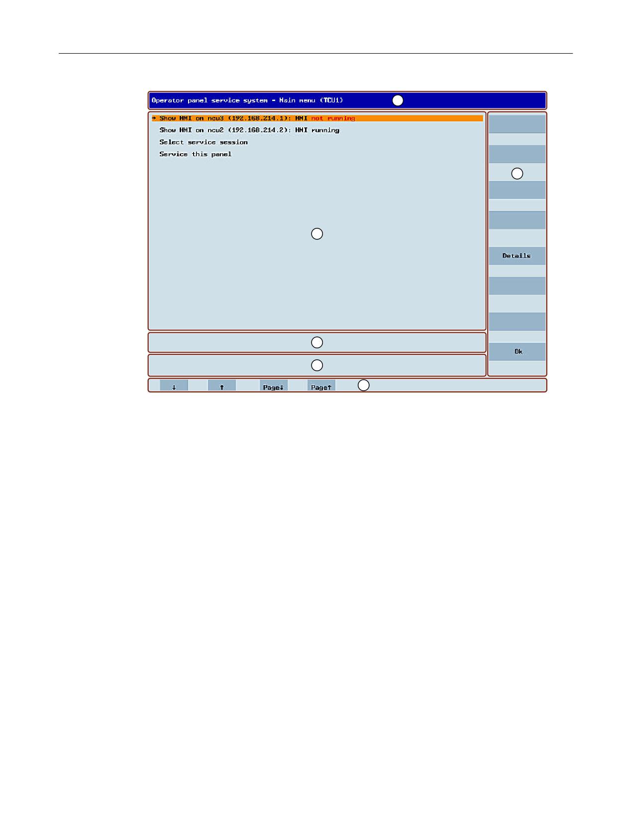
The "Main menu (TCU1)" dialog is started with the menu back key and the <MENU SELECT>
key:
TCU 30.3
54
Manual, 05/2019, A5E40874197B AB
Networking
5.4 Service and diagnostics
① "Main menu" title followed by the TCU name in brackets
② Central area with the list of servers and two further permanent items, "Select service session"
and "Service this panel":
● "Select service session" triggers a server scan which detects all the VNC servers in the local
system network. These are then displayed in a session menu which largely reflects the main
menu.
● "Service this panel" opens the "Service menu for operator panel" submenu.
③ Eight vertical softkeys for use depending on the context
④ Four horizontal softkeys for navigating with the cursor
⑤ Message line whose content can be set via HWS commands from the servers
⑥ Error line in which error messages as well as transient status messages are output
Figure 5-2
TCU menu: Main menu
TCU 30.3
Manual, 05/2019, A5E40874197B AB
55
Networking
5.4 Service and diagnostics
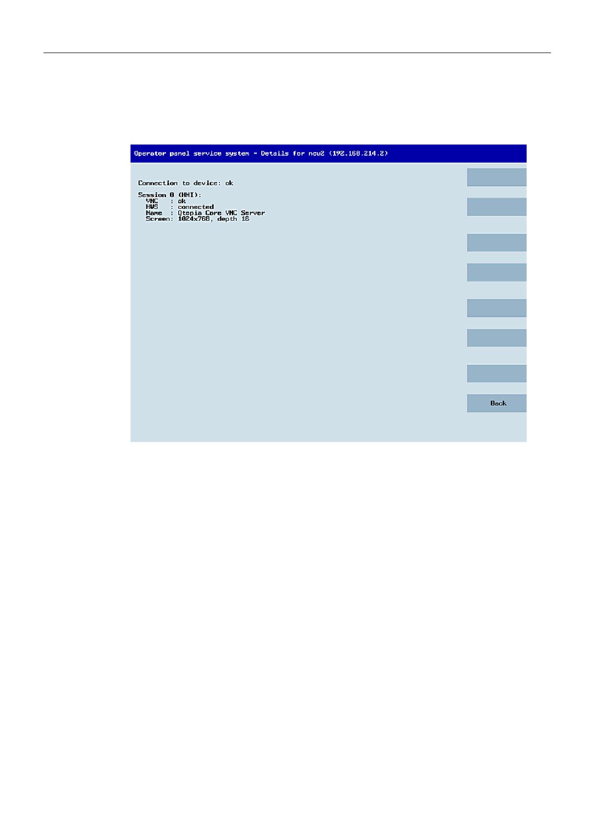
"Details" softkey
The following connection data for the selected device appears when the "Details" softkey is
pressed:
Figure 5-3
TCU menu: Connection data
TCU 30.3
56
Manual, 05/2019, A5E40874197B AB
Networking
5.4 Service and diagnostics
5.4.2
Operating the TCU menu "Service sessions"
"Service sessions" dialog
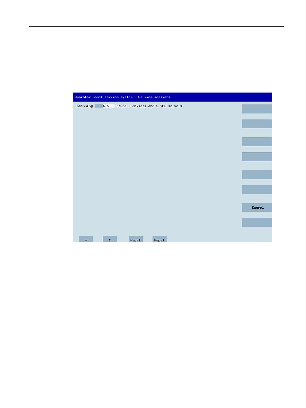
When "Select service session" is selected from the main menu, the resulting process begins by
triggering a server scan:
Figure 5-4
TCU menu: Scanning
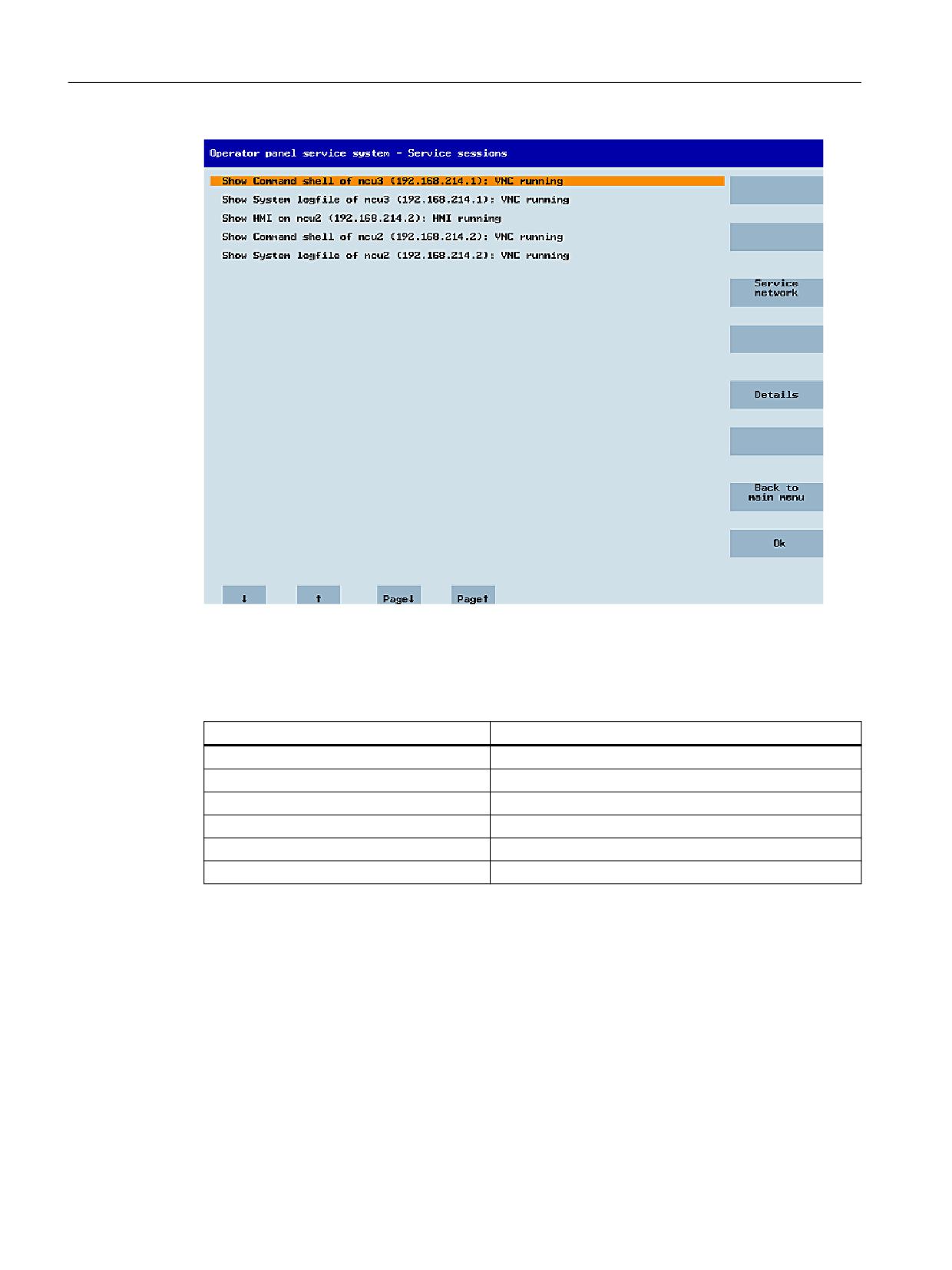
After this, the following dialog appears:
TCU 30.3
Manual, 05/2019, A5E40874197B AB
57
Networking
5.4 Service and diagnostics
Figure 5-5
TCU menu: Active sessions
Central area with the server list:
The individual server lines contain either "Show WHAT on NAME (IP)" or the IP address only
where the name is unknown.
Session number
VNC server
Session 0
HMI
Session 4
Command shell
Session 5
System logfile
Session 6
System Network Center (SNC)
Session <N>
Other servers
These details are followed by a status message regarding the accessibility of the VNC server.
● "Connection not ok" appears if it is already impossible to access the server from the IP side
(if switched off, for example).
● "HMI running/ not running", if an HMI VNC server is accessible.
The VSK8, Return or right cursor keys can be used to launch a VNC viewer for the selected
server.
Connection status:
Further details on the connection status can be called with the "Details" softkey. In the next
dialog, "not ok" or "not running" are accompanied by an additional error message with more
TCU 30.3
58
Manual, 05/2019, A5E40874197B AB
Networking
5.4 Service and diagnostics
precise details on the reason for the loss of function. With more favorable scenarios, the
session name for the VNC server will also be specified along with its resolution.
The connection and HMI status are monitored on a regular basis in the backg16round. This may
mean that these specifications change spontaneously if a change is made on the relevant
server, e.g. it may be switched off, the HMI may become available, etc.
5.4.3
Operating the TCU menu "Service menu"
"Service menu for operator panel (TCU)" dialog
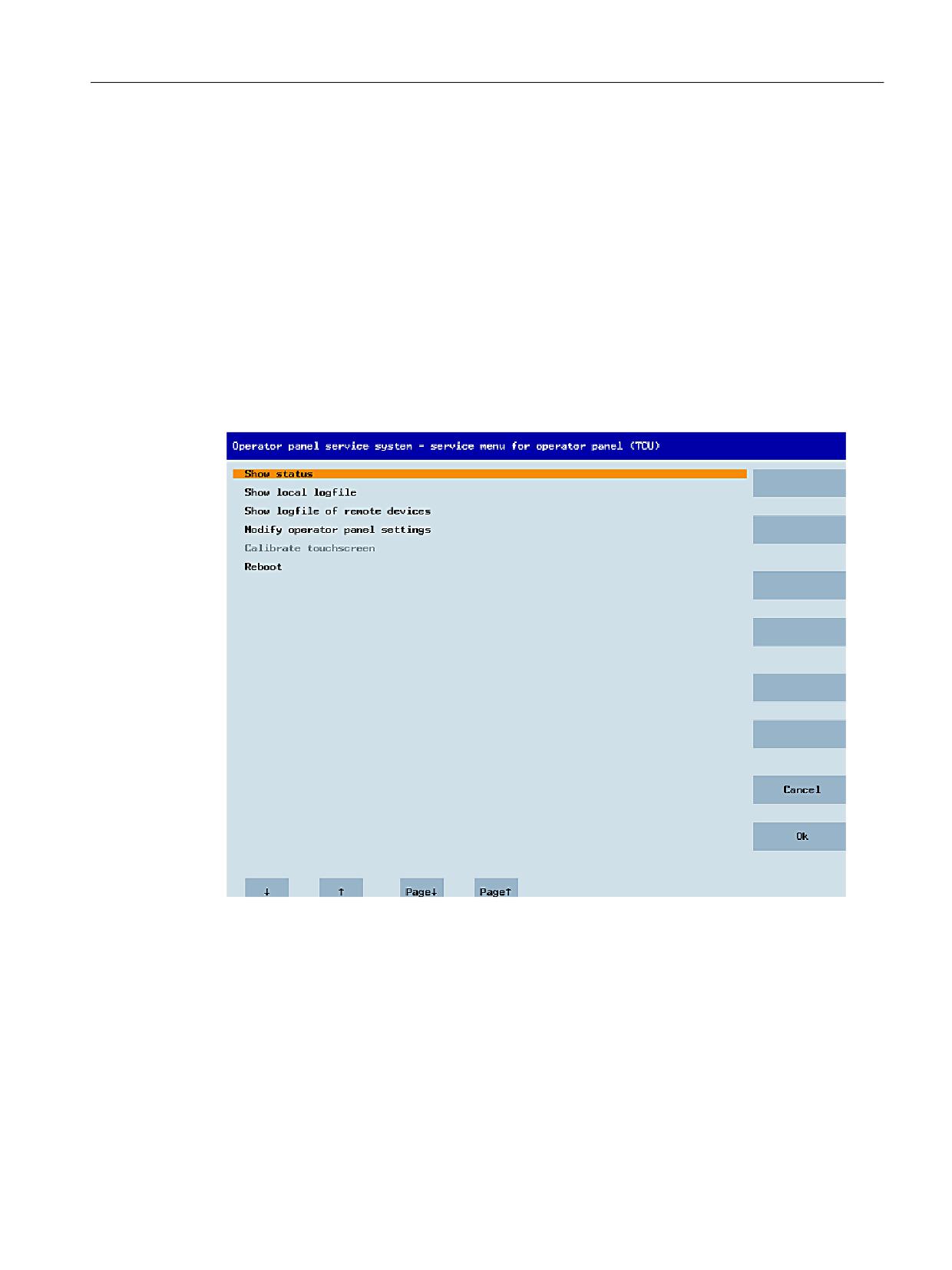
The following dialog appears when "Service this panel" is selected from the main menu:
Figure 5-6
TCU menu: Service menu
TCU 30.3
Manual, 05/2019, A5E40874197B AB
59
Networking
5.4 Service and diagnostics
The following menu items are available here:
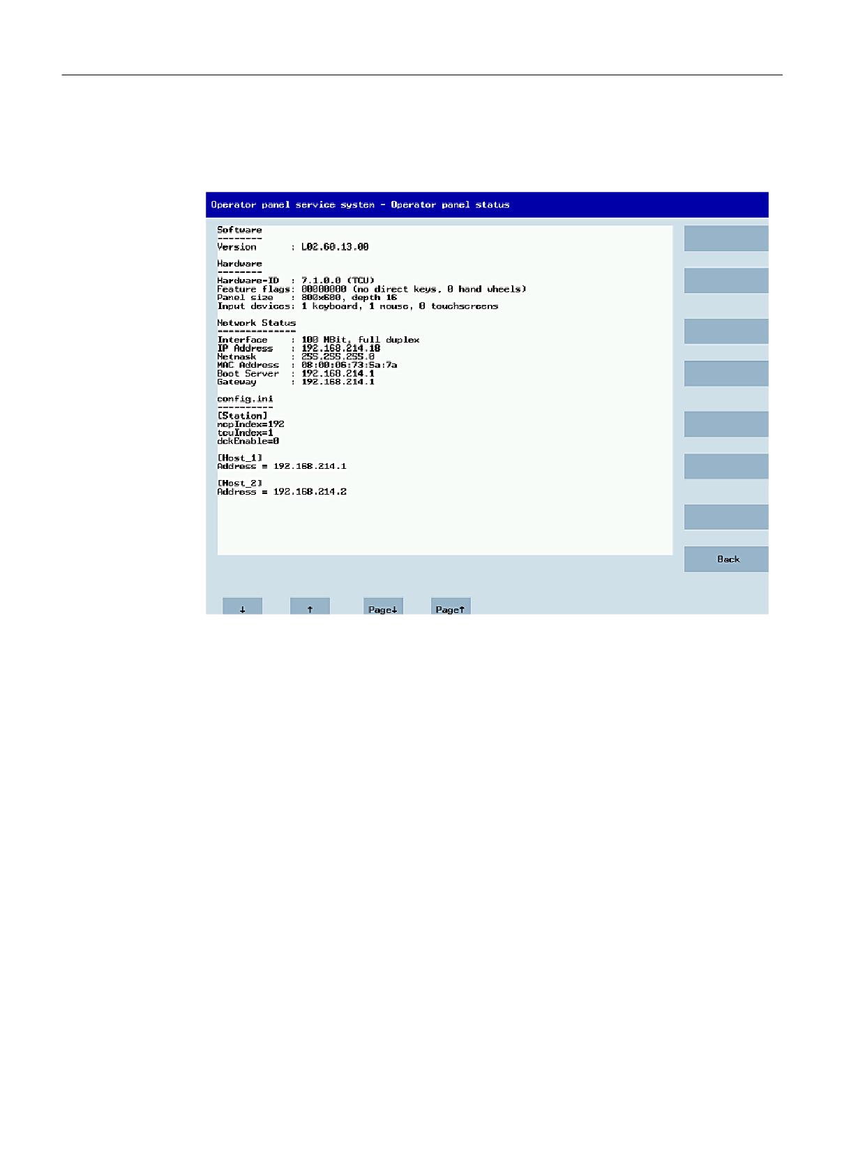
● "Show status" shows status information, for example: Software version, hardware
information, TCU network data, and their configuration:
Figure 5-7
TCU menu: OP status
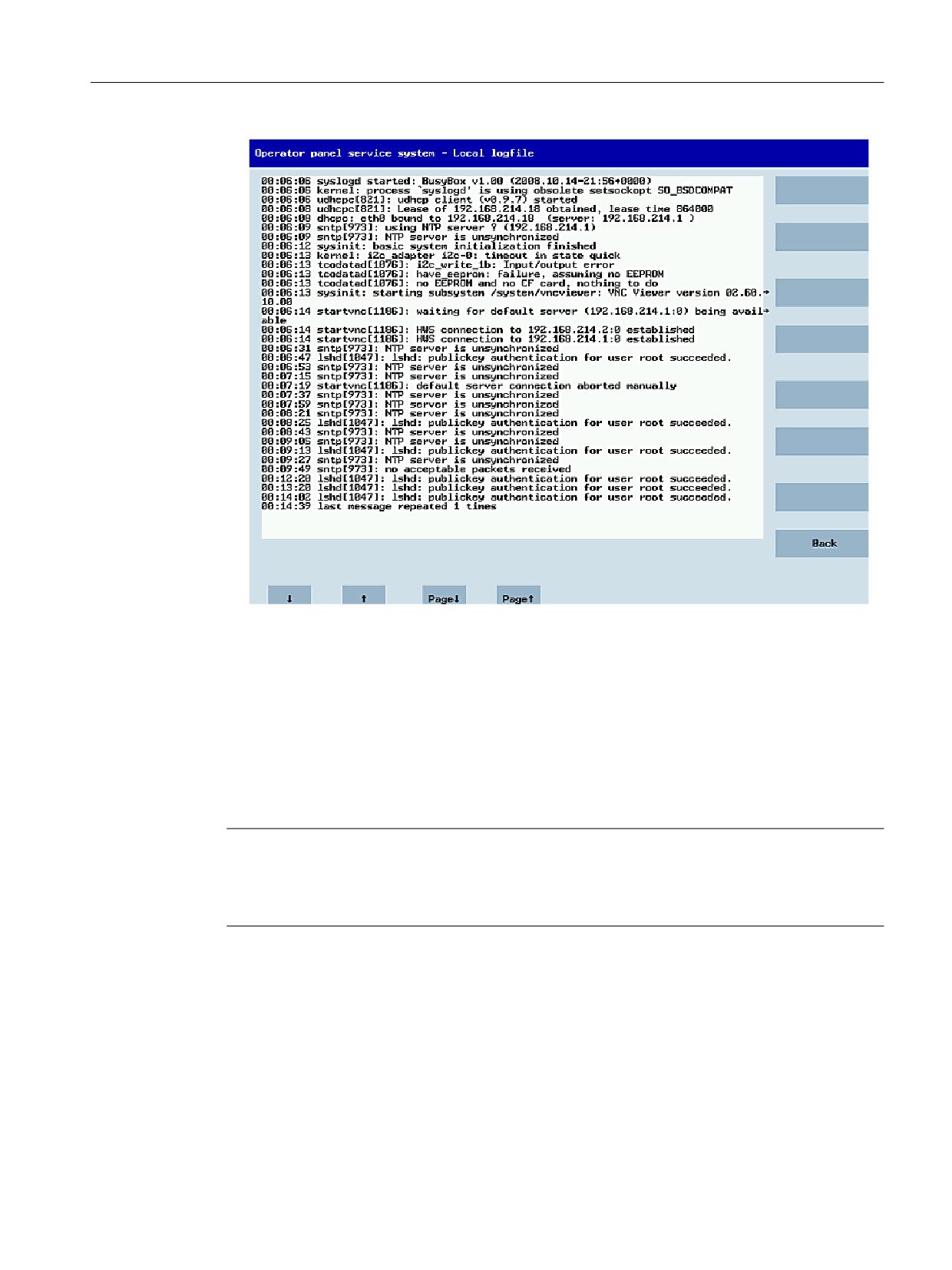
● "Show local logfile" shows a filtered version of the system log file in the /var/log/
messages directory, which contains only the messages of the local TCUs.
Syslog messages received via the network are not displayed.
TCU 30.3
60
Manual, 05/2019, A5E40874197B AB
Networking
5.4 Service and diagnostics
Figure 5-8
TCU menu: Local log file
● "Show logfile of remote devices" shows the log file of the other devices in the network:
The syslog messages of devices in the system network which send syslog messages by
broadcast, such as NCU 7x0, ...
● "Modify operator panel settings" opens another submenu, see next section.
● Calibrate touch screen" is only active if there is a touch screen. This menu item recalibrates
an available touch screen.
● "Reboot" initiates a restart of the TCU.
Note
Long lines are broken and wrapped around.
Lines that are longer than the space available wrap round onto the next line so that you do not
have to scroll horizontally. When this occurs, the line has a right-facing arrow at its right edge.
TCU 30.3
Manual, 05/2019, A5E40874197B AB
61
Networking
5.4 Service and diagnostics
5.4.4
Operating the TCU menu "Modify settings"
"Modify settings for operator panel (TCU)" dialog
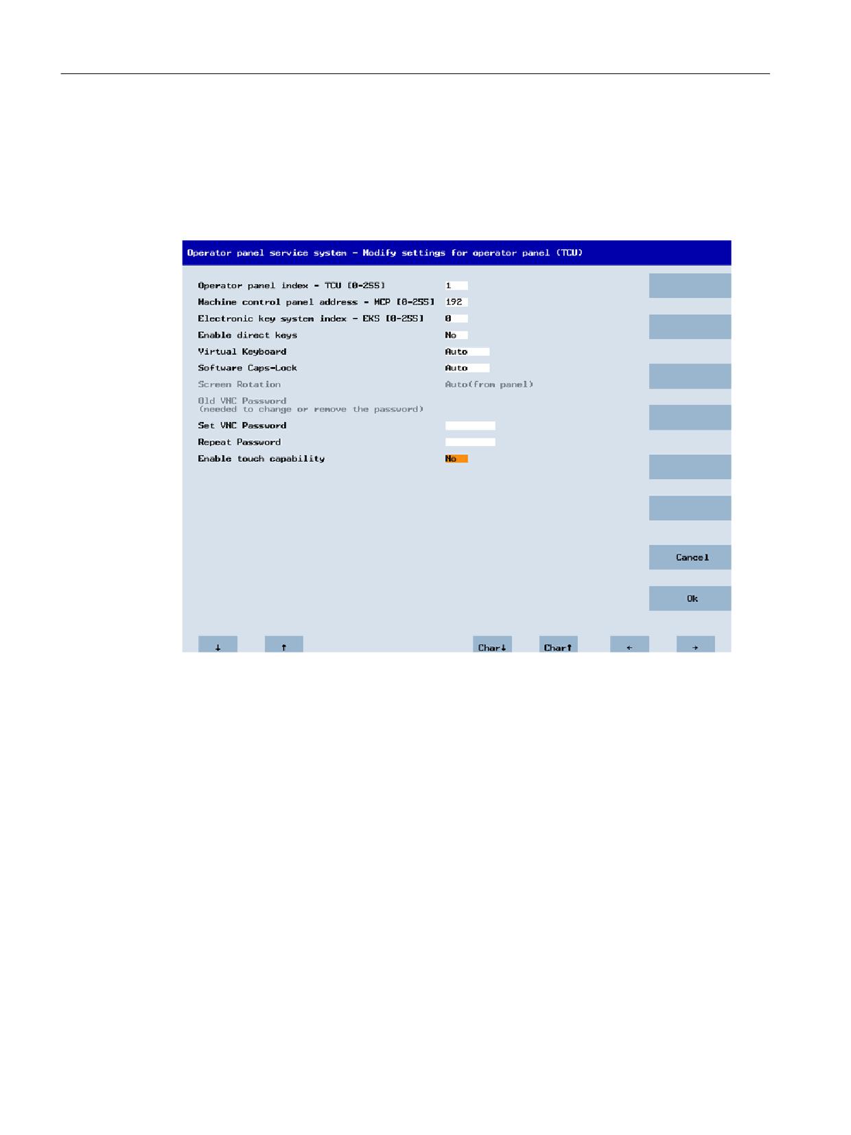
The following dialog appears when "Modify settings" is selected from the main menu:
Figure 5-9
TCU menu: Settings
The following TCU parameters are set here during the first commissioning:
● "HT 8 individual mode" (yes/no)
This is only visible with HT 8, and is used to switch between Auto Mode and Individual Mode.
You do not have to make settings for an HT 8 in Auto Mode because the name is generated
automatically: ("DIP<n>") MCP address and TCU index are derived from the DIP setting
("DIP<n>").
● "Operator panel index - TCU" (0-255)
Defines the TCU index; see column "TCU" on the user interface.
● "Machine control panel address - MCP" (0-255)
Specifies the address of the associated MCP; see column "MCP" on the user interface.
● "Electronic key system index - EKS" (0-255)
Specifies the index of the associated EKS; see column "EKS" on the user interface.
● "Enable direct keys" (yes/no)
Specifies whether direct keys are registered with the PLC (yes) or are treated as ordinary
keys (no); see column "DCK" on the user interface.
TCU 30.3
62
Manual, 05/2019, A5E40874197B AB
Networking
5.4 Service and diagnostics
●
"Virtual Keyboard" (Auto/On/Off)
Specifies whether a virtual keyboard is shown on the screen for touch screens.
Depending on the panel features (Auto), the HMI decides whether a touch screen or
keyboard is available.
This parameter can also be set manually (On/Off).
●
"Software Caps-Lock" (Auto/On/Off)
The HMI can manage the Caps-Lock status of a keyboard in the software itself, when, for
example, the key is not available. This is normally (Auto) switched on via a display machine
data item. This machine data item can be overwritten individually for the TCU with the
setting (On/Off).
●
"Emulation Type" (TCU/TCU20.2/TCU30.3, only for modular TCU30.3)
Specifies which TCU type is to be emulated when the TCU30.3 is operated as replacement
device for an older TCU or as new device on a software version older than 4.7 SP2.
●
"Screen Rotation" (0°/90°/180°/-90°/Auto)
Specifies in which angle the screen is to be rotated in the software. This is useful when the
panel is to be rotated during installation.
For the "Auto" setting, the rotation of the display is taken from the panel.
●
"Old VNC Password"
If a password has already been set, it must be entered here so that it can be changed. If no
password has been set, this field is grayed-out. The existing password can also be deleted
if, after entering the old password, no new password is to be entered at "Set VNC Password"
and "Repeat Password".
●
"Set VNC Password"
Assign a password which is stored in the TCU and, if required, sent to the server when the
VNC connection is established.
●
"Repeat Password"
Repeat the password entered at "Set VNC Password".
●
"Enable touch capability" (yes/no)
Specifies whether the screen can be operated by touch. If you deactivate this option, you will
need a keyboard to reactivate it.
The values are applied and stored with "OK". You can also make any subsequent adaptations
or changes via the user interface in the "Setup" operating area > menu forward key > "OPs"
softkey.
5.4.5
Operating the menu for a new TCU or spare part TCU
Registering a new TCU
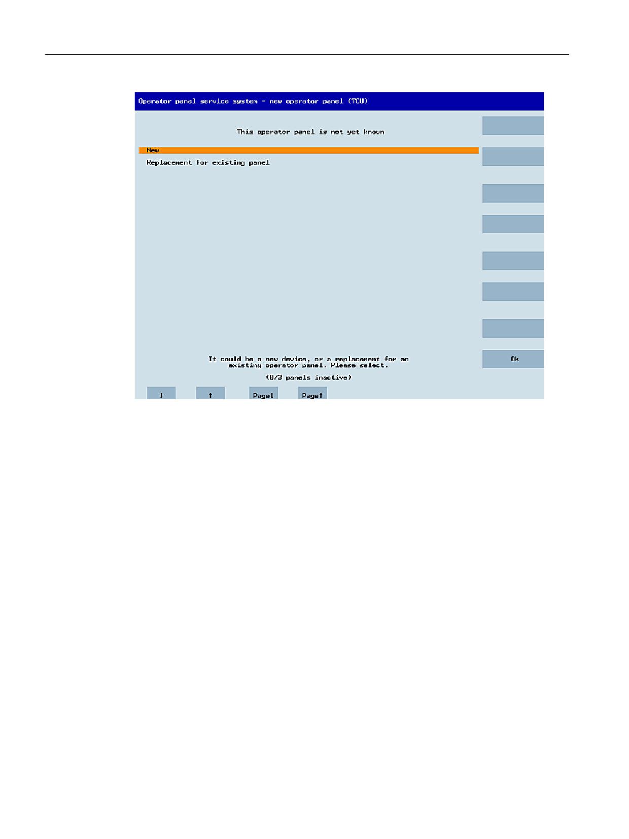
When an unknown TCU, i.e. not yet registered with the boot server, is started, a selection menu
containing both the "New" and "Replacement for existing panel" items is displayed. The
accessibility of all the registered TCUs is tested in the backg16round.
The status of this test is displayed in the message line: "(0/3 panels inactive)".
TCU 30.3
Manual, 05/2019, A5E40874197B AB
63
Networking
5.4 Service and diagnostics
Figure 5-10
TCU menu: New TCU
If all TCUs are active, the new TCU cannot be a spare part. The system will then automatically
switch to the name assignment phase after a set period of time has elapsed.
TCU 30.3
64
Manual, 05/2019, A5E40874197B AB
Networking
5.4 Service and diagnostics
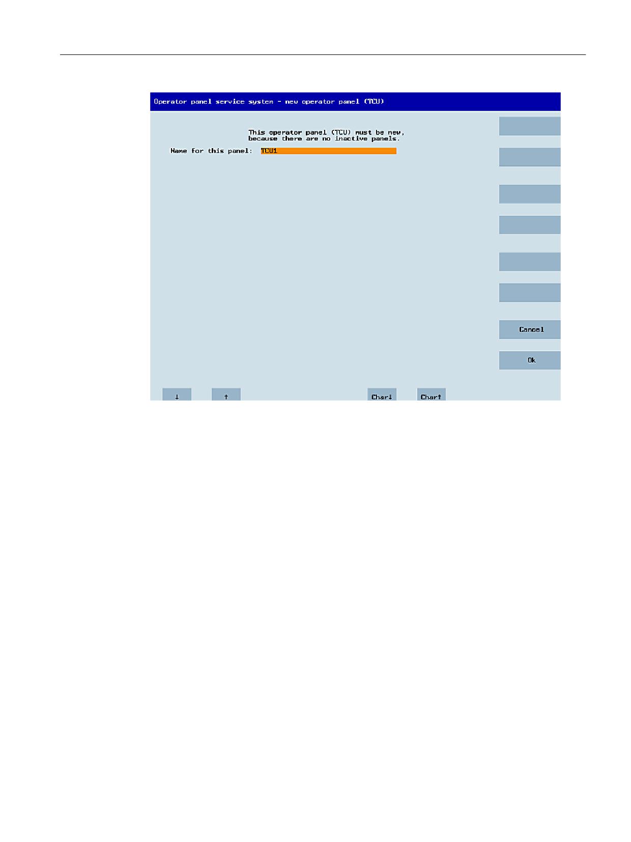
Figure 5-11
TCU menu: Name of TCU
If a TCU30.3 is to be operated with a software version < 4.7 SP2, the TCU is operated in
compatibility mode. If required, you can view and change the emulation type in the settings.
Replacing a device
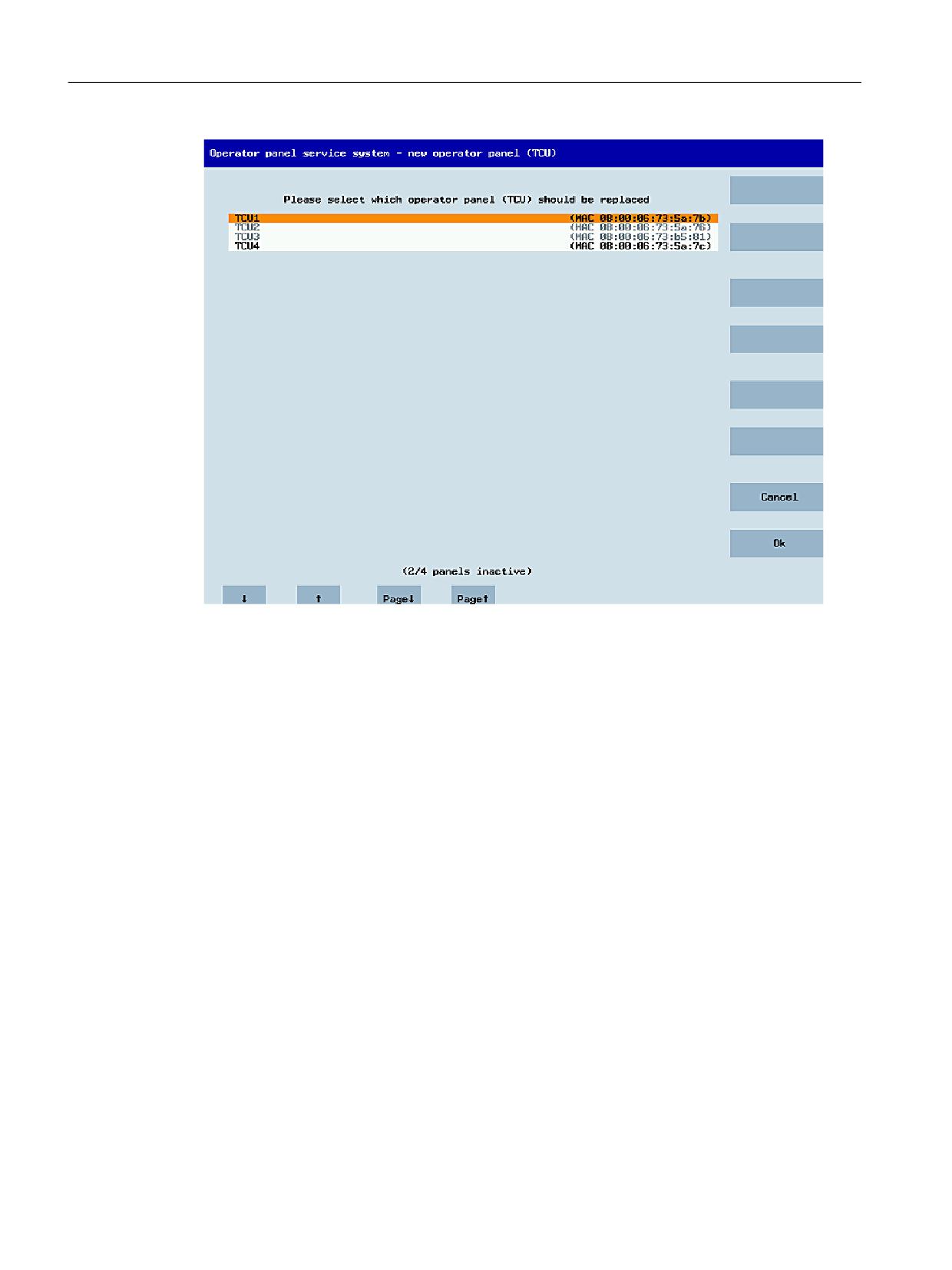
If "Replacement" is selected, all the registered TCUs will appear in a selection menu. Those
which are active in the network are grayed out. They are functioning and should not be replaced
by a spare part. The cursor automatically defaults to the first line for selection.
As the accessibility test is still running in the backg16round, the active status of the lines may
change if panels are switched on or off.
If a name is ultimately chosen, it will be applied to the new TCU along with the associated saved
settings.
TCU 30.3
Manual, 05/2019, A5E40874197B AB
65
Networking
5.4 Service and diagnostics
Figure 5-12
TCU menu: Replacement TCU
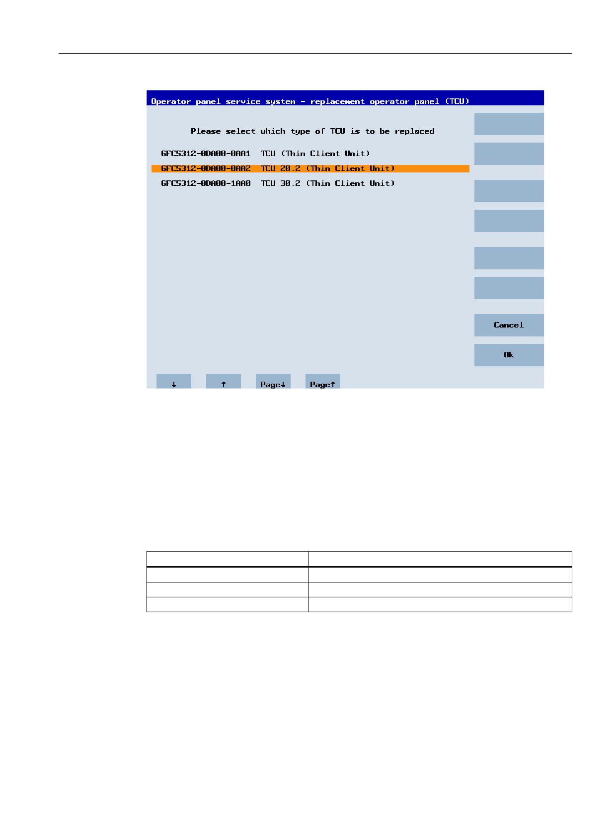
With the TCU30.3, after selecting the TCU to be replaced, a further dialog to select the
emulation type can be displayed in compatibility mode:
TCU 30.3
66
Manual, 05/2019, A5E40874197B AB
Networking
5.4 Service and diagnostics
If a static.ini of the TCU to be replaced (as of SW4.5) is found on the server, then the type of the
old TCU is preselected based on the HW ID found there. If this is not the case, the TCU20.2 type
is selected.
The following TCU types can be emulated:
● TCU
● TCU 20.2
● TCU 30.2
Note that if an older TCU is to be replaced by a TCU30.3, some interfaces cannot be used when
the HMI version is older than V4.7. The following interfaces are affected:
TCU to be replaced
Interfaces that cannot be used
TCU
X212, X213 (because they do not exist in the TCU)
TCU 20.2
X212 (because it does not exist in the TCU 20.2)
TCU 30.2
X211 (because it does not exist in the TCU 30.3)
TCU 30.3
Manual, 05/2019, A5E40874197B AB
67
Networking
5.4 Service and diagnostics
Assigning a name
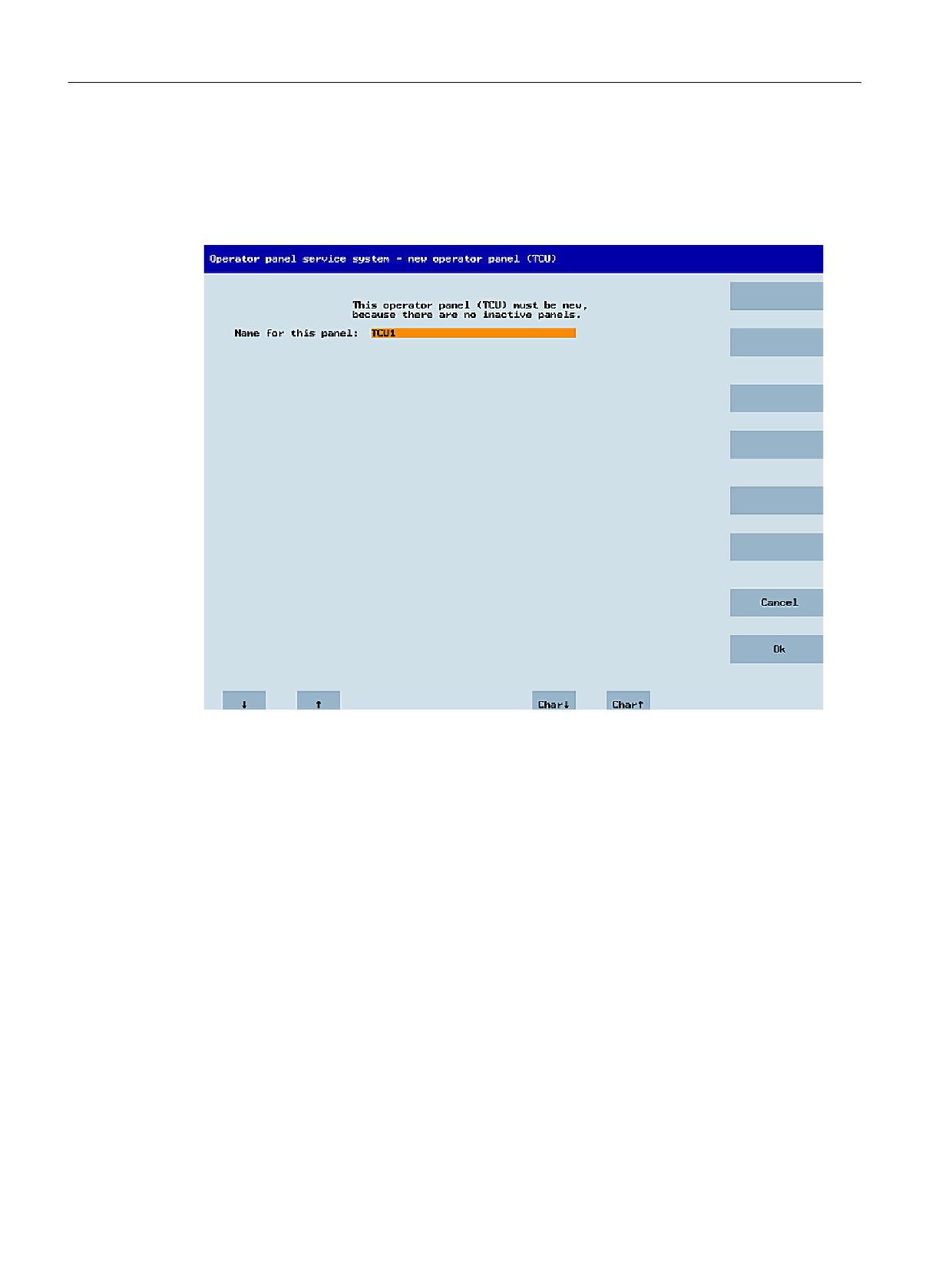
If, as described above, the system automatically follows the "New" path, an additional message
will appear: "This operator panel (TCU) must be new, because there are no inactive panels."
This message will not appear if "New" is selected manually.
Figure 5-13
TCU menu: Name of TCU
An available TCU name is suggested in the input field, although the user is able to change this.
The default name is "TCU<N>", where <N> is the lowest number yet to be used. If, however,
the name is already allocated after the OK softkey has been pressed, which may happen if a
number of TCUs log on at the same time, and the suggestion has not changed, a new and
unused name will be specified.
If the name selected was still available, this will now be allocated, and the TCU settings can still
be adapted if required. To enable any changes to be made, a new dialog appears in which all
the parameters have been pre-assigned their default values. You can make any changes you
like or just select "OK" to accept the existing values.
5.4.6
How to register a TCU on the system network
Requirement
The boot server (NCU or PCU 50/IPC) defined in the system network as a DHCP master must
be switched on and available in the network.
TCU 30.3
68
Manual, 05/2019, A5E40874197B AB
Networking
5.4 Service and diagnostics
Using the TCU
Procedure:
1. Connect the TCU.
This opens the "New operator panel (TCU)" dialog.
2. Select "New" to connect a new TCU and "OK" to confirm.
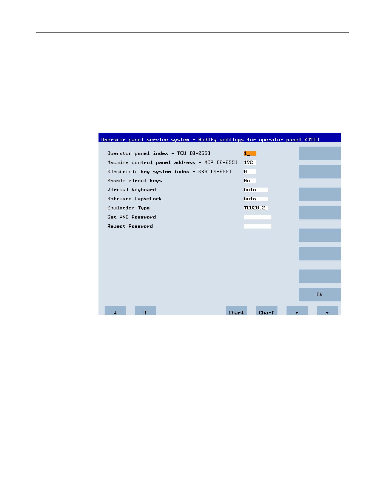
3. In the next dialog, accept the name suggested by the system or enter a name and confirm
this with "OK".
The following parameters are preselected for the TCU:
4. Restart the TCU to apply the new settings.
5. If you want to change the parameters, select "Main menu" > "Service this panel" > "Modify
operator panel settings".
TCU 30.3
Manual, 05/2019, A5E40874197B AB
69
Networking
5.4 Service and diagnostics
Procedure for the HT 8
1. Connect the HT 8 to a connection module and calibrate the touch screen.
Additional softkeys are available for convenient touch panel operation:
- "OK" has the same function as the <INPUT> key
- Select "DEF" to save the "Default" settings.
- "Edit" has the same effect as the <F10> or <MENU SELECT> key.
2. Select HT 8 Individual Mode:
According to the default setting for an HT 8, "HT 8 Individual Mode" is deselected with "No".
This means "Auto" mode is activated for automatic detection in the system network. The HT
8 is automatically detected based on its name "DIP_". If "HT 8 Individual Mode" is activated
with "Yes", the HT 8 is identified by its MAC address on the system network.
3. For an HT 8, confirm the "DIP..." name proposed by the system or adapt the name. You can
select any other characters.
Press the <INPUT> key to apply the following values as default settings for the HT 8:
HT8 Individual Mode
No
Operator panel index - TCU [0-255]
10
Machine control panel address - MCP [0-255]
10
Electronic key system index - EKS [0-255]
0
Enable direct keys
No
The following message will then appear: "New TCU 'DIP10' registered."
Note
TCU index for the HT 8
The TCU index is used to evaluate the direct keys. Direct keys can only be activated by
appropriate devices. For an HT 8 the TCU index cannot be set, but is assigned by the
system.
Activate direct keys
The signals from pressing the direct keys are sent directly to the PLC. In the PLC, the keys
appear as 16 digital inputs.
Additional information on programming the PLC is provided in:
SINUMERIK Basic Functions Function Manual, Basic PLC Program (P3)
Definition: Operator panel
The term operator station designates a unit that consists of an OP/TP, a TCU or PCU/IPC and
a machine control panel (MCP), which are connected to each other via Ethernet.
All TCUs, PCU 50s and IPCs can be used along with the OP/TP with "integrated TCU", e.g.
OP 08T, OP 015T, TP 015AT.
TCU 30.3
70
Manual, 05/2019, A5E40874197B AB
Networking
5.4 Service and diagnostics
Specifying settings without machine control panel
If a PCU, IPC or TCU does not have a machine control panel (MCP), one of the two following
options must be set:
● MCP address = 0 or no entry
After the change of user authorization, there is no switchover of the machine control panel;
the previously active MCP remains active.
● MCP address = 255
If the user authorization is transferred to this PCU, IPC or TCU, the previous machine control
panel is deactivated, and there is no active machine control panel as from this point.
5.4.7
This is how you register a spare part TCU
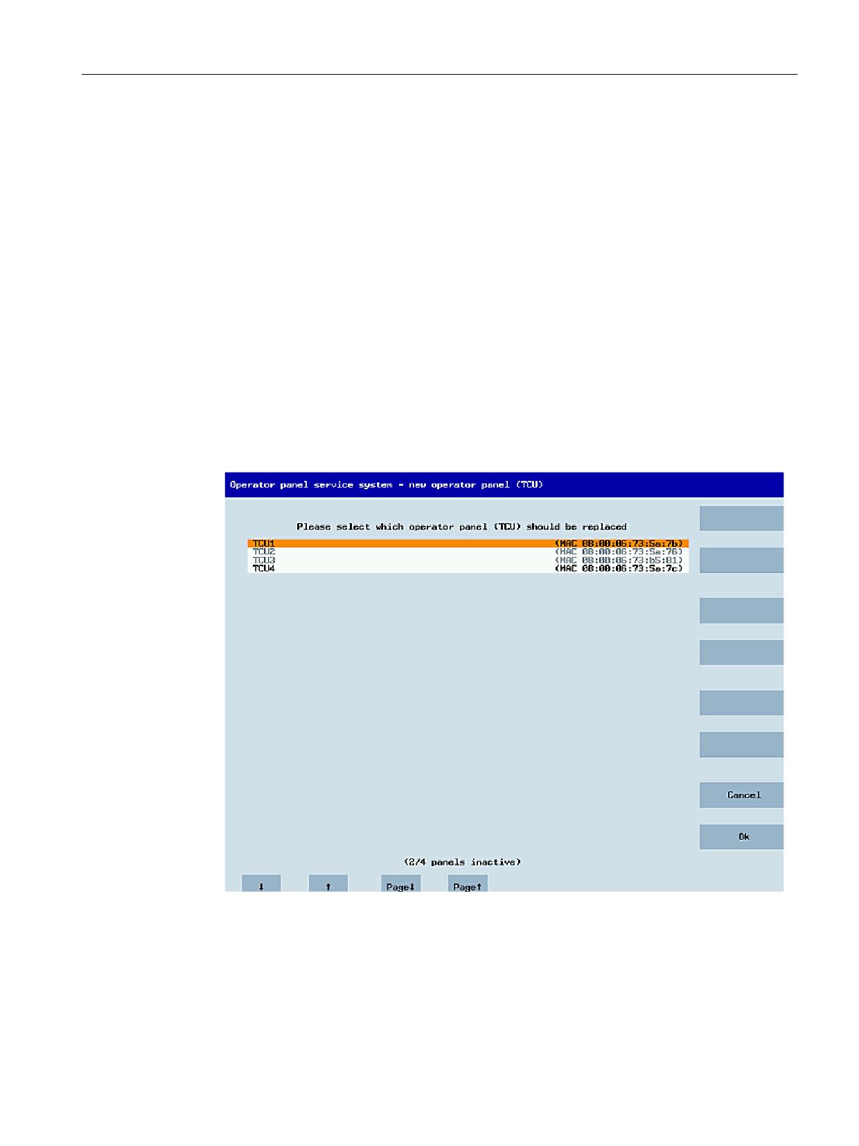
To connect the spare part TCU, proceed as follows:
1. Connect the new TCU.
The "New operator panel (TCU)" dialog opens.
This dialog lists the TCUs on the system network along with their "active" or "inactive" status:
2. Select the name previously assigned to the defective TCU. As a result, the new TCU is
recognized on the network and acquires all of the configuration settings from the TCU that
has been replaced.
TCU 30.3
Manual, 05/2019, A5E40874197B AB
71
Networking
5.4 Service and diagnostics
5.4.8
Booting of the TCU
5.4.8.1
Messages during booting
Messages when booting
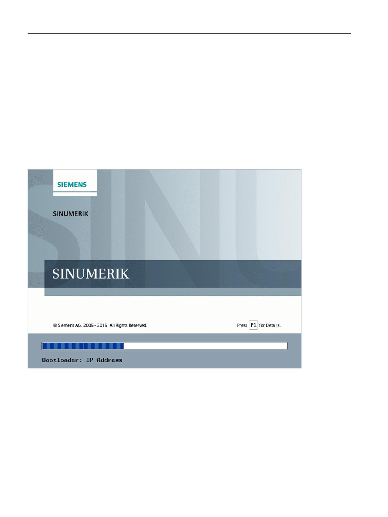
While the TCU boots, a progress indicator is displayed with messages showing the current
status after the BIOS has been loaded and before the operating system is started. While the IP
address is being determined via DHCP and the TFTP is being downloaded (boot image), a
progress bar indicates that booting of the TCU is not yet complete, or that a fault has occurred.
The figure below shows the structure of these messages:
You can see the current boot phase below the progress bar. If a fault occurs, you can call further
information by touching the "F1" field.
TCU 30.3
72
Manual, 05/2019, A5E40874197B AB
Networking
5.4 Service and diagnostics
5.4.8.2
Diagnostics options during booting
Diagnostics while booting supplementary conditions
In the following supplementary conditions, the diagnostics window is displayed and booting of
the TCU is interrupted:
● When the <1 / F1> function is selected during booting
● When a warning message is displayed
● When a fault occurs
You can select functions <1 / F1> to <8 / F8> mentioned below by tapping on the Panel.
Alternatively, you can do this via the corresponding function keys of a connected USB
keyboard.
Using the <1 / F1> function
7hin Client Bootloader
V05.00.45.00
Boot Progress
BIOS Version
V15.00.00.00
MAC Address
08:06:00:F1:F7:F8
Hardware-ID
7.9.2.0
Network link
1000MB, full duplex
Boot from USB
no device found
IP Address
192.168.214.14
Netmask
255.255.255.0
DHCP Server
192.168.214.1
Boot Server
192.168.214.1
Image Metadata
71 bytes
Image Version
V05.00.46.00
Linux Image (linux.bin)
3295436 bytes
Image Kind
from boot server
Booting
ready
<1/F1> protocol <2/F2> Readme_OSS
<7/F7> continue <8/F8> reboot
Key / text
Meaning
F1 protocol
Display detailed information
F2 Readme_OSS
Details of the Open Source licenses
F7 continue
Continue booting of the TCU
F8 reboot
Restart the TCU
TCU 30.3
Manual, 05/2019, A5E40874197B AB
73

Networking
5.4 Service and diagnostics
Press <1 / F1> to continue
If you select function <F1> in the diagnostics window, the, detailed diagnostic information is
output.
Key / text
Meaning
F1 ... F6
Navigate within the window
(alternatively, the relevant keys on the OP can be used).
F7 -detail
Display less information
F8 +detail
Display more information
F9 back
Return to diagnostics window
TCU 30.3
74
Manual, 05/2019, A5E40874197B AB
Service and maintenance
6
Cleaning the device
The TCU is designed for low-maintenance operation.
Preparation
Note
Clean the TCU only when it is switched off.
For cleaning, use a soft cloth moistened either with water or a mild cleaning agent. Use only
dish soap as cleaning agent.
Procedure
Do not spray the cleaning agent directly on the TCU, but rather on a cleaning cloth. Never use
caustic solvents or abrasive cleaners.
Note
Do not clean the TCU using compressed air or steam jets because they can damage it.
Checking the device
In order to prevent foreign bodies or liquids entering the TCU, regularly check the device:
● Ensure that all the housing screws are in place and tight
● For damage to the housing
● For damage to the cable cover or cable entry
Protect the device from environmental effects
Protect the TCU against:
● Direct sunshine and heat sources
● Mechanical vibration and shock
● Dust
● Humidity
● Strong magnetic fields
Suspected malfunction
If you suspect a malfunction due to unusual feedback messages, immediately isolate the
device from power and inform qualified personnel to check for proper functioning.
TCU 30.3
Manual, 05/2019, A5E40874197B AB
75
Service and maintenance
Signs for a suspected malfunction:
● Unusual or no functioning
● Unusual heat generation
● Smoke development
Repair
Send the TCU back to the manufacturer for repair. The TCU may be repaired only there.
TCU 30.3
76
Manual, 05/2019, A5E40874197B AB
Technical data
7
7.1
Technical data
Safety
Safety class
I
Degree of protection accord-
IP00 (open equipment) 2)
ing to EN 60529 1)
IP20 (mounted, end application minimum requirement)
Approvals
CE / cULus
Flame resistance
UL 94 V-1 3)
Electrical data
Overvoltage category
Secondary circuit supplied from primary circuits up to Cat. II,
300 VAC 4)
Power supply 5)
24 VDC (20.4 V ... 28.8 V)
Current consumption
Typically approx. 0.2 A 6)
Maximum approx. 2.9 A
Power consumption, max.
10.5 W 7) / 60 W 8)
Mechanical data (without packaging)
Dimensions
Width: 260 mm
Height: 265 mm
Depth: 34 mm
Weight
1.6 kg
Tightening torques, max.
M3:
0.8 Nm standard
M4:
1.7 Nm
M5:
3 Nm standard
Mechan. stability
According to UL 61010 3)
1) The system installer ensures the system is sealed properly according to IP20, IP classification has not
been checked by UL, UL TYPE 1.
2) Open equipment according to UL 61010.
3) The customer must ensure that the product, with the rear cover to be attached by the customer, meets
the requirements for flame resistance of the material according to UL 94 V-1 and the mechan. stability /
fire protection requirements / touch protection according to UL 61010.
4) If power supply units with primary-side supplies up to 600 VAC (line-to-neutral voltage) have to be
deployed, the transient voltages on the primary side of the power supply unit must be limited to 4000 V.
5) Connect the device only to a 24 VDC power supply that is compliant with protective extra-low voltage
(PELV) requirements according to UL 61010.
6) Without connection of a panel.
7) Only TCU.
8) TCU with OP 019 and 2 x 0.5 A / 4 x 0.1 A on USB.
Note
The 24 VDC power source must be adapted to the input data of the device (see "Electrical
data").
TCU 30.3
Manual, 05/2019, A5E40874197B AB
77

Technical data
7.2 Supplementary electrical conditions
7.2
Supplementary electrical conditions
7.2.1
Power supply
Requirements for DC power supplies
WARNING
Electric shock due to connection of an unsuitable power supply
When equipment is connected to an unsuitable power supply and/or insufficiently grounded
(Page 23), exposed components may carry a hazardous voltage that might result in serious
injury or death.
● Only use power supplies that provide SELV (Safety Extra Low Voltage) or PELV
(Protective Extra Low Voltage) output voltages acc. to UL 61010 for all connections and
terminals of the electronics modules.
WARNING
Inadequately fused supply cables can be life-threatening
In the case of supply lines >30 m, protectors must be installed at the device input to protect
against lightning (surge).
The DC power supply must be connected to the ground/shield of the NC for EMC and/or
functional reasons. For EMC reasons, this connection should only be made at one point. As
a rule, the connection is provided as standard in the S7-300 I/Os. In exceptional
circumstances when this is not the case, the ground connection should be made on the
grounding rail of the NC cabinet (also refer to /EMC/EMC Installation Guide.)
Table 7-1
Requirements of the DC power supply
Rated voltage
According to EN 61131-2
24 VDC
Voltage range (mean value)
20.4 VDC to 28.8 VDC
Voltage ripple, peak/peak
5% (unsmoothed 6-pulse recti-
Powering up time when switched
fication)
on
any
Non-periodic overvoltages
≤ 35 V
Period of overvoltage
≤ 500 ms
Recover time
≥ 50 s
Events per hour
≤ 10
Transient voltage interruptions
Downtime
≤ 3 ms
Recovery time
≥ 10 s
Events per hour
≤ 10
TCU 30.3
78
Manual, 05/2019, A5E40874197B AB
Technical data
7.2 Supplementary electrical conditions
7.2.2
Grounding concept
Components
The SINUMERIK 840D sl system consists of a number of individual components which have
been designed so that the system complies with the appropriate EMC and safety standards.
The individual system components are:
● Numerical Control Unit (NCU)
● Machine Control Panel (MCP), Machine Pushbutton Panel (MPP)
● Keyboard
● Operator panels (operator panel front + TCU/PCU)
● Distributor box and handheld unit
● S7-300 I/O with IM 153 interface module
Grounding measures
The individual modules are attached to a metal cabinet panel. Insulating paints on the mounting
points (e.g. tension jacks) must be removed.
It is permissible to cluster the operator control components regarding connection/potential
bonding.
Example: The control panel on the swivel arm.
It is sufficient in this instance to connect the ground connections of, for example, the PCU, TCU,
and operator panel front using a cable and to route a shared grounding conductor to the central
ground connection in the control cabinet.
Please note that interruption of the grounding during maintenance work is not permissible.
Additional references
EMC Design Guidelines
7.2.3
RI suppression measures
In addition to the protective grounding of system components, special precautions must be
taken to ensure safe, fault-free operation of the system. These measures include shielded
signal lines, special equipotential bonding connections, and isolation and shielding measures.
Shielded signal cables
● Use the specified cables for safe and fault-free operation of the system.
● Connect the shield conductively at both ends to the housing for digital signal transmission.
TCU 30.3
Manual, 05/2019, A5E40874197B AB
79

Technical data
7.2 Supplementary electrical conditions
Cable definition
Definition:
● Signal cables (example)
- Data cables (Ethernet, PROFIBUS, sensor cables, etc.)
- Digital I/Os
- Cables for safety functions (emergency stop, enabling)
● Power cables (example)
- Low-voltage supply lines (230 VAC, +24 VDC, etc.)
- Motor cables
Rules for routing cables
In order to achieve the greatest possible EMC compatibility for the complete system (control,
power unit, machine), the following EMC measures must be carefully observed:
● If necessary, signal and power cables may cross one another (if possible at an angle of 90°),
but must never be laid close or parallel to one another.
● Only use cables approved by SIEMENS for the signal lines from and to the Control Unit.
● Signal cables must not be routed close to strong external magnetic fields (e.g. motors and
transformers).
● If signal lines cannot be routed a sufficient distance away from other cables, they must be
installed in grounded cable ducts (metal).
● The operator panel fronts, MCPs, MPPs, and full keyboards must be installed in metallically
enclosed EMC-compatible housings.
Further information on RFI suppression measures and the connection of shielded cables can
be found in the EMC Installation Guidelines.
7.2.4
SINUMERIK_SouthKorea_Note
EMC limit values in South Korea
The EMC limit values to be complied with for South Korea correspond to the limit values of the
EMC product standard for variable-speed electric drives EN 61800-3, Category C2, or limit
value class A, Group 1 according to EN 55011. By applying suitable supplementary measures,
the limit values according to Category C2 or according to limit value class A, Group 1, are
maintained. Further, additional measures may be required, for instance, using an additional
radio interference suppression filter (EMC filter).
TCU 30.3
80
Manual, 05/2019, A5E40874197B AB

Technical data
7.3 Climatic and mechanical environmental conditions
The measures for EMC-compliant design of the system are described in detail in this manual
respectively in the Installation Guideline EMC.
Please note that the final statement on compliance with the standard is given by the respective
label attached to the individual unit.
7.3
Climatic and mechanical environmental conditions
7.3.1
Transport and storage conditions
The components of the SINUMERIK 840D sl system exceed the requirements according to
EN 61800-2 with regard to shipping and storage conditions.
The following data applies under the following conditions:
● Long-term storage in the transport and product packaging:
At weather-protected locations that have continuous contact with outside air through
openings.
● Transport in the transport packaging:
- In unventilated containers under conditions not protected from weather effects.
- In the "cold" in accordance with outside air.
- Air transport in the air-conditioned cargo hold.
Table 7-2
Ambient conditions during storage and transport
Type of condition
Permissible range/class
Transport
Storage
Classification
EN 60721-3-2
EN 60721-3-1
Climate class
2K4
1K4
Ambient temperature 1)
-40° C ... +70° C
-25° C ... +55° C
Biological environmental condi-
2B1 2)
1B1 2)
tions
Chemically active environmental
2C2 3)
1C2 3)
conditions
Mechanical environmental condi-
Class 2M3 according to EN
Class 1M2 according to EN
tions
60721-3-2, in transport pack-
60721-3-1, in product packag-
aging 4)
ing 5)
Maximum permissible tempera-
Direct interaction in air/air:
30 k/h
ture change
-40°/+30° C at 95% relative
humidity
Relative humidity (without conden-
5 to 95%
sation)
Precipitation, rain
6 mm/min 2)
Not permissible
Water other than rain
1 m/s and wet loading surfa-
Not permis-
1 m/s and wet
ces 6)
sible 7)
loading surfaces 6)
TCU 30.3
Manual, 05/2019, A5E40874197B AB
81

Technical data
7.3 Climatic and mechanical environmental conditions
Type of condition
Permissible range/class
Height
Max. 4,000 m above sea level
Condensation, splash water,
Permissible
Not permis-
Permissible 6)
icing, salt spray
sible 7)
1)
Transport and storage of operator panel fronts and diskette drives: -20° C to +55° C.
2)
Mold growth, slime, rodents, termites and other animal vermin are not permissible.
3)
In marine- and weather-resistant transport packaging (container).
4)
Transport packaging is either packaging that is directly suitable for transport or secondary packaging,
which together with the product packaging, satisfies the requirements for transport.
5)
Product packaging (storage packaging) is an individual packaging for storage and does not satisfy the
requirements for transport. As a consequence, product packaging is therefore not suitable for
shipping.
6)
For storage in the transport packaging.
7)
For storage in the product packaging.
Note
Remove the transport protective foil and packaging material before installing the components.
7.3.2
Operating conditions
The components of the SINUMERIK 840D sl system are intended for a weatherproof, fixed
location. The documented
environmental conditions apply to the climate in the immediate vicinity of the units and to the
entry of the cooling air. They exceed the requirements according to EN 60204-1, EN 61800-2,
EN 61131-2 and IEC 62477-1.
NOTICE
Damage to components by coolants and lubricants
The SINUMERIK operator components have been designed for industrial use, particularly on
machine tools and production machines. This also takes into account the use of commercially
available coolants and lubricants. The use of aggressive compounds and additives can
damage components and result in their failure.
Contact between the operator components and coolants and lubricants should be avoided as
far as possible, as resistance to all coolants and lubricants cannot be guaranteed.
Ambient climatic conditions
Climate class according to EN
Better than class 3K3
60721-3-3
Temperature
0 ... 55° C (without derating)
Installation altitude
Up to 1000 m without derating
From 1000 m to 3000 m with linear ambient temperature de-
rating, -0.5 K per 100 m
TCU 30.3
82
Manual, 05/2019, A5E40874197B AB

Technical data
7.3 Climatic and mechanical environmental conditions
Ambient climatic conditions
Relative humidity
5 ... 95% (no condensation)
Oil mist, salt mist, ice formation, con-
Not permitted
densation, dripping water, spraying
water, splashing water and water jets
Biological, chemical, electrical and mechanical influences, pollutants
Biological environmental conditions
Class 3B1 according to EN 60 721-3-3:
Mold, mold growth, slime, rodents, termites and other animal
vermin are not permissible.
Chemically active environmental con-
Class 3C1 according to EN 60721-3-3
ditions
Mechanically active environmental
Class 3M1 according to EN 60721-3-3:
conditions
Conductive dust not permissible.
Classification of the mechanical
3M3 for components on the machine
environment
3M1/3M2 for components in the control cabinet
Vibration test in operation
According to IEC 60068-2-6 test Fc (sinusoidal)
●
10…57 Hz: 0.075 mm deflection amplitude
●
57…150 Hz: 1 g acceleration amplitude
●
10 frequency cycles per axis
Shock test in operation
According to IEC 60068-2-27 test Ea (half-sine)
●
5 g peak acceleration
●
30 ms duration
●
3 shocks in all three axes in both directions
Degree of contamination
2 (only use indoors)
EMC conducted / radiation
Class C2 according to EN 61800-3
Note
The user must consider radio interference for the complete system. Particular attention should
be paid to cabling. Please contact your sales representative for assistance and support.
Note
In a residential environment, this product can cause high-frequency interference, which may
make interference suppression measures necessary.
Have the installation and commissioning with appropriate radio interference suppression
measures performed by qualified personnel.
TCU 30.3
Manual, 05/2019, A5E40874197B AB
83
Technical data
7.5 Recycling and disposal
7.4
Standards and approvals
Approvals
CE approval
Figure 7-1
CE marking
The operator panels and the safety-relevant accessories satisfy the requirements and
protection objectives of the following EC directives. The operator panels and the safety-
relevant accessories comply with the harmonized European standards (EN), promulgated in
the Official Journals of the European Community:
●
2004/108/EC "Electromagnetic Compatibility" (EMC directive)
● Directive 2006/42/EC of the European Parliament and Council of May 17, 2006, on
machinery, and Directive 95/16/EC (amendment)
7.5
Recycling and disposal
For environmentally friendly recycling and disposal of your old device, please contact a
company certified for the disposal of electrical and electronic waste and dispose of the device
in accordance with the regulations in your country.
TCU 30.3
84
Manual, 05/2019, A5E40874197B AB
Spare parts / accessories
8
8.1
Accessories
Table 8-1
Accessories for the TCU
Component
Description
Quantity
Article number
Mounting bracket
Mounting bracket for PCU, video link re-
1 set
6FC5248-0AF20-2AA0
ceiver or TCU behind operator panel front
(2 items)
Direct key cable
Ribbon cable for connection of the direct
1
6FC5347-0AF10-0AA0
key interfaces for OP and TCU.
Industrial
IE FC Standard Ca-
4-core, shielded TP installation cable for
1
6XV1840-2AH10
Ethernet ca-
ble GP 2 x 2 (Type A)
connection to IE FC Outlet RJ45/
ble
IE FC RJ45 Plug; PROFINET-compatible;
with UL approval;
sold by the meter (max. 1000 m; min. 20 m);
IE FC Trailing Cable
4-core, shielded TP installation cable for
1
6XV1840-3AH10
GP 2 x 2 (Type C)
connection to IE FC Outlet RJ45/
IE FC RJ45 Plug 180/90 for use in trailing
cables; PROFINET-compatible; without UL
approval;
sold by the meter (max. 1000 m; min. 20 m);
Plug con-
IE FC RJ45 Plug 180
RJ plug connector for Industrial Ethernet
1
6GK1901-1BB10-2AA0
nector
with robust metal housing and integrated
cutting/clamping contacts; with 180° outgo-
ing cable
Spare parts for the TCU
There are no parts of this device that can be replaced by the user.
8.2
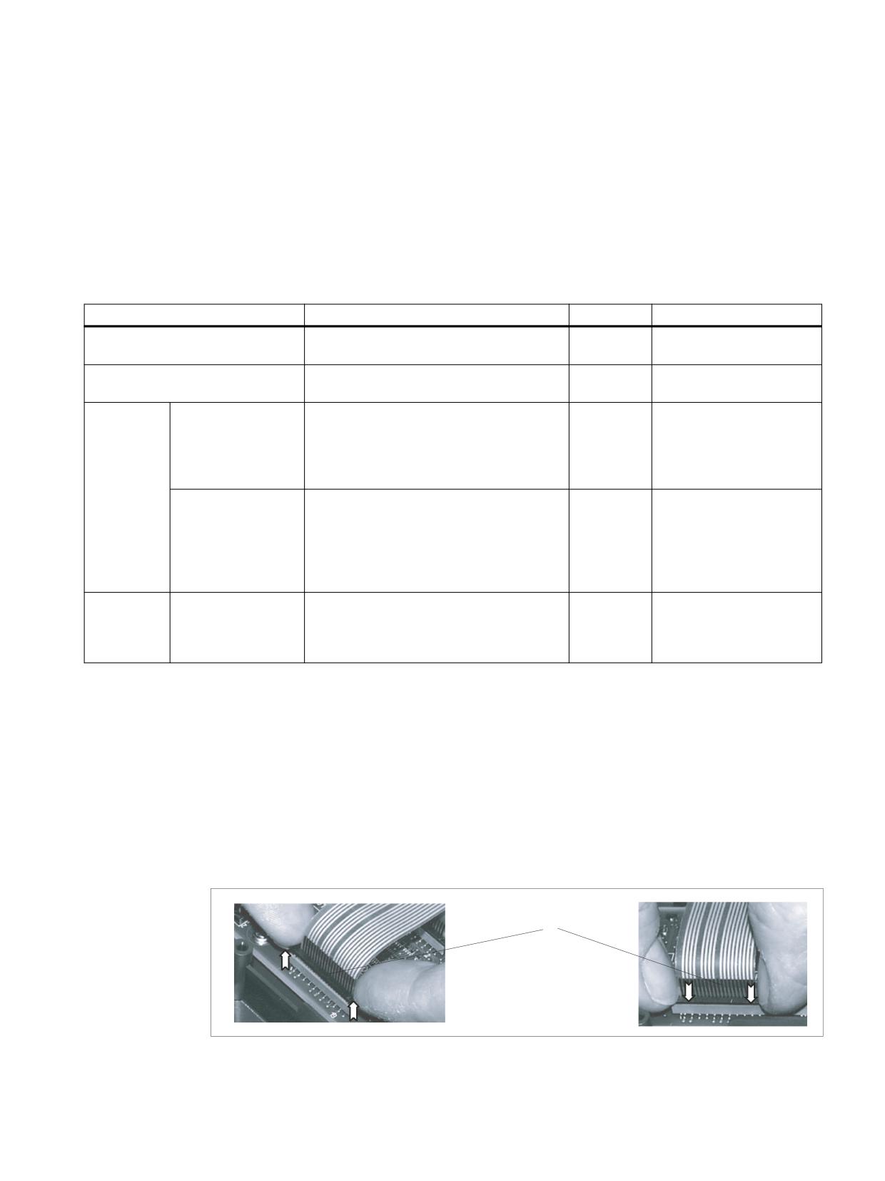
Handling membrane connectors
When replacing parts it can sometimes be necessary to disconnect membrane connectors
from the boards and reconnect them again.
This should be done as follows:
(1)
Clamping frame of socket
TCU 30.3
Manual, 05/2019, A5E40874197B AB
85
Spare parts / accessories
8.2 Handling membrane connectors
Figure 8-1
Removing (left) and attaching (right) a membrane connector
Unplugging the membrane connector
1. Loosen the dark clamping frame of the socket by pushing it up with your fingernails until it
engages in its upper, unlocked position (Fig. left).
2. Carefully pull off the membrane connector upward.
Plugging in the membrane connector
1. With the clamping frame in the upper position, carefully plug the membrane connector into
the socket.
2. Lock it in place by pushing down the clamping frame (Figure right).
TCU 30.3
86
Manual, 05/2019, A5E40874197B AB
e interface for
Preface_______________
4 axes
1
Safety information______
2
System overview_______
SINUMERIK
3
Description__________
SINUMERIK 840D sl / 840Di sl /
4
802D sl
Hardware___________
ADI4 - Analog drive interface for
5
4 axes
Parameter assignment ____
Manual
6
Further information______
Valid for
Control
SINUMERIK 840D sl/840DE sl
SINUMERIK 840Di pl/840DiE pl
SINUMERIK 840Di sl/840DiE sl
SINUMERIK 802D sl
Software Version
ADI4 system software 1.4.8
03/2010
6FC5297-0BA01-0BP5
Preface
Structure of the manual
SINUMERIK® Documentation
The SINUMERIK documentation is organized in 3 parts:
● General documentation
● User documentation
● Manufacturer/Service Documentation
Information on the following topics is available at
● Ordering documentation
Here you can find an up-to-date overview of publications.
● Downloading documentation
Links to more information for downloading files from Service & Support.
● Researching documentation online
Information on DOConCD and direct access to the publications in DOConWEB.
● Compiling individual documentation on the basis of Siemens contents with the
My Documentation Manager (MDM), refer to http://www.siemens.com/mdm.
My Documentation Manager provides you with a range of features for generating your
own machine documentation
● Training and FAQs
Information on the range of training courses and FAQs (frequently asked questions) are
available via the page navigation
Target group
This documentation is intended for manufacturers of machine tools, particularly:
● Project engineers, electricians and installers
● Maintenance and service personnel
Benefits
The information in this manual facilitates installation and connection of the SINUMERIK
840D numerical control in the control cabinet.
ADI4 - Analog drive interface for 4 axes
Manual, 03/2010, 6FC5297-0BA01-0BP5
3

Preface
Standard scope
This documentation only describes the functionality of the standard version. Extensions or
changes made by the machine manufacturer are documented by the machine manufacturer.
Other functions not described in this documentation might be executable in the control.
However, no claim can be made regarding the availability of these functions when the
equipment is first supplied or in the event of servicing.
For the sake of simplicity, this documentation does not contain all detailed information about
all types of the product and cannot cover every conceivable case of installation, operation, or
maintenance.
Technical Support
If you have any technical questions, please contact our hotline:
Europe/Africa
Phone
+49 180 5050 222
Fax
+49 180 5050 223
0.14 €/min. from German landlines, max. 0.42 €/min for calls from a mobile phone
Internet
America
Phone
+1 423 262 2522
Fax
+1 423 262 2200
E-mail
mailto:techsupport.sea@siemens.com
Asia/Pacific
Phone
+86 1064 757575
Fax
+86 1064 747474
E-mail
mailto:support.asia.automation@siemens.com
Note
For technical support telephone numbers for different countries, go to:
Questions about the documentation
If you have any questions (suggestions, corrections) regarding this documentation, please
fax or e-mail us at:
Fax:
+49 9131 98 2176
E-mail: mailto:docu.motioncontrol@siemens.com
A fax form is available in the appendix of this document.
ADI4 - Analog drive interface for 4 axes
4
Manual, 03/2010, 6FC5297-0BA01-0BP5
Preface
SINUMERIK Internet address
EC Declaration of Conformity
The EC Declaration of Conformity for the EMC Directive can be found/obtained:
● On the Internet: http://support.automation.siemens.com
under product/order number 15257461
● From the relevant regional office of the I DT MC division of Siemens AG
Convention
Throughout this document, the term "Control Unit" is also used for product designations
NCU 7x0, provided that the technical conditions described are applicable to all variants.
ADI4 - Analog drive interface for 4 axes
Manual, 03/2010, 6FC5297-0BA01-0BP5
5
Table of contents
Preface
3
1
Safety information
9
1.1
Danger notices
9
1.2
ESD information
10
1.3
Safe isolation to EN 61800-5-1
11
1.4
RI suppression measures
12
2
System overview
15
3
Description
17
3.1
Properties
17
3.2
Essential features
17
3.3
Order number and firmware version
17
3.4
Boundary conditions
18
4
Hardware
19
4.1
Overview of connections
19
4.2
Interface description
20
4.2.1
Interface overview
20
4.2.2
Interface (X1): External power supply
20
4.2.3
Interface (X2): PROFIBUS DP
21
4.2.4
Interface (S2): PROFIBUS address
22
4.2.5
Interface (X3): Analog setpoint interface
22
4.2.6
Interfaces (X4-1/X4-2/X5-1/X5-2): Encoder interfaces
24
4.2.7
Interface (X6-1): Digital outputs
28
4.2.8
Interface (X6-2): Digital inputs
31
4.2.9
Interface (H1/H2): Module status
34
4.3
Control cabinet installation
34
4.4
Power supply
35
4.5
Grounding
37
4.6
Dimension drawing
38
4.7
Technical data
39
5
Parameter assignment
41
5.1
Boundary conditions of ADI4 DP slave
41
5.2
Preconditions, SINUMERIK 802D sl
41
5.3
Preconditions, SINUMERIK 840Di sl
41
5.4
Preconditions, SINUMERIK 840D sl
42
5.5
PROFIBUS DP parameter assignment
43
5.5.1
Parameter assignment sequence
43
ADI4 - Analog drive interface for 4 axes
Manual, 03/2010, 6FC5297-0BA01-0BP5
7
Table of contents
5.5.2
Inserting an ADI4 DP slave in the configuration
44
5.6
PROFIBUS parameters for SINUMERIK 802D sl
44
5.7
PROFIBUS parameters
45
5.7.1
Parameter components
45
5.7.2
PROFIBUS address
45
5.7.3
Message frame type
46
5.7.4
I/O addresses
51
5.7.5
Consistency
51
5.8
Function parameters for SINUMERIK 802D sl
52
5.9
Function parameters
52
5.9.1
Encoder type
53
5.9.2
Unipolar spindle or unipolar motor
55
5.9.3
Shutdown ramp
56
5.9.4
Shutdown delay
56
5.9.5
Tolerable sign-of-life failures
57
5.9.6
Reserved bits for fine resolution
57
5.9.7
611U conformant mode
58
5.9.8
Homing using encoder zero mark
59
5.9.9
Homing using external zero mark
60
5.9.10
Boundary conditions
61
5.10
Parameterization of the DP communication
62
5.10.1
Parameter assignment of the equidistant cyclic DP communication
62
5.10.2
Activation of the equidistant DP cycle
63
5.10.3
Equidistant master cyclic component TDX
64
5.10.4
Equidistant DP cycle TDP
66
5.10.5
DP cycle TDP
67
5.10.6
Master application cycle TMAPC
69
5.10.7
Actual value acquisition Ti
72
5.10.8
Setpoint acceptance To
74
5.10.9
Alignment
75
5.10.10
Boundary conditions
78
6
Further information
81
6.1
Wiring of drive ready signals
81
6.2
Supported SSI encoder formats
81
6.3
Linear encoder with distance-coded zero marks / reference marks
82
Index
87
ADI4 - Analog drive interface for 4 axes
8
Manual, 03/2010, 6FC5297-0BA01-0BP5

Safety information
1
1.1
Danger notices
The following notices are intended firstly for your personal safety and secondly to prevent
damage occurring to the product described or any connected devices and machines. Non-
observance of the warnings can result in severe personal injury or property damage.
DANGER
Only appropriately qualified personnel may commission/start-up SINUMERIK equipment.
The personnel must take into account the information provided in the technical customer
documentation for the product, and be familiar with and observe the specified danger and
warning notices.
When electrical equipment and motors are operated, the electrical circuits automatically
conduct a dangerous voltage.
When the system is operating, dangerous axis movements may occur throughout the entire
work area.
A potential fire hazard exists due to the energy being transferred in the equipment and the
work materials used.
All work on the electrical system must be performed after the system has been switched off
and disconnected from the power supply.
DANGER
Proper transportation, expert storage, installation and mounting, as well as careful
operation and maintenance are essential for this SINUMERIK device to operate correctly
and reliably.
The details in the catalogs and proposals also apply to the design of special equipment
versions.
In addition to the danger and warning information provided in the technical customer
documentation, the applicable national, local, and system-specific regulations and
requirements must be taken into account.
Only protective extra-low voltages (PELVs) that comply with EN 61800-5-1 can be
connected to all connections and terminals between 0 and 48 V.
Should it be necessary to test or take measurements on live equipment, then the
specifications and procedural instructions defined in Accident Prevention Regulation VBG
A2 must be adhered to, in particular § 8 "Permissible deviations when working on live
components". Suitable electric tools should be used.
ADI4 - Analog drive interface for 4 axes
Manual, 03/2010, 6FC5297-0BA01-0BP5
9

Safety information
1.2 ESD information
WARNING
Operating the equipment in the immediate vicinity (< 1.5 m) of mobile telephones with a
transmitting power of > 1 W may lead to incorrect functioning of the devices.
Connecting cables and signal lines should be installed so that inductive and capacitive
interference does not in any way impair the automation and safety functions.
DANGER
Repairs to devices that have been supplied by our company may only be carried out by
SIEMENS customer service or by repair centers authorized by SIEMENS.
When replacing parts or components, only use those parts that are included in the spare
parts list.
EMERGENCY STOP devices EN 60204-1 (VDE 0113 Part 1) must remain active in all
modes of the automation equipment. Resetting the EMERGENCY STOP device must not
cause an uncontrolled or undefined restart.
Anywhere in the automation equipment where faults might cause physical injury or major
material damage, in other words, where faults could be dangerous, additional external
precautions must be taken, or facilities must be provided, that guarantee or enforce a safe
operational state, even when there is a fault (e.g. using an independent limit value switch,
mechanical locking mechanisms, EMERGENCY STOP devices)
1.2
ESD information
CAUTION
The modules contain electrostatically sensitive devices. Discharge yourself of electrostatic
energy before touching the components. The easiest way to do this is to touch a
conductive, grounded object immediately beforehand (for example, bare metal parts of
control cabinet or the protective ground contact of a socket outlet).
ADI4 - Analog drive interface for 4 axes
10
Manual, 03/2010, 6FC5297-0BA01-0BP5

Safety information
1.3 Safe isolation to EN 61800-5-1
NOTICE
Handling ESD-modules:
• When handling electrostatically sensitive devices, make sure that operator, workplace
and packing material are properly grounded.
• Generally, electronic modules must not be touched unless work has to be carried out on
them. When handling PCBs make absolutely sure that you do not touch component pins
or printed conductors.
• Touch components only if:
- You are permanently grounded via an ESD armband
- You are wearing ESD shoes or ESD shoe-grounding-strips, if ESD flooring is
available
• Modules may only be placed on electrically conductive surfaces (table with ESD top,
conductive ESD foam plastic, ESD packaging bags, ESD transport containers).
• Keep modules away from visual display units, monitors or TV sets (minimum distance
from screen 10 cm).
• Do not bring ESD-sensitive modules into contact with chargeable and highly-insulating
materials, such as plastic, insulating table tops or clothing made of synthetic materials.
• Measurements on modules are allowed only if:
- The measuring instrument is properly earthed (e.g., protective conductor) or
- Before measuring with a floating measuring instrument, the probe is briefly
discharged (e.g., touch the bare metal parts of the control housing).
1.3
Safe isolation to EN 61800-5-1
Prerequisite
The complete system includes user interfaces (UIs) and interfaces for servicing, startup and
maintenance.
User interfaces (UIs)
UIs are all the interfaces that are freely accessible to the machine operator without the need
for tools or aids. These user interfaces provide safe isolation up to 230 V AC according to
EN 61800-5-1.
Interfaces for servicing, startup and maintenance
DANGER
The interfaces for servicing/installation and start-up/maintenance purposes are provided
without protective separation.
ADI4 - Analog drive interface for 4 axes
Manual, 03/2010, 6FC5297-0BA01-0BP5
11

Safety information
1.4 RI suppression measures
If necessary, these interfaces can be isolated safely using a supplementary adapter
(insulation voltage 230 V AC). Although these adapters are not included in the Siemens
scope of delivery, you can buy these parts from your local dealer, who will be happy to
advise you.
DANGER
Safe isolation can only be ensured if the system configuration specified below is strictly
adhered to. When installing additional components with EUIs, please make sure that the
EUIs have safe isolation for at least 230 V AC.
Note
The components of the drive control comply with EN 61800-5-1 and contain only circuits and
customer terminals with class DVC A voltages and safety isolation from circuits with
dangerous voltages (PELV circuits).
1.4
RI suppression measures
In addition to the protective grounding of system components, special precautions must be
taken to ensure safe, fault-free operation of the system. These measures include shielded
signal lines, special equipotential bonding connections, and isolation and shielding
measures.
Shielded signal lines
● For the safe and smooth operation of the system, the specified cables must be used.
Please refer to the chapter titled Connection.
● For digital signal transmission, the shield must have a conductive connection at both
sides of the housing.
Exception:
Standard shielded cables grounded on one side can be used for devices from other
manufacturers (printers, programming devices, etc.). However, these devices must not be
connected to the controller during normal operation. However, if the system cannot
operate without them, then the cable shields must be connected at both ends.
Furthermore, the non-Siemens device must be connected to the controller via an
equipotential bonding cable.
ADI4 - Analog drive interface for 4 axes
12
Manual, 03/2010, 6FC5297-0BA01-0BP5
Safety information
1.4 RI suppression measures
Cable definitions
● Signal cables (example)
- Data cables (Ethernet, PROFINET, DRIVE-CLiQ, sensor cables, etc.)
- Ribbon cables for digital inputs/outputs
- EMERGENCY OFF lines
● Power cables (example)
- Low-voltage supply cables (230 V AC, 24 V DC, etc.)
- Supply cables to contactors (primary and secondary circuit)
Rules for routing cables
In order to maximize noise immunity for the complete system (controller, power section,
machine) the following EMC measures must be observed:
● Signal cables and power cables must be routed at the greatest possible distance from
one another.
● If necessary, signal and power cables may cross one another (if possible at an angle of
90°), but must never be laid close or parallel to one another.
● Signal cables may not be routed close to strong external magnetic fields (e.g., motors
and transformers).
● Pulse-loaded HC/HV lines must always be laid completely separately from all other lines.
● If signal lines cannot be routed a sufficient distance away from other cables, they must be
installed in grounded cable ducts (metal).
● The clearance (interference injection area) between the following lines must be kept to a
minimum:
- Signal line and electrical circuit signal line (twisted)
- Signal line and associated equipotential bonding conductor
- Equipotential bonding conductor and protective conductor (routed together)
Note
For more information about interference suppression measures and connection of
shielded cables, see
References
/EMC/ EMC Installation Guide
ADI4 - Analog drive interface for 4 axes
Manual, 03/2010, 6FC5297-0BA01-0BP5
13

System overview
2
SINUMERIK 840D sl combines CNC, HMI, PLC, closed-loop control, and communication
tasks within a single NCU (Numerical Control Unit).
Components
For operation, programming, and visualization purposes, the corresponding operating
software is already integrated into the CNC software for the NCU and therefore runs on the
high-performance NCU multi-processor module. For increased operating performance, the
SINUMERIK PCU 50.3 industrial PC can be used.
Up to four distributed OPs can be operated on one NCU/PCU. The operator panel can be
installed as a Thin Client at a distance of up to 100 m.
6,180(5,.
6,180(5,. RSHUDWRU SDQHO IURQWV ZLWK 7&8
6,180(5,.
+7
3&8
,QGXVWULDO (WKHUQHW
352),%86 , 2
6,0$7,&
'5,9( &/L4
(7
SUR
1;
ವವವ
3RZHU VXSSO\
ವವವ
6,180(5,.
' VO
$',
ZLWK
6,1$0,&6 6
6,1$0,&6 6
0DLQ VSLQGOH PRWRU
6HUYRPRWRUV
Figure 2-1
Typical topology of the SINUMERIK 840D sl complete system
The following components can be attached to the Control Unit:
● SINUMERIK operator panel front with TCU/PCU 50.3 and Machine Control
Panel/Machine Push Button Panel
● SIMATIC CE panel
● SINUMERIK handheld units
● Distributed PLC I/O via PROFIBUS DP or PROFINET I/O (only applies to NCU 720.2 PN
and NCU 730.2 PN)
ADI4 - Analog drive interface for 4 axes
Manual, 03/2010, 6FC5297-0BA01-0BP5
15
System overview
● SINUMERIK PP 72/48 peripheral module
● SINUMERIK ADI4 (Analog Drive Interface for 4 Axes)
● SINAMICS 120 drive system
● Feed and main spindle motors
- 1FT/1FK/1FN/1FW6/1FE1/2SP1 synchronous motors
- 1PH/1PM asynchronous motors
With the NCU 720.2 PN and NCU 730.2 PN, the SINUMERIK 840D sl is offering integrated
PROFINET functionality for the first time.
Supported:
● PROFINET CBA functionality
The CBA functionality integrated in the NCU allows users to modularize machinery and
systems: Rapid real-time communication (up to 10 ms) between the controllers means
that systems lend themselves better to standardization and can be reused or expanded
more easily. Response to customer demands is faster and more flexible and startup is
simplified and speeded up by pretesting at component level.
● PROFINET IO
As part of PROFINET, PROFINET IO is a communication concept that is used to
implement modular, distributed applications. PROFINET IO is based on Industrial
Ethernet and allows distributed field and I/O equipment to be connected to the central
processing unit.
256 PROFINET IO devices can be operated on the NCU as an IO controller.
ADI4 - Analog drive interface for 4 axes
16
Manual, 03/2010, 6FC5297-0BA01-0BP5
Description
3
3.1
Properties
Properties of ADI4 module
An ADI4 module (Analog Drive Interface for 4 axes) is an interface module suitable for
operating up to four drives with an analog setpoint interface and TTL/SSI encoders on an
equidistant PROFIBUS-DP.
Communication between the controller and the ADI4 is performed via an ADI4-specific
message frame type which, in addition to digital input/output data, also contains a message
frame type for each drive specified according to a PROFIDrive profile (standard message
frame 3, see Chapter "Message frame type (Page 46)"). As part of cyclic DP communication,
the actual drive values (encoder values) are transferred from the ADI4 module to the
controller via PROFIBUS DP, and the speed setpoints calculated by the controller are
transferred to the ADI4 module.
The transferred speed setpoints are then output from the ADI4 module to the drives as
analog values.
3.2
Essential features
Features of the ADI4 module
The module has the following essential features:
● PROFIBUS DP connection (maximum of 12 Mbits/s)
●
4 servo interfaces
- Inputs: TTL/SSI encoder for incremental and absolute measuring systems
- Bidirectional analog outputs: ±10 V
● General and drive-specific digital input/output signals
● On-board status display via four diagnostic LEDs
To supply the module and digital outputs with power, an external voltage source (+24 VDC)
is needed.
3.3
Order number and firmware version
Order number
Order no.: 6FC5211-0BA01-0AA4
ADI4 - Analog drive interface for 4 axes
Manual, 03/2010, 6FC5297-0BA01-0BP5
17
Description
3.4 Boundary conditions
Firmware version
Firmware version: 1.4.8
To display the firmware version of the module, see the note on PROFIBUS address 127 in
Chapter "PROFIBUS address (Page 45)".
3.4
Boundary conditions
The following supplementary conditions must be taken into account for the operation of an
ADI4 on the PROFIBUS DP:
● An ADI4 can only be operated on an equidistant PROFIBUS DP.
● An ADI4 is not a certified DP standard slave as defined by the PROFIDrive profile. For
example, an ADI4 does not permit acyclic communication.
See also
Overview of connections (Page 19)
ADI4 - Analog drive interface for 4 axes
18
Manual, 03/2010, 6FC5297-0BA01-0BP5
Hardware
4
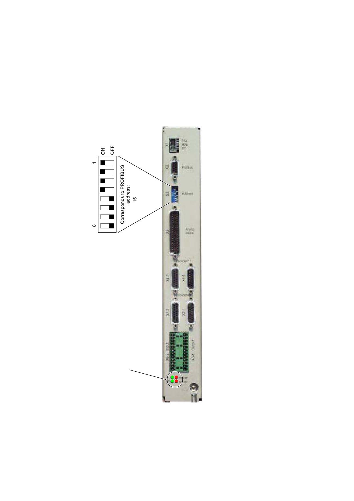
4.1
Overview of connections
;
([WHUQDO SRZHU VXSSO\
9'&
;
352),%86 FRQQHFWLRQ
6
',3 VZLWFK IRU VHWWLQJ WKH
352),%86 DGGUHVV
;
$QDORJ VHWSRLQW RXWSXWV s
9'& $[LV WR
; ದ
(QFRGHU FRQQHF
; ದ
(QFRGHU FRQQHF
WLRQ IRU $[LV
WLRQ IRU $[LV
; ದ
(QFRGHU FRQQHF
; ದ
(QFRGHU FRQQHF
WLRQ IRU $[LV
WLRQ IRU $[LV
; ದ
&RQQHFWLRQ IRU GLJLWDO
; ದ
&RQQHFWLRQ IRU GLJLWDO
LQSXW VLJQDOV
RXWSXW VLJQDOV
'LDJQRVWLFV /('V
+
3:
703
+
(;&+
5'<
&RQQHFWLRQ IRU SURWHFWLYH
JURXQG 6FUHZ 0
Figure 4-1
Overview of connections
ADI4 - Analog drive interface for 4 axes
Manual, 03/2010, 6FC5297-0BA01-0BP5
19

Hardware
4.2 Interface description
4.2
Interface description
4.2.1
Interface overview
The module has the following interfaces:
Table 4- 1
Interface overview of ADI4
Interface
Designation
Type
External +24 V power supply
X1
Plug
PROFIBUS DP
X2
Socket
PROFIBUS DP address
S2
DIP switch
Analog setpoint interface
X3
Plug
Encoder connection for Axis 1
X4-1
Socket
Encoder connection for Axis 2
X4-2
Socket
Encoder connection for Axis 3
X5-1
Socket
Encoder connection for Axis 4
X5-2
Socket
Digital outputs
X6-1
Plug
Digital inputs
X6-2
Plug
Module status
H1/H2
LEDs
4.2.2
Interface (X1): External power supply
Connection
3-pin connector MSTB 2.5/3-ST-5.08 by Phoenix
Pin assignment
Table 4- 2
Pin assignment: External power supply (X1)
Pin
Designation
Type1)
Function
1
P24EXT1
VI
External supply for module (+24 V)
2
M24EXT1
VI
Reference for external supply
3
PE
VI
Protective conductor of the external supply
1) VI: Voltage input
Connection cables
The required connecting cables must be provided by the user:
Wire, conductor cross section: 1.0 - 1.5 mm2 (AWG17 - AWG16)
ADI4 - Analog drive interface for 4 axes
20
Manual, 03/2010, 6FC5297-0BA01-0BP5

Hardware
4.2 Interface description
Supply voltage
The specifications of the supply voltage can be found in Section "Power supply (Page 35)".
4.2.3
Interface (X2): PROFIBUS DP
Connection
9-pin sub D socket
Pin assignment
Table 4- 3
Pin assignment: PROFIBUS DP (X2)
Pin
Designation
Type1)
Function
1
-
-
-
2
-
-
-
3
RxD/TxD-P
B
Receive/transmit data P (B line)
4
RTS
O
Request to Send
5
DGND
VO
Data reference potential (M5V)
6
VP
VO
Supply voltage plus (P5V)
7
-
-
-
8
RxD/TxD-N
B
Receive/transmit data N (A line)
9
-
-
-
1) VO: Voltage output
O: Output
B: Bidirectional
Connectors
● 6ES7 972-0BA41-0XA0; cable outlet 35°, without PG connection socket
● 6ES7 972-0BB41-0XA0; cable outlet 35°, with PG connection socket
Cables
● 6XV1 830-0EH10; by the meter; without trailing capability
● 6XV1 830-3EH10; by the meter; with trailing capability
Other technical data
Maximum possible data rate: 12 Mbits/s
ADI4 - Analog drive interface for 4 axes
Manual, 03/2010, 6FC5297-0BA01-0BP5
21

Hardware
4.2 Interface description
4.2.4
Interface (S2): PROFIBUS address
Setting
The PROFIBUS address of the ADI4 DP slave can only be 15 or 16 for the 802D sl and is
set via the S2 switch.
● PROFIBUS address 15: S2 switch, 1 to 4 set to ON
● PROFIBUS address 16: S2, only switch 5 set to ON
Table 4- 4
Meaning of switch S2
Switches
Meaning
1
PROFIBUS address: 20 = 1
2
PROFIBUS address: 21 = 2
3
PROFIBUS address: 22 = 4
4
PROFIBUS address: 23 = 8
5
PROFIBUS address: 24 = 16
6
PROFIBUS address: 25 = 32
7
PROFIBUS address: 26 = 64
8
Not used
NOTICE
A newly set PROFIBUS address will only come into effect after power OFF/ON.
4.2.5
Interface (X3): Analog setpoint interface
Connection
50-pin sub D connector
Pin assignment
Table 4- 5
Pin assignment: Analog setpoint interface (X3)
Pin
Designation
Type1)
Function
1
SW1
VO 3)
Setpoint of Axis 1 (±10 V)
2
BS2
VO
Reference for setpoint of Axis 2
3
SW3
VO 3)
Setpoint of Axis 3 (±10 V)
4
BS4
VO
Reference for setpoint of Axis 4
5-13
-
-
-
ADI4 - Analog drive interface for 4 axes
22
Manual, 03/2010, 6FC5297-0BA01-0BP5
Hardware
4.2 Interface description
Pin
Designation
Type1)
Function
14
RF1_1
K 2)
"Drive enable" of Axis 1, Relay Contact 1
15
RF2_1
K 2)
"Drive enable" of Axis 2, Relay Contact 1
16
RF3_1
K 2)
"Drive enable" of Axis 3, Relay Contact 1
17
RF4_1
K 2)
"Drive enable" of Axis 4, Relay Contact 1
18-33
-
-
-
34
BS1
VO
Reference for setpoint of Axis 1
35
SW2
VO 3)
Setpoint of Axis 2 (±10 V)
36
BS3
VO
Reference for setpoint of Axis 3
37
SW4
VO 3)
Setpoint of Axis 4 (±10 V)
38-46
-
-
-
47
RF1_2
K 2)
"Drive enable" of Axis 1, Relay Contact 2
48
RF2_2
K 2)
"Drive enable" of Axis 2, Relay Contact 2
49
RF3_2
K 2)
"Drive enable" of Axis 3, Relay Contact 2
50
RF4_2
K 2)
"Drive enable" of Axis 4, Relay Contact 2
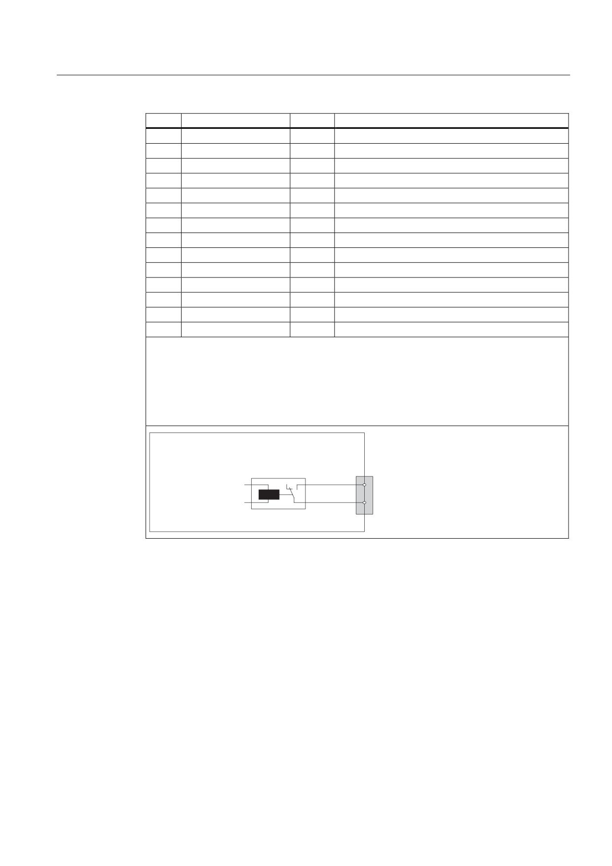
1) VO Voltage output
K Relay contact
2) Max. current carrying capacity: 2 A for 150 VDC or 125 VAC
Max. number of switching cycles:
- 24 VDC, 1 A: 107
- 24 VDC, 2 A: 105
3) Max. current carrying capacity: 10 mA (RL: 1 kW - 2 kW)
$',
;
3LQ QXPEHU
5HOD\
6LJQDO
'ULYH HQDEOH
$[LV WR
Prefabricated cables
Order no.: 6FX2 002-3AD01-⃞⃞⃞⃞
Cable length: ≤ 35 m
Information regarding the length codes is provided in:
References: /Z/ Catalog NC Z
Resolution of setpoint outputs
The analog setpoint outputs on the interface (X3) have the following resolution: 16-bit,
including sign.
ADI4 - Analog drive interface for 4 axes
Manual, 03/2010, 6FC5297-0BA01-0BP5
23

Hardware
4.2 Interface description
4.2.6
Interfaces (X4-1/X4-2/X5-1/X5-2): Encoder interfaces
Connection
15-pin SUB-D socket
Pin assignment
Pin assignment: Encoder interface of axes 1 to 4 (X4-1/X4-2/X5-1/X5-2) for incremental
encoder (TTL) and absolute encoder (SSI)
Table 4- 6
Pin assignment: Encoder interface of axes 1 to 4 (X4-1/X4-2/X5-1/X5-2) for incremental
encoder (TTL) and absolute encoder (SSI)
Pin
Designation1)
Type 2)
Function
Incremental
Absolute (SSI)
1
Unassigned
-
-
2
-
CLSx
O
SSI shift clock
3
-
CLSx_N
O
SSI shift clock inverted
4
P5MS
VO
5 V DC supply voltage
5
P24SSI
VO
24 V DC supply voltage
6
P5MS
VO
5 V DC supply voltage
7
MEXT
VO
Reference for supply voltage
8
Unassigned
-
-
9
MEXT
VO
Reference for supply voltage
10
Rx_S
-
I
Zero mark signal (Ua0)
11
XRx_S
-
I
Zero mark signal inverted (/Ua0)
12
XBx_S
-
I
Encoder signal track B inverted
(/Ua2)
13
Bx_S
-
I
Encoder signal track B (Ua2)
14
XAx_S
-
I
Encoder signal track A inverted
(Ua1)
-
DATAx_N
I
SSI data inverse
15
Ax_S
-
I
Encoder signal track A (Ua1)
-
DATAx
I
SSI data
1) x_ : Number of the encoder interface with X4-1=1, X4-2=2, X5-1=3, X5-2=4
2) VO: Voltage output
I: Signal input
O: Signal output
ADI4 - Analog drive interface for 4 axes
24
Manual, 03/2010, 6FC5297-0BA01-0BP5

Hardware
4.2 Interface description
Prefabricated cables
The following preassembled cables can be used, depending on the encoder type:
● Incremental encoder (TTL) with RS 422 and operating voltage 5 V or 24 V
Order number (MLFB): 6FX8 002-2CD01-1⃞⃞0 (5 V)
Order number (MLFB): 6FX5 002-2CD24-1⃞⃞0 (24 V)
Information on the cable lengths can be found in the "Maximum cable lengths" section.
● Absolute encoder with SSI
Order number (MLFB): 6FX8 002-2CC11-⃞⃞⃞0
Information on the cable lengths can be found in the "Maximum cable lengths" section.
● 1FT5 motor with integrated ROD320 encoder
Order number (MLFB): 6FX8 002-2CE02-1⃞⃞0
Cable length: Can be found in the "Maximum cable lengths" section.
Information regarding the length codes is provided in:
References: /Z/ Catalog NC Z
Maximum cable lengths
The maximum cable length depends on the following two parameters:
● Encoder supply voltage
Table 4- 7
Encoder supply voltage
Supply voltage: 5 V DC
Tolerance
Current consumption
Max. cable length
4.75 V - 5.25 V
≦ 300 mA
25 m
4.75 V - 5.25 V
≦ 220 mA
35 m
Supply voltage: 24 V DC
Tolerance
Current consumption
Max. cable length
20.4 V - 28.8 V
≦ 300 mA
100 m
11 V - 30 V
≦ 300 mA
300 m
ADI4 - Analog drive interface for 4 axes
Manual, 03/2010, 6FC5297-0BA01-0BP5
25

Hardware
4.2 Interface description
● Transmission frequency
Table 4- 8
Transmission frequency
Encoder type
Supply voltage
Frequency
Max.
cable length
Incremental (TTL)
5 V
1 MHz
10 m
500 kHz
35 m
24 V
500 kHz
150 m
Absolute (SSI)
24 V
1.5 Mbit/s
10 m
187.5 kbit/s
250 m
Note
If cable lengths longer than 25 m or 35 m are needed for incremental encoders, encoder
types with a 24 V DC supply voltage can be used instead.
CAUTION
To ensure error-free transmission of encoder data, do not exceed the maximum cable
lengths shown in these tables.
Encoder supply voltages
The encoder supply voltages must comply with the following specification:
Table 4- 9
Specification of encoder supply voltages
Supply voltage1)
P5MS
P24SSI
Voltage
Minimum
4.75 V
20.4 V
nominal
5 V
24 V
Maximum
5.25 V
28.8 V
Ripple
Maximum
50 mVpp
3.6 Vpp
Current load
Per encoder connection
0.3 A
Maximum
1.35 A
1 A
1) P5MS: Supply voltage for encoder (+5 V DC)
P24SSI: Supply voltage for encoder (+24 V DC)
ADI4 - Analog drive interface for 4 axes
26
Manual, 03/2010, 6FC5297-0BA01-0BP5
Hardware
4.2 Interface description
Connectable measuring systems
Incremental encoder (TTL)
● Differential transmission with RS 422 and operating voltage 5 V or 24 V
- Track A as true and inverted signal (Ua1, /Ua1)
- Track B as true and inverted signal (Ua2, /Ua2)
- Zero signal N as true and inverted signal (Ua0, /Ua0)
● Maximum output frequency: 1.5 MHz
● Phase shift of track A to track B: 90°±30°
● Current consumption: max. 300 mA
● Encoders with distance-coded zero marks/reference marks are not generally enabled.
Absolute value encoder (SSI)
● Transmission method: Synchronous serial interface (SSI) according to RS 485 with 5 V
differential signal transmission (RS 422 standard):
- Output signal: Data as true and inverted signal
- Input signal: Shift clock as true and inverted signal
● "Christmas tree" output format for rotary encoders
● Resolution: max. 25 bits
● Maximum transmission frequency: 1 Mbit/s
● Current consumption: max. 300 mA
(SINUMERIK 802D sl)
● Absolute value encoder (SSI)
The use of absolute encoders (SSI) has not been released.
(SINUMERIK 840Di sl)
● Linear encoder with distance-coded zero marks / reference marks
The following linear encoders with distance-coded zero marks / reference marks have been
released for ADI4:
● Heidenhain: LS 476 C
● Heidenhain: LS 186 C,
in conjunction with external pulse-shaping electronics (EXE), e.g. IBV 610
Note
Encoders with SINE/COSINE signals (1 Vpp) can be connected using external pulse
shaping electronics (EXE), which convert the signals to the 5 V TTL level.
ADI4 - Analog drive interface for 4 axes
Manual, 03/2010, 6FC5297-0BA01-0BP5
27

Hardware
4.2 Interface description
4.2.7
Interface (X6-1): Digital outputs
Connection
Two 12-pin connectors FK-MCP 1.5/15-ST-3.81 by Phoenix
Pin assignment
Table 4- 10 Pin assignment: Digital output interface (X6-1)
Pin
Designation
Type
Function
1)
1
P24EXT2
VI
ext. 24 V DC supply voltage
2
Q0
DO
Digital output signal 1
3
Q1
DO
Digital output signal 2
4
Q2
DO
Digital output signal 3
5
Q3
DO
Digital output signal 4
6
DIR1
DO
Digital output signal 5 or directional signal of axis 13)
7
DIR2
DO
Digital output signal 6 or directional signal of axis 23)
8
DIR3
DO
Digital output signal 7 or directional signal of axis 33)
9
DIR4
DO
Digital output signal 8 or directional signal of axis 43)
10
RDY1
K 2)
"Ready" signal of relay contact 1
11
RDY2
K 2)
"Ready" signal of relay contact 2
12
MEXT2
VI
Reference of the external supply voltage
ADI4 - Analog drive interface for 4 axes
28
Manual, 03/2010, 6FC5297-0BA01-0BP5
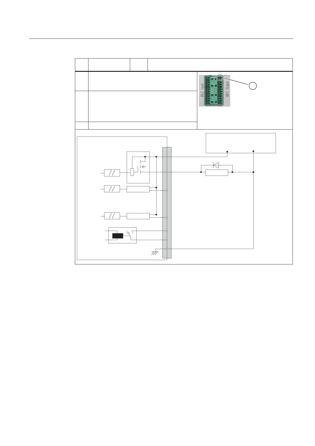
Hardware
4.2 Interface description
Pin
Designation
Type
Function
1)
1)
VI: Voltage input
DO: Digital output (24 V)
K: Relay contact
2)
Max. current carrying capacity: 2 A for 150 V DC
or 125 V AC;
Max. number of operating cycles:
- 24 V DC, 1 A: 107
① PIN 1
- 24 V DC, 2 A: 105
3)
For "unipolar spindle" function (or unipolar motor)
; ದ
([W SRZHU VXSSO\
$',
3LQ QXPEHU
9 VWDELOL]HG
9
9
3
(;7
2SWRFRXSOHU
5HOD\
'ULYHU
'ULYHU
'ULYHU
5HOD\
6LJQDO
ಯ5HDG\ರ
0(;7
0
(SINUMERIK 802D sl)
The signals from pins 2...9 are not available on an ADI4 module connected to SINUMERIK
802D sl.
Supply voltage
To supply the digital outputs with power, an external 24 V DC voltage source must be
connected to X6-1, pin 1 (P24EXT2).
The reference ground of the external voltage source must be connected with X6-1, pin 15
(MEXT2).
Further data can be found in the "Technical data" section.
ADI4 - Analog drive interface for 4 axes
Manual, 03/2010, 6FC5297-0BA01-0BP5
29

Hardware
4.2 Interface description
Electrical specification
Table 4- 11 Electrical specification of the digital outputs
Digital outputs
min.
Typical
max.
nominal
1)
Voltage for high-level (VH)
VCC - 3 V
VCC
24 V
Output current IOUT
-
-
500 mA
-
Voltage for low level (VL)
-
-
-
0 V
Leakage current at low level
-
50 µA
400 µA
-
Signal delay TPHL, TPLH 2)
-
0.5 ms
-
-
Supply voltage of the dig. outputs
1) Typical output voltage: VCC - IOUT *RON - 0.65 V
VCC: Actual operating voltage P24EXT2
Max. output current IOUT: 500 mA
Max. short-circuit current: 4 A (max. 100 µs, VCC = 24 V)
Internal resistance RON: 0.4 Ω
2) The PROFIBUS communication time as well as the application cycle time must also be taken into
account.
Incorrect connection causes neither high level nor destruction of the outputs.
General electrical properties
● Galvanic isolation using optocouplers
● Current limitation to a maximum of 500 mA
● Protection against: short-circuit, overtemperature, and loss of ground
● Automatic disconnection in case of undervoltage
Relay contact: "Ready" signal
The relay contact remains/is opened if the module is in one of the following states:
● Initialization of the module after Power ON
● Power failure or hardware interrupt (NMI)
● No cyclic communication to the DP master
● PLL error
● Synchronization error
● Overtemperature
The relay contact is closed if both conditions are present:
● Module status "Ready"
● Cyclic communication with the DP master
ADI4 - Analog drive interface for 4 axes
30
Manual, 03/2010, 6FC5297-0BA01-0BP5

Hardware
4.2 Interface description
Connecting cable
The required connecting cables must be provided by the user:
● Supply voltage X6-1, pins 1 and 12 (P24EXT2):
Wire, conductor cross-section of 1.5 mm2 (AWG16)
● Digital outputs X6-1, pins 2...9:
Wire, conductor cross-section 0.5 to 1.5 mm2 (AWG20 - AWG16)
● Ready X6-1, pins 10 and 11:
Wire, conductor cross-section of 1.5 mm2 (AWG16)
NOTICE
The maximum length of the digital signal cable is 30 m.
See also
Technical data (Page 39)
4.2.8
Interface (X6-2): Digital inputs
Connection
Two 12-pin connectors FK-MCP 1.5/15-ST-3.81 by Phoenix
Pin assignment
Table 4- 12 Pin assignment: Digital input interface (X6-2)
Pin
Designation
Type 1)
Function
1
P24OUT
VI
24 V DC supply voltage
2
BERO1
DI
Input signal of BERO / external zero mark 1
3
BERO2
DI
Input signal of BERO / external zero mark 2
4
BERO3
DI
Input signal of BERO / external zero mark 3
5
BERO4
DI
Input signal of BERO / external zero mark 4
6
MEPU1
DI
Measuring signal, probe 1 (see "Measuring probe" below)
7
MEPU2
DI
Measuring signal, probe 2 (see "Measuring probe" below)
8
DRV1_RDY
DI
"Drive Ready" signal of axis 1
9
DRV2_RDY
DI
"Drive Ready" signal of axis 2
10
DRV3_RDY
DI
"Drive Ready" signal of axis 3
11
DRV4_RDY
DI
"Drive Ready" signal of axis 4
12
MOUT
VI
Reference of the supply voltage
ADI4 - Analog drive interface for 4 axes
Manual, 03/2010, 6FC5297-0BA01-0BP5
31
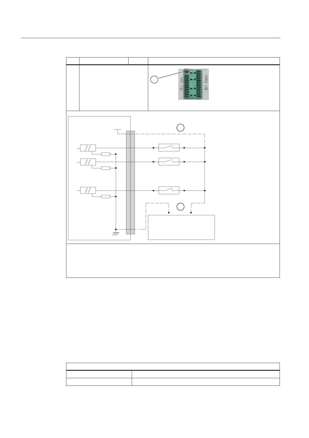
Hardware
4.2 Interface description
Pin
Designation
Type 1)
Function
1)
VI: Voltage Input
DI: Digital input (24 V)
① PIN 1
; ದ
$',
3
287
3LQ QXPEHU
'&
9
2SWRFRXSOHU
9
9
3
287H[W
([W SRZHU VXSSO\
9 VWDELOL]HG
0
① Connection if the internal supply voltage P24OUT is used;
the connection in accordance with ② is no longer required.
② Connection if an external supply voltage P24OUText is used;
the connection in accordance with ① is no longer required.
(SINUMERIK 802D sl)
On an ADI4 module in connection with SINUMERIK 802D sl, the signal: "Measuring signal,
probe 2" (pin 7) is not available.
Internal supply voltage P24OUT
Specification of the internal supply voltage P24OUT available at X6-2, pin 1 for the digital
inputs:
Table 4- 13 Specification of the supply voltage P24OUT
Voltage
Minimum
20.4 V
Nominal
24 V
ADI4 - Analog drive interface for 4 axes
32
Manual, 03/2010, 6FC5297-0BA01-0BP5

Hardware
4.2 Interface description
Voltage
Maximum
28.8 V
Ripple
Maximum
3.6 Vpp
Current load
Typical
0.1A
Maximum
1A
Power consumption
Typical
3.02 W
Maximum
30.2W
Insulation Class
A, in accordance with DIN 57110b
Typical output voltage:
VCC - IOUT * RON - 0.65 V
VCC: Actual P24OUT operating voltage
Max. output current IOUT: 1 A
Internal resistance RON: 0.4 Ω
The supply voltage P24OUT is short-circuit proof.
External supply voltage P24OUText
If an external supply voltage is used, its reference ground must be connected to X6-2,
pin 12 (M).
X6-2, pin 1 (P24OUT) then remains open.
Electrical specification
Digital inputs
min.
Typical
max.
nominal
Voltage for high-level (VH)
15 V
1)
30 V
24 V
Input current IIN at VH
3.7 mA
-
7.5 mA
-
Voltage for low level (VL)
-30 V
-
+5 V
0 V
Signal delay TPHL, TPLH 2)
-
3 µs
-
-
1) See table "Specification of the supply voltage P24OUT"
2) The PROFIBUS communication time as well as the application cycle time must also be taken into
account.
Incorrect connection causes neither high level nor destruction of the inputs.
Connecting cable
The required connecting cables must be provided by the user.
● Supply voltage X6-2, pin 1 (P24OUT), external supply voltage P24OUText:
Wire, conductor cross-section of 1.5 mm2 (AWG16)
● Digital outputs X6-2, pins 2 -11:
Wire, conductor cross-section 0.5 to 1.5 mm2 (AWG20 - AWG16)
ADI4 - Analog drive interface for 4 axes
Manual, 03/2010, 6FC5297-0BA01-0BP5
33

Hardware
4.3 Control cabinet installation
General electrical properties
● Galvanic isolation using optocouplers
● Active current limitation of the inputs
● Protection from negative input voltage
Probe
ADI4 supports only measurement of a rising or falling edge of the probe. A simultaneous
request for measurement of a rising edge and a falling edge of the probe cannot be
parameterized.
4.2.9
Interface (H1/H2): Module status
The module status is displayed on the front of the module with four diagnostic LEDs.
Table 4- 14 Diagnostic LEDs (H1/H2)
Designation
Color
Description
H1
POWER
Green
Supply voltage
LED = Off: Supply voltage not applied
LED = On: Supply voltage is applied
OVTEMP
Red
Overtemperature display
LED = Off: Device temperature < overtemperature limit
LED = On: Device temperature ≥ Overtemperature limit
H2
EXCHANGE
Green
Status: Message frame exchange with DP master
LED = Off: No message frame exchange with DP master
LED = On: Cyclic message frame exchange with DP master
READY
Red
Ready status: Message frame exchange with DP master
LED = Off: Not yet ready
LED = On: Ready
LED = Off and EXCHANGE = On: Message frame exchange active
LED = flashing: Error occurred during message frame exchange
4.3
Control cabinet installation
Installation
For high frequency interference currents, the housing of the ADI4 module must be connected
with low-resistance to the back wall of the control cabinet, and this wall in turn must be
connected with low-resistance to the motors/machines. The module should be installed on a
bare mounting wall. The connection between the mounting wall and the motors/machines
must be electrically conductive and have a large surface area. Coated cabinet walls and DIN
rails, or similar mounting means with a small contact area, do not meet this requirement.
ADI4 - Analog drive interface for 4 axes
34
Manual, 03/2010, 6FC5297-0BA01-0BP5
Hardware
4.4 Power supply
Cable routing
Power and signal cables must always be routed separately. All I/O interface (X6-1/X6-2)
signal lines should exit jointly. Single strands that are related from the signal point of view
must be twisted together. Signal cables and encoder cables should be installed separately.
All cables and lines within the control cabinet should always be placed as close as possible
to the control cabinet walls. Extended installation through open space can cause interference
injections (antenna effect). The proximity to sources of interference (contactors,
transformers, etc.) must be avoided by placing a shield plate between the cable and the
source of interference, if necessary. Cables and conductors should not be extended using
terminals or similar devices. To protect against interference injections from external sources,
signal cables must be shielded.
WARNING
The module has been designed for operation in an enclosed control cabinet. Operation
outside an enclosed control cabinet is not permissible.
4.4
Power supply
ADI4 module
To supply the ADI4 module (+24 VDC), an external power source is needed. The power
supply is connected through terminal X1 (P24EXT1) on the front panel of the ADI4 module.
Refer to Section "Overview of connections (Page 19)" for more information.
Digital outputs
To supply (+24 VDC) the digital outputs, an external power source is needed. The power
supply is connected through Terminal X6-1, Pin 1 (P24EXT2). Refer to Section "Overview of
connections (Page 19)" for more information.
Digital inputs
If the digital inputs are not supplied with the internal supply voltage of X6-2, Pin 1 (P24OUT),
this supply voltage can optionally be replaced with an external power source (+24 VDC, 1 A
maximum).
The reference ground (GND) of the external power supply source must be connected with
X6-2, Pin 12. X6-2, Pin 1 (P24OUT) remains open.
ADI4 - Analog drive interface for 4 axes
Manual, 03/2010, 6FC5297-0BA01-0BP5
35

Hardware
4.4 Power supply
Specification of the supply voltages (+24 VDC)
The external supply voltages for the ADI4 module, the digital outputs, and optionally the
digital inputs must comply with the specifications provided in the "Encoder supply voltages"
table.
Table 4- 15 Specification of the external supply voltages
Supply voltage1)
P24EXT1
P24EXT2
P24OUText
Voltage
• Minimum
18.5 V
• Nominal
24 V
• Maximum
30.2 V
Ripple
• Maximum
3.6 Vpp
Current load
• Typical
0.5 A
-
0.1 A
• Maximum
1 A
8 A
1 A
Power consumption
• Typical
12 W
-
3.02 W
• Maximum
30.2 W
241.6 W
30.2 W
1) P24EXT1: Supply voltage of the ADI4 module
P24EXT2: Supply voltage for the digital outputs
P24OUText: Optional supply voltage for the digital inputs
CAUTION
The external supply voltages must each be generated as functional extra-low voltage with
safe electrical isolation (DIN EN 60204-1, PELV).
Fuse
On the module side, supply voltages P24EXT1 and P24EXT2 must be protected against the
following:
● Overvoltage
● Short-circuit (electrical current limiting of outputs)
● Polarity reversal
● Overload
- P24EXT1: Fuse 2.5 A / 250 V
- P24EXT2: Fuse 8 A / 125 V
ADI4 - Analog drive interface for 4 axes
36
Manual, 03/2010, 6FC5297-0BA01-0BP5

Hardware
4.5 Grounding
4.5
Grounding
Grounding
The module must be installed according to EN 60204.
The user must ground each of the supply voltages. To do this, a connection must be
established from Terminal X1, Pin 2 (MEXT1) or X6-1, Pin 15 (MEXT2) to a central
grounding point of the system.
If a large-area, permanent metallic connection with the central grounding point is not
possible using the rear panel, the module must be connected to the grounding rail by means
of a wire (cross-section > 10 mm2).
CAUTION
A protective conductor must be connected. An M6 screw is provided on the lower right of
the front of the housing to connect the protective conductor. See Chapter "Dimension
drawing (Page 38)".
ADI4 - Analog drive interface for 4 axes
Manual, 03/2010, 6FC5297-0BA01-0BP5
37
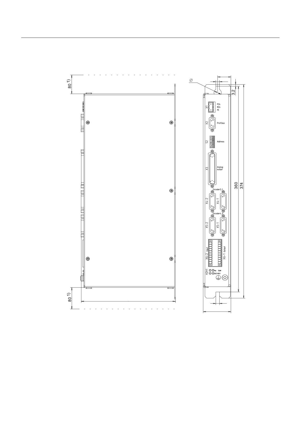
Hardware
4.6 Dimension drawing
4.6
Dimension drawing
Figure 4-2
Dimension drawing: ADI4
1)
Necessary clearance to ensure sufficient ventilation
Maximum tightening torque for all screws: 0.8 Nm
ADI4 - Analog drive interface for 4 axes
38
Manual, 03/2010, 6FC5297-0BA01-0BP5