SINUMERIK 840D sl Hardware. Manual (2011-2020) - page 26
Mounting
6.2 Installation types
6.2
Installation types
Prerequisite
The Control Unit is installed in a control cabinet along with the SINAMICS components.
The following prerequisites must be met to install a Control Unit:
● The control cabinet has been installed and wired.
● SINAMICS components should already have been installed and wired (for lateral
mounting).
● Components and tools are available.
Note
The procedures described below for mounting the Control Unit refer to the delivery
condition of the Control Unit: The upper clip is pulled in and the spacers are mounted
(see figure below).
Designs
The Control Unit is compatible with the SINAMICS S120 in booksize format. There are two
possible mounting methods:
● Mounting on the rear wall of the control cabinet
● Lateral mounting on the SINAMICS S120 Line Module
In this type of mounting, the Control Unit is attached to the side wall of the Line Module in
the control cabinet.
As the design of the Control Unit is based on that of the SINAMICS S120 family, please
observe these notes and the corresponding reference documents.
Mounting aids
The Control Unit is designed for mounting in a control cabinet (IP 20 degree of protection in
accordance with general conditions).
Note
Exception: NCU 710.2 and NCU 720.2 have no cutouts for lateral mounting on the
SINAMICS drive line-up.
NCU 7x0.2
38
Manual, 02/2011, 6FC5397-0AP20-0BA0
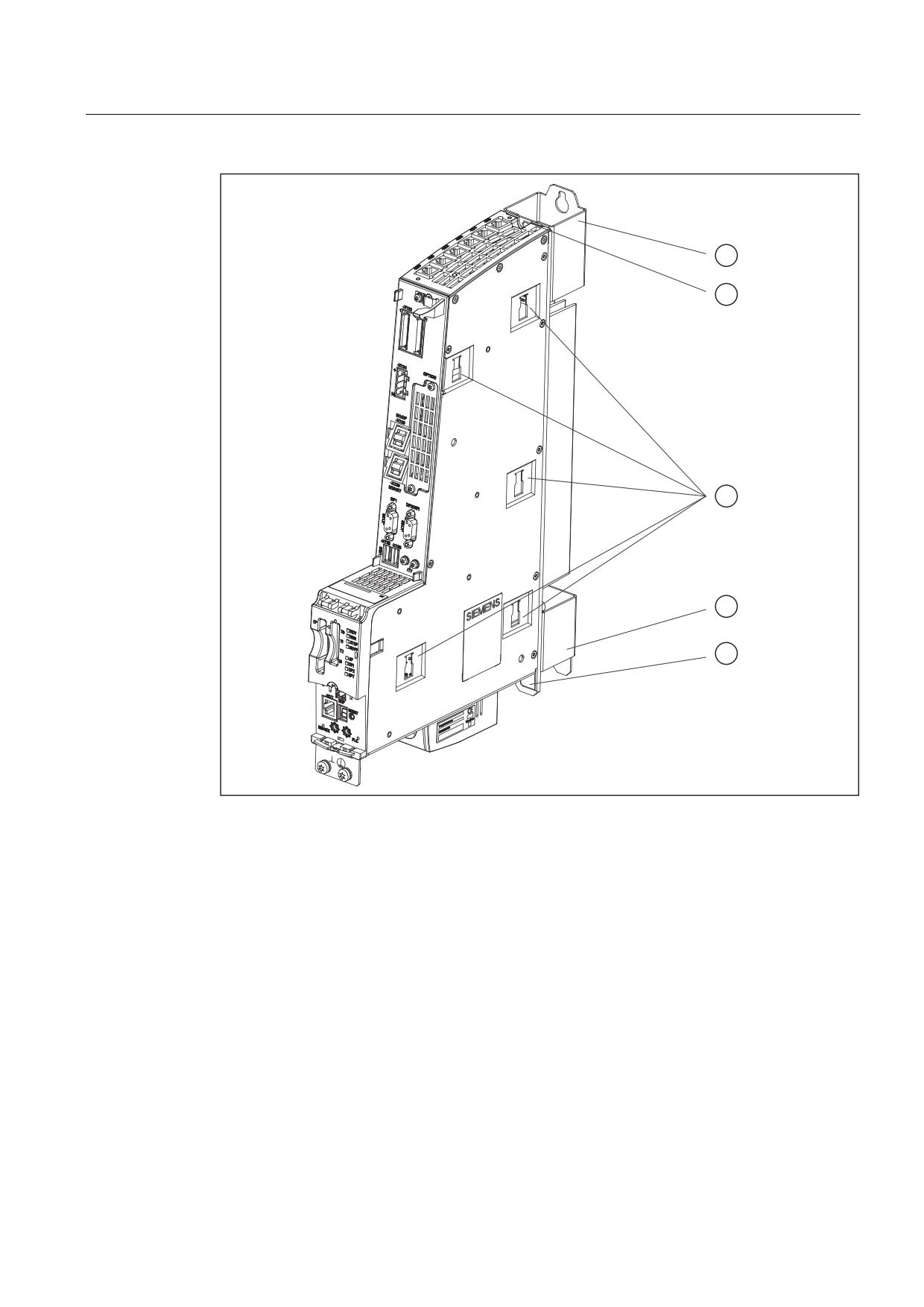
Mounting
6.2 Installation types
(1)
Spacers for mounting on the rear wall of the control cabinet
(2)
Lugs for mounting directly on the rear wall of the control cabinet (external heat dissipation)
(3)
Cutouts for lateral mounting on SINAMICS drive group
Figure 6-1
Mounting aids
Mounting instructions
A seal can be provided for segregated heat removal on the Control Unit (apart from
NCU 710.2 and NCU 720.2). This enables an air-tight connection to be made between the
Control Unit and the rear wall of the control cabinet, i.e. the cooling fins are located outside
the control cabinet.
NCU 7x0.2
Manual, 02/2011, 6FC5397-0AP20-0BA0
39
Mounting
6.3 Mounting the control unit on the rear wall of the control cabinet
6.3
Mounting the control unit on the rear wall of the control cabinet
6.3.1
Mounting control unit using spacers
Introduction
Spacers can be used to mount the control unit on a bare-metal highly-conductive rear wall of
a control cabinet. This mounting method should be used if a number of control units are
required or if you wish to isolate the Line Module spatially.
Procedure
Mount the control unit with two screws of the M6 type (6 Nm tightening torque) on the
spacers on the rear of the control cabinet.
6.3.2
Mounting the Control Unit without spacers
Introduction
If you need to disconnect control units NCU 710.2 and NCU 720.2 from the Line Module, or
simply wish to do so, you can mount them directly on the rear wall of the control cabinet
without spacers.
Procedure
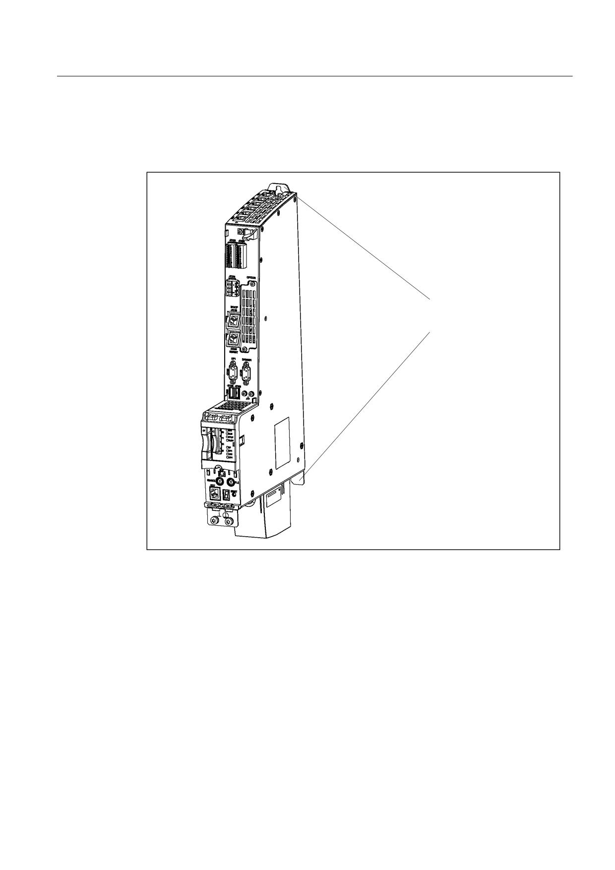
The control unit has on the rear side on the top a metallic lug that is fitted and tightened with
three torx screws of the M3 type (0.8 Nm) in its delivery state.
1. Remove the spacers with a T10 screwdriver .
2. Loosen the screws and push the clip up until the upper hole extends beyond the housing.
NCU 7x0.2
40
Manual, 02/2011, 6FC5397-0AP20-0BA0
Mounting
6.3 Mounting the control unit on the rear wall of the control cabinet
3. Tighten up the three screws on the clip again.
4. Mount the top and bottom of the control unit directly on the rear wall of the control cabinet
with two M6 screws (6 Nm).
0RXQW ZLWK 0 VFUHZV
Figure 6-2
Mounting the control unit without spacers
NCU 7x0.2
Manual, 02/2011, 6FC5397-0AP20-0BA0
41
Mounting
6.3 Mounting the control unit on the rear wall of the control cabinet
6.3.3
Mounting the Control Unit for segregated heat removal
Introduction
If you wish to perform segregated heat removal on the NCUs with cooling fins, the NCUs can
be mounted directly on the rear wall of the control cabinet without spacers.
Prerequisites
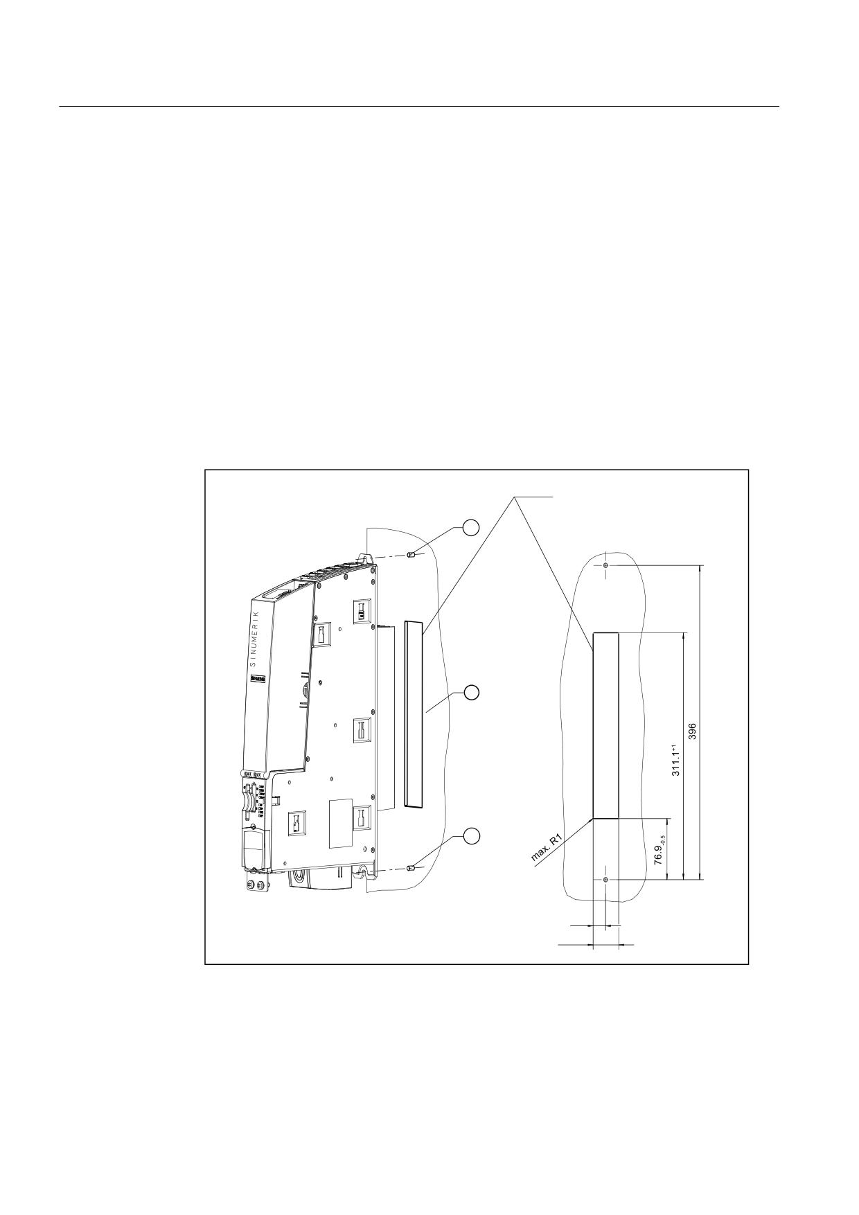
● The bushing for the cooling ribs (external heat sink) has been fitted in the rear wall of the
control cabinet.
● Please ensure the area around the seal is both smooth and clean (② please see figure
titled "Panel cutout").
● The spacer and the lugs are secured with M3 torx screws. You need a T10 screwdriver
for screwing; tightening torque 0.8 Nm.
&XW RXW IRU KHDW VLQN HOHPHQW
GXULQJ VHJUHJDWHG KHDW UHPRYDO
Figure 6-3
Panel cutout
NCU 7x0.2
42
Manual, 02/2011, 6FC5397-0AP20-0BA0
Mounting
6.3 Mounting the control unit on the rear wall of the control cabinet
Procedure
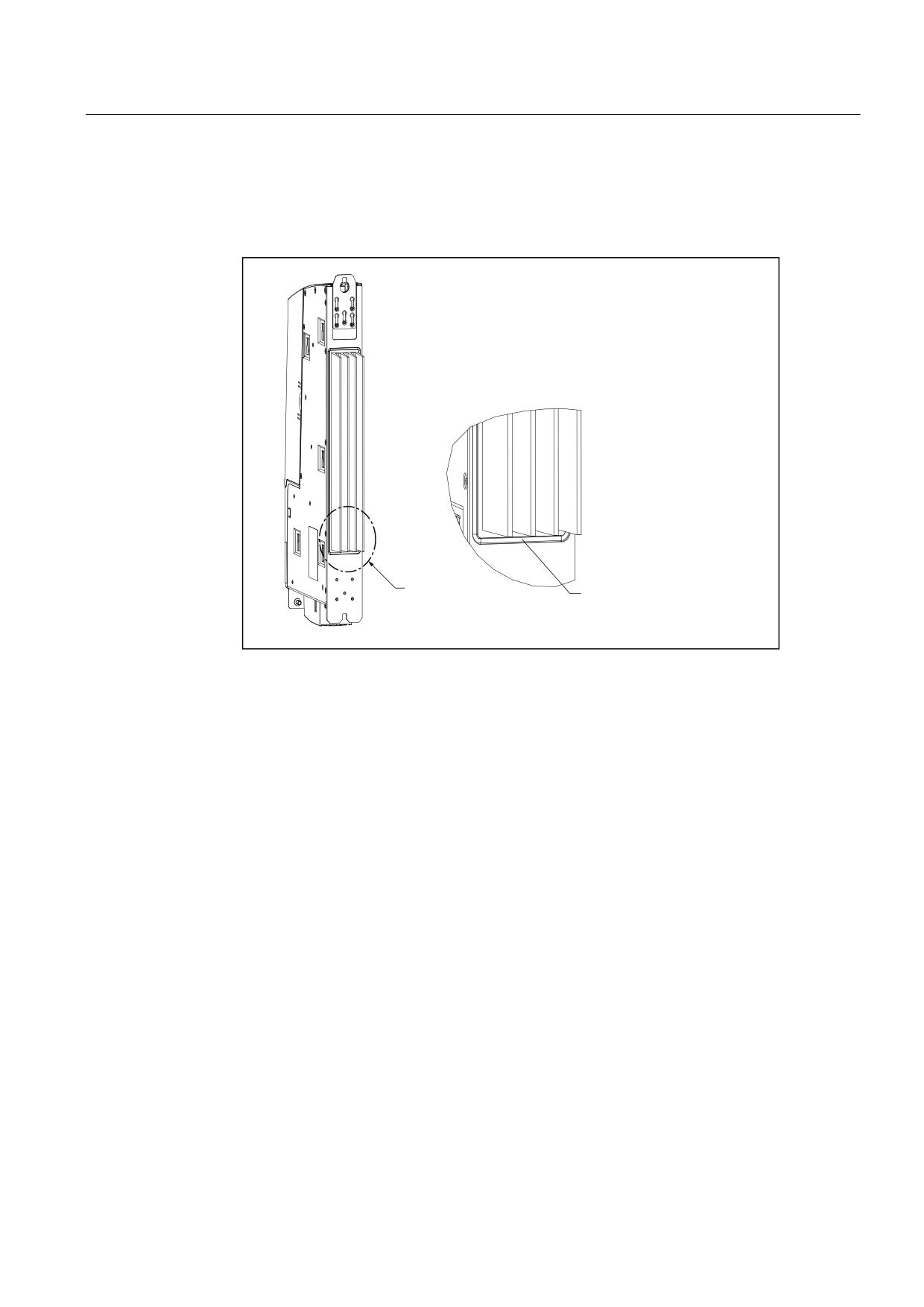
1. Remove the spacers.
2. Fit the seal around the cooling fins of the control unit.
3ODFH WKH VHDO IRU VHJUHJDWHG KHDW
$
UHPRYDO
)&
$$
$$
$
LQ WKH KHDW VLQN VORW
3. Loosen the three M3 screws on the upper clip and push the clip up until the upper hole
protrudes beyond the housing.
4. Tighten up the three screws on the clip again.
5. Mount the top and bottom of the control unit with heat sink directly on the rear wall of the
control cabinet using two M6 screws (6 Nm) (① see figure titled "Panel cutout").
See also
Variants (Page 16)
NCU 7x0.2
Manual, 02/2011, 6FC5397-0AP20-0BA0
43
Mounting
6.4 Lateral mounting of Control Unit on the SINAMICS drive line-up
6.4
Lateral mounting of Control Unit on the SINAMICS drive line-up
Introduction
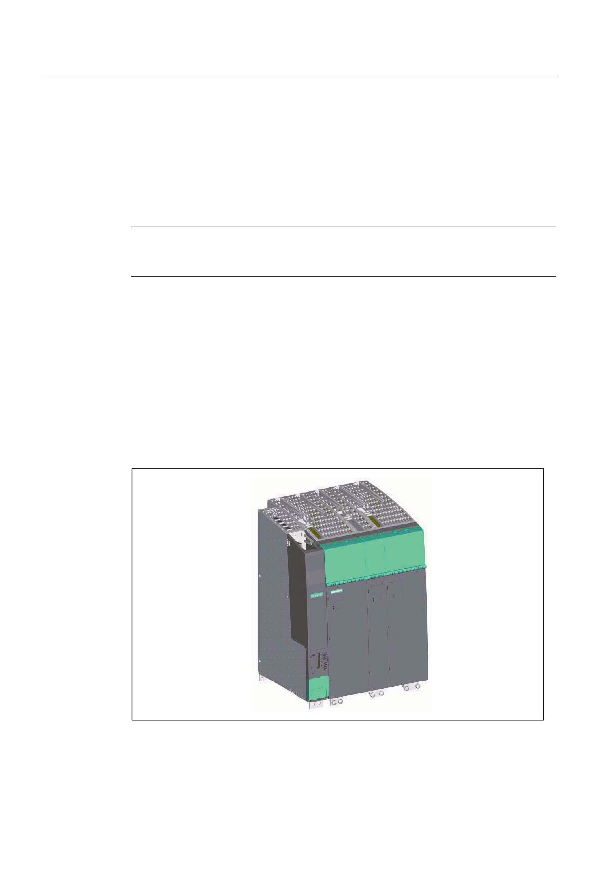
The Control Unit can also be mounted laterally on the SINAMICS drive line-up, on the side
panel of a SINAMIC S120 Line Module. The required mounting elements are supplied with
the Line Module.
Note
Exception: NCU 710.2 and NCU 720.2 cannot be laterally mounted on the SINAMICS drive
line-up.
Proceed as follows
The Line Module has five mounting elements on the left-hand side. To mount the Control
Unit, proceed as follows:
1. Remove the spacers from the Control Unit.
2. Position the Control Unit on the left-hand side of the Line Module. The mounting fixtures
fit exactly in the five cutouts on the Control Unit.
3. Push the two units together.
4. Press down on the Control Unit until it engages and is securely connected to the Line
Module.
Figure 6-4
SINAMICS group with Control Unit
NCU 7x0.2
44
Manual, 02/2011, 6FC5397-0AP20-0BA0
Connecting
7
7.1
Overview
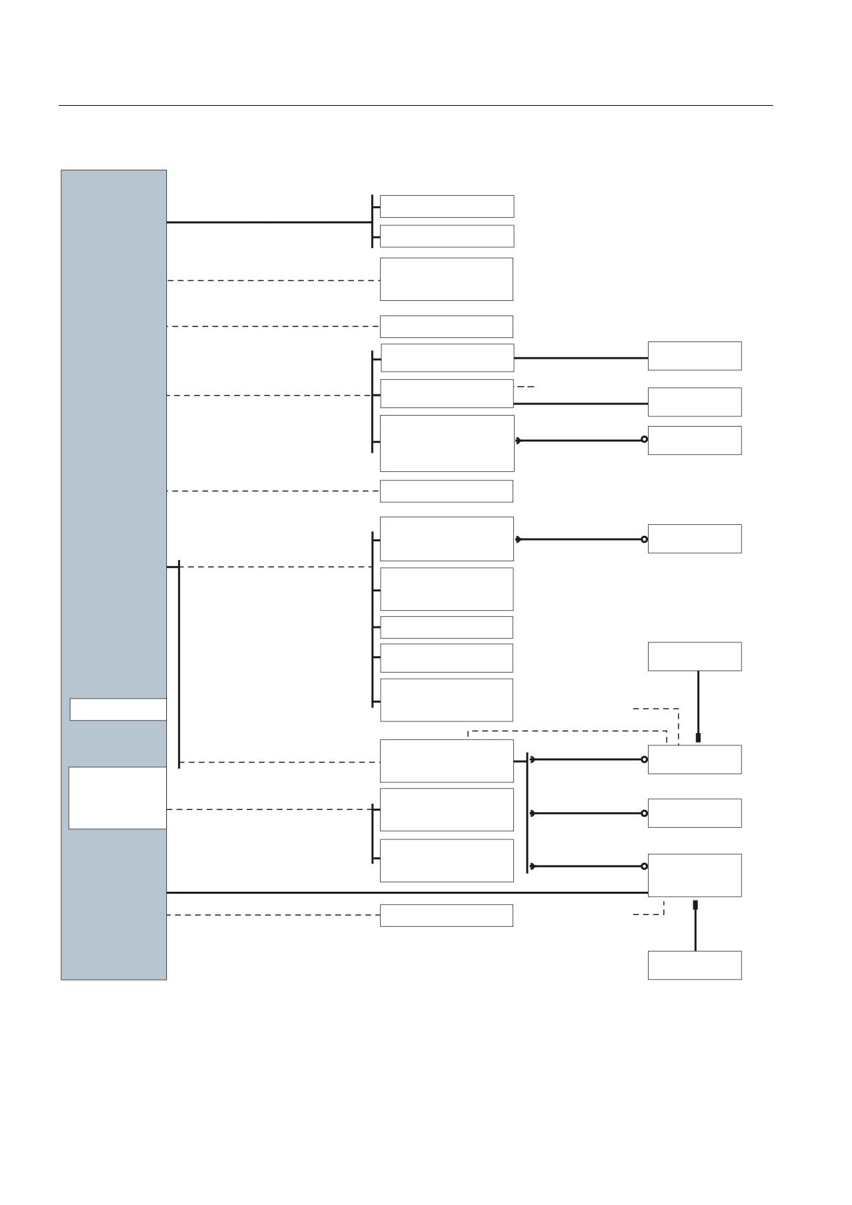
Connection options
The control unit has a series of interfaces via which the power supply and the remaining
system components are connected. The front cover on the control unit must be open to
make the connections.
● The various SINAMICS components are connected with the control unit via DRIVE-CLiQ.
● Actuators and sensors can be connected to the digital inputs/outputs.
● The control units have the following communication options:
- PROFIBUS DP, MPI, Ethernet
- PROFINET with NCU 720.2 PN and NCU 730.2 PN
The following overview shows an example of the various interfaces and their connection
options.
Note
All devices in the SINUMERIK 840D sl and SINAMICS S120 product families appear in
Catalog NC 61. SIMATIC products that can be connected to the control unit appear in
Catalog PM 10.
NCU 7x0.2
Manual, 02/2011, 6FC5397-0AP20-0BA0
45
Connecting
7.1 Overview
2UGHU 1R
6,180(5,.
3UH DVVHPEOHG FDEOH
' VO
1&8
'5,9( &/L4 FDEOH
6,1$0,&6 6
'5,9( &/L4
;
VHH 027,21 &211(&7
;
;
1;
1;
;
;
;
GLJLWDO LQSXWV DQG
'LJLWDO , 2
;
GLJLWDO
'LJLWDO , 2
;
LQSXWV RXWSXWV
9 '&
;
3RZHU VXSSO\
6,180(5,.
,QFOXGHG LQ
6,180(5,.
7&8 3&8
2SHUDWRU SDQHO IURQW
VFRSH RI VXSSO\
(PHUJ VWRS HQDEOLQJ FLUFXLW
(WKHUQHW FDEOH
&RQQHFWLRQ ER[
(WKHUQHW
;
6,180(5,.
FRQQHFWLRQ PRGXOH 31
;9
%
+7
+7
)&
$$
$$
6,180(5,.
);
&3
0&3
& 31 0&3
31
(OHFWURQLF
0&3
& 31 0&3
31
ืb
P
KDQGZKHHO
033
,(
(WKHUQHW FDEOH
(WKHUQHW
;
)DFWRU\ QHWZRUN
6,180(5,.
);
&3
(OHFWURQLF
0&3
& 0&3
KDQGZKHHO
0&3
033
ืb
P
352),%86 FDEOH
352),%86
;
8S WR &1& 6: YHUVLRQ
'3
6,1$0,&6 6
2QO\ IRU SRVLWLRQLQJ WDVNV YLD 3/&
0RWRU 0RGXOH
YLD &8
)URP &1& 6: YHUVLRQ
63
,VRFKURQRXV PRGH SRVVLEOH
[ LVRFKURQRXV
RU [ LVRFKURQRXV
[ QRQ LVRFKURQRXV
$',
33b
0LQLDWXUH
86%
;
, 2bPRGXOH
++8
;
,QFOXGHG LQ
6,0$7,&
VFRSH RI VXSSO\
,2
(PHUJ VWRS HQDEOLQJ
&) FDUG
;
352),%86 '3
FLUFXLW
3/& LQSXWV
+DQGZKHHO
);
&3
&RQQHFWLRQ NLW
FRQQHFWLRQ
ืb
P
);
%*
PRGXOH
352),1(7 SRUW
3RUW
6,1$0,&6 6
3RUW
);
&3
(OHFWURQLF
0RWRU 0RGXOH
2SWLRQ VORW
3RUW
KDQGZKHHO
YLD &8
ZLWK &%(
ืb
P
0HDV
;
VRFNHWV
;
6,1$0,&6
;
);
&3
,2
'LVWULEXWLRQ OLVW
;
352),1(7 ,2
ืb
P
++8
352),%86 '3 03,
352),%86 FDEOH
03, W\SH
;
)RU 03, FDEOH VHH 027,21 &211(&7
(PHUJ VWRS HQDEOLQJ FLUFXLW
(WKHUQHW
;
3URJUDPPLQJ GHYLFH 3'
,QFOXGHG LQ
VFRSH RI VXSSO\
2PLWWHG ZKHQ FRQQHFWLQJ KDQGZKHHO YLD 0&3 RU 033
56
&
;
2QO\ IRU SRVLWLRQLQJ WDVNV YLD 3/&
6HUYLFH
+DQGKHOG XQLW
2QO\ IRU 1&8
1&8
31 1&8
1&8
31
W\SH % 03,
)RU 1&8
31 1&8
31 DVVLJQHG ZLWK 352),1(7 3RUW DQG
Figure 7-1
Connection options for a control unit
NCU 7x0.2
46
Manual, 02/2011, 6FC5397-0AP20-0BA0

Connecting
7.2 Safety information for wiring
Interface overview
Table 7- 1
Overview of available external interfaces
Interface
Designation
Connector type
DRIVE-CLiQ (1)
X100
Spec. RJ45 socket
DRIVE-CLiQ (2)
X101
Spec. RJ45 socket
DRIVE-CLiQ (3)
X102
Spec. RJ45 socket
DRIVE-CLiQ (4)
X103
Spec. RJ45 socket
DRIVE-CLiQ (5)
X104 (only NCU 720/730)
Spec. RJ45 socket
DRIVE-CLiQ (6)
X105 (only NCU 720/730)
Spec. RJ45 socket
Ethernet IE1/OP
X120
Standard RJ45 socket
Ethernet IE2/NET
X130
Standard RJ45 socket
Ethernet (service socket)
X127
Standard RJ45 socket
PROFINET
Port 1 (only "PN NCUs")
Standard RJ45 socket
Port 2 (only "PN NCUs")
Standard RJ45 socket
Digital inputs/outputs
X122, X132
Screw terminals, 2x12-pin
24 V power supply
X124
Screw terminals, 4-pin
USB interfaces
X125, X135
USB socket
PROFIBUS DP1
X126
9-pin SUB-D socket
PROFIBUS DP2/MPI
X136
9-pin SUB-D socket
RS232
X140
9-pin SUB D plug connector
Measuring sockets (T0, T1, T2,
X131 - X134
Sockets on the printed-circuit
and G)
board
CompactFlash Card
X109
50-pin socket
Dual fan/battery module
X190
6-pin
7.2
Safety information for wiring
Note the following:
Safety information
DANGER
The system power supply must be disconnected when you wire the control unit.
NOTICE
If your axis grouping contains a Smart Line Module without DRIVE-CliQ (5 kW or 10 kW),
you must assign the Smart Line Module enable signal to digital output X122.1 on the
control unit.
NCU 7x0.2
Manual, 02/2011, 6FC5397-0AP20-0BA0
47
Connecting
7.3 Opening the front cover
7.3
Opening the front cover
Introduction
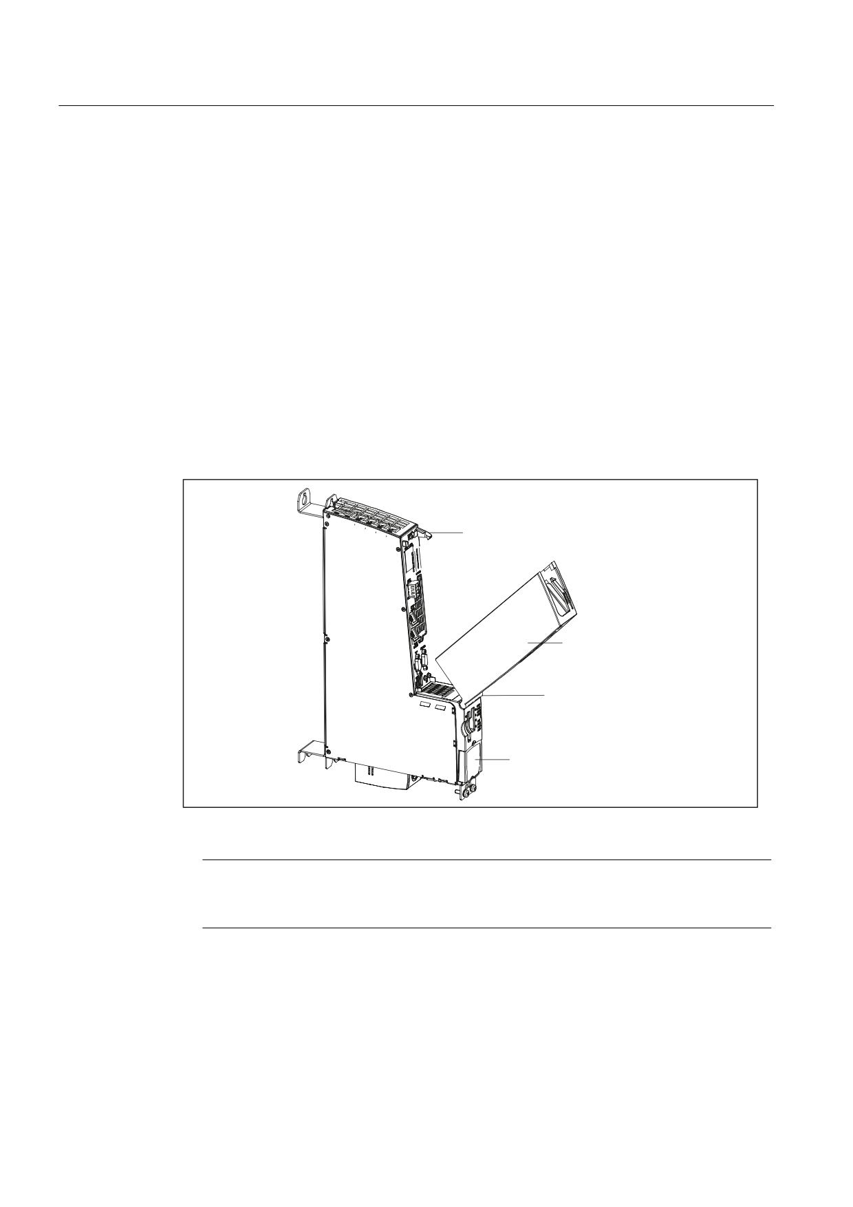
The interfaces are concealed behind a front cover. You must remove this cover before you
can wire the interfaces.
A hinge connects the front cover to the front of the housing. Once opened, the cover can be
completely removed. When the front cover is closed (flipped up), it automatically locks into
place by means of a hook on the connector panel.
Procedure
1. Disengage the release hook on the inside of the front cover (the front cover is open and
in the up position).
2. Remove the front cover with a forward motion.
+RRN
)URQW FRYHU
3LYRWLQJ KLQJH
%ODQNLQJ FRYHU
Figure 7-2
Removing the front cover
Note
All cables must be routed vertically upwards to the fullest extent possible so that the front
cover can be closed. The front cover is open and in the up position.
NCU 7x0.2
48
Manual, 02/2011, 6FC5397-0AP20-0BA0
Connecting
7.4 Power supply
7.4
Power supply
7.4.1
Application
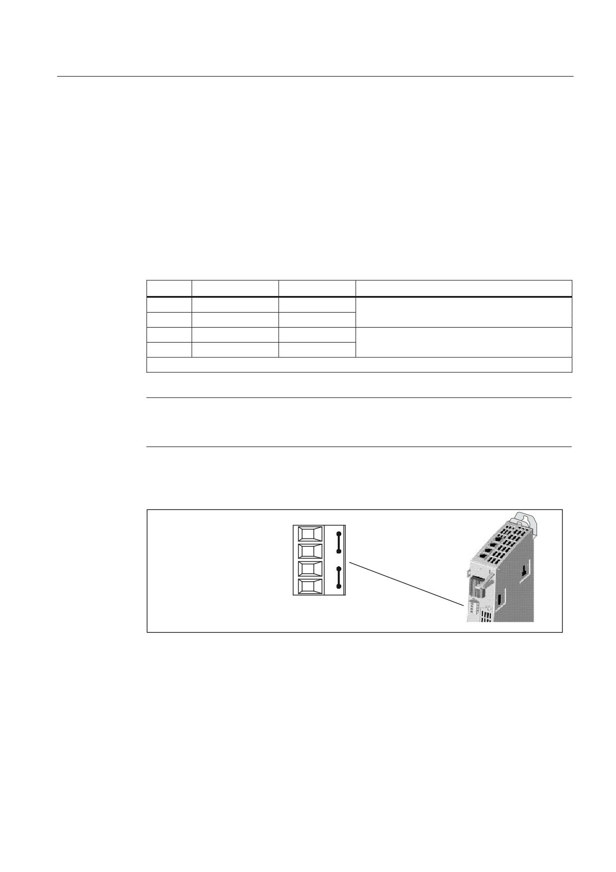
This interface is provided exclusively for connection of the external power supply.
Pin assignment
Table 7- 2
Power supply X124
Pin
Signal name
Signal type
Meaning
+
P24
VI
Power supply 24 V
+
P24
VI
G
G
VO
Ground
G
G
VO
Signal type: VI = voltage input;VO = voltage output
Note
The two "+" or "G" terminals are jumpered in the connector. This ensures the 24 V voltage is
looped through.
Position of power supply interface
3RZHU VXSSO\ FRQQHFWRU
0
$OUHDG\ SOXJJHG LQ ZKHQ SURGXFW LV VKLSSHG
Figure 7-3
Power supply interface
NCU 7x0.2
Manual, 02/2011, 6FC5397-0AP20-0BA0
49

Connecting
7.4 Power supply
7.4.2
Requirements for the power supply
External 24 V power supply
Power is supplied to the Control Unit by an external 24 V power supply (e.g., SITOP). The
following power consumption values for the Control Units provide a configuration basis for
calculating the 24 V DC power supply.
Table 7- 3
Input voltage specification
Parameters
Values
Typ. power consumption 1)
2.0 A
Max. power consumption 2)
8.5 A
1) NCU only (processor, memory, etc.)
2) NCU with full load at all outputs (digital outputs, USB, DRIVE-CliQ, PROFIBUS DP etc.)
Requirements of DC power supplies
DANGER
The DC power supply is always referenced to ground and may not be generated by an
autotransformer.
Final user interfaces are powered via a DC power supply with protective separation per EN
61800-5-1.
In the case of supply lines > 10 m, protectors must be installed at the device input in order
to protect against lightning (surge).
The DC power supply must be connected to the ground/shield of the Control Unit for EMC
and/or functional reasons. For EMC reasons, this connection should only be made at one
point. As a rule, the connection is provided as standard in the S7-300 I/Os. In exceptional
circumstances when this is not the case, the ground connection should be made on the
grounding rail of the control cabinet; please also refer to /EMC/EMC Installation Guide.
NCU 7x0.2
50
Manual, 02/2011, 6FC5397-0AP20-0BA0

Connecting
7.4 Power supply
Table 7- 4
DC power supply requirements in accordance with EN 61131-2
Rated voltage
24 V DC
Voltage range (average value)
20.4 to 28.8 V DC
Voltage ripple peak-to-peak
5 % (unfiltered 6-pulse rectification)
Ramp-up time at power-on
Any
Non-periodic overvoltages
≤ 35 V
Duration of overvoltage
≤ 500 ms
Restoration time
≥ 50 s
Events per hour
≤ 10
Transient voltage interruptions
Outage time
≤ 3 ms
Restoration time
≥ 10 s
Events per hour
≤ 10
Additional references
Recommended power supply units and tables for calculating power consumption for
interconnection with SINAMICS S120 modules can be found in the chapter entitled Control-
Cabinet Construction and EMC Booksize in the SINAMICS S120 Booksize Power Units
Manual.
7.4.3
Connecting the power supply
Wiring the screw-type terminal block
The required 24 V DC load current supply is wired to screw-type terminal block X124.
DANGER
The 24 V direct voltage is to be configured as a protective extra low voltage - DVC A or
PELV.
Supply system lines
Table 7- 5
Cable specification for X124
Characteristics
Version
Connector type
Screw-type terminals
Connection option
Up to 2.5 mm2
Current carrying capacity
Max. 10 A
Max. cable length
10 m
NCU 7x0.2
Manual, 02/2011, 6FC5397-0AP20-0BA0
51

Connecting
7.5 DRIVE CLiQ components
Use flexible cables with a cross section of 0.25 to 2.5 mm2 (or AWG 23 to AWG 13) for wiring
the power supply.
If you only use one wire per connection, a ferrule is not required.
You can use ferrules without an insulating collar in accordance with DIN 46228, Form A long
version.
7.5
DRIVE CLiQ components
7.5.1
Application
The components of the SINAMICS S120 drive family and the Control Unit are interconnected
using DRIVE-CLiQ. When connecting the components, please follow the rules in the
documentation below without exception:
The "Connecting components" section of the "Machine Configuration Guidelines" System
Manual
Properties
● Automatic detection of components
●
24 V/450 mA per DRIVE CLiQ interface is provided for the connection of encoders and
measuring systems
DRIVE-CliQ pin assignment
Table 7- 6
DRIVE-CLiQ interface (X100 - X103 or X100 - X105)
PIN
Signal name
Signal type
Meaning
1
TXP
O
Transmit data +
2
TXN
O
Transmit data -
3
RXP
I
Receive data +
4
Reserved, do not use
5
Reserved, do not use
6
RXN
I
Receive data -
7
Reserved, do not use
8
Reserved, do not use
A
+ (24 V)
VO
Voltage supply for DRIVE-CLiQ, 450 mA maximum
B
G (0 V)
VO
Ground to 24 V
Signal type: I = Input; O = Output; VO = Voltage Output
NCU 7x0.2
52
Manual, 02/2011, 6FC5397-0AP20-0BA0
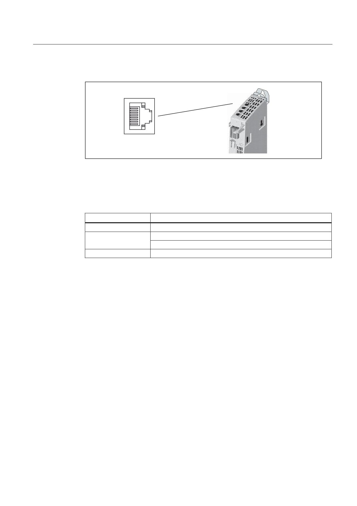
Connecting
7.5 DRIVE CLiQ components
Position of plug connectors
B
8
1
A
Figure 7-4
DRIVE-CLiQ interface
Cable specifications
Table 7- 7
Cable specifications for X100 - X103 or X100 - X105
Characteristic
Version
Connector type
RJ45 socket
Cable type
DRIVE-CLiQ standard (inside the control cabinet)
MOTION CONNECT (outside the control cabinet)
Max. cable length
70 m
NCU 7x0.2
Manual, 02/2011, 6FC5397-0AP20-0BA0
53

Connecting
7.5 DRIVE CLiQ components
7.5.2
Connectable DRIVE-CLiQ components
Components
As a rule, all SINAMICS components approved for SINUMERIK can be connected using the
DRIVE-CLiQ interface.
Table 7- 8
Components with DRIVE-CLiQ
Component
Description
NX10/15
Drive expansion module for up to 6 axes
SINAMICS S120, system components of the booksize and chassis formats
Smart / Active / Basic
Line Modules provide the central power supply to the DC link.
Line Module
Single / Double Motor
Motor Modules draw their power from the DC link to supply the
Module
connected motors.
SINAMICS S120, additional system components
SMC10/20/30
Cabinet-Mounted Sensor Modules are needed when a motor with a
DRIVE-CLiQ interface is not available and when external encoders
are required in addition to the motor encoder.
SME20/25
Measuring systems outside the cabinet can be connected directly to
the Sensor Module External.
DMC20/DME20
DRIVE-CLiQ Hub Modules are used to implement star-shaped
distribution of a DRIVE-CLiQ line.
TM15
The number of available digital inputs and outputs within a drive
system can be expanded with the Terminal Module.
Additional references
● For information on SINAMICS S120 line modules and Motor Modules, please refer to the
- Equipment Manual Booksize Power Units
- Chassis Power Units Equipment Manual
● You can find information on all other modules in the SINAMICS S120 "Control Units and
Additional System Components" Manual.
NCU 7x0.2
54
Manual, 02/2011, 6FC5397-0AP20-0BA0

Connecting
7.6 Use of Ethernet interfaces
7.6
Use of Ethernet interfaces
Application
The following connections can be established via the Ethernet interfaces:
● X120 provides the link to the system network (e.g. operator panels).
● X130 connects the control unit to the company network.
● X127 is used for commissioning and remote diagnostics via teleservice adapter IE.
You can find further details in the following manuals:
- SINUMERIK 840D sl Basesoftware and Operating Software Commissioning Manual
- SIMATIC TS Adapter IE Manual
Properties
The interfaces are full duplex 10/100 Mbit Ethernet ports. Both ports are connected as an
Ethernet terminal.
Pin assignment
Table 7- 9
Ethernet interfaces X120, X130, X127
Pin
Signal name
Signal type
Meaning
1
TX+
Output
Transmit data +
2
TX-
Output
Transmit data -
3
RX+
Input
Receive data +
4
NC
5
NC
6
RX-
Input
Receive data -
7
NC
8
NC
NCU 7x0.2
Manual, 02/2011, 6FC5397-0AP20-0BA0
55
Connecting
7.6 Use of Ethernet interfaces
LED displays
For diagnostic purposes, the RJ45 sockets are each equipped with a green and an orange
LED. This allows the following status information about the respective Ethernet port to be
displayed:
Table 7- 10 Ethernet port LED displays
LED
Status
Meaning
Green
On
10 or 100 Mbit link available
Off
Missing or faulty link
Orange
On
Receive or transmit activity
Off
No activity
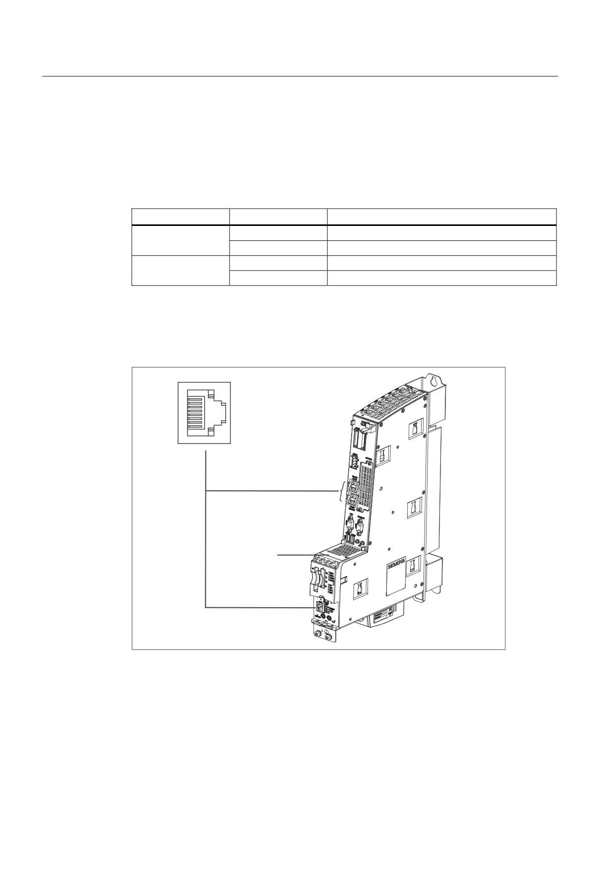
Position of connectors
The following figure shows the mounting position and designation of the Ethernet connectors
on the module.
;
;
$GKHVLYH ODEHO ZLWK
0$& DGGUHVVHV
;
Figure 7-5
Position of the Ethernet interfaces
NCU 7x0.2
56
Manual, 02/2011, 6FC5397-0AP20-0BA0
Connecting
7.6 Use of Ethernet interfaces
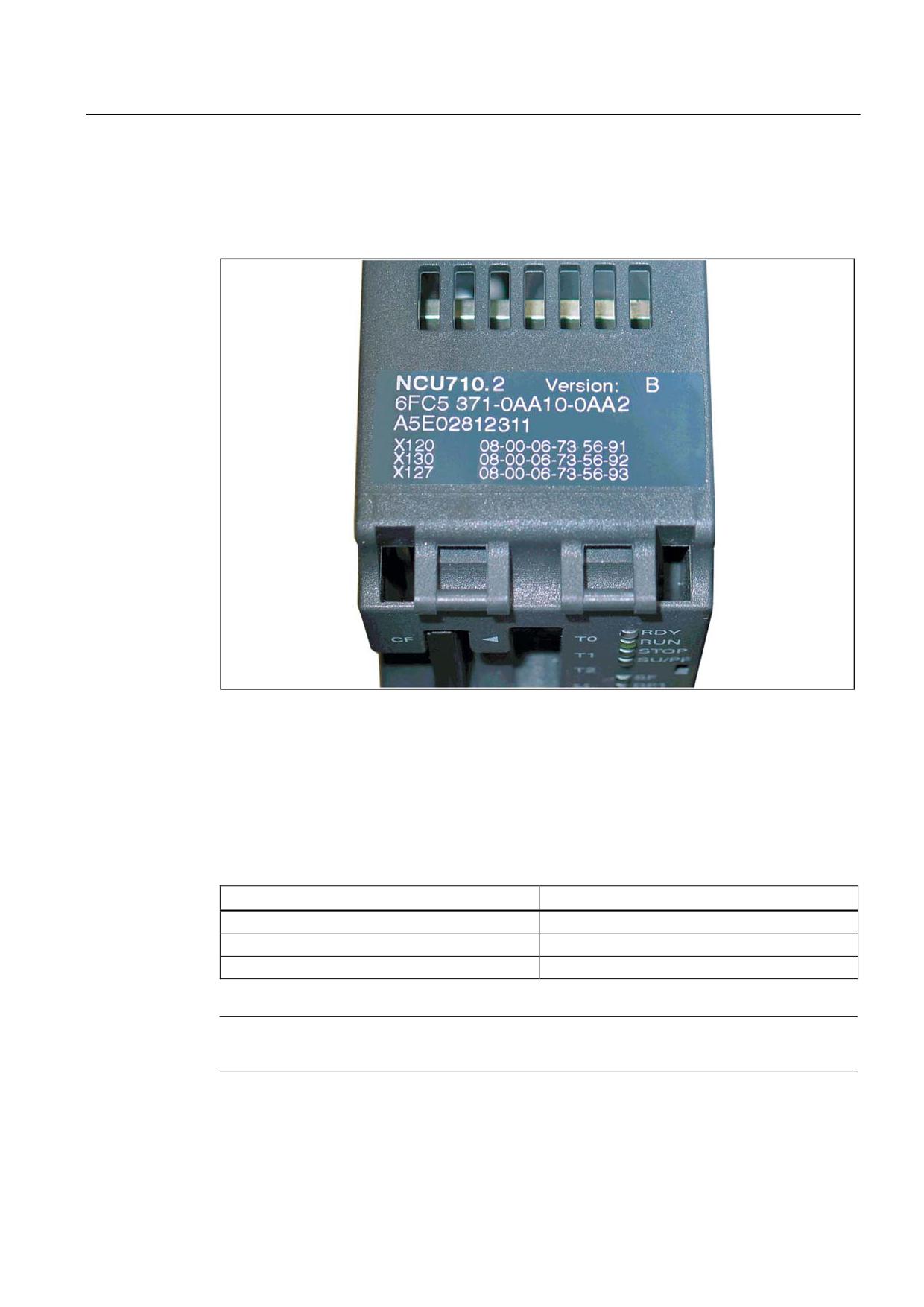
MAC addresses
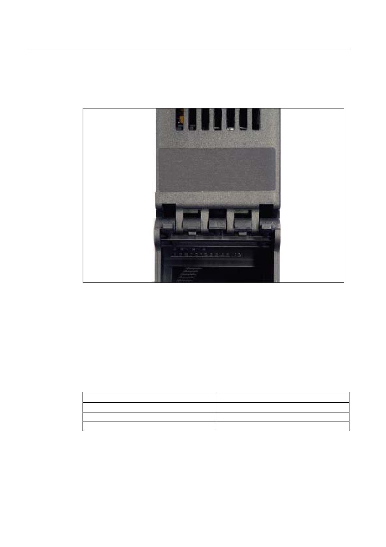
A type plate for the MAC addresses of the Ethernet interfaces is attached to the front panel
of the control unit:
Figure 7-6
MAC addresses of Ethernet interfaces X120, X130, X127
You can see this type-plate when you open the front cover of a control unit without
PROFINET.
Cable specification
Table 7- 11 Cable specification for X120, X130, and X127
Characteristic
Version
Connector type
RJ-45 jack
Cable type
Industrial Ethernet cable (CAT5)
Max. cable length
100 m
Note
A crossover cable is required for the direct link between the control unit and the TCU.
NCU 7x0.2
Manual, 02/2011, 6FC5397-0AP20-0BA0
57
Connecting
7.7 PROFINET
7.7
PROFINET
7.7.1
Application
Prerequisite
For SINUMERIK 840D sl, a PROFINET system can only be installed with the following
control units:
● NCU 720.2 PN
● NCU 730.2 PN
Application
The following communication links can be established via PROFINET interfaces:
● PROFINET CBA:
Communication between controllers as components in distributed systems
● PROFINET IO:
Communication between the PLC controller and field devices
- No access from NCK to PROFINET I/O
- No support from isochronous mode (PROFINET IRT)
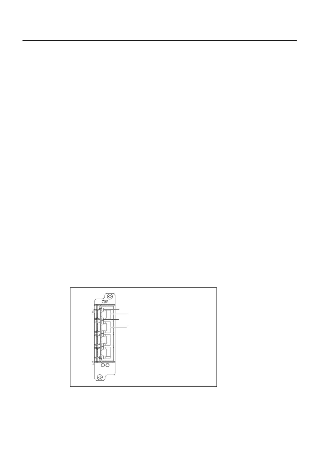
Properties
The interface consists of full-duplex 100 Mbit Ethernet ports with an integrated two-port
switch and a TCP/IP address for the two ports.
Link LED (green) for each port
Port 1
Activity LED (yellow) for each port
Port 2
Figure 7-7
Representation of the PROFINET interface
NCU 7x0.2
58
Manual, 02/2011, 6FC5397-0AP20-0BA0
Connecting
7.7 PROFINET
NOTICE
CNC software V2.6 with PLC software V2.7
Ports 1 and 2 are freely available for use, but ports 3 and 4 are deactivated. With PLC
software < V2.7, the full range of options for PROFINET-based communication can only be
guaranteed for port 1.
Pin assignment
Table 7- 12 PROFINET interface, ports 1, 2
Pin
Signal name
Signal type
Meaning
1
TX+
Output
Transmit data +
2
TX-
Output
Transmit data -
3
RX+
Input
Receive data +
4
NC
5
NC
6
RX-
Input
Receive data -
7
NC
8
NC
LED displays
For diagnostic purposes, the RJ45 sockets are each equipped with a green and an orange
LED. This allows the following status information about the respective PROFINET port to be
displayed:
Table 7- 13 PROFINET ports LED displays
Name
Color
Status
Meaning
Link
Green
On
100 MBit link available
Off
Missing or faulty link
Activity
Orange
On
Sending or receiving
Off
No activity
Beneath the ports are two LEDs with no specific function.
NCU 7x0.2
Manual, 02/2011, 6FC5397-0AP20-0BA0
59
Connecting
7.7 PROFINET
MAC addresses
A type plate for with the MAC addresses of the PROFINET/Ethernet interfaces is attached to
the front panel of the NCU 720.2 PN and NCU 730.2 PN:
1&8
31
9HUVLRQ $
)&
$$
$$
$ (
;
&
;
&
;
&
31
31
&
$
Figure 7-8
MAC addresses of the PROFINET/Ethernet interfaces
You can see this type plate when you open the front cover of the NCU 720.2 PN and
NCU 730.2 PN.
Cable specification
For PROFINET, you always require a data transmission rate of 100 Mbit/s (Fast Ethernet) in
full duplex mode. For data transfer purposes, you can use twisted-pair copper cables (4-wire,
100Base-T).
Table 7- 14 Cable specification for ports 1, 2
Characteristic
Version
Connector type
RJ45 jack *)
Cable type
Industrial Ethernet cable (CAT5)
Max. cable length
100 m
*) Please use the Fast Connect connector as outlined in the chapter titled "PROFINET
cables (Page 61)".
NCU 7x0.2
60
Manual, 02/2011, 6FC5397-0AP20-0BA0

Connecting
7.7 PROFINET
7.7.2
PROFINET cables
Cable and connector types
Note
For connecting PROFINET to the NCU we recommend using a connector with a 145° cable
outlet (IE FC RJ45 plug 145).
Figure 7-9
RJ45 PN connector with a 145°cable outlet
Table 7- 15 Connector types for PROFINET
Connector
Designation
Order number
IE FC RJ45 plug 145
RJ45 PN connector with angled
6GK1 901-1BB30-0AA0/
exit
6GK1 901-1BB30-0AB0
Table 7- 16 Cable types for PROFINET
Cable
Designation
Order number
IE FC Cable GP 2 (Type A)
4-wire, shielded TP installation cable for
6XV1 840-2AH10
IE FC RJ45
IE FC Flexible Cable GP 2
4-wire, shielded flexible TP installation
6XV1 870-2B
(Type A)
cable for IE FC RJ45
IE FC Trailing Cable GP 2x2
4-wire TP installation cable for ground cable use
6XV1 870-2D
(Type C)
IE FC Trailing Cable 2x2
4-wire shielded TP installation cable for
6XV1 840-3AH10
(Type C)
connection to FC OUTLET RJ45, for ground
cable use
IE FC Marine Cable 2x2
4-wire shielded marine-certified TP installation
6XV1 840-4AH10
cable for connection to FC OUTLET RJ45
NCU 7x0.2
Manual, 02/2011, 6FC5397-0AP20-0BA0
61
Connecting
7.7 PROFINET
7.7.3
Preparing the twisted pair cables
Function
The IE FC RJ45 Plugs are used to install uncrossed 100 Mbit/s Ethernet connections up to
100 m without the use of patches. Crossed cables can also be installed by swapping the
transmit and receive pair in a plug.
Prerequisite
When you set up your PROFINET system, you can cut the AWG 22 twisted pair cable on-
site to the required length, strip it with the Fast Connect Stripping Tool (for Industrial
Ethernet), and fit the Industrial Ethernet FastConnect RJ-45 Plugs using the cut-and-clamp
technique.
Proceed as follows
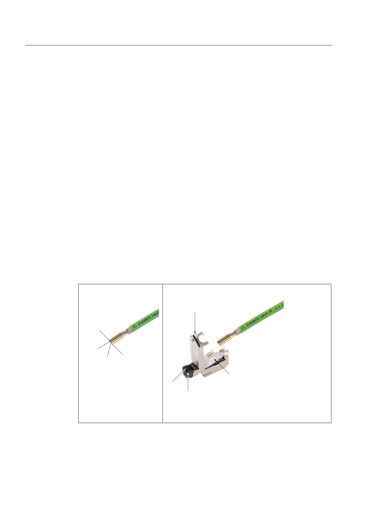
Contacting of the FC cable versions is simple and reliable with the 4 integrated insulation
displacement contacts.
● When the plug case is open, color markings on the contact cover make it easier to
connect the cores to the insulation piercing connecting devices. The user can check that
contact has been made correctly through the transparent plastic material of the contact
cover.
● The stripped end of the cable is inserted in the raised insulation displacement terminals
and the terminals are then pressed down to ensure reliable contacting of the conductors.
①
②
&DVH FRYHU
RUDQJH
EOXH
ZKLWH
\HOORZ
&RQWDFW FRYHU
Strip the IE FC Cable 2x2 using
3LQ
a stripping tool and separate out
3LQ
the cores according to the color
coding on the contact cover of
the FC RJ45 plug.
Open the case cover of the FC RJ45 plug and insert the strands
into their respective end positions according to the color coding.
NCU 7x0.2
62
Manual, 02/2011, 6FC5397-0AP20-0BA0
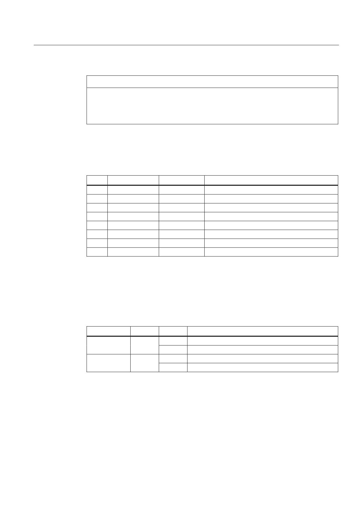
Connecting
7.7 PROFINET
③
④
⑤
&DVH
FRYHU
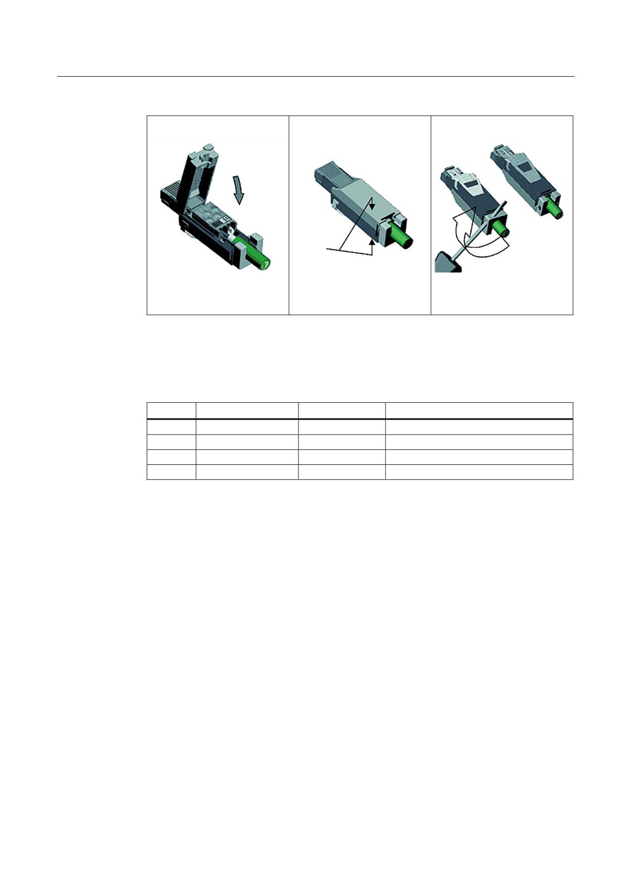
Lower the contact cover so that
Close the case cover and press
Use a screwdriver to turn the
the strands are contacted.
down until it connects with the
snap ring 90°. This will ensure
plug case below.
tension and cable grip.
Assigning the installation cables to the pins on the IE FC RJ45 plug
Between the four individually colored wires of the IE FC RJ45 plug pins, the following
assignments are made:
Pin no.
Wire color
Signal name
Meaning
1
yellow
TX+
Transmit data +
2
Orange
TX-
Transmit data -
3
white
RX+
Receive data +
6
blue
RX-
Receive data -
Additional references
For more information, please refer to:
● The Industry Mall
● The Catalog IK PI
● The manual titled "SIMATIC NET Twisted Pair and Fiber-Optic Networks"
(entry ID: 8763736).
NCU 7x0.2
Manual, 02/2011, 6FC5397-0AP20-0BA0
63
Connecting
7.7 PROFINET
7.7.4
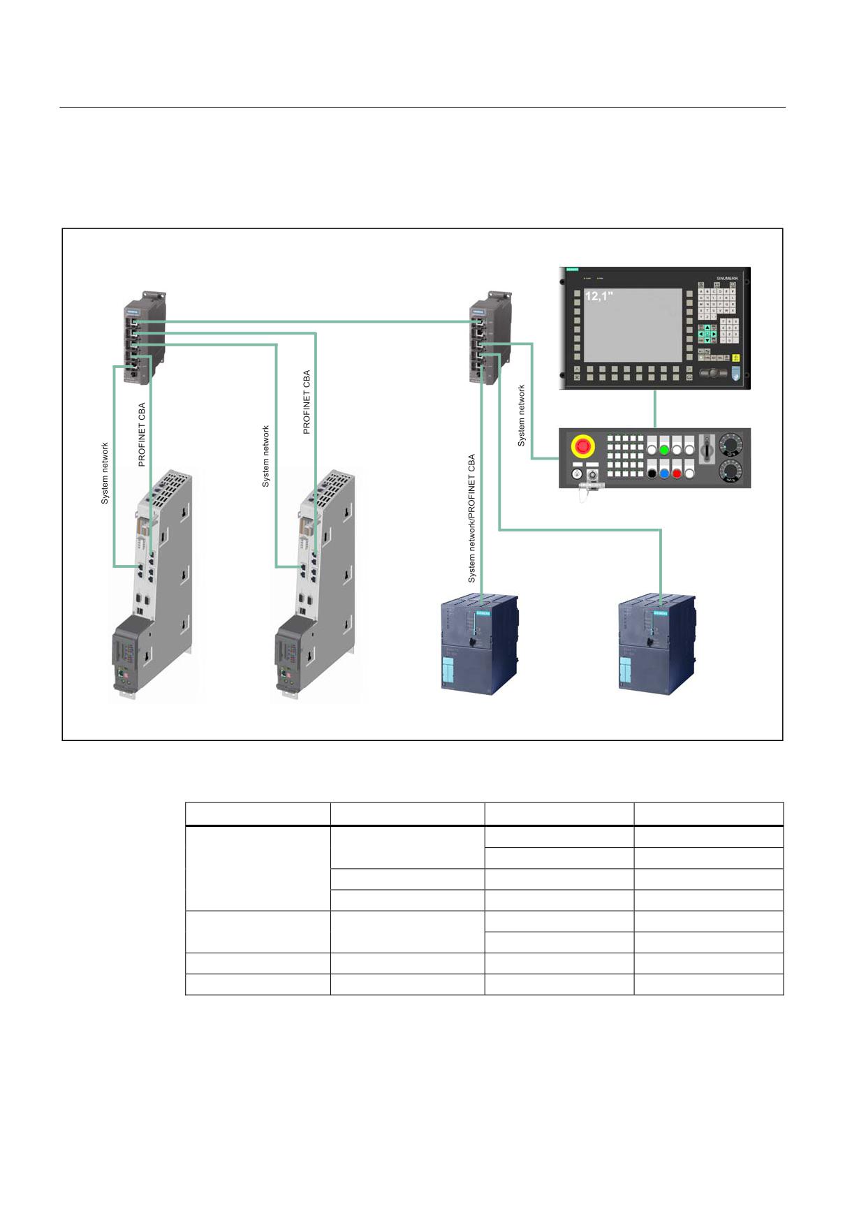
Example PROFINET CBA configuration
The following figure shows a typical system configuration with PROFINET CBA.
3&8
23
6FDODQFH ;
6FDODQFH ;
6\VWHP QHWZRUN 352),1(7 &%$
;
;
1&8
31
1&8
31
;
033
,(
6\VWHP QHWZRUN 352),1(7 &%$
3RUW
3RUW
;
;
&38
31 '3
&38
31 '3
&HQWUDO
8QLW
8QLW
8QLW
Figure 7-10 Example PROFINET CBA configuration
Station name
Module type
Interface
IP address
Central
NCU 730.2 PN
X120
192.168.200.1
Port 1
192.168.200.2
PCU 50.3
X501
192.168.200.5
MPP 483 IE
X20 DHCP server
192.168.200.50
Unit01
NCU 730.2 PN
X120
192.168.200.11
Port 1
192.168.200.12
Unit02
CPU 319-3 PN/DP
PN P1
192.168.200.22
Unit03
CPU 317-2 PN/DP
PN P1
192.168.200.32
NCU 7x0.2
64
Manual, 02/2011, 6FC5397-0AP20-0BA0
Connecting
7.8 PROFIBUS / MPI
7.8
PROFIBUS / MPI
7.8.1
Application
Connectable devices
The following devices can be connected to the PROFIBUS DP interfaces:
● PG/PC
● S7 controllers with PROFIBUS DP interface
● Distributed I/O
● Drive units with PROFIBUS DP interface (standard slaves)
Properties
● Isolated RS 485 interface
● Max. data rate 12 Mbaud
● Supports master/slave operation
● Supports isochronous mode
● PROFIBUS address is set via configuration
● OLPs (6GK1502-1AA00) are not permitted
Note
In addition to the DP (distributed I/O) protocol, X136 can also transmit the MPI (multi
point interface) protocol (software-controlled).
NCU 7x0.2
Manual, 02/2011, 6FC5397-0AP20-0BA0
65
Connecting
7.8 PROFIBUS / MPI
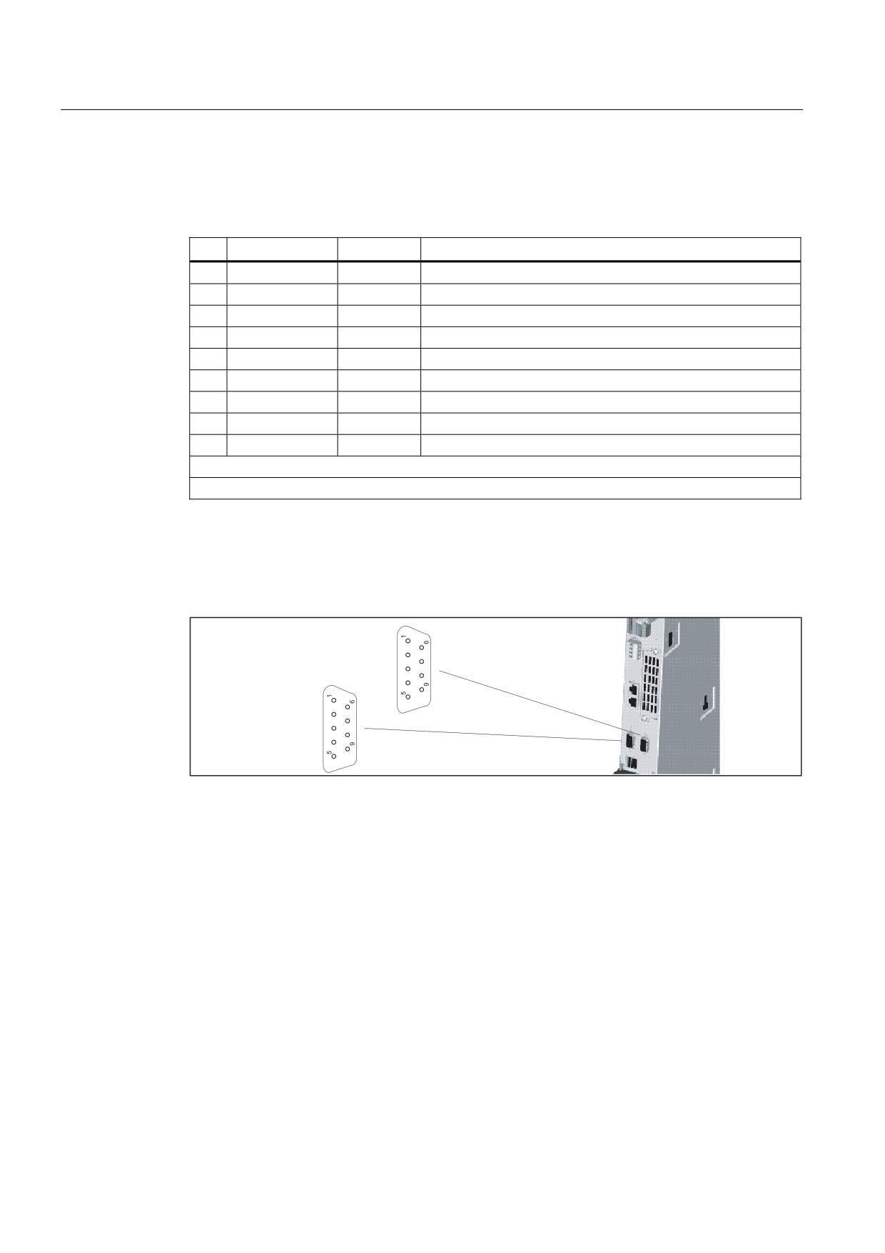
Pin assignment for X126, X136
Table 7- 17 PROFIBUS DP interfaces (X126, X136)
Pin
Signal name
Signal type
Meaning
1
-
-
Reserved, do not use
2
G
VO
Ground to P24_SERV
3
2RS_DP
B
RS-485 differential signal
4
2RTS_DP
O
Request to send
5
1G
VO
Ground to 1P5
6
1P5
VO
5 V power supply for bus terminal, external, short-circuit proof
7
P24_SERV
VO
24 V for teleservice, short-circuit proof, 150mA maximum
8
2XRS_DP
B
RS-485 differential signal
9
-
-
Reserved, do not use
The 1P5 voltage is provided exclusively to supply the bus terminal.
Signal type: VO = Voltage output (power supply) O = Output; B = Bidirectional
Position of connectors
The following figure shows the mounting position and designation of the connectors on the
Control Unit.
'3 03,
;
'3
;
Figure 7-11 PROFIBUS DP/MPI interfaces
NCU 7x0.2
66
Manual, 02/2011, 6FC5397-0AP20-0BA0

Connecting
7.8 PROFIBUS / MPI
7.8.2
PROFIBUS cables and connectors
Cable specifications
The PROFIBUS cable is 2-wire, twisted, and shielded with defined technical data.
Table 7- 18 Cable specifications for X126 and X136
Characteristics
Version
Connector type
9-pin SUB-D socket
Cable type
PROFIBUS cable
Max. cable length
100 m for 12 Mbits
Table 7- 19 Technical data for PROFIBUS cables
Characteristics
Values
Wave impedance
Approximately 135 to 160 Ω (f = 3 to 20 MHz)
Loop resistance
≤ 115 Ω/km
Effective capacitance
30 nF/km
Damping
0.9 dB/100 m (f = 200 kHz)
Permissible conductor cross section
0.3 mm2 to 0.5 mm2
Permissible cable diameter
8 mm + 0.5 mm
Cable lengths and baud rate
The baud rate determines the cable length of a subnet segment.
Table 7- 20 Permitted cable length of a subnet segment for specific baud rates
Baud rate
Max. cable length of a segment (in m)
19.6 to 187.5 kbit/s
10001)
500 kbit/s
400
1.5 Mbit/s
200
3 to 12 Mbit/s
100
1) With isolated interface
Longer cable lengths:
If you must realize greater cable lengths than permitted in one segment, you must use
RS 485 repeaters. The maximum possible cable lengths between two RS 485 repeaters
correspond to the cable length of a segment. You can connect up to 9 RS 485 repeaters in
series.
Note that an RS 485 repeater must be counted as a subnet node when determining the total
number of nodes to be connected. This is true even if the RS 485 repeater is not assigned its
own PROFIBUS address.
NCU 7x0.2
Manual, 02/2011, 6FC5397-0AP20-0BA0
67
Connecting
7.8 PROFIBUS / MPI
Connector features
The bus connector is used to connect the PROFIBUS cables to the PROFIBUS DP
interfaces (X126, X136), thus establishing a connection to additional nodes.
Only bus connectors with a 35° cable outlet should be used in order to ensure that the front
cover can be closed.
7.8.3
Connection components in PROFIBUS
Connection components
Individual nodes are connected by means of bus connectors and PROFIBUS cables.
Remember to provide a bus connector with a programming port at either end of the subnet.
This will give you the option of expanding the subnet if required, for example, for a
programming device.
Use RS 485 repeaters to connect segments or extend cable lengths.
Segments
A segment is a bus line between two terminating resistors. A segment may contain up to 32
nodes. In addition, a segment is limited by the permissible cable length, which varies
according to the transmission rate.
Terminating resistor
A cable must be terminated with its own surge impedance to prevent line disturbances
caused by reflections. Activate the terminating resistor at the first and last node on a subnet
or segment. The control unit must be either the first or the last node on the subnet.
Make sure that the stations to which the terminating resistor is connected are always
supplied with voltage during power-up and operation.
7.8.4
Rules for the laying of PROFIBUS cables
Laying of bus cables
During laying of the PROFIBUS cable, you must avoid:
● twisting
● stretching and
● squeezing
NCU 7x0.2
68
Manual, 02/2011, 6FC5397-0AP20-0BA0

Connecting
7.8 PROFIBUS / MPI
Supplementary conditions
During laying of the indoor bus cable, you must also consider the following supplementary
conditions (dO = outer diameter of the cable):
Table 7- 21 Supplementary conditions for the laying of PROFIBUS cables
Features
Supplementary conditions
Bending radius for a single bend
80 mm (10xdO)
Bending radius (multiple times)
160 mm (20xdO)
Permissible temperature range for cable routing
-5 °C to +50°C
Temperature range for storage and stationary operation
-30°C to +65°C
Additional references
For length codes of prefabricated cables and additional information on PROFIBUS cables,
refer to "Electrical networks" in the PROFIBUS section of the IK PI catalog titled "Industrial
Communication and Field Devices".
7.8.5
Connecting PROFIBUS DP
Introduction
PROFIBUS cables are connected to the X126/X136 interface by means of a bus connector.
Wiring the bus connector
1. Proceed as follows to connect the bus connector:
2. Plug the bus connector into the corresponding interface on the control unit.
3. Screw the bus connector into place.
As the control unit is located at the start or end of a segment, you must switch on the
terminating resistor ("ON" switch setting).
7HUPLQDWLQJ UHVLVWRU
RQ
7HUPLQDWLQJ UHVLVWRU
RQ
VZLWFKHG RQ
VZLWFKHG RII
RII
RII
Figure 7-12 Terminating resistor switched on and off
Note
Make sure that the stations on which the terminating resistor is located are always
supplied with voltage during booting and operation.
NCU 7x0.2
Manual, 02/2011, 6FC5397-0AP20-0BA0
69
Connecting
7.8 PROFIBUS / MPI
7.8.6
Disconnecting stations from the PROFIBUS
Removing the bus connector
You can remove the bus connector with a looped-through bus cable from the PROFIBUS DP
interface at any time without interrupting data traffic on the bus.
CAUTION
Data exchange on the bus can be interrupted!
A bus segment must always be terminated with the terminating resistor at both ends. This
is not the case, for example, if the last node with a bus connector is de-energized. Because
the bus connector takes its voltage from the node, this terminating resistor is ineffective.
Make sure that the nodes at which the terminating resistor is connected are always
energized.
7.8.7
Operating the X136 interface as MPI
Applications
The X136 interface can also be operated as an MPI interface instead of a PROFIBUS DP
interface. The typical (default) baud rate is 187.5 Kbaud. A baud rate of up to 12 MBaud can
be set for communication with other CPUs. It should be noted, however, that a rate of
12 MBaud is not supported by all CPUs (e.g. smaller SIMATIC S7 CPUs).
The following list provides examples of when using MPI (multi-point interface) may prove
effective:
● If a PC/PG with an MPI is being used
● If an MPI-type handheld unit is being used
Operate MPI like PROFIBUS
The information on wiring the connector (terminating resistors) for PROFIBUS and the rules
on the laying of cables for PROFIBUS apply to this interface as well. When carrying out this
procedure, consult the relevant references.
Connector features
The bus connector is used to connect the MPI bus cable to the MPI (X136). This enables
you to establish connections to additional nodes (e.g. PG or SIMATIC S7-CPU). Only bus
connectors with a 35° cable outlet should be used in order to ensure that the front cover can
be closed.
NCU 7x0.2
70
Manual, 02/2011, 6FC5397-0AP20-0BA0
Connecting
7.9 Digital inputs/outputs
MPI bus cable
The PROFIBUS cable specifications apply here as well. Please note the relevant information
on setting up an MPI network.
Setting up an MPI network
Keep in mind the following basic rules when setting up an MPI network:
● When using the interface as an MPI interface, it is not possible to arrange additional
control for a drive in isochronous mode or to connect distributed I/Os to this interface.
● An MPI bus line must be terminated at both ends. This is achieved by activating the
terminating resistor in the MPI connector in the first and last station and deactivating the
other terminating resistors.
● At least one terminator must be supplied with 5 V.
This means that an MPI connector with an activated terminating resistor must be
connected to a device that is switched on.
● Spur lines (cables leading from the bus segment to the node) should be as short as
possible, i.e. < 5 m in length. Unused spur lines should be removed wherever possible.
● Every MPI station must be connected to the bus first and then activated.
To disconnect the station, it must first be deactivated. Then, the station can be removed
from the bus.
● Maximum cable lengths:
-
200 m per bus segment
–
2000 m total length with RS 485 repeaters
7.9
Digital inputs/outputs
7.9.1
DIO application
Connecting sensors and actuators
Digital inputs and outputs can be used to connect various sensors and actuators to the two
12-pin connectors (X122 and X132) on the front panel.
The following types of digital I/O are used:
● Digital inputs
● Bidirectional digital inputs/outputs
The assignment of I/Os to functions can be parameterized freely by the user. Special
functions, such as probe inputs (rapid inputs only) and cam outputs, can also be assigned to
the inputs/outputs.
NCU 7x0.2
Manual, 02/2011, 6FC5397-0AP20-0BA0
71

Connecting
7.9 Digital inputs/outputs
The enables for the drive units and/or motors (Line Module, Motor Module) connected to the
control unit can be switched using the digital inputs.
Note
Terminal assignments
When commissioning the drive wizard, the digital inputs/outputs are correspondingly
preassigned functions.
For more information about terminal assignment, see:
System Manual "Machine Configuration Guidelines", Chapter "Commmunications in the
System", 10/2009 Edition.
Commissioning Manual "IBN CNC: NCK, PLC, Drive", Chapter "Tips", 03/2010 Edition.
Access to digital inputs/outputs
Note
The digital inputs/outputs are updated in accordance with the set PROFIBUS bus clock pulse
for SINAMICS Integrated.
Pin assignment
Table 7- 22 X122 digital inputs/outputs
Pin
Signal name
Signal type
Meaning
1
DI0
I
Digital input 0
2
DI1
I
Digital input 1
3
DI2
I
Digital input 2
4
DI3
I
Digital input 3
5
G1
GND
Ground for DI0 - DI3 (functionally-separated relative
to G)
6
G
GND
Ground
7
DI/DO8
B
Digital input/output 8
8
DI/DO9
B
Digital input/output 9 (rapid input)
9
G
GND
Ground
10
DI/DO10
B
Digital input/output 10 (rapid input)
11
DI/DO11
B
Digital input/output 11 (rapid input)
12
G
GND
Ground
Signal type: B = Bidirectional; I = Input; GND = Reference potential (ground)
NCU 7x0.2
72
Manual, 02/2011, 6FC5397-0AP20-0BA0
Connecting
7.9 Digital inputs/outputs
Table 7- 23 X132 digital inputs/outputs
Pin
Signal name
Signal type
Meaning
1
DI4
I
Digital input 4
2
DI5
I
Digital input 5
3
DI6
I
Digital input 6
4
DI7
I
Digital input 7
5
G2
GND
Ground for DI4 - DI7 (functionally-separated relative
to G)
6
G
GND
Ground
7
DI/DO12
B
Digital input/output 12
8
DI/DO13
B
Digital input/output 13 (rapid input)
9
G
GND
Ground
10
DI/DO14
B
Digital input/output 14 (rapid input)
11
DI/DO15
B
Digital input/output 15 (rapid input)
12
G
GND
Ground
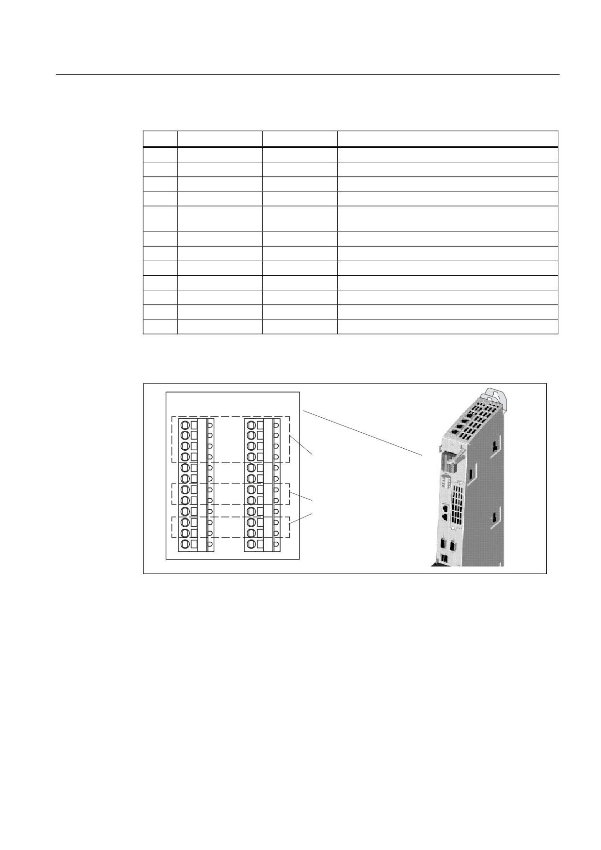
Position of connectors
;
;
'LJLWDO LQSXWV
3LQV
'LJLWDO LQSXWV RXWSXWV
3LQV
DQG
Figure 7-13 Digital inputs and digital inputs/outputs (interfaces X122 and X132)
NCU 7x0.2
Manual, 02/2011, 6FC5397-0AP20-0BA0
73
Connecting
7.9 Digital inputs/outputs
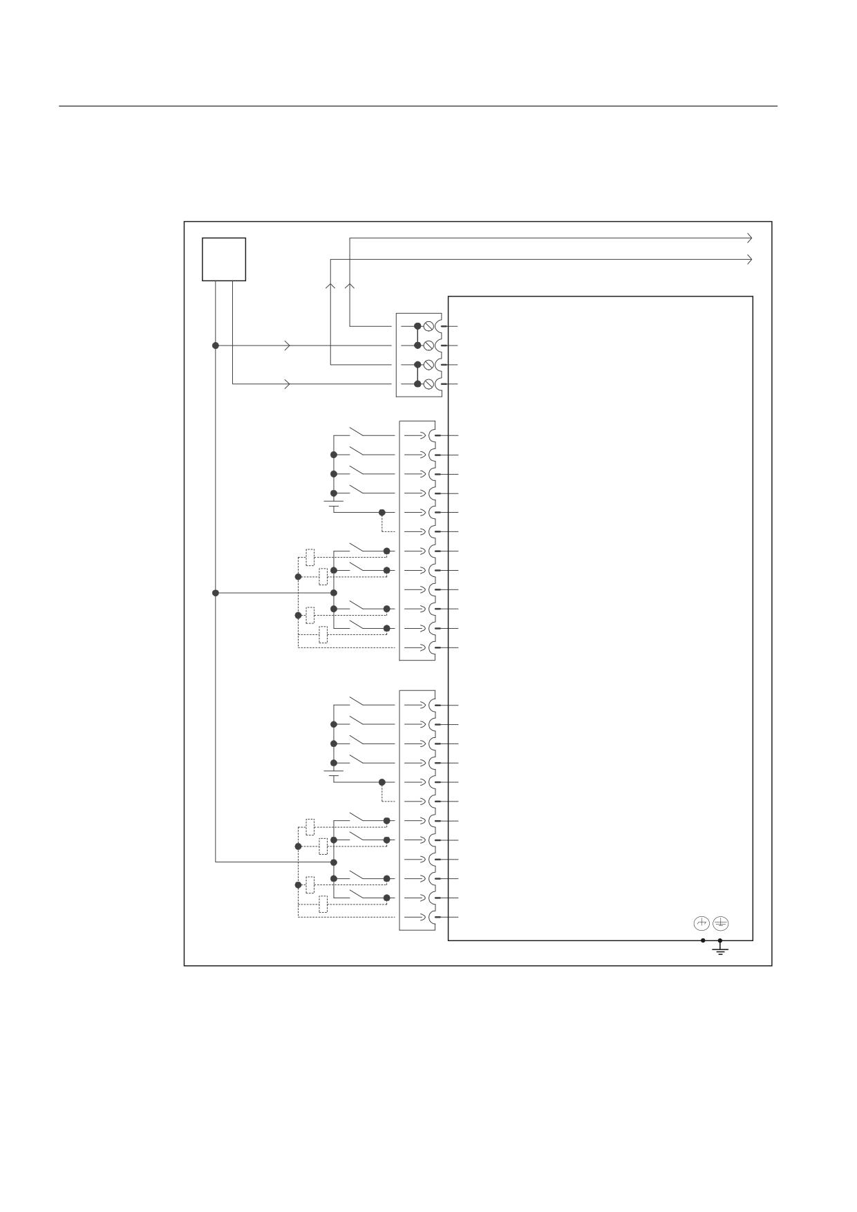
Block diagram
The following figure shows the block diagram for the digital inputs/outputs of a control unit.
H[W
0
9
0
;
9
0
0
0
0
;
',
',
',
',
0
1XPHULFDO &RQWURO 8QLW
1&8
0
', '2
', '2
+LJK VSHHG LQSXWV RXWSXWV
0
PXVW EH VKLHOGHG
', '2
-XPSHU RSHQ HOHFWULFDO LVRODWLRQ
', '2
IRU GLJLWDO LQSXWV ',
0
&DQ EH SDUDPHWHUL]HG DV
;
LQSXW RXWSXW
',
',
',
',
0
0
', '2
', '2
0
', '2
', '2
0
Figure 7-14 Block diagram for digital inputs/outputs
NCU 7x0.2
74
Manual, 02/2011, 6FC5397-0AP20-0BA0

Connecting
7.9 Digital inputs/outputs
7.9.2
Connecting digital inputs/outputs
Cable specification
Table 7- 24 Cable specification for X122 and X132
Characteristics
Version
Connector type
Screw-type terminals
Connection option
Up to 0.5 mm2
Current carrying capacity
4 A max.
Connecting cables for digital inputs/outputs
The following conditions apply to connecting cables:
● Use flexible cables with a cable cross-section of at least 0.25 mm2
● Ferrules are not required.
Note
To achieve optimum interference suppression, shielded cables must be used to connect
measuring inputs or BEROs.
Tools required
3.5-mm screwdriver or power screwdriver
Wiring digital inputs/outputs
1. Strip 6 mm of insulation from the wires.
2. Wire the digital inputs of the interface for connection of the sensors.
3. Wire the digital outputs of the interface for connection of the actuators.
4. Insert the cable into the corresponding spring-loaded terminal.
Using shielded cables
The following options are available for the shield connection when using shielded cables:
1. Attach the cable shield to a grounded shielding bus immediately after the cable entry
point in the cabinet (strip the insulation off the cable for this purpose).
2. Continue routing the shielded cable as far as the module but do not make a connection to
the shield there.
NCU 7x0.2
Manual, 02/2011, 6FC5397-0AP20-0BA0
75
Connecting
7.9 Digital inputs/outputs
Using a shield connection
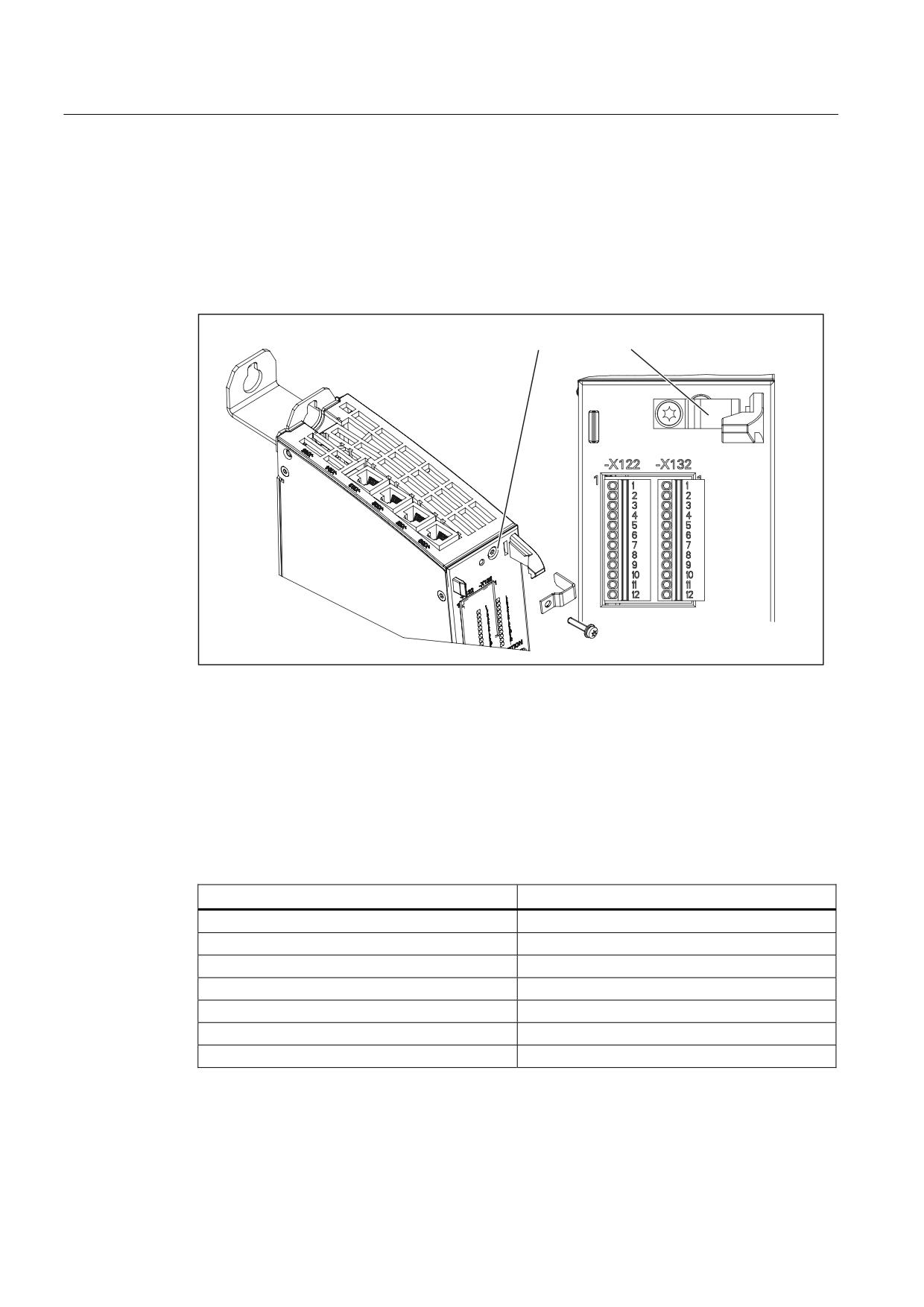
1. Remove the fixing bracket.
2. Insert the cable and fasten the fixing bracket.
This figure shows where to attach the cables to the front panel connector and where to apply
the cable interference suppression using the shield connecting element.
6KLHOG VXSSRUW
Figure 7-15 Using a shield connection
7.9.3
Technical data
Digital inputs on X122/X132
Table 7- 25 Technical data of digital inputs X122/X132
Parameters
Values
Voltage
-3 V to 30 V
Typical power consumption
10 mA at 24 V DC
Galvanic isolation
Reference potential is terminal G1 or G2
Signal level (including ripple)
High signal level: 15 V to 30 V
Low signal level: -3 V to 5 V
Signal propagation delays
L → H: 50 μs
H → L: 100 μs
NCU 7x0.2
76
Manual, 02/2011, 6FC5397-0AP20-0BA0

Connecting
7.9 Digital inputs/outputs
Digital inputs/outputs on X122/X132
Table 7- 26 Technical data of the digital inputs/outputs of X122/X132
Parameters
Values
As an input
Voltage
-3 V to 30 V
Typical power consumption
10 mA at 24 V DC
Signal level (including ripple)
High signal level: 15 V to 30 V
Low signal level: -3 V to 5 V
Pins 8, 10 and 11 are "rapid inputs"
Signal propagation delays of inputs/"rapid inputs"
L → H: 50 μs/5 μs
H → L: 100 μs/50 μs
As an output
Voltage
24 V DC
Maximum load current per output
500 mA
Note
An open input is interpreted as "low".
Only "rapid inputs" can be used as inputs for BEROs and probes.
Terminals G1 or G2 must be connected for the digital inputs to work. This can be done as
follows:
Connect the coupled-motion ground reference of the digital inputs, or provide a jumper to
terminal G. (Notice! This removes the galvanic isolation for these digital inputs.)
NCU 7x0.2
Manual, 02/2011, 6FC5397-0AP20-0BA0
77

Connecting
7.10 USB
7.10
USB
The USB interfaces are used exclusively for service purposes, correspond to the norm and
are, therefore, not described in detail here.
Table 7- 27 Cable specification for X125 and X135
Characteristics
Versions
Connector type
Double USB socket - type A
Version
USB 2.0
Current carrying capacity
0.5 A per channel
Max. cable length
5 m
Note
The 5 V power supply is designed to be short-circuit proof.
86% LQWHUIDFHV
Figure 7-16 Position of USB interfaces
NCU 7x0.2
78
Manual, 02/2011, 6FC5397-0AP20-0BA0
Connecting
7.11 Measuring sockets
7.11
Measuring sockets
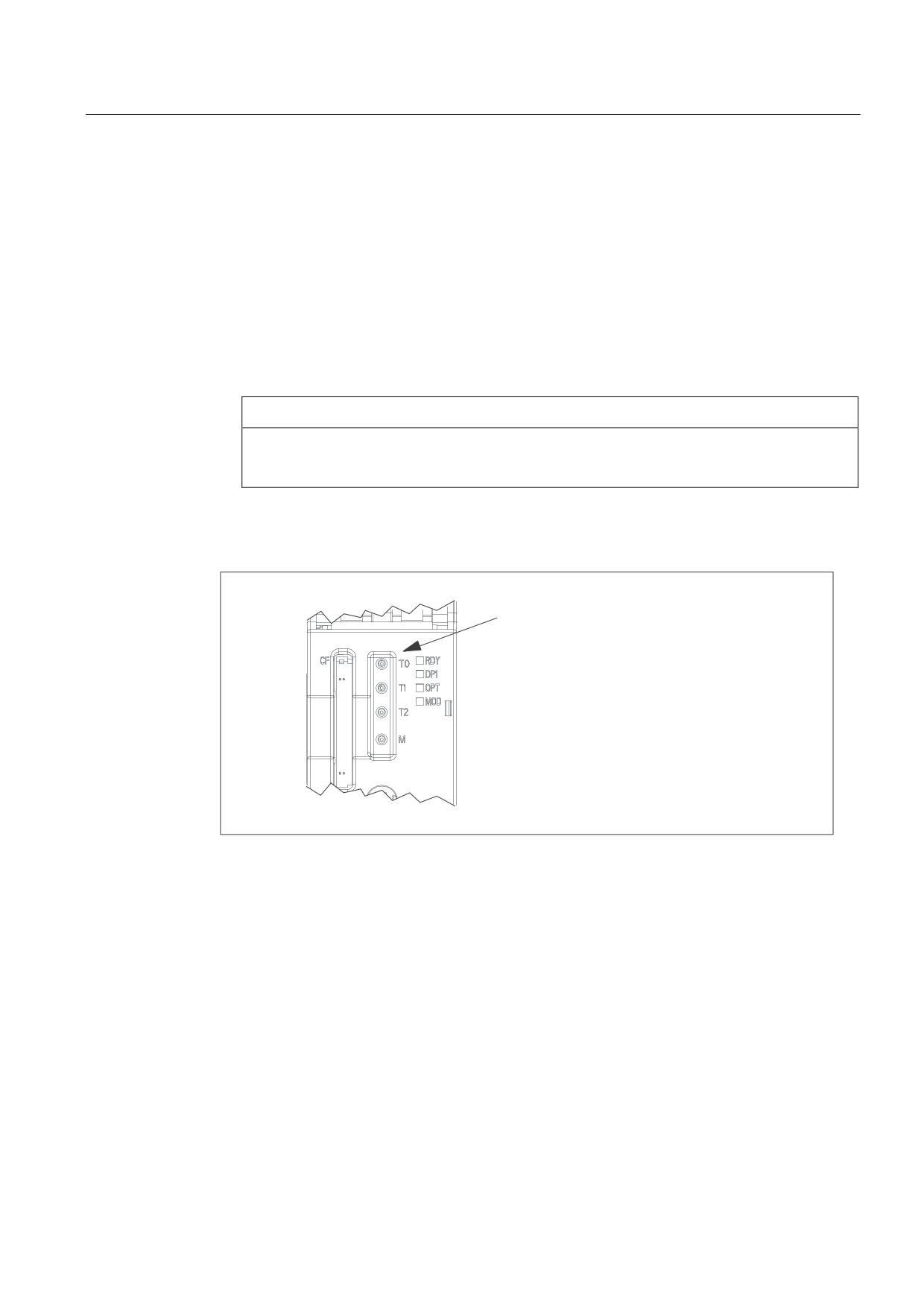
Application
The test sockets are used to output analog signals. Any interconnectable signal can be
output to any test socket on the control unit.
● Max. output range of the test signal: 0 ... 5 V
● Test sockets have to be parameterized before use, as there is no default setting on
delivery.
CAUTION
The test sockets should be used exclusively for servicing purposes.
The measurements may only be carried out by appropriately trained specialists.
Test socket position
7HVW VRFNHWV PP
7
7HVW
VRFNHW
7
7HVW
VRFNHW
7
7HVW
VRFNHW
0
5HIHUHQFH
Figure 7-17 Test socket arrangement
NCU 7x0.2
Manual, 02/2011, 6FC5397-0AP20-0BA0
79
Connecting
7.11 Measuring sockets
NCU 7x0.2
80
Manual, 02/2011, 6FC5397-0AP20-0BA0

Technical Data
8
Table 8- 1
Safety-related data
Protection class
I (protective conductor) as per EN 61800-5-1
Degree of protection to EN 60529
IP20 or IPXXB with option slot cover
or option module inserted
Certifications
CE, cULus
Pollution degree
2
Cooling
Open-circuit-ventilated
Mounting position
Vertical
Table 8- 2
Electrical and mechanical data (1)
NCU 710.2
NCU 720.2
NCU 720.2 PN
Main memory
1 GB DRAM
1 GB DRAM
1 GB DRAM
1 MB SRAM
1 MB SRAM
1 MB SRAM
SIMATIC S7 - integrated
PLC 317-2 DP
PLC 317-2 DP
PLC 319-3 PN/DP
Input voltage
24 V DC
24 V DC
24 V DC
Power consumption, max.
170 W
174 W
216 W
Power loss
22 W
25 W
55 W
Dimensions (WxHxD)
50 x 455 x 272 mm
50 x 455 x 272 mm
50 x 455 x 272 mm
Weight, approx.
2.9 kg
2.9 kg
3.8 kg
Table 8- 3
Electrical and mechanical data (2)
NCU 730..2
NCU 730.2 PN
Main memory
1 GB DRAM
1 GB DRAM
1 MB SRAM
1 MB SRAM
SIMATIC S7 - integrated
PLC 317-2 DP
PLC 319-3 PN/DP
Input voltage
24 V DC
24 V DC
Power consumption, max.
216 W
225 W
Power loss
55 W
65 W
Dimensions (WxHxD)
50 x 455 x 272 mm
50 x 455 x 272 mm
Weight, approx.
3.6 kg
3.8 kg
NCU 7x0.2
Manual, 02/2011, 6FC5397-0AP20-0BA0
81
Technical Data
NCU 7x0.2
82
Manual, 02/2011, 6FC5397-0AP20-0BA0
Connectable components
9
9.1
NX10/15
9.1.1
Description
Properties
Using this module, you can expand the performance of an axis grouping of the
SINUMERIK 840D sl CNC automation system. Each NX10 can control up to 3 additional
axes and each NX15 can control up to 6 additional axes.
The NX10/15 has the following interfaces:
●
4 DRIVE-CLiQ (X100 - X103)
●
4 digital inputs and 4 digital inputs/outputs (X122)
● Power supply (X124)
NCU 7x0.2
Manual, 02/2011, 6FC5397-0AP20-0BA0
83
Connectable components
9.1 NX10/15
Display
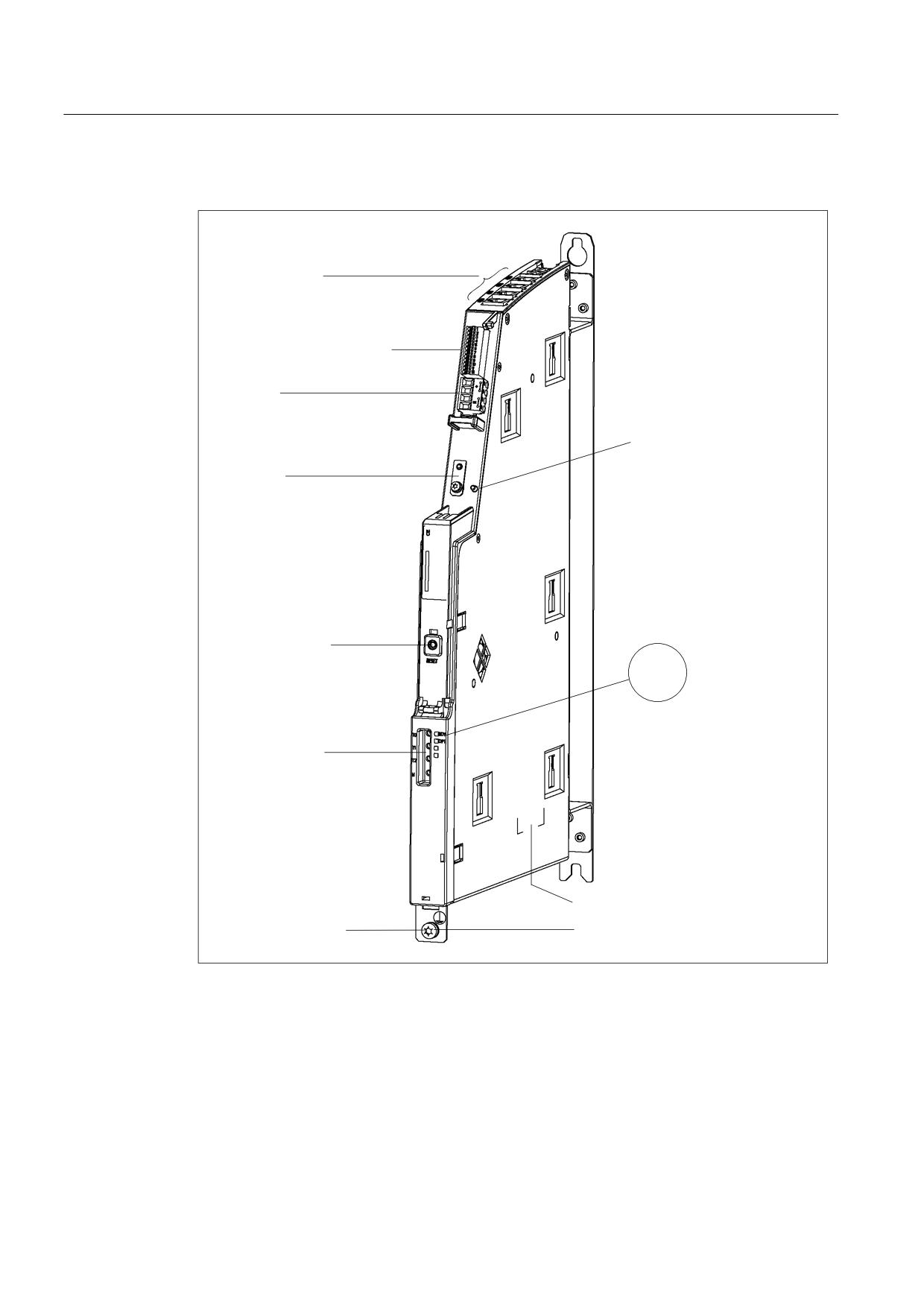
;
;
'5,9( &/L4 LQWHUIDFHV
;
'LJLWDO LQSXWV RXWSXWV
;
(OHFWURQLF SRZHU VXSSO\
3LQ
%UDFNHW
/('V
5(6(7 EXWWRQ
ჱ 5'<
ჱ
'3
7
7
0HDVXULQJ
VRFNHWV
7\SH SODWH
&RQQHFWLRQ WR JURXQG
3URWHFWLYH FRQGXFWRU FRQQHFWLRQ
0
1P
0
1P
Figure 9-1
Representation of NX10/15 (without cover)
Type plate
The NX10/15 module type plate contains basically the same information as the control unit
type plate (see Section 4.4).
NCU 7x0.2
84
Manual, 02/2011, 6FC5397-0AP20-0BA0
Connectable components
9.1 NX10/15
LED displays
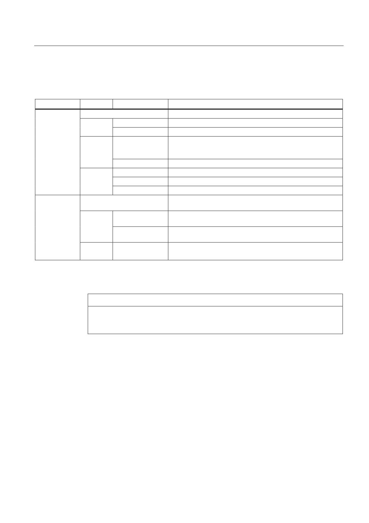
Table 9- 1
Description of LEDs on the NX10/15
LED
Color
Status
Description
Off
Electronic power supply outside permissible tolerance range
Continuous light
NX10/15 is ready for operation
RDY,
Green
Flashing 2 Hz
Writing to CompactFlash Card
READY
H1
Continuous light
At least one fault is pending (e.g., RESET, watchdog monitoring,
Red
basic system fault).
NX10/15 is booting up.
Flashing 0.5 Hz
Boot error (e.g. firmware cannot be loaded into the RAM)
Orange
Continuous light
Firmware loading into RAM
Flashing 0.5 Hz
Unable to load firmware into RAM
Flashing 2 Hz
Firmware CRC fault
Off
Electronic power supply outside the permissible tolerance range,
NX10/15 is not ready for operation.
DP1,
Green
Continuous light
CU_LINK is ready for communication and cyclic communication is
CU_LINK
running
H2
Flashing 0.5 Hz
CU_LINK is ready for communication and no cyclic communication is
running
Red
Continuous light
At least one CU_LINK fault is present.
CU_LINK not ready for operation (e.g., after POWER ON)
RESET button
The RESET button is on the front of the module under the cover.
NOTICE
When the pushbutton is actuated, the locally connected drive systems are brought to a
standstill with no feedback to the control. In other words, the drive and controller run
asynchronously once the drive has successfully booted up.
NCU 7x0.2
Manual, 02/2011, 6FC5397-0AP20-0BA0
85
Connectable components
9.1 NX10/15
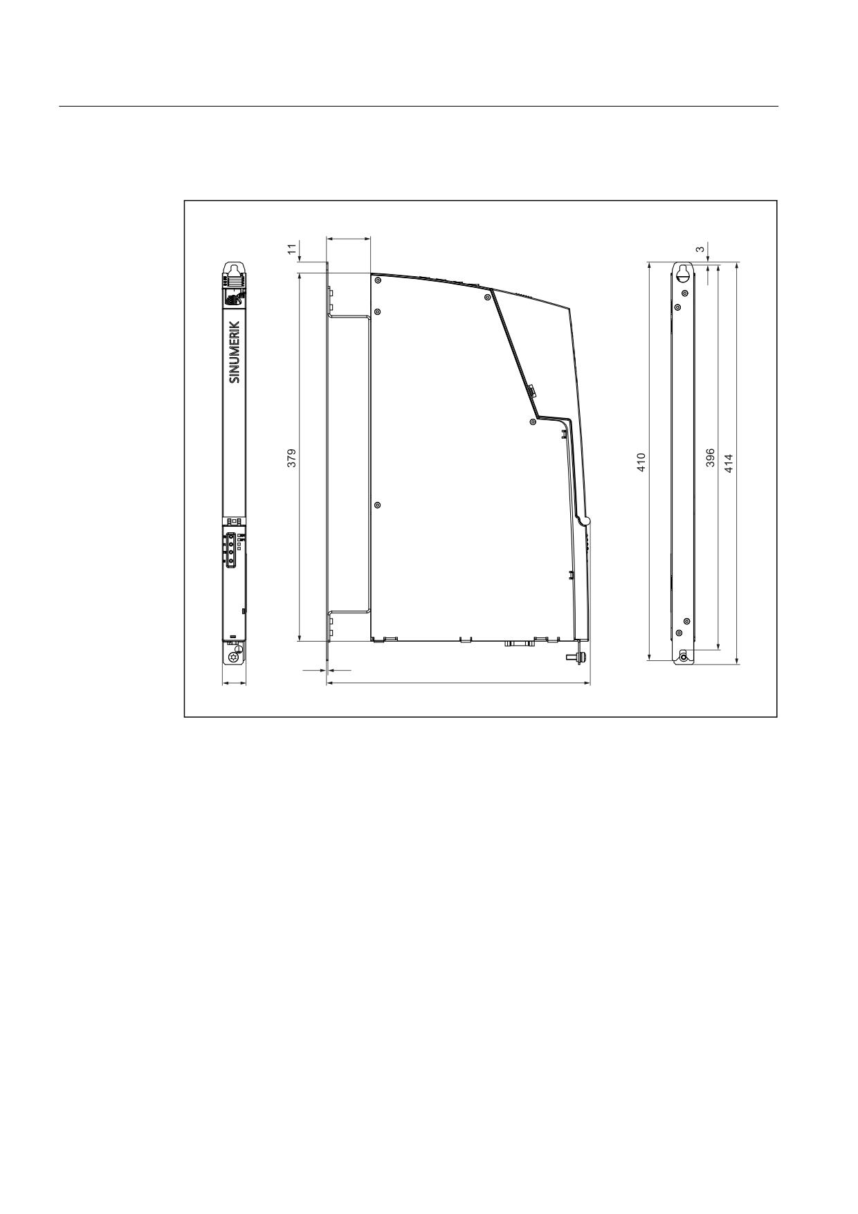
9.1.2
Dimension drawing
Figure 9-2
NX10/15 dimension drawing (dimensions in mm)
NCU 7x0.2
86
Manual, 02/2011, 6FC5397-0AP20-0BA0
Connectable components
9.1 NX10/15
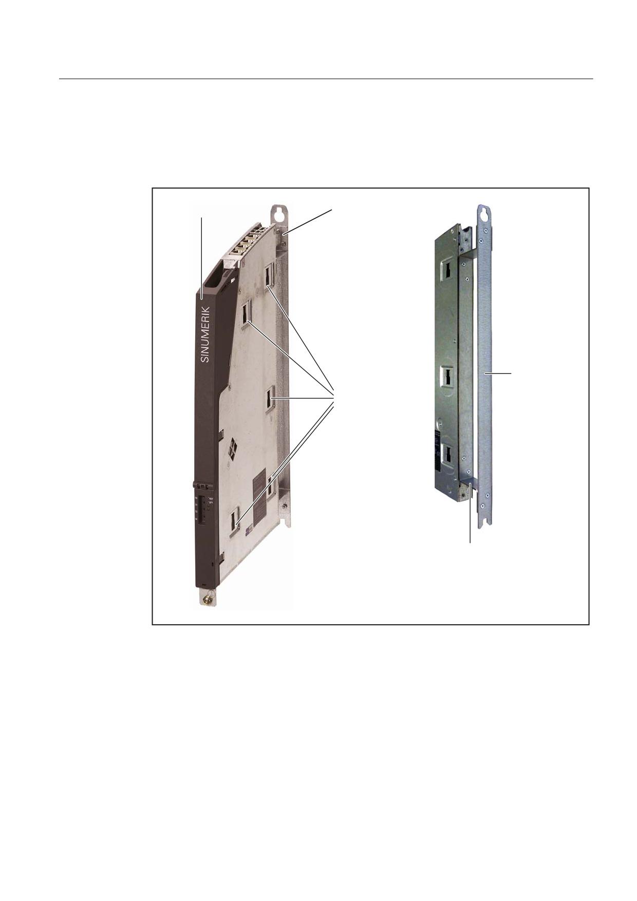
9.1.3
Mounting
Mounting aids
&RYHU
6SDFHU
+ROGLQJ SODWH
&XWRXWV IRU
ODWHUDO PRXQWLQJ
$QJOH SODWH
Figure 9-3
NX10/15 mounting aids
NCU 7x0.2
Manual, 02/2011, 6FC5397-0AP20-0BA0
87
Connectable components
9.1 NX10/15
Designs
Basically, the NX10/15 is integrated exactly the same way as the control unit into the
SINAMICS drive line-up in:
● Lateral mounting of NX 10/15 on the SINAMICS drive line-up (see also Manual control
units Supplementary System Components, Chapter 2.4 "Installation").
First, you must insert the supports into the cutouts of the NX that are attached to the line
module. Then the NX can be hooked in on the line module.
● NX10/15 with spacer directly on the rear wall of the control cabinet - standard.
The NX is secured with two M6 screws (6 Nm) to the mounting area.
Mounting an NX10/15 without spacers
In addition, you can secure the NX10/15 directly on the rear wall of the control cabinet even
without spacers. Using this method, you must dismantle the spacer attached as standard in
the delivery state.
Note
The spacer is secured with M3 torx screws on the NX. The screws must be screwed in with a
T10 screwdriver at a tightening torque of 0.8 Nm.
1. Remove mounting plate.
2. Remove angle plate.
3. Secure mounting plate on the NX.
4. Secure NX with two M6 screws (6 Nm) on the mounting surface.
CAUTION
The 80 mm ventilation spaces above and below the components must be observed.
NCU 7x0.2
88
Manual, 02/2011, 6FC5397-0AP20-0BA0
Connectable components
9.1 NX10/15
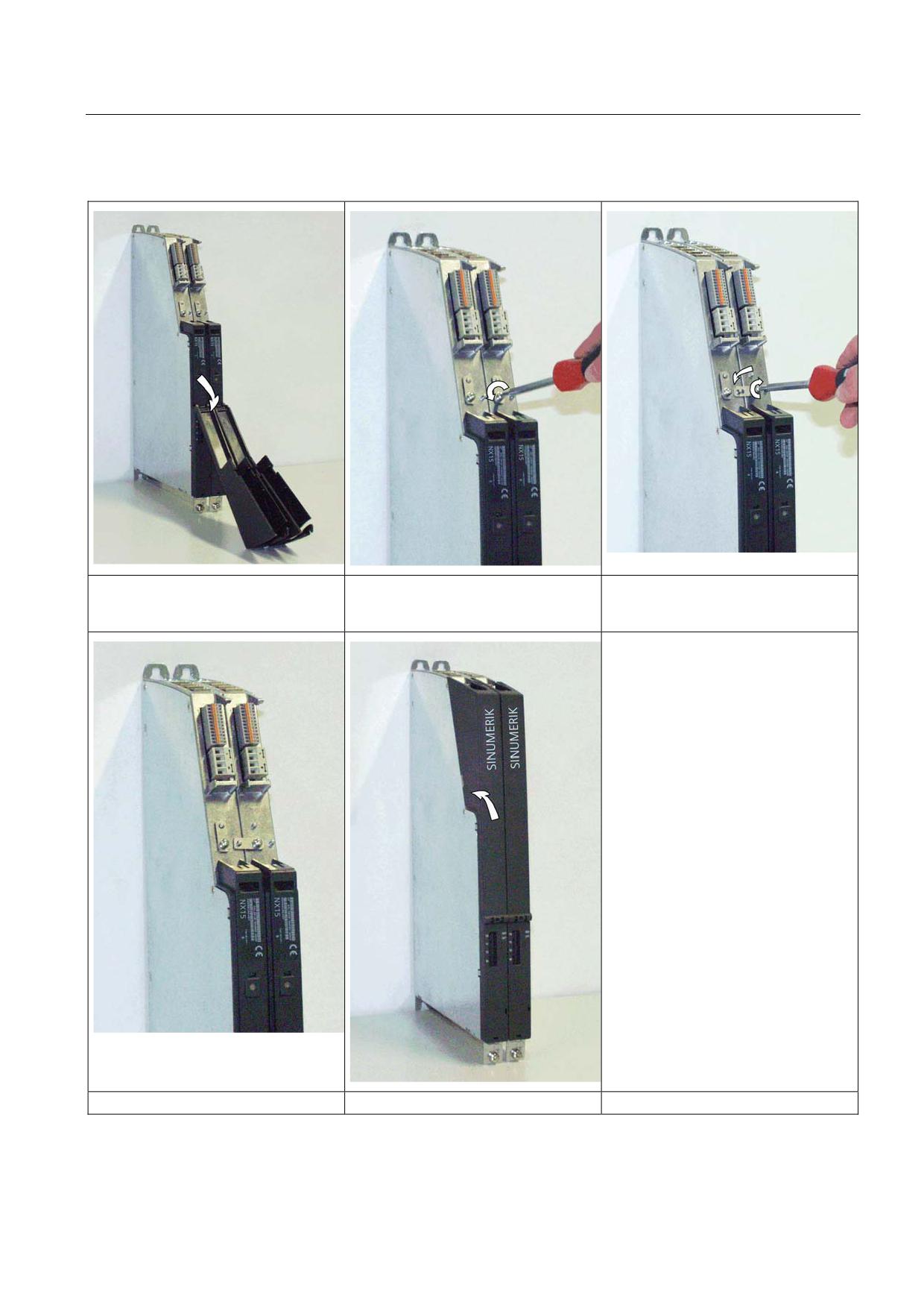
Table 9- 2
Mounting an NX10/15 on another NX10/15
Opening the cover.
Unscrewing the screw.
The bracket must be moved so that the
pin is in the opening of the bracket.
Tighten the screw.
Mounted bracket.
Closing the cover.
NCU 7x0.2
Manual, 02/2011, 6FC5397-0AP20-0BA0
89
Connectable components
9.1 NX10/15
9.1.4
Connection
Power supply X124
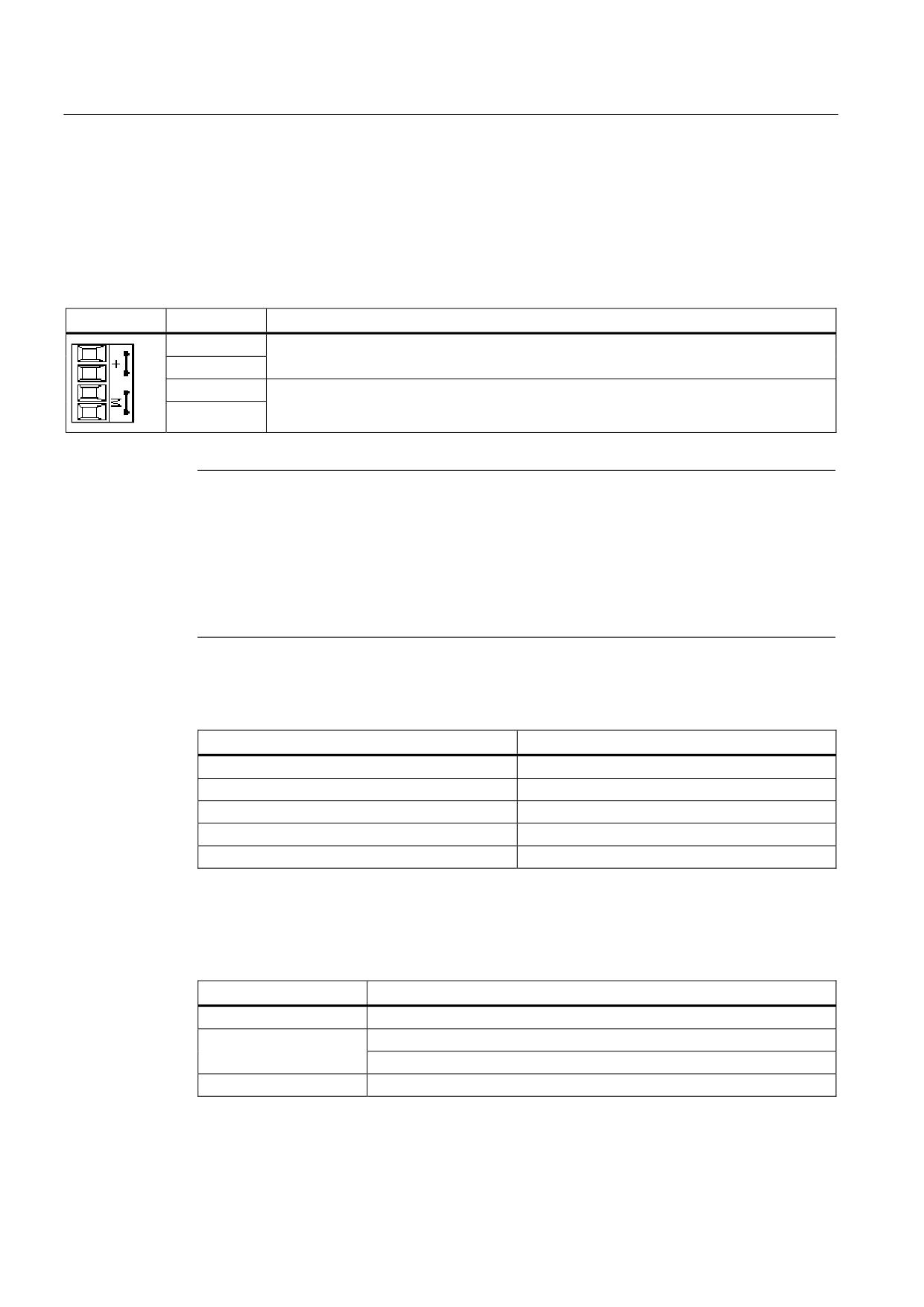
Table 9- 3
Pin assignment for X124
Terminal
Function
+
24 V DC power supply (20.4 V - 28.8 V)
+
G
Ground
G
Note
The two "+" and "G" terminals are jumpered in the connector and not in the device. This
ensures that the supply voltage is looped through.
The current consumption increases by the current consumption of DRIVE-CLiQ and the
digital outputs.
When using external power supplies (e.g. SITOP), the ground potential must be connected
with the protective ground terminal (PELV).
Table 9- 4
Cable specifications for X124
Characteristics
Version
Connector type
Screw-type terminals
Connection option
Up to 2.5 mm2
Max. current carrying capacity incl. loop-through
20 A
Maximum power consumption
0.8 A (without load)
Max. cable length
10 m
DRIVE-CLiQ interfaces X100 - X103
Table 9- 5
Characteristics of X100 - X103
Characteristic
Version
Connector type
DRIVE-CLiQ plug
Cable type
DRIVE-CLiQ standard (inside the control cabinet)
MOTION CONNECT (outside the control cabinet)
Max. cable length
70 m
NCU 7x0.2
90
Manual, 02/2011, 6FC5397-0AP20-0BA0
Connectable components
9.1 NX10/15
Table 9- 6
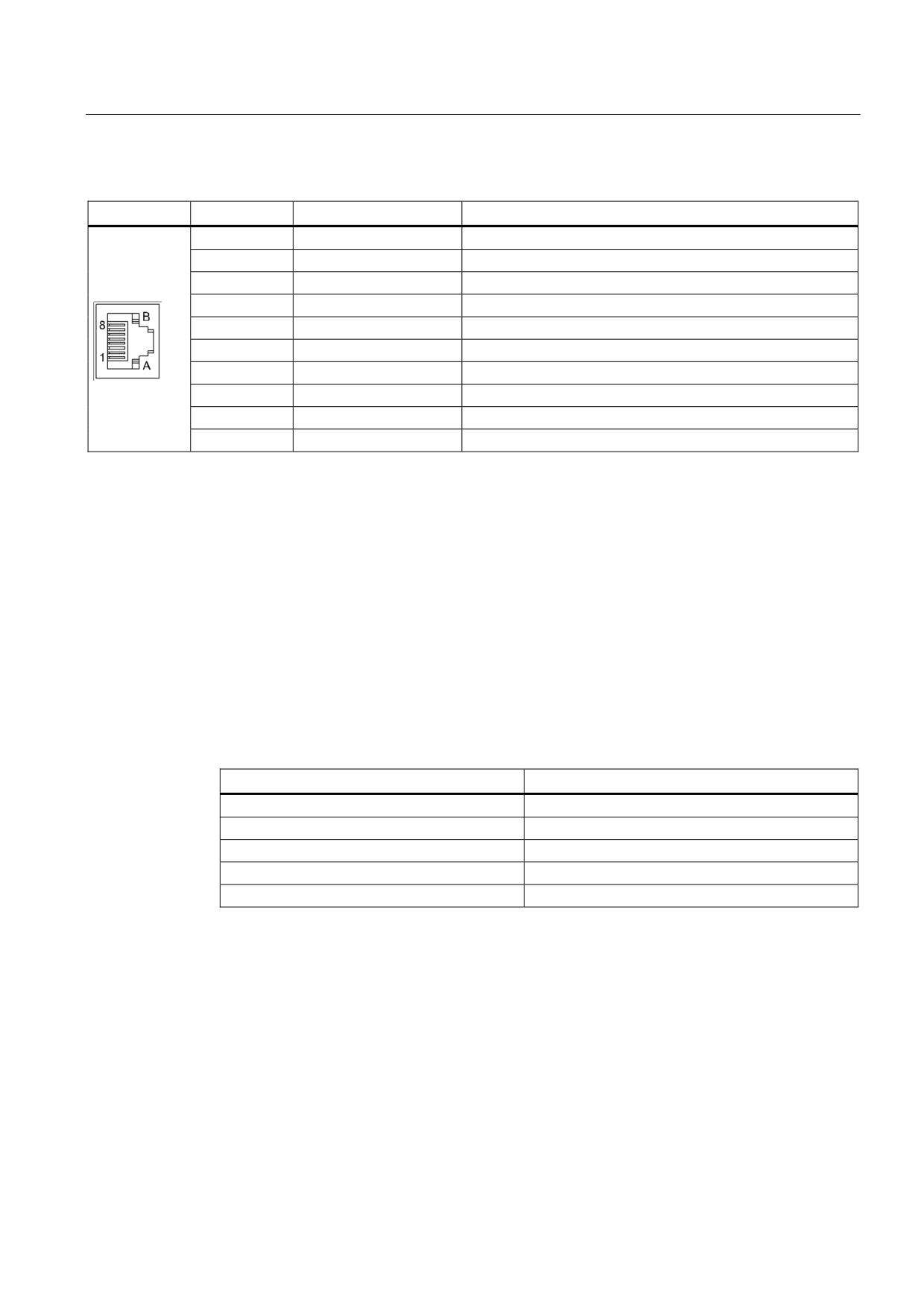
Pin assignment for X100 - X103
Pin
Signal name
Technical specifications
1
TXP
Transmit data +
2
TXN
Transmit data -
3
RXP
Receive data +
4
-
Reserved, do not use
5
-
Reserved, do not use
6
RXN
Receive data -
7
-
Reserved, do not use
8
-
Reserved, do not use
A
+ (24 V)
Power supply
B
G (0 V)
Electronics ground
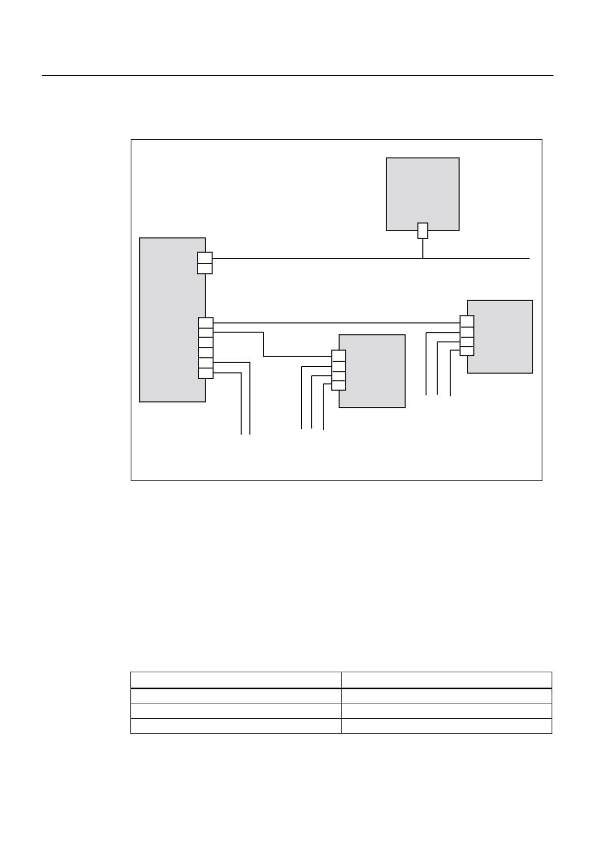
DRIVE-CLiQ topology
NX10/15 components can be connected to the control unit via DRIVE-CLiQ. The following
rules apply to wiring of the NX10/15:
● Only one star topology is permitted between the NX10/15 and the control unit. This
means that only one NX10/15 can be operated per DRIVE-CLiQ port on a control unit.
● DRIVE-CLiQ ports not assigned to NX10/15 can be wired to other DRIVE-CLiQ
components.
● Once an NX10/15 has been connected and configured, you cannot simply insert it into a
different DRIVE-CLiQ port, as the addresses of the integrated drives are set permanently
from the point of view of the PLC. The following table illustrates this relation:
Table 9- 7
NX10/15 PROFIBUS addresses
DRIVE-CLiQ port on the NCU
Drive PROFIBUS addresses
X105
15
X104
14
X103
13
X102
12
X101
11
NCU 7x0.2
Manual, 02/2011, 6FC5397-0AP20-0BA0
91
Connectable components
9.1 NX10/15
The following figure shows a sample topology:
(7
1&8
([WHUQDO 352),%86 '3 '3
;
;
1;
;
;
1;
;
;
'3 $GUHVVH
;
;
'3 DGGUHVV
6XE WRSRORJ\
1;
6XE WRSRORJ\
'5,9( &/L4
1;
FRPSRQHQWV RQ WKH
1&8
Figure 9-4
NX10/15 topology
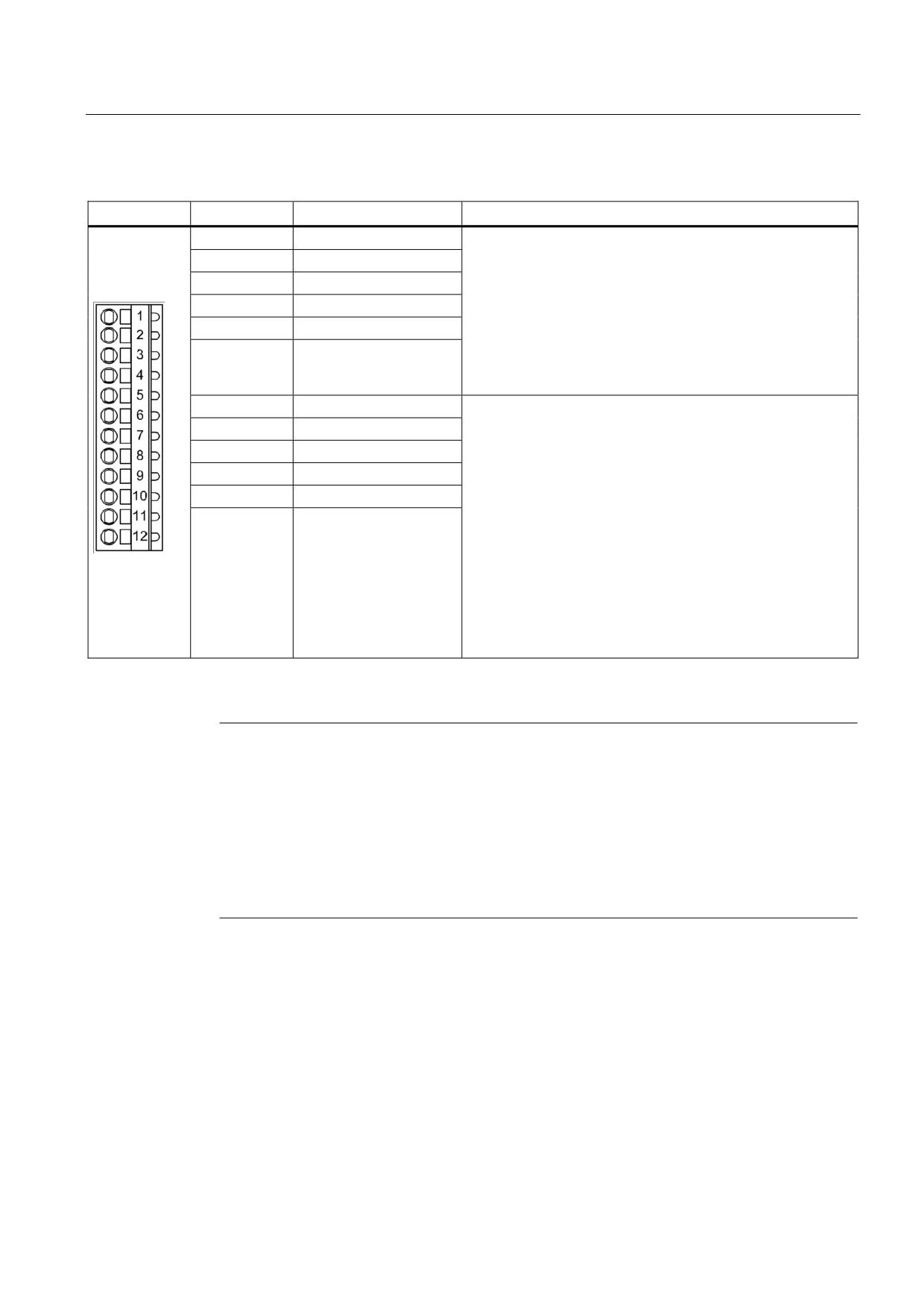
X122 digital inputs/outputs
When commissioning the drive wizard, the digital inputs/outputs are correspondingly
preassigned functions.
For more information about terminal assignment, see:
● The "Communication in the system" section of the "Machine Configuration Guidelines"
System Manual
● The "IBN CNC: NCK, PLC, Drive" Commissioning Manual ("Tips" section)
Table 9- 8
Interface characteristics of X122
Characteristics
Version
Connector type
Screw-type terminals
Connection option
Up to 0.5 mm2
Current carrying capacity
4 A max.
NCU 7x0.2
92
Manual, 02/2011, 6FC5397-0AP20-0BA0
Connectable components
9.1 NX10/15
Table 9- 9
Pin assignment for X122
Terminal
Designation 1)
Technical specifications
1
DI 0
Voltage: -3 V to 30 V
Typical current consumption: 10 mA at 24 V DC
2
DI 1
Isolation: The reference potential is terminal G1
3
DI 2
Level (incl. ripple)
4
DI 3
High level: 15 V to 30 V
5
G1
Low signal level: -3 V to 5 V
6
G
Signal propagation delays:
L → H: approx. 50 μs
H → L: approx. 100 µs
7
DI/DO 8
As input:
Voltage: -3 V to 30 V
8
DI/DO 9
Typical current consumption: 10 mA at 24 V DC
9
G
Level (incl. ripple)
10
DI/DO 10
High level: 15 V to 30 V
11
DI/DO 11
Low signal level: -3 V to 5 V
12
G
Terminal numbers 8, 10, and 11 are "rapid inputs"
Signal propagation delays for inputs/"rapid inputs":
L → H: approx. 50 μs/5 μs
H → L: approx. 100 μs/50 μs
As output:
Voltage: 24 V DC
Max. load current per output: 500 mA continuously short
circuit-proof
1) DI: digital input; DI/DO: Bidirectional digital input/output; G: Electronics ground G1: Ground reference
Note
An open input is interpreted as "low".
The "rapid inputs" can be used for position detection and as inputs of measuring inputs
depending on the terminal assignment used.
To enable digital inputs (DI) 0 to 3 to function, terminal G1 must be connected. This can be
done as follows:
Connect the coupled-motion ground reference of the digital inputs or provide a jumper to
terminal G. (Notice! This removes the galvanic isolation for these digital inputs.)
NCU 7x0.2
Manual, 02/2011, 6FC5397-0AP20-0BA0
93
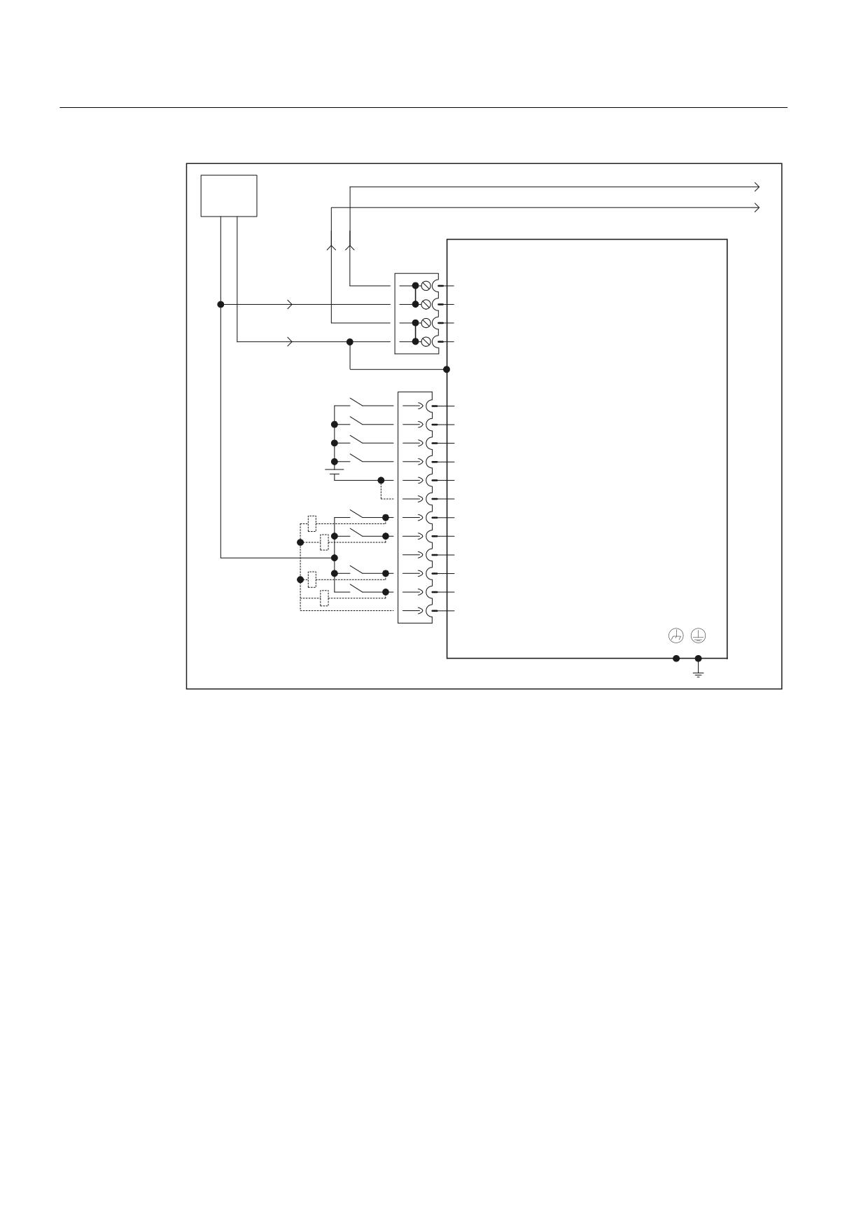
Connectable components
9.1 NX10/15
([W
9'&
0
0
;
9
1XPHULFDO ([WHQVLRQ 1;
0
0
0
0
;
5DSLG LQSXWV
',
PXVW EH VKLHOGHG
',
',
-XPSHU RSHQ JDOYDQLF LVRODWLRQ
IRU GLJLWDO LQSXWV ',
',
0
&DQ EH SDUDPHWHUL]HG DV
0
LQSXW RXWSXW
', '2
', '2
0
', '2
', '2
0
Figure 9-5
Block diagram for digital inputs/outputs
Additional references
For information on commissioning NX components, please refer to the "IBN CNC: NCK,
PLC, drive Commissioning Manual".
NCU 7x0.2
94
Manual, 02/2011, 6FC5397-0AP20-0BA0

Connectable components
9.2 COM01.2 RS 232C (V.24) module
9.1.5
Technical Data
Table 9- 10 Technical data
Parameters
Values
Input voltage
24 V DC (20.4 - 28.8)
Current (without DRIVE-CLiQ or digital outputs)
0.8 A
PE/ground connection
On housing with M5/3 Nm screw
Dimensions (WxHxD)
24.5 x 396 x 226 mm
Weight
1.5 kg
Mounting position
Vertical
9.2
COM01.2 RS 232C (V.24) module
9.2.1
Description
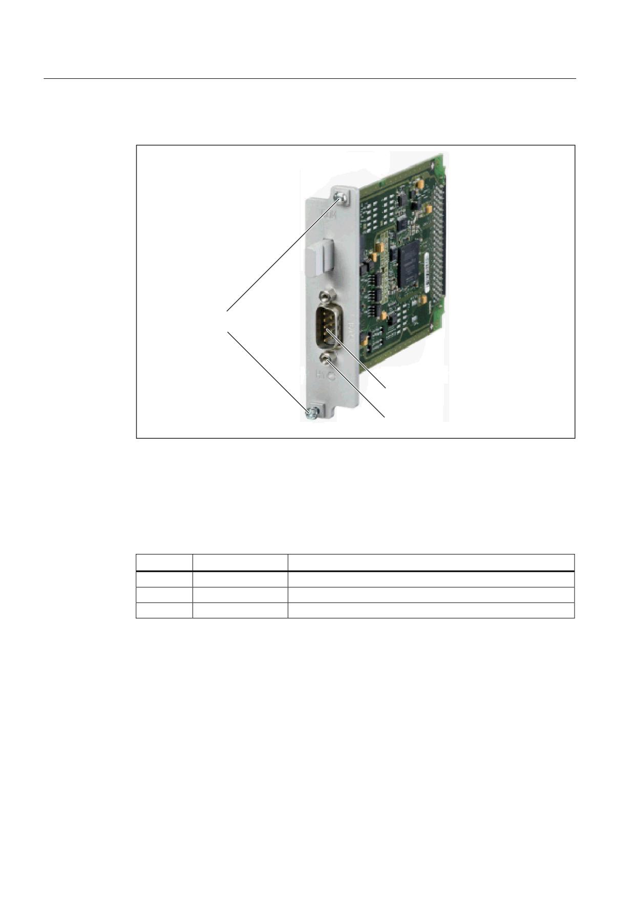
The Option Board COM01.2 RS 232C (V.24) module can be inserted into the option slot on
the following control units:
● NCU 710.2
● NCU 720.2
● NCU 730.2
The control units can be connected to a master computer or modem via COM port X491.
The COM port has been designed in accordance with the "ANSI/EIA/TIA-232-F-1997"
standard.
NCU 7x0.2
Manual, 02/2011, 6FC5397-0AP20-0BA0
95
Connectable components
9.2 COM01.2 RS 232C (V.24) module
Display
)L[LQJ VFUHZV
&20 SRUW ;
/(' + RSHUDWLQJ VWDWH
Figure 9-6
COM01.2 RS 232C (V.24) module
LED displays
LED H1 is located under the COM port. This can display the following operating states:
Table 9- 11 LED displays, H1
Color
Status
Meaning
Orange
lights up
COM01.2 is ready; after reset.
Green
lights up
COM01.2 is active.
Red
lights up
Operating error
NCU 7x0.2
96
Manual, 02/2011, 6FC5397-0AP20-0BA0
Connectable components
9.2 COM01.2 RS 232C (V.24) module
9.2.2
Installation/Mounting
CAUTION
Option boards should only be inserted and removed when the control unit and option board
are at zero current.
CAUTION
Option boards may only be operated by qualified personnel. The ESD notices must be
observed.
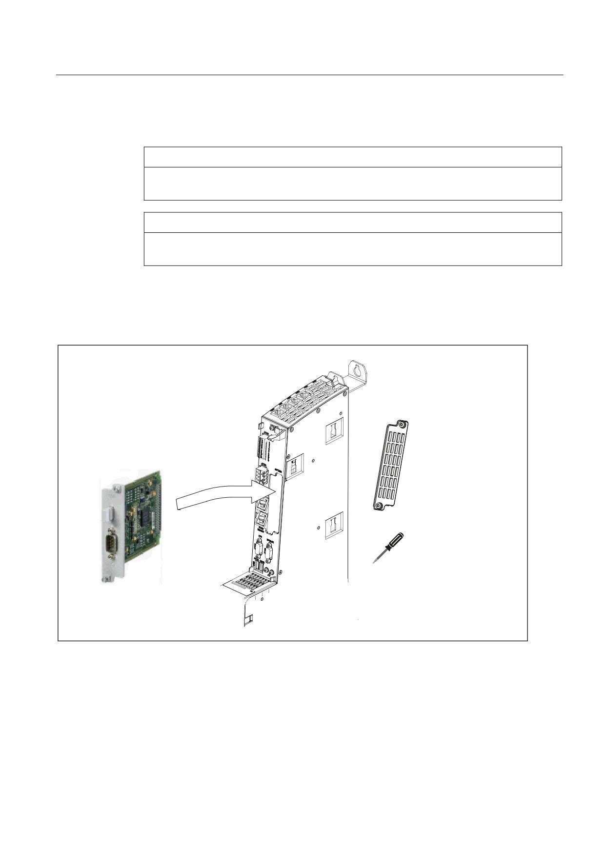
Installing the COM01.2 RS 232C (V.24) module
A COM01.2 option board is installed in the option slot of the control unit.
8QVFUHZ DQG UHPRYH WKH
SURWHFWLYH FRYHU
7RU[ 7
)L[LQJ VFUHZV
0
1P
,QVHUW DQG PRXQW WKH RSWLRQ
ERDUG
Figure 9-7
Installing COM01.2
The cable outlet is at the top.
NCU 7x0.2
Manual, 02/2011, 6FC5397-0AP20-0BA0
97
Connectable components
9.2 COM01.2 RS 232C (V.24) module
9.2.3
Connection
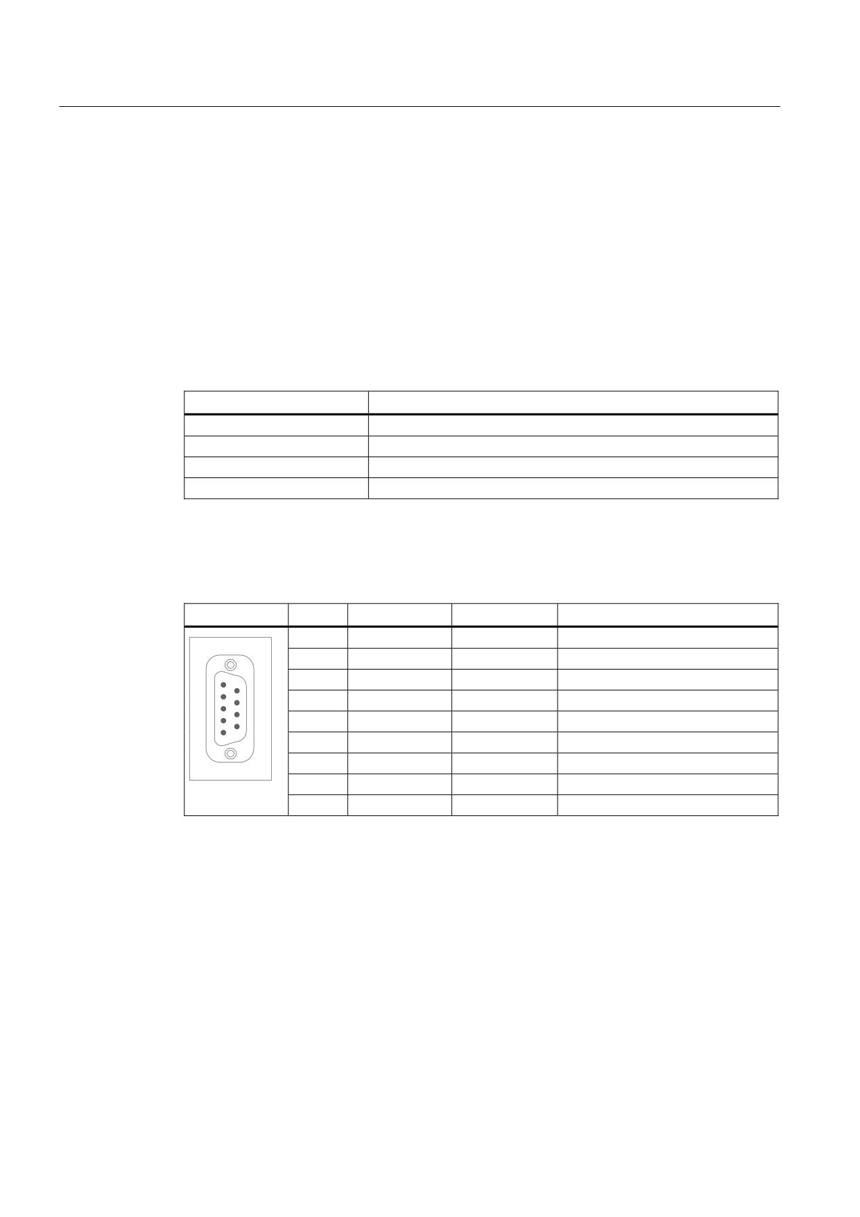
The RS 232C (V.24) module has a standardized serial interface.
Properties
COM port X491 is opto-uncoupled.
Cable specification
Table 9- 12 Cable specification for COM port X491
Characteristic
Specification
Connector type
9-pin SUB-D socket; pin
Cable type
Prefabricated signal line RS 232C/V.24 (9-pin - 9-pin)
Order number
6FX8002-1AA01
Max. cable length
15 m
Pin assignment
Table 9- 13 COM port X491
Pin
Signal name
Signal type
Meaning
1
DCD
Input
Receiver signal level
2
RXD
Input
Serial receive data
3
TXD
Output
Serial transmit data
4
DTR
Output
Data terminal equipment ready
5
GND
-
Ground (reference potential)
6
DSR
Input
Readiness for operation
7
RTS
Output
Request To Send
8
CTS
Input
Clear To Send
9
RI
Input
Incoming call
NCU 7x0.2
98
Manual, 02/2011, 6FC5397-0AP20-0BA0

Connectable components
9.3 TM15 Terminal Module
9.3
TM15 Terminal Module
Properties
Terminal Module TM15 provides drive-related digital inputs and outputs with short signal
delay times. TM15 is connected by means of DRIVE-CLiQ.
Each of the 24 isolated DI/DOs can be parameterized channel-by-channel as a digital input
(DI) or digital output (DO).
Additional references
You can find additional information on the TM15 in the SINAMICS S120 manual titled
"control units and Additional System Components".
CAUTION
The cooling clearances of 50 mm above and below the component must be observed.
9.4
DRIVE-CLiQ Hub Module DMC20
Properties
The DRIVE-CLiQ DMC20 Hub Module is used to implement point-to-point distribution of a
DRIVE-CLiQ line. With the DMC20, an axis grouping can be expanded with 4 DRIVE-CLiQ
sockets for additional subgroups.
The module is especially suitable for applications which require DRIVE-CLiQ nodes to be
removed in groups, without interrupting the DRIVE-CLiQ line and therefore the data
exchange.
CAUTION
The cooling clearances of 50 mm above and below the component must be observed.
Additional references
You can find further information on the DMC20 in the SINAMICS S120 manual titled "Control
Units and Additional System Components".
NCU 7x0.2
Manual, 02/2011, 6FC5397-0AP20-0BA0
99
Connectable components
9.5 DME20 DRIVE-CLiQ Hub Module
9.5
DME20 DRIVE-CLiQ Hub Module
Properties
The DME20 DRIVE-CLiQ Hub Module is used to implement point-to-point distribution of a
DRIVE-CLiQ line. With the DME20, an axis grouping can be expanded with 5 DRIVE-CLiQ
sockets for additional subgroups.
The component has degree of protection IP67 and is especially suitable for applications
which require DRIVE-CLiQ nodes to be removed in groups, without interrupting the DRIVE-
CLiQ line and therefore the data exchange.
The DME20 can be used with SINAMICS firmware version 2.6 or higher.
CAUTION
The cooling clearances of 50 mm above and below the component must be observed.
Additional references
You can find further information on the DME20 in the SINAMICS S120 manual titled "Control
Units and Additional System Components".
NCU 7x0.2
100
Manual, 02/2011, 6FC5397-0AP20-0BA0
Spare Parts/Accessories
10
10.1
Dual fan/ battery module
10.1.1
Application
Functions of the dual fan/battery module
The dual fan/battery module can perform the following tasks:
● Cooling the CPU by means of two redundant fans.
● SRAM buffering if the SuperCap is insufficient.
The Control Unit monitors the temperature inside the module and the functioning of the fan.
Fan faults are displayed and can be read out by means of the diagnostic buffer.
● Fan warning: When one of the two fans has ceased to turn.
● Fan fault: When none of the fans turn.
If the software does not respond within approx. 1 minute the components are shutdown
automatically and the status is indicated by means of the red SF LED.
Fans
If natural convection is not sufficient to ensure heat dissipation for the the
NCU 710.2/720.2/730.2, the fans integrated in the dual fan/battery module will be activated
when required.
● After switching the NCU on, the fan will be activated for a brief period (for testing
purposes) before turning itself off again.
● A temperature sensor on the NCU will switch the fan on if the air intake temperature
exceeds approximately 40°C.
● The fans will be switched off when the air intake temperature falls back below approx.
35°C.
● The fan is monitored during operation. In the event of a fault (stalled rotor or running too
slowly) a message is output.
Fans on the following Control Units run permanently:
NCU 720.2 PN and NCU 730.2 PN
NOTICE
The Control Unit cannot be operated without fans, i.e. the Control Unit will not power up if
the dual fan/battery module is not functioning.
NCU 7x0.2
Manual, 02/2011, 6FC5397-0AP20-0BA0
101
Spare Parts/Accessories
10.1 Dual fan/ battery module
Battery
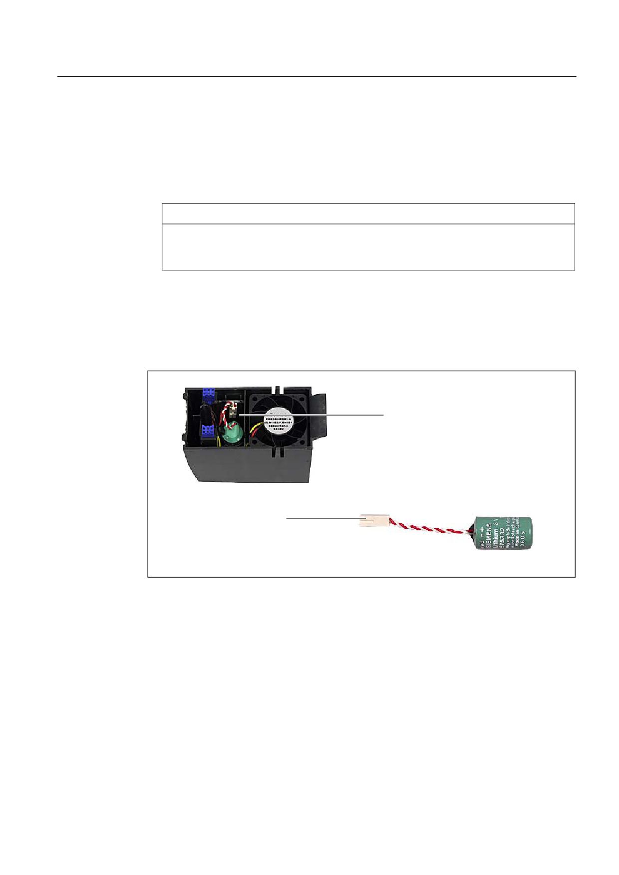
A 3 V lithium battery can be inserted in the dual fan/battery module. The battery is pre-
assembled with an approximately 4 cm long cable with plug connector. The appropriate
mating connector is attached to a small circuit board for connection in the dual fan/battery
module.
Note
Please dispose of used batteries in the specially provided collection points on site. This will
ensure they are reused in the correct manner or treated as special waste.
NOTICE
The backup time of a used type of battery is at least 3 years. Exceeding this backup time
risks loss of data.
10.1.2
Mounting
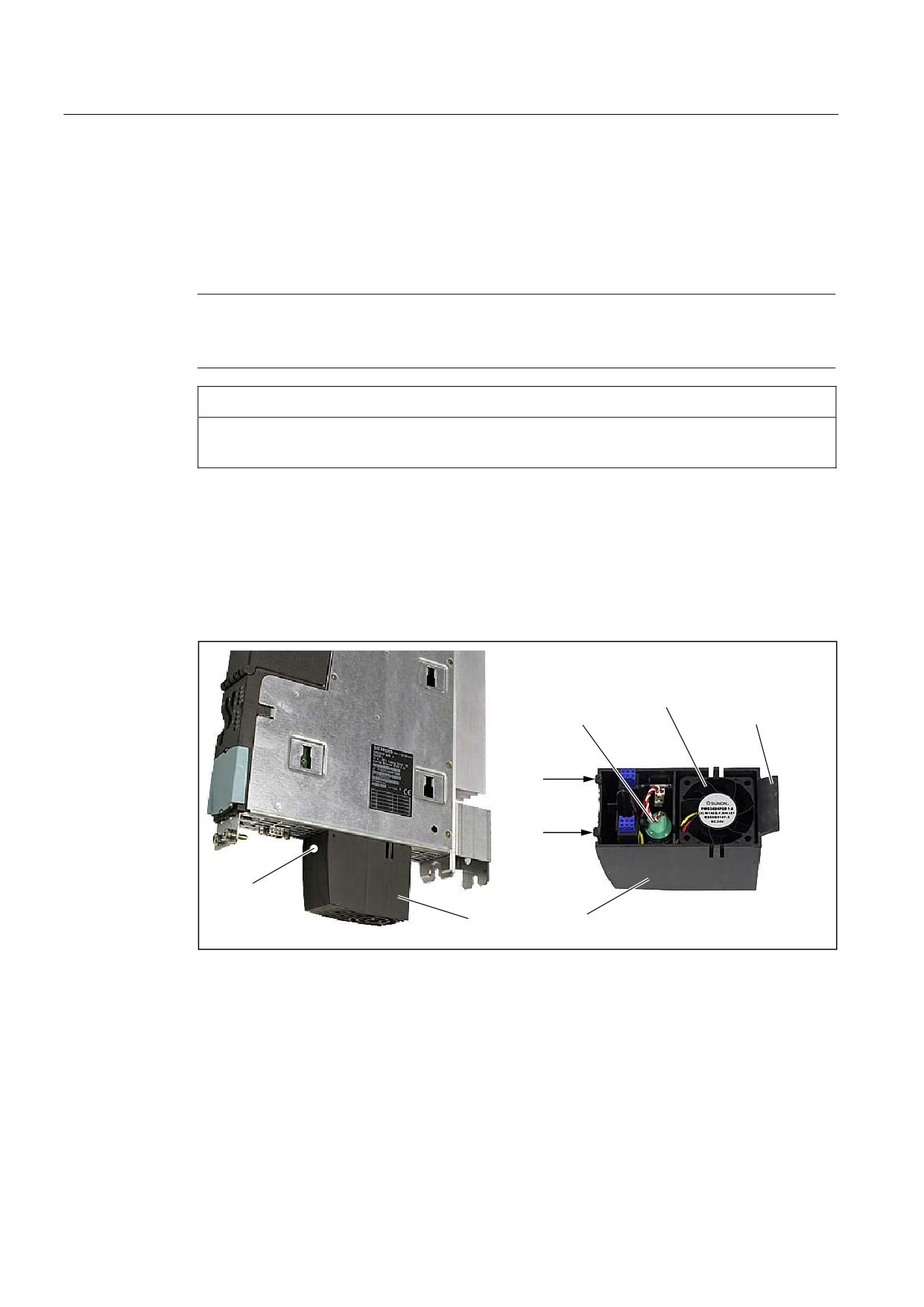
Position of the dual fan/battery module
)DQV
%DWWHU\
3ODVWLF JXLGH
6QDS LQ KRRN
3UHVVXUH SRLQW
'XDO IDQ EDWWHU\ PRGXOH
Figure 10-1 Replacing the dual fan/ battery module
NCU 7x0.2
102
Manual, 02/2011, 6FC5397-0AP20-0BA0
Spare Parts/Accessories
10.1 Dual fan/ battery module
Procedure
Proceed as follows to replace the dual fan/battery module but only observe points 3 and 4 if
you want to replace the battery as well:
1. Gently push the dual fan/battery module backwards (by pressing on the pressure point) to
release the module from its front interlock (snap-in hooks).
CAUTION
Never pull the dual fan/battery module out abruptly without having released the
interlock. This would break the snap-in hooks and you would not be able to reinsert the
module.
2. Tilt the dual fan/battery module forwards at an angle and pull out the plastic guide from
the Control Unit cutout.
3. Remove the battery by first removing the plug connector and then taking out the battery.
4. Connect the cable plug connector of the new battery to the mating connector in the dual
fan/battery module and push the battery in.
&RQQHFWLRQ IRU
EDWWHU\ FDEOH FRQQHFWRU
%DWWHU\
FDEOH FRQQHFWRU
Figure 10-2 Battery replacement in the dual fan/battery module
5. Tilt the dual fan/battery module forwards at an angle with the open side facing up (battery
visible).
NCU 7x0.2
Manual, 02/2011, 6FC5397-0AP20-0BA0
103

Spare Parts/Accessories
10.2 CompactFlash Card
6. Push the plastic guide into the cutouts on the underside of the Control Unit.
7. Tilt the dual fan/battery module up until the front interlock snaps into place.
The electrical connection between the dual fan/battery module and the Control Unit is
established automatically.
NOTICE
To avoid loss of data, the dual fan/battery module must be replaced during operation.
When doing this, observe that the Control Unit can only be operated for a maximum of 1
minute without fans. If this time is exceeded, the Control Unit will shut itself down.
10.2
CompactFlash Card
10.2.1
Properties
Application
The CompactFlash Card is delivered bootable. It is not supplied with the control unit and
must be ordered as a separate component.
The CompactFlash Card is inserted in the CF plug-in slot (X109 interface).
CAUTION
The CompactFlash Card may only be inserted or removed when the control unit is
disconnected from the power supply.
Data
The CompactFlash Card is mandatory for operation of the control unit.
As well as the basic software for SINUMERIK and the firmware for SINAMICS, the
CompactFlash Card also contains:
● User data (programs, configuration data, parameter settings)
● Version info (serial number, version, type designation)
● License key This means that the CompactFlash Card can be inserted into another control
unit without requiring a license change.
NCU 7x0.2
104
Manual, 02/2011, 6FC5397-0AP20-0BA0
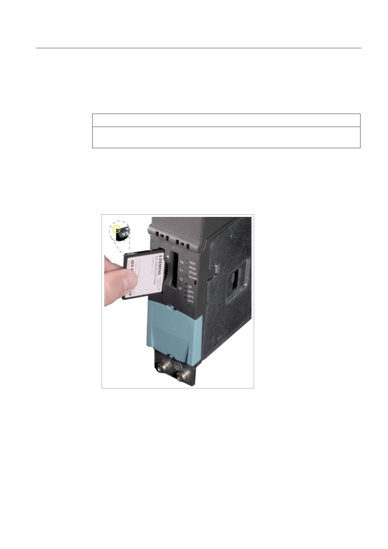
Spare Parts/Accessories
10.2 CompactFlash Card
10.2.2
Inserting the CompactFlash card
Proceed as follows
NOTICE
ESD: you must discharge yourself at the cabinet or ground terminal before touching the
CompactFlash Card.
Please proceed as follows:
1. Switch off the power supply.
2. Gently insert the new CompactFlash Card into the plug-in slot until it clicks into place.
When properly installed, the card does not extend beyond the housing.
3. Switch the power supply on again.
Figure 10-3 Inserting the CompactFlash card
NCU 7x0.2
Manual, 02/2011, 6FC5397-0AP20-0BA0
105