SINUMERIK 840D sl Hardware. Manual (2011-2020) - page 17
Connectable components
9.5 CBE30-2
Properties
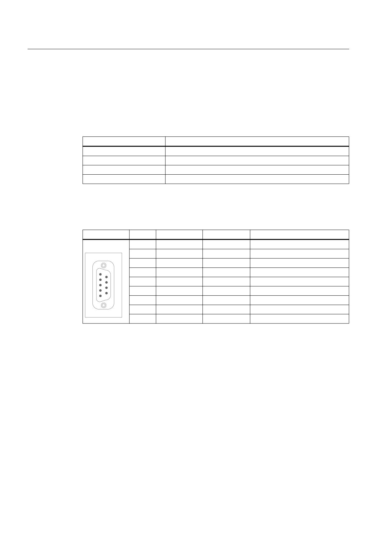
COM port X491 is opto-uncoupled.
Cable specification
Table 9-72
Cable specification for COM port X491
Characteristic
Version
Connector type
9-pin SUB-D socket; pin
Cable type
Prefabricated signal line RS 232C/V.24 (9-pin - 9-pin)
Order number
6FX8002-1AA01
Max. cable length
15 m
Pin assignment
Table 9-73
COM port X491
Pin
Signal name
Signal type
Meaning
1
DCD
Input
Receiver signal level
2
RXD
Input
Serial receive data
3
TXD
Output
Serial transmit data
4
DTR
Output
Data terminal equipment ready
5
GND
-
Ground (reference potential)
6
DSR
Input
Readiness for operation
7
RTS
Output
Request To Send
8
CTS
Input
Clear To Send
9
RI
Input
Incoming call
9.5
CBE30-2
9.5.1
Description
With the CBE30-2 Ethernet communication board, based on the generally released standard
configuration, an NCU link communication with a maximum of three NCUs can be configured.
Additional NCUs can be integrated into the link communication on a project-for-project basis
when regional Siemens partners are contacted.
NCU 7x0.3 PN, NCU 7x0.3B PN
148
Manual, 06/2014, 6FC5397-1EP40-5BA1
Connectable components
9.5 CBE30-2
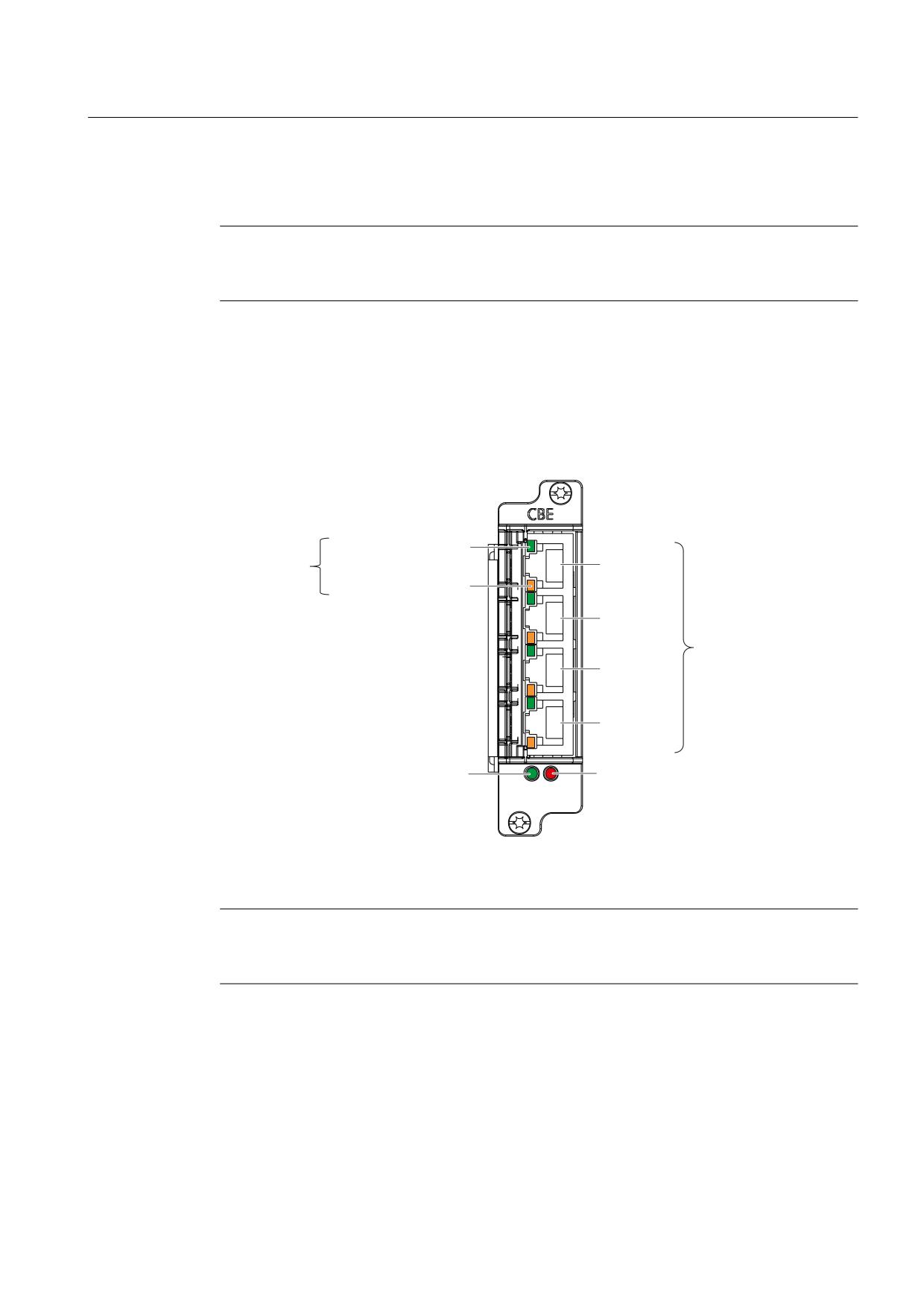
When using a CBE30-2, the NCU is assigned an additional interface X1400, comprising 4
PROFINET ports. The NCU-Link is permanently wired via port 1 (in) and port 2 (out).
Note
The Communication Board Ethernet CBE30-2 cannot be used for the NCU730.3B PN with
PLC 319 DP/PN.
Additional references
For further information, please refer to the Function Manual Extended Functions, B3, Chapter
"Link communication".
Illustration
/LQN SRUW JUHHQ
/('V SHU SRUW
3RUW
$FWLYLW\ SRUW RUDQJH
3RUW
;
3RUW
3RUW
/(' V\QF JUHHQ
/(' IDXOW UHG
Figure 9-23 CBE30-2 Ethernet communication board
Note
The NCU link communication is exclusively operated using ports 1 and 2. Ports 3 and 4 cannot
be used and are not freely available.
NCU 7x0.3 PN, NCU 7x0.3B PN
Manual, 06/2014, 6FC5397-1EP40-5BA1
149
Connectable components
9.5 CBE30-2
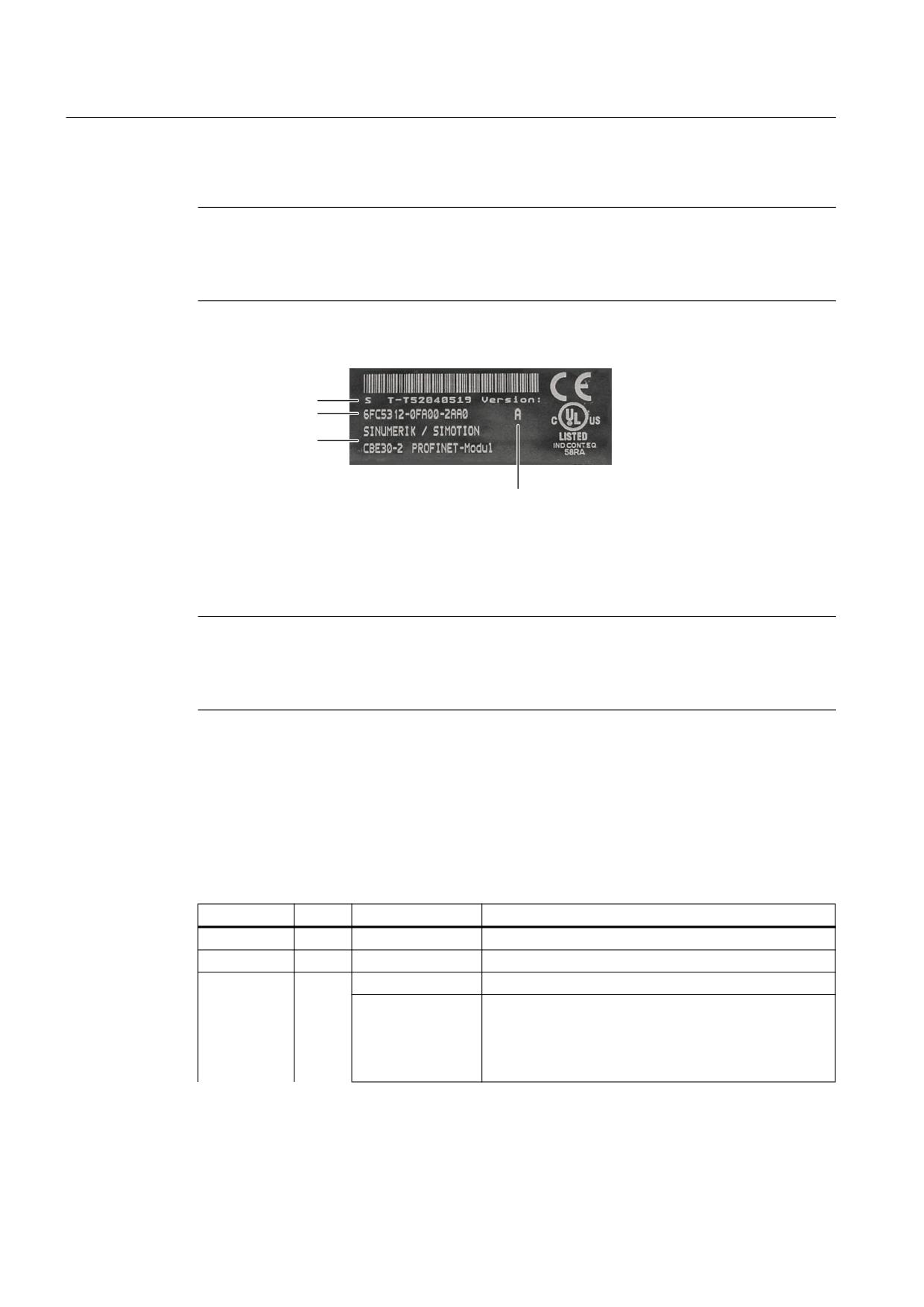
Type plate
Note
You might need to access the information provided on the type plate after mounting. Since
the type plate after mounting the option board can no longer be read, we recommend that
you at least note down the serial number before mounting.
The following diagram shows you all of the information provided on the type plate.
Serial number
Order number
Module designation
HW version
Figure 9-24 CBE30-2 type plate
This plate is only visible, when the option board has been removed; it is attached to the
underside of the option board.
Note
The contents of the individual type plate fields on the actual option board may differ from
those described in this manual (e.g. updated product status, approvals and markings not yet
issued, etc.).
LED displays
The four ports of the X1400 interface provide integrated LEDs for displaying the link and the
activity. The front panel of the CBE30-2 is also fitted with two LEDs (Fault and Sync), which
indicate the bus status.
Table 9-74
LED displays
Name
Color
Status
Meaning
Link port
Green
lit
The physical connection exists.
Activity port
Yellow
lit
Data is being received or transmitted.
Fault
Red
off
CBE runs without errors, data is being exchanged.
lit
Bus fault:
● No physical connection to a subnet/switch
● Incorrect transmission rate
● Full duplex transmission is not activated.
NCU 7x0.3 PN, NCU 7x0.3B PN
150
Manual, 06/2014, 6FC5397-1EP40-5BA1

Connectable components
9.5 CBE30-2
Name
Color
Status
Meaning
flashing (2 Hz)
● Failure of a connected NCU
● At least one of the assigned NCUs cannot be
addressed
● Incorrect or no configuration.
Sync
Green
off
Clock cycle system of the NCU is not synchronized to
the send cycle. An internal substitute clock of the same
size as the send clock is generated.
lit
Clock cycle system of the NCU has synchronized to the
send cycle and data exchange is running.
flashing (0.5 Hz)
Clock cycle system of the NCU has synchronized to the
send cycle and cyclic data exchange is running.
9.5.2
Installation/Mounting
NOTICE
Damage to the option board by inserting and withdrawing in operation
● Option boards should only be inserted and removed when the NCU and option board are
in a no-current condition.
● Option boards may only be operated by qualified personnel. The ESD notices must be
observed.
NCU 7x0.3 PN, NCU 7x0.3B PN
Manual, 06/2014, 6FC5397-1EP40-5BA1
151
Connectable components
9.5 CBE30-2
Installing the CBE30-2
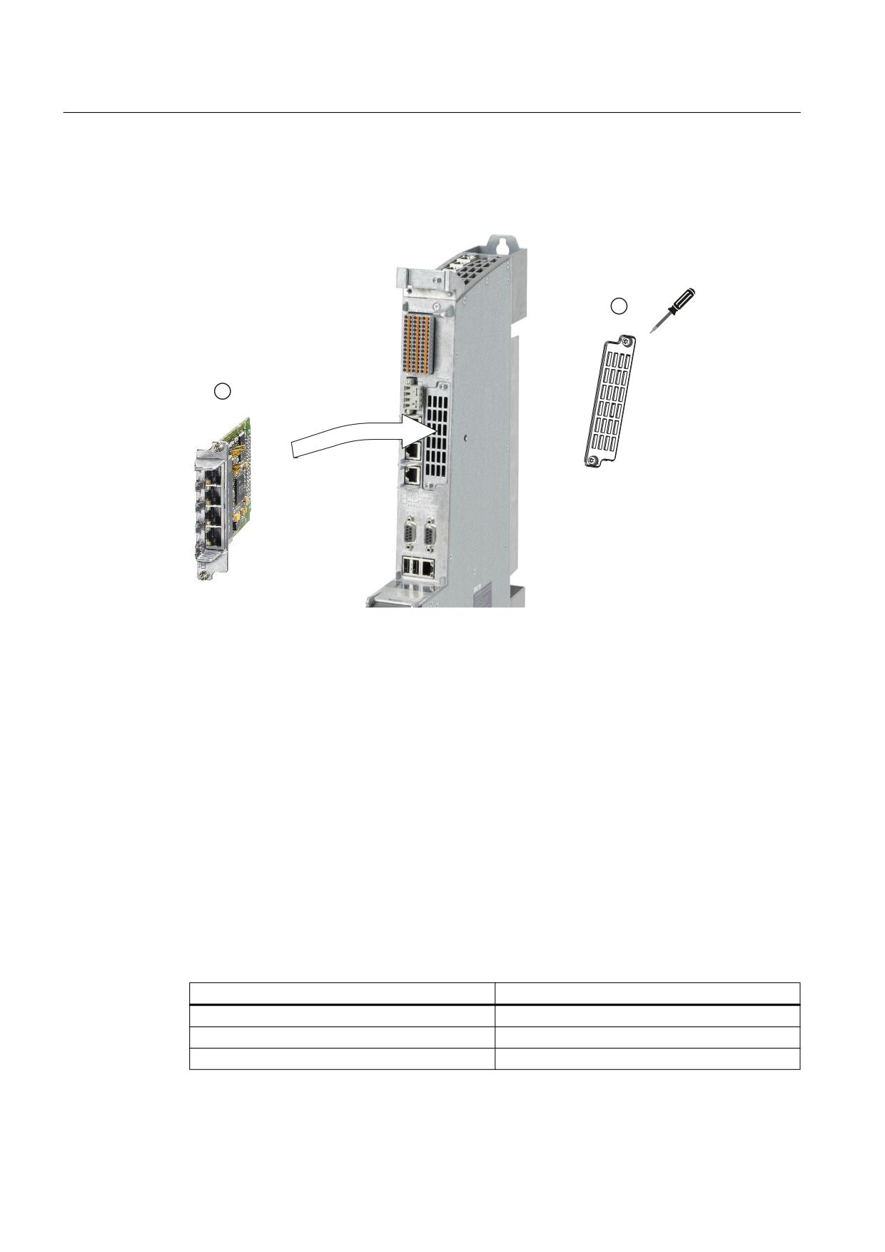
A CBE30-2 is installed in the option slot of the NCU.
① Release the M3 fixing screws and remove the protective cover.
② Insert and secure the option board.
Tightening torque of the M3 fixing screws: 0.8 Nm.
Figure 9-25 Installing the CBE30-2
9.5.3
Connection
Properties
The X1400 interface has full-duplex 10/100-Mbit Ethernet ports with autocrossing. The module
has an integrated 4-port switch.
Interface characteristics
Table 9-75
X1400
Characteristic
Version
Connector type
RJ45 socket*)
Cable type
Industrial Ethernet cable (CAT5)
Max. cable length
100 m
NCU 7x0.3 PN, NCU 7x0.3B PN
152
Manual, 06/2014, 6FC5397-1EP40-5BA1
Connectable components
9.5 CBE30-2
*) Please use the Fast Connect connector as described in Chapter "PROFINET cables
(Page 60)".
Pin assignment
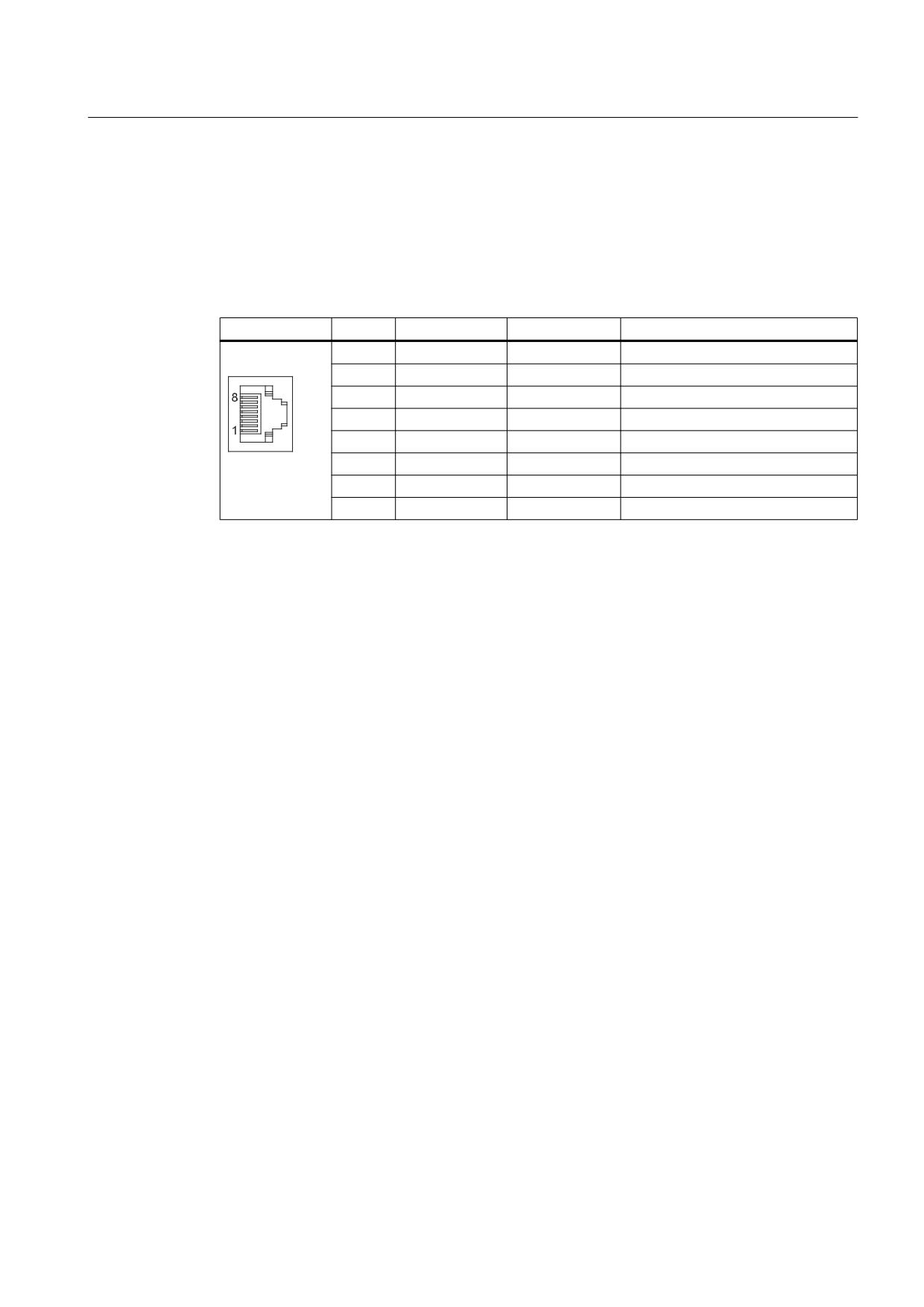
Table 9-76
X1400 interface, ports 1 - 4
Pin
Signal name
Signal type
Meaning
1
TX+
Output
Transmit data +
2
TX-
Output
Transmit data -
3
RX+
Input
Receive data +
4
NC
5
NC
6
RX-
Input
Receive data -
7
NC
8
NC
NCU 7x0.3 PN, NCU 7x0.3B PN
Manual, 06/2014, 6FC5397-1EP40-5BA1
153
Spare Parts/Accessories
10
10.1
Replacing the dual fan/ battery module
Procedure
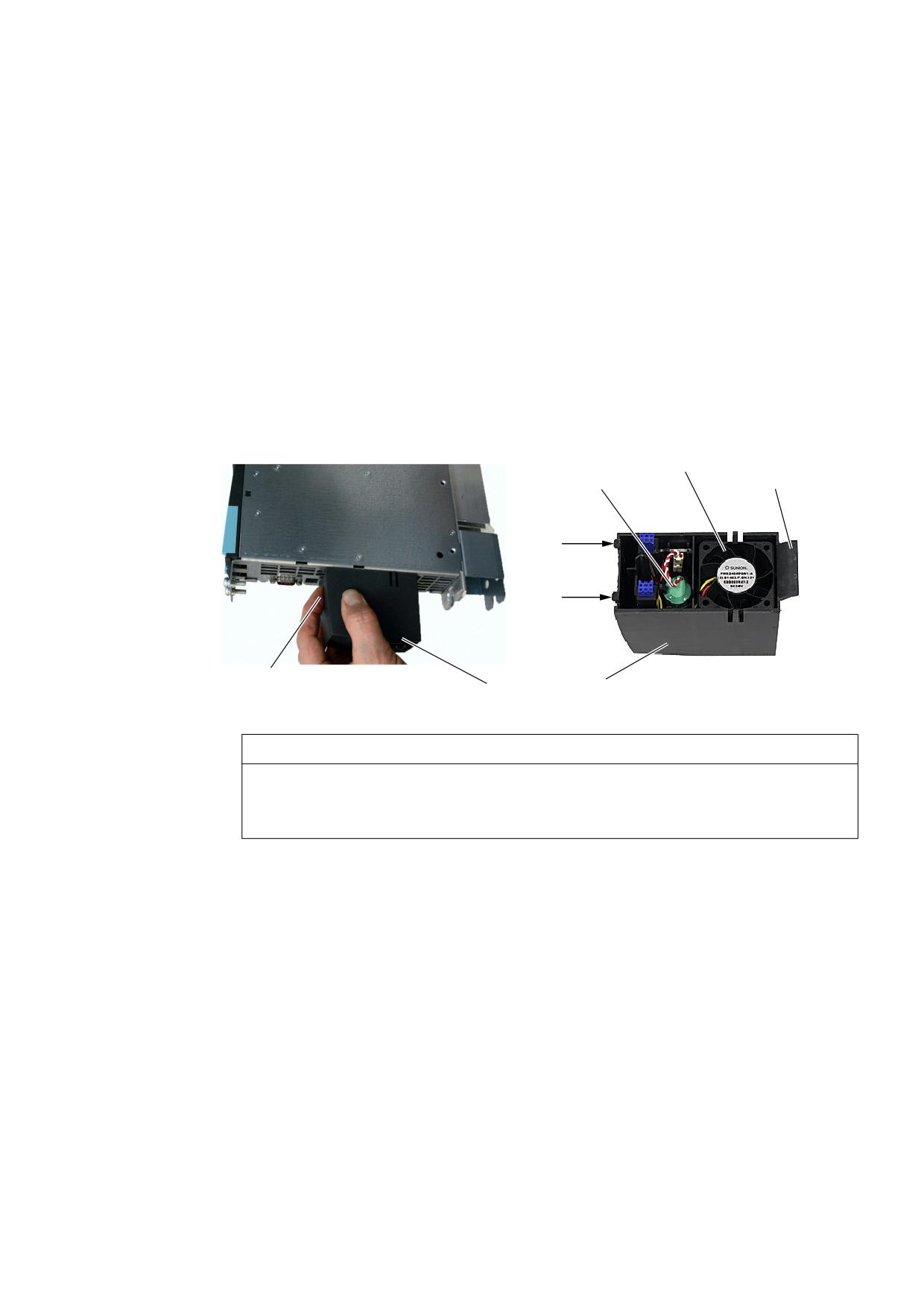
Proceed as follows to replace the dual fan/battery module but only observe points 3 and 4 if
you want to replace the battery as well:
1. Gently push the dual fan/battery module backwards (by pressing on the pressure point) to
release the module from its front interlock (snap-in hooks).
)DQV
%DWWHU\
3ODVWLF JXLGH
/RFNLQJ ODWFK
3RVLWLYH FOLFN DFWLRQ
'XDO IDQ EDWWHU\ PRGXOH
NOTICE
Forcibly withdrawing the module can permanently damage it
Never pull the dual fan/battery module out abruptly without having released the interlock.
This would break the snap-in hooks and you would not be able to reinsert the module.
2. Tilt the dual fan/battery module forward at an angle and pull out the plastic guide from the
NCU cutout.
3. Remove the battery by first removing the plug connector and then taking out the battery.
NCU 7x0.3 PN, NCU 7x0.3B PN
Manual, 06/2014, 6FC5397-1EP40-5BA1
155
Spare Parts/Accessories
10.1 Replacing the dual fan/ battery module
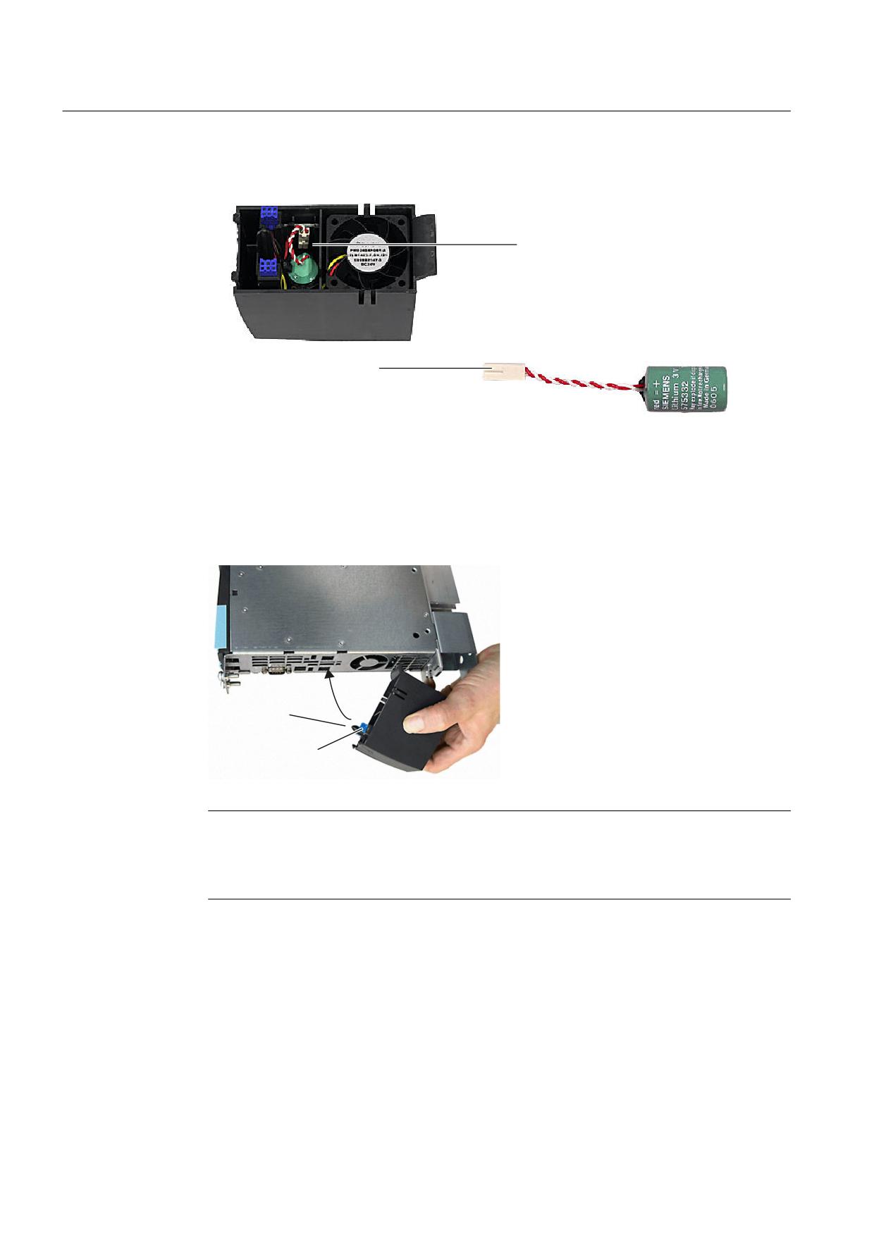
4. Connect the cable plug connector of the new battery to the mating connector in the dual
fan/battery module and push the battery in.
&RQQHFWLRQ IRU
EDWWHU\ FDEOH FRQQHFWRU
%DWWHU\
FDEOH FRQQHFWRUV
Figure 10-1 Battery replacement in the dual fan/battery module
5. Tilt the dual fan/battery module forwards at an angle with the open side facing up (battery
visible).
6. Push the plastic guide into the cutouts on the underside of the NCU.
7. Tilt the dual fan/battery module up until the front interlock snaps into place. The electrical
connection between the dual fan/battery module and the NCU is established automatically.
6SLJRW
&RQWDFW VWULS
Note
The dual fan/battery module can be replaced during operation. If you choose to do this,
remember that the NCU can only be operated for a maximum of 1 minute without fans. If
this time is exceeded, it will shut itself down.
NCU 7x0.3 PN, NCU 7x0.3B PN
156
Manual, 06/2014, 6FC5397-1EP40-5BA1

Spare Parts/Accessories
10.2 CompactFlash Card
10.2
CompactFlash Card
10.2.1
Properties of the CompactFlash card
Application
The CompactFlash Card is delivered bootable. It is not supplied with the NCU and must be
ordered as a separate component.
The CompactFlash Card is inserted in the CF plug-in slot (X109 interface).
NOTICE
Inserting or withdrawing with the power connected can destroy the CF card
The CompactFlash Card may only be inserted or removed when the control unit is
disconnected from the power supply.
Data
The CompactFlash card is mandatory for operation of the NCU.
As well as the basic software for SINUMERIK and the firmware for SINAMICS, the
CompactFlash Card also contains:
● User data (programs, configuration data, parameter settings)
● Version info (serial number, version, type designation)
● License key This means that the CompactFlash card can be inserted into another NCU
without having to change the license.
10.2.2
Inserting the CompactFlash card
Procedure
Note
ESD: you must discharge yourself at the cabinet or ground terminal before touching the
CompactFlash Card.
Please proceed as follows:
1. Switch off the power supply.
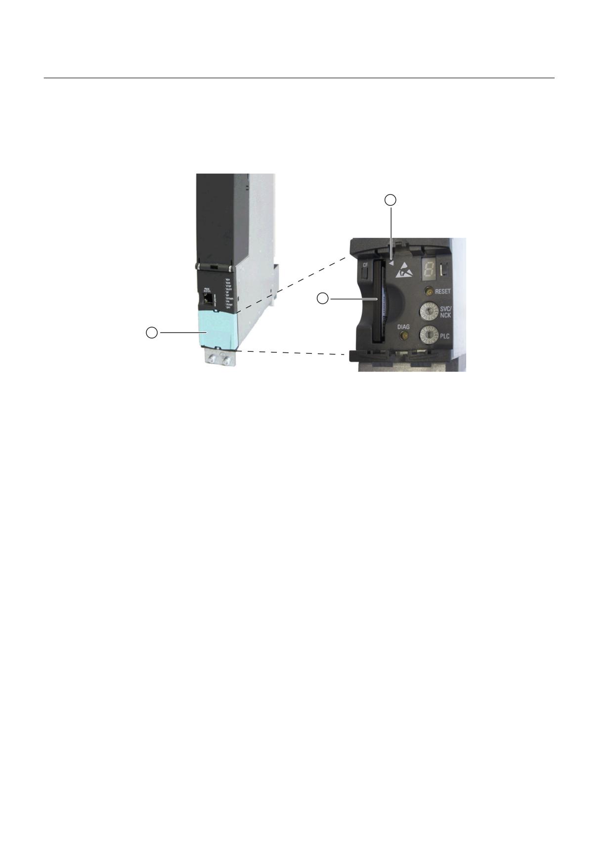
2. Remove the blanking cover ①.
NCU 7x0.3 PN, NCU 7x0.3B PN
Manual, 06/2014, 6FC5397-1EP40-5BA1
157
Spare Parts/Accessories
10.2 CompactFlash Card
3. Carefully insert the new CompactFlash Card
② into the slot until it clicks into place. The
marking ③ provided on the CompactFlash Card is used as orientation: the two arrow heads
point to one another. When properly installed, the card does not extend beyond the housing.
4. Switch the power supply on again.
① Blanking plate
② CompactFlash Card
③ Marking for insertion direction
Figure 10-2 Inserting the CompactFlash card
NCU 7x0.3 PN, NCU 7x0.3B PN
158
Manual, 06/2014, 6FC5397-1EP40-5BA1

Appendix
A
A.1
Abbreviations
AWG
American Wire Gauge
B-MPI
Handheld unit with MPI connection
BERO
Proximity limit switch
CAT5
Quality class (category) for shielded twisted-pair cables. Class 5 states that these cables have a particularly
low damping factor, making them suitable for 100 Mbit/s-FastEthernet networks.
CBA
Component Based Automation: Component Based Automation
CNC
Computerized Numerical Control Computerized numerical control
CPU
Central Processing Unit Central processing unit
CRC
Cyclic redundancy check: Checksummenprüfung
DCP
Discovery and basic Configuration Protocol (standard for assigning IP addresses)
DIN
Deutsche Industrie Norm (German Industry Standard)
DIP
Dual In-Line Package: Dual in-line arrangement
DP
Distributed I/O
DRAM
Dynamic Random Access Memory
DRIVE-CLiQ
Drive Component Link with IQ
EGB
Electrostatic Sensitive Devices
EMC
Electromagnetic compatibility
EN
European standard
ESD
Electrostatic discharge: elektrostatische Entladung
HMI
Human Machine Interface: SINUMERIK operator interface for operating, programming and simulation
HSC
High-Speed Cutting
HT
Handheld Terminal
LED
Light-emitting diode light-emitting-diode display
MAC
Media Access Control
MCP
Machine Control Panel
MPI
Multi-Point Interface Multi-point interface
MPP
Machine Push Button Panel
NCK
Numerical Control Kernel: NC kernel with block preparation, traversing range, etc.
NCU
Numerical Control Unit: NCK hardware unit
NVM
Non-Volatile Memory: non-volatile memory
NX
Numerical eXtension (axis extension module)
OP
Operator Panel : Operator panel front
PCU
PC Unit: Computer unit
PG
Programming device
PLC
Programmable Logic Control: Programmable logic control (component of the CNC controller)
PN
PROFINET
RAM
Random Access Memory: Program memory which can be read and written into
NCU 7x0.3 PN, NCU 7x0.3B PN
Manual, 06/2014, 6FC5397-1EP40-5BA1
159

Appendix
A.1 Abbreviations
TCU
Thin Client Unit (communication with operator panels)
TS
Teleservice
VDE
Association of Electrical Engineering, Electronics and Information Technology (Germany)
Full duplex
An Ethernet/PROFINET port can simultaneously transmit and receive data.
NCU 7x0.3 PN, NCU 7x0.3B PN
160
Manual, 06/2014, 6FC5397-1EP40-5BA1
Preface
Security instructions
1
Communication services and
2
used port numbers
SINUMERIK
SINUMERIK ONE / 840D sl
Port lists
Product Information
Valid for:
CNC Software Versions 4.9x / 6.1x
05/2020
A5E49960416B AA
Preface
SINUMERIK documentation
The SINUMERIK documentation is organized into the following categories:
● General documentation/catalogs
● User documentation
● Manufacturer/service documentation
Additional information
You can find information on the following topics at the following address (https://
support.industry.siemens.com/cs/de/en/view/108464614):
● Ordering documentation/overview of documentation
● Additional links to download documents
● Using documentation online (find and search in manuals/information)
If you have any questions regarding the technical documentation (e.g. suggestions,
corrections), please send an e-mail to the following address
(mailto:docu.motioncontrol@siemens.com).
mySupport/Documentation
you can find information on how to create your own individual documentation based on
Siemens' content, and adapt it for your own machine documentation.
Training
SITRAIN (Siemens training on products, systems and solutions for automation and drives).
FAQs
You can find Frequently Asked Questions in the Service&Support pages under Product
SINUMERIK
You can find information about SINUMERIK at the following address (https://
Port lists
Product Information, 05/2020, A5E49960416B AA
3
Preface
Target group
This brochure is intended for use by planners, configuration engineers, technologists,
installation personnel, constructors, repair technicians, machine operators, programmers,
service and maintenance personnel
Benefits
Product information imparts knowledge about the current enhancements to and restrictions on
products and systems which are not described in the associated documentation.
Standard scope
This documentation only describes the functionality of the standard version. Additions or
revisions made by the machine manufacturer are documented by the machine manufacturer.
Other functions not described in this documentation might be executable in the control. This
does not, however, represent an obligation to supply such functions with a new control or when
servicing.
For the sake of simplicity, this documentation does not contain all detailed information about all
types of the product and cannot cover every conceivable case of installation, operation, or
maintenance.
Note regarding the General Data Protection Regulation
Siemens observes standard data protection principles, in particular the principle of privacy by
design. That means that
this product does not process / store any personal data, only technical functional data (e.g. time
stamps). If a user links this data with other data (e.g. a shift schedule) or stores personal data
on the same storage medium (e.g. hard drive) and thus establishes a link to a person or
persons, then the user is responsible for ensuring compliance with the relevant data protection
regulations.
Technical Support
Country-specific telephone numbers for technical support are provided in the Internet at the
area.
EC Declaration of Conformity
The EC Declaration of Conformity for the EMC Directive can be found on the Internet at the
following address (https://support.industry.siemens.com/cs/https://
support.industry.siemens.com/cs/ww/de/ps/14604/certww/en/ps/13231/cert).
Port lists
4
Product Information, 05/2020, A5E49960416B AA
Table of contents
Preface
3
1
Security instructions
7
1.1
Fundamental safety instructions
7
1.1.1
General safety instructions
7
1.1.2
Warranty and liability for application examples
7
1.1.3
Security information
7
2
Communication services and used port numbers
9
2.1
Overview
9
2.2
SINUMERIK ONE - NCU communication services and port numbers
10
2.3
Communication services and port numbers: 840D sl - NCU
15
2.4
Communication services and port numbers: 840D sl / ONE - IPC
17
Port lists
Product Information, 05/2020, A5E49960416B AA
5

Security instructions
1
1.1
Fundamental safety instructions
1.1.1
General safety instructions
WARNING
Danger to life if the safety instructions and residual risks are not observed
If the safety instructions and residual risks in the associated hardware documentation are not
observed, accidents involving severe injuries or death can occur.
● Observe the safety instructions given in the hardware documentation.
● Consider the residual risks for the risk evaluation.
WARNING
Malfunctions of the machine as a result of incorrect or changed parameter settings
As a result of incorrect or changed parameterization, machines can malfunction, which in turn
can lead to injuries or death.
● Protect the parameterization against unauthorized access.
● Handle possible malfunctions by taking suitable measures, e.g. emergency stop or
emergency off.
1.1.2
Warranty and liability for application examples
Application examples are not binding and do not claim to be complete regarding configuration,
equipment or any eventuality which may arise. Application examples do not represent specific
customer solutions, but are only intended to provide support for typical tasks.
As the user you yourself are responsible for ensuring that the products described are operated
correctly. Application examples do not relieve you of your responsibility for safe handling when
using, installing, operating and maintaining the equipment.
1.1.3
Security information
Siemens provides products and solutions with industrial security functions that support the
secure operation of plants, systems, machines and networks.
Port lists
Product Information, 05/2020, A5E49960416B AA
7
Security instructions
1.1 Fundamental safety instructions
In order to protect plants, systems, machines and networks against cyber threats, it is
necessary to implement - and continuously maintain - a holistic, state-of-the-art industrial
security concept. Siemens’ products and solutions constitute one element of such a concept.
Customers are responsible for preventing unauthorized access to their plants, systems,
machines and networks. Such systems, machines and components should only be connected
to an enterprise network or the internet if and to the extent such a connection is necessary and
only when appropriate security measures (e.g. firewalls and/or network segmentation) are in
place.
For additional information on industrial security measures that may be implemented, please
visit
Siemens’ products and solutions undergo continuous development to make them more secure.
Siemens strongly recommends that product updates are applied as soon as they are available
and that the latest product versions are used. Use of product versions that are no longer
supported, and failure to apply the latest updates may increase customer’s exposure to cyber
threats.
To stay informed about product updates, subscribe to the Siemens Industrial Security RSS
Feed under
services/cert.html#Subscriptions).
Further information is provided on the Internet:
Industrial Security Configuration Manual (https://support.industry.siemens.com/cs/ww/en/
view/108862708)
WARNING
Unsafe operating states resulting from software manipulation
Software manipulations, e.g. viruses, Trojans, or worms, can cause unsafe operating states
in your system that may lead to death, serious injury, and property damage.
● Keep the software up to date.
● Incorporate the automation and drive components into a holistic, state-of-the-art industrial
security concept for the installation or machine.
● Make sure that you include all installed products into the holistic industrial security concept.
● Protect files stored on exchangeable storage media from malicious software by with
suitable protection measures, e.g. virus scanners.
● On completion of commissioning, check all security-related settings.
Port lists
8
Product Information, 05/2020, A5E49960416B AA
Communication services and used port numbers
2
2.1
Overview
SINUMERIK supports the ports and protocols listed in this product information. The protocol,
service, description, and affected interfaces are listed for each port. The list also states whether
the port is open or closed by default, and whether the port is necessary for operation or service,
or whether it is a Windows service.
The port lists may differ depending on the CNC software version.
This information allows you to match the security measures for the protection of the automation
system to the ports and protocols used (e.g. firewall).
Protocols
Basically a distinction is made between three port areas:
● System ports / standardized ports
Ports 0 to 1023 (0hex to 3FFhex)
These ports are reserved for services, if they have not already been assigned as "reserved
ports" of the IANA itself (e.g. for future expansions).
● Registered ports
1024 to 49151 (400hex to BFFFhex)
These ports are intended for registered services, but can also be used for client programs.
● Dynamic ports
Ports 49152 to 65535 (C000hex to FFFFhex)
These ports are assigned dynamically from the operating system to client programs.
Port lists
Product Information, 05/2020, A5E49960416B AA
9

Communication services and used port numbers
2.2 SINUMERIK ONE - NCU communication services and port numbers
2.2
SINUMERIK ONE - NCU communication services and port numbers
The SINUMERIK uses the ports and services listed below. The list states which interface the
port is generally connected to.
Note
Note that in the delivery condition, interface X130 is protected by a firewall. This means that in
the delivery condition no port on X130 can be addressed from outside. It must be explicitly
opened at X130 by the machine OEM / end user.
The table below describes all ports that can be reached in the local host of the Linux system of
the NCU or its interfaces (X120, X127, X130). Please note that this list covers statically
assigned ports only. Several ports also exist that are dynamically allocated by the SINUMERIK
in the appropriate ranges.
Table 2-1
NC
Port
Proto-
Service
Description
Interface
Default
Necessary
Necessa-
Can be ac-
col
for opera-
ry for
tivated /
tion (func-
service
deactiva-
tion)
ted
21
TCP
FTP
File transfer for TCU and external
X120 / X127 /
Open
TCU oper-
No
No
HMI
X130
ation
External
HMI
22
TCP
SSH
Open standard port Linux
X120 / X127 /
Open
External
Yes
No
X130
HMI
53
UDP
DNS
Domain Name Service
X120 / X127 /
Open
Yes
No
No
X130
67 /
UDP
DHCP
Dynamic Host Configuration Pro-
X120 / X127 /
Open
Yes (TCU)
No
Yes (base-
68
tocol
X130
sys.ini)
69
UDP
TFTP
Booting from TCU software
X120 / X127 /
Open
Yes (TCU)
No
No
X130
80
TCP
HTTP
HTTP is used for communication
X120 / X127 /
Closed
Yes 1)
Yes 1)
Yes (TIA
with the PLC's internal web serv-
X130
Portal)
er.
102
TCP
ISO-on-
ISO-on-TCP (acc. to RFC 1006)
X120 / X127 /
Open
Yes (exter-
Yes
No
TCP
is used for message-oriented da-
X130
nal HMI)
(acc. to
ta exchange to remote CPU or
RFC
software controllers. S7 commu-
1006)
nication with ES, HMI, OPC serv-
er, etc.
111
TCP /
RPC
RPC port mapper
X120 / X127 /
Open
Yes
No
No
UDP
port
X130
mapper
123
UDP
NTP
NTP server/client
X120 / X127 /
Open
Yes
No
Yes (base-
NTP server NCU internal and as a
X130
sys.ini)
server for external devices
161
UDP
SNMP
Simple Network Management
X120 / X127 /
Open
Yes
Yes
No
Protocol
X130
Port lists
10
Product Information, 05/2020, A5E49960416B AA

Communication services and used port numbers
2.2 SINUMERIK ONE - NCU communication services and port numbers
Port
Proto-
Service
Description
Interface
Default
Necessary
Necessa-
Can be ac-
col
for opera-
ry for
tivated /
tion (func-
service
deactiva-
tion)
ted
443
TCP
HTTPS
HTTPS is used to communicate
X120 / X127 /
Closed
Yes 1)
Yes 1)
Yes (TIA
with the PLC's internal web server
X130
Portal)
via Secure Socket Layer (SSL)
890/-
TCP
rpc.stat
Status daemon for NFS
X120 / X127 /
Open 3)
Yes 4)
No
No
978 2)
d
X130
3000
UDP
SINU-
Channel for collision avoidance
X120 / X127 /
Closed
Yes 5)
No
Yes (Oper-
MERIK
ADVANCED
X130
ate)
protocol
3843
TCP
SINU-
Communication diagnostics
X120 / X127 /
Open
No
Yes
No
MERIK
X130
protocol
3844-
TCP
SINU-
Reserved for communication di-
X120 / X127 /
Closed
No
Yes
No
3848
MERIK
agnostics
X130
protocol
4840
TCP
OPC
OPC UA server
X120 / X127 /
Open
Yes 6)
No
Yes (Oper-
UA
X130
ate)
5848
TCP
SINU-
Update service for Create MyCon-
Local host
Open
No
Yes
No
MERIK
fig
protocol
5849
TCP
SINU-
USB signaling from TCU to Oper-
X120 / X127 /
Open
Yes (TCU)
No
No
MERIK
ate
X130
protocol
5850/
TCP
SINU-
TCU hardware service
X120 / X127 /
Open
Yes (TCU)
No
No
5851
MERIK
Communication between NCU
X130
protocol
base and TCU 1
5852-
TCP
SINU-
TCU hardware service
X120 / X127 /
Closed
No 7)
No
Can be ac-
5857
MERIK
Communication between NCU
X130
tivated
protocol
base and TCU 2-4
5900
TCP
VNC
VNC protocol, image transmis-
X120 / X127 /
Open
Yes (TCU)
Yes
Yes, with
8)
sion for TCU
X130
service
command
5901
TCP
VNC
VNC protocol, image transmis-
X120 / X127 /
Closed
No
Yes
Yes, with
8)
sion for TCU
X130
service
command
5902-
TCP
VNC
Reserved for further VNC ses-
X120 / X127 /
Closed
No
No
Can be ac-
5907
sions
X130
tivated
4915
TCP /
-
Dynamic port range
X120 / X127 /
Closed
No
No
Can be ac-
2-60.
UDP
X130
tivated
999
1)
If PLC web server activated.
2)
Dynamic allocation, port number may vary.
3)
Port not opened until it is used.
4)
For USB flash drive export from TCU.
5)
Port only open if relevant option set.
6)
If OPC UA server activated.
7)
Except for operation of more than one Operate on the same host.
Port lists
Product Information, 05/2020, A5E49960416B AA
11

Communication services and used port numbers
2.2 SINUMERIK ONE - NCU communication services and port numbers
8)
Note: Open communication gives the user direct access to the UDP/TCP. The user is responsible for observing the port
restrictions/definitions of the IANA (Internet Assigned Numbers Authority).
The following tables Table 2-2 PLC PROFINET protocols (Page 12) and Table 2-3 PLC
connection-oriented protocols (Page 13) describe the interface of the integrated S7-1500 PLC
which is accessible via interfaces X150 / X160. Please note that this list covers statically
assigned ports only. Several ports also exist that are dynamically allocated by the SINUMERIK
in the appropriate ranges.
Table 2-2
PLC PROFINET protocols
Port
Protocol
Service
Description
Inter-
Default
Necessary
Necessa-
Can be ac-
face
for opera-
ry for
tivated /
tion (func-
service
deactiva-
tion)
ted
n.a.
Ethertype
DCP
DCP (Discovery and basic
X150 /
Open
Yes
Yes
No
0x8892
Configuration Protocol) is
X160
(PROFI-
used by PROFINET to identi-
NET)
fy PROFINET devices and to
make basic settings.
n.a.
Ethertype
LLDP
LLDP (Link Layer Discovery
X150 /
Open
Depends
Yes
No
0x88CC
Protocol) is used by PROFI-
X160
on system
(LLDP)
NET to identify and manage
configura-
neighborhood relationships
tion
between PROFINET devi-
ces. LLDP uses the special
multicast MAC address:
01-80-C2-00-00-0E
n.a.
Ethertype
MRP
MRP (Media Redundancy
X150 /
Closed
Depends
No
Activated
0x88E3
Protocol) facilitates the con-
X160
on system
when the
(IEC
trol of redundant transmis-
configura-
functionali-
62493-2-20
sion routes through a ring top-
tion
ty is used.
10)
ology. MRP uses standard
compliant multicast MAC ad-
dresses.
n.a.
Ethertype
PTCP
RJ45 ports and therefore
X150 /
Closed
Depends
No
Activated
0x8892
send clock synchronization
X160
on system
when the
(PROFI-
and time synchronization.
configura-
functionali-
NET)
PTCP (Precision Transpar-
tion
ty is used.
ent Clock Protocol) uses
standard compliant multicast
MAC addresses.
n.a.
Ethertype
PROFINET
The PROFINET IO telegrams
X150 /
Open
Yes
No
No
0x8892
IO data
are used to transfer IO data
X160
(PROFI-
cyclically between the PRO-
NET)
FINET IO controller and IO
devices via Ethernet.
349
UDP
PROFINET
The PROFINET Context
X150 /
Open
Yes
No
No
64
Context
Manager provides an end-
X160
Manager
point mapper in order to es-
tablish an application relation-
ship (PROFINET AR).
Port lists
12
Product Information, 05/2020, A5E49960416B AA

Communication services and used port numbers
2.2 SINUMERIK ONE - NCU communication services and port numbers
Table 2-3
PLC connection-oriented protocols
Port
Proto-
Service
Description
Interface
Default
Necessary
Necessa-
Can be ac-
col
for opera-
ry for
tivated /
tion (func-
service
deactiva-
tion)
ted
80
TCP
HTTP
HTTP is used for communication with
X150 /
Closed
Depends
Depends
Yes (TIA
Hyper-
the PLC's internal web server.
X160
on system
on sys-
Portal)
text
configura-
tem con-
Trans-
tion
figuration
fer Pro-
tocol
102
TCP
ISO-on-
ISO-on-TCP (acc. to RFC 1006) is
X150 /
Open
Depends
Yes
Yes (TIA
TCP
used for message-oriented data ex-
X160
on system
Portal)
(acc. to
change to remote CPU or software
configura-
RFC
controllers. S7 communication with
tion
1006)
ES, HMI, OPC server, etc.
123
UDP
NTP
NTP is used to synchronize the sys-
X150 /
Closed
Depends
Depends
Yes (TIA
Net-
tem time of the PLC with the clock
X160
on system
on sys-
Portal)
work
time of an NTP server.
configura-
tem con-
Time
tion
figuration
Proto-
col
161
UDP
SNMP
SNMP enables network management
X150 /
Open
Depends
Depends
Yes (TIA
162
Simple
data (SNMP managed objects) to be
X160
on system
on sys-
Portal)
(trap)
Net-
read out and set by the SNMP man-
configura-
tem con-
work
ager.
tion
figuration
Man-
age-
ment
Proto-
col
443
TCP
HTTPS
HTTPS is used to communicate with
X150 /
Closed
Depends
Depends
Yes (TIA
Secure
the PLC's internal web server via Se-
X160
on system
on sys-
Portal)
Hyper-
cure Socket Layer (SSL).
configura-
tem con-
text
tion
figuration
Trans-
fer Pro-
tocol
502
TCP
Mod-
Modbus/TCP is used in the user pro-
X150 /
Closed
Depends
Depends
Yes (TIA
bus
gram with MB_CLIENT/MB_SERV-
X160
on system
on sys-
Portal)
TCP
ER operations.
configura-
tem con-
Mod-
tion
figuration
bus
Trans-
mission
Control
Proto-
col
Port lists
Product Information, 05/2020, A5E49960416B AA
13

Communication services and used port numbers
2.2 SINUMERIK ONE - NCU communication services and port numbers
Port
Proto-
Service
Description
Interface
Default
Necessary
Necessa-
Can be ac-
col
for opera-
ry for
tivated /
tion (func-
service
deactiva-
tion)
ted
4840
TCP
OPC
Communication standard that ex-
X150 /
Closed
Depends
Depends
Yes (TIA
UA
tends from the enterprise level down
X160
on system
on sys-
Portal)
Open
to the field level.
configura-
tem con-
Plat-
tion
figuration
form
Com-
munica-
tions
Unified
Archi-
tecture
1 ... 1
TCP /
OUC 1)
OUC operations allow connection set-
X150 /
Closed
Depends
Depends
Yes (TIA
999
UDP
Open
up, disconnection, and data transfer
X160
on system
on sys-
Portal)
Use
User
based on the Sockets Layer.
configura-
tem con-
sub-
Com-
tion
figuration
ject
munica-
to
tion and
con-
Secure
di-
OUC
tions
2)
2000 .
TCP /
X150 /
Closed
Depends
Depends
Yes (TIA
.. 500
UDP
X160
on system
on sys-
Portal)
0
configura-
tem con-
Rec-
tion
figuration
om-
men-
ded
5001 .
TCP /
X150 /
Closed
Depends
Depends
Yes (TIA
.. 491
UDP
X160
on system
on sys-
Portal)
51
configura-
tem con-
Use
tion
figuration
sub-
ject
to
con-
di-
tions
2)
4915
TCP /
Re-
Dynamic port area used for active
X150 /
Closed
Depends
Depends
n.a.
2 ... 6
UDP
served
connection endpoint if application
X160
on system
on sys-
5535
does not specify local port number.
configura-
tem con-
tion
figuration
1)
Note: Open communication gives the user direct access to the UDP/TCP. The user is responsible for observing the port
restrictions/definitions of the IANA (Internet Assigned Numbers Authority).
2)
Do not use ports for OUC that are already used by other protocols.
Port lists
14
Product Information, 05/2020, A5E49960416B AA

Communication services and used port numbers
2.3 Communication services and port numbers: 840D sl - NCU
2.3
Communication services and port numbers: 840D sl - NCU
The SINUMERIK uses the ports and services listed below. The list specifies which interface the
port is generally connected to.
Note
Note that in the delivery condition, interface X130 is protected by a firewall. This means that in
the delivery condition no port on X130 can be addressed from outside. It must be explicitly
opened at X130 by the machine OEM / end user.
The table below describes all ports that can be reached in the local host of the Linux system of
the NCU or its interfaces (X120, X127, X130). Please note that this list covers statically
assigned ports only. Several ports also exist that are dynamically allocated by the SINUMERIK
in the appropriate ranges.
Table 2-4
NCU
Port
Proto-
Service
Description
Interface
Default
Necessary
Necessa-
Can be ac-
col
for opera-
ry for
tivated /
tion (func-
service
deactiva-
tion)
ted
21
TCP
FTP
File transfer for TCU and external
X120 /
Open
TCU oper-
No
No
HMI
X127 /
ation
X130
External
HMI
22
TCP
SSH
Open standard port Linux
X120 /
Open
External
Yes
No
X127 /
HMI
X130
53
UDP
DNS
Domain Name Service
X120 /
Open
Yes
No
No
X127 /
X130
67 /
UDP
DHCP
Dynamic Host Configuration Pro-
X120 /
Open
Yes (TCU)
No
Yes (base-
68
tocol
X127 /
sys.ini)
X130
69
UDP
TFTP
Booting from TCU software
X120 /
Open
Yes (TCU)
No
No
X127 /
X130
102
TCP
ISO-on-
ISO-on-TCP (acc. to RFC 1006) is
X120 /
Open
Yes (exter-
Yes
No
TCP (acc.
used for message-oriented data
X127 /
nal HMI)
to RFC
exchange to remote CPU or soft-
X130
1006)
ware controllers. S7 communica-
tion with ES, HMI, OPC server, etc.
111
TCP /
RPC port
RPC port mapper
X120 /
Open
Yes
No
No
UDP
mapper
X127 /
X130
123
UDP
NTP
NTP server/client
X120 /
Open
Yes
No
Yes (base-
NTP server NCU internal and as a
X127 /
sys.ini)
server for external devices
X130
161
UDP
SNMP
Simple Network Management Pro-
X120 /
Open
Yes
Yes
No
tocol
X127 /
X130
Port lists
Product Information, 05/2020, A5E49960416B AA
15

Communication services and used port numbers
2.3 Communication services and port numbers: 840D sl - NCU
Port
Proto-
Service
Description
Interface
Default
Necessary
Necessa-
Can be ac-
col
for opera-
ry for
tivated /
tion (func-
service
deactiva-
tion)
ted
3000
UDP
SINU-
Channel for collision avoidance
X120 /
Closed
Yes 1)
No
Yes (Oper-
MERIK
ADVANCED
X127 /
ate)
protocol
X130
3843
TCP
SINU-
Communication diagnostics
X120 /
Open
No
Yes
No
MERIK
X127 /
protocol
X130
3844-
TCP
SINU-
Reserved for communication diag-
X120 /
Closed
No
Yes
No
3848
MERIK
nostics
X127 /
protocol
X130
4840
TCP
OPC UA
OPC UA server
X120 /
Open
Yes 2)
No
Yes (Oper-
X127 /
ate)
X130
5848
TCP
SINU-
Update service for Create MyCon-
Local host
Open
No
Yes
Yes
MERIK
fig
protocol
5849
TCP
SINU-
USB signaling from TCU to Oper-
X120 /
Open
Yes (TCU)
No
No
MERIK
ate
X127 /
protocol
X130
5850/
TCP
SINU-
TCU hardware service
X120 /
Open
Yes (TCU)
No
No
5851
MERIK
Communication between NCU
X127 /
protocol
base and TCU 1
X130
5852-
TCP
SINU-
TCU hardware service
X120 /
Closed
No 3)
No
Can be ac-
5857
MERIK
Communication between NCU
X127 /
tivated
protocol
base and TCU 2-4
X130
5900
TCP
VNC
VNC protocol, image transmission
X120 /
Open
Yes (TCU)
Yes
Yes (deac-
for TCU
X127 /
tivated via
X130
Operate)
5901
TCP
VNC
VNC protocol, image transmission
X120 /
Closed
No
Yes
Yes (deac-
for TCU
X127 /
tivated via
X130
Operate)
5902 /
TCP
VNC
Reserved for further VNC ses-
X120 /
Closed
No
No
Can be ac-
5903
sions
X127 /
tivated
X130
5904
TCP
VNC
Logon console of NCU via VNC
X120 /
Open
No
Yes
No
X127 /
X130
5905
TCP
VNC
Syslog console of NCU via VNC
X120 /
Open
No
Yes
No
X127 /
X130
5906 /
TCP
VNC
Reserved for further VNC ses-
X120 /
Closed
No
No
Can be ac-
5907
sions
X127 /
tivated
X130
1)
Port only open if relevant option set.
2)
If OPC UA server activated.
3)
Except for operation of more than one Operate on the same host.
Port lists
16
Product Information, 05/2020, A5E49960416B AA

Communication services and used port numbers
2.4 Communication services and port numbers: 840D sl / ONE - IPC
2.4
Communication services and port numbers: 840D sl / ONE - IPC
The SINUMERIK uses the ports and services listed below. The list states which interface the
port is generally connected to.
Note
Note that in the delivery condition, interface X1(eth1) is protected by a firewall. This means that
in the delivery condition no port on X1 can be addressed from outside. It must be explicitly
opened at X1 by the machine OEM / end user.
Please note that this list covers statically assigned ports only. Several ports also exist that are
dynamically allocated by the SINUMERIK in the appropriate ranges.
Table 2-5
IPC
Port
Proto-
Service
Description
Interface
Default
Neces-
Necessa-
Win-
Can be ac-
col
sary for
ry for
dows
tivated /
opera-
service
service
deactiva-
tion
ted
(func-
tion)
21
TCP
FTP
File transfer for TCU and
System
Open
TCU op-
No
-
No
external HMI
network
eration
External
HMI
53
UDP
DNS
Domain Name Service
X1 / X2
Open
Yes
No
-
No
69
UDP
TFTP
Booting from TCU software
System
Open
Yes
No
-
No
network
(TCU)
102
TCP
S7 pro-
S7 protocol
X1 / X2
Open
No
No
-
No
tocol
103
TCP
S7 pro-
S7 protocol
X1 / X2
Open
No
No
-
No
tocol
123
UDP
NTP
Windows NTP server
X1 / X2
Open
Yes
No
Yes
No
135
TCP /
NetBios
Releases hard disk of IPC
X1 / X2
Open
Yes 1)
No
-
No
UDP
as network drive
137
UDP
NetBios
Releases hard disk of IPC
X1 / X2
Open
Yes 1)
No
-
No
as network drive (name res-
olution)
138
UDP
Net-
Windows NetBIOS data-
X1 / X2
Open
No
No
Yes
Yes (Win-
BIOS
gram service
dows)
data-
gram
service
139
TCP /
NetBios
Releases hard disk of IPC
X1 / X2
Open
Yes 1)
No
-
No
UDP
as network drive
(session service)
161
UDP
SNMP
Simple Network Manage-
X1 / X2
Open
Yes
Yes
-
No
ment Protocol
445
TCP
SMB
Server Message Block
X1 / X2
Open
Yes
No
-
Yes
server
Shares hard disk of the IPC
(with
as a network drive
EES)
Port lists
Product Information, 05/2020, A5E49960416B AA
17

Communication services and used port numbers
2.4 Communication services and port numbers: 840D sl / ONE - IPC
Port
Proto-
Service
Description
Interface
Default
Neces-
Necessa-
Win-
Can be ac-
col
sary for
ry for
dows
tivated /
opera-
service
service
deactiva-
tion
ted
(func-
tion)
500
UDP
ISAKM
Internet Security Associa-
X1 / X2
Open
No
No
Yes
Yes (Win-
P
tion and Key Management
dows)
Protocol
514
UDP
RSH
rsh is used to execute non-
Local
Open
No
No
Yes
Yes (Win-
interactive commands on
host
dows)
remote systems (via remote
shell, rsh, remsh)
546
UDP
DHCP
DHCPv6 client
X1 / X2
Open
No
No
Yes
Yes (Win-
dows)
623
TCP
ASF-
ASF Remote Management
X1 / X2
Open
No
No
Yes
Yes (Win-
RMCP
and Control Protocol
dows)
950 2)
UDP
rpc.stat
Port that is used by
X1 / X2
Open
No
No
Yes
Yes (Win-
d
rpc.statd as a backg13round
dows)
process. This daemon is
part of the NFS protocol
(Network File System). This
protocol was developed by
Sun Microsystems to allow
a client access to files that
are shared on a network.
3000
UDP
SINU-
Channel for collision avoid-
X1 / X2
Closed
Yes 3)
No
-
Yes (Oper-
MERIK
ance ADVANCED
ate)
protocol
3389
TCP/U
RDP
Microsoft Terminal Server
X1 / X2
Open
No
No
Yes
Yes (Win-
DP
(RDP), officially registered
dows)
as Windows-Based Termi-
nal (WBT)
3843
TCP
SINU-
Communication diagnostics
X1 / X2
Open
No
Yes
-
No
MERIK
protocol
4500
UDP
IPSec
IPSec NAT Traversal
X1 / X2
Open
No
No
Yes
Yes (Win-
NAT
dows)
Traver-
sal
4840
TCP
OPC UA
OPC UA server
X1 / X2
Open
Yes 4)
No
Yes (Oper-
ate)
5050
TCP/U
MMCC
MultiMedia Conference
X1 / X2
Open
No
No
Yes
Yes (Win-
DP
Control
dows)
5353
UDP
mDNS
Multicast DNS
X1 / X2
Open
No
No
Yes
Yes (Win-
dows)
5355
TCP/U
LLMNR
Link-Local Multicast Name
X1 / X2
Open
No
No
Yes
Yes (Win-
DP
Resolution
dows)
Allows hosts to execute a
name resolution for devices
in the same LAN.
Port lists
18
Product Information, 05/2020, A5E49960416B AA

Communication services and used port numbers
2.4 Communication services and port numbers: 840D sl / ONE - IPC
Port
Proto-
Service
Description
Interface
Default
Neces-
Necessa-
Win-
Can be ac-
col
sary for
ry for
dows
tivated /
opera-
service
service
deactiva-
tion
ted
(func-
tion)
5848
TCP
SINU-
Update service for Create
Local
Open
No
Yes
-
No
MERIK
MyConfig
host
protocol
5849
TCP
SINU-
USB signaling from TCU to
X1 / X2
Open
Yes (op-
No
-
No
MERIK
Operate
eration
protocol
with
TCU)
5850 /
TCP
SINU-
TCU HWS
X1 / X2
Open
Yes
No
-
No
5851
MERIK
Communication between
(TCU)
protocol
NCU base and TCU 1
5852-
TCP
SINU-
TCU HWS
X1 / X2
Closed
No 5)
No
-
Can be ac-
5857
MERIK
Communication between
tivated
protocol
NCU base and TCU 2-4
5900
TCP
VNC
VNC protocol, image trans-
X1 / X2
Open
Yes
Yes
-
Yes (deac-
mission for TCU
(TCU)
tivated via
Operate)
5901
TCP
VNC
VNC protocol, image trans-
X1 / X2
Closed
No
Yes
-
Yes (deac-
mission for TCU
tivated via
Operate)
5902 -
TCP
VNC
Reserved for further VNC
X1 / X2
Closed
No
No
-
Can be ac-
5907
sessions
tivated
16992
TCP
amt-
Intel(R) AMT SOAP/HTTP
X1 / X2
Open
No
No
Yes
Yes (Win-
soap-
dows)
http
1)
When accessing hard disk of IPC.
2)
Dynamic allocation, port number may vary.
3)
Port only open if relevant option set.
4)
If OPC UA server activated.
5)
Except for operation of more than one Operate on the same host.
Port lists
Product Information, 05/2020, A5E49960416B AA
19

1
Safety instructions
Description
2
Operator control and display
3
elements
SINUMERIK
Interfaces
4
SINUMERIK 840D sl, SIMATIC HMI,
SIMATIC Box PC
5
Connection
ERGOline Stage 3
Operating
6
Manual
7
Technical specifications
Spare parts
8
9
Accessories
Valid for
SINUMERIK 840D sl Control
02/2018
6FC5397-4FP40-0BA1
Table of contents
1
Safety instructions
5
2
Description
7
2.1
Overview
7
2.2
Scope of delivery
8
2.3
Mechanical design
9
2.4
Key caps
11
3
Operator control and display elements
15
3.1
Monitor
15
3.2
Milling machine control panel
15
3.3
Turning machine control panel
16
4
Interfaces
19
4.1
Monitor
19
4.2
PC
20
4.3
Machine control panels
22
4.3.1
Overview
22
4.3.2
COM board IE MCP
24
4.3.3
Input/output images
32
4.3.4
Circuit diagrams
35
5
Connection
37
6
Operating
39
7
Technical specifications
41
7.1
Monitor
41
7.1.1
Technical specifications
41
7.1.2
Transport and Storage Conditions
41
7.1.3
Operating conditions
42
7.2
Industrial PC
43
7.3
Machine control panels
44
8
Spare parts
45
8.1
Overview
45
8.2
Replacement
45
8.2.1
Handwheel
45
8.2.2
Rotary switch
46
9
Accessories
49
Index
51
ERGOline Stage 3
Manual, 02/2018, 6FC5397-4FP40-0BA1
3

Safety instructions
1
Note
Before commissioning the device, read the Operating Instructions for the
SIMATIC IFP2200 Touch Extended standard device.
You will find information in the IFP1500, IFP1900, IFP2200 Operating Instructions (https://
support.industry.siemens.com/cs/#document/65288650?lc=en-WW).
WARNING
Danger when installing and operating the device
Before commissioning the device, read the Operating Instructions for the
SIMATIC IFP2200 Touch Extended standard device.
Scratches or other damage to the glass front can trigger unintentional operator actions. This
can result in malfunctions in the plant, material damage and personal injury.
Make sure that the glass front is not damaged during installation and operation.
WARNING
Dangerous currents when installing and connecting the device
Dangerous currents and overvoltage can occur if the device is connected incorrectly. The
protective conductor must be connected first, and observe the same instructions as for
connecting the SIMATIC IFP2200 Touch Extended standard device.
WARNING
Danger of malfunctions for the touch screen with multitouch function
Operating errors cannot be excluded on the touch screen. This can result personal injury or
damage to the machine or plant. Take the following precautions:
● Do not perform safety-relevant functions with the touch screen.
● Switch the device to a safe mode for cleaning and disconnect it completely from the power
supply for maintenance. You avoid unintentional malfunctions in this way.
ERGOline Stage 3
Manual, 02/2018, 6FC5397-4FP40-0BA1
5

Safety instructions
WARNING
Danger of malfunctions due to incorrect execution of gestures on the touch screen
Incorrect execution of multitouch functions can cause errors in the operation of the plant and
thus personal injury.
Before operating the device, you must familiarize yourself with the multitouch functions of the
Windows operating system as well as with the application to be operated and its functions.
Make sure that the gestures that the user executes on the display with multitouch are
recognized by the application. Some gestures may have to be practiced first. More detailed
information can be found in Section Operating (Page 39).
WARNING
Conductive material in dirt can trigger unintentional functions
If the touch screen of the device is dirty, conductive material contained in the dirt can trigger
unintentional operator actions. This can result in malfunctions in the plant, material damage
and personal injury.
Keep the touch screen clean and protect it against pollution through suitable measures.
ERGOline Stage 3
6
Manual, 02/2018, 6FC5397-4FP40-0BA1

Description
2
2.1
Overview
NOTICE
Observe the EMC-compatible installation of the components
The components provided by Siemens meet CE requirements. The customer is responsible
for ensuring that the components continue to meet the requirements once installed.
For user-friendly operation of the machine functions of milling and turning machines, you can
equip your operator panel with the following machine control panels:
● MCP 466C-M IE (milling)
● MCP 466C-T IE (turning)
Validity
The following description applies to the following components:
Designation
Properties
Order number
Monitor: SIMATIC IFP2200 MT OEM 1)
22" display, touch screen
6AV7466-8MC31-0MG0
PC: SIMATIC IPC627D OEM 2)
HD graphic onboard, 2 x GB Ethernet (IE/PN), 4 x
6BK1000-6MG00-1AA0
USB 3.0, time monitoring, temperature/fan monitoring
Machine control panel:
Milling version, mechanical keys,
6FC5303-0AF50-3BB0
SINUMERIK MCP 466C-M IE
with rapid traverse and feedrate override
Machine control panel:
Turning version, mechanical keys,
6FC5303-0AF50-4BB0
SINUMERIK MCP 466C-T IE
with handwheel and feedrate override
1)
This description refers to the differences to the SIMATIC IFP2200 Touch Extended standard device. You can find the
standard documentation in SIOS: http://support.automation.siemens.com/WW/view/en/65288650
2)
This description refers to the differences to the SIMATIC IPC627D standard device. You can find the standard
documentation in SIOS: http://support.automation.siemens.com/WW/view/en/87514734
Characteristics
IFP2200 MT OEM industrial monitor:
●
22" LCD widescreen display
● Touch operation
● LED backlight can be dimmed 100%
ERGOline Stage 3
Manual, 02/2018, 6FC5397-4FP40-0BA1
7
Description
2.2 Scope of delivery
IPC627D OEM industrial PC with:
● Intel processors
● Intel HD graphics for high graphics performance
● SATA hard disks with up to 500 GB capacity
The following are integrated in the machine control panels:
● A CNC keyboard
● Operator controls for the machine control system
● Five customer-specific keys
The milling version of the machine control panel differs from the turning version in the following
characteristics:
● Different key inscriptions
● A rapid traverse override rotary switch is integrated instead of a handwheel
● Additional slot for "Clamp tool" key
Communication
● Industrial Ethernet / PROFINET PN
- NCU ⇔ machine control panel
- Machine control panel ⇔ industrial PC
● USB
- CNC keyboard of the machine control panel ⇔ monitor
- Monitor ⇔ industrial PC
Note
The industrial PC must already be switched on when the NCU runs up.
An overview of the communication of the individual components can be found in Section
Connection (Page 37).
Power supply
The individual components must be supplied with 24 VDC.
2.2
Scope of delivery
The following is a list of what is contained in the scope of delivery in addition to the device:
ERGOline Stage 3
8
Manual, 02/2018, 6FC5397-4FP40-0BA1
Description
2.3 Mechanical design
IFP2200 MT OEM
●
1 × power supply terminal / SV connector 24 VDC
●
1 × ferrite core for USB link cable
IPC627D OEM
●
1 x L-angle mounting set
●
1 x card retainer
●
1 x Ethernet cable grip
●
1 x power supply cable grip
●
1 x Windows 7 Ultimate recovery DVD
●
1 x restore DVD
●
1 x USB link cable grip
●
1 x ferrite core for USB link cable
MCP 466C-M IE
1 x accessories pack with 10 key caps, light gray, labeled
MCP 466C-T IE
1 x accessories pack with
●
36 key caps, light gray, labeled
●
1 key cap, green, labeled
2.3
Mechanical design
The individual components are equipped as follows ex factory:
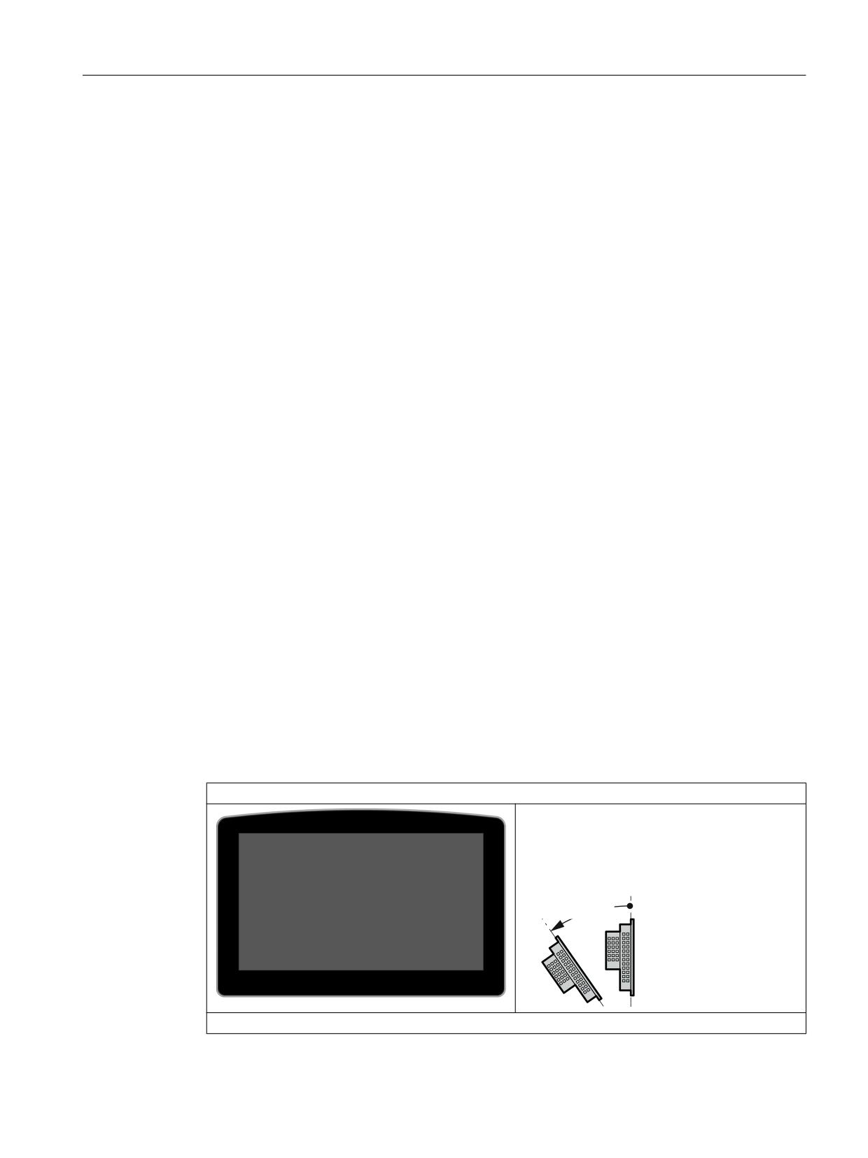
IFP2200 DMG MT OEM
● Robust aluminum front
● Integrated glass front, scratch-proof,
chemically resistant and anti-glare
● Inclination: Max. 35° to the rear
rದ r
IPC627D OEM
ERGOline Stage 3
Manual, 02/2018, 6FC5397-4FP40-0BA1
9
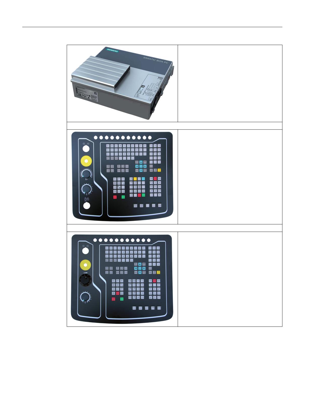
Description
2.3 Mechanical design
● Robust metal installation housing,
chromated, vibration and shock resistant,
with high level of EMC compatibility
● High level of data security through mirrored
disk system (RAID 1)
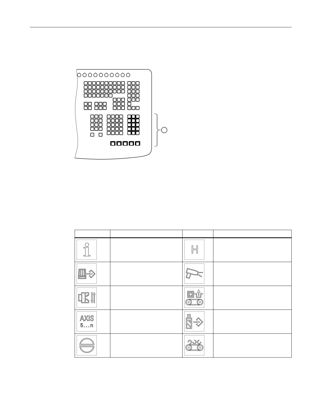
● CMOS backup battery externally accessible,
can be replaced during operation
MCP 466C-M IE (milling)
Stainless steel front with:
● CNC keyboard
● Machine control keys
●
2 x overrides
MCP 466C-T IE (turning)
Stainless steel front with:
● CNC keyboard
● Machine control keys
●
1 x override
●
1 x handwheel
ERGOline Stage 3
10
Manual, 02/2018, 6FC5397-4FP40-0BA1
Description
2.4 Key caps
2.4
Key caps
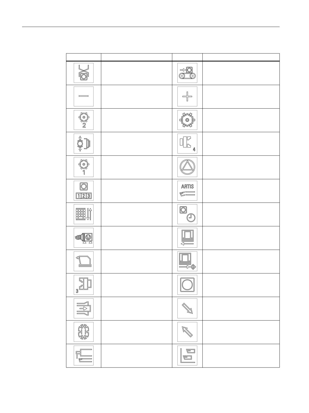
The machine control panels are delivered with exchangeable key caps ex factory.
Figure 2-1
Position of the exchangeable key caps ①
There are different key caps for the different technologies:
● MCP 466C-M IE (milling): 10 units
● MCP 466C-T IE (turning): 37 units (33 labeled, 4 not labeled)
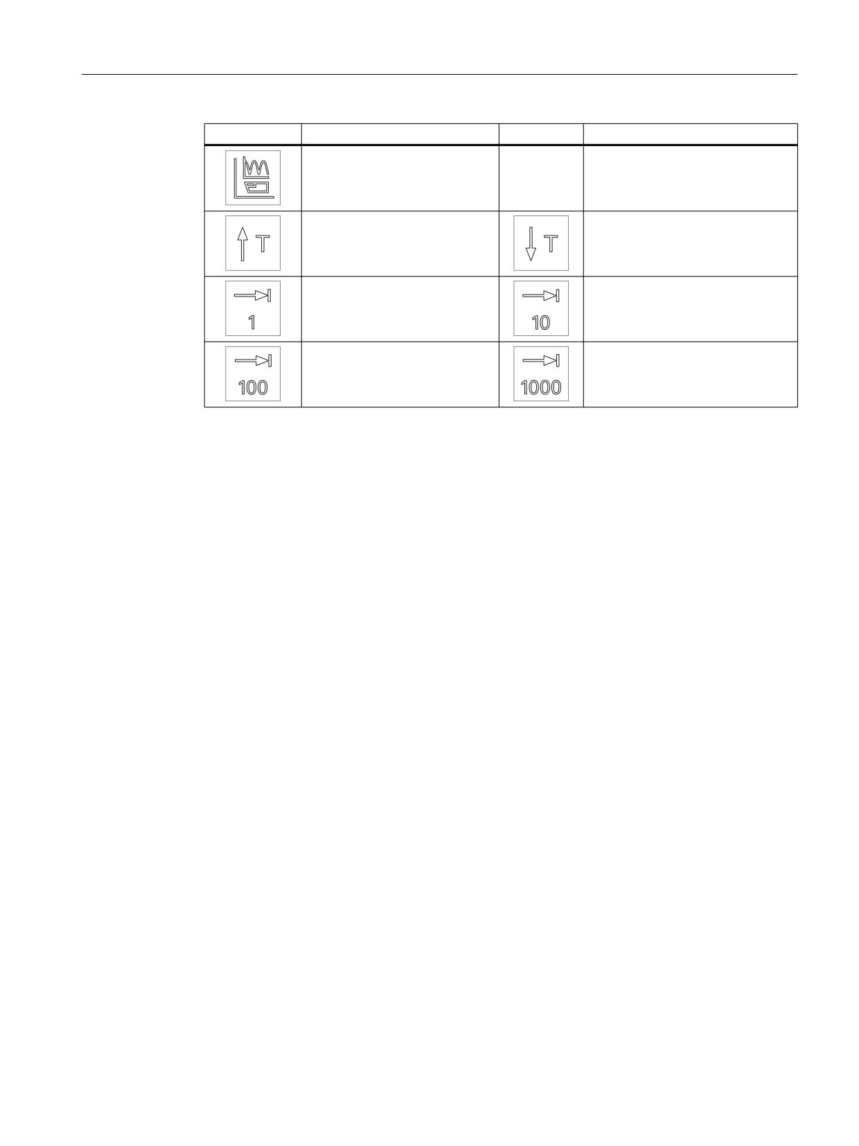
The printed symbols and their meaning are listed in the following tables depending on the
technology:
Table 2-1
Exchangeable key caps for the MCP 466C-M IE (milling)
Symbol
Meaning
Symbol
Meaning
Info
(7155)
(6035)
Spray gun
(7159)
(7156)
Chuck open/closed
Unlock door for workpiece
(7158)
conveyor (7162)
Axis switchover
(7154)
(7161)
Acknowledgement
Chip conveyor
(7157)
(7160)
ERGOline Stage 3
Manual, 02/2018, 6FC5397-4FP40-0BA1
11
Description
2.4 Key caps
Table 2-2
Exchangeable key caps for the MCP 466C-T IE (turning)
Symbol
Meaning
Symbol
Meaning
Pick-up
Conveyor belt
(7135)
(7138)
Minus
Plus
(7032)
(7033)
Turret_2
Turret
(7095)
(7092)
Spindle
Chuck_4
(7148)
(7147)
Turret_1
Teststop_Safety
(7094)
(7149)
Workpiece_counter
Tool_monitor_Artis
(7152)
(7136)
Control_switchover
Workpiece_time
(7137)
(7153)
Oil_trap
Open door
(7140)
(7163)
Tailstock
Close door
(7143)
(7164)
Chuck_3
(7146)
(7165)
Bar_feed
(7150)
(7166)
Workpiece_changer
(7093)
(7167)
Tool_monitor_Leukhardt
(7151)
(7168)
ERGOline Stage 3
12
Manual, 02/2018, 6FC5397-4FP40-0BA1
Description
2.4 Key caps
Symbol
Meaning
Symbol
Meaning
(7169)
(7170)
(7171)
(7010)
(7016)
(7019)
(7023)
ERGOline Stage 3
Manual, 02/2018, 6FC5397-4FP40-0BA1
13
Operator control and display elements
3
3.1
Monitor
The monitor is operated on the front exclusively via multitouch with the fingers or touch pen:
● Multitouch-capable; detection of up to five fingers simultaneously
● Intelligent operating error detection, e.g. ball of the hand detection, drop detection, pollution
● Operation with thin work gloves is possible
An external keyboard and mouse can also be connected to the rear via USB, see Section
Interfaces (Page 19).
3.2
Milling machine control panel
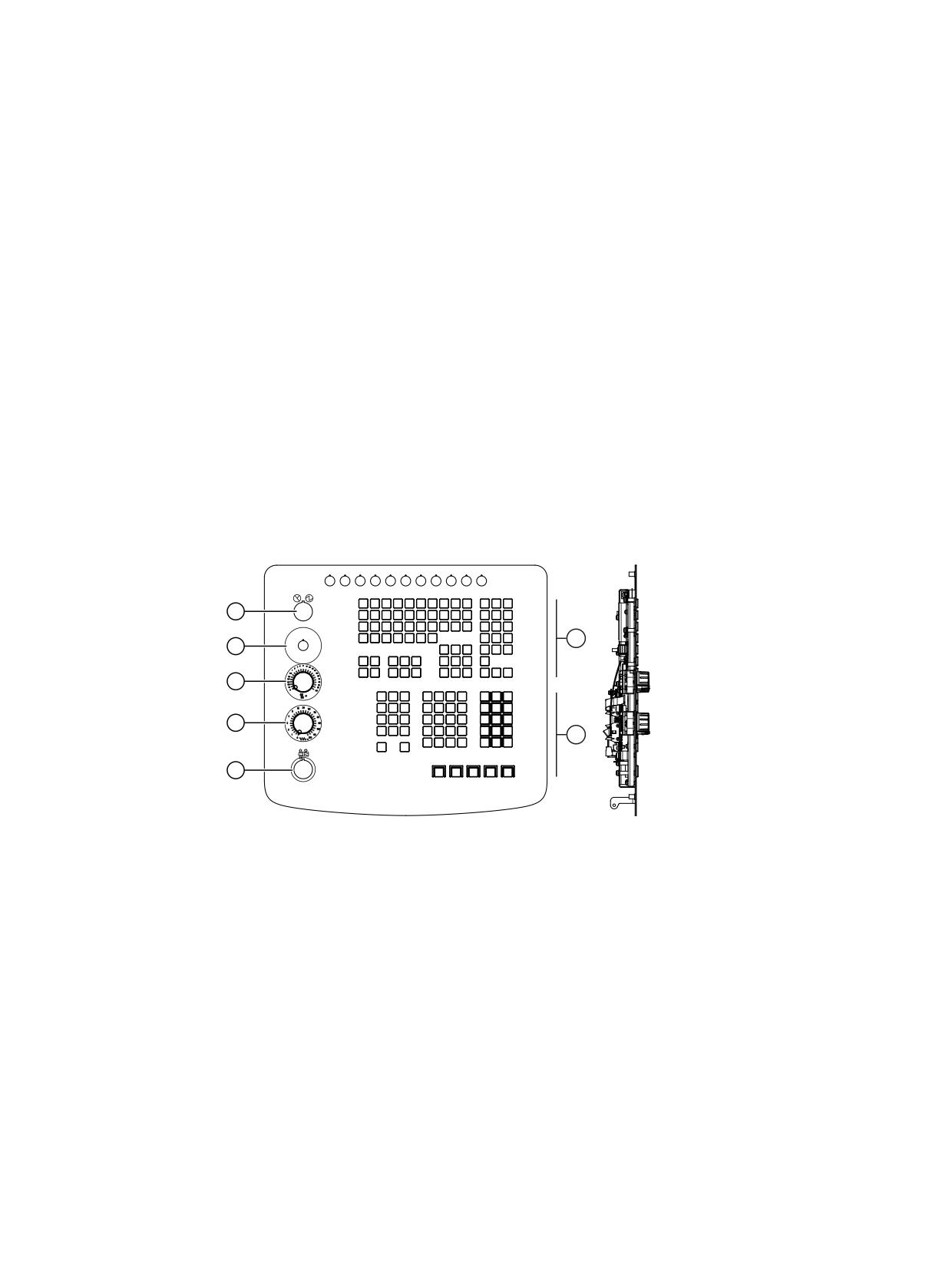
Operator control and display elements of the MCP 466C-M IE.
① CNC keyboard
② Machine control keys
③ Slot for "Clamp tool" illuminated key
④ Feedrate override rotary switch
⑤ Rapid traverse override rotary switch
⑥ Slot for emergency stop
⑦ Slot for "Machine ON" illuminated key
Figure 3-1
MCP 466C-M IE (front and side view)
ERGOline Stage 3
Manual, 02/2018, 6FC5397-4FP40-0BA1
15
Operator control and display elements
3.3 Turning machine control panel
CNC keyboard
● USB keyboard (without function keys)
● Operating area keys (hotkeys):
MACHINE, PROGRAM, OFFSET, PROGRAM MANAGER, ALARM and CUSTOM
● Further keys:
ALARM CANCEL, HELP, GROUP CHANNEL, INSERT, SELECT and NEXT WINDOW
Operator controls
●
54 keys
●
1 x feedrate override rotary switch (0-120%, 29 latched positions)
●
1 x rapid traverse override rotary switch (0-100%, 23 latched positions)
Options
Mounting option for:
●
1 x emergency stop button (16 mm system)
●
1 x "Machine ON" illuminated key (22 mm system)
●
1 x "Clamp tool" illuminated key (22 mm system)
3.3
Turning machine control panel
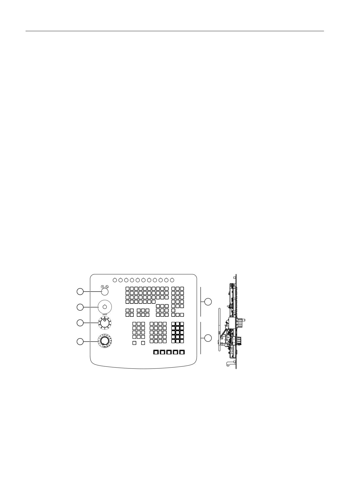
Operator control and display elements of the MCP 466C-T IE.
① CNC keyboard
② Machine control keys
③ Feedrate override rotary switch
④ Handwheel
⑤ Slot for emergency stop
⑥ Slot for "Machine ON" illuminated key
Figure 3-2
MCP 466C-T IE (front and side view)
ERGOline Stage 3
16
Manual, 02/2018, 6FC5397-4FP40-0BA1
Operator control and display elements
3.3 Turning machine control panel
CNC keyboard
● USB keyboard (without function keys)
● Operating area keys (hotkeys):
MACHINE, PROGRAM, OFFSET, PROGRAM MANAGER, ALARM and CUSTOM
● Further keys:
ALARM CANCEL, HELP, GROUP CHANNEL, INSERT, SELECT and NEXT WINDOW
Operator controls
●
54 keys
●
1 x feedrate override rotary switch (0-120%, 29 latched positions)
●
1 x handwheel (100 pulses/revolution, approx. 60 mm wheel diameter)
Options
Mounting option for:
●
1 x emergency stop button (16 mm system)
●
1 x "Machine ON" illuminated key (22 mm system)
ERGOline Stage 3
Manual, 02/2018, 6FC5397-4FP40-0BA1
17
Interfaces
4
4.1
Monitor
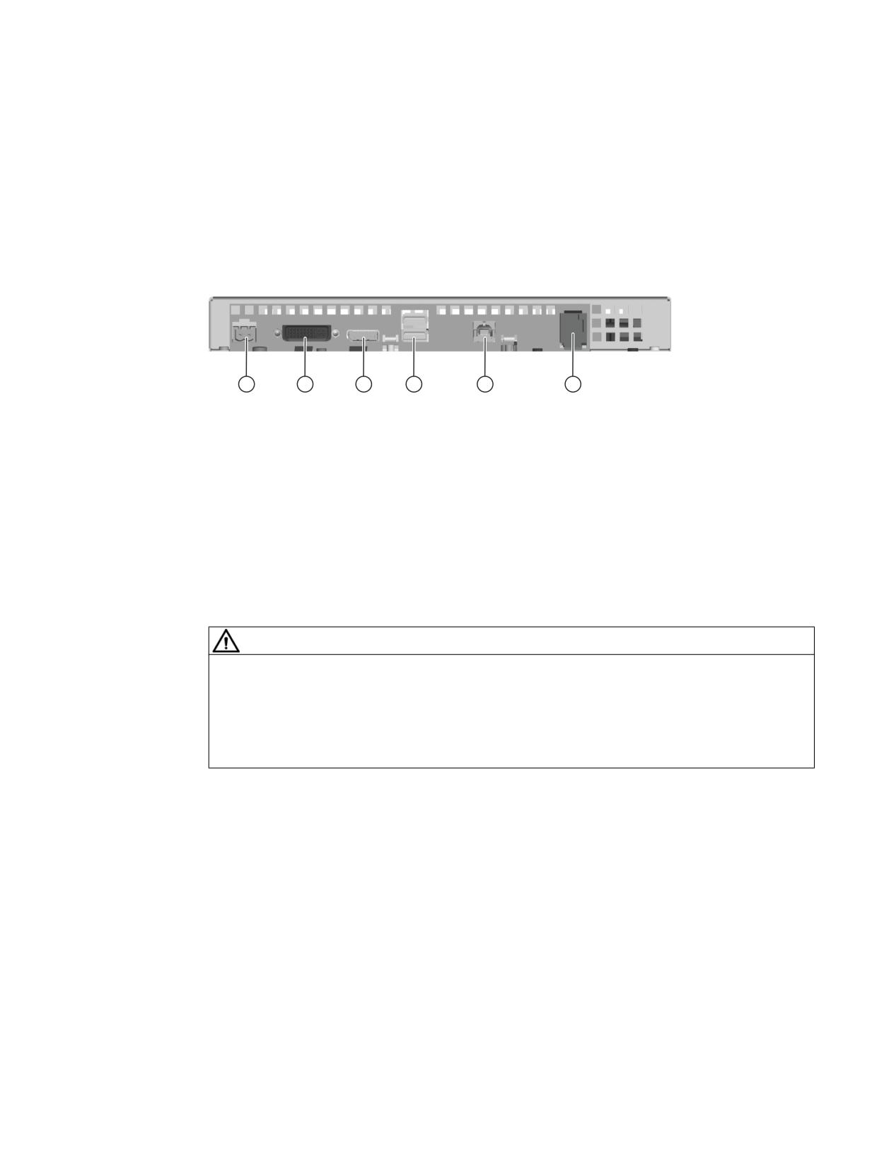
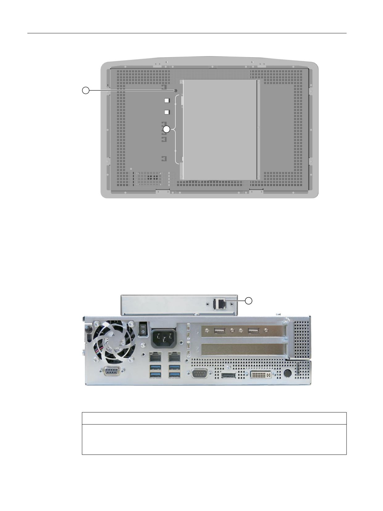
The figure below shows the interfaces of the device.
① X80 connection for the 24 VDC power sup- ④ X61/X62 USB type A
ply
② X71 DVI-D interface
⑤ X60 USB type B
③ X70 DisplayPort interface
⑥ X63 USB link interface (USB 2.0) - RJ45 socket
Pin assignment
You can find the pin assignment of the interfaces in the standard documentation, Section
"Technical specifications" → "Interface description".
Protective conductor connection
WARNING
Personal injury or property damage may occur with no ground connection
Inadequate or non-existent ground connection will cause malfunction of the capacitive touch
screen. This can result in personal injury or property damage.
Always connect the device to a protective conductor. The protective conductor must be
connected directly to ground with low impedance.
ERGOline Stage 3
Manual, 02/2018, 6FC5397-4FP40-0BA1
19
Interfaces
4.2 PC
① Protective conductor connection
② Position of the interfaces
Figure 4-1
Rear of SIMATIC IFP2200 MT OEM
4.2
PC
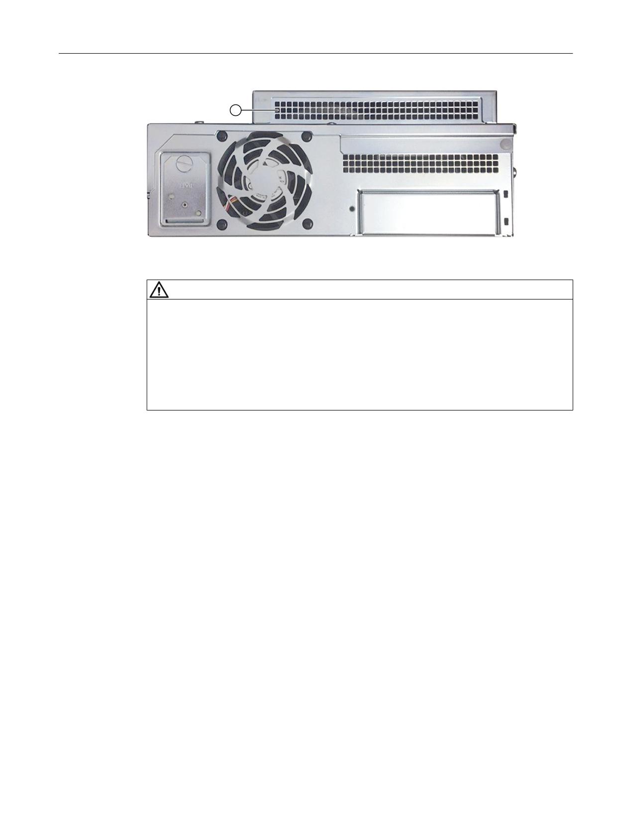
The device design corresponds to that of the SIMATIC IPC627D standard device
supplemented by an additional cover with an RJ45 socket for the connection of the USB link
cable.
① USB link interface
Figure 4-2
IPC627D DMG interfaces
NOTICE
No LAN/WAN connection
The RJ45 socket of the USB link interface is not an LAN/WAN connection and is only
approved for the connection of a SIMATIC IFP2200 MT OEM via CAT6 cable.
ERGOline Stage 3
20
Manual, 02/2018, 6FC5397-4FP40-0BA1
Interfaces
4.2 PC
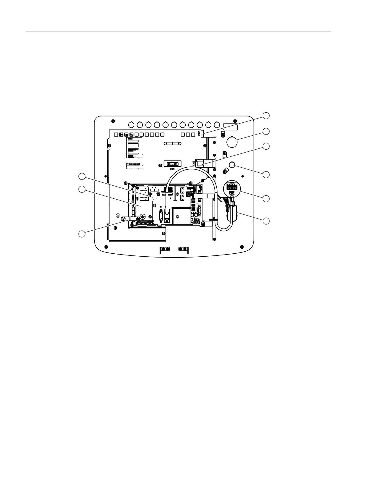
① Cover air outlet
Figure 4-3
IPC627D DMG rear view
WARNING
Internal front interfaces must not be used
The following internal front interfaces on the SIMATIC IPC627D OEM motherboard must not
be used:
● X570: Connection of LCD displays
● X571: Interface for I/O front
● X561: Internal USB 2.0 interface (USB channel 6)
● X560: Internal USB 3.0 interface (USB channel 3)
ERGOline Stage 3
Manual, 02/2018, 6FC5397-4FP40-0BA1
21
Interfaces
4.3 Machine control panels
4.3
Machine control panels
4.3.1
Overview
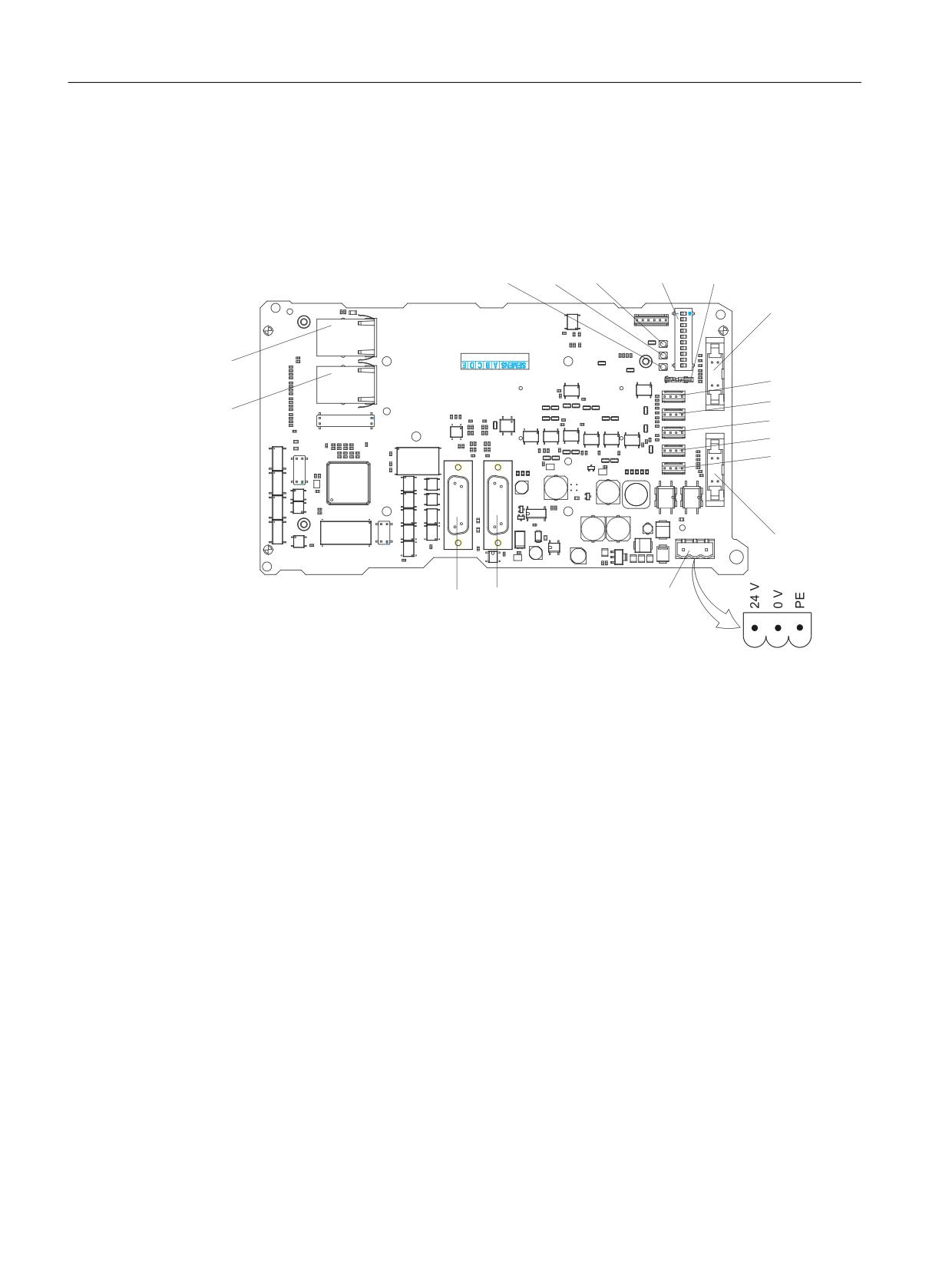
The position of the modules and interfaces is identical for both machine control panels.
① X302
USB-B (for connection of the CNC keyboard to the control panel)
②
Slot for illuminated key (not in the scope of delivery)
③ X303 A/B
2 x USB-A
④
Slot for emergency stop button (not in the scope of delivery)
⑤
Handwheel (rapid traverse override rotary switch for MCP 466C-M)
⑥
Feedrate override rotary switch
⑦
Grounding lug
⑧
Cover plate
⑨
COM board IE
Figure 4-4
MCP 466C-T IE machine control panel (turning)
Meaning of the abbreviations in the "Signal type" table column:
I
Input
O
Output
B
Bidirectional
V
Power supply
ERGOline Stage 3
22
Manual, 02/2018, 6FC5397-4FP40-0BA1

Interfaces
4.3 Machine control panels
X302
The X302 interface is designed as a "high powered interface" with max. 500 mA, 5 V. The
connection between the keyboard and operator panel is established via X302.
Connector designa-
X302; USB-B connector, 4-pin
tion:
Table 4-1
Assignment of connector X302
Pin
Signal name
Signal type
Meaning
1
P5
V
+ 5 V power supply
for external USB device
2
USB_DM0
Data -; channel 0
B
3
USB_DP0
Data +; channel 0
4
M
V
Ground
X303 A/B
These interfaces are used for the connection of simple USB extensions such as a USB mouse
or USB keyboard. They are designed as "low powered interface" with max. 100 mA, 5 V.
Connector designa-
X303 A/B; USB connector type A, 4-pin
tion:
Table 4-2
Assignment of connector X303 A
Pin
Signal name
Signal type
Meaning
A1
1P5
V
+ 5 V power supply
for external USB device
A2
USB_DM2
Data -; channel 2
B
A3
USB_DP2
Data +; channel 2
A4
M
V
Ground
Table 4-3
Assignment of connector X303 B
Pin
Signal name
Signal type
Meaning
B1
2P5
V
+ 5 V power supply
for external USB device
B2
USB_DM3
Data -; channel 3
B
B3
USB_DP3
Data +; channel 3
B4
M
V
Ground
ERGOline Stage 3
Manual, 02/2018, 6FC5397-4FP40-0BA1
23
Interfaces
4.3 Machine control panels
4.3.2
COM board IE MCP
Overview
The figure shows the position of the interfaces on the COM board of the machine control panels.
+
+
+
6
6
;
;
;
;
;
;
;
;
;
;
;
;
X10
24 V power supply
X20/X21
Ethernet ports
X30
Interface for feedrate override rotary switch
X31
Interface for rapid traverse override rotary switch
X51/X52
Customer keys, inputs for illuminated keys
X53/X54
Customer keys, outputs for illuminated keys
X55
Customer key, input
X60/X61
Connections for two handwheels
S1
Handwheel change-over switch: Differential/TTL
S2
DIP switches: MCP address
H1 to H3
Status LEDs
Figure 4-5
COM board IE MCP (shown without cover plate and grounding lug)
Signal types
Meaning of the abbreviations in the "Signal type" table column for the pin assignment of the
individual components:
I
Input
O
Output
ERGOline Stage 3
24
Manual, 02/2018, 6FC5397-4FP40-0BA1

Interfaces
4.3 Machine control panels
B
Bidirectional
V
Power supply
X10 power supply
Connector designa-
X10; 3-pin terminal block
tion:
Table 4-4
Assignment of connector X10
Pin
Signal name
Signal type
Meaning
1
P24
24 V potential
2
M24
Ground 24 V
V
3
SHIELD
Shield connection
Ethernet X20/X21
Connector designation:
X20, X21
Connector type:
RJ45 socket
Table 4-5
Assignment of connectors X20, X21
Pin
Name
Type
Meaning
1
TX+
I
Transmit +
2
TX-
I
Transmit -
3
RX+
O
Receive +
4
N.C.
-
Not assigned
5
N.C.
-
Not assigned
6
RX-
O
Receive -
7
N.C.
-
Not assigned
8
N.C.
-
Not assigned
Feedrate override rotary switch X30
Connector designation:
X30
Connector type:
2 x 5-pin male connectors, acc. to IEC603-13 with coding
Table 4-6
Assignment of connector X30
Pin
Name
Type
Meaning
1
N.C.
-
Not assigned
2
N.C.
-
Not assigned
ERGOline Stage 3
Manual, 02/2018, 6FC5397-4FP40-0BA1
25

Interfaces
4.3 Machine control panels
Pin
Name
Type
Meaning
3
M
V
Ground
4
N.C.
-
Not assigned
5
P5
V
5 V supply
6
OV_VS16
Override rotary switch, position/value 16
7
OV_VS8
Override rotary switch, position/value 8
8
OV_VS4
I
Override rotary switch, position/value 4
9
OV_VS2
Override rotary switch, position/value 2
10
OV_VS1
Override rotary switch, position/value 1
Rapid traverse override rotary switch X31
Connector designation:
X31
Connector type:
2 x 5-pin male connectors, acc. to IEC603-13 with coding
Table 4-7
Assignment of connector X31
Pin
Name
Type
Meaning
1
N.C.
-
Not assigned
2
N.C.
-
Not assigned
3
M
V
Ground
4
N.C.
-
Not assigned
5
P5
V
5 V supply
6
OV_EG16
Override rotary switch, position/value 16
7
OV_ EG8
Override rotary switch, position/value 8
8
OV_ EG4
I
Override rotary switch, position/value 4
9
OV_ EG2
Override rotary switch, position/value 2
10
OV_ EG1
Override rotary switch, position/value 1
Optional customer keys X51/X52/X55
Only switches (passive inputs) may be connected via the X51, X52 and X55 connectors.
X51 and X52 are usually intended for connecting illuminated pushbuttons.
The lamps in the buttons are activated via X53 and X54. X55 has no corresponding output.
ERGOline Stage 3
26
Manual, 02/2018, 6FC5397-4FP40-0BA1
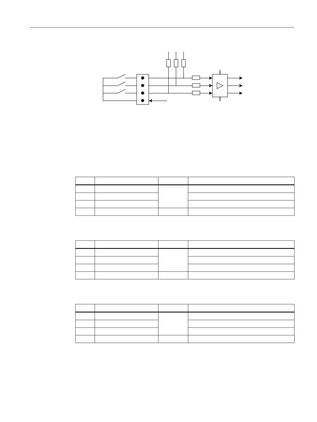
Interfaces
4.3 Machine control panels
9
9
; L
.7M ,1
.7M ,1
.7M ,1
0
0
L
M
Figure 4-6
Schematic circuit diagram of the input circuit for X51 and X52
Interface:
Optional customer keys IN
Connector designation:
X51 / X52 / X55
Connector type:
4-pin male connector
Table 4-8
Assignment of connector X51
Pin
Name
Type
Meaning
1
KT-IN1
Customer key 1
2
KT-IN2
I
Customer key 2
3
KT-IN3
Customer key 3
4
M
V
Ground
Table 4-9
Assignment of connector X52
Pin
Name
Type
Meaning
1
KT-IN4
Customer key 4
2
KT-IN5
I
Customer key 5
3
KT-IN6
Customer key 6
4
M
V
Ground
Table 4-10
Assignment of connector X55
Pin
Name
Type
Meaning
1
KT-IN7
Customer key 7
2
KT-IN8
I
Customer key 8
3
KT-IN9
Customer key 9
4
M
V
Ground
ERGOline Stage 3
Manual, 02/2018, 6FC5397-4FP40-0BA1
27
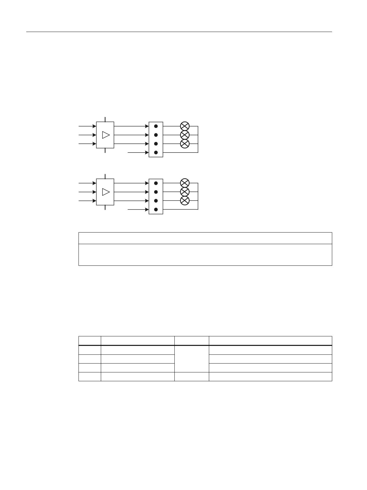
Interfaces
4.3 Machine control panels
Optional customer keys X53/X54
The outputs X53 / X54 are intended to activate lamps in the keys.
We would recommend using 1.2 W lamps with max. 0.3 A per output.
High-side switches which switch 24 V to the lamps and limit the current during short circuits
are used as output drivers.
+LJK 6LGH 6ZLWFK
3
;
.7 287
.7 287
.7 287
0
0
3
;
.7 287
.7 287
.7 287
0
0
Figure 4-7
Schematic circuit diagram of the output circuit for X53 and X54
NOTICE
Damage to the module through induction voltages
Do not connect any relays, valves or other inductive loads.
Interface:
Optional customer keys OUT
Connector designation:
X53/X54
Connector type:
4-pin male connector
Table 4-11
Assignment of connector X53
Pin
Name
Type
Meaning
1
KT-OUT1
Customer key 1 lamp
2
KT-OUT2
O
Customer key 2 lamp
3
KT-OUT3
Customer key 3 lamp
4
M
V
Ground
ERGOline Stage 3
28
Manual, 02/2018, 6FC5397-4FP40-0BA1

Interfaces
4.3 Machine control panels
Table 4-12
Assignment of connector X54
Pin
Name
Type
Meaning
1
KT-OUT4
Customer key 4 lamp
2
KT-OUT5
O
Customer key 5 lamp
3
KT-OUT6
Customer key 6 lamp
4
M
V
Ground
Handwheels X60/X61
Interface:
Handwheels
Connector designation:
X60/X61
Connector type:
15-pin Sub-D socket
Table 4-13
Assignment of connector X60
Pin
Name
Type
Meaning
1
P5HW
V
Supply voltage 5V
2
M
V
Ground
3
HW1_A
I
Handwheel pulses track A
4
HW1_XA
I
Handwheel pulses track A (negated)
5
N.C.
-
Not assigned
6
HW1_B
I
Handwheel pulses track B
7
HW1_XB
I
Handwheel pulses track B (negated)
8
N.C.
-
Not assigned
9
P5HW
V
5V power supply
10
N.C.
-
Not assigned
11
M
V
Ground
12
N.C.
-
Not assigned
13
N.C.
-
Not assigned
14
N.C.
-
Not assigned
15
N.C.
-
Not assigned
Table 4-14
Assignment of connector X61
Pin
Name
Type
Meaning
1
P5HW
V
Supply voltage 5V
2
M
V
Ground
3
HW2_A
I
Handwheel pulses track A
4
HW2_XA
I
Handwheel pulses track A (negated)
5
N.C.
-
Not assigned
6
HW2_B
I
Handwheel pulses track B
7
HW2_XB
I
Handwheel pulses track B (negated)
ERGOline Stage 3
Manual, 02/2018, 6FC5397-4FP40-0BA1
29

Interfaces
4.3 Machine control panels
Pin
Name
Type
Meaning
8
N.C.-
-
Not assigned
9
P5HW
V
5V power supply
10
N.C.
-
Not assigned
11
M
V
Ground
12
N.C.
-
Not assigned
13
N.C.
-
Not assigned
14
N.C.
-
Not assigned
15
N.C.
-
Not assigned
Status LEDs
Table 4-15
Meaning of the status LEDs
No.
Color
Meaning
H1
Green
Power OK
H2
Green
PROFINET LED (BUS SYNC)
H3
Red
PROFINET LED (BUS FAULT)
DIP switch S1
Setting the handwheel signal type
- S1 open: TTL
- S1 closed: Differential interface
Switch S2
Table 4-16
Switch S2 setting as delivered
1
2
3
4
5
6
7
8
9
10
Meaning
off
off
off
off
off
off
off
off
on
on
MCP address 192
The two switches S2-9 and S2-10 must remain OFF.
The switches S2-1 to S2-8 define the MCP address in the range of 0 to 255.
The addresses from 192 to 223 count as the default range.
The MCP address is used as a reference for addressing an MCP during PLC parameter
assignment.
Table 4-17
Settings of switch S2
1
2
3
4
5
6
7
8
9
10
Meaning
off
off
on
on
on
on
on
on
on
on
MCP address 255
x
x
x
x
x
x
x
x
"
ERGOline Stage 3
30
Manual, 02/2018, 6FC5397-4FP40-0BA1

Interfaces
4.3 Machine control panels
1
2
3
4
5
6
7
8
9
10
Meaning
on
on
on
on
on
off
on
on
MCP address 223
off
on
on
on
on
off
on
on
MCP address 222
on
off
on
on
on
off
on
on
MCP address 221
off
off
on
on
on
off
on
on
MCP address 220
on
on
off
on
on
off
on
on
MCP address 219
off
on
off
on
on
off
on
on
MCP address 218
on
off
off
on
on
off
on
on
MCP address 217
off
off
off
on
on
off
on
on
MCP address 216
on
on
on
off
on
off
on
on
MCP address 215
off
on
on
off
on
off
on
on
MCP address 214
on
off
on
off
on
off
on
on
MCP address 213
off
off
on
off
on
off
on
on
MCP address 212
on
on
off
off
on
off
on
on
MCP address 211
off
on
off
off
on
off
on
on
MCP address 210
on
off
off
off
on
off
on
on
MCP address 209
off
off
off
off
on
off
on
on
MCP address 208
on
on
on
on
off
off
on
on
MCP address 207
off
on
on
on
off
off
on
on
MCP address 206
on
off
on
on
off
off
on
on
MCP address 205
off
off
on
on
off
off
on
on
MCP address 204
on
on
off
on
off
off
on
on
MCP address 203
off
on
off
on
off
off
on
on
MCP address 202
on
off
off
on
off
off
on
on
MCP address 201
off
off
off
on
off
off
on
on
MCP address 200
on
on
on
off
off
off
on
on
MCP address 199
off
on
on
off
off
off
on
on
MCP address 198
on
off
on
off
off
off
on
on
MCP address 197
off
off
on
off
off
off
on
on
MCP address 196
on
on
off
off
off
off
on
on
MCP address 195
off
on
off
off
off
off
on
on
MCP address 194
on
off
off
off
off
off
on
on
MCP address 193
off
off
off
off
off
off
on
on
MCP address 192
x
x
x
x
x
x
x
x
"
on
off
off
off
off
off
off
off
MCP address 001
off
off
off
off
off
off
off
off
MCP address 000
ERGOline Stage 3
Manual, 02/2018, 6FC5397-4FP40-0BA1
31

Interfaces
4.3 Machine control panels
4.3.3
Input/output images
Input image for milling
Byte
Bit7
Bit6
Bit5
Bit4
Bit3
Bit2
Bit1
Bit0
IB 0
1) Cycle
Spindle
Spindle
Spindle
Single
JOG
MDA
AUTO
stop
inc
100%
dec
block
IB 1
Cycle
Spindle
1) Spindle
Spindle
DMG1
REF
REPOS
Teach
start
right
stop
left
POINT
in
IB 2
Feed
1) Feed
INC
DMG2
INC
INC
INC
INC
start
stop
var
1000
100
10
1
IB 3
RESET
DMG3
DMG4
1) OV_VS16
1) OV_VS8
1) OV_VS4
1) OV_VS2
1) OV_VS1
IB 4
+
-
RAPID
DMG5
DMG6
DMG7
⇗
DMG8
IB 5
DMG9
DMG10
DMG11
DMG12
Cursor
Cursor
Cursor
Cursor
up
down
right
left
IB 6
DMG13
⇙
DMG14
DMG15
Offset
DMG16
DMG17
DMG18
IB 7
DMG19
DMG20
DMG21
1) OV_EG16
1) OV_EG8
1) OV_EG4
1) OV_EG2
1) OV_EG1
IB 8 2)
DT 8
DT 7
DT 6
DT 5
DT 4
DT 3
DT 2
DT 1
IB 9 2)
DT 16
DT 15
DT 14
DT 13
DT 12
DT 11
DT 10
DT 9
IB 10
KT 8
KT 7
KT 6
KT 5
KT 4
KT 3
KT 2
KT 1
IB 11 3)
SS-3(24)
SS-2(22)
SS-1(14)
SS-0(12)
-
-
-
KT 9
IB 12
-
-
-
-
-
-
-
-
IB 13
-
-
-
-
-
-
-
-
1) Inverse signals
2) DT1 to DT16 - direct keys
3) Keyswitch X50
Input image for turning
Byte
Bit7
Bit6
Bit5
Bit4
Bit3
Bit2
Bit1
Bit0
IB 0
1) Cycle
P8
P7
Spindle
Spindle
JOG
MDA
AUTO
stop
100%
block
IB 1
Cycle
Spindle
1) Spindle
Spindle
DMG2
REF
REPOS
Teach
start
right
stop
left
POINT
in
IB 2
P10
1) P9
DMG1
P1
DMG9
DMG8
DMG5
DMG3
IB 3
Feed
P2
P0
1) OV_VS16
1) OV_VS8
1) OV_VS4
1) OV_VS2
1) OV_VS1
stop
IB 4
B
⇙
Cursor
P3
P4
Cursor
Cursor
RESET
right
up
left
right
IB 5
Feed
DMG6
P5
P6
DMG4
Rapid
⇗
B
100%
left
IB 6
DMG7
Cursor
Cursor
DMG10
Offset
Cursor
M01
SKP
left
right
down
IB 7
SKP7
DMG11
DMG12
1) Override
1) Override
1) Override
1) Override
1) Override
spindle16
spindle8
spindle4
spindle2
spindle1
ERGOline Stage 3
32
Manual, 02/2018, 6FC5397-4FP40-0BA1
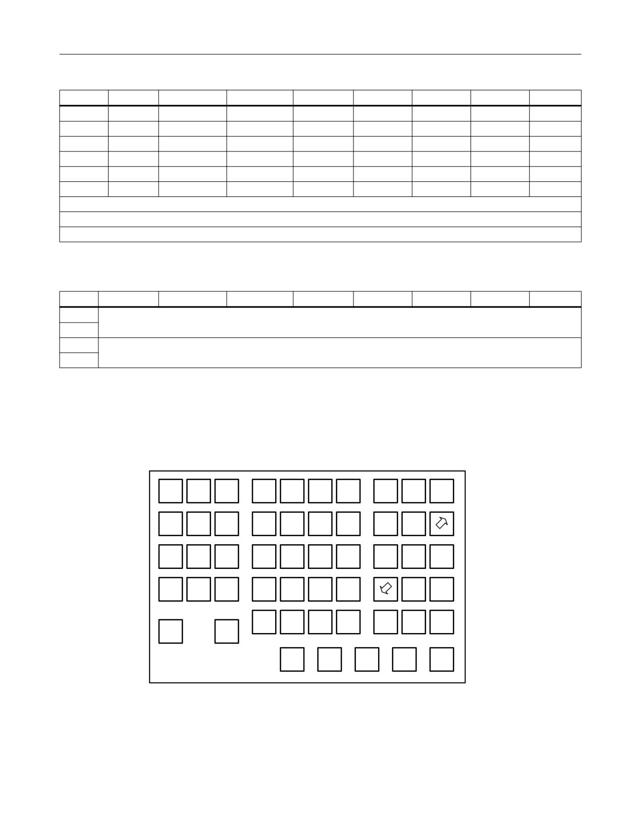
Interfaces
4.3 Machine control panels
Byte
Bit7
Bit6
Bit5
Bit4
Bit3
Bit2
Bit1
Bit0
IB 8 2)
DT 8
DT 7
DT 6
DT 5
DT 4
DT 3
DT 2
DT 1
IB 9 2)
DT 16
DT 15
DT 14
DT 13
DT 12
DT 11
DT 10
DT 9
IB 10
KT-IN8
KT-IN7
KT-IN6
KT-IN5
KT-IN4
KT-IN3
KT-IN2
KT-IN1
IB 11 3)
SS-3(24)
SS-2(22)
SS-1(14)
SS-0(12)
-
-
-
KT-IN9
IB 12
-
-
-
-
-
-
-
-
IB 13
-
-
-
-
-
-
-
-
1) Inverse signals
2) DT1 to DT16 - direct keys
3) Keyswitch X50
Table 4-18
Input image for handwheel data
Byte
Bit7
Bit6
Bit5
Bit4
Bit3
Bit2
Bit1
Bit0
IB 14
Handwheel 1 counter status
IB 15
(16-bit signed, least significant byte equals byte n+14)
IB 16
Handwheel 2 counter status
IB 17
(16-bit signed, least significant byte equals byte n+16)
Within the SINUMERIK control, the handwheel data is processed directly by the NCK and is
not available to the PLC.
Default key assignments
The DMG customer keys are not labeled.
5()
,1&
'0*
'0*
'0*
6SLQGOH
6SLQGOH
6SLQGOH
-2*
5(326
32,17
9$5
OHIW
6WRS
ULJKW
,1&
'0*
'0*
'0*
'0*
&XUVRU
0'$
7($&+
2IIVHW
,1
XS
'0*
'0*
,1&
'0*
'0*
'0*
&XUVRU
5DSLG
&XUVRU
$872
OHIW
ULJKW
6,1*/(
'0*
,1&
6SLQGOH
6SLQGOH
6SLQGOH
&XUVRU
'0*
5(6(7
%/2&.
'HF
LQF
GRZQ
,1&
'0*
)(('
)(('
'0*
6723
67$57
&<&/(
&<&/(
6723
67$57
'0*
'0*
'0*
'0*
'0*
,QYHUVH VLJQDOV
LQYHUVH LQSXWV
Figure 4-8
Milling key assignment
ERGOline Stage 3
Manual, 02/2018, 6FC5397-4FP40-0BA1
33
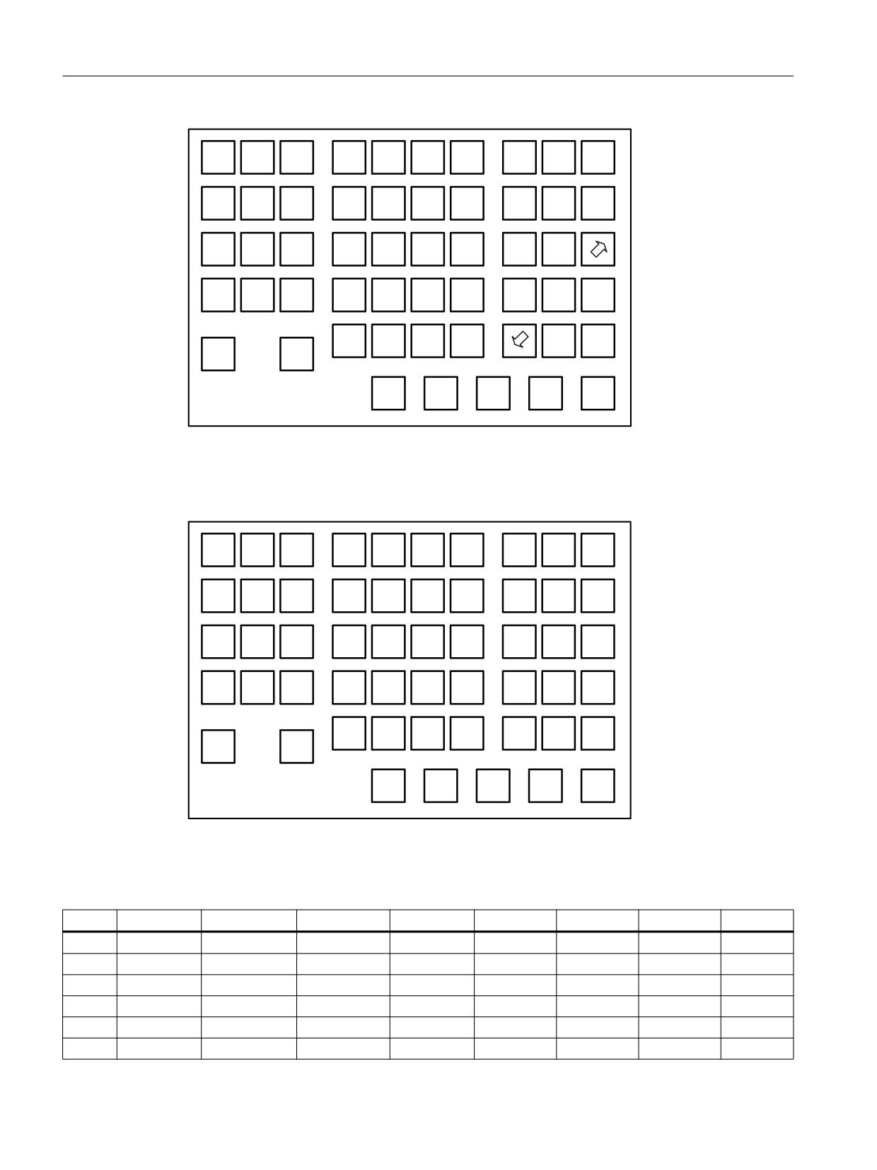
Interfaces
4.3 Machine control panels
5()
'0*
'0*
6SLQGOH
6SLQGOH
6SLQGOH
-2*
5(326
3
3
32,17
OHIW
6WRS
ULJKW
'0*
&
'0*
&
0'$
7($&+
2IIVHW
3
3
3
,1
OHIW
ULJKW
5HVHW
)(('
'0*
'0*
%
&XUVRU
$872
3
3
OHIW
XS
6,1*/(
)(('
'0*
'0*
6SLQGOH
&XUVRU
5DSLG
&XUVRU
3
3
%/2&.
6723
OHIW
ULJKW
'0*
'0*
&XUVRU
%
3
3
GRZQ
ULJKW
&<&/(
&<&/(
6723
67$57
6.3
'0*
'0*
0
6.3
,QYHUVH VLJQDOV
LQYHUVH LQSXWV
Figure 4-9
Turning key assignment
Assignment of the inputs to the keys
(
(
(
(
(
(
(
(
(
(
(
(
(
(
(
(
(
(
(
(
(
(
(
(
(
(
(
(
(
(
(
(
(
(
(
(
(
(
(
(
(
(
(
(
(
(
(
(
(
(
(
(
(
(
Figure 4-10
Keyboard layout
Output image
Byte
Bit7
Bit6
Bit5
Bit4
Bit3
Bit2
Bit1
Bit0
QB 0
-
-
-
-
-
-
-
-
QB 1
-
-
-
-
-
-
-
-
QB 2
-
-
-
-
-
-
-
-
QB 3
-
-
-
-
-
-
-
-
QB 4
-
-
-
-
-
-
-
-
QB 5
-
-
-
-
-
-
-
-
ERGOline Stage 3
34
Manual, 02/2018, 6FC5397-4FP40-0BA1
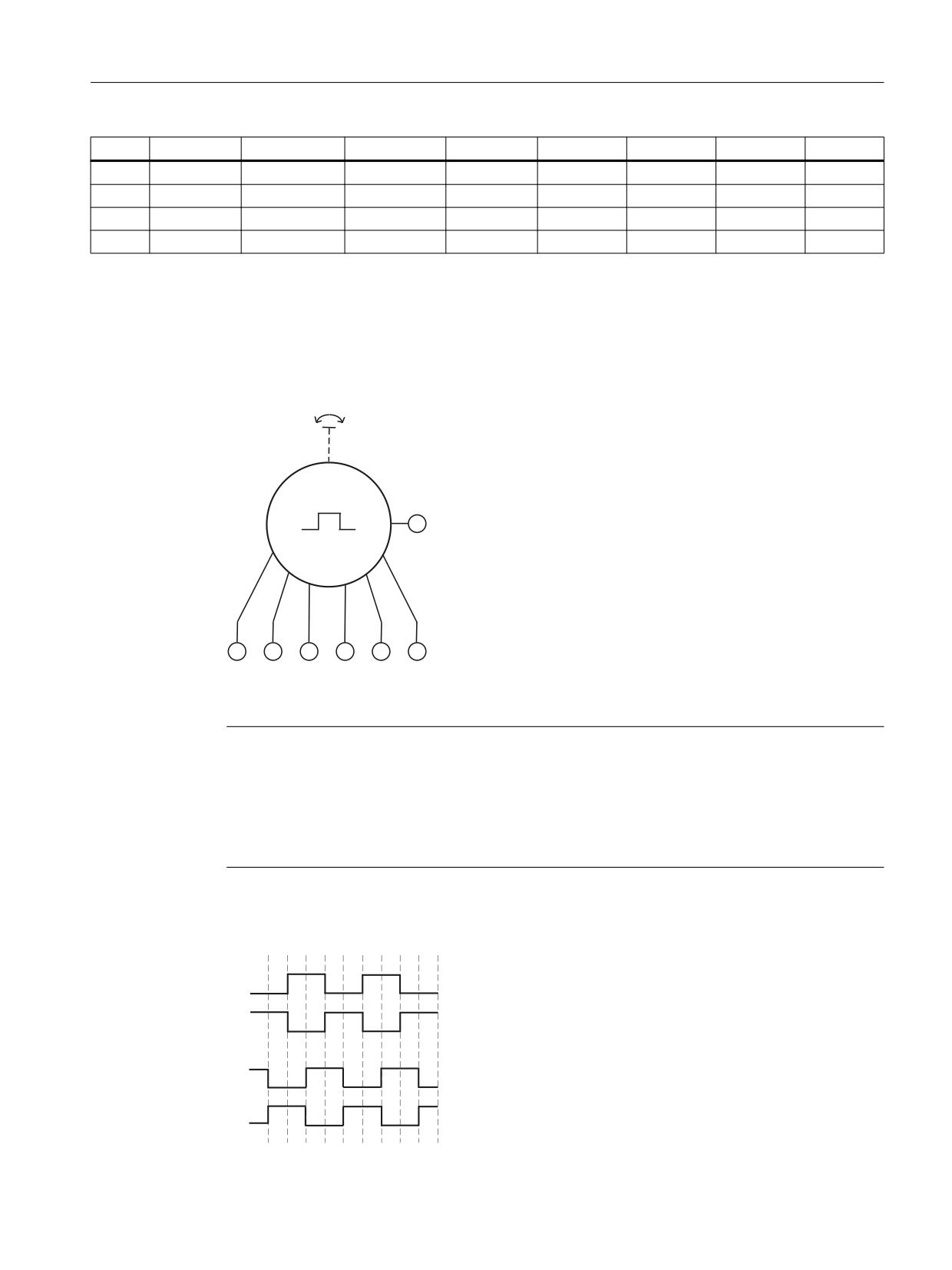
Interfaces
4.3 Machine control panels
Byte
Bit7
Bit6
Bit5
Bit4
Bit3
Bit2
Bit1
Bit0
QB 6
-
-
-
-
-
-
-
-
QB 7
-
-
-
-
-
-
-
-
QB 8
-
-
-
-
-
-
-
-
QB 9
-
-
KT-OUT6
KT-OUT5
KT-OUT4
KT-OUT3
KT-OUT2
KT-OUT1
4.3.4
Circuit diagrams
Handwheel (MCP 466C-T IE)
6KLHOG
9
9
$
$
%
%
Figure 4-11
Handwheel block diagram
Note
When a connected handwheel triggers pulses from its idle position or in the event of tiny
contacts, connect it so that the label is facing the wrong way.
Exchange
- The wire of terminal A with the wire of terminal /A
- The wire of terminal B with the wire of terminal /B
1
1
1
$
$
%
%
ERGOline Stage 3
Manual, 02/2018, 6FC5397-4FP40-0BA1
35
Interfaces
4.3 Machine control panels
Figure 4-12
Handwheel pulse diagram
ERGOline Stage 3
36
Manual, 02/2018, 6FC5397-4FP40-0BA1
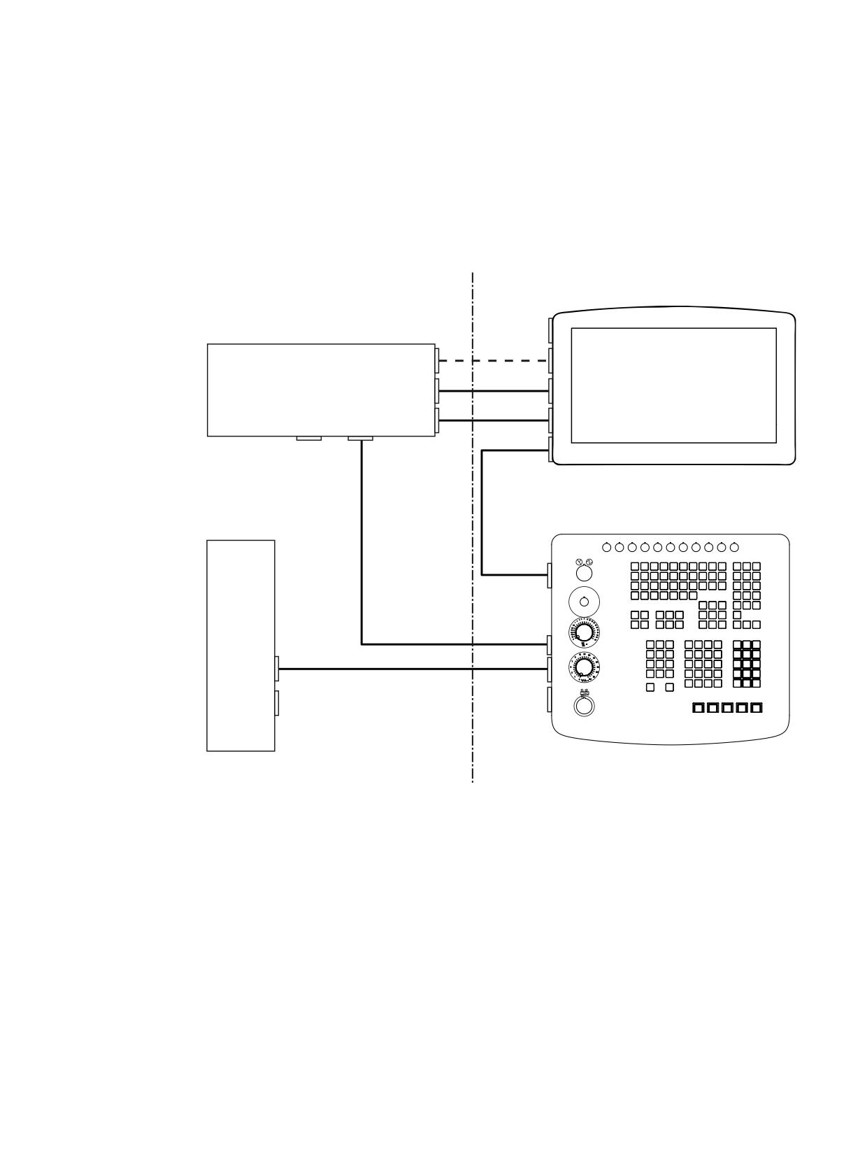
Connection
5
The following system configuration is suitable for the communication between the individual
components:
;
9
;
;
0RQLWRU
'9, '
,3&
;
;
'LVSOD\3RUW
;
86%
/LQN
9
;
;
;
86% 7\S $
0DFKLQH FRQWURO SDQHO
;
86% %
(WKHUQHW
;
1&8
;
(WKHUQHW
;
;
;
9
9
&RQWURO FDELQHW
2SHUDWRU SDQHO
Figure 5-1
System configuration for ERGOline stage 3
ERGOline Stage 3
Manual, 02/2018, 6FC5397-4FP40-0BA1
37
Connection
USB cables
● For the connection of:
- CNC keyboard of the MCP (X302) to the monitor (X61/X62).
- External USB devices, such as the mouse or keyboard, to the PC or the monitor.
Max. cable length: 3 m
● Signal cable (USB link) for the connection of the monitor (X63/X60) to the PC.
- Connection to X63 (RJ45 socket): Max. cable length: 30 m
Note
● A CAT6 cable is required. A ferrite core must be attached to each end of the cable
close to the connector. The two ferrite cores are included in the IFP and IPC scope
of delivery.
● Use the supplied strain relief clamps and cable ties for the cable grip of the USB link
cable at the IPC end. Use a TORX T10 screwdriver for this.
● The USB link is a pure hardware solution and therefore independent of the operating
system. An additional driver or software does not have to be installed.
- Connection to X60 with USB type B standard cable: Max. cable length: 5 m
Display cable
Connection between the monitor (X70/X71) and the PC (X70/X72).
Max. cable length: 30 m
Ethernet cables
● Connection between the MCP (X20) and the NCU (X120).
● Connection between the PC (X1) and the MCP (X21).
This cable must be ordered separately. Recommendations:
- Industrial Ethernet FastConnect cable
- Industrial Ethernet FastConnect connectors
The corresponding order numbers can be found in Section Accessories (Page 49).
Max. cable length: 100 m
NOTICE
Chafing edges can damage cables
Make sure that all cables are routed so that they do not come into contact with chafing edges.
ERGOline Stage 3
38
Manual, 02/2018, 6FC5397-4FP40-0BA1
Operating
6
Touch screen
The monitor has a touch screen with multitouch function. You operate this touch screen with
gestures that are executed with the fingertips on the touch screen. The gestures can be
executed with several fingers simultaneously.
WARNING
Faulty execution of gestures on the touch screen with multitouch function
If gestures are executed incorrectly on the touch screen with multitouch function, these
gestures may not be recognized or could be recognized incorrectly. The entries made are
then not implemented by the device or are implemented incorrectly or in an unintended
manner.
Note the following when operating the touch screen with multitouch function:
● The touch screen reacts to touches on its surface, not to pressure.
● When using a touch pen: Operate the touch screen only with a touch pen for capacitive
touch.
● When operating with your fingers: Only operate the touch screen with your finger tips, not
with the finger nails.
● Do not use thick gloves, such as working gloves, to operate the touch screen. You may
use thin cotton gloves or gloves intended for touch screens with capacitive touch.
● Touch the touch screen vertically and not obliquely to the surface.
● Avoid unintentional multiple touches, e.g. with the knuckles or by leaning against or on
the display.
● Make sure that the touch screen is kept free of dirt. You can find information on cleaning
on the Internet in the following article: What are the chemical resistances of the SIMATIC
HMI operating devices and Industrial PCs? (https://support.industry.siemens.com/cs/
#document/39718396?lc=en-WW).
Always check whether the executed operator actions were recognized by the device.
Setting the display brightness and screen saver
Set the display brightness and screen saver with the panel tools of the IPC wizard. Information
can be found in the IPC Wizard Manual on the "Documentation and Drivers" DVD.
ERGOline Stage 3
Manual, 02/2018, 6FC5397-4FP40-0BA1
39
Operating
ERGOline Stage 3
40
Manual, 02/2018, 6FC5397-4FP40-0BA1

Technical specifications
7
7.1
Monitor
7.1.1
Technical specifications
Table 7-1
SIMATIC IFP2200 MT OEM
Safety
Degree of protection according to DIN EN
I
61140
Degree of protection according to DIN EN
Front IP65
60529
Rear IP20
Approvals
CE / UL
Electrical data
Input voltage
24 VDC
Mechanical data
Dimensions (WxHxD)
560 × 365 × 63 mm
Display
Size
22" widescreen
Resolution
1920 x 1080 pixels at 16 million colors
7.1.2
Transport and Storage Conditions
Mechanical and climatic transport and storage conditions
With regard to transport and storage conditions, this device surpasses the requirements
according to DIN EN 60721-3-2. The following specification apply for a device that is
transported and stored in the original packaging.
Type of condition
Permissible range
Free fall (in transport packaging)
≤ 1 m
Temperature
-20 … +60° C
Atmospheric pressure
1080 ... 660 hPa, corresponds to an altitude of -1000 ... 3500
m
Relative humidity
10 ... 90%, without condensation
Sinusoidal vibration according to DIN EN 60068-6-2
5 … 8.4 Hz, deflection 3.5 mm
8.4 … 500 Hz, acceleration 1 g
Shock according to DIN EN 60068-2-27
25 g, 6 ms, 1000 shocks
ERGOline Stage 3
Manual, 02/2018, 6FC5397-4FP40-0BA1
41

Technical specifications
7.1 Monitor
The fault-free and safe operation of the device requires correct transport, storage, installation
and assembly, as well as careful operation and maintenance.
The warranty for the device is void if these regulations are not complied with.
7.1.3
Operating conditions
Mechanical and climatic conditions of use
The device is designed for use in locations protected from the effects of the weather. The
conditions of use meet the requirements according to DIN EN 60721-3-3:
● Class 3M3 (mechanical requirements)
● Class 3K3 (climatic requirements)
Use with additional measures
The device should not be used at the following locations unless additional measures are taken:
● In locations with a high degree of ionizing radiation
● In locations with severe operating conditions, for example, due to:
- Corrosive vapors, gases, oils or chemicals
- Electrical or magnetic fields of high intensity
● In systems that require special monitoring - for example:
- Elevators
- Systems in especially hazardous rooms
Mechanical ambient conditions
The mechanical ambient conditions for the device are specified in the table below in terms of
sinusoidal vibration.
Frequency range f in Hz
Constant
Occasional
5 Hz ≤ f ≤ 8.4 Hz
Amplitude 0.0375 mm
Amplitude 3.5 mm
8.4 Hz ≤ f ≤ 150 Hz
Constant acceleration 0.5 g
Constant acceleration 1 g
Note
Reducing vibration and shock
If the device is subjected to heavy shocks or vibrations, you must take appropriate measures
to reduce acceleration or amplitudes during installation.
ERGOline Stage 3
42
Manual, 02/2018, 6FC5397-4FP40-0BA1

Technical specifications
7.2 Industrial PC
Testing mechanical ambient conditions
The table below provides information on the type and scope of tests for mechanical ambient
conditions.
Tested for
Test standard
Comments
Vibration
Vibration test according to
Type of vibration:
DIN EN 60068, part 2-6 (si-
Frequency cycles at a rate of change of 1 octave/minute.
nusoidal)
5 Hz ≤ f ≤ 8.4 Hz, constant amplitude 3.5 mm
8.4 Hz ≤ f ≤ 200 Hz, constant acceleration 1 g
Vibration duration:
10 frequency cycles per axis in each of the three mutually vertical axes
Shock
Shock test according to DIN
Type of shock: Half-wave
EN 60068, part 2 -27
Severity of shock:
Peak value 15 g, duration 11 ms
Direction of shock:
3 shocks in ± direction of axis in each of the three axes vertical to each
other
Climatic ambient conditions
The following table shows the climatic ambient conditions for operation of the device.
Ambient conditions
Permissible range
Comments
Temperature:
Vertical mounting
From 0 to 45° C (horizontal)
Mounting at an angle
From 0 to 40° C (horizontal)
Slope angle max. 35°
Relative humidity
10% to 90%, without condensation
Atmospheric pressure
1080 to 795 hPa
Corresponds to an elevation of -1000 m to
2000 m
Pollutant concentration
SO2: < 0.5 vpm;
Test: 10 cm3/m3; 21 days
Relative humidity < 60%, no condensation
H2S: < 0.1 vpm;
Test: 1 cm3/m3; 21 days
Relative humidity < 60%, no condensation
7.2
Industrial PC
The technical specifications of the SIMATIC IPC627D standard device apply for the device.
ERGOline Stage 3
Manual, 02/2018, 6FC5397-4FP40-0BA1
43