SINUMERIK 840D sl Hardware. Manual (2011-2020) - page 15

Fundamental safety instructions
1.1 General safety instructions
WARNING
Danger to life through unexpected movement of machines when using mobile wireless
devices or mobile phones
Using mobile wireless devices or mobile phones with a transmit power > 1 W closer than
approx. 2 m to the components may cause the devices to malfunction, influence the functional
safety of machines therefore putting people at risk or causing material damage.
● Switch the wireless devices or mobile phones off in the immediate vicinity of the
components.
WARNING
Danger to life due to fire if overheating occurs because of insufficient ventilation clearances
Inadequate ventilation clearances can cause overheating of components with subsequent
fire and smoke. This can cause severe injury or even death. This can also result in increased
downtime and reduced service lives for devices/systems.
● Ensure compliance with the specified minimum clearance as ventilation clearance for the
respective component.
WARNING
Danger to life when safety functions are inactive
Safety functions that are inactive or that have not been adjusted accordingly can cause
operational faults on machines that could lead to serious injury or death.
● Observe the information in the appropriate product documentation before commissioning.
● Carry out a safety inspection for functions relevant to safety on the entire system, including
all safety-related components.
● Ensure that the safety functions used in your drives and automation tasks are adjusted
and activated through appropriate parameterizing.
● Perform a function test.
● Only put your plant into live operation once you have guaranteed that the functions
relevant to safety are running correctly.
Note
Important safety notices for Safety Integrated functions
If you want to use Safety Integrated functions, you must observe the safety notices in the
Safety Integrated manuals.
NCU 7x0.3 PN, NCU 7x0.3B PN
Manual, 06/2014, 6FC5397-1EP40-5BA1
11

Fundamental safety instructions
1.3 Industrial security
1.2
Handling electrostatic sensitive devices (ESD)
Electrostatic sensitive devices (ESD) are individual components, integrated circuits, modules
or devices that may be damaged by either electric fields or electrostatic discharge.
NOTICE
Damage through electric fields or electrostatic discharge
Electric fields or electrostatic discharge can cause malfunctions through damaged individual
components, integrated circuits, modules or devices.
● Only pack, store, transport and send electronic components, modules or devices in their
original packaging or in other suitable materials, e.g conductive foam rubber of aluminum
foil.
● Only touch components, modules and devices when you are grounded by one of the
following methods:
- Wearing an ESD wrist strap
- Wearing ESD shoes or ESD grounding straps in ESD areas with conductive flooring
● Only place electronic components, modules or devices on conductive surfaces (table with
ESD surface, conductive ESD foam, ESD packaging, ESD transport container).
1.3
Industrial security
Note
Industrial security
Siemens provides products and solutions with industrial security functions that support the
secure operation of plants, solutions, machines, equipment and/or networks. They are
important components in a holistic industrial security concept. With this in mind, Siemens’
products and solutions undergo continuous development. Siemens recommends strongly
that you regularly check for product updates.
For the secure operation of Siemens products and solutions, it is necessary to take suitable
preventive action (e.g. cell protection concept) and integrate each component into a holistic,
state-of-the-art industrial security concept. Third-party products that may be in use should
also be considered. For more information about industrial security, visit Hotspot-Text (http://
To stay informed about product updates as they occur, sign up for a product-specific
newsletter. For more information, visit Hotspot-Text (http://
support.automation.siemens.com).
NCU 7x0.3 PN, NCU 7x0.3B PN
12
Manual, 06/2014, 6FC5397-1EP40-5BA1
Fundamental safety instructions
1.4 Residual risks of power drive systems
WARNING
Danger as a result of unsafe operating states resulting from software manipulation
Software manipulation (e.g. by viruses, Trojan horses, malware, worms) can cause unsafe
operating states to develop in your installation which can result in death, severe injuries and/
or material damage.
● Keep the software up to date.
You will find relevant information and newsletters at this address (http://
support.automation.siemens.com).
● Incorporate the automation and drive components into a holistic, state-of-the-art industrial
security concept for the installation or machine.
You will find further information at this address (http://www.siemens.com/
industrialsecurity).
● Make sure that you include all installed products into the holistic industrial security concept.
1.4
Residual risks of power drive systems
The control and drive components of a drive system are approved for industrial and commercial
use in industrial line supplies. Their use in public line supplies requires a different configuration
and/or additional measures.
These components may only be operated in closed housings or in higher-level control cabinets
with protective covers that are closed, and when all of the protective devices are used.
These components may only be handled by qualified and trained technical personnel who are
knowledgeable and observe all of the safety instructions on the components and in the
associated technical user documentation.
When assessing the machine's risk in accordance with the respective local regulations (e.g.,
EC Machinery Directive), the machine manufacturer must take into account the following
residual risks emanating from the control and drive components of a drive system:
NCU 7x0.3 PN, NCU 7x0.3B PN
Manual, 06/2014, 6FC5397-1EP40-5BA1
13
Fundamental safety instructions
1.4 Residual risks of power drive systems
1.
Unintentional movements of driven machine components during commissioning, operation,
maintenance, and repairs caused by, for example,
- Hardware and/or software errors in the sensors, control system, actuators, and cables
and connections
- Response times of the control system and of the drive
- Operation and/or environmental conditions outside the specification
- Condensation/conductive contamination
- Parameterization, programming, cabling, and installation errors
- Use of wireless devices/mobile phones in the immediate vicinity of the control system
- External influences/damage
2.
In the event of a fault, exceptionally high temperatures, including an open fire, as well as
emissions of light, noise, particles, gases, etc. can occur inside and outside the inverter,
e.g.:
- Component failure
- Software errors
- Operation and/or environmental conditions outside the specification
- External influences/damage
Inverters of the Open Type/IP20 degree of protection must be installed in a metal control
cabinet (or protected by another equivalent measure) such that contact with fire inside and
outside the inverter is not possible.
3.
Hazardous shock voltages caused by, for example,
- Component failure
- Influence during electrostatic charging
- Induction of voltages in moving motors
- Operation and/or environmental conditions outside the specification
- Condensation/conductive contamination
- External influences/damage
4.
Electrical, magnetic and electromagnetic fields generated in operation that can pose a risk
to people with a pacemaker, implants or metal replacement joints, etc., if they are too close
5.
Release of environmental pollutants or emissions as a result of improper operation of the
system and/or failure to dispose of components safely and correctly
Note
The components must be protected against conductive contamination (e.g. by installing them
in a control cabinet with degree of protection IP54 according to IEC 60529 or NEMA 12).
Assuming that conductive contamination at the installation site can definitely be excluded, a
lower degree of cabinet protection may be permitted.
NCU 7x0.3 PN, NCU 7x0.3B PN
14
Manual, 06/2014, 6FC5397-1EP40-5BA1
Fundamental safety instructions
1.4 Residual risks of power drive systems
For more information about residual risks of the components in a drive system, see the relevant
sections in the technical user documentation.
NCU 7x0.3 PN, NCU 7x0.3B PN
Manual, 06/2014, 6FC5397-1EP40-5BA1
15
System overview
2
2.1
Application
Overview
SINUMERIK 840D sl offers modularity, openness, flexibility and uniform structures for
operation, programming, and visualization. It provides a system platform with trend-setting
functions for almost all technologies.
Integrated into the SINAMICS S120 drive system and complemented by the SIMATIC S7-300
automation system, the SINUMERIK 840D sl forms a complete digital system that is ideally
suited for the mid to upper performance range.
SINUMERIK 840D sl is characterized by:
● A high degree of flexibility
● Excellent dynamic response and precision
● Optimum integration into networks
Benefits
● Outstanding performance and flexibility for multi-axis systems of average to high complexity
thanks to scalable hardware and software.
● Universal openness of the user interface, the PLC and the NC kernel to allow integration
of your specialist know-how.
● Integrated safety functions for man and machine: SINUMERIK Safety Integrated.
● Comprehensive range of products for integrating machine tools into communication,
engineering and production processes: SINUMERIK Integrate
Fields of application
The SINUMERIK 840D sl can be used worldwide for turning, drilling, milling, grinding, laser
machining, nibbling, punching, in tool and mold making, for high-speed cutting applications,
for wood and glass processing, for handling operations, in transfer lines and rotary indexing
machines, for mass production and JobShop production.
The SINUMERIK 840DE sl is available as an export version for use in countries requiring an
export authorization.
2.2
System configuration
SINUMERIK 840D sl combines CNC, HMI, PLC, closed-loop control, and communication tasks
within a single NCU (Numerical Control Unit).
NCU 7x0.3 PN, NCU 7x0.3B PN
Manual, 06/2014, 6FC5397-1EP40-5BA1
17

System overview
2.2 System configuration
Components
For operation, programming, and visualization purposes, the corresponding operating software
is already integrated into the CNC software for the NCU and therefore runs on the high-
performance NCU multi-processor module. For increased performance in the operating area,
the SINUMERIK PCU 50.5 can be used.
Up to 4 distributed OPs can be operated on one NCU / PCU. The operator panel can be
installed as a Thin Client at a distance of up to 100 m.
The following components can be connected to the NCU:
● SINUMERIK operator panel front with TCU x0.2 / PCU 50.5 and Machine Control Panel/
Machine Push Button Panel
● SIMATIC Thin Client (from firmware V2.0.1)
● SIMATIC CE panel
● SINUMERIK handheld units
● Distributed PLC I/O
- via PROFIBUS DP:
e.g. SINUMERIK I/O modules PP 72/48D and Analog Drive Interface for 4 axes ADI 4
- via PROFINET IO:
SINUMERIK I/O modules PP 72/48D PN and PP 72/48D 2/2A PN
● SINAMICS 120 drive system
● Feed and main spindle motors
- Synchronous motors 1FT / 1FK / 1FE1 / 2SP1
- 1PH / 1PM induction motors
- Linear / torque motors 1FN / 1FW6
PROFIBUS
PROFIBUS I/O for the PLC/ NCK I/O (isochronous)
x
NCK / PLC isochronous drives (e.g. ADI 4, CU320)
x
PROFIsafe V2 at both interfaces
x
Second DP/MPI isochronous interface available
x
for NCK
PROFINET
PROFINET I/O for PLC peripherals
x
PROFINET I/O for NCK peripherals (isochronous)
x
PLC isochronous drives
x
NCK isochronous drives (also with Safety
x 1)
Integrated)
NCU 7x0.3 PN, NCU 7x0.3B PN
18
Manual, 06/2014, 6FC5397-1EP40-5BA1

System overview
2.2 System configuration
PROFINET
PROFIsafe V2
x
PROFINET CBA
x 2)
Requirements: Step7 V5.5
1) Cannot be operated for NCU-Link
2) We recommend changing over from CBA to I-Device
Note
A specific software release is required. More detailed information is available in the
corresponding ProdIS for the particular software release.
2SHUDWRU SDQHO IURQWV ZLWK 7&8 [
+7
3&8
,QGXVWULDO (WKHUQHW
352),%86 , 2
352),1(7 , 2
'5,9( &/L4
1;
6,1$0,&6 6
ವವವ
&8$
3RZHU VXSSO\
ವವವ
6,1$0,&6 6
%RRNVL]H
6HUYRPRWRUV
6HUYRPRWRUV
0DLQ VSLQGOH PRWRU
Figure 2-1
Typical topology of the SINUMERIK 840D sl complete system
NCU 7x0.3 PN, NCU 7x0.3B PN
Manual, 06/2014, 6FC5397-1EP40-5BA1
19

System overview
2.3 Variants
2SHUDWRU SDQHO IURQW ZLWK
7&8 [
3&8
+7
,QGXVWULDO (WKHUQHW
33
' 31
33b
'b $b31
6,0$7,&
(7
SUR
352),%86
352),1(7
'5,9( &/L4
1&8
31
6,1$0,&6 6
6,1$0,&6 6
&RPEL
0RWRU 0RGXOH IRUPDW
3RZHU VXSSO\
%RRNVL]H &RPSDFW
)HHG
)HHG
6SLQGOH PRWRU
PRWRUV
PRWRUV
3+
).
).
Figure 2-2
Sample topology which is only possible with an NCU 710.3 PN
Networking
The SINUMERIK 840D sl offers integrated PROFINET functionality. Supported:
● PROFINET CBA
The CBA functionality integrated in the NCU allows users to modularize machinery and
systems: Rapid real-time communication (up to 10 ms) between the controllers means that
systems lend themselves better to standardization and can be reused or expanded more
easily. Response to customer demands is faster and more flexible and startup is simplified
and speeded up by pretesting at component level.
● PROFINET IO
As part of PROFINET, PROFINET IO is a communication concept that is used to implement
modular, distributed applications. PROFINET IO is based on Industrial Ethernet and allows
distributed field and I/O equipment to be connected to the central processing unit.
128 PROFINET IO devices can be operated on the NCU as an IO controller.
2.3
Variants
The scalability of the hardware and software - both from a CNC perspective and in terms of
operation - means the SINUMERIK 840D sl can be used in many sectors. The possibilities
range from simple positioning tasks up to complex multi-axis systems.
NCU 7x0.3 PN, NCU 7x0.3B PN
20
Manual, 06/2014, 6FC5397-1EP40-5BA1

System overview
2.4 Ordering data
Application areas and performance
● Up to 8 axes may be implemented on an NCU 710. The NCU 710 can be expanded by up
to 2 NX modules. One possible benefit would be increased drive control performance.
● On the NCU 720/730, the number of axes and/or the performance of the drive controller
can be increased to 31 axes. This is achieved through the use of the NX modules. The
NCU 720/730 can be expanded by up to 5 NX modules for increased performance of the
drive control and number of axes.
● Use of an NCU 730 is recommended for maximum dynamics and accuracy in mold making
or in the high speed cutting sector.
The following table shows the key features of the various NCU versions:
Table 2-1
Versions of the NCU
NCU 710.3 PN
NCU 720.3 PN
NCU 720.3B PN
NCU 710.3B PN
NCU 730.3 PN
NCU 730.3B PN
Cooling ribs
No
Yes
No
DRIVE CLiQ ports
4
6
Axes
Up to 8 *)
Up to 31
NX10.3 / 15.3
Up to 2
Up to 5
TCU
Up to 2
Up to 4
* )
With SINAMICS S120 Combi, up to 6 axes can be controlled.
2.4
Ordering data
Table 2-2
Order data for system components
System components
Order numbers
NCU 710.3 PN with PLC 317-3 DP/PN
6FC5371-0AA30-0AA1
NCU 710.3B PN with PLC 317-3 DP/PN
6FC5371-0AA30-0AB0
NCU 720.3 PN with PLC 317-3 DP/PN
6FC5372-0AA30-0AA1
NCU 720.3B PN with PLC 317-3 DP/PN
6FC5372-0AA30-0AB0
NCU 730.3 PN with PLC 317-3 DP/PN
6FC5373-0AA30-0AA1
NCU 730.3B PN with PLC 317-3 DP/PN
6FC5373-0AA30-0AB0
NCU 730.3B PN with PLC 319-3 DP/PN
6FC5373-0AA31-0AB0
Numeric Control Extension NX15.3 (High Extension)
6SL3040-1NB00-0AA0
Numeric Control Extension NX10.3 (Standard Extension)
6SL3040-1NC00-0AA0
COM01.3 RS232C(V.24) module for NCU 7x0.3 PN (cannot be used with 6FC5312-0FA01-1AA0
NCU 730.3B PN with PLC 319 DP/PN)
CBE30-2 Link module (cannot be used with NCU 730.3B PN with PLC
6FC5312-0FA00-2AA0
319 DP/PN)
PP 72/48D 2/2A PN I/O module
6FC5311-0AA00-0AA0
Terminal Module Compact TMC 2040 PN
6AU1102-0AB00-0AA0
Strain relief/ shield connection for I/O cable
6AU1100-1AB00-0AA0
NCU 7x0.3 PN, NCU 7x0.3B PN
Manual, 06/2014, 6FC5397-1EP40-5BA1
21

System overview
2.4 Ordering data
System components
Order numbers
5x connectors with screw connection (10 pin)
6AU1100-0AA00-0AA0
PP 72/48D 2/2A PN 2/2A PN I/O module
6FC5311-0AA00-1AA0
TS Adapter IE ISDN with integrated ISDN terminal adapter
6ES7972-0ED00-0XA0
TS Adapter IE Modem with integrated analog modem
6ES7972-0EM00-0XA0
USB FlashDrive 8 GB, USB 2.0
6ES7648-0DC50-0AA0
Table 2-3
Ordering data for spare parts / accessories
Spare parts / accessories
Order numbers
Dual fan/battery module
6FC5348-0AA02-0AA0
Battery
6FC5247-0AA18-0AA0
Seal for segregated heat removal
6FC5348-0AA07-0AA0
Spacer for NCU 720.3 PN and NCU 730.3 PN
6FC5348-0AA06-0AA0
Spacer for NCU 710.3 PN, NCU 7x0.3B PN
6SL3064-1BB00-0AA0
Front cover
6FC5348-0AA30-0AA0
Blanking plate for BOP
6SL3064-3BB00-0AA0
Cover for optional guide frame
6SL3064-3CB00-0AA0
Dust protection, blanking plug (50 pcs.) for DRIVE-CLiQ interfaces
6SL3066-4CA00-0AA0
PROFIBUS/MPI plug connector with terminating resistor
6ES7972-0BB42-0XA0
PROFIBUS adapter connector to raise the connector
6FX2003-0BB00
Terminal kit, consisting of connectors X122 / X124 / X132 / X142 and dust
6SL3064-2CB00-0AA0
cover, blanking plugs for DRIVE-CLiQ interfaces
Table 2-4
Ordering data of the memory expansion options
Memory expansion options
Order numbers
CNC user memory expansion 2 MB
6FC5800-0AD00-0YB0
PLC user memory expansion 128 KB
6FC5800-0AD10-0YB0
Ordering options
The described products can be found in the following catalogs:
● You can find all of the devices that belong to the SINUMERIK 840D sl type 1B and
SINAMICS S120 product families in Catalog NC 62.
● You can find SIMATIC products, which can be connected to the NCU, in Catalogs PM 10
and ST 80.
You can also order the products online:
● Industry Mall: http://www.siemens.com/industrymall
● Spares On Web: http://workplace.automation.siemens.de/sparesonweb
NCU 7x0.3 PN, NCU 7x0.3B PN
22
Manual, 06/2014, 6FC5397-1EP40-5BA1
Description
3
3.1
Characteristics
The following elements designate an NCU:
● Battery-backed real-time clock
● Slot for a CompactFlash Card (behind the blanking cover)
● DRIVE-CLiQ interfaces for connecting to the drive
● Interfaces for operation behind a hinged front cover:
- Ethernet ports
- PROFINET interfaces
- PROFIBUS interfaces
- Digital inputs/outputs (6 of which can be parameterized as inputs for probe and BERO)
● Commissioning interfaces:
- Ethernet interface
- Measuring sockets
3.2
Illustration
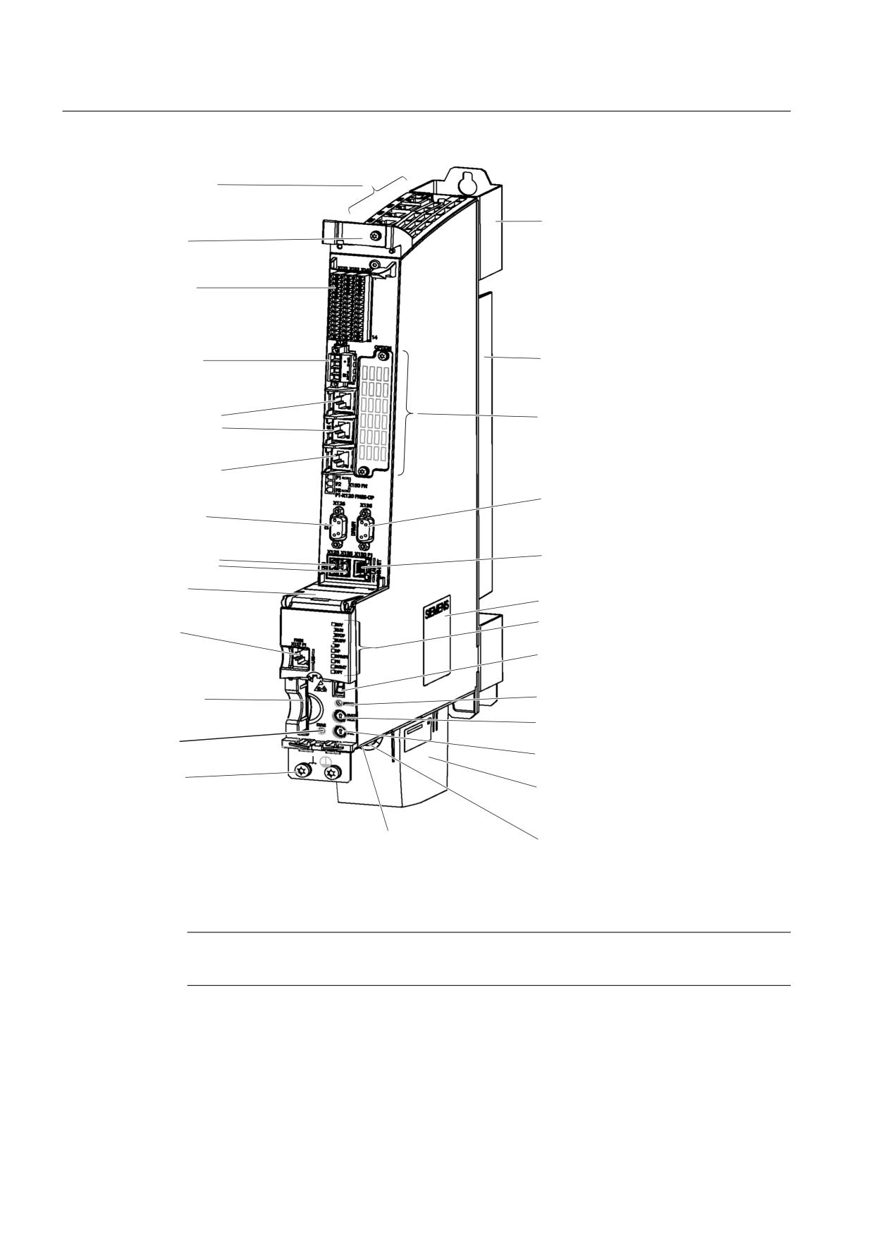
The following diagram shows an NCU 730.3 PN with its interfaces and control and display
elements (fault displays and status indicators). Please ensure that the structure of the NCUs
is virtually identical. There are only a few discrepancies, as follows:
● NCU 710.3 PN and NCU 710.3B PN have 4 instead of 6 DRIVE-CliQ interfaces.
● NCU 710.3 PN and all .3B versions do not have any cooling ribs and therefore a different
spacer.
NCU 7x0.3 PN, NCU 7x0.3B PN
Manual, 06/2014, 6FC5397-1EP40-5BA1
23
Description
3.2 Illustration
;
;
'5,9( &/L4 LQWHUIDFHV
6SDFHU
6KLHOG VXSSRUW
;
;
;
'LJLWDO LQSXWV RXWSXWV
&RROLQJ ULEV
;
(OHFWURQLFV SRZHU VXSSO\
;
3
3
2SWLRQ VORW FRYHUHG
352),1(7 ,2 LQWHUIDFH
;
3
31 ,( 23
;
(WKHUQHW LQWHUIDFH
352),%86 '3 03, LQWHUIDFH
;
352),%86 '3 LQWHUIDFH
;
3
;
OHIW
;
ULJKW
31 ,( 1(7
[ 86% LQWHUIDFH
(WKHUQHW LQWHUIDFH
0$& DGGUHVVHV
7\SH SODWH
; b3
/(' GLVSOD\V
31 ,(
(WKHUQHW LQWHUIDFH
VHJPHQW GLVSOD\
;
6ORW IRU &RPSDFW)ODVK
5HVHW EXWWRQ
&DUG
1&. FRPPLVVLRQLQJ VZLWFK
'LDJQRVWLFV EXWWRQ
3/& PRGH VHOHFWRU VZLWFK
3RWHQWLDO FRQQHFWLRQ
;
'RXEOH IDQ EDWWHU\ PRGXOH
;
XQGHUVLGH
;
XQGHUVLGH
7
7
7
0
56
QR IXQFWLRQ
PHDVXULQJ VRFNHWV
Figure 3-1
Illustration showing the NCU 730.3 PN
Note
For an NCU730.3B PN with PLC319, the option slot cannot be used.
NCU 7x0.3 PN, NCU 7x0.3B PN
24
Manual, 06/2014, 6FC5397-1EP40-5BA1
Description
3.3 Type plates
3.3
Type plates
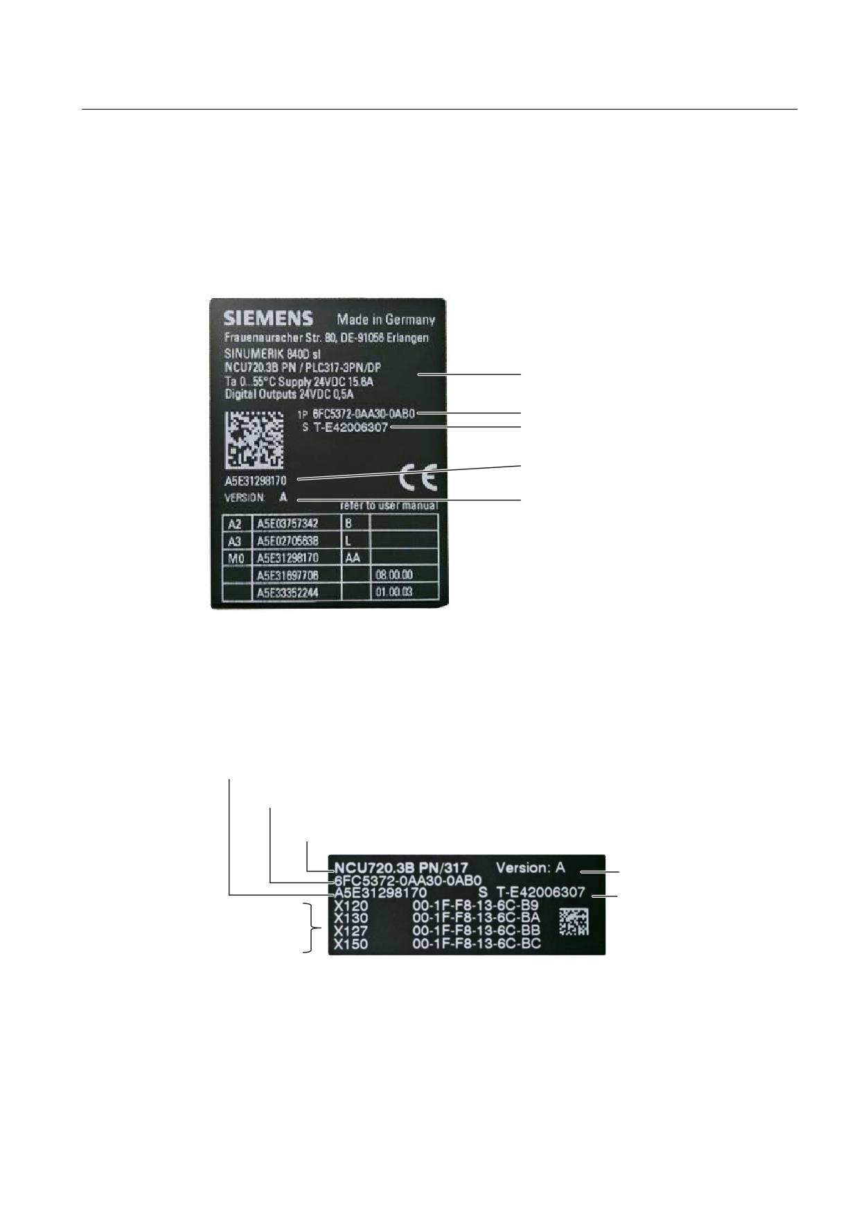
Side-mounted type plate
The following figure shows you all the information included on the type plate located on the
side of the unit.
&RPSRQHQW QDPH
2UGHU QXPEHU
6HULDO QXPEHU
0DWHULDO QXPEHU
+: YHUVLRQ
Figure 3-2
Type plate
MAC addresses
A type plate for the MAC addresses of the PROFINET and Ethernet interfaces is attached to
the front panel of the NCU:
,' QXPEHU
2UGHU QXPEHU
&RPSRQHQW QDPH
+: YHUVLRQ
6HULDO QXPEHU
0$& DGGUHVVHV
Figure 3-3
MAC addresses of the PROFINET/Ethernet interfaces
NCU 7x0.3 PN, NCU 7x0.3B PN
Manual, 06/2014, 6FC5397-1EP40-5BA1
25
Description
3.4 Operator control and display elements
You can see this type plate when you open the front cover of the NCU.
Note
The contents of the individual type plate fields on the actual NCU may differ from those
described in this Manual (e.g. updated product status, approvals and identifications not yet
issued, etc.).
3.4
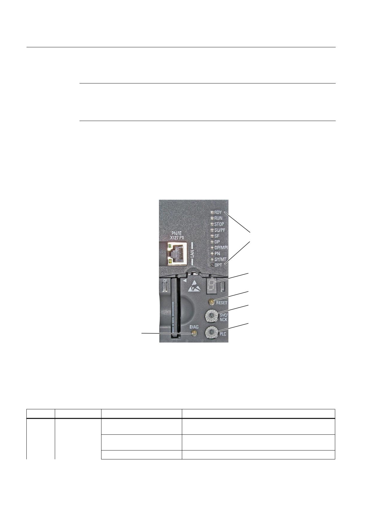
Operator control and display elements
3.4.1
Overview of operating and display elements
/(' GLVSOD\V
VHJPHQW GLVSOD\
5HVHW EXWWRQ
1&. VWDUW XS VZLWFK
3/& PRGH VHOHFWRU VZLWFK
'LDJQRVWLFV EXWWRQ ',$*
QR IXQFWLRQ
Figure 3-4
Position of operator control and display elements
3.4.2
LED displays
Table 3-1
Meaning of LED states
Name
Function
Status
Meaning
RDY
Ready
Red
There is at least one fault (e.g. RESET, watchdog monitoring
etc.) or the NCU is booting up.
Flashing red/orange
Error accessing CompactFlash Card
(0.5 Hz)
Orange
Accessing CompactFlash Card
NCU 7x0.3 PN, NCU 7x0.3B PN
26
Manual, 06/2014, 6FC5397-1EP40-5BA1

Description
3.4 Operator control and display elements
Name
Function
Status
Meaning
Flashing orange (0.5 Hz)
Updating the firmware of the connected DRIVE-CLiQ
components
Flashing orange (2 Hz)
Firmware update is complete for components. Wait for
POWER ON for the components in question.
Green
NC powered up and everything in cyclic mode
Flashing green/orange or red/
LED-supported recognition of connected DRIVE-CLiQ
orange (1 Hz)
component is activated: (p0124[0] = 1).
RUN
PLC RUN
Green
PLC ready to operate
STOP
PLC STOP
Orange
PLC stopped
SU/PF
PLC FORCE
Red
FORCE activated
SF
PLC SF
Red
PLC group error
DP
BUS1 F
Red
PROFIBUS group error X126
DP/MPI
BUS2 F
Red
PROFIBUS group error X136
PN
PN Fault
Red
PROFINET IO group error X150
SY/MT
MAINT
Orange
● Synchronization status (SY): No function
● Maintenance status (MT) of the NCU:
Maintenance request pending
OPT
-
-
No function
Important LED states
● If all the LEDs are flashing, the PLC must be reset via the mode selector (move switch to
position "3" to reboot).
● While the NCU is powering up, all LEDs briefly light up orange. You can carry out a detailed
diagnosis using a PG/PC and the operating software.
Additional references
● You can find a detailed description of LED states during power-up in the "NCU Operating
System (IM7)" section of the Basesoftware and Operating Software Commissioning Manual.
● For information on drive faults and alarms, see also:
SINAMICS S120/S150 List Manual (LH1)
3.4.3
7-segment display
Displaying messages
The 7-segment display is located behind the blanking plate of the NCU. It serves as a status
display during startup and performs the following tasks:
● Output of test and diagnostic messages.
● Output of status messages during booting
NCU 7x0.3 PN, NCU 7x0.3B PN
Manual, 06/2014, 6FC5397-1EP40-5BA1
27
Description
3.4 Operator control and display elements
Critical messages
● During normal operation, "6" appears here and the dot flashes.
● An "8" indicates that the fan is defective or that the NCU is operating without a fan.
Additional references
Basic Software and Operating Software Commissioning Manual (IM7), Chapter "System
startup displays".
3.4.4
RESET button
Arrangement
The RESET button is located behind the blanking cover.
Performing a reset operation
The reset operation resets the NCU and forces a new power-up. It is similar to a "Power On
Reset" except that the 24 V power supply does not have to be switched off.
NCU 7x0.3 PN, NCU 7x0.3B PN
28
Manual, 06/2014, 6FC5397-1EP40-5BA1

Description
3.5 Dual fan/battery module
3.4.5
Start-up and mode selector switch
Layout
The NCU has two coding rotary switches in the lower section of the front panel:
● The upper switch (labeled SVC/NCK) is the NCK commissioning switch.
Setting during normal operation: "0"
● The lower switch (labeled PLC) is the PLC mode selector switch.
Setting during normal operation: "0"
1&. FRPPLVVLRQLQJ VZLWFK
3/& PRGH VHOHFWRU VZLWFK
Figure 3-5
Startup and mode selector switch
Additional references
CNC Commissioning Manual Part 1 (NCK, PLC, drive)
3.5
Dual fan/battery module
Functions of the dual fan/battery module
The dual fan/battery module has the following tasks:
● Cooling the CPU by means of two redundant fans.
● Buffering of the real time clock.
The temperature inside the NCU and the correct functioning of the fan are monitored. Fan
faults are displayed and can be read out by means of the diagnostic buffer.
● Fan alarm ⇒ alarm 2110 "NCK temperature alarm": if one of the two fans no longer rotates
or the speed is out of tolerance.
● Fan fault ⇒ alarm 2120 "NCK fan alarm type %1": if none of the fans rotate.
If the software does not respond within approx. 1 minute, the components are shut down
automatically and the status is indicated by means of the red SF LED.
You can find more information on the alarms in the Diagnostics Manual.
NCU 7x0.3 PN, NCU 7x0.3B PN
Manual, 06/2014, 6FC5397-1EP40-5BA1
29

Description
3.5 Dual fan/battery module
Additional information on the diagnostics buffer is provided in the Function Manual Basic
Functions, see PLC signal DB10 DBX109.6 (fan temperature alarm).
Fans
The temperature is sensed at several locations within the NCU. The fan is automatically
switched in when the temperature thresholds set in the factory are exceeded. A hysteresis
function prevents frequent fan start/stop operations.
If natural convection is not sufficient to ensure cooling of the NCU, the fans integrated in the
dual fan/battery module are switched on when required (except for an NCU 730.3B PN with
PLC 319-3 DP/PN, in this case, the fan runs continuously):
● After switching the NCU on, the fan is activated for a brief period of time (function test)
before turning itself off again.
● The temperature is sensed at several locations within the NCU. The fan is automatically
switched in when the temperature thresholds set in the factory are exceeded. A hysteresis
function prevents frequent fan start/stop operations.
Note
The NCU cannot be operated without fans, i.e. it will not power up if the dual fan/battery
module is not functioning. The RDY LED flashes red/orange with 0.5 Hz, all other LEDs light
up orange. The state can only be exited by switching the NCU off.
Battery
A 3 V lithium battery is installed in the dual fan/battery module; this can be replaced when
required. The battery is pre-assembled with an approximately 4 cm long cable with plug
connector. The appropriate mating connector is attached to a small circuit board for connection
in the dual fan/battery module.
Note
Please dispose of used batteries in the specially provided collection points on site. This will
ensure that the batteries are recycled in the correct manner or treated as special waste.
Note
The backup time of a used type of battery is at least 3 years. Exceeding this backup time
risks loss of data.
NCU 7x0.3 PN, NCU 7x0.3B PN
30
Manual, 06/2014, 6FC5397-1EP40-5BA1
Application planning
4
4.1
Secondary electrical conditions
4.1.1
Grounding concept
Components
The SINUMERIK 840D sl system consists of a number of individual components which have
been designed so that the system complies with the appropriate EMC and safety standards.
The individual system components are:
● Numerical Control Unit (NCU):
● Machine Control Panel MCP, Machine Push Button Panel MPP
● Keyboard
● Operator panels (operator panel front + TCU/PCU)
● Distributor box and handheld unit
● S7-300 I/O with IM 153 interface module
Grounding measures
The individual modules are attached to a metal cabinet panel. Insulating paints on the mounting
points must be removed.
It is permissible to have a cluster of operator components for ground connection/PA.
Example: The control panel on the swivel arm.
It is sufficient in this instance to connect the ground connections of, for example, the PCU,
TCU, and operator panel front using a cable and to route a shared grounding conductor to the
central ground connection in the control cabinet.
Additional references
Configuration Manual, EMC Guidelines
4.1.2
RI suppression measures
In addition to the protective grounding of system components, special precautions must be
taken to ensure safe, fault-free operation of the system. These measures include shielded
signal lines, special equipotential bonding connections, and isolation and shielding
measures.
NCU 7x0.3 PN, NCU 7x0.3B PN
Manual, 06/2014, 6FC5397-1EP40-5BA1
31
Application planning
4.1 Secondary electrical conditions
Shielded signal lines
● For safe and smooth operation of the system, the specified cables must be used. Please
refer to the chapter titled Connection.
● For digital signal transmission, the shield must have a conductive connection at both sides
of the housing.
Cable definitions
● Signal cables (example)
- Data cables (Ethernet, PROFIBUS, PROFINET, sensor cables, etc.)
- Digital inputs/outputs
- EMERGENCY OFF lines
● Power cables (example)
- Supply voltage 1 x 230 V AC or 3 x 400 V AC
- Motor cables
Rules for routing cables
In order to maximize noise immunity for the complete system (controller, power section,
machine) the following EMC measures must be observed:
● A minimum distance of 200 mm is to be observed between the signal lines and power cables.
● If necessary, signal and load cables may cross one another (if possible, at an angle of 90°),
but must never be laid close or parallel to one another.
● Only use cables approved by Siemens for the signal lines from and to the NCU.
● Signal cables may not be routed close to strong external magnetic fields (e.g., motors and
transformers).
● If signal lines cannot be routed a sufficient distance away from other cables, they must be
installed in grounded cable ducts (metal).
Note
For more specifications regarding interference suppression measures and connection of
shielded cables, see
References
Configuration Manual, EMC Guidelines
NCU 7x0.3 PN, NCU 7x0.3B PN
32
Manual, 06/2014, 6FC5397-1EP40-5BA1

Application planning
4.2 Climatic and mechanical environmental conditions
EMC limit values in South Korea
The EMC limit values to be complied with for South Korea correspond to the limit values of the
EMC product standard for variable-speed electric drives EN 61800-3, Category C2, or limit
value class A, Group 1 according to EN 55011. By applying suitable supplementary measures,
the limit values according to Category C2 or according to limit value class A, Group 1, are
maintained. Further, additional measures may be required, for instance, using an additional
radio interference suppression filter (EMC filter).
The measures for EMC-compliant design of the system are described in detail in this manual
respectively in the Installation Guideline EMC.
Please note that the final statement on compliance with the standard is given by the respective
label attached to the individual unit.
4.2
Climatic and mechanical environmental conditions
4.2.1
Shipping and storage conditions
The components of the SINUMERIK 840D sl system exceed the requirements according to
EN 61800-2 with regard to shipping and storage conditions.
The following data applies under the following conditions:
● Long-term storage in the transport and product packaging:
At weather-protected locations that have continuous contact with outside air through
openings.
● Transport in the transport packaging:
- In unventilated containers under conditions not protected from weather effects.
- In the “cold" in accordance with outside air.
- Air transport in the air-conditioned cargo hold.
Table 4-1
Ambient conditions during storage and transport
Type of condition
Permissible range/class
Transport
Storage
Classification
EN 60721-3-2
EN 60721-3-1
Climate class
2K4
1K4
Ambient temperature
From -40° C to +70° C
From -25° C to +55° C
NCU 7x0.3 PN, NCU 7x0.3B PN
Manual, 06/2014, 6FC5397-1EP40-5BA1
33

Application planning
4.2 Climatic and mechanical environmental conditions
Type of condition
Permissible range/class
Biological environmental
2B1 1)
1B1 1)
conditions
Chemically active
2C2 2)
1C2 2)
environmental conditions
Maximum permissible
Direct interaction in air/air:
30 k/h
temperature change
-40°/+30° C at 95% relative
humidity
Relative humidity
5 to 95 %
Precipitation, rain
6 mm/min 1)
Not permitted
Water other than rain
1 m/s and wet loading surfaces 3)
Not
1 m/s and wet
permissible 4)
loading surfaces 3)
Height
Max. 4,000 m above sea level
Condensation, splash water,
Permissible
Not
Permissible 3)
icing, salt spray
permissible 4)
1)
Mold growth, slime, rodents, termites and other animal vermin are not permissible.
2)
In marine- and weather-resistant transport packaging (container).
3)
For storage in the transport packaging.
4)
For storage in the product packaging.
Note
Remove the transport protective foil and packaging material before installing the components.
Shipping backup batteries
Backup batteries may only be shipped in the original packaging. No special authorization is
required to ship backup batteries. The lithium content is approximately 300 mg.
Note
The backup battery is classified as a hazardous substance, Class 9, in accordance with the
relevant air-freight transportation regulations.
Storage of backup batteries
Always store backup batteries in a cool and dry place. The batteries have a maximum shelf
life of 10 years.
NCU 7x0.3 PN, NCU 7x0.3B PN
34
Manual, 06/2014, 6FC5397-1EP40-5BA1
Application planning
4.2 Climatic and mechanical environmental conditions
Rules for handling backup batteries
WARNING
Incorrect handling of backup batteries can lead to a risk of ignition, explosion and combustion
The stipulations of DIN EN 60086-4, in particular regarding avoidance of mechanical or
electrical tampering of any kind, must be complied with.
● Do not open a battery. Replace a faulty battery only with the same type.
● Only purchase the batteries through Siemens (see Ordering data (Page 21)).
● Always try to return low batteries to the manufacturer or deliver these to a registered
recycling company.
4.2.2
Operating conditions
The components of the SINUMERIK 840D sl system are intended for a weatherproof, fixed
location. The documented environmental conditions apply to the climate in the immediate
vicinity of the units and to the entry of the cooling air. They exceed the requirements according
to EN 60204-1, EN 61800-2, EN 61131-2 and IEC 62477-1.
Table 4-2
Ambient conditions for operation
Ambient conditions
Application areas
Remarks
Climatic environmental conditions
Climate class
3K3
According to EN 60721-3-3
Limit temperatures at
0 °C ... 55 °C
From an altitude of 2000 m, the max. ambient
100% load
temperature decreases by 7° C for every 1000 m
increase in altitude - derating.
Relative humidity
5% to 95% (60% when corrosive gases and/or dusts are present)
Condensation, icing,
Not permitted
drip, spray and splash
water
Max. installation
1000 m above sea
Without thermal derating
altitude
level
2000 m above sea
With insulation
level
> 2000 m ... 5000 m
Clearances for an operating voltage of 50 V at 5000 m
above sea level
Biological, chemical and mechanical influences, pollutants
Biological environmental conditions
Class 3B1 according to EN 60 721-3-3:
Mold, mold growth, slime, rodents, termite and other
animal vermin are not permissible.
Mechanically active environmental conditions
Class 3S1 according to EN 60721-3-3:
Conductive dust not permitted.
Classification of the mechanical
3M3 for components on the machine
environment
3M1 / 3M2 for components in the control cabinet
NCU 7x0.3 PN, NCU 7x0.3B PN
Manual, 06/2014, 6FC5397-1EP40-5BA1
35

Application planning
4.3 Recycling and disposal
Ambient conditions
Application areas
Remarks
Pollution degree
2
EMC conducted / radiation
Class C3 according to EN 61800-3
Note
The user must consider radio interference for the complete system. Particular attention should
be paid to cabling. Please contact your sales representative for assistance and support.
If compliance with limit value class C2 is required, please contact your local Siemens sales
partner.
4.3
Recycling and disposal
Products should be disposed of corresponding to the relevant national regulations.
The products described in this manual can be mostly recycled due to the fact that they contain
very few damaging substances. To recycle and dispose of your old device in an
environmentally friendly way, please contact an appropriate disposal company.
NCU 7x0.3 PN, NCU 7x0.3B PN
36
Manual, 06/2014, 6FC5397-1EP40-5BA1
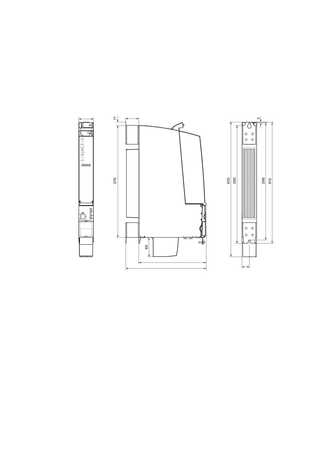
Dimension drawings
5
Figure 5-1
Dimension drawing NCU 720.3 PN and NCU 730.3 PN; dimensions in mm
NCU 7x0.3 PN, NCU 7x0.3B PN
Manual, 06/2014, 6FC5397-1EP40-5BA1
37
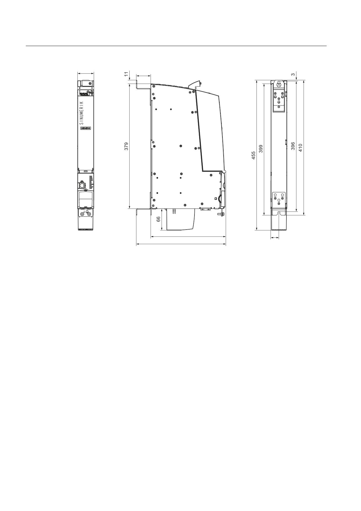
Dimension drawings
Figure 5-2
Dimension drawing NCU 710.3 PN, NCU 710.3B PN, NCU 720.3B PN and NCU 730.3B
PN; dimensions in mm
NCU 7x0.3 PN, NCU 7x0.3B PN
38
Manual, 06/2014, 6FC5397-1EP40-5BA1

Assembling
6
6.1
Safety information
Note
The NCU is exclusively intended for installation in ESD-protected zones. The CE-associated
ESD interference immunity limit values can only be achieved via installation in the control
cabinet. Only make physical contact using appropriate ESD protective measures.
Open equipment
These modules are open equipment. This means they may only be installed in housings,
cabinets or in electrical service rooms that can be entered or accessed exclusively by means
of a key or tool. Housings, cabinets, or electrical equipment rooms may only be accessed by
trained or authorized personnel. An external fire protection casing is required.
NOTICE
The module can be damaged if power is connected to the NCU when installing/removing it
When installing the NCU, the system and the NCU must be disconnected (brought into a no
voltage condition).
Control cabinet installation
Please refer to the SINAMICS documentation for more details.
WARNING
Risk of fire through overheating if there are insufficient ventilation clearances
Inadequate ventilation clearances cause overheating with a risk for personnel due to smoke
and fire. Further, this can result in increased failures and a shorter service life of devices/
systems.
It is essential that you maintain 80 mm ventilation clearances above and below the NCU.
NOTICE
Risk of destroying components resulting from high discharge currents
The NCU or other PROFIBUS or PROFINET devices can be destroyed if significant discharge
currents flow through the PROFIBUS or PROFINET cable.
Between parts of a plant or system, use a function equipotential bonding conductor with a
minimum cross-section of 25 mm².
NCU 7x0.3 PN, NCU 7x0.3B PN
Manual, 06/2014, 6FC5397-1EP40-5BA1
39

Assembling
6.2 Designs
NOTICE
Cables not certified for the application can damage modules
Only use Siemens cables for the DRIVE-CLiQ connections.
Note
Protecting unused DRIVE-CLiQ interfaces
Close any unused DRIVE-CLiQ interfaces using the blanking covers provided.
Note
Function equipotential bonding for distributed DRIVE-CLiQ nodes
Integrate all of the components that are connected via DRIVE-CLiQ in the functional
equipotential bonding concept. The connection should be preferably established by mounting
on metallic bare machine and plant components that are connected with one another using an
equipotential bonding conductor.
Alternatively, you can establish equipotential bonding using a conductor (min. 6 mm²), which
as far as possible, is routed in parallel to the DRIVE-CLiQ cable. This applies to all distributed
DRIVE-CLiQ nodes such as DM20, SME2x, SME12x, etc.
If you have any further questions or are looking for particular solutions, you can contact the
Systems Engineering Plant Chemnitz directly.
6.2
Designs
The NCU is installed in a control cabinet along with the SINAMICS components.
Designs
The NCU is preferably mounted vertically on the rear panel of the control cabinet. The following
fixing options are available:
● Mounting using spacers.
● Mounting without spacers:
- for NCU 710.3 PN, NCU 710.3B PN, NCU 720.3B PN and NCU 730.3B PN.
- for external heat dissipation for NCU 720.3 PN and NCU 730.3 PN.
Note
The procedures described below for mounting the NCU refer to the delivery condition of the
NCU: the upper clip is pulled in and the spacers are mounted.
NCU 7x0.3 PN, NCU 7x0.3B PN
40
Manual, 06/2014, 6FC5397-1EP40-5BA1
Assembling
6.4 Mounting the NCU without spacers
6.3
Fix the NCU using spacers
Introduction
Spacers can be used to mount the NCU on a bare-metal highly-conductive rear panel of a
control cabinet.
Note
The mechanical stability for horizontal mounting is only guaranteed with the help of supports
or similar. These must be clarified depending on the specific application and are not part of
this documentation.
Procedure
Mount the NCU using two M6 screws (6 Nm tightening torque) on the spacers on the rear of
the control cabinet.
6.4
Mounting the NCU without spacers
Introduction
The NCU 710.3 PN and all of the .3B versions can be directly mounted onto the rear panel of
the control cabinet without spacers.
Procedure
The NCU has a metal clip on the upper rear side that is pushed in and fixed using 3x M3 torx
screws when supplied.
1. Remove the spacers with a T10 screwdriver .
2. Loosen the three M3 screws on the clip and push the clip up until the upper hole protrudes
beyond the housing.
3. Retighten the 3x M3 screws (0.8 Nm) of the clip.
4. Attach the top and bottom of the NCU directly on the rear panel of the control cabinet using
two M6 screws (6 Nm);
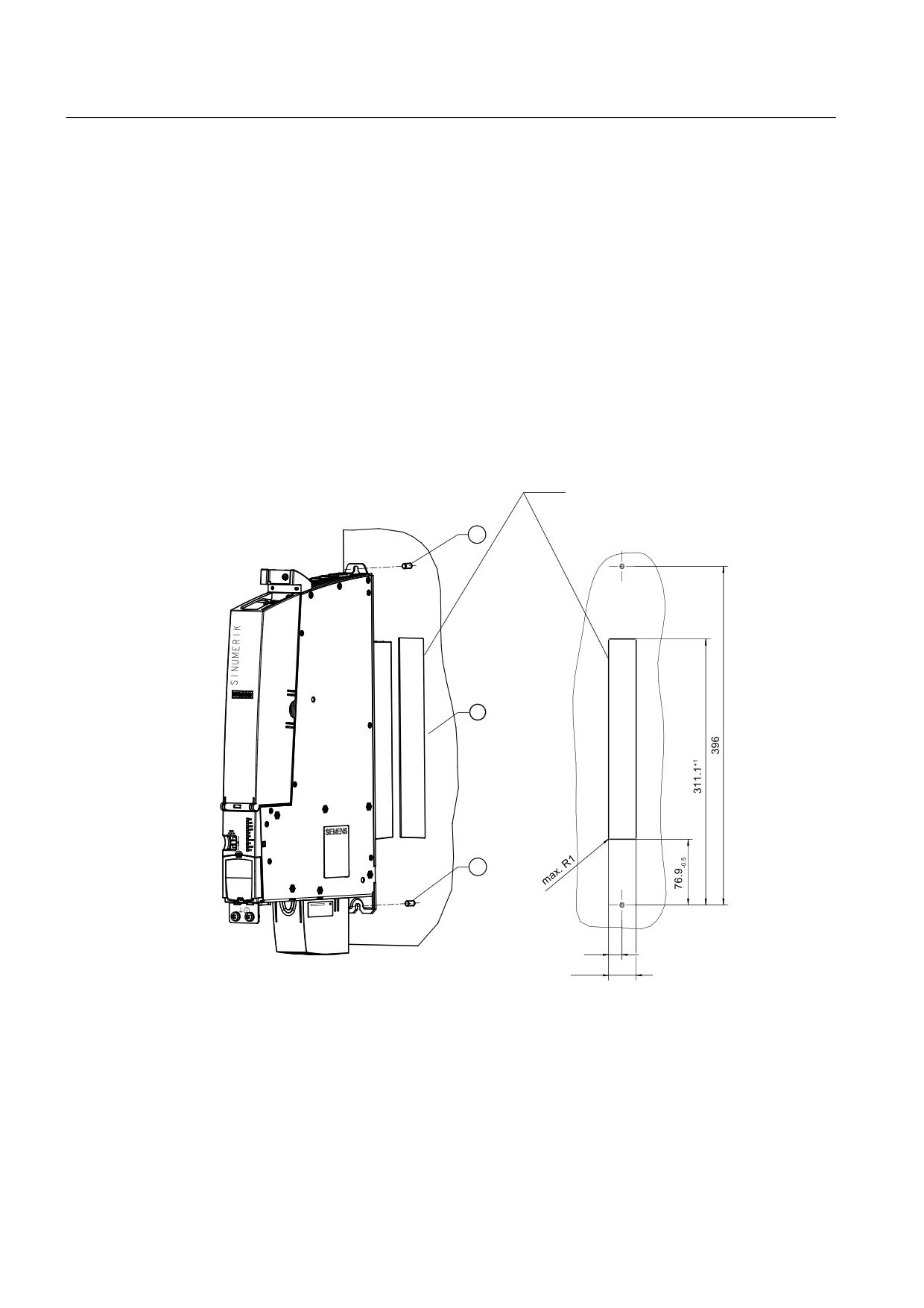
Distance between the drilled holes, see Figure 6-1 Panel cutout (dimensions in mm)
(Page 42)
NCU 7x0.3 PN, NCU 7x0.3B PN
Manual, 06/2014, 6FC5397-1EP40-5BA1
41
Assembling
6.5 Mounting the NCU for external cooling
6.5
Mounting the NCU for external cooling
Introduction
If the NCU must be externally cooled via the cooling ribs, then it can be directly mounted onto
the rear of the control cabinet panel without using spacers.
Prerequisites
● You have an NCU 720.3 PN or NCU 730.3 PN.
● The bushing for the cooling ribs (external heat sink) has been fitted in the rear wall of the
control cabinet.
● Please ensure that the surface around the seal is both clean and flat ② (please see the
diagram "Panel cutout").
&XWRXW IRU KHDW VLQN
IRU H[WHUQDO FRROLQJ
Figure 6-1
Panel cutout (dimensions in mm)
NCU 7x0.3 PN, NCU 7x0.3B PN
42
Manual, 06/2014, 6FC5397-1EP40-5BA1
Assembling
6.5 Mounting the NCU for external cooling
Procedure
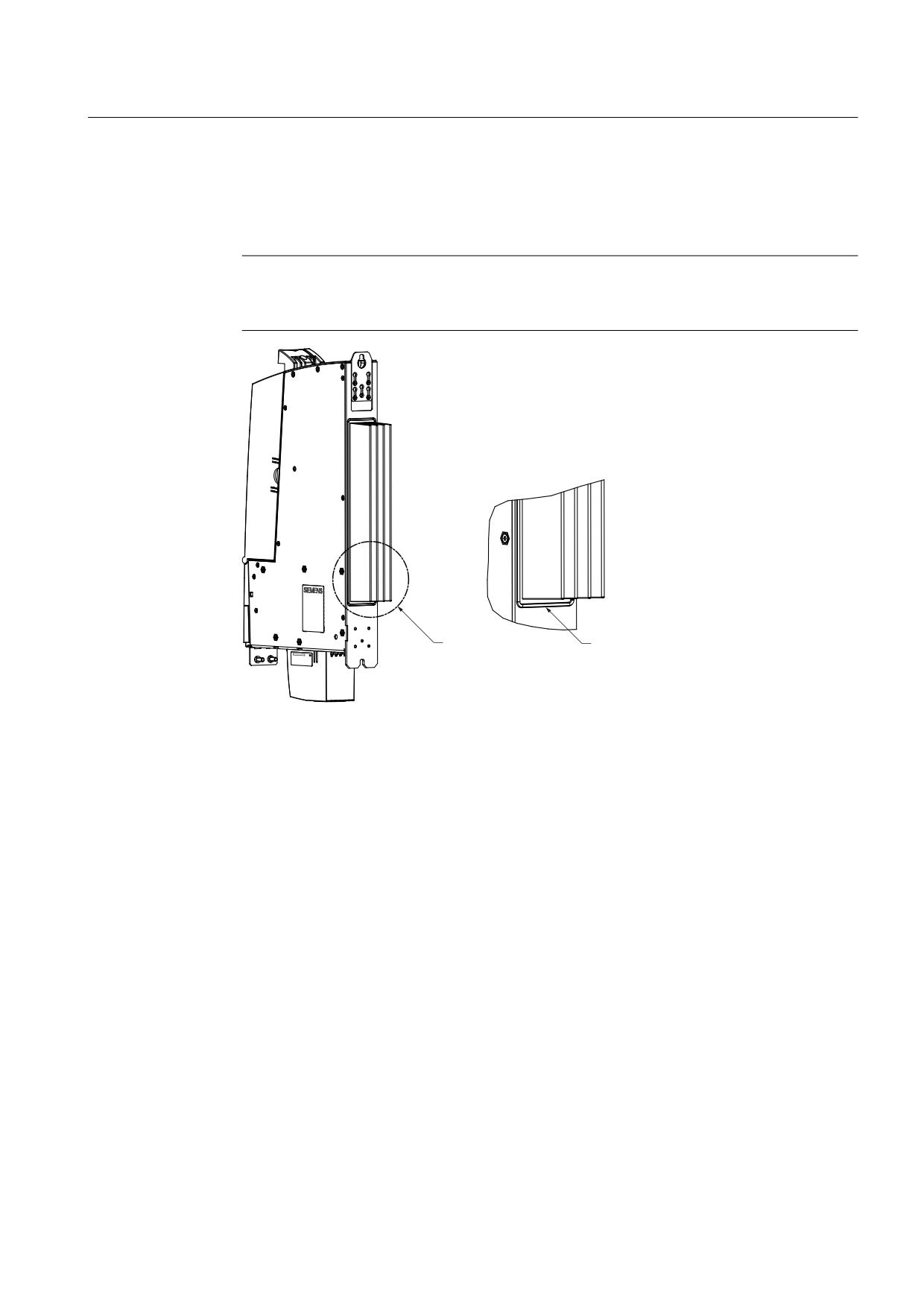
1. Remove the spacers.
2. Fit the seal around the cooling ribs of the NCU.
Note
The seal is not included with the NCU. They must be additionally ordered, see Ordering
data (Page 21).
$
,QVHUWLQJ WKH VHDO IRU H[WHUQDO
$
FRROLQJ LQ KHDW VLQN JURRYH
3. Loosen the three M3 screws on the upper clip and push the clip up until the upper hole
protrudes beyond the housing.
4. Retighten the 3x M3 screws (0.8 Nm) of the clip.
5. Mount the top and bottom of the NCU with heat sink directly on the rear panel of the control
cabinet using two M6 screws (6 Nm) (① see figure titled "Panel cutout").
NCU 7x0.3 PN, NCU 7x0.3B PN
Manual, 06/2014, 6FC5397-1EP40-5BA1
43
Connecting
7
7.1
Overview
Connection options
The NCU has a series of interfaces via which the power supply and the remaining system
components are connected. The front cover of the NCU must be open to make the connections.
● The various SINAMICS components are connected with the NCU via DRIVE-CLiQ.
● Actuators and sensors can be connected to the digital inputs/outputs.
● The NCUs have the following communication options:
- PROFIBUS DP, MPI, Ethernet
- PROFINET
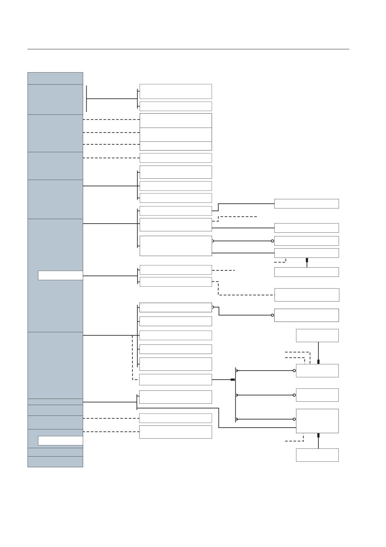
The following overview shows an example of the various interfaces and their connection
options.
NCU 7x0.3 PN, NCU 7x0.3B PN
Manual, 06/2014, 6FC5397-1EP40-5BA1
45
Connecting
7.1 Overview
SINUMERIK 840D sl
NCU 7x0.3 PN
DRIVE-CLiQ
X100
SINAMICS S120
X101
Motor / Line Modules
X102
X103
X1041)
NX10.3 / NX15.3
X1051)
6 digital inputs and
Digital I/O
X122
4 digital inputs/outputs
X132
6 digital inputs and
4 digital inputs/outputs
X142
4 digital inputs and outputs each
24 V DC
;
Power supply
SIMATIC
PROFINET IO
Order No.
PROFINET
X150 P1
SINAMICS S120 CU3x0-2 PN
Prefabricated cable
X150 P2
PP 72/48 PN I/O module
3)
Operator panel front OP / TP
TCU x0.2 / PCU 50.5
6FX1440-4B...
Emergency stop/agreement circuit
Ethernet
X120
Connection box/
connection module PN
6FC5348-0AA08-3AA0
Handheld unit HT 2 / HT 8
6FX8002-2CP00-...
MCP 310C PN / MCP 310 PN
Electronic handwheel
MCP 483C PN / MCP 483 PN
≤ 25 m
MPP 310 IE H / MPP 483 IE
Connection kit
6FX2006-1BG11
Emergency
stop/agreement circuit
3)
CBE30-2 module
NCU-Link
Mini handheld unit
Option slot
COM1.3 module
Device with RS232C
interface
MCP 483 / MCP 310 / MPP 483
6FX8002-2CP00-...
Electronic handwheel
≤ 25 m
SINAMICS S120 CU 3x0-2 DP
Mini
PROFIBUS DP
X126
ADI 4
handheld unit
3)
PP 72/48 I/O module
Emergency stop/agreement circuit
PLC inputs
SIMATIC I/O
PROFIBUS DP
6FX8002-2CP00-
Connection kit
≤ 25 m
6FX2006-1BG03
Handwheel connection module 2)
6FX8002-2CP00-
Electronic
SIMATIC I/O
PROFIBUS DP
≤ 25 m
Handwheel
PROFIBUS DP/MPIX136
USB
X125
X135
Distribution list
6FX8002-2CP00-
Ethernet
X130
Factory network
HHU type MPI
≤ 25 m
6FX2006-1BC01
Programming device PG/
6FX2006-1BH01
Ethernet
X127
TS adapter
Emergency stop/agreement circuit
CF card
X109
3)
Measuring sockets
X141
1) Not for NCU 710.3 PN.
Handheld unit
2) Omitted when connected via MCP or MPP.
Type B-MPI
RS232C
X140
(Service)
3) Not included in the scope of supply.
Figure 7-1
Options of connecting an NCU
NCU 7x0.3 PN, NCU 7x0.3B PN
46
Manual, 06/2014, 6FC5397-1EP40-5BA1

Connecting
7.2 Safety information for wiring
Interface overview
Table 7-1
Overview of the interfaces that can be used
Interface
Designation
Connector type
DRIVE-CLiQ
X100 - X105
Spec. RJ45 socket
Ethernet IE1/OP
X120
Standard RJ45 socket
Ethernet IE2/NET
X130
Standard RJ45 socket
Ethernet (service socket)
X127
Standard RJ45 socket
PROFINET
X150; ports 1, 2
Standard RJ45 socket
Digital inputs/outputs
X122, X132, X142
Screw terminals, 3x14 pin
24 V power supply
X124
Screw terminals, 4-pin
USB
X125, X135
USB socket
PROFIBUS DP1
X126
9-pin SUB-D socket
PROFIBUS DP2/MPI
X136
9-pin SUB-D socket
RS232 (service socket)
X140
9-pin SUB D plug connector
Measuring sockets (T0, T1, T2,
X141, X143
Sockets on the printed-circuit board
and M)
CompactFlash Card
X109
50-pin socket
Dual fan/battery module
X190
6-pin
7.2
Safety information for wiring
Note the following:
Safety information
NOTICE
The module can be damaged if power is connected when connecting up the NCU
When connecting the NCU, the system and the NCU must be disconnected (brought into a
no voltage condition).
Note
If your axis grouping contains a Smart Line Module without DRIVE-CLiQ (5 kW or 10 kW),
you must assign the Smart Line Module enabling signal to digital input X122.1 on the NCU.
NCU 7x0.3 PN, NCU 7x0.3B PN
Manual, 06/2014, 6FC5397-1EP40-5BA1
47
Connecting
7.3 Opening the front cover
7.3
Opening the front cover
Introduction
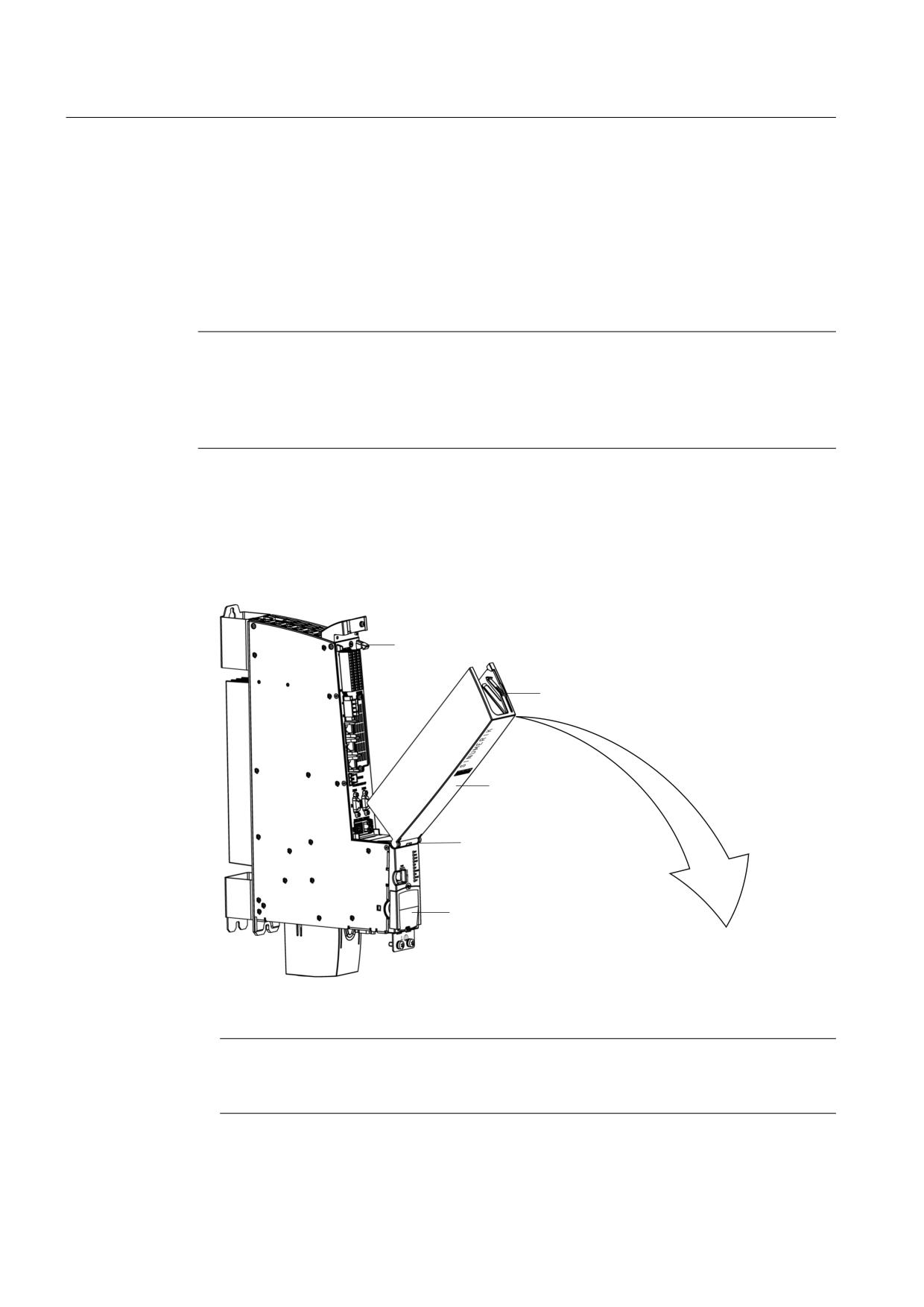
The interfaces are concealed behind a front cover. You must fold down this cover before you
can wire up the interfaces. When the front cover is closed (flipped up), it automatically locks
into place by means of a hook on the connector panel.
Note
Replacement of the front cover in the event of servicing
A hinge connects the front cover to the front of the housing. In order to replace them, it can
easily be removed in the open state (45° angle) by pulling it slightly. It is installed in the same
way, at a 45° angle, by slightly pressing on the hinge.
Procedure
1. Release the latch on the inside of the front cover (the front cover is open and in the up
position) through slight pressure on it from the top.
2. Fold the front cover down to the front and bottom to give access to the interfaces.
+RRN
8QORFNLQJ KRRN
)URQW FRYHU
3LYRWLQJ KLQJH
%ODQNLQJ SODWH
Figure 7-2
Removing the front cover
Note
All cables must be routed vertically upwards to the fullest extent possible so that the front
cover can be closed.
NCU 7x0.3 PN, NCU 7x0.3B PN
48
Manual, 06/2014, 6FC5397-1EP40-5BA1

Connecting
7.4 Power supply
7.4
Power supply
7.4.1
Application
This interface is provided exclusively for connection of the external power supply.
Note
When using external power supplies (e.g. SITOP), the ground potential must be connected
with the protective ground terminal (PELV).
Pin assignment
Table 7-2
Power supply X124
Pin
Signal name
Signal type
Meaning
+
P24
VI
Power supply 24 V
+
P24
VI
M
M
VO
Ground
M
M
VO
Signal type: VI = voltage input;VO = voltage output
Note
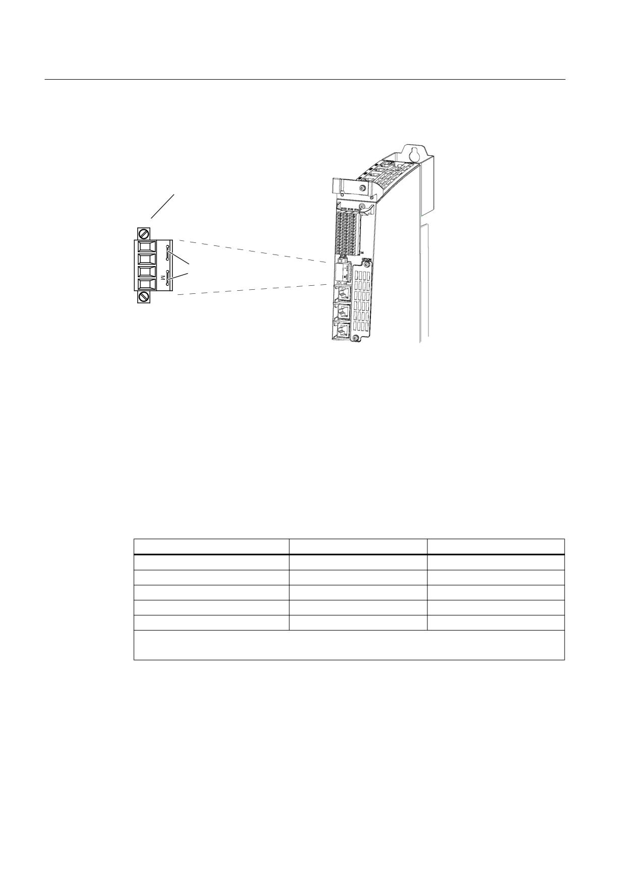
The two "+" or "M" terminals are jumpered in the connector. This ensures the 24 V voltage
is looped through.
NCU 7x0.3 PN, NCU 7x0.3B PN
Manual, 06/2014, 6FC5397-1EP40-5BA1
49
Connecting
7.4 Power supply
Position of power supply interface
3RZHU VXSSO\ FRQQHFWRU
-XPSHU
Figure 7-3
Power supply interface
7.4.2
Requirements for the power supply
External 24 V power supply
Power is supplied to the NCU by an external 24 V power supply (e.g.: SITOP). The following
power consumption values for an NCU provide a configuration basis for calculating the 24 V
DC power supply.
Table 7-3
Input voltage specification
Typ. current consumption 1)
Max. power consumption 2)
NCU 710.3 PN / NCU 710.3B PN
0.9 A
11.7 A
NCU 720.3 PN / NCU 730.3 PN
1.9 A
15.6 A
NCU 720.3B PN
0.94 A
14.6 A
NCU 730.3B PN (PLC 317)
1 A
14.6 A
NCU 730.3B PN (PLC 319)
1.25 A
15 A
1) NCU only (processor, memory, etc.)
2) NCU with full load at all outputs (digital outputs, USB, DRIVE-CLiQ, PROFIBUS DP etc.)
NCU 7x0.3 PN, NCU 7x0.3B PN
50
Manual, 06/2014, 6FC5397-1EP40-5BA1

Connecting
7.4 Power supply
Requirements of DC power supplies
DANGER
Danger of death caused by unsafe power supply
The DC power supply must be implemented as a circuit of Category PELV/DVC A according
to EN 61800-5-1.
WARNING
Inadequately fused supply cables can be life-threatening
In the case of supply lines > 10 m, protectors must be installed at the device input in order
to protect against lightning (surge).
The DC power supply must be connected to the ground/shield of the NCU for EMC and/or
functional reasons. For EMC reasons, this connection should only be made at one point. As
a rule, the connection is provided as standard in the S7-300 I/Os. In exceptional
circumstances when this is not the case, the ground connection should be made on the
grounding rail of the control cabinet; please also refer to /EMC/EMC Installation Guide.
Table 7-4
DC power supply requirements in accordance with EN 61131-2
Rated voltage
24 V DC
Voltage range (average value)
20.4 V DC to 28.8 V DC
Voltage ripple peak-to-peak
5% (unfiltered 6-pulse rectification)
Booting time at POWER ON
Any
Non-periodic overvoltages
≤ 35 V
Duration of overvoltage
≤ 500 ms
Recovery time
≥ 50 s
Events per hour
≤ 10
Transient voltage interruptions
Outage time
≤ 3 ms
Recovery time
≥ 10 s
Events per hour
≤ 10
Additional references
Recommended power supply units and tables for calculating the current drawn for SINAMICS
S120 module lineups can be found in chapter "Control cabinet design and EMC Booksize" of
the "SINAMICS S120 Booksize power units" manual.
NCU 7x0.3 PN, NCU 7x0.3B PN
Manual, 06/2014, 6FC5397-1EP40-5BA1
51

Connecting
7.5 DRIVE-CLiQ components
7.4.3
Connecting the power supply
Wiring the screw-type terminal block
The required 24 V DC load current supply is wired to screw-type terminal block X124.
Power cables
Table 7-5
Cable specification for X124
Features
Version
Connector type
4-pin screw terminal
Connectable cable types and conductor cross-sections
● Rigid
●
0.2 mm² to 2.5 mm²
● Flexible
●
0.2 mm² to 2.5 mm²
● Flexible, with end sleeve without plastic sleeve
●
0.2 mm² to 2.5 mm²
● Flexible, with end sleeve with plastic sleeve
●
0.2 mm² to 1.5 mm²
● AWG / kcmil
●
22 to 12
Stripped length
6-7 mm
Tool
Screwdriver 0.5 x 3 mm (M2.5)
Tightening torque
0.4 to 0.5 Nm
Max. current carrying capacity, incl. loop-through
20 A *) (15 A according to UL/CSA)
Max. cable length
10 m
*)
This value must be taken into consideration for the current-carrying capacity of the power supply
cable.
7.5
DRIVE-CLiQ components
7.5.1
Application
The components of the SINAMICS S120 drive family and the NCU are interconnected using
DRIVE-CLiQ. When connecting the components, please follow the rules in the documentation
below without exception:
The "Communication in the system" chapter of the "Machine configuration guidelines" System
Manual.
Properties
● Automatic detection of components
●
24 V/450 mA per DRIVE CLiQ interface is provided for the connection of encoders and
measuring systems
NCU 7x0.3 PN, NCU 7x0.3B PN
52
Manual, 06/2014, 6FC5397-1EP40-5BA1
Connecting
7.5 DRIVE-CLiQ components
DRIVE-CLiQ pin assignment
Table 7-6
DRIVE-CLiQ interface X100 - X105
PIN
Signal name
Signal type
Meaning
1
TXP
O
Transmit data +
2
TXN
O
Transmit data -
3
RXP
I
Receive data +
4
-
-
Reserved, do not use
5
-
-
Reserved, do not use
6
RXN
I
Receive data -
7
-
-
Reserved, do not use
8
-
-
Reserved, do not use
A
+ (24 V)
VO
Voltage supply for DRIVE-CLiQ, 450 mA maximum
B
M (0 V)
VO
Ground to 24 V
Signal type: I = Input; O = Output; VO = Voltage Output
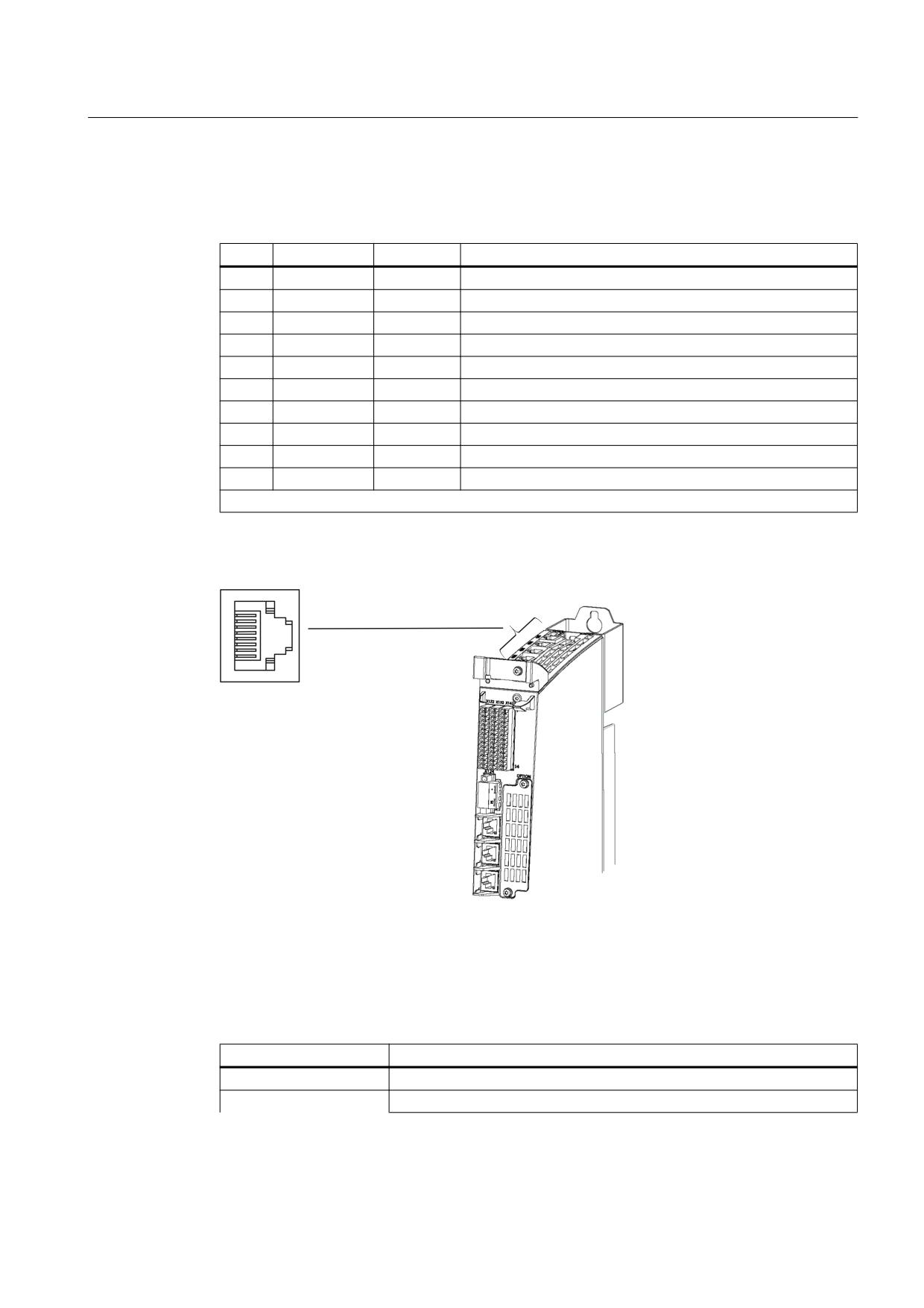
Position of the DRIVE-CLiQ interfaces
B
8
1
A
Figure 7-4
DRIVE-CLiQ interfaces
Cable specification
Table 7-7
Cable specification for X100 - X105
Characteristic
Version
Connector type
RJ45 socket
Cable type
DRIVE-CLiQ standard (inside the control cabinet)
NCU 7x0.3 PN, NCU 7x0.3B PN
Manual, 06/2014, 6FC5397-1EP40-5BA1
53

Connecting
7.5 DRIVE-CLiQ components
Characteristic
Version
MOTION CONNECT (outside the control cabinet)
Max. cable length
70 m
7.5.2
Connectable DRIVE-CLiQ components
Components
As a rule, all SINAMICS/SIMOTION components approved for SINUMERIK can be connected
to an NCU using DRIVE-CLiQ.
Table 7-8
Components with DRIVE-CLiQ
Component
Description
NX10.3 / 15.3
Drive expansion module for up to 6 axes
SINAMICS S120, system components, booksize format
Smart / Active / Basic
Line Modules provide the central power supply to the DC link.
Line Module
Single / Double Motor Module
Motor Modules draw their power from the DC link to supply the
connected motors.
HF Motor Module
Operates as inverter and provides the energy for the
connected motor - High Frequency Drive.
SINAMICS S120, system components, chassis format
Smart / Active / Basic Line
Line Modules provide the central power supply to the DC link.
Module
Motor Module
Motor Modules draw their power from the DC link to supply the
connected motors.
Power Module
Power Modules provide the energy for the connected motor.
CUA31
Adapter to connect a Power Module to the NCU.
SINAMICS S120 Combi (only in connection with NCU 710.3)
Power Module
Integrated infeed, Motor Modules for 3 or 4 axs and TTL encoder
evaluation for the spindle.
Motor Module Booksize
Expansion axes for Power Modules.
Compact
SINAMICS S120, additional system components
SMC10/20/30
Cabinet-Mounted Sensor Modules are needed when a motor with a
DRIVE-CLiQ interface is not available and when external encoders are
required in addition to the motor encoder.
SME20 / 25
Measuring systems outside the cabinet can be connected directly to the
SME120 / 125
Sensor Module External.
DMC20/DME20
DRIVE-CLiQ Hub Modules are used to implement star-shaped
distribution of a DRIVE-CLiQ line.
TM15 / TM17
The number of available digital inputs and outputs within a drive system
can be expanded using a Terminal Module.
NCU 7x0.3 PN, NCU 7x0.3B PN
54
Manual, 06/2014, 6FC5397-1EP40-5BA1

Connecting
7.6 Use of Ethernet interfaces
Component
Description
TM41
The number of available digital inputs and outputs within a drive system
can be expanded using a Terminal Module; an incremental encoder can
also be emulated.
TM120
The TM120 Terminal Module is used for temperature evaluation with
protective separation. It can be used for 1FN, 1FW6 and third-party
motors.
Further references for SINAMICS S120 components
● You can find information about Line, Motor and Power Modules in:
- Equipment Manual Booksize Power Units
- Chassis Power Units Equipment Manual
- AC DRIVE Manual
● You can find information on the Combi in the "SINAMICS S120 Combi" manual.
● You can find information on the HF Motor Modules and the associated components in the
"High Frequency Drive System Manual".
● You can find information on all other modules in "Manual Control Units and supplementary
system components".
7.6
Use of Ethernet interfaces
Application
The following connections can be established via the Ethernet interfaces:
● X120 provides the link to the system network (e.g. operator panels).
● X130 connects the NCU to the company network.
● X127 is used for commissioning and remote diagnostics via teleservice adapter IE.
You can find further details in the following manuals:
- SINUMERIK 840D sl Basesoftware and Operating Software Commissioning Manual
- SIMATIC TS Adapter IE Manual
Properties
The interfaces are full duplex 10/100/1000 Mbit Ethernet ports. Both ports are connected as
an Ethernet terminal.
NCU 7x0.3 PN, NCU 7x0.3B PN
Manual, 06/2014, 6FC5397-1EP40-5BA1
55
Connecting
7.6 Use of Ethernet interfaces
Pin assignment
Table 7-9
Ethernet interfaces X120, X130, X127 in the 10/100 Mbit mode
Pin
Signal name
Signal type
Meaning
1
TXP
B
Transmit data +
2
TXN
B
Transmit data -
3
RXP
B
Receive data +
4
-
-
Reserved, do not use
5
-
-
Reserved, do not use
6
RXN
B
Receive data -
7
-
-
Reserved, do not use
8
-
-
Reserved, do not use
Signal type: B = bidirectional
Table 7-10
Ethernet interfaces X120, X130, X127 in the 1 Gbit mode
Pin
Signal name
Signal type
Meaning
1
DA+
B
Bidirectional pair A+
2
DA-
B
Bidirectional pair A-
3
DB+
B
Bidirectional pair B+
4
DC+
B
Bidirectional pair C+
5
DC-
B
Bidirectional pair C-
6
DB-
B
Bidirectional pair B-
7
DD+
B
Bidirectional pair D+
8
DD-
B
Bidirectional pair D-
Signal type: B = bidirectional
Note
The Ethernet interfaces have what is called autocrossing functionality, i.e. when required,
send and receive lines are switched over.
LED displays
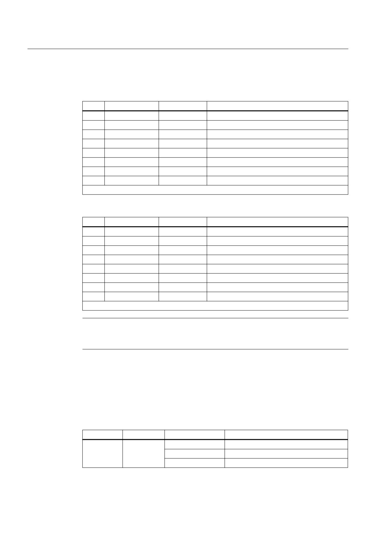
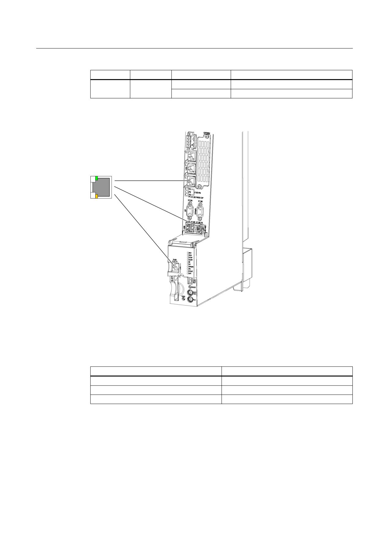
For diagnostic purposes, the RJ45 sockets are each equipped with a green and an orange
LED. This allows the following status information about the respective Ethernet port to be
displayed:
Table 7-11
LED displays of the Ethernet ports
Name
Color
Status
Meaning
Link
Green
Lights up green
Transfer rate 10 or 100 Mbit/s
Lights up orange
Transfer rate 1000 Mbit/s
off
No or faulty connection
NCU 7x0.3 PN, NCU 7x0.3B PN
56
Manual, 06/2014, 6FC5397-1EP40-5BA1
Connecting
7.6 Use of Ethernet interfaces
Name
Color
Status
Meaning
Activity
Orange
lit
Data exchange
off
No data exchange
Position of the Ethernet interfaces
;
3
31 ,( 23
;
3
31 ,( 1(7
;
3
31 ,(
Figure 7-5
Ethernet ports
Cable specification
Table 7-12
Cable specification for X120, X130, and X127
Characteristic
Version
Connector type
RJ45 socket
Cable type
Industrial Ethernet cable (CAT5)
Max. cable length
100 m
NCU 7x0.3 PN, NCU 7x0.3B PN
Manual, 06/2014, 6FC5397-1EP40-5BA1
57

Connecting
7.7 PROFINET
7.7
PROFINET
7.7.1
Application
Application
The following communication networks can be established via the PROFINET interface:
● PROFINET CBA:
Communication between controllers as components in distributed systems
● PROFINET IO
Communication between the PLC controller and field devices
Properties
The PROFINET interface X150 is equipped with an integrated 2-port switch and a TCP/IP
address for the 2 ports.
Pin assignment
Table 7-13
PROFINET interface, X150 ports 1, 2
Pin
Signal name
Signal type
Meaning
1
TXP
B
Transmit data +
2
TXN
B
Transmit data -
3
RXP
B
Receive data +
4
-
-
Reserved, do not use
5
-
-
Reserved, do not use
6
RXN
B
Receive data -
7
-
-
Reserved, do not use
8
-
-
Reserved, do not use
Signal type: B = bidirectional
Note
The PROFINET interface has what is known as autocrossing functionality, i.e. when required,
transmit and receive lines are switched over. Thus, no crossover cables are necessary.
NCU 7x0.3 PN, NCU 7x0.3B PN
58
Manual, 06/2014, 6FC5397-1EP40-5BA1
Connecting
7.7 PROFINET
LED displays
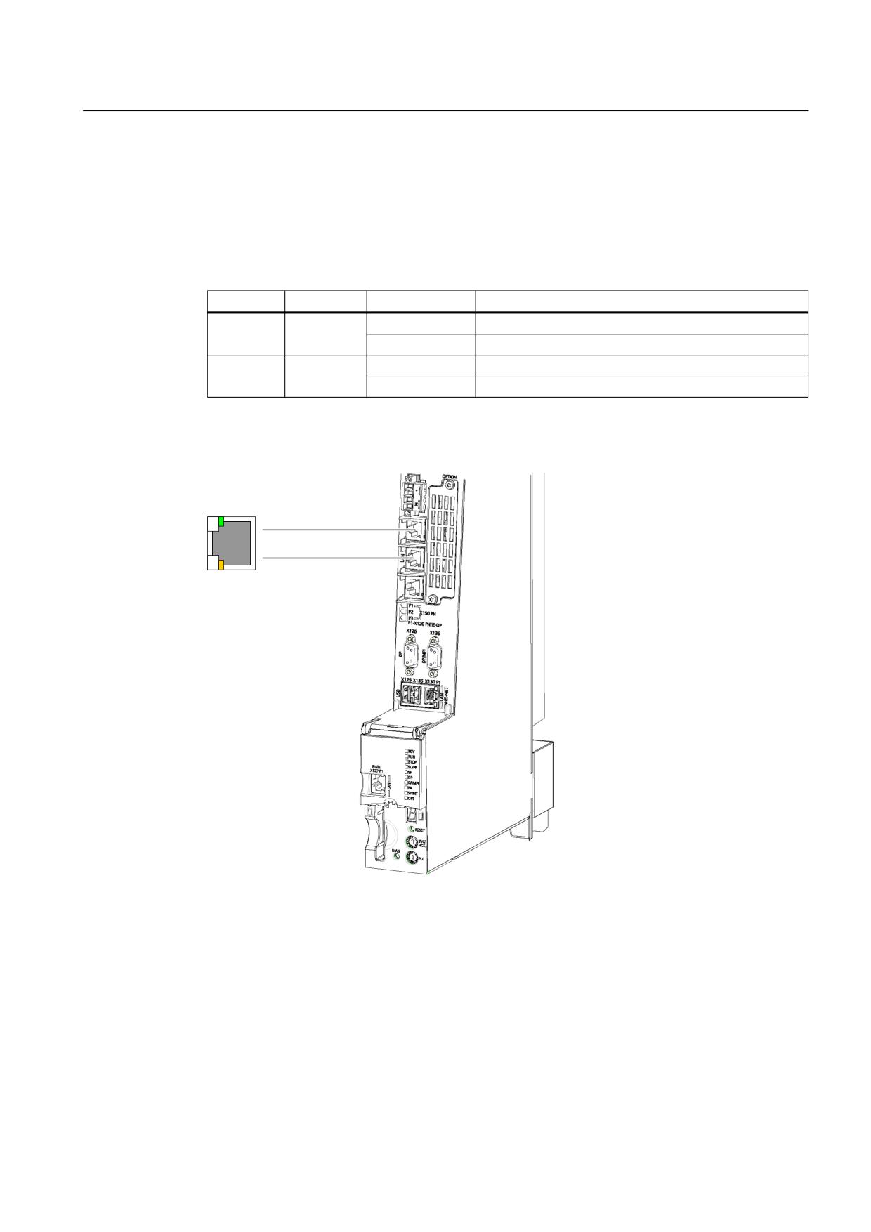
For diagnostic purposes, the RJ45 sockets are each equipped with a green and an orange
LED. This allows the following status information about the respective PROFINET port to be
displayed:
Table 7-14
PROFINET ports LED displays
Name
Color
Status
Meaning
Link
Green
lit
Transfer rate 100 Mbit/s
off
No or faulty connection
Activity
Orange
lit
Data exchange
off
No data exchange
Position of the PROFINET interface
;
3
;
3
Figure 7-6
PROFINET interface
NCU 7x0.3 PN, NCU 7x0.3B PN
Manual, 06/2014, 6FC5397-1EP40-5BA1
59
Connecting
7.7 PROFINET
Cable specification
For PROFINET, you always require a data transmission rate of 100 Mbit/s (Fast Ethernet) in
full duplex mode. For data transfer purposes, you can use twisted-pair copper cables (4-wire,
100Base-T).
Table 7-15
Cable specification for X150 ports 1, 2
Characteristic
Version
Connector type
RJ45 jack *)
Cable type
Industrial Ethernet cable (CAT5)
Max. cable length
100 m
*) Please use the Fast Connect connector as outlined in the chapter titled "PROFINET
cables (Page 60)".
7.7.2
PROFINET cables
Cable and connector types
Note
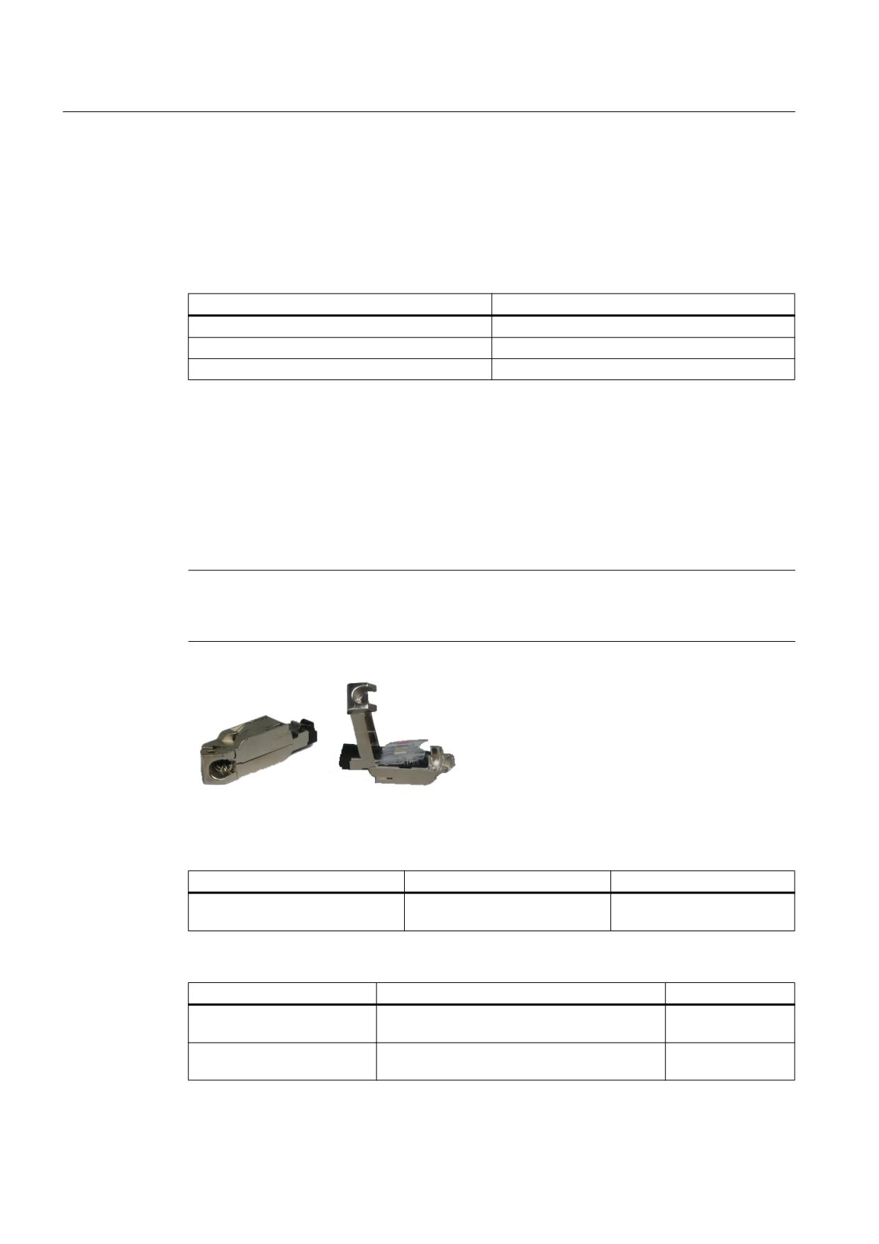
For connecting PROFINET to the NCU we recommend using a connector with a 145° cable
outlet (IE FC RJ45 plug 145).
Figure 7-7
RJ45 PN connector with a 145°cable outlet
Table 7-16
Connector types for PROFINET
Connector
Designation
Order number
IE FC RJ45 plug 145
RJ45 PN connector with angled
6GK1 901-1BB30-0AA0/
exit
6GK1 901-1BB30-0AB0
Table 7-17
Cable types for PROFINET
Cable
Designation
Order number
IE FC Cable GP 2 (Type A)
4-wire, shielded TP installation cable for IE FC
6XV1 840-2AH10
RJ45
IE FC Flexible Cable GP 2
4-wire, shielded flexible TP installation cable for
6XV1 870-2B
(Type A)
IE FC RJ45
NCU 7x0.3 PN, NCU 7x0.3B PN
60
Manual, 06/2014, 6FC5397-1EP40-5BA1

Connecting
7.7 PROFINET
Cable
Designation
Order number
IE FC Trailing Cable GP 2x2
4-wire TP installation cable for ground cable use
6XV1 870-2D
(Type C)
IE FC Trailing Cable 2x2
4-wire shielded TP installation cable for
6XV1 840-3AH10
(Type C)
connection to FC OUTLET RJ45, for ground
cable use
IE FC Marine Cable 2x2
4-wire shielded marine-certified TP installation
6XV1 840-4AH10
cable for connection to FC OUTLET RJ45
7.7.3
Preparing the twisted pair cables
Function
The IE FC RJ45 Plugs are used to install uncrossed 100 Mbit/s Ethernet connections up to
100 m without the use of patches. Crossed cables can also be installed by swapping the
transmit and receive pair in a plug.
Prerequisite
When you set up your PROFINET system, you can cut the AWG 22 twisted pair cable on-site
to the required length, strip it with the Fast Connect Stripping Tool (for Industrial Ethernet),
and fit the Industrial Ethernet FastConnect RJ-45 Plugs using the cut-and-clamp technique.
Proceed as follows
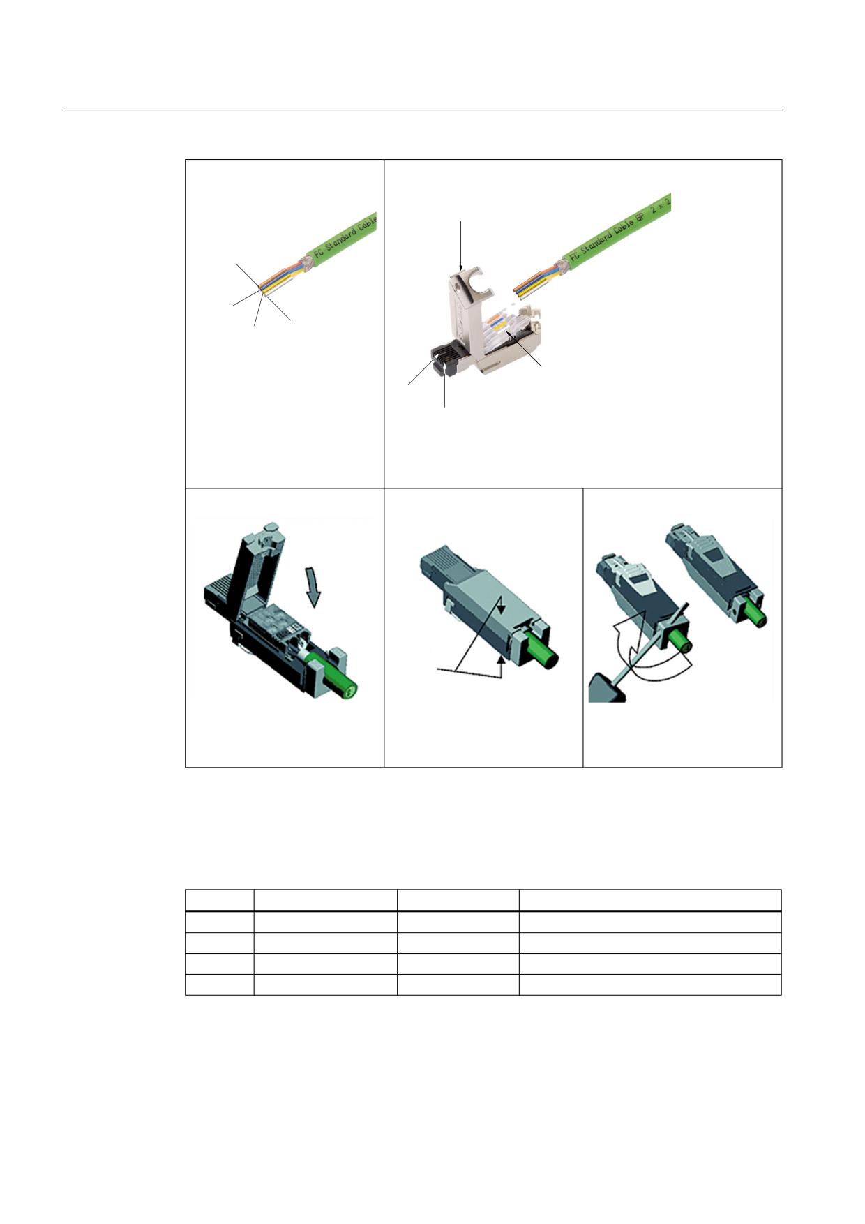
Contacting of the FC cable versions is simple and reliable with the 4 integrated insulation
displacement contacts.
● When the plug case is open, color markings on the contact cover make it easier to connect
the cores to the insulation piercing connecting devices. The user can check that contact
has been made correctly through the transparent plastic material of the contact cover.
● The stripped end of the cable is inserted in the raised insulation displacement terminals
and the terminals are then pressed down to ensure reliable contacting of the conductors.
NCU 7x0.3 PN, NCU 7x0.3B PN
Manual, 06/2014, 6FC5397-1EP40-5BA1
61
Connecting
7.7 PROFINET
①
②
&DVH FRYHU
RUDQJH
EOXH
ZKLWH
\HOORZ
&RQWDFW FRYHU
Strip the IE FC Cable 2x2 using
3LQ
a stripping tool and separate out
3LQ
the cores according to the color
coding on the contact cover of
the FC RJ45 plug.
Open the case cover of the FC RJ45 plug and insert the strands into
their respective end positions according to the color coding.
③
④
⑤
&DVH
FRYHU
Lower the contact cover so that
Close the case cover and press
Use a screwdriver to turn the
the strands are contacted.
down until it connects with the
snap ring 90°. This will ensure
plug case below.
tension and cable grip.
Assigning the installation cables to the pins on the IE FC RJ45 plug
Between the four individually colored wires of the IE FC RJ45 plug pins, the following
assignments are made:
Pin no.
Wire color
Signal name
Meaning
1
yellow
TX+
Transmit data +
2
Orange
TX-
Transmit data -
3
white
RX+
Receive data +
6
blue
RX-
Receive data -
NCU 7x0.3 PN, NCU 7x0.3B PN
62
Manual, 06/2014, 6FC5397-1EP40-5BA1
Connecting
7.7 PROFINET
Additional references
For more information, please refer to:
● The Industry Mall
● The Catalog IK PI
● The manual titled "SIMATIC NET Twisted Pair and Fiber-Optic Networks" (entry ID:
8763736).
7.7.4
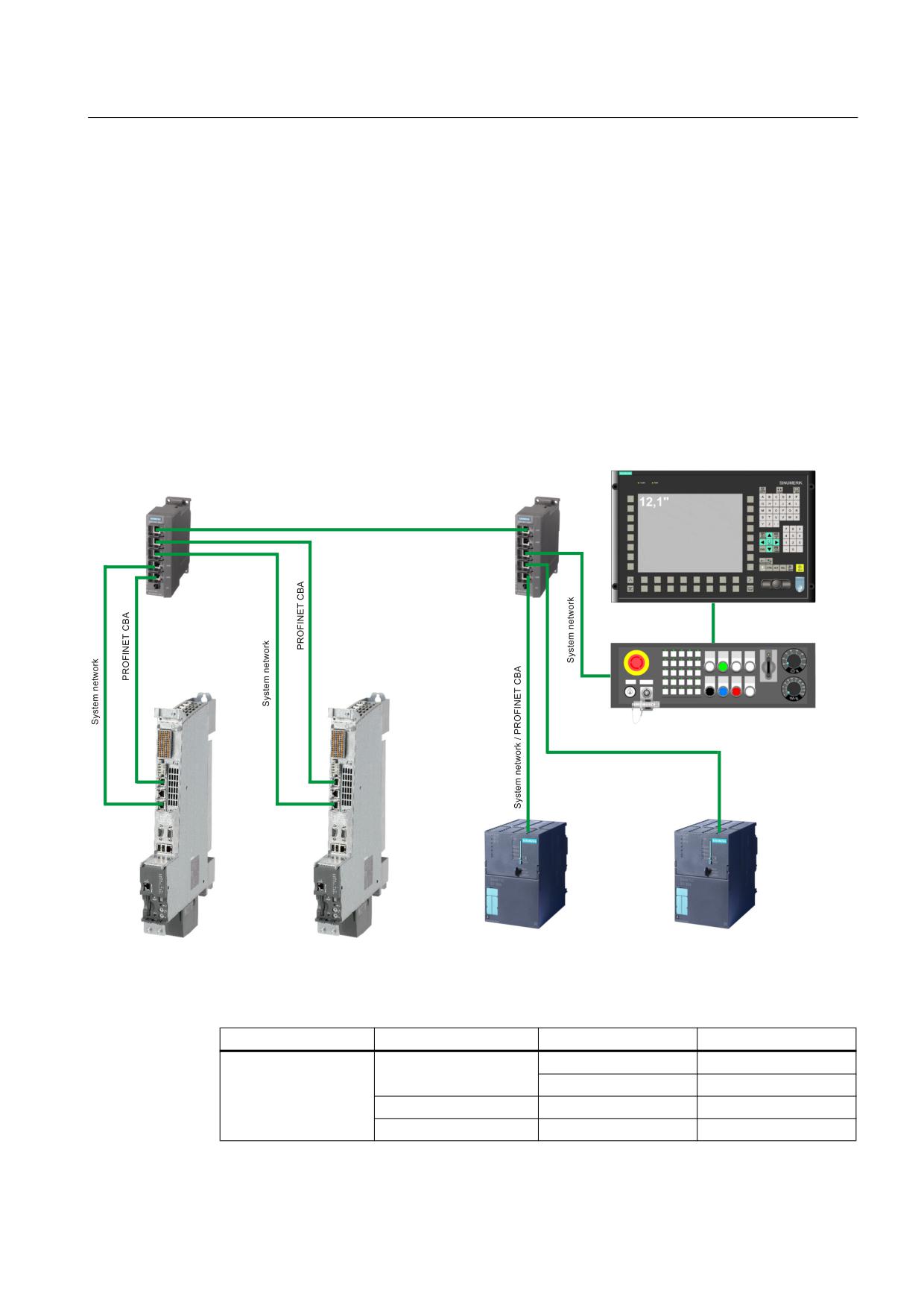
Example PROFINET CBA configuration
The following figure shows a typical system configuration with PROFINET CBA.
3&8
23
6FDODQFH ;
6FDODQFH ;
6\VWHP QHWZRUN
352),1(7 &%$
;
;
1&8
31
1&8
31
;
033
,(
6\VWHP QHWZRUN
352),1(7 &%$
;
;
3RUW
3RUW
&38
31 '3
&38
31 '3
;
;
&HQWUDO
8QLW
8QLW
8QLW
Figure 7-8
Example PROFINET CBA configuration
Station name
Module type
Interface
IP address
Central
NCU 730.3 PN
X120
192.168.200.1
X150 port 1
192.168.200.2
PCU 50.3
X501
192.168.200.5
MPP 483 IE
X20 DHCP server
192.168.200.50
NCU 7x0.3 PN, NCU 7x0.3B PN
Manual, 06/2014, 6FC5397-1EP40-5BA1
63

Connecting
7.8 PROFIBUS DP
Station name
Module type
Interface
IP address
Unit01
NCU 730.3 PN
X120
192.168.200.11
X150 port 1
192.168.200.12
Unit02
CPU 319-3 PN/DP
PN P1
192.168.200.22
Unit03
CPU 317-2 PN/DP
PN P1
192.168.200.32
7.8
PROFIBUS DP
7.8.1
Application
Connectable devices
The following devices can be connected to the PROFIBUS DP interfaces:
● Distributed I/O
● Drive units with PROFIBUS DP interface (standard slaves)
● S7 controllers with PROFIBUS DP interface
● PG/PC
Properties
● Isolated RS 485 interface
● Max. data rate 12 Mbits/s
● Supports master/slave operation
● PROFIBUS address is set via configuration
Note
In addition to the DP (distributed I/O) protocol, X136 can also transmit the MPI (multi point
interface) protocol (software-controlled).
Pin assignment for X126, X136
Table 7-18
PROFIBUS DP interface X126
Pin
Signal name
Signal type
Meaning
1
-
-
Reserved, do not use
2
M
VO
Ground to P24_SERV
3
1RS_DP
B
RS-485 differential signal
4
1RTS_DP
O
Request to send
5
M5EXT
VO
Ground to P5EXT
NCU 7x0.3 PN, NCU 7x0.3B PN
64
Manual, 06/2014, 6FC5397-1EP40-5BA1
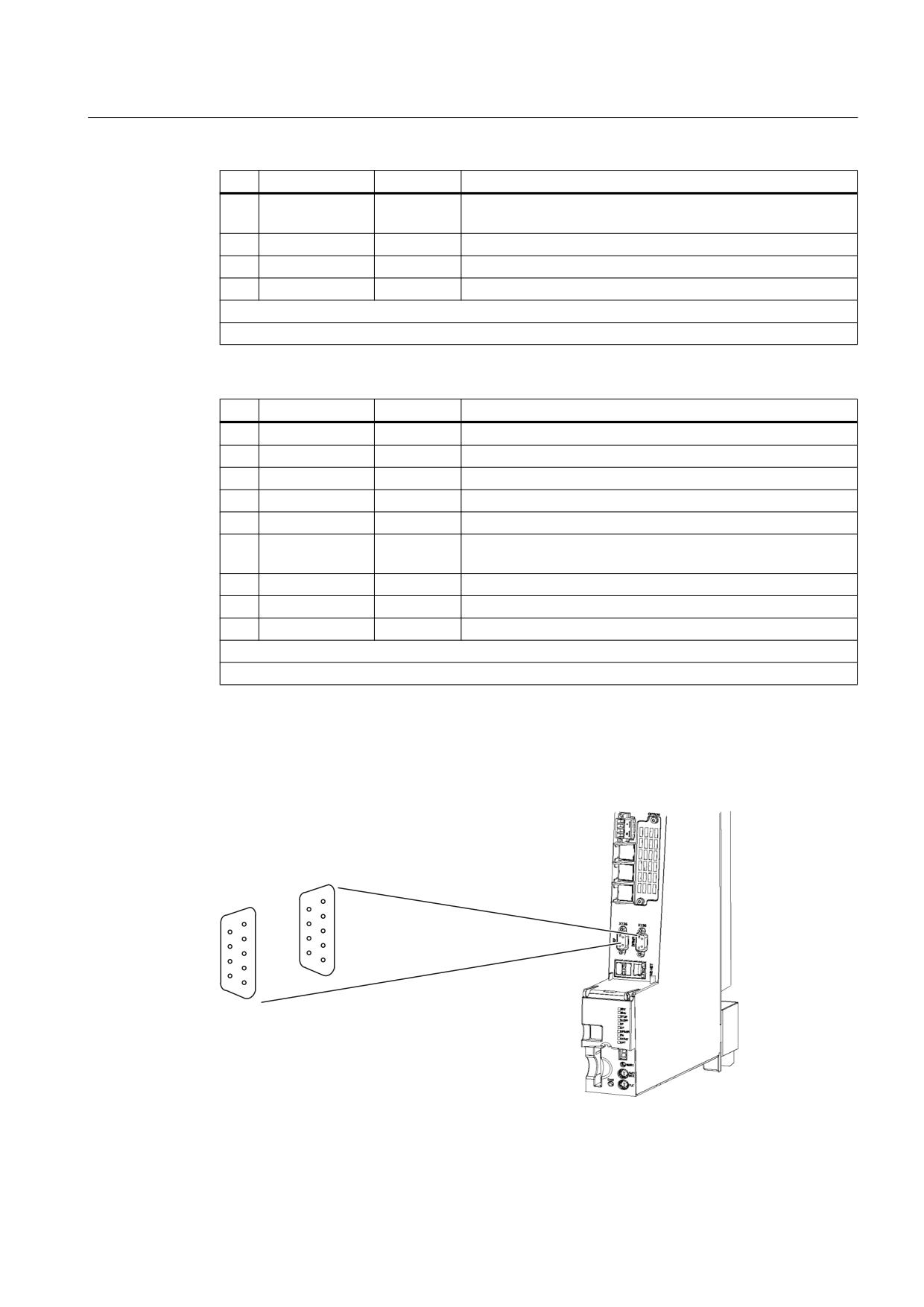
Connecting
7.8 PROFIBUS DP
Pin
Signal name
Signal type
Meaning
6
P5EXT
VO
5 V power supply for bus termination, external, short-circuit
proof
7
P24_SERV
VO
24 V for teleservice, short-circuit proof, 150mA maximum
8
1XRS_DP
B
RS-485 differential signal
9
-
-
Reserved, do not use
The 1P5 voltage is provided exclusively to supply the bus termination.
Signal type: VO = Voltage output (power supply) O = Output; B = Bidirectional
Table 7-19
PROFIBUS DP/MPI interface X136
Pin
Signal name
Signal type
Meaning
1
-
-
Reserved, do not use
2
M
VO
Ground to P24_SERV
3
2RS_DP
B
RS-485 differential signal
4
2RTS_DP
O
Request to send
5
1M5EXT
VO
Ground to 1P5EXT
6
1P5EXT
VO
5 V power supply for bus termination, external, short-circuit
proof
7
P24_SERV
VO
24 V for teleservice, short-circuit proof, 150mA maximum
8
2XRS_DP
B
RS-485 differential signal
9
-
-
Reserved, do not use
The 1P5 voltage is provided exclusively to supply the bus termination.
Signal type: VO = Voltage output (power supply) O = Output; B = Bidirectional
Position of connectors
The following figure shows the mounting position and the designation of the connector on the
module.
'3
'3 03,
;
;
Figure 7-9
PROFIBUS DP/MPI interfaces
NCU 7x0.3 PN, NCU 7x0.3B PN
Manual, 06/2014, 6FC5397-1EP40-5BA1
65
Connecting
7.8 PROFIBUS DP
7.8.2
PROFIBUS cables and connectors
Cable specification
The PROFIBUS cable is 2-wire, twisted, and shielded with defined technical data.
Table 7-20
Cable specifications for X126 and X136
Characteristics
Version
Connector type
9-pin SUB D connector
Cable type
PROFIBUS cable
Max. cable length
100 m at 12 Mbit/s
Table 7-21
Technical data for PROFIBUS cables
Characteristics
Values
Wave impedance
Approximately 135 to 160 Ω (f = 3 to 20 MHz)
Loop resistance
≤ 115 Ω/km
Effective capacitance
30 nF/km
Damping
0.9 dB/100 m (f = 200 kHz)
Permissible conductor cross section
0.3 mm2 to 0.5 mm2
Permissible cable diameter
8 mm + 0.5 mm
Cable lengths and data rate
The data rate determines the cable length of a subnet segment.
Table 7-22
Permitted cable length of a subnet segment for specific data rates
Data rate
Max. cable length of a segment (in m)
19.6 to 187.5 kbit/s
10001)
500 kbit/s
400
1.5 Mbit/s
200
3 to 12 Mbit/s
100
1)
With isolated interface
Longer cable lengths:
If you must realize greater cable lengths than permitted in one segment, you must use RS 485
repeaters. The maximum possible cable lengths between two RS 485 repeaters correspond
to the cable length of a segment. You can connect up to 9 RS 485 repeaters in series.
Note that an RS 485 repeater must be counted as a subnet node when determining the total
number of nodes to be connected. This is true even if the RS 485 repeater is not assigned its
own PROFIBUS address.
NCU 7x0.3 PN, NCU 7x0.3B PN
66
Manual, 06/2014, 6FC5397-1EP40-5BA1
Connecting
7.8 PROFIBUS DP
Connector features
The bus connector is used to connect the PROFIBUS cables to the PROFIBUS DP interfaces
(X126, X136), thus establishing a connection to additional nodes.
Only bus connectors with a 35° cable outlet should be used in order to ensure that the front
cover can be closed.
Note
Increased cabling space using PROFIBUS adapter connectors
The adapter connector is required if the bus cable is to be looped through at the left-hand
PROFIBUS interface (X126) of the NCU (2 PROFIBUS cables are connected at the
connector) and at the same time the Ethernet interface X120 is connected to a FastConnect
connector. When using the adapter plug, the PROFIBUS connector is higher, which creates
extra wiring space.
7.8.3
Connection components in PROFIBUS
Connection components
Individual nodes are connected by means of bus connectors and PROFIBUS cables.
Remember to provide a bus connector with a programming port at either end of the subnet.
This will give you the option of expanding the subnet if required, for example, for a programming
device.
Use RS 485 repeaters to connect segments or extend cable lengths.
Segments
A segment is a bus line between two terminating resistors. A segment may contain up to 32
nodes. In addition, a segment is limited by the permissible cable length, which varies according
to the transmission rate.
Terminating resistor
A cable must be terminated with its own surge impedance to prevent line disturbances caused
by reflections. Activate the terminating resistor at the first and last node on a subnet or segment.
The NCU must be either the first or the last node on the subnet.
Make sure that the stations to which the terminating resistor is connected are always supplied
with voltage during power-up and operation.
NCU 7x0.3 PN, NCU 7x0.3B PN
Manual, 06/2014, 6FC5397-1EP40-5BA1
67

Connecting
7.8 PROFIBUS DP
7.8.4
Rules for the laying of PROFIBUS cables
Laying of bus cables
During laying of the PROFIBUS cable, you must avoid:
● twisting
● stretching and
● squeezing
Supplementary conditions
During laying of the indoor bus cable, you must also consider the following supplementary
conditions (dO = outer diameter of the cable):
Table 7-23
Supplementary conditions for the laying of PROFIBUS cables
Features
Supplementary conditions
Bending radius for a single bend
80 mm (10xdO)
Bending radius (multiple times)
160 mm (20xdO)
Permissible temperature range for cable routing
-5 °C to +50°C
Temperature range for storage and stationary operation
-30°C to +65°C
Additional references
For length codes of prefabricated cables and additional information on PROFIBUS cables,
refer to "Electrical networks" in the PROFIBUS section of the IK PI catalog titled "Industrial
Communication and Field Devices".
7.8.5
Connecting PROFIBUS DP
Introduction
PROFIBUS cables are connected to the X126/X136 interface by means of a bus connector.
NCU 7x0.3 PN, NCU 7x0.3B PN
68
Manual, 06/2014, 6FC5397-1EP40-5BA1
Connecting
7.8 PROFIBUS DP
Wiring the bus connector
1. Proceed as follows to connect the bus connector:
2. Plug the bus connector into the corresponding interface on the NCU.
3. Screw the bus connector into place.
As the NCU is located at the start or end of a segment, you must switch on the terminating
resistor ("ON" switch setting).
7HUPLQDWLQJ UHVLVWRU
RQ
7HUPLQDWLQJ UHVLVWRU
RQ
VZLWFKHG RQ
VZLWFKHG RII
RII
RII
Figure 7-10 Terminating resistor switched on and off
Note
Make sure that the stations on which the terminating resistor is located are always supplied
with voltage during booting and operation.
7.8.6
Disconnecting stations from the PROFIBUS
Removing the bus connector
You can remove the bus connector with a looped-through bus cable from the PROFIBUS DP
interface at any time without interrupting data traffic on the bus.
NOTICE
Data exchange on the bus can be interrupted!
A bus segment must always be terminated with the terminating resistor at both ends. This is
not the case, for example, if the last node with a bus connector is de-energized. Because the
bus connector takes its voltage from the node, this terminating resistor is ineffective.
Make sure that the nodes at which the terminating resistor is connected are always energized.
7.8.7
Operating the X136 interface as MPI
Applications
The X136 interface can also be operated as an MPI interface instead of a PROFIBUS DP
interface. 187.5 kbit/s is the typical (preset) data rate. A maximum data rate of 12 Mbit/s can
be set to communicate with other CPUs. However, it should be noted that the maximum data
rate is not supported by all CPUs (e.g. smaller SIMATIC S7 CPUs).
NCU 7x0.3 PN, NCU 7x0.3B PN
Manual, 06/2014, 6FC5397-1EP40-5BA1
69
Connecting
7.8 PROFIBUS DP
The following list provides examples of when using MPI (multi-point interface) may prove
effective:
● If a PC/PG with an MPI is being used
● If an MPI-type handheld unit is being used
Operate MPI like PROFIBUS
The information on wiring the connector (terminating resistors) for PROFIBUS and the rules
on the laying of cables for PROFIBUS apply to this interface as well. When carrying out this
procedure, consult the relevant references.
Connector features
The bus connector is used to connect the MPI bus cable to the MPI (X136). This enables you
to establish connections to additional nodes (e.g. PG or SIMATIC S7-CPU). Only bus
connectors with a 35° cable outlet should be used in order to ensure that the front cover can
be closed.
MPI bus cable
The PROFIBUS cable specifications apply here as well. Please note the relevant information
on setting up an MPI network.
Setting up an MPI network
Keep in mind the following basic rules when setting up an MPI network:
● When using the interface as an MPI interface, it is not possible to arrange additional control
for a drive in isochronous mode or to connect distributed I/Os to this interface.
● An MPI bus line must be terminated at both ends. This is achieved by activating the
terminating resistor in the MPI connector in the first and last station and deactivating the
other terminating resistors.
● At least one terminator must be supplied with 5 V.
This means that an MPI connector with an activated terminating resistor must be connected
to a device that is switched on.
● Spur lines (cables leading from the bus segment to the node) should be as short as possible,
i.e. < 5 m in length. Unused spur lines should be removed wherever possible.
● Every MPI station must be connected to the bus first and then activated.
To disconnect the station, it must first be deactivated. Then, the station can be removed
from the bus.
● Maximum cable lengths:
-
200 m per bus segment
–
2000 m total length with RS 485 repeaters
NCU 7x0.3 PN, NCU 7x0.3B PN
70
Manual, 06/2014, 6FC5397-1EP40-5BA1
Connecting
7.9 Digital inputs/outputs
7.9
Digital inputs/outputs
7.9.1
DIO application
Connecting sensors and actuators
Digital inputs and outputs can be used to connect various sensors and actuators to the 14-pin
connectors X122 / X132 / X142 on the front panel. The interfaces are permanently assigned:
● X122 and X132: Drive
● X142: Control system
The following types of digital I/O are used:
● Digital inputs (isolated)
● Digital outputs
● Bidirectional digital inputs/outputs (only for drive terminals)
The assignment of I/Os to functions can be parameterized freely by the user. Special functions,
such as probe inputs (rapid inputs only) and cam outputs, can also be assigned to the inputs/
outputs.
The enables for the drive units and/or motors (Line Module, Motor Module) connected to the
NCU can be switched using the digital inputs.
Note
Terminal assignments
When commissioning the drive wizard, the digital inputs/outputs are correspondingly
preassigned functions.
For more information about terminal assignment, see:
● Commissioning Manual "IBN CNC: NCK, PLC, drive", Chapter "Communication interfaces
and terminal assignment"
● "Guidelines for machine configuration" System Manual, Chapter "Interfaces and their
terminal assignment"
Access to digital inputs/outputs
Note
The digital inputs/outputs of the drive terminals are updated in accordance with the set
PROFIBUS bus clock cycle of SINAMICS Integrated.
NCU 7x0.3 PN, NCU 7x0.3B PN
Manual, 06/2014, 6FC5397-1EP40-5BA1
71

Connecting
7.9 Digital inputs/outputs
Pin assignment
Table 7-24
X122 digital inputs/outputs
Pin
Signal name
Signal type
Meaning
1
DI0
I
Digital input 0
2
DI1
I
Digital input 1
3
DI2
I
Digital input 2
4
DI3
I
Digital input 3
5
DI16
I
Digital input 16
6
DI17
I
Digital input 17
7
G1
GND
Ground for DI0 - DI3, DI16, DI17 (isolated with respect to M)
8
M
GND
Ground
9
DI/DO8
B
Digital input/output 8 (rapid input)
10
DI/DO9
B
Digital input/output 9 (rapid input)
11
M
GND
Ground
12
DI/DO10
B
Digital input/output 10 (rapid input)
13
DI/DO11
B
Digital input/output 11 (rapid input)
14
M
GND
Ground
Signal type: B = Bidirectional; I = Input; GND = Reference potential (ground)
Table 7-25
X132 digital inputs/outputs
Pin
Signal name
Signal type
Meaning
1
DI4
I
Digital input 4
2
DI5
I
Digital input 5
3
DI6
I
Digital input 6
4
DI7
I
Digital input 7
5
DI20
I
Digital input 20
6
DI21
I
Digital input 21
7
G2
GND
Ground for DI4 - DI7 (functionally-separated relative to M)
8
M
GND
Ground
9
DI/DO12
B
Digital input/output 12 (rapid input)
10
DI/DO13
B
Digital input/output 13 (rapid input)
11
M
GND
Ground
12
DI/DO14
B
Digital input/output 14 (rapid input)
13
DI/DO15
B
Digital input/output 15 (rapid input)
14
M
GND
Ground
Signal type: B = Bidirectional; I = Input; GND = Reference potential (ground)
Table 7-26
X142 digital inputs/outputs
Pin
Signal name
Signal type
Meaning
1
-
-
Reserved, do not use
2
-
-
Reserved, do not use
NCU 7x0.3 PN, NCU 7x0.3B PN
72
Manual, 06/2014, 6FC5397-1EP40-5BA1
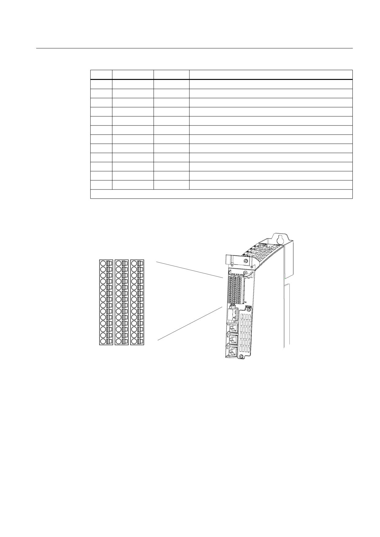
Connecting
7.9 Digital inputs/outputs
Pin
Signal name
Signal type
Meaning
3
IN/OUT0
B
Digital NC input 1
4
IN/OUT1
B
Digital NC input 2
5
M
GND
Ground
6
IN/OUT2
B
Digital NC input 3
7
IN/OUT3
B
Digital NC input 4
8
M
GND
Ground
9
IN/OUT4
B
Digital NC output 1
10
IN/OUT5
B
Digital NC output 2
11
M
GND
Ground
12
IN/OUT6
B
Digital NC output 3
13
IN/OUT7
B
Digital NC output 4
14
M
GND
Ground
Signal type: B = Bidirectional; GND = reference potential (ground)
Position of connectors
;
;
;
Figure 7-11 Digital inputs/outputs (interfaces X122, X132 and X142)
NCU 7x0.3 PN, NCU 7x0.3B PN
Manual, 06/2014, 6FC5397-1EP40-5BA1
73
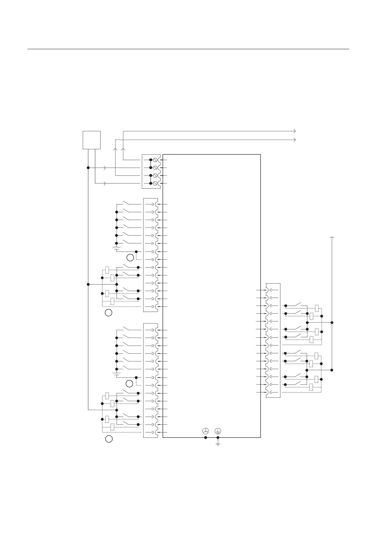
Connecting
7.9 Digital inputs/outputs
7.9.2
Block diagram
Block diagram
The following diagram shows the block diagram for the digital inputs/outputs of an NCU.
H[W
0
9
;
0
9
0
0
1&8 [
31
0
0
;
',
',
',
H[W
',
9
',
',
0
0
', '2
', '2
;
0
', '2
5HVHUYHG
', '2
5HVHUYHG
0
,1 287
,1 287
;
0
',
,1 287
',
,1 287
',
0
',
,1 287
',
,1 287
',
0
0
,1 287
0
,1 287
0
', '2
', '2
0
', '2
', '2
0
① Jumper open: Isolation for digital inputs
② can be parameterized as digital input/output
Figure 7-12 Block diagram for digital inputs/outputs
NCU 7x0.3 PN, NCU 7x0.3B PN
74
Manual, 06/2014, 6FC5397-1EP40-5BA1

Connecting
7.9 Digital inputs/outputs
Note
The fast digital inputs/outputs must be shielded.
7.9.3
Connecting digital inputs/outputs
Cable specification
Table 7-27
Cable specification at X122 / X132 / X142
Features
Version
Connector type
14-pin spring-loaded terminals
Connection option
0.2 to 1.5 mm2
Max. current carrying capacity
6 A
Max. cable length
30 m
Table 7-28
Connectable conductor cross-sections
Connectable
Rigid
0.2 to 1.5 mm2
conductor cross-
Flexible
0.2 to 1.5 mm2
sections
Flexible, with end sleeve without plastic sleeve
0.25 to 1.5 mm2
Flexible, with end sleeve with plastic sleeve
0.25 to 0.75 mm2
AWG / kcmil
24 to 16
Stripped length
10 mm
Tool
Screwdriver
0.4 x 2.0 mm
Note
To achieve optimum interference suppression, shielded cables must be used to connect
measuring inputs or BEROs.
Wiring digital inputs/outputs
1. Strip 10 mm of insulation from the wires.
2. Wire the digital inputs of the interface for connection of the sensors.
3. Wire the digital outputs of the interface for connection of the actuators.
4. Insert the cable into the corresponding spring-loaded terminal.
NCU 7x0.3 PN, NCU 7x0.3B PN
Manual, 06/2014, 6FC5397-1EP40-5BA1
75
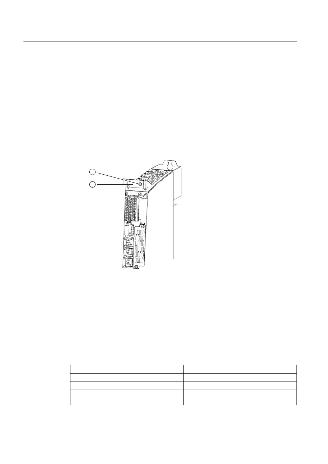
Connecting
7.9 Digital inputs/outputs
Using shielded cables
When using a shielded cable for the bidirectional inputs/outputs, the following options are
available for the shield connection:
1. Attach the cable shield to a grounded shielding bus immediately after the cable entry point
in the cabinet (strip the insulation off the cable for this purpose).
2. Continue routing the shielded cable as far as the module but do not make a connection to
the shield there.
Using a shield connection
1. Remove the fixing bracket of the shield connection.
2. Insert the cable and fasten the fixing bracket.
① Fixing bracket of the shield connection
② Torx screw M3/0.8 Nm
Figure 7-13 Shield support
7.9.4
Technical data
Digital inputs on X122/X132
Table 7-29
Technical data of digital inputs X122/X132
Parameters
Values
Voltage
-3 V to +30 V DC
Typical current consumption
9 mA at 24 V DC
Galvanic isolation
Reference potential is terminal G1 or G2
Signal level (including ripple)
High signal level: 15 V to 30 V
NCU 7x0.3 PN, NCU 7x0.3B PN
76
Manual, 06/2014, 6FC5397-1EP40-5BA1
Connecting
7.9 Digital inputs/outputs
Parameters
Values
Low signal level: -3 V to 5 V
Input delay (typ.)
L → H: 50 μs
H → L: 100 μs
Digital inputs/outputs at X122 / X132 / X142
Table 7-30
Technical data of the digital inputs/outputs of X122 / X132 / X142
Parameters
Values
As an input
Voltage
-3 V to +30 V DC
Typical current consumption
9 mA at 24 V DC
Signal level (including ripple)
High signal level: 15 V to 30 V
Low signal level: -3 V to 5 V
Input delay (typ.) of inputs / "rapid inputs"
L → H: 50 μs/5 μs
H → L: 100 μs / 50 μs
As an output
Voltage
24 V DC
Maximum load current per output
500 mA continuously short circuit-proof
Output delay (typ. / max.) 1)
L → H: 150 μs / 400 μs
H → L: 75 μs / 100 μs
Switching frequency
for resistive load: max. 100 Hz
for inductive load: max. 0.5 Hz
for lamp load: max. 10 Hz
max. lamp load
5 W
1)
Data for: Vcc = 24 V; load 48 Ω; High = 90 % Vout; Low = 10 % Vout
NOTICE
Ensuring the function of the digital inputs
An open input is interpreted as "low".
Only "rapid inputs" can be used as inputs for BEROs and probes.
Terminals G1 or G2 must be connected for the digital inputs to work. This can be done as
follows:
● Connect the ground reference of the digital inputs.
● A jumper to terminal M (note that these digital inputs are then no longer electrically
isolated).
Note
For a transient (brief) voltage interruption of the 24 V supply, the digital outputs are switched
inactive for this time.
NCU 7x0.3 PN, NCU 7x0.3B PN
Manual, 06/2014, 6FC5397-1EP40-5BA1
77
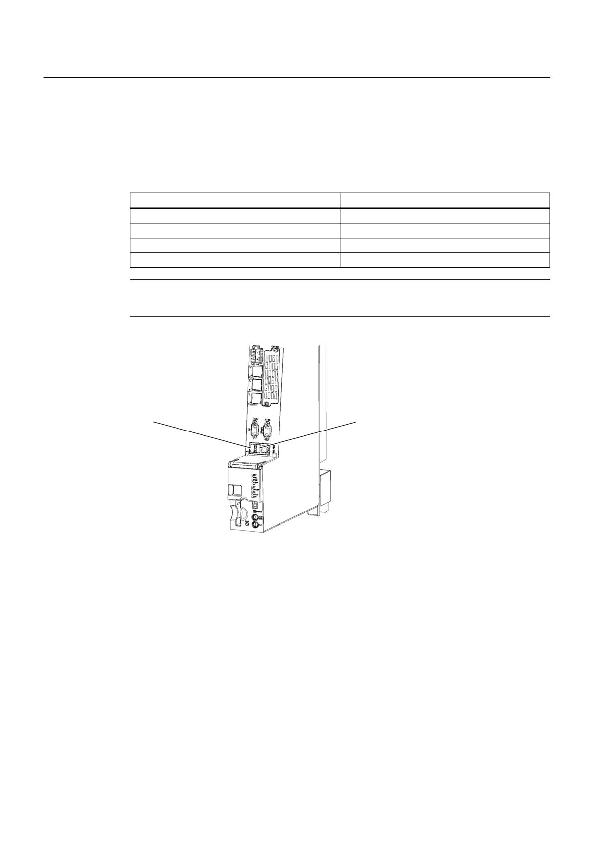
Connecting
7.11 Measuring sockets
7.10
USB
The USB interfaces are used exclusively for service purposes, correspond to the norm and
are, therefore, not described in detail here.
Table 7-31
Cable specification for X125 and X135
Characteristics
Versions
Connector type
Double USB socket - type A
Version
USB 2.0
Current carrying capacity
0.5 A per channel
Max. cable length
5 m
Note
The 5 V power supply is designed to be short-circuit proof.
;
;
Figure 7-14 Position of USB interfaces
7.11
Measuring sockets
Application
The measuring sockets are used to output analog signals. Any interconnectable signal can be
output on any measuring socket of the NCU.
● Max. output range of the test signal: 0 ... 5 V
● Measuring sockets have to be parameterized before use, as there is no default setting on
delivery.
NCU 7x0.3 PN, NCU 7x0.3B PN
78
Manual, 06/2014, 6FC5397-1EP40-5BA1
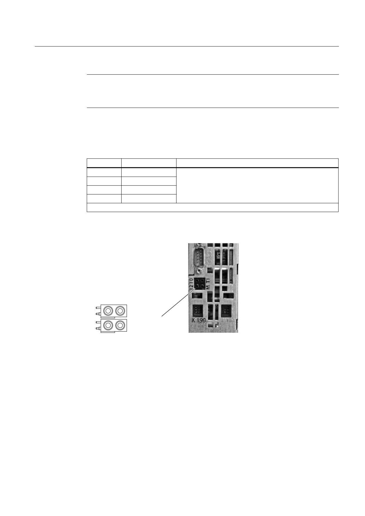
Connecting
7.11 Measuring sockets
Note
The measuring sockets should be used exclusively for servicing purposes.
The measurements may only be carried out by appropriately trained specialists.
Interface assignments
Table 7-32
Measuring sockets T0, T1, T2
Socket
Function
Technical data
T0
Test socket 1
Resolution: 8 bit.
T1
Measuring socket 2
Load current: max. 3 mA
T2
Measuring socket 3
continuous short-circuit-proof
M
Ground
The reference potential is terminal M
The measuring sockets are only suited for banana plugs with a diameter of 2 mm.
Test socket position
7
7
;
7
0
Figure 7-15 Arrangement of the measuring sockets on the lower side of the NCU
NCU 7x0.3 PN, NCU 7x0.3B PN
Manual, 06/2014, 6FC5397-1EP40-5BA1
79