SINUMERIK 840D sl Hardware. Manual (2011-2020) - page 14

Electronic handwheels
11
11.1
Description
Electronic handwheels are incremental encoders whose signals correspond to rotation of the
wheel actuated manually.
They are equipped with a magnetic latching mechanism that supports traversing with
incremental accuracy. The axis selected via the control can be positioned so that the axes are
parallel.
All handwheels have 100 I/U lines.
The electronic handwheels are available in several versions.
● They differ in terms of the interface and the size of the front plate.
● The cogging torque and the size of the adjustment wheel are adapted to the front plate.
● When required, the front panel can be removed.
An adapter set is available for installing the handwheels with central mounting in front panels
which are intended for the installation of handwheels with 3-hole mountings (see chapter
Accessories (Page 359)).
Note
The handheld handwheel is intended for machine level use, see Chapter at: "Handheld units"
→ "Handheld electronic handwheel". A magnet bracket and spiral cable can be found on its
housing.
The electronic handwheel with 24 V operating voltage and an HTL signal level is designed for
connecting to 24 V PLC counter modules.
Validity
The description applies to the following electronic handwheels:
Designation
Dimensions of front
Interface
Article number
panel (mm)
Encoder with setting wheel (large)
120 x 120
5 VDC, TTL *)
6FC9320-5DB01
Encoder with setting wheel
76.2 x 76.2
5 VDC, TTL *)
6FC9320-5DC01
Encoder without setting wheel (for central mounting)
without front panel
5 VDC, TTL *)
6FC9320-5DF01
Encoder with setting wheel
76.2 x 76.2
24 VDC, HTL
6FC9320-5DH01
Encoder with setting wheel (for central mounting)
without front panel
5 VDC, TTL *)
6FC9320-5DM00
*) according to RS 422 A (A = antivalent)
Machine control panels
Manual, 03/2016, 6FC5397-1AP40-5BA3
351
Electronic handwheels
11.1 Description
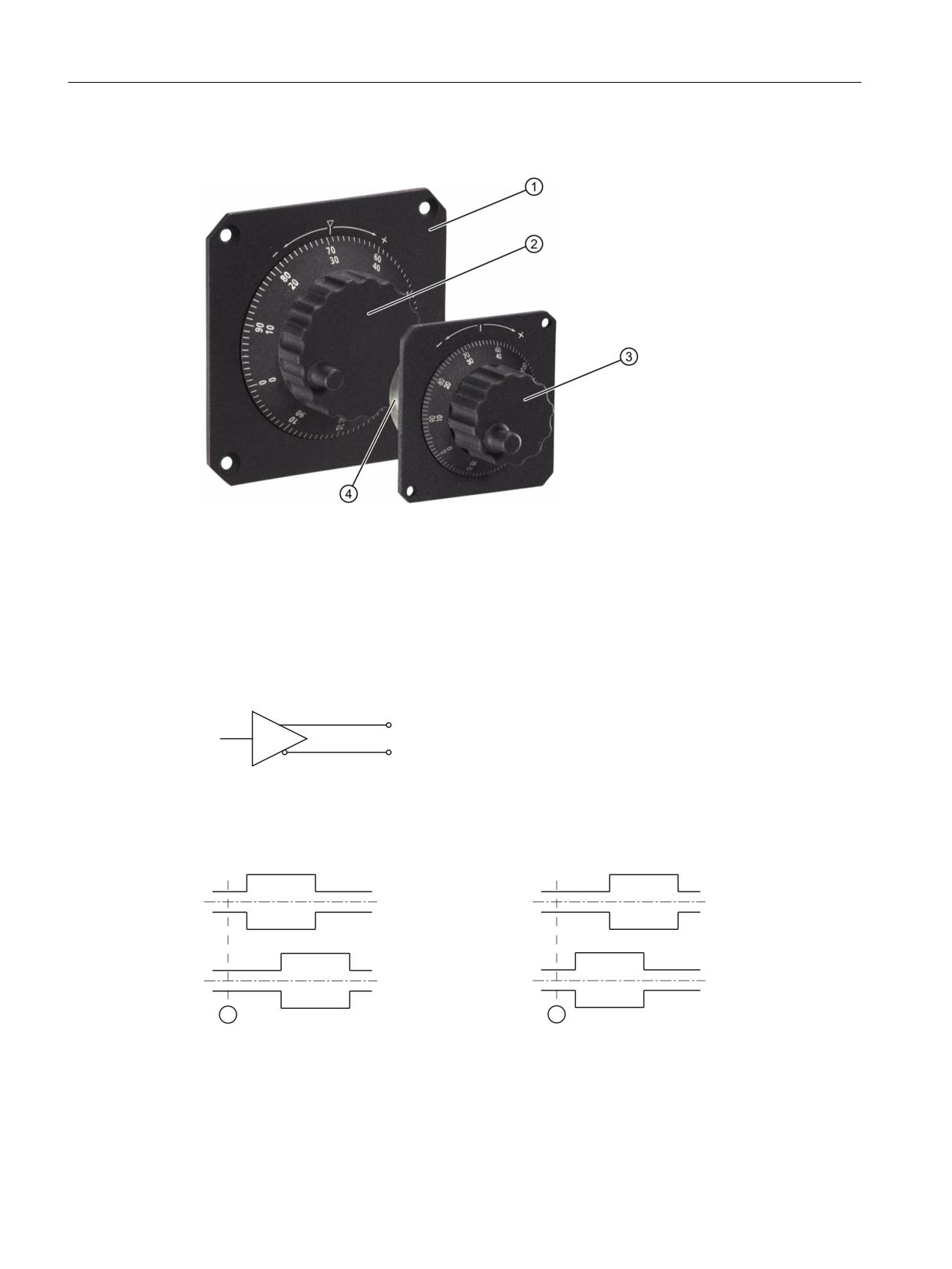
Diagram
① Front panel
② Setting wheel (large)
③ Setting wheel (small)
④ Encoder
Image 11-1 View of electronic handwheels
Principle output circuit
$%
&
$ %
Principle pulse diagram
CW rotation
CCW rotation
$
$
$
$
%
%
%
%
① Quiescent position
Machine control panels
352
Manual, 03/2016, 6FC5397-1AP40-5BA3
Electronic handwheels
11.2 Dimension drawings
11.2
Dimension drawings
11.2.1
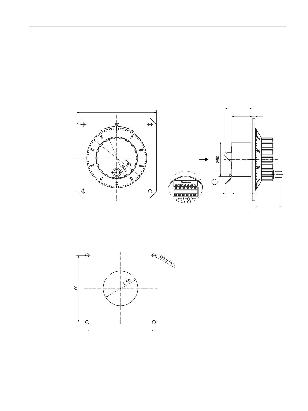
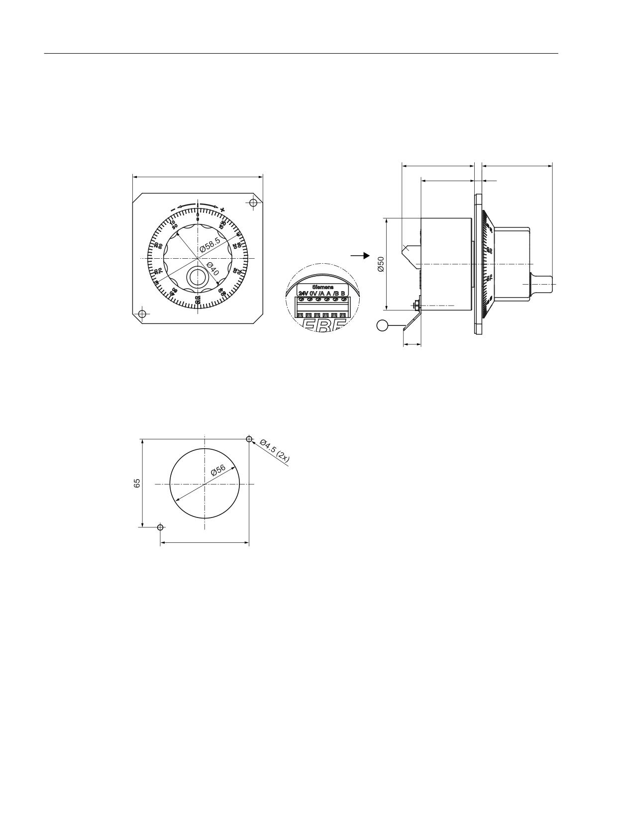
Encoder with 120 mm x 120 mm front panel, setting wheel (...-5DB01)
Front view and side view
༿
$
$
① Flat connector for push-on contacts 6.3 mm
Drilling pattern for mounting
To mount the handwheel, a cutout is required for the encoder and 4 mounting holes.
Mounting using 4 M5 screws. Tightening torque: 3 Nm
Machine control panels
Manual, 03/2016, 6FC5397-1AP40-5BA3
353
Electronic handwheels
11.2 Dimension drawings
11.2.2
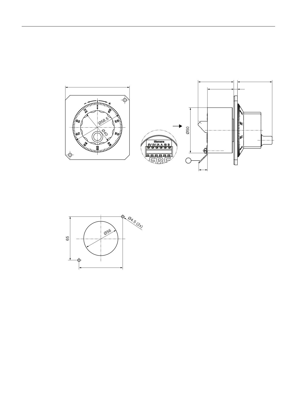
Encoder with front panel, 76.2 mm x 76.2 mm, setting wheel (...-5DC01)
Front view and side view
༿
$
$
① Flat connector for push-on contacts 6.3 mm
Drilling pattern for mounting
To mount the handwheel, a cutout is required for the encoder and 2 mounting holes.
Mounting using 2 M4 screws. Tightening torque: 1.8 Nm
Machine control panels
354
Manual, 03/2016, 6FC5397-1AP40-5BA3
Electronic handwheels
11.2 Dimension drawings
11.2.3
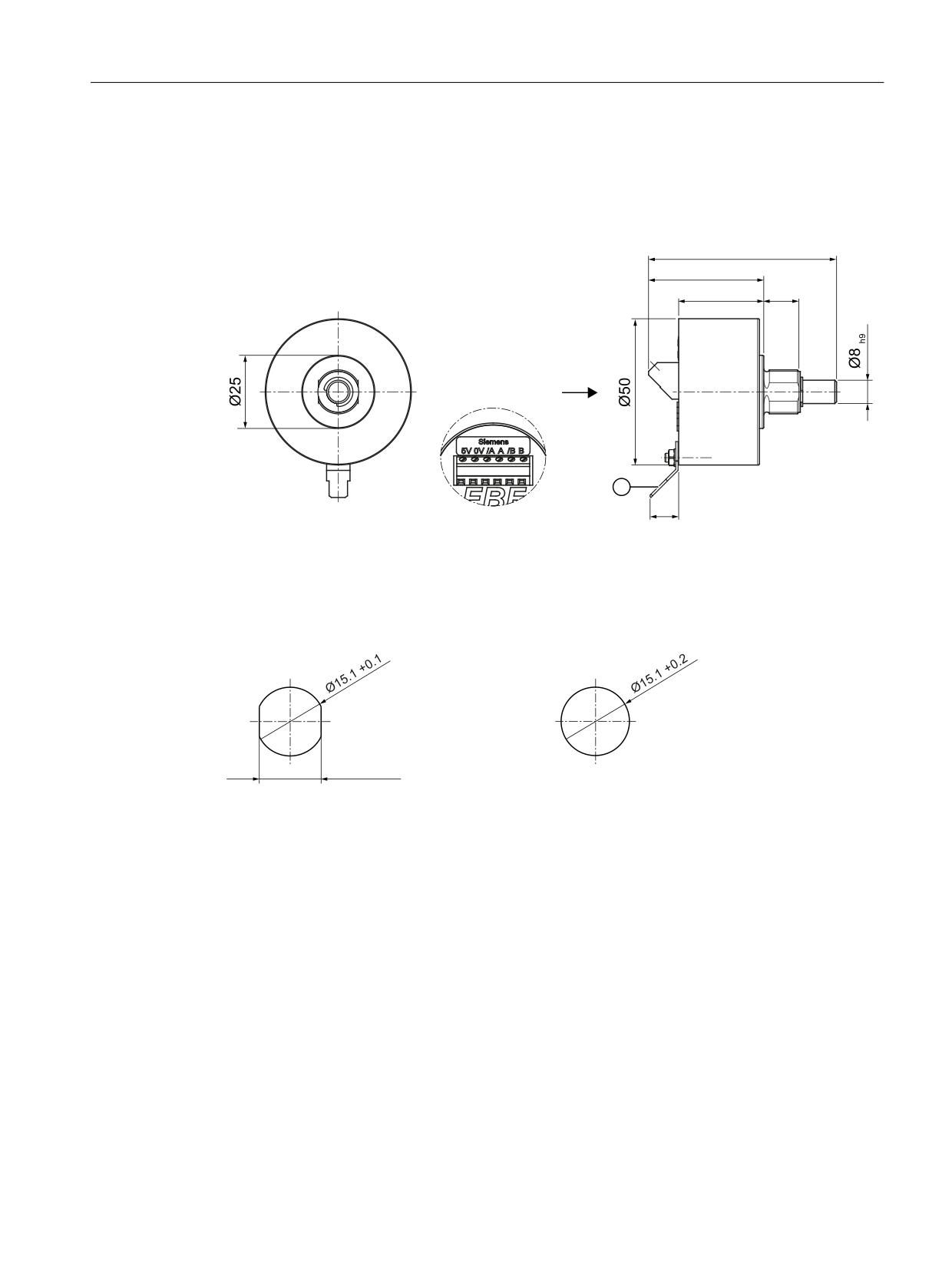
Encoder without front panel, without setting wheel (...-5DF01)
Front view and side view
$
$
① Flat connector for push-on contacts 6.3 mm
Switch panel cutout for mounting version
Cutout with twist protection
Cutout without twist protection
Central mounting with M15x1 nut, 5 Nm tightening torque, wrench size 17.
Machine control panels
Manual, 03/2016, 6FC5397-1AP40-5BA3
355
Electronic handwheels
11.2 Dimension drawings
11.2.4
Encoder with front panel, 76.2 mm x 76.2 mm, setting wheel (...-5DH01)
Front view and side view
༿
$
$
① Flat connector for push-on contacts 6.3 mm
Drilling pattern for mounting
To mount the handwheel, a cutout is required for the encoder and 2 mounting holes.
Mounting using 2 M4 screws. Tightening torque: 1.8 Nm
Machine control panels
356
Manual, 03/2016, 6FC5397-1AP40-5BA3
Electronic handwheels
11.2 Dimension drawings
11.2.5
Encoder without front panel, with setting wheel (...-5DM00)
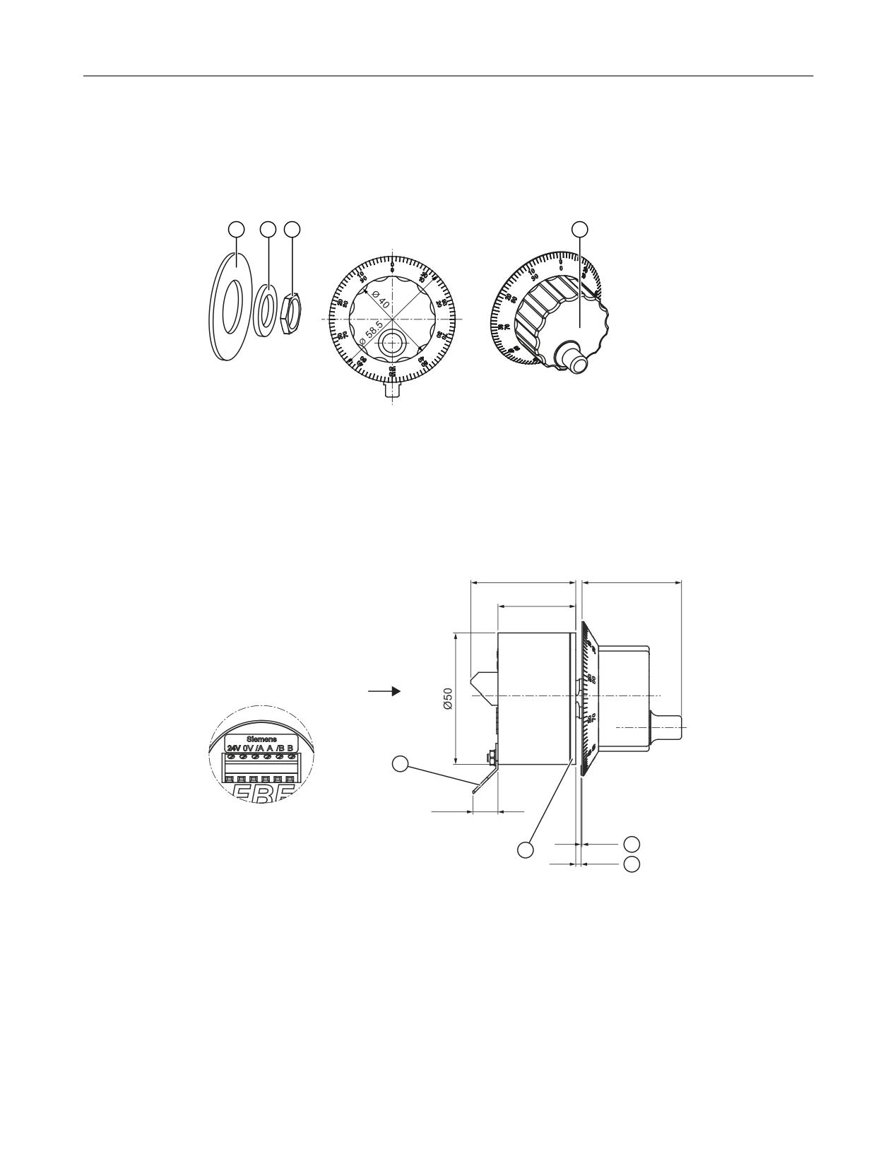
Individual parts
① Gasket/O-ring
② Washer
③ Nut M15x1
④ Rotary button with crank
Side view
$
$
① Flat connector for push-on contacts 6.3 mm
② Gasket
③ Recommended distance of 0.40 mm switch panel / rotary button
④ Switch panel thickness 2 to max. 6 mm
Machine control panels
Manual, 03/2016, 6FC5397-1AP40-5BA3
357
Electronic handwheels
11.4 Technical data
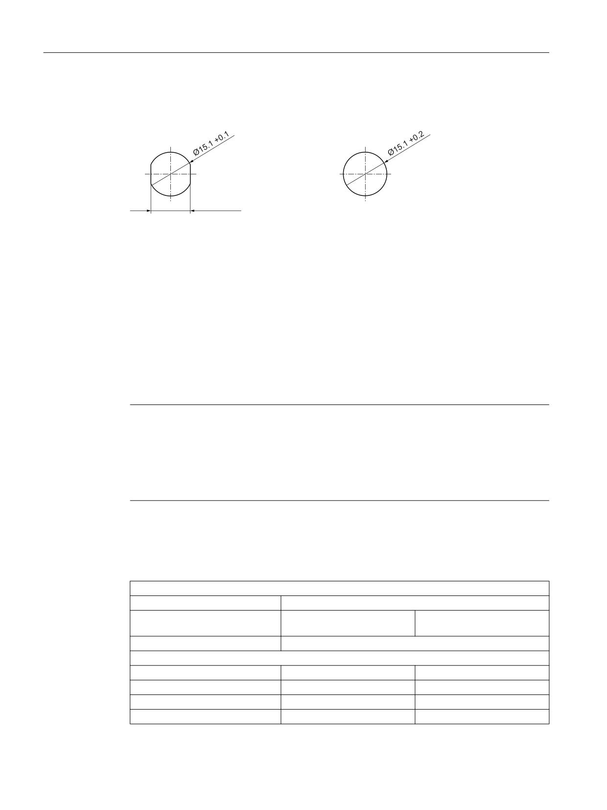
Switch panel cutout for mounting version
Cutout with twist protection
Cutout without twist protection
Central mounting with M15x1 nut, 5 Nm tightening torque, wrench size 17.
11.3
Connections
Connections for all versions of the electronic handwheel:
Connection:
6-pin screw-type terminal
Connectable conductor cross-sections:
AWG 22 … 14 or 0.3 mm2 … 2.5 mm2
with conductor end sleeves: max. 1.5 mm2
Tightening torque:
Max. 0.25 Nm
Flat connector 6.3 mm according to DIN 46244 (M3 - can be released).
Note
When a connected handwheel triggers pulses from its idle position or in the event of tiny
contacts, connect it so that the label is facing the wrong way.
Replace
- the wire of terminal A with the wire of terminal /A
- the wire of terminal B with the wire of terminal /B
11.4
Technical data
Safety
Safety class
I
Degree of protection according to
Front: IP65
Connection side: IP50
EN 60529
Approvals
CE
Electrical data
Type: 5 V
Type: 24 V
Rated voltage
5 VDC ± 10%
10 VDC - 30 V
Rated current (without load)
Max. 35 mA
Max. 10 mA
Rated current (full load)
Max. 55 mA
Max. 30 mA
Machine control panels
358
Manual, 03/2016, 6FC5397-1AP40-5BA3

Electronic handwheels
11.5 Accessories
Output signals
QB quadrature signals, electr. debounced
Output current
Max. 10 mA per output
Switching capacity
-
1.4 VA
Output frequency
Max. 2 kHz
Speed
Max. 1200 rpm
Number of pulses
100 I/U per track (A/B track)
Displacement of phase A to B
Typ. 90° electrical
Mechanical data
Weight
...-5DF01
Approx. 0.2 kg
...-5DM00
Approx. 0.3 kg
...-5DC01 / ...-5DH01
Approx. 0.42 kg
...-5DB01
Approx. 0.65 kg
Housing material
Steel / plastic
Max. distance to MCP / MPP / HAM
Max. 25 m
Actuating force
4 Ncm, with the exception of ...-5DB01: 8 Ncm
Max. tightening torque
5 Nm (via central mounting)
Service life
> 20x106 revolutions
Climatic and mechanical environ-
mental conditions
Condensation, spraying water and
Not permissible
ice formation
Operation
Storage and transport
Perm. ambient temperature
-20 ... 70° C
-40 ... 85° C
Rel. humidity
0 ... 80%
0 ... 80%
Vibration strength according to IEC
1g, 2-200 Hz, 1 oct/min, 133 min
68-1-5 (oscillation)
Shock resistance according to
10g, 11 ms
IEC 28-2-27
Interference immunity
According to EN 61000-6-2:2005
EMC
According to EN 61000-6-4:2007
RoHS conformity
Garanteed
11.5
Accessories
The following adapter set is available for installing the handwheels with central mounting in
front panels which are intended for the installation of handwheels with 3-hole mountings:
Component
Description
Number
Article number
Adapter set
For installation with 3-hole mounting
1
6FC9320-5DN00
Machine control panels
Manual, 03/2016, 6FC5397-1AP40-5BA3
359
Electronic handwheels
11.5 Accessories
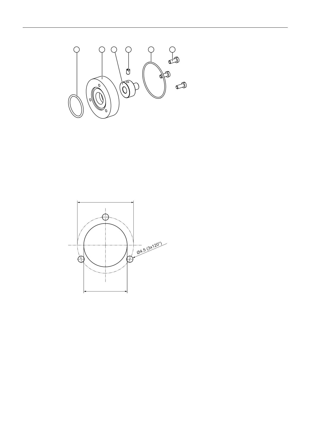
① O-ring
② Adapter ring
③ Axle adapter
④ Threaded stud
⑤ O-ring
⑥ Cylinder head screw DIN 84 M4x10 (3x)
Image 11-2 Components of adapter set
To mount the adapter set, a cutout and three mounting holes are required.
s
Image 11-3 Drilling pattern for mounting
Mounting using three M4 screws. Tightening torque: 1.8 Nm
Machine control panels
360
Manual, 03/2016, 6FC5397-1AP40-5BA3
Rotary override switch
12
12.1
Description
Although some of the rotary override switches described in this chapter already belong to the
standard scope of an MCP/MPP, they can also be provided as an upgrade or installed in their
own operator panels.
Note
The connection to an MCP/MPP is via X30/X31.
Validity
The description applies to the following rotary override switches
Type
Category
Article number
Override spindle / rapid traverse
Electronic, 1x16G, T=24
6FC5247-0AF12-1AA0
Override feed / rapid traverse
Electronic, 1x23G, T=32
6FC5247-0AF13-1AA0
Override feed / rapid traverse
Electronic, 1x29G, T=32
6FC5247-0AF14-1AA0
Override spindle / rapid traverse
Mechanical, 1x16G, T=24
6FC5247-0AF12-0AA0
Override feed / rapid traverse
Mechanical, 1x23G, T=32
6FC5247-0AF13-0AA0
Features
● Gray-code coding
● Central attachment
● Connection via ribbon cable with plug connector
Pin
Meaning
Electronic variants
Mechanical variants
1
Not connected
Not connected
2
Not connected
Not connected
3
Ground
Ground
4
Not connected
Vcc (4.75 ... 5.5 V)
5
Vcc (4.75 ... 5.5 V)
Not connected
6
Weighting factor 16
Weighting factor 16
7
Weighting factor 8
Weighting factor 8
8
Weighting factor 4
Weighting factor 4
9
Weighting factor 2
Weighting factor 2
10
Weighting factor 1
Weighting factor 1
Machine control panels
Manual, 03/2016, 6FC5397-1AP40-5BA3
361
Rotary override switch
12.2 Mounting
12.2
Mounting
12.2.1
Dimension drawings
s
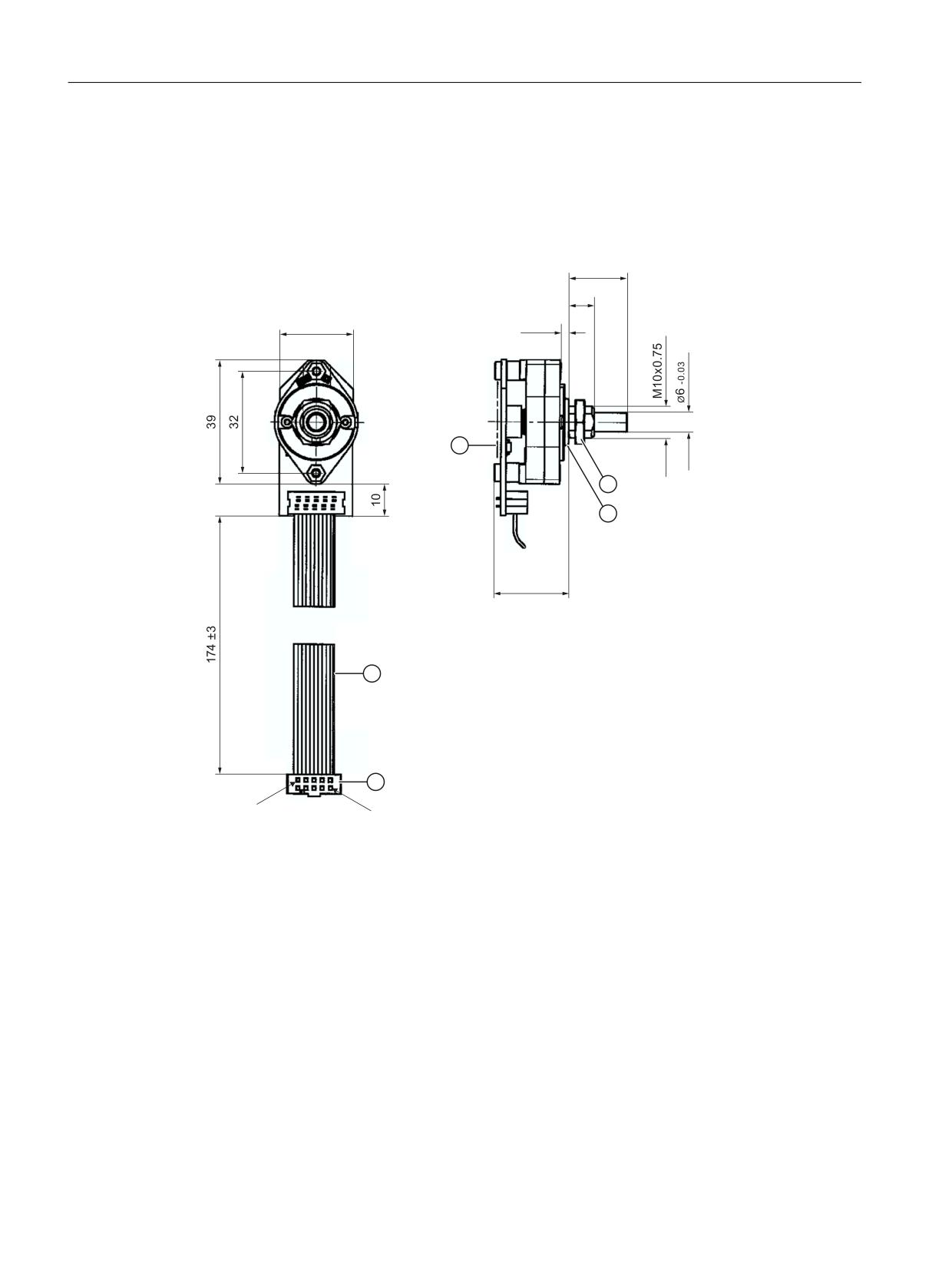
① Marking
② Plug connector
③ Type plate
④ Fastening nut with SW 14 (width across flats)
⑤ O ring 12.2 x 1.3
Image 12-1 Dimension drawing for electronic rotary override switch
Machine control panels
362
Manual, 03/2016, 6FC5397-1AP40-5BA3
Rotary override switch
12.2 Mounting
s
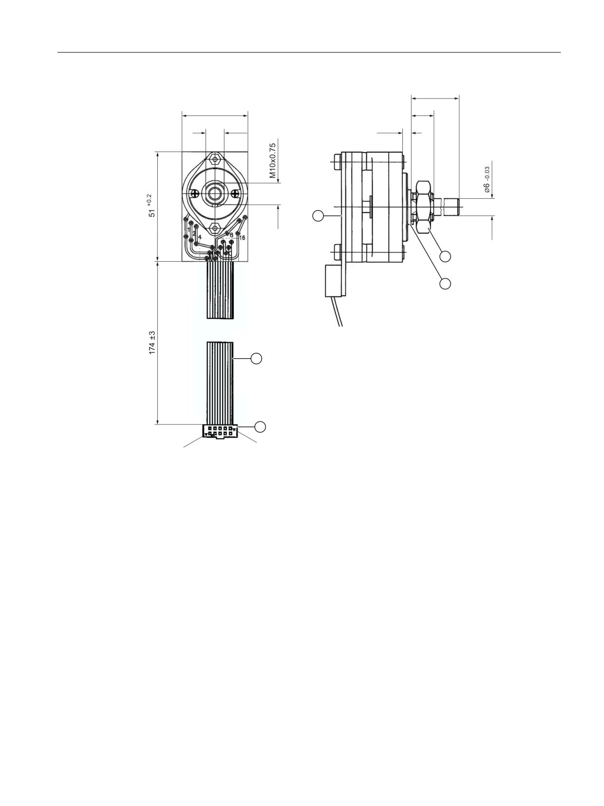
① Marking
② Plug connector
③ Type plate
④ Fastening nut with SW 14 (width across flats)
⑤ O ring 12.2 x 1.3
Image 12-2 Dimension drawing for mechanical rotary override switch
Machine control panels
Manual, 03/2016, 6FC5397-1AP40-5BA3
363
Rotary override switch
12.2 Mounting
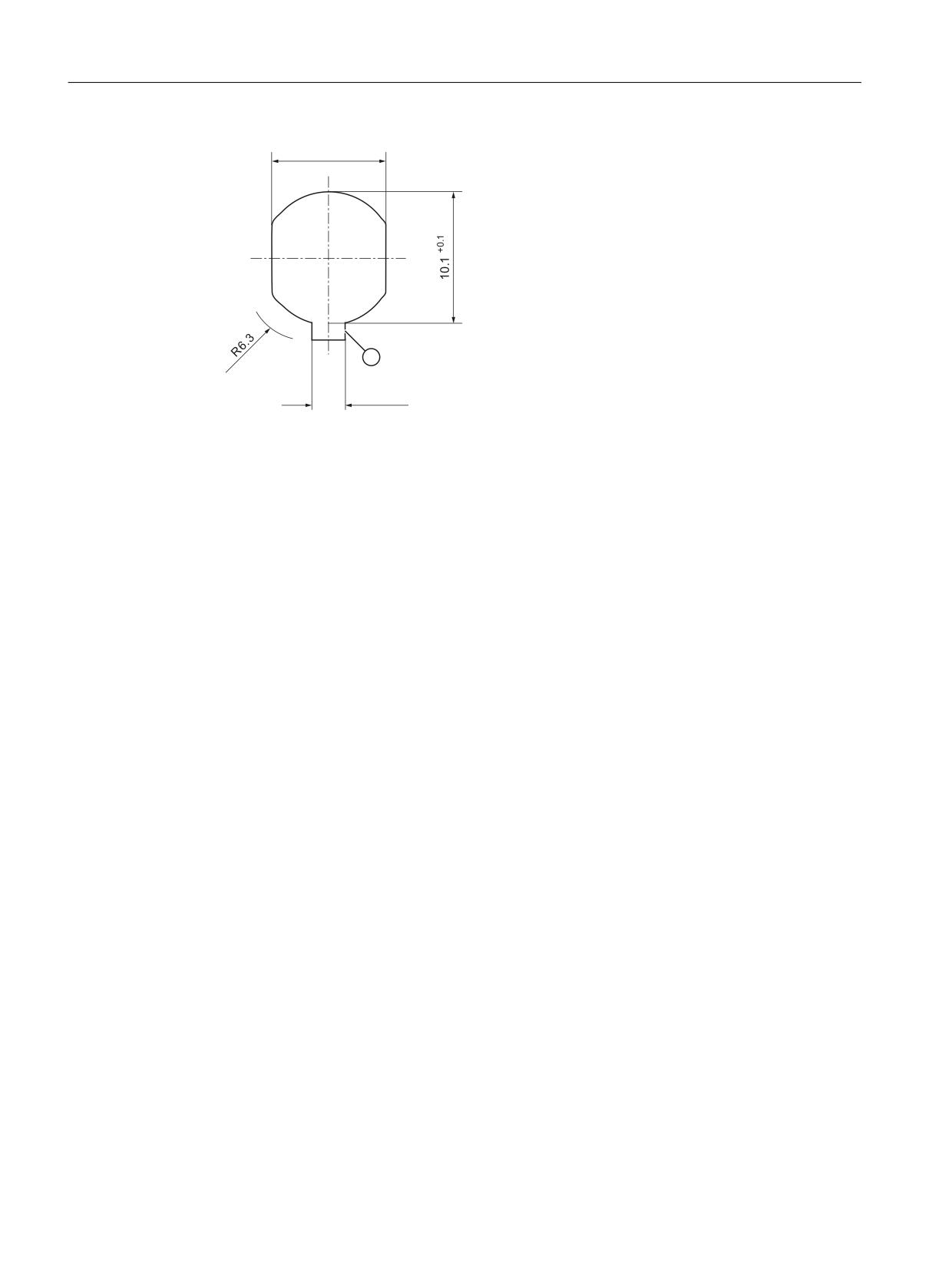
① Anti-twist protection
Image 12-3 Operator panel cutout for fastening the rotary override switch
12.2.2
Replacing the rotary switch
Removal of a rotary switch
1. Lever the cap (3) off the rotary knob (2) (snap-on connection!).
2. Remove the nut of the collet (1) with a wrench (width 10).
3. Remove the entire rotary knob (2).
4. Remove the fastening nut (5) on the shaft of the rotary switch (4) with a wrench (width 14).
5. Remove the connector on the end of the rotary switch cable from the slot.
6. Remove the rotary switch.
Machine control panels
364
Manual, 03/2016, 6FC5397-1AP40-5BA3
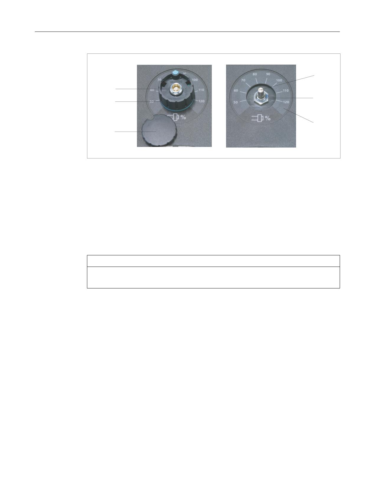
Rotary override switch
12.2 Mounting
(1)
Nut of the collet
(2)
Rotary knob
(3)
Cap
(4)
Rotary switch shaft
(5)
Fastening nut
(6)
Scale
Image 12-4 Removal of a rotary switch
Installation of a rotary switch
NOTICE
Damage to the rotary switch during the fastening
It is essential to use the correct tightening torques shown below.
1. Push the O-ring (1) onto the shaft of the new rotary switch as a seal.
2. Insert the rotary switch into the front cutout so that pressure is applied to the O-ring.
3. Tighten the fastening nut (4) on the shaft of the rotary switch from the front with a wrench
(width 14) (tightening torque: 3 Nm).
4. Connect the arrow ring (3) and the rotary knob (5).
5. Slide both parts onto the shaft of the rotary switch.
6. Align the arrow point on the ring with position "0" on the scale.
7. Tighten the collet nut of the rotary knob by hand and using a torque spanner with 2 Nm
torque.
8. Place the cap (2) on the rotary knob and snap it into position.
9. Fold and fasten the connecting cable (7) as shown in the figure on the right.
Machine control panels
Manual, 03/2016, 6FC5397-1AP40-5BA3
365
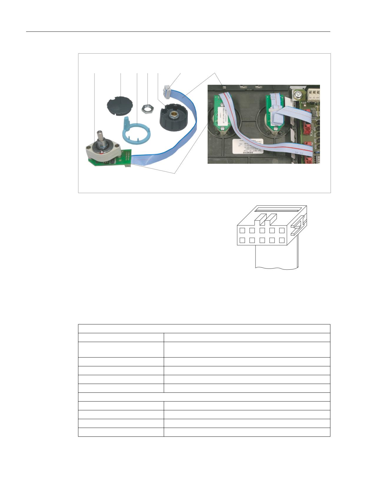
Rotary override switch
12.3 Technical data
(1)
O-ring
Detail diagram of the connector
(2)
Cap
(3)
Arrow ring
(4)
Fastening nut
(5)
Rotary knob
(6)
Connector (see detail diagram)
(7)
Connecting cable
(8)
Connection PCB
Image 12-5 Installation of a rotary switch
12.3
Technical data
Electrical data
Power supply (Vcc)
4.75 ... 5.5 VDC ± 100 mV
Power consumption typical/maxi-
25 mA / 75 mA (all outputs loaded)
mum
Reverse polarity protection
Up to 12 V
Short-circuit protection
limited short-circuit protection (max. 50 ms)
Output level
"low" < 0.6 V; "high" > Vcc - 1 V
Output current
Max. 10 mA
Mechanical data
Activation torque
approx. 9 Ncm
Stop strength
2.5 Nm
Starting torque
max. 500 Nm
Dust protection
Sensor range protected with a cap
Machine control panels
366
Manual, 03/2016, 6FC5397-1AP40-5BA3

Rotary override switch
12.3 Technical data
Service life
50,000 cycles
Ambient temperature
Operation: -25° C ... +85° C
Storage: -40° C ... +135° C
Vibration strength
1g; 2 - 200 Hz; 1 octave/min, 133 min according to IEC 68-2-6
Shock/impact strength
10g, 11 ms according to IEC 28-2-27
Machine control panels
Manual, 03/2016, 6FC5397-1AP40-5BA3
367
Rotary override switch
12.3 Technical data
Machine control panels
368
Manual, 03/2016, 6FC5397-1AP40-5BA3
Index
C
H
COM board
Handwheel
MCP 310, 55, 56
MCP 310C PN, 12
MCP 483, 122, 123
MCP 483, 120, 122
MPP 483, 300
MCP 483C PN, 84
D
K
DIP switch
Key covers
MCP 483, 122
MCP 310C PN, 11, 27
Direct keys
MCP 483C PN, 83, 97
MPP 310 IE H, 181
Key-operated switch
MPP 483, 307
MCP 310, 53, 54
MPP 483 IE, 235
MCP 310 PN, 29, 31, 42
DP slave MPP
MCP 310C PN, 11
MPP 483, 308
MCP 483, 120
Keyswitch
MCP 310, 73
E
MCP 483, 119, 140
MCP 483 PN, 100, 112
EKS identification system
MCP 483C PN, 83
MPP 310 IE H, 147
MPP 483, 251
MPP 483 IE, 195
L
Emergency stop button
MCP 310C PN, 26
LEDs
MPP 483, 305
MCP 483, 122
Emergency Stop button
MCP 310, 54, 72
MCP 310 PN, 30, 31, 41, 42
M
MCP 483, 119, 120, 139
MCP 310
MCP 483 PN, 100, 111
COM board, 55, 56
MCP 483C PN, 83, 96, 97
Dimension drawing, 61
Emergency stop circuit
Dimensions, 72
MCP 483 PN, 102
Emergency Stop button, 54, 72
MCP 483C PN, 86
Key-operated switch, 53, 54
Ethernet
Keyswitch, 73
MCP 310C PN, 11
Mounting position, 61
MCP 483C PN, 84
Power consumption, 72
Expansion panel, 245
PROFIBUS DP, 57, 124
Extension keys
Rotary switch, 53
MPP 310 IE H, 180
Slide-in labels, 53, 73, 74
MPP 483, 306
Slots, 54
MPP 483 IE, 234
MCP 310 PN
Dimension drawing, 38
Dimensions, 41
Machine control panels
Manual, 03/2016, 6FC5397-1AP40-5BA3
369
Index
Emergency Stop button, 30, 31, 41, 42
Power consumption, 96
Key-operated switch, 29, 31, 42
Rotary switch, 97
Mounting position, 39
MPP 310 IE H
Power consumption, 41
Actuation elements, 154
Rotary switch, 29
Anode connection for LEDs, 171
Slide-in labels, 29, 42, 43
COM board IE, 154
Slots, 30, 31
Dimensions, 184
MCP 310C PN
Direct keys, 181
Dimensions, 26
EKS identification system, 147
Emergency stop button, 26
Extension keys, 180
Ethernet, 11
Lamps, 154
Handwheel, 12
Mounting position, 170
Key covers, 11, 14, 27
Power consumption, 184
Key-operated switch, 11
Signaling lamps, 179
Power consumption, 26
Slide-in labels, 147
MCP 483
Software Version, 182
COM board, 122, 123
System configuration, 149
Dimension drawing, 127
MPP 483
Dimensions, 139
Actuation elements, 267
DIP switch, 122
Anode connection for LEDs, 293
Emergency Stop button, 119, 120, 139
Coding switch S3, 300
Equipotential bonding conductor, 123
COM board, 268, 300
Handwheel, 120, 122
Dimensions, 315
Key symbols, 141
Direct keys, 307
Key-operated switch, 120
DP slave MPP, 308
Keyswitch, 119, 140
EKS identification system, 251
LEDs, 122
Emergency stop button, 305
Mounting position, 128
Extension keys, 306
Power consumption, 139
GSD file, 308
Slide-in labels, 119, 140, 141
Lamps, 267
Slots, 120
Mounting position, 292
MCP 483 PN
Power consumption, 315
Dimension drawing, 109
PROFIBUS DP, 285
Dimensions, 111
PROFIBUS parameters, 310
Emergency Stop button, 100, 111
Signaling lamps, 305
Emergency stop circuit, 102
Slide-in labels, 251
Key symbols, 113
Special versions, 252
Keyswitch, 100, 112
Standard version, 251
Mounting position, 109
Standard version, extended, 251
Power consumption, 111
Supplementary elements, 253
Slide-in labels, 99, 112, 113
System configuration, 254
MCP 483C PN
MPP 483 IE
Dimension drawing, 93
Actuation elements, 207
Dimensions, 96
Anode connection for LEDs, 226
Emergency Stop button, 83, 96, 97
COM board, 207
Emergency stop circuit, 86
Customer keys, 208
Ethernet, 84
Dimensions, 238
Handwheel, 84
Direct keys, 235
Key covers, 83, 97
EKS identification system, 195
Keyswitch, 83
Extension keys, 234
Mounting position, 94
Lamps, 207
Mounting position, 225
Machine control panels
370
Manual, 03/2016, 6FC5397-1AP40-5BA3
Index
Power consumption, 238
Slide-in labels, 195
Software Version, 236
Special versions, 195
Standard version, 195
Standard version, extended, 195
Supplementary elements, 196
System configuration, 197
MPP 483 IE HTC
Connection for handheld units, 208
P
PROFIBUS DP
MCP 310, 57, 124
MPP 483, 285
PROFIBUS parameters
MPP 483, 310
R
Rotary switch
MCP 310, 53
MCP 310 PN, 29
MCP 483C PN, 97
S
Slide-in labels
MCP 310, 53, 73, 74
MCP 310 PN, 29, 42, 43
MCP 483, 119, 140, 141
MCP 483 PN, 99, 112, 113
MPP 310 IE H, 147
MPP 483, 251
MPP 483 IE, 195
Slots
MCP 310, 54
MCP 310 PN, 30, 31
MCP 483, 120
Machine control panels
Manual, 03/2016, 6FC5397-1AP40-5BA3
371
Index
Machine control panels
372
Manual, 03/2016, 6FC5397-1AP40-5BA3
Standard PC keyboard
1
KBPC CG US
2
Keyboard tray
3
Full CNC keyboard: KB 310C
SINUMERIK
Full CNC keyboard: KB 483C
4
SINUMERIK 840D sl
Keyboards and additional
5
CompactFlash card
components
Card reader with USB
6
interface
Manual
7
USB extension
Valid for: SINUMERIK 840D sl / 840DE sl control
03/2016
6FC5397-1AP40-5BA3
Table of contents
1
Standard PC keyboard KBPC CG US
5
1.1
Description
5
1.2
Operator controls and indicators
6
1.3
Technical data
6
2
Keyboard tray
7
2.1
Description
7
2.2
Technical data
7
3
Full CNC keyboard: KB 310C
9
3.1
Description
9
3.2
Operating and display elements
10
3.3
Interfaces
11
3.4
Mounting
12
3.5
Technical data
14
3.6
Accessories
15
4
Full CNC keyboard: KB 483C
17
4.1
Description
17
4.2
Operating and display elements
18
4.3
Interfaces
20
4.4
Mounting
21
4.5
Technical data
23
4.6
Accessories
24
5
CompactFlash card
25
5.1
Description
25
5.2
Technical data
26
6
Card reader with USB interface
29
6.1
Description
29
6.2
Operator controls and indicators
30
6.3
interfaces
31
6.4
Installation
31
6.5
Memory cards
31
6.6
Technical data
32
Keyboards and additional components
Manual, 03/2016, 6FC5397-1AP40-5BA3
3
Table of contents
6.7
Accessories
33
7
USB extension
35
Index
37
Keyboards and additional components
4
Manual, 03/2016, 6FC5397-1AP40-5BA3
Standard PC keyboard KBPC CG US
1
1.1
Description
Programs and texts can be edited easily with the standard PC keyboard KBPC CG US.
The standard PC keyboard KBPC CG US is not suitable for industrial use (EMC) and should
not be used as a permanent installation. It must be used only for servicing and commissioning.
Validity
The description applies to the following components:
Designation
Remark
Article number
PC standard keyboard
MF-II compatible, 104 key layout, connection:
6FC5203-0AC01-3AA0
KBPC CG US
USB,
length of connecting cable: 1.7 m
Features
● Flat compact design, ergonomic keys
● MF-II compatible, 104 keys layout
● System compatibility: USB 1.1 Full Speed, USB 2.0 Hi-Speed
● Interface: USB
Keyboards and additional components
Manual, 03/2016, 6FC5397-1AP40-5BA3
5
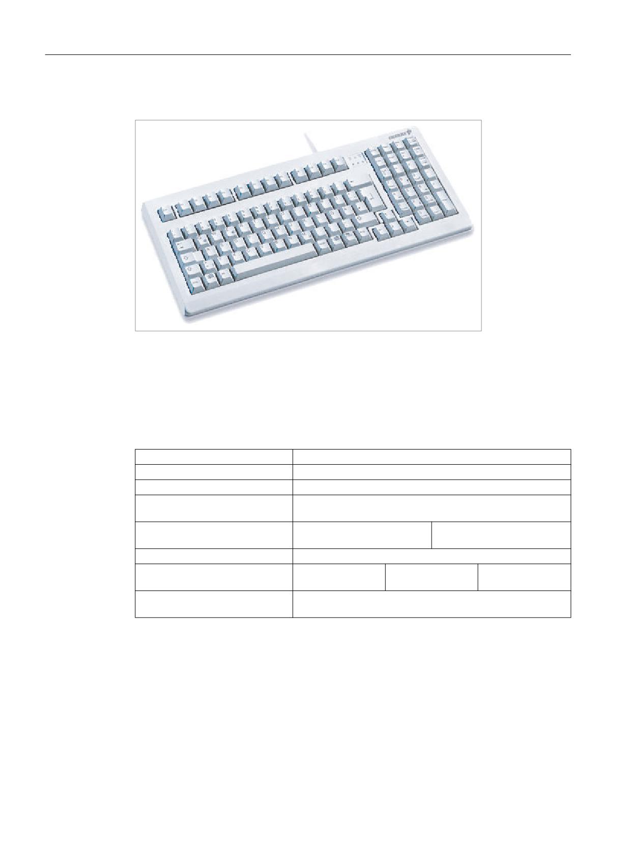
Standard PC keyboard KBPC CG US
1.3 Technical data
1.2
Operator controls and indicators
Image 1-1
View of PC standard keyboard: KBPC CG US
1.3
Technical data
Certificates and approvals
FCC, GS, CE, c-tick, cURus
Input voltage
+ 5.25 VDC
Power consumption
0.1 W
Degree of protection DIN EN 60529
IP20
(IEC 60529)
Permissible ambient temperature
Storage and transportation
Operation
- 20 ... 60° C
0 ... 50° C
Weight
Approx. 1.3 kg
Dimensions (mm)
Width:
Height:
Depth:
405
44
180
Electromagnetic compatibility
CE certification in accordance with EU Directives
EN 55022/B, EN 55024, EN 61000-3-2, EN 61000-3-3
Keyboards and additional components
6
Manual, 03/2016, 6FC5397-1AP40-5BA3
Keyboard tray
2
2.1
Description
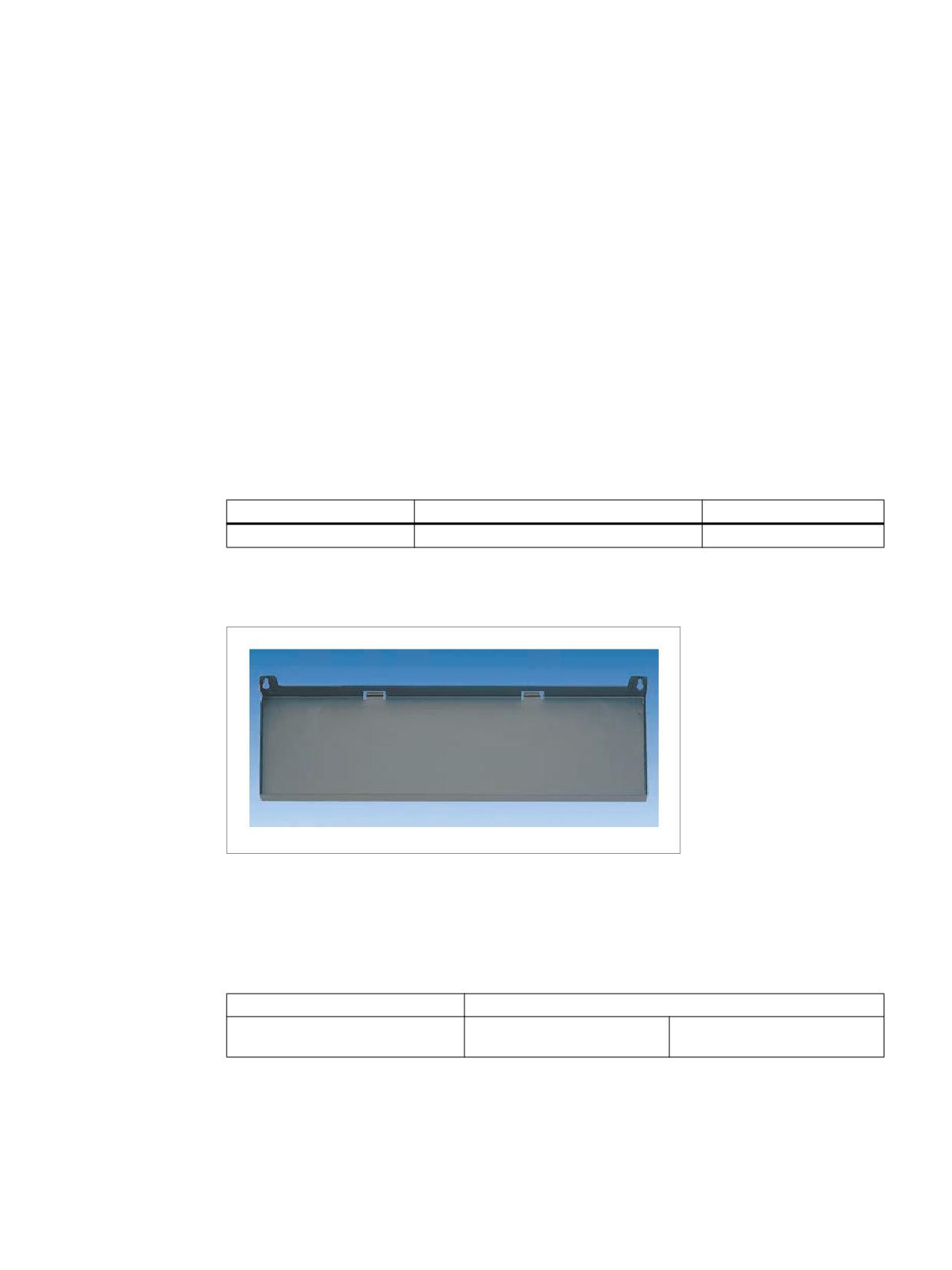
The extremely stable 19" keyboard tray in anthracite facilitates your work when using a
standard external keyboard with an operator panel.
Special screws permit easy attachment of the keyboard tray, and equally easy removal after
the work is finished.
If required, a version with an additional removable tray for a mouse is also available.
Validity
The description applies to the following components:
Designation
Remark
Article number
Keyboard tray
for keyboard with two collar screws
6FC5247-0AA40-0AA0
View
Image 2-1
View of keyboard tray
2.2
Technical data
Weight
approx. 1.6 kg
Dimensions (mm)
Width:
Depth:
487
196
Keyboards and additional components
Manual, 03/2016, 6FC5397-1AP40-5BA3
7
Keyboard tray
2.2 Technical data
Keyboards and additional components
8
Manual, 03/2016, 6FC5397-1AP40-5BA3
Full CNC keyboard: KB 310C
3
3.1
Description
The SINUMERIK KB 310C full CNC keyboard permits user-friendly input of programs and text.
It is fitted with short-stroke keys.
The key layout is predefined and cannot be modified, i.e. the key covers cannot be transposed.
The keyboard is mounted from the rear using special clamps included in the scope of delivery.
Validity
The following description applies to the component:
Designation
Keyboard
Article number
KB 310C full CNC keyboard
Mechanical
6FC5203-0AF21-0AA1
Features
● Keys
- Standard/US layout in QWERTY version
-
75 mechanical keys
● Key groups
- Alphabetic pad with special characters
- Numeric pad with special characters
- Cursor pad
- CNC function keys with hotkeys for fast selection of the operating area
● Connections
- USB 1.1 Full Speed
Keyboards and additional components
Manual, 03/2016, 6FC5397-1AP40-5BA3
9
Full CNC keyboard: KB 310C
3.2 Operating and display elements
3.2
Operating and display elements
Key assignments
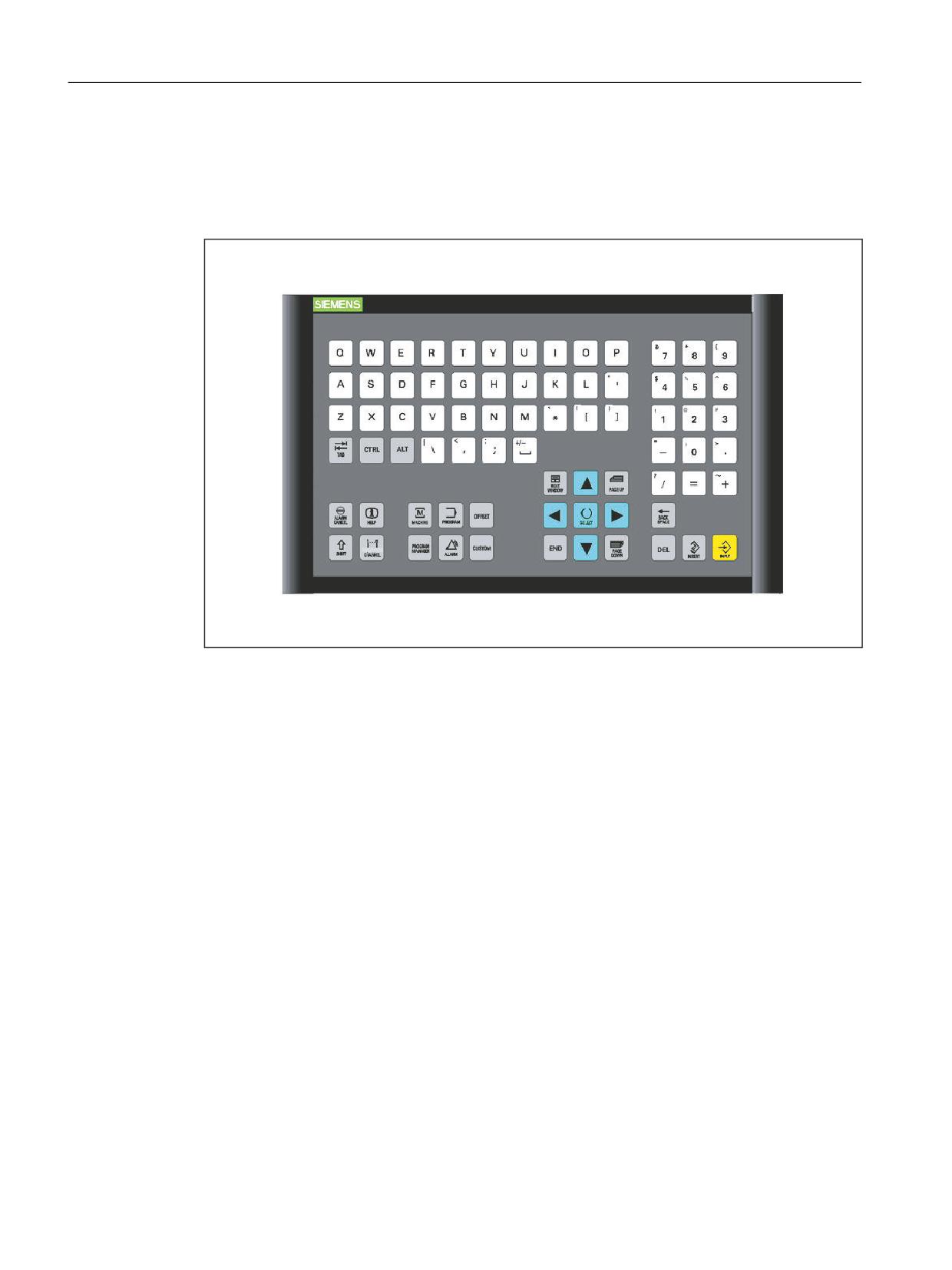
Image 3-1
Layout of CNC full keyboard KB 310C
Keyboard codes
For keyboard codes can be found in section: "CNC full keyboard KB 483C", section: "Operating
and display elements".
Keyboards and additional components
10
Manual, 03/2016, 6FC5397-1AP40-5BA3
Full CNC keyboard: KB 310C
3.3 Interfaces
3.3
Interfaces
'LPHQVLRQV LQ PP
3( WHUPLQDOV
;
86% %
&DEOH FODPS IRU 86% FDEOH
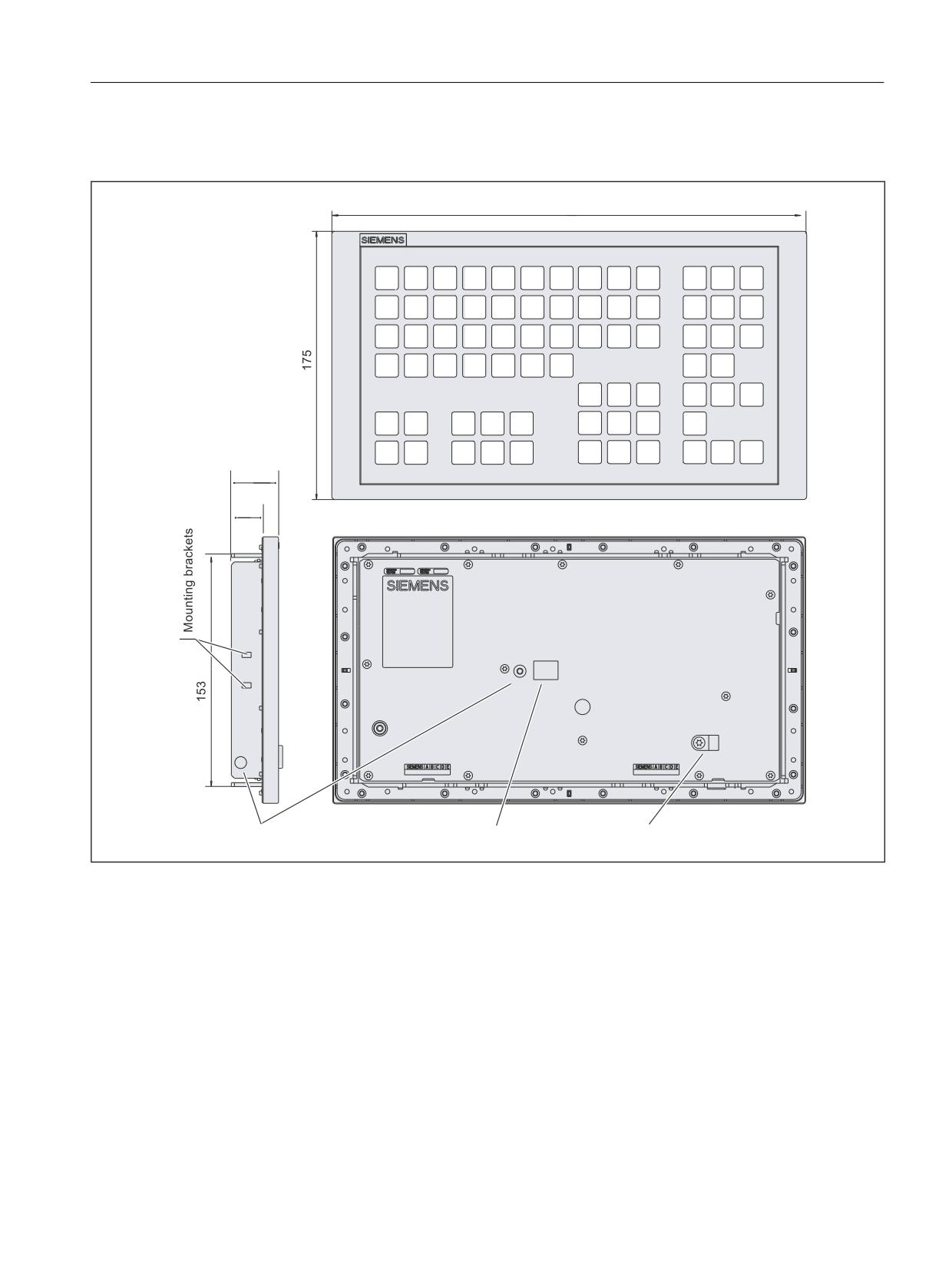
Image 3-2
Front, side and rear views of CNC full keyboard KB 310C
USB upstream port X302
The interface (see figure) is designed as a "high powered interface" (5 V / 500 mA). As a result,
the keyboard can be connected only to USB hubs which possess their own power supply and
whose downstream ports are capable of supplying a 500 mA current. A standard USB 2.0 Hi-
Speed cable of max. 3 m in length (recommended: 1.5 m) is supported.
Connector designation:
X302
Plug-connector type:
USB-B connector (4-pin)
Keyboards and additional components
Manual, 03/2016, 6FC5397-1AP40-5BA3
11
Full CNC keyboard: KB 310C
3.4 Mounting
Pin assignment see "General information and networking", Chapter: "Connecting"
3.4
Mounting
Note
When mounting, install and secure the USB connecting cable properly to ensure that it cannot
chafe against the frame of the keyboard.
Panel cutout
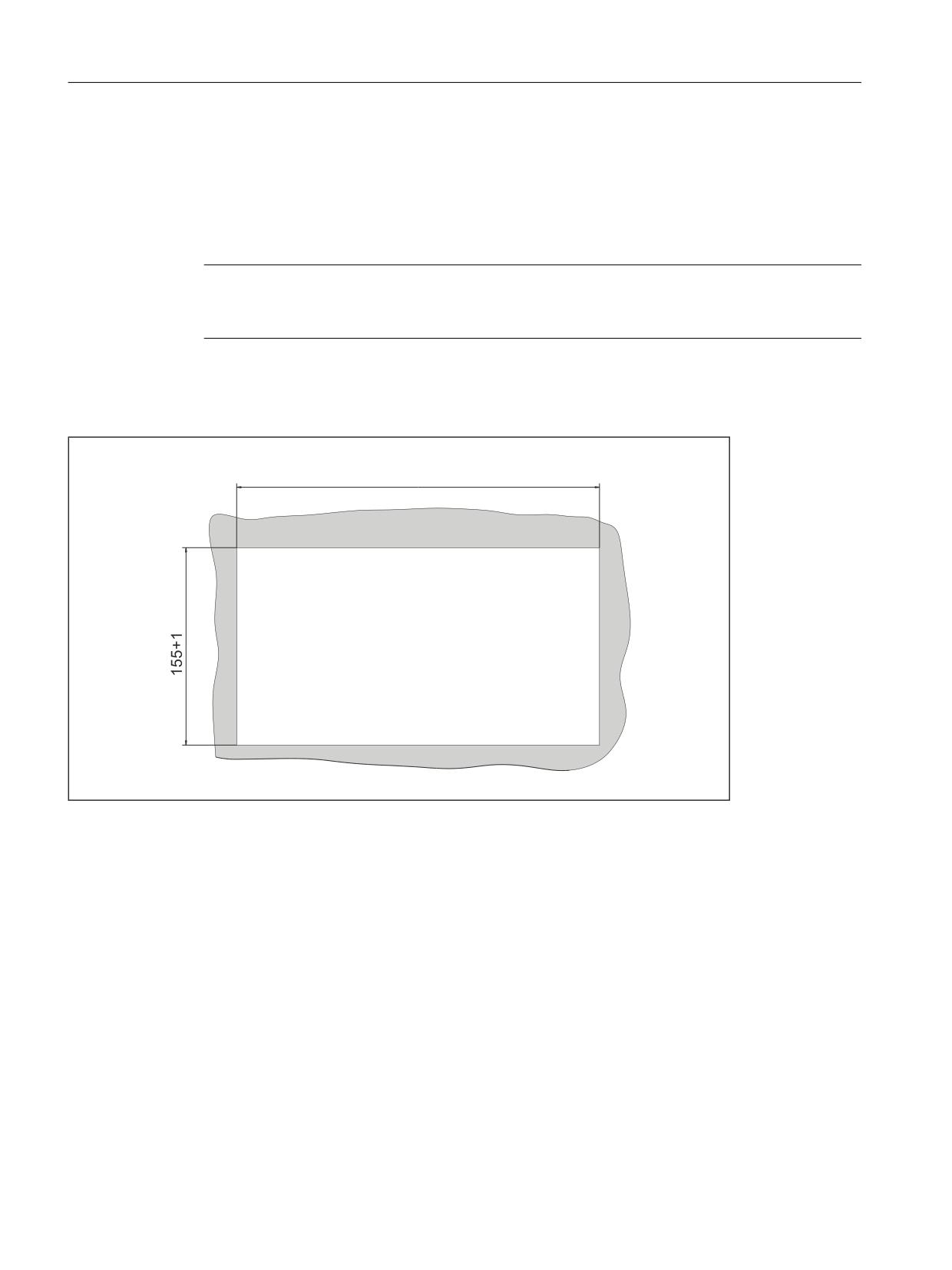
Image 3-3
Panel cutout for CNC full keyboard KB 310C (plate thickness 1.5 - 6.0 mm)
Keyboards and additional components
12
Manual, 03/2016, 6FC5397-1AP40-5BA3
Full CNC keyboard: KB 310C
3.4 Mounting
Dimension drawing for mounting
$
$
$ $
,Q WKH VHDOLQJ DUHD
PP
PP
0RXQWLQJ IUDPH
7HQVLRQ MDFNV
[
0RXQWLQJ IUDPH
'HWDLOHG YLHZ 0RXQWLQJ RI WHQVLRQ MDFNV
5HDU YLHZ ZLWK WHQVLRQ MDFNV
7RUTXH
1P
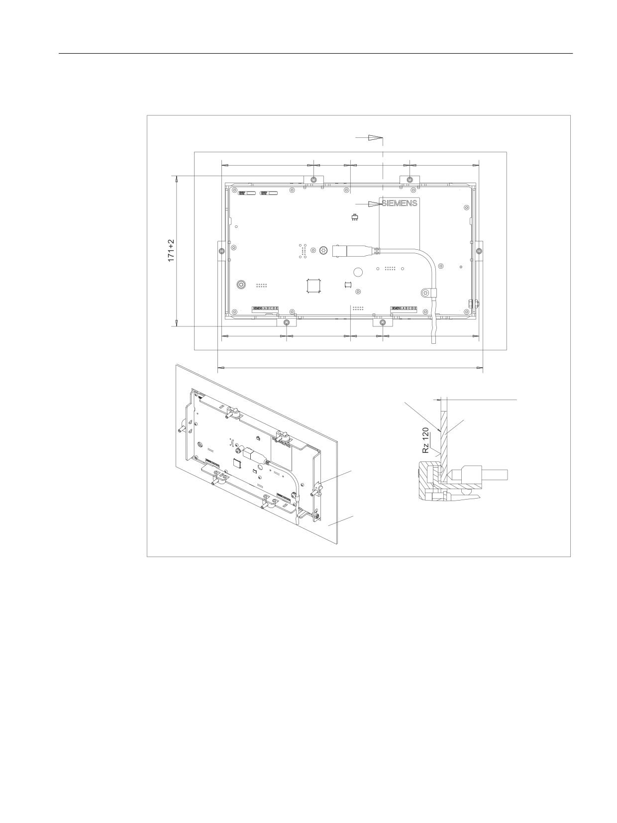
Image 3-4
Dimension drawing for mounting the CNC full keyboard KB 310C
Keyboards and additional components
Manual, 03/2016, 6FC5397-1AP40-5BA3
13
Full CNC keyboard: KB 310C
3.5 Technical data
Mounting position
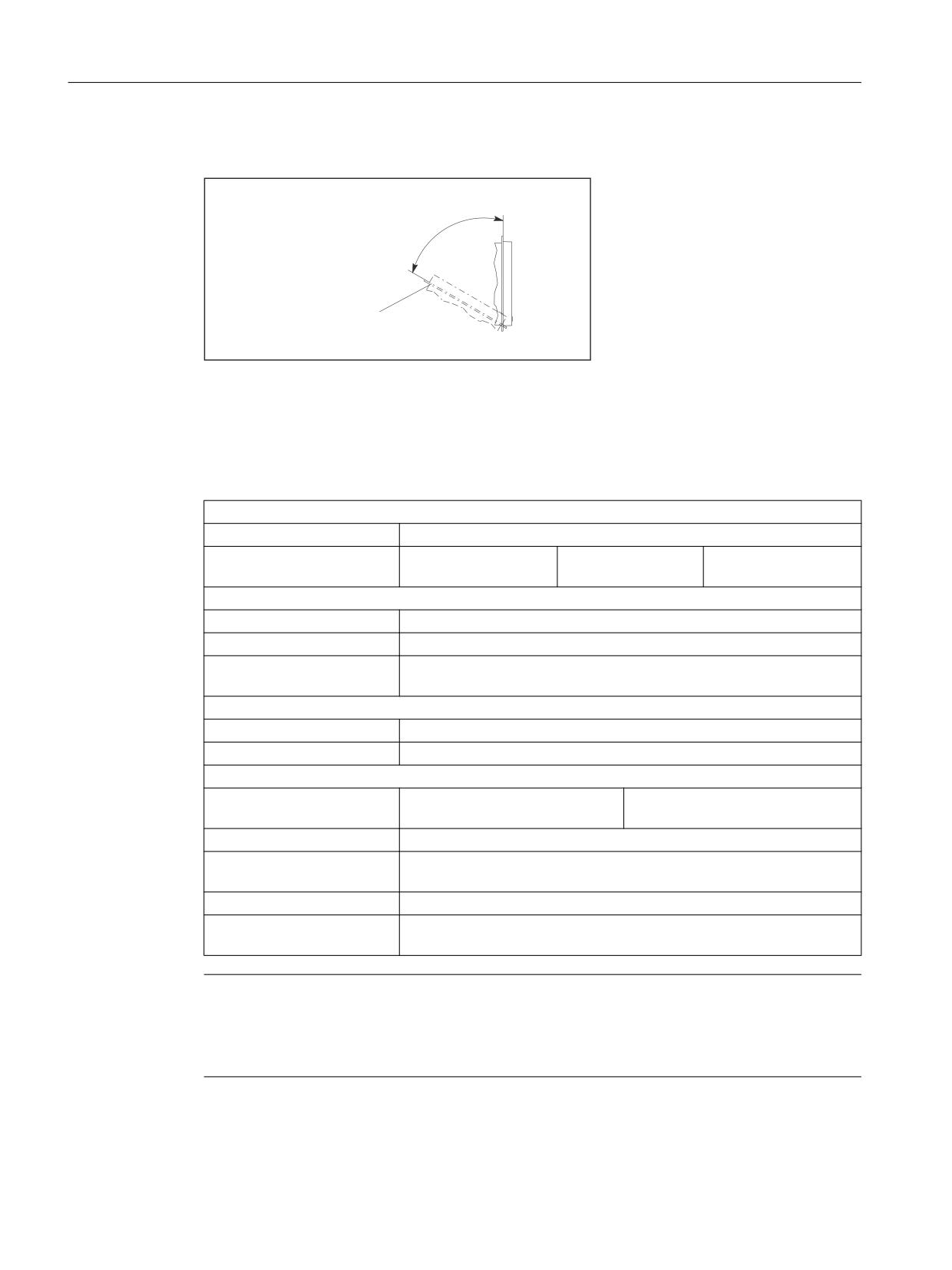
0RXQWLQJ SRVLWLRQ PD[
r
WR WKH YHUWLFDO
SHUPLWWHG
)URQW
Image 3-5
Mounting position
3.5
Technical data
Safety
Safety class / approvals
III; PELV according to EN 50178 / CE
Degree of protection accord-
Front side IP54
Rear side IP00
Seating to the
ing to EN 60529
cabinet: IP65
Immunity
ESD
Air discharge ± 8 kV / contact discharge ± 4 kV
HF radio
10 V/m, 80% AM, 1 kHz / 80 -1000 MHz
HF conducted (on USB ca-
10 V, 80% AM, 1 kHz / 0.15 - 80 MHz
ble)
Electrical data
Supply voltage / current (typ.)
4,75, ... 5.25 V / 102 mA
Power consumption, max.
0.4 W
Mechanical data
Dimensions
Width: 310 mm
Depth: 31 mm
Height: 175 mm
Mounting depth: 20 mm
Weight
Approx. 0.9 kg
Maximum distance to PCU/
3 m (recommended: 1.5 m)
TCU
Housing base color
Anthracite 614
Key color
Pastel turquoise RAL 6034, pantone yellow
light basic 700, medium basic 701
Note
Information about the climatic and mechanical environmental conditions is contained in the
associated section under:
"General notes and interconnection" → "Operational planning".
Keyboards and additional components
14
Manual, 03/2016, 6FC5397-1AP40-5BA3
Full CNC keyboard: KB 310C
3.6 Accessories
3.6
Accessories
Set of tension jacks
Component
Description
Quanti-
Article number
ty
Set of tension jacks
For supplementary operator com-
Set of 9
6FC5248-0AF14-0AA0
ponents with 2.5 mm profile, length:
20 mm
Keyboards and additional components
Manual, 03/2016, 6FC5397-1AP40-5BA3
15
Full CNC keyboard: KB 310C
3.6 Accessories
Keyboards and additional components
16
Manual, 03/2016, 6FC5397-1AP40-5BA3
Full CNC keyboard: KB 483C
4
4.1
Description
The SINUMERIK KB 483C full CNC keyboard permits user-friendly input of programs and text.
It is fitted with short-stroke keys.
The key layout is predefined and cannot be modified, i.e. the key covers cannot be transposed.
The keyboard is secured from the rear using special clamps supplied with the panel.
Validity
The following description applies to the component:
Designation
Key type
Article number
CNC full keyboard KB 483C
mechanical
6FC5203-0AF20-0AA1
Features
The keyboard has 78 mechanical keys based on the standard/US QWERTY layout.
● Key groups
- Alphabetic pad with special characters
- Numeric pad with special characters
- Cursor pad
- CNC function keys with hot keys for fast selection of the control area
● Connections
- USB 1.1 Full Speed
Keyboards and additional components
Manual, 03/2016, 6FC5397-1AP40-5BA3
17
Full CNC keyboard: KB 483C
4.2 Operating and display elements
4.2
Operating and display elements
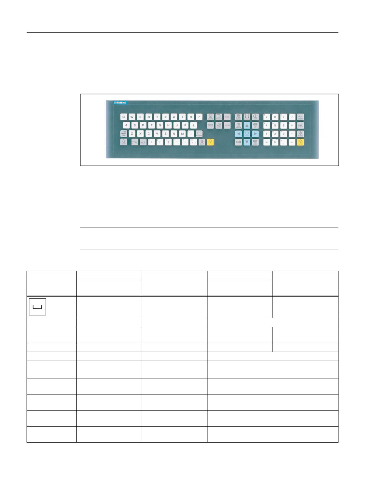
Key assignments
Image 4-1
Layout of CNC full keyboard KB 483C
The following table shows the differences of the key assignment to the US/standard keyboard.
Also note that the following keys on the KB 483C always correspond to the left-hand keys on
the standard keyboard:
Shift, Ctrl, Alt
Note
The keyboard does not support Suspend mode or a Remote Wakeup function.
KB 483C key
KB 483C key function
Corresponding US
KB 483C key function
Corresponding US
standard key
standard key
without SHIFT
with SHIFT
Space
Space
+/-
SHIFT + GRAVE AC-
CENT
=
=
=
Not connected
+
+
+ (NB)
~
SHIFT + GRAVE AC-
CENT
*
*
SHIFT + 8
'
'
INPUT
Input confirmation
ENTER
Not connected
MACHINE
Calls the "Machine" op-
SHIFT + F11
Not connected
erating area.
PROGRAM MAN-
Calls the "Program Man-
7 (NB)
Not connected
AGER
ager" operating area.
PROGRAM
Calls the "Program" op-
1 (NB)
Not connected
erating area.
ALARM
Calls the "Diagnosis" op-
9 (NB)
Not connected
erating area.
OFFSET
Calls the "Parameters"
3 (NB)
Not connected
operating area.
Keyboards and additional components
18
Manual, 03/2016, 6FC5397-1AP40-5BA3

Full CNC keyboard: KB 483C
4.2 Operating and display elements
KB 483C key
KB 483C key function
Corresponding US
KB 483C key function
Corresponding US
standard key
standard key
without SHIFT
with SHIFT
CUSTOM
Calls the "Custom" oper-
SHFT + F12
Not connected
ating area.
ALARM CANCEL
Deletes alarms and
ESC
SW-dependent
SHIFT + ESC
messages.
CHANNEL
Steps for multiple chan-
F11
Not connected
nels.
HELP
Calls the context-sensi-
F12
Not connected
tive online help.
NEXT WINDOW
Toggles between the
HOME
Selects the first entry in
SHIFT + HOME
windows.
the selection lists.
SELECT
Steps in selection lists.
5 (NB)
SW-dependent
SHIFT + 5 (NB)
NB = numeric block
The key functions of the SINUMERIK keyboard depend on the used operating software and
largely match the keys of the operator panels. A detailed description of the keys is contained
in the operating manuals.
Keyboards and additional components
Manual, 03/2016, 6FC5397-1AP40-5BA3
19
Full CNC keyboard: KB 483C
4.3 Interfaces
4.3
Interfaces
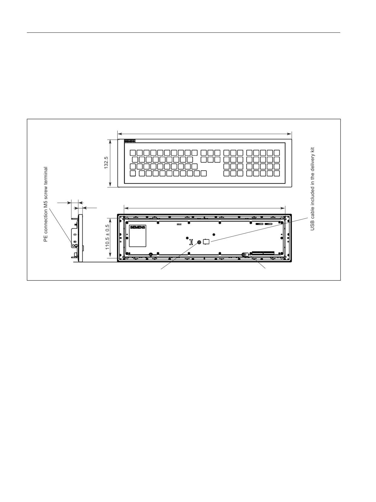
s
;
'LPHQVLRQV LQ PP
3( FRQQHFWLRQ VFUHZ WHUPLQDO
&DEOH FODPS
Image 4-2
Front, side and rear views of CNC full keyboard KB 483C
USB upstream port X302
The interface (see figure) is designed as a "high powered interface" (5 V / 500 mA). As a result,
the keyboard can be connected only to USB hubs which possess their own power supply and
whose downstream ports are capable of supplying a 500 mA current. A standard USB 2.0 Hi-
Speed cable of max. 3 m in length (recommended: 1.5 m) is supported.
Connector designation:
X302
Connector type:
USB-B connector (4-pin)
Pin assignment see "General information and networking", Chapter: "Connecting"
Keyboards and additional components
20
Manual, 03/2016, 6FC5397-1AP40-5BA3
Full CNC keyboard: KB 483C
4.4 Mounting
4.4
Mounting
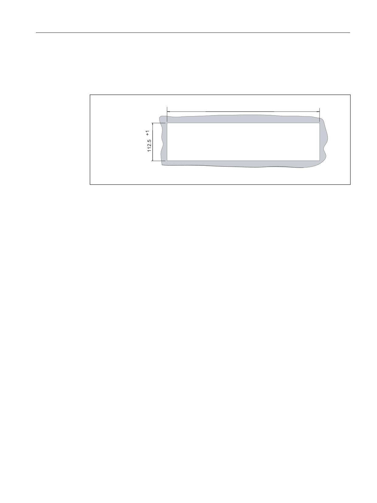
Panel cutout
'LPHQVLRQV LQ PP
Image 4-3
Panel cutout for CNC full keyboard KB 483C (plate thickness 1.5 - 6.0 mm)
Keyboards and additional components
Manual, 03/2016, 6FC5397-1AP40-5BA3
21
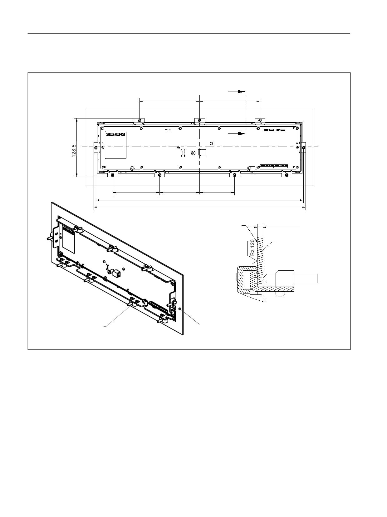
Full CNC keyboard: KB 483C
4.4 Mounting
Dimension drawing
$
$
,Q WKH V
HDOLQJ DUHD
PP
PP
0RXQWLQJ IUDPH
$$
5HDU YLHZ
ZLWK WHQVLRQ MDFNV
'HWDLO
0RXQWLQJ RI WHQVLRQ MDFNV
7RUTXH
b1P
7HQVLRQ
MDFNV
0RXQWLQJ IUDPH
'LPHQVLRQV LQ PP
[
Image 4-4
Dimension drawing for mounting the CNC full keyboard KB 483C
Keyboards and additional components
22
Manual, 03/2016, 6FC5397-1AP40-5BA3
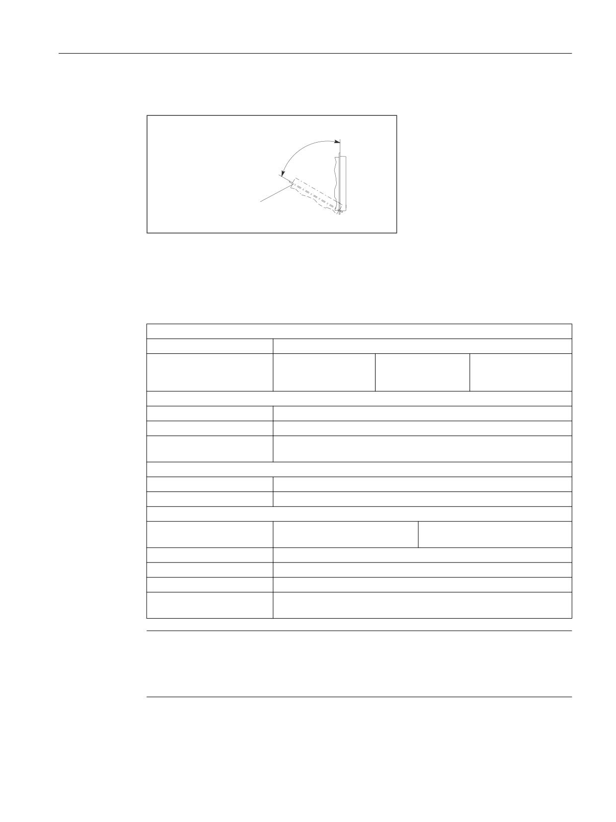
Full CNC keyboard: KB 483C
4.5 Technical data
Mounting position
0RXQWLQJ SRVLWLRQ PD[
r
WR WKH YHUWLFDO
SHUPLWWHG
)URQW
Image 4-5
Mounting position
4.5
Technical data
Safety
Safety class / approvals
III; PELV according to EN 50178 / CE
Degree of protection accord-
Front side IP54
Rear side IP00
Fusing to
ing to EN 60529
cabinet: IP65
(IEC 60529)
Immunity
ESD
Air discharge ± 8 kV / contact discharge ± 4 kV
HF radio
10 V/m, 80% AM, 1 kHz / 80 -1000 MHz
HF conducted (on USB ca-
10 V, 80% AM, 1 kHz / 0.15 - 80 MHz
ble)
Electrical data
Supply voltage / current (typ.)
4,75, ... 5.25 V / 102 mA
Power consumption, max.
0.4 W
Mechanical data
Dimensions
Width: 483 mm
Depth: 31 mm
Height: 133 mm
Mounting depth: 20.2 mm
Weight
approx. 1.3 kg
Max. distance from PCU
3 m (recommended: 1.5 m)
Housing base color
Anthracite 614
Key color
Pastel turquoise RAL 6034, pantone yellow
light basic 700, medium basic 701
Note
Information about the climatic and mechanical environmental conditions is contained in the
associated section under:
"General notes and interconnection" → "Operational planning".
Keyboards and additional components
Manual, 03/2016, 6FC5397-1AP40-5BA3
23
Full CNC keyboard: KB 483C
4.6 Accessories
4.6
Accessories
Set of tension jacks
Component
Description
Quanti-
Article number
ty
Set of tension jacks
For supplementary operator com-
Set of 9
6FC5248-0AF14-0AA0
ponents with 2.5 mm profile, length:
20 mm
Keyboards and additional components
24
Manual, 03/2016, 6FC5397-1AP40-5BA3
CompactFlash card
5
5.1
Description
The CompactFlash card stores the user data.
Validity
The following description applies to the following components
Designation
Article number
SINUMERIK CompactFlash card, 1 GB, empty
6FC5313-5AG00-0AA1
SINUMERIK CompactFlash card, 2 GB, empty
6FC5313-5AG00-0AA2
SINUMERIK CompactFlash card, 8 GB, empty
6FC5313-6AG00-0AA0
Safety instructions
● Insert the CompactFlash card carefully with the correct orientation into the memory card
slot (observe indicators such as arrow or similar). This way you avoid mechanical damage
to the memory card or the device. Note the general ESD information.
● Only use the memory card type provided by Siemens with its formatting (e.g. FAT16) for
your device, in order to guarantee the basic functions - especially when the operating
system is started from the card.
● It is recommended that the card contents be backed up regularly. Use the appropriate
procedure in the respective documentation.
● Do not remove the memory card while it is being accessed. If possible, use the eject function
for removable data carriers in Windows. If this is not observed, it can result in data loss
through to irreparable damage of the memory card.
● If a memory card does not function with your device, it may be an unsuitable card, a card
not formatted for the device or a card with defective contents.
● Protect an unused card against pollution - especially the connector area - by keeping it in
a suitable protective sleeve.
Keyboards and additional components
Manual, 03/2016, 6FC5397-1AP40-5BA3
25
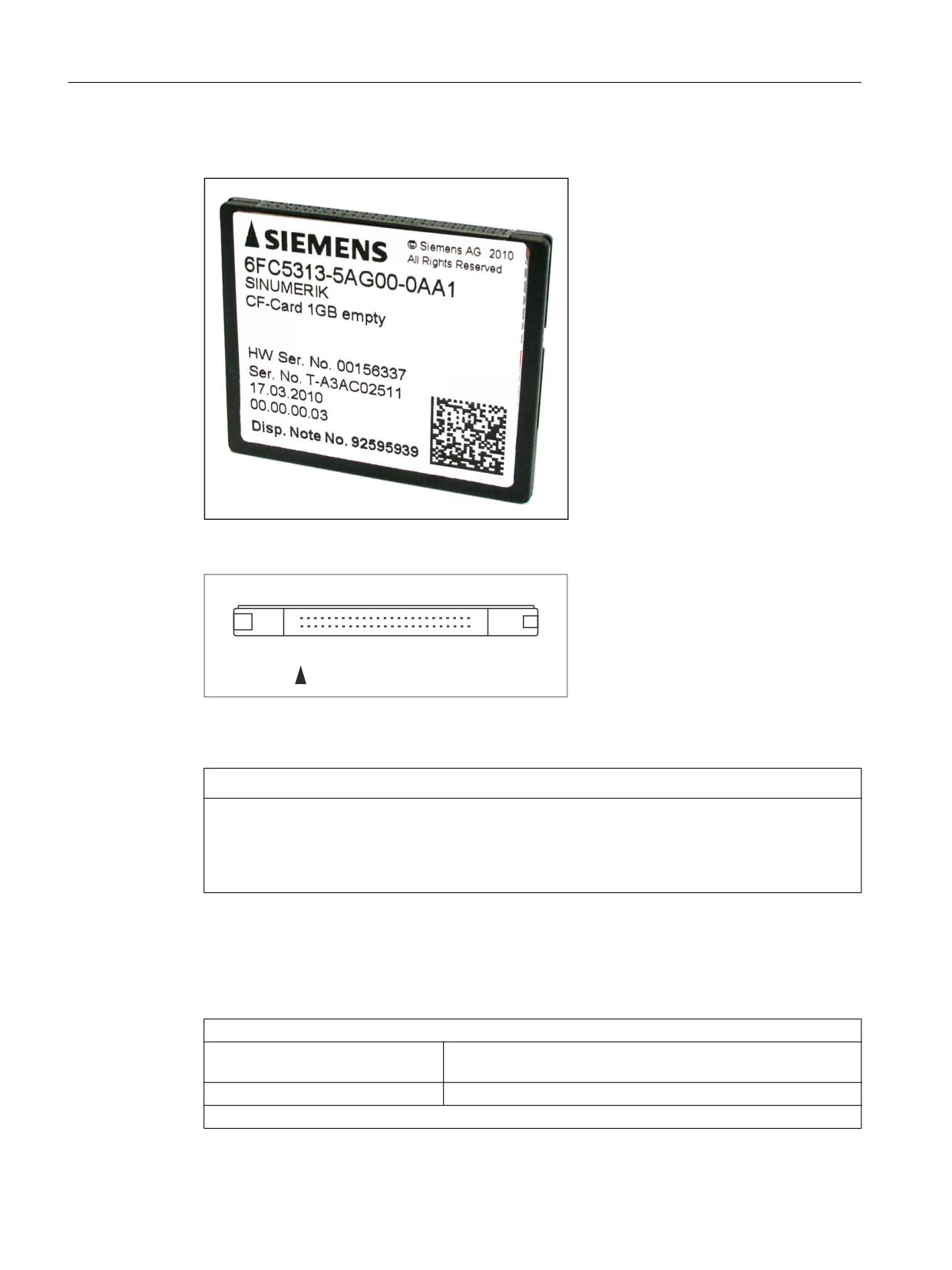
CompactFlash card
5.2 Technical data
View
Image 5-1
View of the CompactFlash card
Image 5-2
Schematic diagram of the CompactFlash card socket connector
NOTICE
Note reverse polarity protection
Do not use force to insert the CompactFlash card. There are various guide grooves to protect
against reverse polarity. As can be seen in the above figure, the groove on the left is wider
than the groove on the right. The arrow always indicates pin 1.
5.2
Technical data
Safety
Degree of protection according to
IP20
EN 60529
Approvals
CE / cULus
Electrical data
Keyboards and additional components
26
Manual, 03/2016, 6FC5397-1AP40-5BA3

CompactFlash card
5.2 Technical data
Supply voltage
5.5 V DC
Mechanical data
Dimensions (mm)
Width:
Height:
Depth:
43
3
37
Weight
12 g
Climatic environmental conditions
Condensation, spray water and icing
Not permitted
Operation
Storage and transportation
Applicable standards
EN 60721-3-3
EN 60721-3-1 / -3-2
Permissible ambient temperature
0 ... 85 °C
-40 ... 100 °C
Limits for relative humidity
10 ... 80 %
5 ... 95 %
Keyboards and additional components
Manual, 03/2016, 6FC5397-1AP40-5BA3
27
Card reader with USB interface
6
6.1
Description
The SINUMERIK card reader is intended for archiving and exchanging user data.
The card reader is connected via the USB interface.
It can be installed in a front panel. This makes data exchange possible without opening the
control cabinet.
The card reader can be booted.
All cards can be inserted and removed during operation.
Validity
This description applies to the card reader
Article number: 6FC5335-0AA00-0AA0.
Features
● Suitable for CF, SD, and MMC cards
● Installation in front panels
● Bootability
● Connection: USB 2.0 Hi-Speed
The card reader is delivered with attached 1 m USB cable.
Possible connections
The card reader is suitable for connection to:
● PCU 50.5
● TCU x0.2
Keyboards and additional components
Manual, 03/2016, 6FC5397-1AP40-5BA3
29
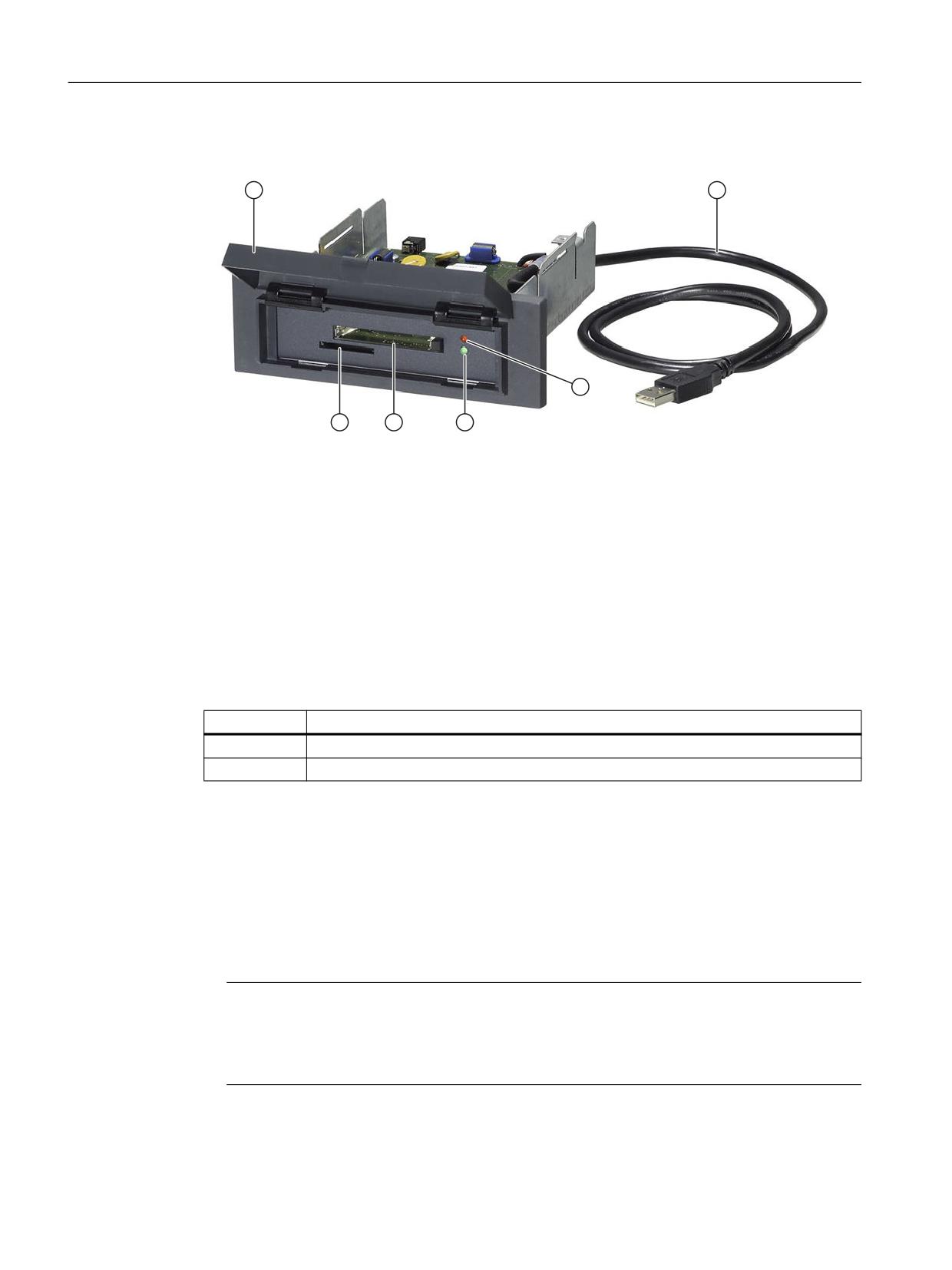
Card reader with USB interface
6.2 Operator controls and indicators
6.2
Operator controls and indicators
① Slot cover
② USB line
③ LED for displaying read and write processes (red)
④ LED for displaying operational readiness (green)
⑤ Slot for CF cards
⑥ Slot for SD / MMC cards
Image 6-1
Front view of the USB card reader
Function of the LEDs
Two LEDs (see Fig.) with different functions are located next to the slot for CF cards.
LED
Display
Green
lit permanently if the card reader is ready for operation
Red
lit if reading or writing is in progress
Card slots
The two card slots of the reader are located under the cover.
Cards can be inserted in both slots at the same time as they operate simultaneously. In this
way, it is possible to
● Copy files from one card to the other,
● Read or write to the media from various applications at the same time.
Note
Only use card types and sizes offered by Siemens.
The corresponding article numbers can be found in Catalog NC 61.
We cannot guarantee that every card available on the market can be used.
Keyboards and additional components
30
Manual, 03/2016, 6FC5397-1AP40-5BA3
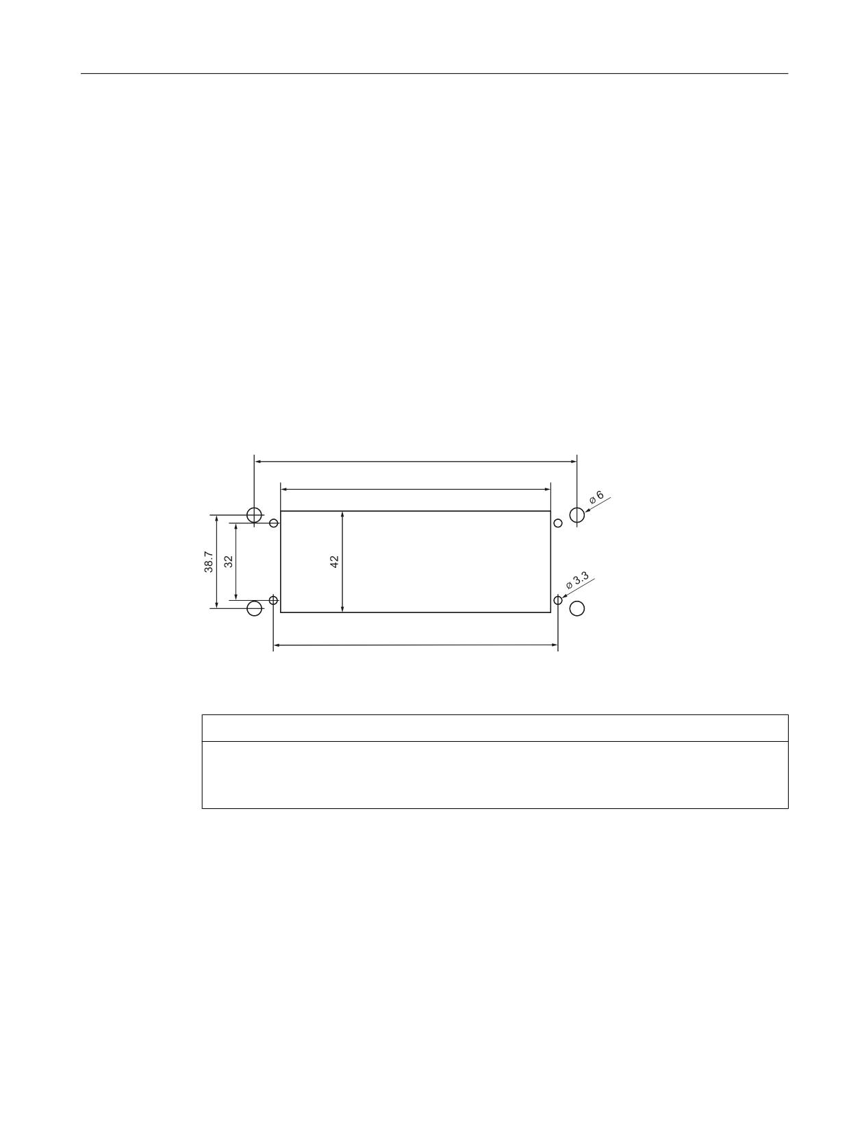
Card reader with USB interface
6.5 Memory cards
6.3
interfaces
The card reader has a USB interface (USB 2.0 Hi-Speed).
The card reader can be connected via this interface to a USB interface of the PCU/TCU whose
maximum current carrying capacity is 500 mA.
Transmission rate
If the card reader is connected to a USB 2.0 interface, the bus speed is automatically 480
Mbps (Hi-Speed).
On a USB 1.1 interface, the card reader switches to 12 Mbps (Full Speed).
6.4
Installation
0 IL[LQJ VFUHZ
PD[ VFUHZ LQ GHSWK PP
Image 6-2
Panel cutout
NOTICE
Damage to the drive drive for open top cover
The slot cover of the card reader must be closed to prevent dirt entering or damage during
installation.
6.5
Memory cards
The card reader is suitable for
● Compactflash cards (CF)
● SecureDigital cards (SD)
● Multimedia cards (MMC)
● MicroMemory cards (Simatic MMC)
Keyboards and additional components
Manual, 03/2016, 6FC5397-1AP40-5BA3
31
Card reader with USB interface
6.6 Technical data
Note
The read and write speed depends on the card used!
Booting
With the exception of the Simatic MMC, all other cards are bootable.
Card type
Bootable
CF cards
X
SD cards
X
MMC cards
X
Simatic MMC cards
-
Note
The card reader works like a USB drive.
Please note therefore that restrictions in the BIOS or operating system may not always allow
booting from such a drive.
6.6
Technical data
Safety
Safety class
III; PELV according to EN 50178
Degree of protection according to
Front IP54
Rear IP00
EN 60529
Approvals
CE / cULus
Electrical data
Input voltage
4.75 - 5.25 VDC
Input current
Max. 500 mA
Mechanical data
Dimensions
Width: 145 mm
Depth: 143 mm
Height: 50 mm
Mounting depth: 125 mm
Weight
Approx. 0.4 kg
Card slots
2 (for every 10,000 mating cycles)
Climatic environmental conditions
Condensation, spray water and icing
Not permitted
Operation
Storage and transportation
Perm. ambient temperature
0 ... 70° C
-20 ... 85° C
Limits for relative humidity
5 ... 90%
5 ... 95%
Keyboards and additional components
32
Manual, 03/2016, 6FC5397-1AP40-5BA3
Card reader with USB interface
6.7 Accessories
Note
Information about the climatic and mechanical environmental conditions is contained in the
associated section under:
"General notes and interconnection" → "Operational planning".
6.7
Accessories
The following accessories are available for the card reader:
Component
Description
Number
Article number
Cover
for diskette drive and card reader
1
6FC5247-0AA20-0AA0
Keyboards and additional components
Manual, 03/2016, 6FC5397-1AP40-5BA3
33
Card reader with USB interface
6.7 Accessories
Keyboards and additional components
34
Manual, 03/2016, 6FC5397-1AP40-5BA3
USB extension
7
Description
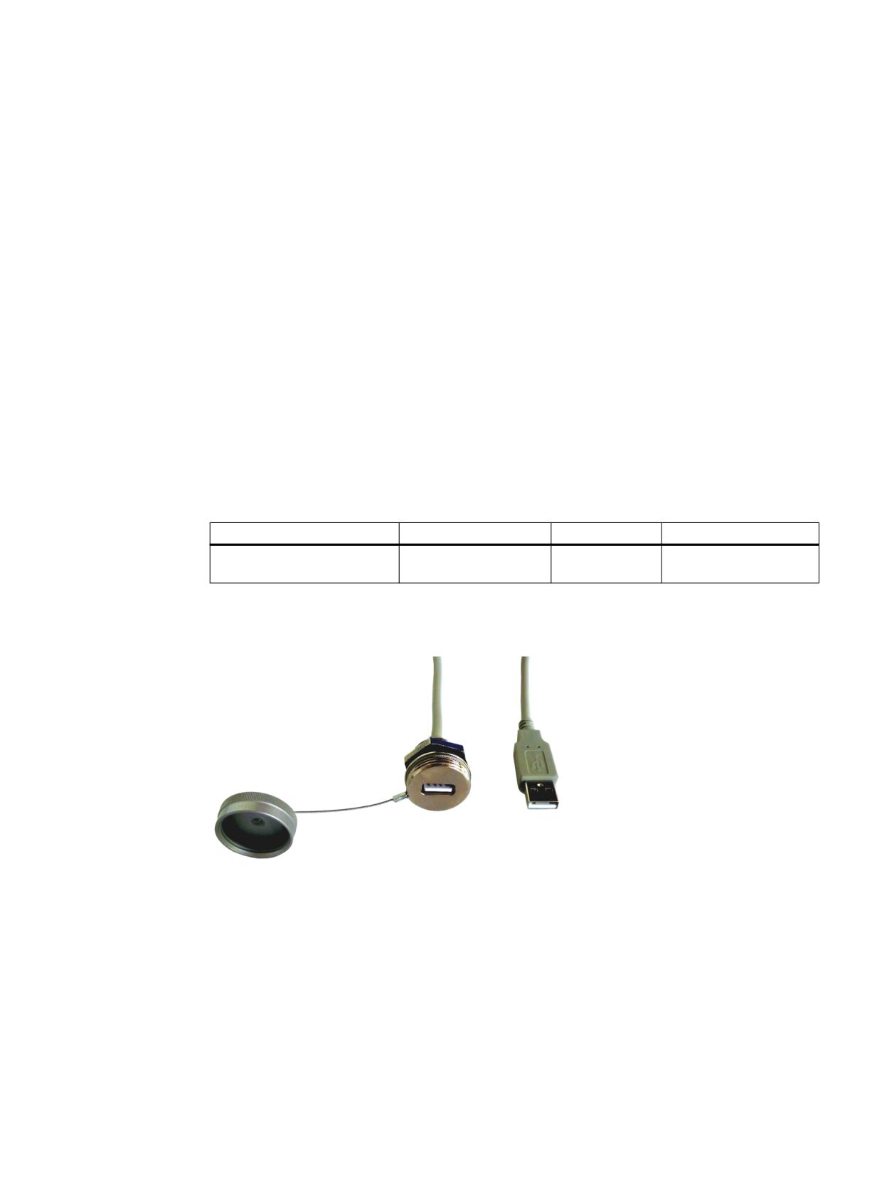
Some operator panel fronts have no USB front interfaces. If required, you can, however, use
the USB interfaces for PCU/TCU. The USB extension is used for external connection of the
rear USB interface to the operator panel housing front.
Advantages:
● Undetachable protective cover.
● The bolted protective cap retains the degree of protection of the housing.
● Because the locknut automatically cuts itself into the paint or anodized layer, a conductive
connection results.
Validity
This description applies to the following component:
USB standard
Length
Article number
USB extension
1.1 Full Speed, 2.0 Hi-
1 m
6FC5347-0AF01-1AA0
Speed
Display
Image 7-1
USB extension
Keyboards and additional components
Manual, 03/2016, 6FC5397-1AP40-5BA3
35
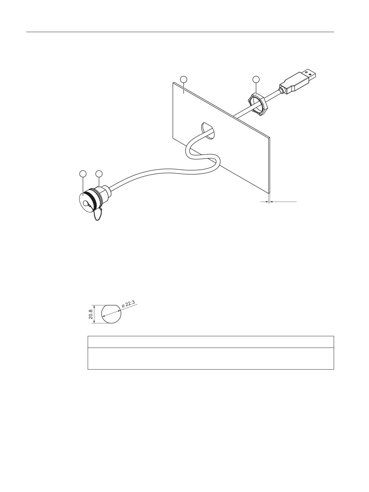
USB extension
Mounting
PP
① Protective cap
② Anti-twist protection
③ Operator panel housing front
④ Locknut
Image 7-2
Laying the USB extension
1. Mark the position on the operator panel housing front for the cable entry.
2. Punch the hole for the cable entry in order to ensure the anti-twist protection:
NOTICE
Damage to the USB extension
The USB cable must not be damaged. Consequently, remove any burrs in the hole.
3. Insert the USB extension through the hole.
4. Tighten the locknut with a tightening torque of 0.5 Nm to 0.75 Nm.
Keyboards and additional components
36
Manual, 03/2016, 6FC5397-1AP40-5BA3
Index
C
U
Card reader
USB technology
Dimensions, 32
KB 310C, 11
CF card
KB 483C, 20
Dimensions, 27
CNC keyboard
KB 310C, 9
KB 483C, 17
K
KB 310C
CNC keyboard, 9
Dimension drawing, 13
Dimensions, 14
Key codes, 10
Key groups, 9
Key layout, 9, 10
Mounting position, 14
Power consumption, 14
USB technology, 11
KB 483C
CNC keyboard, 17
Dimension drawing, 22
Dimensions, 23
Key groups, 17
Key layout, 17, 18
Mounting position, 23
Power consumption, 23
USB technology, 20
KBPC CG US standard PC keyboard
Dimensions, 6
Power consumption, 6
Key codes
KB 310C, 10
Key groups
KB 310C, 9
KB 483C, 17
Key layout
KB 310C, 9, 10
KB 483C, 17, 18
Keyboard tray
Dimensions, 7
Keyboards and additional components
Manual, 03/2016, 6FC5397-1AP40-5BA3
37

Appendix
A
A.1
Abbreviations
AC
Alternating Current
ASIC
Application-Specific Integrated Circuit
BA
Mode selector switch
BIOS
Basic Input Output System
HHU
Handheld Unit
ALS
Authorization Lock Switch
OPI
Operator Panel Interface
CCFL
Cold Cathode Fluorescent Lamp: fluorescent lamp for backg10round lighting
CDROM
Compact Disk ROM
CRT
Cathode Ray Tube
COM
Communications module
CPU
Central Processing Unit
DC
Direct Current
DCP
Discovery and basic Configuration Protocol: Standard for the assignment of IP addresses
DIP
Dual In-Line Package: dual in-line arrangement
DRAM
Dynamic RAM
DKM
Direct Key Module
I/O
Input/Output
ECC
Error Correction Code: method error correction in memory blocks
ESD
Electrostatic Sensitive Device
EKS
Electronic Key System: Identification system from EUCHNER
EMC
Electromagnetic Compatibility
EEA
European Economic Area
FB
Function Block
EN
European standard
PCB
Function Block Group
FSB
Front Side Bus
GD
Global Data communication
GND
Ground
GSD
Generic Station Description: The file describes a PROFIBUS slave in accordance with the PROFIBUS
standard
INC
Increment: Increment
HAM
Handwheel connection module
HF
Function keys LED
HGA
Connection for handheld units
HID
Human Interface Device: Device class of the USB standard that describes devices with which users interact
directly, e.g. keyboard, mouse.
Operator Components and Networking
Manual, 03/2016, 6FC5397-1AP40-5BA3
17

Appendix
A.1 Abbreviations
HMI
Human Machine Interface: SINUMERIK operator interface for operating, programming and simulation.
HT
Handheld Terminal
HW
Hardware
IC
Integrated Circuit: integrated electronic circuit
IDE
Integrated Drive Electronics
IE
Industrial Ethernet
I/O
Input/Output
IP
International Protection: ID letter for IPxx degree of protection
ISA
Industry Standard Architecture: Bus standard for IBM-compatible PCs
KT
Customer keys
LCD
Liquid Crystal Display
LE
Long Element
LED
Light-Emitting Diode
LPT
Line Print Terminal: Data transfer via a parallel interface
LVDS
Low Voltage Differential Signaling: standardized high-speed data transmission for the digital control of liquid
crystal screens.
MCP
Machine Control Panel
MFII
Multifunction keyboard II
Modem
Modulator-demodulator
MPI
Multi-Point Interface: multi-point serial interface
MPP
Machine Pushbutton Panel
MCP
Machine Control Panel (MCP/MPP)
N.C.
Not Connected: Connection unassigned
NAU
Power failure
NC
Numerical Control
NCK
Numerical Control Kernel
NCU
Numerical Control Unit
ODU
Plug connector system
OP
Operator Panel: Operator panel front
PC
Personal Computer
PCU
PC Unit: computer unit
PE
Potential Earth
PELV
Protective Extra-Low Voltage
PG
Programming device
PLC
Programmable Logic Controller: component of the numerical control system
PNO
PROFIBUS user organization
PROFIBUS
Process Field Bus
RAM
Random Access Memory: Read/write memory
ROM
Read Only Memory
S/R
Steps per Revolution
SDRAM
Synchronous Dynamic Random Access Memory: synchronous DRAM
SR
Mushroom button - rapid withdrawal
SSD
Solid State Drive: Electronic hard disk drive
STN
Super Twisted Nematic: Flat screen technology
Operator Components and Networking
18
Manual, 03/2016, 6FC5397-1AP40-5BA3

Appendix
A.1 Abbreviations
SVGA
Super VGA: Screen resolution 800 x 600 pixels, maximum 16.7 million colors
SXGA
Super Extended Graphics Array: Screen resolution 1280 x 1024 pixels
SW
Software
TCU
Thin Client Unit
TFT
Thin Film Transistor (flat screen technology)
UL
Underwriters Laboratories
USB
Universal Serial Bus
V.24
Interface standard in accordance with CCITT V.24
VGA
Video Graphics Array: Computer graphics standard with 640 x 480 pixel resolution, 16 colors
WS
Selector switch
XGA
Extended Graphics Array: Screen resolution 1024 x 768 pixels
Operator Components and Networking
Manual, 03/2016, 6FC5397-1AP40-5BA3
19

Preface
Fundamental safety
1
instructions
2
System overview
SINUMERIK
3
Description
SINUMERIK 840D sl type 1B
4
Application planning
NCU 7x0.3 PN, NCU 7x0.3B PN
5
Dimension drawings
Manual
6
Assembling
7
Connecting
8
Technical data
9
Connectable components
10
Spare Parts/Accessories
A
Appendix
Valid for
SINUMERIK 840D sl / 840DE sl control
06/2014
6FC5397-1EP40-5BA1
Preface
SINUMERIK documentation
The SINUMERIK documentation is organized in the following categories:
● General documentation
● User documentation
● Manufacturer/service documentation
Additional information
You can find information on the following topics at http://www.siemens.com/motioncontrol/
docu:
● Ordering documentation/overview of documentation
● Additional links to download documents
● Using documentation online (find and search in manuals/information)
Please send any questions about the technical documentation (e.g. suggestions for
improvement, corrections) to the following address:
mailto:docu.motioncontrol@siemens.com
My Documentation Manager (MDM)
Under the following link you will find information to individually compile OEM-specific machine
documentation based on the Siemens content:
Training
For information about the range of training courses, refer to:
SITRAIN - Siemens training for products, systems and solutions in automation technology
SinuTrain - training software for SINUMERIK
FAQs
You can find Frequently Asked Questions in the Service&Support pages under Product
Support.
NCU 7x0.3 PN, NCU 7x0.3B PN
Manual, 06/2014, 6FC5397-1EP40-5BA1
3
Preface
SINUMERIK
You can find information on SINUMERIK under the following link:
Target group
This documentation is intended for manufacturers of machine tools, particularly:
● Project engineers, electricians and installers
● Maintenance and service personnel
Benefits
The information in this manual facilitates installation and connection of the SINUMERIK 840D
numerical control in the control cabinet.
Standard scope
This documentation only describes the functionality of the standard version. Extensions or
changes made by the machine tool manufacturer are documented by the machine tool
manufacturer.
Other functions not described in this documentation might be executable in the controller. This
does not, however, represent an obligation to supply such functions with a new controller or
when servicing.
Further, for the sake of simplicity, this documentation does not contain all detailed information
about all types of the product and cannot cover every conceivable case of installation, operation
or maintenance.
Technical Support
You will find telephone numbers for other countries for technical support in the Internet under
EC Declaration of Conformity
The EC Declaration of Conformity for the EMC Directive can be found on the Internet at:
NCU 7x0.3 PN, NCU 7x0.3B PN
4
Manual, 06/2014, 6FC5397-1EP40-5BA1
Table of contents
Preface
3
1
Fundamental safety instructions
9
1.1
General safety instructions
9
1.2
Handling electrostatic sensitive devices (ESD)
12
1.3
Industrial security
12
1.4
Residual risks of power drive systems
13
2
System overview
17
2.1
Application
17
2.2
System configuration
17
2.3
Variants
20
2.4
Ordering data
21
3
Description
23
3.1
Characteristics
23
3.2
Illustration
23
3.3
Type plates
25
3.4
Operator control and display elements
26
3.4.1
Overview of operating and display elements
26
3.4.2
LED displays
26
3.4.3
7-segment display
27
3.4.4
RESET button
28
3.4.5
Start-up and mode selector switch
29
3.5
Dual fan/battery module
29
4
Application planning
31
4.1
Secondary electrical conditions
31
4.1.1
Grounding concept
31
4.1.2
RI suppression measures
31
4.2
Climatic and mechanical environmental conditions
33
4.2.1
Shipping and storage conditions
33
4.2.2
Operating conditions
35
4.3
Recycling and disposal
36
5
Dimension drawings
37
6
Assembling
39
6.1
Safety information
39
6.2
Designs
40
NCU 7x0.3 PN, NCU 7x0.3B PN
Manual, 06/2014, 6FC5397-1EP40-5BA1
5
Table of contents
6.3
Fix the NCU using spacers
41
6.4
Mounting the NCU without spacers
41
6.5
Mounting the NCU for external cooling
42
7
Connecting
45
7.1
Overview
45
7.2
Safety information for wiring
47
7.3
Opening the front cover
48
7.4
Power supply
49
7.4.1
Application
49
7.4.2
Requirements for the power supply
50
7.4.3
Connecting the power supply
52
7.5
DRIVE-CLiQ components
52
7.5.1
Application
52
7.5.2
Connectable DRIVE-CLiQ components
54
7.6
Use of Ethernet interfaces
55
7.7
PROFINET
58
7.7.1
Application
58
7.7.2
PROFINET cables
60
7.7.3
Preparing the twisted pair cables
61
7.7.4
Example PROFINET CBA configuration
63
7.8
PROFIBUS DP
64
7.8.1
Application
64
7.8.2
PROFIBUS cables and connectors
66
7.8.3
Connection components in PROFIBUS
67
7.8.4
Rules for the laying of PROFIBUS cables
68
7.8.5
Connecting PROFIBUS DP
68
7.8.6
Disconnecting stations from the PROFIBUS
69
7.8.7
Operating the X136 interface as MPI
69
7.9
Digital inputs/outputs
71
7.9.1
DIO application
71
7.9.2
Block diagram
74
7.9.3
Connecting digital inputs/outputs
75
7.9.4
Technical data
76
7.10
USB
78
7.11
Measuring sockets
78
8
Technical data
81
9
Connectable components
83
9.1
NX10.3 / NX15.3
83
9.1.1
Description
83
9.1.2
Dimension drawing
87
9.1.3
Mounting
88
9.1.4
Connection
90
9.1.5
Technical Data
94
NCU 7x0.3 PN, NCU 7x0.3B PN
6
Manual, 06/2014, 6FC5397-1EP40-5BA1
Table of contents
9.2
PP 72/48D PN
95
9.2.1
Description
95
9.2.2
Mounting
97
9.2.3
Connecting
100
9.2.3.1
Interface overview
100
9.2.3.2
X1 power supply
100
9.2.3.3
X2 PROFINET
103
9.2.3.4
X111, X222 and X333 digital inputs/outputs
105
9.2.4
Parameter assignment
111
9.2.4.1
Input / output images
111
9.2.4.2
Diagnostics via input image
112
9.2.5
Technical data
113
9.3
PP 72/48D 2/2A PN
114
9.3.1
Description
114
9.3.2
Dimension drawing
117
9.3.3
Mounting
117
9.3.4
Connection
118
9.3.4.1
Interface overview
118
9.3.4.2
X1 power supply
119
9.3.4.3
X2 PROFINET
121
9.3.4.4
X111, X222 and X333 digital inputs/outputs
124
9.3.4.5
Analog X3 inputs/outputs
130
9.3.5
Parameter assignment
134
9.3.5.1
Input / output images
134
9.3.5.2
Assigning parameters to the analog inputs / outputs
136
9.3.5.3
Analog value representation
138
9.3.5.4
Examples
141
9.3.5.5
Diagnostics via input image
142
9.3.6
Technical data
144
9.4
COM01.3 RS 232C (V.24) module
145
9.4.1
Description
145
9.4.2
Installation/Mounting
147
9.4.3
Connection
147
9.5
CBE30-2
148
9.5.1
Description
148
9.5.2
Installation/Mounting
151
9.5.3
Connection
152
10
Spare Parts/Accessories
155
10.1
Replacing the dual fan/ battery module
155
10.2
CompactFlash Card
157
10.2.1
Properties of the CompactFlash card
157
10.2.2
Inserting the CompactFlash card
157
A
Appendix
159
A.1
Abbreviations
159
A.2
Documentation overview
161
Index
163
NCU 7x0.3 PN, NCU 7x0.3B PN
Manual, 06/2014, 6FC5397-1EP40-5BA1
7

Fundamental safety instructions
1
1.1
General safety instructions
DANGER
Danger to life due to live parts and other energy sources
Death or serious injury can result when live parts are touched.
● Only work on electrical devices when you are qualified for this job.
● Always observe the country-specific safety rules.
Generally, six steps apply when establishing safety:
1. Prepare for shutdown and notify all those who will be affected by the procedure.
2. Disconnect the machine from the supply.
- Switch off the machine.
- Wait until the discharge time specified on the warning labels has elapsed.
- Check that it really is in a no-voltage condition, from phase conductor to phase
conductor and phase conductor to protective conductor.
- Check whether the existing auxiliary supply circuits are de-energized.
- Ensure that the motors cannot move.
3. Identify all other dangerous energy sources, e.g. compressed air, hydraulic systems, or
water.
4. Isolate or neutralize all hazardous energy sources by closing switches, grounding or short-
circuiting or closing valves, for example.
5. Secure the energy sources against switching on again.
6. Ensure that the correct machine is completely interlocked.
After you have completed the work, restore the operational readiness in the inverse
sequence.
WARNING
Danger to life through a hazardous voltage when connecting an unsuitable power supply
Touching live components can result in death or severe injury.
● Only use power supplies that provide SELV (Safety Extra Low Voltage) or PELV-
(Protective Extra Low Voltage) output voltages for all connections and terminals of the
electronics modules.
NCU 7x0.3 PN, NCU 7x0.3B PN
Manual, 06/2014, 6FC5397-1EP40-5BA1
9

Fundamental safety instructions
1.1 General safety instructions
WARNING
Danger to life when live parts are touched on damaged devices
Improper handling of devices can cause damage.
For damaged devices, hazardous voltages can be present at the enclosure or at exposed
components; if touched, this can result in death or severe injury.
● Ensure compliance with the limit values specified in the technical data during transport,
storage and operation.
● Do not use any damaged devices.
WARNING
Danger to life through electric shock due to unconnected cable shields
Hazardous touch voltages can occur through capacitive cross-coupling due to unconnected
cable shields.
● As a minimum, connect cable shields and the cores of cables that are not used at one
end at the grounded housing potential.
WARNING
Danger to life due to electric shock when not grounded
For missing or incorrectly implemented protective conductor connection for devices with
protection class I, high voltages can be present at open, exposed parts, which when touched,
can result in death or severe injury.
● Ground the device in compliance with the applicable regulations.
WARNING
Danger to life due to fire spreading if housing is inadequate
Fire and smoke development can cause severe personal injury or material damage.
● Install devices without a protective housing in a metal control cabinet (or protect the device
by another equivalent measure) in such a way that contact with fire is prevented.
● Ensure that smoke can only escape via controlled and monitored paths.
NCU 7x0.3 PN, NCU 7x0.3B PN
10
Manual, 06/2014, 6FC5397-1EP40-5BA1