SINUMERIK 840D sl Hardware. Manual (2011-2020) - page 13
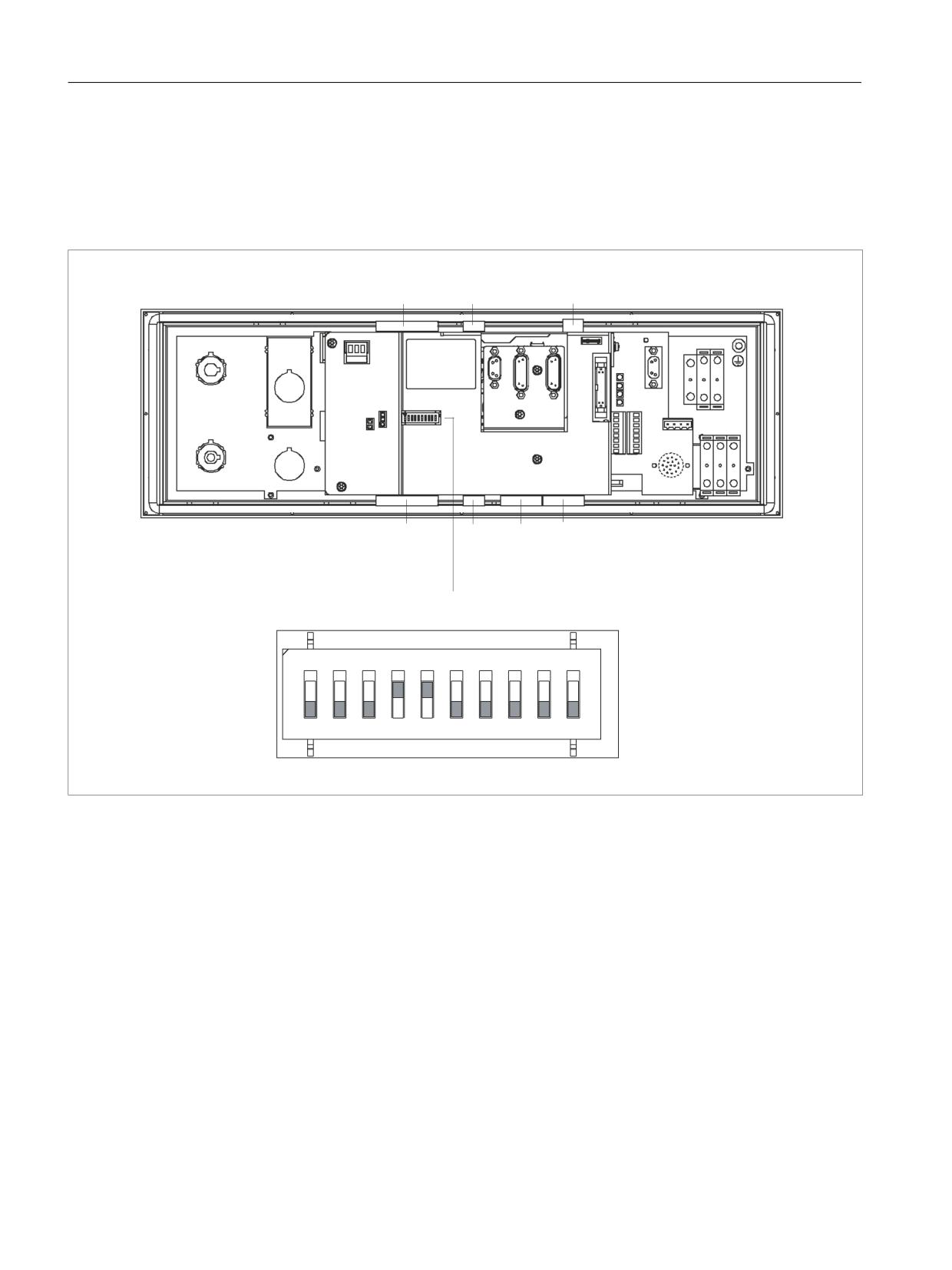
Machine pushbutton panel: MPP 483
9.3 Interfaces
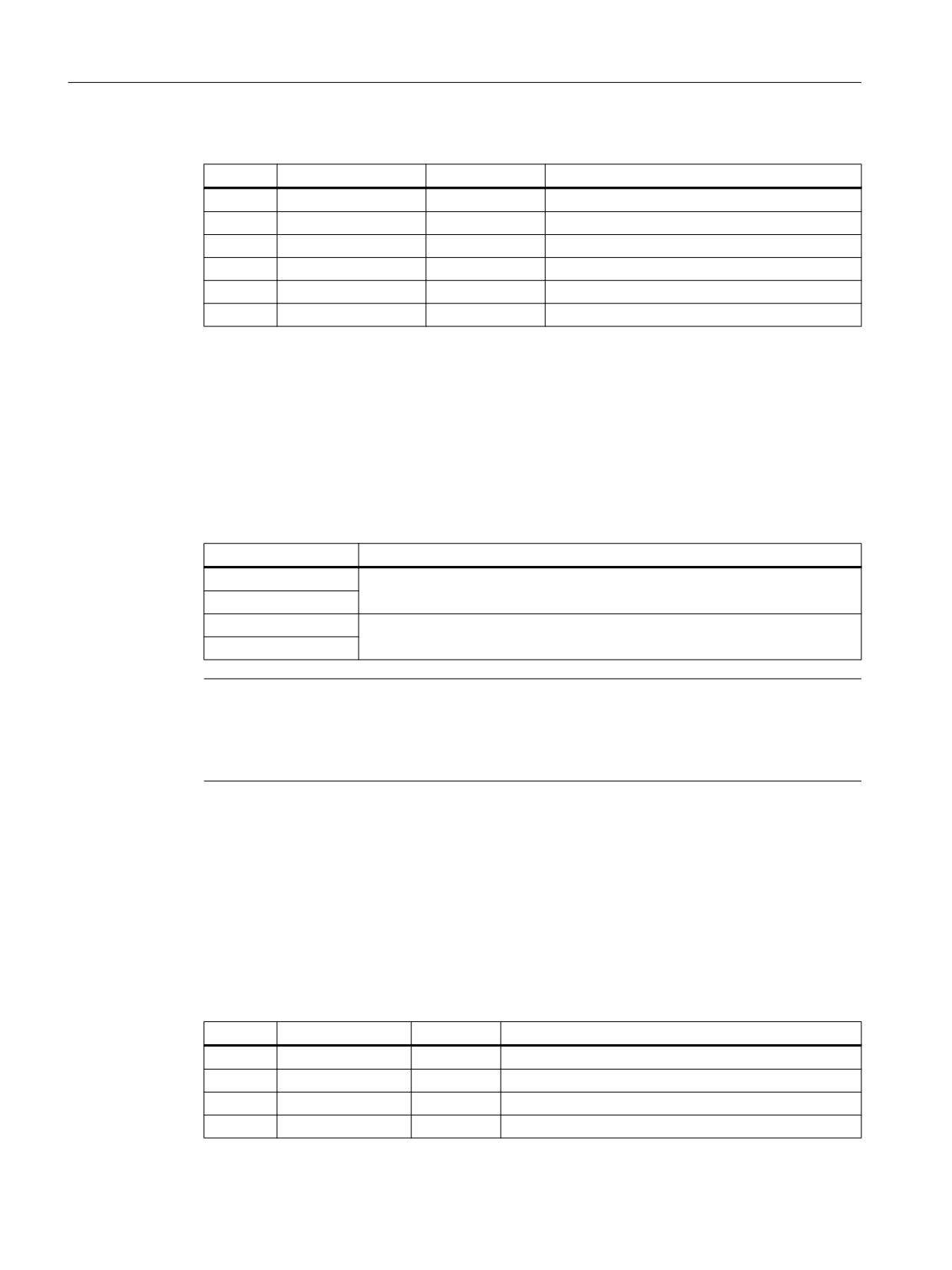
Table 9-22
Assignment of the interface Panel Present X7
Pin
Signal name
Signal type
Meaning
1
PRES
O
"High": Panel (HT 2/8) plugged in
2
N.C.
-
Not connected
3
N.C.
-
Not connected
4
N.C.
-
Not connected
5
N.C.
-
Not connected
6
M
P
Ground
Emergency Stop wiring terminal X8
Connector designa-
X8
tion:
Connector type:
4-pin Phoenix terminal
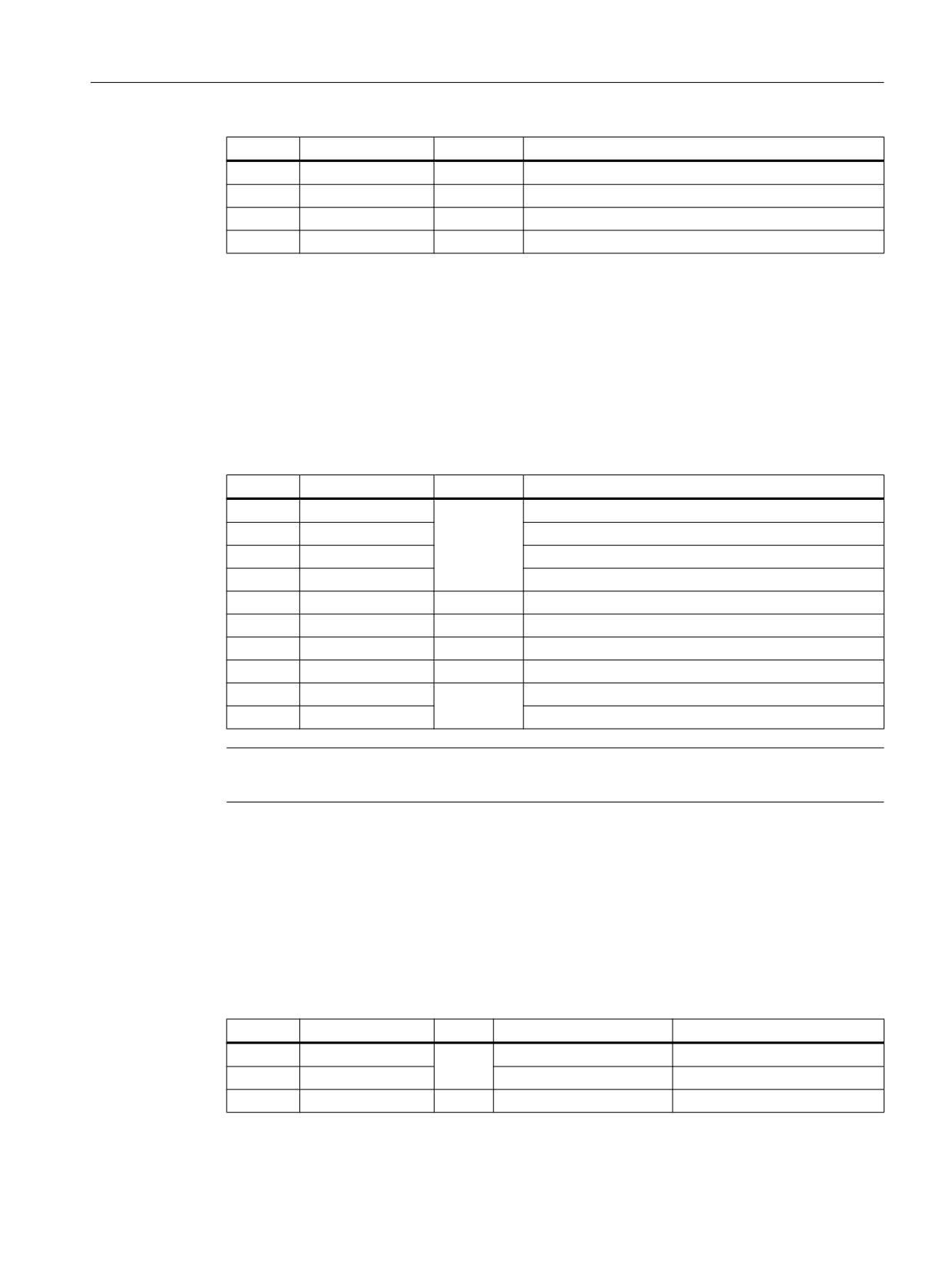
Table 9-23
Assignment of the emergency stop wiring terminal X8
Pin
Protective circuit
1
On-board jumper
between 1 and 2
2
3
On-board jumper
between 3 and 4
4
Note
Use this terminal for simple routing of the emergency stop cables, optional.
The connector is only used to assist looping through. The connected pins 1 and 2 as well as
3 and 4 have no additional function on the connection module.
Enabling X20
Connector designation:X20
Connector type:
MCV 1.5/8-G3.81
Cable length (max.):
30 m
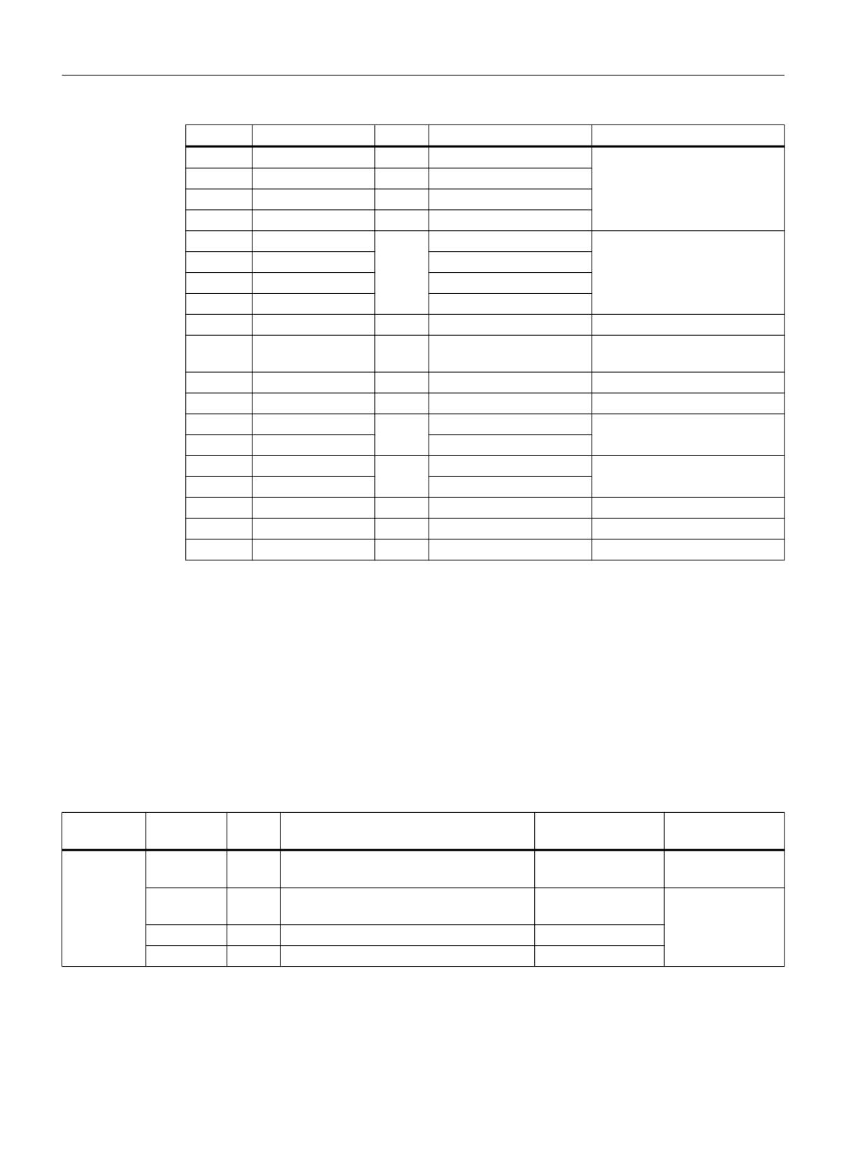
Table 9-24
Enabling X20
Pin
Signal name
Type
Meaning
1
ZUST1P
I
Electronic enabling button 1P
2
ZUST1M
O
Electronic enabling button 1M
3
ZUST2P
I
Electronic enabling button 2P
4
ZUST2M
O
Electronic enabling button 2M
Machine control panels
282
Manual, 03/2016, 6FC5397-1AP40-5BA3
Machine pushbutton panel: MPP 483
9.3 Interfaces
Pin
Signal name
Type
Meaning
5
N.C.
Not connected
6
N.C.
Not connected
7
N.C.
Not connected
8
N.C.
Not connected
Emergency Stop override X21
Connector designation:X21
Connector type:
MCV 1.5/10-G3.81
Cable length (max.):
30 m
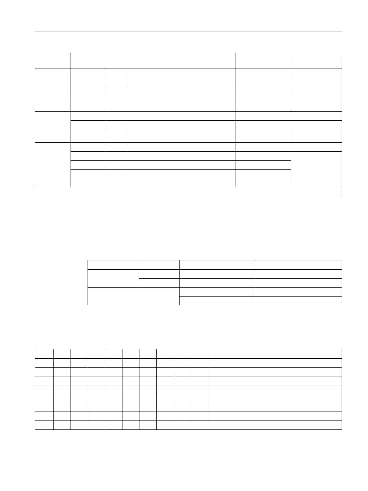
Table 9-25
Emergency Stop override X21
Pin
Signal name
Type
Meaning
1
STOP23
Emergency Stop NC contact 1.1
2
STOP24
Emergency Stop NC contact 1.2
I/O
3
STOP13
Emergency Stop NC contact 2.1
4
STOP14
Emergency Stop NC contact 2.2
5
M
V
6
N.C.
-
Not connected
7
IN_S59
I
Emergency Stop override negated
8
P24_FILT
V
24 V
9
IN_S59_EXT
Key-operated switch actuated
O
10
IN_S62_EXT
Terminating connector plugged in
Note
Emergency stop X21: Supply voltage: 24 VDC; switched current: Max. 500 mA.
Handheld unit connection XS12
Connector designation:XS12
Connector type:
9GX3BXC-T22QF10-0004
Table 9-26
Handheld unit connection XS12
Pin
Signal
Type
Meaning
Function
1
HH_PR_P
+ Present line
I
2
HH_PR_M
- Present line
3
HP24
V
24 V HH for present
Power supply
Machine control panels
Manual, 03/2016, 6FC5397-1AP40-5BA3
283
Machine pushbutton panel: MPP 483
9.3 Interfaces
Pin
Signal
Type
Meaning
Function
4
ZUST2M
O
Enabling button 2M
5
ZUST1P
I
Enabling button 1P
Enabling function
6
ZUST1M
O
Enabling button 1M
7
ZUST2P
I
Enabling button 2P
8
HH_L2.2
HH emergency stop L2.2
9
HH_L2.1
HH emergency stop L2.1
I/O
Emergency stop
10
HH_L1.2
HH emergency stop L1.2
11
HH_L1.1
HH emergency stop L1.1
12
M
V
Ground
Power supply
13
ABS_ST_PRES
I
Terminating connector
Terminating connector plugged
in
14
HH_P24
V
24 V HH supply
Power supply
15
IDENT_B
I/O
Diff Signal Module Addr.
16
TX-
Ethernet Transmit -
O
Ethernet transmitted data
17
TX+
Ethernet Transmit +
18
RX+
Ethernet receive +
I
Ethernet receive data
19
RX-
Ethernet receive -
20
SHIELD
-
Cable shield
21
M
V
Ground
Power supply
22
IDENT_A
I/O
Diff Signal Module Addr.
9.3.3
Connection elements for COM board, customer keys and handheld unit
connection
This table shows plug connection elements for the following modules:
● COM board (COM)
● Customer keys (KT)
● Connection for handheld units (HGA)
Table 9-27
Connection elements
Module
Connector
Units
Terminal element
Connectable cross-
Manufacturer
section (max.)
X10
1
MSTB2,5/3-STZ-5,08,1776168
2.5 mm2
PHOENIX
CONTACT
COM
X20
1
6ES7972-0BA50-0XA0
6ES7972-0BB50-0XA0 *)
X60 / X61
2
6FC9348-7HX
0.75 mm
2
SIEMENS
X70
1
A5E00026403
Machine control panels
284
Manual, 03/2016, 6FC5397-1AP40-5BA3
Machine pushbutton panel: MPP 483
9.3 Interfaces
Module
Connector
Units
Terminal element
Connectable cross-
Manufacturer
section (max.)
X11
1
MSTB2,5/3-ST-5,08,1757022
2.5 mm2
PHOENIX
CONTACT
X20 / X23
2
MC1.5/4-ST-3.81, 1803594
1.5 mm2
KT
X21/X22
2
MC1.5/12-ST-3.81, 1803675
1.5 mm2
X24:A/B
4
MC1.5/8-ST-3.81, 1803633
1.5 mm2
X25: A/B
X1
1
6ES7972-0BA50-0XA0
SIEMENS
HGA hand-
X20/X21
2
MC1.5/8-ST-3.81, 1803633
1.5 mm2
PHOENIX
held unit B-
CONTACT
X22
1
MC1.5/4-ST-5.08, 1836095
1.5 mm2
MPI
X1 / X2
2
6GK1901-1BB10-2AB0
SIEMENS
X7
1
MC1.5/6-STZ-3.81 GY BD1-6.1713198
1.5 mm2
HGA
X8
1
MC1.5/4-STZ-3.81 GY BD1-4.1713185
1.5 mm2
PHOENIX
HT 2/8
CONTACT
X 20
1
MC1.5/8-STZ-3.81 GY BD-1-8, 1713208
1.5 mm2
X 21
1
MC1.5/10-STZ-3.81 GY BD1-10, 1901658
1.5 mm2
*) With PG connection
9.3.4
Settings via DIP switch
The configurations which are available for the MPP 483 are displayed broken down by
PROFIBUS DP and MPI (GD) communication protocols. For PROFIBUS DP, the PROFIBUS
slave ID which has been specified by PI is also named.
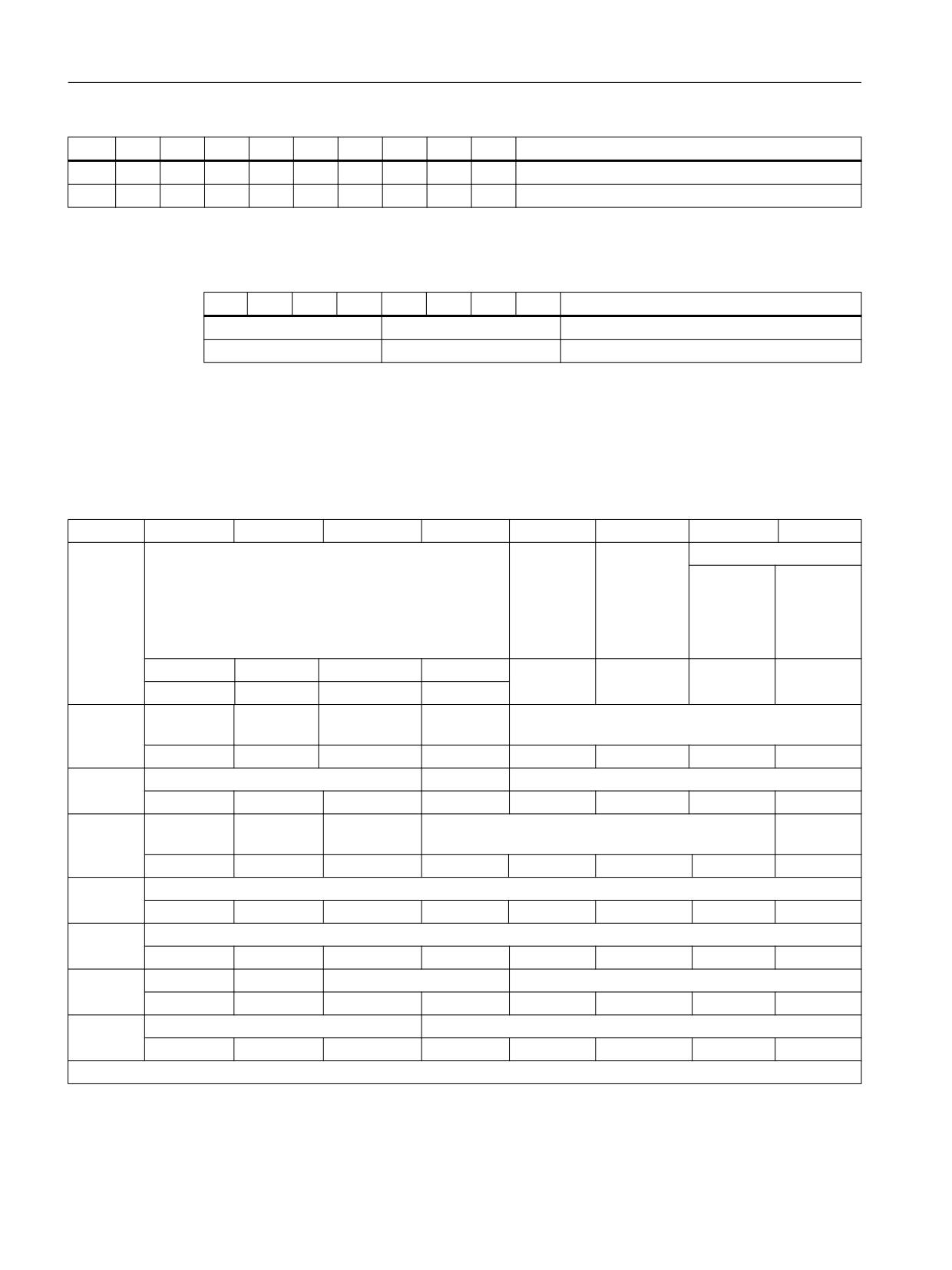
Slave ID
Configuration
IN/OUT
Standard
8/8 bytes
MPI (GD)
Extended standard
12/8 bytes
Standard
14/8 bytes
PROFIBUS DP
8122
Standard + handwheel
14/8 bytes + 2/0 words
Settings for coding switch S3
Table 9-28
Settings for coding switch S3 for PROFIBUS DP
1
2
3
4
5
6
7
8
9
10
Meaning
on
MPP 483 as PROFIBUS slave
off
off
Reserved
off
off
off
off
off
off
off
Bus address: 0
on
off
off
off
off
off
off
Bus address: 1
off
on
off
off
off
off
off
Bus address: 2
on
on
off
off
off
off
off
Bus address: 3
etc.
off
off
on
on
on
on
on
Bus address: 124
Machine control panels
Manual, 03/2016, 6FC5397-1AP40-5BA3
285
Machine pushbutton panel: MPP 483
9.3 Interfaces
1
2
3
4
5
6
7
8
9
10
Meaning
on
off
on
on
on
on
on
Bus address: 125
off
on
on
on
on
on
on
Bus address: 126
Bits 8 and 9 are reserved during PROFIBUS mode and should be assigned "off".
Table 9-29
Module address connection module HT 8
8
7
6
5
4
3
2
1
Meaning
S1
S2
Switch
0 to F
0 to F
Module address
9.3.5
Input / output images
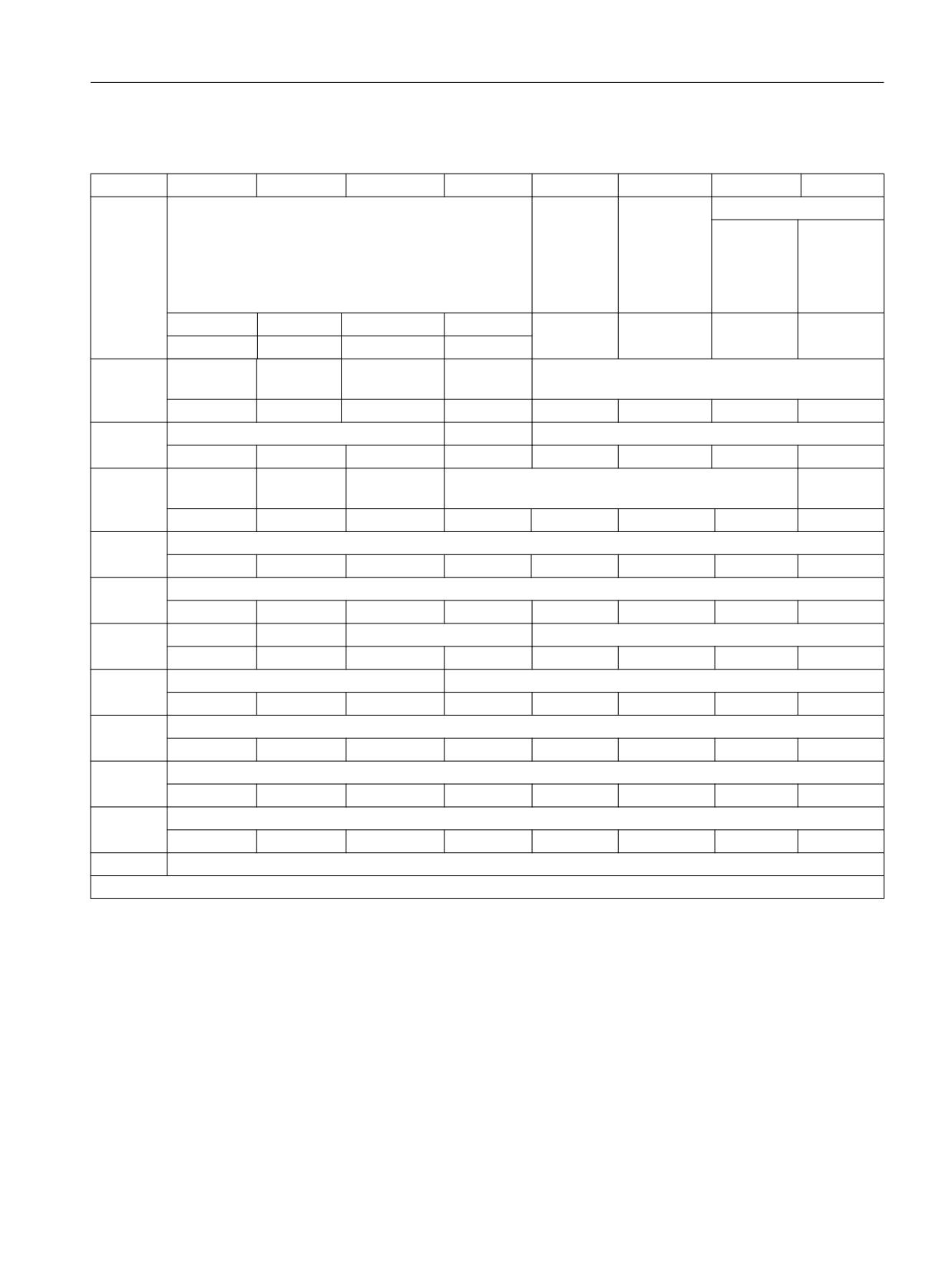
MPI standard input image
Byte
Bit7
Bit6
Bit5
Bit4
Bit3
Bit2
Bit1
Bit0
n+0
BA switch
Function
HG connec-
Emergency stop override
key
tion
S11
S11
HT 2 / HT 8
right-hand
left-hand
XS12:13
side
side
momenta-
momenta-
ry-contact
ry-contact
WS1/4
WS1/3
WS1/2
WS1/1
F21
S62
S60
S59
F16*)
F11*)
F6*)
F1*)
n+1
Customer
Key
Customer
Extension
Customer keys
key
key
key
S15
WS4, pos.0
S14
S51
S4
S3
S2
S1
n+2
Key
SR key
Rapid traverse override
WS4, pos.3
WS4, pos.2
WS4, pos.1
S61
WS5/8
WS5/4
WS5/2
WS5/1
n+3
Extension
Emergency
Customer keys
Extension
key
stop
key
S53
S13
S10
S9
S8
S7
S52
n+4
Direct keys
DT8
DT7
DT6
DT5
DT4
DT3
DT2
DT1
n+5
Direct keys
DT16
DT15
DT14
DT13
DT12
DT11
DT10
DT9
n+6
Extension keys
Spindle override
S58
S57
WS3/8
WS3/4
WS3/2
WS3/1
n+7
Extension keys
Feed override
S56
S55
S54
WS2/16
WS2/8
WS2/4
WS2/2
WS2/1
*) The function keys are not active if WS1 is assigned.
Machine control panels
286
Manual, 03/2016, 6FC5397-1AP40-5BA3
Machine pushbutton panel: MPP 483
9.3 Interfaces
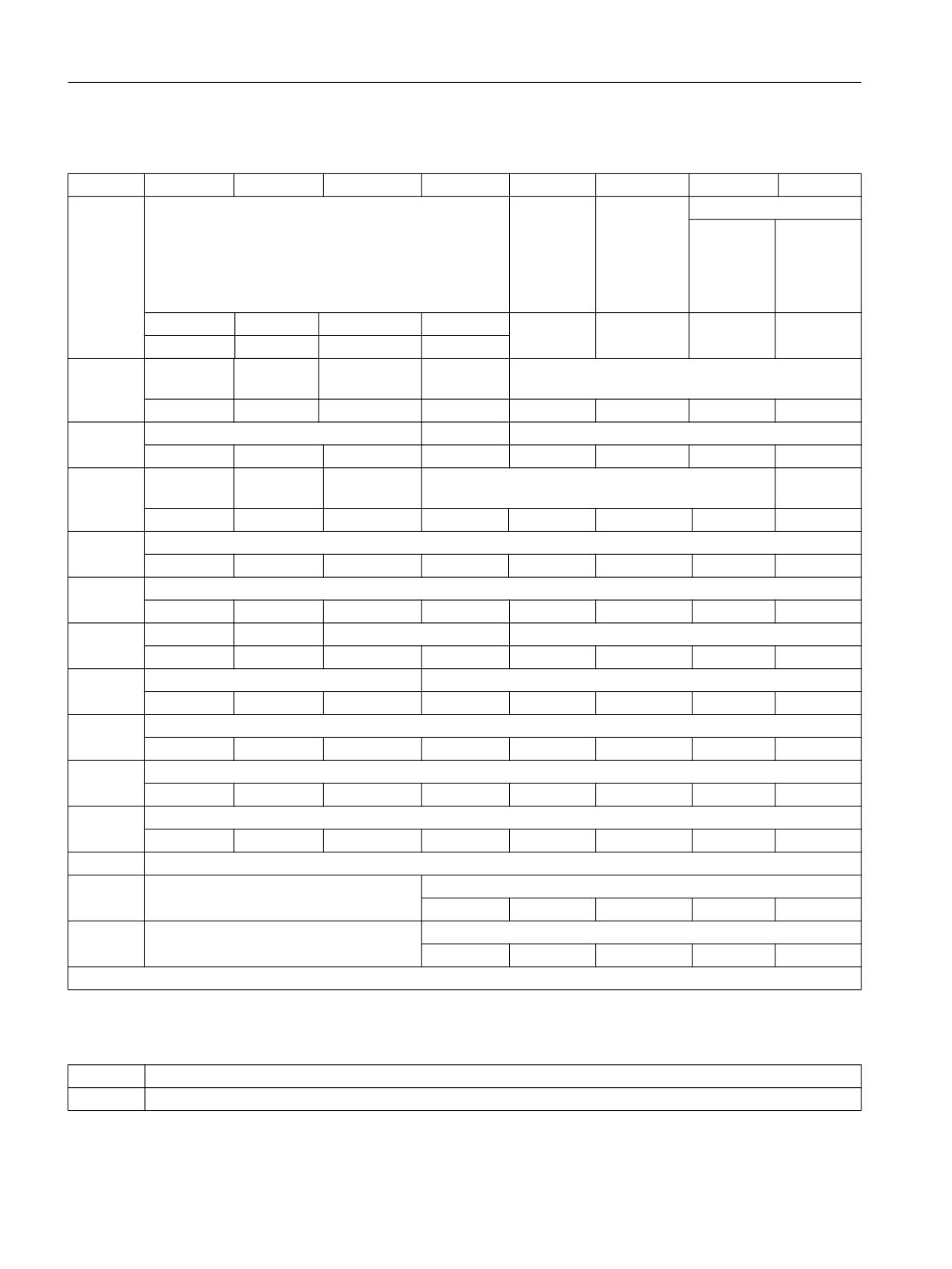
MPI extended input image
Byte
Bit7
Bit6
Bit5
Bit4
Bit3
Bit2
Bit1
Bit0
n+0
BA switch
Function
HG connec-
Emergency stop override
key
tion
S11
S11
HT 2 / HT 8
right-hand
left-hand
XS12:13
side
side
momenta-
momenta-
ry-contact
ry-contact
WS1/4
WS1/3
WS1/2
WS1/1
F21
S62
S60
S59
F16*)
F11*)
F6*)
F1*)
n+1
Customer
Key
Customer
Extension
Customer keys
key
key
key
S15
WS4, pos.0
S14
S51
S4
S3
S2
S1
n+2
Key
SR key
Rapid traverse override
WS4, pos.3
WS4, pos.2
WS4, pos.1
S61
WS5/8
WS5/4
WS5/2
WS5/1
n+3
Extension
Emergency
Customer keys
Extension
key
stop
key
S53
S13
S10
S9
S8
S7
S52
n+4
Direct keys
DT8
DT7
DT6
DT5
DT4
DT3
DT2
DT1
n+5
Direct keys
DT16
DT15
DT14
DT13
DT12
DT11
DT10
DT9
n+6
Extension keys
Spindle override
S58
S57
WS3/8
WS3/4
WS3/2
WS3/1
n+7
Extension keys
Feed override
S56
S55
S54
WS2/16
WS2/8
WS2/4
WS2/2
WS2/1
n+8
Function keys
F8
F7
F6
F5
F4
F3
F2
F1
n+9
Function keys
F16
F15
F14
F13
F12
F11
F10
F9
n+10
Function keys
F25
F24
F23
F22
F20
F19
F18
F17
n+11
Reserve
*) The function keys are not active if WS1 is assigned.
Machine control panels
Manual, 03/2016, 6FC5397-1AP40-5BA3
287
Machine pushbutton panel: MPP 483
9.3 Interfaces
PROFIBUS-DP input image
Byte
Bit7
Bit6
Bit5
Bit4
Bit3
Bit2
Bit1
Bit0
n+0
BA switch
Function
HG connec-
Emergency stop override
key
tion
S11
S11
HT 2 / HT 8
right-hand
left-hand
XS12:13
side
side
momenta-
momenta-
ry-contact
ry-contact
WS1/4
WS1/3
WS1/2
WS1/1
F21
S62
S60
S59
F16*)
F11*)
F6*)
F1*)
n+1
Customer
Key
Customer
Extension
Customer keys
key
key
key
S15
WS4, pos.0
S14
S51
S4
S3
S2
S1
n+2
Key
SR key
Rapid traverse override
WS4, pos.3
WS4, pos.2
WS4, pos.1
S61
WS5/8
WS5/4
WS5/2
WS5/1
n+3
Extension
Emergency
Customer keys
Extension
key
stop
key
S53
S13
S10
S9
S8
S7
S52
n+4
Direct keys
DT8
DT7
DT6
DT5
DT4
DT3
DT2
DT1
n+5
Direct keys
DT16
DT15
DT14
DT13
DT12
DT11
DT10
DT9
n+6
Extension keys
Spindle override
S58
S57
WS3/8
WS3/4
WS3/2
WS3/1
n+7
Extension keys
Feed override
S56
S55
S54
WS2/16
WS2/8
WS2/4
WS2/2
WS2/1
n+8
Function keys
F8
F7
F6
F5
F4
F3
F2
F1
n+9
Function keys
F16
F15
F14
F13
F12
F11
F10
F9
n+10
Function keys
F25
F24
F23
F22
F20
F19
F18
F17
n+11
Reserve
n+12
Feed override
WS2/16
WS2/8
WS2/4
WS2/2"
WS2/1
n+13
Spindle override
WS3/16
WS3/8
WS3/4
WS3/2
WS3/1
*) The function keys are not active if WS1 is assigned.
Optional 4-byte handwheel
n+0
Handwheel 1
n+1
Handwheel 1
Machine control panels
288
Manual, 03/2016, 6FC5397-1AP40-5BA3
Machine pushbutton panel: MPP 483
9.3 Interfaces
n+2
Handwheel 2
n+3
Handwheel 2
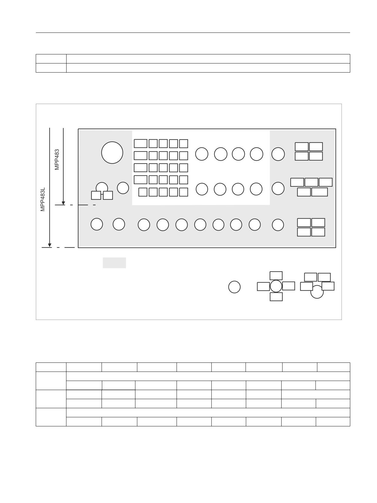
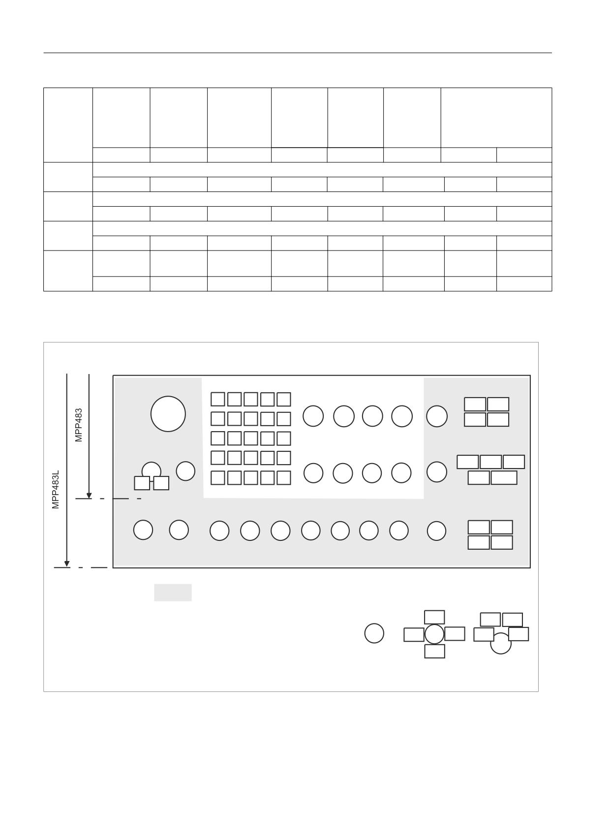
Keyboard layout - input image MPP 483
6SLQGOH RYHUULGH
:6
)
)
)
)
)
29 63
29 63
6
6
6
6
6
6
)
)
)
)
)
29 63
29 63
)
)
)
)
)
)HHG RYHUULGH
:6
6
;6
)
)
)
)
)
29 96
29 96
29 96
6
6
6
6
6
6
)
)
)
)
)
29 96
29 96
6
6
5DSLG WUDYHUVH RYHUULGH
:6
29 (O
29 (,
6
6
6
6
6
6
6
6
29 (,
29 (,
$OWHUQDWLYH HTXLSPHQW RI WKH
$UHD
YDULDEOH DUHD
YDULDEOH HOHPHQWV
7KH HOHPHQWV ZLWKLQ WKH
,WHP
:6
:6
PDUNHG DUHD FDQ EH
6
,WHP
,WHP
:6
:6
LQWHUFKDQJHG DFFRUGLQJ WR WKH
:6
SRVVLEOH HTXLSPHQW YDULDWLRQV
:6
,WHP
Image 9-13 Front view
Output image MPI / PROFIBUS-DP
Byte
Bit7
Bit6
Bit5
Bit4
Bit3
Bit2
Bit1
Bit0
n+0
Customer keys
Hs8
HS7
HS15
HS14
HS4
HS3
HS2
HS1
n+1
Customer keys
HS10
HS9
n+2
Extension keys
H58
H57
H56
H55
H54
H53
H52
H51
Machine control panels
Manual, 03/2016, 6FC5397-1AP40-5BA3
289
Machine pushbutton panel: MPP 483
9.3 Interfaces
n+3
SR key
Feedback
Extension keys E9/E10
for
when S11 is not used
emergency
stop
H61
HS13
H60
H59
n+4
Function keys
HF8
HF7
HF6
HF5
HF4
HF3
HF2
HF1
n+5
Function keys
HF16
HF15
HF14
HF13
HF12
HF11
HF10
HF9
n+6
Function keys
HF24
HF23
HF22
HF21
HF20
HF19
HF18
HF17
n+7
Function
key
HF25
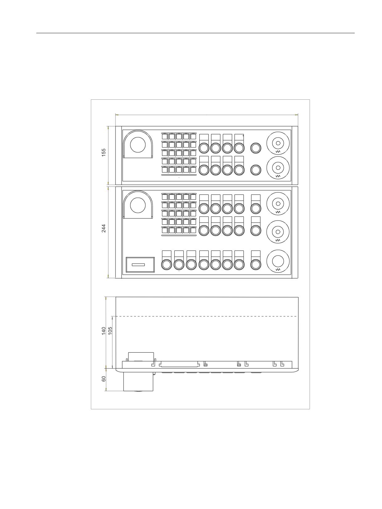
Keyboard layout - output image MPP 483
6SLQGOH RYHUULGH
:6
+)
+)
+)
+)
+)
+6
+6
+6
+6
+6
+6
+)
+)
+)
+)
+)
+)
+)
+)
+)
+)
)HHG RYHUULGH
:6
6
;6
+)
+)
+)
+)
+)
+6
+6
+6
+6
+6
+)
+)
+)
+)
+)
5DSLG WUDYHUVH RYHUULGH
:6
+
+
+
+
+
+
+
+
+
+
$OWHUQDWLYH HTXLSPHQW RI WKH
$UHD
YDULDEOH DUHD
YDULDEOH HOHPHQWV
7KH HOHPHQWV ZLWKLQ WKH
PDUNHG DUHD FDQ EH
LQWHUFKDQJHG DFFRUGLQJ WR WKH
+
:6
SRVVLEOH HTXLSPHQW YDULDWLRQV
:6
Image 9-14 Front
Machine control panels
290
Manual, 03/2016, 6FC5397-1AP40-5BA3
Machine pushbutton panel: MPP 483
9.4 Mounting
9.4
Mounting
Dimensions
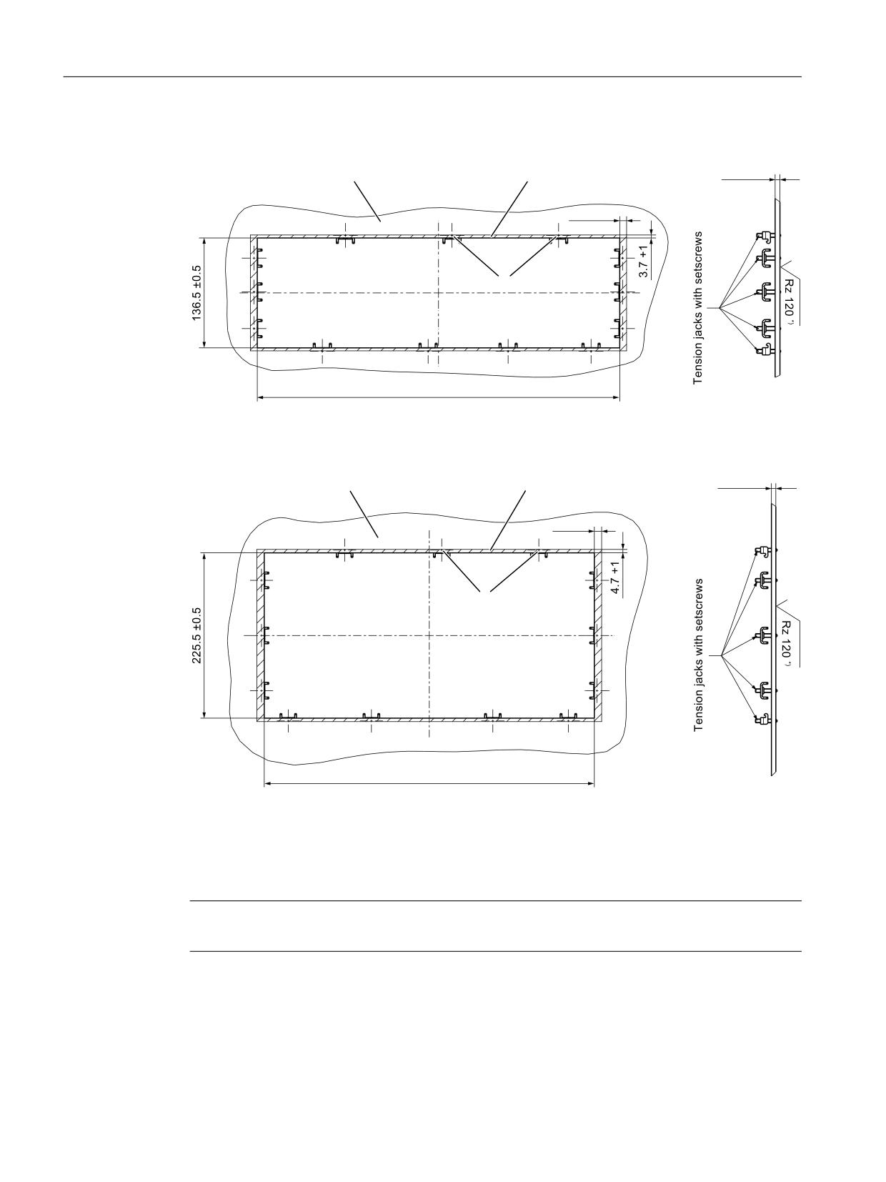
Image 9-15 Dimension drawing for MPP 483 and MPP 483 L
*) The depth of 105 mm is only attainable with a Profibus adapter.
Machine control panels
Manual, 03/2016, 6FC5397-1AP40-5BA3
291
Machine pushbutton panel: MPP 483
9.4 Mounting
Panel cutouts
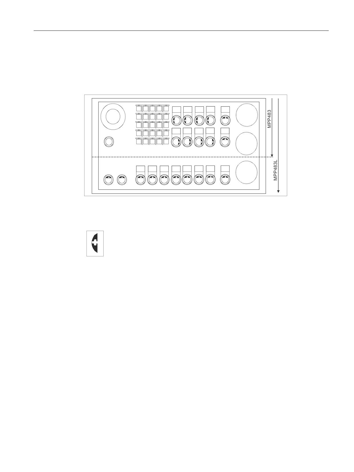
0RXQWLQJ SDQHO
6HDOLQJ DUHD
3UHVVXUH SRLQWV
IRU WHQVLRQ MDFNV
s
,Q WKH VHDOLQJ DUHD
Image 9-16 Panel cutout for MPP 483
0RXQWLQJ SDQHO
6HDOLQJ DUHD
3UHVVXUH SRLQWV
IRU WHQVLRQ MDFNV
s
,Q WKH VHDOLQJ DUHD
Image 9-17 Panel cutout for MPP 483 L
The MPP 483 is attached to the rear side of the operator panel using 13 tension jacks
(contained in the delivery kit). The tightening torque is 0.4 mm.
Note
The clearance to the next MPP (above and below) must be a minimum of 18 mm.
Mounting position
The mounting position is max. 60° to the vertical.
Machine control panels
292
Manual, 03/2016, 6FC5397-1AP40-5BA3
Machine pushbutton panel: MPP 483
9.4 Mounting
For mounting positions greater than 60°, a fan must also be installed to keep the ambient
temperature of the machine control panel constantly below 55° C.
Mounting position of LEDs
Image 9-18 Mounting position for MPP 483 / MPP 483 L LEDs
Marking of the anode connection:
Insert +polarity of the LED in key at the side marked
Machine control panels
Manual, 03/2016, 6FC5397-1AP40-5BA3
293
Machine pushbutton panel: MPP 483
9.4 Mounting
Installing Profibus adapter
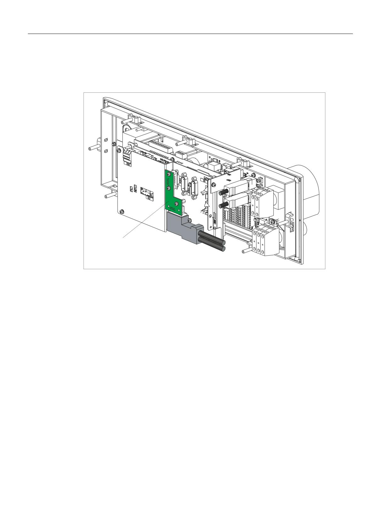
If no handwheels are connected, the installation depth can be reduced from 140 mm to 105
mm. For this, insert the PCB Profibus adapter (1) according to the figure.
Image 9-19 Installing Profibus adapter
Changing the lamps on illuminated keys
1. Use a screwdriver to pull the key cap forward and off.
2. Use lamp remover LZ6 to lever out the key carrier.
3. Change the lamp using service tool LZ6 or a suitable insulating tube
4. Reinstall the key carrier and key cap in reverse order.
Lamp remover LZ6 is not a SIEMENS product. It can be obtained from the Schlegel company.
Georg Schlegel GmbH & Co. KG
Am Kapellenweg
Phone.: 0 73 71 / 502-0
88525 Dürmentingen
Fax: 0 73 71 / 502 49
Germany
E-mail: info@schlegel.biz
Machine control panels
294
Manual, 03/2016, 6FC5397-1AP40-5BA3

Machine pushbutton panel: MPP 483
9.4 Mounting
Changing the lamps on pilot lamps
1. Use a screwdriver to pull the calotte and name bearing element forward and off.
2. Change the lamp using the lamp remover of service tool LZ6 or a suitable insulating tube
3. Reinstall the calotte and name bearing element.
Note
When using LEDs, make sure that they are connected with the correct polarity (see Fig.:
"Mounting position of LEDs" in Section: "Mounting")
Mounting additional control elements
1. If necessary, unscrew the blank plug.
2. Place the contact maker on the socket and insert the lamp if required.
3. Insert pushbutton through front panel and screw on cap nut (by several turns).
4. Press pushbutton on contact maker. Note the position of the twist protection device!
5. Screw down cap nut (tightening torque 0.8 Nm).
Insert slide-in labels
1. Create the slide-in label (see Section: "Accessories and spare parts" → "Labeling the slide-
in labels").
2. Pull protective films off slide-in slot.
3. Guide in the slide-in labels (labeling facing operator side).
4. Align text in window.
Note
Slide in the labels when the MPP is not yet installed.
Changing a contact maker
1. Loosen cap nut off pushbutton until just in front of contact maker.
2. Pull the pushbutton and the contact maker approximately 3 mm out of the fixture (the
locating pin of the pushbutton must be freed).
3. Remove the LED.
4. Change the contact element, remove defective contact maker from fixture and press new
contact maker onto fixture.
5. Insert pushbutton into aperture and partially screw on cap nut.
6. Press pushbutton on contact maker until it snaps in. Note the position of the snap nose!
7. Screw down cap nut (tightening torque 0.8 Nm).
Machine control panels
Manual, 03/2016, 6FC5397-1AP40-5BA3
295
Machine pushbutton panel: MPP 483
9.5 Connecting
9.5
Connecting
9.5.1
MPP 483
Connecting the 24 V supply
The 24 V supply is connected via a 3-pin terminal block at connector X10 and X11 to the rear
of the machine control panel (see Figure: "Rear side of MPP 483 with interfaces" in Section:
"Interfaces" → "Overview").
The protective ground is secured to the M5 bolt (see Figure: "MPI connection").
NOTICE
Damage to the device caused by unfused power supplies
The 24 VDC supply must always be grounded and designed as "Protective Extra-Low
Voltage" (PELV) - protection by function low voltage with safe isolation!
Emergency stop circuit connection
The emergency stop circuit connections are shown in figures "MPI connection" and
"PROFIBUS DP connection."
Machine control panels
296
Manual, 03/2016, 6FC5397-1AP40-5BA3
Machine pushbutton panel: MPP 483
9.5 Connecting
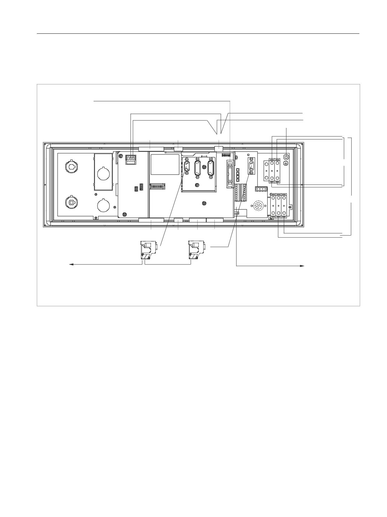
MPI connection
Connection of X1 (HGA) to X20 (COM board) and to the control
'LUHFW FRQWURO NH\V
3&8
0
3
3(
(PHUJ VWRS FLUFXLW
.7 ;
.7 ;
.7 ;
(PHUJ VWRS FLUFXLW
;
:6
&20
6
6
&20 ;
+
6
+
&20
+
;
;
;
+
(PHUJ VWRS FLUFXLW
+
+
+
&20
+
+
&20
6
:6
&20 6
;
(PHUJ VWRS FLUFXLW
;
+*$
6
;
;
;6
(PHUJ VWRS FLUFXLW
.7 ;
.7 ;
.7 ;
.7 ;
(PHUJ VWRS FLUFXLW
03, EXV
(QDEOH
(PHUJ VWRS FLUFXLW Z R +*$
(PHUJ VWRS FLUFXLW ZLWK +*$
Image 9-20 MPI connection
Machine control panels
Manual, 03/2016, 6FC5397-1AP40-5BA3
297
Machine pushbutton panel: MPP 483
9.5 Connecting
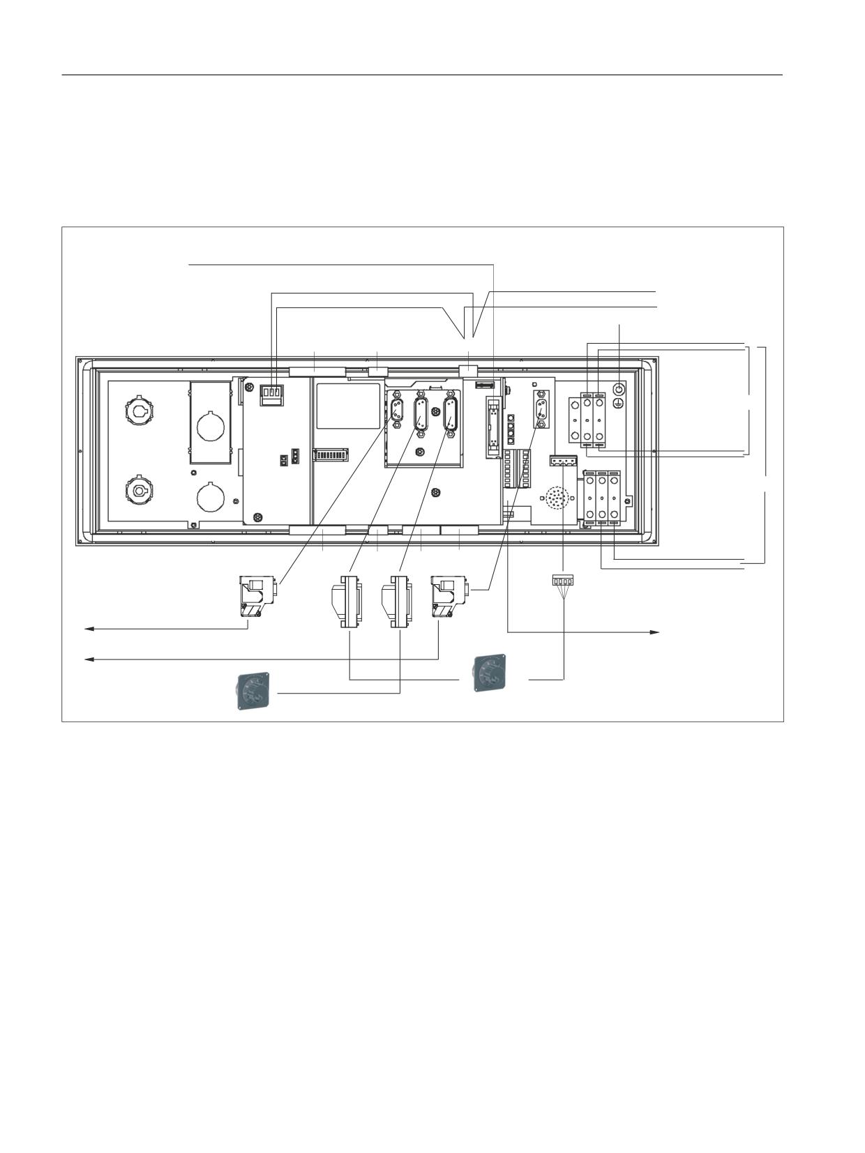
PROFIBUS DP connection
● DP connection via X20 (COM board) to the control
● MPI connection via X1 (HGA) to the PCU of the panel
● Handwheel 1 from X60 (COM board) to connection X22 (HGA) for the handheld unit
'LUHFW FRQWURO NH\V
3&8
0
3
3(
(PHUJ VWRS FLUFXLW
.7 ;
.7 ;
.7 ;
(PHUJ VWRS FLUFXLW
;
:6
&20
6
6
&20 ;
+
6
+
&20
+
;
;
;
+
(PHUJ VWRS FLUFXLW
+
+
+
&20
+
+
&20
6
:6
&20 6
;
(PHUJ VWRS FLUFXLW
;
+*$
6
;
;
;6
(PHUJ VWRS FLUFXLW
.7 ;
.7 ;
.7 ;
.7 ;
(PHUJ VWRS FLUFXLW
352),%86 '3
(QDEOH
03, EXV
+DQGZKHHO
RU +*$
(PHUJ VWRS FLUFXLW Z R +*$
+DQGZKHHO
(PHUJ VWRS FLUFXLW ZLWK +*$
Image 9-21 PROFIBUS DP connection
Machine control panels
298
Manual, 03/2016, 6FC5397-1AP40-5BA3
Machine pushbutton panel: MPP 483
9.5 Connecting
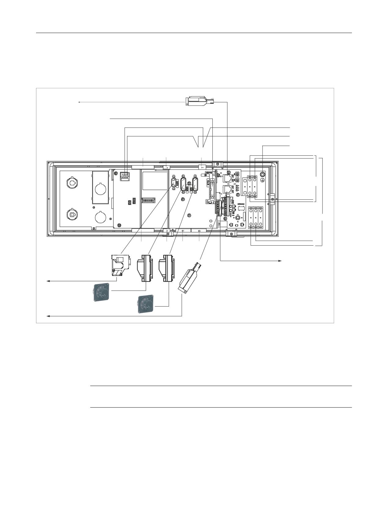
Connection for HT 8
● DP connection via X20 (COM board) to the control
● Ethernet connection X1 / X2
(WKHUQHW
'LUHFW FRQWURO NH\V
3&8
0
3
3(
.7 ;
.7 ;
.7 ;
(PHUJ VWRS FLUFXLW
(PHUJ VWRS FLUFXLW
&20 6
:6
;
&20 ;
6
6
;
&20 6
;
&20
;
;
(PHUJ VWRS FLUFXLW
:6
6
(PHUJ VWRS FLUFXLW
&20 ;
&20
;6
6
;
;
(PHUJ VWRS FLUFXLW
.7 ;
.7 ;
.7 ;
.7 ;
(PHUJ VWRS FLUFXLW
(QDEOH
3URILEXV 03,
+DQGZKHHO
+DQGZKHHO
(PHUJ VWRS FLUFXLW Z R +*$
(WKHUQHW
(PHUJ VWRS FLUFXLW ZLWK +*$
Image 9-22 Ethernet connection
Individual wiring connection
Selector switches and individual contacts are connected in accordance with the customer-
specific links required (see figure in Section: "Customer keys (KT) module").
Note
Supply voltages for inputs and outputs must always be grounded!
Machine control panels
Manual, 03/2016, 6FC5397-1AP40-5BA3
299
Machine pushbutton panel: MPP 483
9.5 Connecting
9.5.2
COM board
The COM board provides communication via the bus and forms the interface to the
superordinate system.
The parameters are set on coding switch S3.
.7 ;
.7 ;
.7 ;
;
:6
6
&20
6
&20 ;
+
6
+
&20
+
;
;
;
+
+
+
+
&20
:6
+
+
&20
6
&20 6
;
;
+*$
6
;
;
;6
.7 ;
.7 ;
.7 ;
.7 ;
&20 6
21
Image 9-23 Coding switch S3
9.5.3
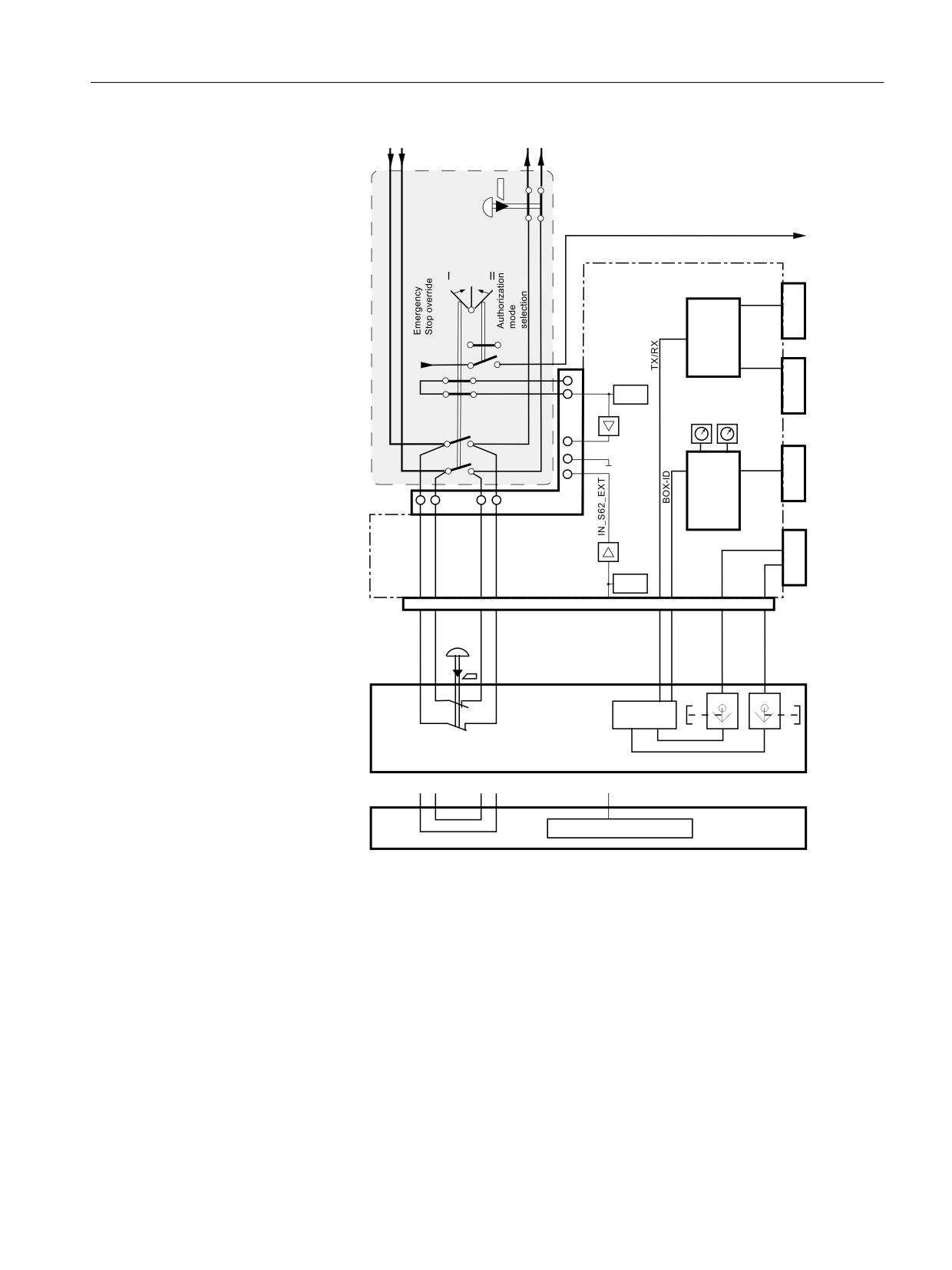
Handheld unit connection HT 8 with emergency stop override
The connection for handheld units (HGA) of the HT 8 has four function complexes:
● Two-channel version of enabling function
● Three-port Ethernet switch
Machine control panels
300
Manual, 03/2016, 6FC5397-1AP40-5BA3
Machine pushbutton panel: MPP 483
9.5 Connecting
● Connection of HT 8
● Module address
WARNING
Danger of death if the enabling button is not DIN-conform
It is the user's responsibility to ensure that the enabling button or the enable control is
implemented according to DIN EN 60204-1, Section 9.2.6.3, and the enabling button,
when released or pushed down, stops dangerous movements reliably.
Emergency stop override S11
● Implemented as pushbutton or keyswitch
● Pushbutton pressed or keyswitch, left probing
- "Emergency stop override" of the handheld unit connection → query via input S59
- Interruption of the power supply for the handheld unit connection when actuated
● Keyswitch, right probing: Unassigned function → query via input S60
6
+7
&LUFXLW
&LUFXLW
6
+7
&LUFXLW
&LUFXLW
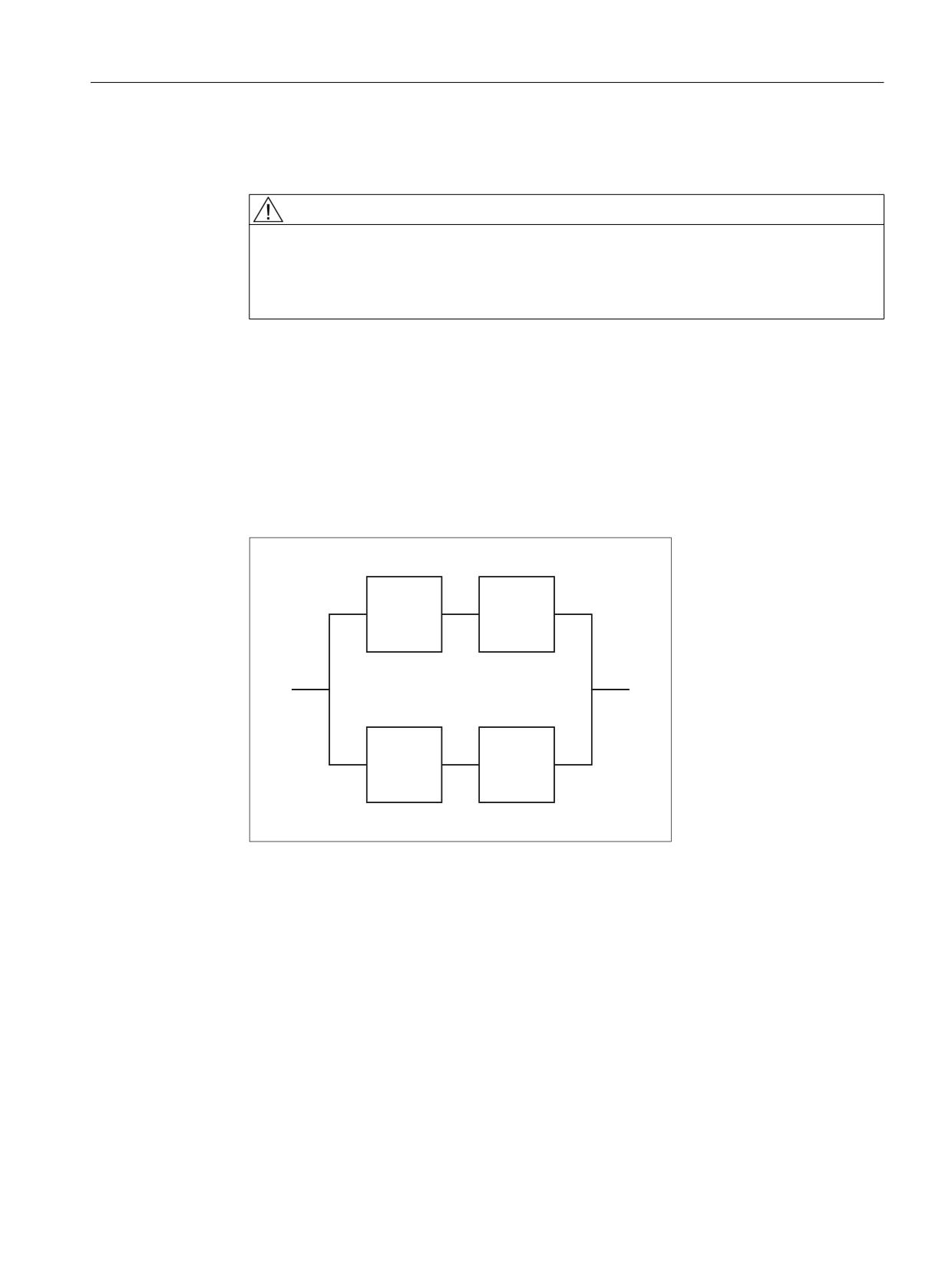
Image 9-24
2-channel architecture of the emergency stop override contacts
With regard to their accidental failure, the contacts of the emergency stop override safety
function form a 2-channel architecture together with the emergency stop button on the HT 8.
In addition to the B10d value of the emergency stop button, the B10d value of S11 must also be
taken into consideration for the assessment in both emergency stop circuits.
Machine control panels
Manual, 03/2016, 6FC5397-1AP40-5BA3
301
Machine pushbutton panel: MPP 483
9.5 Connecting
The diagnostics for the contacts of S11 is performed on the HT 8 together with the diagnostics
of the emergency stop button.
WARNING
Danger of death caused by failure of the "emergency stop" safety function
The user must ensure that the emergency stop override is implemented with the S11 button
in accordance with the safety goals required by the risk analysis of the machine. Actuation
of the emergency stop override results in failure of the emergency stop safety function on the
HT 8. The user must implement suitable organizational and/or technical procedures for this
in order to achieve the safety goals.
As a technical measure, the signaling contacts on the S11 emergency stop override: 31/32
and 61/62 can be used to trigger an "emergency stop" by the PLC after a monitoring time has
expired (maximum five minutes) (see Remark 1 in the following figure). However, this
measure alone does not satisfy the requirements of Category 3, PL d according to
EN ISO 13849-1:2008.
If the risk analysis of your machine has shown that the technical measure for monitoring the
emergency stop override (S11) is not sufficient, the signaling contacts 31/32 and 61/62 of
S11 can be evaluated, e.g. by a safe PLC or the SPL of the SINUMERIK 840D sl. The
requirements of category 3, PL d according to EN ISO 13849-1:2008 can be met with this
measure.
For this purpose, the user must wire these contacts accordingly.
All other functions can be found in the figure.
Machine control panels
302
Manual, 03/2016, 6FC5397-1AP40-5BA3
Machine pushbutton panel: MPP 483
9.5 Connecting
6\VWHP (PHUJHQF\ 6WRS
6
,QSXW PRGH VHOHFWLRQ
3&% .7 ;
%
OHIW
ULJKW
PRPHQWDU\
PRPHQWDU\
FRQWDFW
6
FRQWDFW
O
;
3&% KDQGKHOG XQLW FRQQHFWLRQ
7; 5;
(WKHUQHW
6ZLWFK
;
7; 5;
3
Q
0RGXOH DGGUHVV
6
6
;
,1B6
B(;7
0
35(6
%2; ,'
SUHVHQW
;
LGHQWLILFD
WLRQ
;
Q
;V
+DQGKHOG XQLW
0DLQERDUG
(PHUJHQF\ 6WRS
(QDEOLQJ EXWWRQV
7HUPLQDWLQJ FRQQHFWRU
SDUW RI WKH 033
ZLWK
7HUPLQDWLQJ FRQQHFWRU FRGLQJ
KDQGKHOG XQLW FRQQHFWLRQ
6LJQDO WR WKH 3/&
7ULJJHUV WLPH PRQLWRULQJ ,I DIWHU WKH PRQLWRULQJ WLPH KDV H[SLUHG PD[LPXP PLQ WKH VLJQDO OHYHO LV VWLOO
ORZ RU RSHQ WKHQ WKH 3/& PXVW LQLWLDWH DQ (0(5*(1&< 2))
1RW DYDLODEOH IRU YHUVLRQ 6 DV SXVKEXWWRQ
Image 9-25 Handheld unit connection HT 8
9.5.4
Customer keys
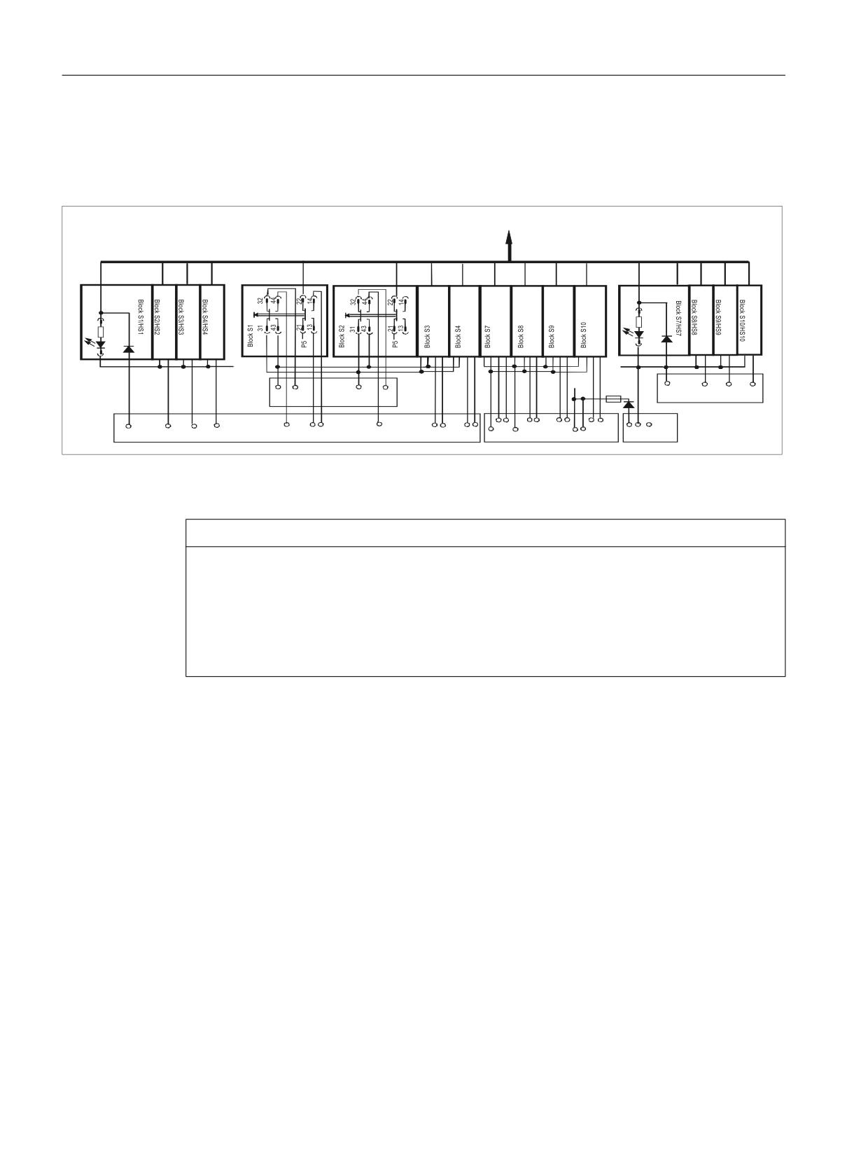
The customer keys (KT) module links the operator panel, handheld unit connection and COM
board.
Machine control panels
Manual, 03/2016, 6FC5397-1AP40-5BA3
303
Machine pushbutton panel: MPP 483
9.5 Connecting
The inputs for handheld unit connection and extension keys are opto-decoupled.
The outputs belonging to these are issued by high-side drivers.
The floating individual contacts of function keys S1 ... S4 and S7 ... S10 are shown in the figure.
7R 3/&
P
P
P
P
J
J
J
J
J
J
J
J
P
P
P
P
P
6
6
;
;
+6
+6
;
;
N
K
N
K
N
K
N K
D E
F G
H
I
D
E F G
D E F
G
D E F
G
D
E
F
G
D E F
G
D E F
G
D E F
G
N
K
N
K
N K N K
0
0
9
)
;
;
;
;
;
Image 9-26 Individual wiring of the customer keys (a, b, …, m designate IN and OUT of the individual blocks)
NOTICE
Damage to pushbutton contacts
When using an external 24 V encoder supply, always protect the key contacts against
overload in the individual wiring with an external fuse for L+ with the following properties:
- circuit breaker of characteristic A, 1.6 A.
If you use the encoder supply X20:A15/A16 or VS1/VS2 of the ET200S block 4/8 F DI 24
VDC PROFIsafe, the external fuse can be omitted.
Machine control panels
304
Manual, 03/2016, 6FC5397-1AP40-5BA3
Machine pushbutton panel: MPP 483
9.5 Connecting
9.5.5
Circuits and wiring
External control of signaling lamps
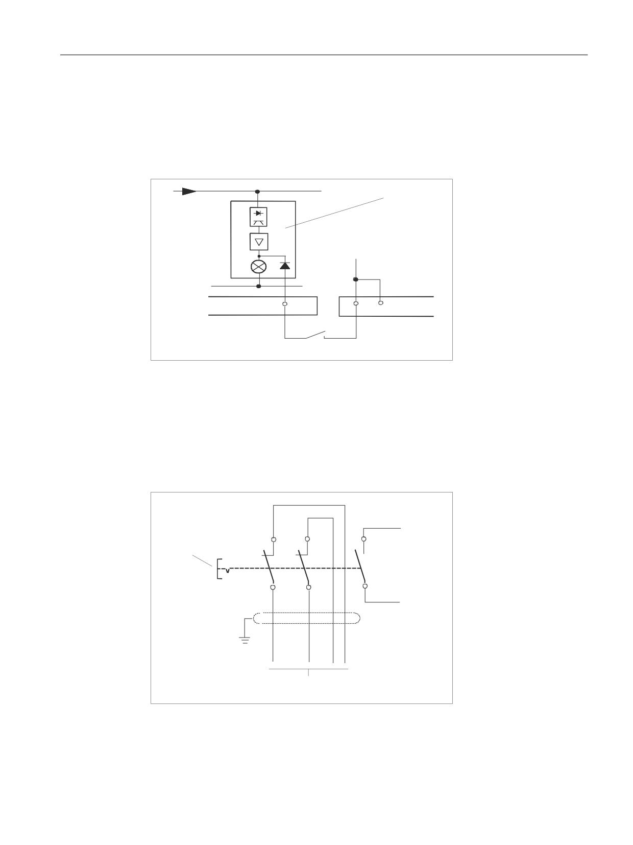
The following circuit diagram relates to the lights in HS1 to HS4 and HS7 to HS10.
3
+6Q
0
;
;
;
(1)
Block Sn
(2)
External contact
Image 9-27 External control of signaling lamps
Circuit for emergency stop button
.7 ;
%
3
(1)
Emergency stop button S13
(2)
Emergency stop of the machine control
Image 9-28 Circuit for emergency stop button
Machine control panels
Manual, 03/2016, 6FC5397-1AP40-5BA3
305
Machine pushbutton panel: MPP 483
9.5 Connecting
Extension keys connection
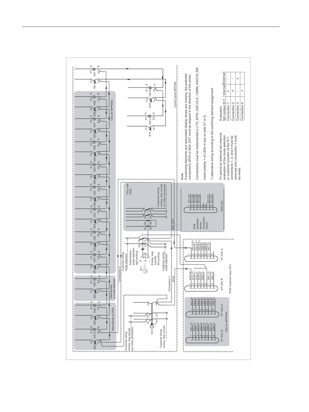
Image 9-29 Extension keys connection
Machine control panels
306
Manual, 03/2016, 6FC5397-1AP40-5BA3
Machine pushbutton panel: MPP 483
9.6 PROFIBUS communication
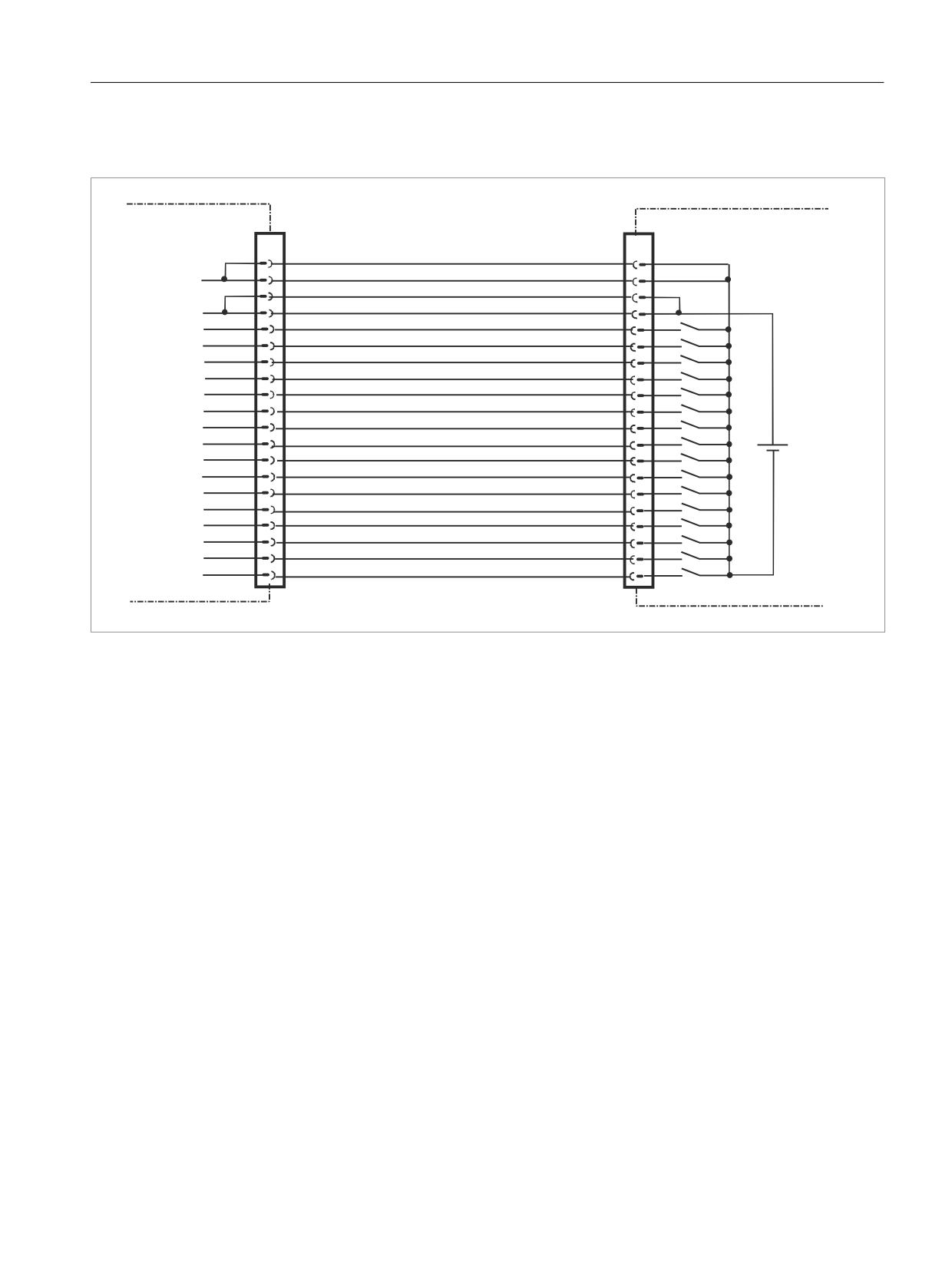
Direct key connection
&20 ERDUG
23
;
)
)
)
)
)
)
)
)
9s
)
)
)
)
)
)
)
)
Image 9-30 Direct key connection
Customer function S11
The NC-NO combination 3SB34 03-0A is right probing and a customer function of the S11.
The NO contact is wired on delivery and can be queried through the MPP 483. The probing
function facilitates mode selection.
If an external evaluation of both contacts is required, the internal wiring on the NO contact
1.3/1.4 of the S 11 must be removed (see Fig.: "Extension keys connection" in this section).
● Remove connection 1 and connection 4
● If connection 2 exists, wire the connection of S11:1.3 to S13:1.4
9.6
PROFIBUS communication
9.6.1
Prerequisites
The assignment and quantity structure of PROFIBUS mode are shown in section: "Interfaces"
→ "Input/output images".
Machine control panels
Manual, 03/2016, 6FC5397-1AP40-5BA3
307
Machine pushbutton panel: MPP 483
9.6 PROFIBUS communication
PROFIBUS mode also offers the following functions:
● Connection of two handwheels
●
5-position spindle override
Prerequisites
The following components are needed as prerequisites for adding a DP slave MPP to the
hardware configuration:
● SIMATIC STEP 7 as of Version 5.4, Service Pack 4
● Toolbox 840D sl as of Version 2.6
Hardware configuration
The DP slave MPP is shown in SIMATIC STEP 7 in the hardware catalog of “HW Config” under
the following path:
Profile: Standard
PROFIBUS DP > Other field devices > NC/RC > Motion Control > SINUMERIK MPP
If the module is not displayed, the GSD file must be installed. To do this, in "HW config" use
menu command
Tools > Install new GSD file.
Note
The GSD file of the DP slave MCP is located on the Toolbox CD in the directory:
...\8x0d\GSD\MPP
9.6.2
Configuring the DP slave MPP 483
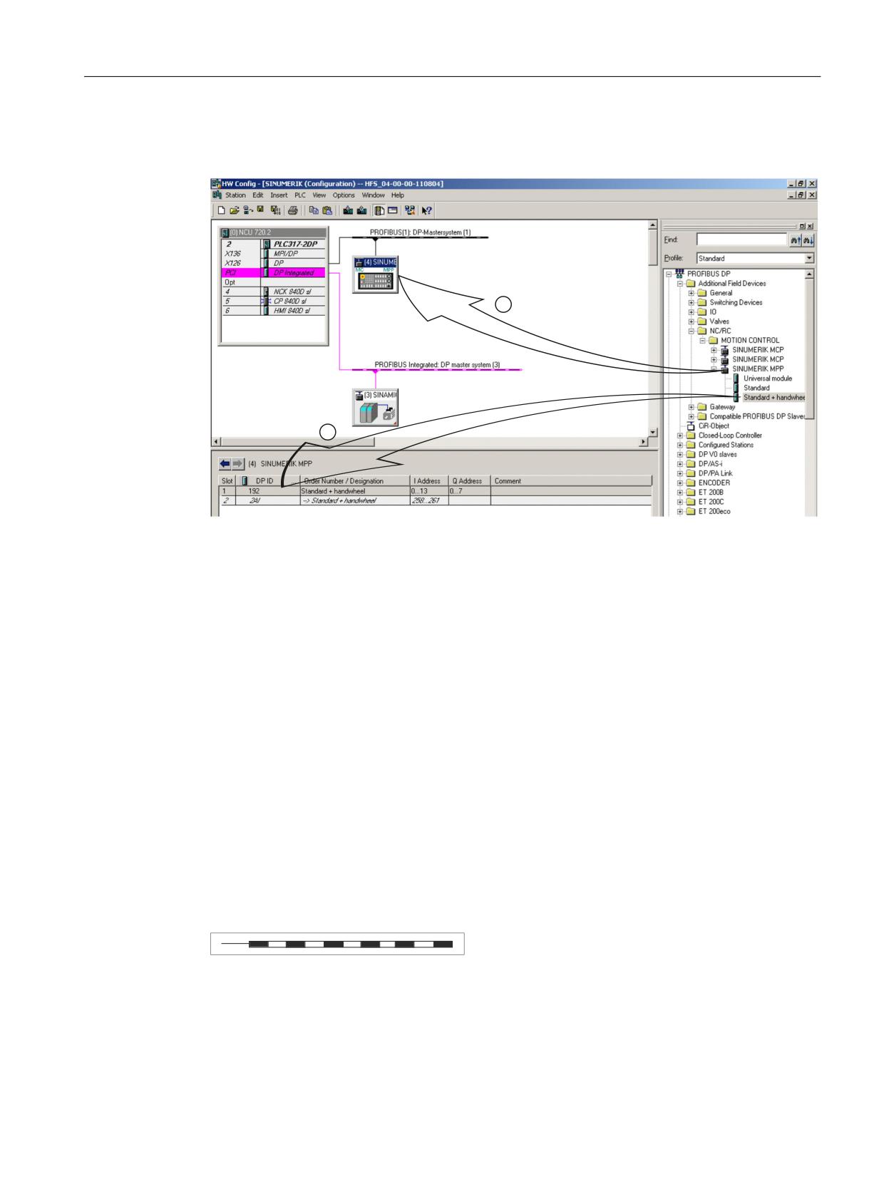
This section describes how to configure a DP slave MPP with reference to the hardware
configuration for a SIMATIC S7 project shown in the figure by way of example.
The hardware configuration has the following modules:
● SIMATIC Station 300 with SINUMERIK 840D sl
● SINUMERIK MPP with module: Standard+Handwheel
Procedure
Configuring the DP slave MPP as an S7 project involves the following steps:
1. Add the DP slave MPP to the configuration ①.
2. Set the PROFIBUS address.
Machine control panels
308
Manual, 03/2016, 6FC5397-1AP40-5BA3
Machine pushbutton panel: MPP 483
9.6 PROFIBUS communication
3. Add the appropriate module to the DP slave MPP depending on the required functions
②.
4. Set the I/O addresses for the individual slots.
Image 9-31 Configuring the DP slave MPP 483
Requirements: S7 project
The following status is required for the S7 project to which the DP slave MPP is to be added:
● The S7 project has been created.
● A SIMATIC 300 station with SINUMERIK controller has been defined.
Adding a DP slave MPP
To add a DP slave MPP to the configuration, open the hardware catalog using the menu
command View > Catalog.
The DP slave MCP can be found at profile: Standard
PROFIBUS DP > Other field devices > NC/RC > Motion Control > SINUMERIK MPP
Click with the left mouse button on the DP slave MPP (SINUMERIK MPP) in the hardware
catalog and drag it onto the DP master system in the station window by holding down the left
mouse button.
The DP master system is displayed in the station window with the following symbol:
Machine control panels
Manual, 03/2016, 6FC5397-1AP40-5BA3
309

Machine pushbutton panel: MPP 483
9.6 PROFIBUS communication
When you release the left mouse button, the DP slave MPP is added to the configuration.
Note
As you drag the DP slave the cursor appears as a circle with a slash through it. When the
cursor is positioned exactly over the DP master system, it changes to a plus sign, and the DP
slave can be added to the configuration.
PROFIBUS parameters
As soon as you have inserted MPP DP slave into the configuration, the "Properties -
PROFIBUS Interface SINUMERIK MPP" dialog box is displayed.
Dialog: Properties - PROFIBUS Interface SINUMERIK MPP
Tab card: Parameters
Address: <PROFIBUS address>
Button: "Properties..."
Dialog: PROFIBUS properties
Tab card: Network settings
Data transfer rate: 12 Mbaud
Profile: DP
OK
OK
The following PROFIBUS parameters must either be set or verified:
● PROFIBUS address
● Data transfer rate
● Profile
Note
No automatic comparison of the PROFIBUS address!
The PROFIBUS address of the DP slave MPP set in the S7 project must match the
PROFIBUS address set on the module (coding switch S3) (see Section: "Initialization")
Adding a module
The active functions and hence the number of user data elements to be transferred are chosen
by selecting the appropriate pre-configured module. The following modules are available in
HW Config under "SINUMERIK MPP":
● Universal module (not applicable)
● Standard
● Standard + handwheel
Machine control panels
310
Manual, 03/2016, 6FC5397-1AP40-5BA3
Machine pushbutton panel: MPP 483
9.7 Maintenance and Service
Setting the I/O addresses
If you add a module to slot 1 of the DP slave MPP, the input/output addresses are automatically
assigned by STEP 7.
Double clicking with the left mouse button on a slot opens the "Properties - DP Slave" dialog
box. The starting addresses for the I/O data for the slot can be set here.
9.6.3
PLC user program
If the MPP is connected via PROFIBUS DP, the basic PLC program does not check for module
failure.
In this case the MPP is monitored by a standard mechanism to monitor the active DP slave:
● PLC operating system
● PROFIBUS controller
If a failure of a DP slave MPP is detected, the PLC defaults to STOP.
Customized response
The following organization blocks can be added to the PLC user program to customize the
response to a DP slave MPP failure:
● OB 82: Diagnostics interrupt
● OB 86: Rack failure
Please refer to the corresponding SIMATIC literature for details of linking organization blocks
and evaluating diagnostic data.
9.7
Maintenance and Service
Cleaning the device
Use a soft cloth moistened either with water or a mild cleaning agent to clean the housing and
operator control elements of the machine control panel.
Checking the device
In order to prevent foreign bodies or liquids entering the machine control panel, regularly check
the device
● that all the housing screws are in place and tight
● for damage to the housing
● for damage to the cable cover or cable entry
Machine control panels
Manual, 03/2016, 6FC5397-1AP40-5BA3
311
Machine pushbutton panel: MPP 483
9.8 Diagnostics
Protect the device from environmental effects
Protect the machine control panel against
● direct solar radiation and heat sources
● mechanical vibration and shock
● dust
● moisture, and
● strong magnetic fields
Checking the emergency stop button
Check the emergency stop button regularly to ensure that it functions correctly.
9.8
Diagnostics
9.8.1
LED displays
LEDs H1 to H5 on the COM board provide information about the following states:
Diagnostics
H1
H3
H4
H5
Power On
Lights up red
Lights up green
Lights up or-
Lights up red/off
ange
The LEDs light up for approx. 4 s.
GD communication
Off
Lights up green
Flashes orange
Lights up red
(80 Hz)
There is no PROFIBUS com-
Lights up red
Lights up green
Off
Flashes green
munication.
(bus error)
(approx. 25 Hz)
MPP is configured as PROFI-
Off
Lights up green
Off/orange
Lights up green
BUS slave and with cyclic data
exchange.
Fatal error LED display
flashes red
flashes green
flashes orange
flashes green
For fatal software errors and incorrect DIP switch settings, the LEDs
flash very quickly.
LED H2 is reserved for service and is always off.
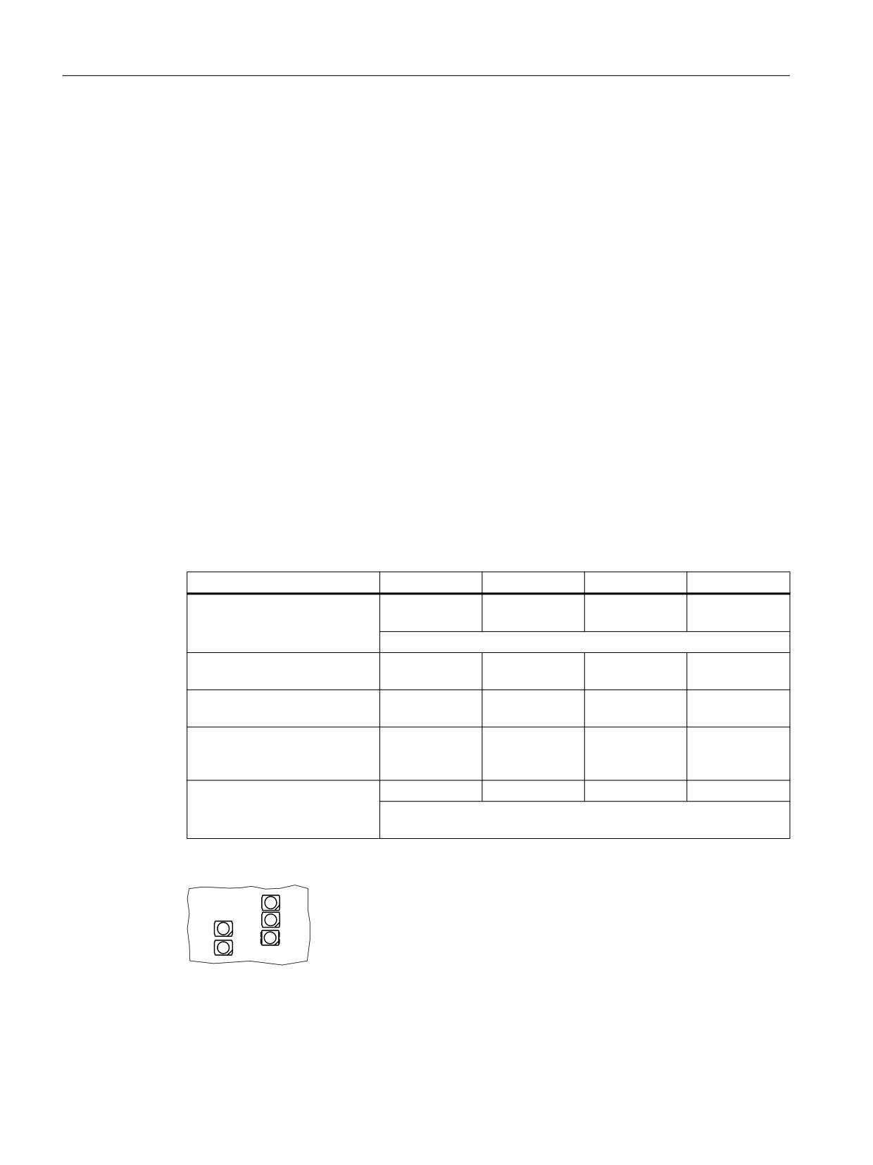
+
+
+
+
+
Image 9-32 Arrangement of the LEDs on the COM board
Machine control panels
312
Manual, 03/2016, 6FC5397-1AP40-5BA3
Machine pushbutton panel: MPP 483
9.8 Diagnostics
9.8.2
Output functions
Preconditions
● The MPP is presently booting.
● The MPP is not communicating with the control system/ PROFIBUS master, i.e. all of the
LEDs in the keys are flashing.
In this state, the output functions described in the following can be sequentially called.
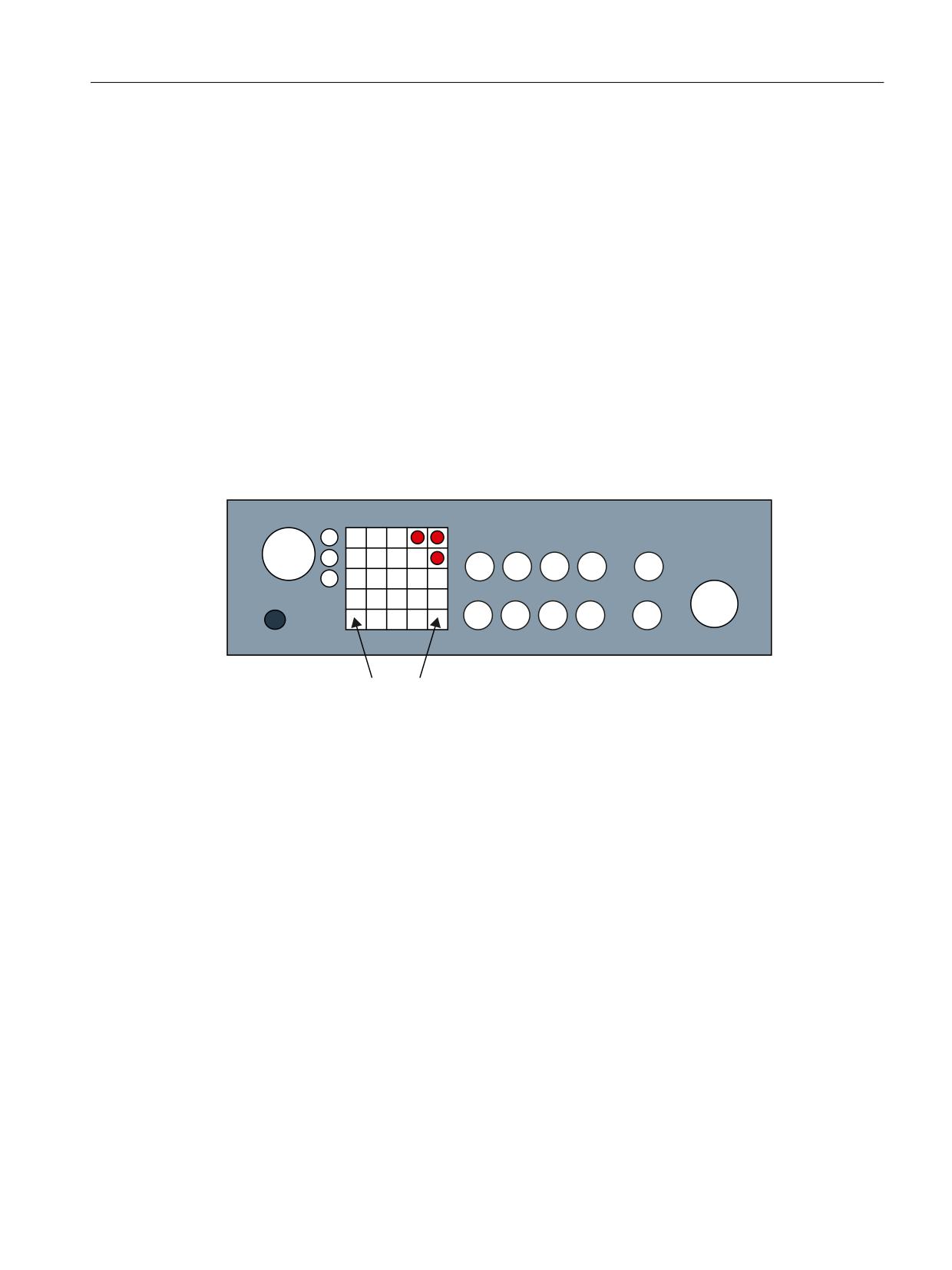
1. Software version
Simultaneously press the "F21" and "F25" keys.
The software version is output using three digits. The individual digits are expressed in the
binary format by the number of LEDs that are on (bright) in the first 3 "LED lines" on the MPP.
The least significant bit position is at the right.
)
)
①
1. Digit of the software version
②
2. Digit of the software version
③
3. Digit of the software version
Image 9-33 Example: Output of the actual software version "03.01.00.00"
2. Output of the bus address
Keep the "F21“ and "F25" pressed, and in addition, press the "F22“ key.
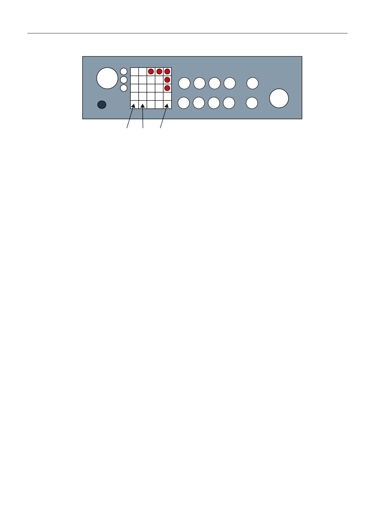
The actual bus address of the MPP is also output in the binary format by the number of LEDs
in the keys that are switched on:
PROFIBUS: Value range 0 … 126
MPI: Value range 0 … 15
Machine control panels
Manual, 03/2016, 6FC5397-1AP40-5BA3
313
Machine pushbutton panel: MPP 483
9.8 Diagnostics
)
)
)
① Ones position of the bus address
② Tens position of the bus address
③ Hundreds position of the bus address
Image 9-34 Example: Output of PROFIBUS address "117"
9.8.3
Key test
Preconditions
● The MPP is presently booting.
● The MPP is not communicating with the control system/ PROFIBUS master, i.e. all of the
LEDs in the keys are flashing.
In this state, the operating functions described in the following can be executed in the test
mode.
Test mode
● Activation: Press the "F1" key.
● Automatic deactivation: No operator control was pressed in the last 3 seconds.
● Manual deactivation: Simultaneously press the "F1" and "F5" keys.
Operating functions
● Function of the function keys and their associated LEDs:
When pressing a function key, the associated LED is switched on.
● Function of the rotary switch
Each time the rotary switch is turned, an LED is switched on in sequence in the form of a
running light.
● Function of the key-operated switch:
When the key-operated switch is turned, positions 0 - 3 are displayed by 0 up to three LEDs.
Machine control panels
314
Manual, 03/2016, 6FC5397-1AP40-5BA3
Machine pushbutton panel: MPP 483
9.9 Technical data
9.9
Technical data
9.9.1
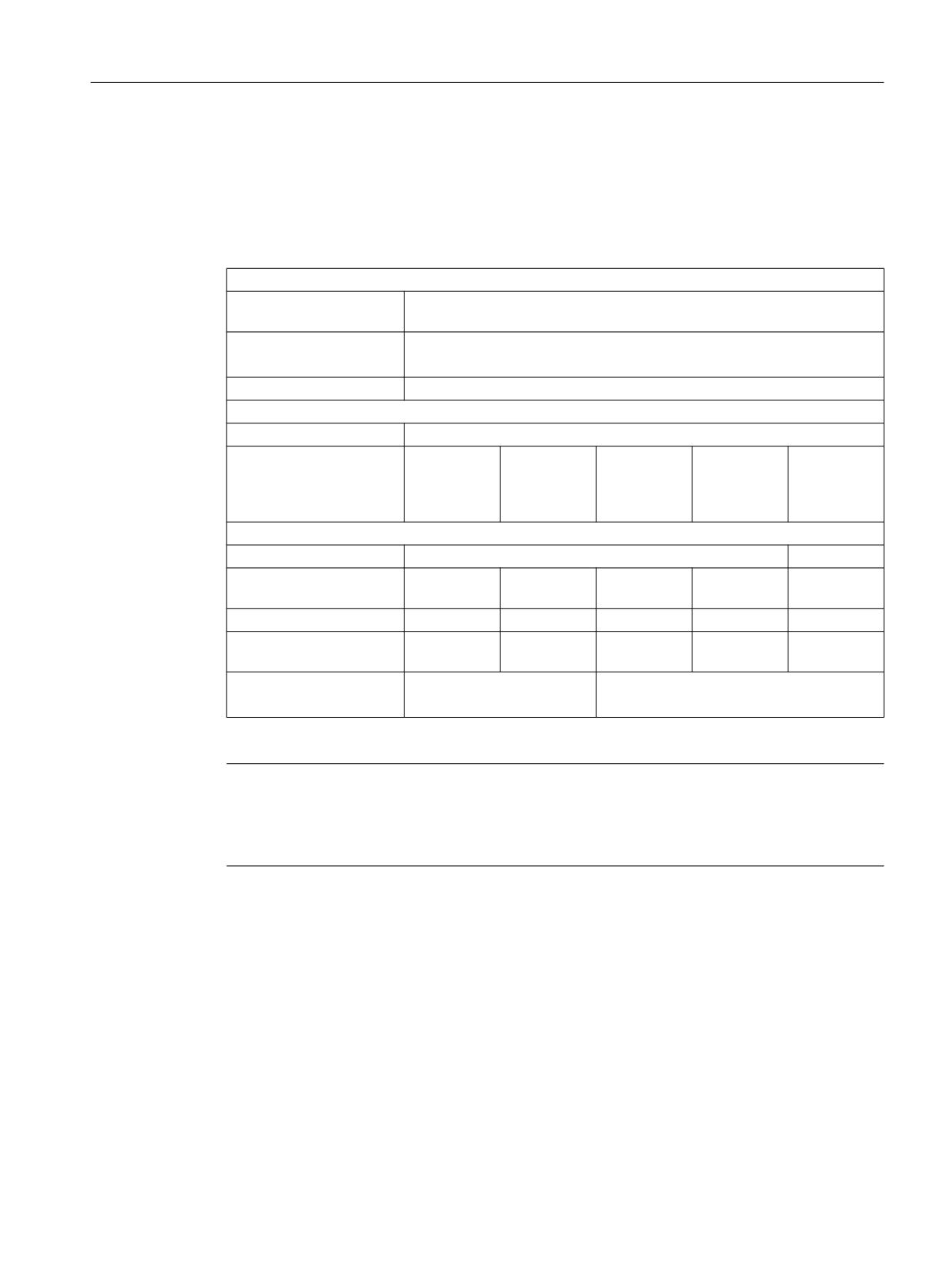
MPP 483
Safety
Safety class according to
III; PELV
EN 50178
Degree of protection ac-
Front side: IP54
cording to EN 60529
Rear: IP10A
Approvals
CE / UL
Electrical data
Input voltage
24 V DC
Power consumption,
Boards:
Lamps:
Handheld
Handwheels:
Total:
max.
LED
unit:
12 W
8.8 W
2 x 0.9 W
35 W
12 W
Mechanical data
Dimensions (mm)
Weight:
Height:
Width:
Depth (front):
Mounting
depth:
MPP 483
155
483
60
140 / 105 *)
Approx. 3 kg
MPP 483 L
244
483
60
140 / 105 *)
Approx. 4.5
kg
Tightening torques, max.
Tension jack screws: 0.4 Nm
M4 screws: 1.8 Nm
M3 screws: 0.8 Nm
M5 screws: 3 Nm
*)
When a PROFIBUS adapter is used
Note
Information about the climatic and mechanical environmental conditions is contained in the
associated section under:
"General notes and interconnection" → "Operational planning".
Machine control panels
Manual, 03/2016, 6FC5397-1AP40-5BA3
315
Machine pushbutton panel: MPP 483
9.9 Technical data
9.9.2
Input/output interface of individual wiring
Button contact maker
Table 9-30
Contacts with floating outputs S1 to S4; S7 to S10 (NC contact or NO contact)
AC
DC
Rated insulation voltage
Ue
50 V
50 V
Rated operating current
Ie
2 A
Rated operating current at 24 V
Ie
2 A
Min. rated operating current at 5 V
Imin
1 mA
Volume resistance
< 20 mΩ
Switching capacity
10 le
1.1 le
Selector switch
Table 9-31
Contacts with floating outputs WS1 / 9-11, 13, 15
AC
DC
Max. operating voltage
Ue
50 V
50 V
Switching capacity with resistive load
10 A
Switching capacity with inductive load
> 2 A
Switching capacity at 24 V with resistive load
10 A
Switching capacity at 24 V with inductive load
6 A
Rated values for arc-free switching at 24 V
0.3 A
0.22 A
Emergency stop button S13
Rated voltage
24 VDC
Current magnitude, max.
3 A
Current magnitude, min.
1 mA
Switching capacity
DC 13 according to EN 60947-5-1
Conditional rated short-circuit current
10 A gL/gG according to EN 60947-5-1
B10d
500 000
Note
The quantitative assessment of the emergency stop safety function must be based on the
B10d values corresponding to the used standards (e.g. ISO 13849-1) under consideration of
the respective application (frequency of the actuation, service life, diagnostics by the evaluation
unit, etc.). The B10d values only apply when the technical properties of the emergency stop
button are taken into account.
Machine control panels
316
Manual, 03/2016, 6FC5397-1AP40-5BA3
Machine pushbutton panel: MPP 483
9.9 Technical data
SR mushroom-head button S61
Table 9-32
Contacts with floating outputs
Usage category
AC
DC
(EN 60947-5-1)
Rated operational voltage
Ue
24 V
24 V
AC-12
le
10 A
AC-15
le
6 A
Switching capacity
DC-12
le
10 A
DC-13
le
3 A
Min. rated operating current at 5 V
Imin
1 mA
For further parameters, see pushbutton and indicator light SIGNUM 3SB3
B10d
500 000
Note
The quantitative assessment of the emergency stop safety function must be based on the
B10d values corresponding to the used standards (e.g. ISO 13849-1) under consideration of
the respective application (frequency of the actuation, service life, diagnostics by the evaluation
unit, etc.). The B10d values only apply when the technical properties of the contact block are
taken into account.
Emergency stop override S11
Table 9-33
Contacts with floating outputs
Usage category
AC
DC
(EN 60947-5-1)
Rated operational voltage
Ue
24 V
24 V
AC-12
le
10 A
AC-15
le
6 A
Switching capacity
DC-12
le
10 A
DC-13
le
3 A
Min. rated operating current at 5 V
Imin
1 mA
For further parameters, see pushbutton and indicator light SIGNUM 3SB3
B10d
500 000
Note
The quantitative assessment of the emergency stop safety function must be based on the
B10d values corresponding to the used standards (e.g. ISO 13849-1) under consideration of
the respective application (frequency of the actuation, service life, diagnostics by the evaluation
unit, etc.). The B10d values only apply when the technical properties of the contact block are
taken into account.
Machine control panels
Manual, 03/2016, 6FC5397-1AP40-5BA3
317
Machine pushbutton panel: MPP 483
9.9 Technical data
Inputs
The inputs are opto-decoupled.
Table 9-34
S51 ... S62, S14, S15, emergency stop S13
Status
Switching voltage
Remark
Number
15
Input characteristics
curve
following IEC61131,
type 1
Rated value
+ 24 VDC
H signal
Signal level
+15 V to +30 V
Rated value
0 V or open
L signal
Signal level
-3 V to +5 V
In a group of
1
Cable length
Max. 50 m
AWG 16
Encoder power supply
18.5 V to 30 V
LED outputs
Table 9-35
S51 ... S61, S14, S15, emergency stop HS13
Status
Switching voltage
Switching current
Number
14
Load voltage 2P24
20.4 V ... 28.8 V
Rated value
+24 VDC
0.5 A
H signal
Signal level min.
Ue - 0.16 V
Max. 0.7 A / output
L signal
Max. signal level
2 V (idling)
0.3 mA
Short-circuit protection
Yes
Typ. activation threshold
1.1 A
RMS short-circuit current
0.5 A
Electrical isolation
No
In a group of
1
Output total current
Max. 3 A
Cable length
Max. 50 m
AWG 16
Handheld unit connection XS12
The currents depend on the connected handheld unit.
The internal connecting cables of the handheld unit connection B-MPI are designed for a rated
voltage of 24 VDC and 2 A.
The internal connecting cables of the handheld unit connection HT 8 are designed for a rated
voltage of 24 VDC and 0.5 A.
Machine control panels
318
Manual, 03/2016, 6FC5397-1AP40-5BA3
Machine pushbutton panel: MPP 483
9.10 Accessories and spare parts
9.10
Accessories and spare parts
9.10.1
Overview
Numerous spare parts and accessories are available for the MPP 483.
Contact your Siemens service center to order accessories and spare parts.
9.10.2
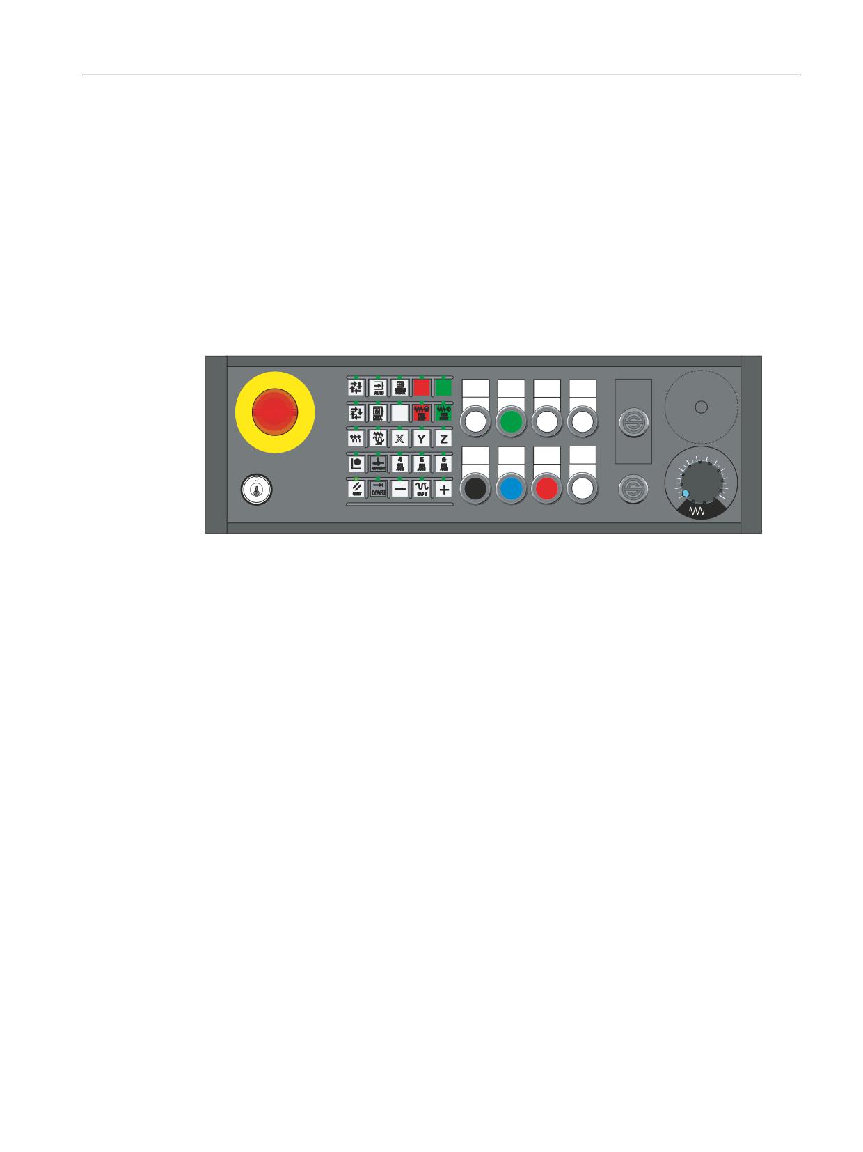
Labeling the slide-in labels
NC
NC
Machine on
Initial state
Start
Acknowledge
Stop
Start
fault
Next-
Axes
Machine off
Stop after
Immediate
Lock/release
50
70
end of cycle
Stop
protective
30
80
doors
10
90
6
100
2
110
0
120
%
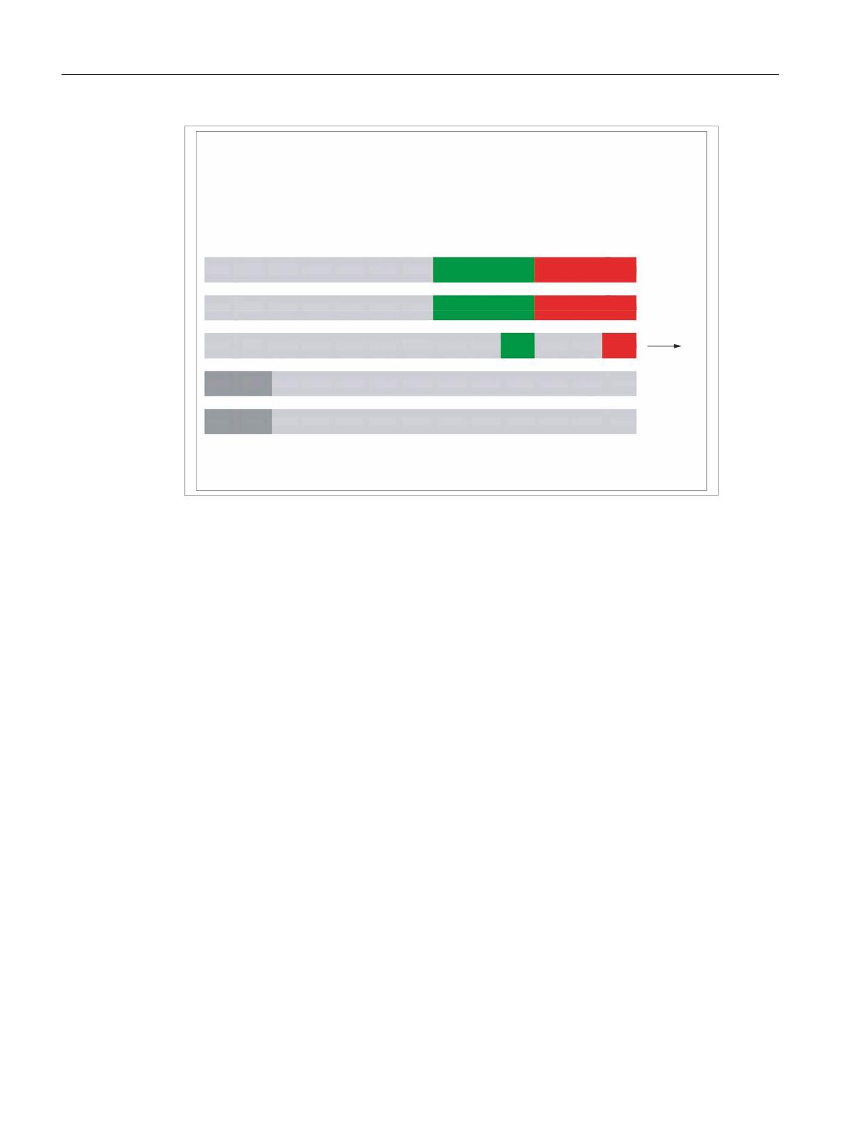
Image 9-35 MPP 483 Machine Push Button Panel
The figure shows the MPP 483 in the standard version.
The same slide-in labels can be used for the MPP 483H and the MPP 483A.
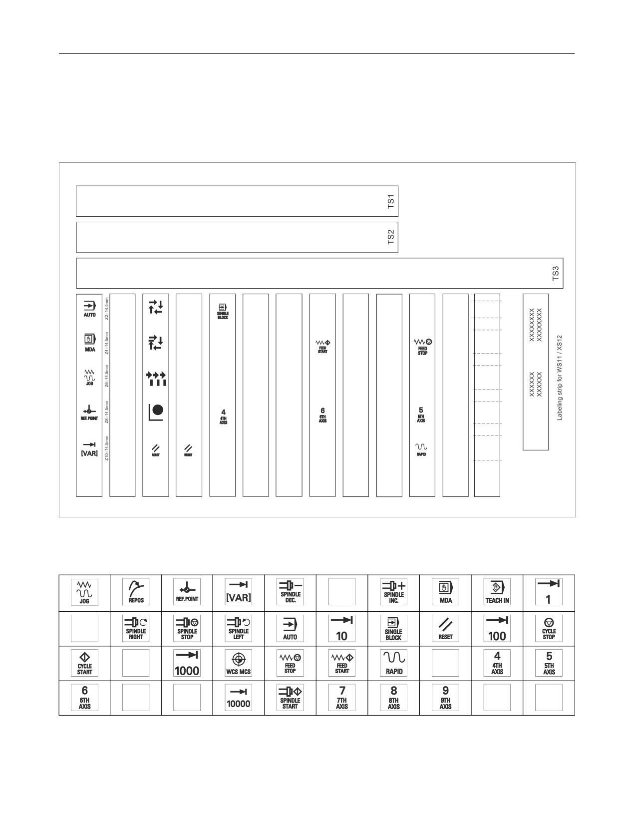
You can create your own slide-in labels in order to change the key labels. A printable blank
film (DIN A4) is supplied with the panel for this purpose.
A spare parts kit containing three blank films is also available (Item no.: A5E00414151).
Machine control panels
Manual, 03/2016, 6FC5397-1AP40-5BA3
319
Machine pushbutton panel: MPP 483
9.10 Accessories and spare parts
Image 9-36 Blank film for MCP 483 film keyboard
1) Print direction
Machine control panels
320
Manual, 03/2016, 6FC5397-1AP40-5BA3
Machine pushbutton panel: MPP 483
9.10 Accessories and spare parts
Files for printing the blank film
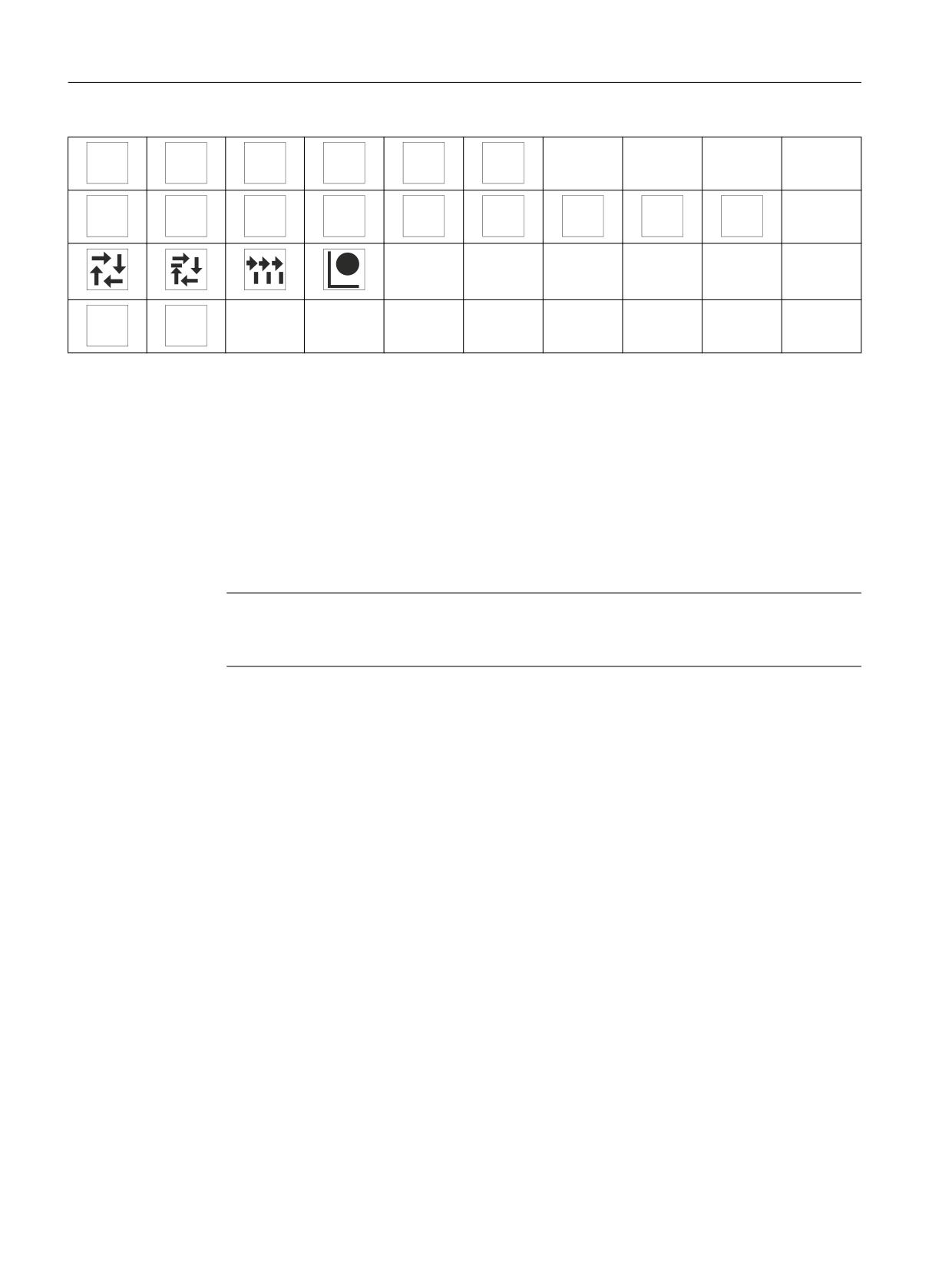
The DOConCD / Catalog NC 61 (CD enclosed) contains two files for printing the blank films:
● Template_MPP483.doc [assignment for standard variants of MPP 483 - (A)]
● SymbolsMPP483.doc [key symbols as Word file - (B)]
/DEHOLQJ VWULS IRU 033
033
$
033
+
7H[W
7H[W
7H[W
7H[W
7H[W
/DEHOLQJ VWULS RI WKH NH\ URZV WKH ULJKW WH[W ILHOG
LV RQO\ XVHG IRU WKH 033
/ DQG FDQ EH FXW WR
WKH QHFHVVDU\ OHQJWK
7H[W
7H[W
7H[W
7H[W
7H[W
/DEHOLQJ VWULS IRU 033
/
7H[W
7H[W
7H[W
7H[W
7H[W
7H[W
7H[W
7H[W
=
PP
WUDQVSDUHQW
/LQNHG
/LQNHG
1&
1&
PRGH
PRGH
6WDUW
6WRS
=
PP
WUDQVSDUHQW
6LQJOH
1H[W
6LQJOH
PRGH
$[HV
PRGH
=
PP
WUDQVSDUHQW
(6
;
(6
=
<
=
PP
WUDQVSDUHQW
(5
(5
=
PP
WUDQVSDUHQW
=
PP
WUDQVSDUHQW
)6
)6
)6
)6
)6
)6
)6
)6
)6
)6
)6
)6
)6
Image 9-37 Template_MPP483.doc (A)
Table 9-36
Symbole_MPP483.doc (B)
;
<
=
;
;
Machine control panels
Manual, 03/2016, 6FC5397-1AP40-5BA3
321
Machine pushbutton panel: MPP 483
9.10 Accessories and spare parts
<
<
=
=
&
&
1H[W
9.
(%
(6
(5
,2
60
66
68
$[HV
1&
1&
6WDUW
6WRS
Preparing standard slide-in labels with the aid of the file: "Template_MPP483.doc" (A)
1. Open the file "Template_MPP483.doc" in MS Word.
The key symbols are arranged in a table on the position that corresponds to their location
on the keyboard. The borders visible in the table are not printed.
2. Place the blank film in the printing direction in the slot of your laser printer (see figure: "Blank
film for MPP 483 membrane keyboard").
3. Select "film" as the printable medium if your printer allows this setting.
4. Start the printing process using MS Word.
Note
Make a test print on paper before you print on the film.
Allow the film to cool after printing so that the ink can dry.
5. Cut the slide-in labels out of the film along the edges (outer lines).
6. Round off the corners of the slide-in labels approx. 1.5 mm to facilitate insertion.
7. Slide in the printed slide-in label.
8. Shorten the labeling strip for the long-stroke keys for MPP 483 and MPP 483A, because
only the first four text fields of the strips TS1 and TS2 are needed.
Preparing specific slide-in labels with the aid of the file: "Symbole_MPP483.doc" (B)
1. Open both the "Symbole_MPP483.doc" file and the"Template_MPP483.doc" file.
2. Copy the desired key symbol from the file "Symbole_MPP483.doc".
3. Position the cursor in the desired field of the template (A), add the symbol and adjust its
size accordingly by dragging it by the gripping points.
Machine control panels
322
Manual, 03/2016, 6FC5397-1AP40-5BA3
Machine pushbutton panel: MPP 483
9.10 Accessories and spare parts
4. To move a symbol to a different position,
- select the symbol,
- cut it out and
- add it into the desired table cell.
5. If all the symbols are positioned as desired, follow the instructions in Section: "Preparing
standard slide-in labels with the aid of the file: "Template_MPP483.doc" as of point 2.
Note
Input of characters/text instead of symbols
Use the "Arial" font to format text. This font is comparable to the "Univers S57" font, used
by Siemens for the key labeling.
Creating your own symbols
● Drawing in a vector program (e.g. Designer, Freehand, CorelDraw):
- Draw a square 15 x 15 mm without frames, filled with the color white.
- Place the graphic in the center of this square.
- Group the graphic and square together and add this group to the file
"Template_MPP483.doc".
● Drawing in an image editing program (e.g. Photoshop, Picture Publisher, Paint)
- Create a square area (e.g. 100 x 100 pixels) filled with the color white.
- Draw the graphic or add an image in the center of this square.
- Copy the graphic and square and add them both to the file "Template_MPP483.doc".
Machine control panels
Manual, 03/2016, 6FC5397-1AP40-5BA3
323
Machine pushbutton panel: MPP 483
9.10 Accessories and spare parts
9.10.3
Handwheel connection
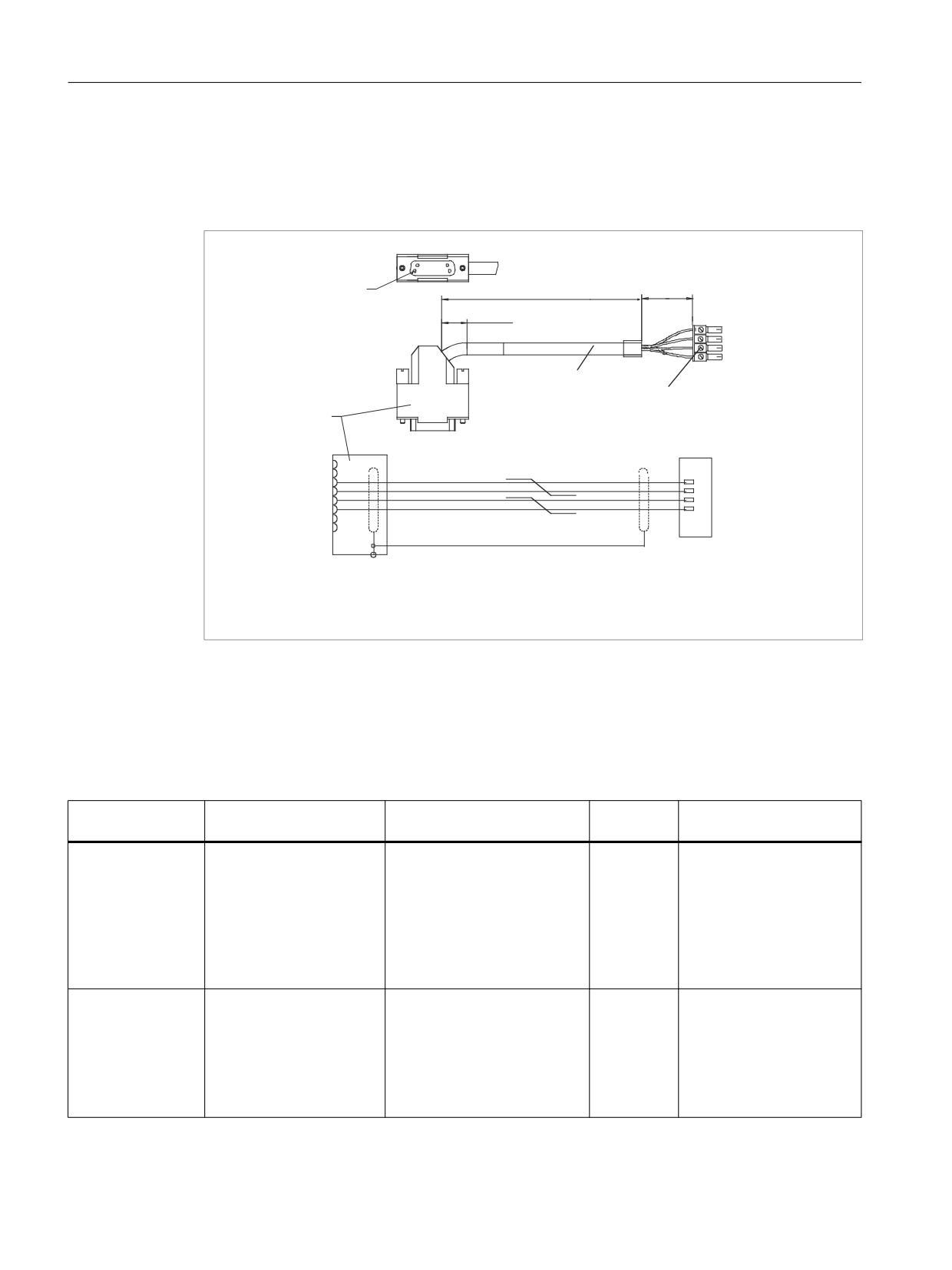
A connecting cable is available to connect the COM board handwheels, see Accessories and
spare parts (Page 27).
'LPHQVLRQV LQ PP
3LQ
1
$B+:
;$B+:
%B+:
;%B+:
6KLHOG
+RXVLQJ
([SODQDWLRQ
6LJQDO FRQQHFWRU
6LJQDO FDEOH
6LJQDO FRQQHFWRU 0&
67
3+2(1,;
Image 9-38 Connection cable for HHU handwheel
9.10.4
Display elements and operator controls
You can retrofit the following control elements:
Function
Upper section
Lower section
Mounting
Application
actuator / accessories
contact block / signaling lamp
location
Signaling light
Illuminated nipple 28 mm
AL5 lamp socket with spot LED
S1 ... S4
Light
∅
S7 ... S10
RXJN-GB (yellow)
RXJN-GN (green)
RXJN-RT (red)
RXJN-BL (blue)
RXJN-KL (crystal clear)
RXJN-WS (white)
Button
Pushbutton 28 mm ∅
Button contact maker AT2
S1 ... S4
For S1, 1 NC internal,
RXJN-GB (yellow)
S7 ... S10
2 NO + 1 NC external
RXJN-GN (green)
For S2 ... S4, S7 ... S10,
RXJN-RT (red)
1 NC internal, 1 NO + 1 NC
RXJN-BL (blue)
external
RXJN-KL (crystal clear)
RXJN-GWS (black)
Machine control panels
324
Manual, 03/2016, 6FC5397-1AP40-5BA3
Machine pushbutton panel: MPP 483
9.10 Accessories and spare parts
Function
Upper section
Lower section
Mounting
Application
actuator / accessories
contact block / signaling lamp
location
Illuminated key
Pushbutton 28 mm ∅
Illuminated button contact
S1 ... S4
For S1, 1 NC internal,
with socket for
RXJN-GB (yellow)
maker ATL2 with spot LED
S7 ... S10
2 NO + 1 NC external
T5.5K
RXJN-GN (green)
For S2 ... S4, S7 ... S10,
RXJN-RT (red)
1 NC internal, 1 NO + 1 NC
RXJN-BL (blue)
external
RXJN-KL (crystal clear)
Spot LED
L5.5K28UW (white)
S1 ... S4
S7 ... S10
Keyswitch *)
Safety lock cylinder 28
Button contact maker AT2
S1 ... S4
For S1, 1 NC internal,
switching angle of
mm ∅
S7 ... S10
2 NO + 1 NC external
90°, 2 positions
RXJSSA 15 E
For S2 ... S4, S7 ... S10,
key can be removed when
1 NC internal, 1 NO + 1 NC
in both positions
external
Keys / position se-
RX-JEWEL 22.3 mm
Button contact maker AT2
S1 ... S4
lector
Schlegel catalog
S7 ... S10
Raised keys
2 RTAO pushbuttons with
2 AT2 special version
S1 ... S4
6FC5247-0AA41-0
plunger elongation
S7 ... S10
AA0
*) Safety-related
Note
When assigning the colors for keys and signaling lights to the corresponding functionality,
observe the standard EN 60204 Part 1 or VDE 113 Part 1, Chapter Pushbuttons/colors.
Name
Description
Num-
Article number
Mounting location
ber
Dummy plug
BVR22
1
S1 ... S4
S7 ... S10
Selector switch
Toggle FS1
1
WS1
Conversion to toggle switch
Override spindle / rapid
Electronic rotary switch 1x16G,
1
6FC5247-0AF12-1AA0
WS3
traverse
T=24, cap, button, pointer, spin-
dle dials and rapid traverse
Override feed / rapid
Electronic rotary switch 1x23G,
1
6FC5247-0AF13-1AA0
WS2
traverse
T=32, cap, button, pointer, feed
dials and rapid traverse
Override feed / rapid
Electronic rotary switch 1x29G,
1
6FC5247-0AF14-1AA0
WS5
traverse1)
T=32, cap, button, pointer, feed
dials and rapid traverse
Machine control panels
Manual, 03/2016, 6FC5397-1AP40-5BA3
325

Machine pushbutton panel: MPP 483
9.10 Accessories and spare parts
Name
Description
Num-
Article number
Mounting location
ber
22 mm actuating element, 40 mm
1
3SB3000-1HA20 *)
S13
mushroom pushbutton, snap ac-
tion with tamper protection, latch-
ing, red, with holder, unlit
EMERGENCY STOP
Contact block, 2 NC,
1
3SB3400-0E *)
S13
Extension NC, emergency stop
Protective collar for front panel
1
3SB3921-0AK
S13
mounting,
protection against accidental ac-
tuation
Control and signaling
All elements marked with LE
3SB3 following selection from
S51 ... S62
devices
Low-Voltage Controls and Dis-
S14, S15
tribution Catalog (LV 1)
EKS
Serial interface
EKS-A-ISX-G01-ST09/03
S14
Euchner identification
EKS-A-IDX-G01-ST09/03
system
PROFIBUS DP interface
1) only for option
*) Safety-related
Machine control panels
326
Manual, 03/2016, 6FC5397-1AP40-5BA3
MCP Interface PN
10
10.1
Description
The MCP Interface PN module enables customer-specific machine control panels to be
connected to a machine tool. Communication is handled via PROFINET RT or Industrial
Ethernet.
You can connect the following operator controls to the interface:
●
80 single keys
●
64 LEDs
●
2 handwheels
●
2 rotary override switches
The following inputs/outputs are also available:
●
9 digital inputs (5 V)
●
6 digital inputs (24 V)
●
15 digital inputs (24 V / each 0.15 A)
Validity
The following description applies to the MCP PN interface.
Article number: 6FC5303-0AF03-0AA0
System configuration
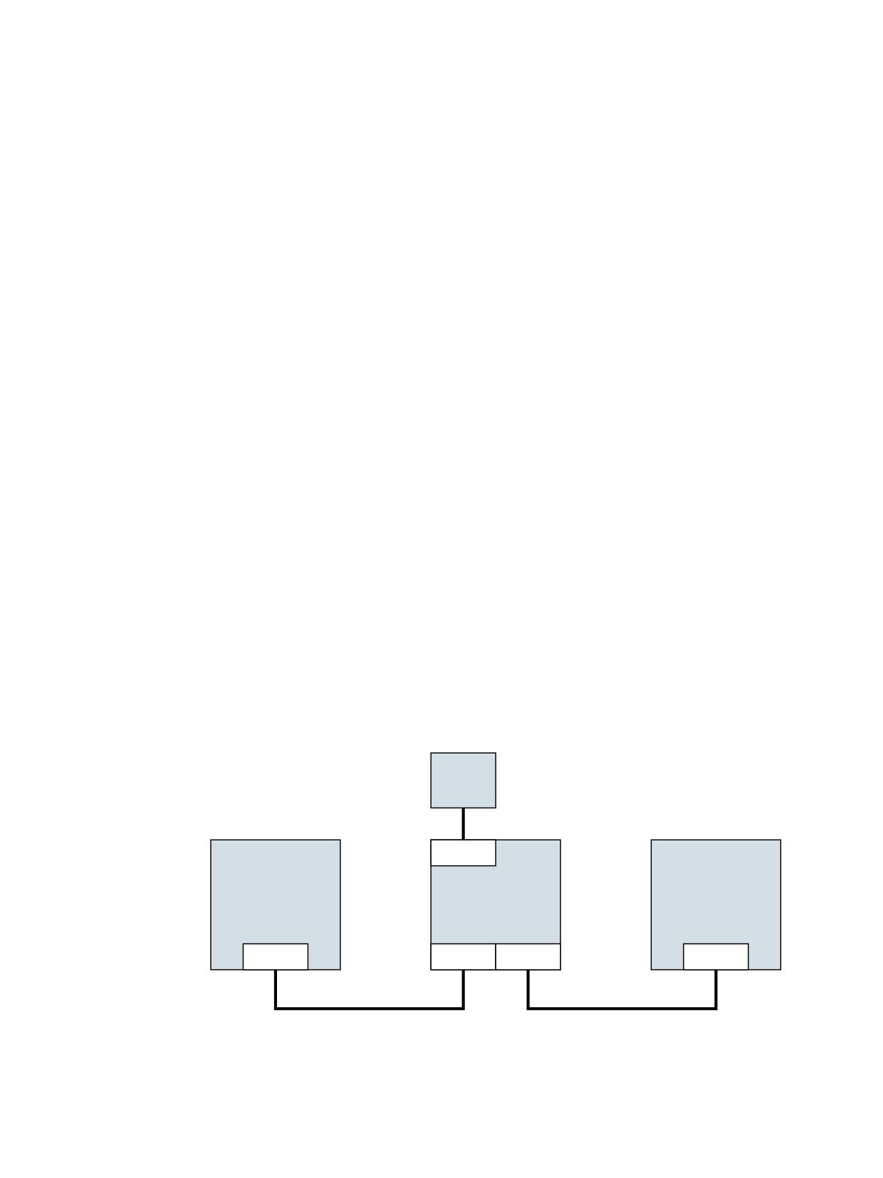
The following diagram shows a system configuration with ETHERNET.
b9 '& SRZHU VXSSO\
;
2SHUDWRU SDQHO
1&8
0&3 ,QWHUIDFH 31
ZLWK
H J 7&8 [
;
;
;
;
(7+(51(7
(7+(51(7
Alternatively, you can connect the MCP Interface PN module via PROFINET to the NCU. The
TCU must remain connected to the NCU via ETHERNET.
Machine control panels
Manual, 03/2016, 6FC5397-1AP40-5BA3
327
MCP Interface PN
10.1 Description
9 '& SRZHU VXSSO\
;
2SHUDWRU SDQHO
1&8
0&3 ,QWHUIDFH 31
ZLWK
H J 7&8 [
;
;
;
;
(7+(51(7
352),1(7
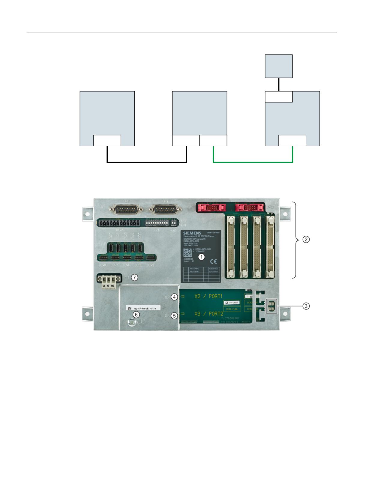
Diagram
① Rating plate
② Terminal strips / connectors for operator controls
③ Diagnostic LEDs
④ PROFINET interface X2 (Industrial Ethernet 10/100 Mbit/s)
⑤ PROFINET interface X3 (Industrial Ethernet 10/100 Mbit/s)
⑥ Grounding screw M5 for potential equalization connection
⑦ 24 VDC power supply X1
Image 10-1 View of MCP Interface PN
Machine control panels
328
Manual, 03/2016, 6FC5397-1AP40-5BA3
MCP Interface PN
10.1 Description
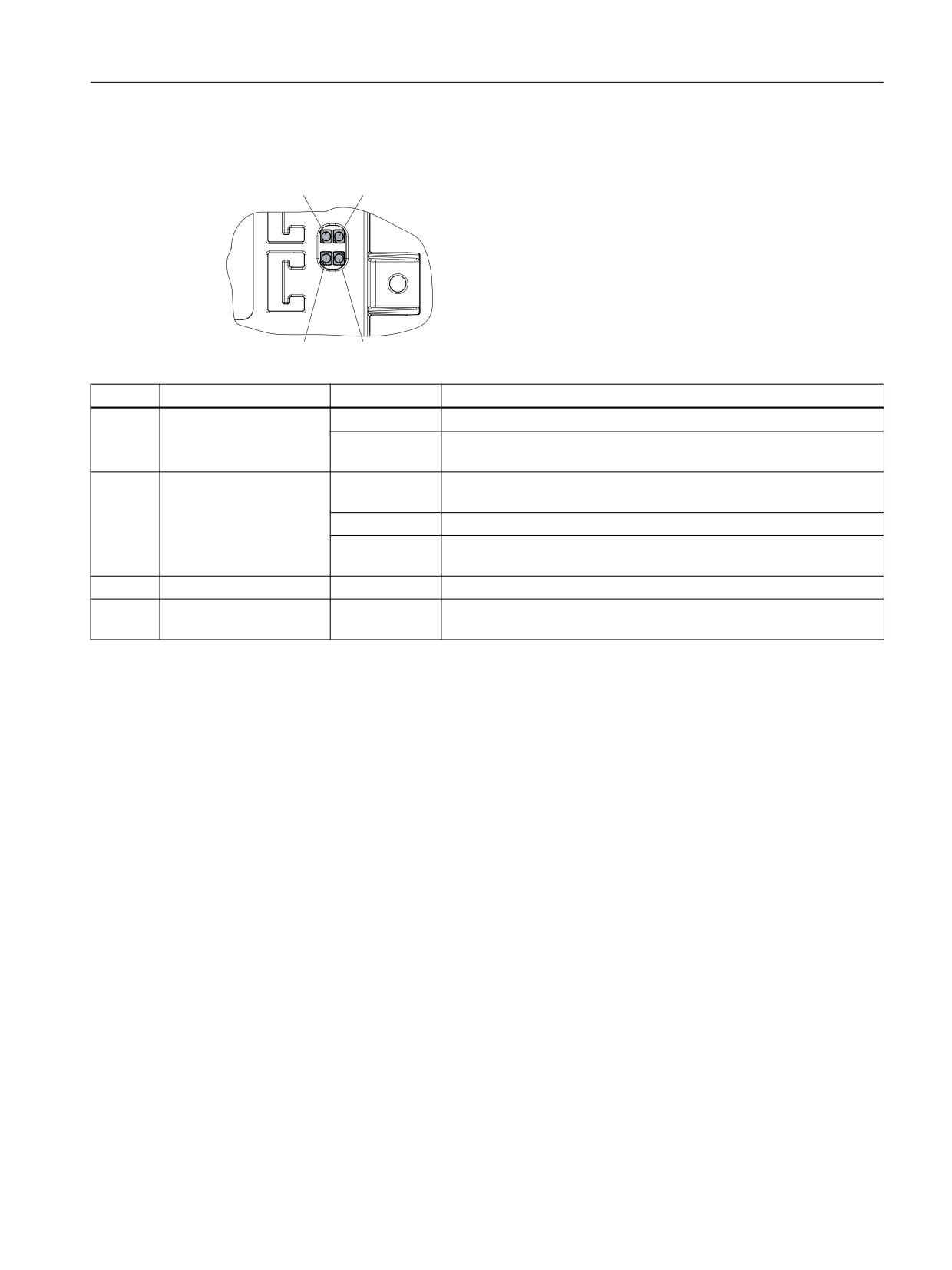
LED displays
+
+
+
+
Name
Function
State
Meaning
H500
POWER OK (green)
Lights up
All internal voltages are in the setpoint range.
Does not light
At least one of the generated voltages has exceeded its setpoint; a
up
reset will be initiated.
H501
BUS_SYNC
Does not light
No PROFINET communication.
up
Lights up
PROFINET is synchronized (STOP state).
Flashes (0.5
PROFINET is synchronized (RUN state).
Hz)
H502
BUS_FAULT
Lights up
PROFINET group fault.
H505
Temperature alarm (red)
Lights up
The upper limit temperature (T_Critical) of temperature sensor LM77
has been exceeded.
Machine control panels
Manual, 03/2016, 6FC5397-1AP40-5BA3
329
MCP Interface PN
10.2 Interfaces
10.2
Interfaces
10.2.1
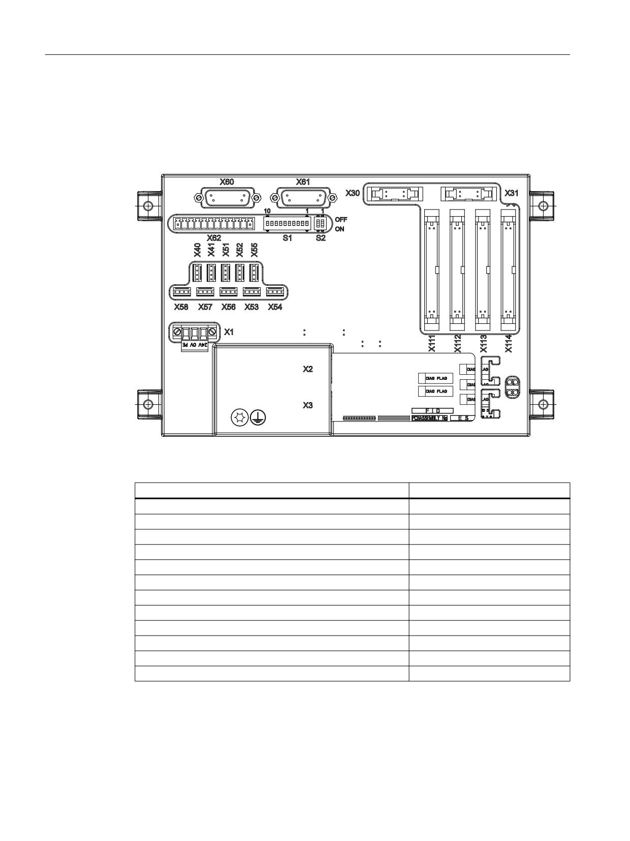
Overview
1
12
Image 10-2 MCP Interface PN interfaces
Function
Designation
24 VDC power supply
X1
PROFINET interface
X2
PROFINET interface
X3
Feed rotary override switch
X30
Spindle override rotary switch
X31
Digital inputs (24 V)
X40, X41
Digital inputs (TTL)
X51, X52, X55
Digital outputs (24 V)
X53, X54, X56, X57, X58
Handwheels
X60, X61, X62
Keys and LED interface
X111, X112, X113, X114
DIP switch for setting the MCP address
S1
DIP switch for setting the handwheel signal type
S2
Machine control panels
330
Manual, 03/2016, 6FC5397-1AP40-5BA3
MCP Interface PN
10.2 Interfaces
10.2.2
Terminals
Pin assignment
In principle you will find the pin assignments of the individual interfaces in "General information
and networking", Section "Connecting", except for: The interfaces for digital inputs/outputs and
the handwheel terminal strip X62.
Digital inputs X40, X41
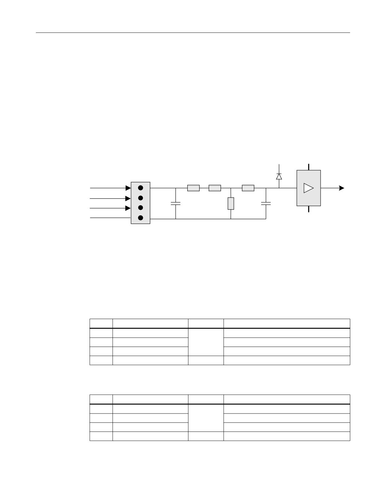
A total of six 24 V signals can be evaluated via the X40 and X41 connectors.
9
9
;
N
N
N
,1B
9> @
,1B
9> @
,1B
9> @
Q
N
Q
0
0
0
Image 10-3 Schematic circuit diagram for X40
Connector designation:
X40, X41
Connector type:
4-pin plug connector
Special features:
No galvanic isolation, short-circuit proof
Max. cable length:
0.6 m
Table 10-1
Assignment of connector X40
Pin
Name
Type
Meaning
1
IN_24V[0]
24 V input 0
2
IN_24V[1]
I
24 V input 1
3
IN_24V[2]
24 V input 2
4
M
V
Ground
Table 10-2
Assignment of connector X41
Pin
Name
Type
Meaning
1
IN_24V[3]
24 V input 3
2
IN_24V[4]
I
24 V input 4
3
IN_24V[5]
24 V input 5
4
M
V
Ground
Machine control panels
Manual, 03/2016, 6FC5397-1AP40-5BA3
331
MCP Interface PN
10.2 Interfaces
Table 10-3
Technical data for X40 and X41
Parameters
Value
Voltage:
-3 V to 30 V
Typical current consumption:
6 mA at 24 VDC
Signal level (including ripple):
High signal level: 15 V to 30 V
Low_Level: -3 V to 5 V
Digital inputs X51, X52, X55
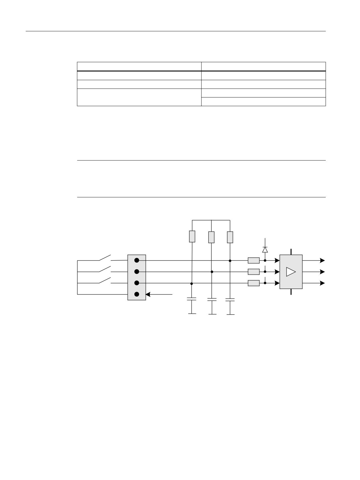
Only switches (passive inputs) may be connected via the X51, X52 and X55 connectors.
Typically, illuminated pushbuttons are connected here. The lamps in the pushbuttons are
activated via X53, X54, X56, X57 and X58.
Note
Connection miniature handheld unit
Alternatively, at the inputs X51, X52 and X55, one miniature handheld unit may be operated.
For details, please refer to the corresponding section.
9
9
N
9
;
N
,1 > @
,1 > @
,1 > @
0
0
Q)
0
0
0
Image 10-4 Schematic circuit diagram for X51
Connector designation:
X51, X52, X55
Connector type:
4-pin plug connector
Special feature:
No galvanic isolation
Max. cable length:
0.6 m
Machine control panels
332
Manual, 03/2016, 6FC5397-1AP40-5BA3
MCP Interface PN
10.2 Interfaces
Table 10-4
Assignment of connector X51
Pin
Name
Type
Meaning
1
IN6[0]
Customer key 0
2
IN6[1]
I
Customer key 1
3
IN6[2]
Customer key 2
4
M
V
Ground
Table 10-5
Assignment of connector X52
Pin
Name
Type
Meaning
1
IN6[3]
Customer key 3
2
IN6[4]
I
Customer key 4
3
IN6[5]
Customer key 5
4
M
V
Ground
Table 10-6
Assignment of connector X55
Pin
Name
Type
Meaning
1
IN6[6]
Customer key 6
2
IN6[7]
I
Customer key 7
3
IN6[8]
Customer key 8
4
M
V
Ground
Table 10-7
Technical data for X51, X52 and X55
Parameters
Value
Voltage:
Nominal: 0 V to 5 V
Permissible: -3 V to 30 V
Typical current consumption:
0.2 mA at 5 VDC
-0.3 mA at 0 VDC
Signal level (including ripple):
High signal level: 2.3 V to 5 V
Low signal level: 0 V to 1 V
Machine control panels
Manual, 03/2016, 6FC5397-1AP40-5BA3
333
MCP Interface PN
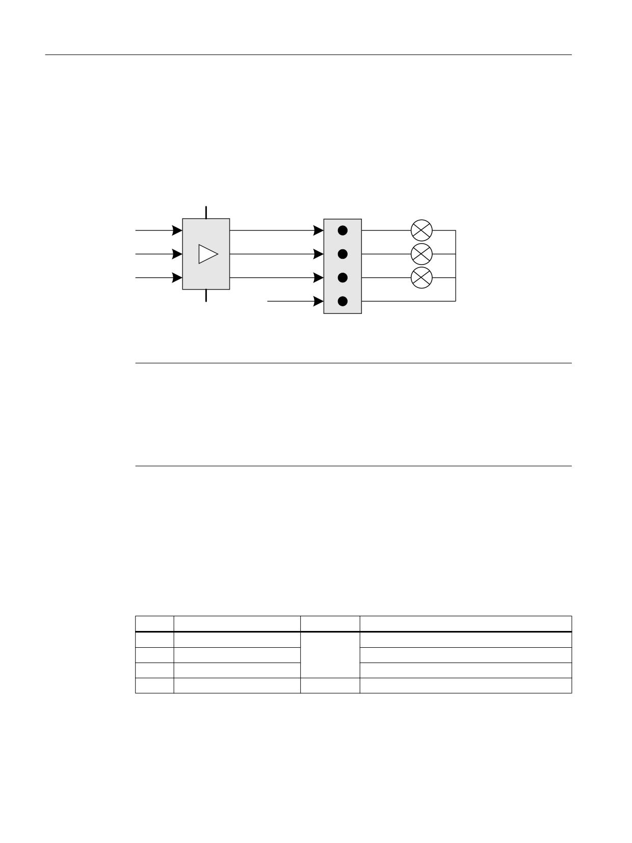
10.2 Interfaces
Digital outputs X53, X54, X56, X57, X58
The fifteen outputs are provided to control lamps in the illuminated pushbuttons.
Recommended are lamps with 1.2 W (50 mA). Only "small" relays, valves, etc. can be
connected.
+LJK 6LGH
6ZLWFK
3
;
287B
9> @
287B
9> @
287B
9> @
0
0
Image 10-5 Schematic circuit diagram for X54
Note
Observe the utilization of the power supply
The fifteen 24 V outputs are divided into two groups with eight or seven outputs.
● Group 1 covers the output signals OUT_24V[0 ... 7]
● Group 2 covers the output signals OUT_24V[8 ... 14]
Each group may load the 24 V power supply with max. 1.2 A.
Connector designation:
X53, X54, X56, X57, X58
Connector type:
4-pin plug connector
Special features:
No galvanic isolation, short-circuit proof
Max. cable length:
0.6 m
Table 10-8
Assignment of connector X54
Pin
Name
Type
Meaning
1
OUT_24V[0]
24 V output 0 (group 1)
2
OUT_24V[1]
O
24 V output 1 (group 1)
3
OUT_24V[2]
24 V output 2 (group 1)
4
M
V
Ground
Machine control panels
334
Manual, 03/2016, 6FC5397-1AP40-5BA3
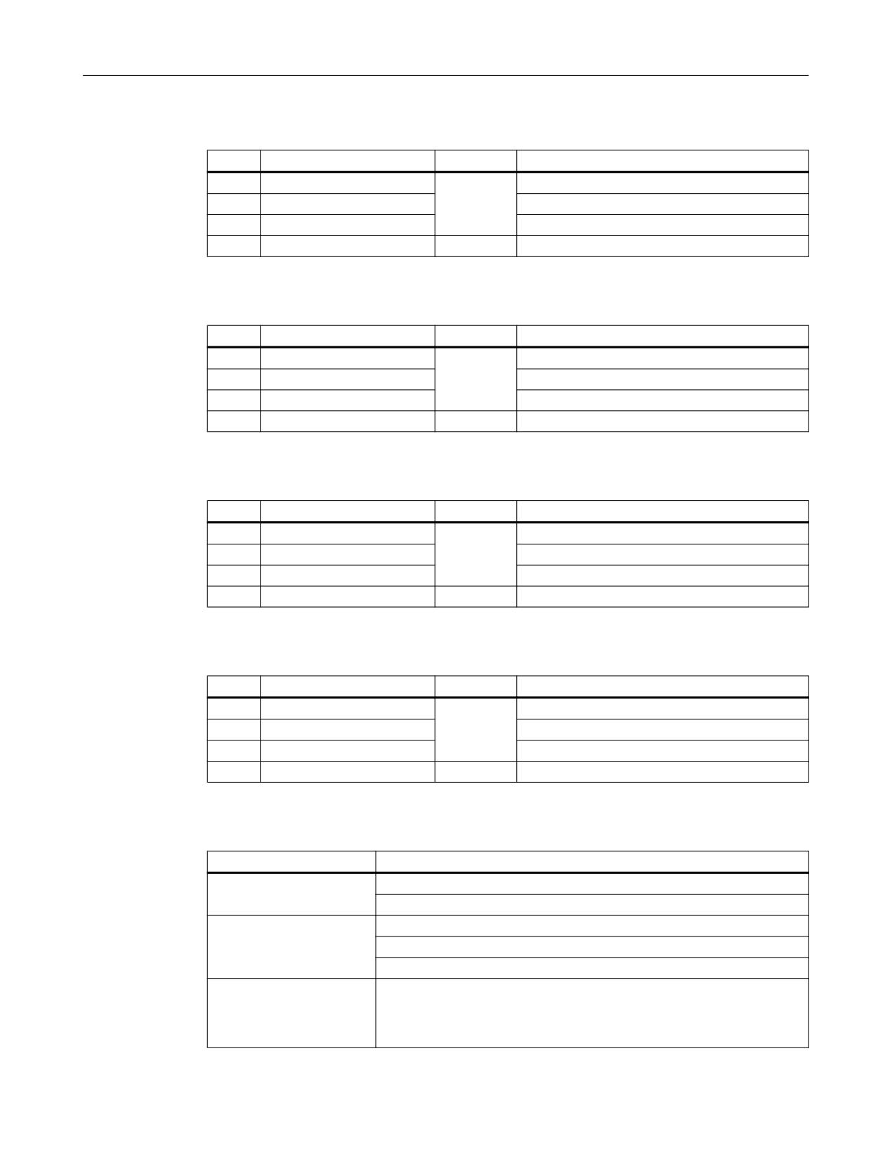
MCP Interface PN
10.2 Interfaces
Table 10-9
Assignment of connector X53
Pin
Name
Type
Meaning
1
OUT_24V[3]
24 V output 3 (group 1)
2
OUT_24V[4]
O
24 V output 4 (group 1)
3
OUT_24V[5]
24 V output 5 (group 1)
4
M
V
Ground
Table 10-10 Assignment of connector X56
Pin
Name
Type
Meaning
1
OUT_24V[6]
24 V output 6 (group 1)
2
OUT_24V[7]
O
24 V output 7 (group 1)
3
OUT_24V[8]
24 V output 8 (group 2)
4
M
V
Ground
Table 10-11 Assignment of connector X57
Pin
Name
Type
Meaning
1
OUT_24V[9]
24 V output 9 (group 2)
2
OUT_24V[10]
O
24 V output 10 (group 2)
3
OUT_24V11]
24 V output 11 (group 2)
4
M
V
Ground
Table 10-12 Assignment of connector X58
Pin
Name
Type
Meaning
1
OUT_24V[12]
24 V output 12 (group 2)
2
OUT_24V[13]
O
24 V output 13 (group 2)
3
OUT_24V[14]
24 V output 14 (group 2)
4
M
V
Ground
Table 10-13 Technical data for X53, X54, X56, X57 and X58
Parameters
Value
Voltage:
Nominal: 24 V
Permissible: 18 V to 30 V
Max. load current:
Per output: 0.7 A
Per connector: 1 A
Per output at 100% simultaneity of all fifteen outputs: 0.15 A
UL certified rating
Each output:
24 V / 0.15 A general, resistive
24 V / 3.6 W tungsten
24 V / 0.15 A pilot duty
Machine control panels
Manual, 03/2016, 6FC5397-1AP40-5BA3
335

MCP Interface PN
10.2 Interfaces
X62 handwheels
Up to two handwheels can be connected via the X62. This means, purely on the basis of
calculations, together with X60 and X61, four handwheels can be inserted. However, only a
total of two handwheels can be operated concurrently because the signals from X60 and X61
are routed parallel to X62.
Switching between TTL and differential signals: See switch S2.
Note
The handwheels are supplied by the MCP Interface PN module with 5 V / 100 mA. An external
power supply is not permitted.
Connector designation:
X62
Connector type:
12-pin plug connector
Special features:
No galvanic isolation
Max. cable length:
5 m
Table 10-14 Assignment of connector X62
Pin
Name
Type
Meaning
1
P5HW
V
5 V power supply
2
M
V
Ground
3
HW1_A
I
Handwheel 1 pulses track A
4
HW1_XA
I
Handwheel 1 pulses track A (negated)
5
HW1_B
I
Handwheel 1 pulses track B
6
HW1_XB
I
Handwheel 1 pulses track B (negated)
7
P5HW
V
5 V power supply
8
M
V
Ground
9
HW2_A
I
Handwheel 2 pulses track A
10
HW2_XA
I
Handwheel 2 pulses track A (negated)
11
HW2_B
I
Handwheel 2 pulses track B
12
HW2_XB
I
Handwheel 2 pulses track B (negated)
Machine control panels
336
Manual, 03/2016, 6FC5397-1AP40-5BA3
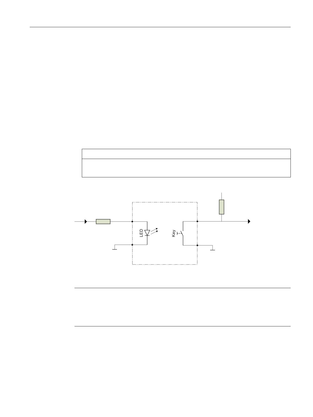
MCP Interface PN
10.2 Interfaces
Digital inputs and outputs X111, X112, X113, X114
You can connect up to 80 keys and 64 LEDs. The connectors are connected to the machine
control panel with ribbon cables.
● Inputs:
All keys signal "high" in the idle state (= open). When actuated, the state changes to "low".
Short-stroke keyboards and membrane keyboards can be connected. 5 V signals can also
be applied to the inputs. They are TTL-compatible, but not 24 V-tolerant.
● Outputs:
- Instead of a LED, an external logic with TTL-compatible inputs can also be connected.
Because the P5 (=5 V) routed externally are not short-circuit proof, they may be loaded
in total (X111 to X114) with maximum 500 mA.
- Because of the series resistor, the outputs are short-circuit proof but not protected
against external overvoltage.
NOTICE
The provision of an external voltage can destroy the module.
No voltage may be supplied at the P5 connections.
3 9
N˖
5Y
;
;
,1 > @
˖
;
;
0
0
0DFKLQH FRQWURO SDQHO
Image 10-6 X111 schematic circuit diagram
Note
LED brightness
The setting of the LED brightness can be implemented by an additional external resistor
connected in series. Alternatively, the LEDs can also be operated with polarity reversal at P5,
in which case the LEDs illuminate for low signal level.
Connector designation:
X111, X112, X113, X114
Connector type:
40-pin plug connector
Special features:
No galvanic isolation, with interlock
Max. cable length:
2 m
Machine control panels
Manual, 03/2016, 6FC5397-1AP40-5BA3
337

MCP Interface PN
10.2 Interfaces
Note
Allocation of the inputs/outputs
● The inputs INi[j] are allocated into five groups (i=0..4) each of 16 inputs (j=0..15).
● The outputs OUTi[j] are allocated into four groups (i=0..3) each of 16 inputs (j=0..15).
Example: IN0[0] = input 0 of group 0
Table 10-15 Assignment of connector X111
Pin
Name
Type
Pin
Name
Type
1
Ground
V
2
Ground
V
3
IN0[0]
I
4
OUT0[0]
O
5
IN0[1]
6
OUT0[1]
7
IN0[2]
8
OUT0[2]
9
IN0[3]
10
OUT0[3]
11
IN0[4]
12
OUT0[4]
13
IN0[5]
14
OUT0[5]
15
IN0[6]
16
OUT0[6]
17
IN0[7]
18
OUT0[7]
19
IN0[8]
20
OUT0[8]
21
IN0[9]
22
OUT0[9]
23
IN0[10]
24
OUT0[10]
25
IN0[11]
26
OUT0[11]
27
IN0[12]
28
OUT0[12]
29
IN0[13]
30
OUT0[13]
31
IN0[14]
32
OUT0[14]
33
IN0[15]
34
OUT0[15]
35
IN4[0]
36
IN4[1]
I
37
IN4[2]
38
IN4[3]
I
39
P5 = 5 V
V
40
P5 = 5 V
V
Machine control panels
338
Manual, 03/2016, 6FC5397-1AP40-5BA3

MCP Interface PN
10.2 Interfaces
Table 10-16 Assignment of connector X112
Pin
Name
Type
Pin
Name
Type
1
Ground
V
2
Ground
V
3
IN1[0]
I
4
OUT1[0]
O
5
IN1[1]
6
OUT1[1]
7
IN1[2]
8
OUT1[2]
9
IN1[3]
10
OUT1[3]
11
IN1[4]
12
OUT1[4]
13
IN1[5]
14
OUT1[5]
15
IN1[6]
16
OUT1[6]
17
IN1[7]
18
OUT1[7]
19
IN1[8]
20
OUT1[8]
21
IN1[9]
22
OUT1[9]
23
IN1[10]
24
OUT1[10]
25
IN1[11]
26
OUT1[11]
27
IN1[12]
28
OUT1[12]
29
IN1[13]
30
OUT1[13]
31
IN1[14]
32
OUT1[14]
33
IN1[15]
34
OUT1[15]
35
IN4[4]
36
IN4[5]
I
37
IN4[6]
38
IN4[7]
I
39
P5 = 5 V
V
40
P5 = 5 V
V
Machine control panels
Manual, 03/2016, 6FC5397-1AP40-5BA3
339
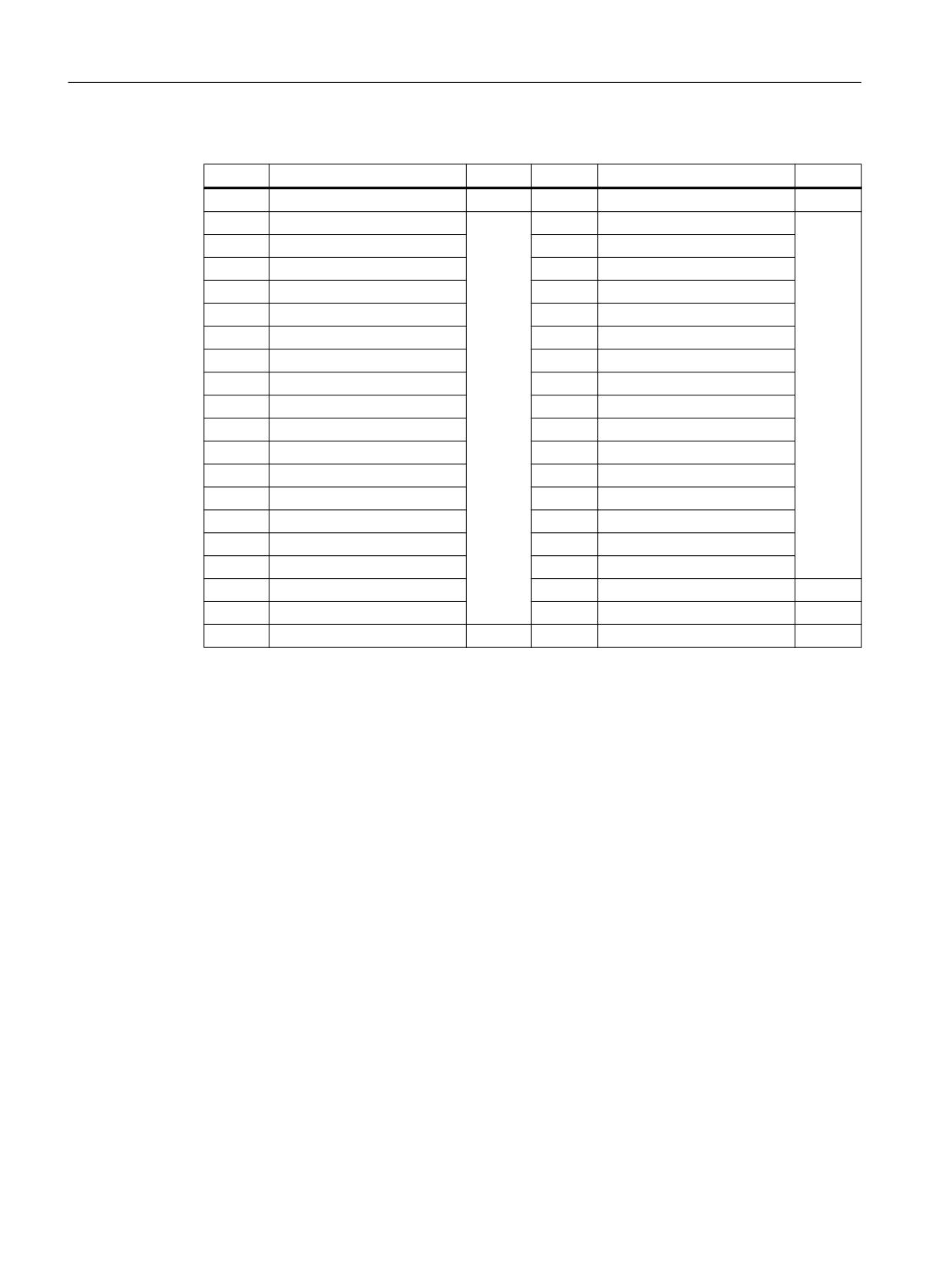
MCP Interface PN
10.2 Interfaces
Table 10-17 Assignment of connector X113
Pin
Name
Type
Pin
Name
Type
1
Ground
V
2
Ground
V
3
IN2[0]
I
4
OUT2[0]
O
5
IN2[1]
6
OUT2[1]
7
IN2[2]
8
OUT2[2]
9
IN2[3]
10
OUT2[3]
11
IN2[4]
12
OUT2[4]
13
IN2[5]
14
OUT2[5]
15
IN2[6]
16
OUT2[6]
17
IN2[7]
18
OUT2[7]
19
IN2[8]
20
OUT2[8]
21
IN2[9]
22
OUT2[9]
23
IN2[10]
24
OUT2[10]
25
IN2[11]
26
OUT2[11]
27
IN2[12]
28
OUT2[12]
29
IN2[13]
30
OUT2[13]
31
IN2[14]
32
OUT2[14]
33
IN2[15]
34
OUT2[15]
35
IN4[8]
36
IN4[9]
I
37
IN4[10]
38
IN4[11]
I
39
P5 = 5 V
V
40
P5 = 5 V
V
Machine control panels
340
Manual, 03/2016, 6FC5397-1AP40-5BA3
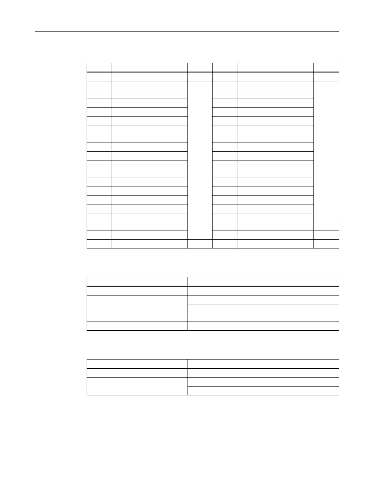
MCP Interface PN
10.2 Interfaces
Table 10-18 Assignment of connector X114
Pin
Name
Type
Pin
Name
Type
1
Ground
V
2
Ground
V
3
IN3[0]
I
4
OUT3[0]
O
5
IN3[1]
6
OUT3[1]
7
IN3[2]
8
OUT3[2]
9
IN3[3]
10
OUT3[3]
11
IN3[4]
12
OUT3[4]
13
IN3[5]
14
OUT3[5]
15
IN3[6]
16
OUT3[6]
17
IN3[7]
18
OUT3[7]
19
IN3[8]
20
OUT3[8]
21
IN3[9]
22
OUT3[9]
23
IN3[10]
24
OUT3[10]
25
IN3[11]
26
OUT3[11]
27
IN3[12]
28
OUT3[12]
29
IN3[13]
30
OUT3[13]
31
IN3[14]
32
OUT3[14]
33
IN3[15]
34
OUT3[15]
35
IN4[12]
36
IN4[13]
I
37
IN4[14]
38
IN4[15]
I
39
P5 = 5 V
V
40
P5 = 5 V
V
Table 10-19 Technical data of the inputs of X111 to X114
Parameters
Value
Voltage:
0 V to 5 V
Typical current consumption:
0.2 mA at 5 VDC
-0.3 mA at 0 VDC
Signal level (including ripple):
High signal level: 2.3 V to 5 V
Low signal level: 0 V to 1 V
Table 10-20 Technical data of the outputs of X111 to X114
Parameters
Value
Voltage:
0 V to 5 V (depending on the load)
Typical load current (without external
8 mA at LED flow voltage = 2.3 V
series resistor):
15 mA at short-circuit
Machine control panels
Manual, 03/2016, 6FC5397-1AP40-5BA3
341
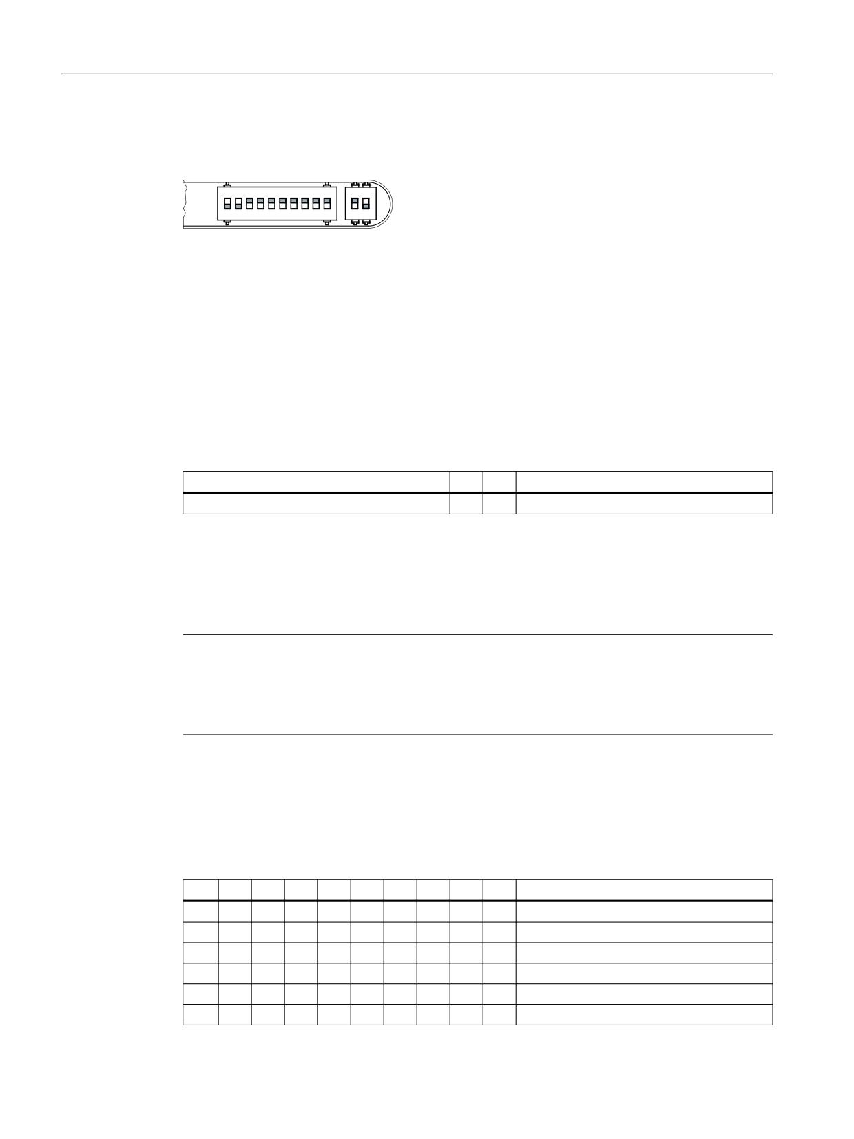
MCP Interface PN
10.2 Interfaces
10.2.3
Switch
2))
21
6
6
Image 10-7 DIP switches S1, S2 in the delivered condition
The switches have the following meaning in the delivered condition:
● S1 is in PROFINET mode with default device name "mcp-pn".
● S2 is in the "differential interface connection" handwheel signal type position.
Switch S1 in PROFINET mode
Table 10-21 General switch S1 setting
1-8
9
10
Meaning
off
on
on
PROFINET device name: mcp-pn
The two switches S1-9 and S1-10 must remain set to "on" in order for PN functionality to be
supported.
The switches S1-1 to S1-8 define the default device name. Up to 128 default device names
are permitted: If these default device names are used, there is no need for initialization of the
MCP.
Note
The default device names cannot be reconfigured using the STEP7 "device initialization" facility
for example.
If you are connecting the MCP Interface PN to a SINUMERIK control as a PROFINET
component, make sure that this functionality is supported by the control concerned.
DCP mode:
No default device name is available in this mode. The device name must be set by means of
an initialization procedure and remains saved on the interface. It is deleted again if the factory
setting is restored, e.g. using STEP7.
Table 10-22 Switch S1 settings in PROFINET mode
1
2
3
4
5
6
7
8
9
10
Meaning
on
on
on
on
on
on
on
on
on
on
DCP mode
on
on
on
on
on
on
on
off
Default device name: mcp-pn127
off
on
on
on
on
on
on
off
Default device name: mcp-pn126
on
off
on
on
on
on
on
off
Default device name: mcp-pn125
Machine control panels
342
Manual, 03/2016, 6FC5397-1AP40-5BA3

MCP Interface PN
10.2 Interfaces
1
2
3
4
5
6
7
8
9
10
Meaning
off
off
on
on
on
on
on
off
Default device name: mcp-pn124
on
on
off
on
on
on
on
off
Default device name: mcp-pn123
off
on
off
on
on
on
on
off
Default device name: mcp-pn122
on
off
off
on
on
on
on
off
Default device name: mcp-pn121
off
off
off
on
on
on
on
off
Default device name: mcp-pn120
on
on
on
off
on
on
on
off
Default device name: mcp-pn119
off
on
on
off
on
on
on
off
Default device name: mcp-pn118
on
off
on
off
on
on
on
off
Default device name: mcp-pn117
off
off
on
off
on
on
on
off
Default device name: mcp-pn116
on
on
off
off
on
on
on
off
Default device name: mcp-pn115
off
on
off
off
on
on
on
off
Default device name: mcp-pn114
on
off
off
off
on
on
on
off
Default device name: mcp-pn113
off
off
off
off
on
on
on
off
Default device name: mcp-pn112
x
x
x
x
x
x
x
x
"
on
on
on
on
off
off
off
off
Default device name: mcp-pn15
off
on
on
on
off
off
off
off
Default device name: mcp-pn14
on
off
on
on
off
off
off
off
Default device name: mcp-pn13
off
off
on
on
off
off
off
off
Default device name: mcp-pn12
on
on
off
on
off
off
off
off
Default device name: mcp-pn11
off
on
off
on
off
off
off
off
Default device name: mcp-pn10
on
off
off
on
off
off
off
off
Default device name: mcp-pn9
off
off
off
on
off
off
off
off
Default device name: mcp-pn8
on
on
on
off
off
off
off
off
Default device name: mcp-pn7
off
on
on
off
off
off
off
off
Default device name: mcp-pn6
on
off
on
off
off
off
off
off
Default device name: mcp-pn5
off
off
on
off
off
off
off
off
Default device name: mcp-pn4
on
on
off
off
off
off
off
off
Default device name: mcp-pn3
off
on
off
off
off
off
off
off
Default device name: mcp-pn2
on
off
off
off
off
off
off
off
Default device name: mcp-pn1
off
off
off
off
off
off
off
off
Default device name: mcp-pn
Switch S1 in Ethernet mode
A logical address can be assigned to the MCP for communication via Ethernet using the 10-
bit switch S1.
Table 10-23 Example for setting switch S1
1
2
3
4
5
6
7
8
9
10
Meaning
off
off
off
off
off
off
on
on
off
off
MCP address 192
Machine control panels
Manual, 03/2016, 6FC5397-1AP40-5BA3
343

MCP Interface PN
10.2 Interfaces
The two switches S1-9 and S1-10 must be set to "off" (IE functionality).
The switches S1-1 to S1-8 define the MCP address in the range of 0 to 255.
The addresses from 192 to 223 count as the default range.
The MCP address is used as a reference for addressing an MCP during PLC parameter
assignment.
Table 10-24
Switch S1 settings in Ethernet mode
1
2
3
4
5
6
7
8
9
10
Meaning
off
off
on
on
on
on
on
on
on
on
MCP address 255
x
x
x
x
x
x
x
x
"
on
on
on
on
on
off
on
on
MCP address 223
off
on
on
on
on
off
on
on
MCP address 222
on
off
on
on
on
off
on
on
MCP address 221
off
off
on
on
on
off
on
on
MCP address 220
on
on
off
on
on
off
on
on
MCP address 219
off
on
off
on
on
off
on
on
MCP address 218
on
off
off
on
on
off
on
on
MCP address 217
off
off
off
on
on
off
on
on
MCP address 216
on
on
on
off
on
off
on
on
MCP address 215
off
on
on
off
on
off
on
on
MCP address 214
on
off
on
off
on
off
on
on
MCP address 213
off
off
on
off
on
off
on
on
MCP address 212
on
on
off
off
on
off
on
on
MCP address 211
off
on
off
off
on
off
on
on
MCP address 210
on
off
off
off
on
off
on
on
MCP address 209
off
off
off
off
on
off
on
on
MCP address 208
on
on
on
on
off
off
on
on
MCP address 207
off
on
on
on
off
off
on
on
MCP address 206
on
off
on
on
off
off
on
on
MCP address 205
off
off
on
on
off
off
on
on
MCP address 204
on
on
off
on
off
off
on
on
MCP address 203
off
on
off
on
off
off
on
on
MCP address 202
on
off
off
on
off
off
on
on
MCP address 201
off
off
off
on
off
off
on
on
MCP address 200
on
on
on
off
off
off
on
on
MCP address 199
off
on
on
off
off
off
on
on
MCP address 198
on
off
on
off
off
off
on
on
MCP address 197
off
off
on
off
off
off
on
on
MCP address 196
on
on
off
off
off
off
on
on
MCP address 195
Machine control panels
344
Manual, 03/2016, 6FC5397-1AP40-5BA3
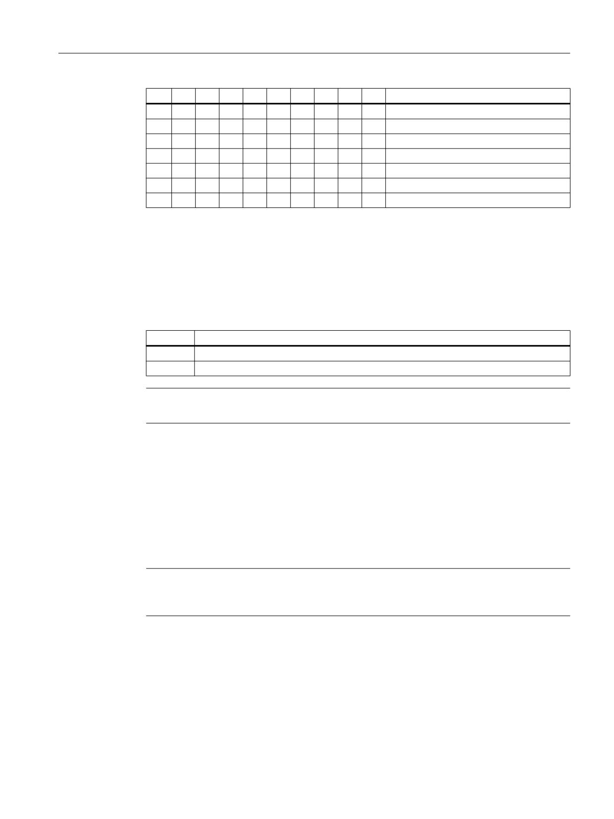
MCP Interface PN
10.2 Interfaces
1
2
3
4
5
6
7
8
9
10
Meaning
off
on
off
off
off
off
on
on
MCP address 194
on
off
off
off
off
off
on
on
MCP address 193
off
off
off
off
off
off
on
on
MCP address 192
x
x
x
x
x
x
x
x
"
on
off
off
off
off
off
off
off
MCP address 001
off
off
off
off
off
off
off
off
MCP address 000
You can find the settings for the basic PLC program in:
Function Manual, Basic Functions (P3 sl)
Switch S2
The handwheel signal type is set with switch S2-1.
Table 10-25 Switch S2 settings
1
Meaning
on
differential interface
off
TTL interface
Note
Switch S2-2 is reserved for test purposes.
10.2.4
Input / output images
Standard + two handwheels
The specifications for assigning input and output bytes listed in the tables can be changed in
the PLC via parameter assignment. The inputs/outputs can be accessed word-oriented.
Note
The following applies for the process input and output images in the tables: n is defined by
means of FB1 parameters in OB100 of the PLC.
Machine control panels
Manual, 03/2016, 6FC5397-1AP40-5BA3
345

MCP Interface PN
10.2 Interfaces
Table 10-26
MCP Interface PN input image
Byte
Bit7
Bit6
Bit5
Bit4
Bit3
Bit2
Bit1
Bit0
EB n + 0
IN0[7]
IN0[6]
IN0[5]
IN0[4]
IN0[3]
IN0[2]
IN0[1]
IN0[0]
X111.17
X111.15
X111.13
X111.11
X111.9
X111.7
X111.5
X111.3
EB n + 1
IN0[15]
IN0[14]
IN0[13]
IN0[12]
IN0[11]
IN0[10]
IN0[9]
IN0[8]
X111.33
X111.31
X111.29
X111.27
X111.25
X111.23
X111.21
X111.19
EB n + 2
IN1[7]
IN1[6]
IN1[5]
IN1[4]
IN1[3]
IN1[2]
IN1[1]
IN1[0]
X112.17
X112.15
X112.13
X112.11
X112.9
X112.7
X112.5
X112.3
EB n + 3
IN1[15]
IN1[14]
IN1[13]
IN1[12]
IN1[11]
IN1[10]
IN1[9]
IN1[8]
X112.33
X112.31
X112.29
X112.27
X112.25
X112.23
X112.21
X112.19
EB n + 4
IN2[7]
IN2[6]
IN2[5]
IN2[4]
IN2[3]
IN2[2]
IN2[1]
IN2[0]
X113.17
X113.15
X113.13
X113.11
X113.9
X113.7
X113.5
X113.3
EB n + 5
IN2[15]
IN2[14]
IN2[13]
IN2[12]
IN2[11]
IN2[10]
IN2[9]
IN2[8]
X113.33
X113.31
X113.29
X113.27
X113.25
X113.23
X113.21
X113.19
EB n + 6
IN3[7]
IN3[6]
IN3[5]
IN3[4]
IN3[3]
IN3[2]
IN3[1]
IN3[0]
X114.17
X114.15
X114.13
X114.11
X114.9
X114.7
X114.5
X114.3
EB n + 7
IN3[15]
IN3[14]
IN3[13]
IN3[12]
IN3[11]
IN3[10]
IN3[9]
IN3[8]
X114.33
X114.31
X114.29
X114.27
X114.25
X114.23
X114.21
X114.19
EB n + 8
IN4[7]
IN4[6]
IN4[5]
IN4[4]
IN4[3]
IN4[2]
IN4[1]
IN4[0]
X112.38
X112.37
X112.36
X112.35
X111.38
X111.37
X111.36
X111.35
EB n + 9
IN4[15]
IN4[14]
IN4[13]
IN4[12]
IN4[11]
IN4[10]
IN4[9]
IN4[8]
X114.38
X114.37
X114.36
X114.35
X113.38
X113.37
X113.36
X113.35
EB n + 10
Temperature alarms *)
OV_VS16
OV_VS8
OV_VS4
OV_VS2
OV_VS1
X30.6
X30.7
X30.8
X30.9
X30.10
T_Critical
T_High
T_Low
EB n + 11
-
-
-
OV_SP16
OV_SP8
OV_SP4
OV_SP2
OV_SP1
X31.6
X31.7
X31.8
X31.9
X31.10
EB n + 12
IN6[7]
IN6[6]
IN6[5]
IN6[4]
IN6[3]
IN6[2]
IN6[1]
IN6[0]
X55.2
X55.1
X52.3
X52.2
X52.1
X51.3
X51.2
X51.1
EB n + 13
IN_24V[5]
IN_24V[4]
IN_24V[3]
IN_24V[2]
IN_24V[1]
IN_24V[0]
-
IN6[8]
X41.3
X41.2
X41.1
X40.3
X40.2
X40.1
X55.3
*)
A logical 1 in the appropriate bit means that the associated temperature alarm is present.
The GSDML-V2.1-siemens-sinumerik-mcpRT-20111001.xml file is required to configure the
PROFINET. The module must be configured as MCP/MPP universal component on slot 1.
Machine control panels
346
Manual, 03/2016, 6FC5397-1AP40-5BA3
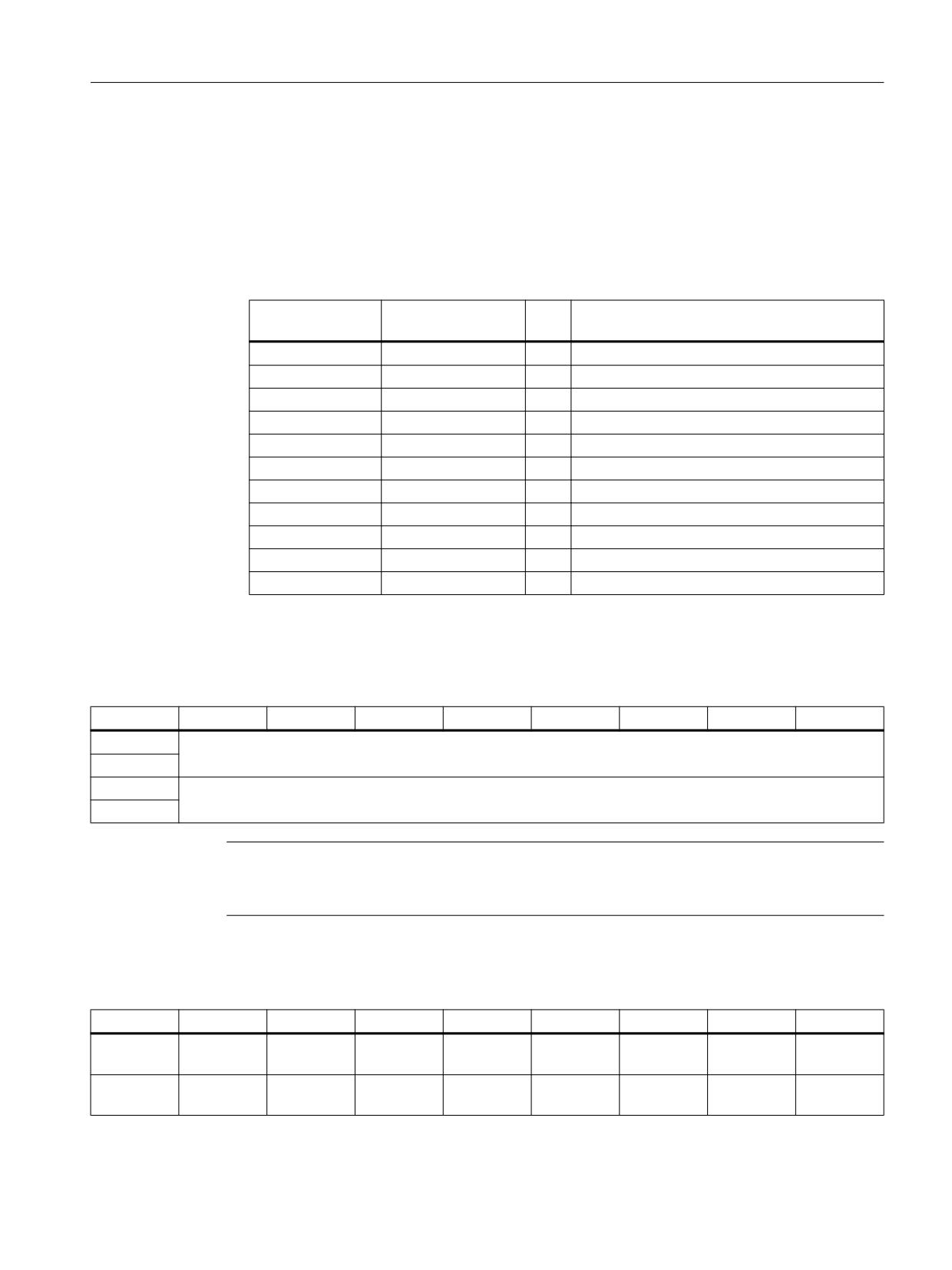
MCP Interface PN
10.2 Interfaces
This expands the input image by two further bytes:
● EB n + 14: Current temperature of the module measured in degrees Celsius.
The measured value of temperature sensor LM77 is represented as an integer value in 8-
bit one's complement.
Theoretically representable value range: -127 °C to +127 °C.
Real value range of temperature sensor LM77: -55 °C to +125 °C.
For examples, see table:
*)
Temperature in °C
Representation in
Meaning
byte EB n + 14
+0 = T_Low
00000000 = 0x00
0
Prewarning level for lower ambient temperature
+1
00000001 = 0x01
1
+70 = T_High
01000110 = 0x46
70
Prewarning level for upper ambient temperature
+75 = T_Critical
01001011 = 0x4B
75
Max. permissible ambient temperature
+127
01111111 = 0x7F
127
-127
10000000 = 0x80
128
-0
11111111 = 0xFF
255
*)
Interpreted as an unsigned figure
● EB n + 15: Identifier for the 'MCP Interface PN' module: 0x8D
Table 10-27 Input image for handwheel data
Byte
Bit7
Bit6
Bit5
Bit4
Bit3
Bit2
Bit1
Bit0
EB m + 0
Handwheel 1 counter status
(16-bit signed, low-order byte equals byte m + 0)
EB m + 1
EB m + 2
Handwheel 2 counter status
(16-bit signed, low-order byte equals byte m + 2)
EB m + 3
Note
Within the SINUMERIK control, the handwheel data is processed directly by the NCK and is
not available to the PLC.
Table 10-28 MCP Interface PN output image
Byte
Bit7
Bit6
Bit5
Bit4
Bit3
Bit2
Bit1
Bit0
AB n + 0
OUT0[7]
OUT0[6]
OUT0[5]
OUT0[4]
OUT0[3]
OUT0[2]
OUT0[1]
OUT0[0]
X111.18
X111.16
X111.14
X111.12
X111.10
X111.8
X111.6
X111.4
AB n + 1
OUT0[15]
OUT0[14]
OUT0[13]
OUT0[12]
OUT0[11]
OUT0[10]
OUT0[9]
OUT0[8]
X111.34
X111.32
X111.30
X111.28
X111.26
X111.24
X111.22
X111.20
Machine control panels
Manual, 03/2016, 6FC5397-1AP40-5BA3
347
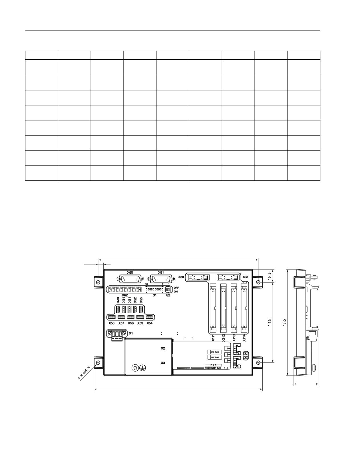
MCP Interface PN
10.3 Mounting
Byte
Bit7
Bit6
Bit5
Bit4
Bit3
Bit2
Bit1
Bit0
AB n + 2
OUT1[7]
OUT1[6]
OUT1[5]
OUT1[4]
OUT1[3]
OUT1[2]
OUT1[1]
OUT1[0]
X112.18
X112.16
X112.14
X112.12
X112.10
X112.8
X112.6
X112.4
AB n + 3
OUT1[15]
OUT1[14]
OUT1[13]
OUT1[12]
OUT1[11]
OUT1[10]
OUT1[9]
OUT1[8]
X112.34
X112.32
X112.30
X112.28
X112.26
X112.24
X112.22
X112.20
AB n + 4
OUT2[7]
OUT2[6]
OUT2[5]
OUT2[4]
OUT2[3]
OUT2[2]
OUT2[1]
OUT2[0]
X113.18
X113.16
X113.14
X113.12
X113.10
X113.8
X113.6
X113.4
AB n + 5
OUT2[15]
OUT2[14]
OUT2[13]
OUT2[12]
OUT2[11]
OUT2[10]
OUT2[9]
OUT2[8]
X113.34
X113.32
X113.30
X113.28
X113.26
X113.24
X113.22
X113.20
AB n + 6
OUT3[7]
OUT3[6]
OUT3[5]
OUT3[4]
OUT3[3]
OUT3[2]
OUT3[1]
OUT3[0]
X114.18
X114.16
X114.14
X114.12
X114.10
X114.8
X114.6
X114.4
AB n + 7
OUT3[15]
OUT3[14]
OUT3[13]
OUT3[12]
OUT3[11]
OUT3[10]
OUT3[9]
OUT3[8]
X114.34
X114.32
X114.30
X114.28
X114.26
X114.24
X114.22
X114.20
AB n + 8
OUT_24V
OUT_24V
OUT_24V
OUT_24V
OUT_24V
OUT_24V
OUT_24V
OUT_24V
[7] X56.2
[6] X56.1
[5] X53.3
[4] X53.2
[3] X53.1
[2] X54.3
[1] X54.2
[0] X54.1
AB n + 9
-
OUT_24V
OUT_24V
OUT_24V
OUT_24V
OUT_24V
OUT_24V
OUT_24V
[14] X58.3
[13] X58.2
[12] X58.1
[11] X57.3
[10] X57.2
[9] X57.1
[8] X56.3
10.3
Mounting
The module can be attached at a suitable position via the four mounting holes (e.g. behind the
machine control panel or in the control cabinet). The selection of the appropriate mounting
position depends on the interfaces used and the associated maximum cable lengths.
Four standard torx-slotted screws T20/M4 are used to attach the module.
Image 10-8 MCP Interface PN dimension drawing
Machine control panels
348
Manual, 03/2016, 6FC5397-1AP40-5BA3
MCP Interface PN
10.4 Technical data
10.4
Technical data
Safety
Safety class
III according to EN60204-1
Degree of protection ac-
IP00
cording to EN 60529
Approvals
CE / cULus
Electrical data
Input voltage
24 VDC
Typical current consump-
min. 0.1 A 1) / max. 2.6 A 2)
tion
Power consumption, max.
Board:
Handwheels:
Lamps:
LEDs:
Total:
2.4 W
2 x 0.9 W
54 W
4 W
62.4 W
(15 x 3.6 W)
(80 x 0.05 W)
Mechanical data
Dimensions (W x H x D)
242 x 152 x 36 mm
Weight
557 g
1) Without connection (no handwheels, no loading of the outputs ...)
2) Max. connection with two handwheels, two rotary override switches, loading of the 24 V outputs ...
Note
Information about the climatic and mechanical environmental conditions is contained in the
associated section under:
"General notes and interconnection" → "Operational planning".
Machine control panels
Manual, 03/2016, 6FC5397-1AP40-5BA3
349
MCP Interface PN
10.4 Technical data
Machine control panels
350
Manual, 03/2016, 6FC5397-1AP40-5BA3