SINUMERIK 840D sl Hardware. Manual (2011-2020) - page 10

Machine control panel: MCP 310
3.9 Accessories and spare parts
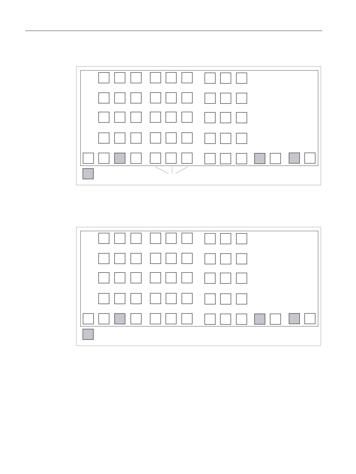
Preparing the slide-in labels with the aid of "Template_MCP310.doc" (B)
Inserting symbols with the"Symbols.doc" file (C)
1. Open both the "Template_MCP310.doc" file and the "Symbols.doc" file in MS Word.
2. Copy the desired key symbol from the "Symbols.doc" file (C).
3. Position the cursor in the desired field of the template (B) and add the symbol.
4. If all the desired symbols have been added, remove the separating lines and start the
printing process in accordance with the instructions in Section: Preparing the slide-in labels
with the aid of "Template_M_MCP310.doc".
Inserting characters/text
1. Open the "Template_MCP310.doc" file in MS Word.
2. Set the "Arial" font to format characters.
(This font is comparable to the "Univers S57" font, used by Siemens for the key labeling.)
3. Position the cursor in the desired table cell and enter characters/text.
Creating your own symbols
● Printing in a vector program (e.g. Designer, Freehand, CorelDraw):
- Draw a 15 x 15 mm square, fill with the color white and give it an invisible border line.
- Place the symbol in the center of this square.
- Copy the entire image (square and symbol) and paste it into the Word document
(Template_MCP310.doc).
● Drawing in an image editing program (e.g. Photoshop, Picture Publisher, Paint):
- Create a square area (e.g. 100 x 100 pixels) filled with the color white.
- Draw the symbol in the center of this square.
- Copy the entire image (square and symbol) and paste it into the Word document
(Template_MCP310.doc).
Dimensions
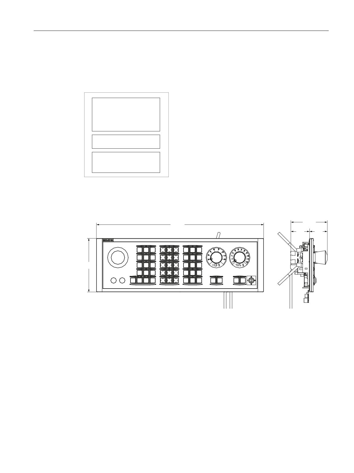
The figure shows a dimension drawing for the blank template of the MCP 310 (thickness: 0.6
mm):
D
D
D
E
D
D
D
D
E
D
D
D
F
a
= 19 mm
b
= 4 mm
c
= 30.5 mm
Image 3-15 Dimension drawing for slide-in labels
Machine control panels
78
Manual, 03/2016, 6FC5397-1AP40-5BA3
Machine control panel: MCP 310
3.9 Accessories and spare parts
3.9.3
Using the slide-in label "Teil1"
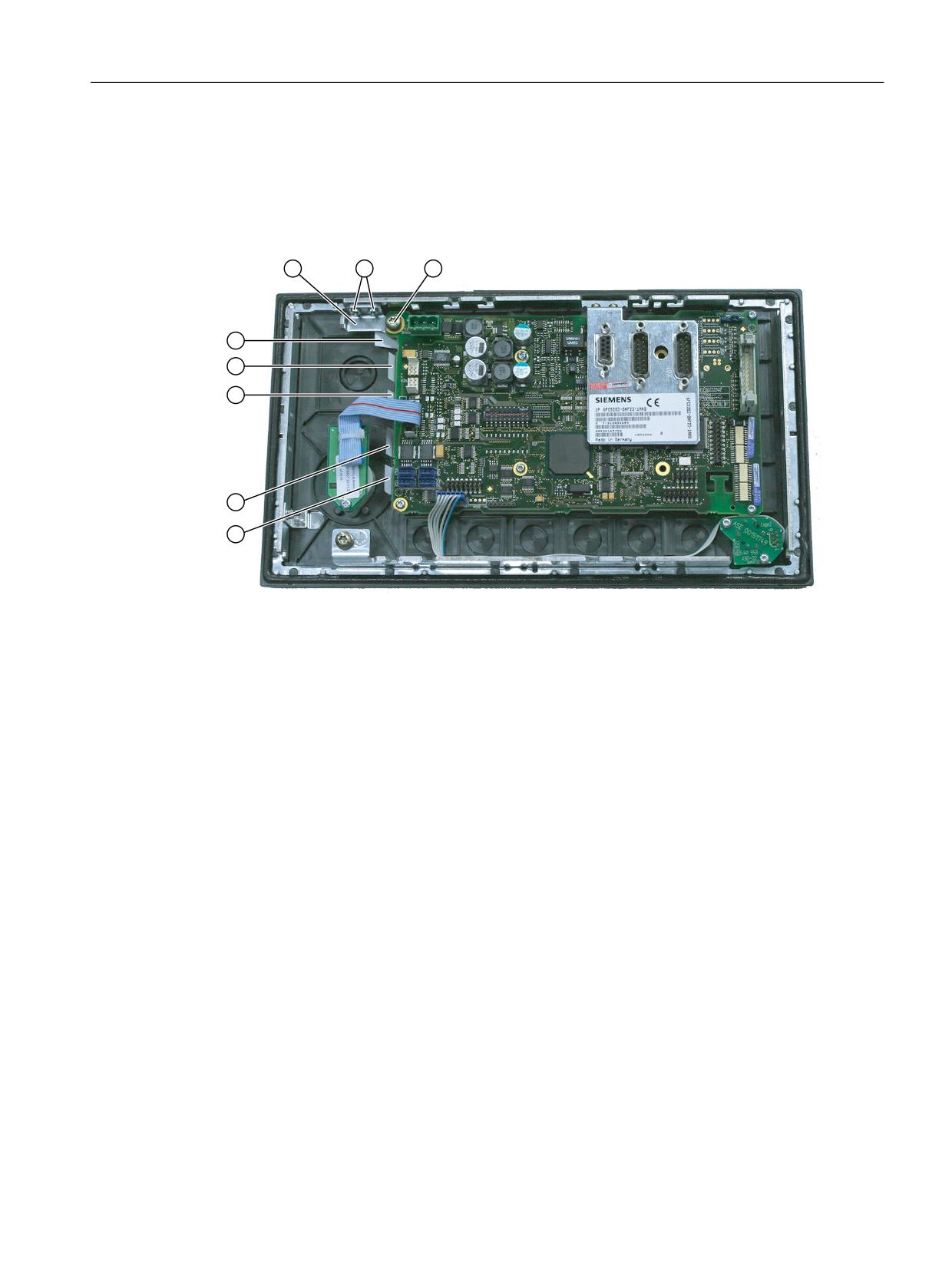
The slide-in label "Teil1" ⑧ is located below the grounding bracket ①.
Therefore, first remove the grounding bracket before you pull out or insert the slide-in label
"Teil1".
① Grounding bracket
② Fastening screws (M3) for the grounding bracket (housing)
③ Fastening screw (M5) for the grounding bracket (COM board)
④ Slide-in label "Teil5"
⑤ Slide-in label "Teil4"
⑥ Slide-in label "Teil3"
⑦ Slide-in label "Teil2"
⑧ Slide-in label "Teil1"
Image 3-16 MCP 310 - Rear side with slide-in labels
Machine control panels
Manual, 03/2016, 6FC5397-1AP40-5BA3
79
Machine control panel: MCP 310
3.9 Accessories and spare parts
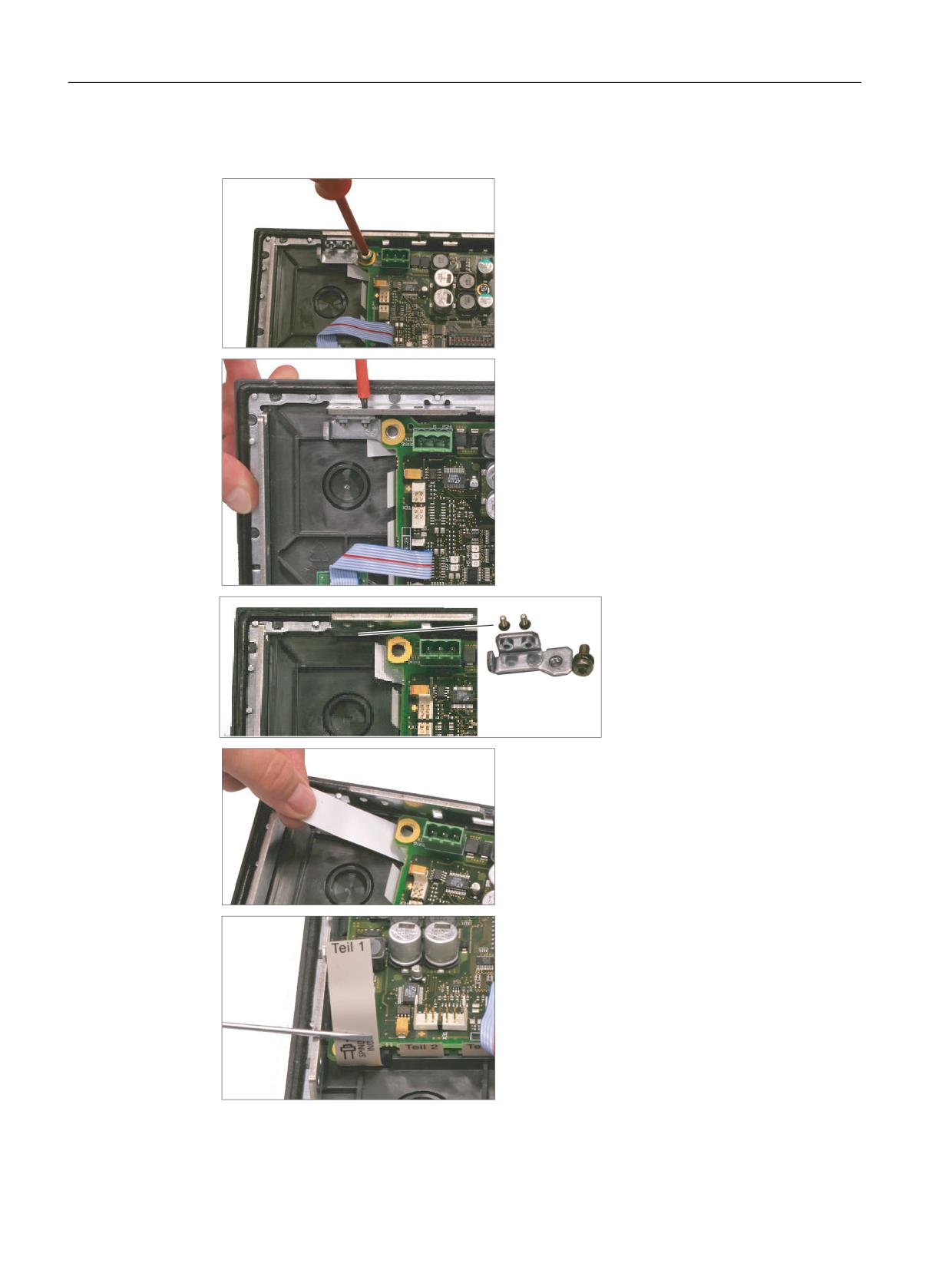
Removing the grounding bracket
1.Remove the fastening screw (M5) using a
TX25 screwdriver.
2.Remove the two fastening screws (M3) using
a TX10 screwdriver.
3.Take off the grounding brack-
et.
4.Pull out the slide-in label.
Machine control panels
80
Manual, 03/2016, 6FC5397-1AP40-5BA3
Machine control panel: MCP 310
3.9 Accessories and spare parts
Installing the grounding bracket
Secure the grounding bracket after you have inserted the slide-in label by tightening the three
fastening screws.
Note
Observe the proper torque values when tightening the screws:
- M3: 0.8 to 1.3 Nm
- M5: 3.0 to 6.0 Nm
Machine control panels
Manual, 03/2016, 6FC5397-1AP40-5BA3
81
Machine control panel: MCP 310
3.9 Accessories and spare parts
Machine control panels
82
Manual, 03/2016, 6FC5397-1AP40-5BA3
Machine control panel: MCP 483C PN
4
4.1
Description
Machine control panel MCP 483C PN (PN = PROFINET) enables user-friendly operation of
the machine functions. It is suitable for machine-level operation of milling, turning, grinding
and special machines.
Note
The IE functionality (IE = Industrial Ethernet) is still included and preset.
Please note the switch position of S2.
All keys are designed with replaceable covers for machine-specific adaptations. The key
covers can be freely inscribed using a laser. Clear key covers can be used as an alternative.
The machine control panel is secured from the rear with special clamps supplied with the panel.
Validity
This description applies to the machine control panel:
Type
Key type
Article number
MCP 483C PN
Mechanical short-stroke keys
6FC5303-0AF22-0AA1
The safety-related accessories / spare parts are marked in the "Accessories and spare parts"
section with *).
Features
Control elements:
● Mechanical short-stroke keys
● Operating mode and function keys:
-
50 keys with assigned LEDs, 17 freely assignable customer keys in the standard
assignment
- Arrow keys for milling machines with rapid traverse override
(The key covers for the arrow keys for turning machines are supplied, see Section Front
side (Page 85))
● Spindle control with override spindle (rotary switch with 16 positions)
● Feed control with override feed / rapid traverse (rotary switch with 23 positions)
● Keyswitch (four positions and three different keys)
● Emergency Stop button, two contact blocks (1 NO + 1 NC)
Machine control panels
Manual, 03/2016, 6FC5397-1AP40-5BA3
83
Machine control panel: MCP 483C PN
4.1 Description
Interfaces:
● Ethernet (transfer rate: 10/100 Mbit/s; for IE and PN)
● Nine customer-specific inputs (e.g. for illuminated pushbuttons)
● Six customer-specific outputs
● Connection for two handwheels (Sub-D)
(velocity input and contour handwheel are only possible if connecting through the
handwheel connection module 6FC5303-0AA02-0AA0 or the MCP PN interface
6FC5303-0AF03-0AA0)
Expansion slots:
Two slots for control devices (d = 16 mm).
(additional cable set required for control devices, see Table 4-4 Accessories and spare parts
for machine control panel 483C PN (Page 97))
Machine control panels
84
Manual, 03/2016, 6FC5397-1AP40-5BA3
Machine control panel: MCP 483C PN
4.2 Operating and display elements
4.2
Operating and display elements
4.2.1
Front side
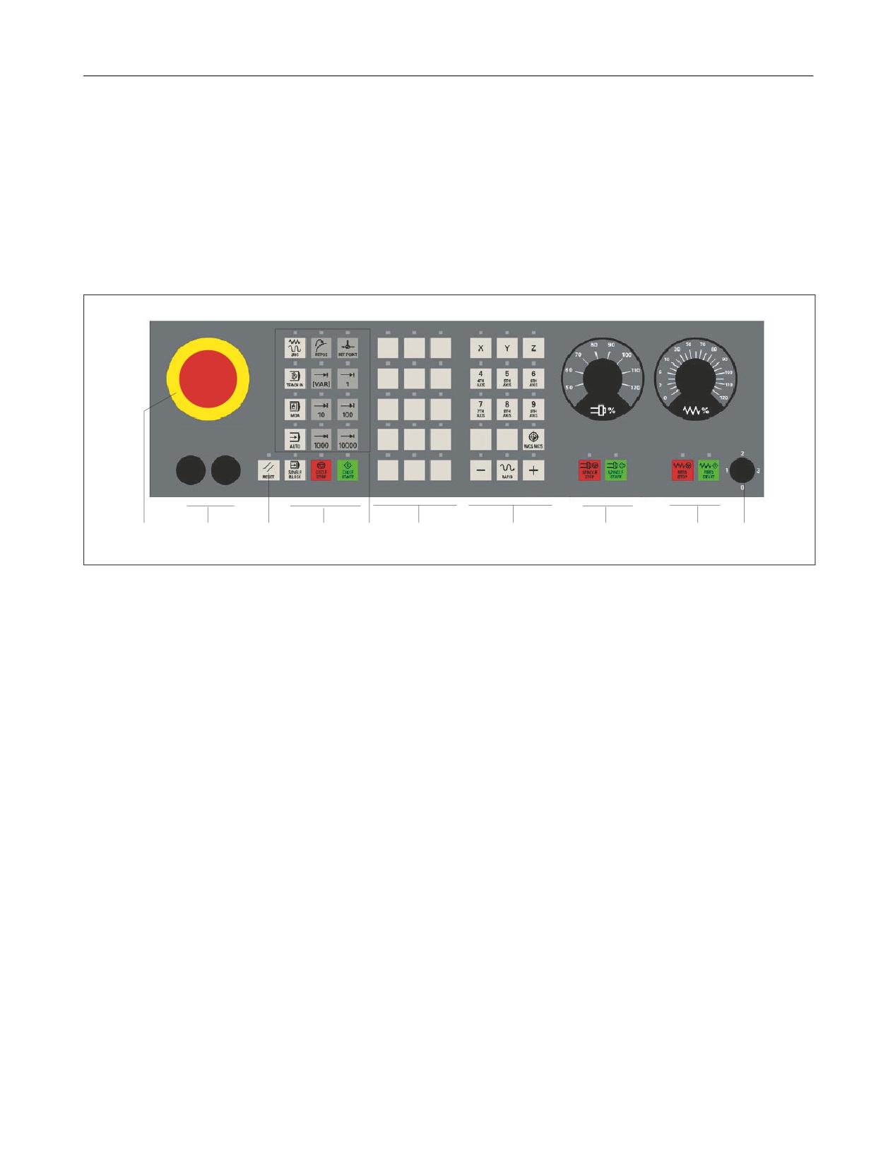
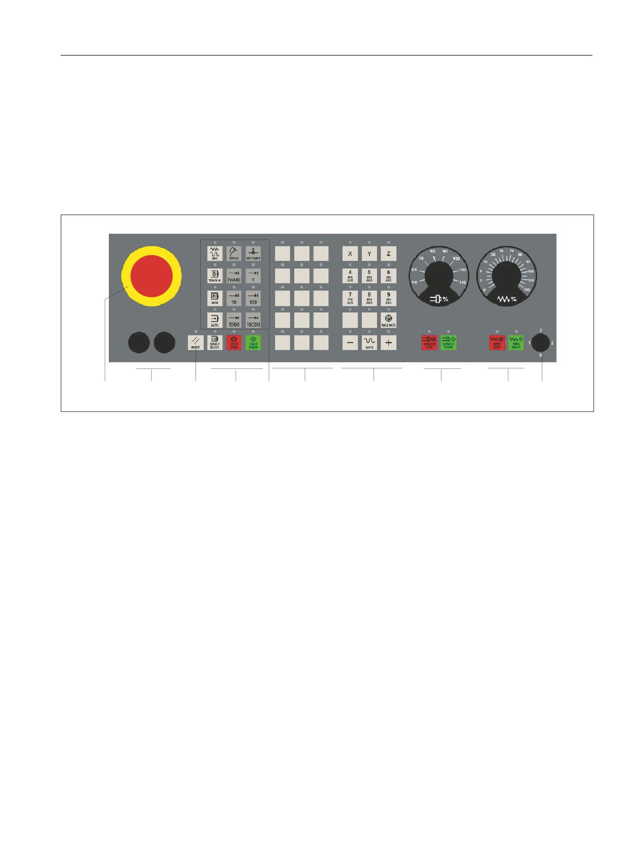
Overview
(1)
Emergency stop button
(2)
Slots for control devices (d = 16 mm)
(3)
Reset button
(4)
Program control
(5)
Operating modes, machine functions
(6)
User keys T1 to T15
(7)
Direction keys with rapid traverse override (R1 to R15)
(8)
Spindle control with override switch
(9)
Feed control with override switch
(10)
Keyswitch (four positions)
Image 4-1
Position of control elements on MCP 483C PN
Machine control panels
Manual, 03/2016, 6FC5397-1AP40-5BA3
85
Machine control panel: MCP 483C PN
4.2 Operating and display elements
Emergency stop button
Emergency stop button
Press the red emergency stop button in emergencies if
∎ people are at risk,
∎ there is the danger of machines or the workpiece being damaged.
As a rule, when operating the emergency stop button, all drives are brought
to a standstill with max. braking torque.
Turn the EMERGENCY STOP button counterclockwise to unlatch it.
Machine manufacturer
For other reactions to the emergency stop:
Refer to the specifications of the machine tool manufacturer
WARNING
Danger of death resulting from the premature emergency stop unlocking
If you have shut down the system to be monitored, you can only release the emergency stop
button or put the system to be monitored back into operation if the condition that triggered
the emergency stop function has been corrected and a safe restart is carried out.
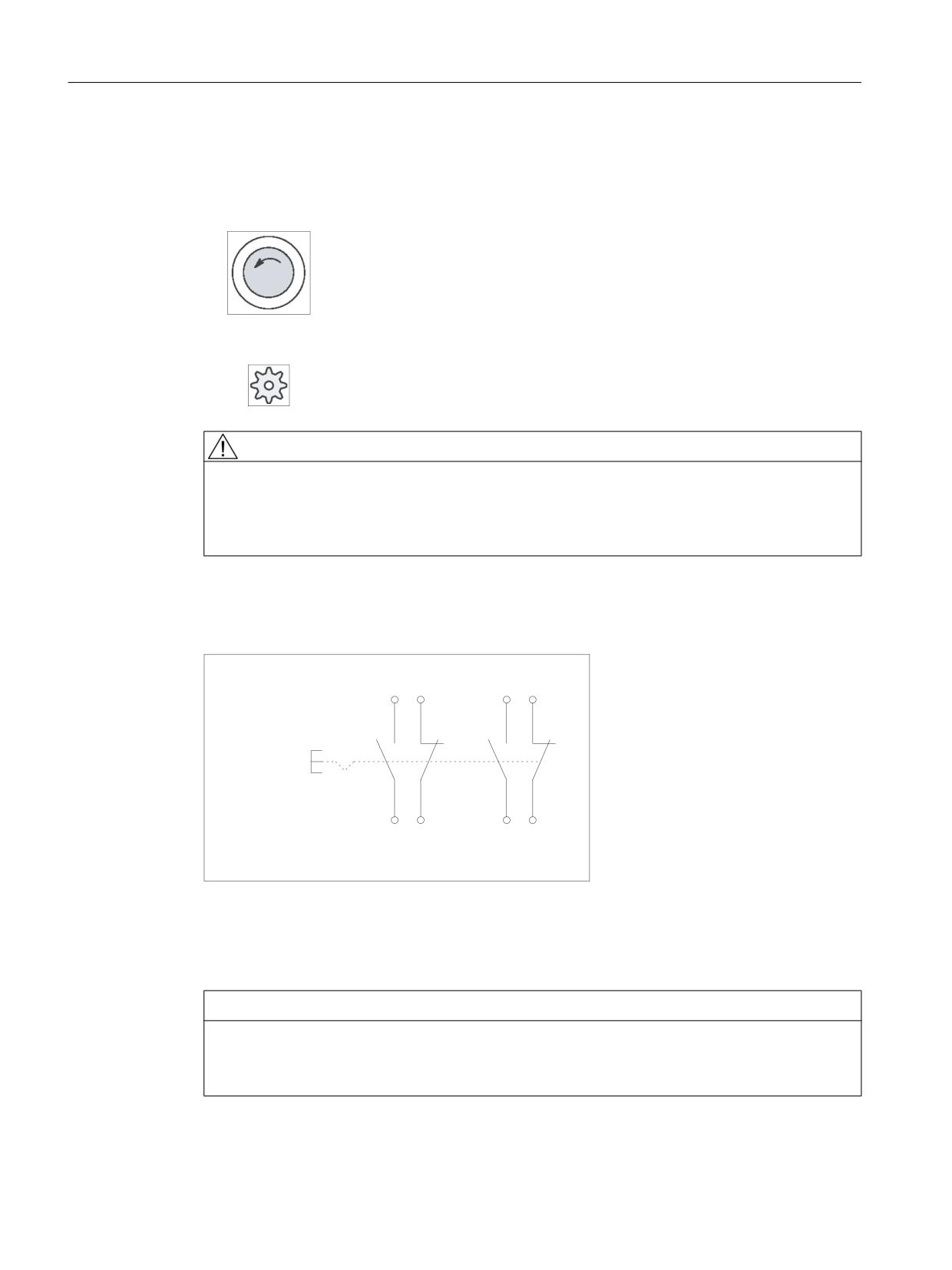
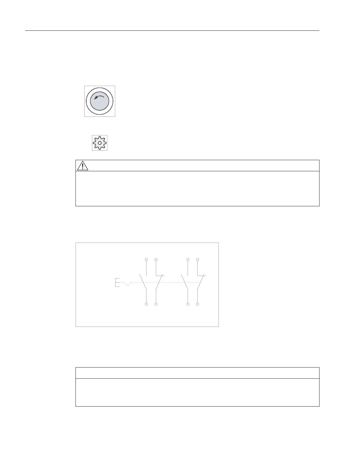
Emergency stop circuit
(0(5*(1&<
6723
Image 4-2
Emergency stop circuit
Slots for control devices
NOTICE
Damage to the front
The openings for mounting control devices (2) in Fig. "Position of control elements of
MCP 483C PN" must not be knocked out, but drilled to the required width.
Machine control panels
86
Manual, 03/2016, 6FC5397-1AP40-5BA3
Machine control panel: MCP 483C PN
4.2 Operating and display elements
Key covers
All keys of the MCP 483C PN come with changeable key covers.
Refer to the following table for the additional replacement key covers provided for turning
machines in the accessories pack.
Key cover
Symbol number
Key cover
Symbol number
7027
7129
;
7125
7130
&
<
7126
7131
;
=
7127
7132
<
&
7128
=
The article numbers for the key covers can be found in Section "Accessories and spare parts".
Machine control panels
Manual, 03/2016, 6FC5397-1AP40-5BA3
87
Machine control panel: MCP 483C PN
4.2 Operating and display elements
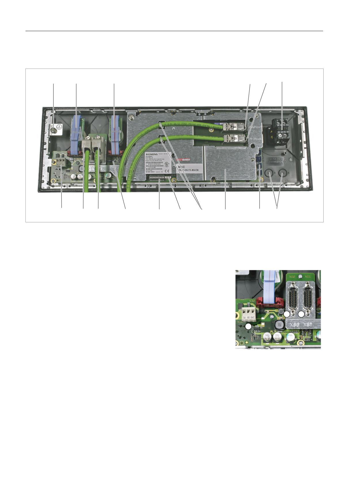
4.2.2
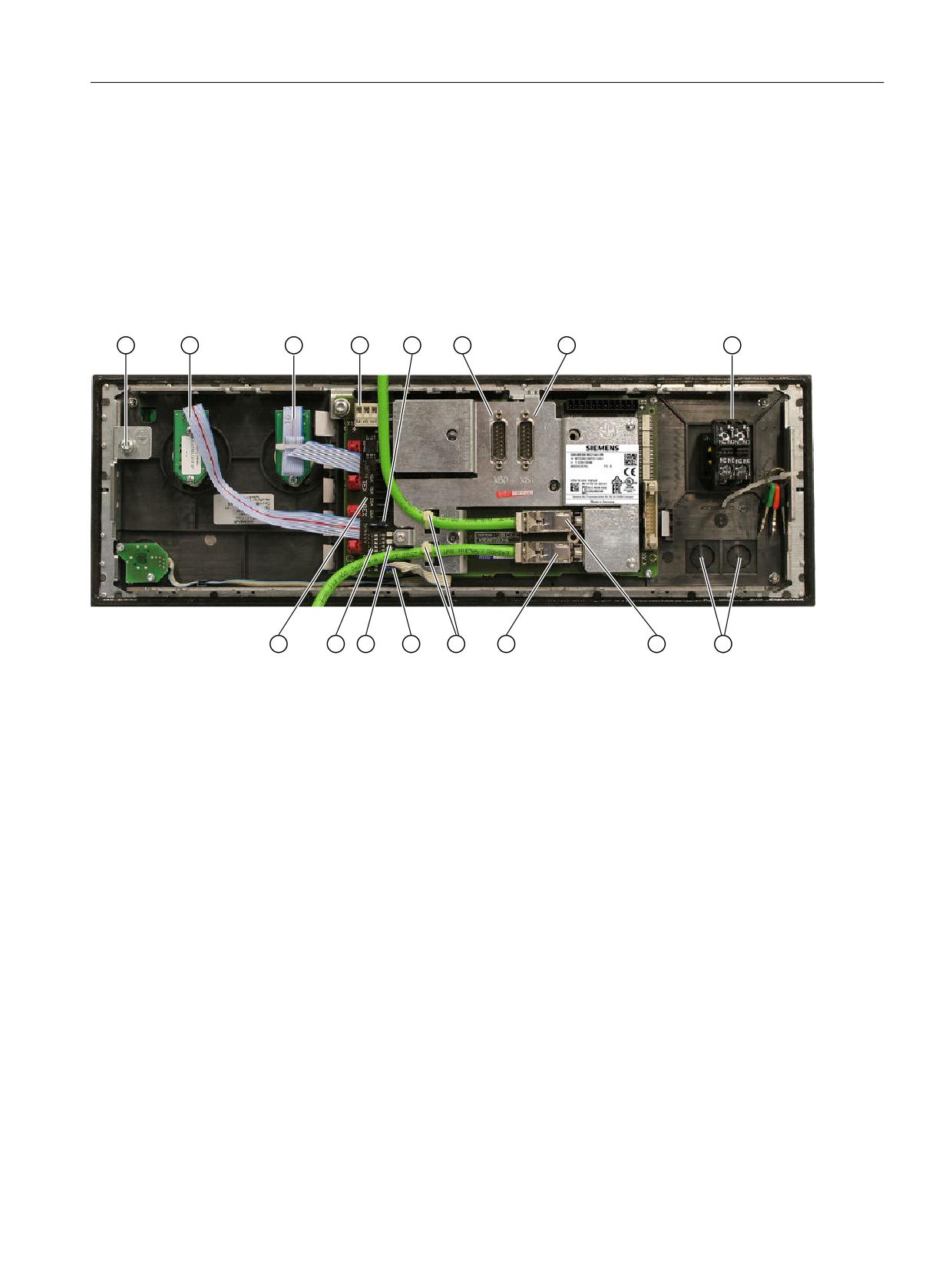
Rear side
(1)
Ground terminal
(2)
Feed override
X30
(3)
Spindle override
X31
(4)
Ethernet connection (mechan. secured - Port1
X20
(5)
Ethernet connection (mechan. secured - Port2
X21
(6)
EMERGENCY STOP
(7)
Installation locations for additional control devices (d = 16 mm)
(8)
Customer-specific inputs and outputs
(9)
Cover plate
(10)
Ethernet cable strain relief
(11)
LEDs (see detailed figure)
(12)
Switch S2
(13)
Switch S1
(14)
Handwheel connection
X61
(15)
Handwheel connection
X60
Details excerpt
(16)
Power supply interface
X10
Image 4-3
Rear of MCP 483C PN with connecting cable (handwheel/Ethernet)
Machine control panels
88
Manual, 03/2016, 6FC5397-1AP40-5BA3
Machine control panel: MCP 483C PN
4.3 Interfaces
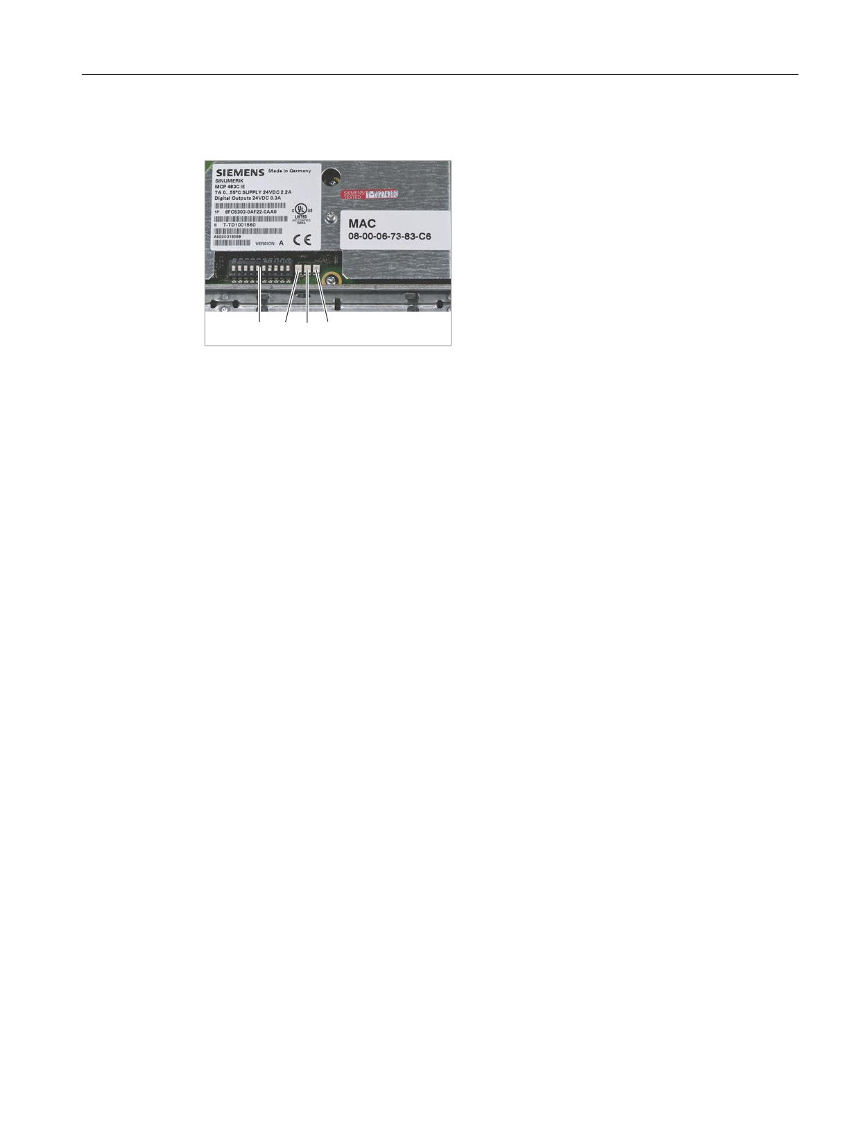
LEDs
(1)
Switch S2
(2)
H1 - POWER OK (green)
(3)
LEDs
H2 - BUSSYNC
(4)
H3 - BUSFAULT
Image 4-4
MCP 483C PN - LEDs
4.3
Interfaces
4.3.1
Overview
Overview
X10
Power supply interface
X20
Ethernet port 1
X21
Ethernet port 2
X30
Interface for rotary switch feed override
X31
Interface for rotary switch spindle override
X51 / X52 / X55
Interfaces for customer-specific inputs
X53 / X54
Interfaces for customer-specific outputs
X60 / X61
Connections for 2 handwheels (TTL / differential - can be set with switch S1)
4.3.2
Description
Pin assignment
For more detailed information, see "General information and networking", Chapter:
"Connecting".
Machine control panels
Manual, 03/2016, 6FC5397-1AP40-5BA3
89
Machine control panel: MCP 483C PN
4.3 Interfaces
Switch S1/S2
Settings, see Chapter "Machine control panel: MCP 310C PN", Section "Interfaces".
4.3.3
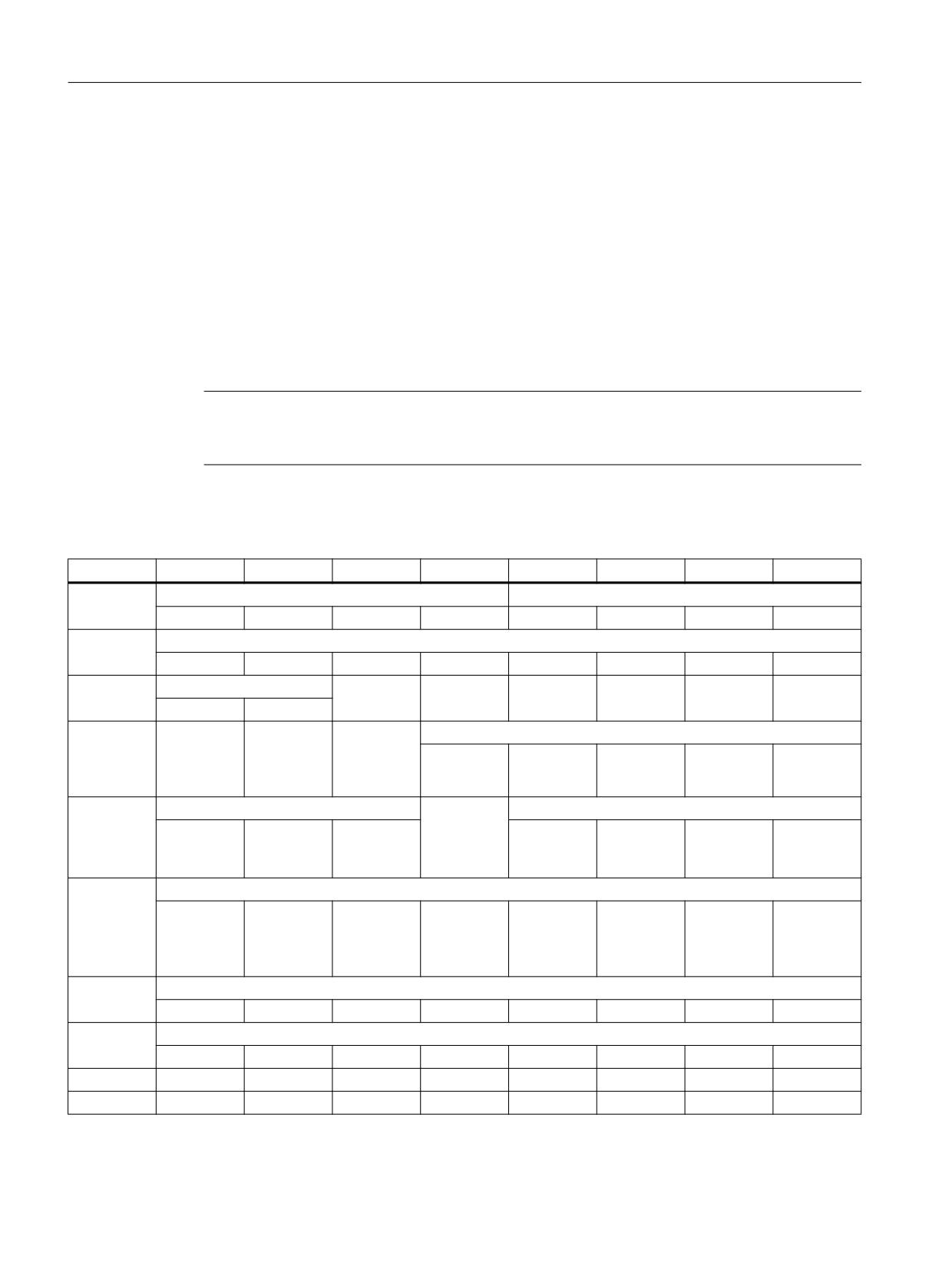
Input / output images
Standard + two handwheels
The specifications for assigning input and output bytes listed in the tables can be changed in
the PLC via parameter assignment.
Note
The following applies in respect of the process input and output images in the tables: n is
defined by means of FB1 parameters in OB100 of the PLC.
Table 4-1
Process input image for MCP 483C PN
Byte
Bit7
Bit6
Bit5
Bit4
Bit3
Bit2
Bit1
Bit0
EB n + 0
Spindle override
Mode
D (23)
C (22)
B (21)
A (20)
JOG
TEACH IN
MDA
AUTO
EB n + 1
Machine function
REPOS
REF.
var. INC
10000 INC
1000 INC
100 INC
10 INC
1 INC
EB n + 2
Key-operated switch
Spindle
* Spindle
Feed
* Feed
NC
* NC
start
stop
start
stop
start
stop
Position 0
Position 2
EB n + 3
RESET
Key-operat-
Single
Feed override
ed
block
E (24)
D (23)
C (22)
B (21)
A (20)
switch
position 1
EB n + 4
Arrow keys
Key-operat-
Axis selection
ed
+
-
Rapid tra-
X
4. axis
7. axis
switch
R15
R13
verse
R1
R4
R7
R10
position 3
R14
EB n + 5
Axis selection
Y
Z
5. axis
Motion
9. axis
8. axis
6. axis
R2
R3
R5
command
R11
R9
R8
R6
in
MCS/WCS
EB n + 6
Unassigned customer keys
T9
T10
T11
T12
T13
T14
T15
-
EB n + 7
Unassigned customer keys
T1
T2
T3
T4
T5
T6
T7
T8
EB n + 8
-
-
-
-
-
-
-
-
EB n + 9
-
-
-
-
-
-
-
-
Machine control panels
90
Manual, 03/2016, 6FC5397-1AP40-5BA3
Machine control panel: MCP 483C PN
4.3 Interfaces
Byte
Bit7
Bit6
Bit5
Bit4
Bit3
Bit2
Bit1
Bit0
EB n + 10
KT-IN8
KT-IN7
KT-IN6
KT-IN5
KT-IN4
KT-IN3
KT-IN2
KT-IN1
X55.2
X55.1
X52.3
X52.2
X52.1
X51.3
X51.2
X51.1
EB n + 11
-
-
-
-
-
-
-
KT-IN9
X55.3
EB n + 12
-
-
-
-
-
-
-
-
EB n + 13
-
-
-
X31
X31
X31
X31
X31
pin 6 1)
pin 7 1)
pin 8 1)
pin 9 1)
pin 10 1)
Signals marked with * are inverse signals.
1)
If the 4-stage rotary spindle override switch on X31 is replaced by a 5-stage rotary switch, the input information here
can be measured in five stages.
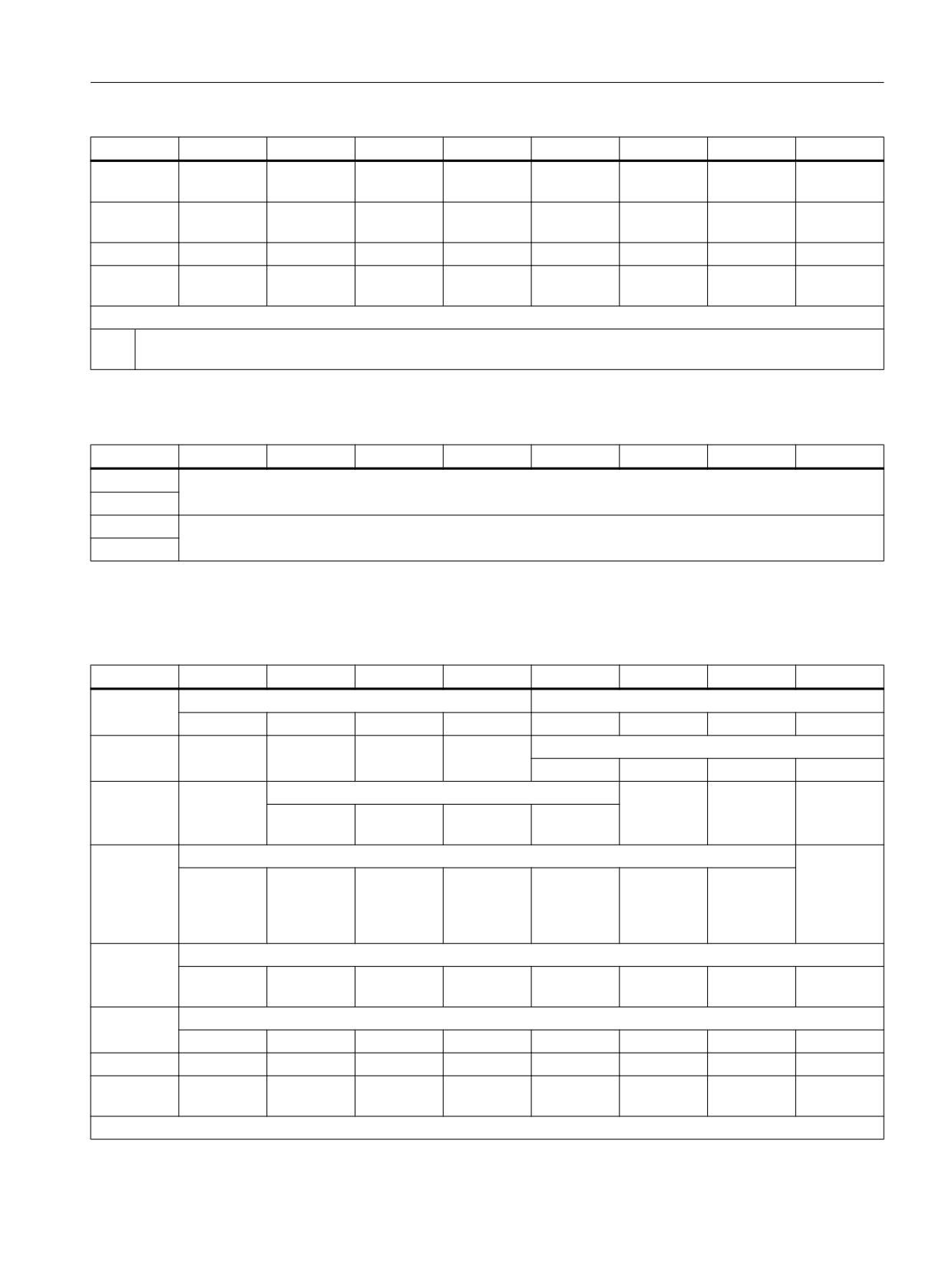
Table 4-2
Input image for handwheel data
Byte
Bit7
Bit6
Bit5
Bit4
Bit3
Bit2
Bit1
Bit0
EB n + 14
Handwheel 1 counter status
(16-bit signed, low-order byte equals byte n+14)
EB n + 15
EB n + 16
Handwheel 2 counter status
(16-bit signed, low-order byte equals byte n+16)
EB n + 17
Within the SINUMERIK controller, the handwheel data is processed directly by the NCK and
are not available to the PLC.
Table 4-3
Process output image for MCP 483C PN
Byte
Bit7
Bit6
Bit5
Bit4
Bit3
Bit2
Bit1
Bit0
AB n + 0
Machine function
Mode
1000 INC
100 INC
10 INC
1 INC
JOG
TEACH IN
MDA
AUTO
AB n + 1
Feed
* Feed
NC
* NC
Machine function
start
stop
start
stop
REPOS
REF.
var. INC
10000 INC
AB n + 2
Arrow
Axis selection
Single
Spindle
*Spindle
key -
block
Start
Stop
X
4. axis
7. axis
R13
R1
R4
R7
R10
AB n + 3
Axis selection
Arrow
key +
Z
5. axis
Motion
9. axis
8. axis
6. axis
R3
R5
command
R11
R9
R8
R6
R15
in
MCS/WCS
AB n + 4
Unassigned customer keys
T9
T10
T11
T12
T13
T14
T15
Y
R2
AB n + 5
Unassigned customer keys
T1
T2
T3
T4
T5
T6
T7
T8
AB n + 6
-
-
-
-
-
-
RESET
R14
AB n + 7
-
-
KT-OUT6
KT-OUT5
KT-OUT4
KT-OUT3
KT-OUT2
KT-OUT1
X54.3
X54.2
X54.1
X53.3
X53.2
X53.1
Signals marked with * are inverse signals
Machine control panels
Manual, 03/2016, 6FC5397-1AP40-5BA3
91
Machine control panel: MCP 483C PN
4.3 Interfaces
Default key assignment
-2*
REP
REF
(T1)
(T2)
(T3)
X
Y
Z
(R1)
(R2)
(R3)
TCH
INC
INC
(T4)
(T5)
(T6)
4
5
6
VAR
1
(R4)
(R5)
(R6)
MDA
INC
INC
(T7)
(T8)
(T9)
7
8
9
10
100
(R7)
(R8)
(R9)
AUT
INC
INC
(T10)
(T11)
(T12)
Work
1000
10000
(R10)
(R11)
(R12)
RESET
Single
NC
NC
(T13)
(T14)
(T15)
-
RT
+
Sp.-
Sp.-
Feed
Feed
block
STOP
START
(R13)
(R14)
(R15)
STOP
START
STOP
START
,QSXWV LQYHUWHG
7
7
XQODEHOHG NH\V
Image 4-5
Default key assignment of MCP 483C PN
Assignment of the inputs (I) and outputs (O) to the keys and LEDs
,
,
,
,
,
,
,
,
,
4
4
4
4
4
4
4
4
4
,
,
,
,
,
,
,
,
,
4
4
4
4
4
4
4
4
4
,
,
,
,
,
,
,
,
,
4
4
4
4
4
4
4
4
4
,
,
,
,
,
,
,
,
,
4
4
4
4
4
4
4
4
4
,
,
,
,
,
,
,
,
,
,
,
,
,
,
4
4
4
4
4
4
4
4
4
4
4
4
4
4
,QSXWV LQYHUWHG
Image 4-6
Inputs and outputs of the MCP 483C PN keyboard
Machine control panels
92
Manual, 03/2016, 6FC5397-1AP40-5BA3
Machine control panel: MCP 483C PN
4.4 Mounting
4.4
Mounting
The MCP 483C PN machine control panel can be combined with all SINUMERIK operator
panel fronts, preferably with a width of 483 mm.
The recommended combination sequence is shown in the figure.
2SHUDWRU SDQHO IURQW
H J 23
.H\ERDUG
H J .%
&
0DFKLQH FRQWURO SDQHO
H J 0&3
& 31
Image 4-7
Combination sequence of the components
Dimension drawing
Image 4-8
Front and side view of MCP 483C PN with connecting cable (handwheel and Ethernet)
Machine control panels
Manual, 03/2016, 6FC5397-1AP40-5BA3
93
Machine control panel: MCP 483C PN
4.5 Connecting
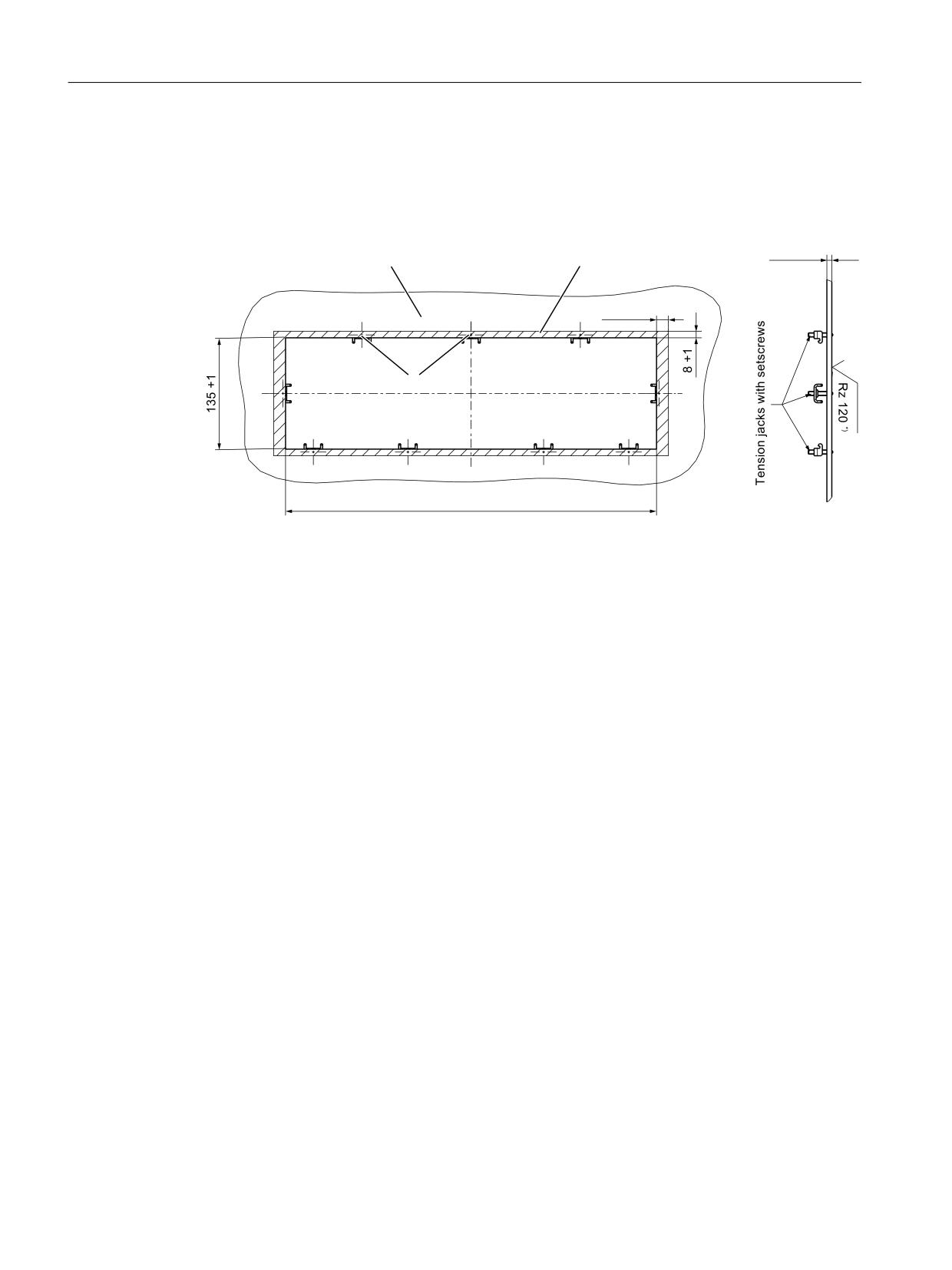
Tension jacks
The machine control panel is mounted from the front in a rectangular cut-out
It is attached using nine tension jacks (0.5 Nm tightening torque), which are included in the
scope of delivery.
0RXQWLQJ SDQHO
6HDOLQJ DUHD
3UHVVXUH SRLQWV
IRU WHQVLRQ MDFNV
,Q WKH VHDOLQJ DUHD
Image 4-9
Panel cutout of MCP 483C PN
Mounting position
Max. 60° to the vertical.
For mounting positions greater than 60°, a fan must also be installed to keep the environmental
temperature of the machine control panel constantly below 55 °C.
4.5
Connecting
Two equivalent connections (Fast Ethernet) are available for Ethernet/PROFINET transfer.
The Ethernet cables are not included in the scope of delivery. They must be ordered separately.
The following components are recommended:
● Ethernet FastConnect cables
● Ethernet FastConnect connectors
More information on this can be found in the SIEMENS IK PI catalog.
Machine control panels
94
Manual, 03/2016, 6FC5397-1AP40-5BA3
Machine control panel: MCP 483C PN
4.6 Maintenance and Service
Securing Ethernet cables
Two cable ties are included in the scope of delivery. These are used to secure the Ethernet
cables on the cover plate at the rear of the machine control panel (see figure in Section: "Control
and display elements" → "Rear side").
NOTICE
Damaged cables caused by chafing edges
Make sure that all cables are routed so that they do not come into contact with chafing edges.
4.6
Maintenance and Service
Cleaning the device
Use a soft cloth moistened either with water or a mild cleaning agent to clean the housing and
operator control elements of the machine control panel.
Checking the device
In order to prevent foreign bodies or liquids entering the machine control panel, regularly check
the device
● that all the housing screws are in place and tight
● for damage to the housing
● for damage to the cable cover or cable entry
Protect the device from environmental effects
Protect the machine control panel against
● direct solar radiation and heat sources
● mechanical vibration and shock
● dust
● moisture, and
● strong magnetic fields
Checking the emergency stop button
Check the emergency stop button regularly to ensure that it functions correctly.
Machine control panels
Manual, 03/2016, 6FC5397-1AP40-5BA3
95
Machine control panel: MCP 483C PN
4.7 Technical data
4.7
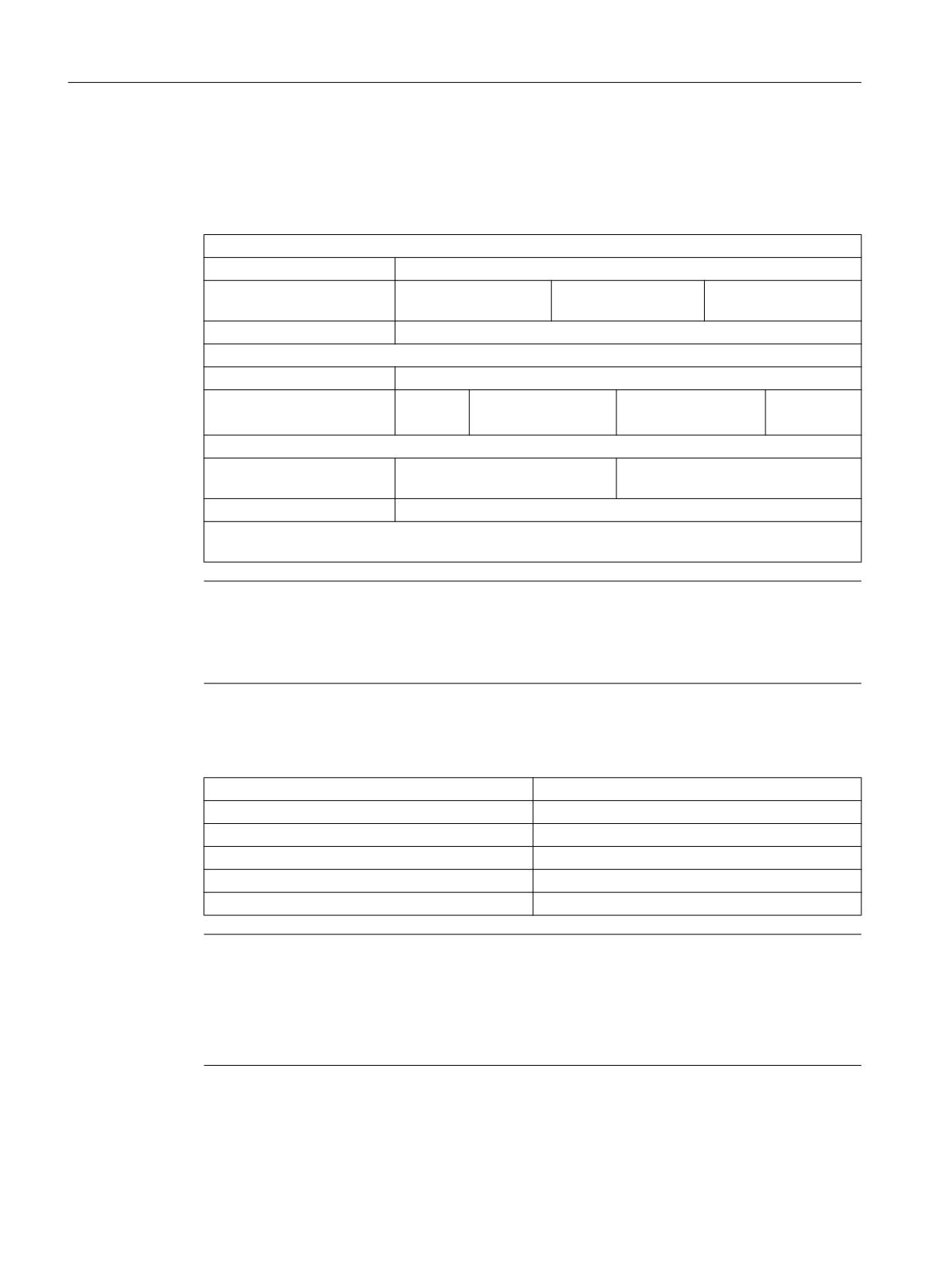
Technical data
MCP 483C PN machine control panel
Safety
Safety class
III; PELV according to EN 50178
Degree of protection accord-
Front side:
Mounting frame:
Rear side:
ing to EN 60529
IP54
IP65
IP00
Approvals
CE / cULus
Electrical data
Input voltage
24 VDC
Power consumption, max.
Board:
Handwheels:
Lamps:
Total:
5 W
2 x 0.9 W
14.4 W (6 x 2.4 W) *)
21.2 W
Mechanical data
Dimensions
Width: 483 mm
Depth: 106 mm
Height: 155 mm
Mounting depth: 54.5 mm
Weight
Approx. 2 kg
*) The outputs for the illuminated pushbuttons (X53/X54) can have a max. permissible current of 0.3 A.
However, the total current consumption of the components must not exceed 1.0 A (24 W).
Note
Information about the climatic and mechanical environmental conditions is contained in the
associated section under:
"General notes and interconnection" → "Operational planning".
Emergency Stop button
Rated voltage
24 VDC
Current magnitude, max.
3 A
Current magnitude, min.
1 mA
Switching capacity
DC 13 according to EN 60947-5-1
Conditional rated short-circuit current
10 A gL/gG according to EN 60947-5-1
B10d
500 000
Note
The quantitative assessment of the emergency stop safety function must be based on the
B10d values corresponding to the used standards (e.g. ISO 13849-1) under consideration of
the respective application (frequency of the actuation, service life, diagnostics by the evaluation
unit, etc.). The B10d values only apply when the technical properties of the emergency stop
button are taken into account.
Machine control panels
96
Manual, 03/2016, 6FC5397-1AP40-5BA3
Machine control panel: MCP 483C PN
4.8 Accessories and spare parts
4.8
Accessories and spare parts
Table 4-4
Accessories and spare parts for machine control panel 483C PN
Name
Description
Quan-
Article number
tity
Emergency Stop but-
22 mm actuating element, 40mm mushroom pushbutton, snap
1
3SB3000-1HA20 *)
ton
action with tamper protection, latching, red, with holder, unlit
Contact block
With two contact pairs (1 NO + 1 NC), 2-pin, screw terminal
1
3SB3400-0A *)
(3rd contact pair can be connected additionally)
Key
Ten key sets, each with three keys for the keyswitch settings
1
6FC5148-0AA03-0AA0
1, 2, 3
Rapid traverse dial
for 16-stage rotary switch MCP 483C
20
6FC5248-0AF30-0AA0
Override spindle / rapid
Electronic rotary switch 1x16G, T=24, cap, button, pointer,
1
6FC5247-0AF12-1AA0
traverse
spindle dials and rapid traverse
Feed / rapid traverse
Electronic rotary switch 1x23G, T=32, cap, button, pointer,
1
6FC5247-0AF13-1AA0
override
feed and rapid-traverse dials
Tension jacks
Set of tensioners for operator components with 2.5 mm profile,
9
6FC5248-0AF14-0AA0
20 mm length
Key covers
Square, can be labeled by laser,
170
6FC5248-0AF12-0AA0
1 set of 90, ergo-gray and 20 each of red / green / yellow /
medium gray
Key covers
Square, for inscription plates,
90
6FC5248-0AF21-0AA0
1 set of 90, clear
Key cover
Square, can be written with laser, one set with 500 items, ergo-
1
6FC5348-0AF00-0AA0
gray (light basic)
Key cover
Square, can be written with laser, one set with 500 items, mid-
1
6FC5348-0AF01-0AA0
gray (light basic)
Cable set
60 cables for additional MCP control devices, 500 mm long
1 set
6FC5247-0AA35-0AA0
Signal cable, hand-
Connecting cable for the handwheel, max. length: 5 m
1
6FX8002-2CP00-1Axy
wheel
xy is the length code:
x (m) = A (0) ...F (5); y (dm) = 0 ... 8
For details, see Image 1-8 Connection cable for COM board
handwheel (Page 28).
*) Safety-related
Accessories pack (for delivery ex works)
9
Key covers for turning (labeled)
Keyset
30
Ergo gray key covers (for labeling)
30
Clear key covers (for labeling)
Machine control panels
Manual, 03/2016, 6FC5397-1AP40-5BA3
97
Machine control panel: MCP 483C PN
4.8 Accessories and spare parts
Machine control panels
98
Manual, 03/2016, 6FC5397-1AP40-5BA3
Machine control panel: MCP 483 PN
5
5.1
Description
Machine control panel MCP 483 PN (PN = PROFINET) enables user-friendly operation of the
machine functions, which are clearly laid out for the user. It is suitable for machine-level
operation of milling and turning machines, and particularly grinding machines.
Note
The IE functionality (IE = Industrial Ethernet) is still included and preset.
Please note the switch position of S2.
46 keys and both control device slots are equipped with user-inscribed slide-in labels for
adapting to specific machines. A DIN A4 film for labeling the slide-in strips is included in the
scope of delivery.
A connecting cable is included in the scope of delivery for connecting the direct keys of the
SINUMERIK OP 012 / OP 015A and TP 015A operator panel fronts.
The machine control panel is secured from the rear using special clamps supplied with the
panel.
Validity
This description applies to the machine control panel:
Type
Key type
Article number
MCP 483 PN
Membrane keys
6FC5303-0AF22-1AA1
The safety-related accessories / spare parts are marked in the "Accessories and spare parts"
section with *).
Features
Control elements:
● Membrane keys
● Operating mode and function keys:
-
50 keys with assigned LEDs, 17 freely assignable customer keys in the standard
assignment
- Direction keys for milling machines with rapid traverse override
● Spindle control with override spindle (rotary switch with 16 positions)
● Feed control with override feed / rapid traverse (rotary switch with 23 positions)
Machine control panels
Manual, 03/2016, 6FC5397-1AP40-5BA3
99
Machine control panel: MCP 483 PN
5.1 Description
● Keyswitch (four positions and three different keys)
● Emergency Stop button, two contact blocks (1 NO + 1 NC)
Interfaces:
● Ethernet (transfer rate: 10/100 Mbit/s; for IE and PN)
● Nine customer-specific inputs (e.g. for illuminated pushbuttons)
● Six customer-specific outputs
● For 16 direct keys of OP 012 / OP 015A / TP 015A (connection cable: 850 mm, included
in scope of delivery)
● Connection for two handwheels (Sub-D)
(velocity input and contour handwheel are only possible if connecting through the
handwheel connection module 6FC5303-0AA02-0AA0 or the MCP PN interface
6FC5303-0AF03-0AA0)
Expansion slots:
Two slots for control devices (d = 16 mm).
(additional cable set required for control devices, see Table 5-4 Accessories and spare parts
for machine control panel 483 PN (Page 112))
Machine control panels
100
Manual, 03/2016, 6FC5397-1AP40-5BA3
Machine control panel: MCP 483 PN
5.2 Operator controls and indicators
5.2
Operator controls and indicators
5.2.1
Front side
Overview
(1)
Emergency stop button
(2)
Slots for control devices (d = 16 mm)
(3)
Reset button
(4)
Program control
(5)
Operating modes, machine functions
(6)
User keys T1 to T15
(7)
Direction keys with rapid traverse override (R1 to R15)
(8)
Spindle control with override switch
(9)
Feed control with override switch
(10)
Key-operated switch (four positions)
Image 5-1
Position of control elements on MCP 483 PN
Machine control panels
Manual, 03/2016, 6FC5397-1AP40-5BA3
101
Machine control panel: MCP 483 PN
5.2 Operator controls and indicators
Emergency stop button
Emergency stop button
Press the red emergency stop button in emergencies if
∎ people are at risk,
∎ there is the danger of machines or the workpiece being damaged.
As a rule, when operating the Emergency Stop button, all drives are brought
to a standstill with max. braking torque.
Turn the Emergency Stop button counterclockwise to unlatch it.
Machine manufacturer
For other reactions to the emergency stop:
Refer to the machine tool manufacturer's instructions
WARNING
Danger of death resulting from the premature emergency stop unlocking
If you have shut down the system to be monitored, you can only release the emergency stop
button or put the system to be monitored back into operation if the condition that triggered
the emergency stop function has been corrected and a safe restart is carried out.
Emergency stop circuit
(0(5*(1&<
6723
Image 5-2
Emergency stop circuit
Slots for control devices
NOTICE
Damage to the front
Do not knock out the openings for mounting control devices (2) in "Position of control elements
on MCP 483 PN", but drill them to the required width.
Machine control panels
102
Manual, 03/2016, 6FC5397-1AP40-5BA3
Machine control panel: MCP 483 PN
5.2 Operator controls and indicators
Information for the installation, or to select control devices, please refer to the following
Section: Front side (Page 31).
5.2.2
Rear side
Rear
① Ground terminal
② Feedrate override
X30
③ Spindle override
X31
④ Power supply interface
X10
⑤ Switch S1 *)
⑥ Handwheel connection
X60
⑦ Handwheel connection
X61
⑧ Emergency Stop
⑨ Installation locations for additional control devices (d = 16 mm)
⑩ Ethernet connection, port 1
X20
⑪ Ethernet connection, port 2
X21
⑫ Ethernet cable strain relief
⑬ Interface for the connection of the keyswitch
⑭ LEDs *)
⑮ Switch S2 *)
⑯ Customer-specific inputs and outputs *)
*) Detailed figure under "Interfaces" → "Description"
Image 5-3
Rear of the MCP 483 PN with Ethernet connecting cables
Machine control panels
Manual, 03/2016, 6FC5397-1AP40-5BA3
103
Machine control panel: MCP 483 PN
5.3 interfaces
Image 5-4
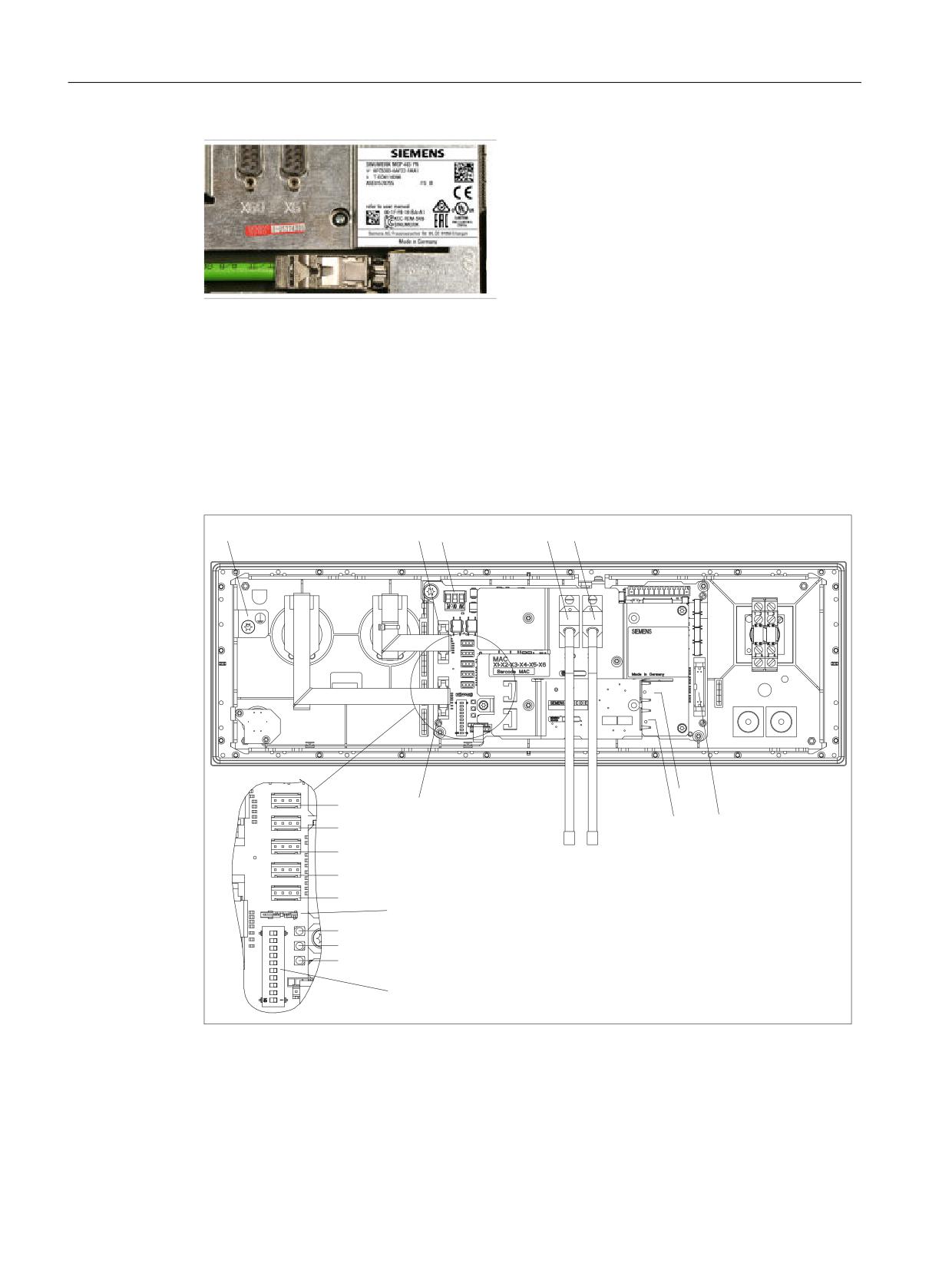
MCP 483 PN - MAC address/rating plate
5.3
interfaces
5.3.1
Overview
;
;
;
;
;
;
;
;
;
;
;
;
;
6
+
+
+
6
Image 5-5
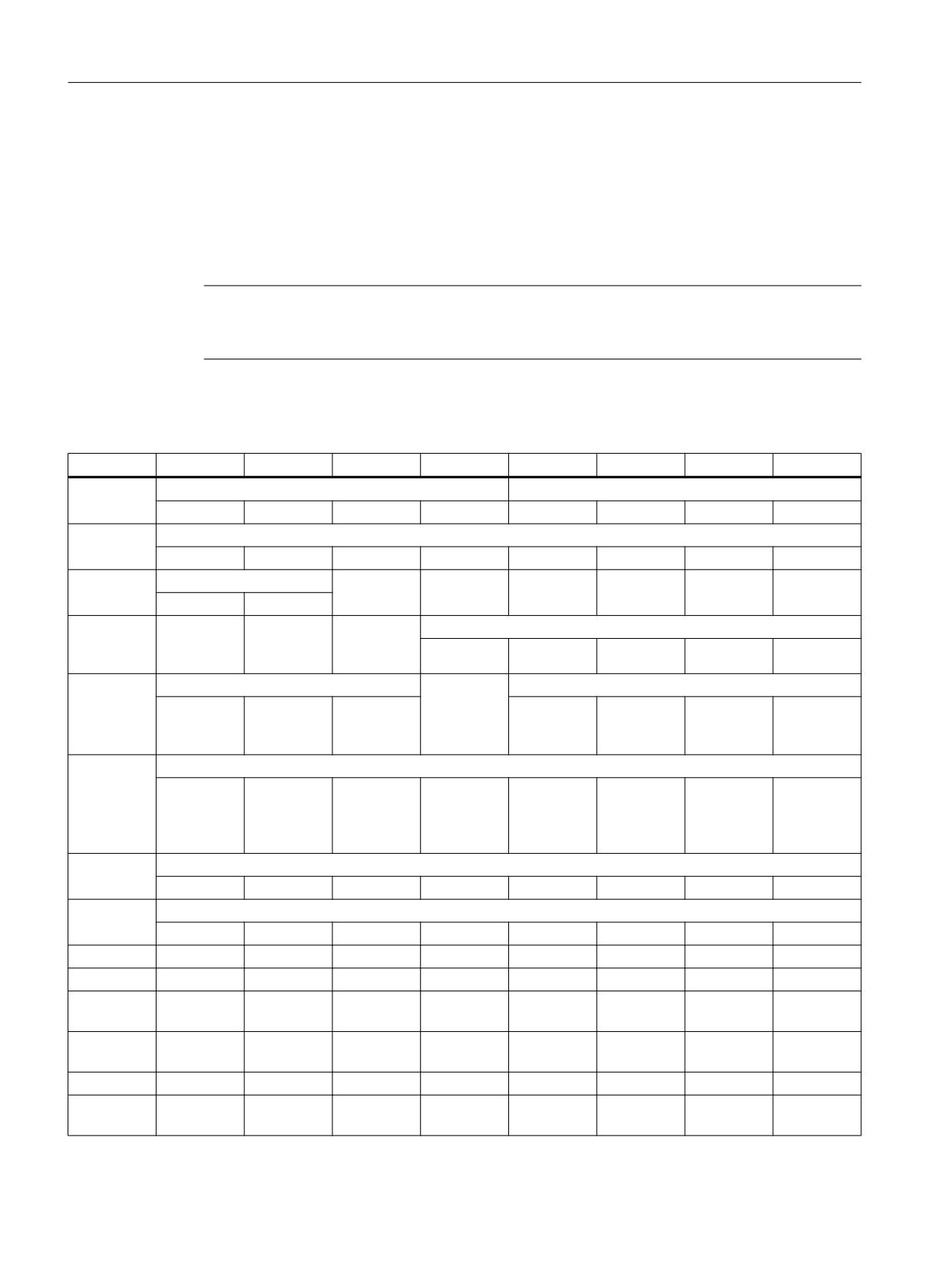
Rear of the MCP 483 PN with interfaces
(1)
Equipotential bonding
X10
Power supply interface
Machine control panels
104
Manual, 03/2016, 6FC5397-1AP40-5BA3
Machine control panel: MCP 483 PN
5.3 interfaces
X20
Ethernet port 1
X21
Ethernet port 2
X30
Interface for rotary switch feed override
X31
Interface for rotary switch spindle override
X51 / X52 / X55
Interfaces for customer-specific inputs
X53 / X54
Interfaces for customer-specific outputs
X60 / X61
Connections for 2 handwheels (TTL / differential - can be set with switch S1)
X70
Interface for connecting 16 direct keys
S1
Switch for setting the handwheel signal type
S2
Switch for setting the MCP address
LEDs
H1
POWER OK (green)
H2
BUSSYNC
H3
BUSFAULT
Equipotential bonding
The equipotential bonding conductor is attached by means of an M5 screw.
5.3.2
Description
Pin assignment
For more detailed information, see "General information and networking", Chapter:
"Connecting".
Switch S1/S2
Settings, see Chapter "Machine control panel: MCP 310C PN", Section "Interfaces".
Machine control panels
Manual, 03/2016, 6FC5397-1AP40-5BA3
105
Machine control panel: MCP 483 PN
5.3 interfaces
5.3.3
Input / output images
Standard + two handwheels
The specifications for assigning input and output bytes listed in the tables can be changed in
the PLC via parameter assignment.
Note
The following applies in respect of the process input and output images in the tables: n is
defined by means of FB1 parameters in OB100 of the PLC.
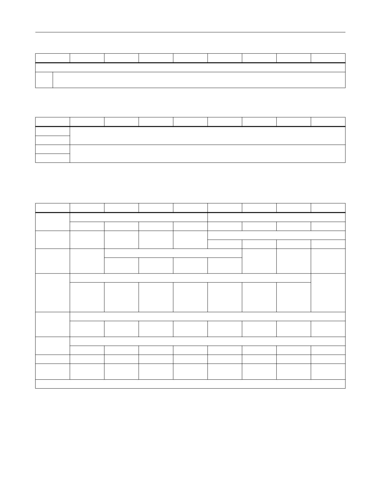
Table 5-1
Process input image for MCP 483 PN
Byte
Bit7
Bit6
Bit5
Bit4
Bit3
Bit2
Bit1
Bit0
EB n + 0
Spindle override
Mode
D (23)
C (22)
B (21)
A (20)
JOG
TEACH IN
MDA
AUTO
EB n + 1
Machine function
REPOS
REF.
var. INC
10000 INC
1000 INC
100 INC
10 INC
1 INC
EB n + 2
Key-operated switch
Spindle
*Spindle
Feed
*Feed
NC
*NC
start
stop
start
stop
start
stop
Position 0
Position 2
EB n + 3
RESET
Keyswitch
Single
Feedrate override
block
E (24)
D (23)
C (22)
B (21)
A (20)
position 1
EB n + 4
Arrow keys
Keyswitch
Axis selection
+
-
Rapid tra-
X
4. axis
7. axis
position 3
R15
R13
verse
R1
R4
R7
R10
R14
EB n + 5
Axis selection
Y
Z
5. axis
Traversing
9. axis
8. axis
6. axis
R2
R3
R5
command
R11
R9
R8
R6
in
MCS/WCS
EB n + 6
Freely assignable customer keys
T9
T10
T11
T12
T13
T14
T15
-
Freely assignable customer keys
EB n + 7
T1
T2
T3
T4
T5
T6
T7
T8
EB n + 8
DT8
DT7
DT6
DT5
DT4
DT3
DT2
DT1
EB n + 9
DT16
DT15
DT14
DT13
DT12
DT11
DT10
DT9
EB n + 10
KT-IN8
KT-IN7
KT-IN6
KT-IN5
KT-IN4
KT-IN3
KT-IN2
KT-IN1
X55.2
X55.1
X52.3
X52.2
X52.1
X51.3
X51.2
X51.1
EB n + 11
-
-
-
-
-
-
-
KT-IN9
X55.3
EB n + 12
-
-
-
-
-
-
-
-
EB n + 13
-
-
-
X31
X31
X31
X31
X31
pin 6 1)
pin 7 1)
pin 8 1)
pin 9 1)
pin 10 1)
Machine control panels
106
Manual, 03/2016, 6FC5397-1AP40-5BA3
Machine control panel: MCP 483 PN
5.3 interfaces
Byte
Bit7
Bit6
Bit5
Bit4
Bit3
Bit2
Bit1
Bit0
Signals marked with * are inverse signals.
1)
If the 4-stage rotary spindle override switch on X31 is replaced by a 5-stage rotary switch, the input information here
can be measured in 5 stages.
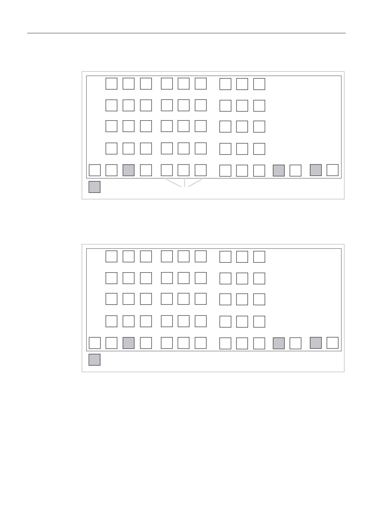
Table 5-2
Input image for handwheel data
Byte
Bit7
Bit6
Bit5
Bit4
Bit3
Bit2
Bit1
Bit0
EB n + 14
Handwheel 1 counter status
(16-bit signed, low-order byte equals byte n+14)
EB n + 15
EB n + 16
Handwheel 2 counter status
(16-bit signed, low-order byte equals byte n+16)
EB n + 17
Within the SINUMERIK control, the handwheel data is processed directly by the NCK and is
not available to the PLC.
Table 5-3
Process output image for MCP 483 PN
Byte
Bit7
Bit6
Bit5
Bit4
Bit3
Bit2
Bit1
Bit0
AB n + 0
Machine function
Mode
1000 INC
100 INC
10 INC
1 INC
JOG
TEACH IN
MDA
AUTO
AB n + 1
Feed
*Feed
NC
*NC
Machine function
start
stop
start
stop
REPOS
REF.
var. INC
10000 INC
AB n + 2
Direction
Axis selection
Single
Spindle
*Spindle
key -
block
start
stop
X
4. axis
7. axis
R13
R1
R4
R7
R10
AB n + 3
Axis selection
Direction
key +
Z
5. axis
Traversing
9. axis
8. axis
6. axis
R3
R5
command
R11
R9
R8
R6
R15
in
MCS/WCS
AB n + 4
Freely assignable customer keys
T9
T10
T11
T12
T13
T14
T15
Y
R2
AB n + 5
Freely assignable customer keys
T1
T2
T3
T4
T5
T6
T7
T8
AB n + 6
-
-
-
-
-
-
RESET
R14
AB n + 7
-
-
KT-OUT6
KT-OUT5
KT-OUT4
KT-OUT3
KT-OUT2
KT-OUT1
X54.3
X54.2
X54.1
X53.3
X53.2
X53.1
Signals marked with * are inverse signals
Machine control panels
Manual, 03/2016, 6FC5397-1AP40-5BA3
107
Machine control panel: MCP 483 PN
5.3 interfaces
Default key assignment
-2*
REP
REF
(T1)
(T2)
(T3)
X
Y
Z
(R1)
(R2)
(R3)
TCH
INC
INC
(T4)
(T5)
(T6)
4
5
6
VAR
1
(R4)
(R5)
(R6)
MDA
INC
INC
(T7)
(T8)
(T9)
7
8
9
10
100
(R7)
(R8)
(R9)
AUT
INC
INC
(T10)
(T11)
(T12)
WKS
1000
10000
(R10)
(R11)
(R12)
RESET
Einzel-
NC-
NC-
(T13)
(T14)
(T15)
-
Eilg.
+
Sp.-
Sp.-
VS-
VS-
satz
STOP
START
(R13)
(R14)
(R15)
STOP
START
STOP
START
(LQJ¦QJH LQYHUV
7
7
QLFKW EHVFKULIWHWH 7DVWHQ
Image 5-6
Default key assignment of MCP 483 PN
Assignment of the inputs (I) and outputs (O) to the keys and LEDs
(
(
(
(
(
(
(
(
(
$
$
$
$
$
$
$
$
$
(
(
(
(
(
(
(
(
(
$
$
$
$
$
$
$
$
$
(
(
(
(
(
(
(
(
(
$
$
$
$
$
$
$
$
$
(
(
(
(
(
(
(
(
(
$
$
$
$
$
$
$
$
$
(
(
(
(
(
(
(
(
(
(
(
(
(
(
$
$
$
$
$
$
$
$
$
$
$
$
$
$
(LQJ¦QJH LQYHUV
Image 5-7
Inputs and outputs of the MCP 483 PN keyboard
Machine control panels
108
Manual, 03/2016, 6FC5397-1AP40-5BA3
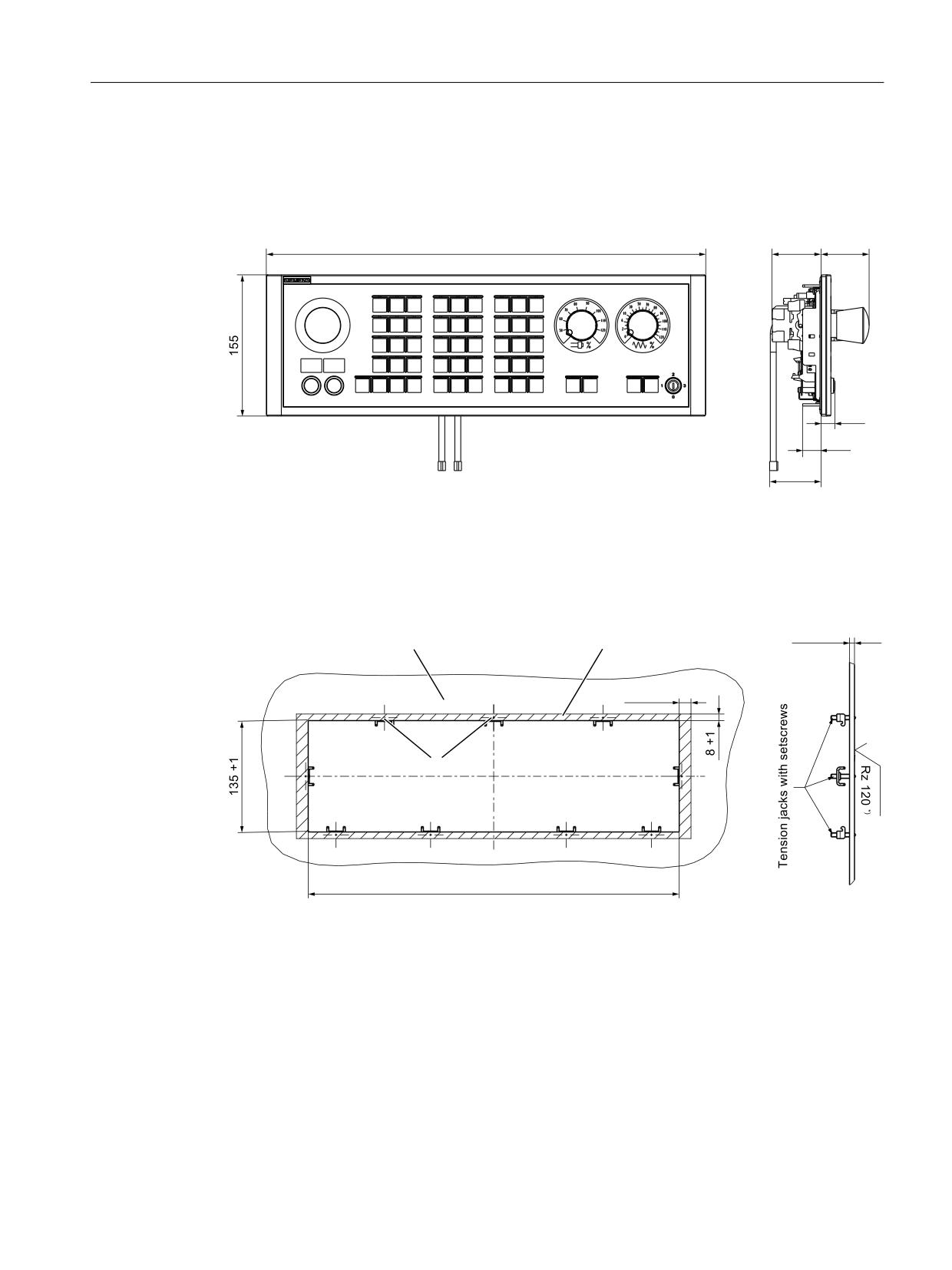
Machine control panel: MCP 483 PN
5.4 Mounting
5.4
Mounting
Dimension drawing
Image 5-8
Dimension drawing of machine control panel MCP 483 PN
Tension jacks
The machine control panel is attached using 9 tension jacks (tightening torque, 0.8 Nm).
0RXQWLQJ SDQHO
6HDOLQJ DUHD
3UHVVXUH SRLQWV
IRU WHQVLRQ MDFNV
,Q WKH VHDOLQJ DUHD
Image 5-9
Panel cutout of MCP 483 PN
Mounting position
Max. 60° to the vertical. For mounting positions greater than 60°, a fan must also be installed
to keep the ambient temperature of the machine control panel constantly below 55 °C.
Machine control panels
Manual, 03/2016, 6FC5397-1AP40-5BA3
109
Machine control panel: MCP 483 PN
5.6 Maintenance and Service
5.5
Connecting
Two equivalent connections (Fast Ethernet) are available for Ethernet/PROFINET transfer.
The Ethernet cables are not included in the scope of delivery. They must be ordered separately.
The following components are recommended:
● Ethernet FastConnect cables
● Ethernet FastConnect connectors
More information on this can be found in the SIEMENS IK PI catalog.
Securing Ethernet cables
Two cable ties are included in the scope of delivery. These are used to secure the Ethernet
cables on the cover plate at the rear of the machine control panel (see figure in Section: "Control
and display elements" → "Rear side").
NOTICE
Damaged cables caused by chafing edges
Make sure that all cables are routed so that they do not come into contact with chafing edges.
5.6
Maintenance and Service
Cleaning the device
Use a soft cloth moistened either with water or a mild cleaning agent to clean the housing and
operator control elements of the machine control panel.
Checking the device
In order to prevent foreign bodies or liquids entering the machine control panel, regularly check
the device
● that all the housing screws are in place and tight
● for damage to the housing
● for damage to the cable cover or cable entry
Protect the device from environmental effects
Protect the machine control panel against
● direct solar radiation and heat sources
● mechanical vibration and shock
● dust
Machine control panels
110
Manual, 03/2016, 6FC5397-1AP40-5BA3
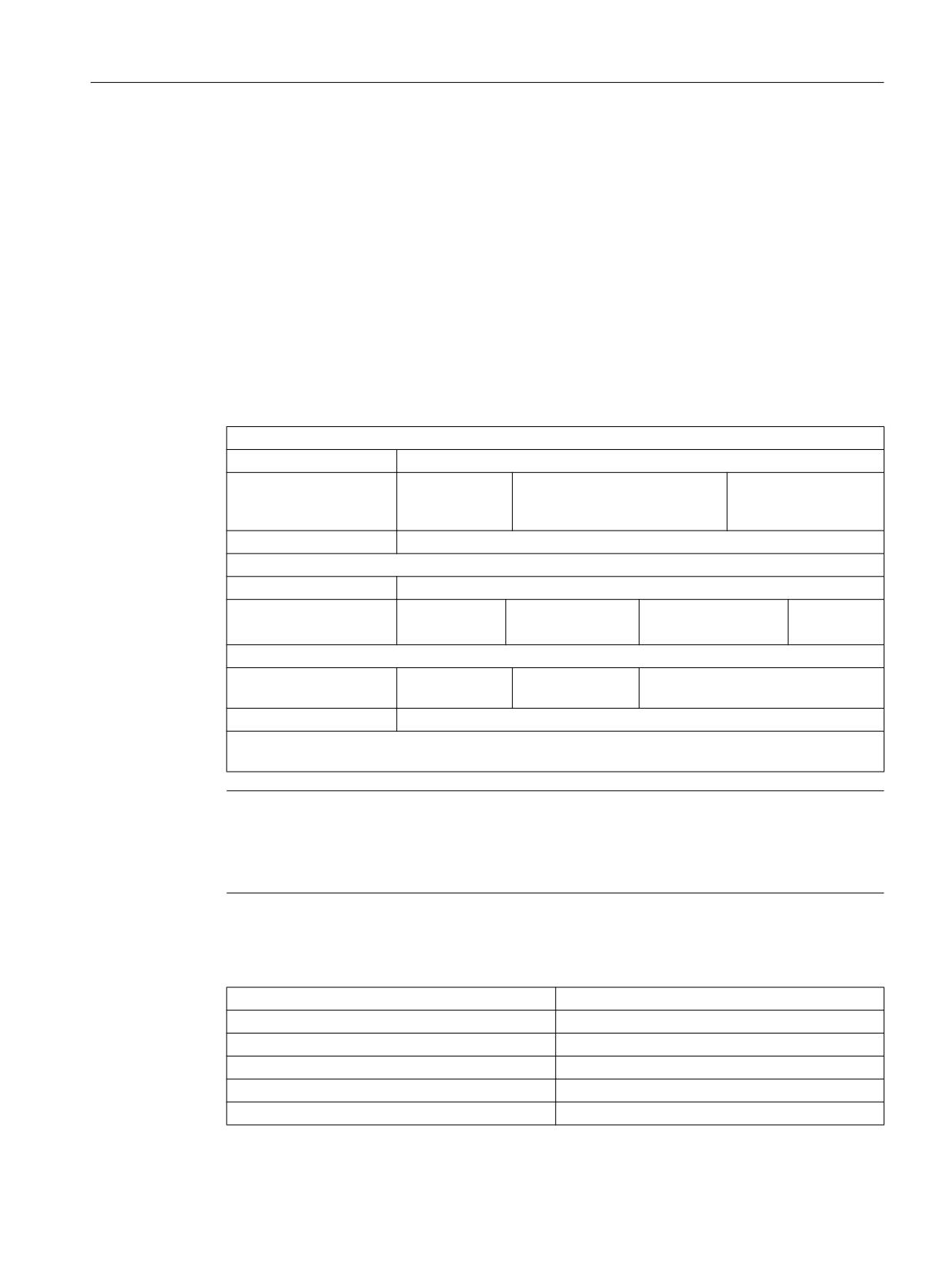
Machine control panel: MCP 483 PN
5.7 Technical data
● moisture, and
● strong magnetic fields
Checking the emergency stop button
Check the emergency stop button regularly to ensure that it functions correctly.
5.7
Technical data
Machine control panel MCP 483 PN
Safety
Safety class
III; PELV according to EN 50178
Degree of protection ac-
Front side:
Mounting frame:
Rear side:
cording to
IP54
IP65
IP00
DIN IEC 529
Approvals
CE / cULus
Electrical data
Input voltage
24 VDC
Power consumption,
Board:
Handwheels:
Lamps:
Total:
max.
5 W
2 x 0.9 W
14.4 W (6 x 2.4 W) *)
21.2 W
Mechanical data
Dimensions
Width: 483 mm
Height: 155 mm
Depth: 106.7 mm
Mounting depth: 53.9 mm
Weight
Approx. 1.6 kg
*) The outputs for the illuminated pushbuttons (X53/X54) can have a max. permissible current of 0.3 A.
However, the total current consumption of the components must not exceed 1.0 A (24 W).
Note
Information about the climatic and mechanical environmental conditions is contained in the
associated section under:
"General notes and interconnection" → "Operational planning".
Emergency Stop button
Rated voltage
24 VDC
Current magnitude, max.
3 A
Current magnitude, min.
1 mA
Switching capacity
DC 13 according to EN 60947-5-1
Conditional rated short-circuit current
10 A gL/gG according to EN 60947-5-1
B10d
500 000
Machine control panels
Manual, 03/2016, 6FC5397-1AP40-5BA3
111
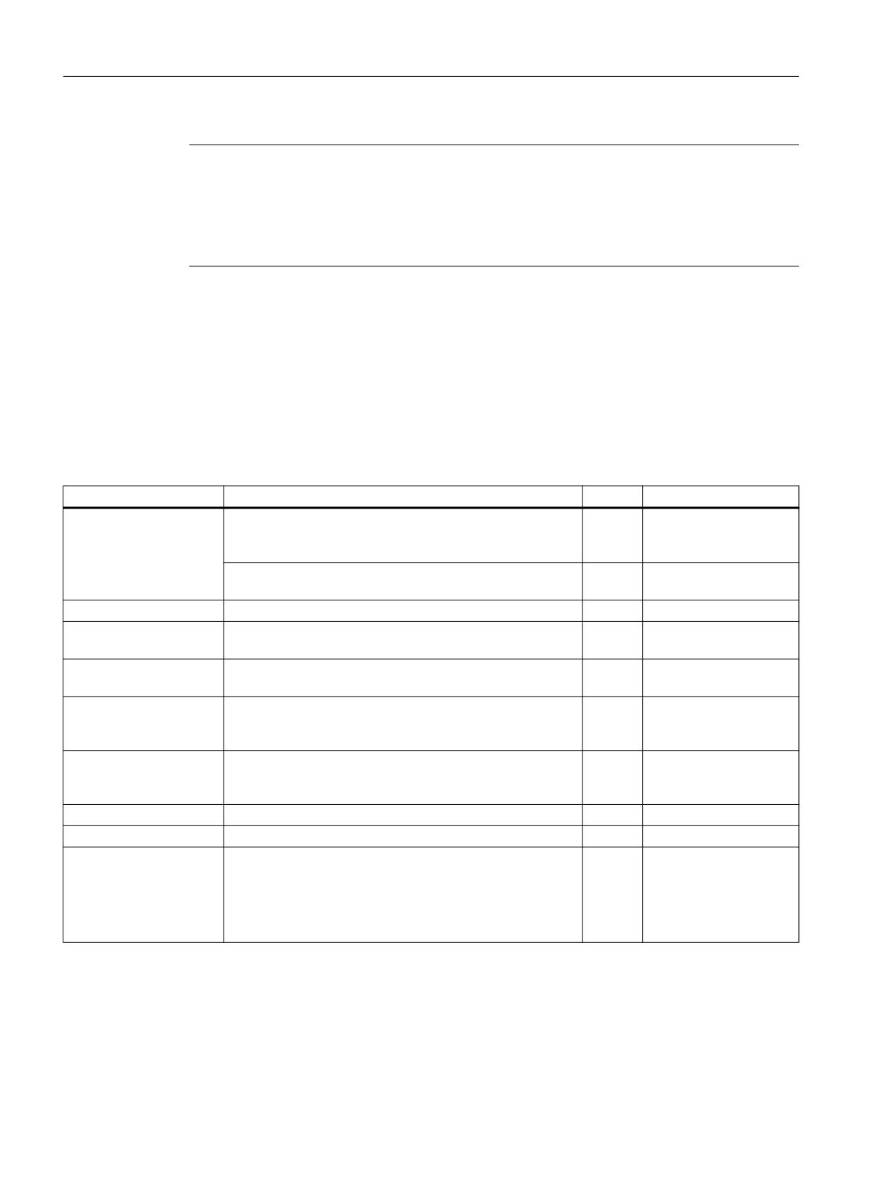
Machine control panel: MCP 483 PN
5.8 Accessories and spare parts
Note
The quantitative assessment of the emergency stop safety function must be based on the
B10d values corresponding to the used standards (e.g. ISO 13849-1) under consideration of
the respective application (frequency of the actuation, service life, diagnostics by the evaluation
unit, etc.). The B10d values only apply when the technical properties of the emergency stop
button are taken into account.
5.8
Accessories and spare parts
5.8.1
Overview
Table 5-4
Accessories and spare parts for machine control panel 483 PN
Name
Description
Number
Article number
22 mm actuating element, 40 mm mushroom pushbutton,
1
3SB3000-1HA20 *)
snap action with tamper protection, latching, red, with hold-
Emergency Stop button
er, unlit
Contact block with 2 contacts, 1 NO + 1 NC, 2-pole ,screw
1
3SB3400-0A *)
terminal
Keyswitch
Keyswitch with key
1
6FC5247-0AF02-0AA0
Sets of keys
Ten key sets, each with three keys for the keyswitch settings
1 set
6FC5148-0AA03-0AA0
1, 2, 3
Set of tension jacks
Tension jack set (9 items) for supplementary components
1 set
6FC5248-0AF14-0AA0
with 2.5 mm profile, length: 20 mm
Override, spindle
Override spindle / rapid traverse, electronic rotary switch
1
6FC5247-0AF12-1AA0
rotary switch
1x16G, T=24, cap, button, pointer, spindle dials and rapid
traverse
Override, feed
Feed / rapid traverse override, electronic rotary switch
1
6FC5247-0AF13-1AA0
rotary switch
1x23G, T=32, cap, button, pointer, feed and rapid-traverse
dials
Slide-in labels
Slide-in label, (3 films, A4)
1 set
6FC5248-0AF22-1AA1
Cable set
60 cables for additional MCP control devices, 500 mm long
1 set
6FC5247-0AA35-0AA0
Signal cable, handwheel
Connecting cable for the handwheel, max. length: 5 m
1
6FX8002-2CP00-1Axy
xy is the length code:
x (m) = A (0) ...F (5); y (dm) = 0 ... 8
For details, see Image 1-8 Connection cable for COM board
handwheel (Page 28).
*) Safety-related
Machine control panels
112
Manual, 03/2016, 6FC5397-1AP40-5BA3
Machine control panel: MCP 483 PN
5.8 Accessories and spare parts
5.8.2
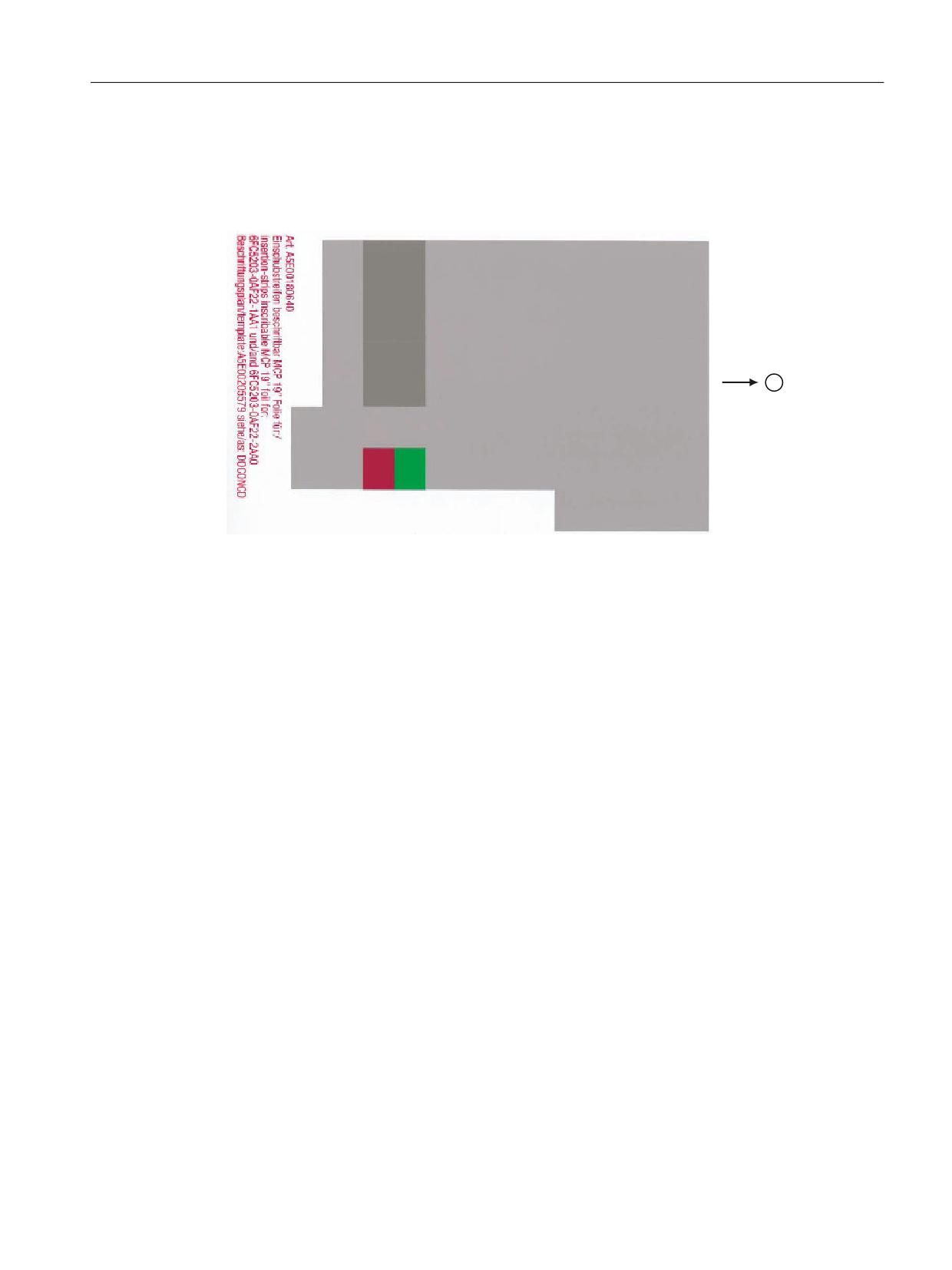
Membrane keyboard: Labeling the slide-in labels
You can create your own slide-in labels to label the keys differently. Use the blank films that
can be printed for this purpose.
Image 5-10 Blank film for MCP 483 PN
Preparing slide-in labels
Instructions are given below on how to print the required key symbols on the supplied film or
how to create your own individual film:
The DOConCD or CD included in Catalog NC 61/ NC 62 includes four files for printing the
blank films:
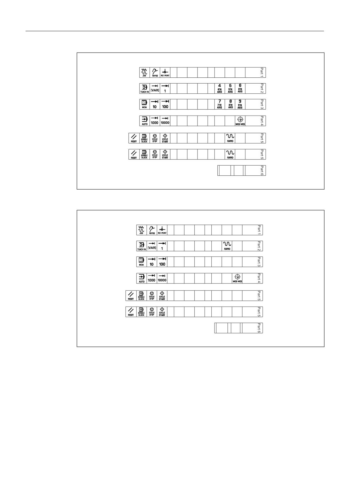
● Template_M_MCP483.doc [default assignment for milling - standard; (A)]
● Template_T_MCP483.doc [defaults for turning; (B)]
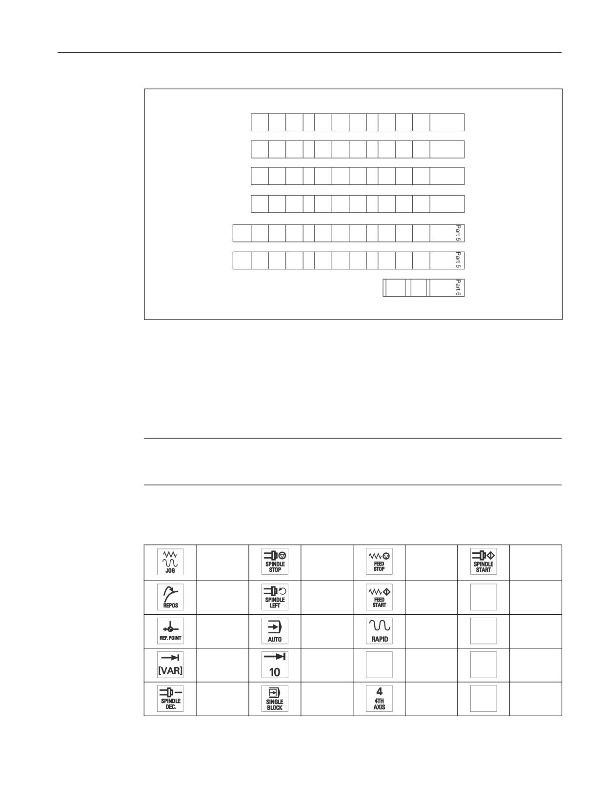
● Template_MCP483.doc [blank template for film: Item No. A5E00205579; (C)]
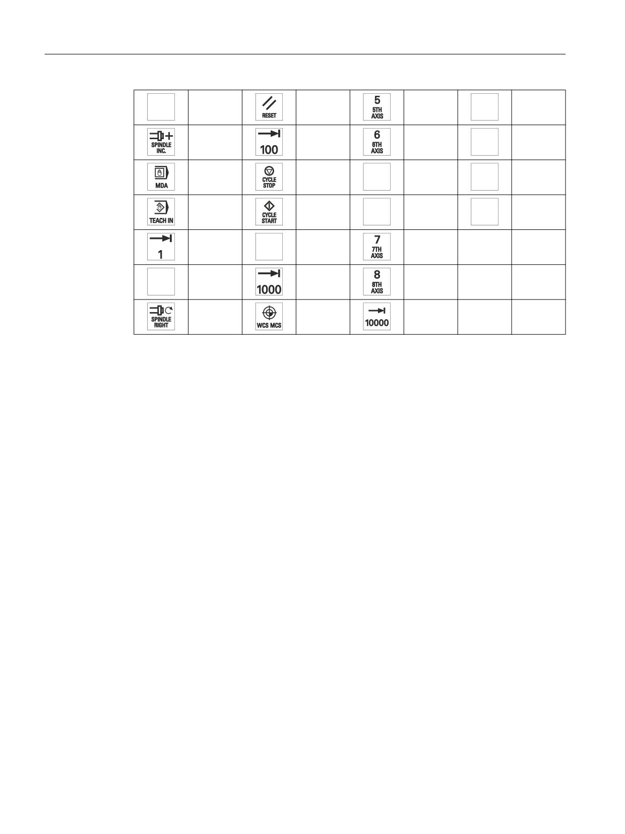
● Symbols.doc Key symbols as Word file, inscription on labels as jpg file (D)
Files Template_M_MCP483.doc, Template_T_MCP483.doc and Template_MCP483.doc
include a table function showing the corresponding keyboard positions.
An example of each of the MCP files (milling and turning) is given below:
Machine control panels
Manual, 03/2016, 6FC5397-1AP40-5BA3
113
Machine control panel: MCP 483 PN
5.8 Accessories and spare parts
;
<
=
Image 5-11 Template_M_MCP483.doc for the "Milling" version (A)
<
;
&
=
=
&
;
<
Image 5-12 Template_T_MCP483.doc for the "Turning" version (B)
Machine control panels
114
Manual, 03/2016, 6FC5397-1AP40-5BA3
Machine control panel: MCP 483 PN
5.8 Accessories and spare parts
Image 5-13 Template_MCP483.doc (blank template for film: Item No. A5E00205579 (C)
Within the table cells the key symbol required in each case can be copied and pasted into the
corresponding table field.
The vertical bars shown in the diagram do not appear on the printed-out labels.
The strip "Part5" is included twice so that it is available optionally as either a 1-color or 3-color
strip.
Note
Use the "Arial" font to format text. This font is comparable to the "Univers S57" font used by
Siemens for the key labeling.
Table 5-5
Symbols.doc file (D)
7001
7013
7025
7124
7002
7014
7026
7125
&
7003
7015
7027
7126
;
7004
7016
7028
7127
=
<
7005
7017
7029
7128
=
Machine control panels
Manual, 03/2016, 6FC5397-1AP40-5BA3
115
Machine control panel: MCP 483 PN
5.8 Accessories and spare parts
7006
7018
7030
7129
;
7007
7019
7031
7130
<
7008
7020
7032
7131
=
7009
7021
7033
7132
&
7010
7022
7120
<
7011
7023
7121
;
7012
7024
7123
Creating your own symbols
● Printing in a vector program (e.g. Designer, Freehand, CorelDraw):
- Draw a 15 x 15 mm square, fill with the color white and give it an invisible border line.
- Place the symbol in the center of this square.
- Copy the entire image (square and symbol) and paste it into a Word document
(Symbols.doc).
● Drawing in an image editing program (e.g. Photoshop, Picture Publisher, Paint):
- Create a square area (e.g. 100 x 100 pixels) filled with the color white.
- Draw the symbol in the center of this square.
- Copy the entire image (square and symbol) and paste it into the Word document
(Symbols.doc).
Machine control panels
116
Manual, 03/2016, 6FC5397-1AP40-5BA3
Machine control panel: MCP 483 PN
5.8 Accessories and spare parts
Dimension drawings
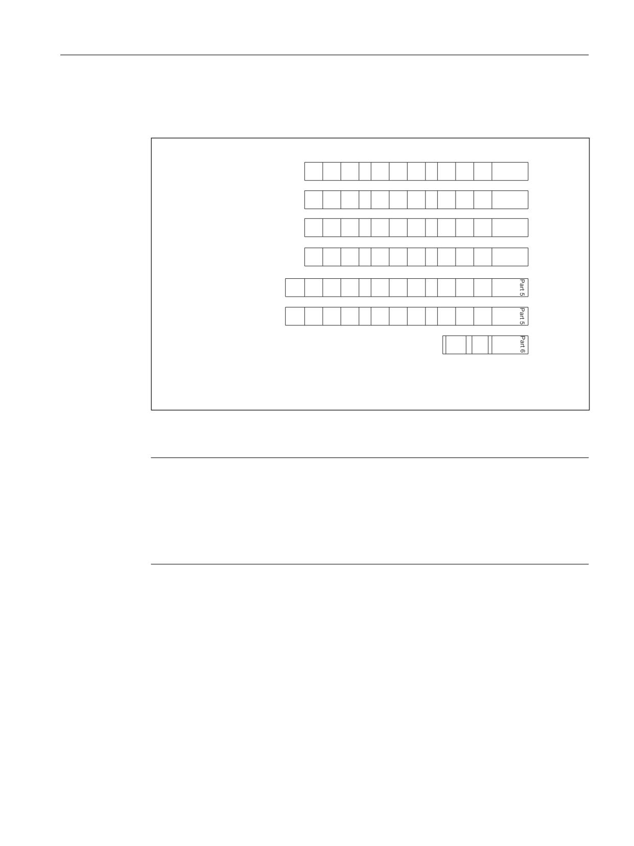
The following is a dimension drawing for the MCP 483 PN blank template:
1DUURZ ODEHO ZLGWK
FP KHLJKW
FP
+HLJKW
FP
+HLJKW
FP
+HLJKW
FP
+HLJKW
FP
1DUURZ ODEHO ZLGWK
FP KHLJKW
FP
+HLJKW
FP
+HLJKW
FP
+HLJKW
FP
:LGWK
FP
:LGWK FP
:LGWK
FP
:LGWK
FP
:LGWK
FP
Image 5-14 Dimension drawing for MCP 483 PN slide-in labels
Note
The slide-in strips are printed on the front with a laser printer. HP Color Laser Jet film C2936A
is used.
To make the labels easier to slide in, they should be rounded by about 1.5 mm.
The outer lines of the strip are the cutting edge.
It is advisable to run a test print on normal paper before printing the labels on film.
Machine control panels
Manual, 03/2016, 6FC5397-1AP40-5BA3
117
Machine control panel: MCP 483 PN
5.8 Accessories and spare parts
Machine control panels
118
Manual, 03/2016, 6FC5397-1AP40-5BA3
Machine control panel: MCP 483
6
6.1
Description
The machine control panel MCP 483 permits user-friendly and clear operation of the machine
functions. It is suitable for machine-level operation of milling and turning machines, and
particularly grinding machines.
46 keys and both control device slots are equipped with user-inscribed slide-in labels for
adapting to specific machines. A DIN A4 film for labeling the slide-in strips is included in the
delivery kit.
A connecting cable is included in the scope of delivery for connecting the direct keys of the
SINUMERIK OP 012 / OP 015A and TP 015A operator panel fronts.
The machine control panel is secured from the rear using special clamps supplied with the
panel.
Validity
The description applies to the MCP 483 machine control panel.
Article number 6FC5203-0AF22-1AA2.
The safety-related accessories / spare parts are marked in the "Accessories and spare parts"
section with *).
Features
Control elements:
● Membrane keys
● Operating mode and function keys:
-
50 keys with LEDs, 17 freely assignable customer keys in the standard assignment
– Direction keys for milling machines with rapid traverse override
● Spindle control with override spindle (rotary switch with 16 positions)
● Feed control with override feed / rapid traverse (rotary switch with 23 positions)
● Keyswitch (four positions and three different keys)
● Emergency stop button, two contact blocks (1 NO + 1 NC)
Interfaces:
● PROFIBUS DP
● Six customer-specific input/outputs
(Additional cable set required for the control devices, see Section: "Accessories and spare
parts".)
Machine control panels
Manual, 03/2016, 6FC5397-1AP40-5BA3
119
Machine control panel: MCP 483
6.2 Operating and display elements
● For 16 direct keys of OP 012 / OP 015A / TP 015A
(connection cable: 850 mm, included in scope of delivery)
● For two handwheels (max. cable length: 5 m)
Expansion slots:
Two slots for control devices (d = 16 mm)
6.2
Operating and display elements
6.2.1
Front side
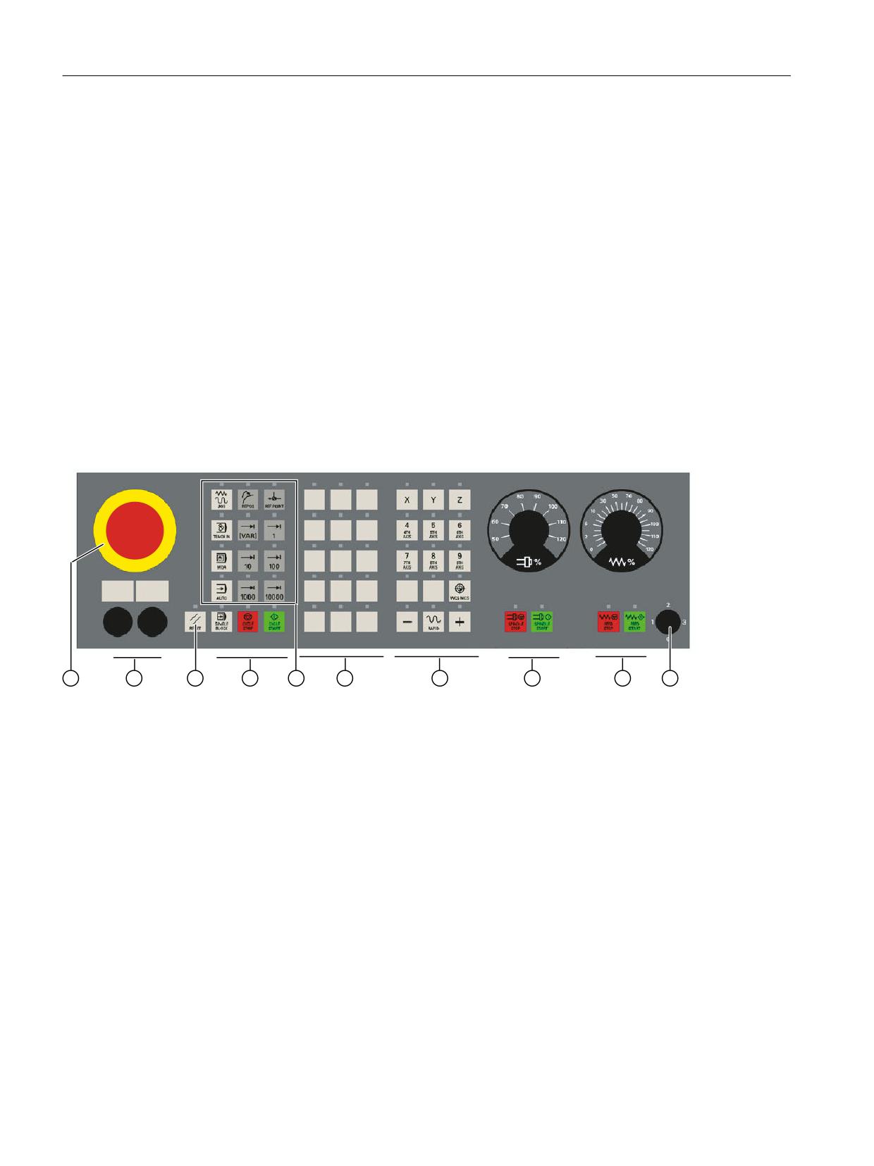
Overview
① Emergency Stop button
② Slots for control devices (d = 16 mm)
③ Reset button
④ Program control
⑤ Operating modes, machine functions
⑥ User keys (T1 to T15)
⑦ Direction keys with rapid traverse override (R1 to R15)
⑧ Spindle control with rotary override switch
⑨ Feed control with rotary override switch
⑩ Key-operated switch (four positions)
Image 6-1
Position of control elements on MCP 483 (milling version)
Machine control panels
120
Manual, 03/2016, 6FC5397-1AP40-5BA3
Machine control panel: MCP 483
6.2 Operating and display elements
Emergency Stop button
Emergency Stop button
Press the red Emergency Stop button in emergencies if
∎ when a person is at risk,
∎ when there is danger of the machine or workpiece being damaged.
As a rule, when operating the Emergency Stop button, all drives are brought to a
standstill with max. braking torque.
Turn the Emergency Stop button counterclockwise to unlatch it.
For other responses to an Emergency Stop:
refer to the machine tool manufacturer's instructions!
WARNING
Danger of death resulting from the premature emergency stop unlocking
If you have shut down the system to be monitored, you can only release the emergency stop
button or put the system to be monitored back into operation if the condition that triggered
the emergency stop function has been corrected and a safe restart is carried out.
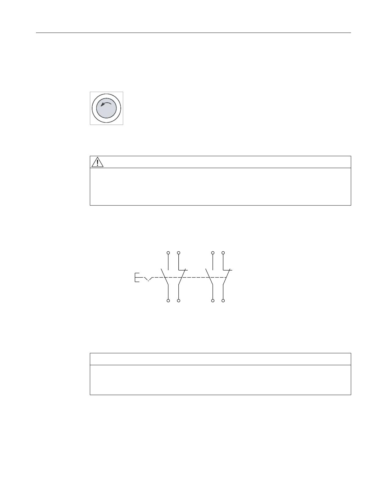
Circuit for emergency stop button
(PHUJHQF\ 6WRS
EXWWRQ
Image 6-2
Emergency Stop button screw-type terminal diagram
Slots for control devices
NOTICE
Damage to the front
The openings for mounting control devices (2) in Fig.: "Position of control elements of machine
control panel MCP 483" must not be knocked out, but drilled to the required width.
Information for the installation, or to select control devices, please refer to the following Section:
Front side (Page 31).
Machine control panels
Manual, 03/2016, 6FC5397-1AP40-5BA3
121
Machine control panel: MCP 483
6.2 Operating and display elements
6.2.2
Rear side
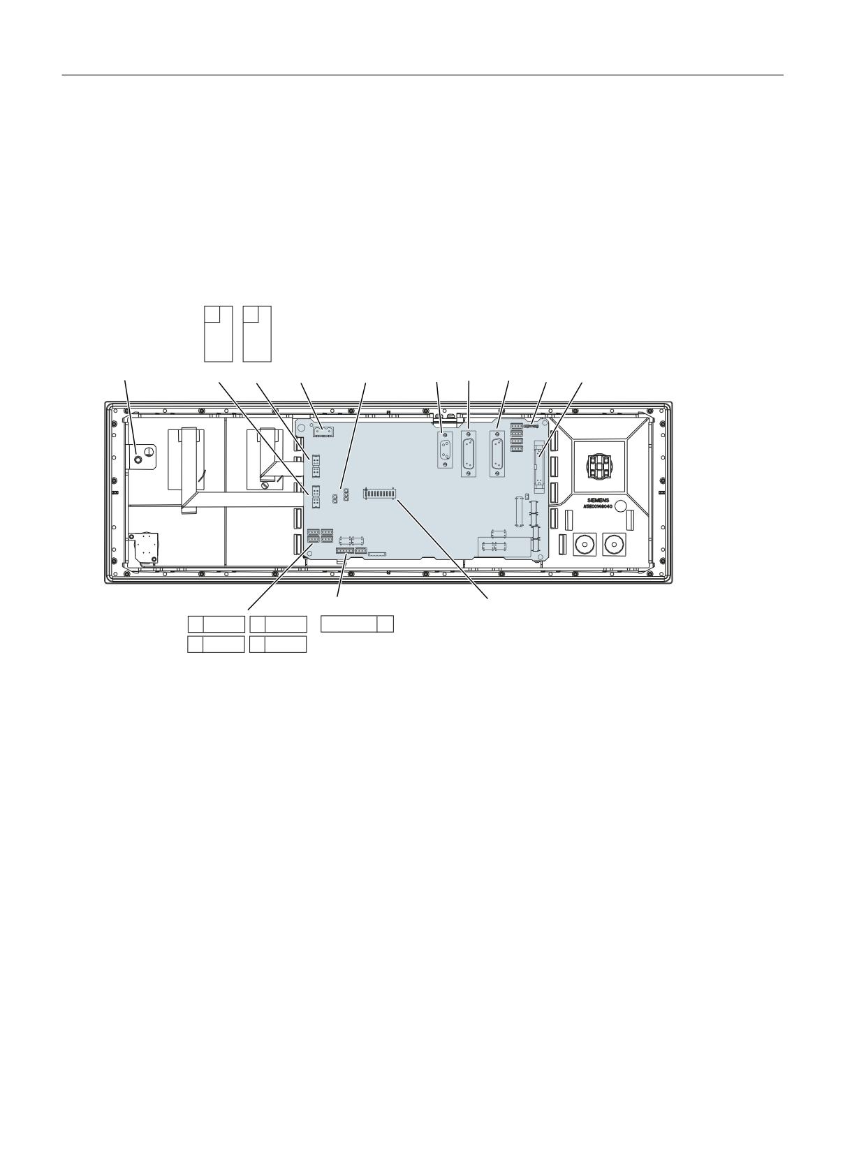
COM board
The control and display elements on the rear of the MCP 483 are located on the COM board
(shown with a gray backg6round in the illustration):
The detailed cutout under or above the interface name shows the position of pin 1 on the
connectors.
(TXLSRWHQWLDO ERQGLQJ
;
;
;
+
+
;
;
;
6
;
&20 %RDUG
;
;
;
6
;
;
Image 6-3
Rear of the MCP 483 showing the control and display elements and the interfaces
Jumper S1
Setting the handwheel signal type
- S1 open: TTL
- S1 closed: Differential interface
S3 DIP switch
Sets e.g. baud rate, addresses and protocol, see chapter Settings via DIP switch S3
(Page 123).
Diagnostic LEDs H1 ... H5
Please refer to Chapter LED displays (Page 136) for the various operating states that are
signaled using the LEDs.
Machine control panels
122
Manual, 03/2016, 6FC5397-1AP40-5BA3
Machine control panel: MCP 483
6.3 Interfaces
6.3
Interfaces
6.3.1
Overview
MCP 483 communication is handled by the COM board where the interfaces are located (see
Section: "Control and display elements" --> "Rear side").
Overview
● X10: Power supply interface
3-pin Phoenix terminal block
● X20: Operator panel interface (PROFIBUS DP)
9-pin Sub-D socket connector
● X30: Interface for connecting rotary feed override switch (23 graduations)
2 x 5-pin plug connector with lock
● X31: Interface for connecting rotary spindle override switch (16 graduations)
2 x 5-pin plug connector with lock
● X50: Interface to 4-way key-operated switch
1 x 6-pin plug connector
● X51-X54: Optional interfaces for customer-specific input/outputs (pushbuttons, incl. 24 V
lamps) each 1 x 4-pin plug connector
● X60/X61: Connection for two handwheels (TTL/DTTL)
15-pin sub-D socket each
● X70: Connection of direct control keys (16 digital inputs; opto-decoupled))
2 x 10-pin plug connector
● Equipotential bonding
The equipotential bonding conductor is attached by means of an M5 screw.
Pin assignment
For more detailed information, see "General information and networking", Chapter:
"Connecting".
6.3.2
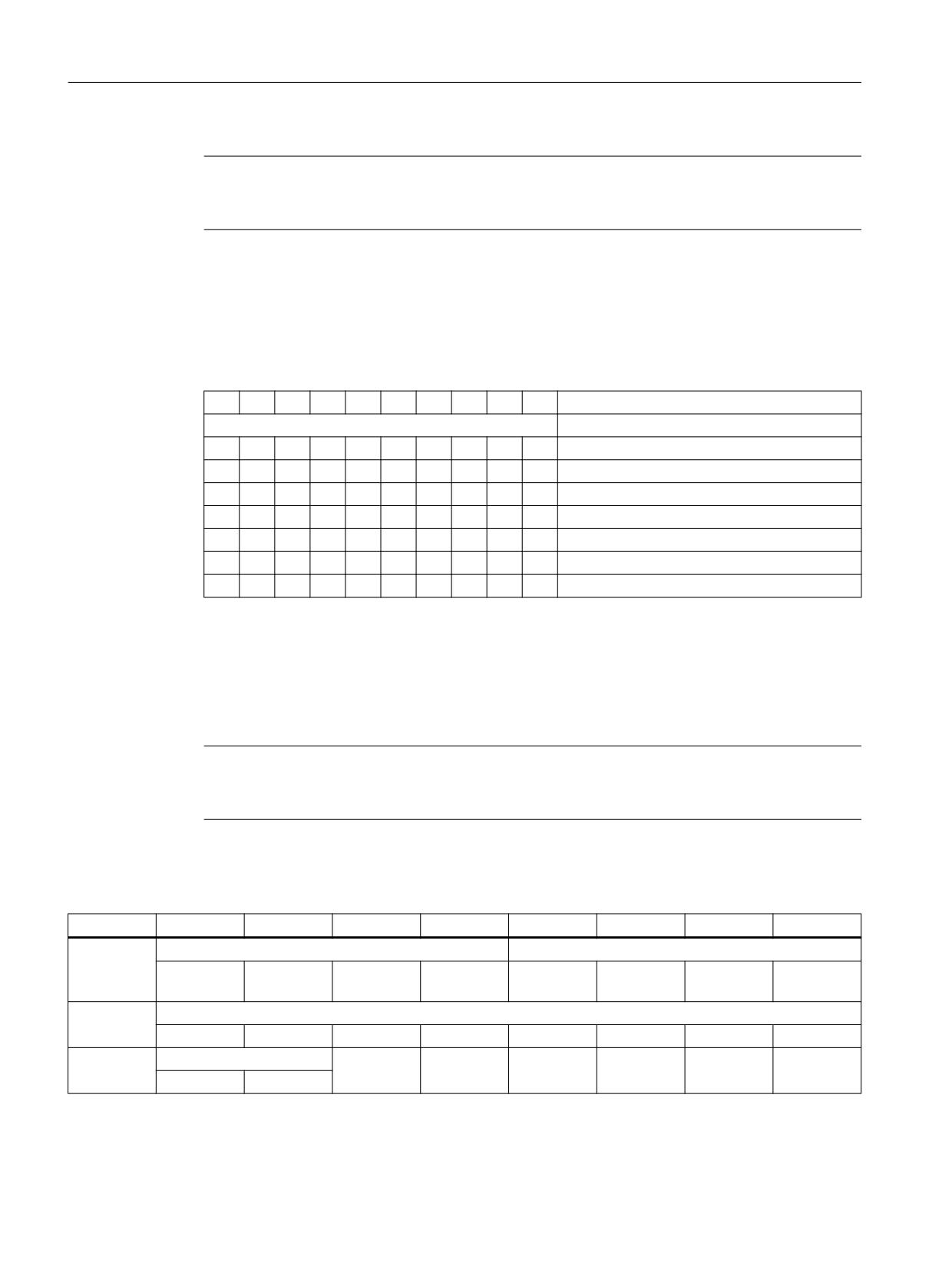
Settings via DIP switch S3
Delivery condition
Table 6-1
Delivery condition setting
1
2
3
4
5
6
7
8
9
10
Meaning/value
on
off
on
off
on
on
off
off
off
off
Series
Machine control panels
Manual, 03/2016, 6FC5397-1AP40-5BA3
123
Machine control panel: MCP 483
6.3 Interfaces
Note
The delivery condition setting MUST be changed in accordance with the "Assignment of the
DIP switch S3" table (below).
Connection type: PROFIBUS DP
For PROFIBUS DP, the PROFIBUS address is set using switches 1 to 10:
Table 6-2
Assignment of DIP switch S3
1
2
3
4
5
6
7
8
9
10
Meaning/value
PROFIBUS
off
off
off
off
off
off
off
-
on
on
0
on
off
off
off
off
off
off
-
on
on
1
off
on
off
off
off
off
off
-
on
on
2
on
on
off
off
off
off
off
-
on
on
3
:
:
:
:
:
:
:
-
-
-
: (etc.)
on
off
on
on
on
on
on
-
on
on
125
off
on
on
on
on
on
on
-
on
on
126
6.3.3
Input / output images
The specifications for assigning input and output bytes listed in the tables can be changed in
the PLC via parameter assignment.
Note
The following applies in respect of the process input and output images in the tables: n is
defined by means of FB1 parameters in OB100 of the PLC.
Table 6-3
Input image MCP 483 - standard
Byte
Bit7
Bit6
Bit5
Bit4
Bit3
Bit2
Bit1
Bit0
n + 0
Spindle override
Mode
OV_SP8
OV_SP4
OV_SP2
OV_SP1
JOG
TEACH IN
MDA
AUTO
X31.7
X31.8
X31.9
X31.10
n + 1
Machine function
REPOS
REF.
INC [VAR]
INC 10000
INC 1000
INC 100
INC 10
INC 1
n + 2
Key-operated switch
SPINDLE
* SPINDLE
FEED
* FEED
CYCLE
*CYCLE
START
STOP
START
STOP
START
STOP
Position 0
Position 2
Machine control panels
124
Manual, 03/2016, 6FC5397-1AP40-5BA3
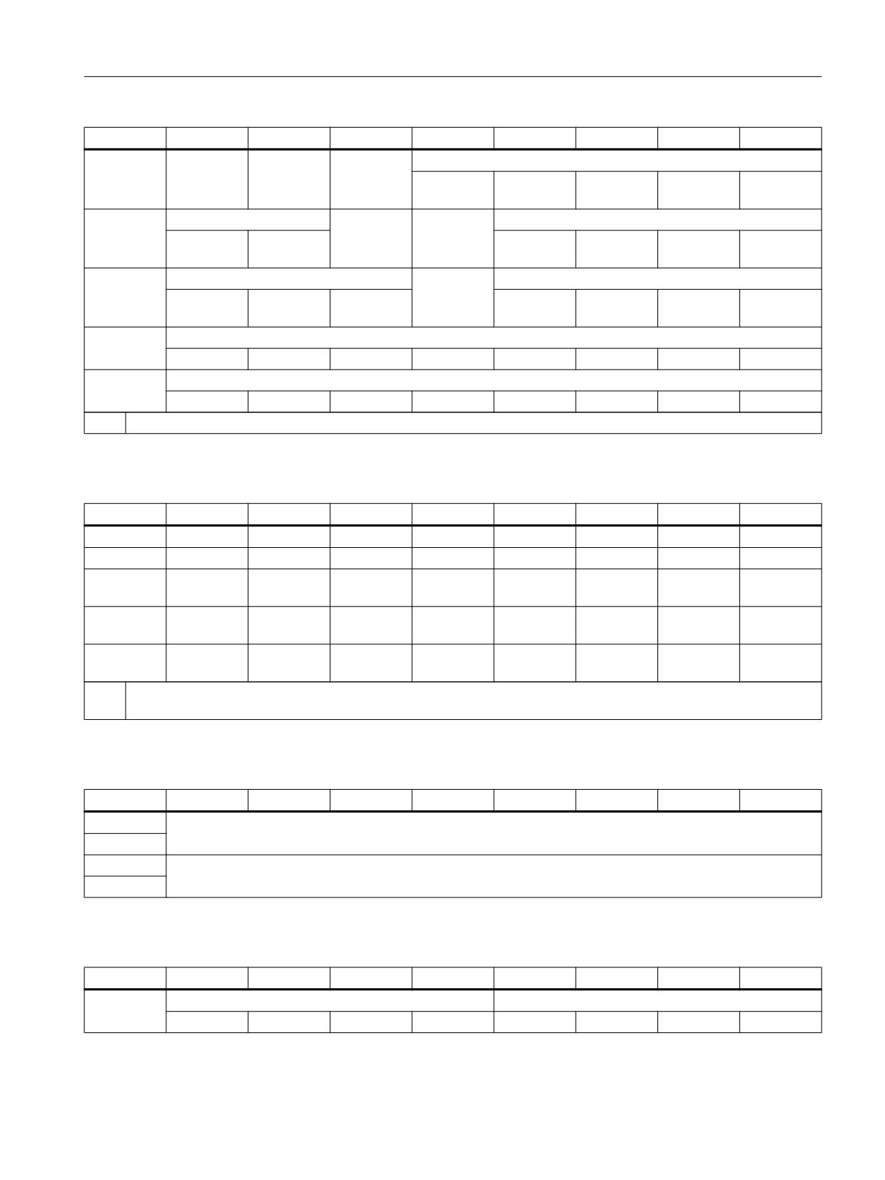
Machine control panel: MCP 483
6.3 Interfaces
Byte
Bit7
Bit6
Bit5
Bit4
Bit3
Bit2
Bit1
Bit0
n + 3
RESET
Keyswitch
SINGLE
Feedrate override
BLOCK
OV_VS16
OV_VS8
OV_VS4
OV_VS2
OV_VS1
position 1
X30.6
X30.7
X30.8
X30.9
X30.10
n + 4
Traversing direction
RAPID
Keyswitch
Axis selection
(R14)
+
-
X
4
7
position 3
(R15)
(R13)
(R1)
(R4)
(R7)
(R10)
n + 5
Axis selection
WCS MCS
Axis selection
Y
Z
5
9
8
6
(R2)
(R3)
(R5)
(R11)
(R9)
(R8)
(R6)
n + 6
Freely assignable customer keys
T9
T10
T11
T12
T13
T14
T15
-
n + 7
Freely assignable customer keys
T1
T2
T3
T4
T5
T6
T7
T8
*
Inverse signals
Table 6-4
Input image MCP 483 - supplementary I/O
Byte
Bit7
Bit6
Bit5
Bit4
Bit3
Bit2
Bit1
Bit0
m + 0
DT8
DT7
DT6
DT5
DT4
DT3
DT2
DT1
m + 1
DT16
DT15
DT14
DT13
DT12
DT11
DT10
DT9
m + 2
-
-
KT-IN6
KT-IN5
KT-IN4
KT-IN3
KT-IN2
KT-IN1
X52.3
X52.2
X52.1
X51.3
X51.2
X51.1
m + 3
-
-
-
OV_VS16
OV_VS8
OV_VS4
OV_VS2
OV_VS1
X30.6
X30.7
X30.8
X30.9
X30.10
m + 4
-
-
-
OV_SP16
OV_SP8
OV_SP4
OV_SP2
OV_SP1
X31.6 1)
X31.7 1)
X31.8 1)
X31.9 1)
X31.10 1)
1)
If the 4-stage rotary spindle override switch on X31 is replaced by a 5-stage rotary switch, the input information here
can be measured in 5 stages.
Table 6-5
Input image MCP 483 - handwheel
Byte
Bit7
Bit6
Bit5
Bit4
Bit3
Bit2
Bit1
Bit0
p + 0
Counter status, handwheel 1 at X60
(16 bits signed, in the big endian format)
p + 1
p + 2
Counter status, handwheel 2 at X61
(16 bits signed, in the big endian format)
p + 3
Table 6-6
Output image for MCP 483 - standard
Byte
Bit7
Bit6
Bit5
Bit4
Bit3
Bit2
Bit1
Bit0
n + 0
Machine function
Mode
1000 INC
100 INC
10 INC
1 INC
JOG
TEACH IN
MDA
AUTO
Machine control panels
Manual, 03/2016, 6FC5397-1AP40-5BA3
125
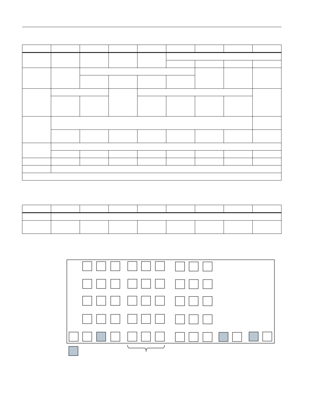
Machine control panel: MCP 483
6.3 Interfaces
Byte
Bit7
Bit6
Bit5
Bit4
Bit3
Bit2
Bit1
Bit0
n + 1
FEED
FEED
CYCLE
CYCLE
Machine function
START
STOP
START
STOP
REPOS
REF.
INC [VAR]
INC 10000
n + 2
Traversing
Axis selection
SINGLE
SPINDLE
SPINDLE
direction -
BLOCK
START
STOP
X
4
7
(R13)
(R1)
(R4)
(R7)
(R10)
n + 3
Axis selection
WCS MCS
Axis selection
Traversing
direction
Z
5
9
8
6
(R3)
(R5)
(R11)
(R9)
(R8)
(R6)
+
(R15)
n + 4
Freely assignable customer keys
Axis selec-
tion
T9
T10
T11
T12
T13
T14
T15
Y
(R2)
n + 5
Freely assignable customer keys
T1
T2
T3
T4
T5
T6
T7
T8
n + 6
-
-
-
-
-
-
RESET
(R14)
n + 7
Reserved
Signals marked with * are inverse signals.
Table 6-7
Output image MCP 483 - supplementary I/O
Byte
Bit7
Bit6
Bit5
Bit4
Bit3
Bit2
Bit1
Bit0
m + 0
Reserved
m + 1
-
-
KT-OUT6
KT-OUT5
KT-OUT4
KT-OUT3
KT-OUT2
KT-OUT1
X54.3
X54.2
X54.1
X53.3
X53.2
X53.1
Default key assignment
-2*
REP
REF
(T1)
(T2)
(T3)
X
Y
Z
(R1)
(R2)
(R3)
TCH
INC
INC
(T4)
(T5)
(T6)
4
5
6
VAR
1
(R4)
(R5)
(R6)
MDA
INC
INC
(T7)
(T8)
(T9)
7
8
9
10
100
(R7)
(R8)
(R9)
AUT
INC
INC
(T10)
(T11)
(T12)
WKS
1000
10000
(R10)
(R11)
(R12)
RESET
Einzel-
NC-
NC-
(T13)
(T14)
(T15)
-
Eilg.
+
Sp.-
Sp.-
VS-
VS-
satz
STOP
START
(R13)
(R14)
(R15)
STOP
START
STOP
START
,QSXWV LQYHUWHG
7
7
XQODEHOHG NH\V
Image 6-4
MCP 483 default key assignment
Machine control panels
126
Manual, 03/2016, 6FC5397-1AP40-5BA3
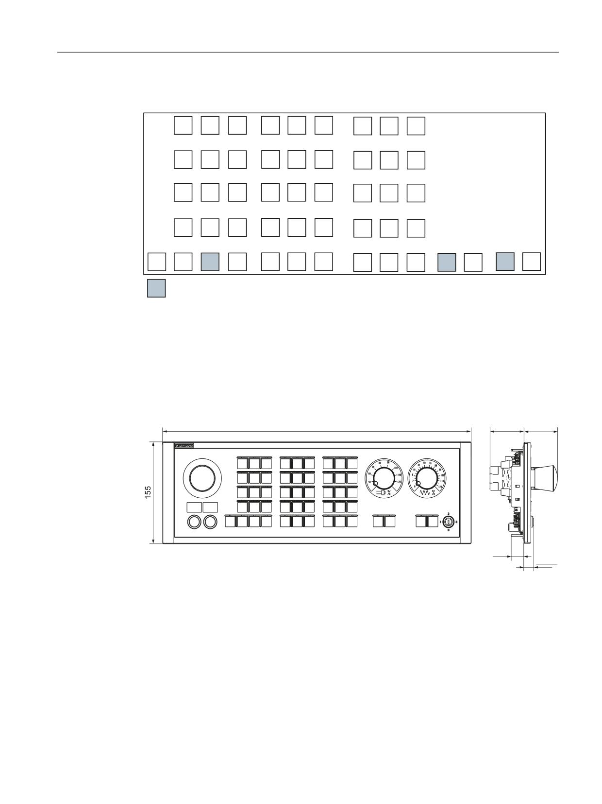
Machine control panel: MCP 483
6.4 Mounting
Assignment of the inputs (I) and outputs (O) to the keys and LEDs
(
(
(
(
(
(
(
(
(
$
$
$
$
$
$
$
$
$
(
(
(
(
(
(
(
(
(
$
$
$
$
$
$
$
$
$
(
(
(
(
(
(
(
(
(
$
$
$
$
$
$
$
$
$
(
(
(
(
(
(
(
(
(
$
$
$
$
$
$
$
$
$
(
(
(
(
(
(
(
(
(
(
(
(
(
(
$
$
$
$
$
$
$
$
$
$
$
$
$
$
,QSXWV LQYHUWHG
Image 6-5
Inputs and outputs of the MCP 483 keyboard
6.4
Mounting
Dimension drawing
Image 6-6
Dimension drawing for machine control panel MCP 483
Machine control panels
Manual, 03/2016, 6FC5397-1AP40-5BA3
127
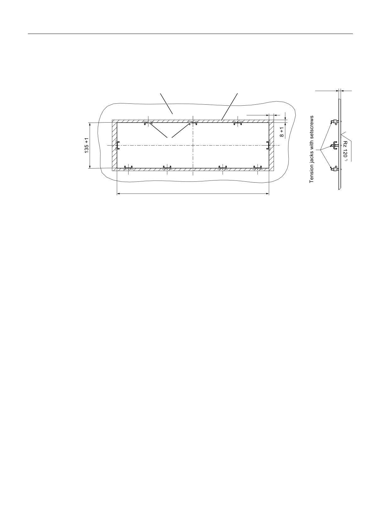
Machine control panel: MCP 483
6.4 Mounting
Tension jacks
The machine control panel is attached using 9 tension jacks (tightening torque, 0.8 Nm).
0RXQWLQJ SDQHO
6HDOLQJ DUHD
3UHVVXUH SRLQWV
IRU WHQVLRQ MDFNV
,Q WKH VHDOLQJ DUHD
Image 6-7
MCP483_mounting
Mounting position
Max. 60° to the vertical. For mounting positions greater than 60°, a fan must also be installed
to keep the ambient temperature of the machine control panel constantly below 55° C.
Machine control panels
128
Manual, 03/2016, 6FC5397-1AP40-5BA3
Machine control panel: MCP 483
6.5 PROFIBUS communication
6.5
PROFIBUS communication
6.5.1
Overview
This section describes:
● Requirements for adding a DP slave MCP to the hardware configuration for a SIMATIC S7
project.
● Configuring a DP slave MCP with STEP7 "HW config."
● Details of how to link the DP slave MCP to the basic PLC program and user program
(optional).
Note
The instructions given in this chapter are essentially limited to the special requirements for
configuring the DP slave MCP. For more details about working with SIMATIC STEP 7
please refer to the relevant SIMATIC documentation or online help.
Note
Both units can be linked up using the supplied 20-pin ribbon cable in order to transfer the
direct key signals of the operator panel front to the COM board of the machine control panel.
The direct key module therefore no longer needs to be connected.
6.5.2
Prerequisites
The following components are needed as prerequisites for adding a DP slave MCP to the
hardware configuration:
● SIMATIC STEP 7 as of Version 5.4, Service Pack 4
● Toolbox 840D sl as of Version 2.6
Hardware configuration
The DP slave MCP is shown in SIMATIC STEP 7 in the hardware catalog of “HW Config” under
the following path:
Profile: Standard
PROFIBUS DP > Other field devices > NC/RC > Motion Control > SINUMERIK MCP
If the module is not displayed, the GSD file must be installed. To do this, in "HW config" use
menu command Tools > Install new GSD file.
Note
The GSD file of the DP slave MCP is located on the Toolbox CD in the directory:
...\8x0d\GSD\MCP_310_483
Machine control panels
Manual, 03/2016, 6FC5397-1AP40-5BA3
129
Machine control panel: MCP 483
6.5 PROFIBUS communication
6.5.3
Functions of the machine control panel
The machine control panel offers the following functions:
● Standard
The input/output data of the function keys and user-specific keys and outputs are
transferred:
- Input data: 8 bytes
- Output data: 8 bytes
● Handwheel
The absolute values of the two handwheels that can be connected to the machine control
panel are transferred.
● Additional I/Os
The data of the following non-default inputs/outputs is transferred:
- Direct keys
- Customer keys
- Rotary switch
6.5.4
Configuring the DP slave MCP
This section describes how to configure a DP slave MCP with reference to the hardware
configuration for a SIMATIC S7 project shown in the figure by way of example.
The hardware configuration has the following modules:
● SIMATIC Station 300 with SINUMERIK 840D sl
● SINUMERIK MCP with module: Standard + handwheel + additional I/O
Procedure
Configuring the DP slave MCP as an S7 project involves the following steps:
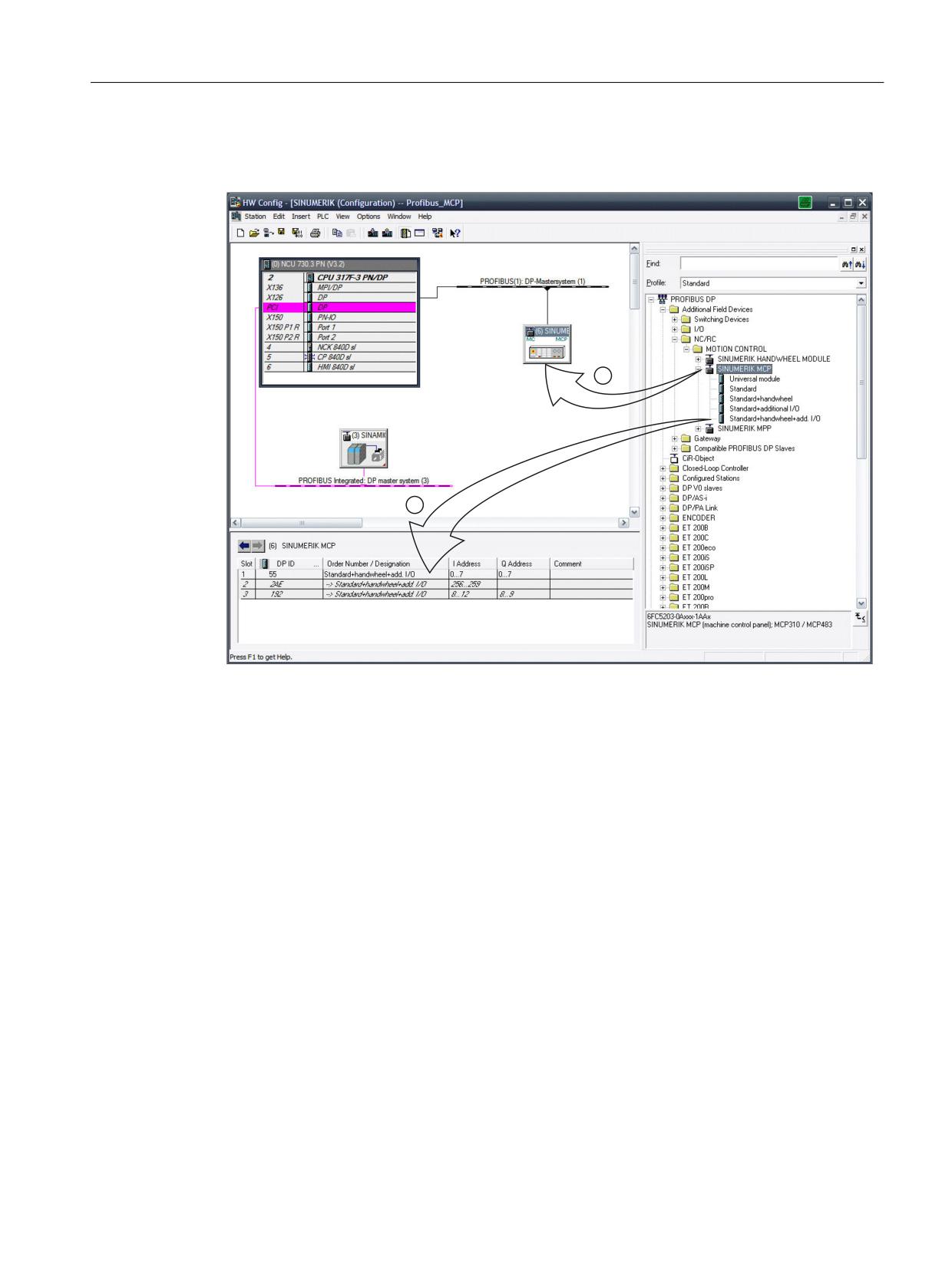
1. Add the DP slave MCP to the configuration ①.
2. Set the PROFIBUS address.
Machine control panels
130
Manual, 03/2016, 6FC5397-1AP40-5BA3
Machine control panel: MCP 483
6.5 PROFIBUS communication
3. Add the appropriate module to the DP slave MCP depending on the required functions
②.
4. Set the I/O addresses of the individual slots.
Image 6-8
Configuration with DP slave MCP
Requirements: S7 project
The following status is required for the S7 project to which the DP slave MCP is to be added:
● The S7 project has been created.
● A SIMATIC 300 station with SINUMERIK controller has been defined.
Adding a DP slave MCP
To add a DP slave MCP to the configuration, open the hardware catalog using the menu
command View > Catalog.
The DP slave MCP can be found at profile: Standard
PROFIBUS DP > Other field devices > NC/RC > Motion Control > SINUMERIK MCP
Click with the left mouse button on the DP slave MCP (SINUMERIK MCP) in the hardware
catalog and drag it onto the DP master system in the station window by holding down the left
mouse button.
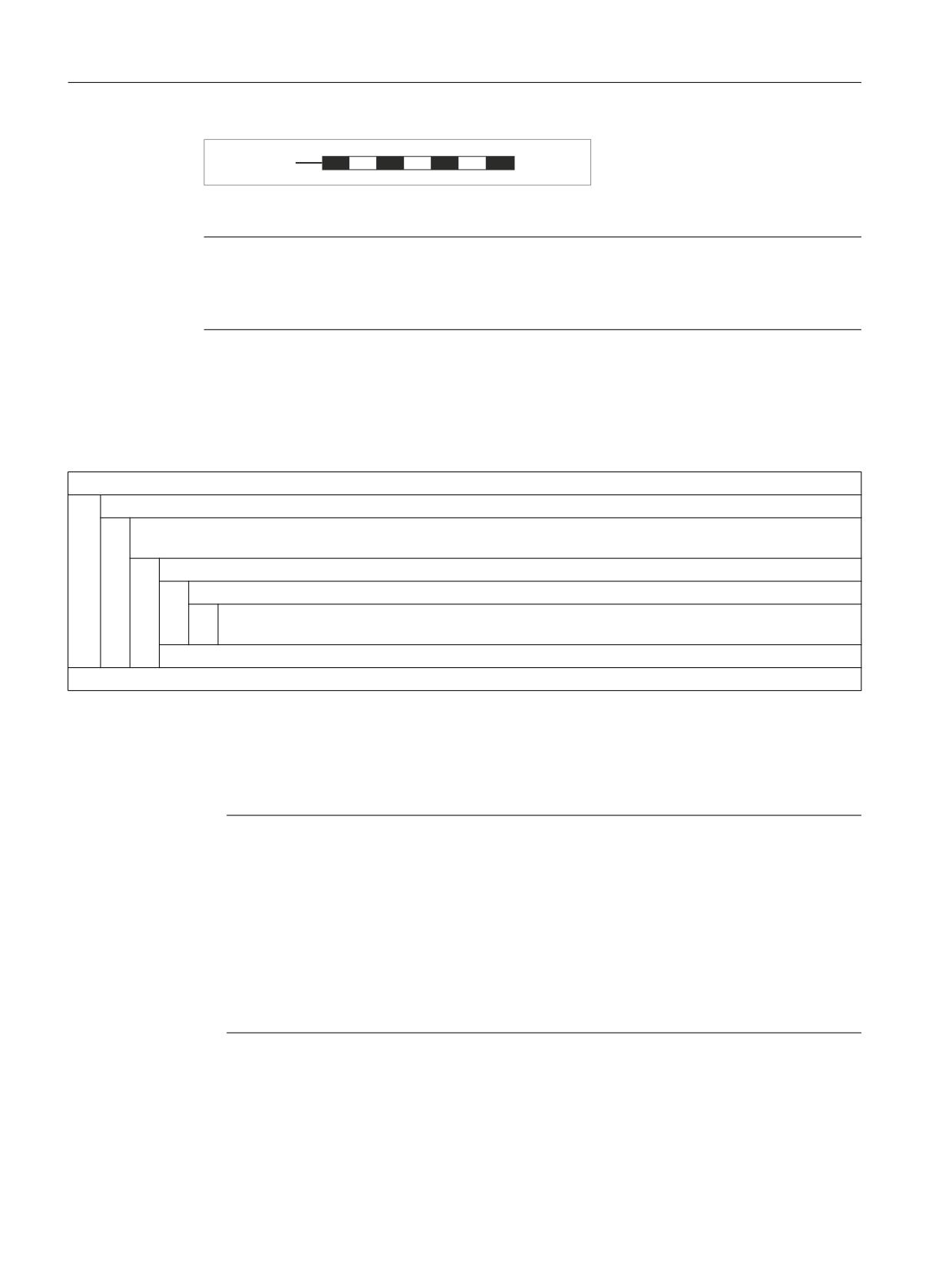
The DP master system is displayed in the station window with the following symbol:
Machine control panels
Manual, 03/2016, 6FC5397-1AP40-5BA3
131
Machine control panel: MCP 483
6.5 PROFIBUS communication
When you release the left mouse button, the DP slave MCP is added to the configuration.
Note
As you drag the DP slave the cursor appears as a circle with a slash through it. When the
cursor is positioned exactly over the DP master system, it changes to a plus sign, and the DP
slave can be added to the configuration.
PROFIBUS parameters
As soon as you have inserted the MCP DP slave into the configuration, the "Properties -
PROFIBUS interface SINUMERIK MCP" dialog box is displayed:
Dialog: Properties - PROFIBUS interface SINUMERIK MCP
Tab card: Parameters
Address: <PROFIBUS address>
Button: "Properties..."
Dialog: PROFIBUS properties
Tab card: Network settings
Data transfer rate: 12 Mbaud
Profile: DP
OK
OK
The following PROFIBUS parameters must either be set or verified:
● PROFIBUS address
● Data transfer rate
● Profile
Note
No automatic comparison of the PROFIBUS address!
The PROFIBUS address of the DP slave MCP set in the S7 project must match the
PROFIBUS address set on the module (DIP switch S3) (see Section: "Settings via DIP
switch S3")
The following data must agree:
1. SIMATIC S7 configuration DP slave MCP: PROFIBUS address
2. Machine control panel DIP switch S3: PROFIBUS address
3. FB1 call in OB100: "MCP1BusAdr := "
Machine control panels
132
Manual, 03/2016, 6FC5397-1AP40-5BA3
Machine control panel: MCP 483
6.5 PROFIBUS communication
Adding a module
The active functions and hence the number of user data elements to be transferred are chosen
by selecting the appropriate pre-configured module. The following modules are available in
HW Config under "SINUMERIK MCP":
● Universal module (not applicable)
● Standard
● Standard + handwheel
● Standard + additional I/O
● Standard + handwheel + additional I/O
I/O addresses
If you add a module to slot 1 of the DP slave MCP, the I/O addresses are automatically assigned
by STEP 7.
Double clicking with the left mouse button on a slot opens the "Properties - DP Slave" dialog
box. This dialog box can be used to set the start addresses of the I/O data of the slot.
6.5.5
Linking the DP slave MCP
This chapter describes how to link the DP slave MCP
● In the basic PLC program for transferring the standard input/output data in the VDI interface
● To the PLC user program (optional) to implement a user-specific response to a module
failure
Note
Processing of additional I/O data is the sole responsibility of the user (machine
manufacturer) and is not supported by the PLC basic program.
PLC basic program
To transfer the standard I/O data of the MCP DP slave via the PLC basic program, the
corresponding I/O range must be entered in the communication parameters of the FB1 function
block.
Function block FB1
The communications parameters of the MCP are called MCPx... (x = 1 or 2) in function block
FB1. A maximum of 2 machine control panels are supported by the basic PLC program.
To synchronize several MCPs, the PLC program must be adapted accordingly. This is the
user's (machine manufacturer's) responsibility.
Machine control panels
Manual, 03/2016, 6FC5397-1AP40-5BA3
133

Machine control panel: MCP 483
6.5 PROFIBUS communication
To operate an MCP 483 machine control panel as DP slave, only the parameters listed in the
following table are relevant for the FB1 call in the OB100:
parameters
Type
Description
Value
MCPNum:
INT
Number of active MCPs
:=1
MCP1In:
POINTER
Start address of the input signals
:= P#E 0.0
MCP1Out:
POINTER
Start address of the output signals
:= P#A 0.0
MCP1StatSend
POINTER
Status data word for sending
:= P#A 8.0
MCP1StatRec
POINTER
Status data word for receiving
:= P#A 12.0
MCP1BusAdr
INT
≙ S3 switch position on the MCP
:=6
MCP1Timeout
S5time
Cyclic sign-of-life monitoring of the MCP
:= S5T#700MS
MCP1Cycl
S5time
Time reference for the cyclic updating of the signals to the MCP
:= S5T#200MS
MCPBusType
BYTE
33 ≙ PROFIBUS (55 ≙ Ethernet)
:= B#16#33
VDI interface parameter assignment
The following function modules are available for assigning the VDI interface parameters:
● FC 19: Transfer the signals for wide MCP, M (milling) version
● FC 25: Transfer the MCP signals, T (turning) version
Note
The FC 19, FC 19 and FC 25 function blocks are part of the basic PLC program. It is the
user's (machine manufacturer's) responsibility to call the block correctly and/or assign the
interface the appropriate parameters.
References
A detailed description of the function blocks for transferring the machine control panel signals
is available in:
Function Manual, Basic Functions: P3, Basic PLC Program
PLC user program
If an MCP is connected via PROFIBUS DP, the basic PLC program does not check for module
failure.
In this case the MCP is monitored by a standard mechanism to monitor the active DP slave:
● PLC operating system
● PROFIBUS controller
If a failure of a DP slave MCP is detected, the PLC defaults to STOP.
Customized response
The following organization blocks can be added to the PLC user program to customize the
response to a DP slave MCP failure:
● OB 82: Diagnostics interrupt
● OB 86: Rack failure
Machine control panels
134
Manual, 03/2016, 6FC5397-1AP40-5BA3
Machine control panel: MCP 483
6.6 Maintenance and Service
Please refer to the corresponding SIMATIC literature for details of linking organization blocks
and evaluating diagnostic data.
Note
In the event of the failure of a connected machine control panel, the PLC basic program
performs the following:
● Alarm "40026x machine control panel (x+1) failure"; with x = 0, 1 is initiated.
● The corresponding interface signal "MCP 1/2 ready" in the DB10.DBB104 is reset.
6.6
Maintenance and Service
Cleaning the device
Use a soft cloth moistened either with water or a mild cleaning agent to clean the housing and
operator control elements of the machine control panel.
Checking the device
In order to prevent foreign bodies or liquids entering the machine control panel, regularly check
the device
● that all the housing screws are in place and tight
● for damage to the housing
● for damage to the cable cover or cable entry
Protect the device from environmental effects
Protect the machine control panel against
● direct solar radiation and heat sources
● mechanical vibration and shock
● dust
● moisture, and
● strong magnetic fields
Checking the emergency stop button
Check the emergency stop button regularly to ensure that it functions correctly.
Machine control panels
Manual, 03/2016, 6FC5397-1AP40-5BA3
135
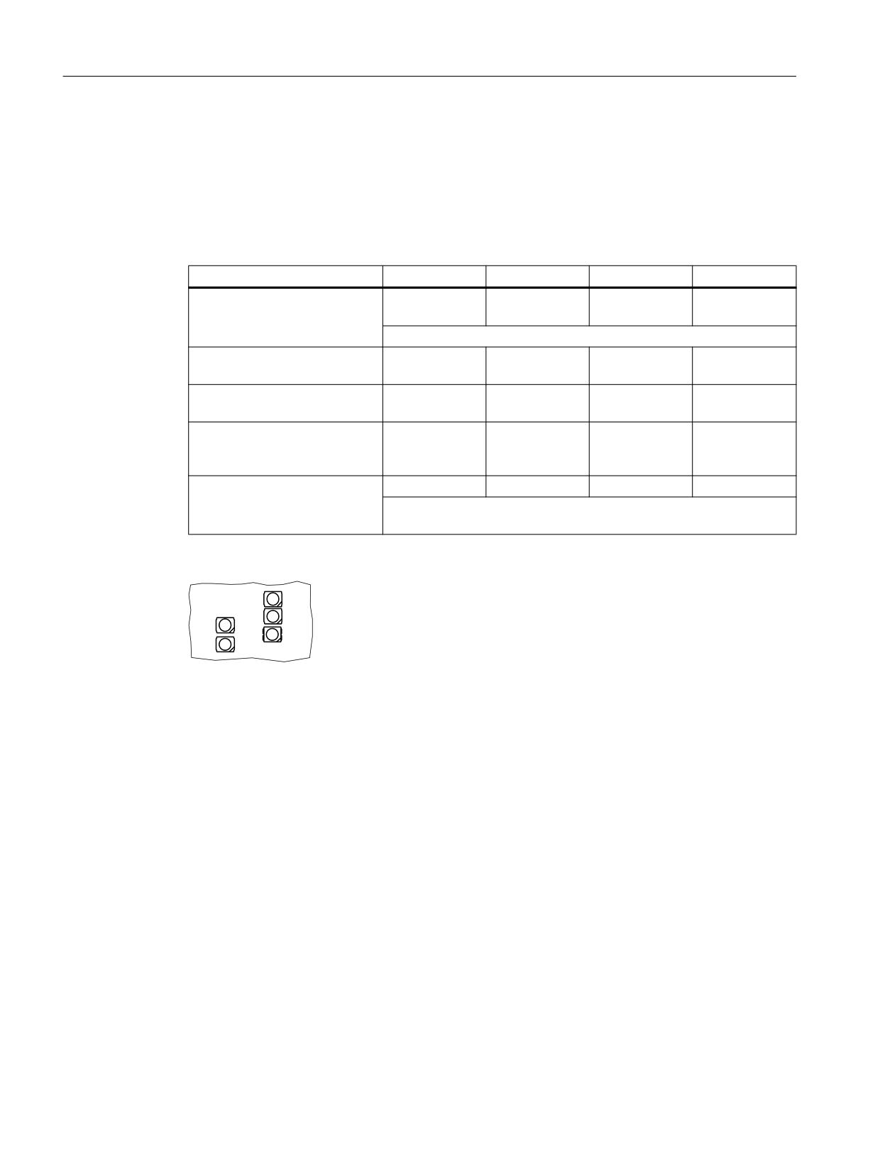
Machine control panel: MCP 483
6.7 Diagnostics
6.7
Diagnostics
6.7.1
LED displays
LEDs H1 to H5 on the COM board provide information about the following states:
Diagnostics
H1
H3
H4
H5
Power On
Lights up red
Lights up green
Lights up or-
Lights up red/off
ange
The LEDs light up for approx. 4 s.
GD communication
Off
Lights up green
Flashes orange
Lights up red
(80 Hz)
There is no PROFIBUS com-
Lights up red
Lights up green
Off
Flashes green
munication.
(bus error)
(approx. 25 Hz)
MCP is configured as PROFI-
Off
Lights up green
Off/orange
Lights up green
BUS slave and with cyclic data
exchange.
Fatal error LED display
flashes red
flashes green
flashes orange
flashes green
For fatal software errors and incorrect DIP switch settings, the LEDs
flash very quickly.
LED H2 is reserved for service and is always off.
+
+
+
+
+
Image 6-9
Arrangement of the LEDs on the COM board
6.7.2
Output functions
Preconditions
● The MCP is booting.
● The MCP is not communicating with the control system/ PROFIBUS master, i.e. all of the
LEDs in the keys are flashing.
In this state, the output functions described in the following can be sequentially called.
1. Software version
Simultaneously press the "FEED START" and "FEED STOP" keys.
The software version is output using three digits. The individual digits are expressed by the
number of LEDs in the keys that are switched on.
Machine control panels
136
Manual, 03/2016, 6FC5397-1AP40-5BA3
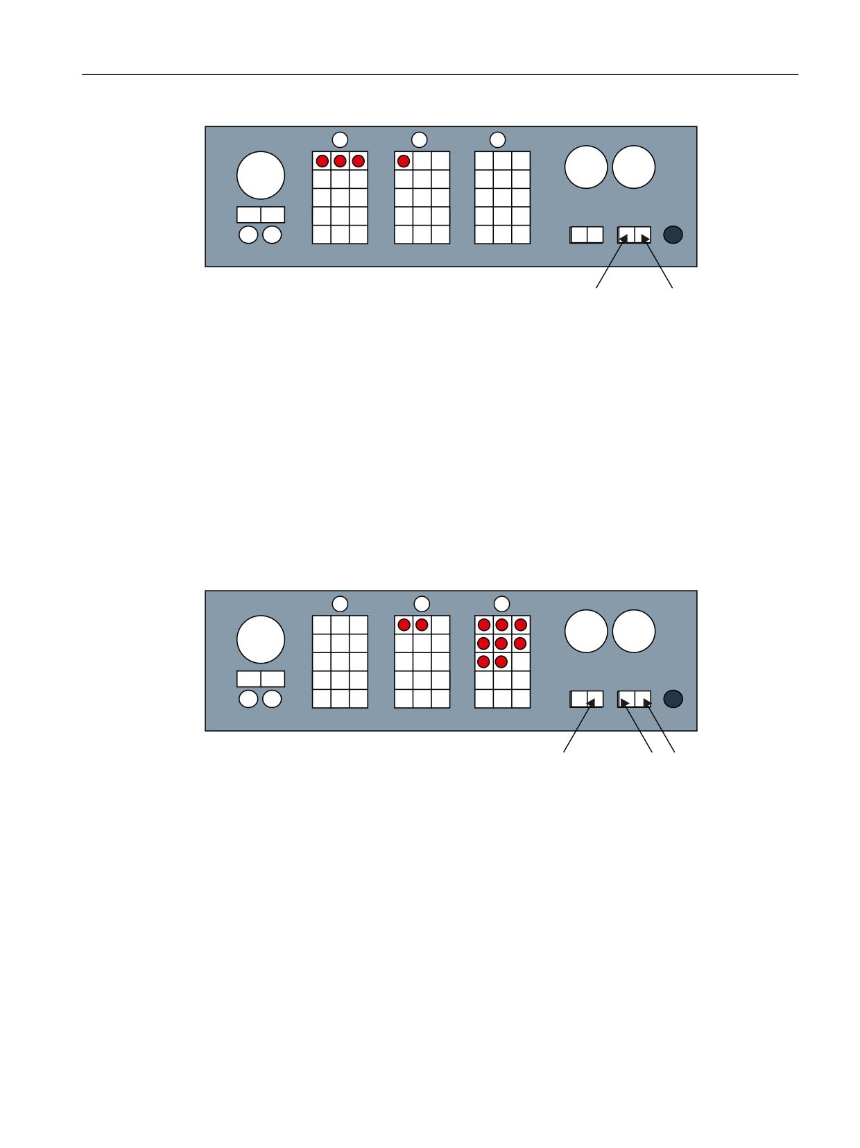
Machine control panel: MCP 483
6.7 Diagnostics
)(('
)(('
6723
67$57
①
1. Digit of the software version
②
2. Digit of the software version
③
3. Digit of the software version
Image 6-10 Example: Output of the actual software version "03.01.00.00"
2. Output of the bus address
Keep the FEED keys pressed, and in addition press the SPINDLE START" key.
The actual bus address of the MCP is output by the number of LEDs in the keys that are
switched on:
PROFIBUS: Value range 0 … 126
MPI: Value range 0 … 15
63,1'/(
)(('
)(('
67$57
6723
67$57
① Hundreds position of the bus address
② Tens position of the bus address
③ Ones position of the bus address
Image 6-11 Example: Output of PROFIBUS address "28"
3. Output of the bus system
Keep the FEED keys pressed, and press the SPINDLE START" key again.
The LEDs in the keys indicate the bus system in which the MCP is integrated: MPI or
PROFIBUS (PB).
Machine control panels
Manual, 03/2016, 6FC5397-1AP40-5BA3
137

Machine control panel: MCP 483
6.7 Diagnostics
63,1'/(
)(('
)(('
67$57
6723
67$57
Image 6-12 Example: Output of the bus system "PB" (PROFIBUS)
6.7.3
Key test
Preconditions
● The MCP is booting.
● The MCP is not communicating with the control system/ PROFIBUS master, i.e. all of the
LEDs in the keys are flashing.
In this state, the operating functions described in the following can be executed in the test
mode.
Test mode
● Activation: Press the "RESET" key.
● Automatic deactivation: No operator control was pressed in the last 3 seconds.
● Manual deactivation: Simultaneously press the "CYCLE STOP" and "CYCLE START" keys.
Operating functions
● Function of the keys and their associated LEDs:
When pressing a key, the associated LED is switched on.
● Function of the rotary switch
Each time the rotary switch is turned, an LED is switched on in sequence in the form of a
running light.
● Function of the key-operated switch:
When the key-operated switch is turned, positions 0 - 3 are displayed by 0 up to three LEDs.
Machine control panels
138
Manual, 03/2016, 6FC5397-1AP40-5BA3
Machine control panel: MCP 483
6.8 Technical data
6.8
Technical data
Machine control panel MCP 483
Safety
Safety class
III; PELV according to EN 50178
Degree of protection accord-
Front side:
Key-operated switch:
Rear side:
ing to EN 60529
IP65
IP54
IP00
Approvals
CE
Electrical data
Input voltage
24 VDC
Power consumption, max.
Board:
Lamps:
Handwheels:
Total:
7 W
14.4 W (6 x 2.4 W) *)
2 x 0.9 W
23.2 W
Mechanical data
Dimensions
Width: 483 mm
Depth: 70 mm
Height: 155 mm
Mounting depth: 38 mm
Distance from NCU/PCU
PROFIBUS DP: 100 m
Weight:
Approx. 1.6 kg
*) The outputs for the illuminated pushbuttons (X53/X54) can have a max. permissible current of 0.3 A.
However, the total current consumption of the components must not exceed 1.0 A (24 W).
Note
Information about the climatic and mechanical environmental conditions is contained in the
associated section under:
"General notes and interconnection" → "Operational planning".
Emergency Stop button
Rated voltage
24 VDC
Current magnitude, max.
3 A
Current magnitude, min.
1 mA
Switching capacity
DC 13 according to EN 60947-5-1
Conditional rated short-circuit current
10 A gL/gG according to EN 60947-5-1
B10d
500 000
Note
The quantitative assessment of the emergency stop safety function must be based on the
B10d values corresponding to the used standards (e.g. ISO 13849-1) under consideration of
the respective application (frequency of the actuation, service life, diagnostics by the evaluation
unit, etc.). The B10d values only apply when the technical properties of the emergency stop
button are taken into account.
Machine control panels
Manual, 03/2016, 6FC5397-1AP40-5BA3
139
Machine control panel: MCP 483
6.9 Accessories and spare parts
6.9
Accessories and spare parts
6.9.1
Overview
Table 6-8
Accessories and spare parts for machine control panel 483
Name
Description
Qua
Article number
ntity
22 mm actuating element, 40 mm mushroom
1
3SB3000-1HA20 *)
pushbutton, snap action with tamper protec-
Emergency stop
tion, latching, red, with holder, unlit
button
Contact block with 2 contacts, 1 NO + 1 NC,
1
3SB3400-0A *)
2-pole ,screw terminal
Keyswitch
Keyswitch with key
1
6FC5247-0AF02-0AA0
Key
Ten key sets, each with three keys for the
1
6FC5148-0AA03-0AA0
keyswitch settings 1, 2, 3
set
Tension jacks
Tension jack set (9 items) for supplementary
1
6FC5248-0AF14-0AA0
components with 2.5 mm profile, length: 20
set
mm
Override
Electronic rotary switch 1x16G, T=24, cap,
1
6FC5247-0AF12-1AA0
spindle / rapid tra-
button, pointer, spindle dials and rapid tra-
verse
verse
Override
Electronic rotary switch 1x23G, T=32, cap,
1
6FC5247-0AF13-1AA0
feed / rapid tra-
button, pointer, feed and rapid-traverse dials
verse
Slide-in
Can be written, (3 films, A4)
1 set
6FC5248-0AF22-1AA1
labels
Cables
Cable set (60 units) for additional control de-
1 set
6FC5247-0AA35-0AA0
vices for the machine control panels
Length: 500 mm
*) Safety-related
Machine control panels
140
Manual, 03/2016, 6FC5397-1AP40-5BA3
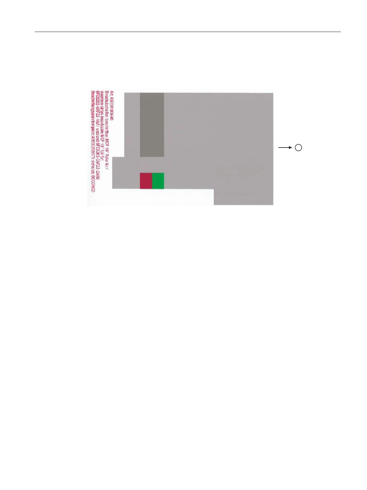
Machine control panel: MCP 483
6.9 Accessories and spare parts
6.9.2
Membrane keyboard: Labeling the slide-in labels
You can create your own slide-in labels to label the keys differently. Use the blank films that
can be printed for this purpose.
Image 6-13 Blank film for MCP 483
Preparing slide-in labels
Instructions are given below on how to print the required key symbols on the supplied film or
how to create your own individual film:
The DOConCD or CD included in Catalog NC 61/ NC 62 includes four files for printing the
blank films:
● Template_M_MCP483.doc [default assignment for milling - standard; (A)]
● Template_T_MCP483.doc [defaults for turning; (B)]
● Template_MCP483.doc [blank template for film: Item No. A5E00205579; (C)]
● Symbols.doc Key symbols as Word file, inscription on labels as jpg file (D)
Files Template_M_MCP483.doc, Template_T_MCP483.doc and Template_MCP483.doc
include a table function showing the corresponding keyboard positions.
An example of each of the MCP files (milling and turning) is given below:
Machine control panels
Manual, 03/2016, 6FC5397-1AP40-5BA3
141
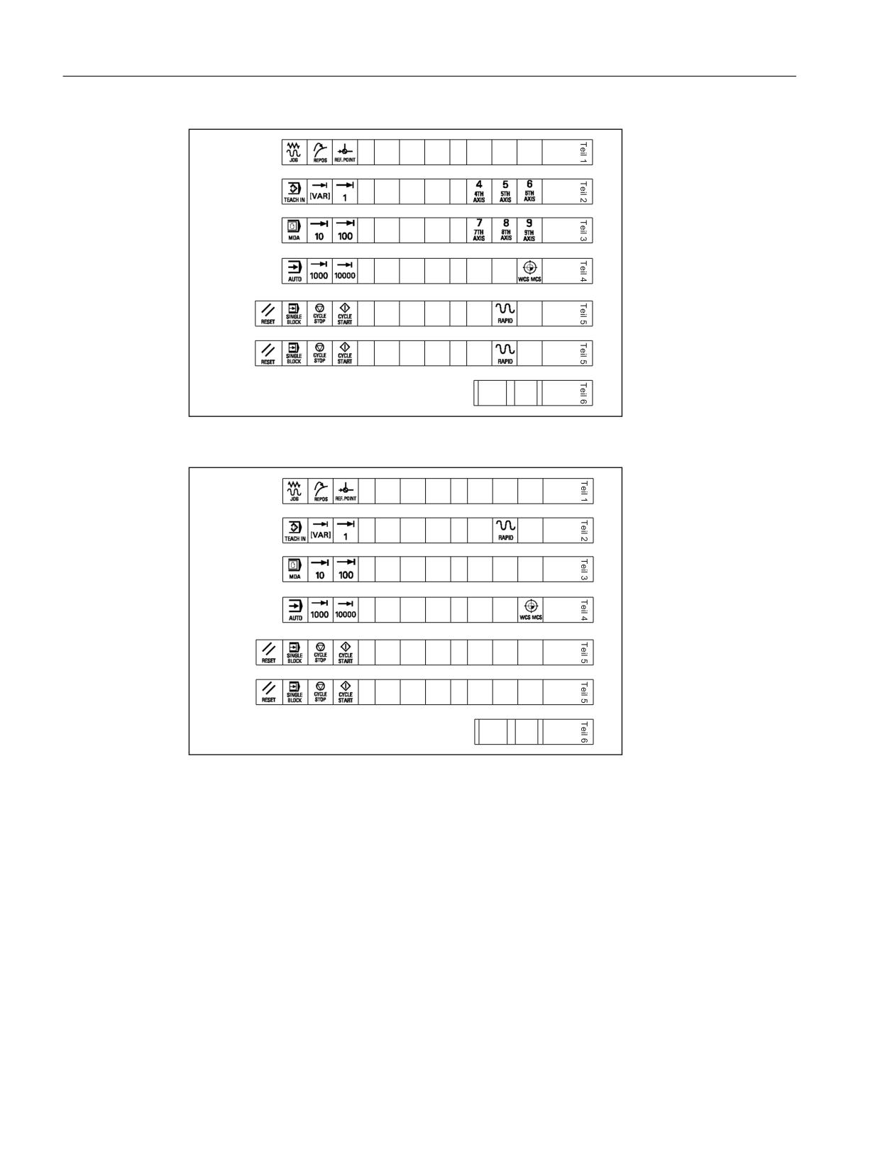
Machine control panel: MCP 483
6.9 Accessories and spare parts
;
<
=
Image 6-14 Template_M_MCP483.doc for the "Milling" version (A)
<
;
&
=
=
&
;
<
Image 6-15 Template_T_MCP483.doc for the "Turning" version (B)
Machine control panels
142
Manual, 03/2016, 6FC5397-1AP40-5BA3
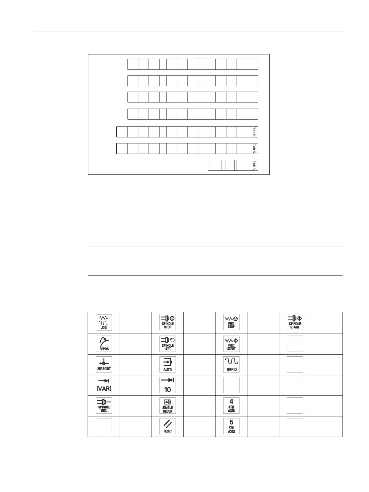
Machine control panel: MCP 483
6.9 Accessories and spare parts
Image 6-16 Template_MCP483.doc (blank template for film: Item No. A5E00205579 (C)
Within the table cells the key symbol required in each case can be copied and pasted into the
corresponding table field.
The vertical bars shown in the diagram do not appear on the printed-out labels.
The strip "Part5" is included twice so that it is available optionally as either a 1-color or 3-color
strip.
Note
Use the "Arial" font to format text. This font is comparable to the "Univers S57" font, used by
Siemens for the key labeling.
Table 6-9
Symbols.doc file (D)
7001
7013
7025
7124
7002
7014
7026
7125
&
7003
7015
7027
7126
;
7004
7016
7028
7127
=
<
7005
7017
7029
7128
=
7006
7018
7030
7129
;
Machine control panels
Manual, 03/2016, 6FC5397-1AP40-5BA3
143
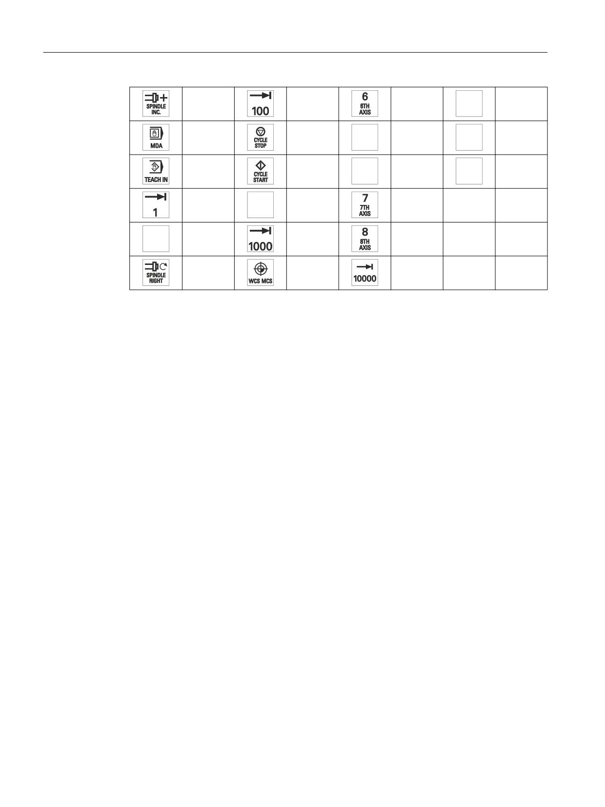
Machine control panel: MCP 483
6.9 Accessories and spare parts
7007
7019
7031
7130
<
7008
7020
7032
7131
=
7009
7021
7033
7132
&
7010
7022
7120
<
7011
7023
7121
;
7012
7024
7123
Creating your own symbols
● Printing in a vector program (e.g. Designer, Freehand, CorelDraw):
- Draw a 15 x 15 mm square, fill with the color white and give it an invisible border line.
- Place the symbol in the center of this square.
- Copy the entire image (square and symbol) and paste it into a Word document
(Symbols.doc).
● Drawing in an image editing program (e.g. Photoshop, Picture Publisher, Paint):
- Create a square area (e.g. 100 x 100 pixels) filled with the color white.
- Draw the symbol in the center of this square.
- Copy the entire image (square and symbol) and paste it into the Word document
(Symbols.doc).
Machine control panels
144
Manual, 03/2016, 6FC5397-1AP40-5BA3