SINUMERIK 840D sl Hardware. Manual (2011-2020) - page 8
Handheld Terminal HT 8
2.4 Connecting
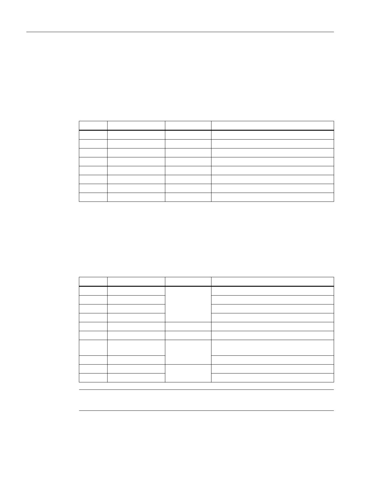
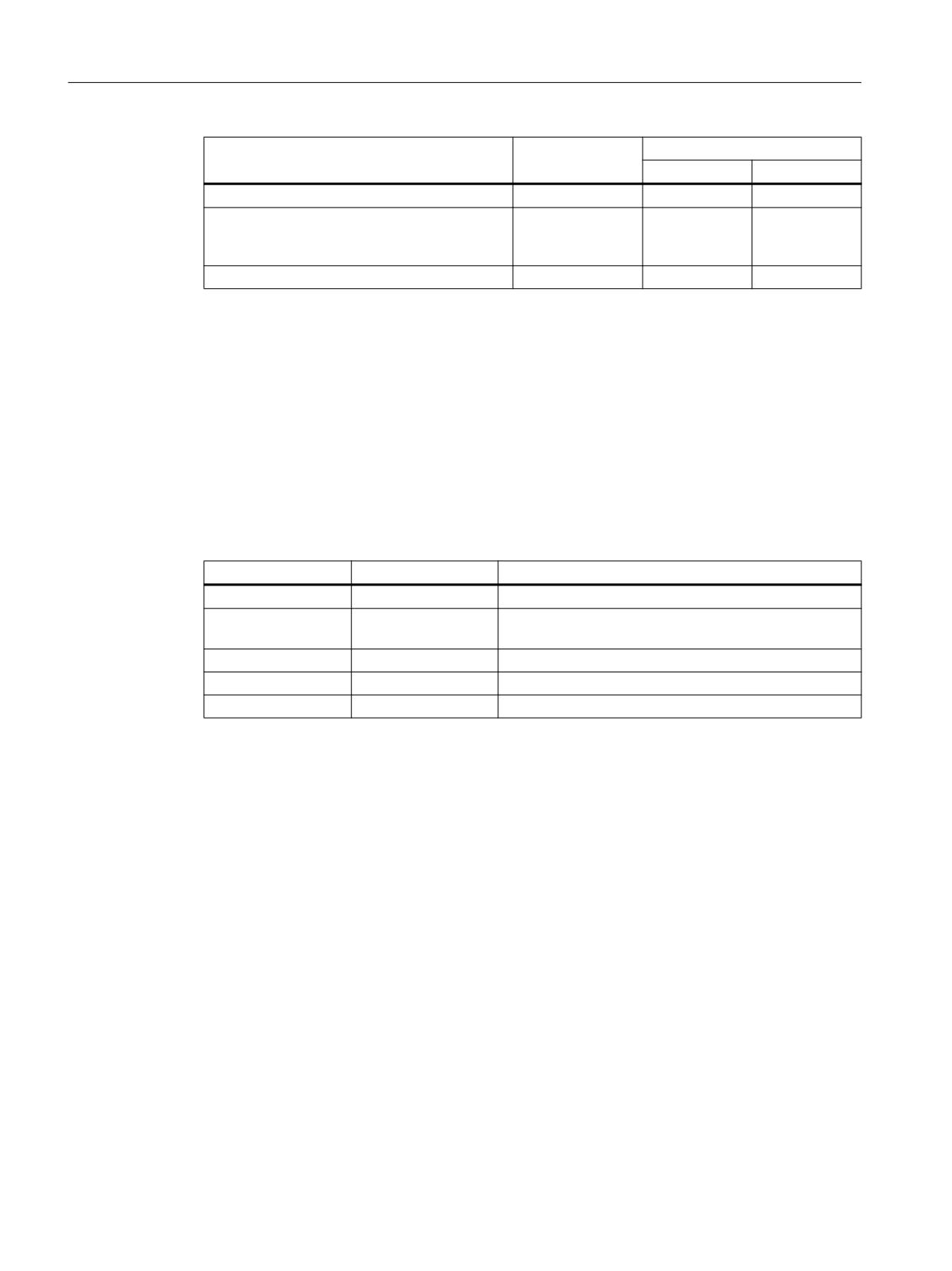
X20: Enabling buttons
Connector designa-
X20
tion:
Connector type:
8-pin Phoenix terminal
Table 2-3
Assignment of the interface enabling buttons X20
Pin
Signal name
Signal type
Meaning
1
ZUST1P
I
Electronic enabling button 1 P
2
ZUST1M
O
Electronic enabling button 1 M
3
ZUST2P
I
Electronic enabling button 2 P
4
ZUST2M
O
Electronic enabling button 2 M
5
N.C.
-
Not connected
6
N.C.
-
Not connected
7
N.C.
-
Not connected
8
N.C.
-
Not connected
X21: Emergency Stop and key-operated switch
Connector designa-
X21
tion:
Connector type:
10-pin Phoenix terminal
Table 2-4
Assignment of the interface Emergency Stop and Module Supply Voltage
Pin
Signal name
Signal type
Meaning
1
STOP23
Emergency Stop circuit
2
STOP24
Emergency Stop circuit
B
3
STOP13
Emergency Stop circuit
4
STOP14
Emergency Stop circuit
5
M
P
Ground
6
N.C.
-
-
7
IN_E9
Connected P24 (jumpered to Pin8 during opera-
P
tion)
8
P24_FILT
Filtered 24V module power supply
9
IN_E9_EXT
Feedback signal via connected P24
O
10
IN_E12_EXT
"High": Terminating connector plugged in
Note
Pins 7 and 8 must be jumpered in order to supply a handheld terminal with power.
Handheld units
92
Manual, 03/2016, 6FC5397-1AP40-5BA3
Handheld Terminal HT 8
2.4 Connecting
2.4.3.3
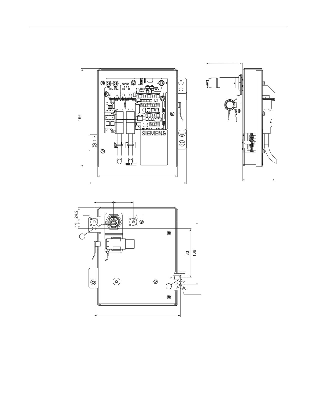
Dimension drawing
;
;
;
;
;
;
;
0
0
0
RSWLRQDO
① Elongated holes - if the module is screwed to the inside of the control cabinet
Image 2-12 Connection module Basic PN - dimension drawing for control cabinet installation
Handheld units
Manual, 03/2016, 6FC5397-1AP40-5BA3
93
Handheld Terminal HT 8
2.4 Connecting
2.4.3.4
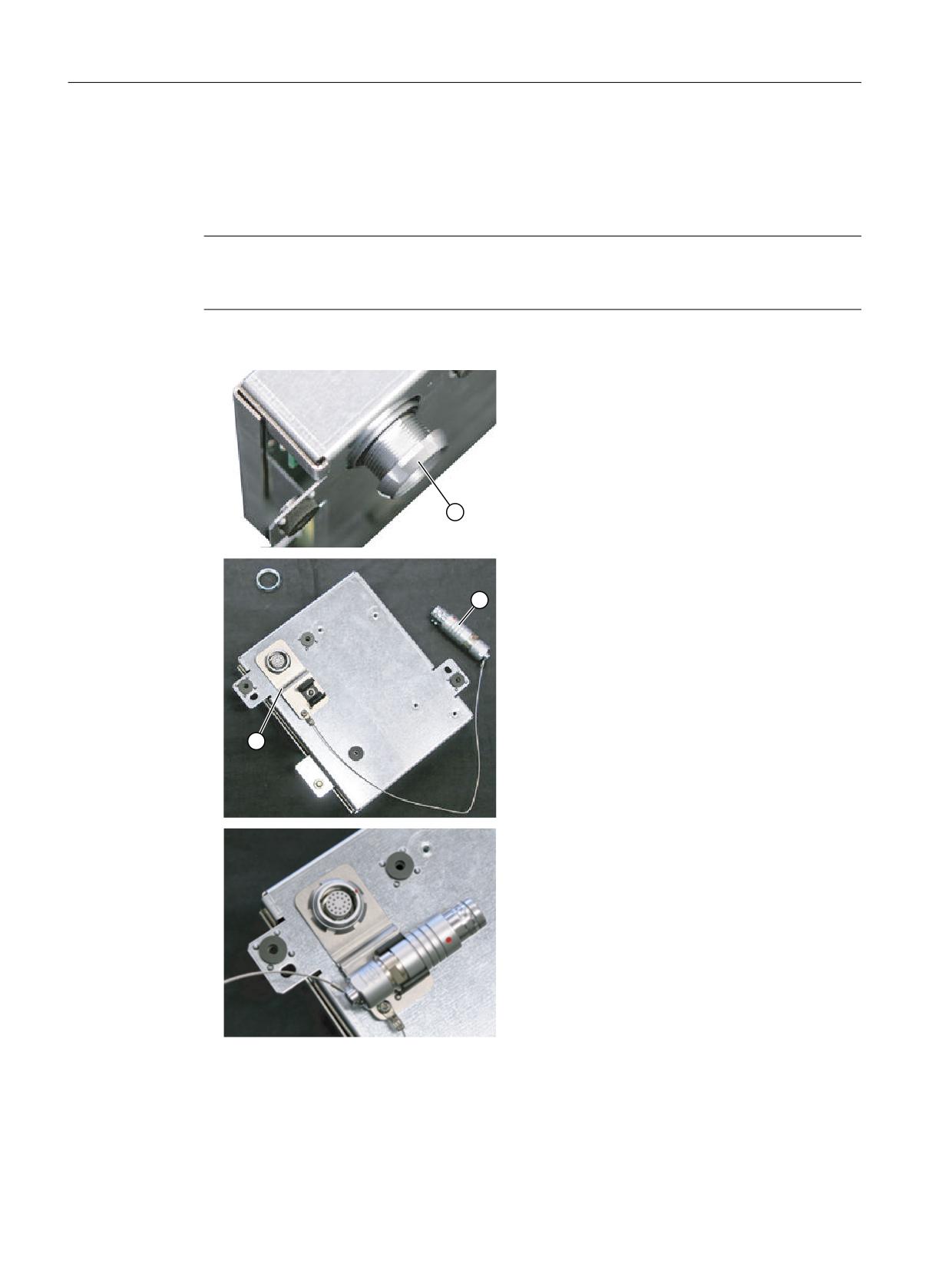
Installing the terminating connector
Procedure
Note
If you never remove the HT8 from the connection module, it is not necessary to attach the
terminating connector.
1.Unscrew the fixing nut ①.
2.Attach the bracket ① for the terminating
connector ②.
3.Tighten the retaining nut and insert the ter-
minating connector into the bracket.
Handheld units
94
Manual, 03/2016, 6FC5397-1AP40-5BA3
Handheld Terminal HT 8
2.4 Connecting
2.4.4
Connecting cable
The connecting cable is an industrial cable, can tolerate bending in-line with what is required
in practice - and is resistant to many solvents and lubricants.
The connecting cable is available in various lengths. You will find detailed information in
Section: "Accessories".
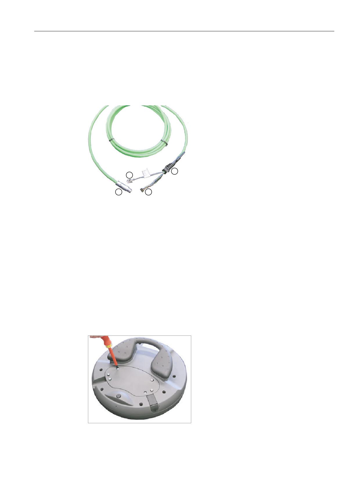
① Metallic push-pull round connector (ODU connector)
② RJ45 plug to connect to the Ethernet
③ Plug connector for enabling button, Emergency Stop, 24 V and safety signals
④ Strain relief device and kink protection
Image 2-13 Connecting cable for the HT 8
The connecting cable is connected to the HT 8 using the RJ45 plug connector ② and plug
connector ③. ODU plug connector ① is used to connect the connecting cable with the terminal
box/connecting module MPP. The tightening torque for the nut of the ODU socket is 6.5 Nm.
The HT 8 has two cable entries at the rear for connecting the cable. This makes it possible to
attach the connecting cable at either the right or left side.
One of the cable entries is closed at the factory by a connector in which a USB connection is
integrated (with IP65 cover).
Routing the connecting cable
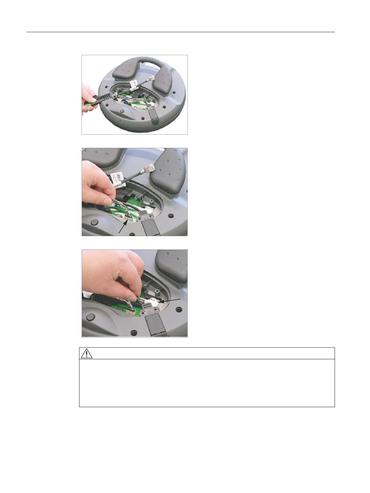
1. Open the cover by unscrewing the six PT
screws (4 x 20 mm) approximately 1 cm.
To do this, use a Phillips size 2 screwdriver.
Handheld units
Manual, 03/2016, 6FC5397-1AP40-5BA3
95
Handheld Terminal HT 8
2.4 Connecting
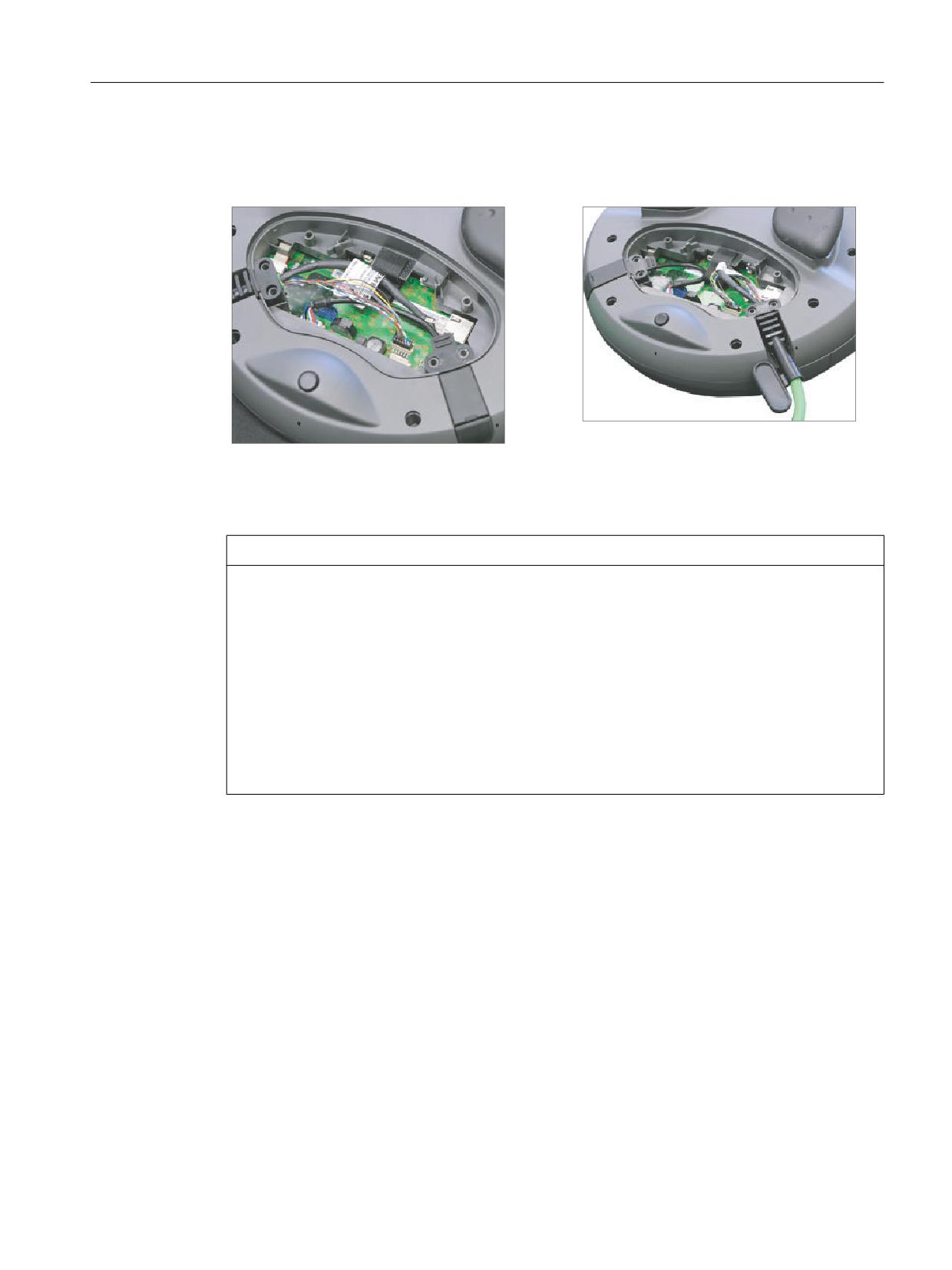
2. Insert the connecting cable in the appropriate
entry (left or right).
Press the cable downward slightly until it rests
completely on the fastening lugs
Insert a plug in the cable entry that you do not
intend to use.
3. Press the plug connector firmly into the power
supply socket.
4. Connect the RJ-45 connector to the Ethernet
socket.
WARNING
Improper installation of the cable can result in failure of the safety functions.
Please observe the following before you reattach the cover:
● Check to ensure that all of the conductors are aligned and straight and check the firm
seating of the plug connector.
● Make sure that the connecting cable sleeve is installed correctly.
Handheld units
96
Manual, 03/2016, 6FC5397-1AP40-5BA3
Handheld Terminal HT 8
2.4 Connecting
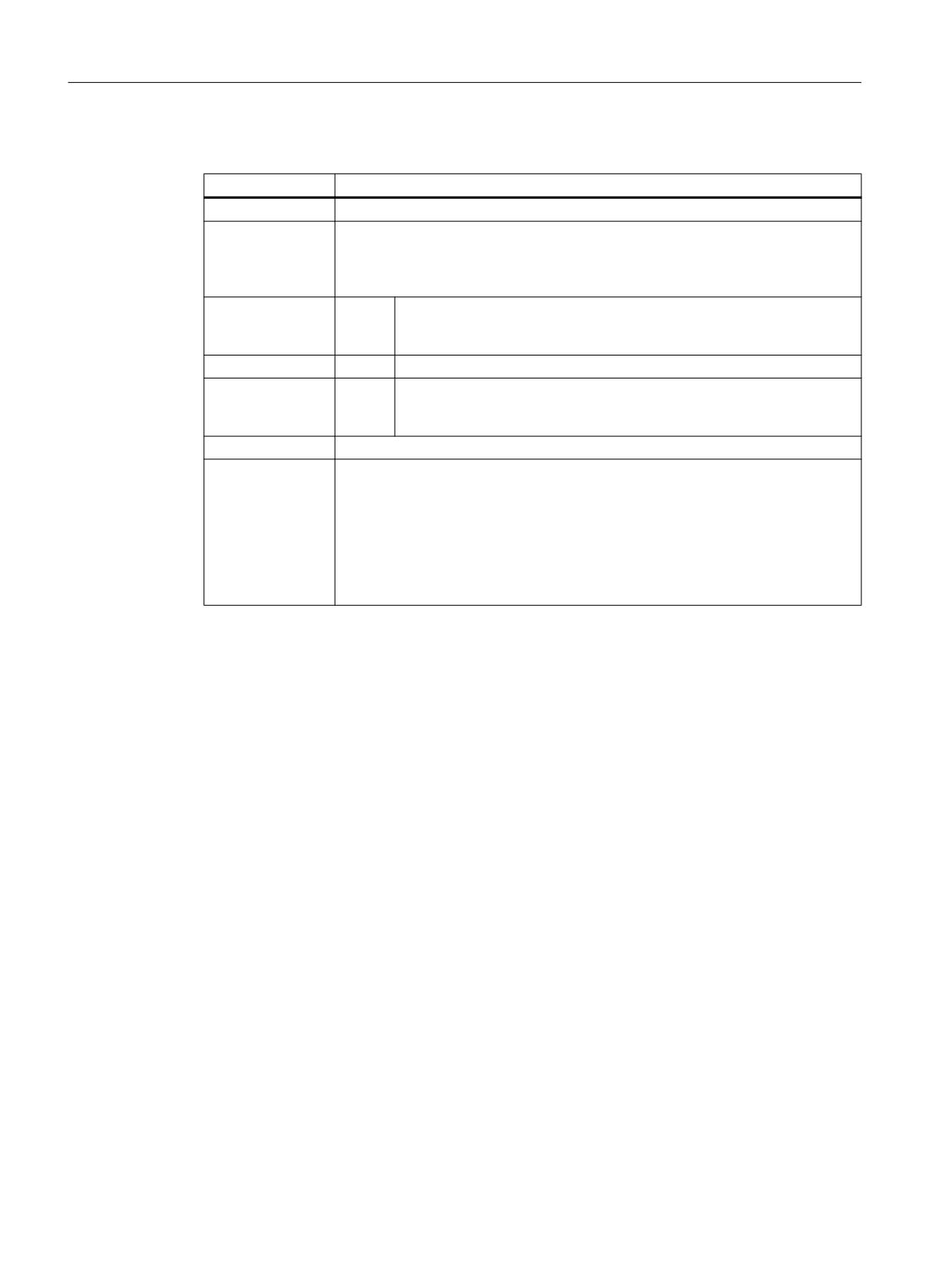
Correctly routed connecting cable
Connecting cable, left
Connecting cable, right
5.Attach the cover by tightening the six PT
screws.
NOTICE
Damage to the housing
The housing of the HT 8 is made of plastic. Therefore, the mounting hole threads cannot
handle the same amount of stress as a comparable metallic housing. Therefore, do not
exceed 0.4 to 0.5 Nm of torque when tightening the screws (also for protecting the connecting
cable).
If you use a power screwdriver, ensure the max. speed of 600 rpm is adhered to (torque: 1
Nm).
The screws of the cover may only be loosened or tightened a maximum of 20 times.
Otherwise, there is the danger that the threads might become damaged and the seal of the
housing will be compromised which could lead to failure of the device.
2.4.5
Power Supply
The HT 8 is supplied with power via the terminal box/connection module.
The input voltage range is designed for +24 VDC.
For further details, see: "General notes and interconnection" → "Operational planning"→
"General electrical conditions" → "Power supply".
Handheld units
Manual, 03/2016, 6FC5397-1AP40-5BA3
97
Handheld Terminal HT 8
2.5 Commissioning
2.4.6
Unplugging/plugging during operation
The ability to detect a connected HT 8 in the PLC
1. HW solution:
Interface X7 of the Basic PN connection module signals "HT 8 Present" at pin 1 for the
"active" connection module (see interfaces (Page 89)).
If the connection module is "inactive", this signal is not set.
This makes the "active" connection module detectable in the PLC by wiring the above-
mentioned pins of all connection modules to digital I/Os on PLC I/O modules.
2. Permanently configured MCPs / HT 8 connected to one control:
If there are only permanently configured MCPs / HT 8 that a control, removal of the MCP
or HT 8 triggers the PLC alarm "400260 Machine Control Panel failed".
Based on this, an "active" or "inactive" MCP / HT 8 in the PLC can be detected.
The failure of an MCP / HT 8 is, however, only detected in the PLC if max. 2 MCP / HT 8
are permanently configured and no MCP switchover using FB9 (e.g. triggered when
operator focus is switched at the operator panel).
Note
Removing an HT 8 where the integrated machine control panel is active
Depending at which interface in the PLC (FB1: MCP1 or MCP2) the HT 8 is configured, before
removing the HT 8, the transfer of the machine control panel signals must be stopped.
This is possible as direct axis via data block DB7 (instance of the FB1).
To do this, set the corresponding interface signal to "true":
●
1. Interface: DB7.DBX62.1 (MCP1Stop)
●
2. Interface: DB7.DBX62.2 (MCP2Stop)
If the machine control panel signals are not stopped, then the message "400260 machine
control panel x failed" is displayed at the user interface:
Transfer of the machine control panel signals can be restarted after inserting the HT 8. To do
this, set e.g. the PLC interface signal DB7.DBX62.1 (MCP1Stop) to "false".
2.5
Commissioning
2.5.1
SINUMERIK Operate
2.5.1.1
Activating/deactivating the virtual keyboard
The virtual keyboard is configured in the file "slguiconfig.ini".
Handheld units
98
Manual, 03/2016, 6FC5397-1AP40-5BA3
Handheld Terminal HT 8
2.5 Commissioning
Procedure
1. Copy the "slguiconfig.ini" file from the folder
/siemens/sinumerik/hmi/template/cfg.
2. Paste the copy of the file into the following directory:
/oem/sinumerik/hmi/cfg or /user/sinumerik/hmi/cfg.
3. Open the file in the editor.
4. To activate or deactivate the keyboard, make the following settings:
- Activating the virtual keyboard:
In the section [TouchPanel], EnableTouch = true
In the section [Keyboard], EnableVirtualKeyBoard = true
- Deactivating the virtual keyboard:
In the section [TouchPanel], EnableTouch = true
In the section [Keyboard], EnableVirtualKeyBoard = false
5. Double click in the input field to display the keyboard.
2.5.1.2
Configuring the traversing keys
The traversing keys of the HT 8 are not labeled as their type of action is not predefined. The
labeling of the traversing keys should adapt dynamically to the type of action of the keys. To
recognize the type of action of the traversing keys, they are shown within the display in the
vertical softkey area.
The menu of the traversing keys consists of two vertical rows each with eight keys so that up
to 16 texts can be configured. The top and bottom traversing key row remain empty and can
be assigned other functions.
The following data can be displayed:
● Machine axis name
● Alias name for machine axis
● Any language-dependent text
● Symbol
The following user-specific files are required. You can use the sample files as template:
File
Meaning
"sljkconfig.ini" configuration file
File in which the traversing keys are configured.
Text file "oem_sljk_xxx.ts"
File for labeling traversing keys in a foreign language, xxx =
language code
Handheld units
Manual, 03/2016, 6FC5397-1AP40-5BA3
99
Handheld Terminal HT 8
2.5 Commissioning
"sljkconfig.ini" configuration file
Entries
Meaning
[State_1]
Labeling type - changed via the PLC.
ParamText_x_y
Text of the traversing key that is made up of parameters.
Two-line labeling is possible, whereby max. five characters are possible per line.
x: Specifies the position of the key within the row (2 to 7).
y: Specifies the key row (1 or 2).
%m1
The machine axis name of the first axis is referenced and displayed as
text. The current active axis number is read out from data block DB10.
The name from the machine data is determined via this index.
%n
Defines the position in the text for the line break.
%a1
The alias axis name of the first axis is referenced and displayed as text.
The current active axis number is read out from data block DB10. The
name from the "oem_sljk_eng.ts" text file is determined via this index.
TextId_x_y
Text of the traversing key that is read from the text file (target language text).
Picture_x_y
File name of the icon to be displayed.
The files with the icons must be located in the following directories: /oem/sinumerik/
hmi/ico and
depending on the resolution of the subdirectories:
/ico640
/ico800
/ico1024
/ico1280
Procedure
1. Copy the "sljkconfig.ini" configuration file from the folder
/siemens/sinumerik/hmi/template/cfg
2. Place the copy into the folder /oem/sinumerik/hmi/cfg
or /user/sinumerik/hmi/cfg
3. Open the copy in the Editor and define the traversing key labeling.
Example of a "sljkconfig.ini" configuration file
12 axes are defined in the example, with text for softkey 1 and softkey 2, as well as an image
on softkey 3 and softkey 4.
[Settings]
FileType = INI
; A few examples for further configuration options
; Alias names of machine-axes (%a1, %a2, etc.), from oem_sljk_deu.ts
(example)
[State_1]
TextId_1_1 = OEM_JK_TEXT_1
Handheld units
100
Manual, 03/2016, 6FC5397-1AP40-5BA3

Handheld Terminal HT 8
2.5 Commissioning
TextId_1_2 = OEM_JK_TEXT_2
ParamText_2_1 = %a1%n-
ParamText_2_2 = %a1%n+
ParamText_3_1 = %a2%n-
ParamText_3_2 = %a2%n+
ParamText_4_1 = %a3%n-
ParamText_4_2 = %a3%n+
ParamText_5_1 = %a4%n-
ParamText_5_2 = %a4%n+
ParamText_6_1 = %a5%n-
ParamText_6_2 = %a5%n+
ParamText_7_1 = %a6%n-
ParamText_7_2 = %a6%n+
Picture_8_1 = AlarmCancel.png
Picture_8_2 = AlarmNCReset.png
"oem_sljk_eng.ts" text file
Entries
Meaning
name
Freely selectable name of the text context.
In the text file template, the name of the text context is "SIJkLabels" and stands for the
traversing key labeling (solution line jog key labels). This identifier is already stored in
the configuration file.
source
Traversing key identifier of the respective axis. This text ID is referenced in the "sljkcon-
fig.ini" configuration file with the "TextId_2_1".
The text IDs for the alias names (JK_AXISNAME_2 to JK_AXISNAME_7) must not be
changed.
translation
Input of the foreign language text for the axis specified in <source>.
Language code in file names "xxx"
Language
Language code
German
deu
English
eng
French
fra
Spanish
esp
Italian
ita
Chinese
chs
Handheld units
Manual, 03/2016, 6FC5397-1AP40-5BA3
101
Handheld Terminal HT 8
2.5 Commissioning
Procedure
1. You can copy the sample file " oem_sljk_deu.ts" from the following directory: /siemens/
sinumerik/hmi/template/lng.
2. Store or create the file in the /oem/sinumerik/hmi/lng or
/user/sinumerik/hmi/lng directory.
3. Give the file a name, e.g. for German texts: "sljk_deu.ts".
If you wish to set-up the labeling for additional languages, a separate file must be created
for each language. Save the file with the appropriate language code in the file name. To
do this, use the language codes specified above.
4. Open the file and in the <message> and </message> area, define the labeling.
5. Restart the HMI.
In order that the labeling is displayed during the program runtime, the file must be converted
into a binary format. This conversion is only executed when the HMI powers up.
Example of a text file "sljk_deu.ts"
12 axes are defined in the example, with text for softkey 1 (SF1) and softkey 2 (SF2):
<?xml version="1.0" encoding="utf-8"?>
<!DOCTYPE TS>
<TS>
<context>
<name>SlJkLabels</name>
<!-- Alias names for machine axis (%a1, %a2, etc.) -->
<!-- Do not change the text ID (JK_AXISNAME_1, etc.) -->
<message>
<source>JK_AXISNAME_1</source>
<translation>X</translation>
</message>
<message>
<source>JK_AXISNAME_2</source>
<translation>Y</translation>
</message>
<message>
<source>JK_AXISNAME_3</source>
<translation>Z</translation>
</message>
<message>
<source>JK_AXISNAME_4</source>
<translation>A</translation>
</message>
<message>
<source>JK_AXISNAME_5</source>
<translation>B</translation>
Handheld units
102
Manual, 03/2016, 6FC5397-1AP40-5BA3
Handheld Terminal HT 8
2.5 Commissioning
</message>
<message>
<source>JK_AXISNAME_6</source>
<translation>C</translation>
</message>
<message>
<source>JK_AXISNAME_7</source>
<translation>U</translation>
</message>
<message>
<source>JK_AXISNAME_8</source>
<translation>V</translation>
</message>
<message>
<source>JK_AXISNAME_9</source>
<translation>W</translation>
</message>
<message>
<source>JK_AXISNAME_10</source>
<translation>UV1</translation>
</message>
<message>
<source>JK_AXISNAME_11</source>
<translation>UV2</translation>
</message>
<message>
<source>JK_AXISNAME_12</source>
<translation>UV3</translation>
</message>
<!-- User defined language dependent text (example) -->
<message>
<source>OEM_JK_TEXT_1</source>
<translation>SF1</translation>
</message>
<message>
<source>OEM_JK_TEXT_2</source>
<translation>SF2</translation>
</message>
</TS>
Handheld units
Manual, 03/2016, 6FC5397-1AP40-5BA3
103

Handheld Terminal HT 8
2.5 Commissioning
2.5.1.3
Configuring user-specific key labeling
Labeling the keys for the HT 8
The texts of the CPF menu (CPF: Control Panel Function) for the HT 8 can be labeled with
your own texts in the particular language of the country.
The texts are created in the "slck_xxx.ts" file.
"xxx" = language code for the corresponding language-specific labeling.
You can create and edit this file using the HMI or also externally on a PC.
Note
If you wish to create or edit the file on a PC, use an editor that supports UTF-8 coding.
Language code in file names "xxx"
Language
Language code
German
deu
English
eng
French
fra
Spanish
esp
Italian
ita
Chinese
chs
Creating key labeling
Tag
Meaning
source
Designation for the user softkey. "SK_USERKEY1" to "SK_USERKEY16" are possi-
ble, whereby the names may not be changed.
comment
User-specific description of the key assignment.
translation
Text that should be shown on the key.
● A maximum of 10 characters are possible per line.
●
2-line labeling is possible, whereby the line break is set using "%n".
remark
Remark for key assignment.
chars
Number of characters. A maximum of 10 characters per line are possible.
lines
Number of lines. 2 lines are possible.
Procedure
1. You can copy the sample file " oem_slck_deu.ts" from the following directory: /siemens/
sinumerik/hmi/template/lng.
2. Store or create the file in the /oem/sinumerik/hmi/lng or
/user/sinumerik/hmi/lng directory.
Handheld units
104
Manual, 03/2016, 6FC5397-1AP40-5BA3
Handheld Terminal HT 8
2.5 Commissioning
3. Give the file a name, e.g. for German texts: "slck_deu.ts".
If you wish to create the key labeling for additional languages, then a separate file must be
created for each language. Save the file with the appropriate language code in the file name.
To do this, use the language codes specified above.
4. Open the file and in the <message> and </message> area, define the key labeling.
5. Restart the HMI.
In order that the key labeling is displayed during the program runtime, the file must be
converted into a binary format. This conversion is only executed when the HMI powers up.
Example of a key label
<!DOCTYPE TS><TS>
<context>
<name>SlCkDialog</name
<message>
<source>SK_USERKEY1</source>
<comment></comment>
<translation>U1</translation>
<remark>User key 1</remark>
<chars>10</chars>
<lines>2</lines>
<languageIndependent>true</languageIndependent>
</message>
<message>
<source>SK_USERKEY2</source>
<comment></comment>
<translation>U2</translation>
<remark>User key 2</remark>
<chars>10</chars>
<lines>2</lines>
<languageIndependent>true</languageIndependent>
</message>
<message>
</message>
</context>
</TS>
Handheld units
Manual, 03/2016, 6FC5397-1AP40-5BA3
105
Handheld Terminal HT 8
2.5 Commissioning
2.5.1.4
Configuring the function display at user-specific keys (U keys)
Function
Active functions can be displayed at the configurable user keys via the PLC. For instance,
small LEDs can be emulated on the softkeys.
You configure the function in the "slckcpf.ini" file.
Interface signals
The PLC bits are in the output image of the PLC-HT 8 interface and are analog to those in the
input image.
Signals to the MCP1 (or MCP2)
Interface PLC → HT 8
Byte
Bit 7
Bit 6
Bit 5
Bit 4
Bit 3
Bit 2
Bit 1
Bit 0
AB n + 1
U4
U3
U2
U1
AB n + 4
U9
U10
U11
U12
U13
U14
U15
U16
AB n + 5
U8
U7
U6
U5
Adapt the display in the "slckcpf.ini" file
Section
Description
UserKeyLEDIcon
Name of the icon file.
Standard entry: led_green.png
OFF
Deactivates the icon display.
PRESSED
Displays the active functions by pressing
down the softkey.
UserKeyLEDIconAlignment
Specifies the position of the icon.
Standard position: AlignLeft | AlignTop
Horizontal and vertical alignments can be combined. The two
names are separated by the "|" character.
The following alignments are possible:
AlignLeft
Left
AlignRight
Right
AlignHCenter
Horizontal, center
AlignTop
Top
AlignBottom
Bottom
AlignVCenter
Vertical, center
UserKeyLEDMap
Specifies the start address of the output image.
Entries can be made in the following form: "DBx.DBBy", "ABx",
"MBx".
Default setting: The start address is determined using
DB7 MCP1Out (or MCP2Out).
Handheld units
106
Manual, 03/2016, 6FC5397-1AP40-5BA3

Handheld Terminal HT 8
2.5 Commissioning
Section
Description
U1LED ... U16LED
The status bit address can be defined - different from the output
VarIncLED
image - using these entries.
Note: The offsets from the HT 8 output image, for one or several
SBLLED
softkeys, are not taken into consideration.
WCSLED
showVarIncLED
true
When the increment mode is active, the icon is also
displayed on the "[VAR]" softkey.
false
The icon is not displayed.
showSBLLED
true
When the SingleBlock mode is active, then the icon
is also displayed on the "Single Block" softkey.
false
The icon is not displayed.
showWCSLED
true
When the SingleBlock mode is active, then the icon
is also displayed on the "Single Block" softkey.
false
The icon is not displayed.
1. You can copy the sample file "slckcpf.ini" from the following directory: /siemens/sinumerik/
hmi/template/cfg
2. Store the file in the /oem/sinumerik/hmi/cfg or /user/sinumerik/hmi/cfg directory.
3. If you use your own icon, then locate it together with the corresponding resolution for HT 8
directory: /oem/sinumerik/hmi/ico/ico640 or /user/sinumerik/hmi/ico/ico640.
4. Open the file and make the appropriate settings.
Sample file "slckcpf.ini"
Template for the configuration of the
; HT8 control panel function menu
;
; To activate the settings remove the
; commentary ';' at the beginning of the line
;; Display settings of the user key softkey leds
[UserKeyLED]
; Filename of the LED icon
;UserKeyLEDIcon = led_green.png
; Alignment of the LED icon
;UserKeyLEDIconAlignment= AlignLeft | AlignTop
; Use following led map start address instead of calculating
DB7.MCP1Out
;UserKeyLEDMap = AB0
Handheld units
Manual, 03/2016, 6FC5397-1AP40-5BA3
107
Handheld Terminal HT 8
2.5 Commissioning
; Use the following settings to use this status bits instead of the
led map for a specific sk
;U1LED=/channel/parameter/R[U1,1]
;
;U16LED=/channel/parameter/R[U1,16]
;VarIncLED = DB11.DBX8.5
;SBLLED = DB21.DBX0.4
;WCSLED = DB19.DBX0.7
; Show a LED for the var inc sk
;showVarIncLED = true
; Show a LED for the var single block sk
;showSBLLED = true
; Show a LED for the var wcs/mcs sk
;showWCSLED = true
2.5.1.5
Troubleshooting
If errors occur while booting, an appropriate message is displayed.
For further information, see Chapter "General information and networking" → "Networking" →
"Diagnostics and service".
2.5.2
HMI Advanced
2.5.2.1
Configuring the traversing keys of the HT 8
Prerequisite
In order to display or skip the labeling of the traversing keys, the HT 8 must have user
authorization.
Parameterizing the MCP signals of the HT 8 in the PLC
HT 8-relevant blocks in the PLC program are FB 1 for HT 8/PLC communication and FC 26
for NCK/PLC communication.
Handheld units
108
Manual, 03/2016, 6FC5397-1AP40-5BA3
Handheld Terminal HT 8
2.5 Commissioning
Display/skip the labeling of traversing keys on HT 8
In order to inscribe the traversing keys, the names of the first six axes are established from
the machine data 10000: AXCONF_MACHAX_NAME_TAB (indexed using DB 10, bytes 8 to
13).
The LED image of HT 8 serves as the interface for displaying the labeling by the PLC. The
PLC sets a bit in the LED image of the HT 8 to display or skip the traversing keys:
Signal AB n+6 bit 7 = 1 for displaying
Signal AB n+6 bit 7 = 0 for skipping
Note
To ensure that the labeling of the traversing keys is displayed correctly, the names of the axes
must not exceed 10 characters.
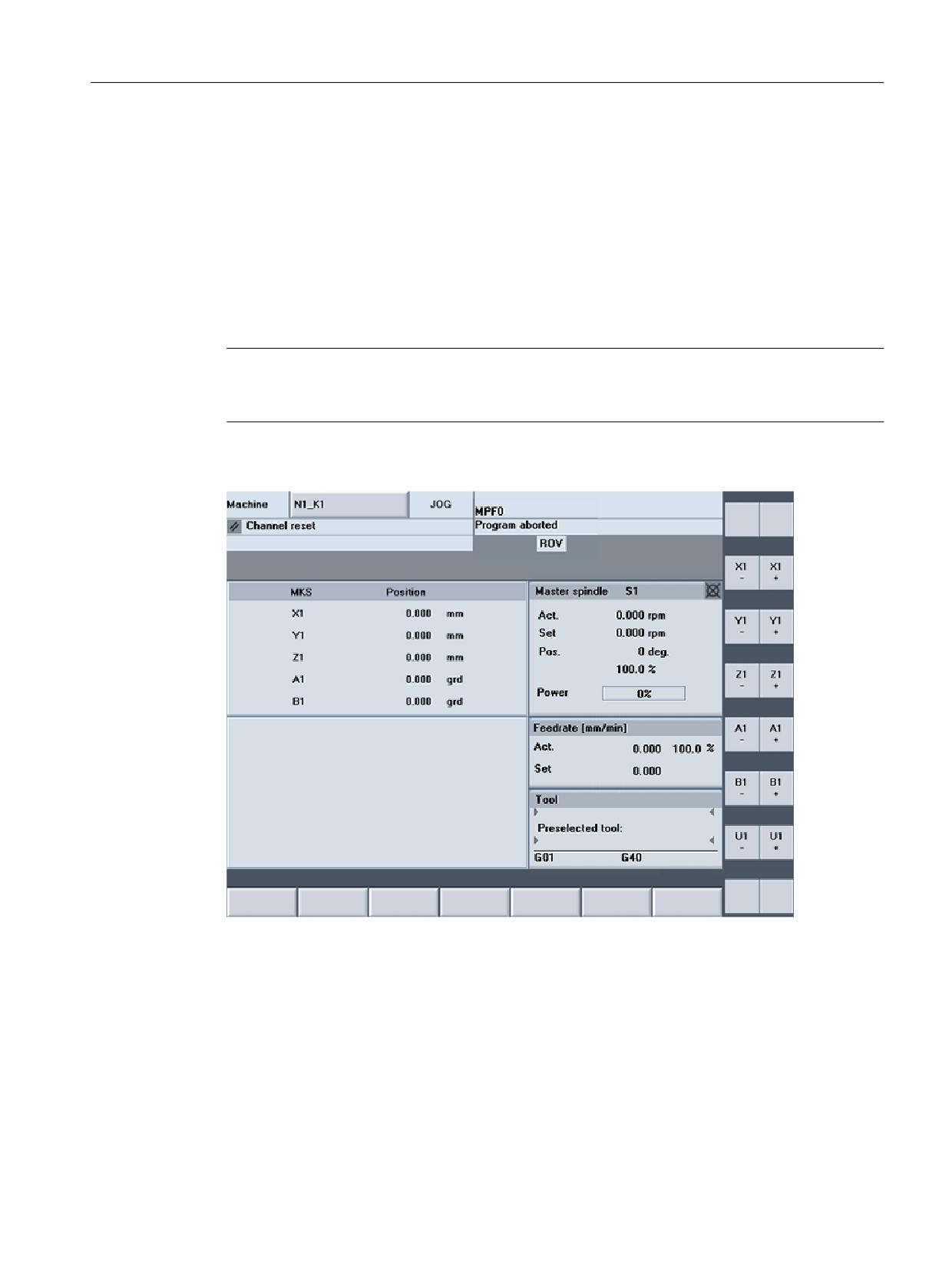
Example with labeling of traversing axes displayed:
Image 2-14 Traversing axes displayed
Acknowledging display/skipping by HMI on PLC
The HMI communicates to the PLC whether the traversing keys are displayed or hidden. This
is done using bit 7 in byte 72 of DB 10:
Displayed:
DB10.DBX72.7 = 1
Skipped:
DB10.DBX72.7 = 0
Handheld units
Manual, 03/2016, 6FC5397-1AP40-5BA3
109
Handheld Terminal HT 8
2.5 Commissioning
User keys
The user keys (the 2 keys at the top and bottom) can be assigned in any way. User keys, which
can be used to trigger a wide range of machine functions, are evaluated directly by the PLC
program.
See also:
You will find additional information on the HT 8 in:
● Function Manual Basic Functions, basic PLC program (P3 sl)
● You will find a description of the machine data in:
Detailed Machine Data Description
● Operating Manual HMI-Advanced
2.5.2.2
Configuring user-specific key labeling
Labeling the keys for the HT 8
The texts of the CPF menu (CPF: Control Panel Function) for the HT 8 and the traversing keys
can be labeled by the user with his own texts in his specific language.
A language-dependent file ht8_xx.ini is provided in directory \mmc2\language for this purpose.
Only edit a copy of this original file and place this copy in one of the following directories:
● user\language
● oem\language
● addon\language
There are two sections in file ht8_xx.ini; one for the CPF menu ( [CPFSoftkeyText] ) and one
for a maximum of 31 traversing keys ( [AxiskeyText] ). With no entry (e.g. U2="") or for the
value <empty> (e.g. U2=<empty>) no labeling text is displayed on a softkey or on a traversing
key (-/+).
● The entries for the CPF keys are pre-assigned as standard with U1 ... U16.
● The texts for the traversing keys are not activated as default setting for the following reason:
If no traversing key text is read, the name is determined from the machine data - with the
axis number as index - and correspondingly output: ("/ACC/NC_TEA/
$MN_AXCONF_MACHAX_NAME_TAB[" & chAxisNbr(k%) & "]", chAxisName(k%)
Note
It is not possible to combine the labeling texts - e.g. a part of the name from the INI file and
another part from the machine data.
Handheld units
110
Manual, 03/2016, 6FC5397-1AP40-5BA3
Handheld Terminal HT 8
2.5 Commissioning
Configuration file
Example of a key labeling (ht8_xx.ini):
[CPFSoftkeyText]
U1 =
"User%nKey 1"
;
2*10
→ Text is two lines due to %n
U2 =
"UserKey 2"
;
2*10 characters
U3 =
"UserKey 3"
;
2*10 characters
U4 =
"UserKey 4"
;
2*10 characters
U5 =
"UserKey 5"
;
2*10 characters
U6 =
"UserKey 6"
;
2*10 characters
U7 =
"UserKey 7"
;
2*10 characters
U8 =
"UserKey 8"
;
2*10 characters
U9 =
"ETC-UKey 9"
;
2*10 characters
U10 =
"ETC-UKey 10"
;
2*10 characters
U11 =
"ETC-UKey 11"
;
2*10 characters
U12 =
"ETC-UKey 12"
;
2*10 characters
U13 = "ETC-UKey 13"
;
2*10 characters
U14 = "ETC-UKey 14"
;
2*10 characters
U15 = "ETC-UKey 15"
;
2*10 characters
U16 = "ETC-UKey 16"
;
2*10 characters
[AxiskeyText]
;
here, a line break is obtained with
2 blanks.
SF1 = "sf_1"
;
2*10 characters
SF2 = <EMPTY>
;
2*10 characters
SF3 = "sf_3"
;
2*10 characters
SF4 = "sf_4"
;
2*10 characters
AX1 = "Wx"
;
2*5 characters
AX2 = "Xx"
;
2*5 characters
AX3 = <empty>
;
2*5
No text is displayed on the
traversing key (-/+).
AX4 = <EMPTY>
;
2*5 characters
AX5 = "Yx"
;
2*5 characters
AX6 = "Zx"
;
2*5 characters
Traversing keys
As standard, keys for axes 1 to 6 are displayed. If the 2nd vertical softkey is pressed in the
CPF menu (change over traversing keys), then the next time that the traversing keys are
displayed, keys 7 to 12 are displayed; after pressing the 2nd vertical softkey in the CPF menu,
then axis keys 1 to 6 are displayed again, etc.
Handheld units
Manual, 03/2016, 6FC5397-1AP40-5BA3
111
Handheld Terminal HT 8
2.6 Maintenance and Service
Note
Switch off CPF menu
The CPF_Disabled entry is evaluated in the [CONTROL] section of the MMC.INI configuration
file: If the value = 1, the CPF menu will not be displayed.
2.6
Maintenance and Service
Cleaning the device
Use a soft cloth moistened either with water or a mild cleaning agent to clean the housing,
display and operator control elements of the HT 8.
Checking the device
In order to prevent foreign bodies or liquids entering the HT 8, regularly check the device
● that all the housing screws are in place and tight
● for damage to the housing
● for damage to the cable cover or cable entry
Protect the device from environmental effects
Protect the HT 8 against
● direct solar radiation and heat sources
● mechanical vibration and shock
● dust
● moisture, and
● strong magnetic fields
Checking the emergency stop button and the enabling button
Check the emergency stop button regularly to ensure that it functions correctly.
Check the enabling button regularly to ensure that it functions correctly in the enable and panic
position.
WARNING
Danger of death caused by damaged HT 8
Immediately check the functioning of the emergency stop button and the enabling button if
the device was subject to significant shock (e.g. because it was dropped).
Handheld units
112
Manual, 03/2016, 6FC5397-1AP40-5BA3
Handheld Terminal HT 8
2.7 Technical data
2.7
Technical data
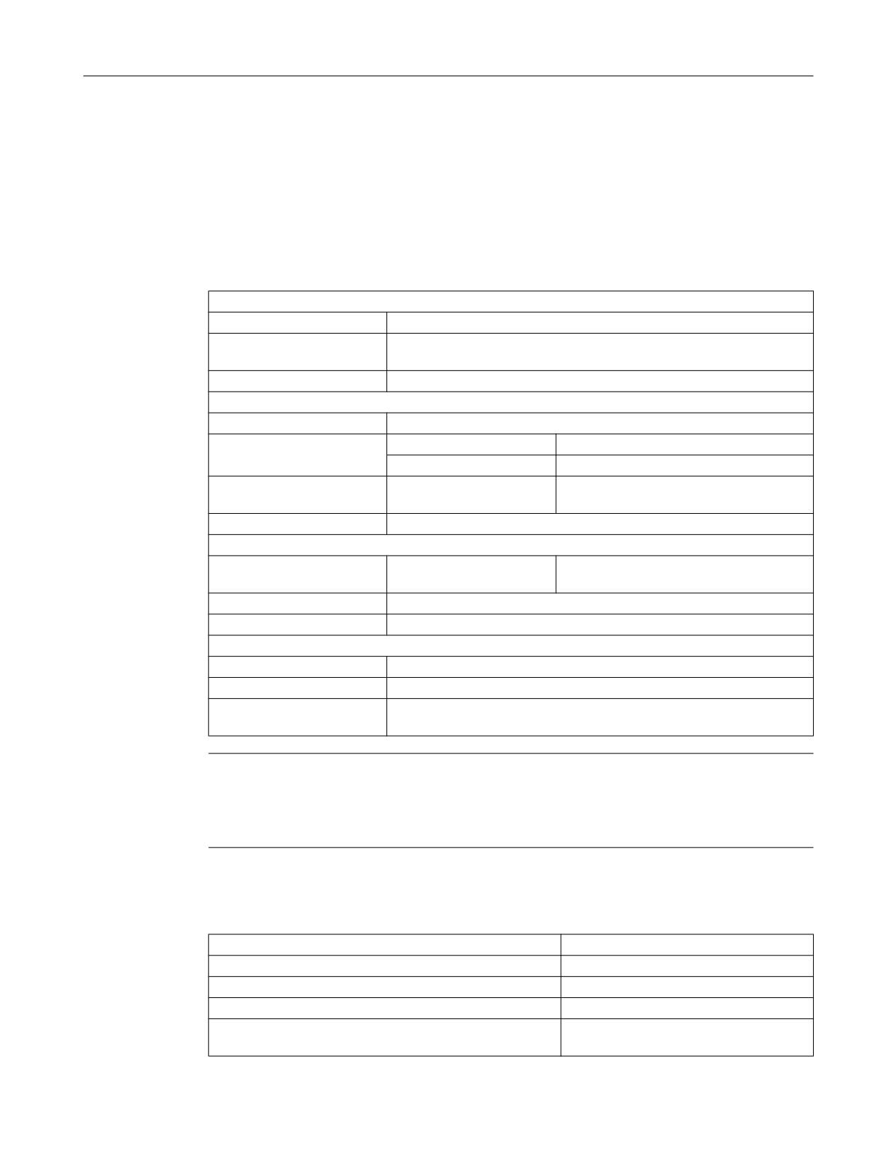
2.7.1
Handheld Terminal HT 8
HT 8 handheld terminal
Safety
Safety class
III according to EN 61131-2 / EN 50178
Degree of protection accord-
IP65
ing to EN 60529
Approvals
CE / cULus
Electrical data
Input voltage
24 V DC
Current carrying capacity
Enabling button:
10 - 250 mA / 2-channel, 3-stage
Emergency Stop button:
10 - 1000 mA / 2-channel
Max. current carrying capaci-
USB interface:
100 mA
ty
Power consumption, max.
Approx. 13 W
Mechanical data
Dimensions
Diameter:
Height:
Approx. 290 mm
Approx. 126 mm
Weight
Approx. 1730 g
Fall height, max.
1.20 m
Display
Size
7.5" TFT
Resolution
640 x 480 pixels
Service life
At ambient temperatures of > 40º C and long periods of non-use, it is
advisable to activate the screen saver function.
Note
Information about the climatic and mechanical environmental conditions is contained in the
associated section under:
"General notes and interconnection" → "Operational planning".
Emergency Stop button
Rated voltage
24 V DC
Current rating, max.
1 A
Current rating, min.
10 mA
Switching capacity
DC 13 according to EN 60947-5-1
Conditional rated short-circuit current
1000 A, 6A gL/gG according to EN
60947-5-1
Handheld units
Manual, 03/2016, 6FC5397-1AP40-5BA3
113
Handheld Terminal HT 8
2.7 Technical data
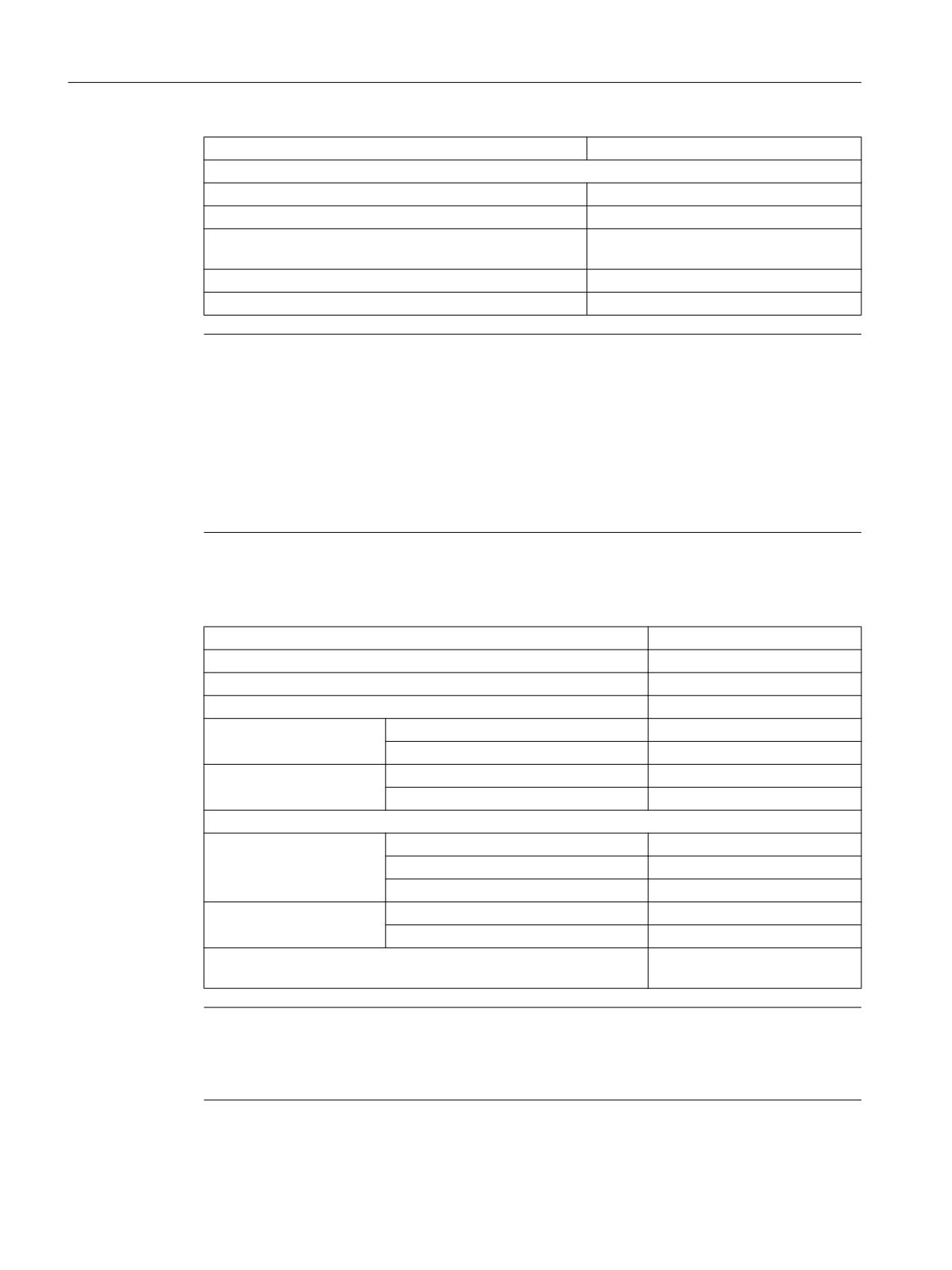
B10d (if no PN terminal box used)
100 000
When the PN Plus connection box is used:
PFHd
1.01 * 10-7
Service life
20 years
Forced dormant error detection interval (mechanical actua-
1 year
tion to the test the emergency stop)
Category
3
Performance Level
PL d
Note
The quantitative assessment of the emergency stop safety function must be based on the
B10d value corresponding to the used standards (e.g. ISO 13849-1) under consideration of the
respective application (frequency of the actuation, service life, diagnostics by the evaluation
unit, etc.). The B10d value only applies when the technical properties of the emergency stop
button are taken into account.
When using the PN Plus terminal box, the specified failure probability (PFHd) must be taken
into account. This value only applies when the technical properties of the PN Plus terminal box
and the quantitative conditions specified here (e.g. service life) are observed.
Enabling button
2-circuit , 3-stage
Supply voltage
24 V DC
Current rating, max.:
250 mA
Current rating, min.:
0 A
Operating cycles
Switch position 2
105
Switch position 3
5 * 104
Actuation forces
From switch position 1 to 2, typically
3 N
From switch position 2 to 3, typically
17 N
Functional safety
EN ISO 13849-1:2008
Category
4
Performance Level (PL)
PL e
Proof test interval (operating duration)
20 years
EN 61508
Safety Integrity Level (SIL)
SIL 3
PFHd
5.07 * 10-9
Forced dormant error detection interval (mechanical actuation to the
1 year
test the enable and panic position)
Note
The PFHd value only applies when the technical properties of the enabling button and the
quantitative conditions specified here (e.g. service life) are observed.
The permissible number of switching cycles must also be observed in the application.
Handheld units
114
Manual, 03/2016, 6FC5397-1AP40-5BA3
Handheld Terminal HT 8
2.7 Technical data
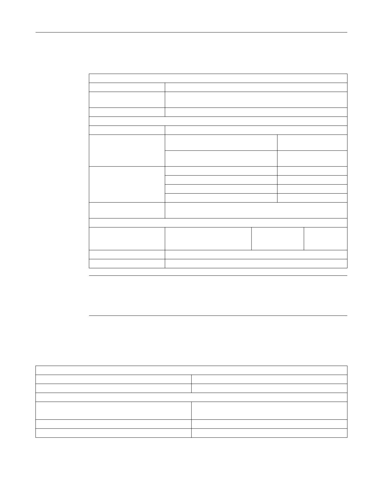
2.7.2
Connection module Basic PN
Safety
Safety class
III according to IEC 60536
Degree of protection accord-
IP54
ing to EN 60529
Approvals
CE / cULus
Electrical data
Input voltage
24 VDC (via X3 connector)
Current carrying capacity
Enabling button contacts (X20 connector)
max. each 0.5 A / 2-chan-
nel
Emergency stop button contacts (X21 con-
max. each 0.5 A / 2-chan-
nector)
nel
Max. power consumption
Connection module without external loading
0.3 A
Panel (HT 8)
1.6 A
5 status signals (X7 and X21)
2.5 A (0.5 A each)
Total:
4.4 A
Max. total
105.6 W
power consumption
Mechanical data
Dimensions
Height (without holder for termi-
Width:
Length:
nating connector):
165 mm
166 mm
66 mm
Weight
0.75 kg
Fall height, max.
1.20 m
Note
Information about the climatic and mechanical environmental conditions is contained in the
associated section under:
"General notes and interconnection" → "Operational planning".
2.7.3
PN terminal box
General data
Weight without packaging
Approx. 700 g
Degree of protection according to EN 60529
IP65 (with connected HT 8 or with inserted blanking cover)
Electrical data
Rated voltage
+24 V DC
Range, permissible
20.4 to 28.8 V (-15%, +20%)
Transients, maximum permissible
35 V (500 ms)
Time between two transients, minimum
50 s
Handheld units
Manual, 03/2016, 6FC5397-1AP40-5BA3
115
Handheld Terminal HT 8
2.9 Accessories
Current consumption of PN terminal box without HT 8
● Typical
● Approx. 100 mA
● Continuous current, maximum
● Approx. 150 mA
● Inrush current I2t
● Approx. 0.5 A2s
Current consumption of PN with HT 8, typical
Approx. 550 mA
Fuse, internal
Electronic
Current load PLC-accompanying signals
Max. 100 mA
Note
Recovery time
Wait for approximately one second after withdrawing the connecting cable from the connection
box before reinserting.
After power failures lasting less than one second the connecting cable has to be disconnected.
2.8
Spare parts
The following service set is available for SIMATIC connecting boxes PN Basic and PN Plus:
Designation
Remark
Quantity
Article number
Service set for mobile pan-
Dummy plugs for cable compartment
1
6AV6574-1AA04-4AA0
els
PG screw glands for connection box
2
Blanking cover for connecting a handheld ter-
1
minal
Terminal strips for connection box
3
2.9
Accessories
2.9.1
Overview
The following accessories are available for the HT 8:
Designation
Remark
Quantity
Article number
PN Plus terminal box
With automatic emergency stop override for
1
6AV6671-5AE11-0AX0 *)
mounting in the system
PN Basic terminal box
Without automatic emergency stop override for
1
6AV6671-5AE01-0AX0 *)
mounting in the system
PN Basic connection module
Without automatic emergency stop override for
6FC5303-0AA01-1AA0 *)
mounting in the control cabinet
Wall holder
For safekeeping, also suitable for stationary op-
1
6AV6574-1AF04-4AA0
eration
Touch pen
with holding loop
1
6FC5348-0AA08-4AA0
Handheld units
116
Manual, 03/2016, 6FC5397-1AP40-5BA3
Handheld Terminal HT 8
2.9 Accessories
Designation
Remark
Quantity
Article number
Protective membrane
for 8" touch display, type 10
2
6AV6671-5BC00-0AX0
Length: 2 m
1
6XV1440-4BH20 *)
Length: 5 m
1
6XV1440-4BH50 *)
Length: 8 m
1
6XV1440-4BH80 *)
Straight connecting cable
Length: 10 m
1
6XV1440-4BN10 *)
Length: 15 m
1
6XV1440-4BN15 *)
Length: 20 m
1
6XV1440-4BN20 *)
Length: 25 m
1
6XV1440-4BN25 *)
Spiral connection cable
1.5 m long, can be extended to 3.5 m
1
6FC5348-0AA08-3AA0
*) Safety related accessories
2.9.2
Wall holder
The HT 8 can be safely kept and operated in a stationary manner in the wall holder.
① Hook for the grip on the handheld unit
② Drill holes for screw fixing
Image 2-15 HT 8 wall holder - view
Ensure that you position the wall holder in such a manner that
● the display of the hung-in HT 8 is not exposed directly to the sun's rays.
● the HT 8 can be hung in based on ergonomic considerations. Therefore, choose a suitable
mounting height.
Handheld units
Manual, 03/2016, 6FC5397-1AP40-5BA3
117
Handheld Terminal HT 8
2.9 Accessories
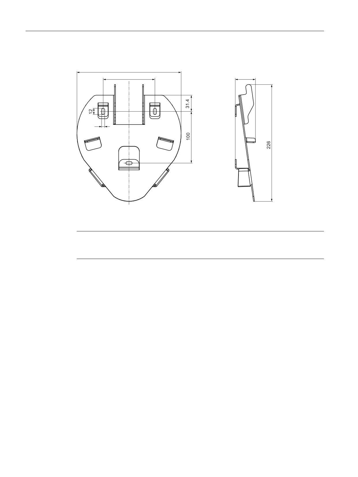
Dimension drawing
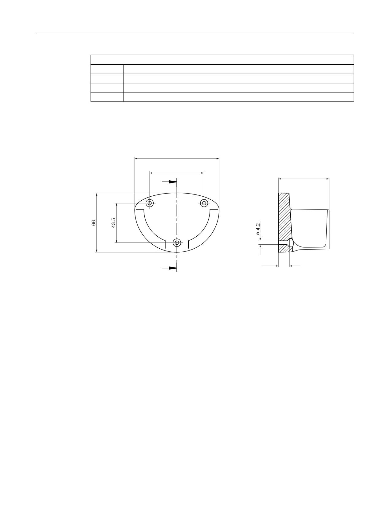
Image 2-16 HT 8 wall holder - dimension drawing
Note
Please note that the holder is smaller than the HT 8 (∅ approx. 290 mm). You must keep
sufficient clearance around the holder to ensure convenient handling.
Handheld units
118
Manual, 03/2016, 6FC5397-1AP40-5BA3
Mini-handheld unit
3
3.1
Description
The mini handheld unit (Mini HHU) is an easy-to-handle and ergonomic unit for setting up and
operating simple machines in the JobShop area or similar applications.
Since coarse, medium and fine infeed can easily be graduated, the operator control concept
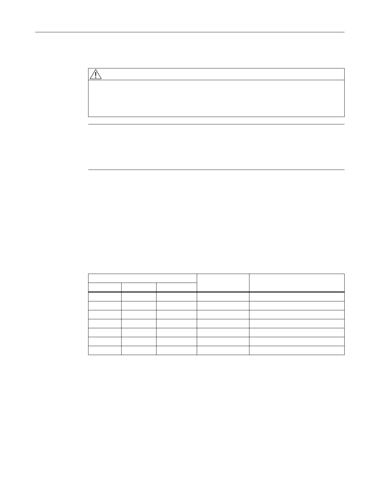
offers fast, increment-precise positioning. The signals are sent parallel to the CNC.
Features
● The mini HHU features a robust metal connector and is suitable for right-handed as well
as left-handed operators.
● Key labeling can be customized using slide-in labels.
● The mini handheld unit can be fixed on metal surfaces by means of the integrated magnetic
clamp. A holder shell is available as an option.
Validity
This description applies to:
Designation
Features
Article number
Mini HHU
With spiral connection cable, Emergency Stop button (2-
6FX2007-1AD03
channel), enabling button (3-stage), metal connector,
handwheel with magnetic latching
With straight cable, Emergency Stop button (2-channel),
6FX2007-1AD13
enabling button (3-stage), metal connector, handwheel
with magnetic latching
The safety-related accessories / spare parts are marked in the "Accessories and spare parts"
section with a *).
Handheld units
Manual, 03/2016, 6FC5397-1AP40-5BA3
119
Mini-handheld unit
3.2 Operator controls
3.2
Operator controls
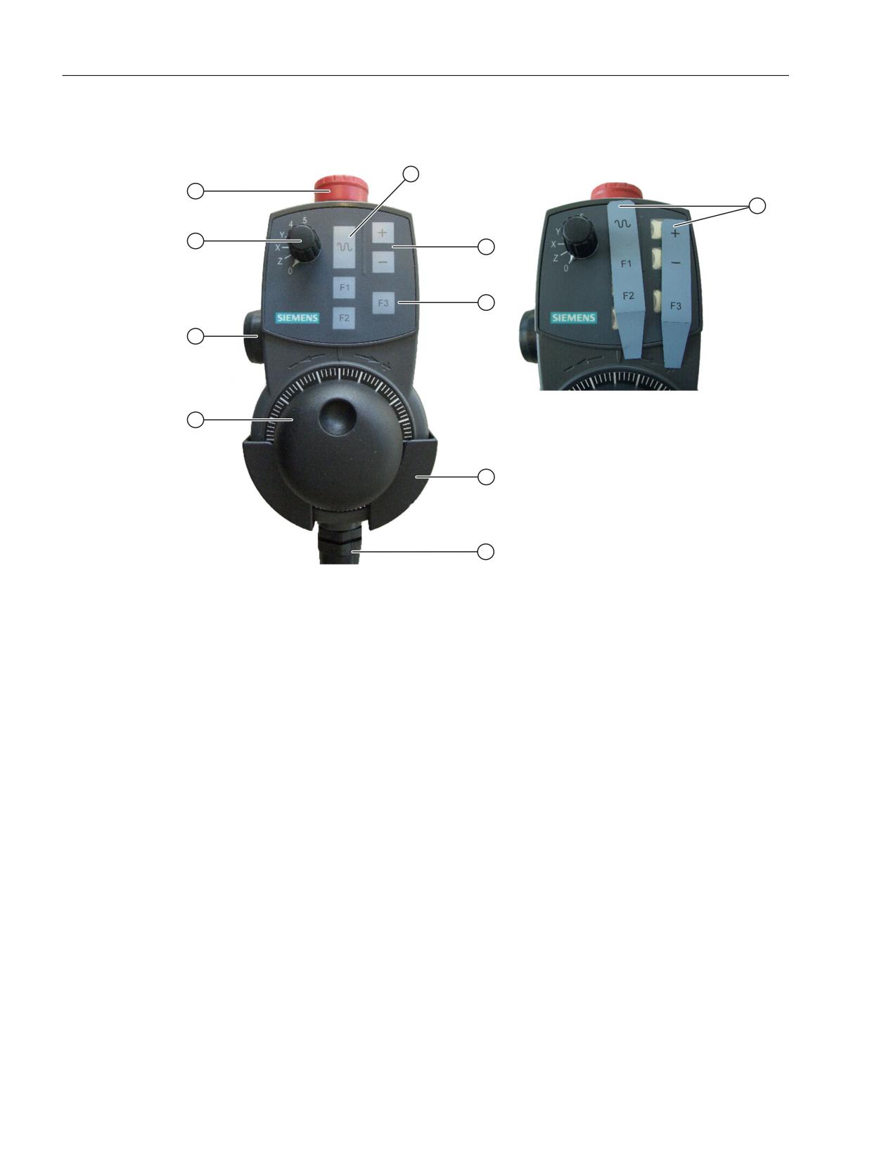
① Rapid traverse key for high-speed travel with traversing keys or handwheel
② Traversing keys +/- direction
③ F1, F2, F3 function keys for customer-specific applications (freely assignable)
④ Holder shell (optional)
⑤ Connecting cable
⑥ Handwheel
⑦ Enabling button, 2-channel, 3-stage
⑧ Axis selector switch for 5 axes and neutral position
⑨ Emergency Stop button, 2-channel
⑩ Slide-labels for ①, ② and ③
Image 3-1
View of mini handheld unit
Emergency Stop button
Press the red Emergency Stop button in emergencies when
● people are at risk,
● there is the danger of machines or the workpiece being damaged.
Handheld units
120
Manual, 03/2016, 6FC5397-1AP40-5BA3
Mini-handheld unit
3.2 Operator controls
Turn the Emergency Stop button clockwise to unlatch it.
WARNING
Danger of death due to premature restart
If you have shut down the system to be monitored, you can only release the emergency stop
button or put the system to be monitored back into operation if the condition that triggered
the emergency stop function has been corrected and a safe restart is carried out.
Note
Emergency Stop
As a rule, when operating the Emergency Stop button, all drives are brought to a standstill with
max. braking torque. For other responses to emergency stop, refer to the information supplied
by the machine tool manufacturer.
Enabling button
The enabling button is designed as a 3-way switch. This must be held in its central position
for traversing movements to be triggered.
Axis selector switch
You can select up to five axes with the axis selector switch. It is coded using Gray code.
Table 3-1
Coding of axis selection switch
Plug connector
Switch position
Function
Pin 8
Pin 9
Pin 10
0
0
0
-
Mini HHU not connected
1
1
0
0
No axis selected
0
1
0
Z
Z axis selected
0
1
1
X
X axis selected
1
1
1
Y
Y axis selected
1
0
1
4
Axis 4 selected
0
0
1
5
Axis 5 selected
Function keys
The function keys can be used to trigger machine-specific functions.
Traversing keys
The + and - traversing keys can be used to trigger traversing movements on the axis selected
via the axis selector switch.
Handheld units
Manual, 03/2016, 6FC5397-1AP40-5BA3
121
Mini-handheld unit
3.2 Operator controls
Handwheel
The handwheel can be used to initiate movements at the axis that has been selected with the
axis selector switch. The handwheel supplies two track signals with 100 increments/revolution.
Rapid traverse key
The rapid traverse key increases the traversing speed of the axis that has been selected with
the axis selector switch. The rapid traverse key affects traversing commands issued via the
+/- keys as well as handwheel signals.
Handheld units
122
Manual, 03/2016, 6FC5397-1AP40-5BA3
Mini-handheld unit
3.3 Dimension drawing
3.3
Dimension drawing
0DJQHWLF FODPS
SLQ FRQQHFWRU
:LWK XQLRQ QXW
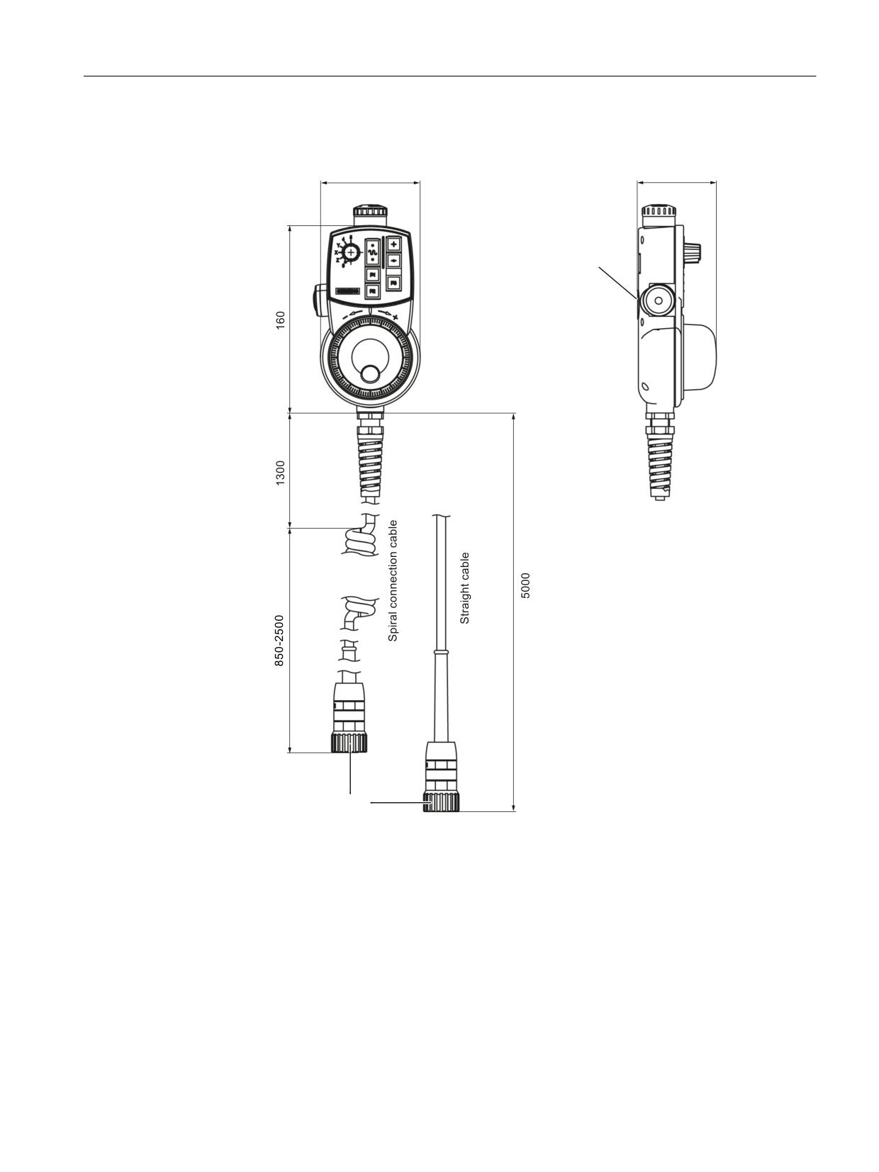
Image 3-2
Dimensions of the mini handheld unit
Handheld units
Manual, 03/2016, 6FC5397-1AP40-5BA3
123
Mini-handheld unit
3.4 Connecting
3.4
Connecting
Basic procedure
A connection kit is required to connect the mini HHU.
● You can use the preassembled connection kit to connect to an MCP. When doing this
please note that for the PROFIBUS version of the machine control panels, X55 is not
available. However, X70 is suitable for freely connecting the conductors if you do not require
a direct key connection.
● The non-assembled connection kit is available for free wiring. An angled socket is available
for this connection kit to change the cable outlet direction. This allows the flange socket of
the connection kit to be mounted 90° rotated.
This connection kit contains a metal flange socket for installation at the machine and a
terminating connector for overriding the emergency stop circuit when the mini HHU is not
connected.
0LQL ++8
IUHHO\ ZLUHG
SLQ 3KRHQL[ WHUPLQDO
1RW DVVLJQHG
EORFN ;
0&3 [[[ 31
;
SROH 'X%R[ SOXJ VRFNHW
3OXJ FRQQHFWRU
;
SROH 'X%R[ SOXJ VRFNHW
;
)ODQJH VRFNHW
SROH 'X%R[ SOXJ VRFNHW
;
SROH 68% ' VRFNHW FRQQHFWRU
$VVLJQPHQW RI WKH 'X%R[ SOXJ FRQQHFWRU
&RQQHFWLRQ NLW IRU PLQL ++8 DQ 0&3[[[ 31
;
;
;
&DEOH OHQJWK
P
9LHZ RI WKH SOXJ VLGH
Image 3-3
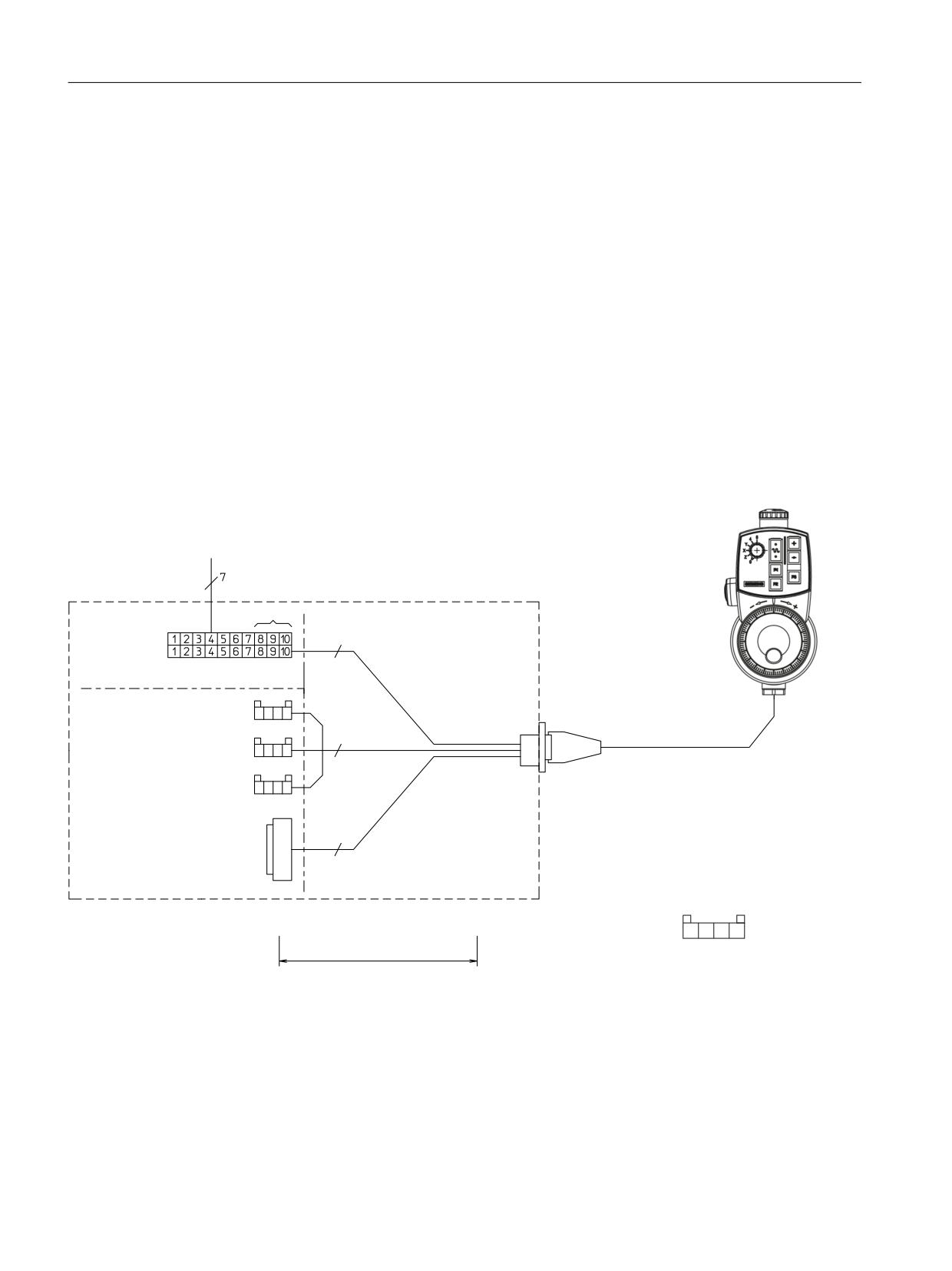
Connection diagram
1. Position the drilling pattern.
2. Route all the connecting cables through the large drill hole.
3. Mount the flange socket (with seal).
Handheld units
124
Manual, 03/2016, 6FC5397-1AP40-5BA3
Mini-handheld unit
3.4 Connecting
4. Plug the connecting cable into the mating connector according to the connector labeling.
5. Wire up the connections (at the machine) of the emergency stop and enabling button at
terminal block -X (see the circuit diagrams).
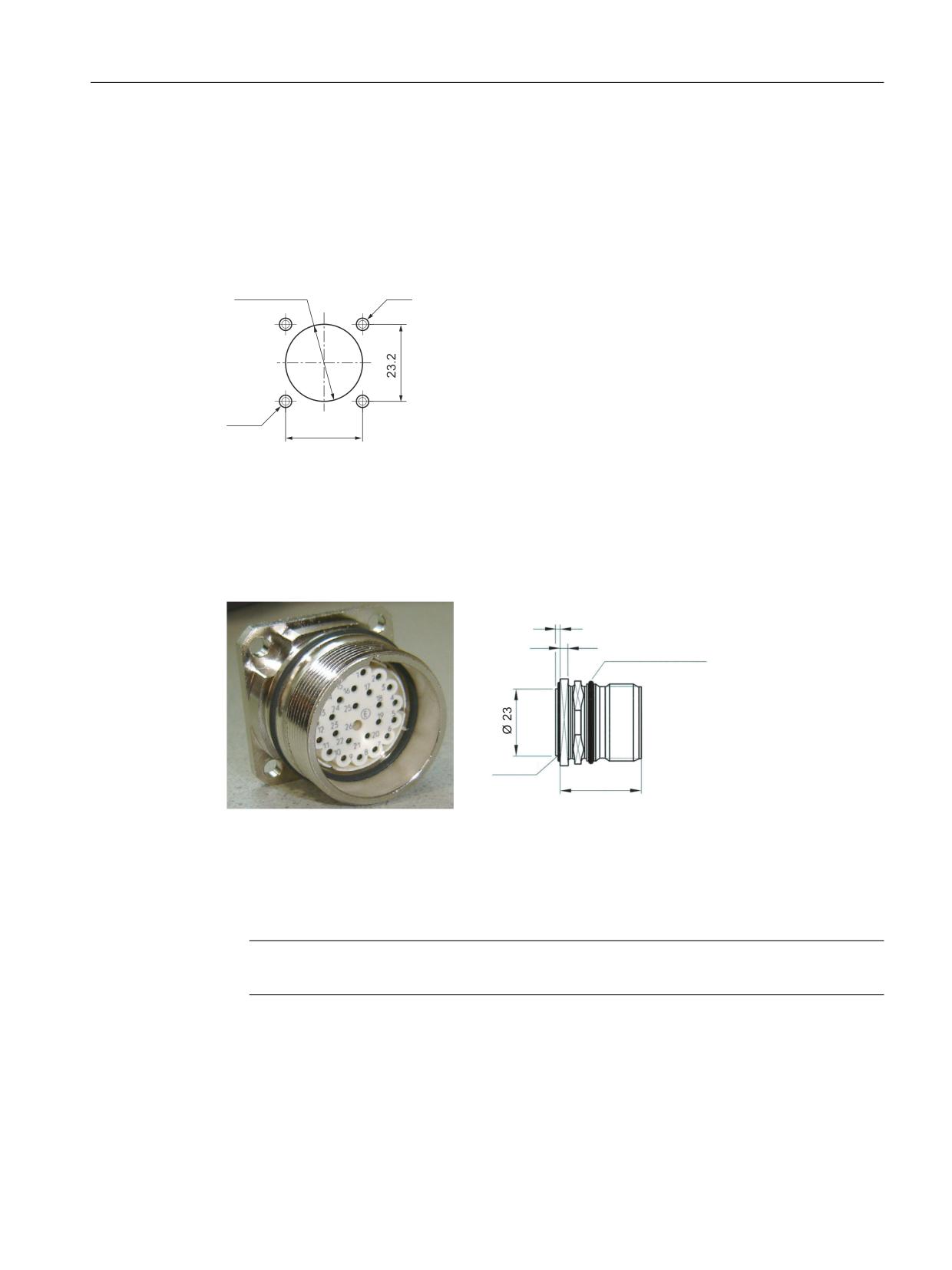
Drilling pattern for the flange socket mounting
º
s
0
º
Image 3-4
Drilling pattern for mounting
Flange socket
The mini HHU is connected using a flange socket. There is no need for an additional connection
distributor.
9LEUDWLRQ SURWHFWLRQ
2 ULQJ
Image 3-5
Flange socket
1. Plug the connector of the mini HHU (or the terminating connector) into the detent lugs/
guideways of the flange socket.
2. Tighten the screw cap to secure the connector.
Note
Failure to insert the connectors correctly can result in damage to the contacts.
Handheld units
Manual, 03/2016, 6FC5397-1AP40-5BA3
125
Mini-handheld unit
3.4 Connecting
If no mini HHU is connected, observe the following:
WARNING
Danger of death resulting from improper access
● After disconnection, the mini HHU must be locked away.
● Emergency stop buttons that are inactive must not be identified as such or must be
inaccessible. This is to prevent the emergency stop button from being used inadvertently.
Handheld units
126
Manual, 03/2016, 6FC5397-1AP40-5BA3
Mini-handheld unit
3.4 Connecting
Circuit diagrams
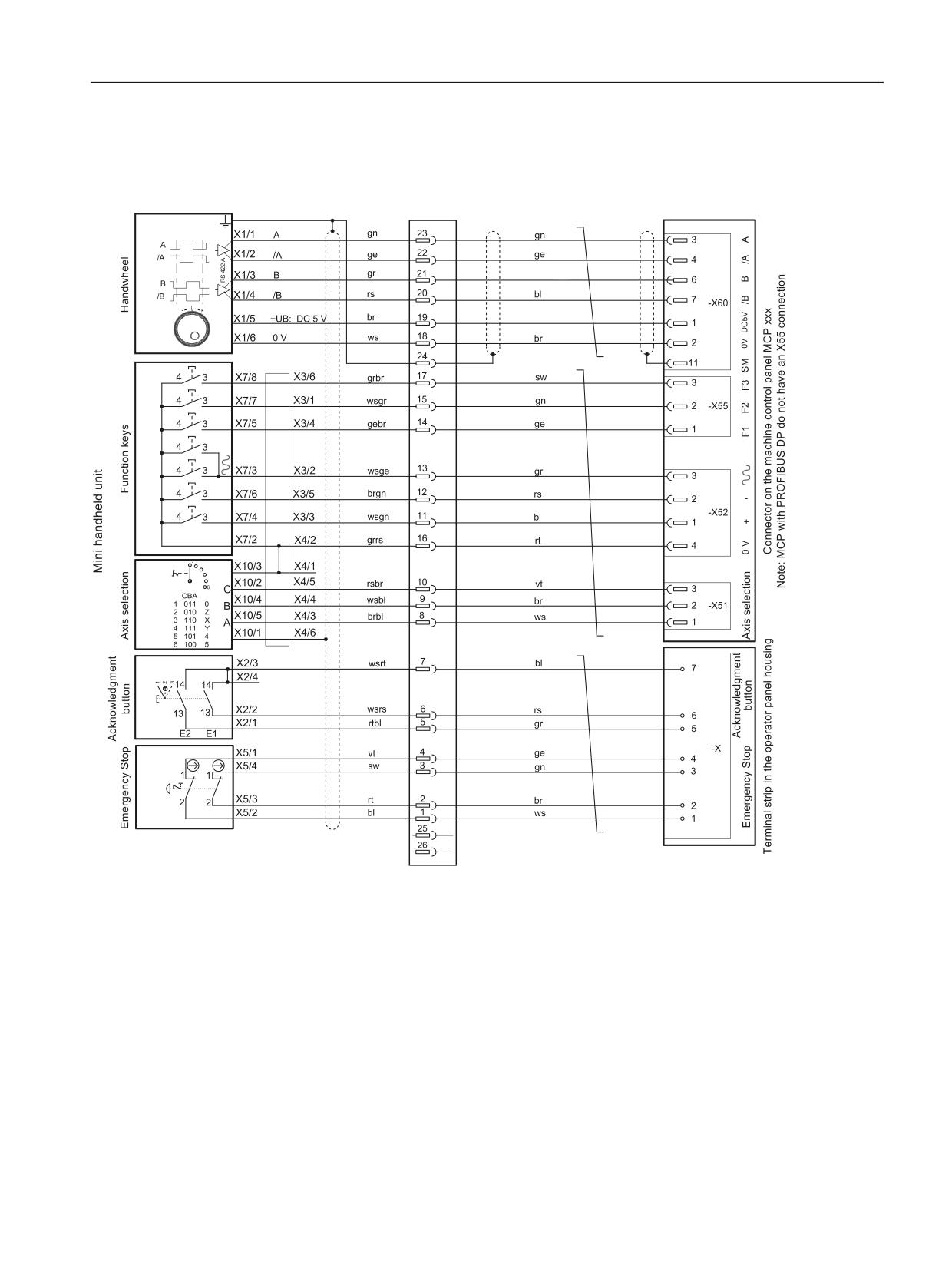
Circuit diagram for connection to the MCP
rt
sw
$
4x2x0.56mm²
6KLHOGHG
)
6
)
6
)
6
6
6
6
6
5x2x0.25mm²
6
6
5x2x0.25mm²
&RQGXFWRUV
PP
SLQ FRQQHFWRU
DW WKH RSHUDWRU SDQHO KRXVLQJ
bl
Blue
sw
Black
rsbr
Pink-brown
br
Brown
vt
Violet
rtbl
Red-blue
ge
Yellow
ws
White
wsbl White-blue
gn
Green
brbl
Brown-blue
wsge White-yellow
gr
Gray
gebr Yellow-brown
wsgr White-gray
rs
Pink
grbr
Gray-brown
wsrs Pink-white
rt
Red
grrs
Gray-pink
wsrt
White-red
Image 3-6
Connecting the mini HHU at MCP xxx using the preassembled connection kit
Handheld units
Manual, 03/2016, 6FC5397-1AP40-5BA3
127
Mini-handheld unit
3.5 Configuration
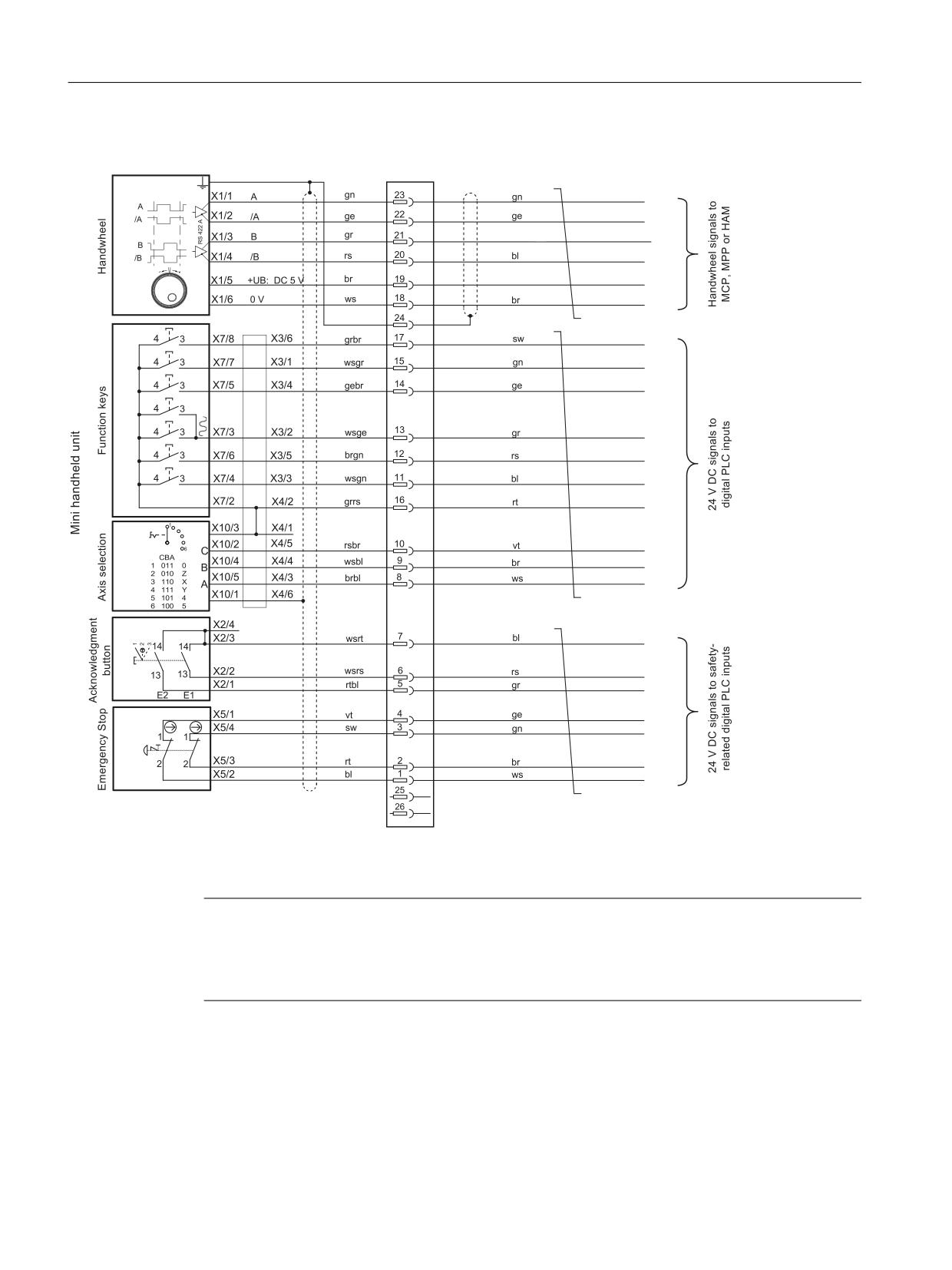
Circuit diagram for custom-specific wiring
rt
sw
$
4x2x0.56mm²
)
6
)
6
)
6
6
6
6
6
5x2x0.25mm²
6
6
5x2x0.25mm²
&RQGXFWRUV
PP
SLQ FRQQHFWRU
DW WKH RSHUDWRU SDQHO KRXVLQJ
Image 3-7
Principle connection of a mini HHU using the non-assembled connection kit
Note
Take care of the 0 V and the supply voltage wiring when connecting the axis selection switch
and the function keys. Also observe the max. switching power of the contact blocks.
The handwheel can also be routed to the MCP PN interface.
3.5
Configuration
Configuring the mini HHU involves setting FB1 parameters in OB100 of the basic PLC program:
See Function Manual Basic Functions, Basic PLC Program (P3 sl)
Handheld units
128
Manual, 03/2016, 6FC5397-1AP40-5BA3
Mini-handheld unit
3.5 Configuration
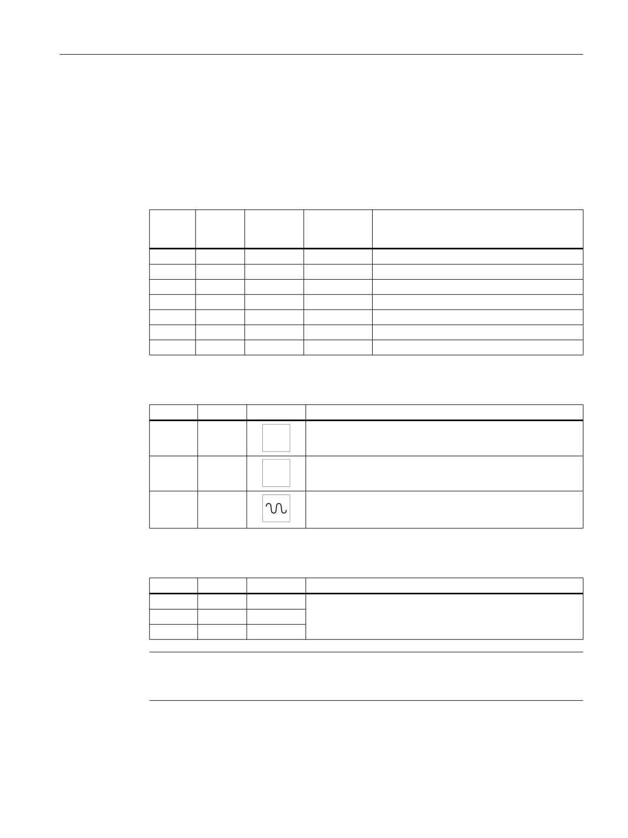
Example: Connecting a mini HHU to an MCP xxx PN
The mini HHU is connected to connectors X51, X52, X55 and X60 of an MCP xxx PN.
The customer keys (X51 - X55) of the MCPs then cannot be used for other applications.
Information concerning the coding of the machine functions on the mini HHU and details of
the connection to the customer keys are provided in the tables below.
Table 3-2
Coding of axis selection switch X51:
21
22
23
Switch
Function
X51.1
X51.2
X51.3
position
KT-IN1
KT-IN2
KT-IN3
0
0
0
-
Mini HHU not connected
1
1
0
0
No axis selected
0
1
0
Z
Z axis selected
0
1
1
X
X axis selected
1
1
1
Y
Y axis selected
1
0
1
4
Axis 4 selected
0
0
1
5
Axis 5 selected
Table 3-3
X52 traversing keys / rapid traverse key coding:
Pin
Button
Function
KT-IN4
X52.1
Travel key + direction
KT-IN5
X52.2
Travel key - direction
KT-IN6
X52.3
Rapid traverse key
Table 3-4
X55 function keys coding:
Pin
Button
Function
KT-IN7
X55.1
F1
KT-IN8
X55.2
F2
Function keys
KT-IN9
X55.3
F3
Note
For the assignment of the customer keys to the input images, refer to the appropriate section
of the particular machine control panel.
Handheld units
Manual, 03/2016, 6FC5397-1AP40-5BA3
129

Mini-handheld unit
3.7 Technical specifications
3.6
Maintenance and Service
Cleaning the device
Use a soft cloth moistened either with water or a mild cleaning agent to clean the housing and
operator control elements of the mini HHU.
Checking the device
In order to prevent foreign bodies or liquids entering the mini HHU, regularly check the device
● that all the housing screws are in place and tight
● for damage to the housing
● for damage to the cable cover or cable entry
Protect the device from environmental effects
Protect the mini HHU against
● direct solar radiation and heat sources
● mechanical vibration and shock
● dust
● moisture, and
● strong magnetic fields
Checking the emergency stop button and the enabling button
Check the emergency stop button regularly to ensure that it functions correctly.
Check the enabling button regularly to ensure that it functions correctly in the enable and panic
position.
WARNING
Danger of death resulting from damaged mini-handheld device
Immediately check the functioning of the emergency stop button and the enabling button if
the device was subject to significant shock (e.g. because it was dropped).
3.7
Technical specifications
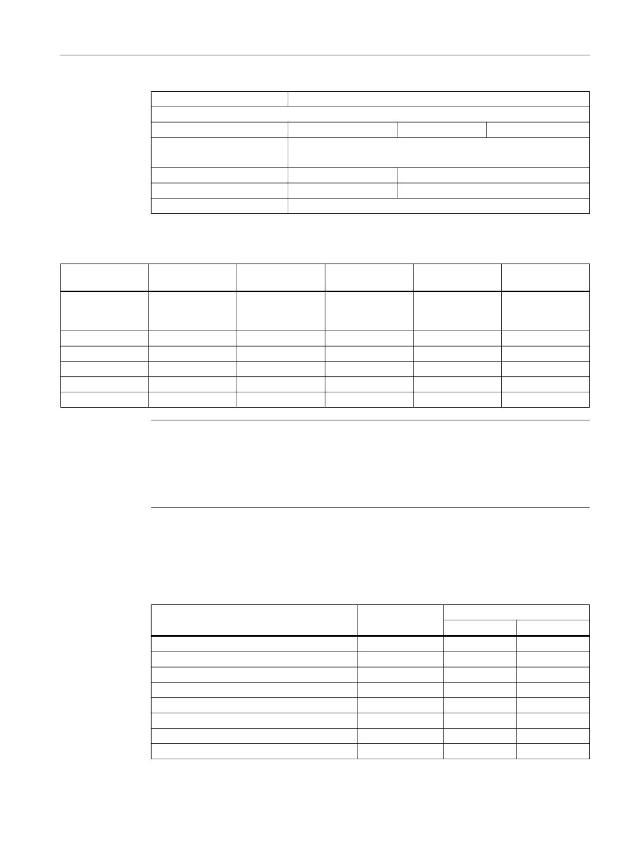
Table 3-5
Mini handheld unit
General data
Approvals
CE / cULus
Handheld units
130
Manual, 03/2016, 6FC5397-1AP40-5BA3
Mini-handheld unit
3.8 Spare parts / accessories
Degree of protection
IP65 - according to DIN EN 60529
Mechanical data
Dimensions approx.
Height: 180 mm
Width: 90 mm
Depth: 67 mm
Weight
Approx. 0.5 kg without connecting cable
Approx. 1.3 kg with connecting cable
Environmental conditions
Operation
Storage/transport
Temperature ranges
0 ... 55° C
-20 ... 60° C
Relative humidity
Max. 80% (condensation not permissible)
Table 3-6
Control elements
Emergency Stop
Enabling buttons
Handwheel
Function keys
Axis selector
button
switch
General
2 channel, accord-
2-channel, 3-stage
according to RS
-
-
ing to
422
EN ISO 13850
Contact block
2 x NC contact
2 x NO contacts
100 S/R
NO contact
Gray code
Switching voltage
24 VDC
24 VDC
5 VDC ± 5%
Max. 30 VDC
Max. 25 VDC
Switching current
2 A
90 mA
Max. 0.1 A
-
Contact rating
-
-
Max. 1 VA
Max. 0.2 VA
Reliability
B10d = 100 000
B10d = 100 000
-
-
-
Note
The quantitative assessment of the emergency stop and enabling safety functions must be
based on the B10d value corresponding to the used standards (e.g. ISO 13849-1) under
consideration of the respective application (frequency of the actuation, service life, diagnostics
by the evaluation unit, etc.). The B10d values only apply when the technical properties of the
emergency stop and enabling buttons are taken into account.
3.8
Spare parts / accessories
The following accessories and spare parts can be supplied:
Item name
Article number
Can be used with 6FX2007-
-1AD03
-1AD13
6-pos. selector switch with accessories
104899
X
X
Emergency Stop button
104900 *)
X
X
ZXE-104833 (3-stage enabling button)
104901 *)
X
X
Protective cap and nut for ZXE
104902 *)
X
X
3.5 m spiral connecting cable
104903 *)
X
5 m straight connecting cable
104904 *)
X
5 m (straight) extension cable
103832 *)
X
X
10 m (straight) extension cable
103833 *)
X
X
Handheld units
Manual, 03/2016, 6FC5397-1AP40-5BA3
131
Mini-handheld unit
3.8 Spare parts / accessories
Item name
Article number
Can be used with 6FX2007-
-1AD03
-1AD13
15 m (straight) extension cable
103834 *)
X
X
Connecting adapter (0.5 m adapter cable; met-
103835 *)
X
X
al coupling on mini HHU side to T+B plastic
coupling on panel side)
Connector disassembly tool
105037
X
X
*) Safety-related
Ordering address
Euchner GmbH + Co. KG
Vertrieb Technik
Kohlhammerstr. 16
70771 Leinfelden-Echterdingen
Germany
Phone +49 (0) 711 7597-0
Fax +49 (0) 711 7597-303
Table 3-7
Further accessories
Component
Article number
Remark
Connection kit
6FX2006-1BG11 *)
Assembled, metal version, with terminating connector
Connection kit
6FX2006-1BG03 *)
Non-assembled, metal version, with terminating con-
nector
Angled socket
6FX2006-1BG56 *)
Metal version, for non-fabricated connection kit
Adapter plate
6FX2006-1BG45
Plastic to metal version
Retaining shell
6FX2006-1BG70
including 3 M4 screws
*) Safety-related
Handheld units
132
Manual, 03/2016, 6FC5397-1AP40-5BA3
Mini-handheld unit
3.8 Spare parts / accessories
Retaining shell
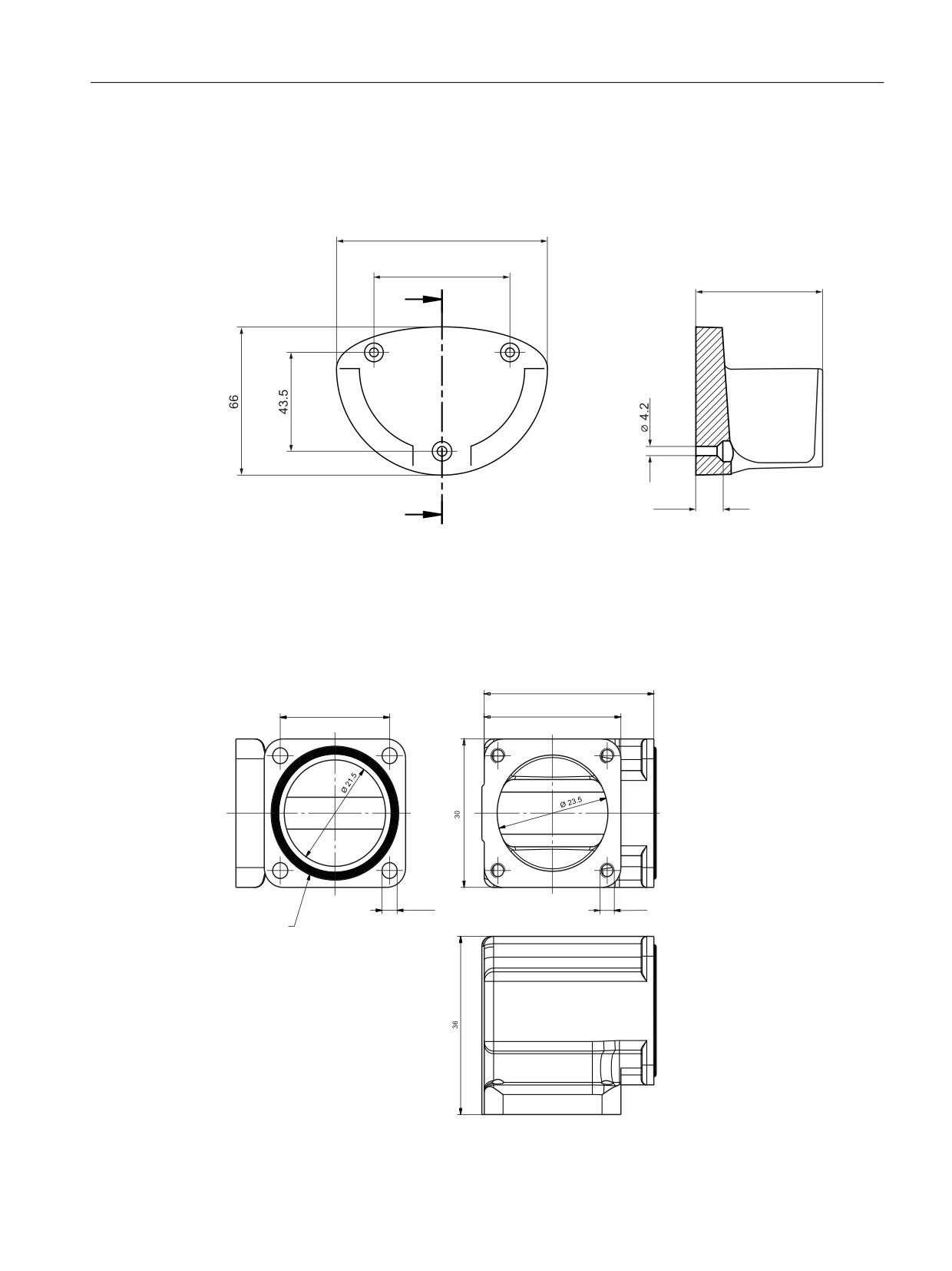
Optionally, the mini handheld unit can be stored in a screw-on retaining shell. The retaining
shell is mounted using three M4 screws (included in scope of delivery).
Image 3-8
Dimension drawing for mounting the retaining shell
Angled socket
An angled socket is available as an option, which permits the cable outlet direction to be rotated
through 90°.
s
ഋ
s
s
[
0
[
2 ULQJ
Image 3-9
Dimension drawing of angled socket
Handheld units
Manual, 03/2016, 6FC5397-1AP40-5BA3
133
Mini-handheld unit
3.8 Spare parts / accessories
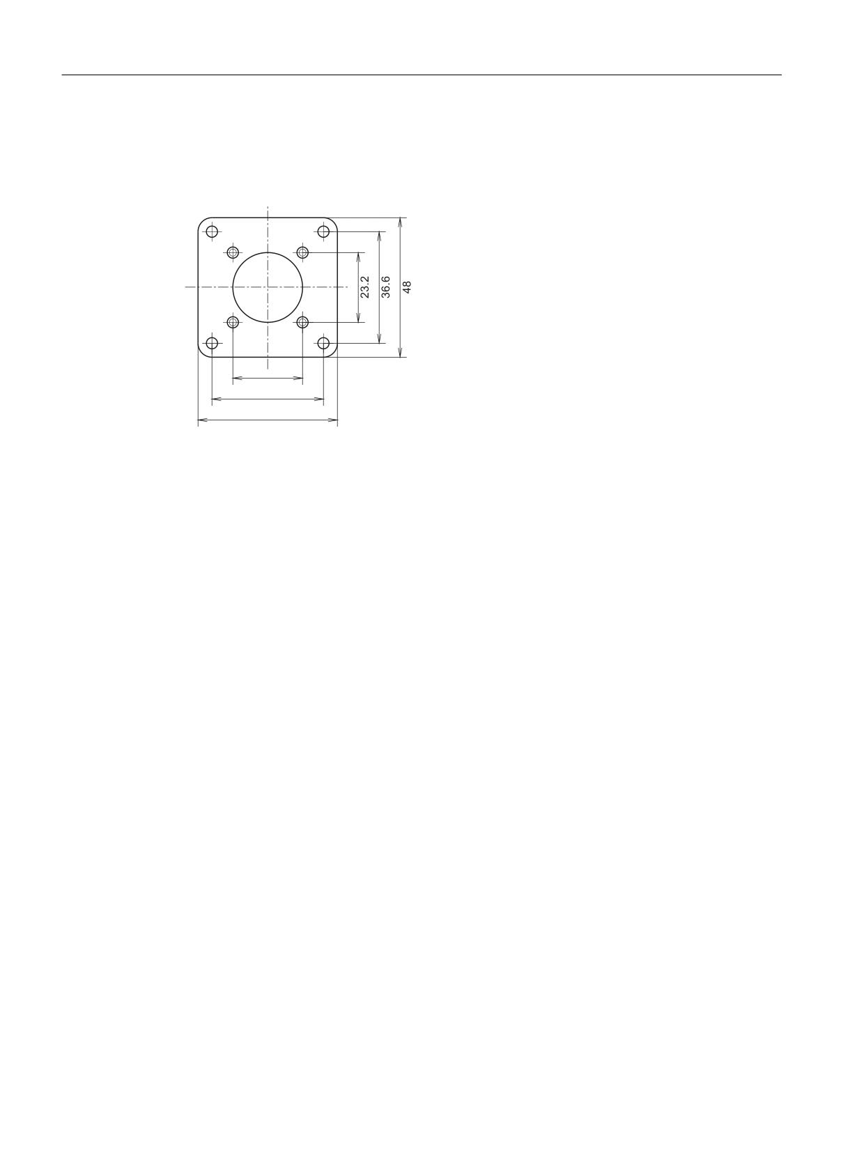
Adapter plate
The adapter plate is only required if the metal flange socket is being mounted at an installation
location intended for plastic flange sockets.
Image 3-10 Dimension drawing of the adapter plate
Slide-in labels
The slide-in labels can be replaced. To do this, you must unscrew the six TORX screws on
the rear of the housing. The housing can now be taken apart. The slide-in labels can now be
pulled out of the guide on the front plant and replaced, if required.
Make sure that no connection cables are pinched during the re-assembly.
Handheld units
134
Manual, 03/2016, 6FC5397-1AP40-5BA3
Electronic handheld handwheel
4
4.1
Description
The handheld handwheel is intended for use in conjunction with machines. A magnetic bracket
and spiral connection cable can be found on its enclosure. The magnetic bracket (retaining
magnet) enables the handwheel to be attached to metallic surfaces. So that it can also be
safely stored on non-magnetic surfaces, there is also a retaining shell available (see Section:
"Accessories").
The electronic handheld handwheel is an incremental encoder that generates signals
according to how the manually operated wheel is rotated.
The handwheel's magnetic latching facility makes for an extremely precise incremental
process. The axis selected via the control can be positioned so that the axes are parallel.
The handheld handwheel offers a PPR count of 100 S/R.
Validity
The description applies to the following electronic handheld handwheel:
Designation
Interface
Article number
Electronic handheld handwheel
5 VDC, RS 422
6FC9320-5DE02
Handheld units
Manual, 03/2016, 6FC5397-1AP40-5BA3
135
Electronic handheld handwheel
4.1 Description
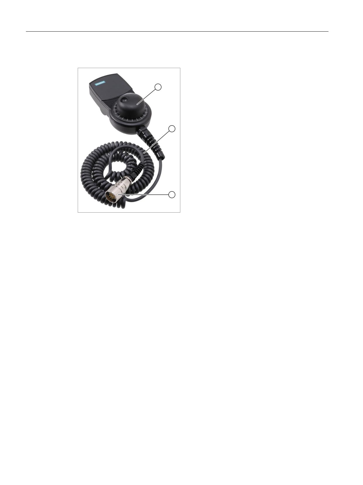
Display
① Handwheel
② Spiral connection cable
③
9-pin connector
Image 4-1
View of electronic handheld handwheel
Handheld units
136
Manual, 03/2016, 6FC5397-1AP40-5BA3
Electronic handheld handwheel
4.2 Dimension drawing
4.2
Dimension drawing
Front view and side view
5HWDLQLQJ PDJQHW
SLQ FRQQHFWRU
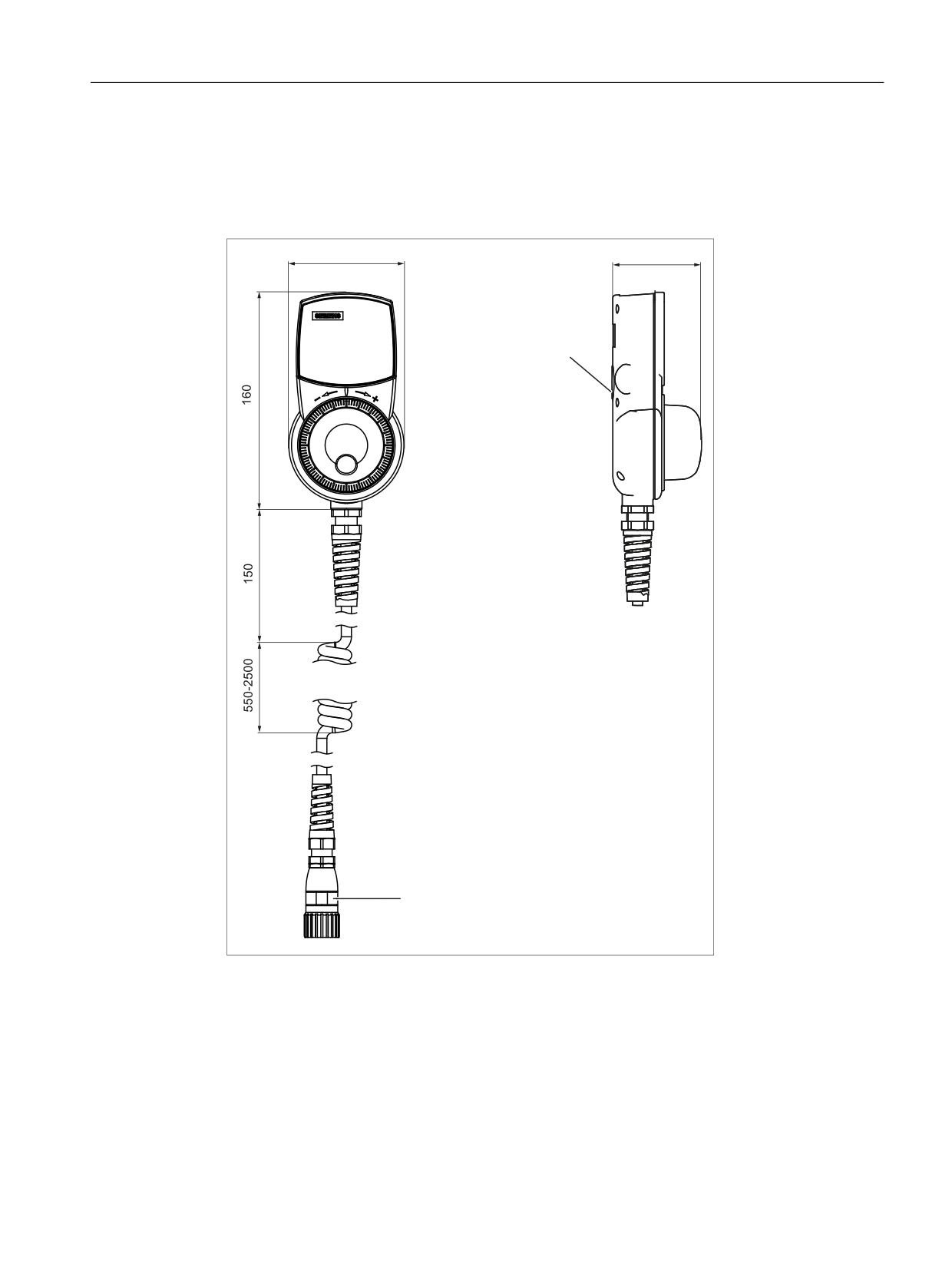
Image 4-2
Dimensions of the electronic handheld handwheel
Handheld units
Manual, 03/2016, 6FC5397-1AP40-5BA3
137
Electronic handheld handwheel
4.3 Connection
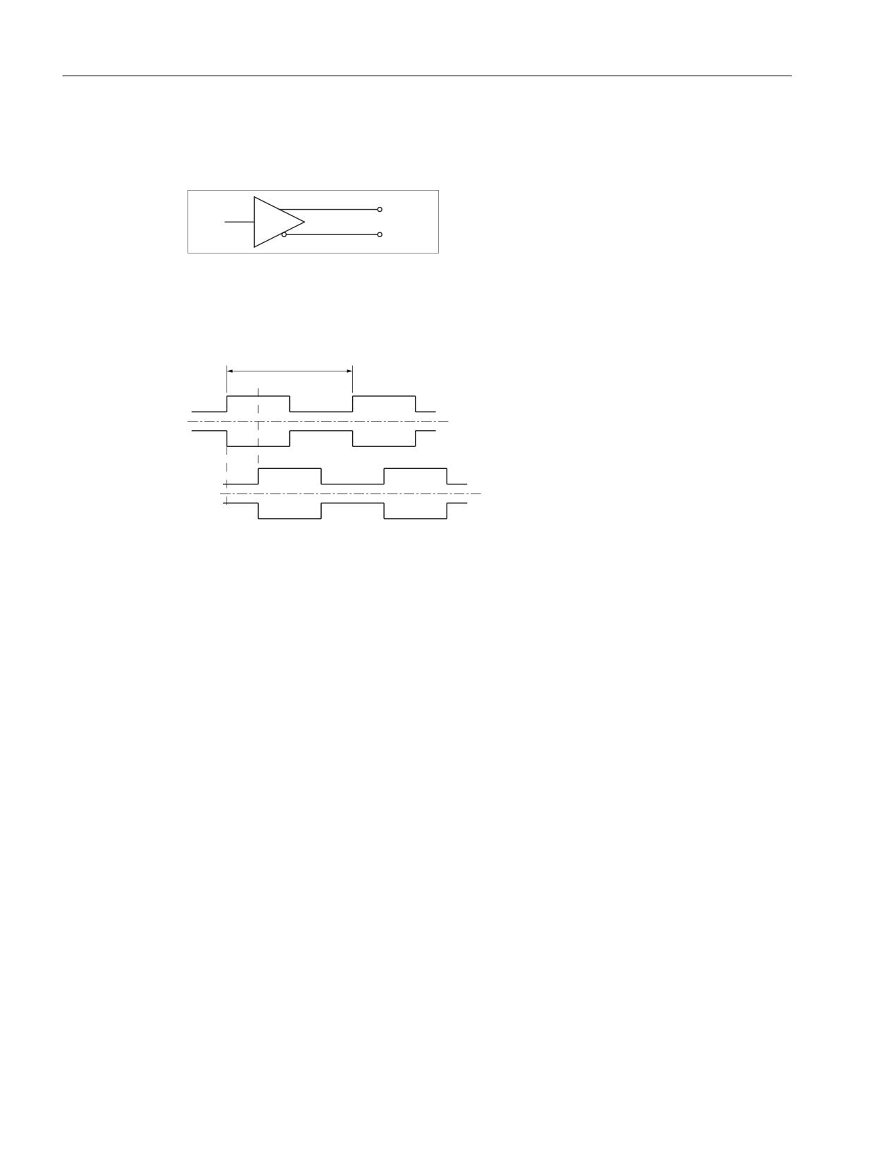
Outputs
RS 422 A
$%
&
$ %
Load current ≦ 20 mA
Pulse diagram
VWHS
$
$
%
%
4.3
Connection
The handheld handwheel is connected via a flange socket using the spiral connection cable.
The article numbers for the recommended flange can be found in Section "Accessories".
Handheld units
138
Manual, 03/2016, 6FC5397-1AP40-5BA3
Electronic handheld handwheel
4.4 Technical specifications
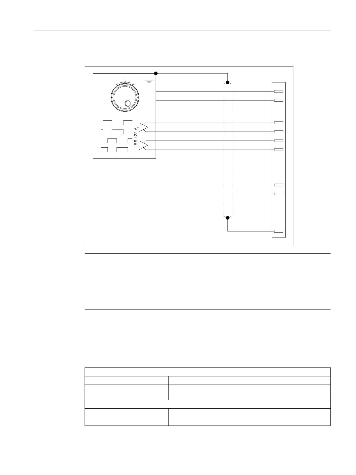
Electrical connection diagram
;
9
ZK
;
8%
9'& s
EQ
;
$
JQ
$
;
$
\H
$
;
%
J\
%
;
%
SN
%
8QDVVLJQHG
6KLHOG
Note
When a connected handwheel triggers pulses from its idle position or in the event of a slight
touch, connect it so that the label is facing the wrong way.
Swap:
● The wires of terminal A with those of terminal /A
● The wires of terminal B with those of terminal /B
4.4
Technical specifications
Table 4-1
Electronic handheld handwheel
Safety
Safety class
I
Degree of protection according to
IP65
EN 60529
Electrical data
Operating voltage
5 VDC ± 5%
Current consumption
Max. 80 mA
Handheld units
Manual, 03/2016, 6FC5397-1AP40-5BA3
139
Electronic handheld handwheel
4.5 Accessories
Limit frequency
10 kHz
Number of pulses
100 increments/revolution
Displacement of phase A to B
Typ. 90° electrical
Interface
RS 422
Mechanical data
Dimensions approx.
Height: 160 mm
Width: 85 mm
Depth: 67 mm
Weight
0.3 kg (without spiral connection cable)
Housing material
Thermoplastic
Distance to NCU
20 m
Actuating force
4 Ncm
Speed
Max. 1,000 rpm
Note
Information about the climatic and mechanical environmental conditions is contained in the
associated section under:
"General notes and interconnection" → "Operational planning".
4.5
Accessories
The following components are available as accessories for the electronic handheld handwheel:
Component
Description
Article number
Flange socket
9-pin flange socket
6FC9341-1AQ
Holder
Providing a place to store the
6FX2006-1BG70
handwheel in the case of non-
metallic surfaces
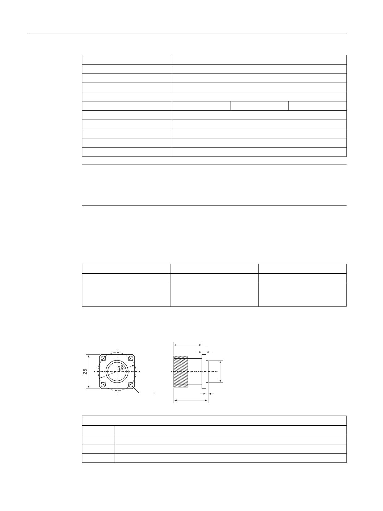
Dimension drawing of the flange socket
Pin assignment
Pin
Signal
1
5 V
2
0 V
3
B
Handheld units
140
Manual, 03/2016, 6FC5397-1AP40-5BA3
Electronic handheld handwheel
4.5 Accessories
Pin assignment
4
A
5
*A
6
*B
9
Shield
Dimension drawing of the holder
Optionally, the handheld electronic handwheel can be stored in a screw-on holder. The holder
is mounted using three M4 screws (included in the scope of delivery).
Image 4-3
Dimension drawing for mounting the holder
Handheld units
Manual, 03/2016, 6FC5397-1AP40-5BA3
141
Electronic handheld handwheel
4.5 Accessories
Handheld units
142
Manual, 03/2016, 6FC5397-1AP40-5BA3
Handwheel connection module
5
5.1
Description
The SINUMERIK handwheel connection module for PROFIBUS can be used to connect two
handwheels or the handwheel of the handheld unit B-MPI and the mini handheld unit.
On the handwheel connection module for PROFIBUS, digital inputs, outputs, connections for
rotary override switches and handwheels are provided as well as a PROFIBUS DP interface
for communication.
The handwheel connection module for PROFIBUS is mounted into the control cabinet.
Validity
The following description applies to the handwheel connection module for PROFIBUS.
Article number: 6FC5303-0AA02-0AA0
Features
PROFIBUS DP interface for:
●
6 inputs
●
6 inputs and 6 outputs (additional cable set required)
●
16 direct keys of OP 012/OP 015A/TP 015A
●
2 handwheels
Handheld units
Manual, 03/2016, 6FC5397-1AP40-5BA3
143
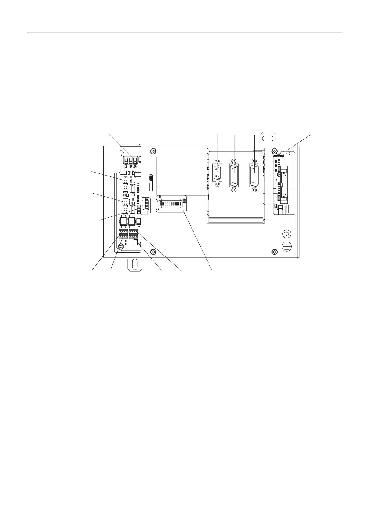
Handwheel connection module
5.2 Interfaces
5.2
Interfaces
5.2.1
Overview
Location of the interfaces
;
;
;
;
6
;
;
;
/('V
+
+
;
;
;
;
6
Image 5-1
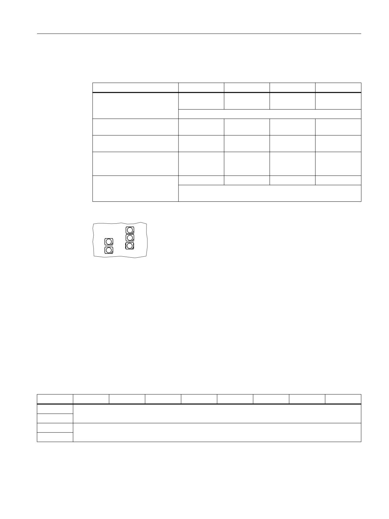
Handwheel connection module - location of the interfaces
X10
Power supply interface
X20
PROFIBUS DP interface
X30
Feedrate override
X31
Spindle override
X51 / X52
Customer-specific operator controls (pushbuttons incl. 24 V lamps)
X53 / X54
24 V control for customer pushbutton lamps
X60 / X61
Connections for two handwheels (TTL/differential)
X70
Direct keys interface for connecting the operator panel front direct keys
Jumper S1
Setting the handwheel signal type
- S1 open: TTL
- S1 closed: Differential interface
S3 DIP switch
Setting of the PROFIBUS address
(see Settings via DIP switch S3 (Page 147))
Handheld units
144
Manual, 03/2016, 6FC5397-1AP40-5BA3
Handwheel connection module
5.2 Interfaces
LED displays
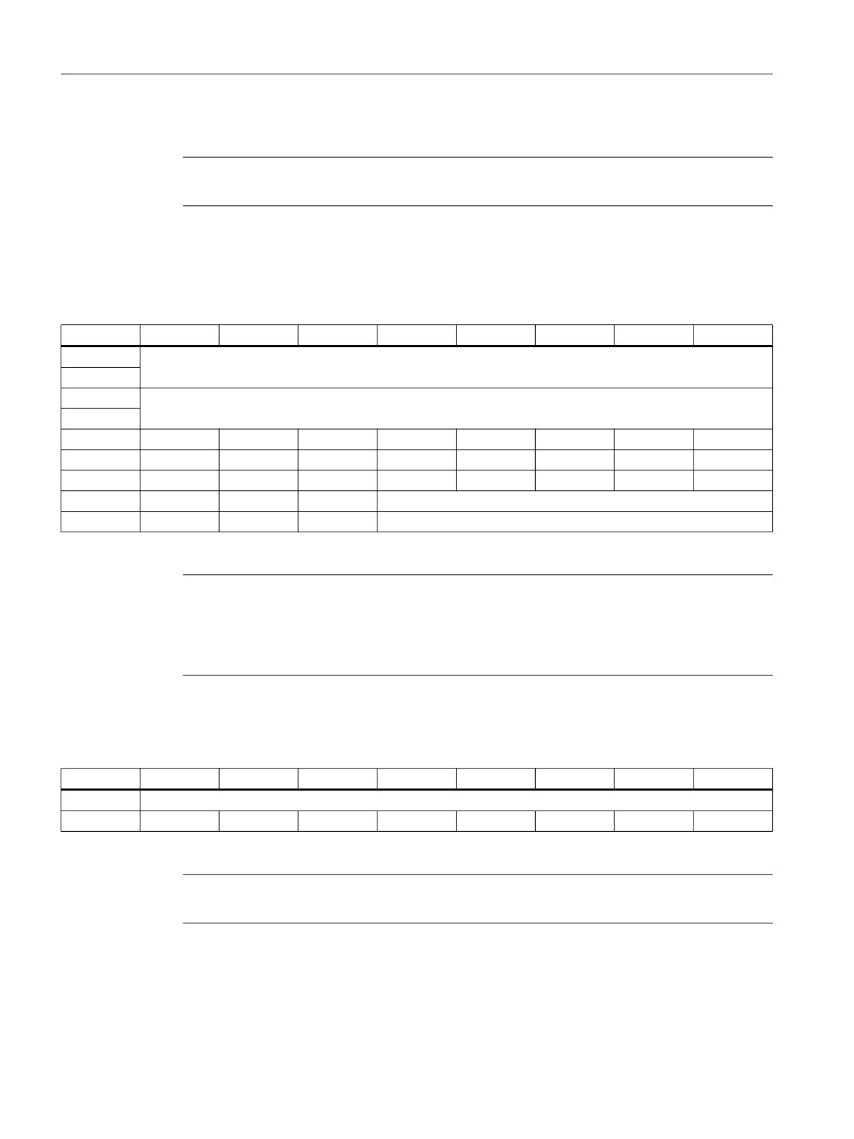
LEDs H1 to H5 provide information about the following states:
Diagnostics
H1
H3
H4
H5
Power On
Lights up red
Lights up green
Lights up or-
Lights up red/off
ange
The LEDs light up for approx. 4 s.
GD communication
Off
Lights up green
Flashes orange
Lights up red
(80 Hz)
There is no PROFIBUS com-
Lights up red
Lights up green
Off
Flashes green
munication.
(bus error)
(approx. 25 Hz)
HAM is configured as PROFI-
Off
Lights up green
Off/orange
Lights up green
BUS slave and with cyclic data
exchange.
Fatal error LED display
flashes red
flashes green
flashes orange
flashes green
For fatal software errors and incorrect DIP switch settings, the LEDs
flash very quickly.
LED H2 is reserved for service and is always off.
+
+
+
+
+
Image 5-2
Layout of the LEDs
Pin assignment
For more detailed information, see "General information and networking", Chapter:
"Connecting".
5.2.2
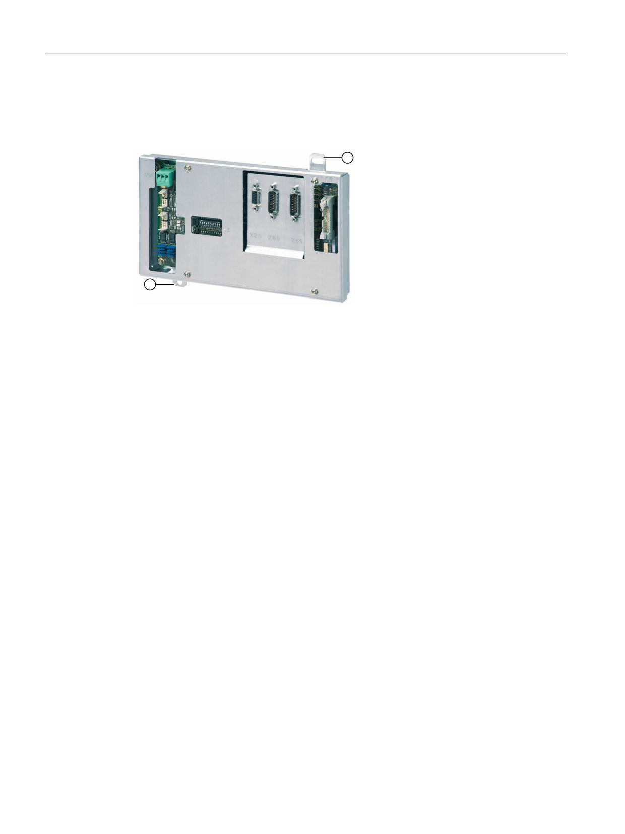
Input / output images
Handwheel
Table 5-1
Input image
Byte
Bit7
Bit6
Bit5
Bit4
Bit3
Bit2
Bit1
Bit0
EB n + 0
Handwheel 1
counter status (16 bit signed)
EB n + 1
EB n + 2
Handwheel 2
counter status (16 bit signed)
EB n + 3
Handheld units
Manual, 03/2016, 6FC5397-1AP40-5BA3
145
Handwheel connection module
5.2 Interfaces
Note
No output process image exists.
Handwheel + additional I/Os
Table 5-2
Input image
Byte
Bit7
Bit6
Bit5
Bit4
Bit3
Bit2
Bit1
Bit0
EB n + 0
Handwheel 1
counter status (16 bit signed)
EB n + 1
EB n + 2
Handwheel 2
counter status (16 bit signed)
EB n + 3
EB n + 4
DT_07
DT_06
DT_05
DT_04
DT_03
DT_02
DT_01
DT_00
EB n + 5
DT_15
DT_14
DT_13
DT_12
DT_11
DT_10
DT_09
DT_08
EB n + 6
-
-
KT_6
KT_5
KT_4
KT_3
KT_2
KT_1
EB n + 7
-
-
-
Rotary switch 1 (5 bit) connector X30
EB n + 8
-
-
-
Rotary switch 2 (5 bit) connector X31
Note
DT_xx corresponds to direct key xx of connector X70.
KT_x corresponds to customer key x.
(connection of free customer keys or a direct key module.)
Table 5-3
Output image
Byte
Bit7
Bit6
Bit5
Bit4
Bit3
Bit2
Bit1
Bit0
AB n + 0
Reserved, must be assigned value 0.
AB n + 1
-
-
KL_6
KL_5
KL_4
KL_3
KL_2
KL_1
Note
KL_x corresponds to customer lamp x.
Handheld units
146
Manual, 03/2016, 6FC5397-1AP40-5BA3
Handwheel connection module
5.3 Settings via DIP switch S3
5.3
Settings via DIP switch S3
Delivery condition
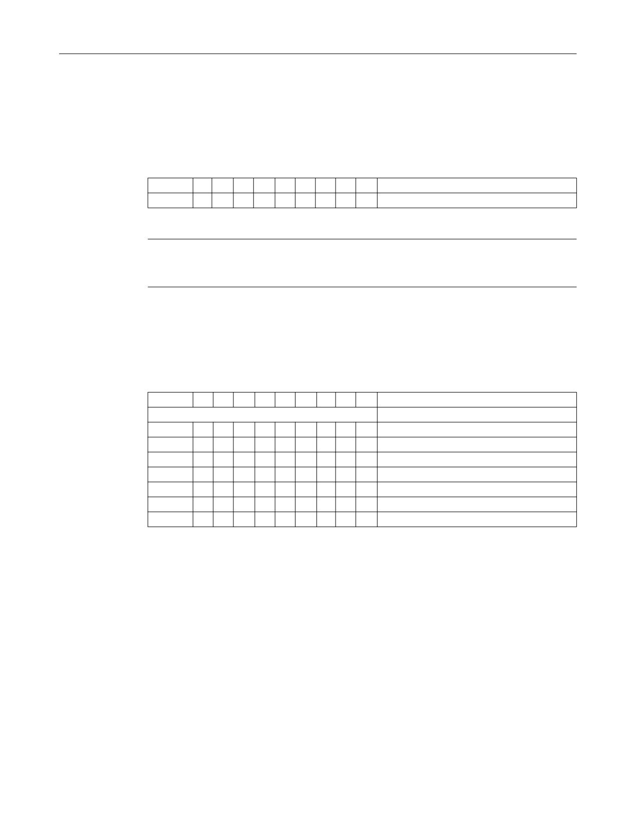
Table 5-4
Delivery condition setting
1
2
3
4
5
6
7
8
9
10
Meaning / value
on
off
on
off
on
on
off
off
off
off
Series
Note
The delivery condition setting MUST be changed in accordance with the "Assignment of the
DIP switch S3" table (below).
Connection type: PROFIBUS DP
For PROFIBUS DP, the PROFIBUS address is set using switches 1 to 10:
Table 5-5
Assignment of DIP switch S3
1
2
3
4
5
6
7
8
9
10
Meaning/value
PROFIBUS
off
off
off
off
off
off
off
-
on
on
0
on
off
off
off
off
off
off
-
on
on
1
off
on
off
off
off
off
off
-
on
on
2
on
on
off
off
off
off
off
-
on
on
3
:
:
:
:
:
:
:
-
-
-
: (etc.)
on
off
on
on
on
on
on
-
on
on
125
off
on
on
on
on
on
on
-
on
on
126
Handheld units
Manual, 03/2016, 6FC5397-1AP40-5BA3
147
Handwheel connection module
5.4 Mounting
5.4
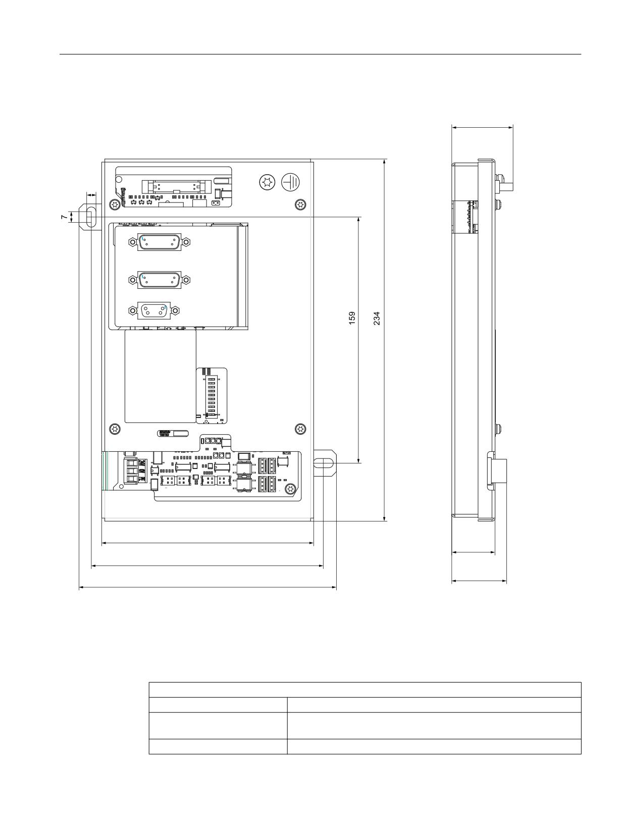
Mounting
The handwheel connection module is intended for mounting onto the control cabinet wall
Use both lugs ① to secure it in place.
Image 5-3
Front view of handwheel connection module
Handheld units
148
Manual, 03/2016, 6FC5397-1AP40-5BA3
Handwheel connection module
5.5 Technical data
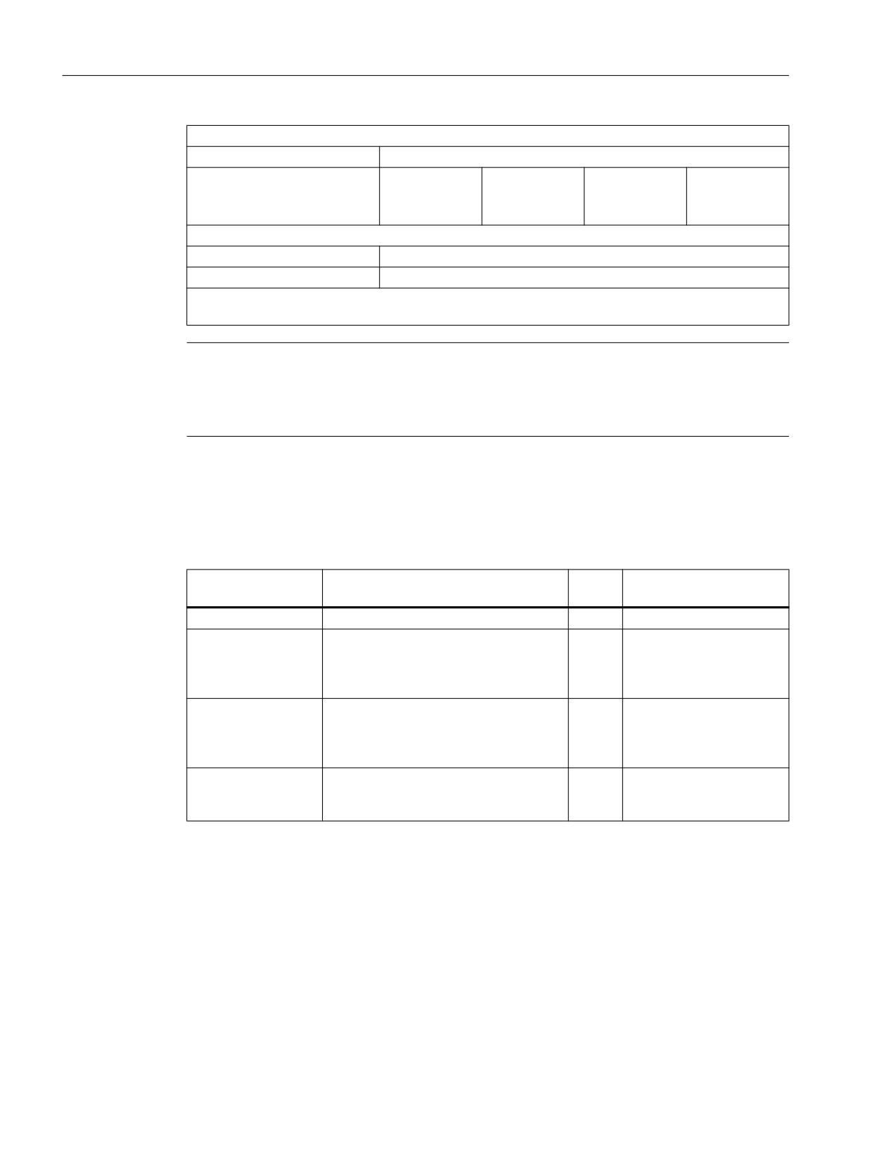
Dimension drawing
Image 5-4
Dimension drawing for handwheel connection module
5.5
Technical data
Safety
Safety class
III according to EN60204-1
Degree of protection according
IP00
to EN 60529
Approvals
CE / cULus
Handheld units
Manual, 03/2016, 6FC5397-1AP40-5BA3
149
Handwheel connection module
5.6 Accessories
Electrical data
Input voltage
24 VDC
Power consumption, max.
Board:
Handwheels:
Lamps:
Total:
6.2 W
2 x 0.9 W
14.4 W
22.4 W
(6 x 2.4 W) *)
Mechanical data
Dimensions (W°x H°x°D)
234 x 137 x 40 mm
Weight
Approx. 820 g
*) The outputs for the illuminated pushbuttons (X53/X54) can have a max. permissible current of 0.3 A.
However, the total current consumption of the components must not exceed 1.0 A (24 W).
Note
Information about the climatic and mechanical environmental conditions is contained in the
associated section under:
"General notes and interconnection" → "Operational planning".
5.6
Accessories
The following accessories are available for the handwheel connection module:
Component
Description
Quanti-
Article number
ty
Cable for handwheel
Length: < 5 m
1
6FX8002-2CP00-1Ax0
Feedrate override
Feedrate / rapid traverse override, solid-
1
6FC5247-0AF13-1AA0
rotary switch
state rotary switch 1x23G, T=32, cap,
button, pointer, rapid traverse and fee-
drate dials
Spindle override
Spindle / rapid traverse override, solid-
1
6FC5247-0AF12-1AA0
rotary switch
state rotary switch 1x16G, T=24, cap,
button, pointer, rapid traverse and spin-
dle dials
Cable set
For additional control devices of the ma-
60
6FC5247-0AA35-0AA0
chine control panels
Length: 500 mm
Handheld units
150
Manual, 03/2016, 6FC5397-1AP40-5BA3
Index
Parameterization, 46
PLC, 45
A
Power consumption, 56
Rotary override switch, 11
Activate keyboard, 99
HT 8
ASCII code
Control cabinet installation, 89
HT 2, 49
CPF menu, 111
Dimensions, 113
Display, 77
C
Displaying/hiding the traversing keys, 109
Connection kit
Emergency Stop button, 78, 113
Mini handheld unit, 124, 132
Enabling button, 79
Control cabinet installation
Key labeling, 111
HT 8, 89
Membrane keyboard, 78
Power consumption, 113
Thin Client, 73
D
Traversing keys, 110
User keys, 110
Deactivate keyboard, 99
HT 8
Display
Activating, deactivating the virtual keyboard, 98
HT 8, 77
Configuring the traversing keys, 99
Key labeling, 104
LED display on user keys, 106
E
oem_sljk_deu.ts, 101
Emergency Stop button
slguiconfig.ini, 98
HT 2, 57
sljkconfig.ini, 100
HT 8, 78, 113
Enabling button
HT 8, 79
K
Keys
HT 2, 46
H
Handwheel
Handheld, 135
M
Handwheel connection module
Membrane keyboard
Dimensions, 150
HT 8, 78
PROFIBUS DP, 143
Mini handheld unit
HT 2
Connection kit, 124, 132
ASCII code, 49
Dimensions, 123, 131
Control cabinet installation, 27
Dimensions, 57
Display, 10
O
Emergency stop button, 11
Emergency Stop button, 57
oem_slck_deu.ts, 104
Enabling button, 11
oem_sljk_deu.ts, 102
Handwheel, 11
Keyboard, 10
Key-operated switch, 13
Keys, 46
Handheld units
Manual, 03/2016, 6FC5397-1AP40-5BA3
151
Index
P
Parameterization
HT 2, 46
PLC
HT 2, 45
PROFIBUS DP
Handwheel connection module, 143
S
slckcpf.ini, 107
T
Thin Client
HT 8, 73
Touch screen
HT 8, 77
HT 8, 77
Handheld units
152
Manual, 03/2016, 6FC5397-1AP40-5BA3

Machine control panel: MCP
1
310C PN
Machine control panel: MCP
2
310 PN
Machine control panel: MCP
3
310
SINUMERIK
Machine control panel: MCP
4
483C PN
SINUMERIK 840D sl
Machine control panels
Machine control panel: MCP
5
483 PN
Machine control panel: MCP
6
483
Manual
Machine pushbutton panel:
7
MPP 310 IE H
Machine pushbutton panel:
8
MPP 483 IE
Machine pushbutton panel:
9
MPP 483
10
MCP Interface PN
Electronic handwheels
11
12
Rotary override switch
Valid for: SINUMERIK 840D sl / 840DE sl control
03/2016
6FC5397-1AP40-5BA3
Table of contents
1
Machine control panel: MCP 310C PN
11
1.1
Description
11
1.2
Operator control and display elements
13
1.2.1
Front
13
1.2.2
Rear side
15
1.3
Interfaces
16
1.3.1
Overview
16
1.3.2
Description
17
1.3.3
Input / output images
21
1.4
Mounting
23
1.5
Connecting
24
1.6
Maintenance and Service
25
1.7
Technical data
26
1.8
Accessories and spare parts
27
2
Machine control panel: MCP 310 PN
29
2.1
Description
29
2.2
Operator controls and indicators
31
2.2.1
Front side
31
2.2.2
Rear side
33
2.3
interfaces
34
2.3.1
Overview
34
2.3.2
Description
35
2.3.3
Input / output images
35
2.4
Mounting
38
2.5
Connecting
39
2.6
Maintenance and Service
40
2.7
Technical data
41
2.8
Accessories and spare parts
42
2.8.1
Overview
42
2.8.2
Labeling the slide-in labels
43
2.8.3
Inserting the slide-in label "Part1"
48
3
Machine control panel: MCP 310
53
3.1
Description
53
3.2
Operating and display elements
54
3.2.1
Front side
54
3.2.2
Rear side
55
Machine control panels
Manual, 03/2016, 6FC5397-1AP40-5BA3
3
Table of contents
3.3
Interfaces
56
3.3.1
Overview
56
3.3.2
Settings via DIP switch S3
57
3.3.3
Input / output images
57
3.4
Mounting
61
3.5
PROFIBUS communication
62
3.5.1
Overview
62
3.5.2
Prerequisites
62
3.5.3
Functions of the machine control panel
63
3.5.4
Configuring the DP slave MCP
63
3.5.5
Linking the DP slave MCP
66
3.6
Maintenance and Service
68
3.7
Diagnostics
69
3.7.1
LED displays
69
3.7.2
Output functions
69
3.7.3
Key test
71
3.8
Technical data
72
3.9
Accessories and spare parts
73
3.9.1
Overview
73
3.9.2
Labeling the slide-in labels
74
3.9.3
Using the slide-in label "Teil1"
79
4
Machine control panel: MCP 483C PN
83
4.1
Description
83
4.2
Operating and display elements
85
4.2.1
Front side
85
4.2.2
Rear side
88
4.3
Interfaces
89
4.3.1
Overview
89
4.3.2
Description
89
4.3.3
Input / output images
90
4.4
Mounting
93
4.5
Connecting
94
4.6
Maintenance and Service
95
4.7
Technical data
96
4.8
Accessories and spare parts
97
5
Machine control panel: MCP 483 PN
99
5.1
Description
99
5.2
Operator controls and indicators
101
5.2.1
Front side
101
5.2.2
Rear side
103
5.3
interfaces
104
5.3.1
Overview
104
Machine control panels
4
Manual, 03/2016, 6FC5397-1AP40-5BA3
Table of contents
5.3.2
Description
105
5.3.3
Input / output images
106
5.4
Mounting
109
5.5
Connecting
110
5.6
Maintenance and Service
110
5.7
Technical data
111
5.8
Accessories and spare parts
112
5.8.1
Overview
112
5.8.2
Membrane keyboard: Labeling the slide-in labels
113
6
Machine control panel: MCP 483
119
6.1
Description
119
6.2
Operating and display elements
120
6.2.1
Front side
120
6.2.2
Rear side
122
6.3
Interfaces
123
6.3.1
Overview
123
6.3.2
Settings via DIP switch S3
123
6.3.3
Input / output images
124
6.4
Mounting
127
6.5
PROFIBUS communication
129
6.5.1
Overview
129
6.5.2
Prerequisites
129
6.5.3
Functions of the machine control panel
130
6.5.4
Configuring the DP slave MCP
130
6.5.5
Linking the DP slave MCP
133
6.6
Maintenance and Service
135
6.7
Diagnostics
136
6.7.1
LED displays
136
6.7.2
Output functions
136
6.7.3
Key test
138
6.8
Technical data
139
6.9
Accessories and spare parts
140
6.9.1
Overview
140
6.9.2
Membrane keyboard: Labeling the slide-in labels
141
7
Machine pushbutton panel: MPP 310 IE H
147
7.1
Description
147
7.1.1
Overview
147
7.1.2
System features
147
7.1.3
Mechanical design
150
7.2
Operator controls and indicators
151
7.2.1
Overview
151
7.2.2
Description
153
7.2.2.1
Device front
153
Machine control panels
Manual, 03/2016, 6FC5397-1AP40-5BA3
5
Table of contents
7.2.2.2
Device rear side
154
7.3
Interfaces
156
7.3.1
Overview
156
7.3.2
Description
158
7.3.2.1
Control panel
158
7.3.2.2
COM board
159
7.3.2.3
User keys
160
7.3.2.4
Handheld unit connection HT 8
162
7.3.3
Connection elements for COM board, customer keys and handheld unit connection
165
7.3.4
Input / output images
166
7.4
Mounting
169
7.5
Connecting
173
7.5.1
MPP 310 IE H
173
7.5.2
Customer keys
175
7.5.3
Handheld unit connection HT 8 with emergency stop override
175
7.5.4
Circuits and wiring
179
7.6
Initialization
181
7.7
Maintenance and Service
183
7.8
Technical data
183
7.8.1
MPP 310 IE H
183
7.8.2
Input/output interface of individual wiring
184
7.9
Accessories and spare parts
186
7.9.1
Overview
186
7.9.2
Labeling the slide-in labels
187
7.9.3
Display elements and operator controls
192
8
Machine pushbutton panel: MPP 483 IE
195
8.1
Description
195
8.1.1
Overview
195
8.1.2
System features
196
8.1.3
Mechanical design
198
8.2
Operator controls and indicators
199
8.2.1
Standard versions
199
8.2.2
Special versions
201
8.2.3
Examples of assignment of free slots
204
8.2.4
Description
205
8.2.4.1
Device front
205
8.2.4.2
Device rear side
207
8.3
interfaces
209
8.3.1
Overview
209
8.3.2
Description
211
8.3.2.1
Control panel
211
8.3.2.2
COM board
213
8.3.2.3
Flat module customer keys
213
8.3.2.4
Connection for handheld units
216
8.3.3
Connection elements for COM board, customer keys and handheld unit connection
219
8.3.4
Input / output images
220
Machine control panels
6
Manual, 03/2016, 6FC5397-1AP40-5BA3
Table of contents
8.4
Mounting
224
8.5
Connecting
228
8.5.1
MPP 483 IE
228
8.5.2
Customer keys
230
8.5.3
Handheld unit connection with Emergency Stop override
230
8.5.4
Circuits and wiring
234
8.6
Initialization
235
8.7
Maintenance and Service
237
8.8
Technical data
237
8.8.1
MPP 483 IE
237
8.8.2
Input/output interface of individual wiring
238
8.9
Accessories and spare parts
241
8.9.1
Overview
241
8.9.2
Labeling the slide-in labels
242
8.9.3
Expansion panel
245
8.9.4
Display elements and operator controls
249
9
Machine pushbutton panel: MPP 483
251
9.1
Description
251
9.1.1
Overview
251
9.1.2
System features
252
9.1.3
Mechanical design
254
9.2
Operating and display elements
256
9.2.1
Standard versions
256
9.2.2
Special versions
259
9.2.3
Examples of assignment of free slots
264
9.2.4
Description
266
9.2.4.1
Device front
266
9.2.4.2
Device rear side
268
9.3
Interfaces
271
9.3.1
Overview
271
9.3.2
Description
272
9.3.2.1
Control panel
272
9.3.2.2
COM board
275
9.3.2.3
User keys
275
9.3.2.4
Handheld unit connection HT 6
279
9.3.2.5
Handheld unit connection HT 2/8
281
9.3.3
Connection elements for COM board, customer keys and handheld unit connection
284
9.3.4
Settings via DIP switch
285
9.3.5
Input / output images
286
9.4
Mounting
291
9.5
Connecting
296
9.5.1
MPP 483
296
9.5.2
COM board
300
9.5.3
Handheld unit connection HT 8 with emergency stop override
300
9.5.4
Customer keys
303
9.5.5
Circuits and wiring
305
Machine control panels
Manual, 03/2016, 6FC5397-1AP40-5BA3
7