SINUMERIK 840D sl Hardware. Manual (2011-2020) - page 6
PCU 50.5
15.6 Commissioning
5. You can also use the cursor keys <→> (right) and <←> (left) to reach other setup menu
items.
6. Press the <Esc> button (<Alarm Cancel> button) to go to the "Exit" menu.
(This menu can also be reached by pressing and holding down the <→> (right) cursor key.)
7. Press the <Input> key to quit the setup menu.
8. Press the <Input> key to confirm your decision to exit BIOS Setup with "Yes".
The system then starts (see Section: "BIOS startup").
6KLIW NH\
6+,)7
$/$50
(VFDSH NH\
&$1&(/
,QSXW NH\
,1387
SUHVV
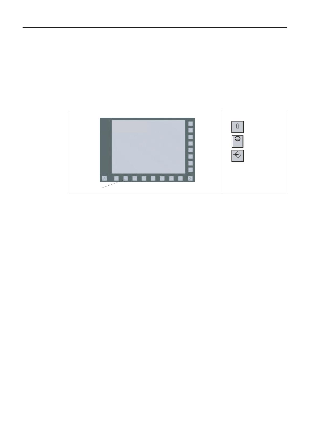
) ! WR HQWHU %,26 VHWXS
) NH\
Image 15-19 Using the BIOS Setup via an operator panel front
15.6.2
System start
More information on the system start can be found in the manual "IM8 start-up of PCU base
software."
15.6.3
Switching off / reset
Exiting Windows
To close the operating system, select "Start" → "Shut down".
This ensures that the system and operating system can be restarted without any problems.
Switching off the PCU
Once you have closed and shut down Windows, the power supply module of the PCU is still
switched on.
If you also want to switch off the power supply, tip the PCU's On/Off switch to the "0" position.
Operator panels
248
Manual, 03/2016, 6FC5397-1AP40-5BA3

PCU 50.5
15.6 Commissioning
Reset
The PCU does not have a special reset button to restart the system.
If you want to enforce a system restart, use the On/Off switch to switch your PCU off and on
again.
CAUTION
Residual currents can cause injuries
When undertaking service work (opening the PCU), also withdraw the line connector to the
24 V power supply. This is the only way of totally de-energizing the unit!
15.6.4
Touchscreen calibration
If you connect a touch panel (e.g. TP 015A) to the PCU, you must recalibrate the touch screen
of this operator panel front. The touch software, required for the calibration, is included in the
PCU base software.
Procedure
A functioning "touch panel with PCU 50.5" is required.
Note
If you take too long to calibrate the device, the whole process is canceled by a "timeout" and
you have to start again from the beginning.
1. Boot up the system in service mode.
2. Start the SINUMERIK desktop (password-protected).
Operator panels
Manual, 03/2016, 6FC5397-1AP40-5BA3
249
PCU 50.5
15.6 Commissioning
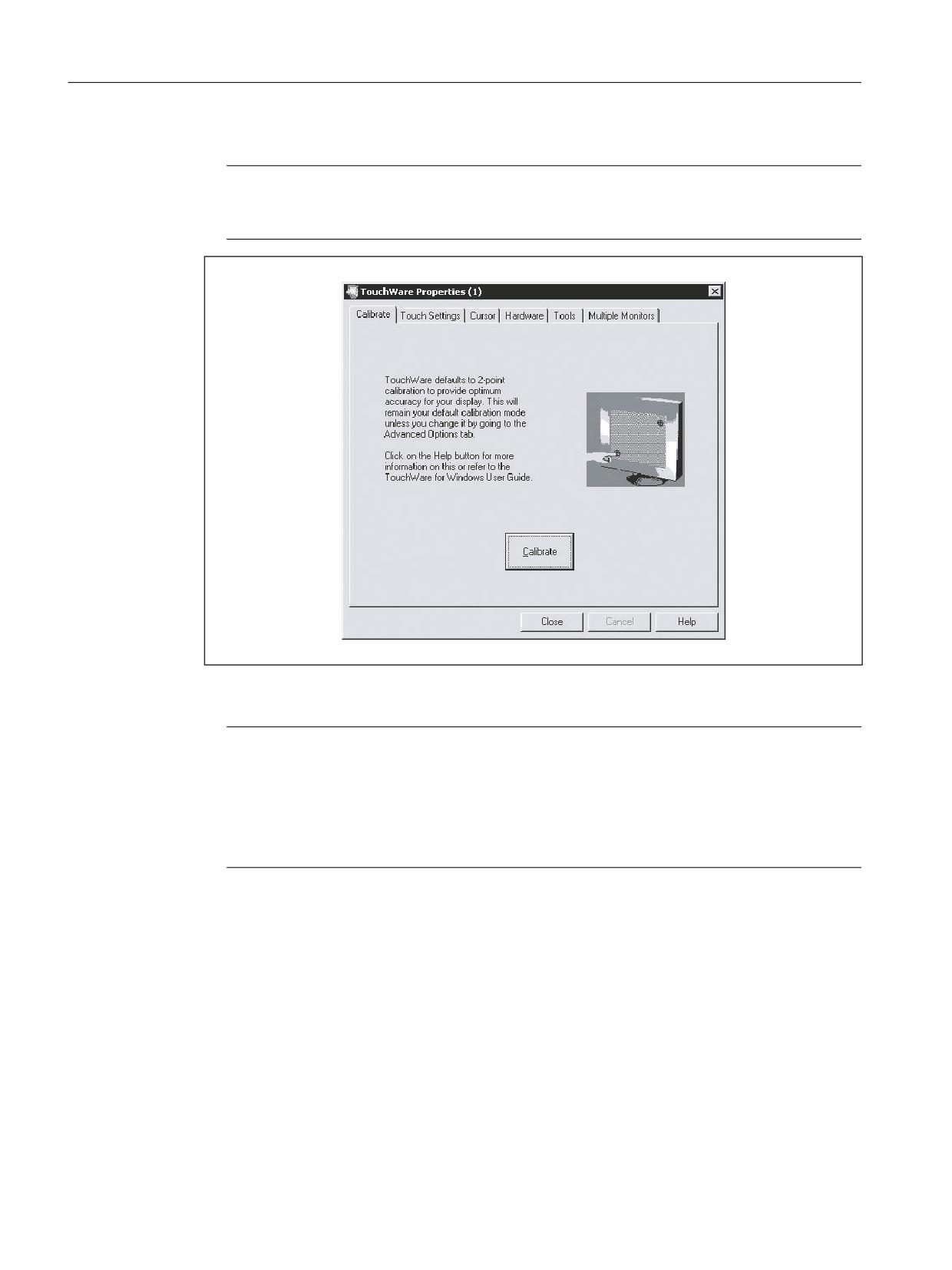
3. Call the calibration menu via "Start" → "Programs" → "Touchware" → "UPDD" (see figure).
Note
On the TP 015A the default calibration is centrosymmetric to the center point. This means
that you must press the top right of the screen to activate the "Start" button (bottom left).
Image 15-20 Menu for touch screen calibration (Touchware version 5.64 SR3)
Note
Depending on the software version and setting, the screen can include 2, 4 or 5 calibration
points.
You can toggle between 2 and 5 points (Touchware version 5.63 SR3) or between 2 and
4 points (Touchware version 5.64 SR3) from the menu "Tools" → "Options" → "Advanced"
→ "Style".
Operator panels
250
Manual, 03/2016, 6FC5397-1AP40-5BA3
PCU 50.5
15.6 Commissioning
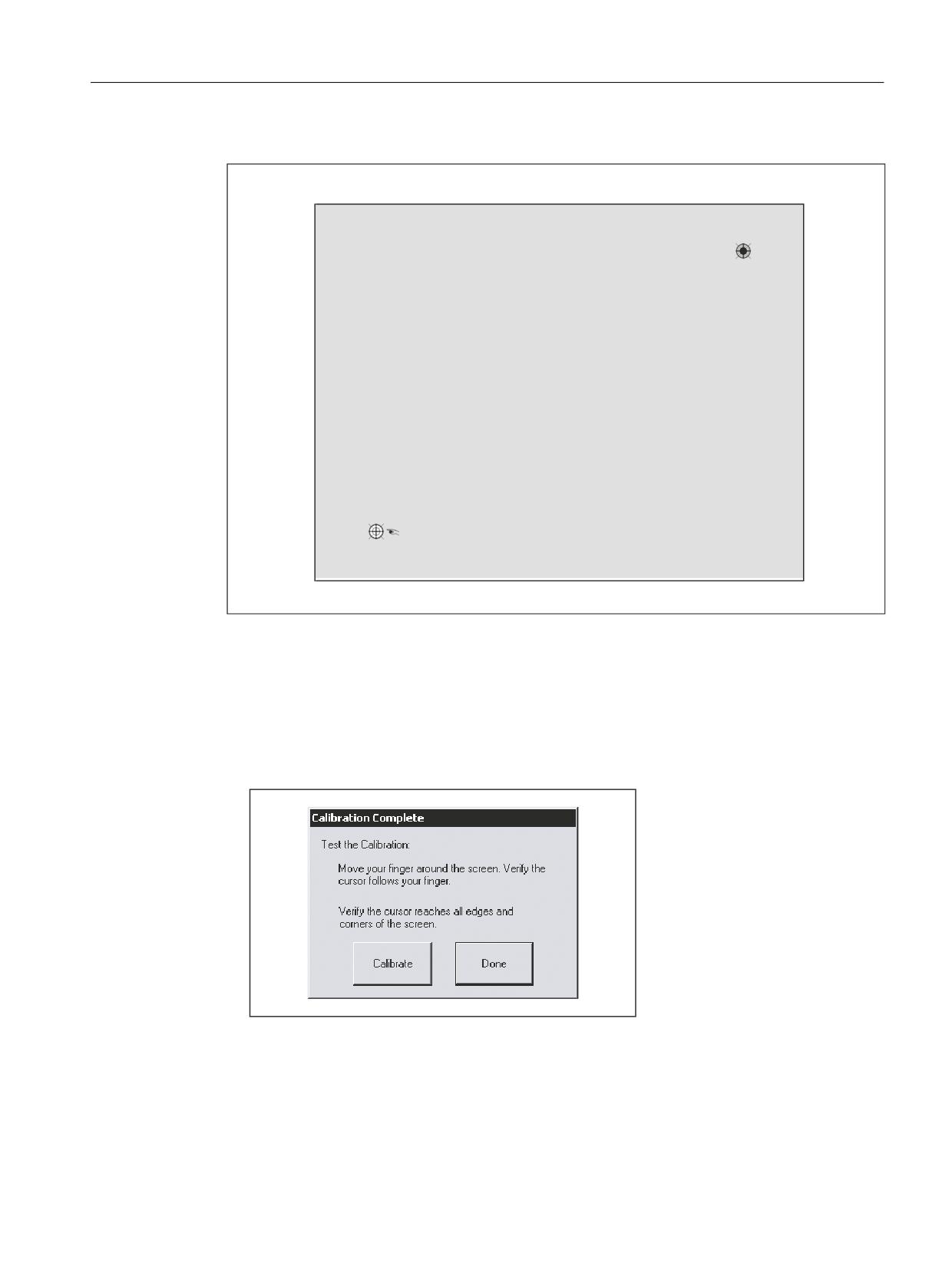
4. Press the "Calibrate" button. The following display appears on the screen:
Image 15-21 Calibration screen
5. Using the tip of one finger, touch the calibration point indicated by the hand symbol as
accurately as possible for as long as the "Hold" prompt is displayed. The "Hold" prompt
disappears after a few seconds and the hand moves to the next calibration point.
6. Repeat the instructions in step 5 until all available points have been calibrated.
Once the calibration point parameters have been saved, the following menu
appears:
Image 15-22 Test menu
7. To test the calibration values, move your finger around the screen and observe the cursor.
If necessary, recalibrate using "Calibrate".
8. Exit the calibration menu via "Done" → "Close".
Operator panels
Manual, 03/2016, 6FC5397-1AP40-5BA3
251

PCU 50.5
15.6 Commissioning
15.6.5
Operation with an S7-CPU (without NCU)
Application range
MCP communication is understood to be the transfer of I/O images to the following
components:
● two machine control panels
● one HHU
● two direct key units of an OP
The machine control panel signals are communicated on SINUMERIK systems using the FB1
(MCP communication). On more complex systems, the FB9 is used to carry out the M:N
switchover. The parameters are filed in DB7 and can be changed by the FB9. Since these
blocks are not available in the SIMATIC environment, the FB9 Proxy assumes these tasks.
Preconditions
It is a requirement that a DB19 is available on the installed S7-CPU in accordance with
SINUMERIK specifications: PCU 50.5 with HMI application
The FB9 proxy only functions if the MCP client (mcpdrv) is also running.
Creating DB19 in the PLC user program
The user must create the DB19 for the PLC user program. If the DB19 is copied from an existing
PLC project to a NCU, it may be that it is not saved during the series machine startup.
The DB19 copied from the existing SINUMERIK project was generated by the basic program
and a corresponding generic bit set. This bit is evaluated during a series machine startup and
the block would NOT be saved, as it has been generated by the system.
A new data block (DB19) is created via STEP 7 with the following structure:
STRUCT: Array [-32768..-32371] type: BYTE
Address
Name
Type
Start value
0.0
STRUCT
+0.0
DB_VAR
ARRAY(-32768 ... -32371)
+1.0
BYTE
=398.0
END_STRUCT
A flag is not set for blocks created by the user, i.e. not created by the system, and the block
is always saved during the series machine startup.
Operation with a PCU 50.5 and SINUMERIK Operate
The two utility programs, FB9 proxy and MCP Client, are not started automatically by the
system on the PCU 50.5. To start the two utilities, changes are made in the following files:
systemconfiguration.ini file with the following contents:
Operator panels
252
Manual, 03/2016, 6FC5397-1AP40-5BA3
PCU 50.5
15.6 Commissioning
In the [processes] section, the MCP Client and the FB9 Proxy need to be entered after the CP
entry.
[processes]
PROC000= image:=cp_840di, process:=CP_840di, backg3round:=true
PROC001= image:=slsmhmihost, process:=SlHmiHost1, deferred:=true
PROC002= image:=mcpdrv, process:=mcpdrv, backg3round:=true
PROC003= image:=fb9proxy, process:=fb9proxy, backg3round:=true
15.6.6
Configuring the 'fb9_proxy.ini' file
Configuring the fb9_proxy.ini file
Example of configuration file when supplied:
[PLC]
;# Set GET_IP_BY_HMI to '0', if you want a static connection to PLC
;# with specified IP address
;# otherwise FB9-Proxy tries to determine IP address and CP interface
;# from mmc.ini of HMI
;GET_IP_BY_HMI = 1
;# if GET_IP_BY_HMI is set to '1' the following key 'IP ADDRESS'
;# has no effect
;# otherwise this key determines the static IP address of the PLC
;IP-ADDRESS = 192.168.214.241
;# if GET_IP_BY_HMI is set to '1' the following key ' CP-INTERFACE '
;# has no effect
;# otherwise this key determines the interface to the shared memory
;# of the CP software.
;# The key is useful to avoid collisions between FB9-Proxy and
;# the HMI. The CP software supports two shared memory interfaces.
;# Normally one interface is used by the HMI.
;# HMI Embedded and HMI sl use the interface with index 1.
;# So the FB9-Proxy uses by default the interface with index 2.
;# HMI Advanced uses the interface with index 2, so you have
;# to instruct the FB9-Proxy to use the interface with index 1.
Operator panels
Manual, 03/2016, 6FC5397-1AP40-5BA3
253
PCU 50.5
15.6 Commissioning
;CP-INTERFACE = 2
;# 2 bytes for PLC alarms
;ALARM = AB80
;# address of 2 bytes for life sign of fb9proxy
;LIFESIGN = AB82
;# cycle for transmission of life sign
;# (valid values between 200 and 2000 milliseconds)
;LIFECYCLE =
200
[MCP1]
;BUS-ADDRESS
= 6
;PROFILE = 0
;IN = EB0
;OUT = AB0
[MCP2]
;BUS-ADDRESS
= 6
;PROFILE = 0
;IN = EB64
;OUT = AB64
[HHU]
;BUS-ADDRESS
= ?
;PROFILE = 0
;IN = EB32
;OUT = AB32
[DCK1]
;BUS-ADDRESS
= 6
;PROFILE = 1
;IN = EB16
;OUT = AB16
[DCK2]
;BUS-ADDRESS
= 6
Operator panels
254
Manual, 03/2016, 6FC5397-1AP40-5BA3

PCU 50.5
15.6 Commissioning
;PROFILE = 1
;IN = EB48
;OUT = AB48
Connection to the PLC
In the [PLC] section, the "IP-ADDRESS" key specifies the IP address of the S7-CPU. A
connection is made to this PLC. This key is only evaluated if no IP address for the PLC is found
in the mmc.ini file.
The IP address of the S7-CPU can be set via GET_IP_BY_HMI : The operator can define
whether the IP address of the PLC is obtained from the mmc.ini or whether a static IP address
is defined.
GET_IP_BY_HMI = 1 → IP address is obtained from the mmc.ini.
GET_IP_BY_HMI = 0 → Static IP address is defined via fb9_proxy.ini.
The "LIFESIGN" key can be used to obtain a sign of life from the FB9 Proxy on the PLC.
The "ALARM" key indicates the location in the PLC to which the two alarm bytes should be
written. If this key does not exist, the alarm bytes are not transferred.
Triggering alarms
In contrast to the original FB9, it is not possible for the FB9 Proxy to trigger PLC alarms. The
user program on the SIMATIC CPU can decide whether or not alarms are triggered. When the
cause of the alarm has been remedied and this is detected by the FB9 Proxy, the relevant bit
is reset. If the alarms are acknowledged, the user program on the SIMATIC CPU can reset
the bits itself.
The alarms are entered in a byte array that can be transferred to the PLC. For this purpose,
the variable "ALARM" must be specified in the [PLC] section in the INI file. In the case of
transitional edges 0→1, the PLC user program can trigger the relevant alarms and, in the case
of transitional edges 1→0, it can cancel the alarms again. The alarm bits are written to AB30
and AB31 by default.
List of alarms that can be triggered by FB9 Proxy via MCP communication:
Alarm number
Alarm text
Bit
400260
Failure of machine control panel 1
AB30.0
400261
Failure of machine control panel 2
AB30.1
400262
Failure of manual operating device
AB30.2
400274
Direct key 1 failed
AB30.3
400275
Direct key 2 failed
AB30.4
410900
M:N - call waiting discontinued
AB31.0
410901
M:N - HMI 1 not responding to displacement
AB31.1
410902
M:N - HMI 1 is not going offline
AB31.2
410903
M:N - HMI 2 not responding to displacement
AB31.3
410904
M:N - HMI 2 is not going offline
AB31.4
Operator panels
Manual, 03/2016, 6FC5397-1AP40-5BA3
255

PCU 50.5
15.6 Commissioning
Alarm number
Alarm text
Bit
410905
M:N - HMI connection to assigned interface not available
AB31.5
410906
M:N - No sign of life on an HMI
AB31.6
References: Diagnostics Manual, PLC Alarms
Connection to additional components
The contents of the [MCP1], [MCP2], [HHU], [DCK1] and [DCK2] sections are configured in
exactly the same way and are used to configure the connections to the MCP/DCK devices:
If the "BUS-ADDRESS" key exists, a static connection is set up for the relevant device, i.e. no
dynamic request is required in the DB19 from an HMI application. If, however, a dynamic
request is made by an HMI application, the static connection is stopped and the dynamic
connection is made.
The "PROFILE" key indicates whether the standard parameter set or the direct key parameter
set should be used from the MCP_CLIENT.INI file.
Default:
PROFILE=0
for machine control panels and HHU
PROFILE=1
for direct keys
The "IN" key is used for addressing the inputs (key information) and indicates the address to
which information should be written.
The "OUT" key is used for addressing the outputs (LED information) and indicates the address
from which information is read.
The length of the inputs and outputs is determined directly by the device and, therefore, does
not need to be indicated. However, it is important to ensure that the addressing range is
adequately dimensioned, so that information does not overlap. For example, if the address
EB0 is configured for the MCP1 inputs and an HT 8 and an MCP483 are available for the M:N
switchover, the direct key inputs can only be configured from EB16. The MCP483 inputs are
14 bytes long.
Note
m:n configuration
If there is an HMI application in the system that supplies the m:n interface in the DB19, the
FB9 proxy dynamically establishes the connections with the names "MCP1" and "DCK1". In
this case, these two connections cannot be configured statically.
Therefore, use to the connections with the names "MCP2", "HHU" and "DCK2" instead. The
names have been selected with reference to the FB9 and are not linked to any semantics. The
connection with the name "HHU" can also be used for an MCP.
For addresses for the memory areas in the PLC, expressions such as EBx, ABx, MBx and
DBy.DBBx can be used. These are always byte addresses.
Operator panels
256
Manual, 03/2016, 6FC5397-1AP40-5BA3

PCU 50.5
15.7 Alarm, error and system messages
Examples:
IN = EB0
→ Inputs are written to the PLC from EB0.
OUT = DB100.DBB20
→ Outputs are read from DB100 from byte 20.
15.7
Alarm, error and system messages
15.7.1
Boot error messages
BIOS first performs a Power On Self Test (POST) within the boot routine to verify proper
operation of certain functional units of the PC. The boot sequence is interrupted immediately
if fatal errors occur.
If the test does not return an error, the BIOS initializes and tests additional functional units. In
this startup phase, the graphics controller is initialized and any error messages are output to
the screen.
The error messages output by the system BIOS are listed below. For information on error
messages output by the operating system or programs, refer to the corresponding manuals.
On-screen error messages
On-screen error message
Meaning / suggestions
Error - CMOS battery failed
The battery on the CPU module is defective or dead.
Contact your technical support team.
Error - SMART failure detected
Hard disk error: An error bound suggested by the manufacturer has
on HDD
been exceeded. The operation of the hard disk is not secure. The
hard disk must be replaced. Contact your technical support.
Error - Keyboard error
Check whether the keyboard is properly connected.
Keyboard faults Contact your technical support.
Notice: This error is not displayed per default, and must first be
activated in the setup.
No bootable device -- Please re-
Possible causes:
start system
● No operating system present
● Wrong drive addressed (disk in drive A/B)
● Incorrect active boot partition
● Incorrect drive entries in the setup
● Hard disk is not connected / defective
Error - Realtime clock has lost
Clock chip error.
power
Contact your technical support team.
Operator panels
Manual, 03/2016, 6FC5397-1AP40-5BA3
257

PCU 50.5
15.7 Alarm, error and system messages
15.7.2
BIOS beep codes
The essential POST codes are subsequently listed in the sequence in which they occur.
Contact Technical Support for information on all other POST codes.
Display
Description
Remedy
4DH
MonoTonicCounter Initial
MonoTonicCounter initialization
Service case
4EH
CPU Middle Initial
CPU initialization
Service case
4FH
Multi-processor Middle Initial
Multiprocessor initialization
Service case
50H
SMBUS Driver Initial
SMBUS driver initialization
Service case
51H
SMART-Timer Initial
SMART timer initialization
Service case
52H
RTC Initial
RTC initialization
Service case
53H
SATA Controller early initial
Preliminary initialization of the SATA
Service case
controller
54H
Setup SMM Control service
SSM control service
Service case
55H
Setup Legacy Interruput service
Setup Legacy Interrupt service
Service case
01H
CPU power on and switch to Protec-
Switch to protected mode
Service case
ted mode
02H
Patching CPU microcode
Load CPU microcode
Service case
03H
Setup Cache as RAM
Setup cache as RAM
Service case
04H
PCIE MMIO Base Address initial
Initialize PCIE
Service case
05H
CPU Generic Machine Status Regis-
Initialize CPU Machine Status Regis-
Service case
ter initial
ter
06H
Setup CPU speed
Define CPU speed
Service case
07H
Cache as RAM test
Perform RAM test on cache
Service case
08H
Tune CPU frequency ratio to maxi-
Set CPU frequency
Service case
mum level
09H
Setup BIOS ROM cache
Setup BIOS ROM cache
Service case
0AH
Enter Boot Firmware Volume
Call the boot firmware memory area
Service case
70H
Super I/O initial
Initializing the super I/O
Service case
71H
CPU Early Initial
Initialize CPU register
Service case
72H
Multi-processor Early initial
Multiprocessor initialization
Service case
73H
HyperTransport initial
Initialize hyper transport functionality
Service case
74H
PCIE MMIO BAR Initial
Initialize PCIE register
Service case
75H
North Bridge Early Initial
Initializing the North bridge
Service case
76H
South Bridge Early Initial
Initializing the South bridge
Service case
77H
PCIE Training
Training phase of the PCIE devices
Service case
79H
SMBUS Early Initial
Initializing the SM bus
Service case
41H
South bridge Serial Peripheral Inter-
Initializing the serial peripheral inter-
Service case
face initial
face in the South bridge
42H
Setup Reset service
Setup Reset service
Service case
43H
South bridge Serial GPIO initial
Initializing the serial GPIO
Service case
44H
Setup SMM ACCESS service
Setup SMM access service
Service case
45H
North bridge Middle initial
Initializing the North bridge
Service case
46H
Super I/O DXE initial
Initializing the super IO
Service case
47H
Setup Legacy Region service
Setup service legacy area
Service case
Operator panels
258
Manual, 03/2016, 6FC5397-1AP40-5BA3

PCU 50.5
15.7 Alarm, error and system messages
Display
Description
Remedy
48H
South Bridge Middle Initial
Initializing the South bridge
Service case
49H
Identify Flash device
Identify the FLASH type
Service case
4AH
Fault Tolerant Write verification
Testing the write error tolerance
Service case
4BH
Variable Service Initial
Initialization of the variable service
Service case
4CH
Fail to initial Variable Service
Error when initializing the variable
Service case
service
26H
Dispatch option ROMs
Calling the legacy option roms
Service case
27H
Get boot device information
Determining the boot device informa-
Service case
tion
HD-Lock active
HD interlocking not released
Release lock: Set HD-lock to "Op-
erating".
28H
End of boot selection
Boot selection exited
Service case
29H
Enter Setup Menu
Call in setup
Service case
2AH
Enter Boot manager
Call boot manager
Service case
2BH
Try to boot system to OS
Booting the OS
Service case
2CH
Shadow Misc Option ROM
Copying the legacy option ROM to the
Service case
RAM
2DH
Save S3 resume required data in
Prepare RAM for the operating state
Service case
RAM
S3
2EH
Last Chipset initial before boot to OS
Final chipset initialization before the
Service case
OS boot
2FH
Start to boot Legacy OS
Boot legacy OS
Service case
30H
Start to boot UEFI OS
Boot UEFI OS
Service case
31H
Prepare to Boot to Legacy OS
Preparation for booting the legacy OS
Service case
32H
Send END of POST Message to ME
Exit the boot service
Service case
via HECI
33H
Last Chipset initial before boot to
Final chipset initialization before the
Service case
Legacy OS.
legacy OS boot
34H
Ready to Boot Legacy OS.
Call to boot the OS
Service case
35H
Fast recovery start flash
Starting the BIOS recovery function
Service case
F9H
No Boot Device
No BOOT device found
Service case
FBH
UEFI Boot Start Image
Booting from a UEFI image
Service case
FDH
Legacy 16 boot entry
Start legacy 16 boot
Service case
FEH
Try to Boot with INT 19
Booting with INT 19
Service case
E5H
System wakeup from S5
Reboot from operating state S5
Service case
10H
Enter Boot Device Selection entry
Phase boot device selection
Service case
11H
Install Hotkey service
Installation of the hotkey service
Service case
12H
Alert Standard Format Initial
Initialize alert standard format
Service case
13H
PCI enumeration
Enumerate PCI bus
Service case
14H
PCI resource assign complete
Assign PCI resources
As a test, disable HW compo-
nents in setup or remove expan-
sion modules that have been in-
stalled.
15H
PCI enumeration complete
PCI enumeration completed
Service case
Operator panels
Manual, 03/2016, 6FC5397-1AP40-5BA3
259

PCU 50.5
15.7 Alarm, error and system messages
Display
Description
Remedy
16H
Keyboard Controller, Keyboard and
Initialization of keyboard and mouse
Run a test by replacing the key-
Mouse initial
board/mouse
17H
Video device initial
Initialize the graphic interface
Service case
18H
Error report device initial
Initialize standard error output
Service case
19H
USB host controller initial
Initialize USB host controller
Service case
1AH
USB BUS driver initial
Initialize USB bus driver
Service case
1BH
USB device driver initial
Initialize USB device driver
Service case
1CH
Console device initial fail
Initializing the error of the console
Service case
1DH
Display logo or system information
Display logo or system information
Service case
1EH
IDE controller initial
Initializing the IDE controller
Service case
1FH
SATA controller initial
Initializing the SATA controller
Service case
20H
Super IO controller initial
Initializing the super IO
Service case
21H
ISA BUS driver initial
Initializing the ISA bus driver
Service case
22H
Floppy device initial
Initializing the floppy interface
Service case
23H
Serial device initial
Initializing the serial interface
Service case
24H
IDE device initial
Initializing the IDE interface
Service case
25H
AHCI device initial
Initializing the AHCI interface
Service case
56H
Relocate SMM BASE
Reassign SMM basis
Service case
57H
SMI test
Test SMI
Service case
58H
VTD Initial
Initialize the I/O virtualization (VTD)
Service case
59H
Legacy BIOS initial
Legacy BIOS initialization
Service case
5AH
Legacy interrupt function initial
Legacy interrupt initialization
Service case
5BH
ACPI Table Initial
ACPI tables initialization
Service case
5CH
Setup SB SMM Dispatcher service
SMM dispatcher service
Service case
5DH
Setup SB IOTRAP Service
SouthBridge IOTRAP service
Service case
5EH
Build AMT (Active Management
Initializing the AMT (Active Manage-
Service case
Technology) Table
ment Technology) table
5FH
Processor Power Management Ini-
Initializing the processor power man-
Service case
tial
agement
60H
Host Embedded Controller Interfa-
Initializing the host embedded control-
Service case
ces Initial
ler interface
61H
Variable store garbage collection
Loading the variable memory
Service case
and reclaim operation
7AH
Clock Generator Initial
Initializing the clock generator
Service case
7BH
Internal Graphic device early initial,
First initialization of the graphic inter-
Service case
face
7CH
Host Embedded Controller Interfa-
Initializing the host embedded control-
Service case
ces Initial
ler interface
7DH
Watchdog timer initial
Initializing the watchdog timer
Service case
7EH
Memory Initial for Normal boot
Memory initialization during the PEI
Replace the memory modules
phase
7FH
Memory Initial for Crisis Recovery
Memory initialization for BIOS recov-
Replace the memory modules
ery
80H
Simple Memory test
Memory test
Replace the memory modules
Operator panels
260
Manual, 03/2016, 6FC5397-1AP40-5BA3

PCU 50.5
15.7 Alarm, error and system messages
Display
Description
Remedy
81H
Trusted Execution Technology func-
Initializing the Trusted Execution
Service case
tion early initial
Technology
82H
Start to use Memory
Start memory use
Service case
83H
Set cache for physical memory
Use cache as physical memory
Service case
84H
Recovery device initial
Initialize the device for BIOS recovery
Service case
85H
Found Recovery image
BIOS recovery image found
Service case
86H
Recovery image not found
BIOS recovery image not found
Check whether the BIOS recov-
ery image exists on the recovery
medium (e.g. USB FlashDrive).
87H
Load Recovery Image complete
Load BIOS recovery image exited
Service case
88H
Start Flash BIOS with Recovery im-
Starting with flash BIOS recovery im-
Service case
age
age
89H
Loading BIOS image to RAM
Copy BIOS image to RAM
Service case
8AH
Loading Driver Execution Environ-
Load Driver Execution Environment
Service case
ment (DXE) core
(DXE) program
8BH
Enter DXE core
Start DXE program
Service case
Special codes
The BIOS does not generate any beep codes.
15.7.3
Status codes of the diagnostics display during the system power up
Table 15-7
Status codes of the diagnostics display during the system power up
LED H1
LED H2
7-segment
Status
display H1/H2
Orange
Orange
Output of the
After switching on the system
BIOS post co-
des
Orange
Off
After cycling the BIOS
Orange
Off
After starting Windows
1
0
Starting Windows
Loading of the device drivers
required by Windows
2
0
PCU hardware service
The PCU hardware service has
been started.
5
0
Network
Wait for network interfaces to
be ready
8
0
TCU support test step 1
Wait for FTP server to start
9
0
TCU support test step 2
Wait for TCU network boot proc-
ess and starting of the TCU
hardware service
A
0
TCU support test step 3
Wait for VNC server to start
Operator panels
Manual, 03/2016, 6FC5397-1AP40-5BA3
261
PCU 50.5
15.8 Technical data
LED H1
LED H2
7-segment
Status
display H1/H2
B
0
-
-
E
0
PCU-Basesoftware
General fault: see Windows
"Event Viewer"
15.7.4
Status codes of the diagnostics display during operation
Table 15-8
Status codes of the diagnostics display during operation
LED H1
LED H2
7-segment
Status
display H1/H2
Flashing
--
0
0
OK
green
Flashing red
--
Error:
1
0
Temperature alarm
Housing or CPU temperature;
temperature above limit value
(SOM error)
2
0
Fan alarm
Housing or CPU: Low fan
speed or fan failure (SOM error)
3
0
Hard disk alarm
S.M.A.R.T hard disk error
6
0
VNC server failure or VNC serv-
er service stopped
15.7.5
Status codes of the diagnostics display during the shutdown process
Table 15-9
Status codes of the diagnostics display during the shutdown process
LED H1
LED H2
7-segment
Status
display H1/H2
Flashing red/
--
5
0
Shutdown in progress
green
15.8
Technical data
15.8.1
PCU 50.5
Safety
Safety class
I (SELV) according to EN 61140
Degree of protection according to
IP 20
EN 60529
Operator panels
262
Manual, 03/2016, 6FC5397-1AP40-5BA3
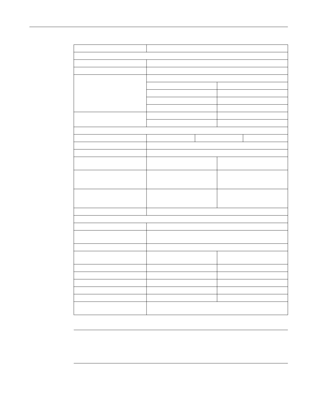
PCU 50.5
15.8 Technical data
Approvals
CE / cULus
Electrical data
Input voltage
24 VDC (20.4 V ... 28.8 V)
Input current
max. 8 A (starting current: max. 14 A at max. 30 ms)
Max. current output
USB external, each 0.5 A (in total: 1.2 A)
3.3 V
2 A
5 V
2 A
12 V
0.3 A
-12 V
0.05 A
Power consumption
PCU basic unit
PCI slots
typ. 48 W (at 55° C)
max. 15 W 1)
Mechanical data
Dimensions
Width: 297 mm
Height: 267 mm
Depth: 82 mm
Weight
approx. 4.5 kg
Slot 1/2:
Card length, max. 185 mm (measured without the slot plate)
Mechanical environmental condi-
Operation
Transport
tions
(in transport packaging)
Vibratory load
10 - 58 Hz: 0.075 mm
5 - 9 Hz: 6.2 mm
58 - 200 Hz: 9.8 m/s2
9 - 200 Hz: 19.6 m/s2
DIN IEC 60068-2-6
DIN IEC 60068-2-6
Shock load
50 m/s2, 30 ms
300 m/s2, 6 ms
18 shocks
18 shocks
DIN IEC60068-2-27
DIN IEC60068-2-27
Noise
< 55 dB (A) according to EN ISO 7779
Climatic environmental conditions
Heat dissipation
Open-circuit ventilation
Condensation, spraying water,
Not permitted
and icing
Supply air
Without aggressive gases, dusts and oils
Operation
Transport
(in transport packaging)
Applicable standards
DIN IEC 60068-2-1
DIN IEC 60068-2-2 / -2-14
Climate class
3K5
1K3 / 2K4
Temperature limits
5 ... 55 °C 2)
-20 ... 60 ℃
Temperature change
Max. 10 K/h
Max. 18 K/h
Limits for relative humidity
5 … 80% at 25° C
5 … 95% at 25° C
Perm. change in the relative air
max. 0.1 %/min
humidity
1)
All of the slots must not exceed this total power.
Note
Information about the climatic and mechanical environmental conditions is contained in the
associated section under:
"General notes and interconnection" → "Operational planning".
Operator panels
Manual, 03/2016, 6FC5397-1AP40-5BA3
263
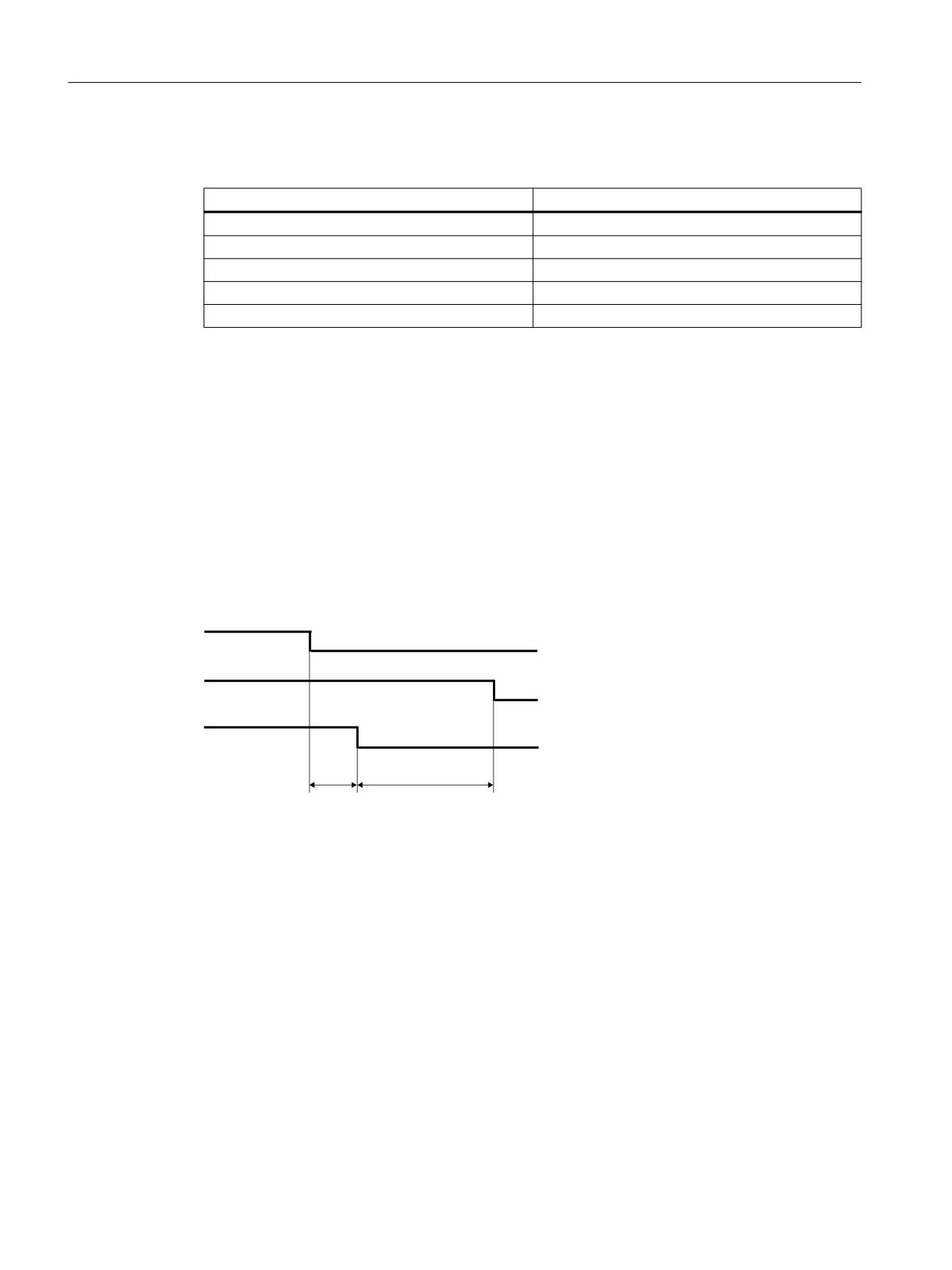
PCU 50.5
15.8 Technical data
15.8.2
Calculating the power
Component
Power
Base device with SSD
typ. 48 W / max. 76 W
USB expansion
max.
6 W
PCI/PCIe expansion
max. 15 W* (55°C)
Panel interface
max. 53 W *)
Total
max. 150 W
*)
with the onboard graphic disabled, max. 30 W (50°C)
Active power drawn at 24 V DC: max. 190 W / 210 W
15.8.3
Power failure detection
If the power supply fails for longer than 5 ms, a power supply failure signal is output using the
NAU signal. This signal is evaluated in the software, and transferred to the corresponding
application.
This means that e.g. data can be saved within 20 ms before the device hardware stops as the
result of a central reset (POWER GOOD end).
Power failure alarm schematic:
'&
9
32:(5 *22'
1$8
7
7
T1
preset time: min. 5 ms
T2
hold-up time: min. 20 ms (data save time)
Image 15-23 NAU signal of the 24 V DC power supply
Operator panels
264
Manual, 03/2016, 6FC5397-1AP40-5BA3

PCU 50.5
15.9 Spare parts
15.9
Spare parts
15.9.1
Overview
The following spare parts are available for the PCU 50.5:
Component
Article number
SSD 80 GB-SATA for Win7
6FC5247-0AF08-6AA0
for
6FC5210-0DF52-3AA0, 6FC5210-0DF53-3AA0
SSD 40 GB-SATA for WinXP
6FC5247-0AF08-5AA0
for
6FC5210-0DF52-2AA0, 6FC5210-0DF53-2AA0
Device fan
A5E02268846
Power supply fan
A5E02268847
Power supply 24 VDC / 150 W
A5E30947477
24 VDC power supply connector, 3-pin (5 units)
A5E03404000
CMOS battery 3 V Lithium CR 1/2 AA, PC
A5E00331143
Service module
A5E02518244
15.9.2
Replace
To maintain high system availability, we recommend the preventative replacement of those
PC components that are subject to wear. The table below indicates the intervals for this
replacement.
Component
Replacement interval
Hard disk drive SSD
> 5 years
Fan
5-7 years
CMOS backup battery
4/5 years
SSD
When compared to conventional hard disks, solid-state disks are significantly more rugged
against mechanical vibration and shock and are less sensitive to temperature.
However, due to the fact that the write cycles are limited, SSDs are wearing parts, i.e. write
access operations progressively wear the internal flash blocks. However, a long availability
can be achieved through preventive internal measures such as wear leveling, keeping reserve
blocks or error correction mechanisms.
In the industrial environment, a service life can be assumed that is higher than for conventional
mechanical hard disks and according to what we know today, is > 5 years.
The write load that occurs is a significant factor that influences the life expectancy.
Operator panels
Manual, 03/2016, 6FC5397-1AP40-5BA3
265
PCU 50.5
15.9 Spare parts
Fan
Fans are wearing parts. The fan speed is monitored and in the event of a failure an alarm is
issued.
Pollution is the main cause of fan failure. A visual inspection should be made as a first criterion
for replacement. If the fan has a high degree of accumulated dirt, it should be replaced. If no
pollution is present, then the usage time should be used as the criterion. The service life of the
fans also depends on the operating conditions (temperature, humidity, number of operating
hours per day), so that no fixed limits for all applications can be specified. In the field, under
average industrial conditions, a replacement interval of 5-7 years has proven itself.
Backup battery
Batteries are wearing parts. They should be replaced every 5 years to ensure that the device
functions permanently.
If an integrated PCI plug-in card is also supplied (central battery concept), preventive
replacement intervals are shortened to 4 years.
15.9.2.1
SSD module
Preparation
Disconnect the device from the line supply.
Note
The new module must be of the same type or a compatible successor.
Operator panels
266
Manual, 03/2016, 6FC5397-1AP40-5BA3
PCU 50.5
15.9 Spare parts
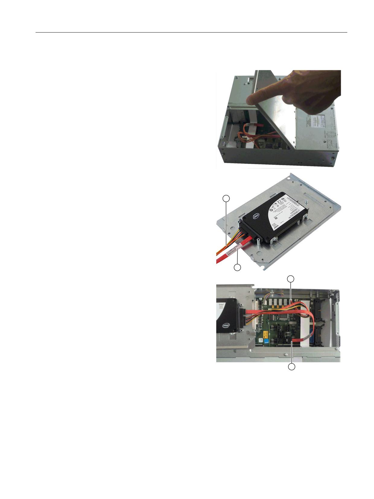
Replacing an SSD module
1. Remove the module racks of the SSD and
place this on the device.
2. Disconnect the power supply cable ③ and
the data cable ② from the main board and
replace the SSD module rack completely
(mounting plate with SSD).
Article number of the SSDs, see “Over-
view" (Page 265).
3. Connect the power supply cable ③ and
the data cable ② with the main board.
4. Mount the SSD module rack on the PCU.
Operator panels
Manual, 03/2016, 6FC5397-1AP40-5BA3
267
PCU 50.5
15.9 Spare parts
15.9.2.2
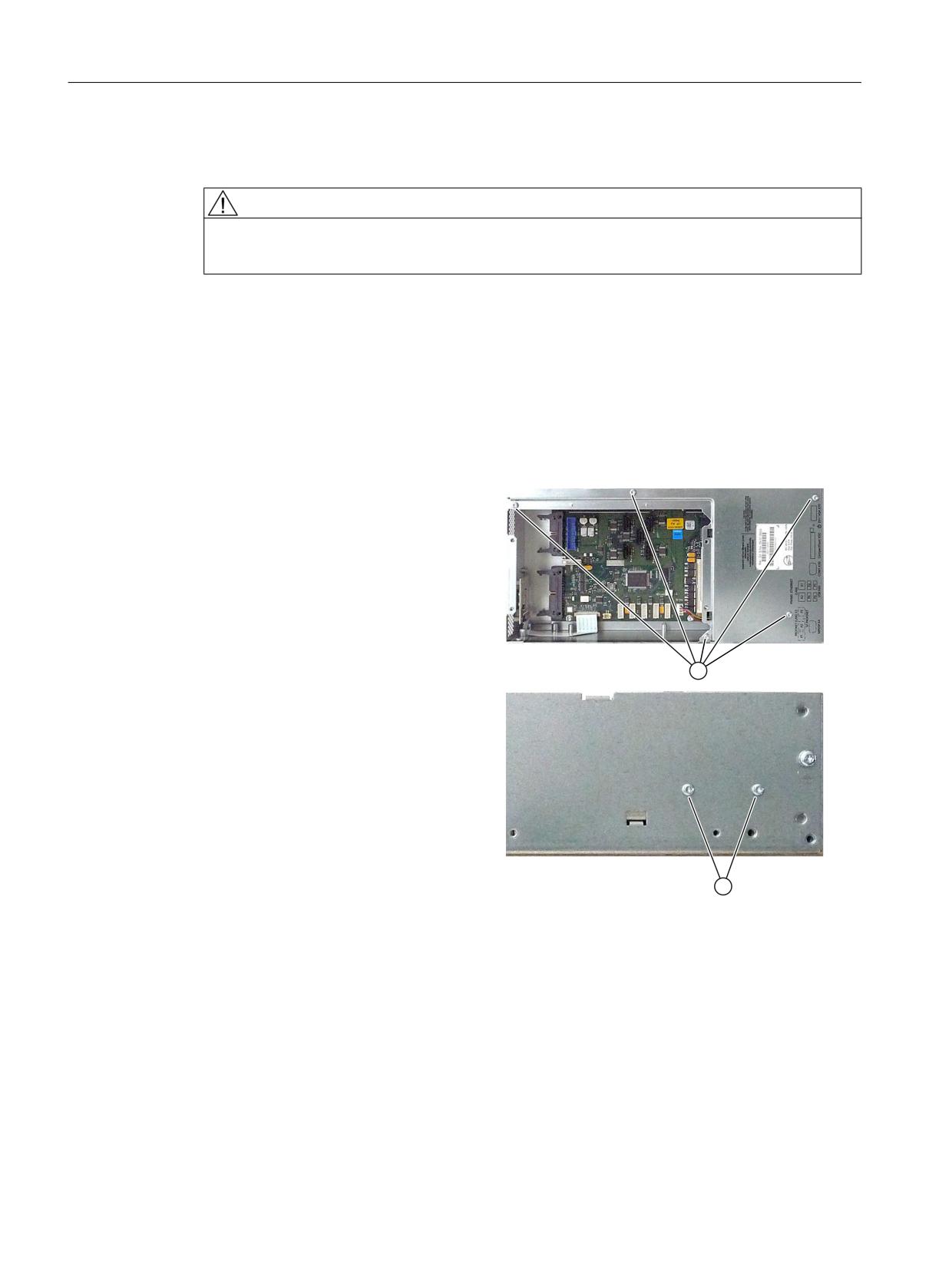
Power supply
WARNING
Unqualified tampering in the power supply causes severe injuries
Only authorized trained personnel are allowed to replace the power supply unit.
Preparations
1. Isolate the device from the line supply and disconnect all connecting cables from the device.
2. Remove the hard disk drive.
Removing the power supply
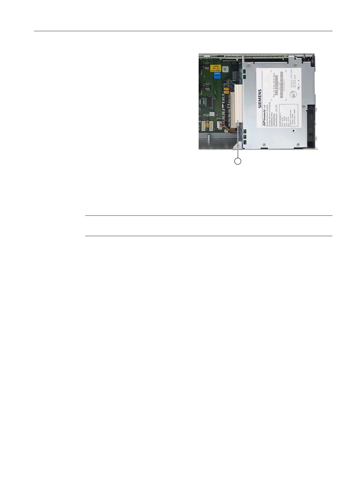
1. Loosen the screws ① and re-
move the power supply cover.
2. Remove the fixing screws ② of
the power supply.
Operator panels
268
Manual, 03/2016, 6FC5397-1AP40-5BA3
PCU 50.5
15.9 Spare parts
3. Withdraw the power supply plug
③ from the power supply.
4. Withdraw the power supply towards the top.
Installing the power supply
Install the new power supply in the reverse order.
Note
Observe the correct position of the power supply latches for upright bus PCBs.
15.9.2.3
Power supply fan
Preparations
1. Disconnect the device from the line supply.
2. Remove the power supply.
Operator panels
Manual, 03/2016, 6FC5397-1AP40-5BA3
269
PCU 50.5
15.9 Spare parts
Removing the power supply fan
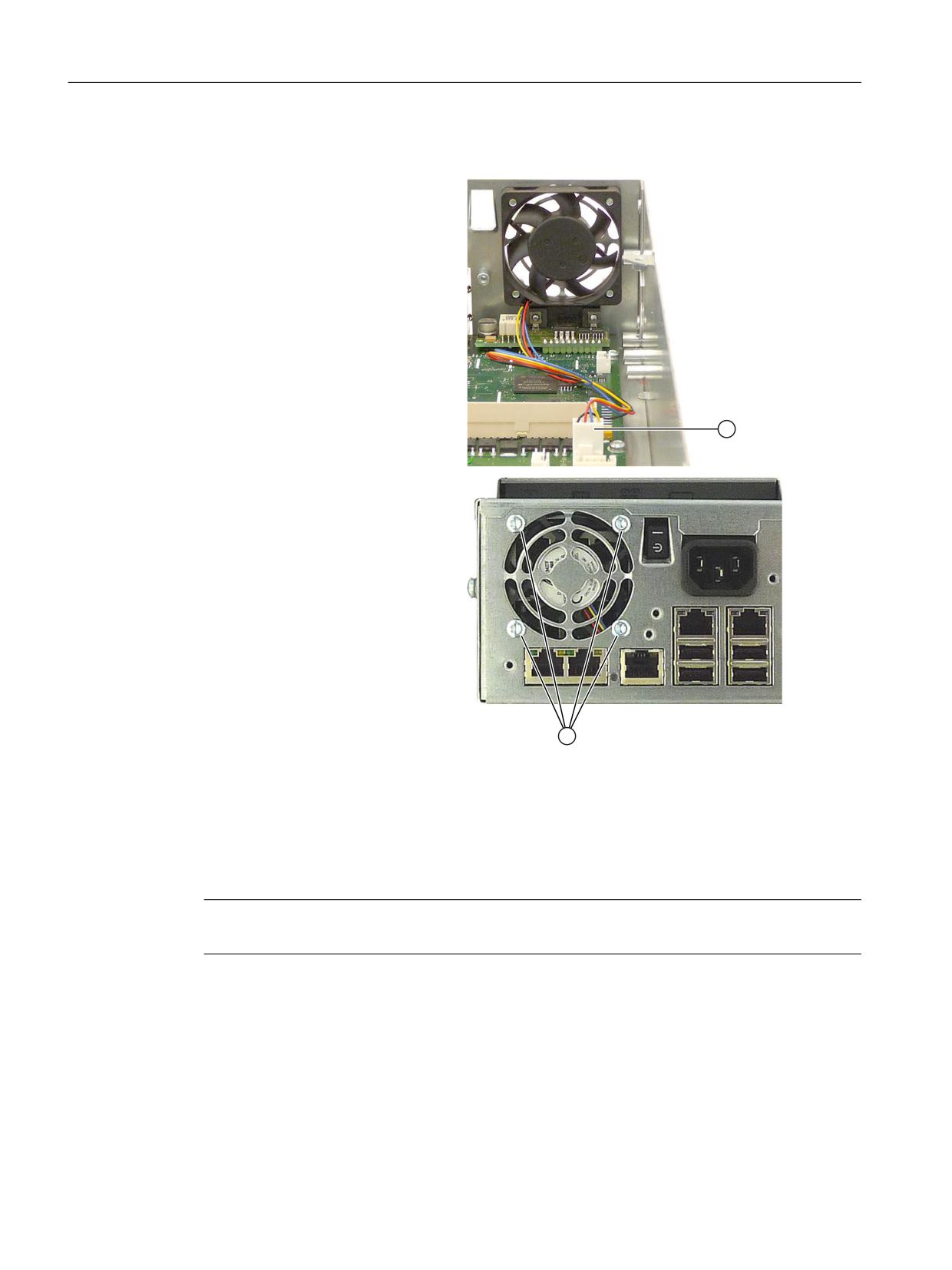
1. Withdraw the fan connector ①.
2. Loosen the four screws ① on the
enclosure.
3. Remove the fan from the enclosure.
Installing the power supply fan
Install the new fan in the reverse sequence. Ensure the correct installation position - fan blows
air towards the outside.
Note
Only a fan of the same type may be installed.
15.9.2.4
Device fan
Preconditions
1. Disconnect the device from the line supply.
2. Remove the covers from the service module and motherboard.
Operator panels
270
Manual, 03/2016, 6FC5397-1AP40-5BA3
PCU 50.5
15.9 Spare parts
Removing the device fan
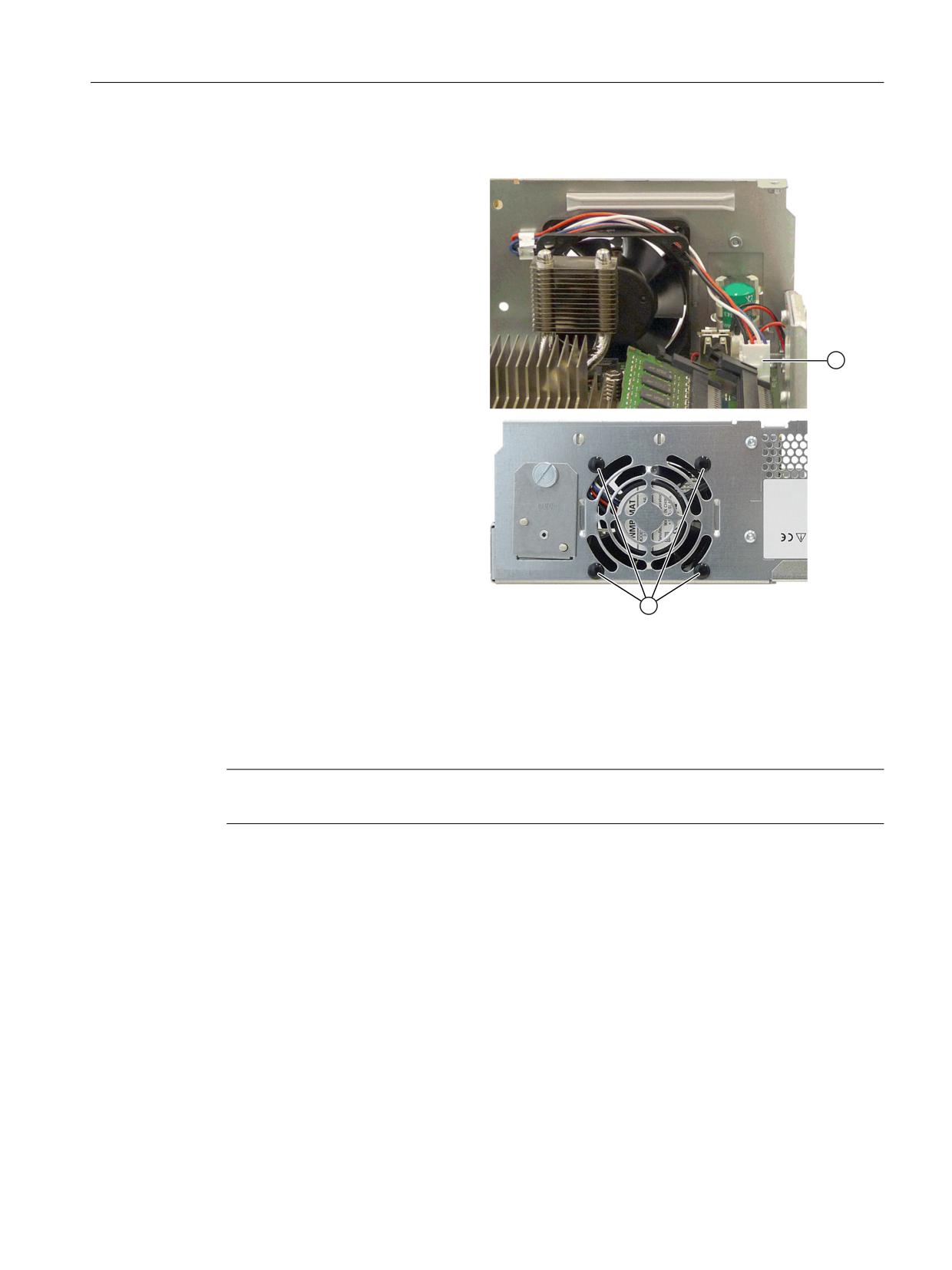
1. Withdraw the fan plug from the
motherboard.
2. Loosen the four two plastic rivets
on the enclosure.
3. Remove the fan from the enclosure.
Installing the device fan
Install the new fan in the reverse sequence. Ensure the correct installation position - fan blows
air towards the outside.
Note
Only a fan of the same type may be installed.
15.9.2.5
Backup battery
The backup battery supplies voltage not only to any plug-in cards used during operations but
also to the hardware clock once the device has been switched off. In addition to the time, the
BIOS settings of the device are also saved.
Operator panels
Manual, 03/2016, 6FC5397-1AP40-5BA3
271
PCU 50.5
15.9 Spare parts
To be noted before you replace the battery
NOTICE
Excessive voltages can damage plug-in cards
The lithium battery may only be replaced with an identical battery or with a type recommended
by the manufacturer. For the PCU 50.5, only use 3.0 V lithium batteries, as any plug-in cards
being used cannot tolerate any voltage exceeding 3.0 V.
WARNING
Risk of explosion and release of harmful substances!
For this reason, do not burn lithium batteries, do not solder on the cell body, do not open, do
not short circuit, do not reverse polarity, do not heat above 100° C, dispose of correctly, and
protect against direct sunlight, dampness and dew.
Disposal
NOTICE
Environmental contamination
Dispose of used batteries using the local connection point specifically set-up locally so that
they are correctly recycled or are disposed of as hazardous waste.
Preparation
Note
For the BIOS setting "Profile: Standard" the configuration data of the device is deleted when
the battery replacement takes more than 30 seconds.
For the BIOS setting "Profile: User" the configuration data of the device is retained; only the
date and time has to be reconfigured.
The content of the SRAM is lost if the battery replacement takes more than 30 seconds.
1. Note down the current settings of the BIOS Setup.
A list in which you can note down this information is found in the BIOS manual.
2. Isolate the device from the line supply and disconnect all connecting cables from the device.
Note
You can also replace the battery while the device is running, but do not touch anything in
the device. We recommend switching off the device beforehand.
Operator panels
272
Manual, 03/2016, 6FC5397-1AP40-5BA3
PCU 50.5
15.9 Spare parts
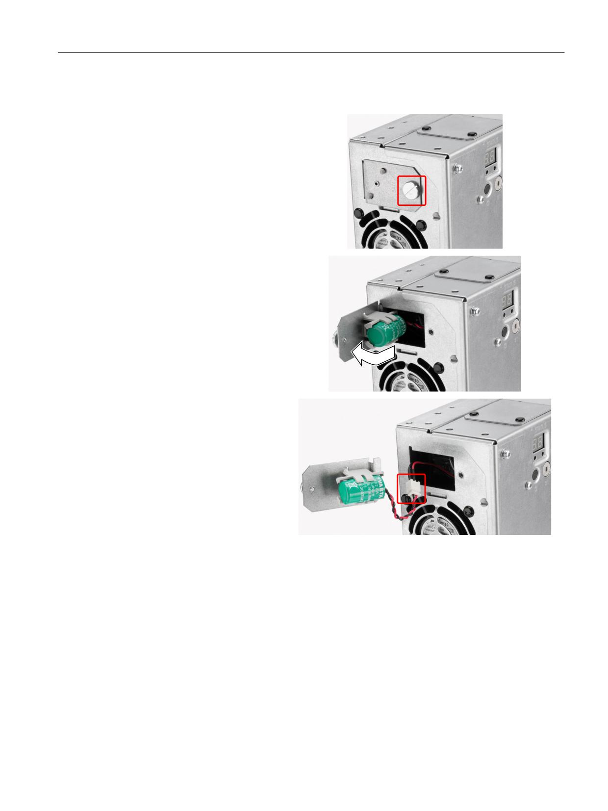
Replacing the battery
1. Open the battery compart-
ment.
2. Remove the battery holder.
3. Release the connecting ca-
ble.
4. Remove the old battery.
5. Fasten the new battery and reinsert the battery holder.
6. Close the battery compartment.
Reconfiguring the BIOS setup
If the battery replacement took longer than 30 seconds, the configuration data of the device
has been deleted and you need to reconfigure these in the BIOS Setup.
Operator panels
Manual, 03/2016, 6FC5397-1AP40-5BA3
273
PCU 50.5
15.10 Accessories
15.10
Accessories
15.10.1
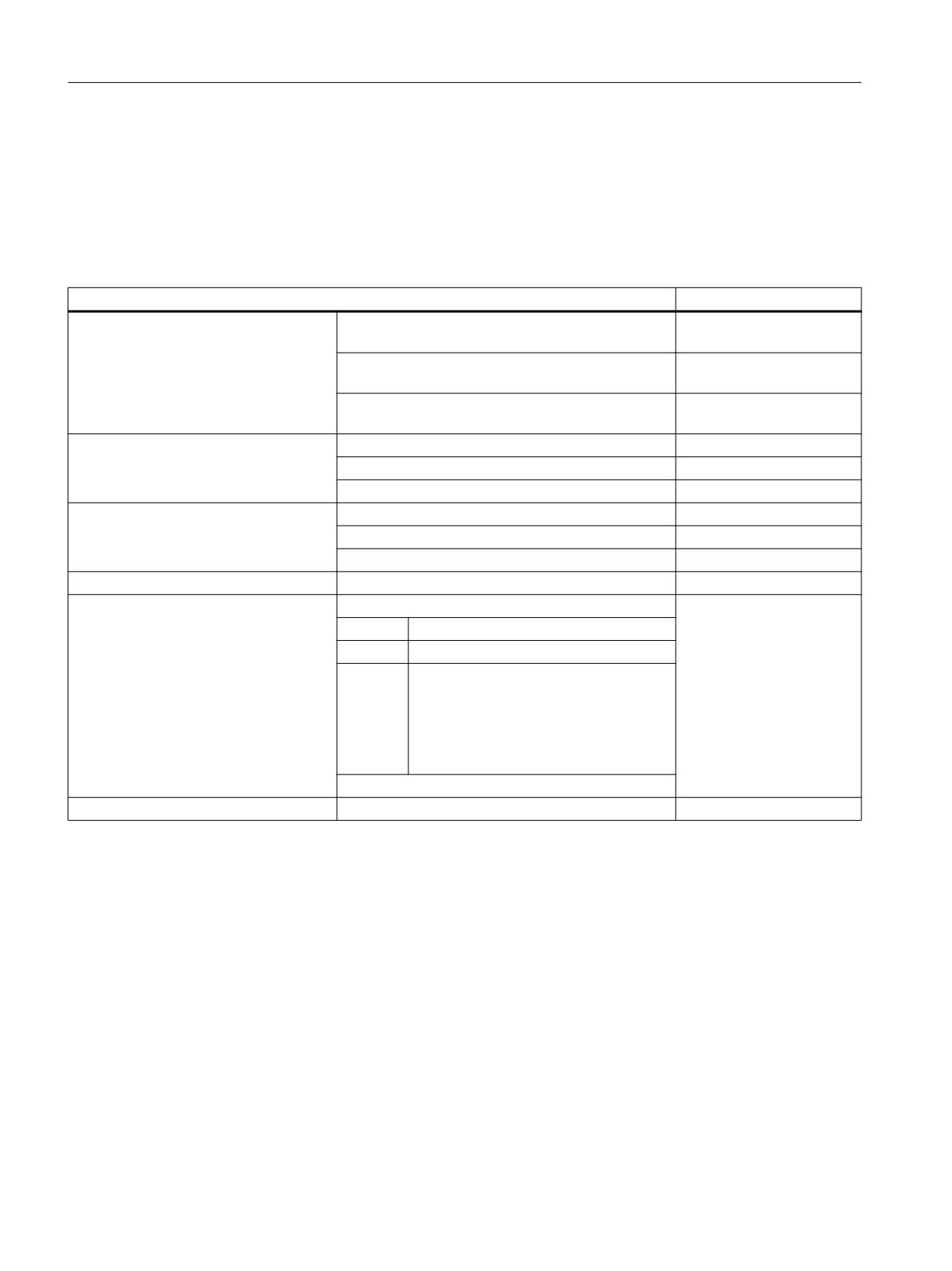
Overview
The following accessories are available for the PCU 50.5:
Component
Article number
Mounting bracket
Mounting bracket for PCU, video link receiver or
6FC5248-0AF20-2AA0
(1 set = 2 items)
TCU behind the operator panel front
Flat mounting bracket for PCU with or without video
6FC5248-0AF20-0AA0
link transmitter in the control cabinet
Book mounting bracket for PCU with or without vid-
6FC5248-0AF20-1AA1
eo link transmitter in the control cabinet
Memory expansion
1 GB DDR3 1066 MHz DIMM with ECC
6ES7648-2AJ40-1KA0
2 GB DDR3 1066 MHz DIMM with ECC
6ES7648-2AJ50-1KA0
4 GB DDR3 1066 MHz DIMM with ECC
6ES7648-2AJ60-1KA0
CompactFlash card
1 GB (empty)
6FC5313-5AG00-0AA1
2 GB (empty)
6FC5313-5AG00-0AA2
8 GB (empty)
6FC5313-6AG00-0AA0
USB FlashDrive
8 GB
6ES7648-0DC50-0AA0
SINUMERIK service pack
for PCU with Windows XP ProEmbSys on DVD
6FC5253-1CX10-1XU8
Recovery Media WIN XP ProEmbSys
Part 1:
Windows XP ProEmbSys incl. SP3
Part 2:
Ghost of basic software; emergency boot
Part 3 up
Multilingual user interface pack
to part 5:
(Chinese simplified, Chinese traditional,
Danish, German, Finnish, French, Ital-
ian, Japanese, Korean, Dutch, Polish,
Portuguese/Brazilian, Russian, Swed-
ish, Czech, Turkish, Hungarian)
Documentation (German/English)
PCI Multi I/O module
2 x COM, LPT
6ES7648-2CA01-0AA0
15.10.2
Installing and removing expansion modules
15.10.2.1
Memory expansion
Expansion options
On the motherboard there are two slots for memory modules (RAM banks).
Depending on what is inserted in the slots, you can expand the memory capacity of the PCU
from 1 GB up to 8 GB.
Operator panels
274
Manual, 03/2016, 6FC5397-1AP40-5BA3
PCU 50.5
15.10 Accessories
184-pin DDR3 memory modules can be used, unbuffered, with ECC; memory size 1, 2 or 4
GB.
Note
We urgently recommend to use memory modules approved by Siemens. No liability can be
accepted for restricted functionality when using memory modules from third-party suppliers.
Preparations
NOTICE
Damage to the module as result of missing EMC measures
The electrostatic components on the PCBs are highly sensitive to electrostatic discharge. It
is therefore vital to take precautionary measures when handling these components. Refer to
the directives for handling components that are sensitive to electrostatic charge.
1. Disconnect the device from the mains and withdraw all cables from the device.
2. Remove the covers from the service module and motherboard.
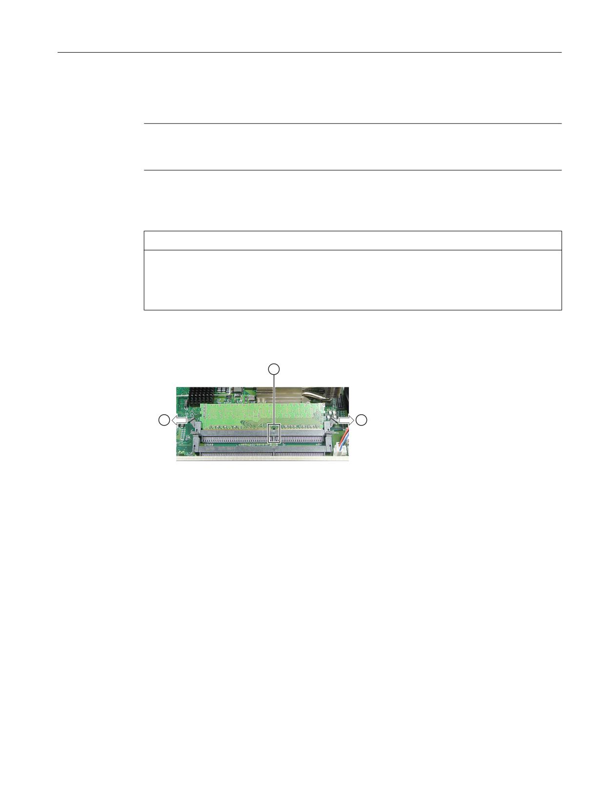
① Twist proof element
② Latches
Image 15-24 Inserted memory module
Installation of a memory module
1. Insert the module into the socket. When doing so, pay attention to the recess and/or twist
proof element ① on the connector side of the RAM module.
2. Press the module downwards, applying slight pressure, until the catches snap into place
②.
The PCU automatically detects the memory module that is installed. When switching on the
device, the split between "Base-Memory" and "Extended-Memory" is displayed.
Removal of the memory module
1. Release the latches ② at the left-hand and right-hand sides of the memory module.
2. Withdraw the memory module from the slot.
Operator panels
Manual, 03/2016, 6FC5397-1AP40-5BA3
275
PCU 50.5
15.10 Accessories
15.10.2.2
PCI cards
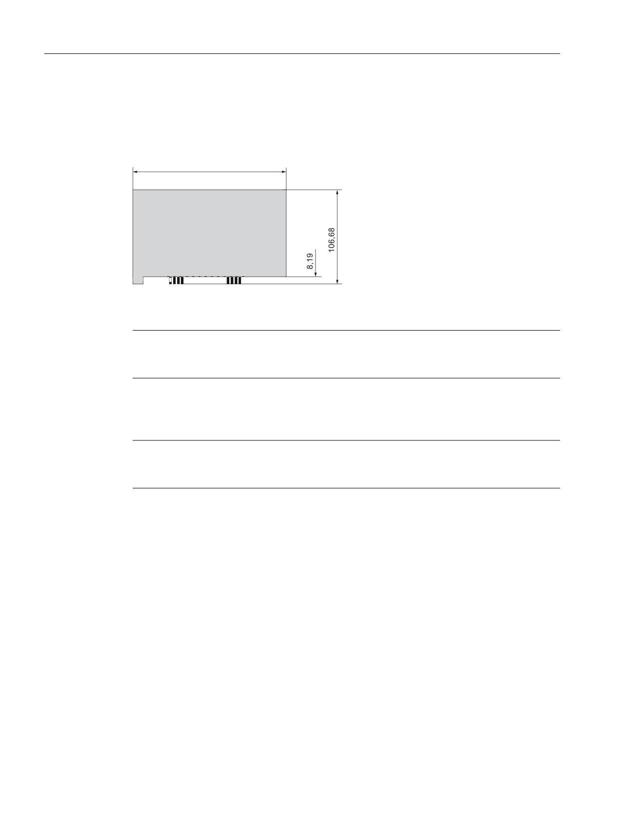
The PCU 50.5 is designed for use with a maximum of two modules conforming to PCI
specifications V 2.2. 5 V 32-bit PCI modules, universal (5 V & 3.3 V) 32-bit PCI modules and
PCI Express x16 modules can be used.
Image 15-25 Dimension drawing of a short PCI module
Note
The dimensions of the boards must not exceed the specified dimensions. Otherwise, contact
problems, malfunctions and installation difficulty cannot be ruled out.
Installing PCI cards
Note
When installing PCI cards, ensure that you do not touch or smudge the golden plug connections
of the card. This protects the card from malfunctioning.
Operator panels
276
Manual, 03/2016, 6FC5397-1AP40-5BA3
PCU 50.5
15.10 Accessories
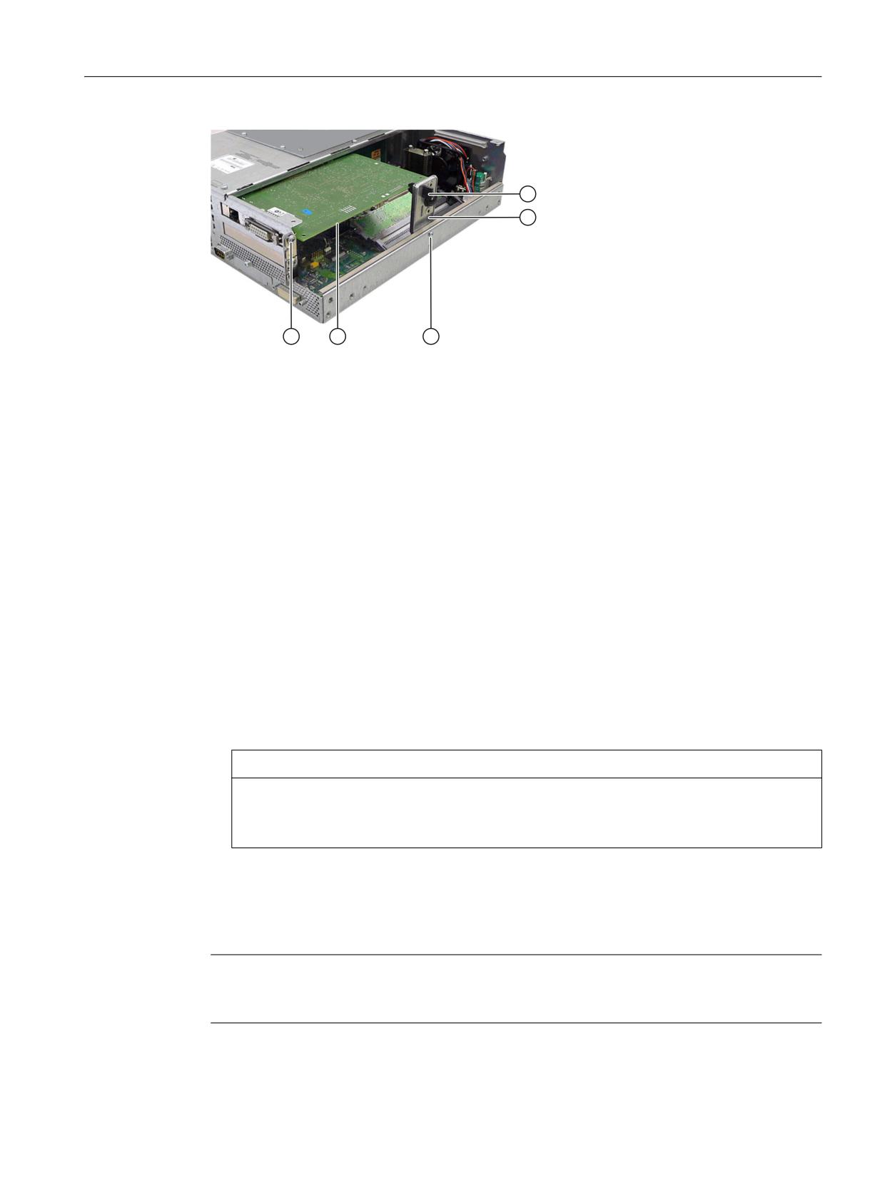
① Slider
② Module retainer
③ Retaining screw for the module retainer
④ Expansion module
⑤ Fixing screw for the slot sheet plate
Image 15-26 Expansion module inserted
Procedure
1. Disconnect the PCU from the line supply by withdrawing the line connector.
2. Remove the covers from the service module and motherboard.
3. Release the fixing screw ③ of the module retainer ② and remove the retaining bracket.
4. Release the retaining screws of the slot cover plate ⑤ for the corresponding upper or lower
slot and remove the slot plate.
5. Carefully but firmly insert the PCI card ④ into the appropriate slot.
6. Mount the module retainer ②.
7. Lock the PCI card ④ by inserting a slider ① through the guide slot until it securely holds
the edge of the module in its groove.
NOTICE
Damage to the module caused by squeezing the slider
No pressure should be applied to the module. Therefore, do not apply excessive force to
the slider when you push it onto the module.
8. Using a diagonal cutter, cut off the protruding part of the slider ①.
9. Mount the enclosure covers.
For half-height PCI cards, the following points do not apply: 7. and 8.
Note
If you use cards with a battery connection, connect the connecting cable to the battery before
you mount the enclosure covers (see Section: "Installing battery connecting cable").
Operator panels
Manual, 03/2016, 6FC5397-1AP40-5BA3
277
PCU 50.5
15.10 Accessories
PCI multi I/O module
If you use the PCI multi I/O module, install the driver from the driver CD provided according to
the instructions. The BIOS setup must be modified in order that the card functions error-free.
In the menu, set:
Advanced → I/O Device Configuration → Internal COM 1: Disabled
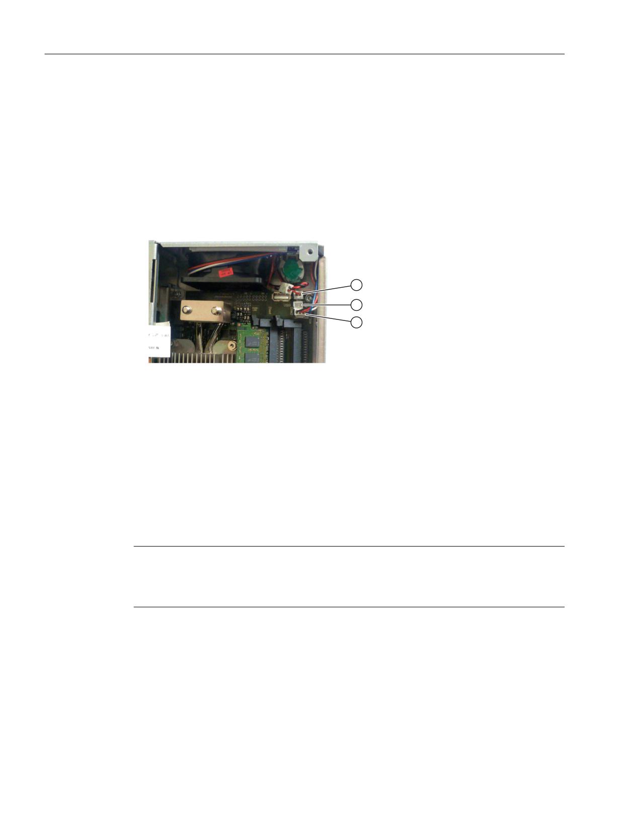
Installing the battery connecting cable
● Only for MC-specific PCI cards.
● Connect the PCI module via the connecting cable to the battery connection ②.
① Plug for connecting the backup battery
② Connector plug for connecting the PCI module to the battery
③ Plug for connecting the device fan
Image 15-27 Installing the battery connecting cable for PCI modules
15.10.2.3
CompactFlash card
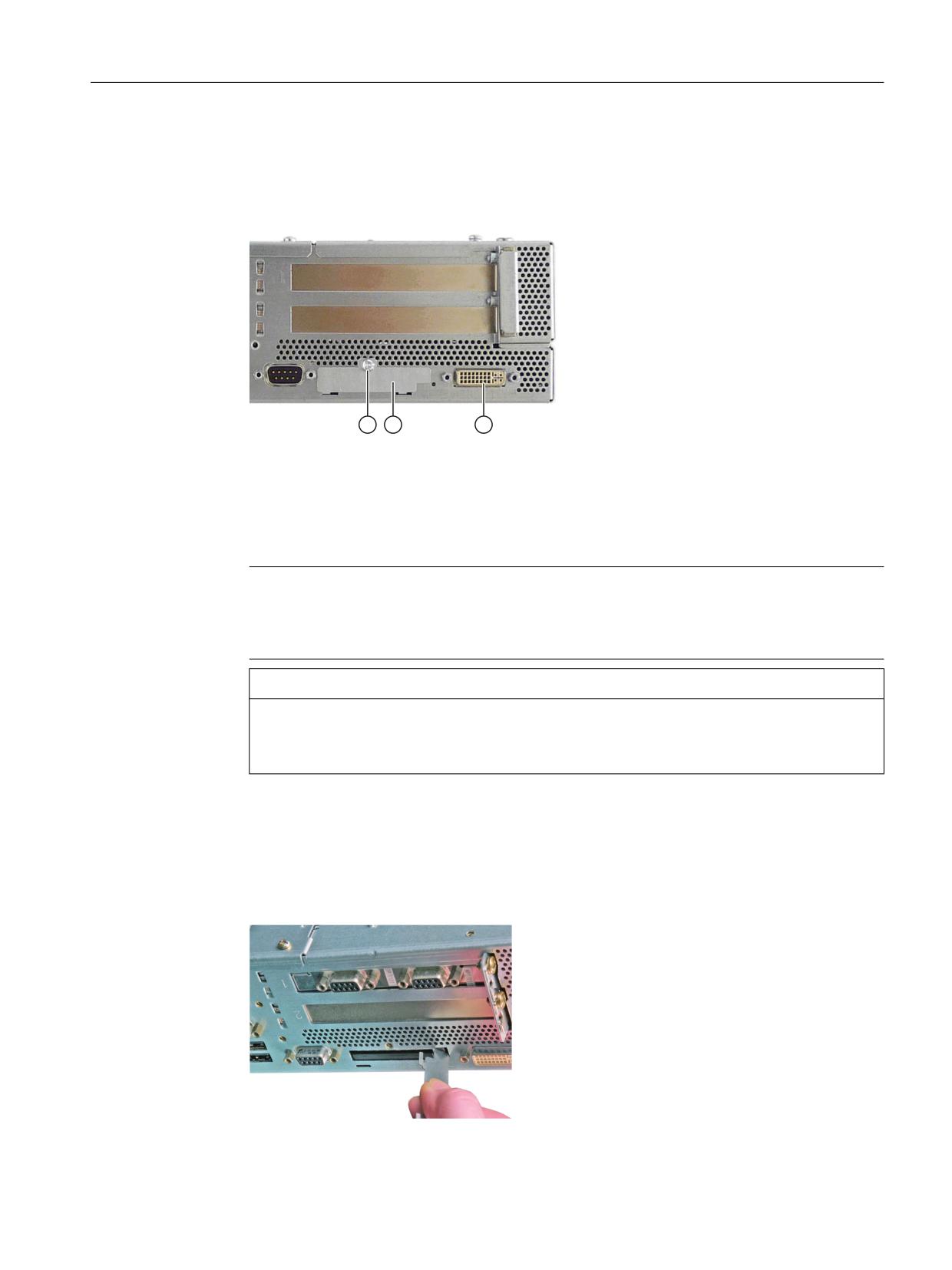
The PCU 50.5 provides a protected slot for CompactFlash cards (types I/II). The slot is located
behind the cover plate ②.
We recommend using CompactFlash cards from Siemens for industrial applications because
they offer special data security, service life and data transfer speeds.
Note
The slot for the CompactFlash card is not suitable for hot-plugging. You should therefore insert
the CompactFlash card before you switch on the PCU and only remove the card after you have
switched off the PCU.
Installing the CompactFlash card behind the cover plate
1. Separate the PCU from the power supply by disconnecting the main power connector.
2. Release the fixing screw ③ for the cover plate ② of the slot.
3. Fold up the cover plate ② and slide it towards the DVI-I interface ①. Lift the cover plate
slightly until it releases on the left-hand side. Then slide it back until it releases on the right-
hand side.
Operator panels
278
Manual, 03/2016, 6FC5397-1AP40-5BA3
PCU 50.5
15.10 Accessories
4. Carefully slide the CompactFlash card straight into the card slot until it snaps in. Hold the
CompactFlash card so that its label side faces toward the front panel of the PC.
5. Close the card slot by inserting the cover plate ② (lock it on the left and right) and screw
in the fixing screw ③.
① DVI-I interface
② Cover plate of the CompactFlash card slot
③ Retaining screw for cover plate
Image 15-28 Installing the CompactFlash card behind the cover plate
Note
The slot for the CompactFlash card is coded against incorrect insertion of the card. If it is
incorrectly inserted, then approx. 1 cm protrudes out of the enclosure and it does not
function.
NOTICE
Damage to the CompactFlash card caused by forced insertion
If the CompactFlash card is difficult to insert, then turn the card over. Never insert the
CompactFlash card with force.
Removing the CompactFlash card behind the cover plate
1. Open the card slot as described under "Installing the CompactFlash card ..." (points 1-3).
2. Press the eject button on the right-hand side of the module slot (e.g. using the narrow end
of the cover plate).
Operator panels
Manual, 03/2016, 6FC5397-1AP40-5BA3
279
PCU 50.5
15.10 Accessories
3. Remove the CompactFlash card.
4. Close the card slot.
Operator panels
280
Manual, 03/2016, 6FC5397-1AP40-5BA3
TCU x0.2
16
16.1
Description
16.1.1
Overview
A Thin Client Unit (TCU) allows the spatial separation between an OP/TP operator panel front
and the PCU/NCU. For this reason, the user interface is copied to one/several operator panel
fronts, each with a TCU.
Validity
The description applies to the following TCU:
Designation
Article number
Thin Client Unit 20.2
6FC5312-0DA00-0AA2
Thin Client Unit 30.2
6FC5312-0DA00-1AA0
Features
● Design of flat operator panels through the shallow installation depth and low power loss.
● Graphic: Resolution for 16-bit color depth:
- TCU 20.2: 640 x 480 to 1024 x 768 pixels
- TCU 30.2: 640 x 480 to 1280 x 1024 pixels
● Low-vibration installation of the PCU in the control cabinet
● Effective operation of larger machines.
● Signal transmission between PCU/NCU and operator panel via Industrial Ethernet
The distance of the components is determined by the maximum distance between two
network nodes / access points (100 m).
● The same operator control screen is displayed simultaneously on all operator panel fronts;
it can also be operated from all operator panel fronts.
● The operation on an operator panel front connected via TCU has the same access rights
as the operation on an operator panel front connected directly to the PCU.
● The mixed operation of operator panel fronts connected via TCU and an operator panel
front connected directly to the PCU is possible.
● TCU x0.2 is compatible with previous models, which means that mixed operation is possible.
Operator panels
Manual, 03/2016, 6FC5397-1AP40-5BA3
281
TCU x0.2
16.1 Description
Preconditions
● NCU 7x0
● Operator panel fronts:
- TCU 20.2: OP 010 / OP 010C / OP 010S / OP 012 / OP 015 / OP 015A / TP 015A
- TCU 30.2: OP 019
Design
The TCUs are coupled via Ethernet as Thin Clients in a dedicated subnetwork (via DHCP
server on the PCU/NCU) to the PCU/NCU.
Interfaces:
● To connect the mouse, keyboard and USB flash drive
- TCU 20.2: 3 x USB 2.0 Hi-Speed
- TCU 30.2: 5 x USB 2.0 Hi-Speed
● Ethernet 10/100/1000 Mbit/s
The speed in Ethernet system networks automatically sets itself to the maximum possible
value. 1000 Mbit/s can only be achieved with NCU 7x0.3 PN and PCU 50.5 (if a PCU is
required).
Note
The Ethernet interfaces have what is called autocrossing functionality, i.e. when required,
send and receive lines switch over. If, however, the partner does not permit "Autocrossing",
a crossover cable is required.
16.1.2
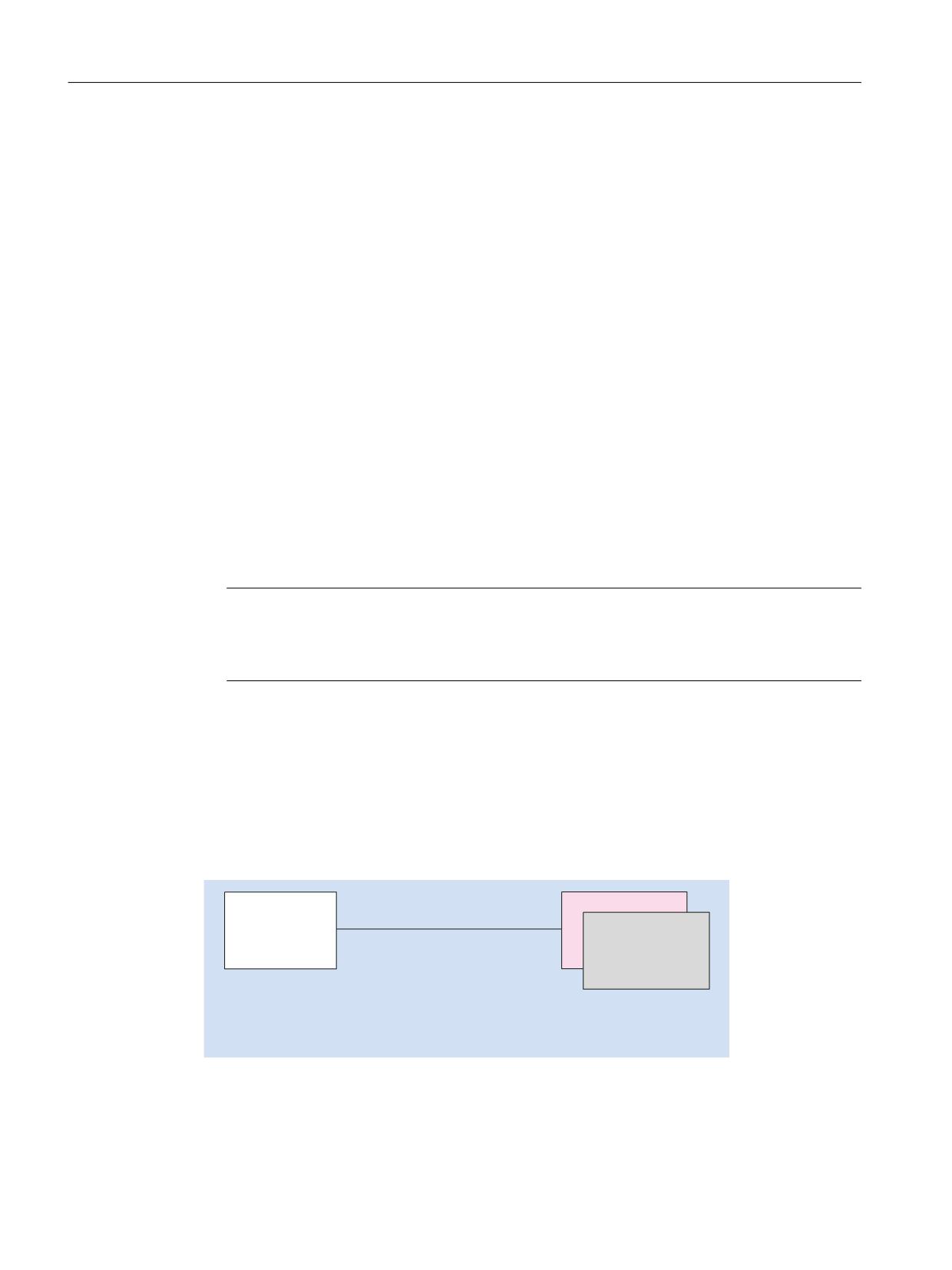
Configurations
Configurations
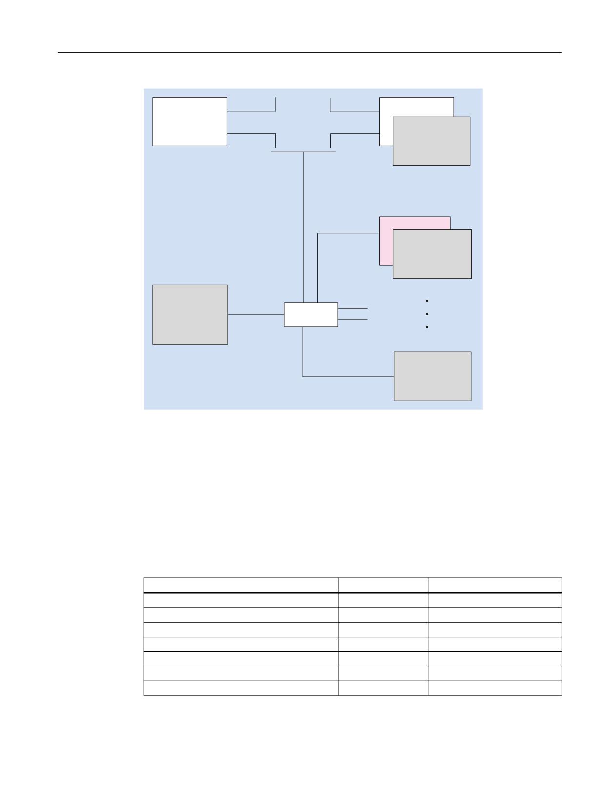
The following configurations of the distributed structure are possible with a TCU x0.2:
1&8
7&8 [
2SHUDWRU SDQHO IURQW
,QGXVWULDO (WKHUQHW
0RXQWLQJ EUDFNHW UHTXLUHG
IRU 7&8 [
)&
$)
$$ RPLWWHG IRU 23
6
$GGLWLRQDO 7&8 [
IRU RSHUDWRU SDQHO IURQWV ZLWK LQWHJUDWHG 7&8 QRW QHFHVVDU\
Image 16-1 Minimum configuration with an operator panel front
Operator panels
282
Manual, 03/2016, 6FC5397-1AP40-5BA3
TCU x0.2
16.2 Interfaces
7&8 [
3&8
3&8
,QGXVWULDO (WKHUQHW
2SHUDWRU SDQHO IURQW
0RXQWLQJ EUDFNHW UHTXLUHG
IRU PRXQWLQJ LQ WKH FRQWURO FDELQHW
3&8b
)&
$)
$$ RU
)&
$)
$$
,QGXVWULDO
(WKHUQHW
7&8 [
IRU PRXQWLQJ RQ RSHUDWRU SDQHO IURQW
7&8 [
3&8
2SHUDWRU SDQHO IURQW
)&
$)
$$
QRW IRU 23
6
1&8 [
31
,QGXVWULDO
(WKHUQHW
6ZLWFK
,QGXVWULDO
2SHUDWRU SDQHO IURQW
(WKHUQHW
ZLWK LQWHJUDWHG
7&8
Image 16-2 Maximum configuration, several TCUs connected to an NCU 7x0
Information about TCU commissioning can be found in "General information and networking",
Chapter: "Networking".
16.2
Interfaces
Overview
Function
Designation
Description
Double USB interface 1 1)
X203 / X204
2 x USB 2.0 Hi-Speed type A
Double USB interface 2 1)
X212 2) / X213
2 x USB 2.0 Hi-Speed type A
Interface for direct keys
X205
2 x 10-pin plug connector
24 VDC power supply
X206
3-pin terminal block
I/O USB interface K1 3) 4)
X207
2 x 13-pin plug connector
LVDS display interface K2 3) 4)
X208
2 x 10-pin plug connector
LVDS display interface K3 4)
X209 2)
2 x 10-pin plug connector
Operator panels
Manual, 03/2016, 6FC5397-1AP40-5BA3
283
TCU x0.2
16.2 Interfaces
Function
Designation
Description
Ethernet interface
X202
8-pin RJ45 socket
USB interface
X211 2)
USB 2.0 Hi-Speed type A
1)
One of the interfaces can be loaded with 500 mA, the other with 100 mA.
2)
Only TCU 30.2
3)
To connect to an operator panel front 10" up to 15"
4)
To connect to an operator panel front OP 019
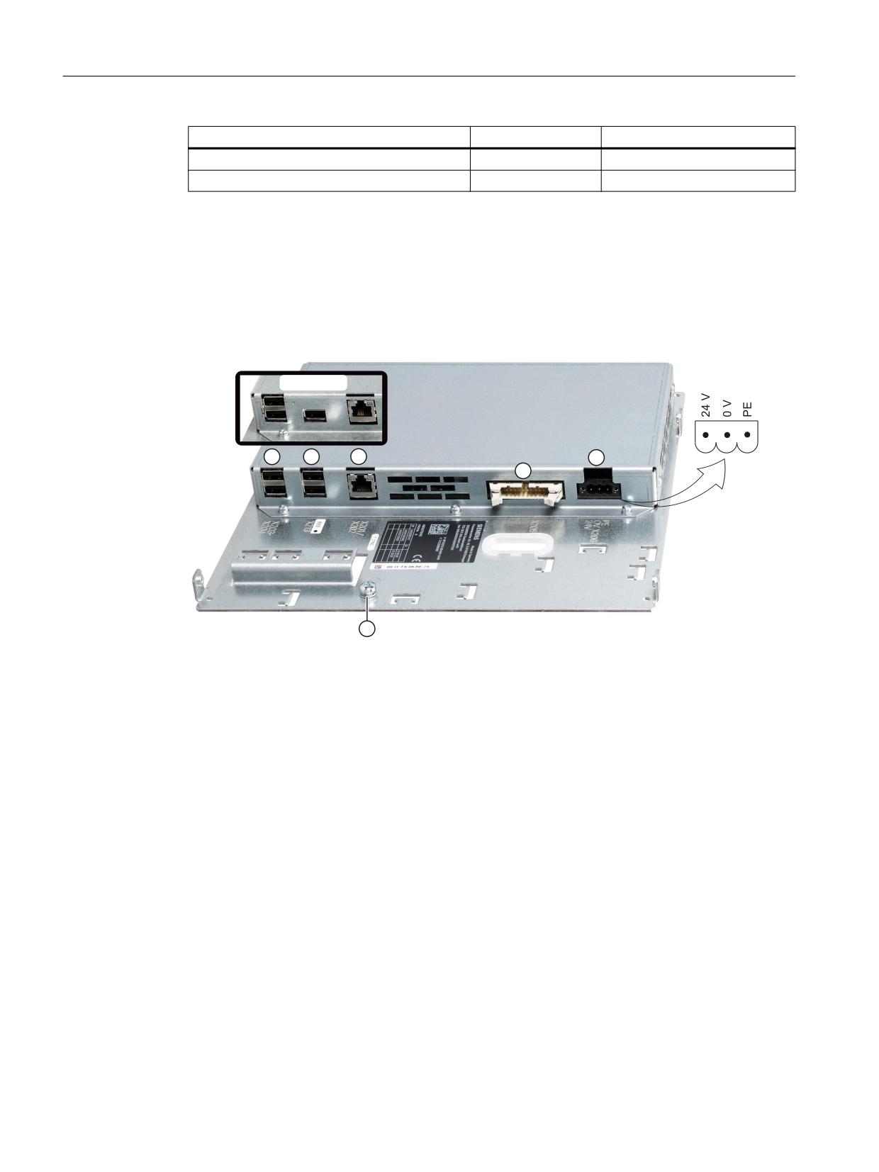
View
7&8
① X203 /
USB interfaces
X204
② X212/X213 USB interfaces (for TCU 20.2, there is no X212)
③ X202
Ethernet interface
④ -
Grounding screw
⑤ X205
Interface for direct keys
⑥ X206
24 VDC power supply
Image 16-3 Front view of the TCU 30.2 with interfaces
Operator panels
284
Manual, 03/2016, 6FC5397-1AP40-5BA3
TCU x0.2
16.3 Mounting the TCU on the operator panel front
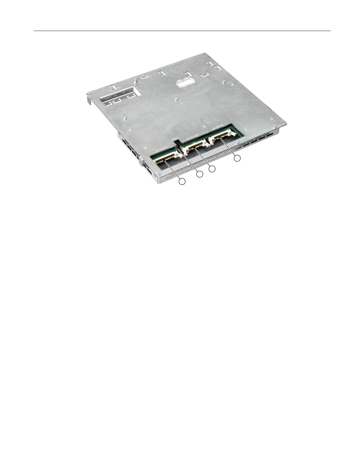
① X209
LVDS display interface K3 (not for TCU 20.2)
② X208
LVDS display interface K2
③ X211
USB interface (not for TCU 20.2)
④ X207
I/O USB interface K1
Image 16-4 Rear view of the TCU 30.2 with interfaces
Pin assignment
The pin assignment of the interfaces, see "General information and networking" →
"Connecting".
16.3
Mounting the TCU on the operator panel front
Before assembling the two components, the interface cables of the operator panel front (IO/
USB cable K1, K2 display cable and, if necessary, K3) must be inserted into the corresponding
socket of the TCU (visible behind the housing cut-out).
Operator panels
Manual, 03/2016, 6FC5397-1AP40-5BA3
285
TCU x0.2
16.3 Mounting the TCU on the operator panel front
OP 010S
The operator panel front OP 010S and the TCU are screwed together without additional
mounting brackets.
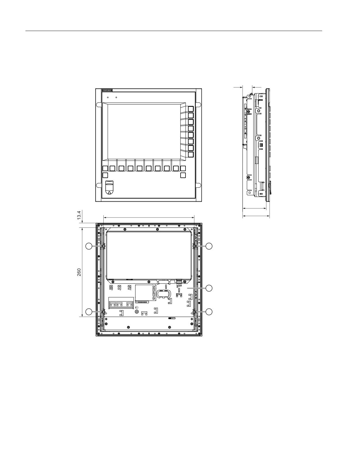
23
6
7&8
①
4 x M3 screws to fasten the TCU support plate to the OP 010S
② TCU support plate
Image 16-5 Mounted TCU with OP 010S, front, side and rear view
Operator panels
286
Manual, 03/2016, 6FC5397-1AP40-5BA3
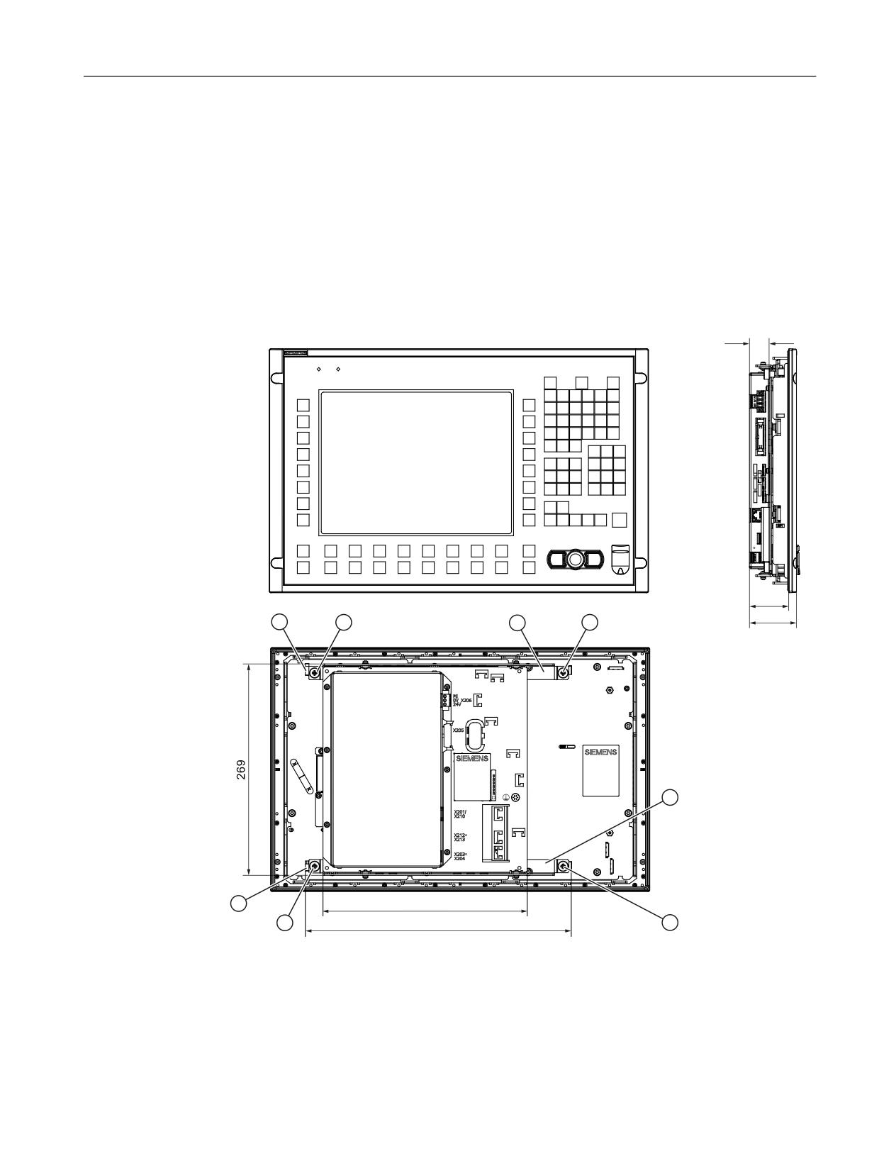
TCU x0.2
16.3 Mounting the TCU on the operator panel front
OP 010, OP 010C, OP 012, OP 015, OP 015A, TP 015A
Two mounting brackets (must be ordered separately) are required for mounting these operator
panel fronts (see Section: "Accessories").
1. Screw the mounting bracket ③ onto the TCU.
2. Use the two hinge catches ① to suspend the TCU mounting bracket unit (like a PCU) in
the operator panel front.
3. Insert cables K1 and K2.
4. Close the cabled TCU mounting bracket unit and attach it using the four knurled screws
②.
①
2 x hinge catches
②
4 x knurled screws for attaching the mounting brackets to the operator panel front
③
2 x mounting brackets
Image 16-6 Mounted TCU (example with OP 012) in front, side and rear view
Operator panels
Manual, 03/2016, 6FC5397-1AP40-5BA3
287
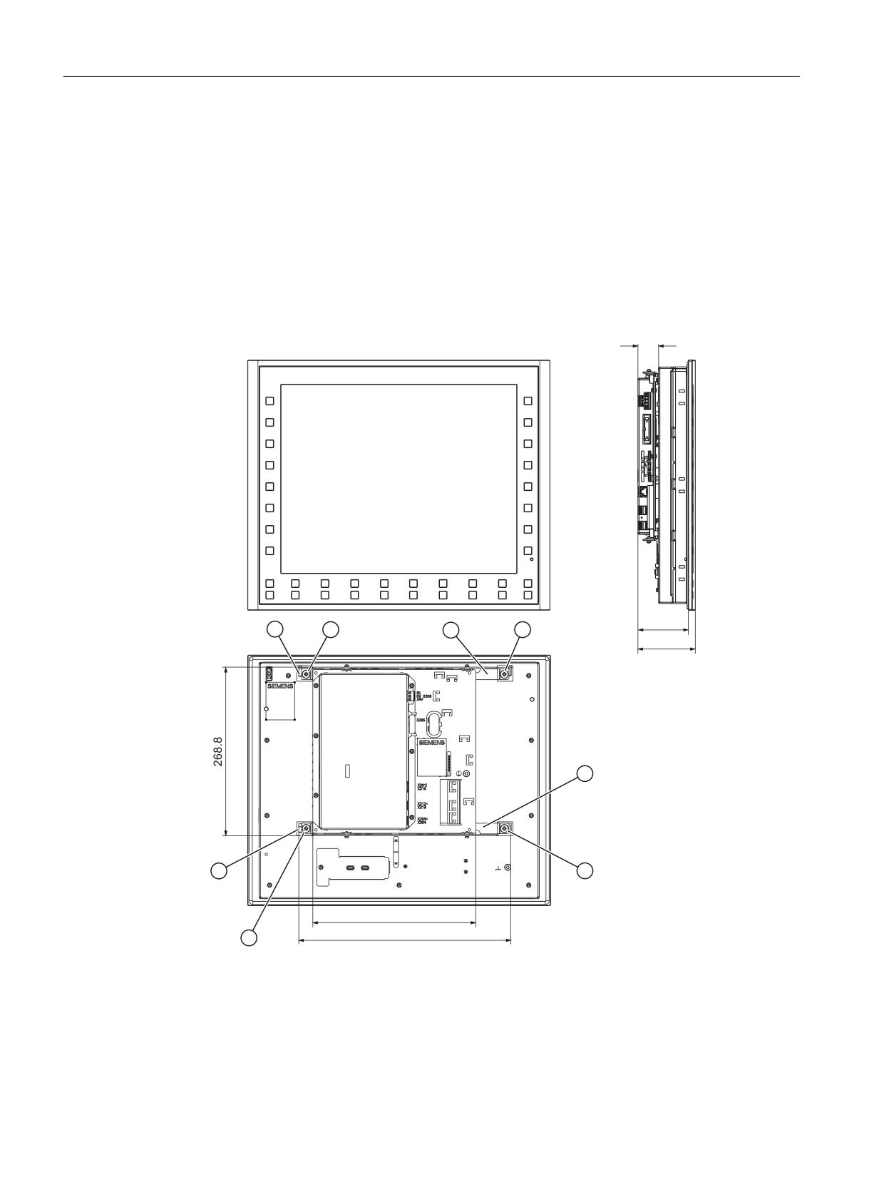
TCU x0.2
16.3 Mounting the TCU on the operator panel front
OP 019
Two mounting brackets (must be ordered separately) are required for mounting this operator
panel front (see Section: "Accessories").
1. Screw the mounting bracket ③ onto the TCU.
2. Use the two hinge catches ① to suspend the TCU mounting bracket unit (like a PCU) in
the operator panel front.
3. Insert cables K1, K2 and K3.
4. Close the cabled TCU mounting bracket unit and attach it using the four knurled screws
②.
23
7&8
①
2 x hinge catches
②
4 x knurled screws for attaching the mounting brackets to the operator panel front
③
2 x mounting brackets
Image 16-7 Mounted TCU 30.2 with OP 019, front, side and rear views
Operator panels
288
Manual, 03/2016, 6FC5397-1AP40-5BA3
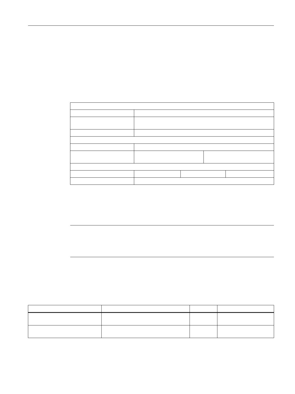
TCU x0.2
16.5 Accessories
Tensile strain relief
Since some of the interfaces do not have a cable strain relief for the cables to be connected,
it is recommended to secure the cables to the u-shaped lugs on the supporting plate using
cable ties.
16.4
Technical data
Safety
Safety class
III; PELV according to EN 50178
Degree of protection accord-
IP20 (mounted)
ing to DIN 40050
Approvals
CE / cULus
Electrical data
Power supply 1)
24 VDC (20.4 V ... 28.8 V)
Power consumption, max.
TCU 20.2:
TCU 30.2:
9 W 2) / 40 W 3)
10 W 2) / 60 W 4)
Mechanical data (without packing)
Dimensions
Width: 260 mm
Height: 265 mm
Depth: 34 mm
Weight
1.96 kg
1)
The power supply must be provided as protective extra low-voltage with safe isolation (according to
EN 60204-1, PELV).
2)
Only TCU
3)
TCU with OP 015 and 2 x 0.5 A at USB
4)
TCU with OP 019 and 2 x 0.5 A / 4 x 0.1 A at USB
Note
Information about the climatic and mechanical environmental conditions is contained in the
associated section under:
"General notes and interconnection" → "Operational planning".
16.5
Accessories
Table 16-1
Accessories for TCU
Components
Description
Quantity
Article number
Mounting bracket
Mounting bracket for PCU, video link re-
1 set
6FC5248-0AF20-2AA0
ceiver or TCU behind operator panel front
(2 items)
Direct key cable
Ribbon cable for connection of the direct
1
6FC5347-0AF10-0AA0
key interfaces for OP and TCU.
Operator panels
Manual, 03/2016, 6FC5397-1AP40-5BA3
289

TCU x0.2
16.5 Accessories
Components
Description
Quantity
Article number
Industrial
IE FC Standard Ca-
4-core, shielded TP installation cable for
1
6XV1840-2AH10
Ethernet ca-
ble GP 2 x 2 (Type A)
connection to IE FC Outlet RJ45/
ble
IE FC RJ45 Plug; PROFINET-compatible;
with UL approval;
sold by the meter (max. 1000 m; min. 20 m);
IE FC Trailing Cable
4-core, shielded TP installation cable for
1
6XV1840-3AH10
GP 2 x 2 (Type C)
connection to IE FC Outlet RJ45/
IE FC RJ45 Plug 180/90 for use in trailing
cables; PROFINET-compatible; without UL
approval;
sold by the meter (max. 1000 m; min. 20 m);
Plug-in con-
IE FC RJ45 Plug 180
RJ plug connector for Industrial Ethernet
1
6GK1901-1BB10-2AA0
nector
with robust metal housing and integrated
cutting/clamping contacts; with 180° outgo-
ing cable
Operator panels
290
Manual, 03/2016, 6FC5397-1AP40-5BA3
Index
OP 015AT, 119
TP 015AT, 156
B
DKM cable
Direct key module, 206
Backlight inverter
OP 015, 86, 87
OP 015A, 102
E
OP 015AT, 119
TP 015A, 137
Error messages
TP 015AT, 156
Booting, 257
Battery replacement, 272
Ethernet cable
BIOS
Thin Client Unit, 290
BIOS post code, 261
Ethernet strain relief, 240
BIOS setup
Ethernet, industrial
PCU 50.5, 245, 248
Thin Client Unit, 281
Boot sequence
Error messages, 257
Booting
F
Error messages, 257
FB9 Proxy, 252
fb9_proxy.ini, 253
Film labels
C
OP 010, 39
Coding switches
OP 012, 75
Direct key module, 203
Front USB interface
CompactFlash card
OP 010, 27, 28
PCU 50.5, 278
OP 010C, 52
Configurations
OP 010S, 43, 44
TCU 30.2, 282
OP 012, 61, 62
OP 015, 79, 80
OP 015A, 91
D
TP 015A, 127
DB19, 252
DHCP server
G
Thin Client Unit, 282
Direct key module
Gestures
Coding switches, 203
Displaying the TCU menu, 166, 193
Dimensions, 211
DKM cable, 206
LEDs, 204
H
Power consumption, 211
Hard disk drive
PROFIBUS cable, 205
PCU 50.5, 213
PROFIBUS DP, 203
Display
OP 010, 39
I
Display support
OP 010, 40
Individual parts
OP 012, 76
OP 010, 36
OP 015, 86, 87
OP 010C, 60
OP 015A, 103
OP 012, 73
Operator panels
Manual, 03/2016, 6FC5397-1AP40-5BA3
291
Index
OP 015, 86
Mounting
OP 015A, 102
Mounting opening, 170
OP 015AT, 119
One person installation, 171
TP 015A, 136
Mounting bracket
TP 015AT, 156
OP 012, 69
Installation
OP 015A, 97
Mounting opening, 197
Thin Client Unit, 287, 288, 289
One person installation, 198
Interfaces, 168, 195
O
On/off switch
K
PCU 50.5, 216
Key symbols
OP 010
OP 010, 29
Dimension sheet, 33
OP 010C, 53
Dimensions, 36
OP 010S, 45, 81
Front USB interface, 27, 28
OP 012, 63, 130
Individual parts, 36
OP 015, 45, 81
Installation, 33
OP 019, 180
Installation opening, 33
OP 08T, 13
Key symbols, 29
TP 015A, 63, 130
Keypads, 29
Keyboard, 167
Mounting opening, 46, 57
Keyboard controller
Power consumption, 36
OP 010, 39
Slide-in labels, 37
OP 012, 76
TFT flat screen, 27
OP 015, 86, 87
Tightening torques, 36
OP 015A, 102
VGA resolution, 27
OP 015AT, 119
OP 010C
TP 015A, 137, 139
Dimension drawings, 57
TP 015AT, 156, 158
Dimensions, 59
Front USB interface, 52
Individual parts, 60
L
Key symbols, 53
Keypads, 53
LCD unit
Power consumption, 59
OP 012, 76
TFT flat screen, 51
OP 015, 86
Tightening torques, 59
OP 015A, 103
VGA resolution, 51
OP 015AT, 119
OP 010S
TP 015A, 137
Dimension drawings, 46
TP 015AT, 156
Dimensions, 50
LEDs
Front USB interface, 43, 44
Direct key module, 204
Key symbols, 45, 81
PCU 50.5, 217
Power consumption, 50
Lithium battery, 272
TFT flat screen, 43
Tightening torques, 50
VGA resolution, 43
M
OP 012
Membrane connector
Dimension sheet, 67
OP 012, 76
Dimensions, 73
Memory expansion
Front USB interface, 61, 62
PCU 50.5, 274
Individual parts, 73
Operator panels
292
Manual, 03/2016, 6FC5397-1AP40-5BA3
Index
Installation opening, 66
Article number, 191
Key symbols, 63, 130
Characteristics, 191
Keypads, 63, 129
Spare parts, 202
Mounting bracket, 69
OP 08T
Power consumption, 73
Dimensions, 18
SVGA resolution, 61
Power consumption, 18
TFT flat screen, 61
Tightening torques, 18
Tightening torques, 73
Operation
OP 015
Gloves, 166, 194
Dimension drawings, 82, 185
Keylock, 166
Dimensions, 85
Front USB interface, 79, 80
Individual parts, 86
P
Key symbols, 45, 81
PCI card
Mounting opening, 82
PCU 50.5, 277
Power consumption, 85
PCI hardware interrupt, 230
TFT flat screen, 79
PCI multi I/O module, 278
Tightening torques, 85
PCU 50.5
OP 015 black
BIOS setup, 245, 248
Accessories, 175
CompactFlash card, 278
Features, 163
Dimension drawings for mounting, 232
Order number, 163
Dimensions, 263
Spare parts, 175
Hard disk drive, 213
OP 015A
Insert the battery connecting cable, 278
Dimensions, 101
LEDs, 217
Front USB interface, 91
Memory expansion, 274
Individual parts, 102
Mounting bracket, 231, 274
Mounting bracket, 97
Mounting positions, 240
Mounting opening, 96
On/off switch, 216
Power consumption, 101
PCI card, 277
TFT flat screen, 91
Power consumption, 263
Tightening torques, 101
Screen resolution, 214
OP 015AT
Touch software, 249
Article number, 111
USB FlashDrive, 246
Dimension sheet, 117
Work memory, 213
Dimensions, 118
PLC alarms, 255
Individual parts, 119
Power supply
Power consumption, 118
PCU 50.5, 268
TFT flat screen, 111
PROFIBUS cable
Tightening torques, 118
Direct key module, 205
OP 019
PROFIBUS DP
Article number, 177
Direct key module, 203
Dimensions, 189
Key symbols, 180
LED displays, 181
R
Mounting opening, 185
Power consumption, 189
Replacement intervals, 265
TFT flat screen, 177
Replacing
Tightening torques, 189
Battery, 272
View, 179
OP 019 black
Accessories, 202
Operator panels
Manual, 03/2016, 6FC5397-1AP40-5BA3
293
Index
Individual parts, 136
Key symbols, 63, 130
S
Keypads, 63, 129
Mounting opening, 132
Screen calibration
Power consumption, 135
TP 015A, 134
Tightening torques, 136
TP 015AT, 154, 174
Touch screen, 127
Screen resolution
XGA resolution, 127
PCU 50.5, 214
TP 015AT
Slide-in labels
Dimension sheet, 154
OP 010, 37
Dimensions, 155
OP 012, 74
Individual parts, 156
OP 015A, 103
Power consumption, 155
OP 015AT, 119
TFT flat screen, 147
TP 015A, 137
Tightening torques, 155
TP 015AT, 156
SVGA resolution
OP 012, 61
U
USB FlashDrive
T
PCU 50.5, 246
TCU 30.2
Configurations, 282
V
Technical specifications
Dimensions, 174, 202
VGA resolution
Power consumption, 174, 202
OP 010, 27
Tightening torques, 174, 202
OP 010C, 51
TFT flat screen
OP 010S, 43
OP 010, 27
View, 165, 193
OP 010C, 51
OP 010S, 43
OP 012, 61
W
OP 015, 79
Work memory
OP 015A, 91
PCU 50.5, 213
OP 015AT, 111
TP 015AT, 147
Thin Client Unit
X
DHCP server, 282
Dimensions, 289
XGA resolution
Ethernet cable, 290
TP 015A, 127
Ethernet, industrial, 281
Mounting bracket, 287, 288, 289
Touch controller
TP 015A, 139
TP 015AT, 158
Touch screen
TP 015A, 127
Touch software
PCU 50.5, 249
TP 015A
Dimensions, 136
Front USB interface, 127
Operator panels
294
Manual, 03/2016, 6FC5397-1AP40-5BA3

1
Handheld Terminal HT 2
Handheld Terminal HT 8
2
3
Mini-handheld unit
SINUMERIK
Electronic handheld
4
handwheel
SINUMERIK 840D sl
Handheld units
Handwheel connection
5
module
Manual
Valid for: SINUMERIK 840D sl / 840DE sl control
03/2016
6FC5397-1AP40-5BA3
Table of contents
1
Handheld Terminal HT 2
7
1.1
Description
7
1.2
Operator control and display elements
9
1.2.1
Overview
9
1.2.2
Description
10
1.3
Connecting
14
1.3.1
Overview
14
1.3.2
Terminal Box PN
15
1.3.2.1
Description
15
1.3.2.2
PN Plus terminal box
17
1.3.2.3
Interface assignment on the PN Plus terminal box
18
1.3.2.4
PN Basic terminal box
25
1.3.3
Connection module Basic PN
27
1.3.3.1
Features
27
1.3.3.2
interfaces
27
1.3.3.3
Dimension drawing
31
1.3.3.4
Installing the terminating connector
32
1.3.4
Connection examples of enabling button and emergency stop button
34
1.3.5
Connecting cable
38
1.3.6
Power Supply
41
1.3.7
Unplugging/plugging during operation
41
1.4
Commissioning
42
1.4.1
BIOS
42
1.4.1.1
BIOS powering up
42
1.4.1.2
Settings in the BIOS menu
42
1.4.1.3
Error handling
44
1.4.2
Interface signals
45
1.4.3
Application example for HT8 and HT 2 involving mixed operation
52
1.4.4
Application example for two HT 2 units connected to SINUMERIK
54
1.5
Dimension drawing
55
1.6
Maintenance and Service
55
1.7
Technical data
56
1.7.1
Handheld Terminal HT 2
56
1.7.2
Connection module Basic PN
59
1.7.3
PN terminal box
60
1.8
Spare parts
61
1.9
Accessories
61
1.9.1
Overview
61
1.9.2
Mount
62
1.9.3
Retaining magnet
63
1.9.4
Slide-in label
66
1.9.4.1
Labeling the slide-in labels
66
Handheld units
Manual, 03/2016, 6FC5397-1AP40-5BA3
3
Table of contents
1.9.4.2
Replacing the slide-in labels
70
2
Handheld Terminal HT 8
73
2.1
Description
73
2.2
Operator controls and indicators
75
2.2.1
View
75
2.2.2
Description
77
2.2.3
Screen brightness control
80
2.3
interfaces
81
2.3.1
Overview
81
2.3.2
Description
81
2.4
Connecting
83
2.4.1
Overview
83
2.4.2
Terminal Box PN
85
2.4.2.1
Description
85
2.4.2.2
PN Plus terminal box
86
2.4.2.3
PN Basic terminal box
87
2.4.2.4
Interfaces
88
2.4.3
Connecting module Basic PN
89
2.4.3.1
Description
89
2.4.3.2
interfaces
89
2.4.3.3
Dimension drawing
93
2.4.3.4
Installing the terminating connector
94
2.4.4
Connecting cable
95
2.4.5
Power Supply
97
2.4.6
Unplugging/plugging during operation
98
2.5
Commissioning
98
2.5.1
SINUMERIK Operate
98
2.5.1.1
Activating/deactivating the virtual keyboard
98
2.5.1.2
Configuring the traversing keys
99
2.5.1.3
Configuring user-specific key labeling
104
2.5.1.4
Configuring the function display at user-specific keys (U keys)
106
2.5.1.5
Troubleshooting
108
2.5.2
HMI Advanced
108
2.5.2.1
Configuring the traversing keys of the HT 8
108
2.5.2.2
Configuring user-specific key labeling
110
2.6
Maintenance and Service
112
2.7
Technical data
113
2.7.1
Handheld Terminal HT 8
113
2.7.2
Connection module Basic PN
115
2.7.3
PN terminal box
115
2.8
Spare parts
116
2.9
Accessories
116
2.9.1
Overview
116
2.9.2
Wall holder
117
3
Mini-handheld unit
119
3.1
Description
119
Handheld units
4
Manual, 03/2016, 6FC5397-1AP40-5BA3
Table of contents
3.2
Operator controls
120
3.3
Dimension drawing
123
3.4
Connecting
124
3.5
Configuration
128
3.6
Maintenance and Service
130
3.7
Technical specifications
130
3.8
Spare parts / accessories
131
4
Electronic handheld handwheel
135
4.1
Description
135
4.2
Dimension drawing
137
4.3
Connection
138
4.4
Technical specifications
139
4.5
Accessories
140
5
Handwheel connection module
143
5.1
Description
143
5.2
Interfaces
144
5.2.1
Overview
144
5.2.2
Input / output images
145
5.3
Settings via DIP switch S3
147
5.4
Mounting
148
5.5
Technical data
149
5.6
Accessories
150
Index
151
Handheld units
Manual, 03/2016, 6FC5397-1AP40-5BA3
5
Table of contents
Handheld units
6
Manual, 03/2016, 6FC5397-1AP40-5BA3
Handheld Terminal HT 2
1
1.1
Description
The SINUMERIK HT 2 (Handheld Terminal 2) has been designed for manual operation of
machine tools and distinguishes itself as a result of its ruggedness and ease of handling. The
low weight and the ergonomic design make this unit easy to use, even over longer periods of
time.
The HT 2 should be preferably used if it is necessary to be mobile while monitoring or controlling
the machine tool (e.g. during setting-up procedures). In this case, the HT 2 can be connected
at any system location via a PN Basic terminal box or a PN Plus terminal box outside the control
cabinet.
If used in conjunction with the PN Plus terminal box, the HT 2 can simply be withdrawn and
inserted during actual operation without initiating an emergency stop.
For mounting in the control cabinet, the HT 2 is connected with a connection module PN Basic.
The HT 2 is suitable for right-handed and left-handed personnel as it has two enabling buttons.
The magnetic handwheel allows intuitive axis feed motion. All of the HT 2 keys can be freely
configured and labeled.
The HT 2 can be mounted using a retaining magnet or an appropriate bracket. The retaining
magnet as well as the holder are available as accessory (refer to Section: "Accessories").
Validity
The following description applies to the following components:
Name
Features
Article number
HT 2
Enabling button, emergency stop button, override
6FC5303-0AA00-2AA0
rotary switch
The safety related accessories are marked in the "Accessories" section with *).
Function blocks
In the unit:
● PCB with CPU, memory
● Ethernet controller
Handheld units
Manual, 03/2016, 6FC5397-1AP40-5BA3
7
Handheld Terminal HT 2
1.1 Description
Device front:
● LC display (black / white)
- Resolution: 128 x 64 pixels
- LCD controller on board
-
4 lines each with 16 characters can be displayed
●
20-key membrane keyboard
-
16 machine control keys
–
4 keys (upper row of keys) can be assigned as softkey or system key
● Emergency stop button, 2-channel
● Rotary override switch (19 positions)
● Magnetic handwheel
Device rear:
● Recess for the bracket or retaining magnet
● Cable duct for the HT 2 connecting cable to
- terminal box PN (Basic / Plus)
- PN Basic connection module
Right-hand side of the device
● Key-operated switch (3 positions, 2 keys)
● Enabling button (2-channel, 3-stage)
Left-hand side of the device:
● Enabling button (2-channel, 3-stage)
Handheld units
8
Manual, 03/2016, 6FC5397-1AP40-5BA3
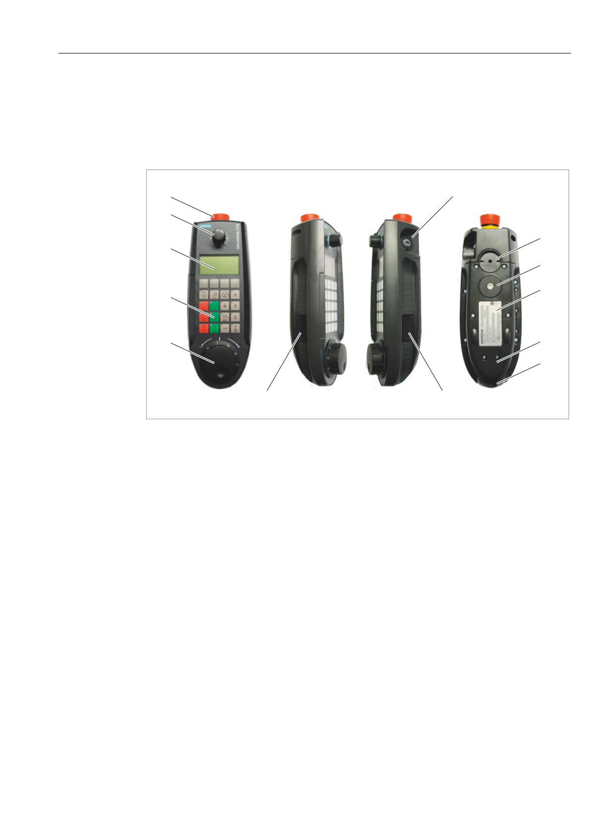
Handheld Terminal HT 2
1.2 Operator control and display elements
1.2
Operator control and display elements
1.2.1
Overview
(1)
Emergency stop button (stop button)
(2)
Rotary override switch
(3)
Display
(4)
Keyboard
(5)
Handwheel
(6)
Enabling button (left)
(7)
Enabling button (right)
(8)
Opening for the cable entry
(9)
Cable duct cover
(10)
Type plate
(11)
Standard position mounting bracket (optional: Retaining magnet)
(12)
Standard position retaining magnet (optional: Mounting bracket)
(13)
Key-operated switch
Image 1-1
Operator control and display elements of the HT 2
Handheld units
Manual, 03/2016, 6FC5397-1AP40-5BA3
9
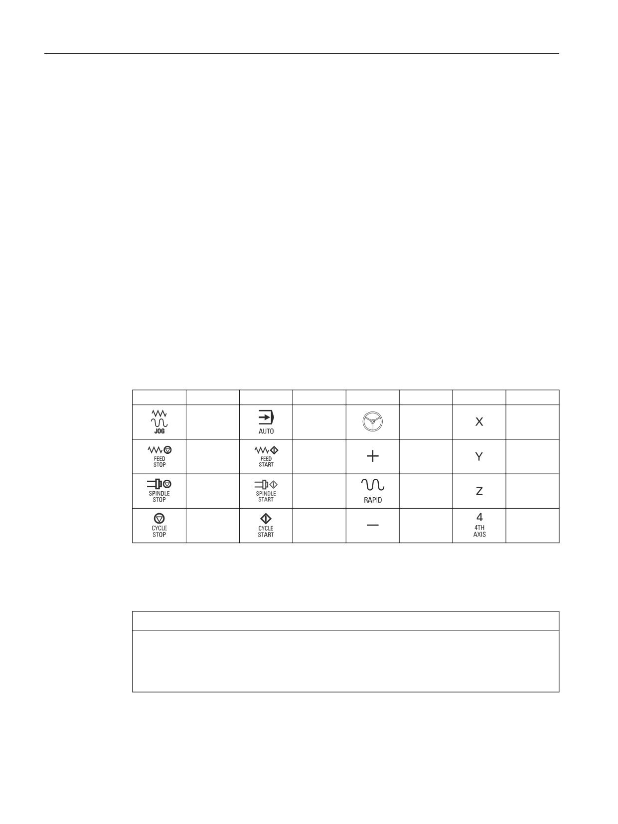
Handheld Terminal HT 2
1.2 Operator control and display elements
1.2.2
Description
Display
The Handheld Terminal HT 2 is equipped with an LCD display (black / white).
The display has a resolution of 168 x 72 pixels. This means that for a normal font of 16 pixels
high, 4 lines each with 16 characters can be displayed.
Keyboard
On the HT 2 there are a total of 20 keys each assigned 1 LED. Of which
● All 4 keys in the upper row of keys can be used as softkeys as well as system keys.
● The remaining 16 keys are reserved for the machine control.
When supplied from the factory, the HT 2 has 5 horizontal slide-in labels.
One of these slide-in labels is not printed. The remaining four slide-in labels have standard
symbols for the machine control printed on them.
The standard symbols used and their position on the slide-in labels are listed together with the
corresponding symbol number in the table.
Table 1-1
Standard symbols on the slide-in labels
-
(spec.)
-
(spec.)
-
(spec.)
-
(spec.)
7001
7015
7048
7011
7025
7026
7112
7022
7013
7124
7027
7028
7020
7021
7111
7029
Symbols that you specify can be printed on all of the slide-in labels. Blank films are available
for this purpose.
Information on the article number for the blank films and for printing as well as exchanging the
slide-in labels is provided in Section "Accessories" → "Slide-in labels".
NOTICE
Damage to the keys when using pointed or hard objects
Only use your fingers to touch the membrane keyboard and not sharp or hard objects, which
can damage or even destroy the keys. Further, please note that the touch pen is also not
suitable for using the membrane keyboard.
Handheld units
10
Manual, 03/2016, 6FC5397-1AP40-5BA3
Handheld Terminal HT 2
1.2 Operator control and display elements
Rotary override switch
The rotary override switch of the HT 2 has 19 positions.
The evaluation scale (0 to max.) is specified by the machine's manufacture in the form of
machine data.
Handwheel
The HT 2 handwheel has magnetic bearings.
A turning knob is integrated in the handwheel knob. This allows fast rotary motion to be
executed using a finger (run-on < 1 revolution).
Individual increments can be reliably moved at the machine - as the transition from one position
to another can be clearly sensed.
The handwheel operates with 100 pulses/revolution and has a cogging torque of approx. 1.5
Ncm (+/- 0.3). The max. speed is 1000 rpm
Emergency stop button
The red emergency stop mushroom pushbutton has a yellow ring.
Directly under the mushroom pushbutton, there is also a black ring which identifies the position
status of the emergency stop button.
State
Ring (black)
Visible
Not visible
Emergency stop button
Not pressed
Pressed
If an emergency stop is triggered, the button locks into place.
If the button is locked into place, it can be unlocked by rotating it to the right.
Emergency stop button
Press the red button in emergencies when
∎
people are at risk,
∎
there is the danger of machines or the workpiece being
damaged.
As a rule, when operating the emergency stop button, all drives
are brought to a standstill with max. braking torque.
Machine manufacturer
For other reactions to the emergency stop:
Refer to the machine tool manufacturer's instructions!
The signals are sent via the connecting cable to the terminal box or the connection module
and are available for further wiring.
Enabling button
The HT 2 has two enabling buttons that are logically grouped.
This allows the enabling function to be triggered by either the left or the right hand during
normal operation.
Handheld units
Manual, 03/2016, 6FC5397-1AP40-5BA3
11
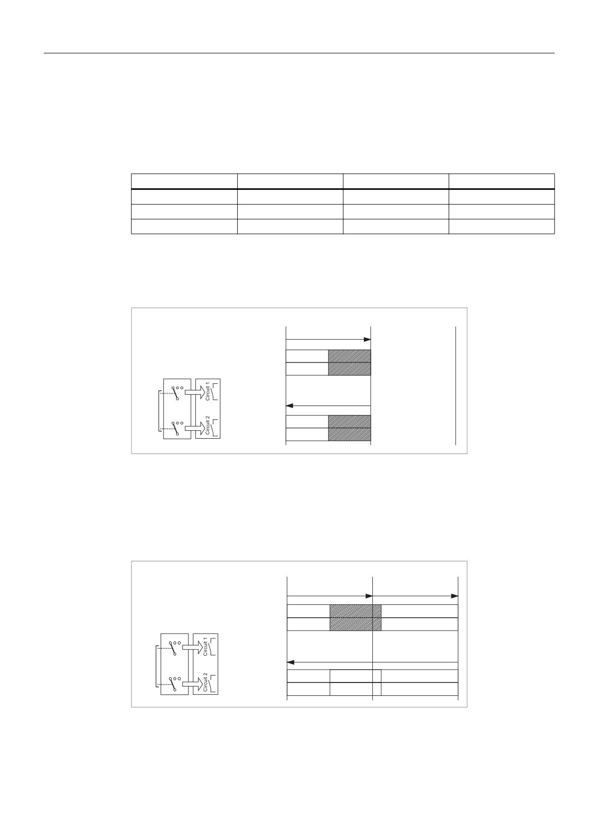
Handheld Terminal HT 2
1.2 Operator control and display elements
The enabling buttons comprise a 3-stage operator element and separate evaluation
electronics. They have a 2-circuit configuration.
The actuatior comprises two symmetrically arranged rockers whose position is determined
using electrical sensors and which is transferred to the evaluation electronics.
The enabling buttons can assume one of three different switch positions.
Switch position
Function
Enabling button
Switching contact
1
Zero position
Not actuated
Off (open)
2
Agreement
Actuated
On (closed)
3
Panic
Pressed
Off (open)
The switching sequences, shown in the diagrams are possible for the enabling buttons.
Normal actuation
Zero position → X → Agreement → Y → Zero position
[
=7[
&LUFXLW
2))
21
$JUHHPHQW
(YDOXDWLRQ
&LUFXLW
2))
21
EXWWRQ
HOHFWURQLFV
=7[
\
=7[
&LUFXLW
2))
21
=7[
&LUFXLW
2))
21
Image 1-2
Switching distance diagram for normal actuation
Panic actuation
Completely pressing the actuator to the panic position is evaluated by the fact that when
released, the agreement position is skipped.
Zero position → X → Agreement → U → Panic → Y → Zero position
[
X
=7
[
&LUFXLW
2))
21
2))
$JUHHPHQW
(YDOXDWLRQ
&LUFXLW
2))
21
2))
EXWWRQ
HOHFWURQLFV
=7[
Y
=7
[
&LUFXLW
2))
2))
2))
=7[
&LUFXLW
2))
2))
2))
Image 1-3
Switching distance diagram for panic actuation
Handheld units
12
Manual, 03/2016, 6FC5397-1AP40-5BA3
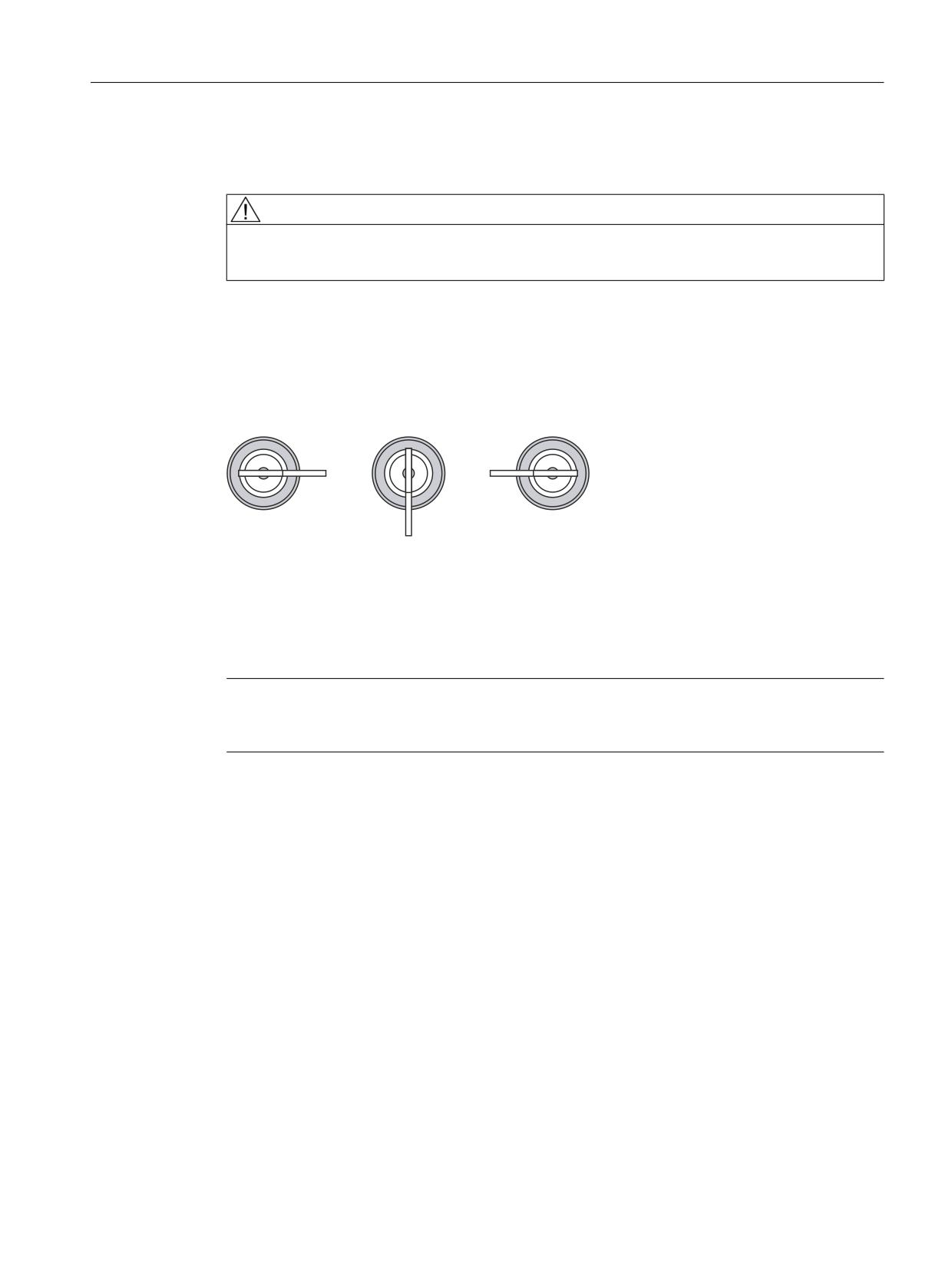
Handheld Terminal HT 2
1.2 Operator control and display elements
The signals are sent via the connecting cable to the terminal box or the connection module
and are available for further wiring.
WARNING
Danger of death resulting from the misuse of the enabling button
It is not permitted to fix the enabling button in the "Enable" position by mechanical means.
Key-operated switch
The key-operated switch has three positions: I - 0 - II.
,
,,
Image 1-4
Key-operated switch positions
The key can be removed in the switch position 0.
Remove the key after use. This avoids possible damage to the key if the HMI device falls down.
Note
The key for the key-operated switch is provided with the HMI device. Its coding is not specific
to the device. This means the key can be used on any Handheld Terminal HT 2.
Handheld units
Manual, 03/2016, 6FC5397-1AP40-5BA3
13
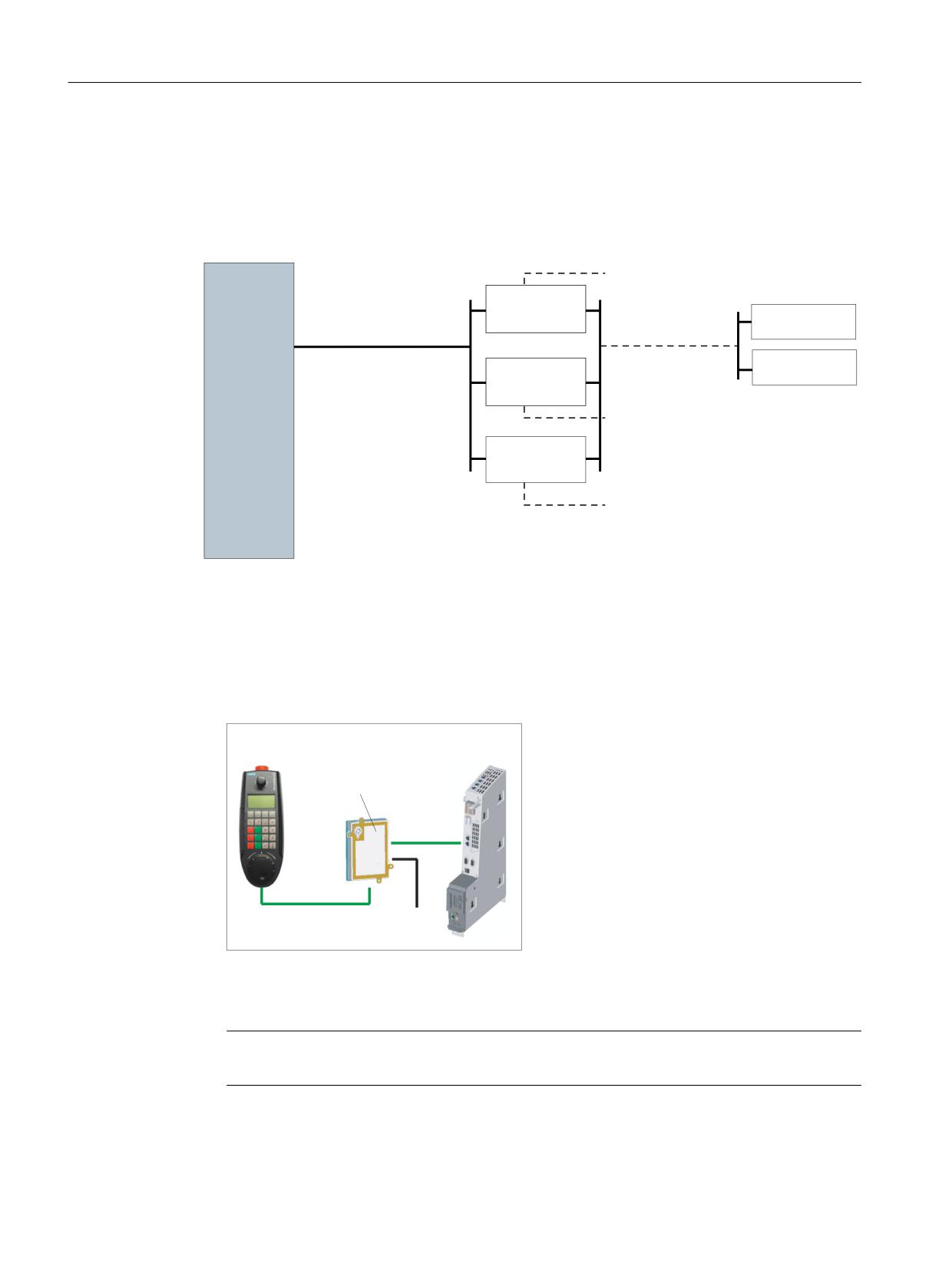
Handheld Terminal HT 2
1.3 Connecting
1.3
Connecting
1.3.1
Overview
Article no.
Emergency stop / enabling circuit
SINUMERIK
Prefabricated cable
Handheld
Terminal
Terminal box
HT 2
PN Basic / PN Plus
SINUMERIK
PCU 50.5
6XV1440-4B...
Ethernet cable
or
6FC5348-0AA08-3AA0
SINUMERIK
Connection module
NCU 7x0.3 PN
Basic PN
or
Emergency stop / enabling circuit
SINUMERIK
MPP 310 IEH/
MPP 483 IEH
Emergency stop / enabling circuit
Image 1-5
Connection overview HT 2
The Handheld Terminal HT 2 communicates with a control unit via
● PN Basic terminal box/PN Plus terminal box, or
● PN Basic connection module (for control cabinet installation) or
● MPP 310 IEH / MPP 483 IEH
&RQWUROOHUV
+7
1&8 [
&RQQHFWLRQ PRGXOH
%DVLF 31
(WKHUQHW 3URILQHW
6DIHW\
IDFWRU\ QHWZRUN
VLJQDOV
Image 1-6
Example: Communication between HT 2 and NCU 7x0 via the PN Basic connection
module
Note
The handwheel signals are only effective at a SINUMERIK control.
The system keys (machine control panel functionality / override) are transferred to a
SINUMERIK PLC as well as also to a SIMATIC CPU in a DB interface.
Handheld units
14
Manual, 03/2016, 6FC5397-1AP40-5BA3
Handheld Terminal HT 2
1.3 Connecting
The safety signals for Emergency Stop and enabling are retrieved from the terminal box, the
connection module or MPP via the connecting cable and connected to the safety relays in the
control cabinet.
If no HT 2 is connected, observe the following:
WARNING
Danger of death resulting from improper access
● After disconnection, the HT 2 must be locked away.
● Emergency Stop buttons that are inactive must not be identified as such or must be
inaccessible. This is to prevent the emergency stop button from being used inadvertently.
1.3.2
Terminal Box PN
1.3.2.1
Description
① LED displays
② Screwed joint for power supply cable and shield
③ Screwed joint for cable with supplementary stop and agreement button signals and for PLC-
accompanying signals
④ Connecting socket for the connector plug of the connecting cable (covered with dummy cap)
⑤ Screwed joint for process data line (Ethernet)
Image 1-7
Terminal Box PN
Note
Protection class IP65 at the terminal box is ensured with plugged-in HT 2 or plugged-in dummy
cap.
Handheld units
Manual, 03/2016, 6FC5397-1AP40-5BA3
15
Handheld Terminal HT 2
1.3 Connecting
The PN terminal box is available in two versions.
● PN Basic terminal box
The PN Basic terminal box can be used if no hot-plug capability is required. The Emergency
Stop circuit can be overridden here by external mechanisms.
● PN Plus terminal box
The PN Plus terminal box features hot-plug capability. This means that disturbance-free
hot-swapping is possible in operation. The Emergency Stop circuit is automatically
maintained while switching over.
Note
The exterior of the PN terminal box versions only differs in terms of what is printed on the side.
Clearance
The following clearances are required around the PN terminal box:
Additional references
You can find a detailed description in the operating instructions (compact) of the Mobile Panel
177 HMI device (WinCC flexible):
Handheld units
16
Manual, 03/2016, 6FC5397-1AP40-5BA3
Handheld Terminal HT 2
1.3 Connecting
1.3.2.2
PN Plus terminal box
The PN Plus terminal box differs from a PN Basic terminal box in that it has four relays mounted
on the board.
① Board
② Relays
Image 1-8
PN Plus terminal box
Switching states of the emergency stop circuit
HT 2
Emergency
Switching status, emergency stop circuit
Stop button
Connected
Not pressed
Emergency Stop circuit in the terminal box remains closed.
Connected
Pressed
The emergency stop circuit in the terminal box is open.
The system to be monitored is stopped.
Not connected
-
Emergency Stop circuit in the terminal box remains closed.
WARNING
Danger of death resulting from the inadvertent disconnection of the HT 2
If you disconnect the HT 2 from the PN Plus terminal box, the emergency stop circuit is closed,
thereby clearing the stop state of the system to be monitored. This occurs irrespective of
whether the emergency stop button has been pressed on the HT 2.
Handheld units
Manual, 03/2016, 6FC5397-1AP40-5BA3
17
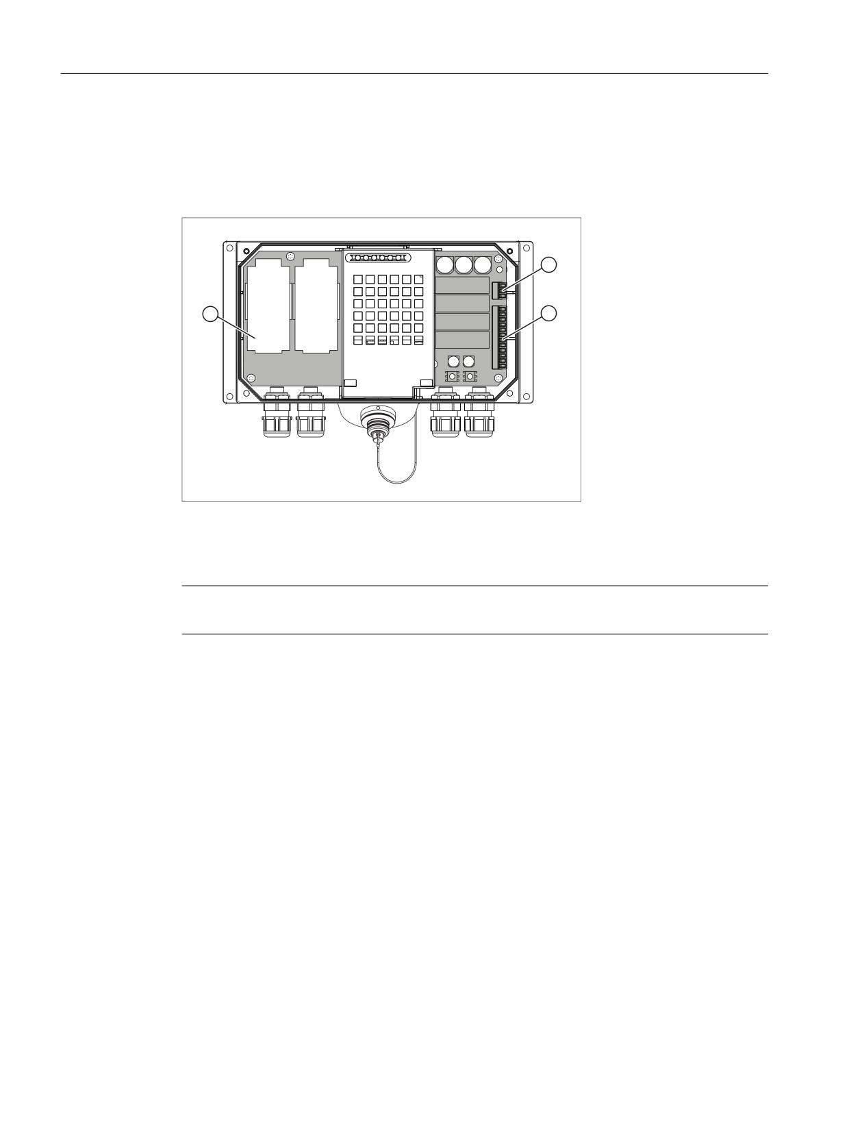
Handheld Terminal HT 2
1.3 Connecting
1.3.2.3
Interface assignment on the PN Plus terminal box
Location of the interfaces
① Fast connector
② Terminal strip 1
③ Terminal strip 2
Note
The PN Basic connection box has the same interfaces.
Handheld units
18
Manual, 03/2016, 6FC5397-1AP40-5BA3
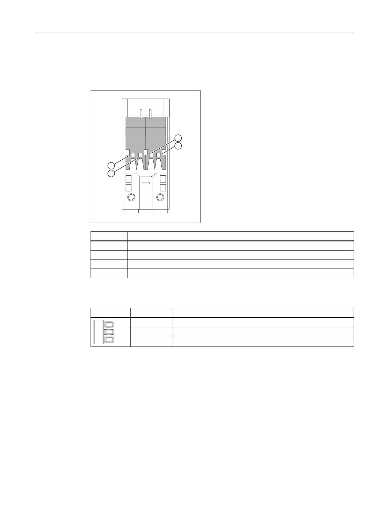
Handheld Terminal HT 2
1.3 Connecting
Fast Connector, 4-pin
The terminal box contains two fast connectors for connecting the PROFINET data cables. The
figure below illustrates the assignment of the fast connector:
Pin
Signal name
1
RD+
2
TD+
3
RD-
4
TD-
Terminal strip 1, for power supply, 3-pin
Pin
Signal name
1
PE
2
M24
3
P24
Handheld units
Manual, 03/2016, 6FC5397-1AP40-5BA3
19
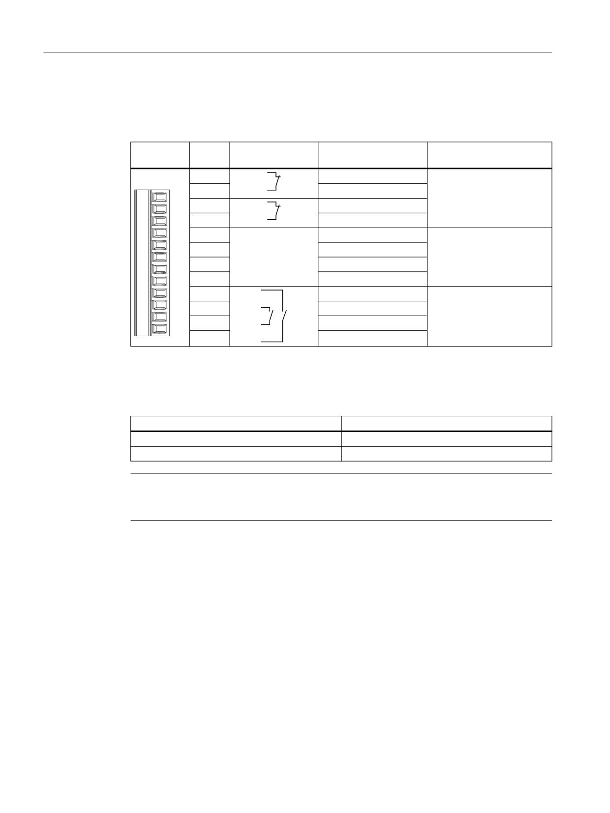
Handheld Terminal HT 2
1.3 Connecting
Terminal strip 2, 12-pin
The safety and additional functions are connected to this terminal strip. The terminal strip is
mechanically coded to prevent it from being confused with terminal strip 1.
Pin
Internal intercon-
Signal name
Circuit
nection
1
STOP13
Emergency Stop button
2
STOP14
3
STOP23
4
STOP24
5
+24 V 1)
Accompanying control sig-
nals
6
CTRL32 1) 2)
7
PRESENT31 3)
8
+24 V 1)
9
ENABLE2+
Enabling button
10
ENABLE1-
11
ENABLE1+
12
ENABLE2-
1)
Is only applicable for the PN Plus connection box
2)
Active, if the Emergency Stop pushbutton is pressed
3)
Active, if HT 2 / HT 8 is inserted
HT 2 / HT 8 to the connection box
Signal at digital input of the control
Not connected
"0"
Connected
"1"
Note
The "Emergency Stop button pressed" signal has no error detection facility and must, therefore,
not be used for safety-critical applications.
Handheld units
20
Manual, 03/2016, 6FC5397-1AP40-5BA3
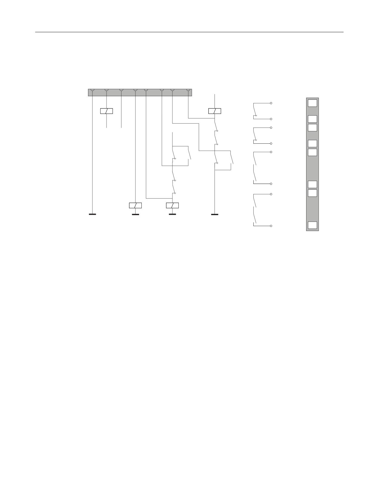
Handheld Terminal HT 2
1.3 Connecting
Typical circuit diagrams for PN Plus terminal box
9
7HUPLQDO VWULS
SLQ
6723
6723
6723
9
9
9
6723
9
&75/
35(6(17
9
Image 1-9
Circuit example 1: HT 2 not connected and power supply switched on:
Handheld units
Manual, 03/2016, 6FC5397-1AP40-5BA3
21