SINUMERIK 840D sl Hardware. Manual (2011-2020) - page 4
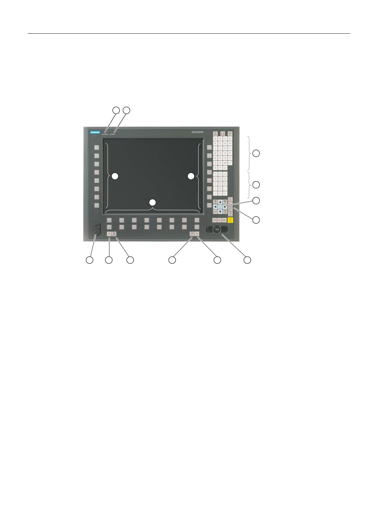
Operator panel front: OP 015AT
8.2 Operator controls and indicators
8.2
Operator controls and indicators
8.2.1
View
① Status LED POWER
② Status LED TEMP: Lit LEDs indicate increased wear.
③ Softkeys and direct keys
④ Alphabetic key group
⑤ Numeric key group
⑥ Cursor key group
⑦ Control key group
⑧ Mouse
⑨ Menu forward key
⑩ Menu select key
⑪ Softkeys
⑫ Machine area key
⑬ Menu back key
⑭ Front USB interface
Image 8-1
Front view of the OP 015AT operator panel front
Operator panels
112
Manual, 03/2016, 6FC5397-1AP40-5BA3
Operator panel front: OP 015AT
8.2 Operator controls and indicators
8.2.2
Keyboard
Keyboard
Several keys and keypads are installed on the operator panel front:
● The alphabetic block contains the letters A - Z and the space character.
● The numeric block contains the digits 0 - 9, and the characters "-", "/", "=", "+" and ".".
● The cursor key group is used to navigate on the screen.
● The control key group includes special functions.
● The mouse comprises the center actuation field (corresponds to the function of a tracker
ball) and two keys for the left and right mouse key.
● The softkeys call up functions that are available on the screen via a menu bar.
● The menu select key displays the area menu.
● The menu forward key enables an expansion of the horizontal softkey bar in the same menu.
● The machine area key switches directly into the "Machine" operating area.
● The menu back key returns to the higher-level menu, one window is closed.
Switching between upper and lower case
To toggle between upper and lower case letters, press the key combination Ctrl + Shift
Upper case is always activated as standard.
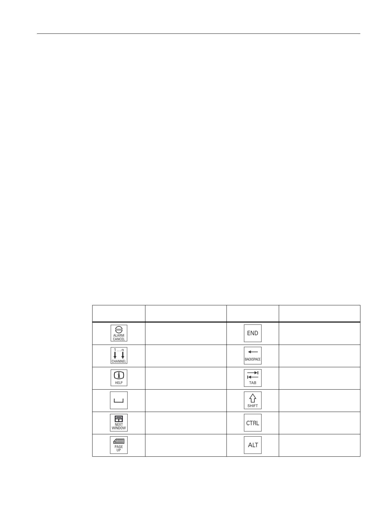
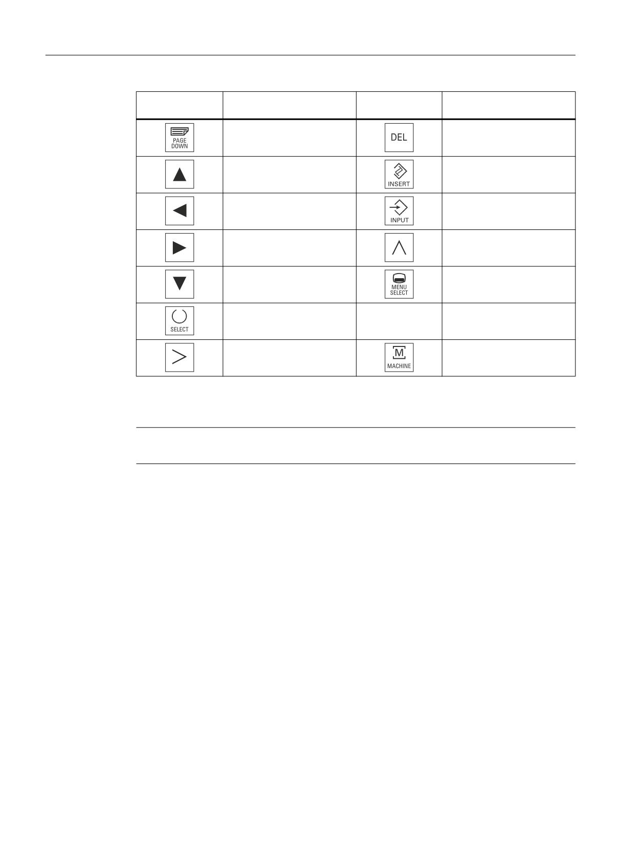
Overview of the key symbols
The key symbols used on the operator panel front are shown below along with the
corresponding function keys on the PC keyboard.
Key
Function corresponds to the
Key
Function corresponds to the
PC key function
PC key function
Esc
End
F11
Backspace
F12
Tab
Space
(only intended for internal key-
board changeover)
Home
Ctrl key
Page up
Alt key
Operator panels
Manual, 03/2016, 6FC5397-1AP40-5BA3
113
Operator panel front: OP 015AT
8.2 Operator controls and indicators
Key
Function corresponds to the
Key
Function corresponds to the
PC key function
PC key function
Page down
Delete
Cursor up
Insert
Cursor left
Enter
Cursor right
F9
Cursor down
F10
5 (in numeric key group)
A, ..., Z
<Shift> A, ..., Z
<Shift> F9
<Shift> F10
Display
Note
Pixel error according to DIN EN ISO 13406-2 Class II.
8.2.3
Screen saver
If a screen with high contrast is displayed unchanged for longer than an hour, then the
screensaver must be activated in order to protect the TFT display against so-called "burning
in" of the last displayed screen.
The time can be adapted individually. Further information can be found at:
Commissioning of Basic Software and Operating Software, SINUMERIK Operate (IM9)
Operator panels
114
Manual, 03/2016, 6FC5397-1AP40-5BA3
Operator panel front: OP 015AT
8.3 Interfaces
8.3
Interfaces
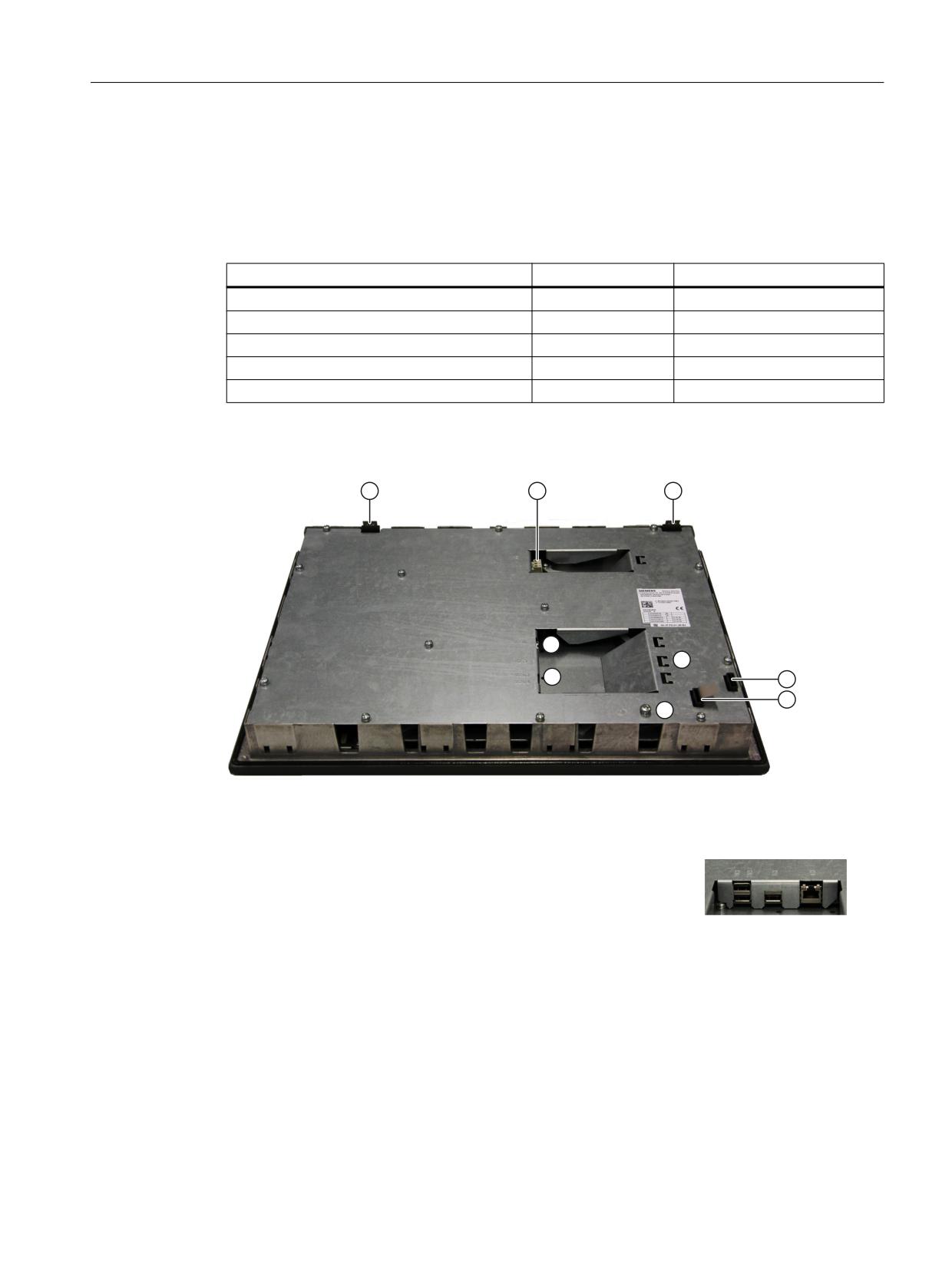
Overview
The OP 015AT operator panel front has the following interfaces:
Function
Designation
Type
Ethernet interface
X202
8-pin RJ45 socket
Double USB interface
X203 / X204
USB 2.0 Hi-Speed socket A
USB interface
X213
USB 2.0 Hi-Speed socket A
24 VDC power supply
X206
3-pin terminal block
Front USB interface
-
USB 1.1 Full Speed socket A
Rear
3(
9
9
① Teil 1
Slide-in labels for vertical softkeys (see Chpater Spare parts)
② X206
Power supply (with connector that can be screwed in place)
③ Teil 2
Slide-in labels for vertical softkeys (see Chpater Spare parts)
;
④
X202
Ethernet interface
;
;
;
⑤ X203 / X 204 /
USB interfaces
X213
⑥
-
Strain relief for connecting cables
⑦ Teil 3
Slide-in labels for horizontal softkeys (for these, there is no foil as template)
⑧ Teil 4
⑨
-
M5 grounding screw (for screw connection with cable lug)
Image 8-2
OP 015AT - Rear with interfaces
Operator panels
Manual, 03/2016, 6FC5397-1AP40-5BA3
115
Operator panel front: OP 015AT
8.4 Installation
Front
USB 1.1 Full Speed for connecting an external keyboard, mouse or USB flash drive (see Image
8-1 Front view of the OP 015AT operator panel front (Page 112)).
Note
Note that the electromagnetic compatibility of commercially available peripheral devices
operated via the USB interface is usually rated for office use only.
For industrial use, components with a higher degree of certification are recommended.
Pin assignment
The pin assignment of the interfaces, see "General information and networking" →
"Connecting".
8.4
Installation
8.4.1
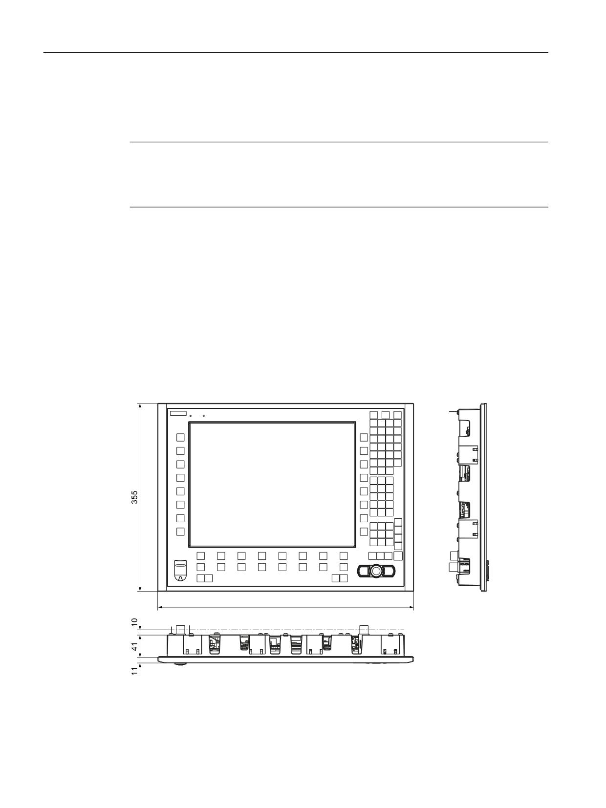
Mounting
Image 8-3
OP 015AT with TCU (integrated)
Operator panels
116
Manual, 03/2016, 6FC5397-1AP40-5BA3
Operator panel front: OP 015AT
8.4 Installation
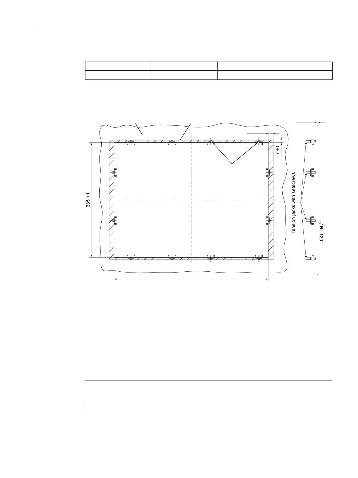
Table 8-1
Dimensions of the mounting opening
Width (mm)
Height (mm)
Mounting depth + clearance (mm)
450
335
42 + 10
Thanks to the tension jacks on the OP 015AT, drill-holes or screw holes are not needed.
This retaining method also enables the IP65 degree of protection (but only in conjunction with
a circumferential seal and when the protective USB cap is fitted).
0RXQWLQJ SDQHO
6HDOLQJ DUHD
s
3UHVVXUH SRLQWV IRU
WHQVLRQ MDFNV
,Q WKH VHDOLQJ DUHD
Image 8-4
Dimension sheet for installing the OP 015AT operator panel front
8.4.2
Softkey labeling
User-specific functions can be assigned to the horizontal and vertical softkey bars. Printed
labeling strips can be used to label the softkeys.
Blank labels are already installed on delivery.
To make the vertical labels, DIN A4 foils are available (see Chapter, "Spare parts"
→Overview (Page 119) ).
Note
Use the "Arial" font to format text. This font is comparable to the "Univers S57" font, used by
Siemens for the key labeling.
Operator panels
Manual, 03/2016, 6FC5397-1AP40-5BA3
117
Operator panel front: OP 015AT
8.5 Technical data
Procedure
1. Letter the matt side of the foil using a laser printer.
2. Cut the printed labels along the preprinted lines.
3. Insert the strips into the slots provided on the rear side of the operator front panel (see
Image 8-2 OP 015AT - Rear with interfaces (Page 115)).
8.5
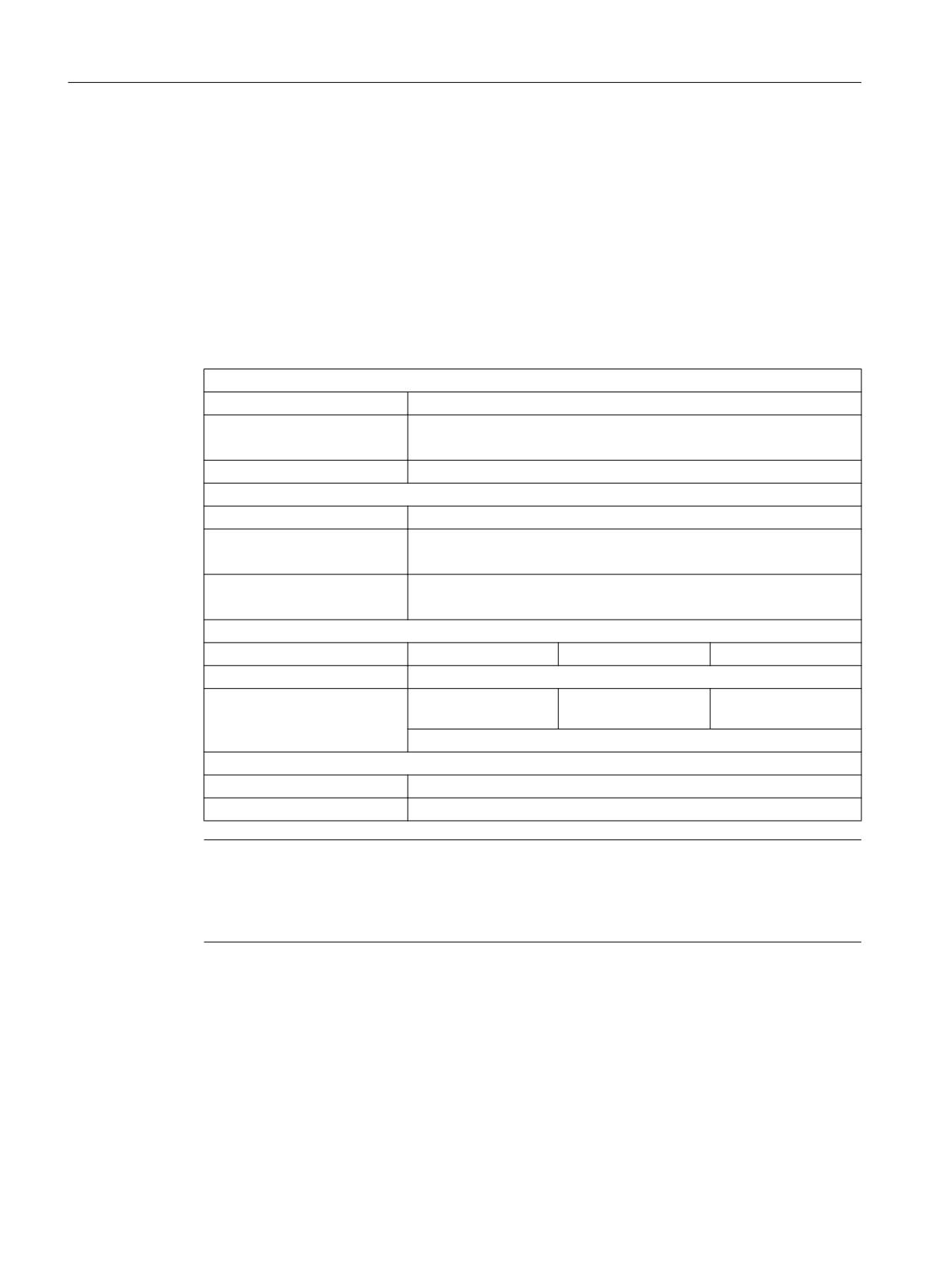
Technical data
Safety
Safety class
III; PELV according to EN 50178
Degree of protection accord-
Front side: IP65
ing to EN 60529
Rear side: IP00
Approvals
CE / cULus
Electrical data
Power supply
24 VDC
Current consumption
Typical, approx. 0.9 A
Max. approx. 2.4 A
Power consumption
Typical, approx. 22 W
Max. approx. 47.5 W
Mechanical data
Dimensions
Width: 483 mm
Height: 355 mm
Depth: 53 mm
Weight
Approx. 7.6 kg
Tightening torques, max.
Tension jack screws:
M3 screws:
M4 screws:
0.5 Nm
0.8 Nm
1.8 Nm
M5 grounding screw: 3 Nm
Display
Size / resolution
15" TFT / 1024 x 768 pixels
MTBF backlight
Typ. 50,000 h at 25º C (dependent on the temperature)
Note
Information about the climatic and mechanical environmental conditions is contained in the
associated section under:
"General notes and interconnection" → "Operational planning".
Operator panels
118
Manual, 03/2016, 6FC5397-1AP40-5BA3
Operator panel front: OP 015AT
8.6 Replacement parts
8.6
Replacement parts
8.6.1
Overview
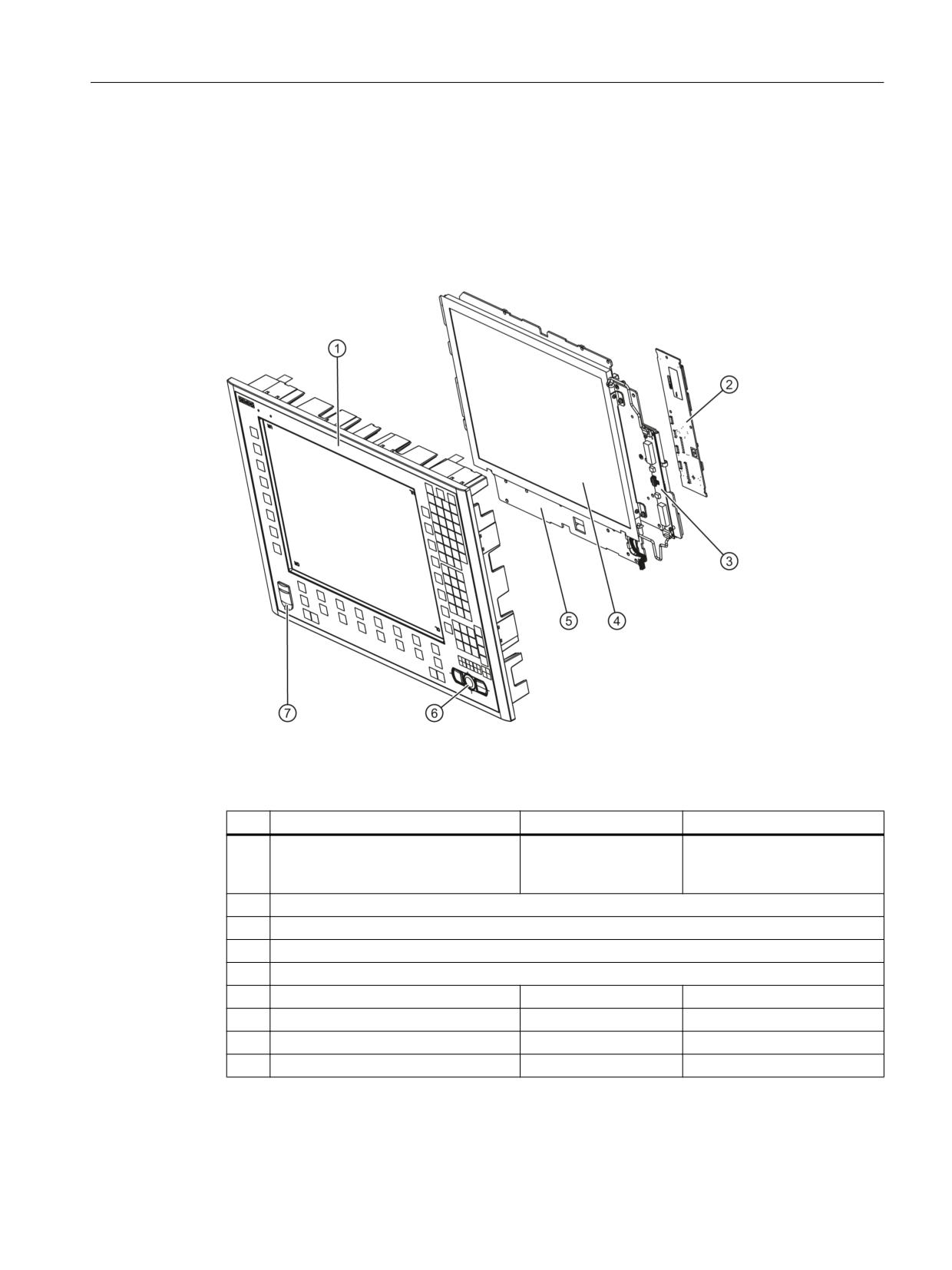
The diagram shows the OP 015AT operator panel front disassembled into its individual parts.
Image 8-5
Individual parts for the OP 015AT operator panel front
The components listed in the following table with an article number are available as spare parts.
Spare part
Article number
Remark
①
Operator panel front
A5E00405090
Without LCD unit, mouse,
USB port and keyboard con-
troller
②
Keyboard controller
③
Background lighting with backlight inverter
④
LCD unit
⑤
Display support
⑥
Mouse
6FC5247-0AF01-0AA0
⑦
USB caps
6FC5248-0AF05-0AA0
Set of 10
Tension jacks
6FC5248-0AF14-0AA0
Set of 9
Slide-in strips that can be labeled
6FC5248-0AF24-0AA0
Set with 3 foils, DIN A4
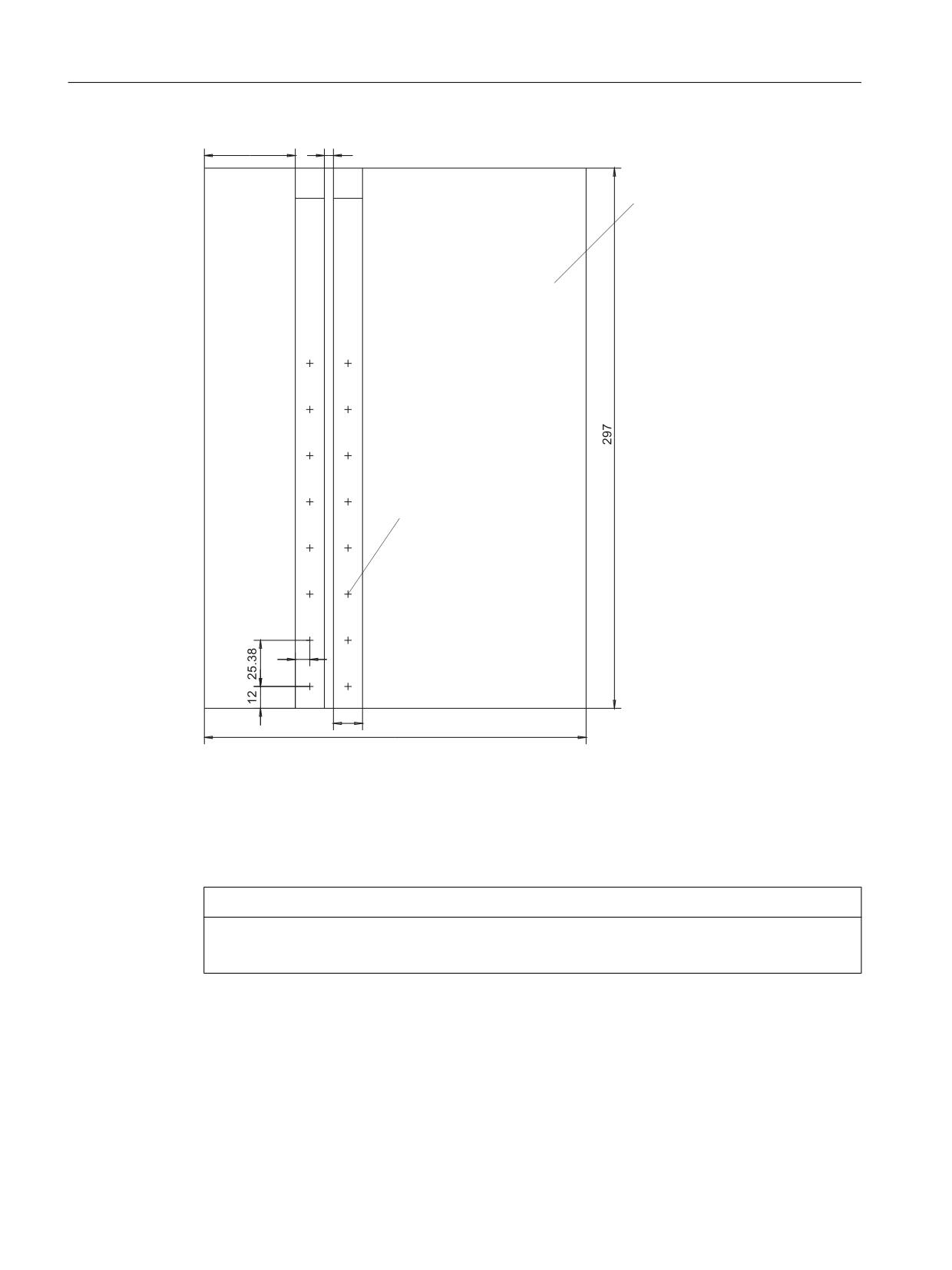
The dimensions for creating slide-in labels from the foil for labeling the vertical softkeys can
be seen in the following diagram.
Operator panels
Manual, 03/2016, 6FC5397-1AP40-5BA3
119
Operator panel front: OP 015AT
8.6 Replacement parts
3DUW
3DUW
)LOP ',1 $
&HQWHU RI WKH NH\
Image 8-6
Dimensions for slide-in labels
8.6.2
Replacement
NOTICE
Damage to sensitive components due to static electricity
Spare parts must always be replaced by properly trained personnel!
USB cap / tension jack
The replacement of the USB sealing cap and tension jacks will not be described since it is
simple and self-explanatory.
Operator panels
120
Manual, 03/2016, 6FC5397-1AP40-5BA3
Operator panel front: OP 015AT
8.6 Replacement parts
Operator panel front
When the operator panel front is replaced, the display, keyboard controller, mouse, and USB
interface can be used again. They are therefore disassembled and re-assembled after the
appropriate component has been replaced.
Note
We recommend reusing the keypad controller to prevent any loss of the control parameters
that have been programmed in.
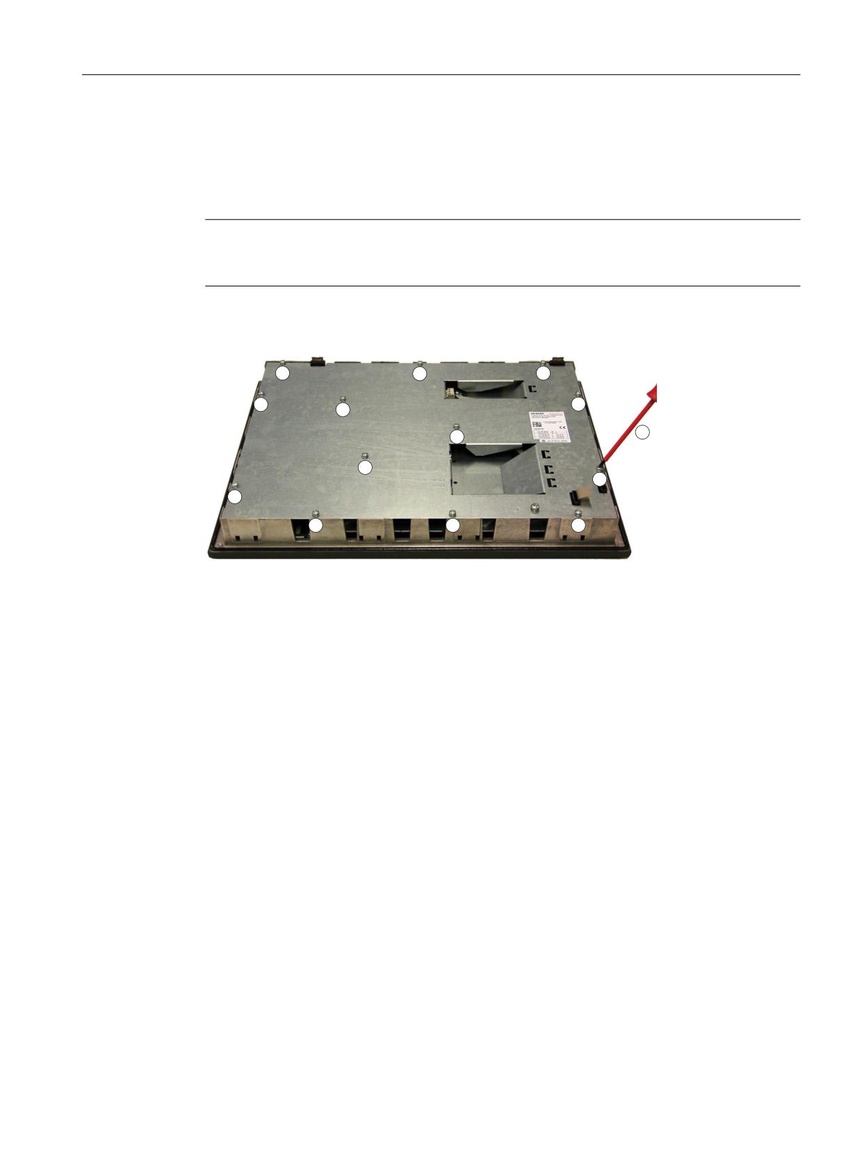
Expansion of the individual parts of the operator panel front
1
1
1
1
1
1
2
1
1
1
1
1
1
1
1. Place the OP 015AT on a soft horizontal surface. Loosen the 13 housing screws (M4)
① using a Torx screwdriver T25 ②.
2. Remove the cover.
Operator panels
Manual, 03/2016, 6FC5397-1AP40-5BA3
121
Operator panel front: OP 015AT
8.6 Replacement parts
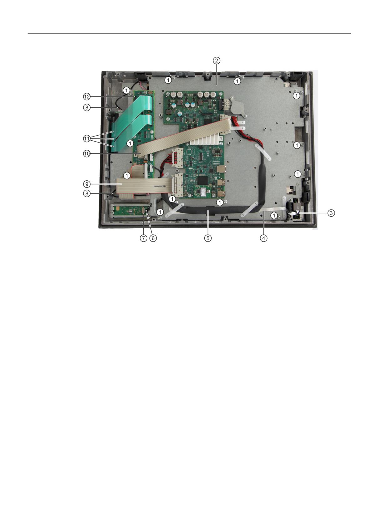
① Screws (M4) for display support
② Display support
③ USB interface
④ Ribbon cable for keyboard controller / USB interface
⑤ Display cable
⑥ Cable, mouse / keyboard controller
⑦ Connector, mouse interface
⑧ Backlight inverter cable
⑨ I/O USB cable
⑩ Direct key cable
⑪ Keyboard cables
⑫ Keyboard controller
Image 8-7
OP 015AT housing opened
Operator panels
122
Manual, 03/2016, 6FC5397-1AP40-5BA3
Operator panel front: OP 015AT
8.6 Replacement parts
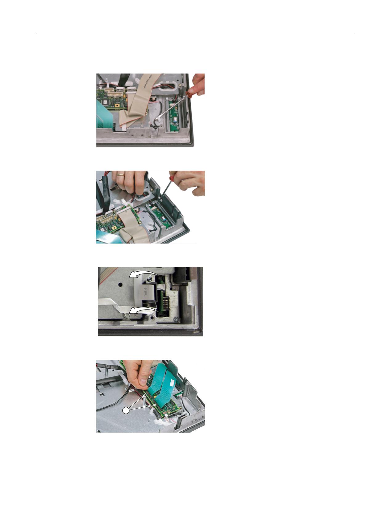
Cables, backlight inverter
3. Remove the two cables to the backlight in-
verter by lifting the clips with a flat screwdriver
and withdrawing the cables.
Connection of keyboard controller / mouse
4. Undo the connection between the keyboard
controller and the mouse by carefully pushing
the connector back with a screwdriver.
USB board
5. Release the connection to the keyboard con-
troller by releasing both retaining clamps next
to the USB board and withdrawing them.
Do not remove the cable from the board!
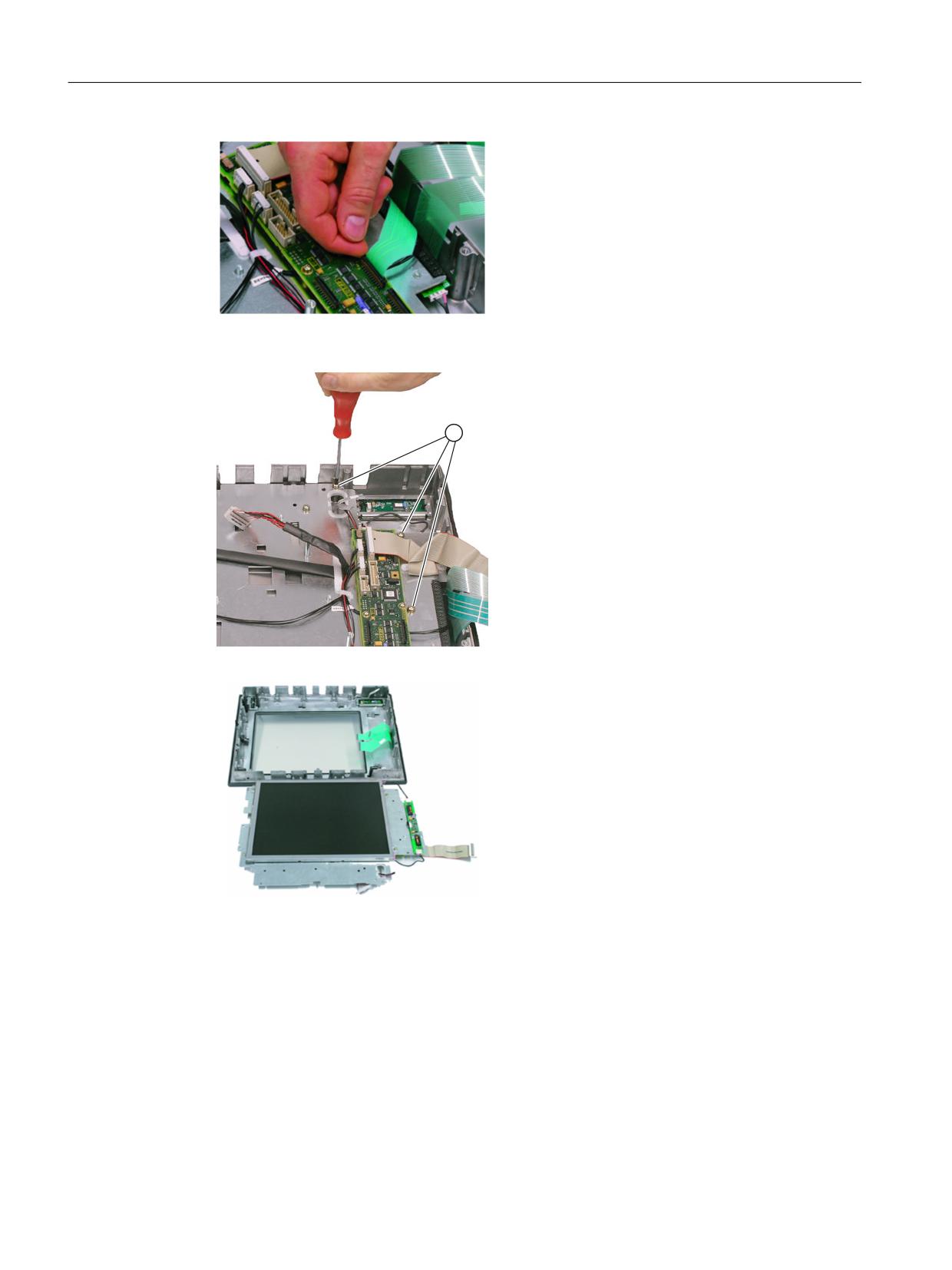
Keyboard cables
6. Disconnect the 3 keyboard cables by pushing
up the terminal holders ① on the keyboard
controller and pulling the keyboard cables out
of the holder.
Operator panels
Manual, 03/2016, 6FC5397-1AP40-5BA3
123
Operator panel front: OP 015AT
8.6 Replacement parts
For detailed information about removal and
insertion of membrane connectors, see "Gen-
eral information and networking", Chapter:
"Connecting", Section: "Handling membrane
connectors".
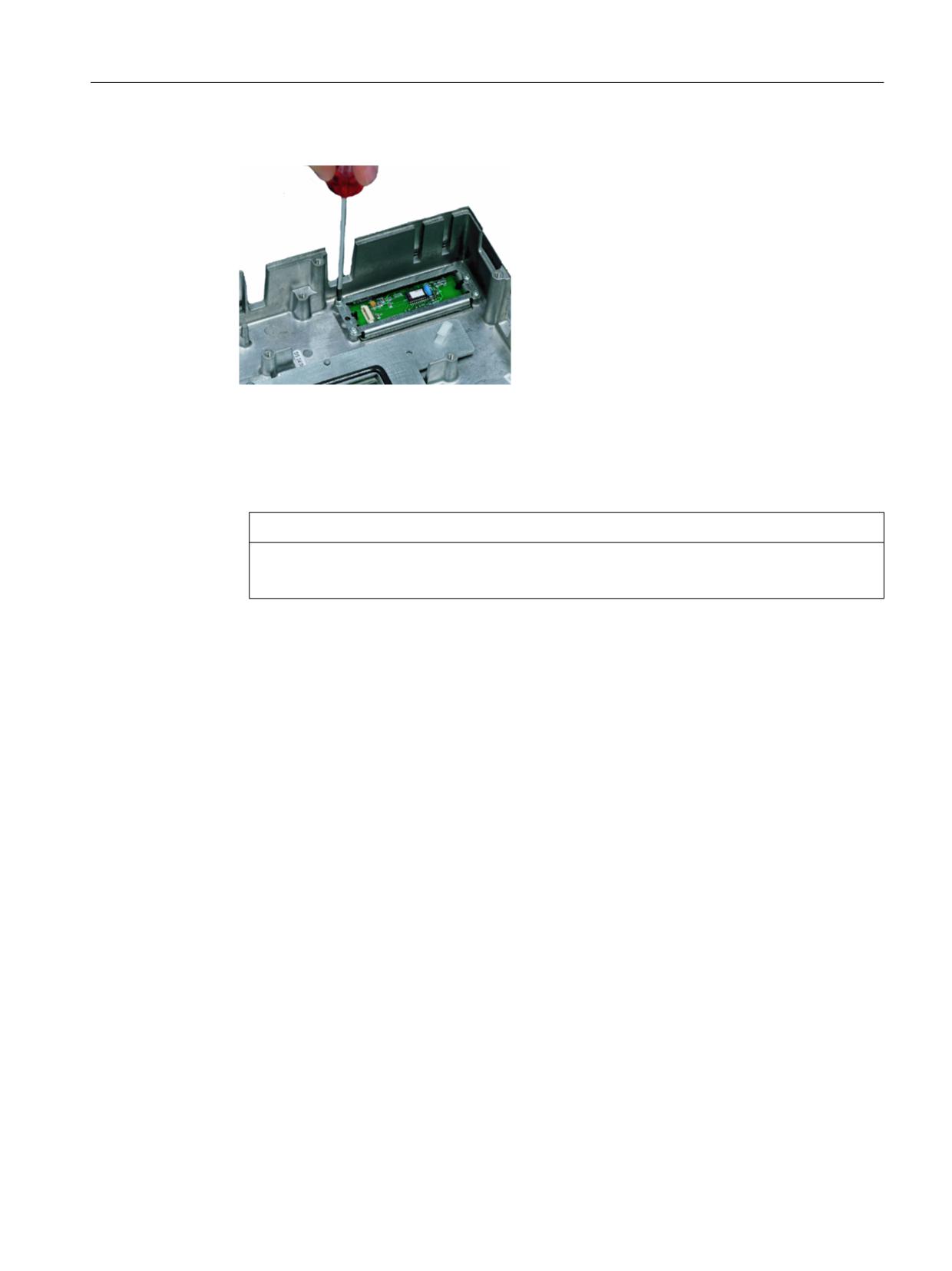
Display support
7. Remove the 12 screws ① from the display
support.
For the arrangement of the screws on the
display support, refer to Figure: "OP 015AT
housing opened".
8. Lift off the display support.
9. Lay the display support down on its back to
avoid damaging the display.
Operator panels
124
Manual, 03/2016, 6FC5397-1AP40-5BA3
Operator panel front: OP 015AT
8.6 Replacement parts
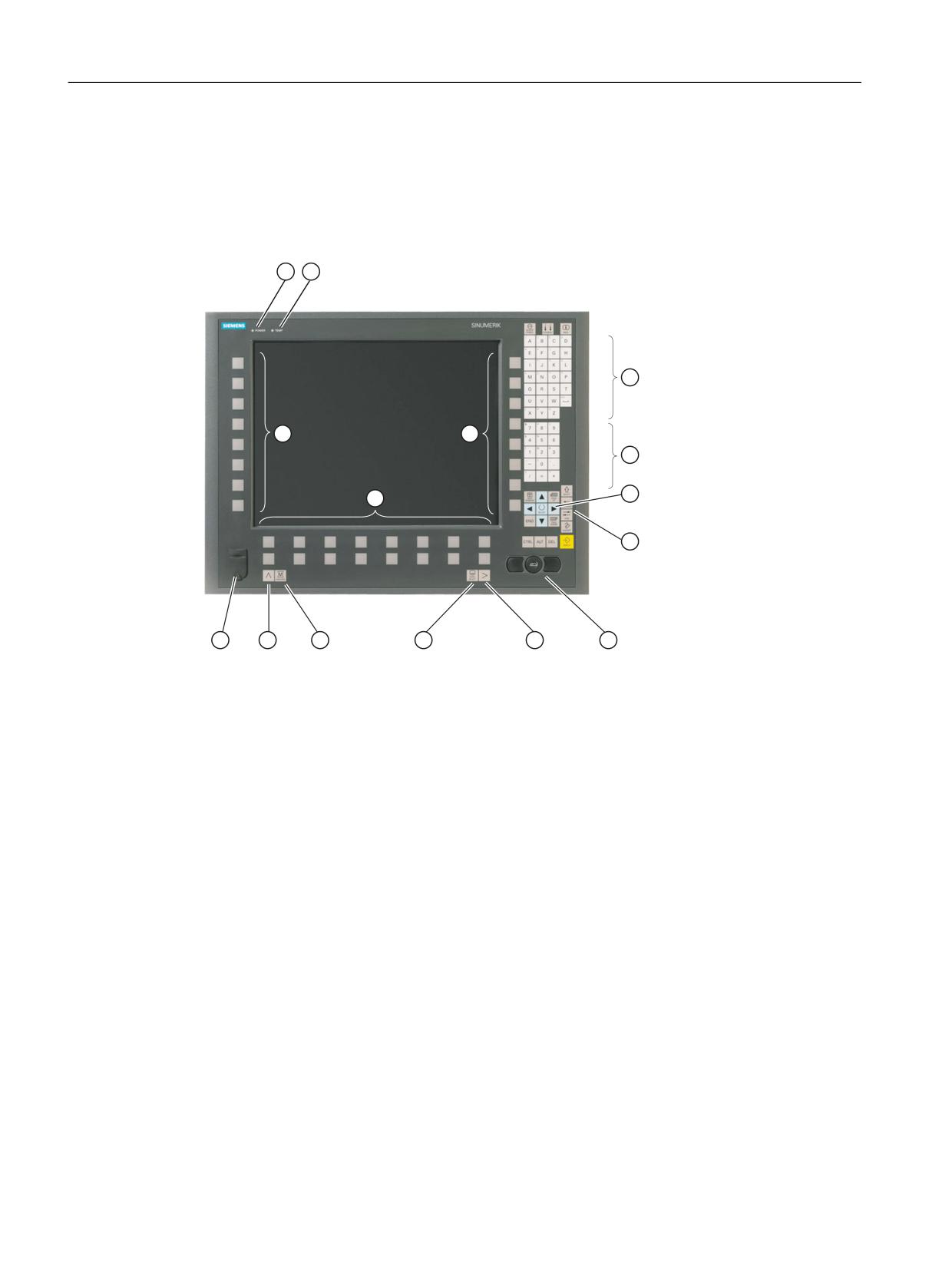
Mouse board
10. Loosen the 4 screws (M3) at the support for
the mouse board using a Torx screwdriver
T10. Lift off both the holder and the mouse
board.
Installing the individual parts of the operator panel front
1. Remove the transportation safety precautions (adhesive strip for securing cables) and the
screen protective foil from the inside.
2. Install the components in the new operator panel front in the order indicated:
NOTICE
Damage to the screws
Pay attention to the torques when tightening the screws (see Technical data (Page 118)).
2.1 Mouse board and bracket
2.2 Display support
Slightly bend the keyboard cables to the rear before installing the display carrier.
Otherwise, they could jam or be damaged and therefore no longer function.
2.3 USB board
Press the USB board into place until you hear it lock into the retaining clamps.
2.4 Keyboard cables
2.5 Connection of keyboard controller / mouse
2.6 Cables, backlight inverter
2.7 Cover
Operator panels
Manual, 03/2016, 6FC5397-1AP40-5BA3
125
Operator panel front: OP 015AT
8.6 Replacement parts
Operator panels
126
Manual, 03/2016, 6FC5397-1AP40-5BA3
Operator panel front: TP 015A
9
9.1
Description
The SINUMERIK TP 015A touch operator panel front and 15" TFT color display with a
resolution of 1024 x 768 pixels (XGA) and touch screen features a 62-key membrane keyboard
as well as 2 x (8 + 2) horizontal and 2 x 8 vertical softkeys and an integrated mouse. The
2 x 8 vertical softkeys can be used as direct keys.
The operator panel front is secured from the rear using special clamps supplied with the panel.
Validity
The description below applies to the TP 015A operator panel front.
Article number 6FC5203-0AF08-0AB2
Features
●
15" TFT flat screen (color) with resolution 1024 x 768 pixels
● Touch screen (analog resistive, 5-wire)
● Membrane keyboard with alphabetic, numeric, cursor, and control keypad
● Softkeys / direct keys:
-
2 x (8 + 2) horizontal rows of keys with softkey function
–
2 x 8 vertical rows of keys with softkey and direct key function
– Direct keys connectable via direct key / handwheel connection module or MCP interface
PN (optional), machine control panel, TCU or directly to the I/Os
● Shift key for switchover to the second key level (not for switching over the letters, since
they are uppercase only)
● Integrated mouse
● Status LEDs for power supply and overtemperature
● USB front interface (USB 1.1 Full Speed)
● Degree of protection IP65 (front)
● Attachment: Tension jacks at the rear
● Can be combined with PCU, TCU
Operator panels
Manual, 03/2016, 6FC5397-1AP40-5BA3
127
Operator panel front: TP 015A
9.2 Operating and display elements
9.2
Operating and display elements
9.2.1
View
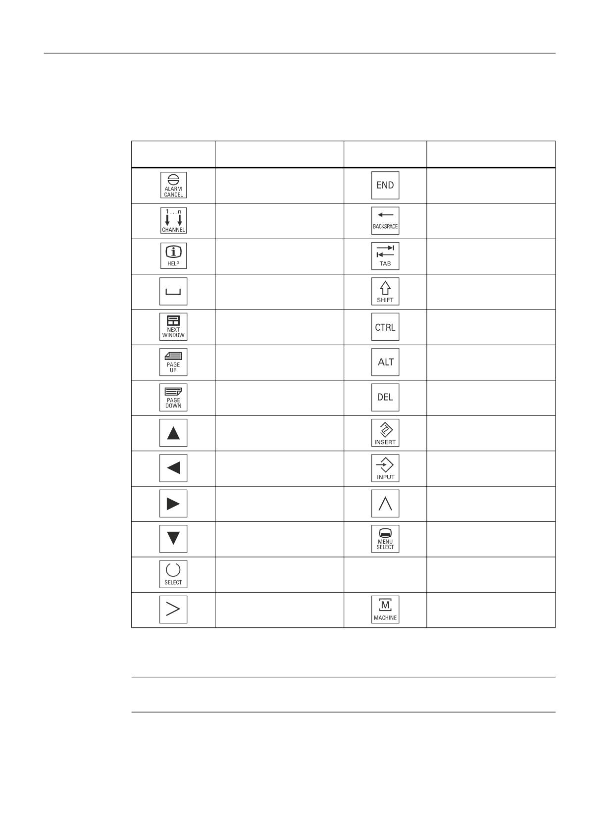
① Status LED POWER
② Status LED TEMP: Lit LEDs indicate increased wear.
③ Softkeys and direct keys
④ Alphabetic key group
⑤ Numeric key group
⑥ Cursor key group
⑦ Control key group
⑧ Mouse
⑨ Menu forward key
⑩ Menu select key
⑪ Softkeys
⑫ Machine area button
⑬ Menu back key
⑭ Front USB interface
Image 9-1
Front view, TP 015A operator panel front
Operator panels
128
Manual, 03/2016, 6FC5397-1AP40-5BA3
Operator panel front: TP 015A
9.2 Operating and display elements
9.2.2
Operation
The operator panel front is operated by
● Using the touch screen to select the application-specific functions, e.g. by touching one of
the displayed buttons.
● Softkeys
● Keys
● Mouse
NOTICE
Damage to the operator elements
Do not touch the operating elements with pointed or hard objects. This may considerably
reduce their service lives.
9.2.3
Keyboard
Keyboard
Several keys and keypads are installed on the operator panel front:
● The alphabetic block contains the letters A - Z and the space character.
● The numeric block contains the digits 0 - 9, and the characters "-", "/", "=", "+" and ".".
● The cursor key group is used to navigate on the screen.
● The control key group includes special functions.
● The mouse comprises a touchpad, for finger operation, as well as for cursor navigation and
also for the left and right mouse buttons.
● The softkeys call up functions that are available on the screen via a menu bar.
● The "Menu back" key switches back to the higher-level horizontal menu.
● The "Menu forward" key advances in the extended horizontal softkey bar.
● The "Menu select" key calls the main menu to select the operating area.
● The "Machine area" key selects the "Machine" operating area.
Switching between upper and lower case
To toggle between upper and lower case letters, press the key combination Ctrl + Shift
Upper case is always activated as standard.
Operator panels
Manual, 03/2016, 6FC5397-1AP40-5BA3
129
Operator panel front: TP 015A
9.2 Operating and display elements
Overview of the key symbols
The key symbols used on the operator panel front are shown in the overview along with the
corresponding function keys on the PC keyboard.
Key
Function corresponds to the
Key
Function corresponds to the
PC key function
PC key function
Esc
End
F11
Backspace
F12
Tab
Space
(only intended for internal key-
board changeover)
Home
Ctrl key
Page up
Alt key
Page down
Delete
Cursor up
Insert
Cursor left
Enter
Cursor right
F9
Cursor down
F10
5 (in numeric key group)
A, ..., Z
<Shift> A, ..., Z
<Shift> F9
<Shift> F10
Display
Note
Pixel error according to DIN EN ISO 13406-2 Class II.
Operator panels
130
Manual, 03/2016, 6FC5397-1AP40-5BA3
Operator panel front: TP 015A
9.3 interfaces
9.2.4
Screen saver
If a screen with high contrast is displayed unchanged for longer than an hour, then the
screensaver must be activated in order to protect the TFT display against so-called "burning
in" of the last displayed screen.
The time can be adapted individually. Further information can be found at:
Commissioning of Basic Software and Operating Software, SINUMERIK Operate (IM9)
9.3
interfaces
Front
USB 1.1 Full Speed (type A) for connecting an external keyboard, mouse and USB flash drive
(see Image 9-1 Front view, TP 015A operator panel front (Page 128)).
Note
Note that the electromagnetic compatibility of commercially available peripheral devices
operated via the USB interface is usually rated for office use only.
For industrial use, components with a higher degree of certification are recommended.
Rear
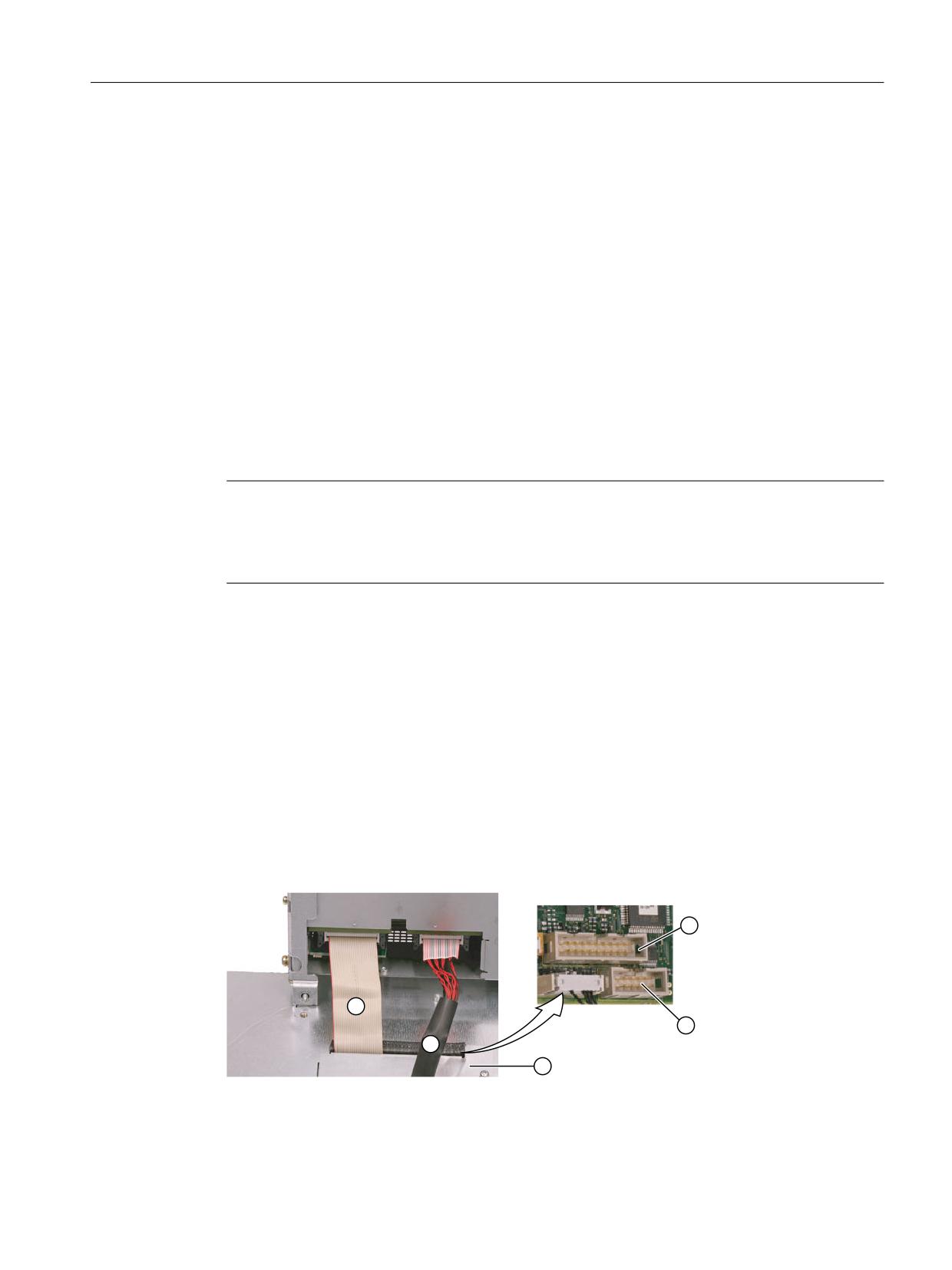
● Two cables for connecting the PCU:
- I/O-USB cable K1 ⑤:
all signals, which in addition to the display interface, are required to connect operator
panel fronts (e.g. supply voltages)
- Display cable K2 ④
Below the interface cover ③:
● Direct key interface X11 ①: Signals from the 16 "vertical softkey" direct keys
● Interface X12 (reserved) ②
Image 9-2
TP 015A - connections at the rear of the enclosure: Connections to the PCU
Operator panels
Manual, 03/2016, 6FC5397-1AP40-5BA3
131
Operator panel front: TP 015A
9.4 Mounting
Pin assignment
For more detailed information, see "General information and networking", Chapter:
"Connection".
9.4
Mounting
9.4.1
Preparation for mounting
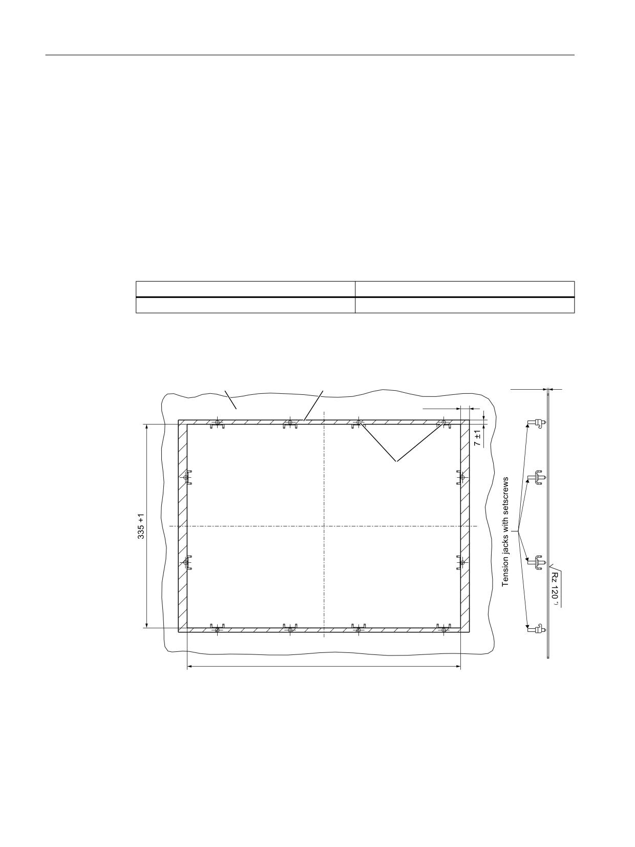
Table 9-1
Dimensions of the mounting opening
Width (mm)
Height (mm)
450
335
Thanks to the tension jacks on the TP 015A, drill-holes or screw holes are not needed.
This retaining method also enables the IP65 degree of protection (but only in conjunction with
a circumferential seal and when the protective USB cap is fitted).
0RXQWLQJ SDQHO
6HDOLQJ DUHD
s
3UHVVXUH SRLQWV IRU
WHQVLRQ MDFNV
,Q WKH VHDOLQJ DUHD
Image 9-3
Dimension sheet for mounting the TP 015A operator panel front
Operator panels
132
Manual, 03/2016, 6FC5397-1AP40-5BA3

Operator panel front: TP 015A
9.4 Mounting
9.4.2
Assembling TP 015A and PCU
The assembly functions in the same way as described in Section Assembling an OP 015A and
a PCU (Page 96).
9.4.3
Mounting on the mounting wall
The clearance at the rear of the PCU/TCU must be at least 10 mm to ensure sufficient
ventilation.
For more detailed information, please refer to the relevant PCU sections and in "General
information and networking", Section: "Application planning", Section: "Climatic and
mechanical environmental conditions" → "Cooling".
NOTICE
Impermissible mounting positions can cause malfunctions
Observe the permissible mounting position: Deviating by up to 5º from the vertical.
This value can be further restricted by mounted components (e.g. PCU).
Procedure
1. Insert the assembled components (operator panel front and PCU) from the front into the
panel cutout (see Image 9-3 Dimension sheet for mounting the TP 015A operator panel
front (Page 132)).
2. Secure the operator panel front in the panel cutout from the rear using the twelve tension
jacks by tightening the setscrews (torque 0.5 Nm).
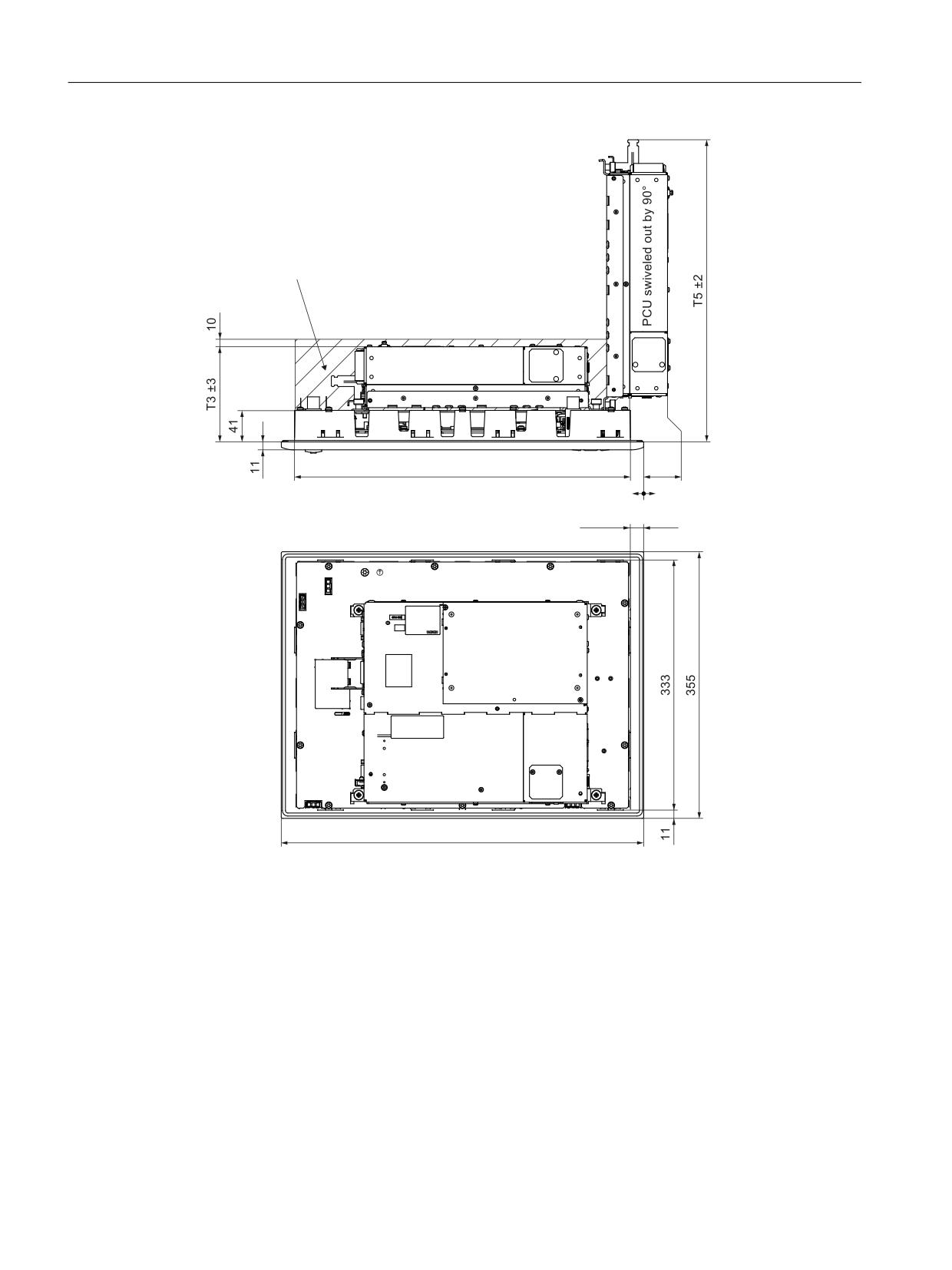
Table 9-2
Dimensions to be observed when installing
Mounting depth T3 + clear-
Opening depth T5
Protrusion P
ance (mm)
(mm)
(mm)
PCU 50.5
127 + 10
402
32
TCU x0.2
76 + 10
376
-19
Operator panels
Manual, 03/2016, 6FC5397-1AP40-5BA3
133
Operator panel front: TP 015A
9.4 Mounting
&OHDUDQFH IRU FDEOHV DQG YHQWLODWLRQ
3&8 LQ WKH HQG SRVLWLRQ
s
s
s
Image 9-4
Attaching the PCU to the TP 015A operator panel front
9.4.4
Touchscreen calibration
Whenever a new operator panel front is connected, a screen calibration must be performed.
Procedure
For a description of the calibration, refer to Chapter Touchscreen calibration (Page 249).
Operator panels
134
Manual, 03/2016, 6FC5397-1AP40-5BA3
Operator panel front: TP 015A
9.5 Technical specifications
9.4.5
Softkey labeling
User-specific functions can be assigned to the two vertical softkey bars. Printed labeling strips
can be used to label the softkeys.
Blank labels are already factory-installed.
DIN A4 films are available for preparing the vertical strips. You can find the article number in
Section "Spare parts" → "Overview".
Note
Use the "Arial" font to format text. This font is comparable to the "Univers S57" font, used by
Siemens for the key labeling.
Procedure
1. Label the mat side of the film with a laser printer or another printer that allows "Film" to be
set as a printable medium.
2. Cut the printed labels along the preprinted lines.
3. Insert the labeling strips into the slits provided from the rear of the operator panel front (refer
to figure: “TP 015A housing open” in section: "Spare parts" → "Replacement".
Note
In order to facilitate insertion of the "Teil 1" strip when the PCU is mounted, it is
recommended that you
- unscrew the four retaining screws of the PCU and
- swing the PCU up.
Once you have inserted the strip, swing the PCU back to the operator panel and secure by
tightening the screws.
9.5
Technical specifications
Safety
Safety class
III; PELV according to EN 50178
Degree of protection accord-
Front side: IP65
ing to EN 60529
Rear side: IP00
Approvals
CE / cULus
Electrical data
Power supply
Display
Backlight inverter
Logic / USB
(via K1 and K2)
Voltage
4.9 V - 5.25 V
12 V +/- 5%
5.0 V - 5.2 V
Current (typ./max.)
approx. 420/700 mA
approx. 900/1100 mA
approx. 350/1050 mA
Power consumption
Typical, approx. 15 W
Maximum approx. 25 W
Operator panels
Manual, 03/2016, 6FC5397-1AP40-5BA3
135
Operator panel front: TP 015A
9.6 Spare parts
Mechanical data
Dimensions
Width: 483 mm
Height: 355 mm
Depth: 53 mm
Weight
Approx. 8.4 kg
Max. tightening torques:
Tension jack screws:
M3 screws:
M4 screws:
0.5 Nm
0.8 Nm
1.8 Nm
Display
Size / resolution
15" TFT / 1024 x 768 pixels
MTBF backlight
typ. 50,000 h at 25º C (dependent on the temperature)
Note
Information about the climatic and mechanical environmental conditions is contained in the
associated section under:
"General notes and interconnection" → "Operational planning".
9.6
Spare parts
9.6.1
Overview
The diagram shows the TP 015A operator panel front dismantled into its individual parts.
Image 9-5
Individual parts for the TP 015A operator panel front
Operator panels
136
Manual, 03/2016, 6FC5397-1AP40-5BA3
Operator panel front: TP 015A
9.6 Spare parts
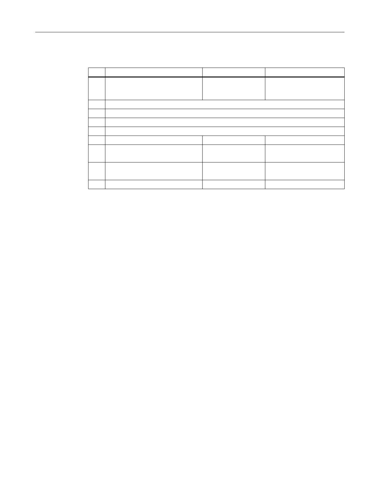
The components listed in the following table with an article number are available as spare parts.
Spare part
Article number
Remark
①
Operator panel front
A5E01136461
Without LCD unit, mouse,
USB port and keyboard con-
troller
②
Keyboard controller
③
Background lighting with backlight inverter
④
LCD unit
⑤
Display support
⑥
USB mouse
6FC5247-0AF01-0AA0
⑦
USB caps
6FC5248-0AF05-0AA0
Set of 10
Tension jacks
6FC5248-0AF14-0AA0
Set of 9
Slide-in strips that can be labeled
6FC5248-0AF24-0AA0
Set with 3 foils, DIN A4
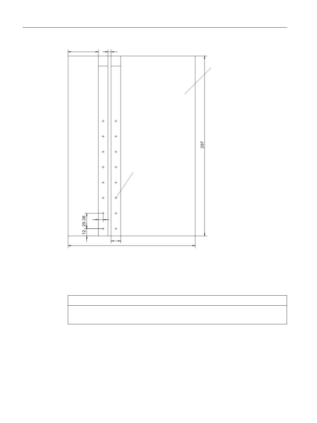
The dimensions for creating slide-in labels from the foil for labeling the vertical softkeys can
be seen in the following diagram.
Operator panels
Manual, 03/2016, 6FC5397-1AP40-5BA3
137
Operator panel front: TP 015A
9.6 Spare parts
3DUW
3DUW
)LOP ',1 $
&HQWHU RI WKH NH\
Image 9-6
Dimensions for slide-in labels
9.6.2
Replacement
NOTICE
Risk of damage to sensitive components due to static electricity
Spare parts must always be replaced by properly trained personnel!
USB cap / tension jack
The replacement of the USB sealing cap and tension jacks will not be described since it is
simple and self-explanatory.
Operator panels
138
Manual, 03/2016, 6FC5397-1AP40-5BA3
Operator panel front: TP 015A
9.6 Spare parts
Operator panel front
When the operator panel front is replaced, the display, keyboard controller, touch controller,
mouse and USB interface can be used again. They are therefore disassembled and
reassembled after the appropriate component has been replaced.
Note
We recommend reusing the keypad controller to prevent any loss of the control parameters
that have been programmed in.
Dismounting individual parts from the operator panel front
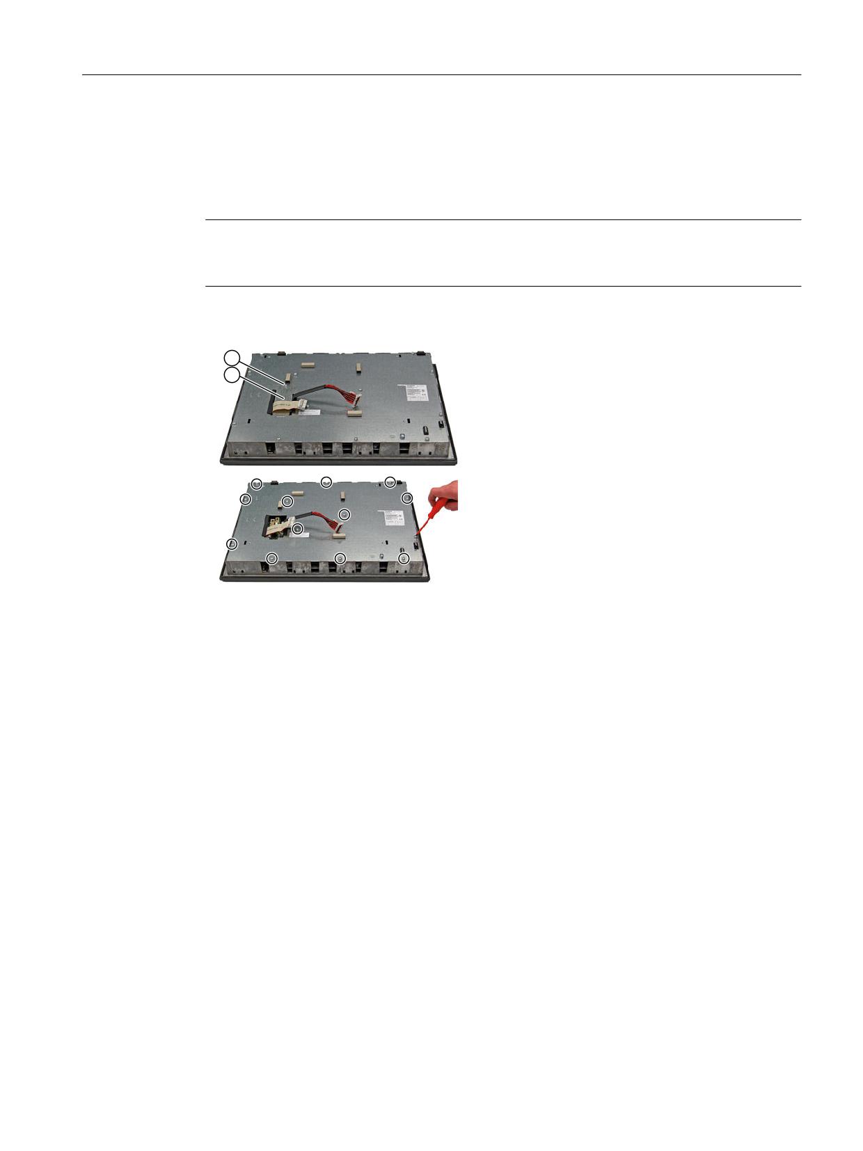
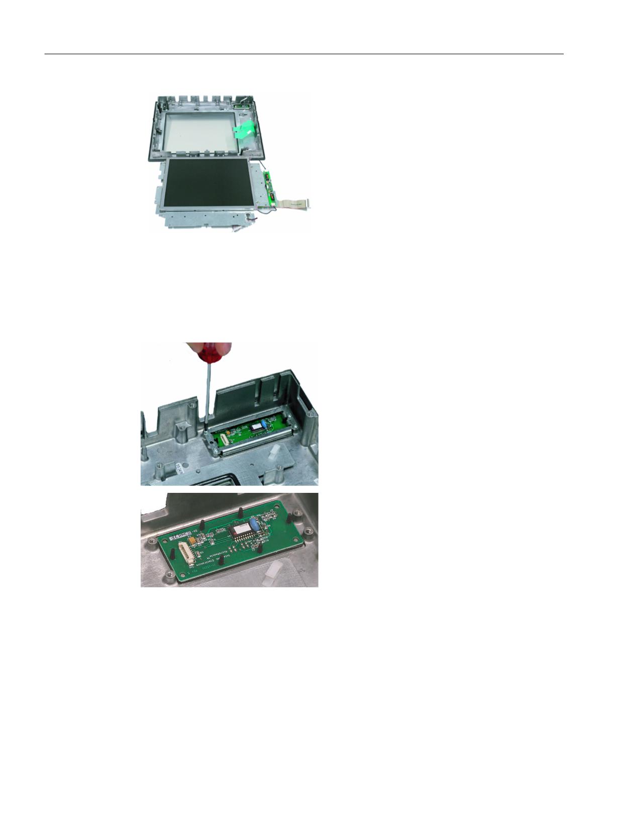
1. Place the TP 015A on a soft, horizontal sup-
port.
Remove the retaining screw (M3) ① from the
cover plate ② and lift off the cover plate.
2. Release the 13 housing screws (M4).
3. Lift off the cover.
Operator panels
Manual, 03/2016, 6FC5397-1AP40-5BA3
139
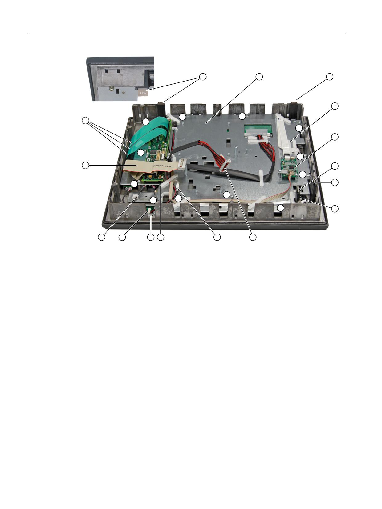
Operator panel front: TP 015A
9.6 Spare parts
① Screws (M4) for display support
② Slide-in labels (Teil 1)
③ Display support
④ Slide-in labels (Teil 2)
⑤ Retainer for the cable of the touch controller
⑥ Touch controller
⑦ Slide-in labels (Teil 4)
⑧ Slide-in labels (Teil 3)
⑨ USB interface
⑩ Display cable K2
⑪ Ribbon cable keyboard controller / USB connection
⑫ Retainer for the mouse / keyboard controller cable
⑬ Interface for the mouse
⑭ Cable plug for mouse / keyboard controller
⑮ Backlight inverter cable
⑯ I/O USB cable K1
⑰ Keyboard cables
Image 9-7
TP 015A housing opened
Operator panels
140
Manual, 03/2016, 6FC5397-1AP40-5BA3
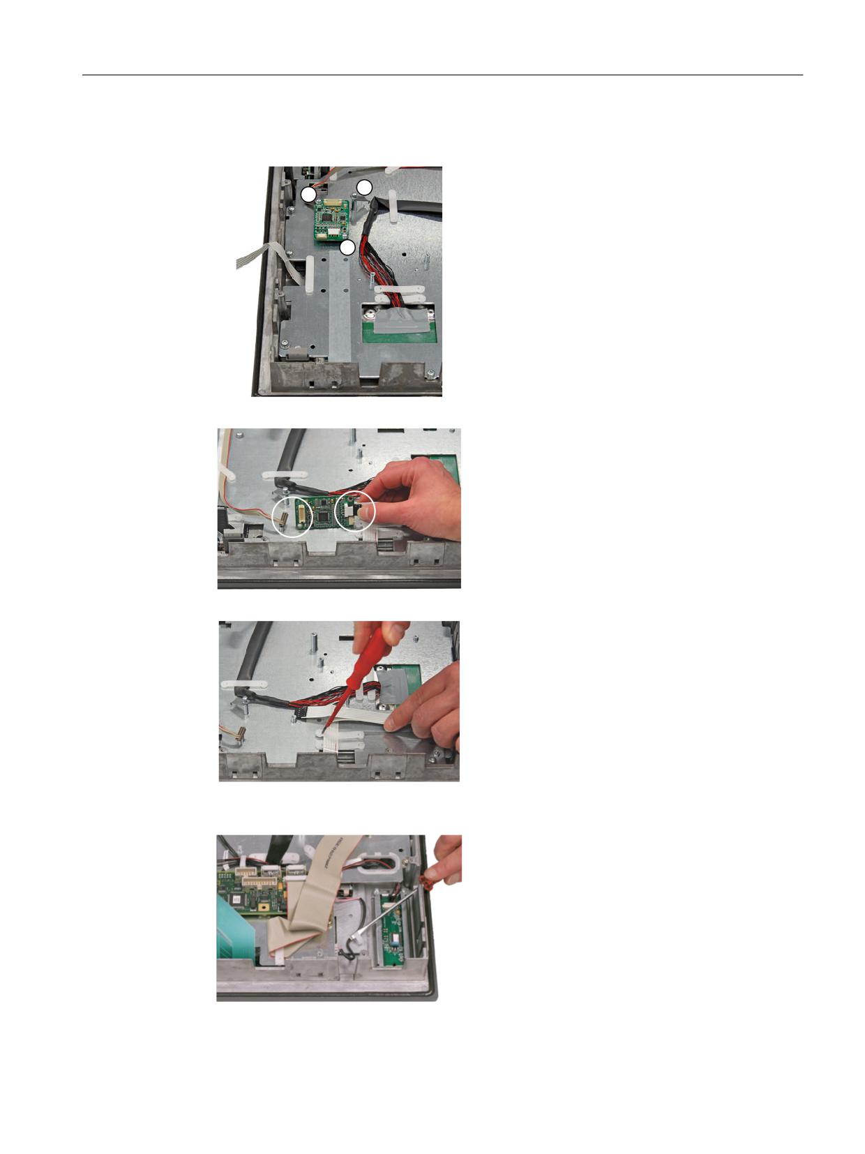
Operator panel front: TP 015A
9.6 Spare parts
Touch controller
4. Remove the three M3 screws ① that are
holding the touch controller to the display sup-
port.
Do this with a TX10 screwdriver.
5. Release the two plug connectors (left/right)
from the touch controller.
Left: Hold the connector at the upper and low-
er detent lugs, and carefully withdraw it up-
wards.
Right: Slight depress the cable clamp down-
wards and withdraw it towards the rear.
6. Release the retainer of the touch screen /
touch controller cable using a flat screwdriver.
Backlight inverter cable
7. Remove the two cables to the backlight inver-
ter (to the left and right of the display support)
by raising the clamps with a flat screwdriver
and pulling out the cables.
Operator panels
Manual, 03/2016, 6FC5397-1AP40-5BA3
141
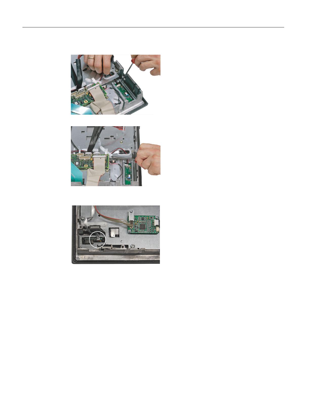
Operator panel front: TP 015A
9.6 Spare parts
Connection of keyboard controller / mouse
8. Undo the connection between the keyboard
controller and the mouse by carefully pushing
the connector back with a screwdriver.
9. Remove the retainer for the cable between
the keyboard controller and mouse.
Connection of keyboard controller / USB interface
10. Release the connection between the USB in-
terface and keyboard controller. Use a screw-
driver to push up the black terminal clamp on
the USB interface and then pull the cable out
of the holder.
Keyboard cables
Operator panels
142
Manual, 03/2016, 6FC5397-1AP40-5BA3
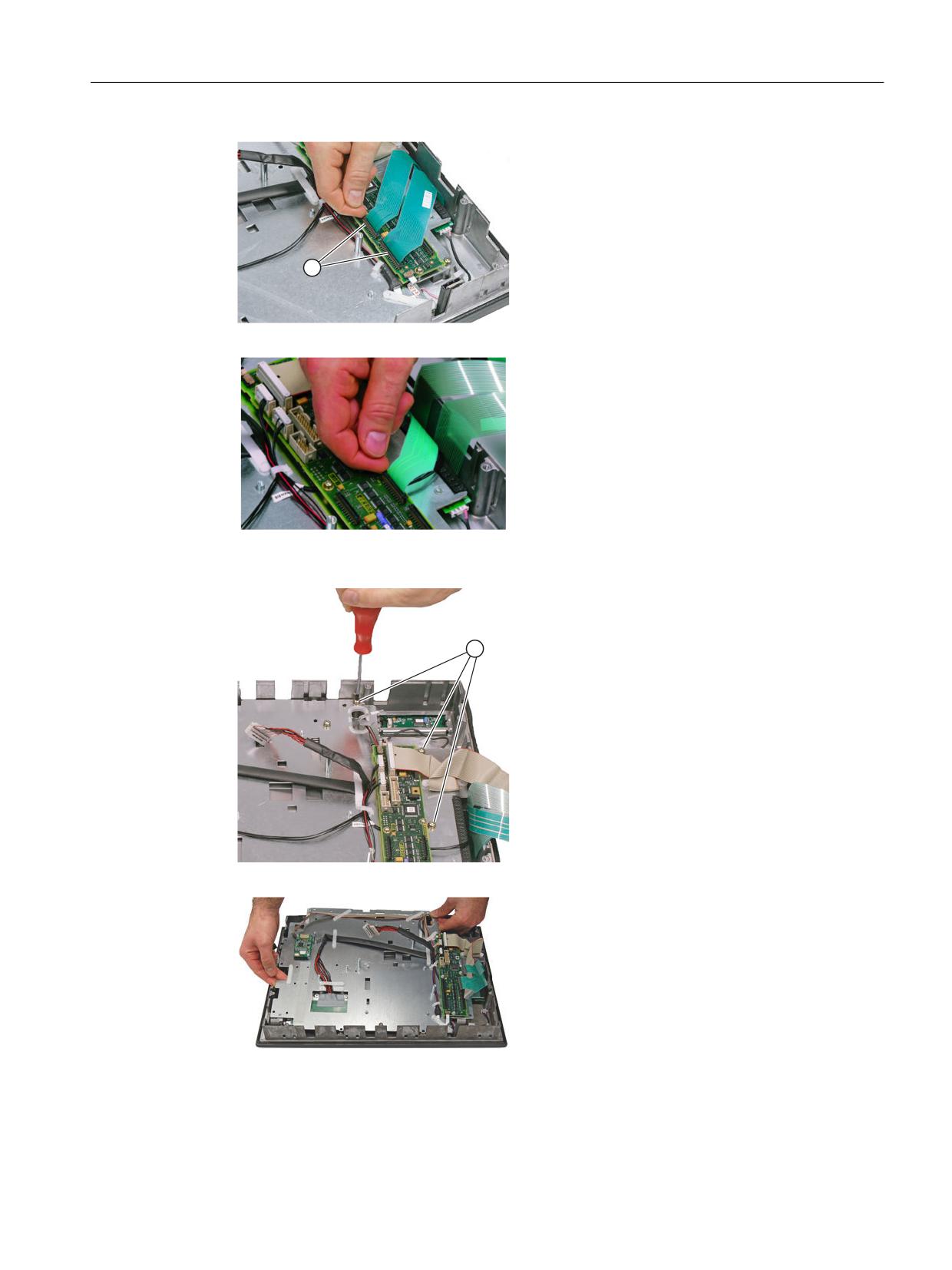
Operator panel front: TP 015A
9.6 Spare parts
11. Disconnect the 3 keyboard cables by pushing
up the terminal holders ① on the keyboard
controller and pulling the keyboard cables out
of the holder.
For detailed information about removal and
insertion of membrane connectors, see also
"General information and networking", Sec-
tion: "Connecting", Section: "Handling mem-
brane connectors".
Display support
12. Remove the twelve screws ① from the dis-
play support.
For the arrangement of the screws on the dis-
play support, refer to Figure: "TP 015A hous-
ing opened".
13. Lift off the display support.
Operator panels
Manual, 03/2016, 6FC5397-1AP40-5BA3
143
Operator panel front: TP 015A
9.6 Spare parts
14. Lay the display support down on its back to
avoid damaging the display.
USB board
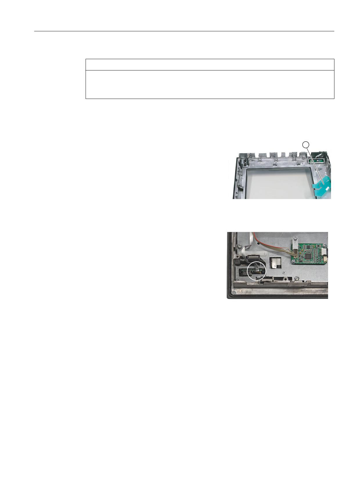
15. Remove the USB board (see diagram: "TP
015AT housing open") by releasing the 2
screws.
Mouse board
16. Loosen the four screws (M3) on the holder for
the mouse board. Lift off the holder and the
mouse board.
Installing the individual parts in the operator panel front
1. Remove the transportation locks (adhesive strip for securing cables) and the screen
protective foil from the inside.
2. Install the components in the new operator panel front in the order indicated:
Operator panels
144
Manual, 03/2016, 6FC5397-1AP40-5BA3
Operator panel front: TP 015A
9.6 Spare parts
NOTICE
Damage to the screws
Pay attention to the torques when tightening the screws (see Technical specifications
(Page 135)).
16.
Mouse board and holder
15.
USB board
14. - 12.
Display support
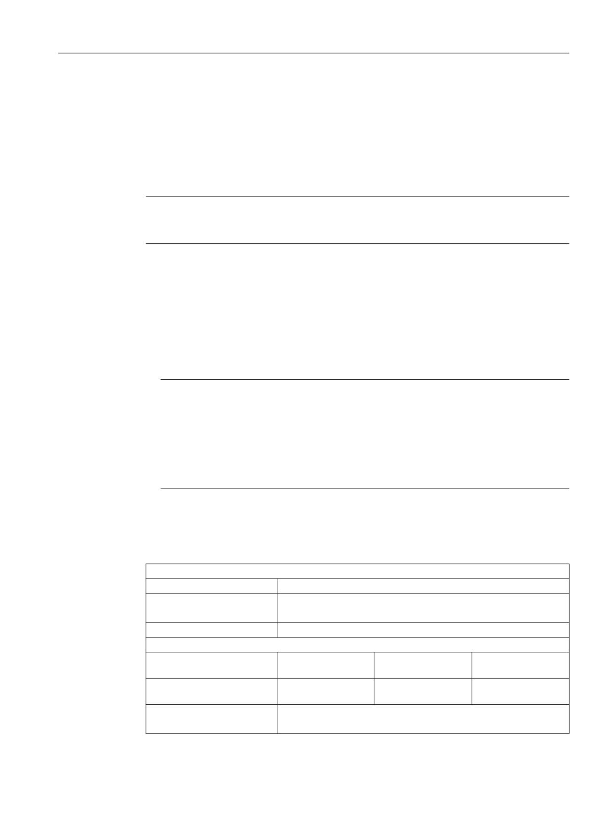
14. Bend the keyboard cables ① back
slightly before inserting the display
support
to prevent pinching and damage,
which could render them inoperable.
11.
Keyboard cables
10.
Connection of keyboard controller / USB interface
Ensure that the contact side of the
USB plug faces outwards.
9. - 8.
Connection of keyboard controller / mouse
7.
Backlight inverter cable
6. - 4.
Touch controller
3. - 1.
Cover
Operator panels
Manual, 03/2016, 6FC5397-1AP40-5BA3
145
Operator panel front: TP 015A
9.6 Spare parts
Operator panels
146
Manual, 03/2016, 6FC5397-1AP40-5BA3
Operator panel front: TP 015AT
10
10.1
Description
The SINUMERIK TP 015AT operator panel front with 15" TFT color display
and 1024 x 768 pixels (XGA) and touch screen enable the spatially distributed installation of
the operator panel front and the control. It features a membrane keyboard with 62 keys and 2
x (8 + 2) horizontal and 2 x 8 vertical softkeys and an integrated mouse.
The TP 015AT operator panel front is linked to the PCU/NCU via Ethernet as thin client in a
dedicated subnet (via DHCP server on the PCU/NCU). The distance to the operator panel
fronts is determined by the maximum distance between two network nodes / access points
(100 m). Mixed operation with several TCUs and one operator panel front directly on the PCU
is possible.
The operator panel front is secured from the rear using special clamps supplied with the panel.
Validity
This description applies to:
Type
Description
Article number
TP 015AT
Operator panel front as thin client, with touch screen
6FC5203-0AF08-1AB3
and membrane keyboard
Features
● Ethernet 10/100/1000 Mbit/s
●
4 x USB (3 x rear, 1 x front)
●
15" TFT flat screen (color) with resolution 1024 x 768 pixels
● Membrane keyboard with alphabetic, numeric, cursor, and control keypad
● Softkeys / direct keys:
-
2 x (8 + 2) horizontal rows of keys with softkey function
–
2 x 8 vertical rows of keys with softkey and direct key functions
● Shift key for switchover to the second key level (not for switching over the letters, since
they are uppercase only)
● Integrated mouse
● Status LEDs for power supply and overtemperature
● Panel cutout (W x H): 450 x 335 mm
● Degree of protection IP65 (front)
● Attachment: Tension jacks at the rear
Operator panels
Manual, 03/2016, 6FC5397-1AP40-5BA3
147
Operator panel front: TP 015AT
10.2 Operator controls and indicators
10.2
Operator controls and indicators
10.2.1
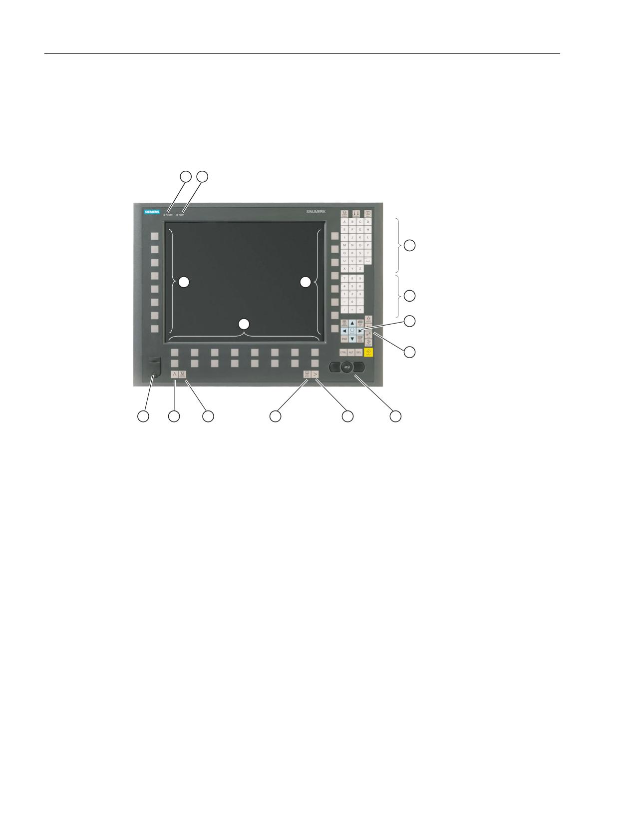
View
① Status LED: POWER
② Status LED: TEMP
(illuminated LEDs indicate increased wear)
③ Softkeys and direct keys
④ Alphabetic key group
⑤ Numeric key group
⑥ Cursor key group
⑦ Control key group
⑧ Mouse
⑨ Menu forward key
⑩ Menu select key
⑪ Softkeys
⑫ Machine area key
⑬ Menu back key
⑭ Front USB interface
Image 10-1 Front view of the TP 015AT operator panel front
Operator panels
148
Manual, 03/2016, 6FC5397-1AP40-5BA3
Operator panel front: TP 015AT
10.2 Operator controls and indicators
10.2.2
Operation
The operator panel front is operated by
● using the touch screen to select the application-specific functions, e.g. by touching one of
the displayed buttons.
● Softkeys
● Keys
● Mouse
NOTICE
Damage to the operator controls
Do not touch the operating elements with pointed or hard objects. This may considerably
reduce their service lives.
10.2.3
Keyboard
Keyboard
Several keys and keypads are installed on the operator panel front:
● The alphabetic block contains the letters A - Z and the space character.
● The numeric block contains the digits 0 - 9, and the characters "-", "/", "=", "+" and ".".
● The cursor key group is used to navigate on the screen.
● The control key group includes special functions.
● The mouse comprises the center actuation field (corresponds to the function of a tracker
ball) and two keys for the left and right mouse key.
● The softkeys call up functions that are available on the screen via a menu bar.
● The menu select key displays the area menu.
● The menu forward key enables an expansion of the horizontal softkey bar in the same menu.
● The machine area key switches directly into the "Machine" operating area.
● The menu back key returns to the higher-level menu, one window is closed.
Switching between upper and lower case
To toggle between upper and lower case letters, press the key combination Ctrl + Shift
Upper case is always activated as standard.
Operator panels
Manual, 03/2016, 6FC5397-1AP40-5BA3
149
Operator panel front: TP 015AT
10.2 Operator controls and indicators
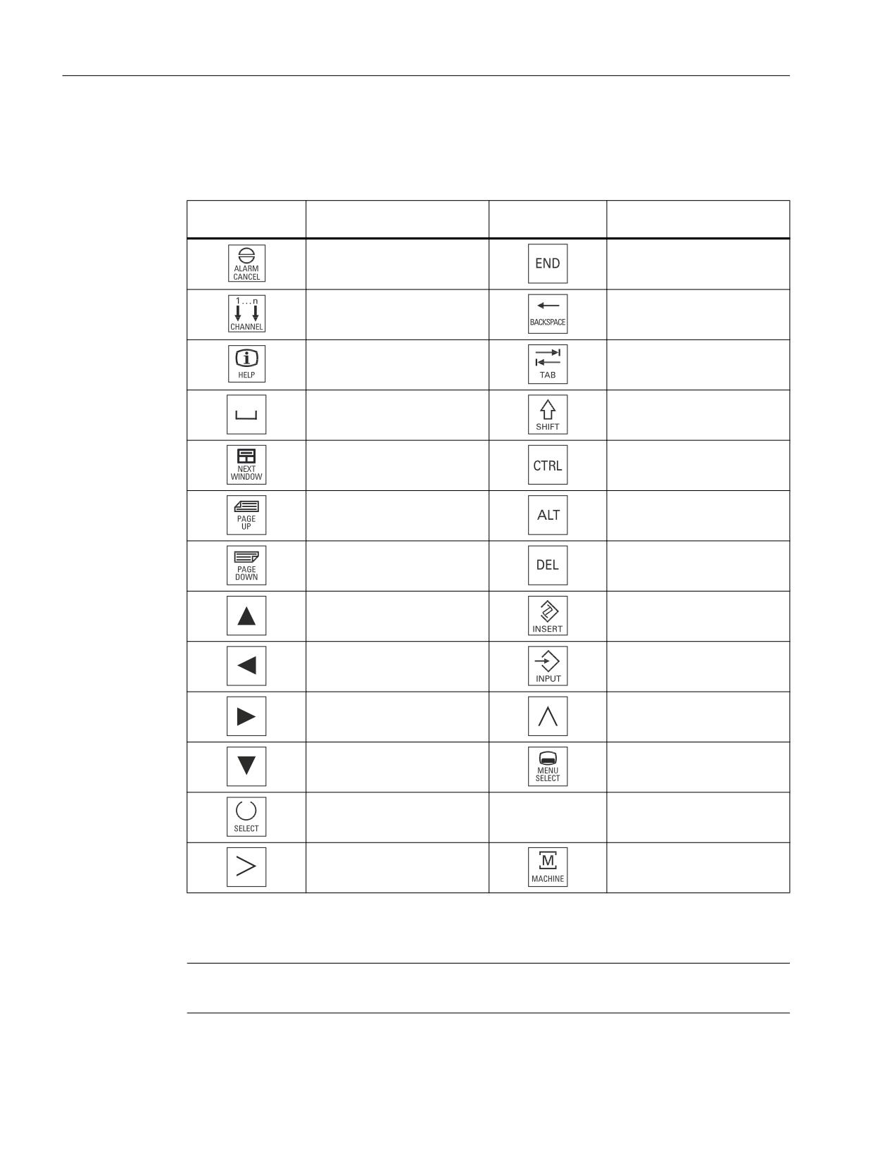
Overview of the key symbols
The key symbols used on the operator panel front are shown below along with the
corresponding function keys on the PC keyboard.
Key
Function corresponds to the
Key
Function corresponds to the
PC key function
PC key function
Esc
End
F11
Backspace
F12
Tab
Space
(only intended for internal key-
board changeover)
Home
Ctrl key
Page up
Alt key
Page down
Delete
Cursor up
Insert
Cursor left
Enter
Cursor right
F9
Cursor down
F10
5 (in numeric key group)
A, ..., Z
<Shift> A, ..., Z
<Shift> F9
<Shift> F10
Display
Note
Pixel error according to DIN EN ISO 13406-2 Class II.
Operator panels
150
Manual, 03/2016, 6FC5397-1AP40-5BA3

Operator panel front: TP 015AT
10.3 Interfaces
10.2.4
Screen saver
If a screen with high contrast is displayed unchanged for longer than an hour, then the
screensaver must be activated in order to protect the TFT display against so-called "burning
in" of the last displayed screen.
The time can be adapted individually. Further information can be found at:
Commissioning of Basic Software and Operating Software, SINUMERIK Operate (IM9)
10.3
Interfaces
The TP 015AT operator panel front has the following interfaces:
Function
Designation
Type
Ethernet interface
X202
8-pin RJ45 socket
Double USB interface
X203 / X204
USB 2.0 Hi-Speed socket A
USB interface
X213
USB 2.0 Hi-Speed socket A
24 VDC power supply
X206
3-pin terminal block
Front USB interface
-
USB 1.1 Full Speed socket A
Operator panels
Manual, 03/2016, 6FC5397-1AP40-5BA3
151
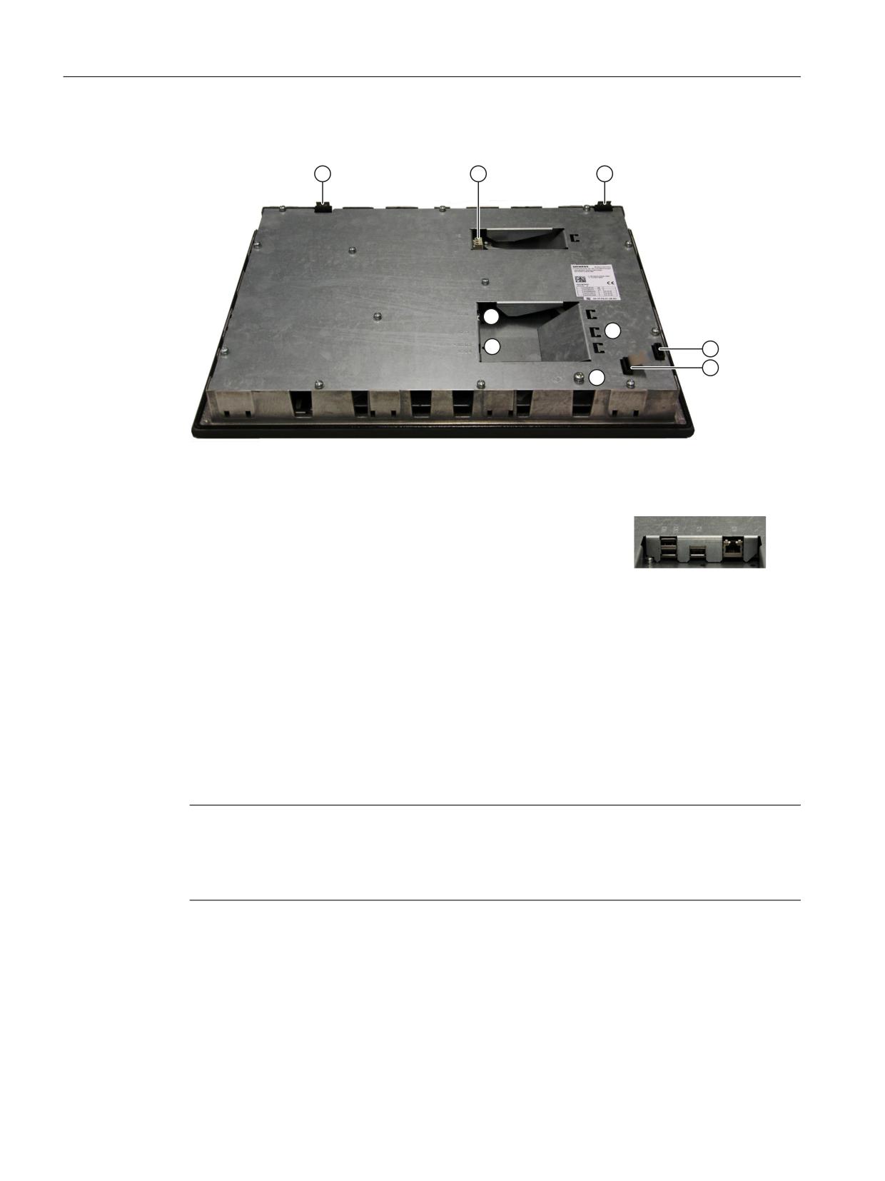
Operator panel front: TP 015AT
10.3 Interfaces
Rear
3(
9
9
① Teil 1
Slide-in labels for vertical softkeys (see Chpater Spare parts)
② X206
Power supply (with connector that can be screwed in place)
③ Teil 2
Slide-in labels for vertical softkeys (see Chpater Spare parts)
④
X202
Ethernet interface
;
;
;
;
⑤ X203/X204/
USB interfaces
X213
⑥
-
Strain relief for connecting cables
⑦ Teil 3
Slide-in labels for horizontal softkeys (for these, there is no foil as template)
⑧ Teil 4
⑨
-
M5 grounding screw (for screw connection with cable lug)
Image 10-2 TP 015AT - Rear with interfaces
Front
USB 1.1 Full Speed for connecting an external keyboard, mouse or USB flash drive (see Image
10-1 Front view of the TP 015AT operator panel front (Page 148)).
Note
Note that the electromagnetic compatibility of commercially available peripheral devices
operated via the USB interface is usually rated for office use only.
For industrial use, components with a higher degree of certification are recommended.
Pin assignment
The pin assignment of the interfaces, see "General information and networking" →
"Connecting".
Operator panels
152
Manual, 03/2016, 6FC5397-1AP40-5BA3
Operator panel front: TP 015AT
10.4 Installation
10.4
Installation
10.4.1
Mounting
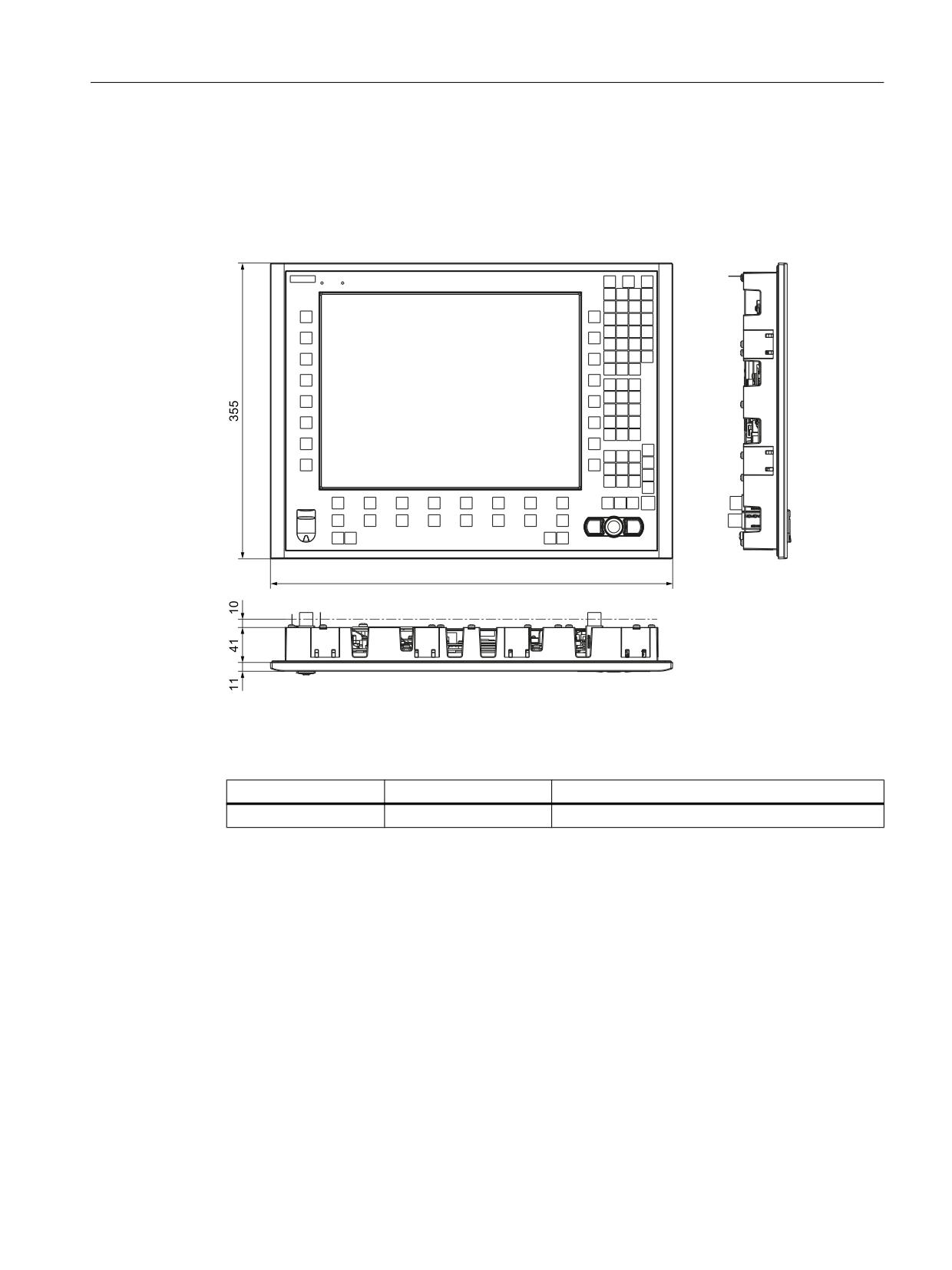
Image 10-3 TP 015AT with TCU (integrated)
Table 10-1
Dimensions of the mounting opening
Width (mm)
Height (mm)
Mounting depth + clearance (mm)
450
335
42 + 10
Thanks to the tension jacks on the TP 015AT, drill-holes or screw holes are not needed.
This retaining method also enables the IP65 degree of protection (but only in conjunction with
a circumferential seal and when the protective USB cap is fitted).
Operator panels
Manual, 03/2016, 6FC5397-1AP40-5BA3
153
Operator panel front: TP 015AT
10.4 Installation
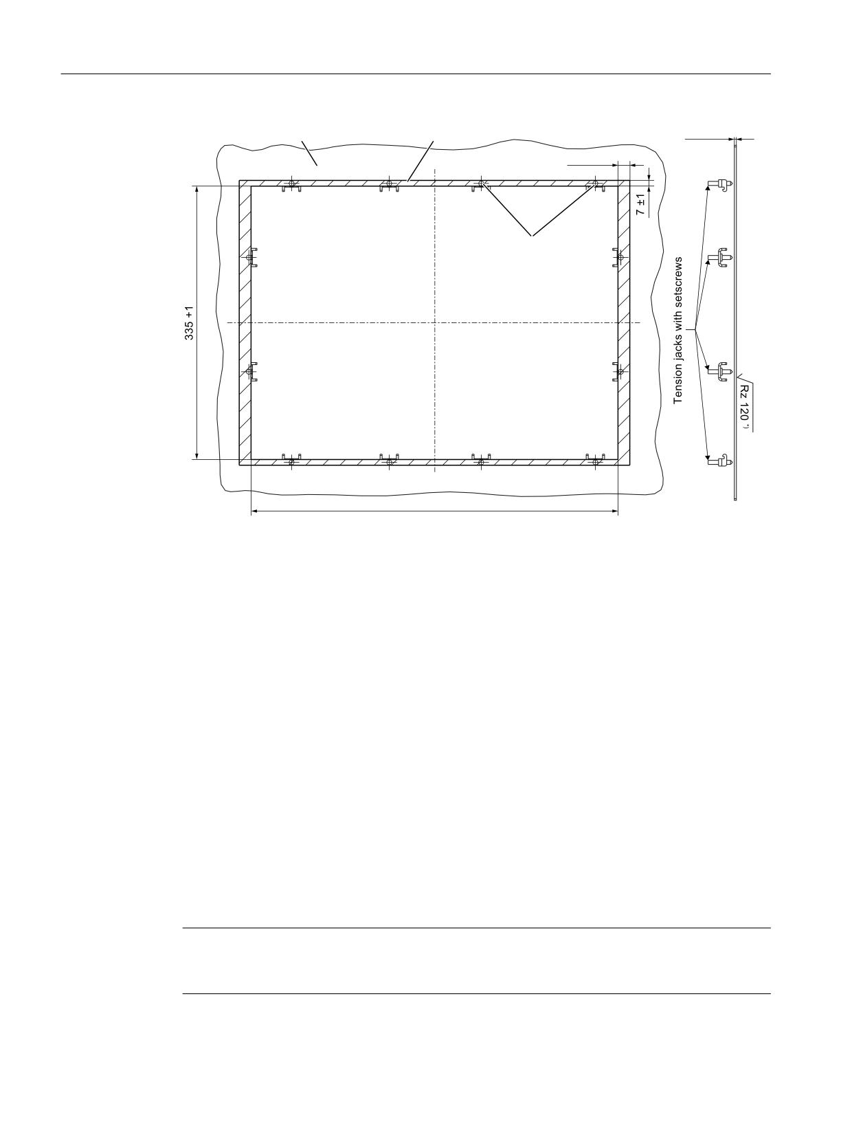
0RXQWLQJ SDQHO
6HDOLQJ DUHD
s
3UHVVXUH SRLQWV IRU
WHQVLRQ MDFNV
,Q WKH VHDOLQJ DUHD
Image 10-4 Dimension sheet for installing the TP 015AT operator panel front
10.4.2
Touchscreen calibration
Whenever a new operator panel front is connected the touchscreen must be calibrated.
Procedure
For a description of the calibration, refer to Chapter Touchscreen calibration (Page 249).
10.4.3
Softkey labeling
User-specific functions can be assigned to the horizontal and vertical softkey bars. Printed
labeling strips can be used to label the softkeys.
Blank labels are already installed on delivery.
To make the vertical labels, DIN A4 foils are available (see Chapter, "Spare parts"
→Overview (Page 156) ).
Note
Use the "Arial" font to format text. This font is comparable to the "Univers S57" font, used by
Siemens for the key labeling.
Operator panels
154
Manual, 03/2016, 6FC5397-1AP40-5BA3
Operator panel front: TP 015AT
10.5 Technical data
Procedure
1. Letter the matt side of the foil using a laser printer.
2. Cut the printed labels along the preprinted lines.
3. Insert the strips into the slots provided on the rear side of the operator front panel (see
Image 10-2 TP 015AT - Rear with interfaces (Page 152)).
10.5
Technical data
Safety
Safety class
III; PELV according to EN 50178
Degree of protection accord-
Front side: IP65
ing to EN 60529
Rear side: IP00
Approvals
CE / cULus
Electrical data
Power supply
24 VDC
Current consumption
Typical, approx. 1.0 A
Max. approx. 2.5 A
Power consumption
Typical, approx. 24 W
Max. approx. 50 W
Mechanical data
Dimensions
Width: 483 mm
Height: 355 mm
Depth: 53 mm
Weight
Approx. 7.6 kg
Tightening torques, max.
Tension jack screws:
M3 screws:
M4 screws:
0.5 Nm
0.8 Nm
1.8 Nm
M5 grounding screw: 3 Nm
Display
Size / resolution
15" TFT / 1024 x 768 pixels
MTBF backlight
Typ. 50,000 h at 25º C (dependent on the temperature)
Note
Information about the climatic and mechanical environmental conditions is contained in the
associated section under:
"General notes and interconnection" → "Operational planning".
Operator panels
Manual, 03/2016, 6FC5397-1AP40-5BA3
155
Operator panel front: TP 015AT
10.6 Replacement parts
10.6
Replacement parts
10.6.1
Overview
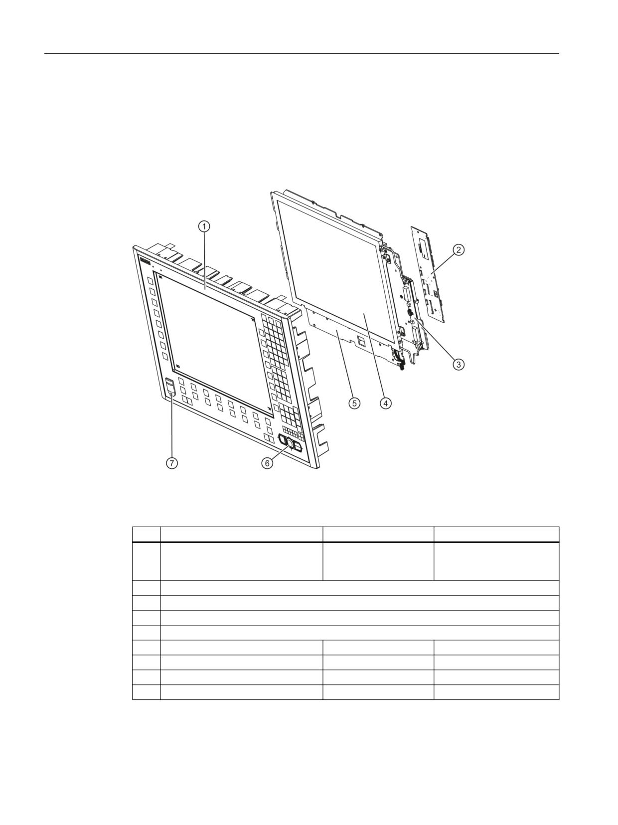
The diagram shows the TP 015AT operator panel front disassembled into its individual parts.
Image 10-5 Individual parts for the TP 015AT operator panel front
The components listed in the following table with an article number are available as spare parts.
Spare part
Article number
Remark
①
Operator panel front
A5E01136461
Without LCD unit, mouse,
USB port and keyboard con-
troller
②
Keyboard controller
③
Background lighting with backlight inverter
④
LCD unit
⑤
Display support
⑥
Mouse
6FC5247-0AF01-0AA0
⑦
USB caps
6FC5248-0AF05-0AA0
Set of 10
Tension jacks
6FC5248-0AF14-0AA0
Set of 9
Slide-in strips that can be labeled
6FC5248-0AF24-0AA0
Set with 3 foils, DIN A4
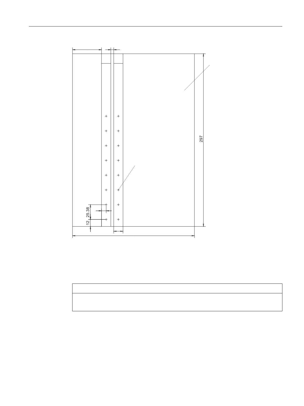
The dimensions for creating slide-in labels from the foil for labeling the vertical softkeys can
be seen in the following diagram.
Operator panels
156
Manual, 03/2016, 6FC5397-1AP40-5BA3
Operator panel front: TP 015AT
10.6 Replacement parts
3DUW
3DUW
)LOP ',1 $
&HQWHU RI WKH NH\
Image 10-6 Dimensions for slide-in labels
10.6.2
Replacement
NOTICE
Damage to sensitive components due to static electricity
Spare parts must always be replaced by properly trained personnel!
USB cap / tension jack
The replacement of the USB sealing cap and tension jacks will not be described since it is
simple and self-explanatory.
Operator panels
Manual, 03/2016, 6FC5397-1AP40-5BA3
157
Operator panel front: TP 015AT
10.6 Replacement parts
Operator panel front
When the operator panel front is replaced, the display, keyboard controller, touch controller,
mouse and USB interface can be used again. They are therefore disassembled and re-
assembled after the appropriate component has been replaced.
Note
We recommend reusing the keypad controller to prevent any loss of the control parameters
that have been programmed in.
Dismounting individual parts from the operator panel front
1
1
1
1
1
1
2
1
1
1
1
1
1
1
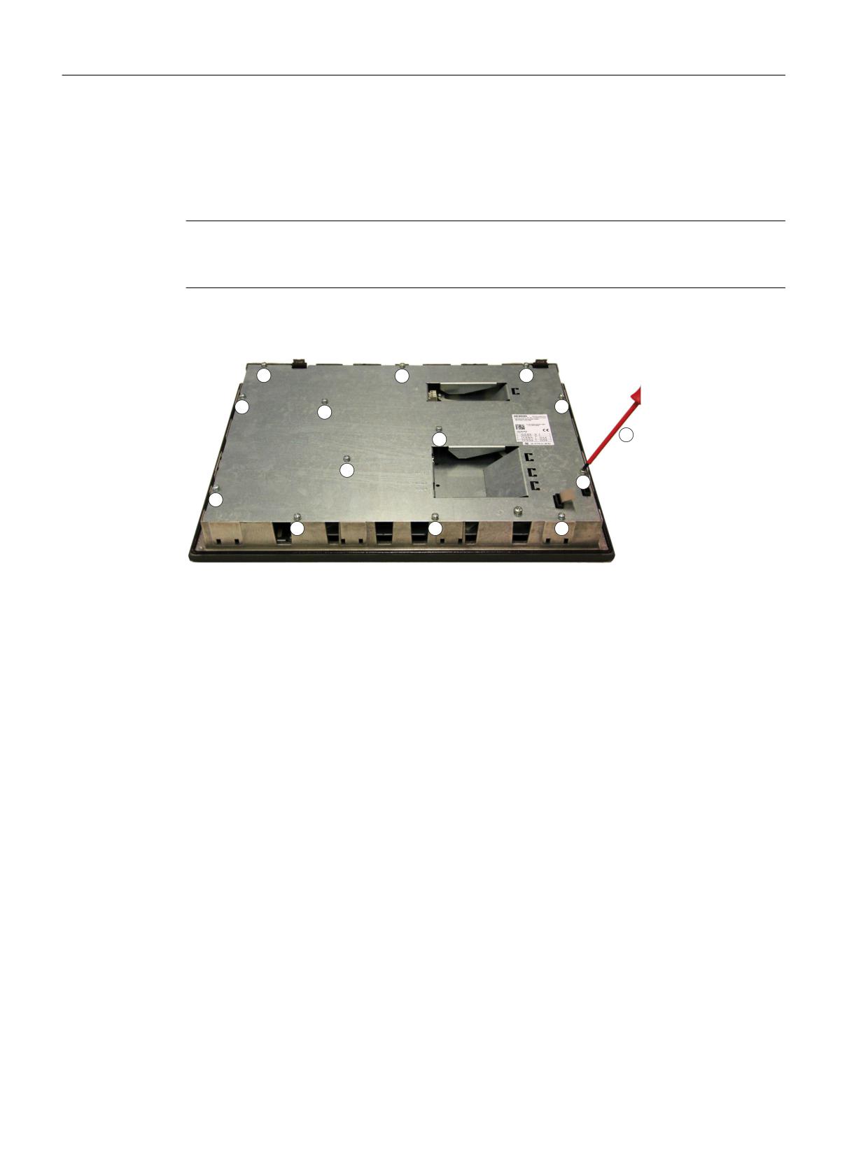
1. Place the TP 015AT on a soft horizontal surface. Loosen the 13 housing screws (M4)
① using a Torx screwdriver T25 ②.
2. Remove the cover.
Operator panels
158
Manual, 03/2016, 6FC5397-1AP40-5BA3
Operator panel front: TP 015AT
10.6 Replacement parts
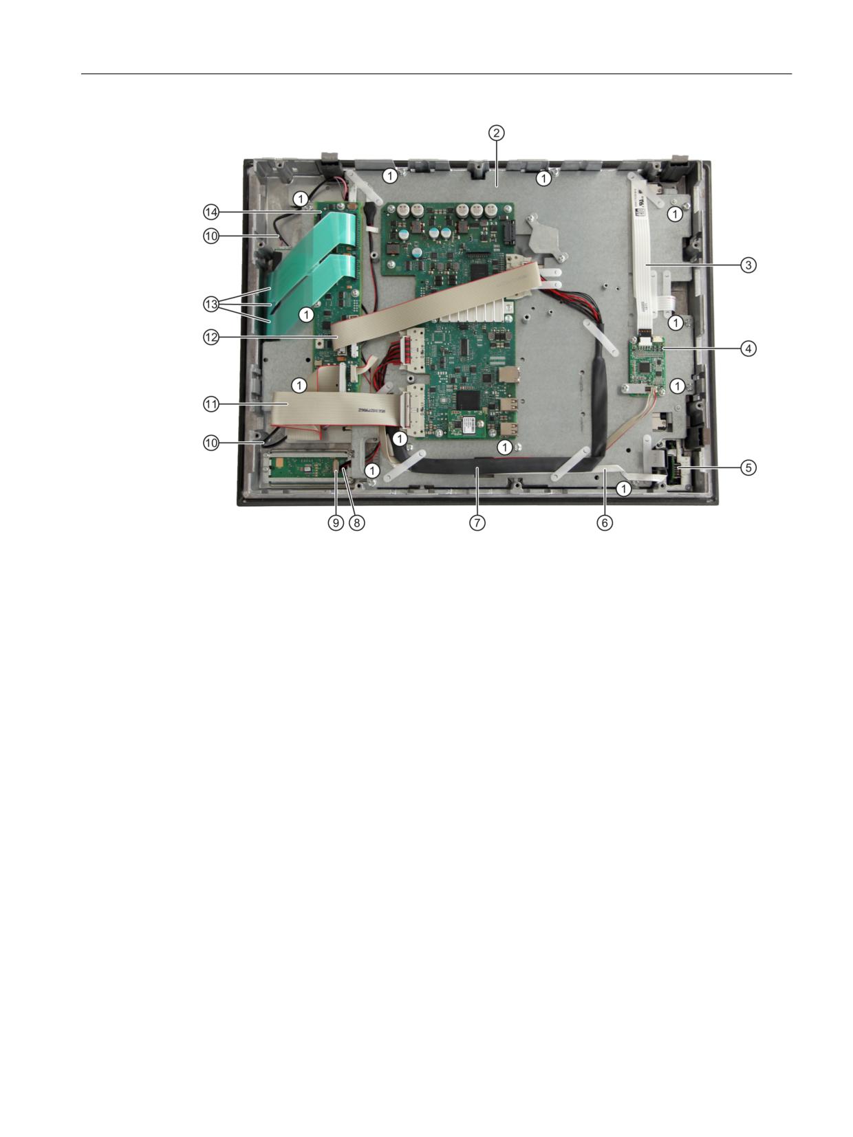
① Screws (M4) for display support
② Display support
③ Cable of the touch controller
④ Touch controller
⑤ USB interface
⑥ Ribbon cable for keyboard controller / USB interface
⑦ Display cable
⑧ Cable, mouse / keyboard controller
⑨ Connector, mouse interface
⑩ Backlight inverter cable
⑪ I/O USB cable
⑫ Direct key cable
⑬ Keyboard cables
⑭ Keyboard controller
Image 10-7 TP015AT housing opened
Operator panels
Manual, 03/2016, 6FC5397-1AP40-5BA3
159
Operator panel front: TP 015AT
10.6 Replacement parts
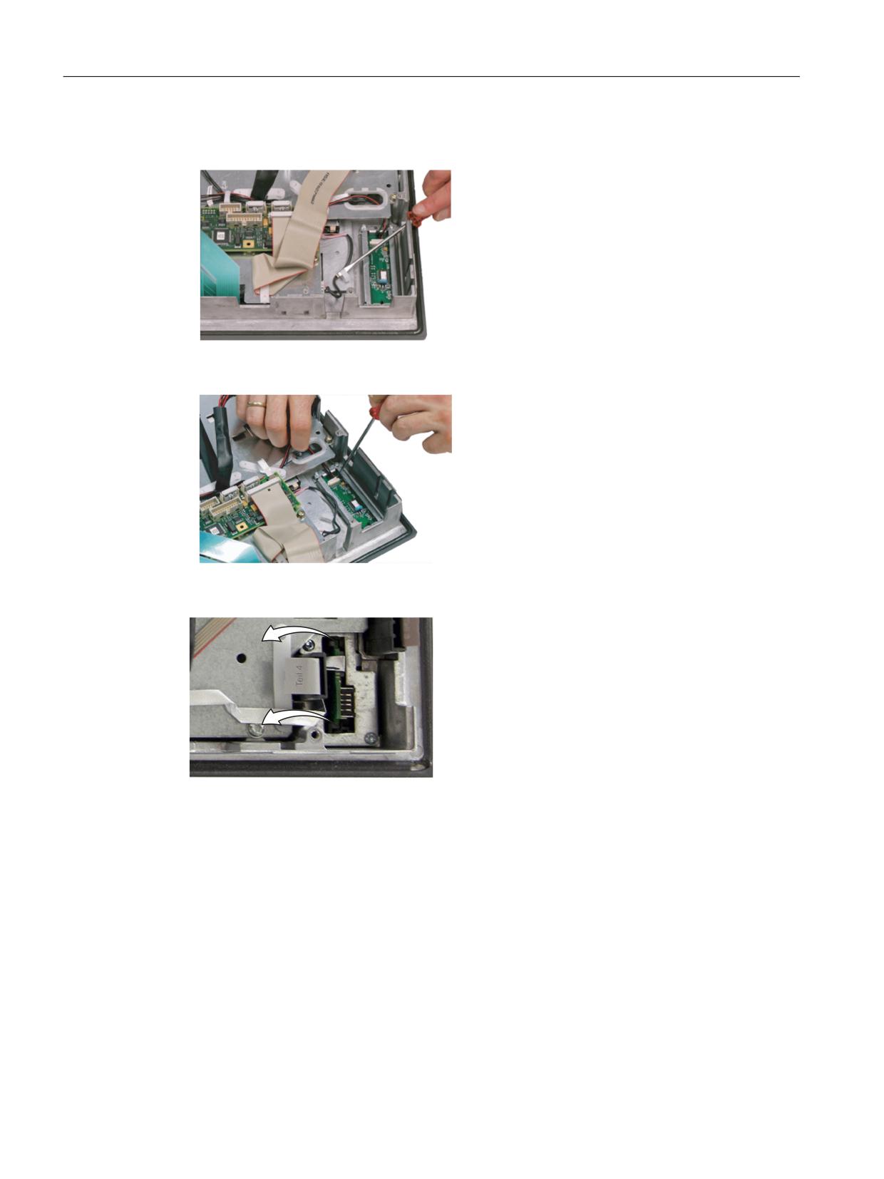
Cables, backlight inverter
3. Remove the two cables to the backlight inver-
ter (to the left and right of the display support)
by raising the clips with a flat screwdriver and
pulling out the cables.
Connection of keyboard controller / mouse
4. Undo the connection between the keyboard
controller and the mouse by carefully pushing
the connector back with a screwdriver.
USB board
5. Release the connection to the keyboard con-
troller by releasing both retaining clamps next
to the USB board and withdrawing them.
Do not remove the cable from the board!
Keyboard cables
Operator panels
160
Manual, 03/2016, 6FC5397-1AP40-5BA3
Operator panel front: TP 015AT
10.6 Replacement parts
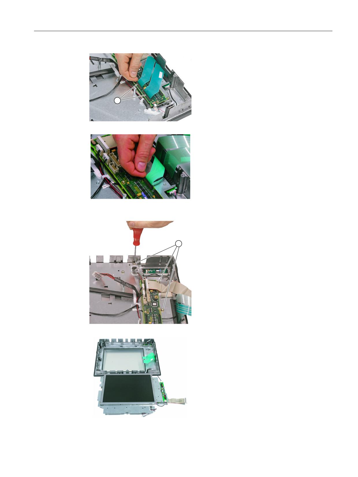
6. Disconnect the 3 keyboard cables by pushing
up the terminal holders ① on the keyboard
controller and pulling the keyboard cables out
of the holder.
For detailed information about removal and
insertion of membrane connectors, see also
"General information and networking", Chap-
ter: "Connecting", Section: "Handling mem-
brane connectors".
Display support
7. Remove the 12 screws ① from the display
support and lift it off.
For details of how the screws are arranged on
the display support, refer to Figure: "TP
015AT housing opened".
8. Lift off the display support.
9. Lay the display support down on its back to
avoid damaging the display.
Operator panels
Manual, 03/2016, 6FC5397-1AP40-5BA3
161
Operator panel front: TP 015AT
10.6 Replacement parts
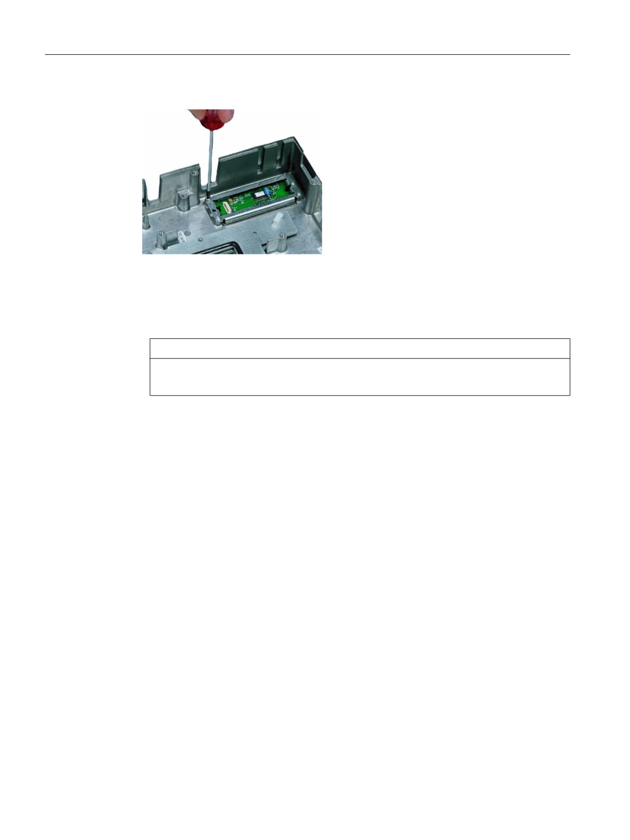
Mouse board
10. Loosen the 4 screws (M3) on the holder for
the mouse board. Lift off both the holder and
the mouse board.
Installing the individual parts in the operator panel front
1. Remove the transportation safety precautions (adhesive strip for securing cables) and the
screen protective foil from the inside.
2. Install the components in the new operator panel front in the order indicated:
NOTICE
Damage to the screws
Pay attention to the torques when tightening the screws (see Technical data (Page 155)).
2.1 Mouse board and holder
2.2 Display support
Slightly bend the keyboard cables to the rear before installing the display carrier.
Otherwise, they could jam or be damaged and therefore no longer function.
2.3 USB board
Press the USB board into place until you hear it lock into the retaining clamps.
2.4 Keyboard cables
2.5 Connection of keyboard controller / mouse
2.6 Cables, backlight inverter
2.7 Cover
Operator panels
162
Manual, 03/2016, 6FC5397-1AP40-5BA3
Operator panel front: OP 015 black
11
11.1
Description
The SINUMERIK OP 015 black operator panel front has a touch-sensitive glass surface with
multiple finger operator control. The integrated TCU enables the operator panel front and
control to be installed separately.
The OP 015 black operator panel front is linked to the PCU/NCU via Ethernet as thin client in
a dedicated subnet (via DHCP server on the PCU/NCU). The distance to the operator panel
fronts is determined by the maximum distance between two network nodes / access points
(100 m). Mixed operation with several TCUs and one operator panel front directly on the PCU
is possible.
The operator panel front is secured from the rear using special clamps supplied with the panel.
Validity
This description applies to:
Type
Description
Article number
OP 015 black
Operator panel front as thin client with touch screen
6FC5303-0AF14-0AA0
Features
● Ethernet 10/100/1000 Mbit/s
●
3 x USB (max. high speed) on the rear
●
15" LCD flat screen (color) in widescreen format
● Multiple finger operation in the screen area
● Printed keyboard with alphabetic, numeric, cursor and control keypad
● Status LEDs for power supply, key feedback and keylock / Caps lock key
● Panel cutout (W x H): 450 x 290 mm
● Can be installed by one person (see Section "Mounting")
● Degree of protection: IP65 / IP66
● Attachment: Tension jacks at the rear
- Min./max. thickness of the wall 1.5 to 6 mm
Operator panels
Manual, 03/2016, 6FC5397-1AP40-5BA3
163
Operator panel front: OP 015 black
11.2 Operator control and display elements
Note
Connecting USB devices
The OP 015 black does not have any USB interfaces on the front. If required, the rear USB
interfaces can be routed to the front via a USB extension (see Section "Keyboards and
additional components").
11.2
Operator control and display elements
11.2.1
View
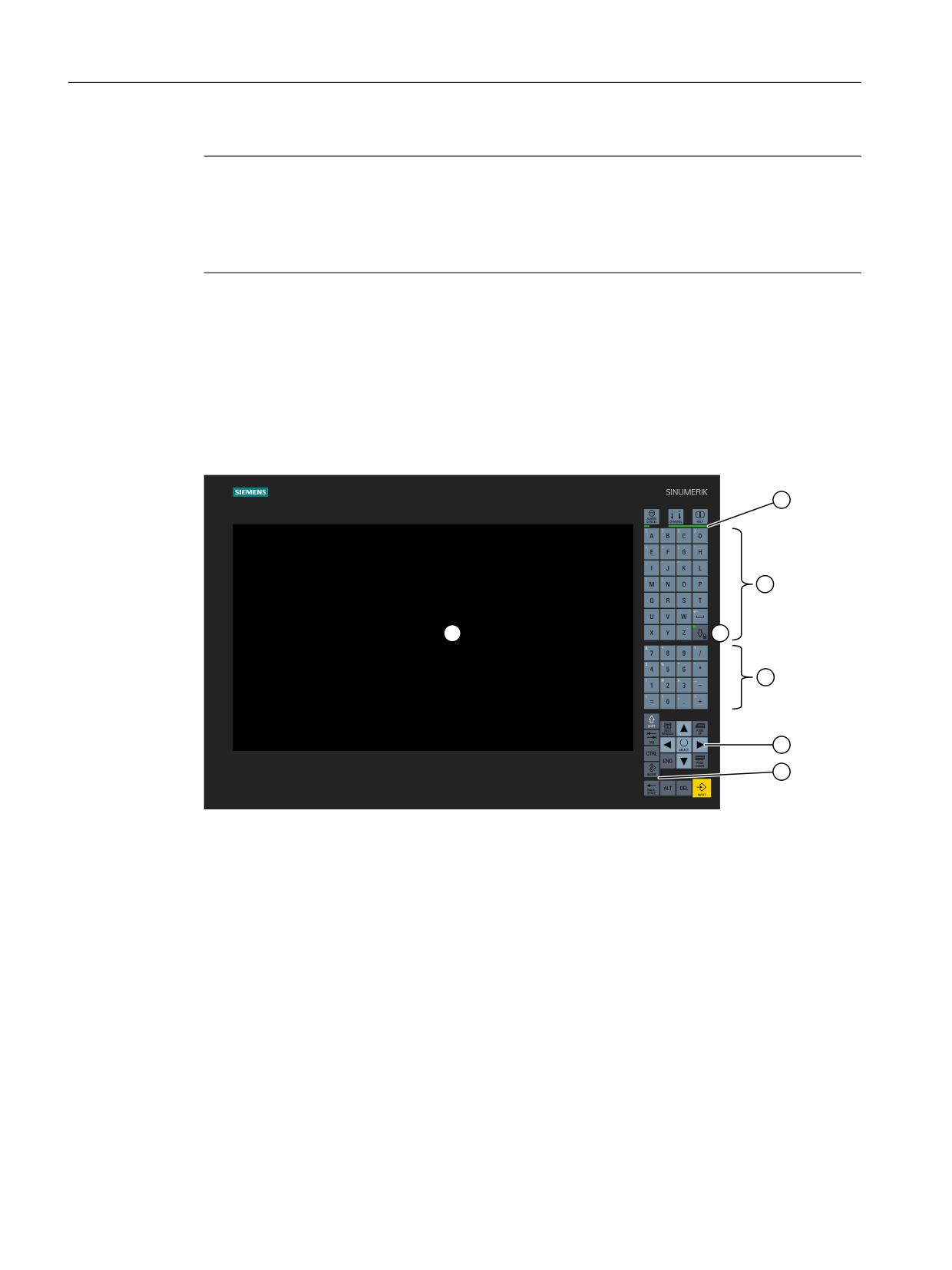
① Multiple finger operating area for operating software (softkeys) in the display area
② Green LED bars for POWER OK (left) and key feedback (right)
③ Alphabetic key group
④ Caps lock key incl.keylock - green LED (displays keylock active or Caps lock key)
⑤ Numeric key group
⑥ Cursor key group
⑦ Control key group
Image 11-1 Front view of the OP 015 black operator panel front
Operator panels
164
Manual, 03/2016, 6FC5397-1AP40-5BA3
Operator panel front: OP 015 black
11.2 Operator control and display elements
11.2.2
Operation
The operator panel front is operated through finger contact with the touch-sensitive glass
surface:
● Depending on the application-specific functions shown in the display area, for example, by:
- pressing a softkey or a displayed button
- gestures with up to eight fingers
● Depending on the displayed keys. Two keys (plus modifier keys) can be pressed
simultaneously.
- Modifier: CTRL, ALT, SHIFT
Note
Notes regarding operation of the touch-sensitive glass surface with multi-finger operation
function using gestures.
Observe the following notes in order to avoid incorrect operation of the touch-sensitive glass
surface with multi-finger operation function. Otherwise, entries made at the device will either
be incorrectly identified/implemented - or not at all.
● The OP 015 black does not support safety-relevant functions and these may also not be
implemented in the touch-sensitive glass surface.
● The touch-sensitive glass surface reacts to contact with its surface, not to pressure.
Therefore, do not attach a protective film subsequently to the touch-sensitive glass surface.
Also remove all protective and packaging films, as these have a negative impact/prevent
data from being entered and initiate incorrect operator entries.
● Only operate the touch-sensitive glass surface with your finger tips, not with your fingernails.
● Touch the touch-sensitive glass surface either perpendicularly or at a maximum angle of
45° to the surface.
● Avoid unintentional multiple contact, e.g. with the knuckles or by leaning against the display.
● Make sure that the surface of the touch-sensitive glass screen does not get dirty. Cleaning
information can be found on the Internet in the following article in the Service & Support
portal of Siemens Industry:
Constantly check whether the operator actions are recognized by the device.
Note
Please observe the valid C standards for the particular machine type (e.g. for turning machines:
EN ISO 23125-2010, pages 36 and 49). These state that a button that initiates motion with the
protective door open must be implemented using an additional acknowledgment device; this
is because for single-channel keyboards - such as the OP 015 black - generally no PL
(performance level) "d" can be achieved.
Operator panels
Manual, 03/2016, 6FC5397-1AP40-5BA3
165
Operator panel front: OP 015 black
11.2 Operator control and display elements
Displaying the TCU menu
To display the TCU menu, simultaneously touch the left-hand and right-hand lower corner of
the active display area in order to display the TCU menu.
If you have connected a USB PC keyboard to the OP 015 black, you can also display the TCU
menu by simultaneously pressing keys F9 and F10.
Gloves
Do not wear thick gloves, such as work gloves, when operating the touch-sensitive glass
surface. You can wear thin gloves made of cotton or gloves for touch-sensitive glass surfaces
with capacitive touch function.
You can wear the following gloves for operating the touch-sensitive glass user interface of the
operator panel:
● Dermatril L
● Camatril Velours Art. 730
● Uvex Profas Profi ENB 20A
● Comasec PU 900 (4342)
● Camapur Comfort Art. 619
● KCL Men at Work Art. 301
● Carex Art. 1505/k (leather)
● Cotton Cat. 1
Note
The gloves listed here are recommendations only. The type designations can change.
Keylock
E.g. it is advisable to use the keylock when cleaning the device:
● Activate the keylock by pressing the Caps lock key for at least five seconds, the LED flashes.
● Deactivate the keylock by pressing the Caps lock key again for at least five seconds.
The keylock can also be triggered by the software.
Note
The keylock only applies to the keys next to the display and not for the display touch.
Operator panels
166
Manual, 03/2016, 6FC5397-1AP40-5BA3
Operator panel front: OP 015 black
11.2 Operator control and display elements
11.2.3
Keyboard
Keyboard
Several keys and keypads are installed on the operator panel front:
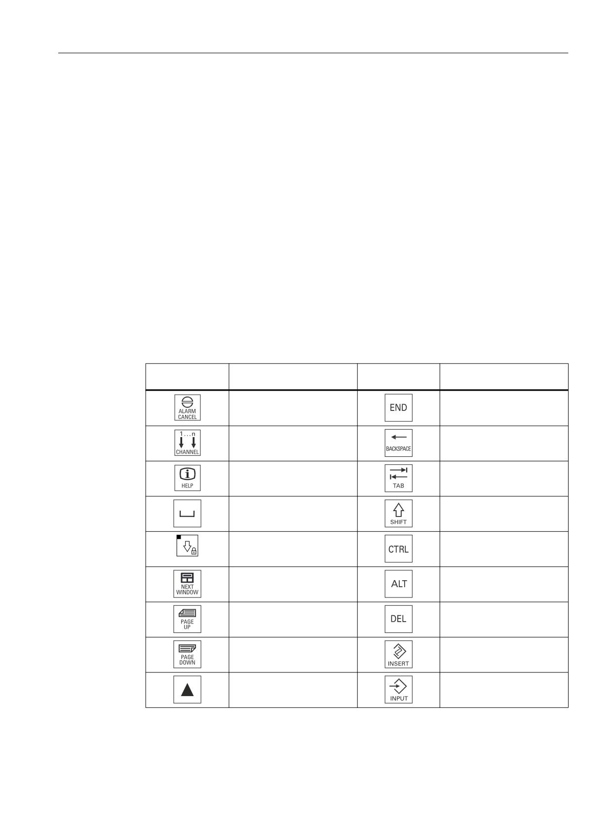
● The alphabetic block contains the letters A - Z, the space character and the Caps lock key
with keylock.
● The numeric block contains the digits 0 - 9, and the characters "/", "*", "-", "+", "=" and ".".
● The cursor key group is used to navigate on the screen.
● The control key group includes special functions.
Switching between upper and lower case
Upper case is always activated as standard. To toggle between upper and lower case letters,
press the Caps lock key.
Overview of the key symbols
The key symbols used on the operator panel front are shown below along with the
corresponding function keys on the PC keyboard.
Key
Function corresponds to the
Key
Function corresponds to the
PC key function
PC key function
Esc
End
F11
Backspace
F12
Tab
Space
(only intended for internal key-
board changeover)
Caps lock
Ctrl key
Home
Alt key
Page up
Delete
Page down
Insert
Cursor up
Enter
Operator panels
Manual, 03/2016, 6FC5397-1AP40-5BA3
167
Operator panel front: OP 015 black
11.3 Interfaces
Key
Function corresponds to the
Key
Function corresponds to the
PC key function
PC key function
Cursor left
5 (in numeric key group)
Cursor right
A, ..., Z
<Shift> A, ..., Z
Cursor down
Display
Pixel error according to DIN EN ISO 9241-307, Error class II.
11.2.4
Screen saver
If an image with high contrast is displayed without change for longer than one hour, the dark-
ON function must be activated for energy efficiency reasons.
The time can be adapted individually. Further information can be found at:
Commissioning of Basic Software and Operating Software, SINUMERIK Operate (IM9)
11.3
Interfaces
The OP 015 black operator panel front has the following interfaces:
Interface name
Connector
Speed
Permissible to-
Connector type
name
tal length
Ethernet interface
X202
1000 Mbps
Max. 100 m
8-pin RJ45 socket
Double USB interface 1
X203, X204
480 Mbps each
Max. 1.8 m
Double USB socket
24 V power supply
X206
-
Max. 10 m
3-pin Combicon con-
nector
USB interface 2
X213
480 Mbps
Max. 1.8 m
Single USB socket
Operator panels
168
Manual, 03/2016, 6FC5397-1AP40-5BA3
Operator panel front: OP 015 black
11.3 Interfaces
Rear
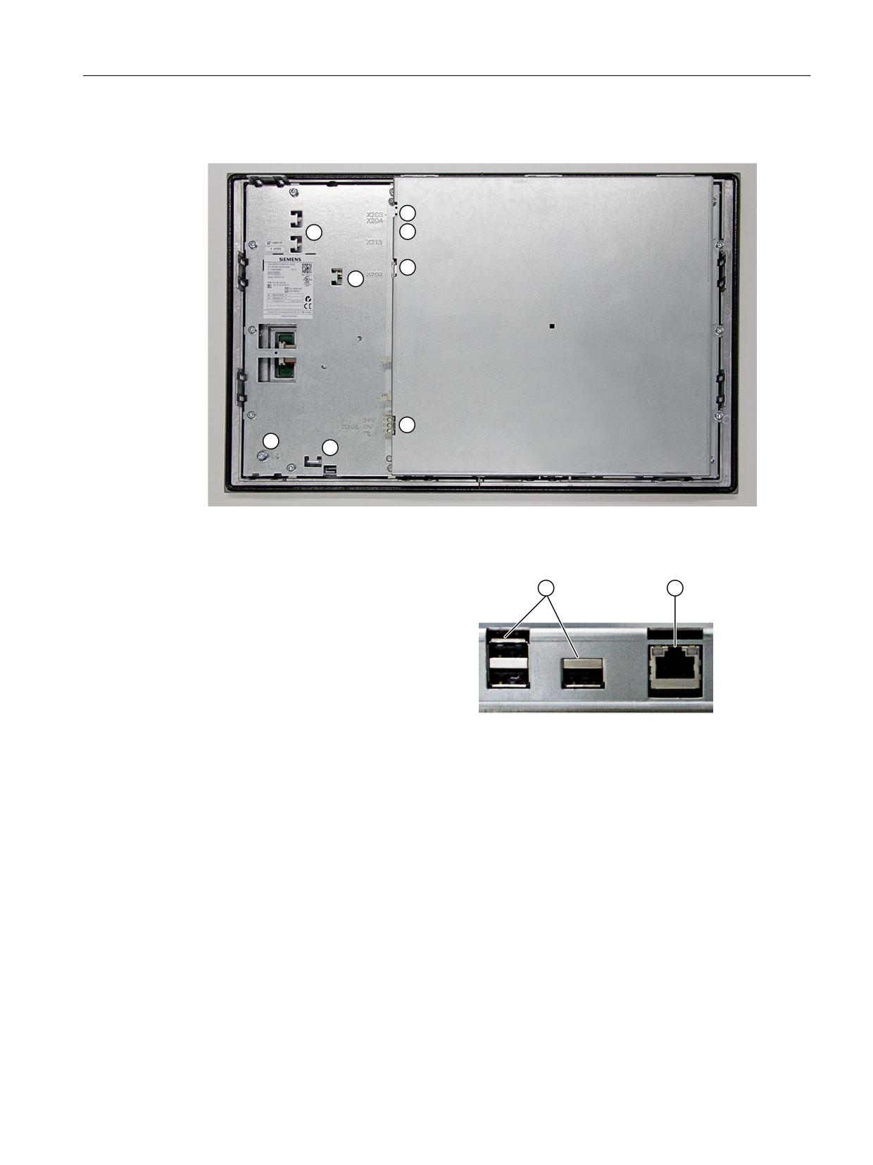
① X206
Power supply (with connector that can be screwed in place)
② -
Strain relief for connecting cables
③ -
M5 grounding screw (for screw connection with cable lug)
④ X203 / X 204 / USB interfaces
X213
⑤ X202
Ethernet interface
Image 11-2 OP 015 black - rear with interfaces
Pin assignment
The pin assignment of the interfaces, see "General information and networking" →
"Connecting".
Operator panels
Manual, 03/2016, 6FC5397-1AP40-5BA3
169
Operator panel front: OP 015 black
11.4 Assembly
11.4
Assembly
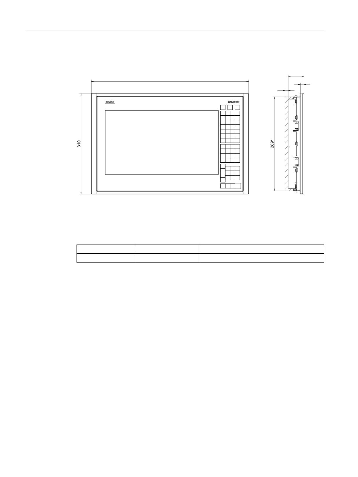
37
483
11
10*
OP 015 black with TCU (integrated)
* Clearance for cable and ventilation
Table 11-1
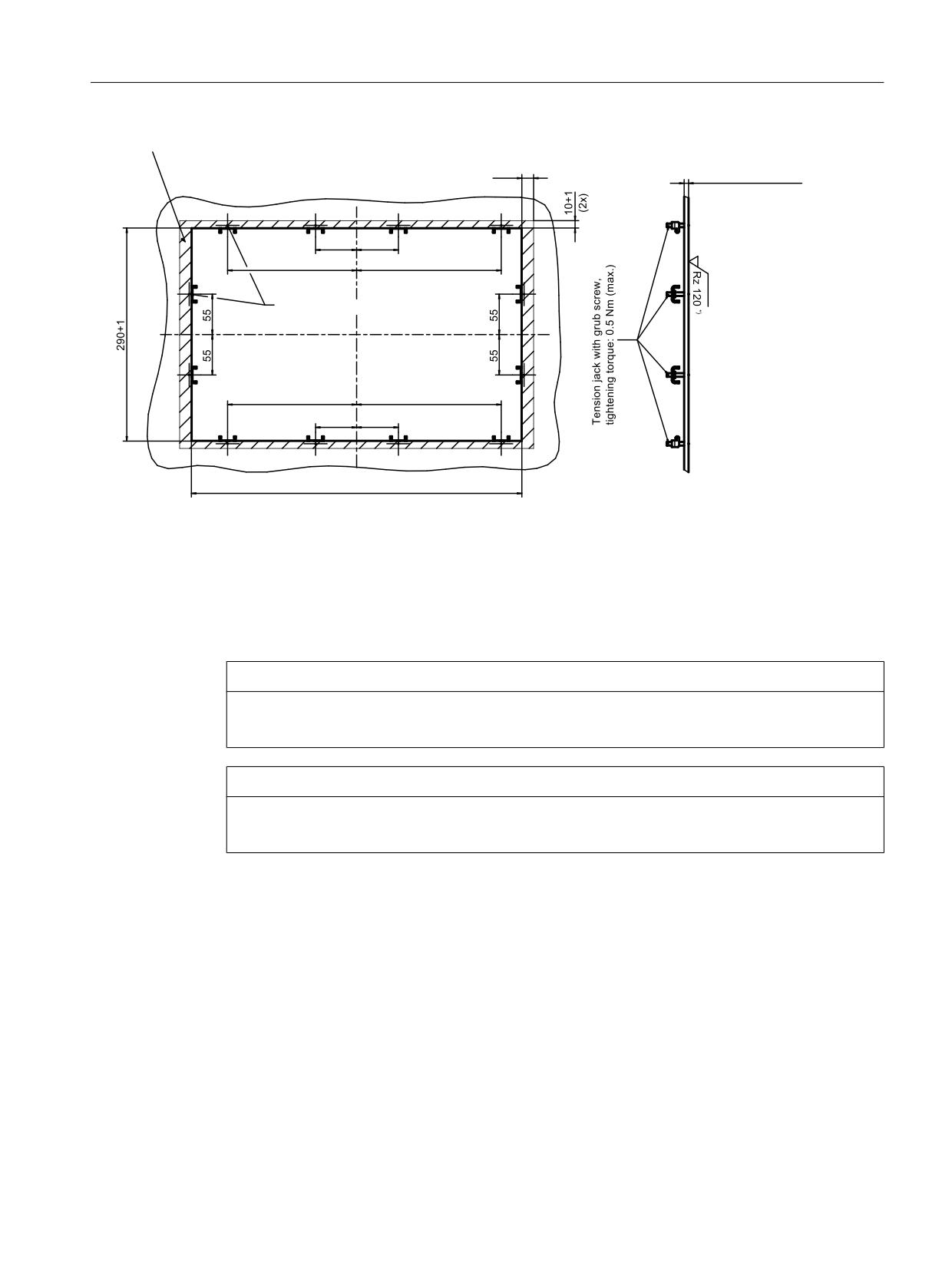
Dimensions of the mounting opening
Width (mm)
Height (mm)
Mounting depth + clearance (mm)
450
290
37 + 10
The OP 015 black is mounted using the tension jacks provided (2.5 mm profile; 20 mm long).
When using the tension jacks, holes or threaded holes are not required.
This mounting method also enables the IP65/IP66 degree of protection if the mounting panel
corresponds to the requirements specified in the dimension drawing. The seal (PU foam seal)
to the mounting panel is already provided on the OP 015 black.
Operator panels
170
Manual, 03/2016, 6FC5397-1AP40-5BA3
Operator panel front: OP 015 black
11.4 Assembly
6HDO DUHD
)RU ,3
PLQ
PD[
[
)RU ,3
PLQ
PD[
3UHVVXUH SRLQWV IRU WHQVLRQ MDFNV
,Q WKH VHDOLQJ DUHD
Image 11-3 Dimension drawing for installing the OP 015 black operator panel front
One person installation
You should also observe the data provided in Section "General information and networking"
→ "Application planning" → "Climatic and mechanical environmental conditions" → "Cooling".
NOTICE
Impermissible mounting positions can cause malfunctions
Observe the permissible mounting position: Deviating by up to 45º from the vertical.
NOTICE
Damage to the glass front
Do not use suction grippers to lift the glass front.
Operator panels
Manual, 03/2016, 6FC5397-1AP40-5BA3
171
Operator panel front: OP 015 black
11.4 Assembly
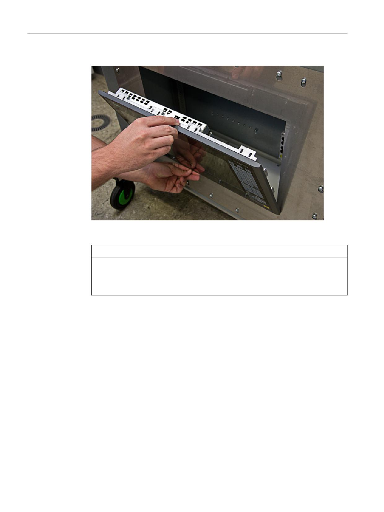
1. Insert the operator panel front in the panel cutout from the front.
Image 11-4 Inserting the operator panel
NOTICE
Damage to the sealing
The seal must not be damaged when installing the device so that the maximum achievable
degree of protection can be fulfilled. Therefore, insert the OP 015 black centered in the
panel cutout.
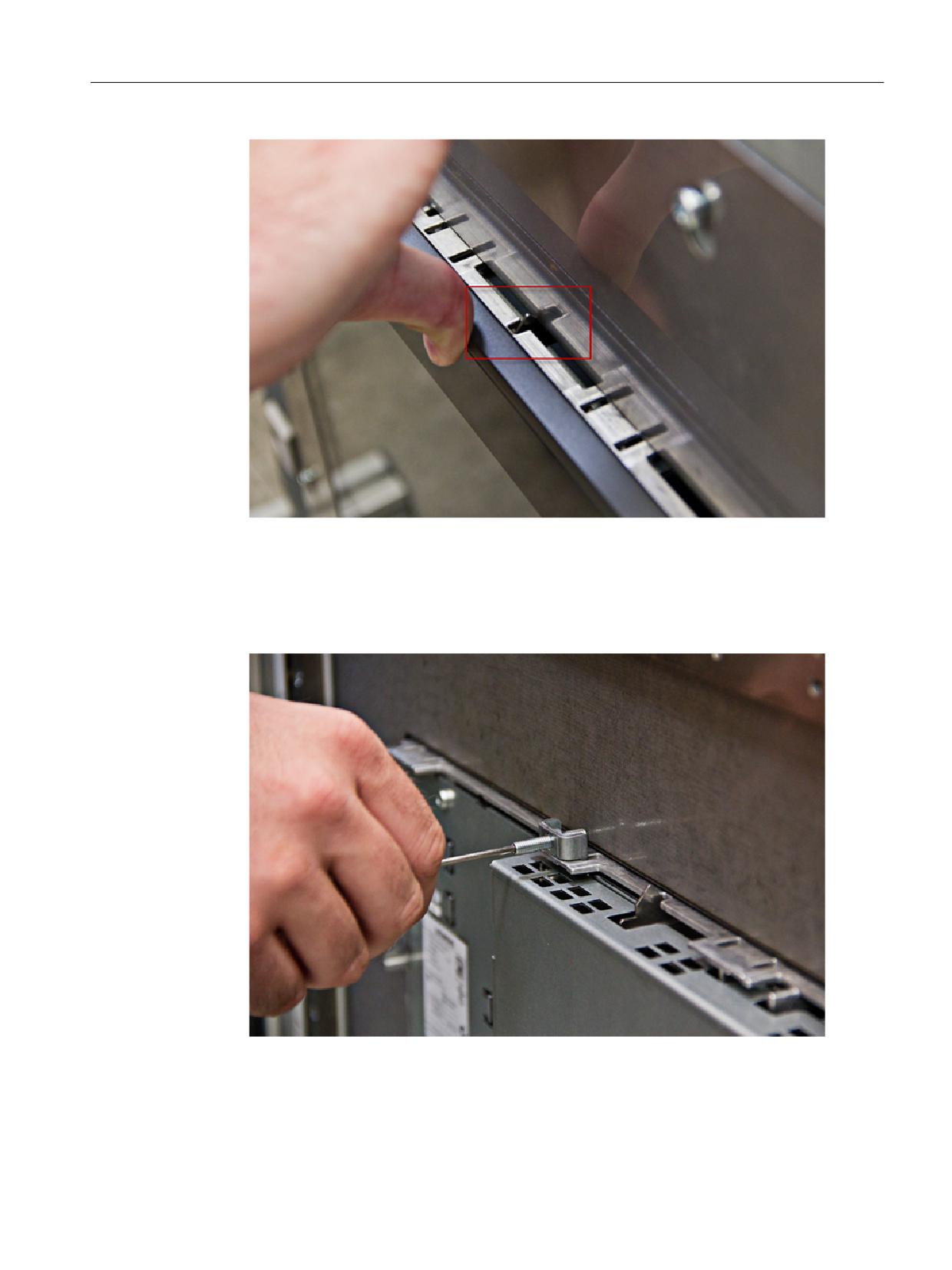
2. Tilt and press the operator panel front into the panel cutout. The catches must be pressed
down.
Operator panels
172
Manual, 03/2016, 6FC5397-1AP40-5BA3
Operator panel front: OP 015 black
11.4 Assembly
Image 11-5 Tilting and pressing in
3. Make sure that the operator panel front sits firmly in the panel cutout and cannot fall out
before you secure it at the rear with the tension jacks.
4. Secure the operator panel front in the panel cutout from the rear using the 12 tension jacks
by tightening the setscrews (torque 0.4 - 0.5 Nm).
Image 11-6 Tightening the tension jacks
Operator panels
Manual, 03/2016, 6FC5397-1AP40-5BA3
173
Operator panel front: OP 015 black
11.5 Technical data
11.4.1
Touchscreen calibration
Whenever a new operator panel front is connected the touchscreen must be calibrated.
Procedure
For a description of the calibration, refer to Chapter Auto-Hotspot.
11.5
Technical data
Safety
Safety class
III; PELV according to EN 50178
Degree of protection accord-
Front: IP65 / IP66
ing to EN 60529
Rear: IPXXB
Approvals
CE / cULus
Electrical data
Power supply 1)
24 VDC (20.4 V ... 28.8 V)
Current consumption
Typical, approx. 1.0 A
Maximum, approx. 2.0 A
Power consumption
Typical, approx. 24 W
Maximum, approx. 42 W
Mechanical data
Dimensions
Width: 483 mm
Height: 310 mm
Depth: 48 mm
Weight
Approx. 7 kg
Tightening torques, max.
Tension jack screws:
M3 screws:
M4 screws:
0.5 Nm
0.8 Nm
1.8 Nm
M5 grounding screw: 3 Nm
Permissible ambient temperatures
Operation
0 ... 45 °C (front)
0 ... 55 °C (rear)
Storage
-20 to 60° C
Display
Size / resolution
15.6" / 1366 x 768 pixels
MTBF backlight
Typical 70 000 h at 25º C (dependent on the temperature)
1)
The power supply must be provided as protective extra low-voltage with safe isolation (according to
EN 60204-1, PELV).
Note
Information about the climatic and mechanical environmental conditions is contained in the
associated section under:
"General notes and interconnection" → "Operational planning".
Operator panels
174
Manual, 03/2016, 6FC5397-1AP40-5BA3
Operator panel front: OP 015 black
11.6 Spare parts/accessories
11.6
Spare parts/accessories
The following can be ordered for the OP 015 black:
● Spare part: Tension jacks 6FC5248-0AF14-0AA0 (9 units)
● Accessories: USB extension 6FC5347-0AF01-1AA0
Operator panels
Manual, 03/2016, 6FC5397-1AP40-5BA3
175
Operator panel front: OP 015 black
11.6 Spare parts/accessories
Operator panels
176
Manual, 03/2016, 6FC5397-1AP40-5BA3
Operator panel front: OP 019
12
12.1
Description
The SINUMERIK OP 019 operator panel front is equipped with a 19" TFT color display with a
resolution of 1280 x 1024 pixels and with 16 + 4 horizontal and 16 vertical softkeys. The
2 x 8 vertical softkeys can be used as direct keys.
The KB 483C full CNC keyboard can be used as an input keyboard.
It is fixed from the rear using special clamps that are included in the delivery scope.
Note
It is not possible to use slide-in labels for the softkeys.
Validity
The description applies to the operator panel front:
Type
Key type
Article number
OP 019
Capacitive keys behind a glass front
6FC5303-0AF13-0AA0
Features
● Anti-glare glass front over the entire panel
●
19" mounting format, 9 HU (height units)
● Panel cutout (W x H): 450 x 380 mm
● Limited mounting depth
●
19" TFT flat screen (color) with a resolution of 1280 x 1024 pixels (SXGA)
● Capacitive keys, including optical feedback using LEDs when actuated:
-
16 + 4 horizontal softkeys
-
16 vertical softkeys
● Status LED for the power supply
● Degree of protection: IP65 / IP66
Operator panels
Manual, 03/2016, 6FC5397-1AP40-5BA3
177