SINUMERIK 840D sl Hardware. Manual (2011-2020) - page 2
Networking
5.2 Commissioning TCU
● The following buttons are important for operation as SINUMERIK operator panel:
To configure the SIMATIC Thin Client, press the button "Settings". You therefore open the
"Operator panel service system":
2SHQ
6HWWLQJV
&ORVH
To exit the SINUMERIK mode, press the button "Close".
● To make the configuration settings, press the button:
Select "Configure Thin Client":
&RQILJXUH 7KLQ &OLHQW
&ORVH
To exit the SIMATIC configuration menu, press the button "Close".
● Press the button to activate the integrated keyboard:
Preconditions
To make the following settings, you must be logged on as administrator.
1. Press the "Settings" button:
2. Log on as a administrator using the specified password.
Result: As administrator you can see the complete menu of the SIMATIC Thin Client.
Note
All changes only become effective after pressing the "Enter" button on the "Virtual Keyboard"
on the relevant side.
General information and networking
Manual, 03/2016, 6FC5397-1AP40-5BA3
69
Networking
5.2 Commissioning TCU
SINUMERIK mode when restarting
In order to return to the SINUMERIK mode automatically after a restart, proceed as follows:
1. In the "Applications" menu, select the "Autostart client application" tab.
2. Select the "SINUMERIK" option.
Calibrate Touch Panel
To calibrate the Touch Panel, proceed as follows:
1. In the "Device setup" menu, select the "Touch calibration" tab.
2. Follow the instructions and touch the Touch Screen at the appropriate points to calibrate.
5.2.7
Settings in the "config.ini" file
Boot server
The active boot server (DHCP server) is detected and displayed in the System Network Center
(SNC). The boot server accesses this configuration file accordingly. Changes to the config.ini
file do not become effective until the relevant TCU or PCU is next booted.
Note
If too much time (> 15 min.) elapses between commands when the user is making entries (e.g.
TCU name) as part of the initial TCU log-on process, the time-out error will be suppressed. No
error message will appear and the FTP connection will be reopened.
The config.ini file is created in the following directories:
NCU:
/user/common/tcu/<TCU name>/common/tcu/
PCU (Windows XP): F:\user_base\common\tcu\<TCU name>\common\tcu\
PCU (Windows 7): C:\ProgramData\Siemens\MotionControl\user\common
\tcu\<TCU name>\common\tcu\
Configuration of the config.ini file
The config.ini file has the following configuration:
Parameter
Range of values
Default setting
Meaning
[Station]
tcuIndex = Number
0 ... 255
DIP | 1
for TCU
mcpIndex = Number
1 ... 254
DIP | 192
for MCP via Industrial Ethernet
eksIndex = Number
0 ... 255
DIP | 0
for EKS
dckEnable = 0
0 or 1
0
for DCK
MaxHostIndex = Number
Number of nodes (NCU, PCU or PC) to which you can
switch over.
General information and networking
70
Manual, 03/2016, 6FC5397-1AP40-5BA3
Networking
5.2 Commissioning TCU
Parameter
Range of values
Default setting
Meaning
[DEFAULT]
SessionNumber = Number
Password = String
SuspendLock = Number
0 or 1
0
0: No displacement disable
1: Displacement disable set
SuspendPriority = Number
1 ... 10
1
1: Lowest priority
10: Highest priority
StartupPrio = Number
Boot sequence:
The lower the number the higher
the priority
ScreenOnFocus = String | Number
Not relevant
ChannelOnFocus = Number
Not relevant
[host_1]
Address = [hostname | IP-Adresse]
From data file structure
SessionNumber = NUMBER
Password = STRING
SuspendLock = NUMBER
0 or 1
0
0: No displacement disable
1: Displacement disable set
SuspendPriority = NUMBER
1 ... 10
1
1: Lowest priority
10: Highest priority
StartupActive = 0
0 or 1
Display screen after boot
StartupPrio = NUMBER
0 ... not too high
Boot sequence:
The lower the number the higher
the priority
ScreenOnFocus = STRING | NUMBER
Not relevant
ChannelOnFocus = NUMBER
Not relevant
[host_2]
[host_MaxHostIndex]
[T2M2N]
SK1 = ch_grp x
2 x 8 characters
Empty
Softkey inscription (2 lines)
SK2 = ch_grp x
2 x 8 characters
Empty
Softkey inscription (2 lines)
SK3 = ch_grp y
2 x 8 characters
Empty
Softkey inscription (2 lines)
SK32 = ch_grp z
2 x 8 characters
Empty
Softkey inscription (2 lines)
General information and networking
Manual, 03/2016, 6FC5397-1AP40-5BA3
71
Networking
5.2 Commissioning TCU
Note
Connecting an MCP via PROFIBUS
If an MCP is connected via PROFIBUS, then the MCP Index = 0 should be set.
Compatibility of software versions
If a "config" file is available for the TCU, the data file structures of older versions are transferred
to the config.ini file and the data file structure is then deleted.
Comment
In the config.ini file comment lines are indicated by the # character preceding a line.
5.2.8
Settings in the "TCU.ini" file
Directories
The tcu.ini files is created in the following directories:
NCU:
/siemens/system/etc/tcu.ini
/user/system/etc/tcu.ini
/oem/system/etc/tcu.ini
PCU (Windows XP): F:\addon_base\system\etc\tcu.ini
F:\user_base\system\etc\tcu.ini
F:\oem_base\system\etc\tcu.ini
PCU (Windows 7):
C:\ProgramData\Siemens\MotionControl\siemens\System
\etc\tcu.ini
C:\ProgramData\Siemens\MotionControl\user\System
\etc\tcu.ini
C:\ProgramData\Siemens\MotionControl\oem\System\etc
\tcu.ini
Note
Only the following entries are evaluated by SINUMERIK Operate:
● VNCServer/VetoMode
● VNCServer/AlarmBoxTimeOut
● VNCServer/FocusTimeout
● VNCServer/AdaptResolution
● VNCServer/MaxActiveTCUs
● VNCViewer/ExternalViewerSecurityPolicy
General information and networking
72
Manual, 03/2016, 6FC5397-1AP40-5BA3
Networking
5.2 Commissioning TCU
Structure and content
In the tcu.ini file comment lines are indicated by the # character preceding a line.
[VNCServer]
# VETO MODE
# VetoMode enabled:
# VNC server notifies the HMI regie before another
# panel gets the focus.
# VetoMode disabled:
# Focus timeout mode enabled (implicitly; see FOCUS TIMEOUT)
# (0=DISABLE, 1=ENABLE)
VetoMode=1
# FOCUS TIMEOUT
# Guaranteed time period (in sec) a panel can hold the
# focus at least before another panel can get the focus.
# The time period starts from the moment the panel has
# gained the focus.
FocusTimeout=10
# ALARMBOX TIMEOUT
# The time period (in sec) a messagebox is shown (i.e. is
# operable) in the case of VetoMode=1; no meaning else
AlarmBoxTimeOut=5
# RESOLUTION
0 = SYSTEM
1 = AUTO_OP_1 (default)
2 = AUTO_OP_2
3 = AUTO_MON_1
4 = AUTO_MON_2
5 = 640X480
6 = 800X600
7 = 1024X768
8 = 1280X1024
General information and networking
Manual, 03/2016, 6FC5397-1AP40-5BA3
73
Networking
5.2 Commissioning TCU
# RESOLUTION ADAPTION
# AdaptResolution enabled:
# At system runtime, the system resolution is automatically
# adapted to the resolution of that panel which
# currently owns the focus.
# AdaptResolution disabled:
# The system resolution is set at system startup phase.
# At system runtime, system resolution remains unchanged
# whichever resolution the currently focused panel owns.
# (0=DISABLE, 1=ENABLE)
AdaptResolution=1
# COLOR DEPTH
# The value the system color depth is set at system
# startup phase
# ColorDepth SYSTEM:
# System color depth remains unchanged whichever value
# the color depth is currently set to.
# COlorDepth 16_BIT
# System color depth is set to 16 bit.
# COlorDepth 32_BIT
# System color depth is set to 32 bit.
# (0=SYSTEM, 1=16_BIT, 2=32_BIT)
ColorDepth=1
# INIT TIMEOUT
# Guaranteed time period (in sec) the HMI manager waits
# for VNC server initialization.
InitTimeout=300
# PCU STARTUP TIMEOUT
# Attention: The parameter is only provided for a PCU
# configuration with local attached OP !
#
# The startup phase is completed if this timeout period
General information and networking
74
Manual, 03/2016, 6FC5397-1AP40-5BA3
Networking
5.2 Commissioning TCU
# has passed and no registration of a TCU has been car-
# ried out at this time.
PCUStartupTimeout = 90
# TCU STARTUP STEP TIME
# The startup phase starts at the first TCU registration.
# The startup phase is completed if the TCUStartupStepTime
# period has passed and no registration of another TCU has
# been carried out at this time.
TCUStartupStepTime = 30
[VNCViewer]
# EXTERNAL VIEWER MAX CONNECTIONS
# Maximum number of external Viewer Connections (1 or 2)
# ExternalViewerMaxConnections=2
ExternalViewerMaxConnections=1
# EXTERNAL VIEWER SECURITY POLICY
# The user rights, assigned to an external VNCViewer
# ExternalViewerSecurityPolicy=0 : no external viewers allowed
# ExternalViewerSecurityPolicy=1 : Guest Mode (View-Only)
# ExternalViewerSecurityPolicy=2 : Administrator Mode
# ExternalViewerSecurityPolicy=1
# EXTERNAL VIEWER MAX REFUSED REQUEST
# Number of refused external viewer requests, after which
# a timeout period is carried out for the viewer.
ExternalViewerMaxRefusedRequest=3
# EXTERNAL VIEWER CONNECTION TIMEOUT
# Timeout Period in seconds, after MaxRefusedRequest
# is reached. No viewer request is possible during the
# Timeout Period.
ExternalViewerConnectionTimeout=240
General information and networking
Manual, 03/2016, 6FC5397-1AP40-5BA3
75
Networking
5.2 Commissioning TCU
# EXTERNAL VIEWER REQUEST TIMEOUT
# The time period (in sec) the request-messagebox is shown (i.e. is
# operable)
ExternalViewerRequestTimeout=20
# EXTERNAL VIEWER REQUEST TIMEOUTMODE
# The behaviour if request-timeout elapsed
# ExternalViewerReqTimeoutMode=0 : dismiss request
# ExternalViewerReqTimeoutMode=1 : accept request
ExternalViewerReqTimeoutMode=1
# REMOTE ACCESS IP-ADDRESS
# IP-V4-format
X127RemoteAccessIP=192.168.215.29
# MODEM IP-ADDRESS
# IP-V4-format
X127ModemIP=192.168.215.30
# SERVICE HOST
# NCU with teleservice adapter on its X127 interface
# Use "Self" for your own X127 interface
# IP-V4-format or DNS-Name or Self
X127ServiceHost=Self
[PingService]
# PING SERVICE MODE
# (0=DISABLE, 1=ENABLE)
PingServiceMode=0
# PING SERVER IP-ADDRESS
# IP-V4-format
PingServerIP=
# PING SENDING DATA
General information and networking
76
Manual, 03/2016, 6FC5397-1AP40-5BA3
Networking
5.2 Commissioning TCU
PingTransmissionData=
# PING SERVER PORT-NUMBER
PingServerPort=
# PING TRANSMISSION PERIOD
# Period in minutes, in which transmission data will be sent
PingTransmissionPeriod=2
# PING TRANSMISSION INTERVAL
# Time interval in seconds between two pings
PingTransmissionInterval=5
[externalTcu]
# EXTERNAL TCU IP-ADDRESSES
# List of accepted TCUs in IP-V4-format (index 1 to maximal 16)
ExternalTcuIP_1=
[TCU_HWSService]
# TCU CONNECT TIMEOUT
# Guaranteed time period (in sec) the HMI manager waits
# for TCUs recognized as connected TCUs by the TCU_HWS
# service.
TCUConnectTimeout=30
# TCU CONNECT TIMEOUT FOR HEADLESS STARTUP
# Guaranteed time period (in sec) the HMI manager waits
# for TCUs recognized as connected TCUs by the TCU_HWS
# service, if a PCU panel doesn't exist and no TCUs are
# connected till now. This time period is effective ad-
# ditionally to the time period TCUConnectTimeout.
HeadlessTCUConnectTimeout=60
General information and networking
Manual, 03/2016, 6FC5397-1AP40-5BA3
77
Networking
5.2 Commissioning TCU
Prerequisite
Note
The "Operation without SINUMERIK OP" option is required when using more than 1 external
VNC Viewer.
Operator control without SINUMERIK OP
If the "Operation without SINUMERIK OP" option is set, then a list of viewers that can be
assigned in tcu.ini is handled by the system just like internal viewers (=TCU); this means that
these viewers have full user authorization and participate in the user rights management.
Towards the outside, they behave just the same as the viewer on the SINUMERIK operator
panels.
Restrictions
Restrictions for such external operator control units are:
● Neither MCP and direct keys nor an EKS system can be assigned. This also means that
these devices cannot be activated to be an operator control unit in the system.
● Direct control keys cannot be triggered, i.e. the softkeys to the direct keys can be triggered
in the operating software. However, the keys do not appear in the direct key image to the
PLC.
● There is no configuration file config.ini, as for a TCU, i.e. the settings to be made to a TCU
are not possible for such an operator control unit (power-up behavior, displacement, t:m:n);
however, the displacement mechanism to the external operator control units is effective.
● An external operator control unit is never signaled as active operator station in the PLC.
Configuring the external operator control units in the tcu.ini file in section:
[externalTcu]
# EXTERNAL TCU IP-ADDRESSES
# List of accepted TCUs in IP-V4-format (index 1 to maximal 16)
ExternalTcuIP_1=
The desired screen resolution can also be set in the file tcu.ini:
[VNCServer]
Resolution = ...
5.2.9
Displacement mechanism for TCUs
Supplementary conditions
The following supplementary conditions apply when operating the TCU:
General information and networking
78
Manual, 03/2016, 6FC5397-1AP40-5BA3
Networking
5.2 Commissioning TCU
2 active TCU connected in parallel to NCU 710.3 PN
4 active TCU connected in parallel to NCU 720.3 PN, NCU 730.3 PN
4 active TCU connected in parallel to PCU
To operate a machine with more operating stations then the maximum number the
displacement mechanism ensures that only the permitted number of TCUs are active in
shadowing grouping. The remaining TCUs are switched to a passive mode, which means they
no longer represent a load relative to the resources. Thus the number of TCUs that can be
connected to one HMI application is practically no longer limited, the limitation is the number
of concurrently active TCUs.
Configuration
There are two new entries in the config.ini file for a TCU for the displacement mechanism:
● SUSPENDLOCK: controls whether the TCU can be displaced via the displacement
mechanism.
SUSPENDLOCK = 0 means that a displacement disable is not set (preset), i.e. the TCU
may be displaced by any other TCU.
SUSPENDLOCK=1 means that this TCU can never be displaced.
● SUSPENDPRIORITY: This entry specifies a priority for the displacement mechanism to the
TCU. In a displacement process the TCUs among the active TCUs with the lowest priority
that do not have a displacement disable will displaced. The priority is specified as numeric
value in the range 1 - 10.
The preset is 1 (lowest priority).
Note
If you set a displacement disable for a TCU then specification of a displacement priority is
unnecessary because it never is used due to the displacement disable.
Displacement rules
The TCU can assume the following states:
● The TCU is active and has user authorization: This can be identified as the TCU shows the
screen of the operating software and the screen is bright.
● The TCU is active, however, in the monitoring mode (i.e. it presently has no user
authorization): This can be identified as the TCU shows the screen of the operating
software, however, it is darkened in comparison to the TCU with user authorization.
● The TCU is passive: The TCU shows the selection menu of the possible connections
instead of a screen of the operating software, and the softkey for selection of the last active
connection of the TCU is shown in color.
When a TCU boots, the TCU always attempts to establish the first connection specified in its
config file. The TCUs from a shadowing group establish their specified connection one after
the other as long as the maximum number of permissible active operator units is not exceeded.
If a TCU encounters the situation that this number is already reached in its power up, then it
attempts to obtain a connection via the displacement mechanism. If it can displace a formerly
General information and networking
Manual, 03/2016, 6FC5397-1AP40-5BA3
79
Networking
5.2 Commissioning TCU
active operator unit then it takes on the active status itself, otherwise it transitions to passive
status immediately after booting.
5.2.10
Disable switchover between TCU via PLC
Overview
The TCU switchover disable offers the option of dynamically disabling switchover from one
TCU to the next when the system is running via the PLC. For the duration of the disable, a
user authorization request to change user authorizations between TCUs will be ignored by the
system and rejected.
The rejected user authorization request causes a message to be output in the dialog line of
the HMI, in the form of a feedback message for the requester. The message disappears after
five seconds.
HMI ↔ PLC data interface
The “switchover disable” function is always active and does not have to be switched on
explicitly. The function is controlled by a data bit in the PLC. The HMI transfers the active OP
to the PLC, thus forming the basis of the control function in the PLC.
The control bits and control information for this function are stored in the m:n data interface of
the PLC. In terms of m:n, this function can be operated separately for the currently overridden
HMIs in both m:n online interfaces (DB19.DBW120 ff for HMI1 and DB19.DBW130 ff for HMI2).
If a system is not running an m:n, only the first m:n online interface is used for this function.
Switchover disable is controlled by a TCU_SHIFT_LOCK bit, managed by the user, on each
HMI in the PLC. The bit address for the first HMI is DB19.DBB126.6 and DB19.DBB136.6 for
the second HMI.
The PLC m:n online interface is expanded so that byte DB19.DBB118 is still added to the first
interface and byte DB19.DBB119 to the second. These bytes acquire the index of the active
TCU (of the active OP) for the appropriate HMI. The byte is called TCU_INDEX. The
appropriate HMI uses the TCU index configured for the active TCU to describe the TCU_INDEX
byte.
The TCU_SHIFT_LOCK bit is monitored by the appropriate HMI. A value = 1 triggers the
switchover disable; switchover is enabled if the value returns to 0. The TCU_SHIFT_LOCK bit
can be set, for example, to the PLC by the user pressing a key or it can be managed by the
PLC user program according to its own logic. The TCU_SHIFT_LOCK bit is managed in the
PLC exclusively by the user; the HMI only accesses this bit in read-only mode.
The HMI assigns the configured index of the TCU or PCU whose OP currently possesses user
authorization in the shadow grouping. If no OP is active, a value of 0 is entered in TCU_INDEX.
If no TCU index is configured for the active TCU (active OP), the value 255 = undefined is
presented as the TCU index. This means that the values 0 and 255 may not be configured as
the TCU index.
General information and networking
80
Manual, 03/2016, 6FC5397-1AP40-5BA3
Networking
5.2 Commissioning TCU
Configuration
The TCU index and machine control panel address (MCP address) are configured on the PCU.
The TCU index is set in the "OP Properties" dialog of the "System Network Center" program.
Operating principle
If the TCU_SHIFT_LOCK bit is set for switchover disable, a user authorization request is not
carried out independently of the mode set on the HMI for allocation of user authorizations (veto
mode), i.e., a change of user authorization is rejected.
This message appears on all OPs for approximately 5 seconds:
"No switchover: Switchover disable set in current PLC."
While this message is displayed, operations on the OP with the user authorization can still be
carried out unaffected.
Note
The switchover disable only relates to changing the user authorization on the OPs in a
shadowing grouping on a PCU.
Active switching from one OP to another PCU is not prevented.
Special features
The following special cases should be noted:
● Even if switchover disable is set, the TCU_INDEX field value may change in the PLC. This
is the case if:
- The OP in possession of the user authorization is actively switched to another PCU.
Depending on whether another TCU takes on the user authorization or whether no TCU
is currently active, either the index of the TCU or the PCU itself (if its directly connected
OP becomes active) is entered, in exactly the same way as when there is a user
authorization switchover.
This can also be the value 255, if no TCU index is available for the OP. 0 is entered if
an OP is no longer available in the shadow grouping.
- An m:n switchover is in progress. The HMI program of the incoming PCU deactivates
the HMI program which is active on it. An OP from the shadow grouping of the new
(incoming) PCU must receive the user authorization. The TCU index of this OP is
entered in the TCU_INDEX field.
- A PCU is disconnected from a NCK/PLC in the context of m:n. No HMI program and,
therefore, no OP with user authorization is then available on the exited NCK/PLC. This
is signaled independently of a switchover disable by entering the value 0 into the
TCU_INDEX field.
● If a TCU is actively switched over to another PCU, it can be deactivated there, i.e. it does
not obtain the user authorization, if a switchover disable is set for the destination PCU.
General information and networking
Manual, 03/2016, 6FC5397-1AP40-5BA3
81
Networking
5.2 Commissioning TCU
● With an m:n PCU switchover - the PCU is switched to another NCK and, therefore, to
another PLC - the PCU takes on the switchover disable settings of that PLC.
● The m:n interlock options on the PLC side have priority over the TCU switchover disable,
so that a set TCU switchover disable cannot prevent an m:n switchover. If necessary, the
m:n interference options should be synchronized here with those for the TCU in the PLC.
It may, for example, be practical to set or remove the m:n displacement disable
simultaneously with the TCU switchover disable.
Obtaining user authorization
On a TCU that has no user authorization, the first key that is pressed serves exclusively to
request the user authorization, i.e. this key is not evaluated by the operating software.
The settings for the right to veto are stored in file tcu.ini and are only effective if the operating
software is installed on the PCU. At the OP of the TCU, the operating software can be operated
in exactly the same way as an OP directly connected to the PCU.
Note
These operator input sequence steps must only be carried out by qualified personnel!
5.2.11
Example: How to select the behavior of the TCUs during boot up
Example: Distributing boot support across two PCUs
To distribute boot support over two PCUs, "Boot support runtime and configuration only (TFTP/
FTP)" must be selected on PCU_1 and "Boot support IP address only (DHCP)" must be
selected on PCU_2.
The "No boot support" configuration must be selected on PCU_3:
Table 5-1
"TCU support" settings
TCU_1
TCU_2
TCU_3
TCU_4
192.168.214.10
192.168.214.11
192.168.214.12
192.168.214.13
VNC connections:
VNC connections:
VNC connections:
VNC connections:
192.168.214.241
192.168.214.241
192.168.214.241
192.168.214.241
192.168.214.242
192.168.214.243
192.168.214.243
192.168.214.242
192.168.214.243
Switch to system network
PCU_1
PCU_2
PCU_3
192.168.214.241
192.168.214.242
192.168.214.243
General information and networking
82
Manual, 03/2016, 6FC5397-1AP40-5BA3
Networking
5.3 Network configuration
Services:
Services:
Services:
X DHCP
✔ DHCP
X DHCP
✔ TFTP
X TFTP
X TFTP
✔ FTP
X FTP
X FTP
✔ VNC
✔ VNC
✔ VNC
Company network
In this case, PCU_2 serves as the DHCP server which provides the IP addresses for the
connected TCUs. PCU_3 is not involved in booting the TCUs, it is however displayed by the
TCUs using VNC.
5.3
Network configuration
5.3.1
Permissible network topologies
Ethernet connection
A SINUMERIK 840 D sl can only be operated as a network within which the individual
components communicate with one another via Ethernet connections. This network must be
set up.
The individual components are factory-set so that the most frequently occurring standard
configurations can be operated without changing the settings related to the network.
Division into system network and company network
On the SINUMERIK solution line, the components are generally split into a company network
on the one hand and a system network on the other.
The connection to the company network provides access to the network drives, for example.
On the system network, process data communication and image transmission runs from the
components with operator software to the display units - the respective TCU.
This split is performed physically by means of the prescribed use of the Ethernet interfaces on
the components:
● A TCU is connected exclusively to the system network.
● An NCU is always connected to the system network via X120.
● Ethernet interface Eth 2 of the PCU is preconfigured for connection to the system network;
while Ethernet interface Eth 1 is used for connection to the company network.
● An NCU is connected to the company network via X130.
Meaning of the connections:
○
Eth 1 as a DHCP client
●
Eth 2 as a DHCP server
General information and networking
Manual, 03/2016, 6FC5397-1AP40-5BA3
83
Networking
5.3 Network configuration
■
Eth 2 with a fixed IP address
Green connection
Uncrossed Ethernet cable
Gray connection
Crossed Ethernet cable (crossover)
5.3.2
Networks without connection to the company network
5.3.2.1
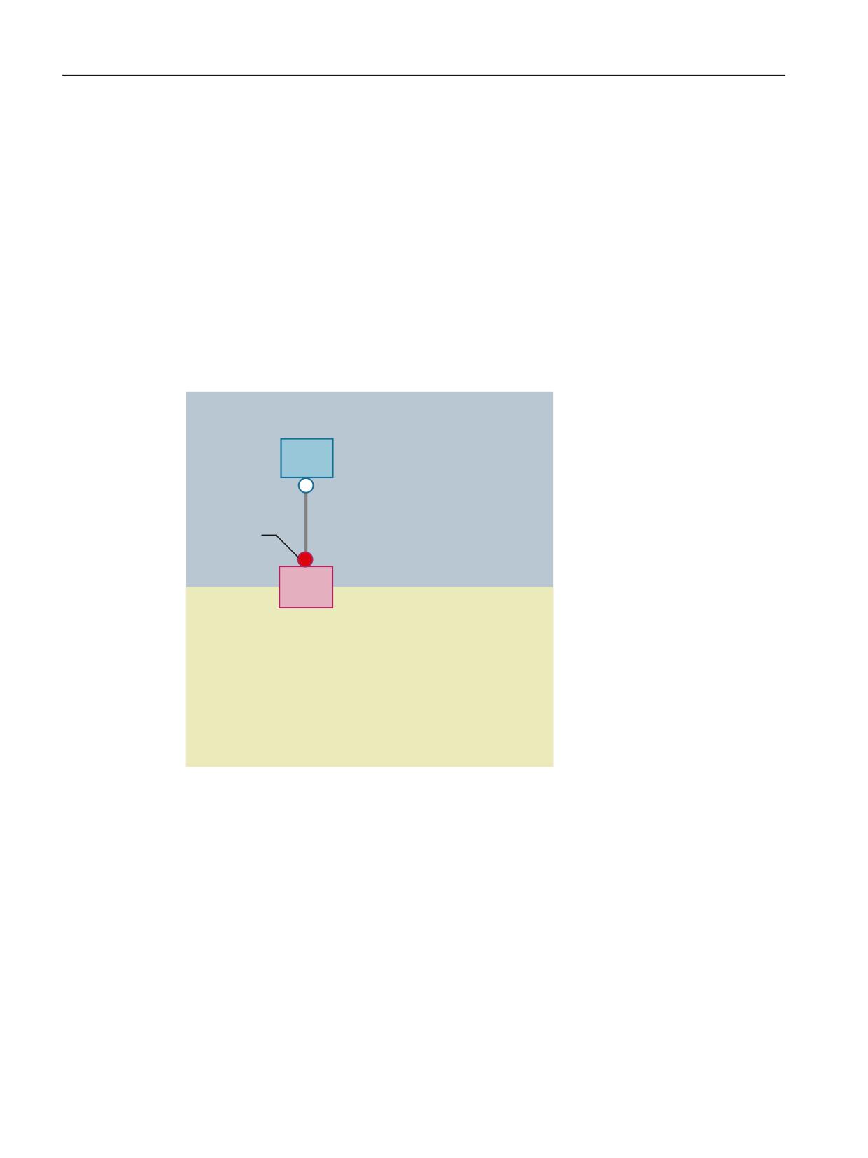
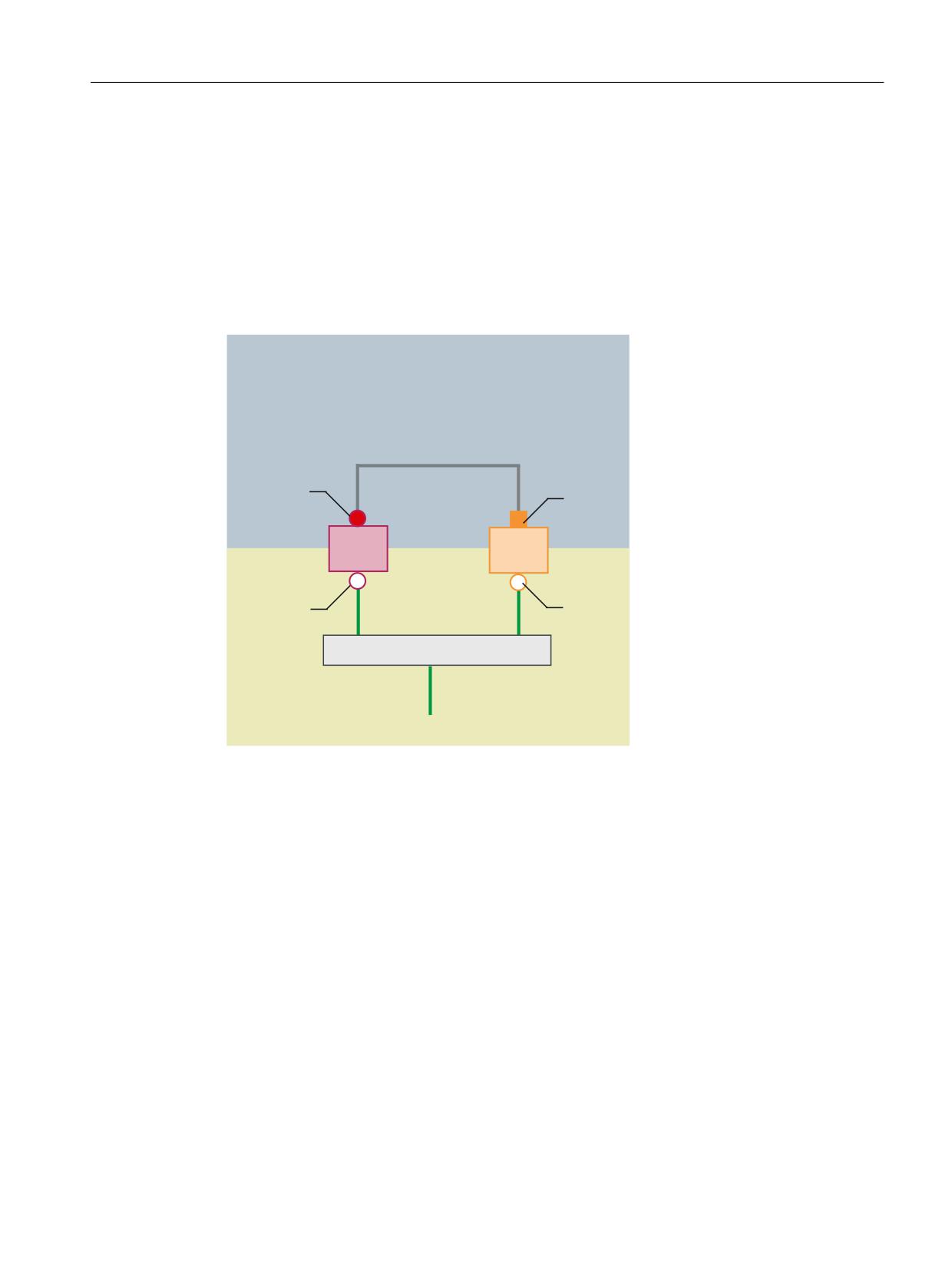
Configuration 1: NCU and TCU
Description
6\VWHP QHWZRUN
7&8
;
1&8
&RPSDQ\ QHWZRUN
A direct Ethernet connection is used to connect a TCU to X120 of the NCU. NCU and TCU
are suitably preconfigured with IP addresses.
The IP addresses are not significant for further operation.
The TCU is connected to the NCU via a crossed Ethernet cable.
The direct connection of the NCU via X120 to the TCU automatically forms a simple system
network consisting of two computer nodes.
General information and networking
84
Manual, 03/2016, 6FC5397-1AP40-5BA3
Networking
5.3 Network configuration
5.3.2.2
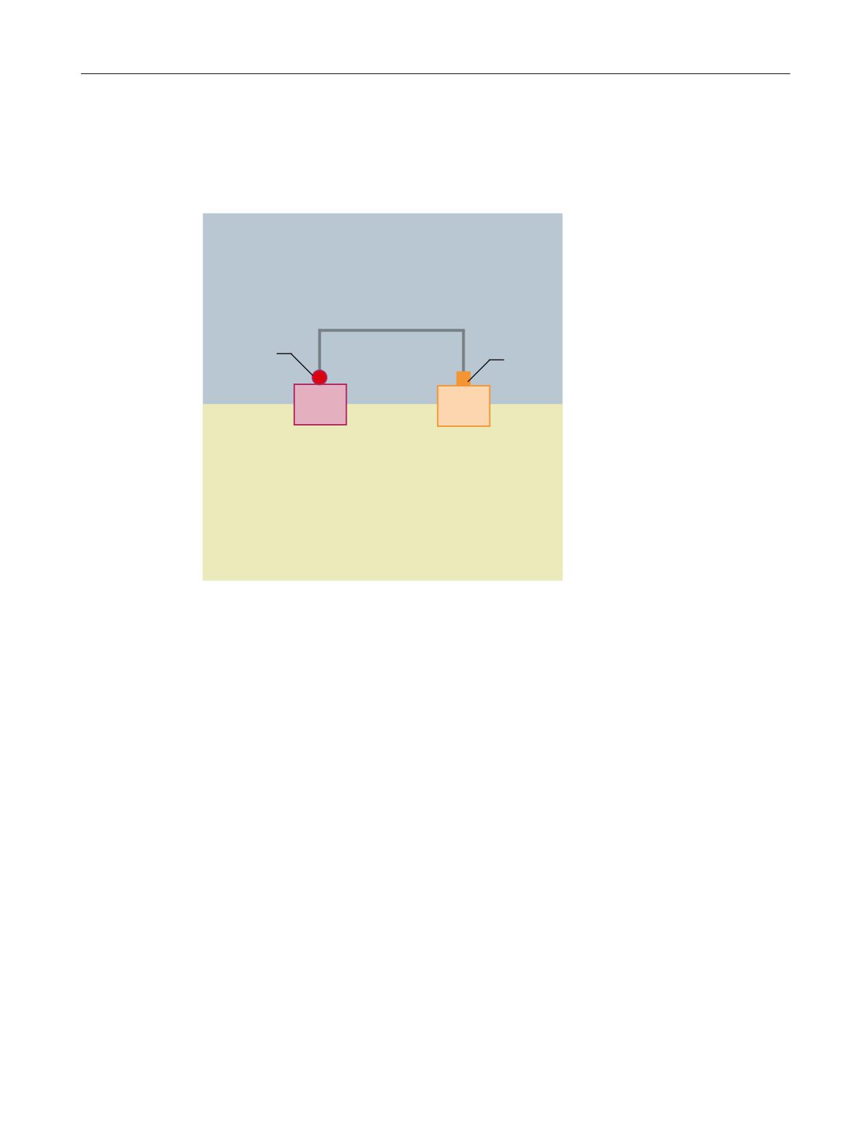
Configuration 2: NCU and PCU with direct OP
Description
6\VWHP QHWZRUN
;
(WK
1&8
3&8
&RPSDQ\ QHWZRUN
The NCU and PCU are connected via a crossed Ethernet cable.
The NCU is the DHCP server with the IP address 192.168.214.1.
For this Eth 2 configuration, the PCU is assigned a fixed IP address in the range
192.168.214.241 - 192.168.214.249 with a subnet mask 255.255.255.0 .
General information and networking
Manual, 03/2016, 6FC5397-1AP40-5BA3
85
Networking
5.3 Network configuration
5.3.3
Networks with NCU connection to the company network
5.3.3.1
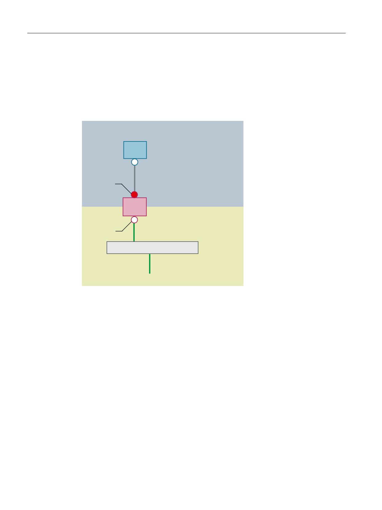
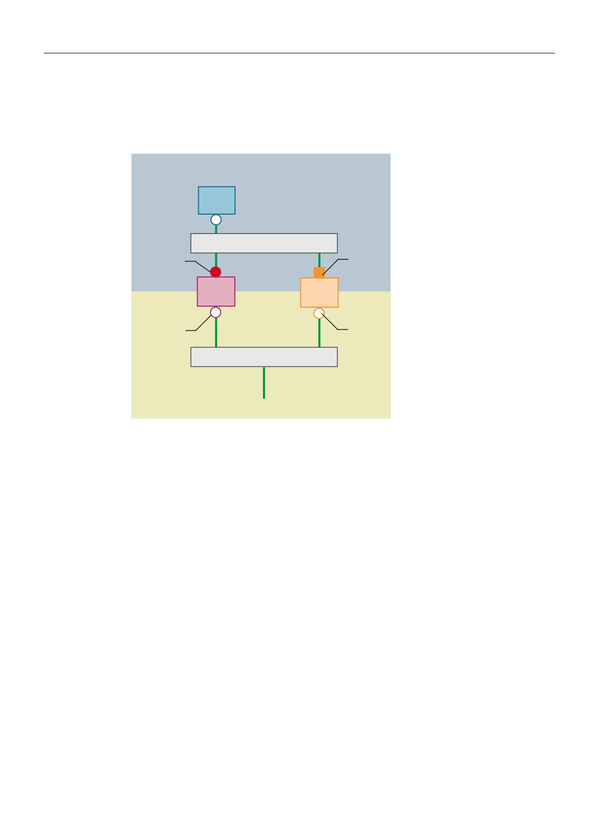
Configuration 3: NCU and TCU
Description
6\VWHP QHWZRUN
7&8
;
1&8
;
6ZLWFK
&RPSDQ\ QHWZRUN
The TCU is connected to the NCU (directly) using a crossed Ethernet cable. On X130, the
NCU is connected to a switch to the company network with a straight cable.
As in configuration 1, there is a direct Ethernet connection between a TCU and X120 of the
NCU. NCU and TCU are suitably preconfigured with IP addresses. The IP addresses used
here are not significant for further operation.
IP configuration: DHCP server on the company network
On X130, the NCU is set to the address reference via DHCP. If the company network has a
DHCP server that provides the NCU with an IP address (IP configuration), the NCU is
integrated into the company network.
Depending on the infrastructure available or the level of network administration of the company
network, the following network parameters must be set for the NCU on X130:
● Computer name on the company network
● Address of a DNS server
● Address of a gateway (default router)
The IP address of the NCU to this connection is also assigned via network administration.
General information and networking
86
Manual, 03/2016, 6FC5397-1AP40-5BA3
Networking
5.3 Network configuration
If the company network offers a low level of administration (in the worst case scenario the
network has only one DHCP server that assigns the addresses from a predefined address
range) the NCU receives an IP address that is initially unknown.
5.3.3.2
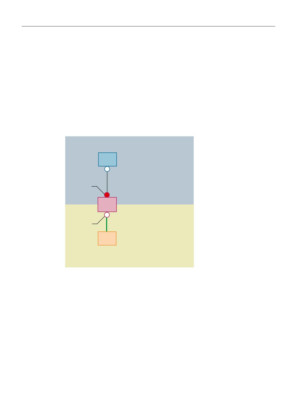
Configuration 4: NCU and PCU with direct OP
Description
6\VWHP QHWZRUN
;
(WK
1&8
3&8
;
(WK
6ZLWFK
&RPSDQ\ QHWZRUN
The NCU and PCU are connected via a crossed Ethernet cable.
On X120, the NCU occupies the fixed IP address 192.168.214.1 in its capacity as a DHCP
server (not used in this configuration). For this Eth 2 configuration, the PCU is assigned a fixed
IP address in the range 192.168.214.241 - 192.168.214.249 with a subnet mask
255.255.255.0 .
The observations made for configuration 3 also apply here in relation to the connection to the
company network. The connection to a switch on the company network is made via a non-
crossed Ethernet cable.
General information and networking
Manual, 03/2016, 6FC5397-1AP40-5BA3
87
Networking
5.3 Network configuration
5.3.3.3
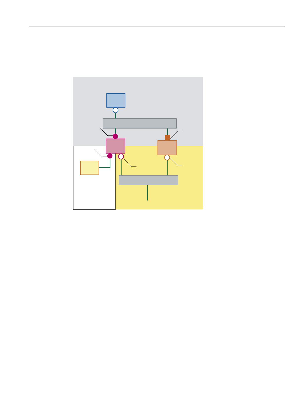
Configuration 5: PCU with TCU on NCU
Description
6\VWHP QHWZRUN
7&8
6ZLWFK
;
(WK
1&8
3&8
;
(WK
6ZLWFK
&RPSDQ\ QHWZRUN
In this configuration, a switch is also required for the system network. All components are
connected using straight Ethernet cables.
In terms of address allocation and the settings that need to be made, this configuration is
identical to that of configuration 4. However, in this case, the DHCP server of the NCU actually
supplies the TCU with an IP address and serves as a boot server for the TCU.
The observations made for configuration 3 also apply here in relation to the connection to the
company network. The connection to a switch on the company network is made via a straight
Ethernet cable.
To connect one TCU to both HMI systems you must create an additional connection to the
NCU for the TCU, as described in the following chapter:
General information and networking
88
Manual, 03/2016, 6FC5397-1AP40-5BA3
Networking
5.3 Network configuration
5.3.3.4
Connecting the programming device (PG) to the NCU
Description
$QODJHQQHW]
7&8
6ZLWFK
;
(WK
1&8
;
3&8
(WK
3*
;
6ZLWFK
)LUPHQQHW]
For service purposes a programming device is connected to the NCU at X127 as a standard
DHCP client (automatically obtain an IP address). An NCU is a standard DHCP server on
X127. On X127, the NCU occupies the fixed IP address 192.168.215.1 with the subnet mask
255.255.255.224.
At X127, IP addresses from 192.168.215.2 onwards are assigned via DHCP; e.g. to connect
a programming device. This is the reason that a fixed IP address must not be set at the
programming device.
5.3.4
Example: Configuring a VNC connection to a PC
Requirements
In order to use a TCU to get visual access to a computer from a SINUMERIK system via VNC,
the following requirements apply:
● The boot server (active DHCP server) in the system network must be an NCU.
● This NCU must be integrated via X130 or X120 into the network to which the computer to
be monitored is connected.
General information and networking
Manual, 03/2016, 6FC5397-1AP40-5BA3
89
Networking
5.3 Network configuration
● The computer to be monitored must be configured in the config.ini configuration file of the
TCU according to the general configuration for a TCU in a separate host section as a
switchover target for this TCU.
Where necessary, a password has to be specified in the configuration, if the VNC server
requires one on the target system (see below).
● To ensure that the TCU recognizes the new switchover target, the TCU requires a restart
and reboot.
● The screen resolution of the computer to be monitored must be adjusted to the conditions
of the TCU, since otherwise the TCU scales the image received to its possible range of
representation, which would adversely affect the representation on the TCU.
Configuration
6\VWHP QHWZRUN
7&8
;
1&8
;
3* 3&
1HWZRUN
Image 5-17 Configuration example
Configuration
The config.ini file is located in the following directory:
NCU:
/user/common/tcu/<TCU name>/common/tcu
PCU (Windows XP):
F:\user_base\common\tcu\<TCU name>\common\tcu
PCU (Windows 7):
C:\ProgramData\Siemens\MotionControl\user\common
\tcu\<TCU name>\common\tcu
The config.ini file must be stored on the boot server (active DHCP).
Example:
General information and networking
90
Manual, 03/2016, 6FC5397-1AP40-5BA3
Networking
5.3 Network configuration
[Station]
maxhostindex=2
/* Number of nodes that are defined under
[host_1] and [host_2].
mcpIndex=192
tcuIndex=1
eksIndex=0
[host_1]
Address=192.168.214.1
/* Address of the NCU to which the
connection is established during booting.
[host_2]
Address=157.163.230.202
/* Address of the PC
password=123456
/* Password of the VNC server on the PC
Switching over between the nodes
With the "Menu back" + MENU SELECT keys, the following actions are triggered:
● In the header of the displayed window you will see the TCU name, for example TCU1.
● A selection list for connecting to the other nodes will be displayed on the TCU.
See also
Settings in the "config.ini" file (Page 70)
5.3.5
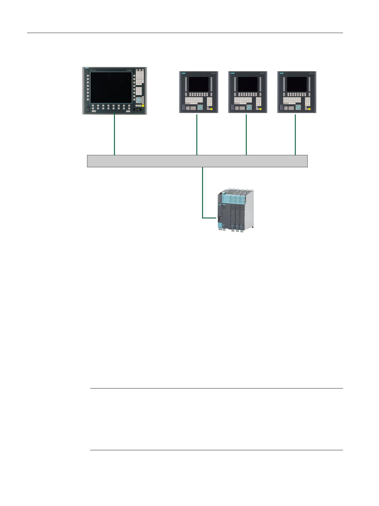
Application example
Application
The configuration is suitable for the following application: Machine with concurrent operating
option to two operator panels , a full-featured operating panel with PCU and an operator panel
reduced to tool management.
Parallel operation of HMI-Advanced or SINUMERIK Operate on the PCU 50.3 and
SINUMERIK Operate as component of the CNC software on the SINUMERIK 840D sl NCU:
Any OP connected to PCU 50.3 and any OP connected to the NCU can be simultaneously
operated: in the example, OP 08T.
General information and networking
Manual, 03/2016, 6FC5397-1AP40-5BA3
91
Networking
5.3 Network configuration
3&8
23
7
23
7
23
7
6ZLWFK
6\VWHP QHWZRUN
6,180(5,.
' VO
Image 5-18 Configuration example
Proceed as follows
To configure the application example, proceed as follows:
1. PCU 50.3 with HMI Advanced
Deactivate the DHCP server on the PCU: For this select the option "Boot support runtime
and configuration only (TFTP/FTP)" on the "TCU support" tab of the "System Network
Center" program.
2. SINUMERIK 840D sl from CNC software, version 2.4 and higher
The systemconfiguration.ini configuration file is included on the SINUMERIK 840D
sl product DVD.
3. OP 08T operator panel
Once the installation of the OP 08T operator panel with SINUMERIK Operate has been
completed, copy the systemconfiguration.ini file from the /Siemens/
sinumerik/hmi/appl/systemconfig/tm/ directory to the /oem/sinumerik/hmi/
cfg/ directory. After this, a system restart is necessary.
Note
Subsequent changes
Once the file has been copied, no further settings (e.g. changing language) can be
implemented on the SINUMERIK Operate. If you want or need to implement changes later,
the systemconfiguration.ini file can be renamed (e.g., as systemconfiguration.save). After
this, a system restart is necessary. Following the restart, the full functional scope of
SINUMERIK Operate is available once again.
General information and networking
92
Manual, 03/2016, 6FC5397-1AP40-5BA3

Networking
5.4 Service and diagnostics
5.4
Service and diagnostics
5.4.1
Booting of the TCU
Messages when booting
While the TCU is booting, progress is displayed after the BIOS has booted and before the
operating system is loaded. In addition to messages, the current booting status is also indicated
by a progress bar. While the IP address is being determined via DHCP and the TFTP is being
downloaded (boot image), a progress bar indicates that booting of the TCU is not yet complete,
or that a fault has occurred.
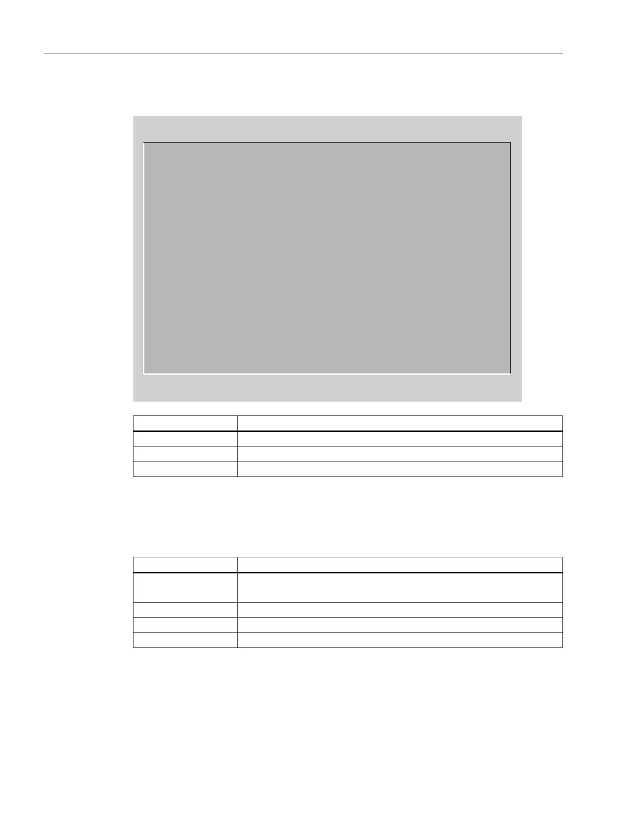
The structure of these messages is shown below:
Thin Client Boot loader
V04.50.11.00
IP address
<1/F1> diagnosis window
You can see the current boot phase in the third line. Below that you are told whether you can
call up information via <F1> if a fault occurs.
Diagnostics options during booting
In the following cases, the diagnostics window is displayed and booting of the TCU is
interrupted:
● When the <1 / F1> function is selected during booting
● When a warning message is displayed
● When a fault occurs
Note
You can select the <1 / F1> to <F8> functions shown below using the horizontal softkeys
on the OP. For example, to select <F7>, press the horizontal softkey 7.
Press the appropriate key <1> for <F1> at an HT8.
General information and networking
Manual, 03/2016, 6FC5397-1AP40-5BA3
93
Networking
5.4 Service and diagnostics
Calling up the diagnostics window with <1 / F1>
7hin Client Boot loader
V04.05.11.00
Boot progress:
BIOS
V03.04.00.00
MAC address
08:06:00:F1:F7:F8
Hardware ID
7.7.0.0
Network link
1000MB, full duplex
IP address
192.168.214.1
Netmask
255.255.255.0
Boot server
192.168.214.1
Image metadata
98 bytes
Image version
V04.50.11.00
Linux image (linux.bin)
3295436 bytes
Booting
ready
<1/F1>details
<7/F7>continue
<8/F8>reboot
Key / text
Meaning
F1 details
Display detailed information
F7 continue
Continue booting of the TCU
F8 reboot
Restart the TCU
Press <1 / F1> to continue
If you select function <F1> in the diagnostics window, the, detailed diagnostic information is
output.
Key / text
Meaning
F1 ... F6
Navigate within the window
(alternatively, the relevant keys on the OP can be used).
F7 +
Display more information
F8 -
Display less information
F9 back
Return to diagnostics window
General information and networking
94
Manual, 03/2016, 6FC5397-1AP40-5BA3
Index
B
H
Backup battery
Heat dissipation
Connection conditions, 19
Means of heat dissipation, 21
Boot server, 88
HT 8
Calibrate, 65
Rotary coding switch, 63
C
Calibrate touch panel
I
HT 8, 65
TCU, 66
IP address
Calibrate Touch Panel, 70
PG, 89
CompactFlash Card, 46
Company network, 44
Configuration file
M
config.ini, 58, 70
Membrane connectors
tcu.ini, 73
Connection conditions, 41
Connecting a PG, 89
Messages during TCU boot up, 93
Connection conditions
Backup battery, 19
EMC measures, 15
N
Membrane connectors, 41
Protective separation, 15
Network topology, 83
User interface, 15
O
D
Operator components
DCK (Direct Control Keys), 63
Overview, 13
DHCP client, 47
Overview
DHCP server, 47
Operator components, 13
Direct control keys, 63
SINUMERIK 840D sl, 12
DNS (Domain Name System), 45
P
E
Potential equalization, 16
EMC measures, 17
Protective separation
Connection conditions, 15
Connection conditions, 15
Ethernet connection, 83
Ethernet interface, 83
R
Replacement TCU, 64
F
Factory default settings, 47
Faults when booting, 93
S
Signal cables, 16
General information and networking
Manual, 03/2016, 6FC5397-1AP40-5BA3
95
Index
SIMATIC Thin Client, 67
SINUMERIK 840D sl
System overview, 12
SINUMERIK DHCP client, 47
SINUMERIK DHCP server, 48
SINUMERIK mode, 70
Star structure, 43
Start bar, 68
Switchover disable, 80
System
Boot behavior, 45
System network, 43
Configuring, 61
T
TCU
Assign index, 81
Assign names, 61
Boot-up messages, 93
Main menu, 50
Settings, 61
Supplementary conditions, 46
Thin Client Unit, 46
TCU diagnostics, 93
U
User authorization, 46, 82
User interface
Connection conditions, 15
V
Validity Manual, 43
General information and networking
96
Manual, 03/2016, 6FC5397-1AP40-5BA3
1
Operator panel front: OP 08T
Operator panel front: OP 010
2
Operator panel front: OP
3
010S
SINUMERIK
Operator panel front: OP
4
010C
SINUMERIK 840D sl
Operator panels
5
Operator panel front: OP 012
Operator panel front: OP 015
6
Manual
Operator panel front: OP
7
015A
Operator panel front: OP
8
015AT
Operator panel front: TP
9
015A
Operator panel front: TP
10
015AT
Operator panel front: OP 015
11
black
12
Operator panel front: OP 019
Operator panel front: OP 019
13
black
14
Direct control key module
Valid for: SINUMERIK 840D sl / 840DE sl control
15
PCU 50.5
16
TCU x0.2
03/2016
6FC5397-1AP40-5BA3
Table of contents
1
Operator panel front: OP 08T
11
1.1
Description
11
1.2
Control and display elements
12
1.2.1
View
12
1.2.2
Keyboard
13
1.2.3
Screen saver
14
1.3
Interfaces
15
1.4
Installation
16
1.5
Technical data
18
1.6
Spare parts
18
1.7
Accessories
19
1.7.1
Overview
19
1.7.2
Labeling the slide-in labels
19
1.7.3
Printing the slide-in labels
24
2
Operator panel front: OP 010
27
2.1
Description
27
2.2
Operator control and display elements
28
2.2.1
View
28
2.2.2
Keyboard
29
2.2.3
Screen saver
30
2.3
Interfaces
31
2.4
Installation
33
2.4.1
Preparation for mounting
33
2.4.2
Assembling an OP 010 and a PCU
34
2.4.3
Mounting on the mounting wall
35
2.4.4
Softkey labeling
35
2.5
Technical data
36
2.6
Spare parts
36
2.6.1
Overview
36
2.6.2
Replacement
38
3
Operator panel front: OP 010S
43
3.1
Description
43
3.2
Operating and display elements
44
3.2.1
View
44
3.2.2
Keyboard
44
3.2.3
Screen saver
45
3.3
Interfaces
45
Operator panels
Manual, 03/2016, 6FC5397-1AP40-5BA3
3
Table of contents
3.4
Mounting
46
3.4.1
Preparation for mounting
46
3.4.2
Mounting on the mounting wall
48
3.4.3
Assembling an OP 010S and a PCU
49
3.5
Technical data
49
3.6
Spare parts
50
3.6.1
Overview
50
3.6.2
Replacement
50
4
Operator panel front: OP 010C
51
4.1
Description
51
4.2
Operating and display elements
52
4.2.1
View
52
4.2.2
Keyboard
53
4.2.3
Screen saver
54
4.3
Interfaces
55
4.4
Mounting
57
4.4.1
Preparation for mounting
57
4.4.2
Assembling an OP 010C and a PCU
58
4.4.3
Mounting on the mounting wall
59
4.5
Technical data
59
4.6
Spare parts
60
4.6.1
Overview
60
5
Operator panel front: OP 012
61
5.1
Description
61
5.2
Operator control and display elements
62
5.2.1
View
62
5.2.2
Keyboard
63
5.2.3
Screen saver
64
5.3
Interfaces
64
5.4
Installation
66
5.4.1
Preparation for mounting
66
5.4.2
Assembling an OP 012 and a PCU
68
5.4.3
Mounting on the mounting wall
71
5.4.4
Softkey labeling
72
5.5
Technical data
72
5.6
Spare parts
73
5.6.1
Overview
73
5.6.2
Replacement
75
6
Operator panel front: OP 015
79
6.1
Description
79
6.2
Operating and display elements
80
6.2.1
View
80
Operator panels
4
Manual, 03/2016, 6FC5397-1AP40-5BA3
Table of contents
6.2.2
Keyboard
80
6.2.3
Screen saver
81
6.3
Interfaces
81
6.4
Mounting
82
6.4.1
Preparation for mounting
82
6.4.2
Assembling an OP 015 and a PCU
84
6.4.3
Mounting on the mounting wall
85
6.5
Technical data
85
6.6
Spare parts
86
6.6.1
Overview
86
6.6.2
Replacement
87
7
Operator panel front: OP 015A
91
7.1
Description
91
7.2
Operating and display elements
92
7.2.1
View
92
7.2.2
Keyboard
93
7.2.3
Screen saver
94
7.3
Interfaces
94
7.4
Mounting
96
7.4.1
Preparation for mounting
96
7.4.2
Assembling an OP 015A and a PCU
96
7.4.3
Mounting on the mounting wall
99
7.4.4
Softkey labeling
100
7.5
Technical specifications
101
7.6
Spare parts
102
7.6.1
Overview
102
7.6.2
Replacement
104
8
Operator panel front: OP 015AT
111
8.1
Description
111
8.2
Operator controls and indicators
112
8.2.1
View
112
8.2.2
Keyboard
113
8.2.3
Screen saver
114
8.3
Interfaces
115
8.4
Installation
116
8.4.1
Mounting
116
8.4.2
Softkey labeling
117
8.5
Technical data
118
8.6
Replacement parts
119
8.6.1
Overview
119
8.6.2
Replacement
120
Operator panels
Manual, 03/2016, 6FC5397-1AP40-5BA3
5
Table of contents
9
Operator panel front: TP 015A
127
9.1
Description
127
9.2
Operating and display elements
128
9.2.1
View
128
9.2.2
Operation
129
9.2.3
Keyboard
129
9.2.4
Screen saver
131
9.3
interfaces
131
9.4
Mounting
132
9.4.1
Preparation for mounting
132
9.4.2
Assembling TP 015A and PCU
133
9.4.3
Mounting on the mounting wall
133
9.4.4
Touchscreen calibration
134
9.4.5
Softkey labeling
135
9.5
Technical specifications
135
9.6
Spare parts
136
9.6.1
Overview
136
9.6.2
Replacement
138
10
Operator panel front: TP 015AT
147
10.1
Description
147
10.2
Operator controls and indicators
148
10.2.1
View
148
10.2.2
Operation
149
10.2.3
Keyboard
149
10.2.4
Screen saver
151
10.3
Interfaces
151
10.4
Installation
153
10.4.1
Mounting
153
10.4.2
Touchscreen calibration
154
10.4.3
Softkey labeling
154
10.5
Technical data
155
10.6
Replacement parts
156
10.6.1
Overview
156
10.6.2
Replacement
157
11
Operator panel front: OP 015 black
163
11.1
Description
163
11.2
Operator control and display elements
164
11.2.1
View
164
11.2.2
Operation
165
11.2.3
Keyboard
167
11.2.4
Screen saver
168
11.3
Interfaces
168
11.4
Assembly
170
Operator panels
6
Manual, 03/2016, 6FC5397-1AP40-5BA3
Table of contents
11.4.1
Touchscreen calibration
174
11.5
Technical data
174
11.6
Spare parts/accessories
175
12
Operator panel front: OP 019
177
12.1
Description
177
12.2
Operator control and display elements
179
12.2.1
View
179
12.2.2
Keyboard
180
12.2.3
Softkeys
181
12.2.4
Screen saver
181
12.3
Interfaces
182
12.4
Mounting
184
12.4.1
Preparation for mounting
184
12.4.2
Assembling an OP 019 and a PCU
186
12.4.3
Assembling an OP 019 and a TCU
187
12.4.4
Mounting on the mounting wall
188
12.5
Technical data
189
13
Operator panel front: OP 019 black
191
13.1
Description
191
13.2
Operator control and display elements
192
13.2.1
View
192
13.2.2
Operation
193
13.2.3
Screen saver
194
13.3
Interfaces
195
13.4
Installation
197
13.5
Technical specifications
201
13.6
Spare Parts/Accessories
202
14
Direct control key module
203
14.1
Description
203
14.2
Operating and display elements
203
14.3
Interfaces
204
14.4
Mounting
205
14.4.1
Overview
205
14.4.2
Combination with OP 012
206
14.4.3
Combination with OP 015A / TP 015A
208
14.5
Technical data
210
15
PCU 50.5
213
15.1
Description
213
15.2
Operator control and display elements
216
15.2.1
On/off switch
216
Operator panels
Manual, 03/2016, 6FC5397-1AP40-5BA3
7
Table of contents
15.2.2
Service module
217
15.3
Interfaces
219
15.3.1
External interfaces
219
15.3.2
Internal interfaces
222
15.3.2.1
Connector assignment of motherboard
222
15.3.2.2
Connector assignment of bus board
226
15.4
Mounting
231
15.4.1
Preparation for mounting
231
15.4.2
Assembly of PCU and operator panel front (standard mounting)
234
15.4.3
Flat mounting
234
15.4.4
Upright mounting
236
15.4.5
Notes on installation
239
15.4.6
Connecting Ethernet/USB strain relief
240
15.4.7
Relocating the service module
241
15.5
Connecting
242
15.5.1
Power supply
242
15.5.2
Equipotential
243
15.5.3
I/O devices
244
15.6
Commissioning
245
15.6.1
BIOS
245
15.6.1.1
BIOS powering up
245
15.6.1.2
Changing the BIOS settings
247
15.6.2
System start
248
15.6.3
Switching off / reset
248
15.6.4
Touchscreen calibration
249
15.6.5
Operation with an S7-CPU (without NCU)
252
15.6.6
Configuring the 'fb9_proxy.ini' file
253
15.7
Alarm, error and system messages
257
15.7.1
Boot error messages
257
15.7.2
BIOS beep codes
258
15.7.3
Status codes of the diagnostics display during the system power up
261
15.7.4
Status codes of the diagnostics display during operation
262
15.7.5
Status codes of the diagnostics display during the shutdown process
262
15.8
Technical data
262
15.8.1
PCU 50.5
262
15.8.2
Calculating the power
264
15.8.3
Power failure detection
264
15.9
Spare parts
265
15.9.1
Overview
265
15.9.2
Replace
265
15.9.2.1
SSD module
266
15.9.2.2
Power supply
268
15.9.2.3
Power supply fan
269
15.9.2.4
Device fan
270
15.9.2.5
Backup battery
271
15.10
Accessories
274
15.10.1
Overview
274
15.10.2
Installing and removing expansion modules
274
Operator panels
8
Manual, 03/2016, 6FC5397-1AP40-5BA3
Table of contents
15.10.2.1
Memory expansion
274
15.10.2.2
PCI cards
276
15.10.2.3
CompactFlash card
278
16
TCU x0.2
281
16.1
Description
281
16.1.1
Overview
281
16.1.2
Configurations
282
16.2
Interfaces
283
16.3
Mounting the TCU on the operator panel front
285
16.4
Technical data
289
16.5
Accessories
289
Index
291
Operator panels
Manual, 03/2016, 6FC5397-1AP40-5BA3
9
Table of contents
Operator panels
10
Manual, 03/2016, 6FC5397-1AP40-5BA3
Operator panel front: OP 08T
1
1.1
Description
The compact SINUMERIK OP 08T operator panel front enables a spatially distributed
configuration of the operator panel front and control.
The OP 08T operator panel front has a membrane keyboard with 79 keys (layout similar to
SINUMERIK CNC full keyboard KB 310C) as well as 2x8 horizontal and 2x8 vertical soft keys.
The distance to the operator panel fronts is determined by the maximum distance of two
network nodes / access points.
The OP 08T operator panel front is connected to the PCU / NCU via the Ethernet as thin client
in its own subnet (via DHCP server to PCU / NCU).
The mixed operation with an operator panel front is possible directly at the PCU.
The operator panel front is secured from the rear using special clamps supplied with the panel.
Validity
The description below applies to the OP 08T operator panel front
Article number: 6FC5203-0AF04-1BA1.
Features
● Ethernet
● 3x USB for connecting the mouse, keyboard and USB flash drive
(1x front / 2x rear)
●
7.5" TFT flat screen with VGA resolution 640x480 pixels
● Membrane keyboard with alphabetic, numeric, cursor, and control keypad
● Softkeys / direct keys
-
2 x 8 horizontal rows of keys with softkey function
–
2 x 8 vertical rows of keys with softkey and direct key function
● Shift key for switchover to the second key level (not for switching over the letters, since
they are uppercase only)
● Limited mounting depth
● Panel cutout (W x H): 285 x 304 mm
● Degree of protection IP65
● Attachment: Tension jacks at the rear
Operator panels
Manual, 03/2016, 6FC5397-1AP40-5BA3
11
Operator panel front: OP 08T
1.2 Control and display elements
1.2
Control and display elements
1.2.1
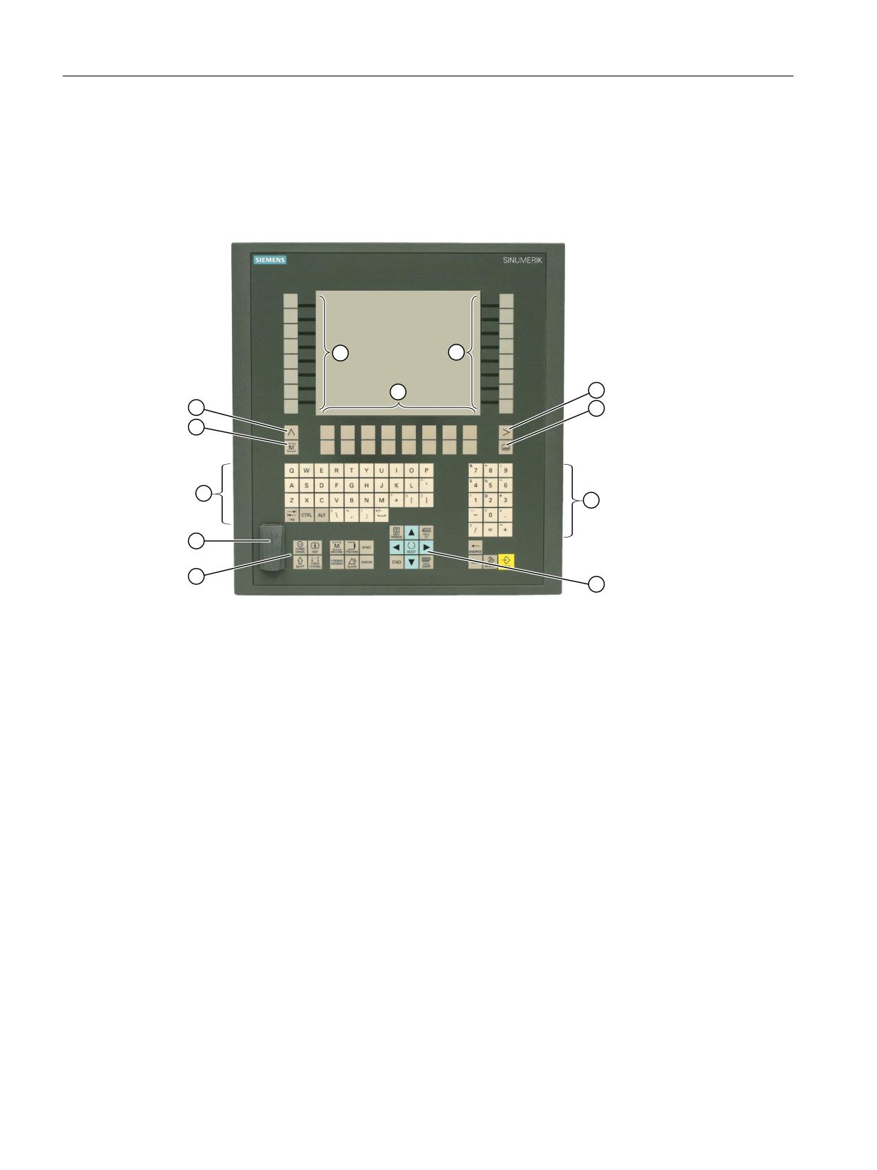
View
① Menu forward key
② Menu select key
③ Numeric pad
④ Cursor pad
⑤ Control pad
⑥ Interface USB 1.1 Full Speed
⑦ Alphabetic pad
⑧ Machine area button
⑨ Menu back key
⑩ Vertical softkeys (direct keys)
⑪ Horizontal softkeys
Image 1-1
View of OP 08T operator panel front
Operator panels
12
Manual, 03/2016, 6FC5397-1AP40-5BA3
Operator panel front: OP 08T
1.2 Control and display elements
1.2.2
Keyboard
Keyboard
Several keys and keypads are installed on the operator panel front:
● The alphabetic block contains the letters A - Z (QWERTY), the space character and special
characters.
● The numeric block contains the digits 0 - 9, and the characters "-", "/", "=", "+" and ".".
● The cursor key group is used to navigate on the screen.
● The control key group includes special functions.
● The softkeys call up functions that are available on the screen via a menu bar.
● The "Menu back" key switches back to the higher-level horizontal menu.
● The "Menu forward" key advances in the extended horizontal softkey bar.
● The "Menu select" key calls the main menu to select the operating area.
● The "Machine area" key selects the "Machine" operating area.
Switching between upper and lower case
Upper case is always activated as standard.
To switch to lower case, keep the SHIFT key pressed.
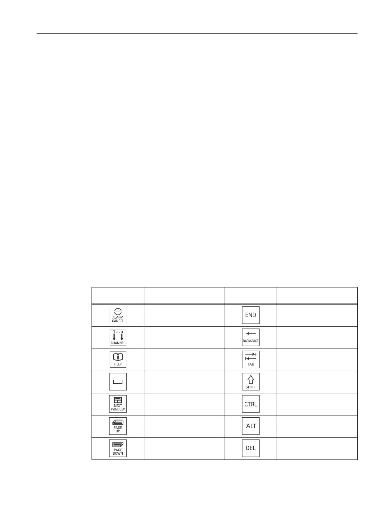
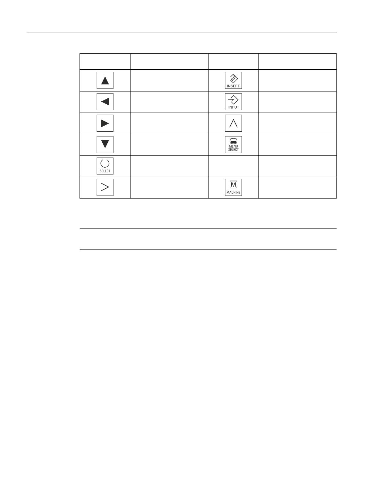
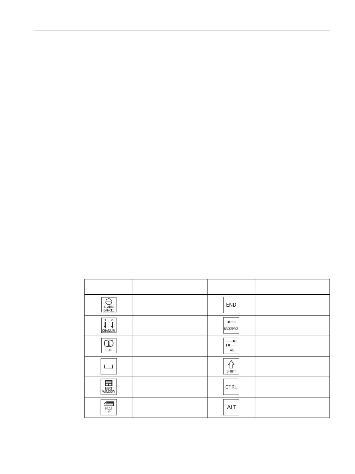
Overview of the key symbols
The key symbols used on the operator panel front are shown below along with the
corresponding function keys on the PC keyboard.
Key
Function corresponds to the
Key
Function corresponds to the
PC key function
PC key function
Esc
End
F11
Backspace
F12
Tab
Space
(only intended for internal key-
board changeover)
Home
Ctrl key
Page up
Alt key
Page down
Delete
Operator panels
Manual, 03/2016, 6FC5397-1AP40-5BA3
13
Operator panel front: OP 08T
1.2 Control and display elements
Key
Function corresponds to the
Key
Function corresponds to the
PC key function
PC key function
Cursor up
Insert
Cursor left
Enter
Cursor right
F9
Cursor down
F10
5 (in numeric key group)
A, ..., Z
<Shift> A, ..., Z
<Shift> F9
<Shift> F10
Display
Note
Pixel error according to DIN EN ISO 13406-2 Class II.
1.2.3
Screen saver
If a screen with high contrast is displayed unchanged for longer than an hour, then the
screensaver must be activated in order to protect the TFT display against so-called "burning
in" of the last displayed screen.
The time can be adapted individually. Further information can be found at:
Commissioning of Basic Software and Operating Software, SINUMERIK Operate (IM9)
Operator panels
14
Manual, 03/2016, 6FC5397-1AP40-5BA3
Operator panel front: OP 08T
1.3 Interfaces
1.3
Interfaces
Front
USB 1.1 Full Speed (socket, type A) for connecting an external keyboard, mouse and USB
flash drive (see Image 1-1 View of OP 08T operator panel front (Page 12)).
Note
Note that the electromagnetic compatibility of commercially available peripheral devices
operated via the USB interface is usually rated for office use only.
For industrial use, components with a higher degree of certification are recommended.
Rear
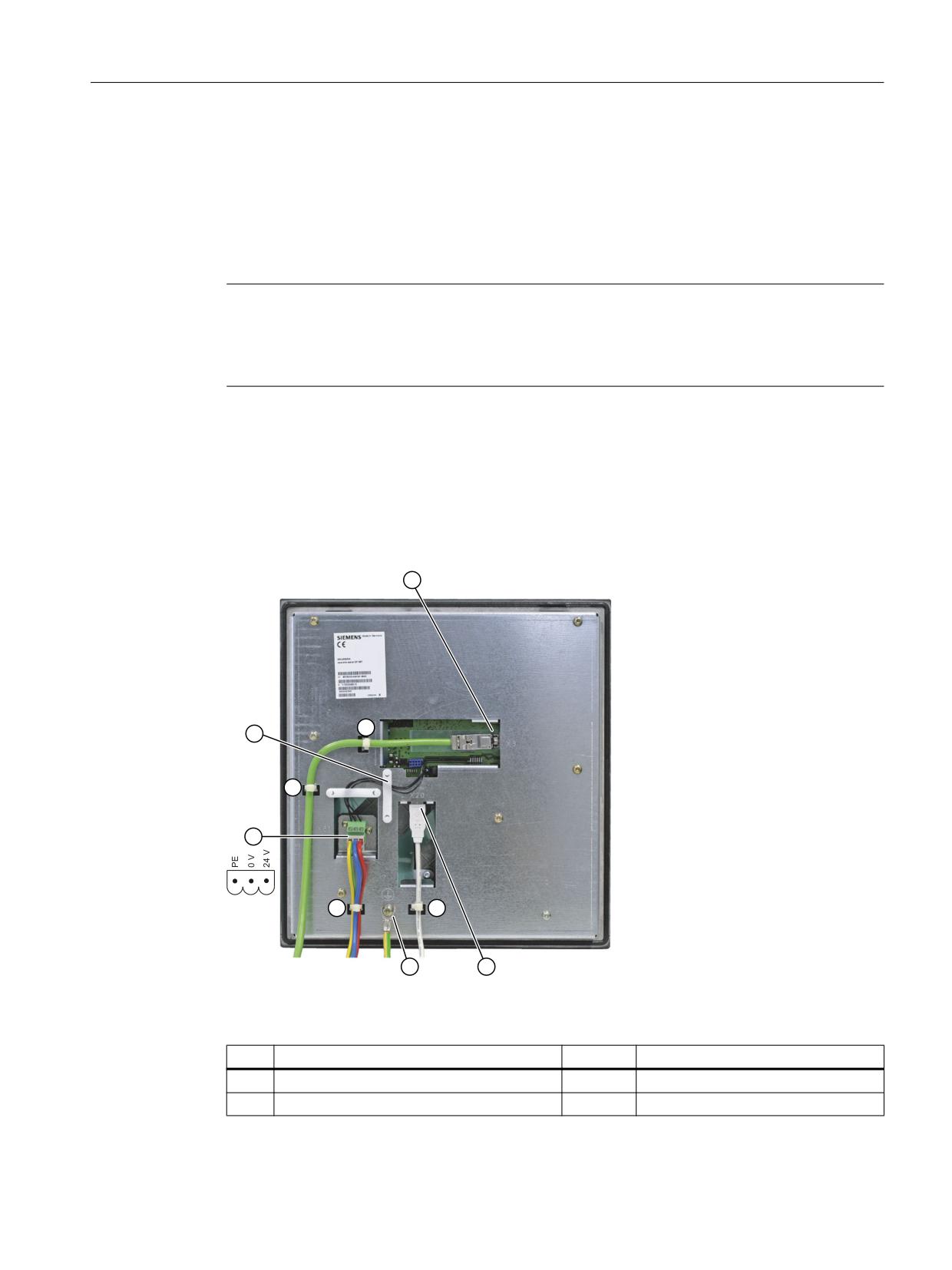
● Ethernet 10/100/1000 Mbit/s (without crossover function)
●
2 x USB 2.0 Hi-Speed
●
24 VDC power supply
Image 1-2
Rear view of OP 08T operator panel front
Designation
Type
①
Strain relief for connecting cables
②
Ethernet interface
X3
8-pin RJ45 socket
Operator panels
Manual, 03/2016, 6FC5397-1AP40-5BA3
15
Operator panel front: OP 08T
1.4 Installation
Designation
Type
③
USB interfaces
X203/
Type A socket
X204
④
Ground terminal
M5 screw (for screw connection with
cable lug)
⑤
Power supply
X81
3-pin terminal block
⑥
Cable clamp
Pin assignment
For the pin assignment of the interfaces, see "General information and networking" →
"Connecting".
1.4
Installation
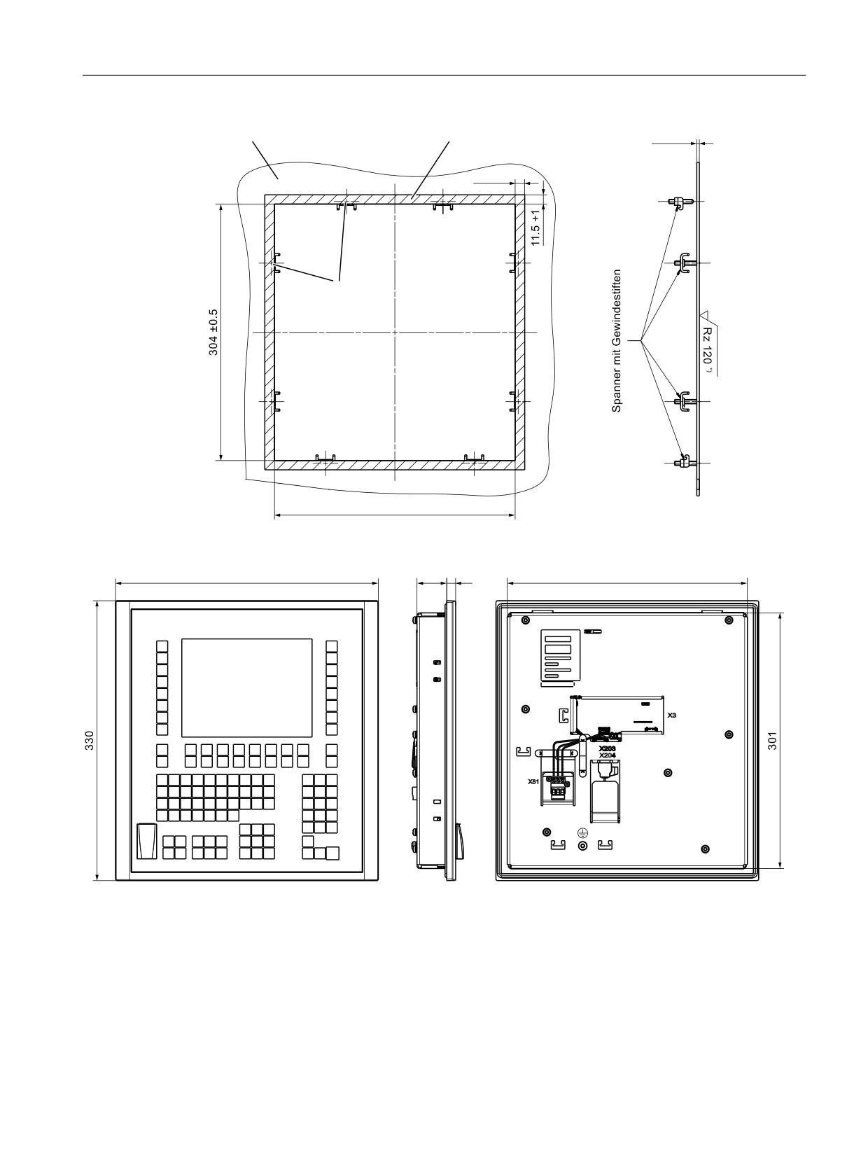
The OP 08T operator panel front is fixed in a rectangular section with clamps. For this reason,
bore holes or screw holes are not needed. The tightening torque of the clamp set screws must
not exceed 0.5 Nm.
Table 1-1
Dimensions of the mounting opening OP 08T
Width (mm)
Height (mm)
Mounting depth (mm)
285
304
35 *)
*) Plus 10 mm cable connector and ventilation clearance
Operator panels
16
Manual, 03/2016, 6FC5397-1AP40-5BA3
Operator panel front: OP 08T
1.4 Installation
0RQWDJHZDQG
'LFKWXQJVEHUHLFK
'UXFNSXQNWH
I¾U 6SDQQHU
s
LP 'LFKWXQJVEHUHLFK
Image 1-3
Dimension sheet for installing the OP 08T operator panel front
Image 1-4
Dimensions of the OP 08T
Operator panels
Manual, 03/2016, 6FC5397-1AP40-5BA3
17
Operator panel front: OP 08T
1.6 Spare parts
1.5
Technical data
Safety
Safety class
III; PELV according to EN 50178
Degree of protection accord-
Front side IP65
ing to EN 60529
Rear side IP00
Approvals
CE / cULus
Electrical data
Supply voltage
24 V DC
Power consumption
Max. approx. 15 W
Mechanical data
Dimensions
Width: 310 mm
Height: 330 mm
Depth: 46 mm
Weight
approx. 2.9 kg (without tension jack)
Tightening torques, max.
Tension jacks: 0.4 - 0.5 Nm
M5 grounding screw: 3 Nm
Display
Size / resolution
7.5" TFT / 640x480 pixel (VGA)
Note
Information about the climatic and mechanical environmental conditions is contained in the
associated section under:
"General notes and interconnection" → "Operational planning".
1.6
Spare parts
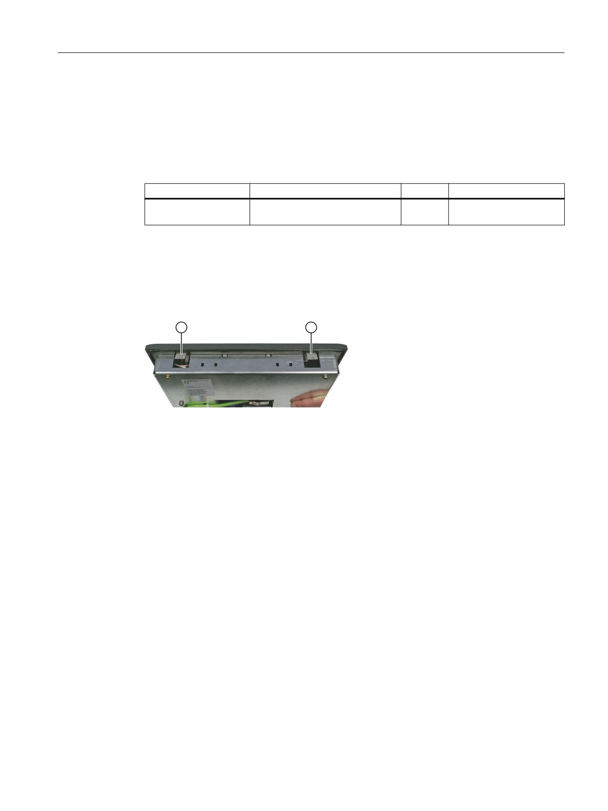
The following components are available as spare parts for the OP 08T operator panel:
Spare part
Article number
Remark
Tension jacks
6FC5248-0AF14-0AA0
Set of 9
(for supplementary components with 2.5 mm profile,
length: 20 mm)
Caps for the USB port
6FC5248-0AF05-0BA0
Set of 5
Operator panels
18
Manual, 03/2016, 6FC5397-1AP40-5BA3
Operator panel front: OP 08T
1.7 Accessories
1.7
Accessories
1.7.1
Overview
The following accessories are available for the OP 08T operator panel front:
Component
Description
Quantity
Article number
Slide-in labels
Slide-in labels, inscribable
1
6FC5248-0AF04-1BA0
(3 films, DIN A4)
1.7.2
Labeling the slide-in labels
The OP 08T operator panel front is delivered ex-factory with two vertical slide-in labels
(unprinted / backg1round color: grayed-out).
① Teil 1
② Teil 2
Image 1-5
Position of the vertical OP 08T slide-in labels
Upon request, a spare part packet with three blank films can be ordered, in order to print the
slide-in labels with the key symbols.
Operator panels
Manual, 03/2016, 6FC5397-1AP40-5BA3
19
Operator panel front: OP 08T
1.7 Accessories
Files for printing the blank film
① Print direction
Image 1-6
Blank film OP 08T
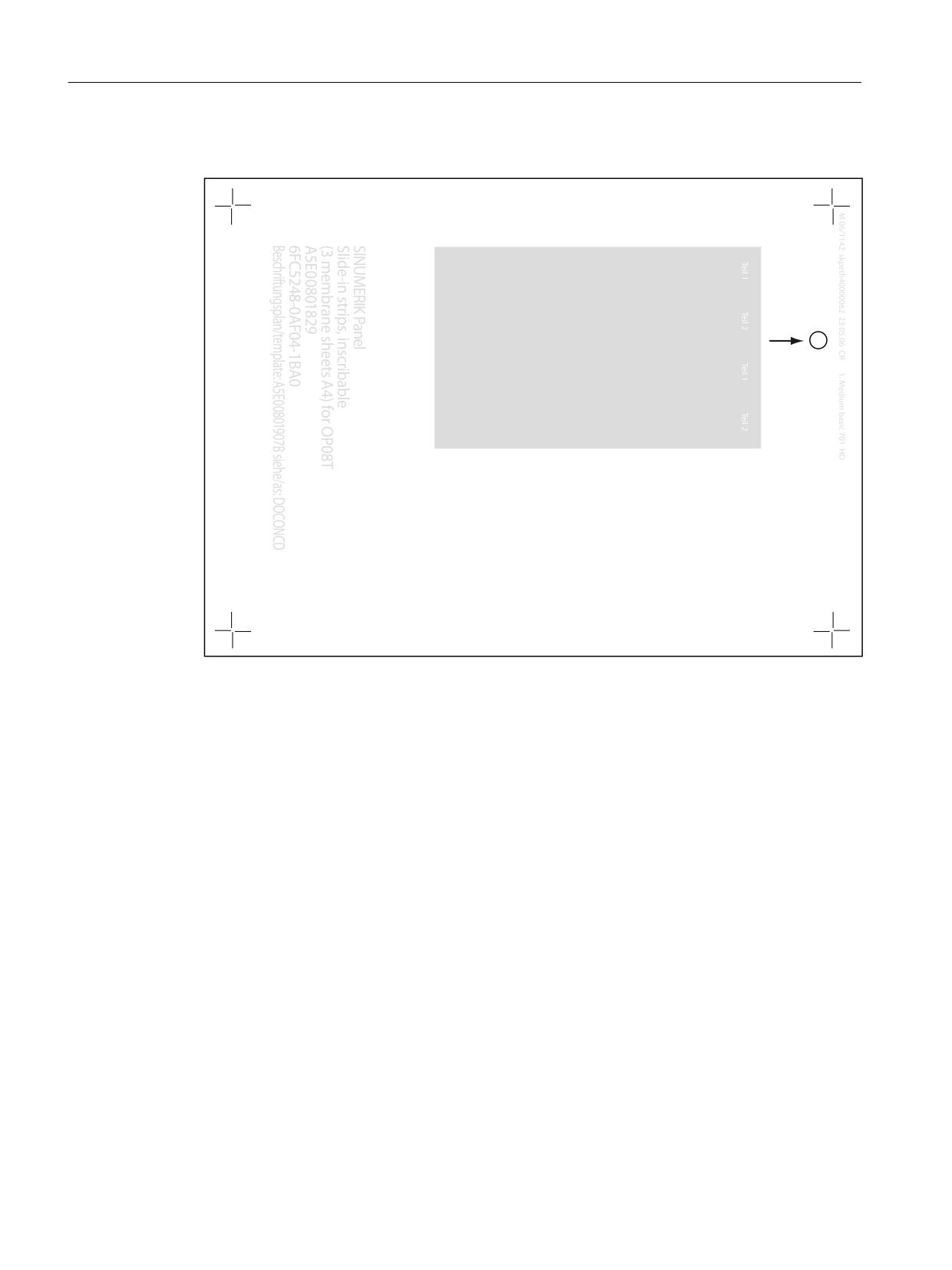
The DOConCD or Catalog NC 61/62 (CD enclosed) contains two files for printing the blank
films:
● Template_OP08T_13.doc
● Symbols_OP08T_13.doc
The file "Template_OP08T_13.doc" is a template for the exact positioning of the symbols on
the printable film.
Operator panels
20
Manual, 03/2016, 6FC5397-1AP40-5BA3
Operator panel front: OP 08T
1.7 Accessories
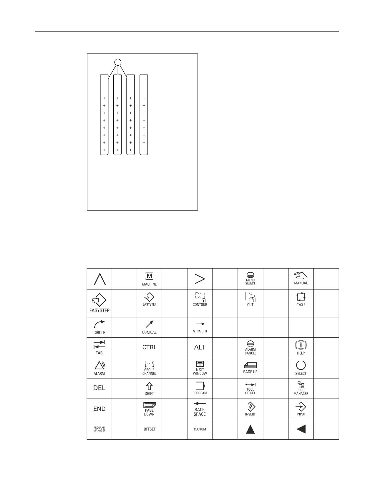
① Outer edges
Image 1-7
Template_OP08T_13.doc (blank template for film)
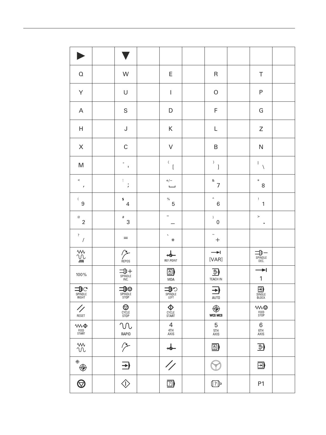
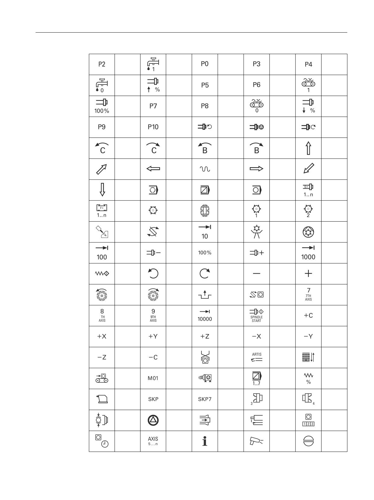
The "Symbols_OP08T_13.doc" file contains a wide range of key symbols:
Table 1-2
Key symbols OP 08T
5000
5001
5002
5003
5068
5069
5070
5071
5072
5073
5074
5075
5076
6000
6001
6002
6003
6004
6005
6006
6007
6008
6009
6010
6011
6012
6013
6014
6015
6016
6017
6018
6019
6069
6070
6071
6072
6073
Operator panels
Manual, 03/2016, 6FC5397-1AP40-5BA3
21
Operator panel front: OP 08T
1.7 Accessories
6074
6075
6020
6021
6022
6023
6024
6025
6026
6027
6028
6029
6030
6031
6032
6033
6034
6035
6036
6037
6038
6040
6041
6042
6043
6044
6045
6046
6039
6048
6049
6050
6051
6052
6053
6054
6055
6056
6057
6058
6059
6060
6061
6062
6063
6064
6065
6066
6067
7133
7134
7001
7002
7003
7004
7005
7006
7007
7008
7009
7010
7012
7013
7014
7015
7017
7018
7020
7021
7024
7025
7026
7027
7029
7030
7031
7040
7041
7042
7043
7044
7045
7046
7047
7048
7049
7051
7052
7053
7054
7055
Operator panels
22
Manual, 03/2016, 6FC5397-1AP40-5BA3
Operator panel front: OP 08T
1.7 Accessories
7056
7057
7058
7059
7060
7061
7062
7063
7064
7065
7066
7067
7068
7069
7070
7071
7072
7073
7074
7075
7076
7077
7078
7086
7079
7080
7081
7082
7083
7084
7085
7087
7088
7089
7090
7091
7092
7093
7094
7095
7096
7099
7100
7101
7102
7103
7104
7105
7106
7107
7108
7109
7110
7111
7112
7113
7114
7115
7116
7120
7121
7122
7123
7124
7125
7126
7127
7128
7129
7130
7131
7132
7135
7136
7137
7138
7139
7140
7141
7142
7143
7144
7145
7146
7147
7148
7149
7150
7151
7152
7153
7154
7155
7156
7157
Operator panels
Manual, 03/2016, 6FC5397-1AP40-5BA3
23

Operator panel front: OP 08T
1.7 Accessories
7158
7159
7160
7161
7162
7163
7164
Preparing slide-in labels
Inserting symbols
1. Open the files "Template_OP08T_13.doc" and "Symbols_OP08T_13.doc" in MS Word.
2. Select a key symbol from the file "Symbols_OP08T_13.doc" by left-clicking.
3. Copy the desired key symbol to the clipboard via "Edit" → "Copy" or "Ctrl + C"
4. Return to the template file "Template_OP08T_13.doc"
5. Position the cursor before the insertion point in the desired table cell (in Fig.:
"Template_OP08T_13.doc the insertion point is displayed by "+").
6. Insert the key symbol via "Edit" → "Paste" or "Ctrl + V".
7. Repeat steps 2. to 6. until you have inserted all the key symbols.
Inserting characters/text
1. Open the "Template_OP08T_13.doc" files in the MS Word text processing program.
2. Set the "Arial" font to format characters.
(This font is comparable to the "Univers S57" font, used by Siemens for the key labeling.)
3. Position the cursor in the desired table cell and enter characters/text.
1.7.3
Printing the slide-in labels
Printing the slide-in labels
1. Place the blank film in the printing direction in the slot of your laser printer (see figure Image
1-6 Blank film OP 08T (Page 20)).
2. Select "film" as the printable medium if your printer allows this setting.
3. Start the printing process using MS Word.
Note
For labeling the slide-in labels, HP Color Laser Jet film C2936A is used.
Make a test print on paper before you print on the film.
Allow the film to cool after printing so that the ink can dry.
4. Cut the slide-in labels out of the film along the edges (see Image 1-7
Template_OP08T_13.doc (blank template for film) (Page 21))..
5. Round off the corners of the slide-in labels approx. 3 mm to facilitate insertion.
Operator panels
24
Manual, 03/2016, 6FC5397-1AP40-5BA3
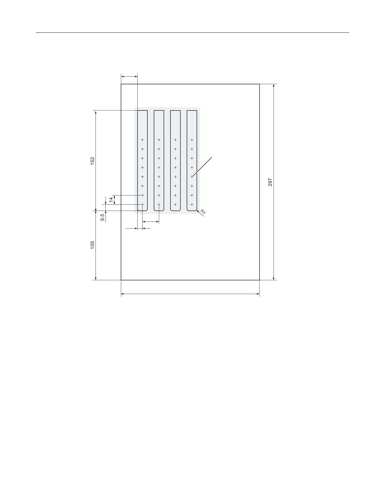
Operator panel front: OP 08T
1.7 Accessories
Dimension drawing
%ODQN ILOP ',1 $
7HLO
7HLO
7HLO
7HLO
&HQWHU RI WKH NH\
Image 1-8
Dimensions for vertical slide-in labels
Creating your own symbols
● Drawing in a vector program (e.g. Freehand, CorelDraw)
- Draw a 13 x 13 mm square, fill with the color white and give it an invisible border line.
- Place the symbol in the center of this square.
- Group the square and symbol together and add this group in the MS Word document
Template_OP08T_13.doc.
● Drawing in an image editing program (e.g. Photoshop, Paintshop Pro)
- Draw a square 13 x 13 mm (37 x 37 pixels), filled with the color white.
- Draw the symbol in the center of this square.
- Copy the symbol and the square together and add the group in the MS Word document
Template_OP08T_13.doc.
Operator panels
Manual, 03/2016, 6FC5397-1AP40-5BA3
25
Operator panel front: OP 08T
1.7 Accessories
Operator panels
26
Manual, 03/2016, 6FC5397-1AP40-5BA3
Operator panel front: OP 010
2
2.1
Description
The SINUMERIK OP 010 operator panel front has a 10.4" TFT color display with a resolution
of 640 x 480 pixels (VGA) and features a 62-key membrane keyboard (with 8 + 4 horizontal
softkeys and 8 vertical softkeys) that has been optimized for programming parts programs.
It is fixed from the rear using special clamps that are included in the delivery scope.
Validity
The description below applies to the OP 010 operator panel front.
Article number: 6FC5203-0AF00-0AA1
Features
●
19" mounting format, 7 HU (height units)
● Panel cutout (W x H): 450 x 290 mm
● Limited mounting depth
●
10.4" flat screen (color) with VGA resolution 640 x 480 pixels using TFT technology
● Membrane keyboard with alphabetic, numeric, cursor, control and hotkey key groups
● Softkeys: 8 + 4 horizontal and 8 vertical softkeys
● Shift key for switchover to the second key level (not for switching over the letters, since
they are uppercase only)
● Front USB interface
● Degree of protection IP65
● Attachment: Tension jacks at the rear
● Can be combined with PCU, TCU
Operator panels
Manual, 03/2016, 6FC5397-1AP40-5BA3
27
Operator panel front: OP 010
2.2 Operator control and display elements
2.2
Operator control and display elements
2.2.1
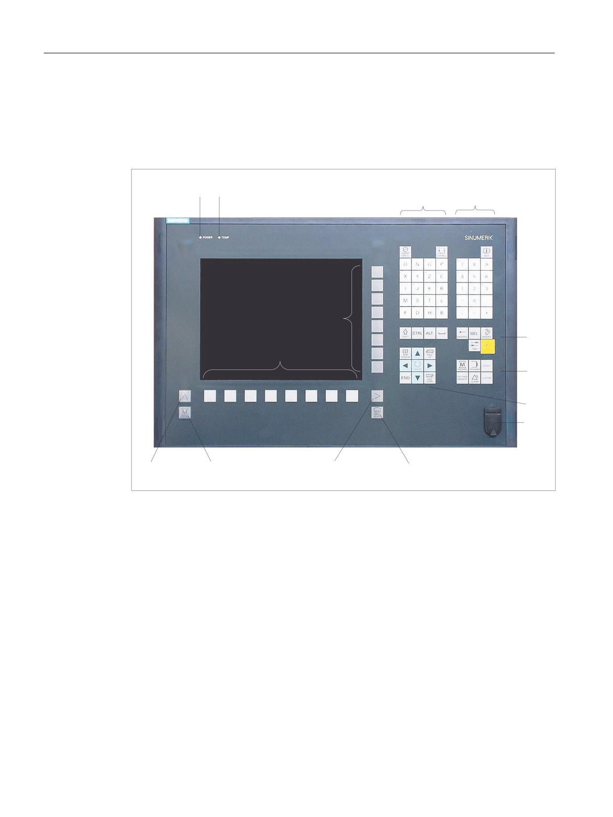
View
(5)
(5)
(1)
Status LED: POWER
(2)
Status LED: TEMP
Lit LEDs indicate increased wear.
(3)
Alphabetic key group
(4)
Numerical key group
(5)
Softkeys
(6)
Control key group
(7)
Hotkey group
(8)
Cursor key group
(9)
Front USB interface
(10)
Menu select key
(11)
Menu forward key
(12)
Machine area key
(13)
Menu back key
Image 2-1
View of OP 010 operator panel front
Operator panels
28
Manual, 03/2016, 6FC5397-1AP40-5BA3
Operator panel front: OP 010
2.2 Operator control and display elements
2.2.2
Keyboard
Keyboard
Several keys and keypads are arranged on the OP 010 operator panel front:
● The alphabetic key group contains the letters A, ..., Z on two levels, arranged in accordance
with programming requirements.
● The numeric block contains the digits 0 - 9, and the characters "-", "/", "=", "+" and ".".
● The control key group includes special functions.
● The hotkey group is used for the direct selection of operating areas.
● The cursor key group is used to navigate on the screen.
● The softkeys call up functions that are available on the screen via a menu bar.
● The "Menu back" key switches back to the higher-level horizontal menu.
● The "Menu forward" key advances in the extended horizontal softkey bar.
● The "Menu select" key calls the main menu to select the operating area.
● The "Machine area" key selects the "Machine" operating area.
Switching between upper and lower case
To toggle between upper and lower case letters, press the key combination Ctrl + Shift
Upper case is always activated as standard.
Overview of the key symbols
The key symbols used on the operator panel front are shown below along with the
corresponding function keys on the PC keyboard.
Key
Function corresponds to the
Key
Function corresponds to the
PC key function
PC key function
Esc
End
F11
Backspace
F12
Tab
Space
(only intended for internal key-
board changeover)
Home
Ctrl key
Page up
Alt key
Operator panels
Manual, 03/2016, 6FC5397-1AP40-5BA3
29
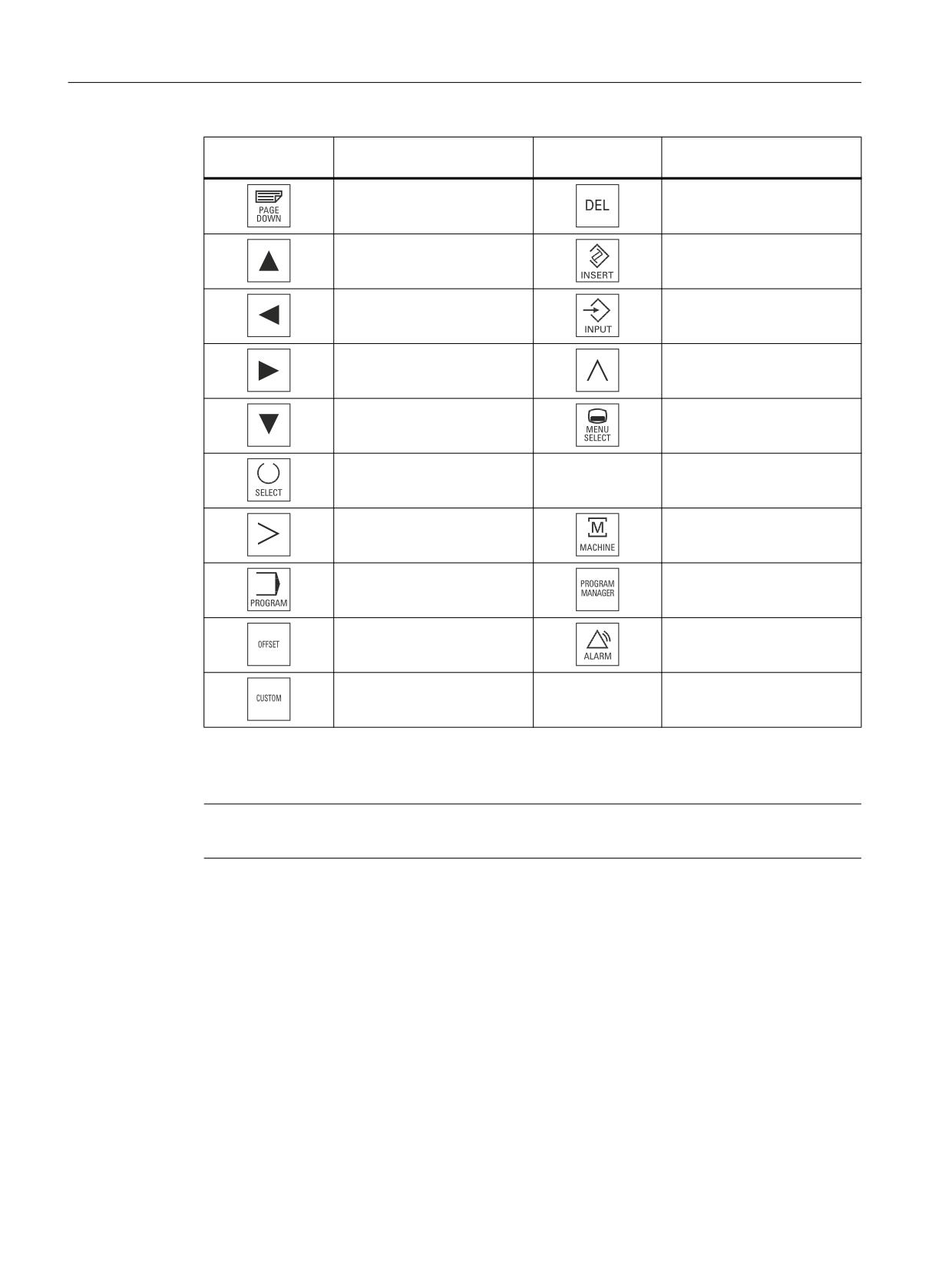
Operator panel front: OP 010
2.2 Operator control and display elements
Key
Function corresponds to the
Key
Function corresponds to the
PC key function
PC key function
Page down
Delete
Cursor up
Insert
Cursor left
Enter
Cursor right
F9
Cursor down
F10
5 (in numeric key group)
A, ..., Z
<Shift> A, ..., Z
<Shift> F9
<Shift> F10
Display
Note
Pixel error according to DIN EN ISO 13406-2 Class II.
2.2.3
Screen saver
If a screen with high contrast is displayed unchanged for longer than an hour, the screen must
be switched dark (screensaver) in order to protect the TFT display against so-called "freezing"
of the last displayed screen.
The time can be adapted individually. Further information can be found at:
IM9 SINUMERIK Operate Commissioning Manual
Operator panels
30
Manual, 03/2016, 6FC5397-1AP40-5BA3
Operator panel front: OP 010
2.3 Interfaces
2.3
Interfaces
This operator panel front has the following interfaces:
Front
USB 1.1 (type A) for connecting an external keyboard, mouse and USB FlashDrive (see View
of the operator panel front (Page 28)).
Note
Note that the electromagnetic compatibility of commercially available peripheral devices
operated via the USB interface is usually rated for office use only.
For industrial use, components with a higher degree of certification are recommended.
Operator panels
Manual, 03/2016, 6FC5397-1AP40-5BA3
31
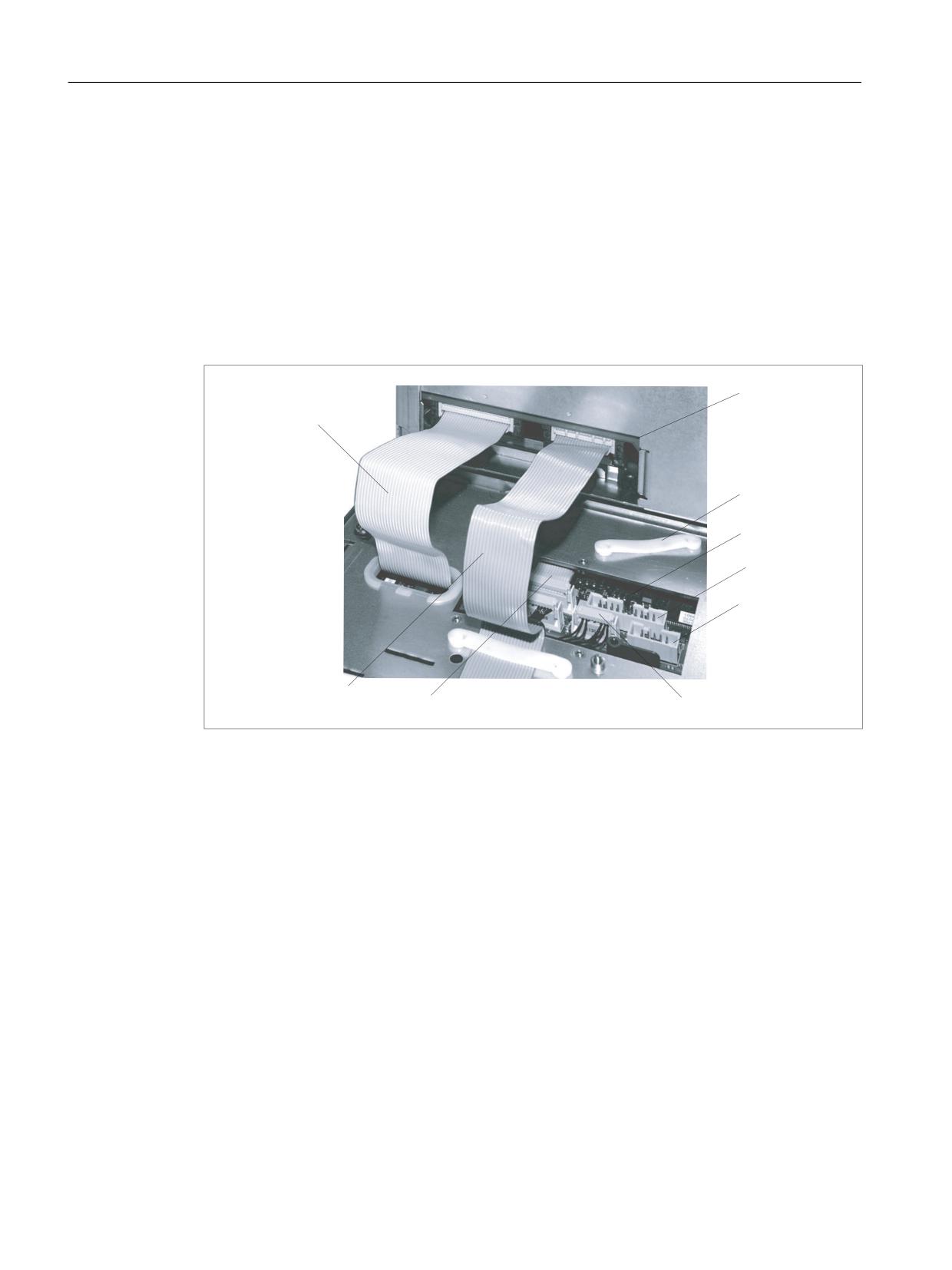
Operator panel front: OP 010
2.3 Interfaces
Rear side
● Two ribbon cables for connecting the PCU (see figure below):
- I/O USB cable K1 (ribbon cable):
All signals that are used for the display interface and the connection of operator panel
fronts
(e.g. supply voltages)
- Display cable K2
● Direct key interface X11 (under cover plate)
● Interface X12 - reserved (under cover plate)
(1)
I/O USB cable K1
(2)
PCU main board
(3)
Cable clamp for connecting the direct key module
(4)
Keyboard controller
(5)
Direct key interface X11
(6)
Interface X12 (reserved)
(7)
Connection X14 for backlight
(8)
Connection X1 for I/O USB cable K1
(9)
Display cable K2
Image 2-2
Connections on rear of housing Connections with PCU 50
Pin assignment
For more detailed information, see "General information and networking", Chapter:
"Connecting".
Operator panels
32
Manual, 03/2016, 6FC5397-1AP40-5BA3
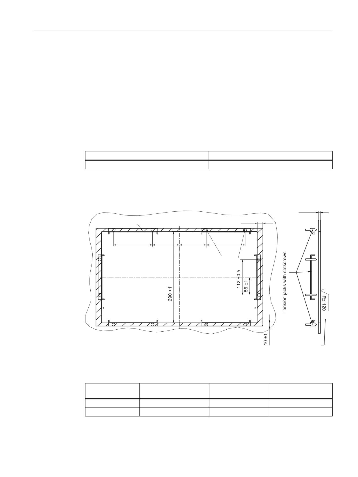
Operator panel front: OP 010
2.4 Installation
See also
View (Page 28)
2.4
Installation
2.4.1
Preparation for mounting
Table 2-1
Dimensions of the installation opening
Width (mm)
Height (mm)
450
290
Thanks to the tension jacks on the OP 010, drill-holes or screw holes are not needed.
This retaining method also enables the IP65 degree of protection (but only in conjunction with
a circumferential seal and when the protective USB cap is fitted).
6HDOLQJ DUHD
s
s
s
s
s
3UHVVXUH
SRLQWV
IRU WHQVLRQ
MDFNV
,Q WKH VHDOLQJ DUHD
Image 2-3
Dimension sheet for installing the OP 010 operator panel front
Table 2-2
Dimensions to be observed when installing
Mounting depth T3 + clear-
Opening depth T5
Protrusion P
ance (mm)
(mm)
(mm)
PCU 50.3 / 50.5
101 + 10
377
39
TCU x0.2
50 + 10
350
-12
Operator panels
Manual, 03/2016, 6FC5397-1AP40-5BA3
33
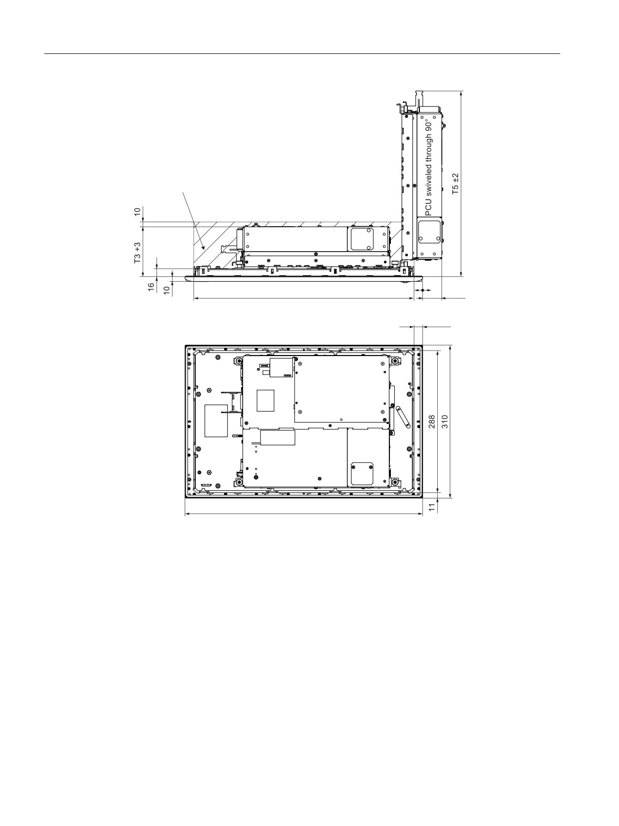
Operator panel front: OP 010
2.4 Installation
6SDFH IRU FDEOHV DQG YHQWLODWLRQ
3&8 LQ ILQDO SRVLWLRQ
s
s
s
Image 2-4
Dimension sheet for mounting the OP 010 with PCU
2.4.2
Assembling an OP 010 and a PCU
When combining an OP 010 and PCU, it is advisable to assemble them prior to installing them
in the assembly panel.
Procedure
To do this, proceed as described in Section: “OP 012”, Section: "Assembling the OP 012 and
PCU".
Operator panels
34
Manual, 03/2016, 6FC5397-1AP40-5BA3
Operator panel front: OP 010
2.4 Installation
2.4.3
Mounting on the mounting wall
The clearance at the rear of the PCU must be at least 10 mm in order to ensure that it is
adequately ventilated (see Image 2-3 Dimension sheet for installing the OP 010 operator panel
front (Page 33)).
For more detailed information, please refer to the relevant PCU sections and in "General
information and networking", Section: "Application planning", Section: "Climatic and
mechanical environmental conditions" → "Cooling".
NOTICE
Impermissible mounting positions can cause malfunctions
Observe the permissible mounting position: Deviating by up to 5º from the vertical.
This value can be further restricted by mounted components (PCU).
Procedure
1. Insert the assembled components (operator panel front and PCU) from the front into the
panel cutout (see Image 2-4 Dimension sheet for mounting the OP 010 with PCU
(Page 34)).
2. Secure the operator panel front in the panel cutout from the rear using the tension jacks by
tightening the setscrews (torque 0.4 - 0.5 Nm).
2.4.4
Softkey labeling
User-specific functions can be assigned to the vertical softkey bars. Printed labeling strips can
be used to label the vertical softkeys.
Blank labels are already installed on delivery.
DIN A4 films are available for making the strips (for the article number, see Chapter Spare
parts (Page 36)).
Note
Use the "Arial" font to format text. This font is comparable to the "Univers S57" font, used by
Siemens for the key labeling.
Procedure
1. Letter the mat side of the film using a laser printer.
2. Cut the printed labels along the preprinted lines.
3. Remove the PCU retaining screws and swing out the PCU away from the operator panel
front.
Operator panels
Manual, 03/2016, 6FC5397-1AP40-5BA3
35

Operator panel front: OP 010
2.6 Spare parts
4. Insert the strips into the slots provided on the rear of the operator panel front.
5. Swing the PCU back to the operator panel and secure by tightening the screws.
If the operator panel front and PCU are dismantled, omit steps 3 and 5.
2.5
Technical data
Safety
Safety class
III; PELV according to EN 50178
Degree of protection accord-
Front side IP65
ing to EN 60529
Rear side IP00
Approvals
CE / cULus
Electrical data
Power supply
Display
Backlight inverter
Logic / USB
(via K1 and K2)
(with / without load)
Voltage
5 V +/- 5%
12 V +/- 10%
5.2 V +/- 2%
Current (typ./max.)
approx. 280/380 mA
approx. 750/1000 mA
approx. 350/1000 mA
Power consumption
Typical, approx. 10 W
Maximum approx. 16 W
Mechanical data
Dimensions
Width: 483 mm
Height: 310 mm
Depth: 30 mm
Weight
approx. 5 kg
Tightening torques, max.
Tension jack screws:
M3 screws:
M4 screws:
0.5 Nm
0.8 Nm
1.8 Nm
Display
Size / resolution
10.4" / 640 x 480 pixels
MTBF backlight
typ. 50,000 h at 25º C (dependent on the temperature)
Note
Information about the climatic and mechanical environmental conditions is contained in the
associated section under:
"General notes and interconnection" → "Operational planning".
2.6
Spare parts
2.6.1
Overview
The following diagram shows the OP 010 operator panel front dismantled into its individual
parts.
The components provided with an order number are available as individual spare parts.
Operator panels
36
Manual, 03/2016, 6FC5397-1AP40-5BA3
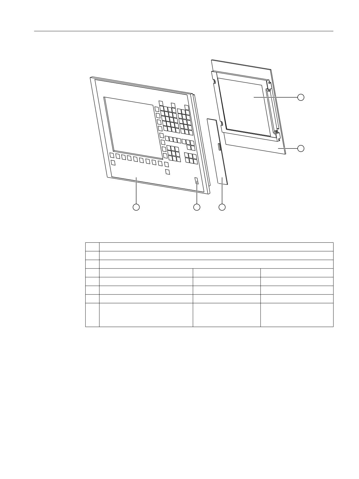
Operator panel front: OP 010
2.6 Spare parts
Image 2-5
Individual parts for the OP 010 operator panel front
①
Display with backlighting and backlight inverter
②
Display support
③
Keyboard controller
Spare parts
Order number
Remarks
④
Cap for the USB port
6FC5248-0AF05-0AA0
Set of 10
⑤
Operator panel front without display
6FC5248-0AF00-0AA0
Tension jacks
6FC5248-0AF06-0AA0
Set of 6
DIN A4 film
6FC5248-0AF07-0AA0
for slide-in labels for softkey
labeling*)
Set of 3
*) The dimensions for production of film slide-in labels for softkey labeling can be seen in the
following diagram.
Operator panels
Manual, 03/2016, 6FC5397-1AP40-5BA3
37
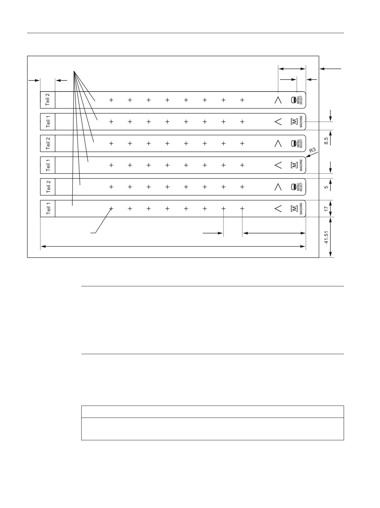
Operator panel front: OP 010
2.6 Spare parts
6OLGH LQ ODEHOV
&HQWHU RI WKH NH\
Image 2-6
Dimensions for DIN A4 film
Note
The symbols for the four softkeys for navigation in the menus shown in the figure are not
contained in the blank film. You can obtain the symbols from the "Symbols_OP08T_13.doc"
document that accompanies the DOConCD. Alternatively, you can also use the
"Template_OP010.pdf" file as print template also provided on the DOConCD - under Separate
supply > Slide-in labels > OP010. To print the film, proceed as described in the associated
manual "Operator panel front: OP08T" under "Accessories" in Section "Printing the slide-in
labels".
2.6.2
Replacement
NOTICE
Risk of damage to sensitive components due to static electricity
Spare parts must always be replaced by properly trained personnel!
Operator panels
38
Manual, 03/2016, 6FC5397-1AP40-5BA3
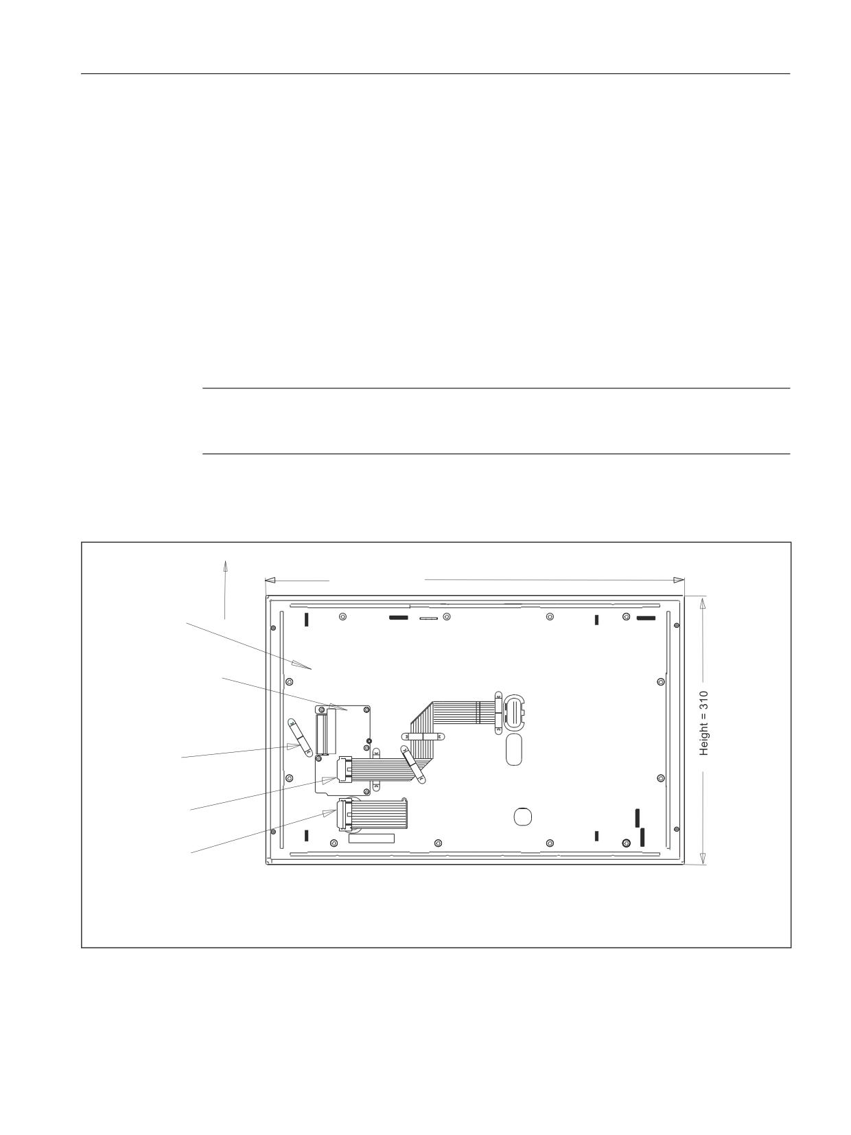
Operator panel front: OP 010
2.6 Spare parts
USB cap / tension jack
The replacement of the USB sealing cap and tension jacks will not be described since it is
simple and self-explanatory.
Film labels
The procedure for replacement is as described in Section: "OP 012", Section: "Softkey labels".
Operator panel front
When replacing the operator panel front, the previous display and keyboard controller can
continue to be used. They are therefore disassembled and reassembled after the appropriate
component has been replaced.
Note
We recommend reusing the keypad controller to prevent any loss of the control parameters
that have been programmed in.
Procedure
:LGWK
WRS
'LVSOD\
VXSSRUW SODWH
&RYHU SODWH IRU
&RQQHFWLRQV
.H\ERDUG FRQWUROOHU
&DEOH
FODPS
'LVSOD\
FDEOH .
,2 86%
FDEOH .
0RXQWLQJ VORWV IRU 3&8 OXJV
&DEOH VKRZQ IROGHG WRJHWKHU
&DVLQJ VFUHZV
6OLW IRU VRIWNH\ ODEHOLQJ VWULSV
Image 2-7
OP 010 rear side
Operator panels
Manual, 03/2016, 6FC5397-1AP40-5BA3
39
Operator panel front: OP 010
2.6 Spare parts
1. Put the OP 010 face down on a flat, soft surface and loosen the 12 housing screws (see
figure above).
2. Remove the softkey labeling strips and the cover plate.
3. Remove the following connectors from the keyboard controller (see following Figure):
Backlight (socket X14) and I/O USB cable K1.
4. Lift off the display support with the display.
In addition to the keyboard controller, the rear sides of the mouse and USB interface
become visible.
5. After bending back the two lugs, withdraw the USB interface.
6. Disconnect the three membrane connectors of the operator panel front keyboard from
sockets X7, X8 and X10 (see note below for procedure).
7. Remove the retaining screws from the keyboard controller.
Operator panels
40
Manual, 03/2016, 6FC5397-1AP40-5BA3