SINUMERIK 840D sl Hardware. Manual (2011-2020) - page 3
Operator panel front: OP 010
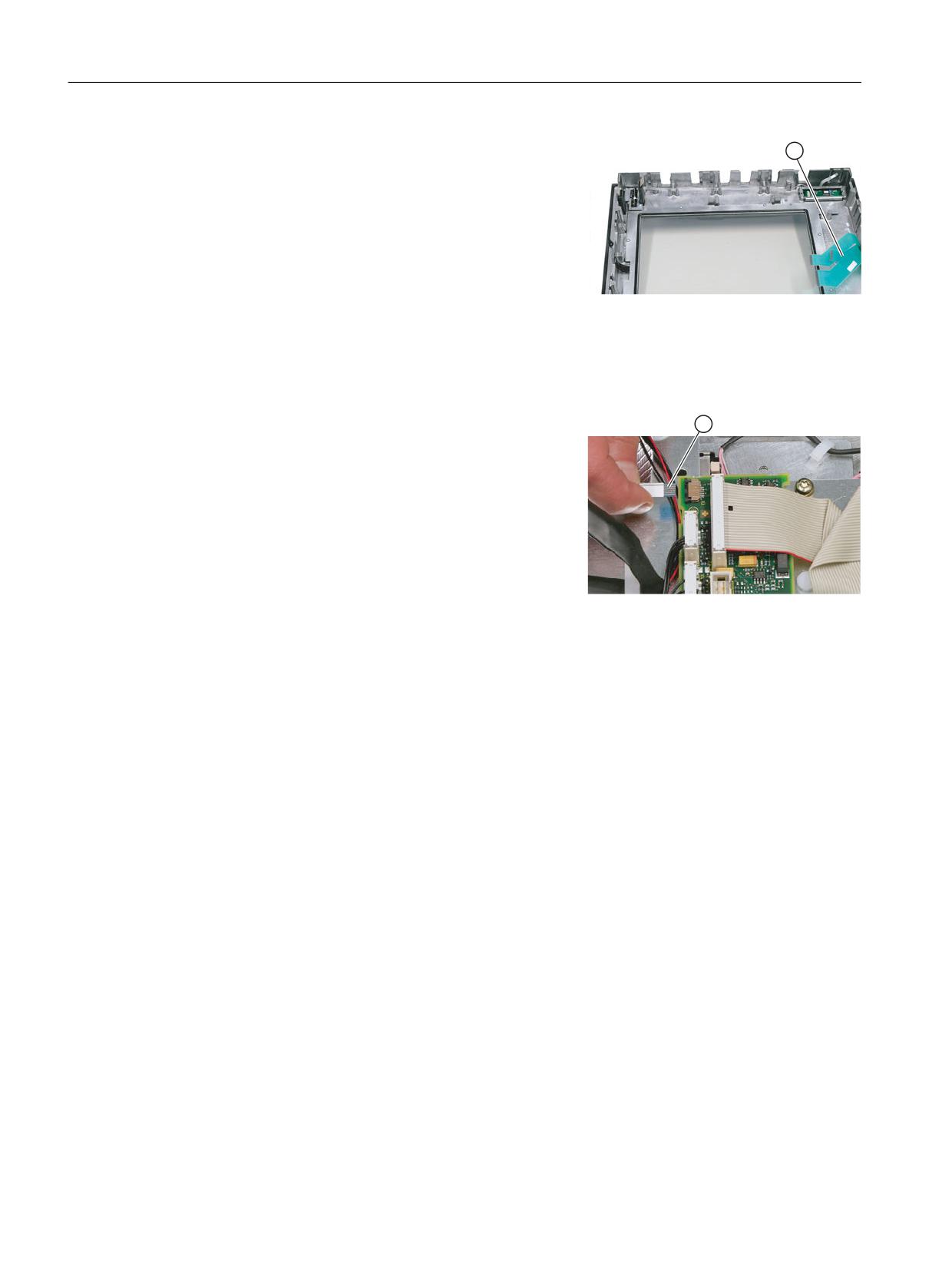
2.6 Spare parts
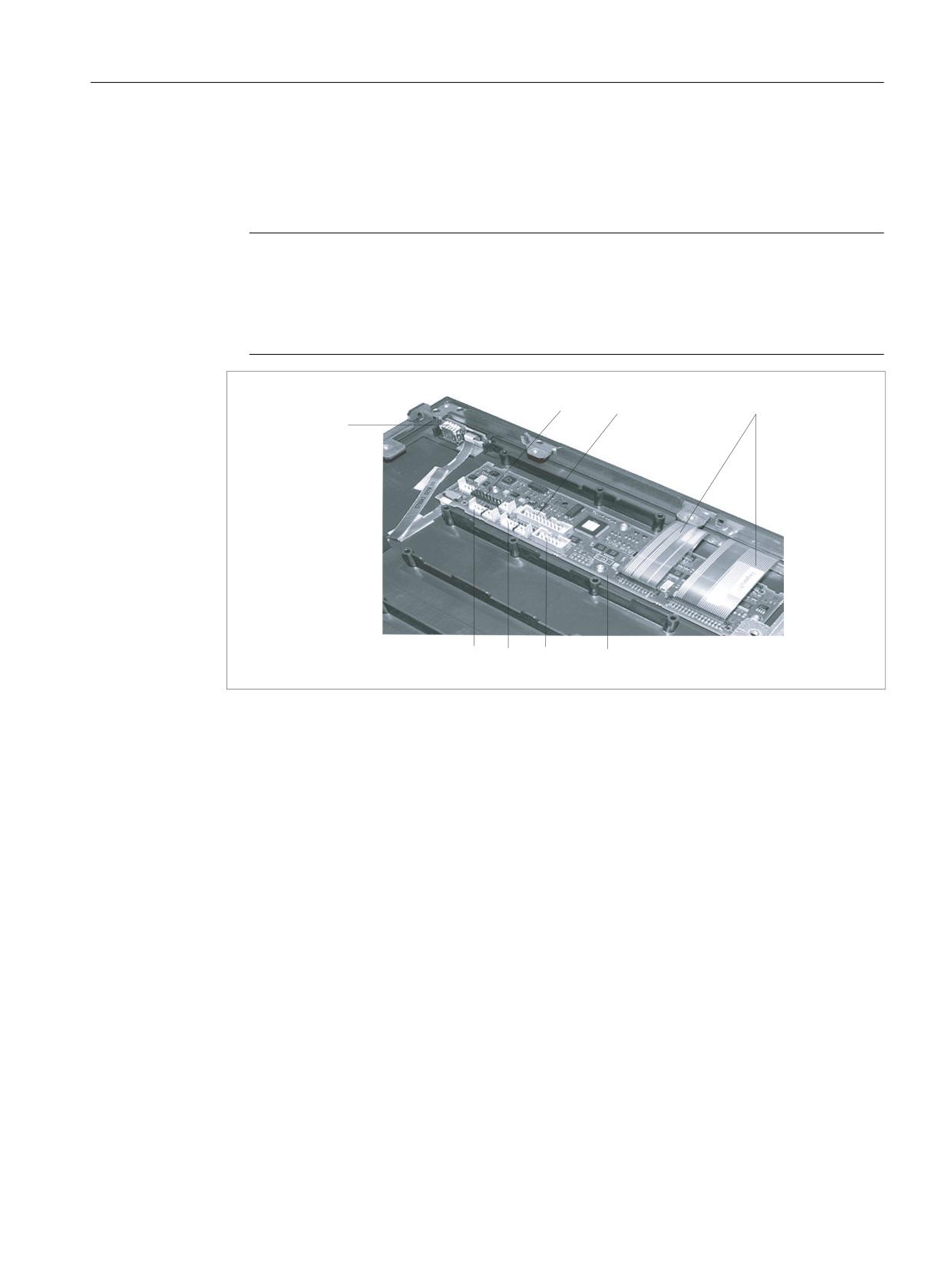
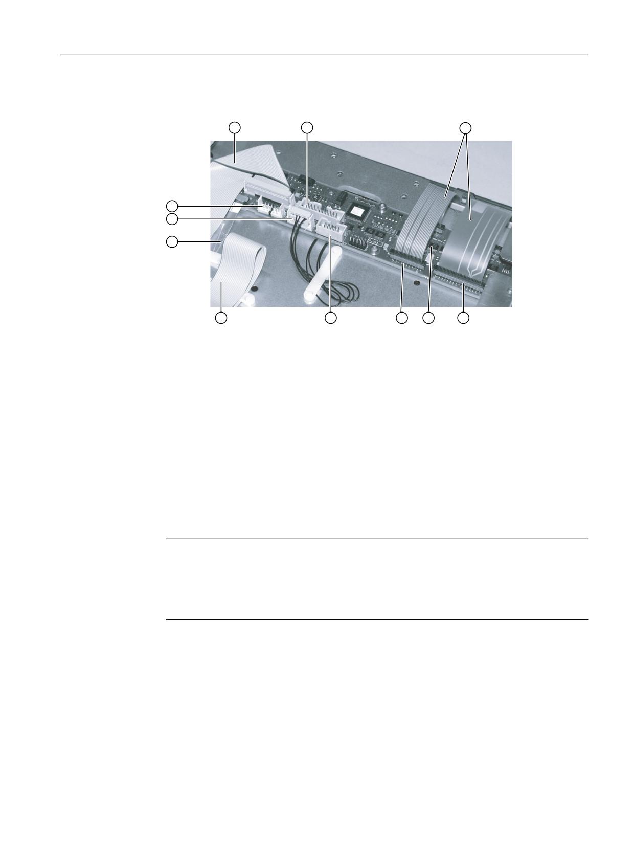
8. Lift USB interface and keyboard controller off the front plate. The interconnections may
remain plugged.
9. Install the components into the new operator front panel in reverse order (procedure: see
Note).
Note
Descriptions of how to disconnect and connect the membrane connector can be found in
"General information and networking", Chapter: "Connecting", Section: "Handling
membrane connectors".
When tightening the screws, observe the torques (refer to Section: "Technical data").
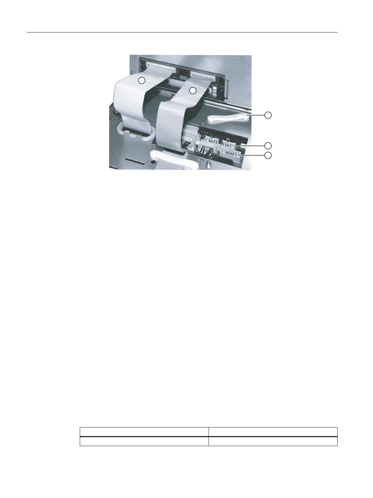
(1)
USB interface
(2)
Connection X1 for I/O USB cable K1
(3)
Direct key connection X11
(4)
Membrane connector for connecting the keyboard of the operator panel front
(5)
Keyboard controller
(6)
Connection X12 (reserved)
(7)
Connection X14 for backlight
(8)
Connection X4 for mouse
Image 2-8
Changing the operator panel front
Operator panels
Manual, 03/2016, 6FC5397-1AP40-5BA3
41
Operator panel front: OP 010S
3
3.1
Description
The slimline SINUMERIK OP 010S operator panel front and 10.4" TFT color display with a
resolution of 640 x 480 pixels (VGA) features 8 +4 horizontal softkeys and 8 vertical softkeys.
It is fixed from the rear using special clamps that are included in the delivery scope.
Validity
The description below applies to the OP 010S operator panel front
Article number 6FC5203-0AF04-0AA0
Features
The OP 010S operator panel front described in the following is characterized by:
● Mounting dimensions 310 x 330 mm
● Panel cutout (W x H): 285 x 304 mm
● Limited mounting depth
●
10.4" TFT flat screen (color) with VGA resolution 640 x 480 pixels
● Mechanical keys:
-
8 horizontal softkeys
–
8 vertical softkeys
–
4 control keys
● Status LEDs for power supply and overtemperature
● Front USB interface
● Degree of protection: IP54
● Attachment: Tension jacks at the rear
● Can be combined with PCU, TCU and a CNC full keyboard
Operator panels
Manual, 03/2016, 6FC5397-1AP40-5BA3
43
Operator panel front: OP 010S
3.2 Operating and display elements
3.2
Operating and display elements
3.2.1
View
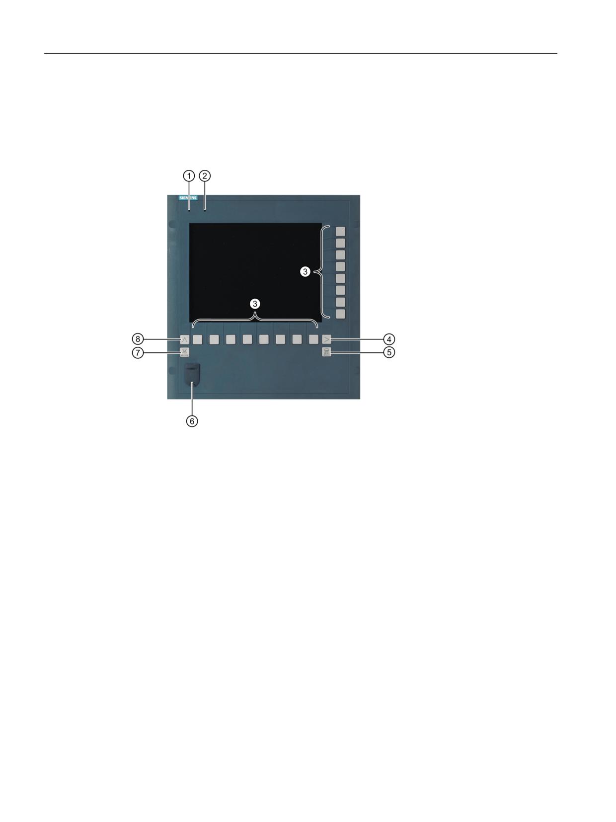
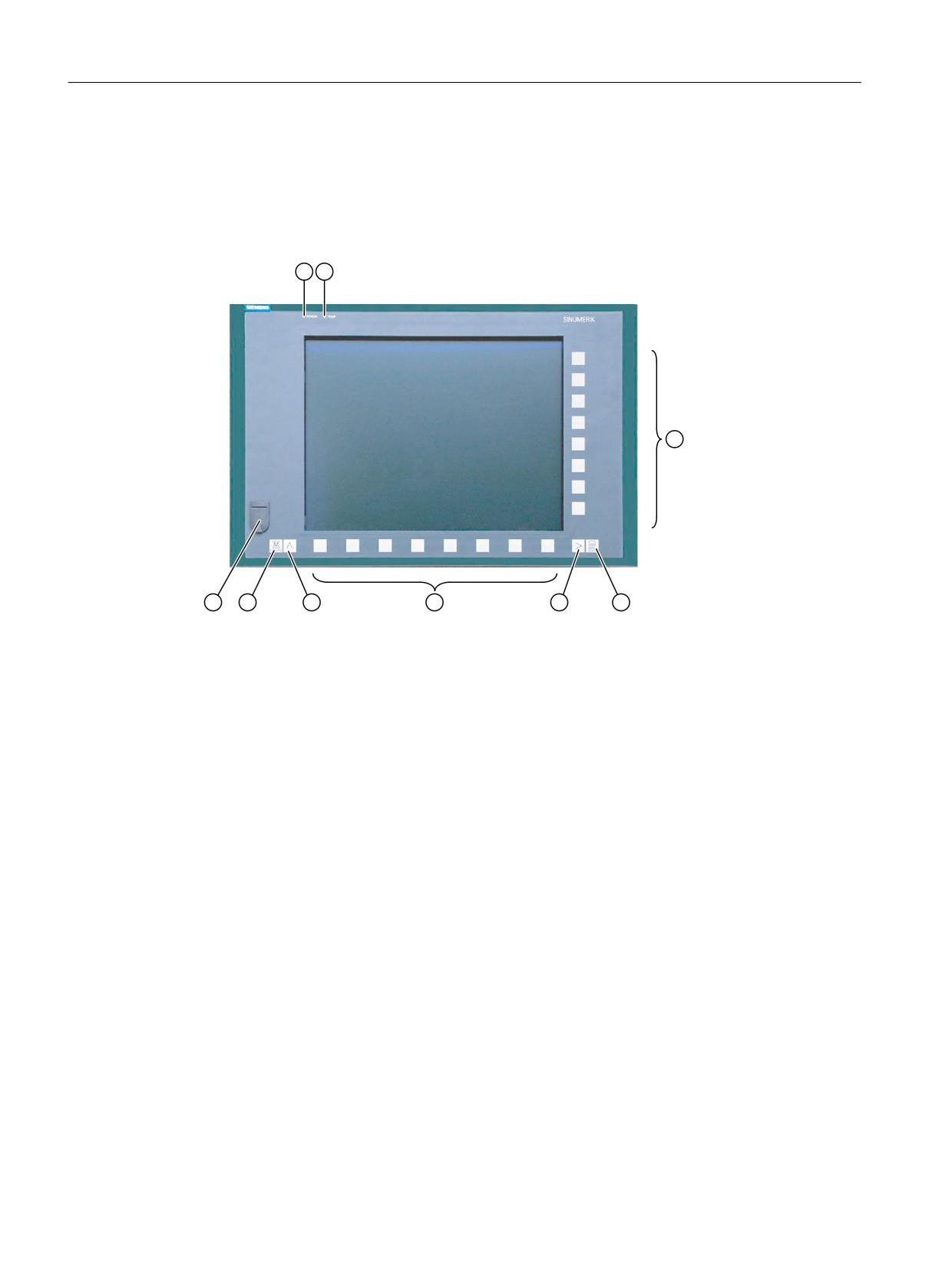
① Status LED: POWER
② Status LED: TEMP
Lit LEDs indicate increased wear.
③ Softkeys
④ Menu forward key
⑤ Menu select key
⑥ Front USB interface
⑦ Machine area button
⑧ Menu back key
Image 3-1
View of the OP 010S operator panel front
3.2.2
Keyboard
Keyboard
Several keys are arranged on the operator panel front:
● The eight vertical and horizontal softkeys call up functions that are available on screen via
a menu bar.
● The "Menu back" key switches back to the higher-level horizontal menu.
Operator panels
44
Manual, 03/2016, 6FC5397-1AP40-5BA3
Operator panel front: OP 010S
3.3 Interfaces
● The "Menu forward" key advances in the extended horizontal softkey bar.
● The "Menu select" key calls the main menu to select the operating area.
● The "Machine area" key selects the "Machine" operating area.
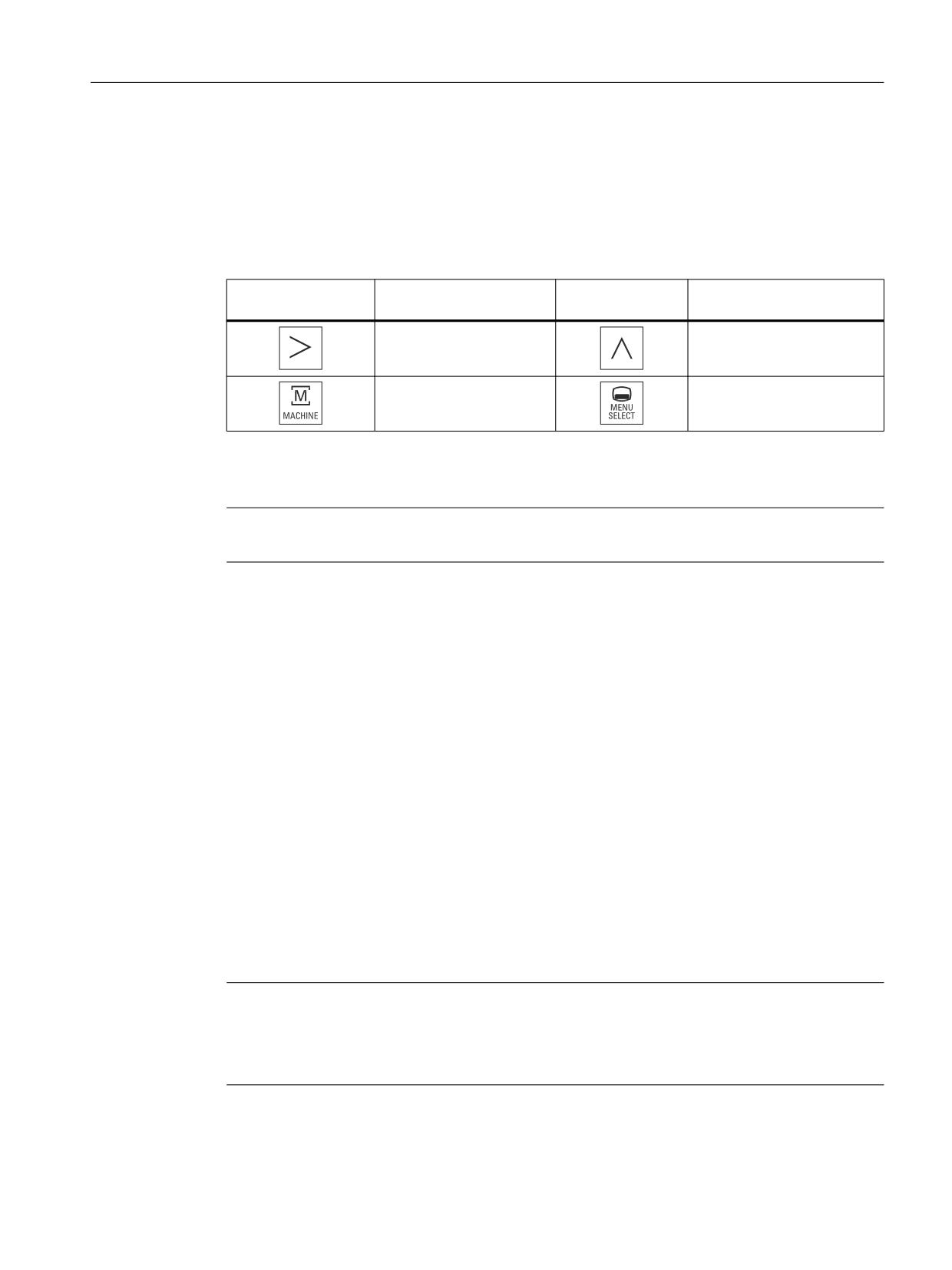
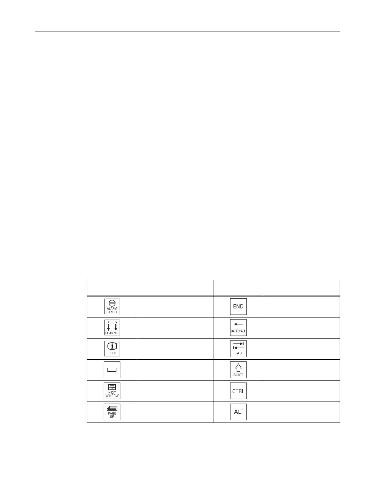
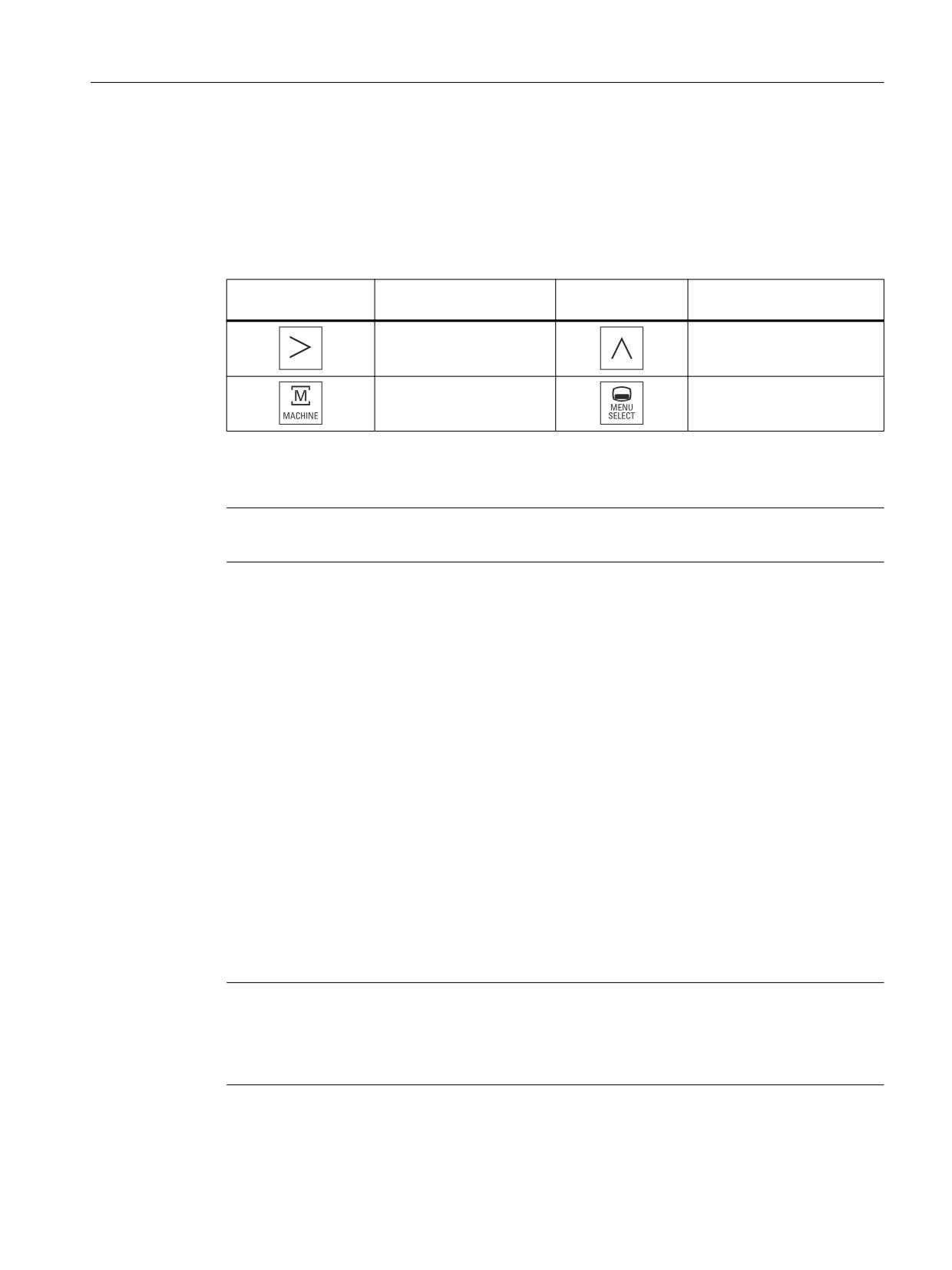
The key symbols used on the operator panel front are shown below along with the
corresponding function keys on the PC keyboard.
Key
Function corresponds to
Key
Function corresponds to the
the PC key function
PC key function
<Shift> F9
F9
<Shift> F10
F10
Display
Note
Pixel error according to DIN EN ISO 13406-2 Class II.
3.2.3
Screen saver
If a screen with high contrast is displayed unchanged for longer than an hour, then the
screensaver must be activated in order to protect the TFT display against so-called "burning
in" of the last displayed screen.
The time can be adapted individually. Further information can be found at:
Commissioning of Basic Software and Operating Software, SINUMERIK Operate (IM9)
3.3
Interfaces
Front
USB 1.1 Full Speed (socket, type A) for connecting an external keyboard, mouse and USB
flash drive (see Image 3-1 View of the OP 010S operator panel front (Page 44)).
Note
Note that the electromagnetic compatibility of commercially available peripheral devices
operated via the USB interface is usually rated for office use only.
For industrial use, components with a higher degree of certification are recommended.
Operator panels
Manual, 03/2016, 6FC5397-1AP40-5BA3
45
Operator panel front: OP 010S
3.4 Mounting
Rear
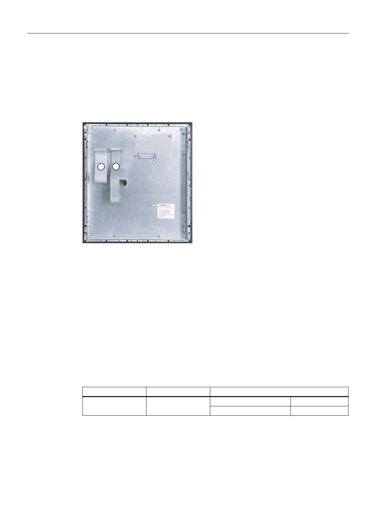
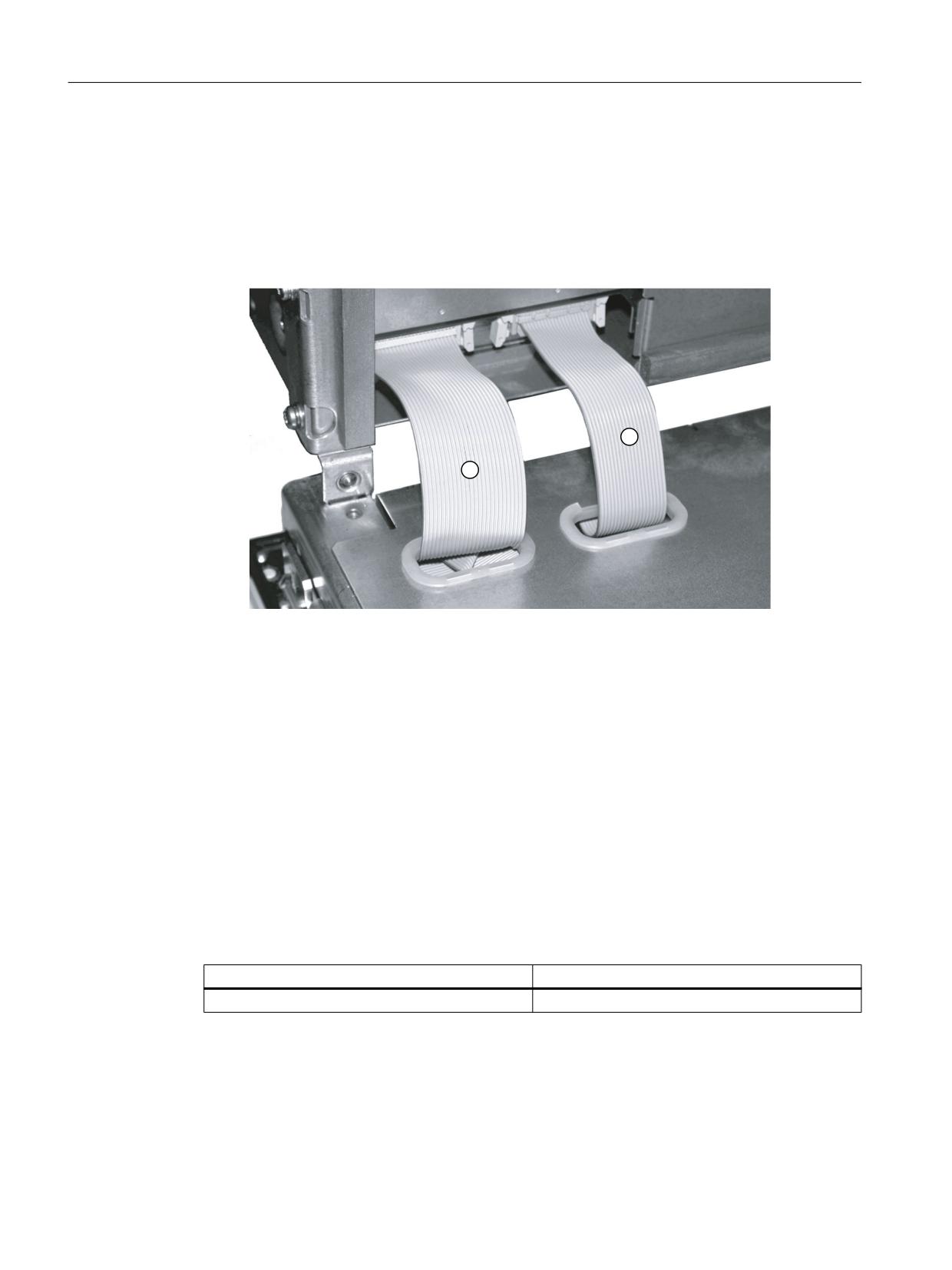
Two flat ribbon cables for connecting the PCU/TCU:
● I/O USB cable K1 ①:
All signals that are used for the display interface and the connection of operator panel fronts
(e.g. supply voltages)
● Display cable K2 ②
Image 3-2
Connections on rear of housing
Pin assignment
For more detailed information, see "General information and networking", Chapter:
"Connecting".
3.4
Mounting
3.4.1
Preparation for mounting
Table 3-1
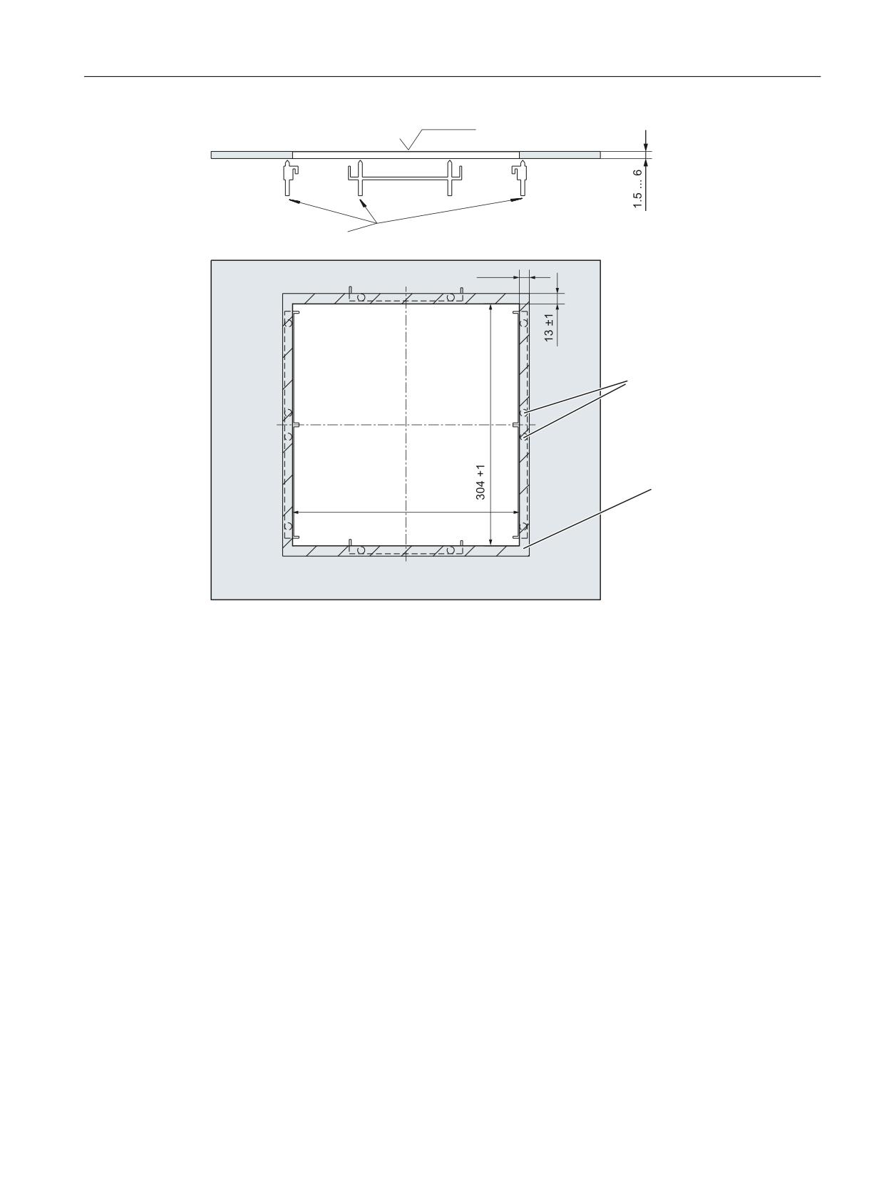
Dimensions of the mounting opening
Width (mm)
Height (mm)
Mounting depth T3 + clearance (mm)
285
304
with PCU 50.5
120 + 10
With TCU x0.2
69 + 10
Thanks to the tension jacks on the OP 010S, drill-holes or screw holes are not needed.
This retaining method also enables the IP65 degree of protection (but only in conjunction with
a circumferential seal and when the protective USB cap is fitted).
Operator panels
46
Manual, 03/2016, 6FC5397-1AP40-5BA3
Operator panel front: OP 010S
3.4 Mounting
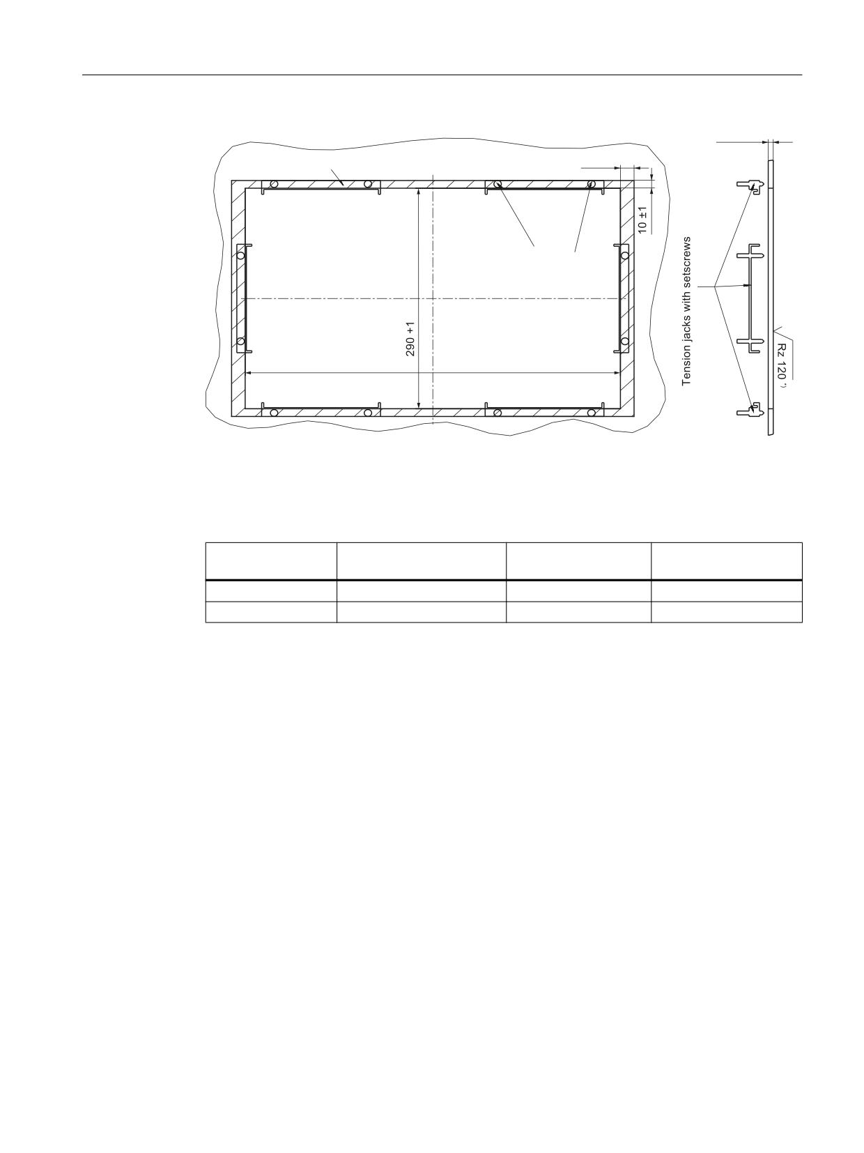
,Q WKH VHDOLQJ DUHD
5]
7HQVLRQ MDFNV ZLWK VHWVFUHZV
s
3UHVVXUH SRLQWV
IRU WHQVLRQ MDFNV
6HDOLQJ DUHD
Image 3-3
Dimension sheet for installing the OP 010S operator panel front
Operator panels
Manual, 03/2016, 6FC5397-1AP40-5BA3
47
Operator panel front: OP 010S
3.4 Mounting
7
s
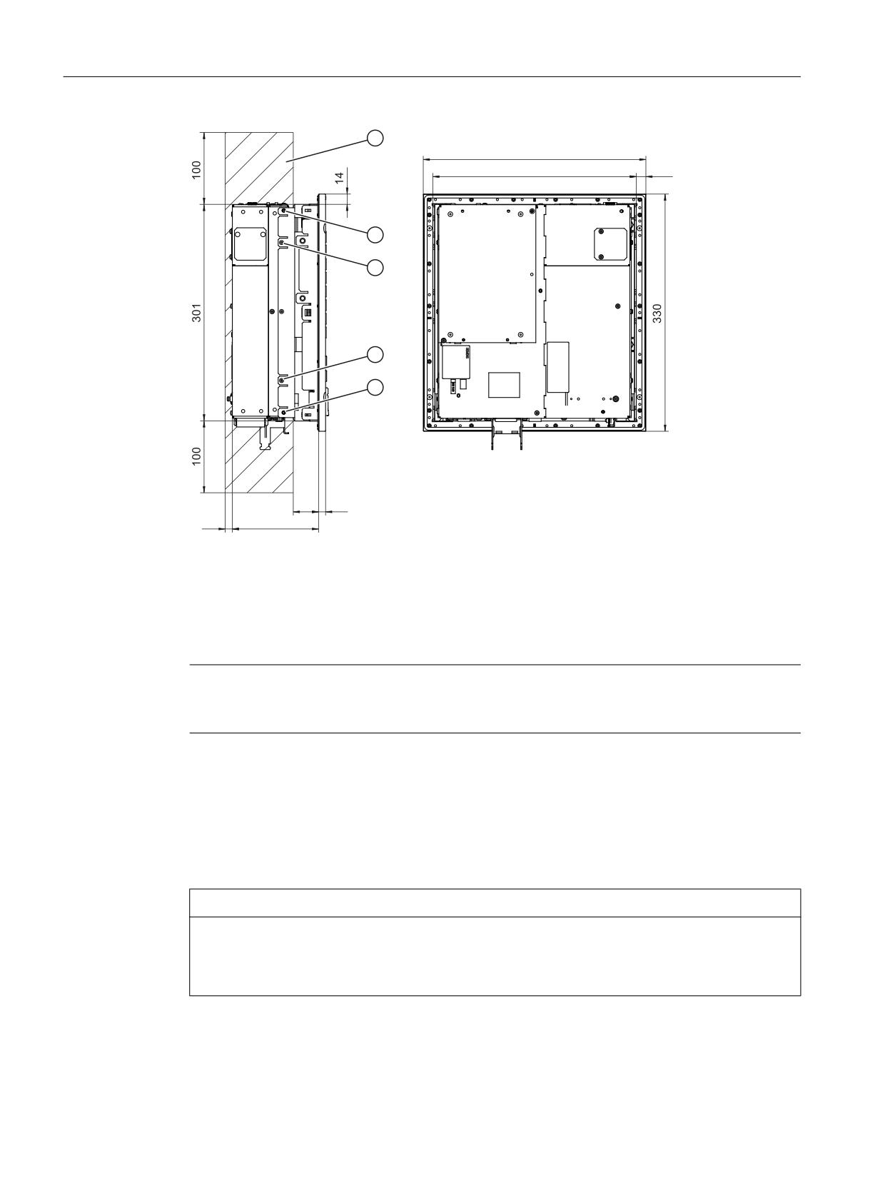
① Clearance for cables and ventilation
② M4x8 housing screws for attaching the PCU
③ M3x8 housing screws for attaching the PCU/TCU
Image 3-4
Attaching the PCU to the OP010S operator panel front
Note
The 100 mm clearance above and below the PCU is not necessary when assembled with a
TCU as a TCU does not have any fan in its housing.
3.4.2
Mounting on the mounting wall
When you are using a combination of OP 010S and PCU, it is advisable to install the OP 010S
in the assembly panel first and then mount the PCU on the OP 010S.
NOTICE
Impermissible mounting positions can cause malfunctions
Observe the permissible mounting position: Deviating by up to 5º from the vertical.
This value can be further restricted by mounted components (e.g. PCU).
Operator panels
48
Manual, 03/2016, 6FC5397-1AP40-5BA3
Operator panel front: OP 010S
3.5 Technical data
Procedure
1. Insert the OP 010S in the panel cutout from the front.
2. Use six tension jacks to secure it in the panel cutout from the rear (see Image 3-3 Dimension
sheet for installing the OP 010S operator panel front (Page 47)).
3. Tighten the setscrews (tightening torque 0.4 - 0.5 Nm).
3.4.3
Assembling an OP 010S and a PCU
Procedure
1. Position the PCU approximately at right angles to the OP.
2. Insert cable connectors K1 and K2 of the OP into the corresponding counterpieces behind
the opening in the PCU housing.
Ensure that the connectors snap in and that the locks are closed.
3. Fold the PCU onto the OP.
4. Using the four M3 and four M4 screws supplied, attach the PCU to the side of the OP
(tightening torques: M3 0.8 Nm; M4 1.8 Nm).
The clearance at the rear of the PCU must be at least 10 mm to ensure sufficient ventilation
(see Image 3-4 Attaching the PCU to the OP010S operator panel front (Page 48)).
For more detailed information, please refer to the relevant PCU sections and in "General
information and networking", Section: "Application planning", Section: "Climatic and
mechanical environmental conditions" → "Cooling".
Note
The OP 010S and TCU assembly is similar to that for a PCU.
3.5
Technical data
Safety
Safety class
III; PELV according to EN 50178
Degree of protection accord-
Front side IP54
ing to EN 60529
Rear side IP00
Approvals
CE / cULus
Electrical data (without PCU)
Power supply
Display
Backlight inverter
Logic / USB
(via K1 and K2)
(with / without load)
Voltage
5 V +/- 5%
12 V +/- 10%
5.2 V +/-2%
Current (typ./max.)
approx. 420/600 mA
approx. 900/1050 mA
approx. 350/1000 mA
Operator panels
Manual, 03/2016, 6FC5397-1AP40-5BA3
49

Operator panel front: OP 010S
3.6 Spare parts
Power consumption
Typical, approx. 10 W
Maximum approx. 16 W
Mechanical data
Dimensions
Width: 310 mm
Height: 330 mm
Depth: 45 mm
Weight
approx. 5.5 kg
Tightening torques, max.
Tension jack screws:
M3 screws:
M4 screws:
0.5 Nm
0.8 Nm
1.8 Nm
Display
Size / resolution
10.4" TFT / 640 x 480 pixels
MTBF backlight
typ. 50,000 h at 25º C (dependent on the temperature)
Note
Information about the climatic and mechanical environmental conditions is contained in the
associated section under:
"General notes and interconnection" → "Operational planning".
3.6
Spare parts
3.6.1
Overview
Spare part
Article number
Remark
Caps for the USB port
6FC5248-0AF05-0AA0
Set of 10
Tension jacks
6FC5248-0AF06-0AA0
Set of 6
3.6.2
Replacement
NOTICE
Risk of damage to sensitive components due to static electricity
Spare parts must always be replaced by properly trained personnel!
USB cap / tension jack
The replacement of the USB sealing cap and tension jacks will not be described since it is
simple and self-explanatory.
Operator panels
50
Manual, 03/2016, 6FC5397-1AP40-5BA3
Operator panel front: OP 010C
4
4.1
Description
The SINUMERIK OP 010C operator panel front and 10.4" TFT color display with a resolution
of 640 x 480 pixels (VGA) features a 65-key mechanical keyboard with 8 + 4 horizontal softkeys
and 8 vertical softkeys.
The 6 hotkeys are designed with replaceable key covers for machine-specific adaptation. The
key covers can be freely inscribed using a laser.
The operator panel front is secured from the rear using special clamps supplied with the panel.
Validity
The description below applies to the OP 010C operator panel front
Article number 6FC5203-0AF01-0AA0
Features
●
19" mounting format, 7 HU (height units)
● Panel cutout (W x H): 450 x 290 mm
● Limited mounting depth
●
10.4" TFT flat screen (color) with VGA resolution 640 x 480 pixels
● Mechanical short-stroke keys with alphabetic, numeric, cursor, control and hotkey key pad
● Softkeys:
-
1 horizontal row of 8 keys with softkey functions
-
1 vertical row of 8 keys with softkey functions
● Shift key for switchover to the second key level (not for switching over the letters, since
they are uppercase only)
● Status LEDs for power supply and overtemperature
● Front USB interface
● Degree of protection IP 54
● Attachment: Tension jacks at the rear
● Can be combined with PCU, TCU
Operator panels
Manual, 03/2016, 6FC5397-1AP40-5BA3
51
Operator panel front: OP 010C
4.2 Operating and display elements
4.2
Operating and display elements
4.2.1
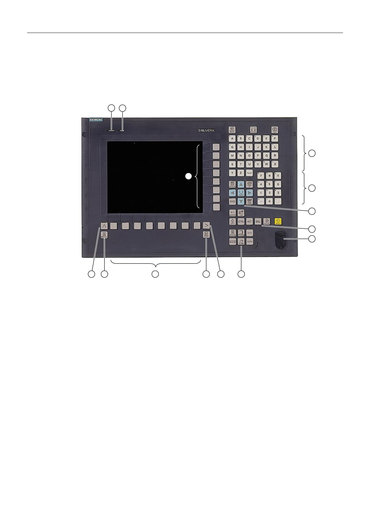
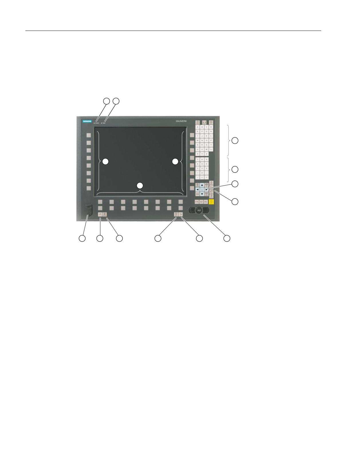
View
① Status LED: POWER
② Status LED: TEMP
Lit LEDs indicate increased wear.
③ Vertical softkeys
④ Alphabetic key group
⑤ Numeric key group
⑥ Cursor key group
⑦ Control key group
⑧ Front USB interface
⑨ Hotkey group
⑩ Menu forward key
⑪ Menu select key
⑫ Horizontal softkeys
⑬ Machine area button
⑭ Menu back key
Image 4-1
View of operator panel front OP 010C
Operator panels
52
Manual, 03/2016, 6FC5397-1AP40-5BA3
Operator panel front: OP 010C
4.2 Operating and display elements
4.2.2
Keyboard
Keyboard
Several keys and keypads are installed on the OP 010C operator panel front:
● The alphabetic block contains the letters A - Z and the space character.
● The numeric block contains the digits 0 - 9, and the characters "-" and ".".
● The cursor key group is used to navigate on the screen.
● The control key group includes special functions.
● The hotkey group is used for the direct selection of operating areas.
● The softkeys call up functions that are available on the screen via a menu bar.
● The "Menu back" key switches back to the higher-level horizontal menu.
● The "Menu forward" key advances in the extended horizontal softkey bar.
● The "Menu select" key calls the main menu to select the operating area.
● The "Machine area" key selects the "Machine" operating area.
Switching between upper and lower case
To toggle between upper and lower case letters, press the key combination Ctrl + Shift
Upper case is always activated as standard.
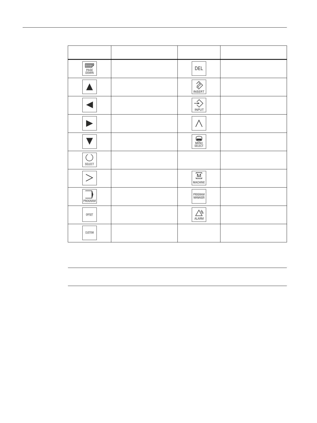
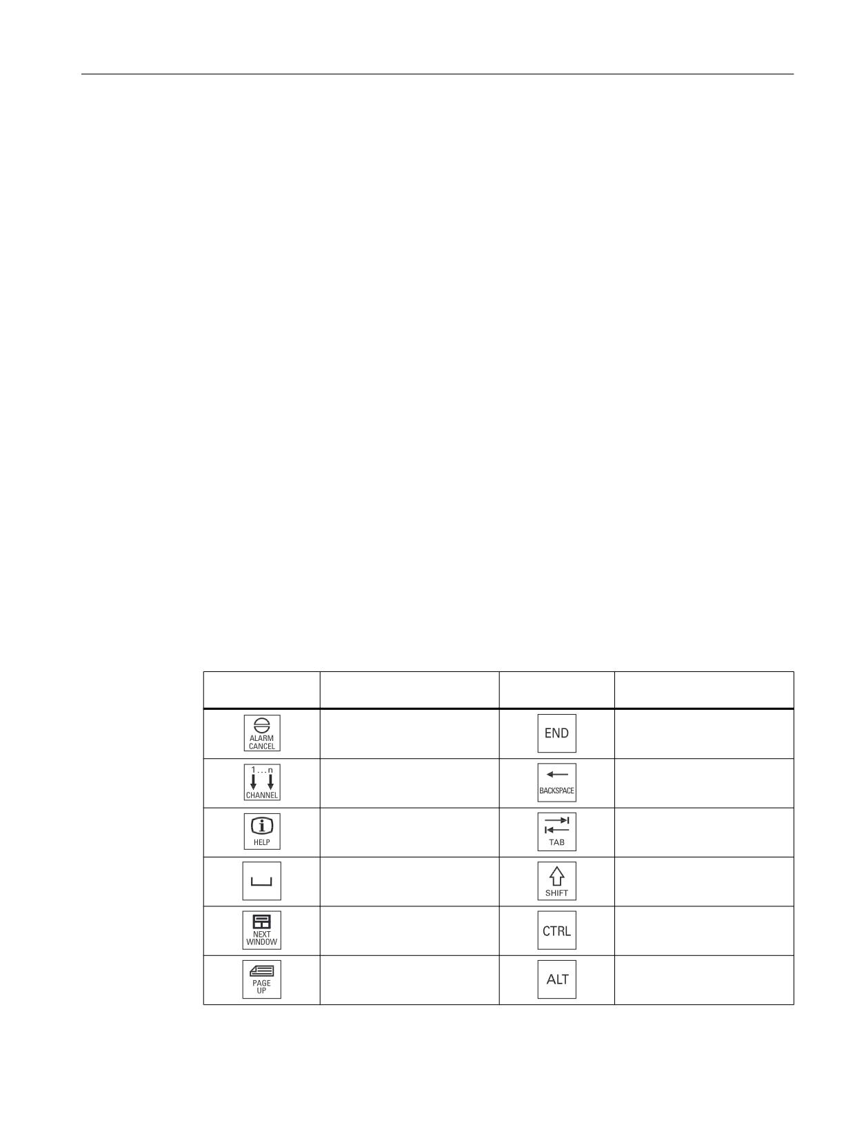
Overview of the key symbols
The key symbols used on the operator panel front are shown below along with the
corresponding function keys on the PC keyboard.
Key
Function corresponds to the
Key
Function corresponds to the
PC key function
PC key function
Esc
End
F11
Backspace
F12
Tab
Space
(only intended for internal key-
board changeover)
Home
Ctrl key
Page up
Alt key
Operator panels
Manual, 03/2016, 6FC5397-1AP40-5BA3
53
Operator panel front: OP 010C
4.2 Operating and display elements
Key
Function corresponds to the
Key
Function corresponds to the
PC key function
PC key function
Page down
Delete
Cursor up
Insert
Cursor left
Enter
Cursor right
F9
Cursor down
F10
5 (in numeric key group)
A, ..., Z
<Shift> A, ..., Z
<Shift> F9
<Shift> F10
Display
Note
Pixel error according to DIN EN ISO 13406-2 Class II.
4.2.3
Screen saver
If a screen with high contrast is displayed unchanged for longer than an hour, then the
screensaver must be activated in order to protect the TFT display against so-called "burning
in" of the last displayed screen.
The time can be adapted individually. Further information can be found at:
Commissioning of Basic Software and Operating Software, SINUMERIK Operate (IM9)
Operator panels
54
Manual, 03/2016, 6FC5397-1AP40-5BA3
Operator panel front: OP 010C
4.3 Interfaces
4.3
Interfaces
This operator panel front has the following interfaces:
Front
USB 1.1 Full Speed (type A) for connecting an external keyboard, mouse and USB flash drive
(see Fig. "View of operator panel front" in Section: "Control and display elements" → "View").
Note
Note that the electromagnetic compatibility of commercially available peripheral devices
operated via the USB interface is usually rated for office use only.
For industrial use, components with a higher degree of certification are recommended.
Operator panels
Manual, 03/2016, 6FC5397-1AP40-5BA3
55
Operator panel front: OP 010C
4.3 Interfaces
Rear
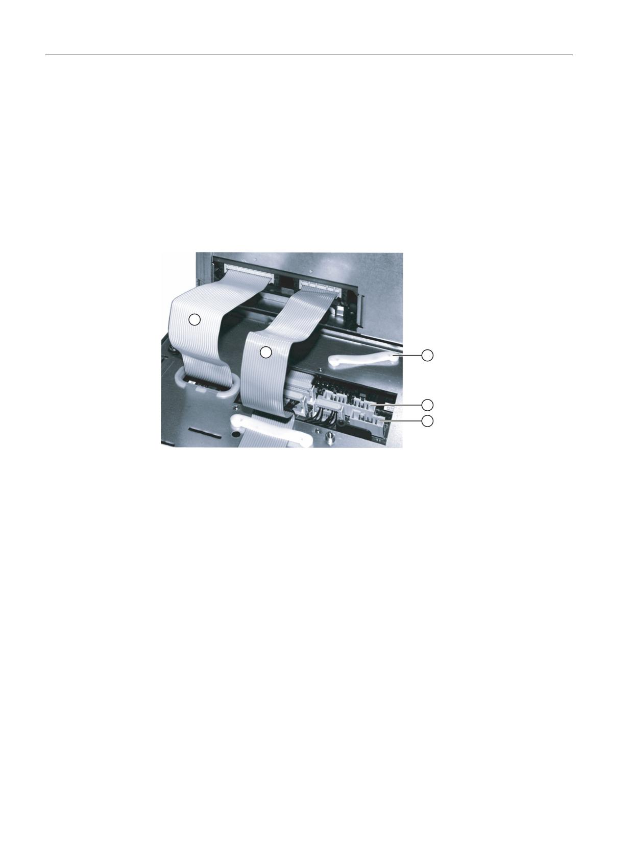
● Two flat ribbon cables for connecting the PCU:
- I/O USB cable K1
all signals that are used for the display interface and the connection of operator panel
fronts
(e.g. supply voltages)
- Display cable K2
● Direct key interface X11 (under the cover plate)
● Interface X12 - reserved (under the cover plate)
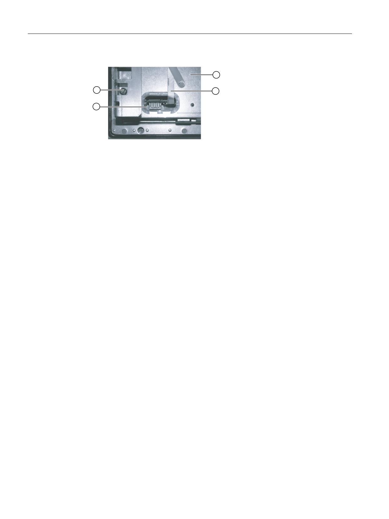
3&8
23
&
① I/O USB cable K1
② Display cable K2
③ Retainer for direct control key module connection
④ Direct key interface X11
⑤ Interface X12 (reserved)
Image 4-2
Connections on rear of housing Connections to PCU
Pin assignment
For more detailed information, see "General information and networking", Chapter:
"Connecting".
Operator panels
56
Manual, 03/2016, 6FC5397-1AP40-5BA3
Operator panel front: OP 010C
4.4 Mounting
4.4
Mounting
4.4.1
Preparation for mounting
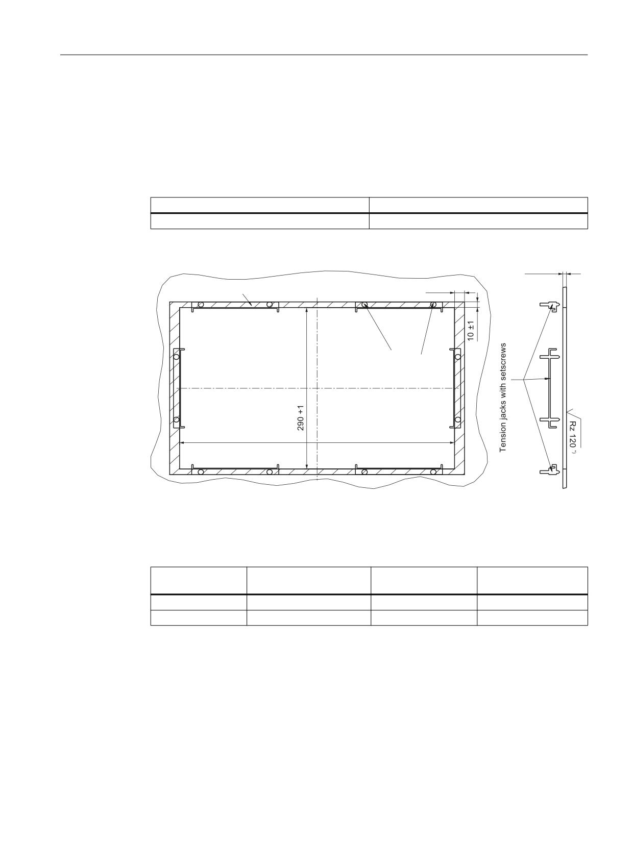
Table 4-1
Dimensions of the mounting opening
Width (mm)
Height (mm)
450
290
Thanks to the tension jacks on the OP 010C, drill-holes or screw holes are not needed.
6HDOLQJ DUHD
s
3UHVVXUH SRLQWV
IRU WHQVLRQ MDFNV
,Q WKH VHDOLQJ DUHD
Image 4-3
Dimension drawing for mounting the OP010C operator panel front
Table 4-2
Dimensions to be observed when installing
Mounting depth T3 + clear-
Opening depth T5
Protrusion P
ance (mm)
(mm)
(mm)
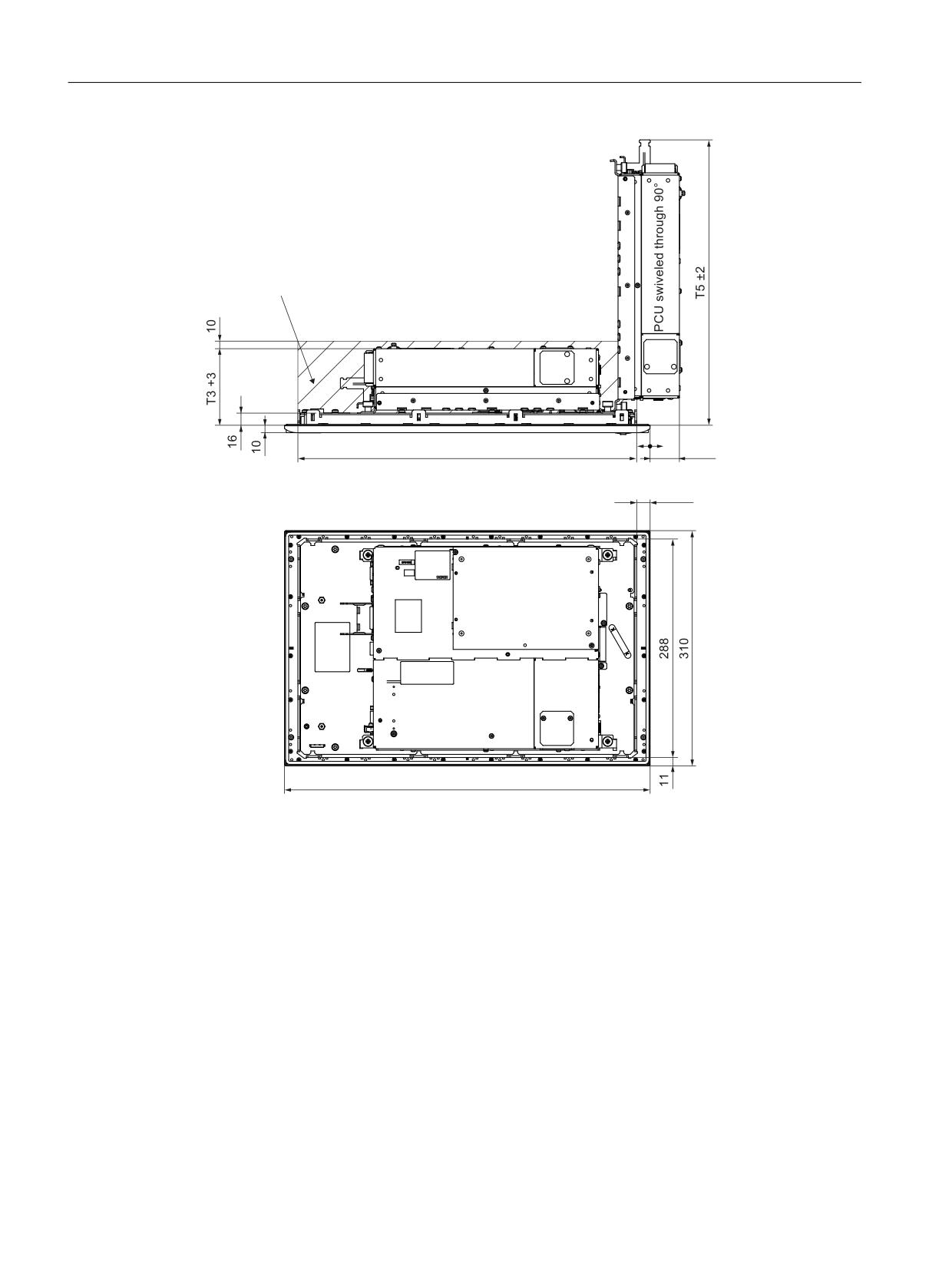
PCU 50.5
101 + 10
377
39
TCU x0.2
50 + 10
350
-12
Operator panels
Manual, 03/2016, 6FC5397-1AP40-5BA3
57
Operator panel front: OP 010C
4.4 Mounting
6SDFH IRU FDEOHV DQG YHQWLODWLRQ
3&8 LQ ILQDO SRVLWLRQ
s
s
s
Image 4-4
Dimension sheet for mounting the OP 010C with PCU
4.4.2
Assembling an OP 010C and a PCU
When combining an OP 010C and PCU, it is advisable to assemble them prior to installing
them in the assembly panel.
Procedure
To do this, proceed as described in the section: “OP 012”, section: "Assembling the OP 012
and PCU."
Operator panels
58
Manual, 03/2016, 6FC5397-1AP40-5BA3
Operator panel front: OP 010C
4.5 Technical data
4.4.3
Mounting on the mounting wall
The clearance at the rear of the PCU must be at least 10 mm to ensure sufficient ventilation
(see Figure: "Attaching the PCU to the OP 012 operator panel front", Section: "OP 012",
Section: "Assembling the OP 012 and PCU").
For more detailed information, please refer to the relevant PCU sections and in "General
information and networking", Section: "Application planning", Section: "Climatic and
mechanical environmental conditions" → "Cooling".
NOTICE
Impermissible mounting positions can cause malfunctions
Observe the permissible mounting position: Deviating by up to 5º from the vertical.
This value can be further restricted by mounted components (e.g. PCU).
Procedure
1. Insert the assembled components (operator panel front and PCU) from the front into the
panel cutout (see Image 4-3 Dimension drawing for mounting the OP010C operator panel
front (Page 57)).
2. Secure the operator panel front in the panel cutout from the rear using the tension jacks by
tightening the setscrews (torque 0.4 - 0.5 Nm).
4.5
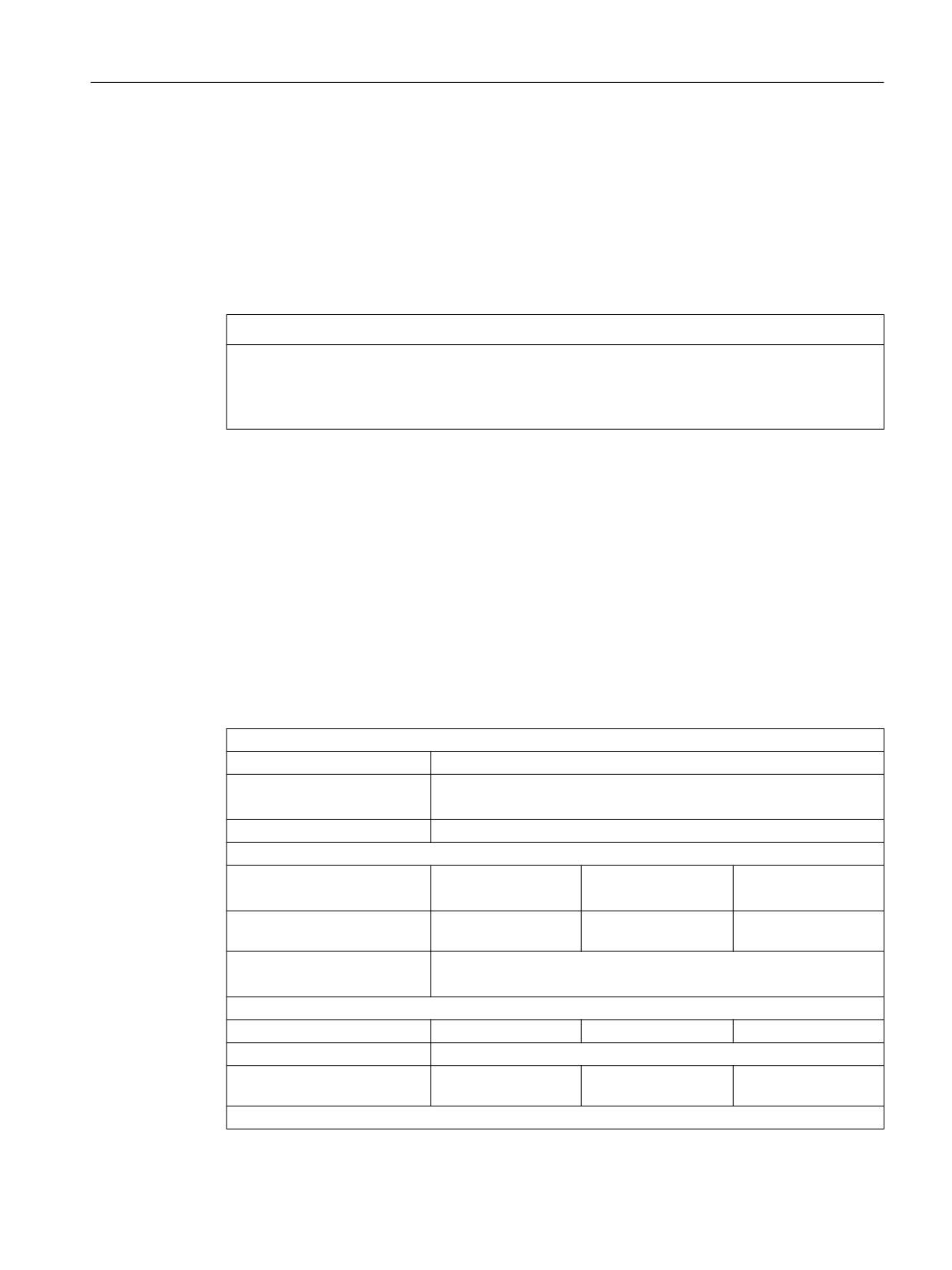
Technical data
Safety
Safety class
III; PELV according to EN 50178
Degree of protection accord-
Front side IP54
ing to EN 60529
Rear side IP00
Approvals
CE / cULus
Electrical data
Power supply
Display
Backlight inverter
Logic / USB
(via K1 and K2)
(with / without load)
Voltage
5 V +/- 5%
12 V +/- 10%
5.2 V +/- 2%
Current (typ./max.)
approx. 280/380 mA
approx. 750/1000 mA
approx. 350/1000 mA
Power consumption
Typical, approx. 10 W
Maximum approx. 16 W
Mechanical data
Dimensions
Width: 483 mm
Height: 310 mm
Depth: 30 mm
Weight
Approx. 5 kg
Tightening torques, max.
Tension jack screws:
M3 screws:
M4 screws:
0.5 Nm
0.8 Nm
1.8 Nm
Display
Operator panels
Manual, 03/2016, 6FC5397-1AP40-5BA3
59
Operator panel front: OP 010C
4.6 Spare parts
Size / resolution
10.4" TFT / 640 x 480 pixels
MTBF backlight
typ. 50,000 h at 25º C (dependent on the temperature)
Note
Information about the climatic and mechanical environmental conditions is contained in the
associated section under:
"General notes and interconnection" → "Operational planning".
4.6
Spare parts
4.6.1
Overview
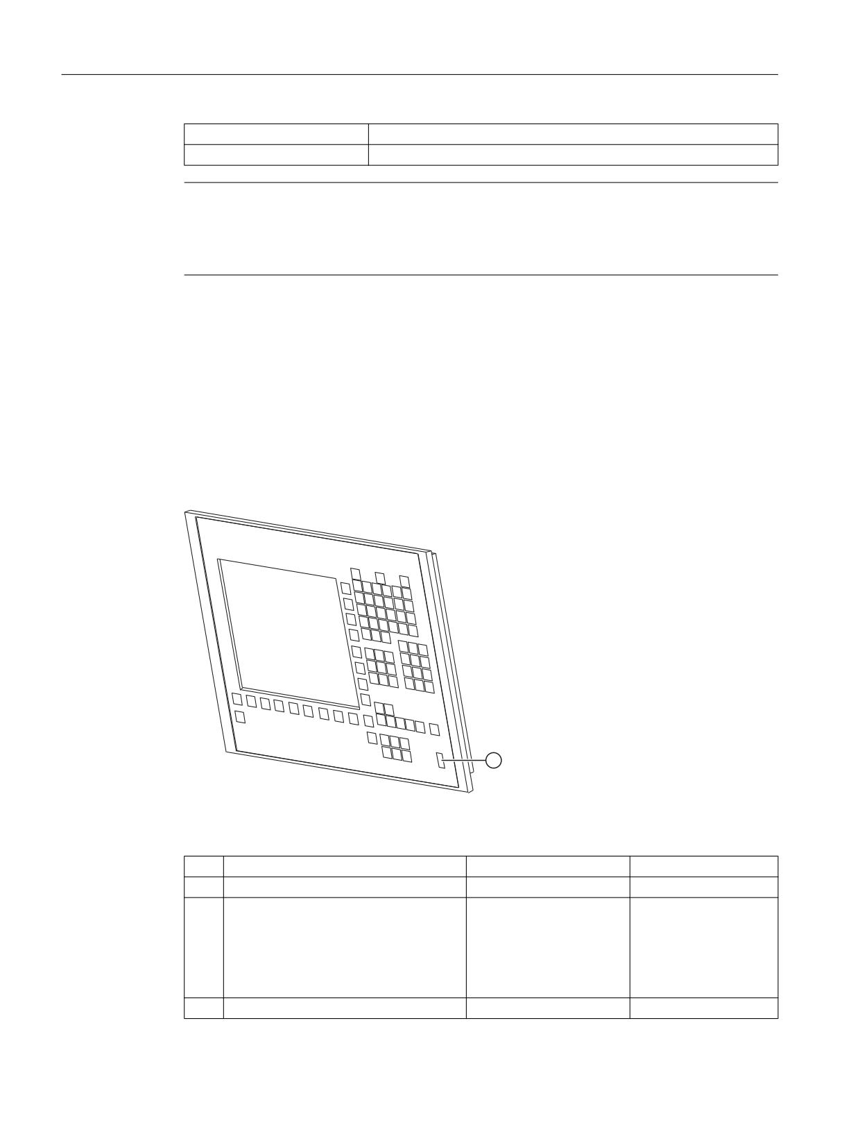
The diagram shows the OP 010C front plate as an individual part.
The components available as spare parts are combined in an overview.
Image 4-5
Front plate of OP 010C
Spare part
Article number
Remark
(1)
Caps for the USB port
6FC5248-0AF05-0AA0
Set of 10
Key cover (for labeling)
6FC5248-0AF12-0AA0
Set with
90 ergo-gray items
20 red items
20 yellow items
20 green items
20 medium gray items
Tension jacks
6FC5248-0AF06-0AA0
Set of 6
Operator panels
60
Manual, 03/2016, 6FC5397-1AP40-5BA3
Operator panel front: OP 012
5
5.1
Description
The SINUMERIK OP 012 operator panel front and 12.1" TFT color display with a resolution of
800 x 600 pixels (SVGA) features a 59-key membrane keypad as well as 2 x (8 + 2) horizontal
and 2 x 8 vertical softkeys. The 2 x 8 vertical softkeys can be used as direct keys.
It is fixed from the rear using special clamps that are included in the delivery scope.
Validity
The description below applies to the OP 012 operator panel front.
Order number 6FC5203-0AF02-0AA1
Features
●
19" mounting format, 7 HU (height units)
● Panel cutout (W x H): 450 x 290 mm
● Limited mounting depth
●
12.1" TFT flat screen (color) with SVGA resolution 800 x 600 pixels
● Membrane keyboard with alphabetic, numeric, cursor, and control keypad
● Soft keys/direct keys:
-
2 x 8 horizontal rows of keys with softkey function
–
2 x 8 vertical rows of keys with softkey and direct key functions
– Direct keys via direct key / handwheel module (optional), machine control panel, TCU
or directly connectable to the I/Os
● Shift key for switchover to the second key level (not for switching over the letters, since
they are uppercase only)
● Integrated mouse
● Status LEDs for power supply and overtemperature
● Front USB interface
● Degree of protection IP65
● Attachment: Tension jacks at the rear
● Can be combined with PCU, TCU
Operator panels
Manual, 03/2016, 6FC5397-1AP40-5BA3
61
Operator panel front: OP 012
5.2 Operator control and display elements
5.2
Operator control and display elements
5.2.1
View
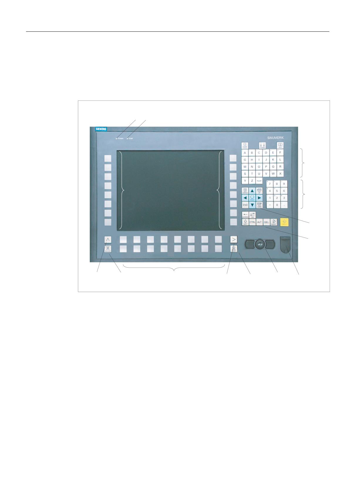
(1)
Status LED: POWER
(2)
Status LED: TEMP
Lit LEDs indicate increased wear.
(3)
Alphabetic key group
(4)
Numeric key group
(5)
Softkeys and direct keys
(6)
Cursor key group
(7)
Control key group
(8)
Front USB interface
(9)
Mouse
(10)
Menu select key
(11)
Menu forward key
(12)
Softkeys
(13)
Machine area key
(14)
Menu back key
Image 5-1
Front view of operator panel front OP 012
Operator panels
62
Manual, 03/2016, 6FC5397-1AP40-5BA3
Operator panel front: OP 012
5.2 Operator control and display elements
5.2.2
Keyboard
Keyboard
Several keys and keypads are installed on the operator panel front:
● The alphabetic block contains the letters A - Z and the space character.
● The numeric block contains the digits 0 - 9, and the characters "-", "/", "=", "+" and ".".
● The cursor key group is used to navigate on the screen.
● The control key group includes special functions.
● The mouse comprises the center actuation field (corresponds to the function of a tracker
ball) and two keys for the left and right mouse key.
● The softkeys call up functions that are available on the screen via a menu bar.
● The "Menu back" key switches back to the higher-level horizontal menu.
● The "Menu forward" key advances in the extended horizontal softkey bar.
● The "Menu select" key calls the main menu to select the operating area.
● The "Machine area" key selects the "Machine" operating area.
Switching between upper and lower case
To toggle between upper and lower case letters, press the key combination Ctrl + Shift
Upper case is always activated as standard.
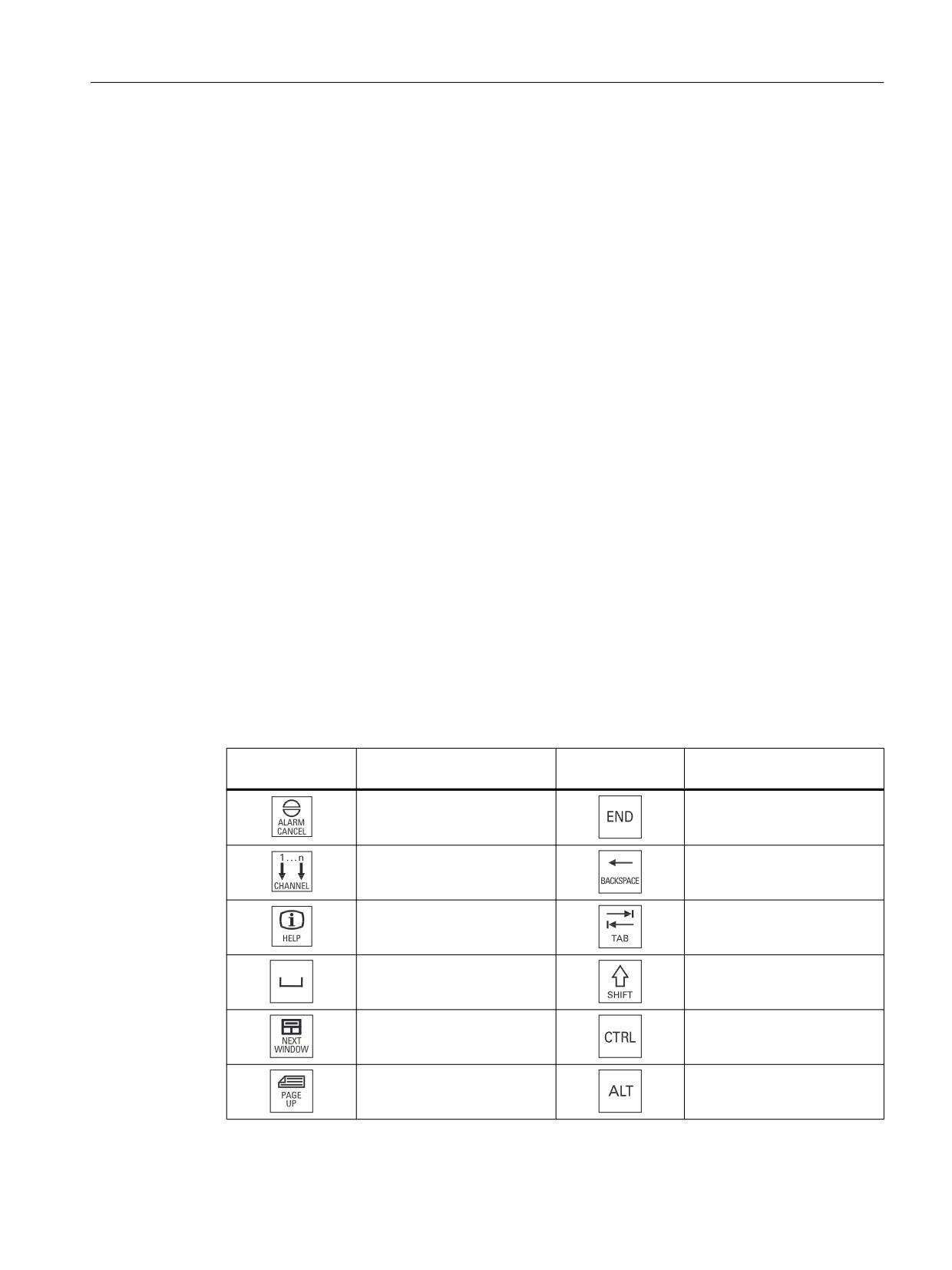
Overview of the key symbols
The key symbols used on the operator panel front are shown in the overview along with the
corresponding function keys on the PC keyboard.
Key
Function corresponds to the
Key
Function corresponds to the
PC key function
PC key function
Esc
End
F11
Backspace
F12
Tab
Space
(only intended for internal key-
board changeover)
Home
Ctrl key
Page up
Alt key
Operator panels
Manual, 03/2016, 6FC5397-1AP40-5BA3
63
Operator panel front: OP 012
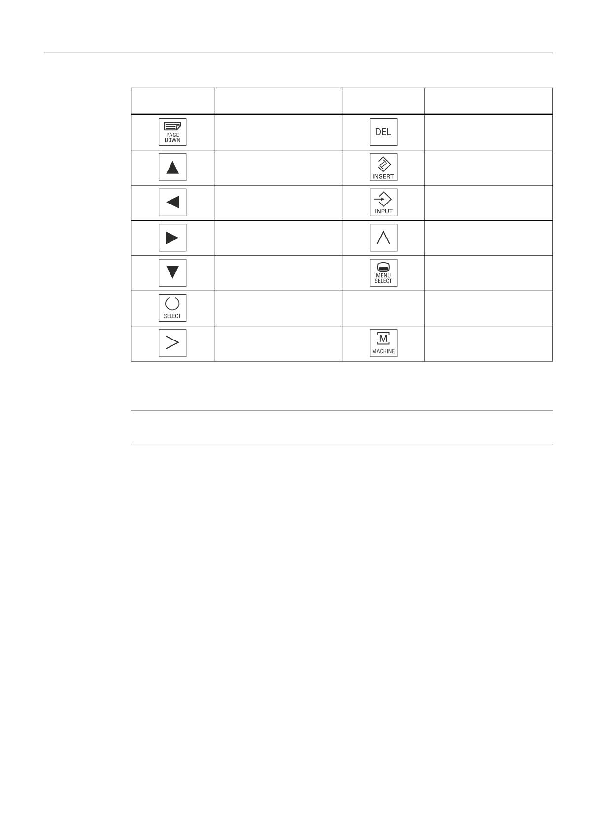
5.3 Interfaces
Key
Function corresponds to the
Key
Function corresponds to the
PC key function
PC key function
Page down
Delete
Cursor up
Insert
Cursor left
Enter
Cursor right
F9
Cursor down
F10
5 (in numeric key group)
A, ..., Z
<Shift> A, ..., Z
<Shift> F9
<Shift> F10
Display
Note
Pixel error according to DIN EN ISO 13406-2 Class II.
5.2.3
Screen saver
If a screen with high contrast is displayed unchanged for longer than an hour, the screen must
be switched dark (screensaver) in order to protect the TFT display against so-called "freezing"
of the last displayed screen.
The time can be adapted individually. Further information can be found at:
IM9 SINUMERIK Operate Commissioning Manual
5.3
Interfaces
The operator panel front has the following interfaces:
Operator panels
64
Manual, 03/2016, 6FC5397-1AP40-5BA3
Operator panel front: OP 012
5.3 Interfaces
Front side
USB 1.1 (type A) for connecting an external keyboard, mouse and USB FlashDrive (see Image
5-1 Front view of operator panel front OP 012 (Page 62)).
Note
Note that the electromagnetic compatibility of commercially available peripheral devices
operated via the USB interface is usually rated for office use only.
For industrial use, components with a higher degree of certification are recommended.
Rear side
● Two ribbon cables for connecting the PCU (see figure below):
- I/O USB cable K1 (ribbon cable):
All signals that are used for the display interface and the connection of operator panel
fronts
(e.g. supply voltages)
- Display cable K2
● Direct key interface X11 (under the cover plate); signals from the 16 "vertical softkey" direct
keys
● Interface X12 - reserved (under the cover plate)
Operator panels
Manual, 03/2016, 6FC5397-1AP40-5BA3
65
Operator panel front: OP 012
5.4 Installation
3&8
23
(1)
I/O USB cable K1
(2)
PCU main board
(3)
Cable clamp for connecting the direct key module
(4)
Keyboard controller
(5)
Direct key interface X11
(6)
Interface X12 (reserved)
(7)
Connection X14 for backlight
(8)
Connection X1 for I/O USB cable K1
(9)
Display cable K2
Image 5-2
Connections on rear of housing: Connections to the PCU
Pin assignment
For more detailed information, see "General information and networking", Chapter:
"Connecting".
See also
View (Page 62)
5.4
Installation
5.4.1
Preparation for mounting
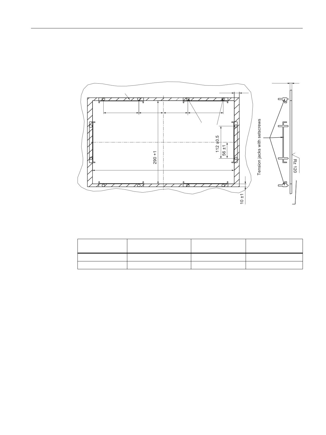
Table 5-1
Dimensions of the mounting opening
Width (mm)
Height (mm)
450
290
Operator panels
66
Manual, 03/2016, 6FC5397-1AP40-5BA3
Operator panel front: OP 012
5.4 Installation
Thanks to the tension jacks on the OP 012, drill-holes or screw holes are not needed.
This retaining method also enables the IP65 degree of protection (but only in conjunction with
a circumferential seal and when the protective USB cap is fitted).
6HDOLQJ DUHD
s
s
s
s
s
3UHVVXUH
SRLQWV
IRU WHQVLRQ
MDFNV
,Q WKH VHDOLQJ DUHD
Image 5-3
Dimension sheet for installing the OP 012 operator panel front
Table 5-2
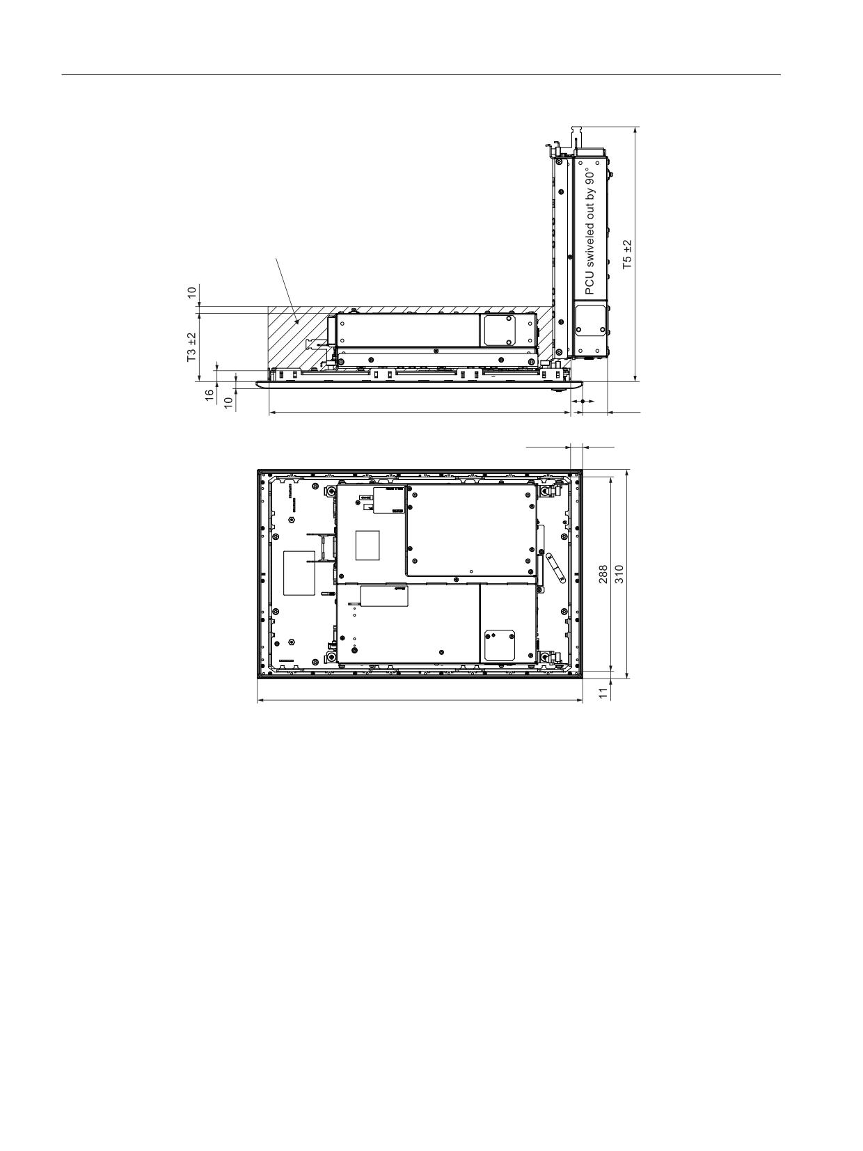
Dimensions to be observed when installing
Mounting depth T3 + clear-
Opening depth T5
Protrusion P
ance (mm)
(mm)
(mm)
PCU 50.3 / 50.5
101 + 10
377
39
TCU x0.2
50 + 10
350
-12
Operator panels
Manual, 03/2016, 6FC5397-1AP40-5BA3
67
Operator panel front: OP 012
5.4 Installation
&OHDUDQFH IRU FDEOHV DQG YHQWLODWLRQ
3&8 LQ WKH HQG SRVLWLRQ
s
s
s
Image 5-4
Dimension sheet for attaching the PCU to the OP 012 operator panel front
5.4.2
Assembling an OP 012 and a PCU
● When combining an OP 012 and PCU and possibly a direct key module, it is advisable to
assemble them prior to installation in an assembly panel.
● When combining with a PCU 50.3, you must then undo the transport lock for the hard-drive,
otherwise the system will not boot.
Operator panels
68
Manual, 03/2016, 6FC5397-1AP40-5BA3
Operator panel front: OP 012
5.4 Installation
Requirement
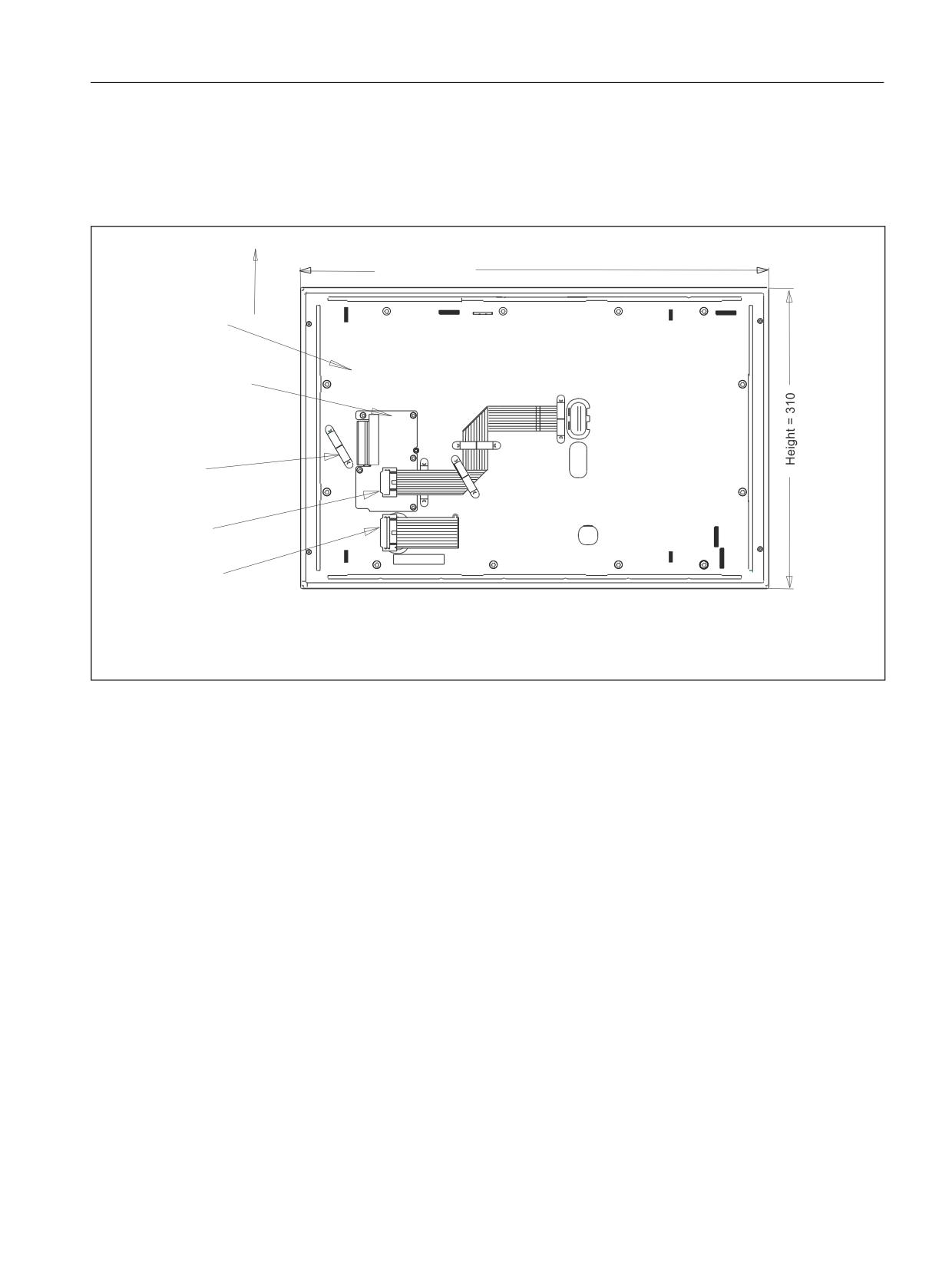
If this has not already been done, the PCU must now be bolted to the mounting brackets prior
to assembly (see the associated "PCU 50.5" manual in the Section "Installation")
:LGWK
WRS
'LVSOD\
VXSSRUW SODWH
&RYHU SODWH IRU
&RQQHFWLRQV
.H\ERDUG FRQWUROOHU
&DEOH
FODPS
'LVSOD\
FDEOH .
,2 86%
FDEOH .
0RXQWLQJ VORWV IRU 3&8 OXJV
&DEOH VKRZQ IROGHG WRJHWKHU
&DVLQJ VFUHZV
6OLW IRU VRIWNH\ ODEHOLQJ VWULSV
Image 5-5
Rear side of the OP 012
Procedure
1. Place the OP 012 face down on a flat, soft (to avoid scratches) surface.
- To install the direct control key module (see the associated manual: "Direct key module").
- Install or replace the softkey labeling strips (see Softkey labeling (Page 72))
2. Remove the PCU's interface cover.
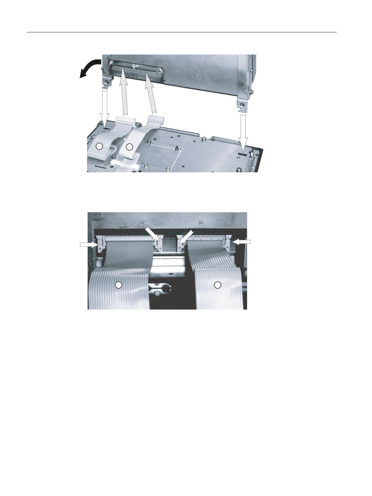
3. Place the PCU with the lugs of the bolted-on mounting brackets into the mounting slots on
the OP 012 as shown by the white arrows in diagram (A).
To make it easier to insert the lugs, it can be helpful to reduce the 90° angle between the
PCU and OP 012 by tilting the PCU as shown by the black arrow in the picture.
4. Insert the cable connectors K1 and K2 of the OP 012 into the plug connectors behind the
opening in the PCU casing (see gray arrows in diagram (A)]. Ensure that the plug
connectors lock in audibly and that the locking elements [see arrows in the diagram: (B)]
are closed.
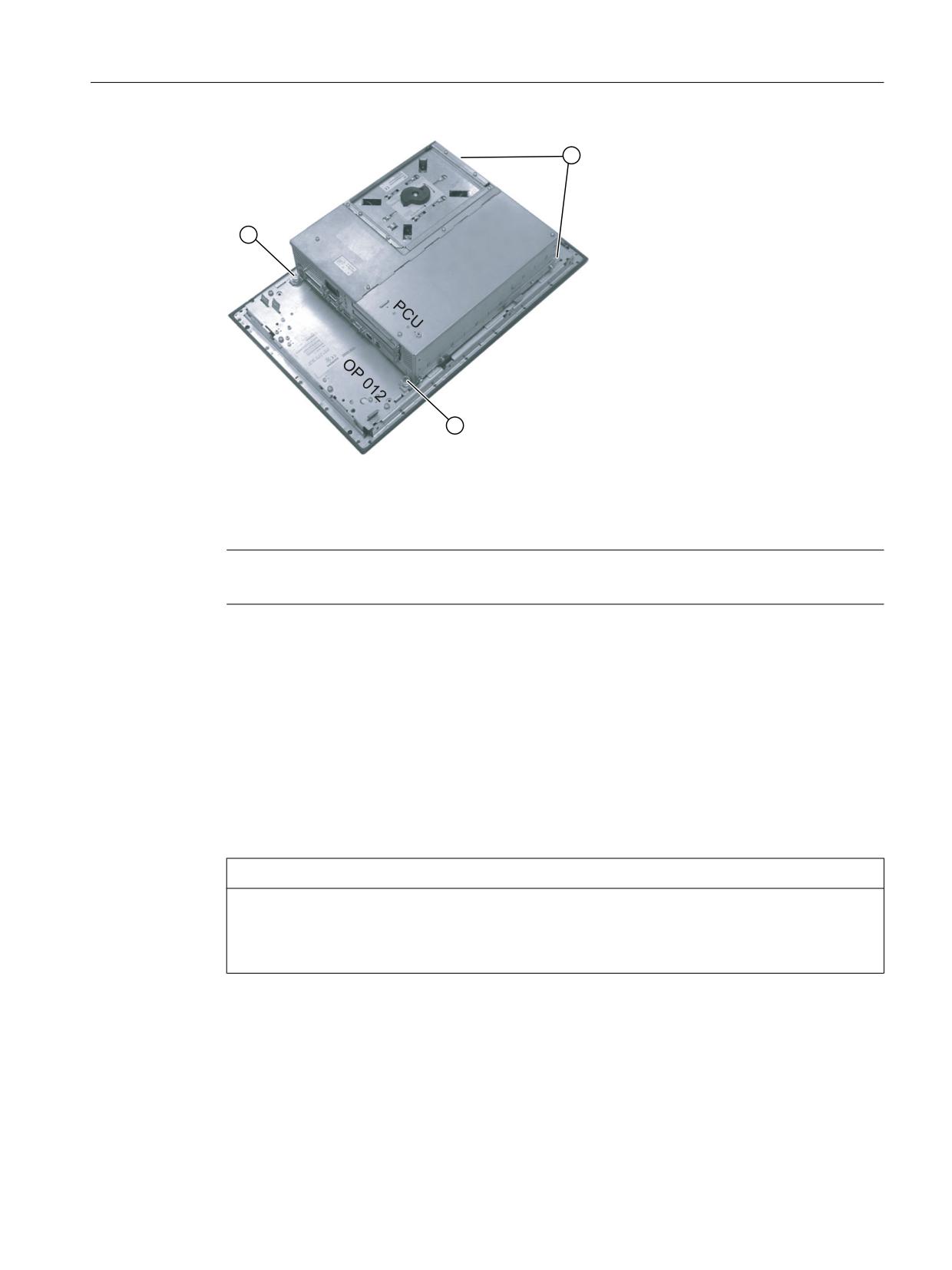
5. Swivel the PCU into its final position and secure it with knurled screws, tightening torque
of 1.8 Nm [see diagram: (C)].
Operator panels
Manual, 03/2016, 6FC5397-1AP40-5BA3
69
Operator panel front: OP 012
5.4 Installation
3&8
23
(1)
I/O / USB cable K1
(2)
Display cable K2
Image 5-6
(A) Assembling PCU and OP 012
3&8
(1)
I/O / USB cable K1
(2)
Display cable K2
Image 5-7
(B) Correct connection of IO/USB and display cables to the PCU
Operator panels
70
Manual, 03/2016, 6FC5397-1AP40-5BA3
Operator panel front: OP 012
5.4 Installation
(1)
Knurled screw
Image 5-8
(C) OP 012 and PCU after assembly
Note
The OP 010 and TCU assembly is similar to that for a PCU.
5.4.3
Mounting on the mounting wall
The clearance at the rear of the PCU/TCU must be at least 10 mm to ensure sufficient
ventilation (see Image 5-4 Dimension sheet for attaching the PCU to the OP 012 operator
panel front (Page 68)).
For more detailed information, please refer to the relevant PCU sections and in "General
information and networking", Section: "Application planning", Section: "Climatic and
mechanical environmental conditions" → "Cooling".
NOTICE
Impermissible mounting positions can cause malfunctions
Observe the permissible mounting position: Deviating by up to 5º from the vertical.
This value can be further restricted by mounted components (e.g. PCU).
Operator panels
Manual, 03/2016, 6FC5397-1AP40-5BA3
71

Operator panel front: OP 012
5.5 Technical data
Procedure
1. Insert the assembled components (operator panel front and PCU) from the front into the
panel cutout (see Image 5-3 Dimension sheet for installing the OP 012 operator panel
frontOP 012Dimension sheet (Page 67)).
2. Secure the operator panel front in the panel cutout from the rear using the tension jacks by
tightening the setscrews (torque 0.4 - 0.5 Nm).
5.4.4
Softkey labeling
User-specific functions can be assigned to the vertical softkey bars. Printed labeling strips can
be used to label the vertical softkeys.
Blank labels are already installed on delivery.
DIN A4 films are available for making the strips (for the article number, see Chapter
Overview (Page 73)).
Note
Use the "Arial" font to format text. This font is comparable to the "Univers S57" font, used by
Siemens for the key labeling.
Procedure
1. Letter the mat side of the film using a laser printer.
2. Cut the printed labels along the preprinted lines.
3. Remove the PCU retaining screws and swing out the PCU away from the operator panel
front.
4. Insert the strips into the slots provided on the rear of the operator panel front.
5. Swing the PCU back to the operator panel and secure by tightening the screws.
If the operator panel front and PCU are dismantled, omit steps 3 and 5.
5.5
Technical data
Safety
Safety class
III; PELV according to EN 50178
Degree of protection accord-
Front side IP65
ing to EN 60529
Rear side IP00
Approvals
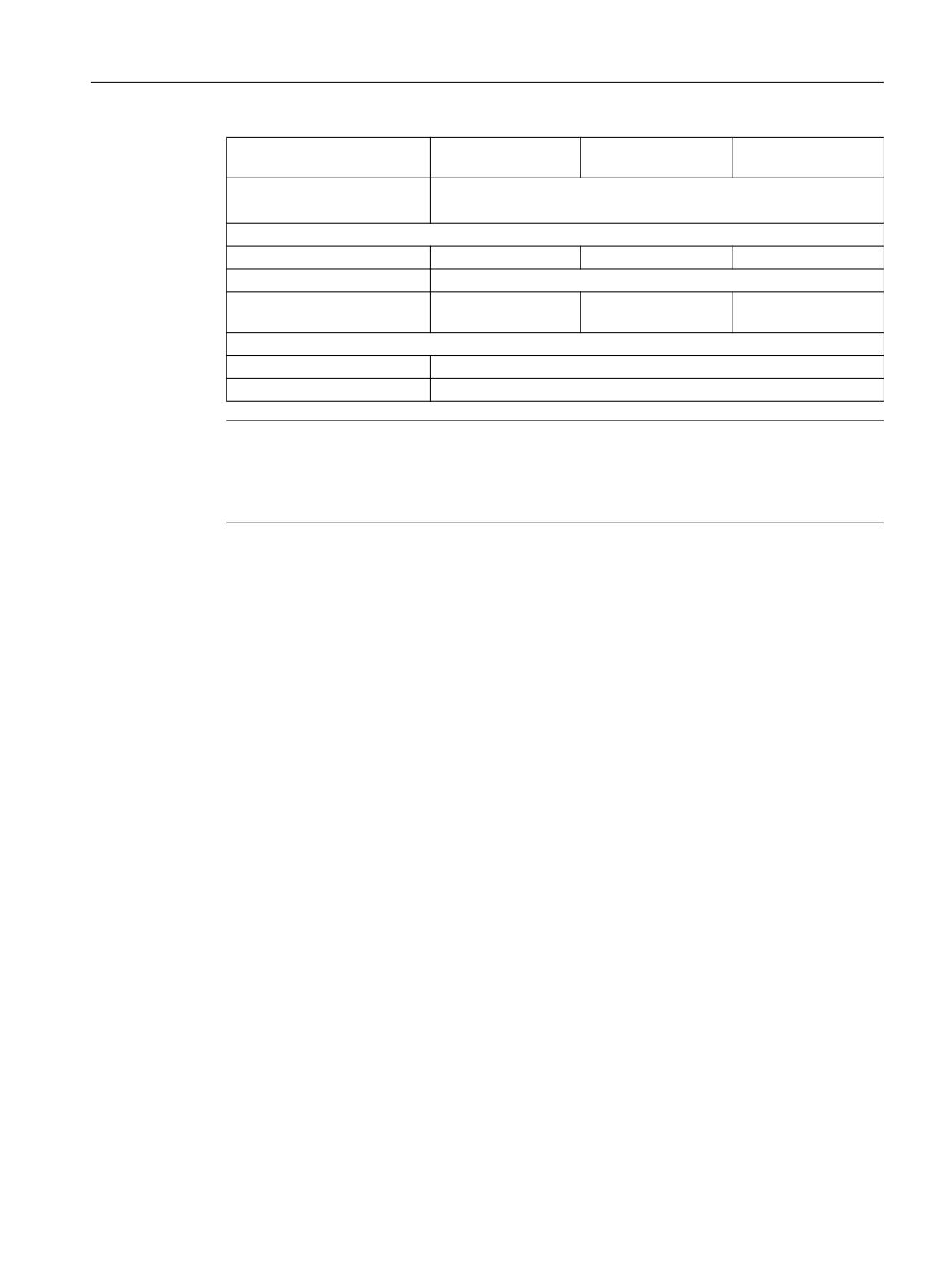
CE / cULus
Electrical data
Power supply
Display
Backlight inverter
Logic / USB
(via K1 and K2)
(with / without load)
Operator panels
72
Manual, 03/2016, 6FC5397-1AP40-5BA3
Operator panel front: OP 012
5.6 Spare parts
Voltage
5 V +/- 5%
12 V +/- 10%
5.2 V +/- 2%
Current (typ./max.)
approx. 280 / 380 mA
approx. 750 / 1000 mA
approx. 350 / 1200 mA
Power consumption
Typical, approx. 16 W
Maximum approx. 21 W
Mechanical data
Dimensions
Width: 483 mm
Height: 310 mm
Depth: 30 mm
Weight
Approx. 5 kg
Tightening torques, max.
Tension jack screws:
M3 screws:
M4 screws:
0.5 Nm
0.8 Nm
1.8 Nm
Display
Size / resolution
12.1" TFT / 800 x 600 pixels
MTBF backlight
typ. 50,000 h at 25º C (dependent on the temperature)
Note
Information about the climatic and mechanical environmental conditions is provided in the
associated section under:
"General notes and interconnection" → "Operational planning".
5.6
Spare parts
5.6.1
Overview
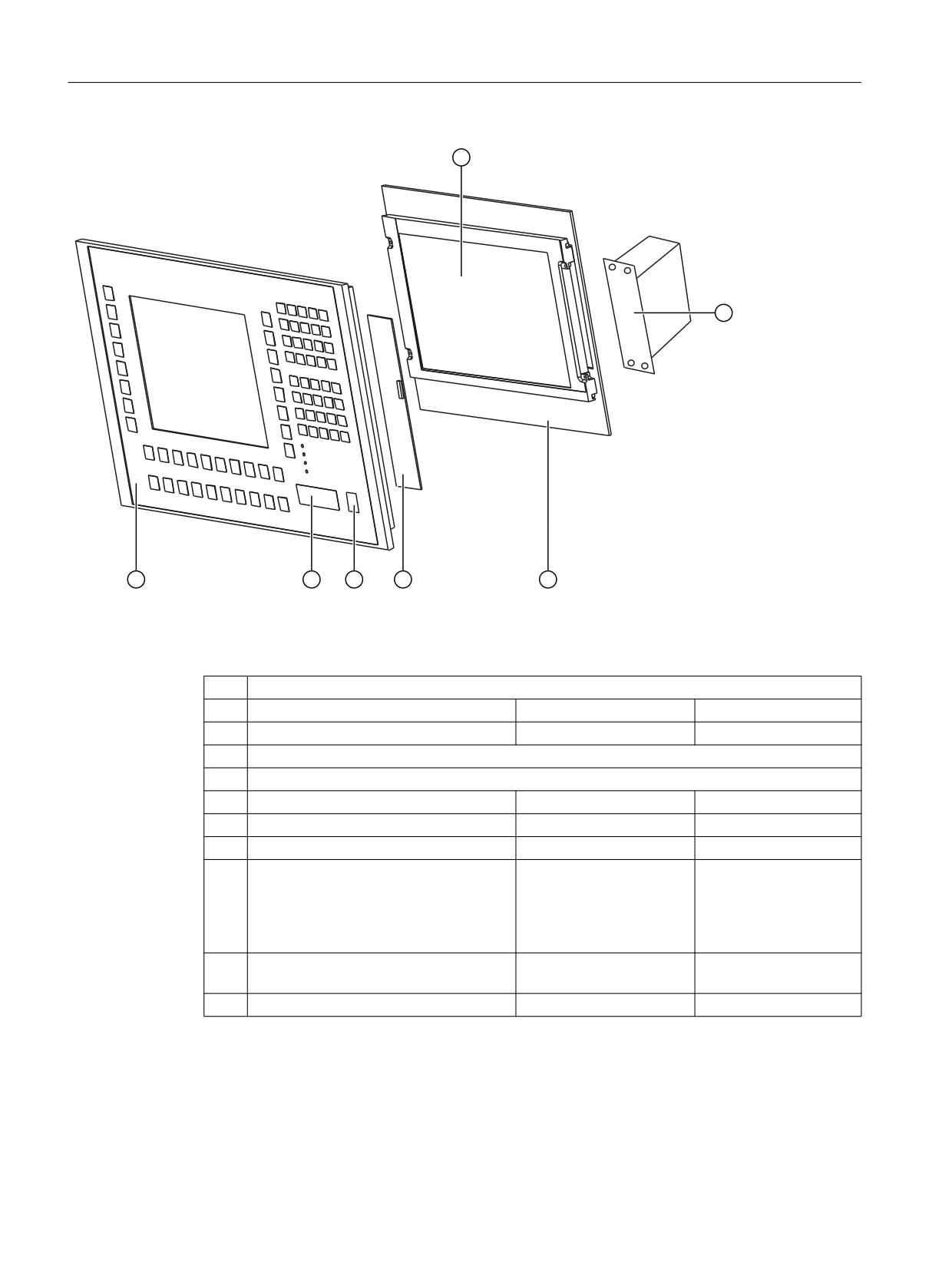
The diagram shows the OP 012 operator panel front dismantled into its individual parts.
The components provided with an order number are available as individual spare parts.
Operator panels
Manual, 03/2016, 6FC5397-1AP40-5BA3
73
Operator panel front: OP 012
5.6 Spare parts
Image 5-9
Individual parts for the OP012 operator panel front
①
Display with backlighting and backlight inverter
Spare part
Order number
Remark
②
Direct key module
6FC5247-0AF11-0AA0
③
Display support
④
Keyboard controller
⑤
Spare part
Order number
Remark
Caps for the USB port
6FC5248-0AF05-0AA0
Set of 10
⑥
USB mouse
6FC5247-0AF01-0AA0
⑦
Operator panel front
6FC5248-0AF02-0AA0
Without display, without
mouse, without key-
board controller, without
direct control key mod-
ule
Inscribable slide-in labels*)
6FC5248-0AF08-0AA0
Set of 3
(DIN A4 films)
Tension jacks
6FC5248-0AF06-0AA0
Set of 6
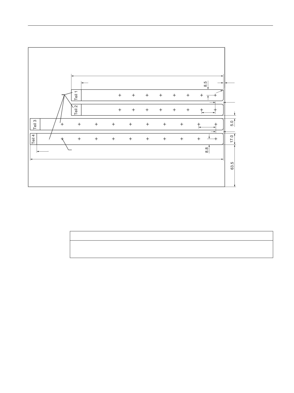
*) The dimensions for production of slide-in film labels for softkey labeling can be seen in the
following diagram.
Operator panels
74
Manual, 03/2016, 6FC5397-1AP40-5BA3
Operator panel front: OP 012
5.6 Spare parts
5
6OLGH LQ ODEHOV
&HQWHU RI WKH NH\
Image 5-10 Dimensions for DIN A4 film
5.6.2
Replacement
NOTICE
Risk of damage to sensitive components due to static electricity
Spare parts must always be replaced by properly trained personnel!
USB cap / tension jack
The replacement of the USB sealing cap and tension jacks will not be described since it is
simple and self-explanatory.
Film labels
The procedure for replacement is described in Section: "Softkey labels".
Operator panels
Manual, 03/2016, 6FC5397-1AP40-5BA3
75
Operator panel front: OP 012
5.6 Spare parts
Operator panel front/mouse
When replacing the operator panel front, the previous mouse, LCD unit and keyboard controller
can be used again. They are therefore disassembled and reassembled after the appropriate
component has been replaced.
This description is therefore valid for both the operator panel front and the mouse.
Note
We recommend reusing the keypad controller to prevent any loss of the control parameters
that have been programmed in.
Procedure
1. Put the OP 012 face down on a flat, soft surface and loosen the 12 housing screws (see
Figure: "OP 012", Section: "Assembling the OP 012 and PCU").
2. Remove the softkey labeling strips and the cover plate.
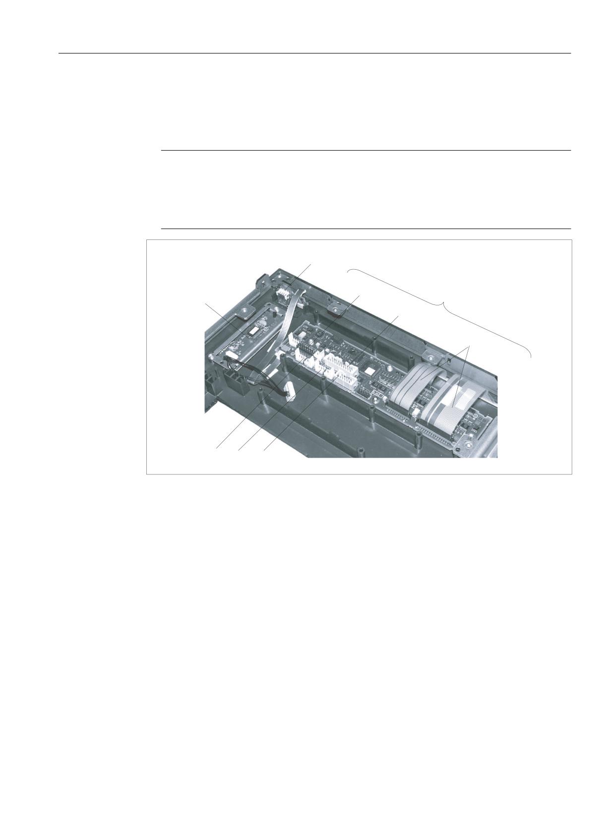
3. Remove connector X14 for the backlight and the IO-USB cable K1 from the keyboard
controller (see following Figure).
4. Lift off the display support and the display.
In addition to the keyboard controller, the rear sides of the mouse and USB interface
become visible.
5. After bending back the two lugs, withdraw the USB interface.
6. Disconnect the three membrane connectors of the operator panel front keyboard from
sockets X7, X8 and X10 (Procedure: see Note).
7. Remove the fastening screws from the mouse and keyboard controller.
Operator panels
76
Manual, 03/2016, 6FC5397-1AP40-5BA3
Operator panel front: OP 012
5.6 Spare parts
8. Lift USB interface, mouse and keyboard controller off the front plate. The interconnections
may remain plugged.
9. Install the components into the new operator front panel in reverse order (procedure: see
Note).
Note
Descriptions of how to disconnect and connect the membrane connector can be found in
"General information and networking", Chapter: "Connecting", Section: "Handling
membrane connectors".
When tightening the screws, observe the torques (refer to Section: "Technical data").
(1)
Mouse
(2)
USB interface
(3)
Keyboard controller
(4)
Connection X1 for IO-USB cable K1
(5)
Direct key connection X11
(6)
Membrane connector for connecting the keyboard of the operator panel front
(7)
Connection X12 (reserved)
(8)
Connection X14 for backlight
(9)
Connection X4 for mouse
Image 5-11 Replacement of operator panel front OP 012
Operator panels
Manual, 03/2016, 6FC5397-1AP40-5BA3
77
Operator panel front: OP 012
5.6 Spare parts
Operator panels
78
Manual, 03/2016, 6FC5397-1AP40-5BA3
Operator panel front: OP 015
6
6.1
Description
The SINUMERIK OP 015 operator panel front and 15" TFT color display with a resolution of
1024 x 768 pixels (XGA) features 8 +4 horizontal and 8 vertical membrane softkeys.
The KB 483C full CNC keyboard can be used as an input keyboard.
It is fixed from the rear using special clamps that are included in the delivery scope.
Validity
The description below applies to the OP 015 operator panel front.
Article number 6FC5203-0AF03-0AA0
Features
●
19" mounting format, 7 HU (height units)
● Panel cutout (W x H): 450 x 290 mm
● Limited mounting depth
●
15" TFT flat screen (color) with resolution 1024 x 768 pixels
● Membrane keyboard:
-
8 + 4 horizontal softkeys
–
8 vertical softkeys
● Status LEDs for power supply and overtemperature
● Front USB interface
● Degree of protection: IP65
● Attachment: Tension jacks at the rear
● Can be combined with PCU, TCU
Operator panels
Manual, 03/2016, 6FC5397-1AP40-5BA3
79
Operator panel front: OP 015
6.2 Operating and display elements
6.2
Operating and display elements
6.2.1
View
① Status LED: POWER
② Status LED: TEMP
Lit LEDs indicate increased wear.
③ Softkeys
④ Menu select key
⑤ Menu forward key
⑥ Softkeys
⑦ Menu back key
⑧ Machine area button
⑨ Front USB interface
Image 6-1
View of operator panel front OP 015
6.2.2
Keyboard
Keyboard
Several keys are arranged on the operator panel front:
● The eight vertical and horizontal softkeys call up functions that are available on screen via
a menu bar.
● The "Menu back" key switches back to the higher-level horizontal menu.
Operator panels
80
Manual, 03/2016, 6FC5397-1AP40-5BA3
Operator panel front: OP 015
6.3 Interfaces
● The "Menu forward" key advances in the extended horizontal softkey bar.
● The "Menu select" key calls the main menu to select the operating area.
● The "Machine area" key selects the "Machine" operating area.
The key symbols used on the operator panel front are shown below along with the
corresponding function keys on the PC keyboard.
Key
Function corresponds to
Key
Function corresponds to the
the PC key function
PC key function
<Shift> F9
F9
<Shift> F10
F10
Display
Note
Pixel error according to DIN EN ISO 13406-2 Class II.
6.2.3
Screen saver
If a screen with high contrast is displayed unchanged for longer than an hour, then the
screensaver must be activated in order to protect the TFT display against so-called "burning
in" of the last displayed screen.
The time can be adapted individually. Further information can be found at:
Commissioning of Basic Software and Operating Software, SINUMERIK Operate (IM9)
6.3
Interfaces
Front
USB 1.1 Full Speed (type A) for connecting an external keyboard, mouse and USB flash drive
(see Image 6-1 View of operator panel front OP 015 (Page 80)).
Note
Note that the electromagnetic compatibility of commercially available peripheral devices
operated via the USB interface is usually rated for office use only.
For industrial use, components with a higher degree of certification are recommended.
Operator panels
Manual, 03/2016, 6FC5397-1AP40-5BA3
81
Operator panel front: OP 015
6.4 Mounting
Rear
● Two flat ribbon cables for connecting the PCU:
- I/O USB cable K1 ②:
All signals that are used for the display interface and the connection of operator panel
fronts (e.g. supply voltages)
- Display cable K2 ①
3&8
23
Image 6-2
Connections on rear of housing Connections to the PCU
Pin assignment
For more detailed information, see "General information and networking", Chapter:
"Connecting".
6.4
Mounting
6.4.1
Preparation for mounting
Table 6-1
Dimensions of the mounting opening
Width (mm)
Height (mm)
450
290
Thanks to the tension jacks on the OP 015, drill-holes or screw holes are not needed.
This retaining method also enables the IP65 degree of protection (but only in conjunction with
a circumferential seal and when the protective USB cap is fitted).
Operator panels
82
Manual, 03/2016, 6FC5397-1AP40-5BA3
Operator panel front: OP 015
6.4 Mounting
6HDOLQJ DUHD
s
3UHVVXUH SRLQWV
IRU WHQVLRQ MDFNV
,Q WKH VHDOLQJ DUHD
Image 6-3
Dimension drawing for mounting the OP015 operator panel front
Table 6-2
Dimensions to be observed when installing
Mounting depth T3 + clear-
Opening depth T5
Protrusion P
ance (mm)
(mm)
(mm)
PCU 50.5
125 + 10
402
21
TCU x0.2
75 + 10
376
-30
Operator panels
Manual, 03/2016, 6FC5397-1AP40-5BA3
83
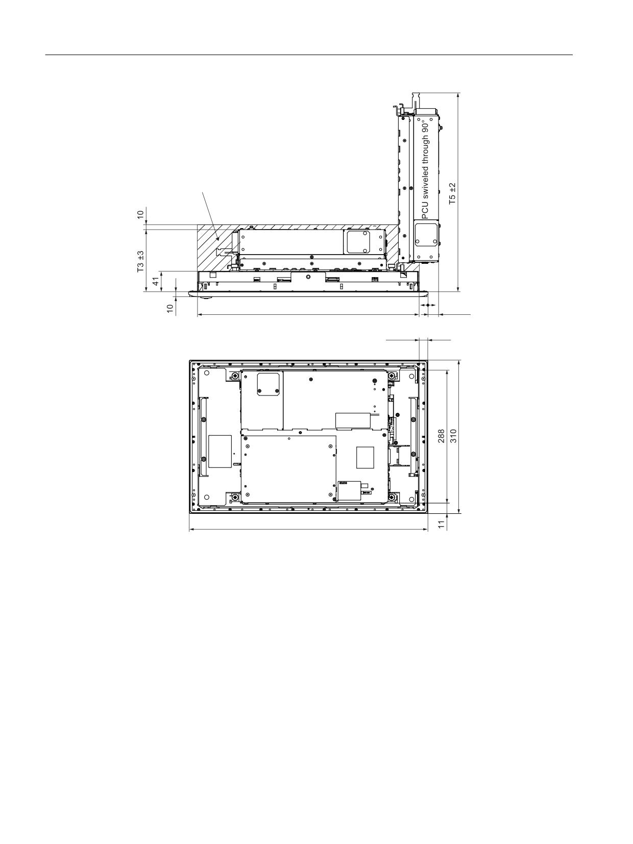
Operator panel front: OP 015
6.4 Mounting
6SDFH IRU FDEOHV DQG YHQWLODWLRQ
3&8 LQ ILQDO SRVLWLRQ
s
s
s
Image 6-4
Dimension drawing for attaching the PCU to the OP015 operator panel front
6.4.2
Assembling an OP 015 and a PCU
When combining an OP 015 and PCU, it is advisable to assemble them prior to installation in
an assembly panel.
Procedure
To do this, proceed as described in Section: "OP 012", Section: "Assembling the OP 012 and
PCU."
Operator panels
84
Manual, 03/2016, 6FC5397-1AP40-5BA3
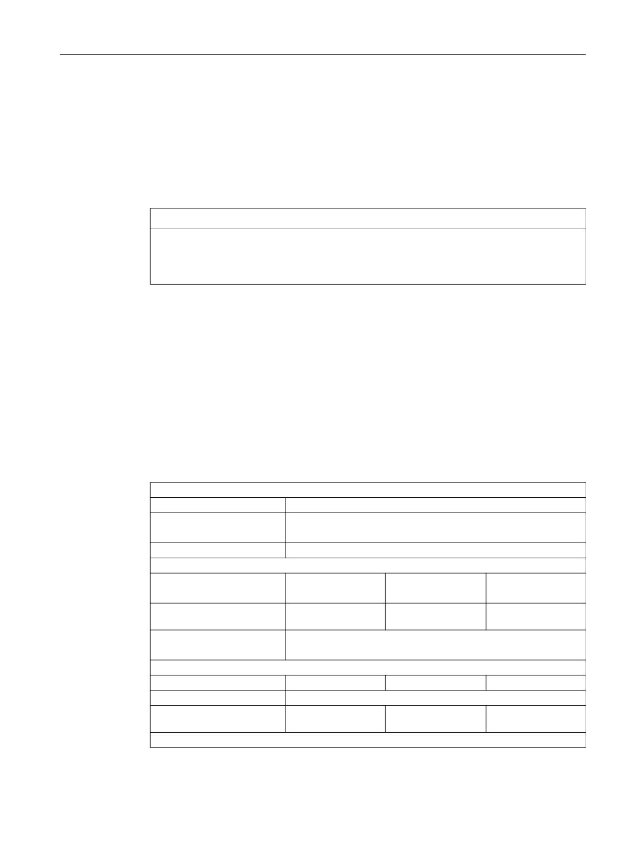
Operator panel front: OP 015
6.5 Technical data
6.4.3
Mounting on the mounting wall
The clearance at the rear of the PCU/TCU must be at least 10 mm to ensure sufficient
ventilation (see Image 6-4 Dimension drawing for attaching the PCU to the OP015 operator
panel front (Page 84)).
For more detailed information, please refer to the relevant PCU sections and in "General
information and networking", Section: "Application planning", Section: "Climatic and
mechanical environmental conditions" → "Cooling".
NOTICE
Impermissible mounting positions can cause malfunctions
Observe the permissible mounting position: Deviating by up to 5º from the vertical.
This value can be further restricted by mounted components (e.g. PCU).
Procedure
1. Insert the assembled components (operator panel front and PCU) from the front into the
panel cutout (see Image 6-3 Dimension drawing for mounting the OP015 operator panel
front (Page 83)).
2. Secure the operator panel front in the panel cutout from the rear using the six tension jacks
by tightening the setscrews (torque 0.4 - 0.5 Nm).
6.5
Technical data
Safety
Safety class
III; PELV according to EN 50178
Degree of protection accord-
Front side IP65
ing to EN 60529
Rear side IP00
Approvals
CE / cULus
Electrical data
Power supply
Display
Backlight inverter
Logic / USB
(via K1 and K2)
(with / without load)
Voltage
5 V +/- 5%
12 V +/- 10%
5.2 V +/- 2%
Current (typ./max.)
approx. 420/600 mA
approx. 900/1050 mA
approx. 350/1000 mA
Power consumption
Typical, approx. 15 W
Maximum approx. 24 W
Mechanical data
Dimensions
Width: 483 mm
Height: 310 mm
Depth: 52 mm
Weight
approx. 7 kg
Tightening torques, max.
Tension jack screws:
M3 screws:
M4 screws:
0.5 Nm
0.8 Nm
1.8 Nm
Display
Operator panels
Manual, 03/2016, 6FC5397-1AP40-5BA3
85
Operator panel front: OP 015
6.6 Spare parts
Size / resolution
15" TFT / 1024 x 768 pixels
MTBF backlight
typ. 40,000 h at 25º C (dependent on the temperature)
Note
Information about the climatic and mechanical environmental conditions is contained in the
associated section under:
"General notes and interconnection" → "Operational planning".
6.6
Spare parts
6.6.1
Overview
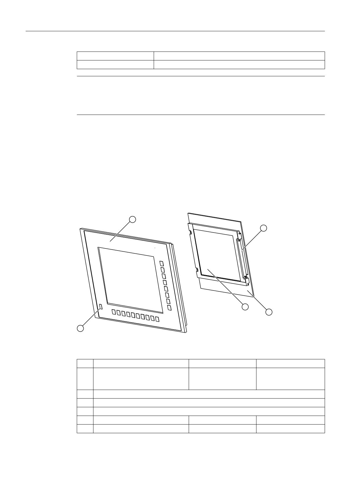
The diagram shows the OP 015 operator panel front dismantled into its individual parts.
The components listed with an article number are available as spare parts.
Image 6-5
Individual parts for the OP 015 operator panel front
Spare part
Article number
Remark
①
Operator panel front
6FC5248-0AF03-0AA0
Without LCD unit, USB
port and keyboard control-
ler
②
Background lighting with backlight inverter
③
Display support with keyboard controller (rear)
④
LCD unit
⑤
Caps for the USB port
6FC5248-0AF05-0AA0
Set of 10
Tension jacks
6FC5248-0AF06-0AA0
Set of 6
Operator panels
86
Manual, 03/2016, 6FC5397-1AP40-5BA3
Operator panel front: OP 015
6.6 Spare parts
6.6.2
Replacement
NOTICE
Risk of damage to sensitive components due to static electricity
Spare parts must always be replaced by properly trained personnel!
USB cap / tension jack
The replacement of the USB sealing cap and tension jacks will not be described since it is
simple and self-explanatory.
Operator panel front
When changing the operator panel front, the existing USB interface and the display support
(with display, backlight inverter and keyboard controller) can be reused. They are therefore
disassembled and reassembled after the appropriate component has been replaced.
Note
We recommend reusing the keypad controller to prevent any loss of the control parameters
that have been programmed in.
Operator panels
Manual, 03/2016, 6FC5397-1AP40-5BA3
87
Operator panel front: OP 015
6.6 Spare parts
Procedure
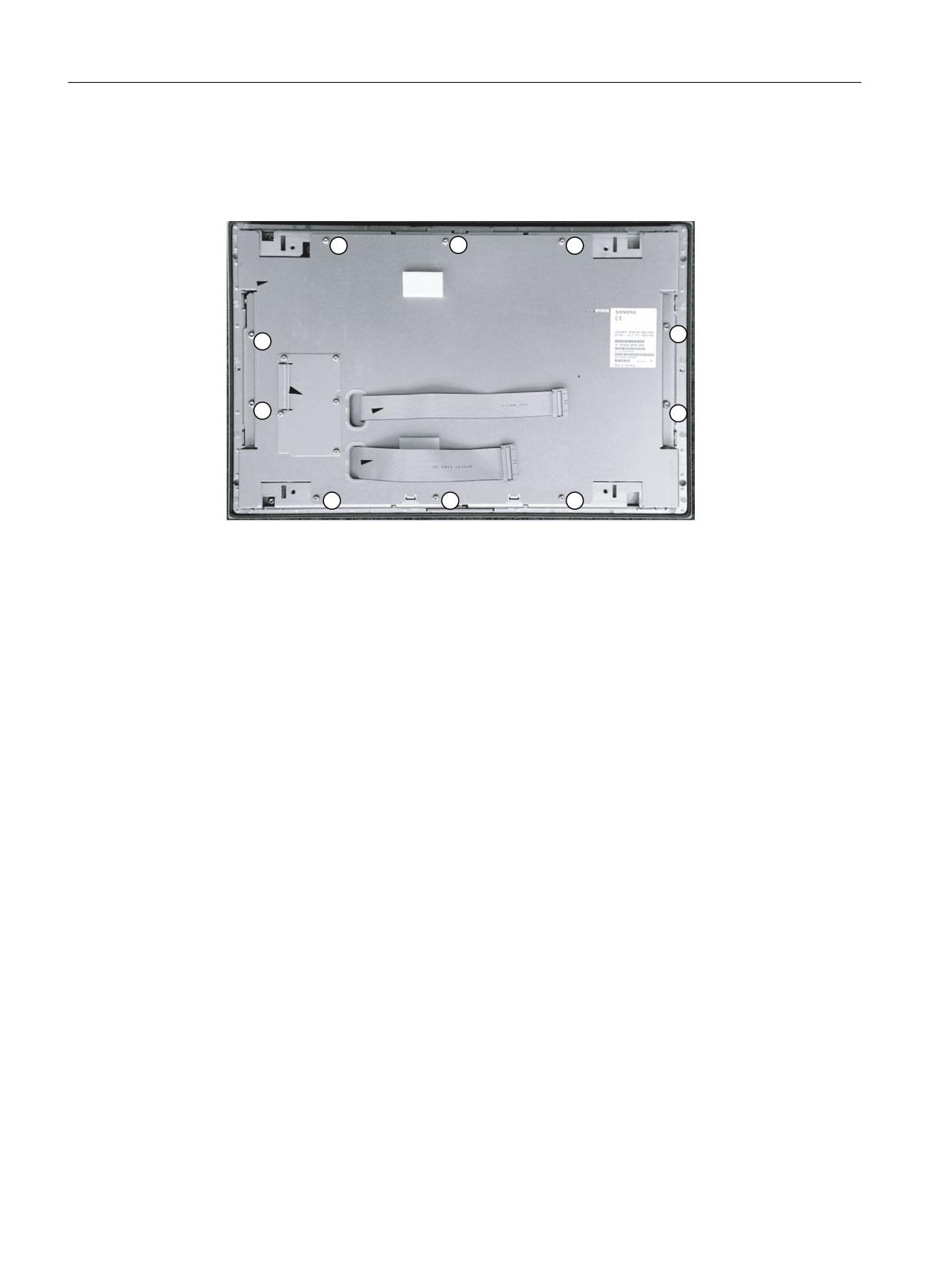
1. Put the OP 015 and the replacement operator panel front face down on a flat, soft surface.
2. Remove the housing screws and the housing cover plate.
① M3 housing screws
② M4 housing screws
Image 6-6
Rear of the OP 015
The display support with the keyboard controller is visible underneath and, in a cutout of
the mounting plate, the rear side of the USB interface.
Operator panels
88
Manual, 03/2016, 6FC5397-1AP40-5BA3
Operator panel front: OP 015
6.6 Spare parts
3. Disconnect the membrane connectors of the operator panel front keyboard from sockets
X7, X8 and X10.
① I/O USB cable K1
② Connection X11 (reserved)
③ Membrane lines from the operator panel front keyboard
④ X7
⑤ X8
⑥ X10
⑦ Connection X12 (reserved)
⑧ Display cable K2
⑨ USB membrane line
⑩ Connection X14 for display and backlight
⑪ Connection X4 (reserved)
Image 6-7
Keyboard controller
Note
Descriptions of how to disconnect and connect the membrane connector can be found in
"General information and networking", Chapter: "Connecting", Section: "Handling
membrane connectors".
When tightening the screws, observe the torques (see Technical data (Page 85)).
Operator panels
Manual, 03/2016, 6FC5397-1AP40-5BA3
89
Operator panel front: OP 015
6.6 Spare parts
4. Remove the membrane connector of the USB connecting cable.
① Display support
② USB membrane cable (refer to the diagram above)
③ USB interface
④ Fastening screw M4
Image 6-8
USB interface viewed from the operator panel rear side
5. Remove the screws of the display support and lift it off.
6. Pull the USB interface off its seat and insert it into the replacement operator panel front.
7. Place the display support on the replacement operator panel front.
8. Assemble the operator panel front in reverse order.
Operator panels
90
Manual, 03/2016, 6FC5397-1AP40-5BA3
Operator panel front: OP 015A
7
7.1
Description
The SINUMERIK OP 015A operator panel front and 15" TFT color display with a resolution of
1024 x 768 pixels (XGA) features a 62-key membrane keyboard with 2 x (8 + 2) horizontal and
2 x 8 vertical softkeys and an integral mouse. The 2 x 8 vertical softkeys can be used as direct
keys.
The operator panel front is secured from the rear using special clamps supplied with the panel.
Validity
The description below applies to the OP 015A operator panel front
Article number 6FC5203-0AF05-0AB0
Features
●
19" mounting format, 8 HU (height units)
● Panel cutout (W x H): 450 x 335 mm
● Limited mounting depth
●
15" TFT flat screen (color) with resolution 1024 x 768 pixels
● Membrane keyboard with alphabetic, numeric, cursor, and control keypad
● Softkeys / direct keys:
-
2 x (8 + 2) horizontal rows of keys with softkey function
–
2 x 8 vertical rows of keys with softkey and direct key functions
– Direct keys connectable via direct key / handwheel connection module or MCP interface
PN (optional), machine control panel, TCU or directly to the I/Os
● Shift key for switchover to the second key level (not for switching over the letters, since
they are uppercase only)
● Integrated mouse
● Status LEDs for power supply and overtemperature
● USB front interface (USB 1.1 Full Speed)
● Degree of protection IP65 (front)
● Attachment: Tension jacks at the rear
● Can be combined with PCU, TCU
Operator panels
Manual, 03/2016, 6FC5397-1AP40-5BA3
91
Operator panel front: OP 015A
7.2 Operating and display elements
7.2
Operating and display elements
7.2.1
View
① Status LED POWER
② Status LED TEMP: Lit LEDs indicate increased wear.
③ Softkeys and direct keys
④ Alphabetic key group
⑤ Numeric key group
⑥ Cursor key group
⑦ Control key group
⑧ Mouse
⑨ Menu forward key
⑩ Menu select key
⑪ Softkeys
⑫ Machine area button
⑬ Menu back key
⑭ Front USB interface
Image 7-1
Front view of the OP 015A operator panel front
Operator panels
92
Manual, 03/2016, 6FC5397-1AP40-5BA3
Operator panel front: OP 015A
7.2 Operating and display elements
7.2.2
Keyboard
Keyboard
Several keys and keypads are installed on the operator panel front:
● The alphabetic block contains the letters A - Z and the space character.
● The numeric block contains the digits 0 - 9, and the characters "-", "/", "=", "+" and ".".
● The cursor key group is used to navigate on the screen.
● The control key group includes special functions.
● The mouse comprises the center actuation field (corresponds to the function of a tracker
ball) and two keys for the left and right mouse key.
● The softkeys call up functions that are available on the screen via a menu bar.
● The menu select key displays the area menu.
● The menu forward key enables an expansion of the horizontal softkey bar in the same menu.
● The machine area key switches directly into the "Machine" operating area.
● The menu back key returns to the higher-level menu, one window is closed.
Switching between upper and lower case
To toggle between upper and lower case letters, press the key combination Ctrl + Shift
Upper case is always activated as standard.
Overview of the key symbols
The key symbols used on the operator panel front are shown below along with the
corresponding function keys on the PC keyboard.
Key
Function corresponds to the
Key
Function corresponds to the
PC key function
PC key function
Esc
End
F11
Backspace
F12
Tab
Space
(only intended for internal key-
board changeover)
Home
Ctrl key
Page up
Alt key
Operator panels
Manual, 03/2016, 6FC5397-1AP40-5BA3
93
Operator panel front: OP 015A
7.3 Interfaces
Key
Function corresponds to the
Key
Function corresponds to the
PC key function
PC key function
Page down
Delete
Cursor up
Insert
Cursor left
Enter
Cursor right
F9
Cursor down
F10
5 (in numeric key group)
A, ..., Z
<Shift> A, ..., Z
<Shift> F9
<Shift> F10
Display
Note
Pixel error according to DIN EN ISO 13406-2 Class II.
7.2.3
Screen saver
If a screen with high contrast is displayed unchanged for longer than an hour, then the
screensaver must be activated in order to protect the TFT display against so-called "burning
in" of the last displayed screen.
The time can be adapted individually. Further information can be found at:
Commissioning of Basic Software and Operating Software, SINUMERIK Operate (IM9)
7.3
Interfaces
The OP 015 operator panel front has the following interfaces:
Operator panels
94
Manual, 03/2016, 6FC5397-1AP40-5BA3
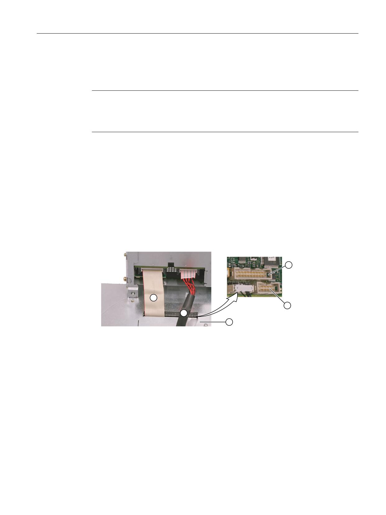
Operator panel front: OP 015A
7.3 Interfaces
Front
USB 1.1 Full Speed (type A) for connecting an external keyboard, mouse and USB flash drive
(see Image 7-1 Front view of the OP 015A operator panel front (Page 92)).
Note
Note that the electromagnetic compatibility of commercially available peripheral devices
operated via the USB interface is usually rated for office use only.
For industrial use, components with a higher degree of certification are recommended.
Rear
● Two cables for connecting the PCU:
- I/O USB cable K1 ⑤:
All signals that are used for the display interface and the connection of operator panel
fronts (e.g. supply voltages)
- Display cable K2 ④
Below the interface cover ③:
● Direct key interface X11 ①: Signals from the 16 "vertical softkey" direct keys
● Interface X12 (reserved) ②
Image 7-2
OP015A - Connections on rear of housing: Connections to the PCU
Pin assignment
For more detailed information, see "General information and networking", Chapter:
"Connecting".
Operator panels
Manual, 03/2016, 6FC5397-1AP40-5BA3
95
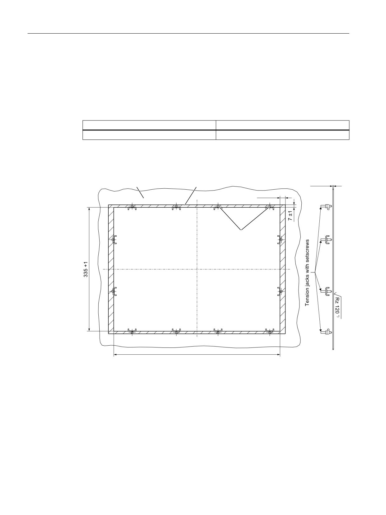
Operator panel front: OP 015A
7.4 Mounting
7.4
Mounting
7.4.1
Preparation for mounting
Table 7-1
Dimensions of the mounting opening
Width (mm)
Height (mm)
450
335
Thanks to the tension jacks on the OP 015A, drill-holes or screw holes are not needed.
This retaining method also enables the IP65 degree of protection (but only in conjunction with
a circumferential seal and when the protective USB cap is fitted).
0RXQWLQJ SDQHO
6HDOLQJ DUHD
s
3UHVVXUH SRLQWV IRU
WHQVLRQ MDFNV
,Q WKH VHDOLQJ DUHD
Image 7-3
Dimension sheet for installing the OP 015A operator panel front
7.4.2
Assembling an OP 015A and a PCU
If you want to combine the OP 015A with a PCU and possibly a direct key module (see Section:
"Direct key module"), assemble the components before installing them on the mounting wall.
Operator panels
96
Manual, 03/2016, 6FC5397-1AP40-5BA3
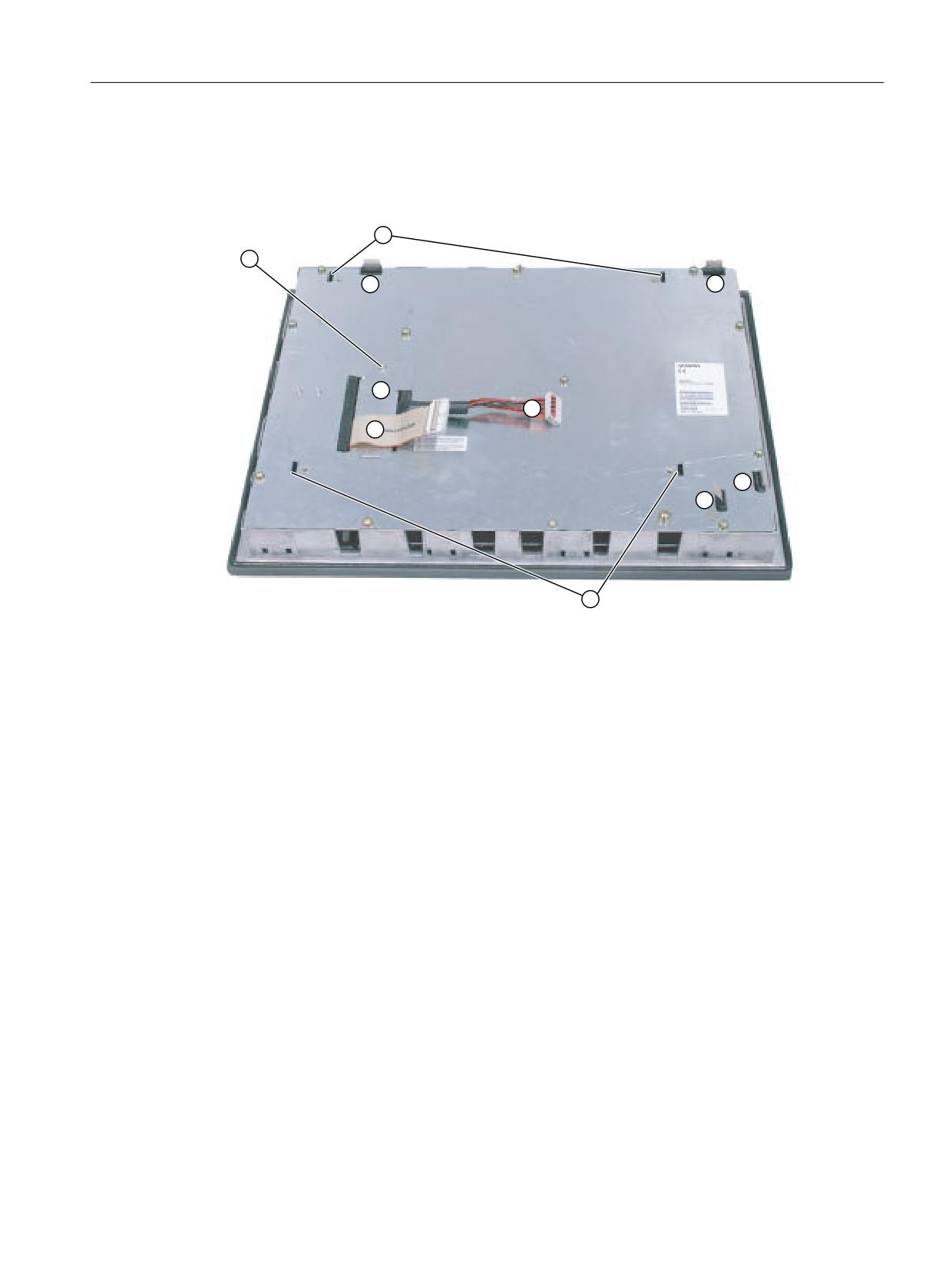
Operator panel front: OP 015A
7.4 Mounting
Requirement
The PCU must now be bolted to the mounting brackets prior to assembly (if this has not already
been done), see Assembly of PCU and operator panel front (standard mounting) (Page 234))
① Mounting slots for PCU lugs
② Slots for inserting softkey labeling strips
③ Display cable K2
④ I/O / USB cable K1
⑤ Cover plate for keyboard controller connections
⑥ Retaining screw for the cover plate
Image 7-4
OP 015A rear side
Operator panels
Manual, 03/2016, 6FC5397-1AP40-5BA3
97
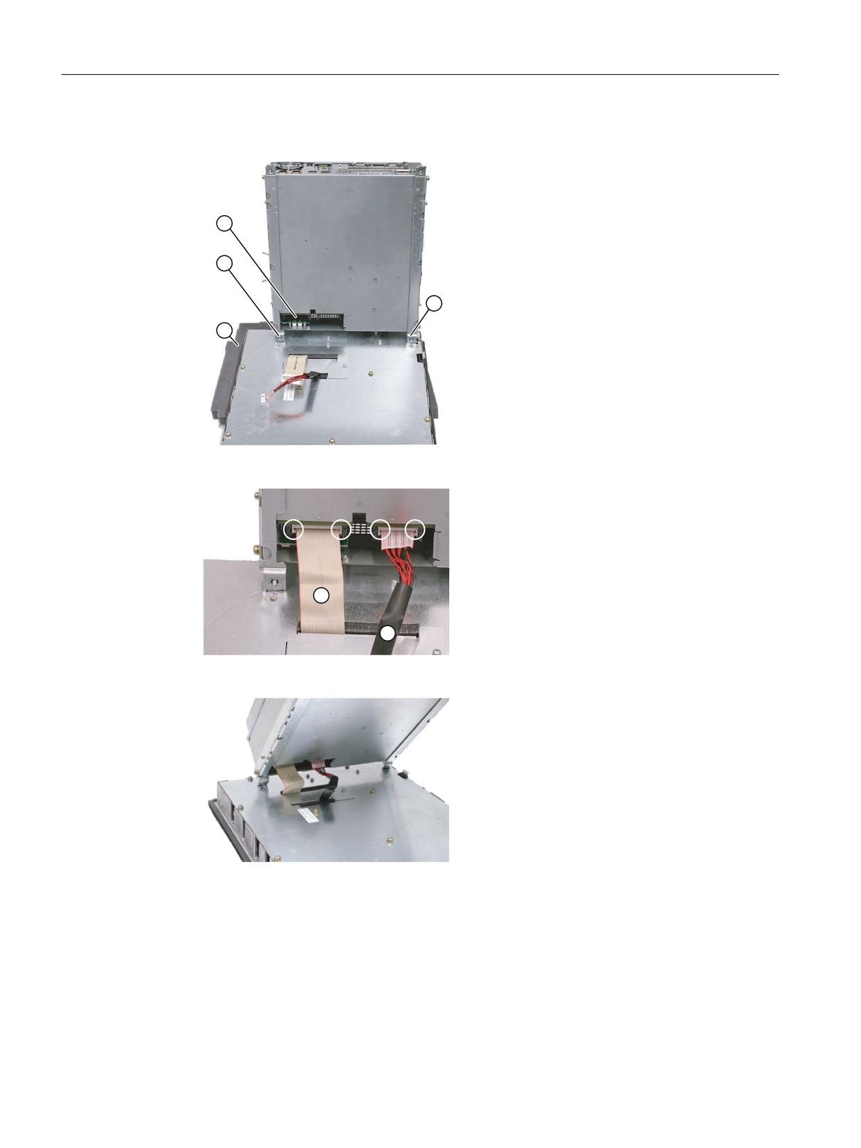
Operator panel front: OP 015A
7.4 Mounting
Procedure
1. Place the front of the OP 015A on a soft,
horizontal surface ③ to avoid damaging
3&8
the surface of the operator panel front.
2. Remove the interface cover ① of the PCU.
3. Position the PCU so that the mounting lugs
② engage in the OP 015A.
4. Connect cable connectors K1 ① and K2
② to the interfaces of the PCU.
5. Make sure that you hear the connectors
lock in and that the locks are closed (see
marked rings)
6. Swivel the PCU in the direction of the
OP 015A and make sure that the cables
fold correctly into place.
Operator panels
98
Manual, 03/2016, 6FC5397-1AP40-5BA3
Operator panel front: OP 015A
7.4 Mounting
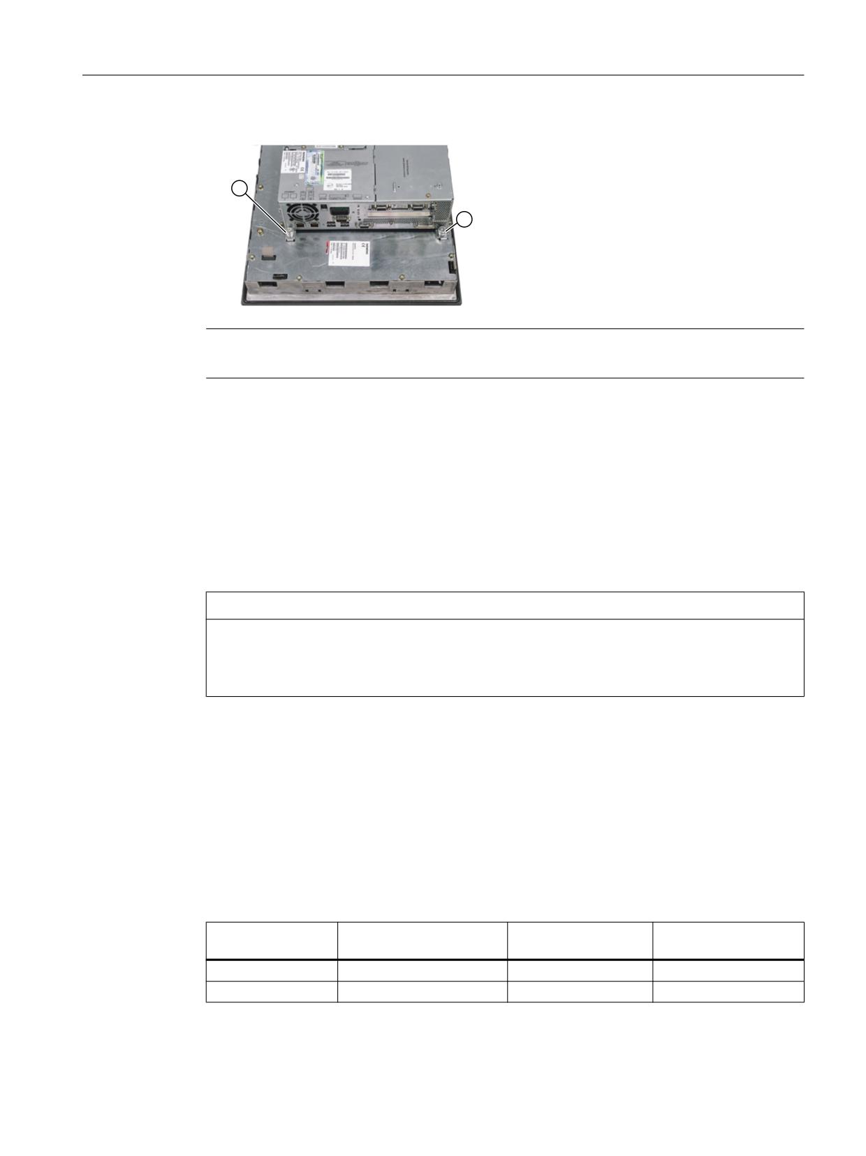
7. Secure the PCU using two knurled screws
① at each end of the two mounting angles
(torque: 1.8 Nm).
Note
The OP 010 and TCU assembly is similar to that for a PCU.
7.4.3
Mounting on the mounting wall
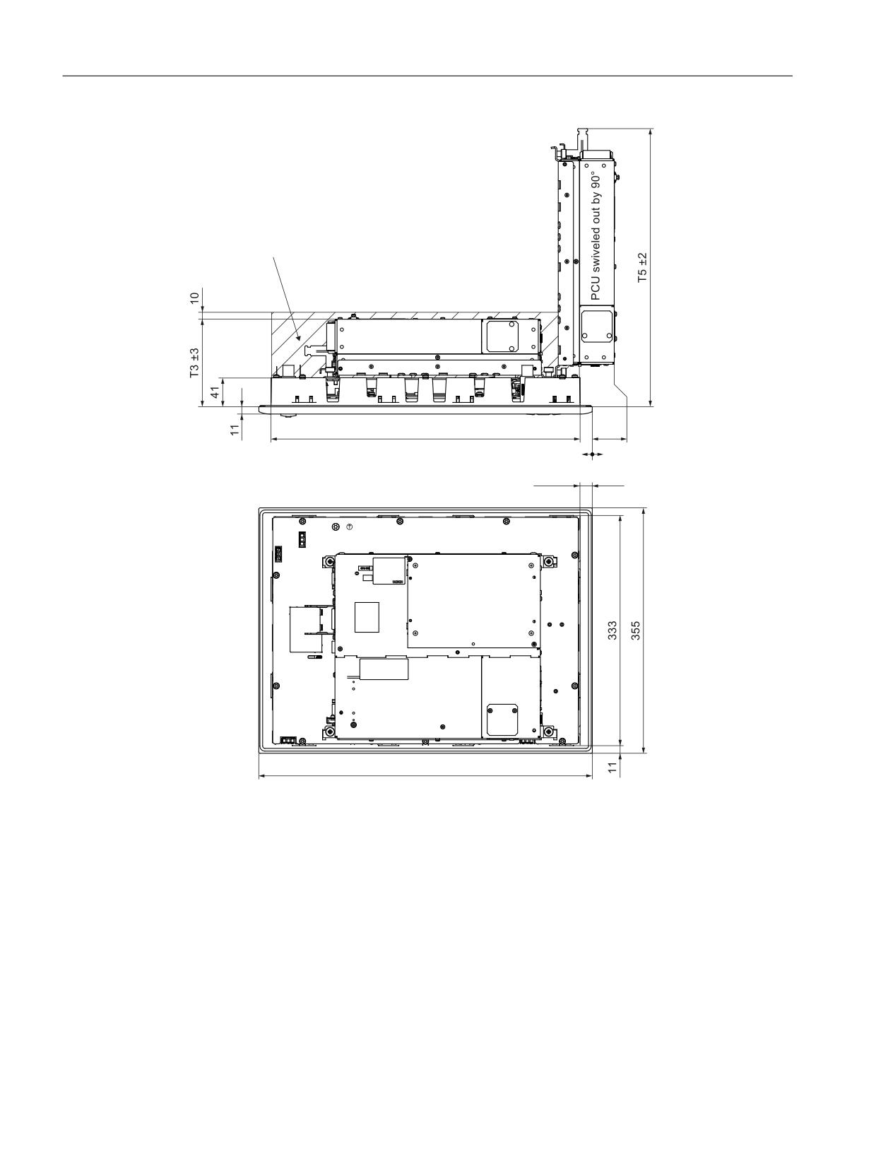
The clearance at the rear of the PCU/TCU must be at least 10 mm to ensure sufficient
ventilation.
For more detailed information, please refer to the relevant PCU sections and in "General
information and networking", Section: "Application planning", Section: "Climatic and
mechanical environmental conditions" → "Cooling".
NOTICE
Impermissible mounting positions can cause malfunctions
Observe the permissible mounting position: Deviating by up to 5º from the vertical.
This value can be further restricted by mounted components (e.g. PCU).
Procedure
1. Insert the assembled components (operator panel front and PCU) from the front into the
panel cutout (see Image 7-3 Dimension sheet for installing the OP 015A operator panel
front (Page 96)).
2. Secure the operator panel front in the panel cutout from the rear using the twelve tension
jacks by tightening the setscrews (torque 0.5 Nm).
Table 7-2
Dimensions to be observed when installing
Mounting depth T3 + clear-
Opening depth T5
Protrusion P
ance (mm)
(mm)
(mm)
PCU 50.5
127 + 10
402
32
TCU x0.2
76 + 10
376
-19
Operator panels
Manual, 03/2016, 6FC5397-1AP40-5BA3
99
Operator panel front: OP 015A
7.4 Mounting
&OHDUDQFH IRU FDEOHV DQG YHQWLODWLRQ
3&8 LQ WKH HQG SRVLWLRQ
s
s
s
Image 7-5
Attaching the PCU to the OP015A operator panel front
7.4.4
Softkey labeling
User-specific functions can be assigned to the two vertical softkey bars. Printed labeling strips
can be used to label the softkeys.
Blank labels are already factory-installed.
Operator panels
100
Manual, 03/2016, 6FC5397-1AP40-5BA3
Operator panel front: OP 015A
7.5 Technical specifications
DIN A4 films are available for preparing the vertical strips. You can find the article number in
Section "Spare parts" → "Overview".
Note
Use the "Arial" font to format text. This font is comparable to the "Univers S57" font, used by
Siemens for the key labeling.
Procedure
1. Label the mat side of the film with a laser printer or another printer that allows "Film" to be
set as a printable medium.
2. Cut the printed labels along the preprinted lines.
3. Insert the labeling strips into the slits provided from the rear of the operator panel front (refer
to figure: "OP 015A housing open" in section: "Spare parts" → "Replacement".
Note
In order to facilitate insertion of the "Teil 1" strip when the PCU is mounted, it is
recommended that you
- unscrew the four retaining screws of the PCU and
- swing the PCU up.
Once you have inserted the strip, swing the PCU back to the operator panel and secure by
tightening the screws.
7.5
Technical specifications
Safety
Safety class
III; PELV according to EN 50178
Degree of protection accord-
Front side: IP65
ing to EN 60529
Rear side: IP00
Approvals
CE / cULus
Electrical data
Power supply
Display
Backlight inverter
Logic / USB
(via K1 and K2)
Voltage
4.9 V - 5.25 V
12 V +/- 5%
5.0 V - 5.2 V
Current (typ./max.)
approx. 420/700 mA
approx. 900/1100 mA
approx. 350/1050 mA
Power consumption
Typical, approx. 15 W
Maximum approx. 25 W
Mechanical data
Dimensions
Width: 483 mm
Height: 355 mm
Depth: 53 mm
Weight
Approx. 8.4 kg
Max. tightening torques:
Tension jack screws:
M3 screws:
M4 screws:
0.5 Nm
0.8 Nm
1.8 Nm
Operator panels
Manual, 03/2016, 6FC5397-1AP40-5BA3
101
Operator panel front: OP 015A
7.6 Spare parts
Display
Size / resolution
15" TFT / 1024 x 768 pixels
MTBF backlight
typ. 50,000 h at 25º C (dependent on the temperature)
Note
Information about the climatic and mechanical environmental conditions is contained in the
associated section under:
"General notes and interconnection" → "Operational planning".
7.6
Spare parts
7.6.1
Overview
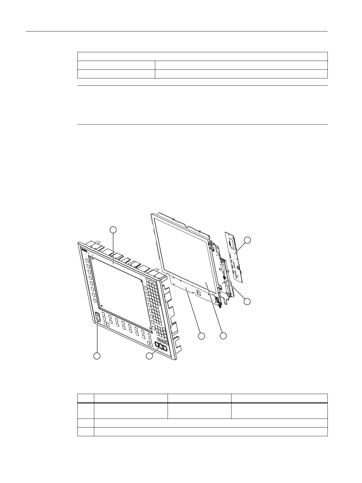
The diagram shows the OP 015A operator panel front dismantled into its individual parts.
Image 7-6
Individual parts for the OP 015A operator panel front
The components listed in the following table with an article number are available as spare parts.
Spare part
Article number
Remark
①
Operator panel front
A5E00405090
Without LCD unit, mouse, USB port
and keyboard controller
②
Keyboard controller
③
Background lighting with backlight inverter
Operator panels
102
Manual, 03/2016, 6FC5397-1AP40-5BA3
Operator panel front: OP 015A
7.6 Spare parts
Spare part
Article number
Remark
④
LCD unit
⑤
Display support
⑥
USB mouse
6FC5247-0AF01-0AA0
⑦
USB caps
6FC5248-0AF05-0AA0
Set of 10
Tension jacks
6FC5248-0AF14-0AA0
Set of 9
Slide-in strips that can be la-
6FC5248-0AF24-0AA0
Set with 3 foils, DIN A4
beled
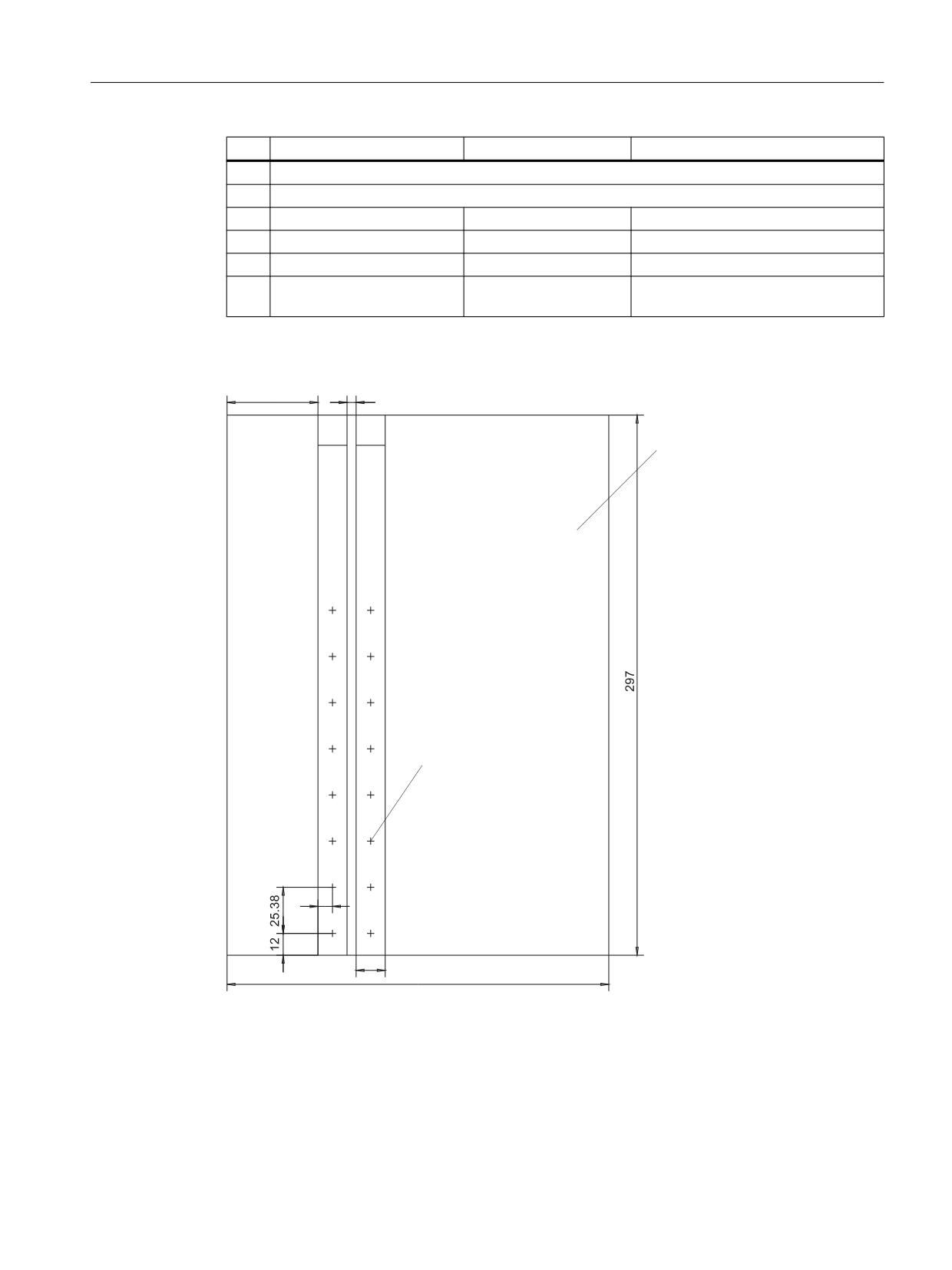
The dimensions for creating slide-in labels from the foil for labeling the vertical softkeys can
be seen in the following diagram.
3DUW
3DUW
)LOP ',1 $
&HQWHU RI WKH NH\
Image 7-7
Dimensions for slide-in labels
Operator panels
Manual, 03/2016, 6FC5397-1AP40-5BA3
103
Operator panel front: OP 015A
7.6 Spare parts
7.6.2
Replacement
NOTICE
Risk of damage to sensitive components due to static electricity
Spare parts must always be replaced by properly trained personnel!
USB cap / tension jack
The replacement of the USB sealing cap and tension jacks will not be described since it is
simple and self-explanatory.
Operator panel front
When the operator panel front is replaced, the display, keyboard controller, mouse, and USB
interface can be used again. They are therefore disassembled and reassembled after the
appropriate component has been replaced.
Note
We recommend reusing the keypad controller to prevent any loss of the control parameters
that have been programmed in.
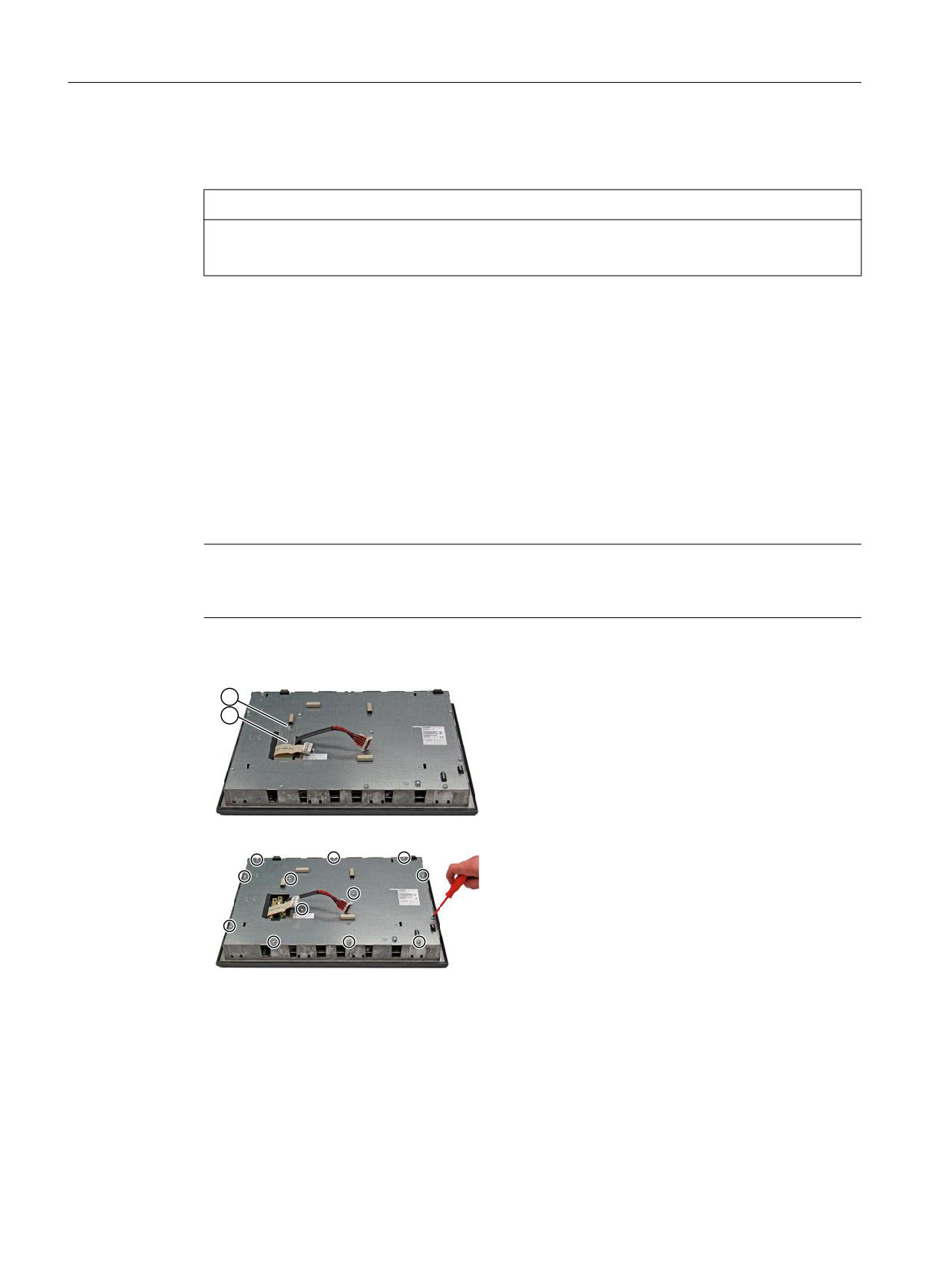
Dismounting individual parts from the operator panel front
1. Place the OP 015A on a soft, horizontal support.
Remove the retaining screw (M3) ① from the
cover plate ② and lift off the cover plate.
2. Release the 13 housing screws (M4).
3. Lift off the cover.
Operator panels
104
Manual, 03/2016, 6FC5397-1AP40-5BA3
Operator panel front: OP 015A
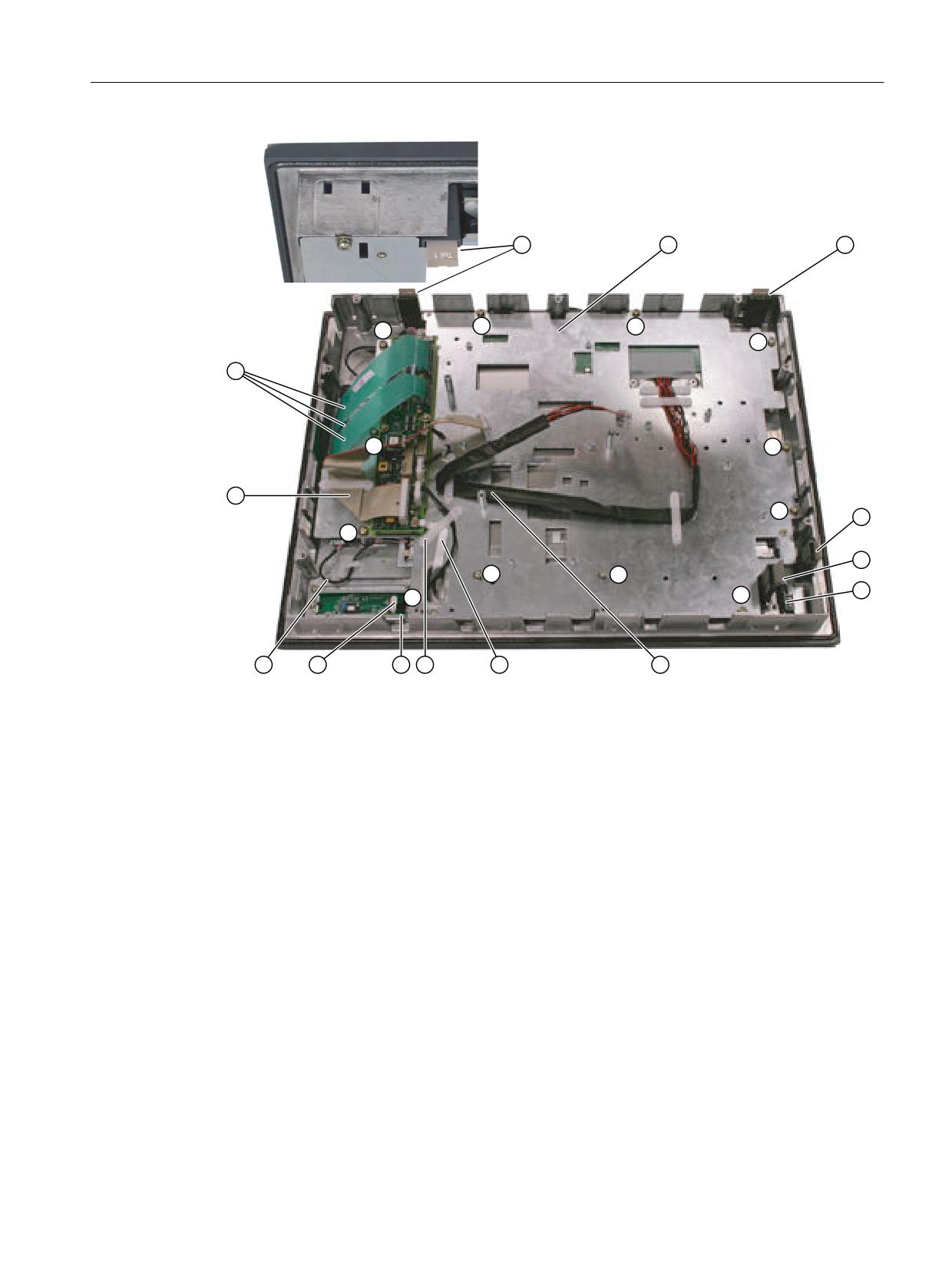
7.6 Spare parts
① Screws (M4) for display support
② Slide-in labels (Teil 1)
③ Display support
④ Slide-in labels (Teil 2)
⑤ Slide-in labels (Teil 3)
⑥ Slide-in labels (Teil 4)
⑦ USB interface
⑧ Display cable K2
⑨ Ribbon cable keyboard controller / USB connection
⑩ Retainer for the mouse / keyboard controller cable
⑪ Interface for the mouse
⑫ Cable plug for mouse / keyboard controller
⑬ Backlight inverter cable
⑭ I/O USB cable K1
⑮ Keyboard cable
Image 7-8
OP 015A housing open
Operator panels
Manual, 03/2016, 6FC5397-1AP40-5BA3
105
Operator panel front: OP 015A
7.6 Spare parts
Backlight inverter cable
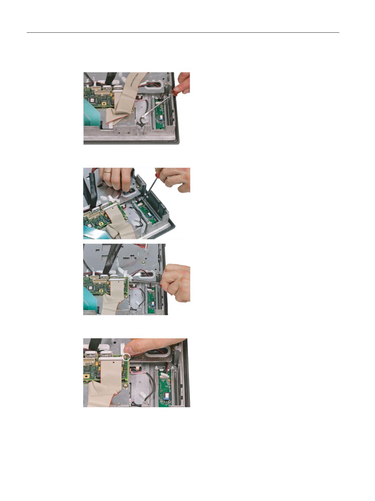
4. Remove the two cables to the backlight inverter
(to the left and right of the display support) by
raising the clips with a flat screwdriver and pull-
ing out the cables.
Connection of keyboard controller / mouse
5. Undo the connection between the keyboard
controller and the mouse by carefully pushing
the connector back with a screwdriver.
6. Remove the retainer for the cable between the
keyboard controller and mouse.
Connection of keyboard controller / USB interface
7. Disconnect the connection from the USB inter-
face to the keyboard controller by pulling back
the terminal clamps to the left and right of the
plug.
Operator panels
106
Manual, 03/2016, 6FC5397-1AP40-5BA3
Operator panel front: OP 015A
7.6 Spare parts
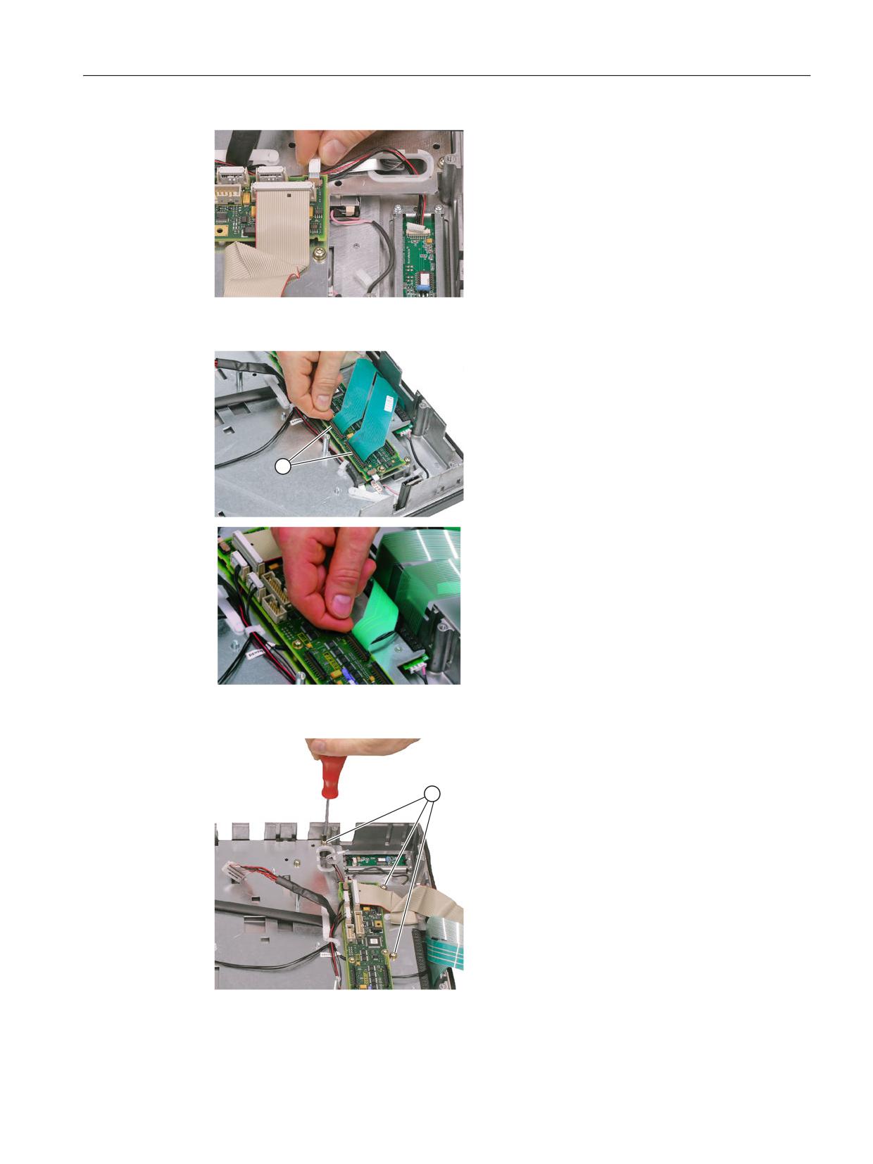
8. Remove the plug of the USB cable from the
keyboard controller.
Keyboard cables
9. Disconnect the 3 keyboard cables by pushing
up the terminal holders ① on the keyboard
controller and pulling the keyboard cables out
of the holder.
For detailed information about removal and in-
sertion of membrane connectors, see also
"General information and networking", Section:
"Connecting", Section: "Handling membrane
connectors".
Display supports
10. Remove the twelve screws ① from the display
support.
For the arrangement of the screws on the dis-
play support, refer to Figure: "OP 015A housing
open".
Operator panels
Manual, 03/2016, 6FC5397-1AP40-5BA3
107
Operator panel front: OP 015A
7.6 Spare parts
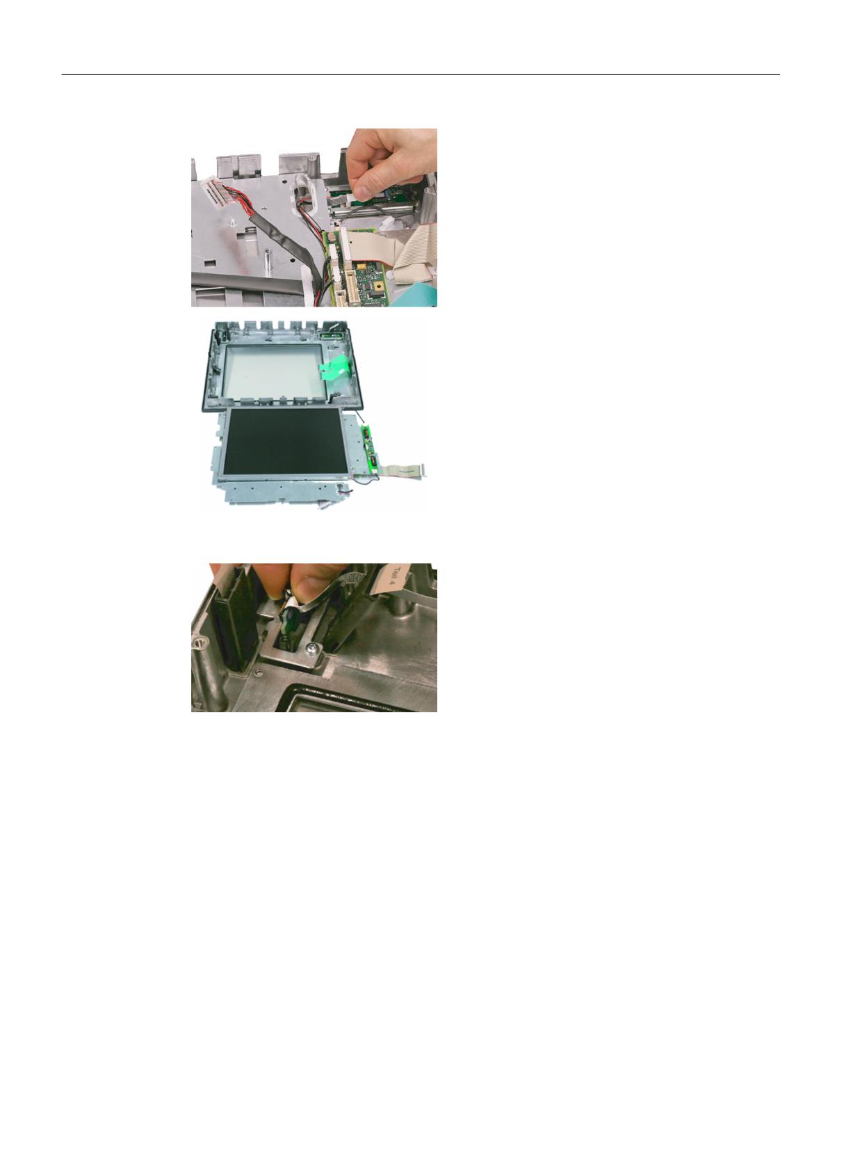
11. Insert the USB ribbon cable in the direction of
the arrow through the opening and pull it out.
12. Lift off the display support.
13. Lay the display support down on its back to
avoid damaging the display.
USB board
14. Remove the USB interface by sliding up both
retaining clamps and pulling out the board.
Mouse board
Operator panels
108
Manual, 03/2016, 6FC5397-1AP40-5BA3
Operator panel front: OP 015A
7.6 Spare parts
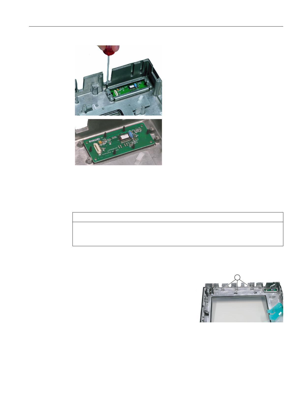
15. Loosen the four screws (M3) on the holder for
the mouse board. Lift off the holder and the
mouse board.
Installing the individual parts in the operator panel front
1. Remove the transportation safety precautions (adhesive strip for securing cables) and the
screen protective sheeting from the inside.
2. Install the components in the new operator panel front in the order indicated:
NOTICE
Damage to the screws
Pay attention to the torques when tightening the screws (see Technical specifications
(Page 101)).
15.
Mouse board and bracket
14.
USB board
Press the USB board into place until you
hear it lock into the retaining clamps.
Check the secured position of the USB cable
behind the guide pins ①.
13. - 10. Display support
Operator panels
Manual, 03/2016, 6FC5397-1AP40-5BA3
109
Operator panel front: OP 015A
7.6 Spare parts
13.
Bend the keyboard cables
① back
slightly before inserting the display
support
to prevent pinching and damage,
which could render them inoperable.
11.
Insert the USB ribbon cable in the op-
posite direction of the arrow through
the opening and pull it out.
9.
Keyboard cables
8. - 7.
Connection of keyboard controller / USB interface
8.
Ensure that the contact side ① of the
USB plug faces upwards.
6. - 5.
Connection of keyboard controller / mouse
4.
Backlight inverter cable
3. - 1.
Cover
Operator panels
110
Manual, 03/2016, 6FC5397-1AP40-5BA3
Operator panel front: OP 015AT
8
8.1
Description
The SINUMERIK OP 015AT operator panel front with 15" TFT color display
and 1024 x 768 pixels (XGA) enables the spatially distributed installation of the operator panel
front and the control. It features a membrane keyboard with 62 keys and 2 x (8 + 2) horizontal
and 2 x 8 vertical softkeys and an integrated mouse.
The OP 015AT operator panel front is linked to the PCU/NCU via Ethernet as thin client in a
dedicated subnet (via DHCP server on the PCU/NCU). The distance to the operator panel
fronts is determined by the maximum distance between two network nodes / access points
(100 m). Mixed operation with several TCUs and one operator panel front directly on the PCU
is possible.
The operator panel front is secured from the rear using special clamps supplied with the panel.
Validity
This description applies to:
Type
Description
Article number
OP 015AT
As a thin client, operator panel front with membrane key-
6FC5203-0AF05-1AB1
board
Features
● Ethernet 10/100/1000 Mbit/s
●
4 x USB (3 x rear, 1 x front)
●
15" TFT flat screen (color) with resolution 1024 x 768 pixels
● Membrane keyboard with alphabetic, numeric, cursor, and control keypad
● Softkeys / direct keys:
-
2 x (8 + 2) horizontal rows of keys with softkey function
–
2 x 8 vertical rows of keys with softkey and direct key functions
● Shift key for switchover to the second key level (not for switching over the letters, since
they are uppercase only)
● Integrated mouse
● Status LEDs for power supply and overtemperature
● Panel cutout (W x H): 450 x 335 mm
● Degree of protection IP65 (front)
● Attachment: Tension jacks at the rear
Operator panels
Manual, 03/2016, 6FC5397-1AP40-5BA3
111