SINUMERIK 840D sl Hardware. Manual (2011-2020) - page 5
Operator panel front: OP 019
12.1 Description
● Attachment: Tension jacks at the rear
The tension jacks can be re-ordered as spare part: 6FC5248-0AF14-0AA0 (9 units)
● Can be combined with PCU 50.5 and TCU 30.2
Note
Connecting USB devices
OP 019 has no USB interfaces. If required, the USB interfaces of the PCU 50.5 / TCU 30.2
can be routed to the front via a USB-extension (see Chapter: "Keyboards and additional
components").
Operator panels
178
Manual, 03/2016, 6FC5397-1AP40-5BA3
Operator panel front: OP 019
12.2 Operator control and display elements
12.2
Operator control and display elements
12.2.1
View
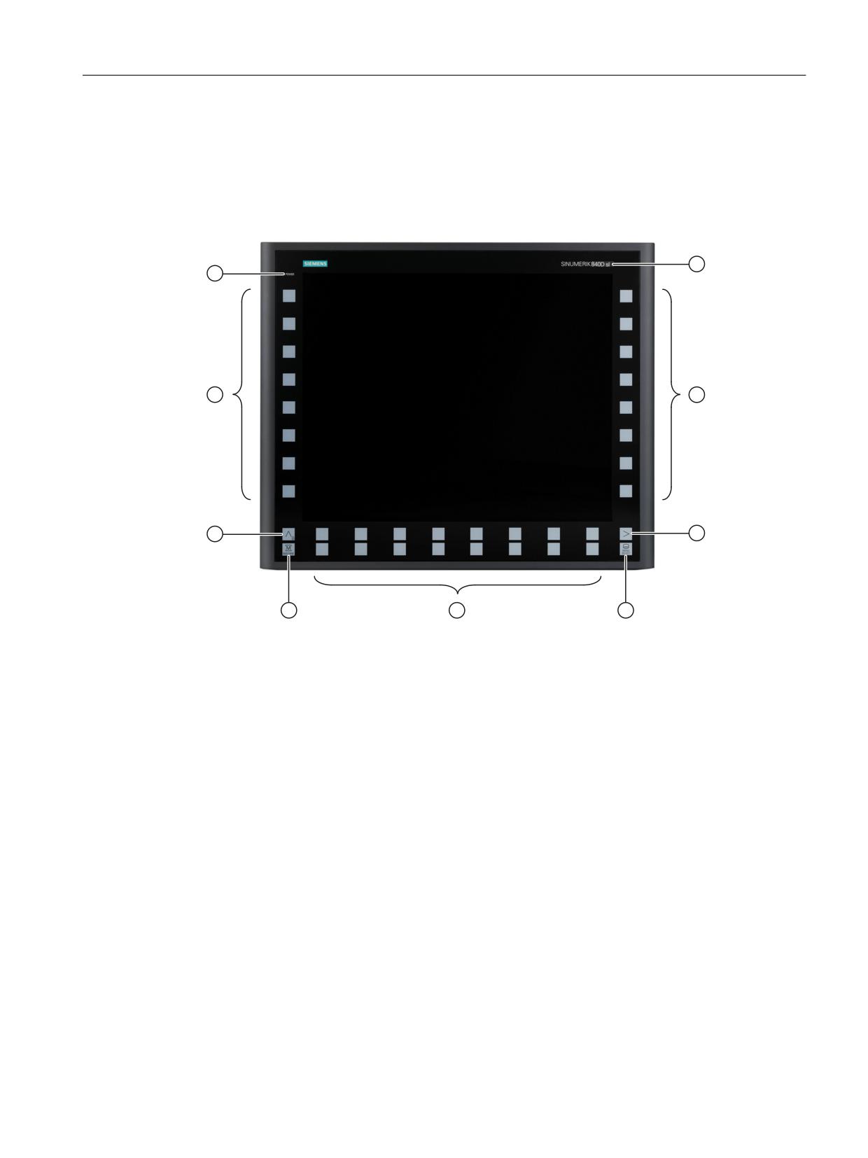
① Status LED: POWER
② Window for slide-in labels "System" (e.g. 840D sl)
③ Vertical softkeys
④ Menu forward key
⑤ Menu select key
⑥ Horizontal softkeys
⑦ Machine area key
⑧ Menu back key and key disable
Image 12-1 Front view of the OP 019 operator panel front
Operator panels
Manual, 03/2016, 6FC5397-1AP40-5BA3
179
Operator panel front: OP 019
12.2 Operator control and display elements
12.2.2
Keyboard
Keyboard
The following keys are arranged on the operator panel front:
● The 16 vertical and horizontal softkeys call up functions that are available on screen via a
menu bar.
● The menu back key switches to the higher-level horizontal menu back and is used to lock
the keys.
● The menu forward key advances in the extended horizontal softkey bar.
● The Menu Select key calls the main menu to select the operating area.
● The machine area key selects the "Machine" operating area.
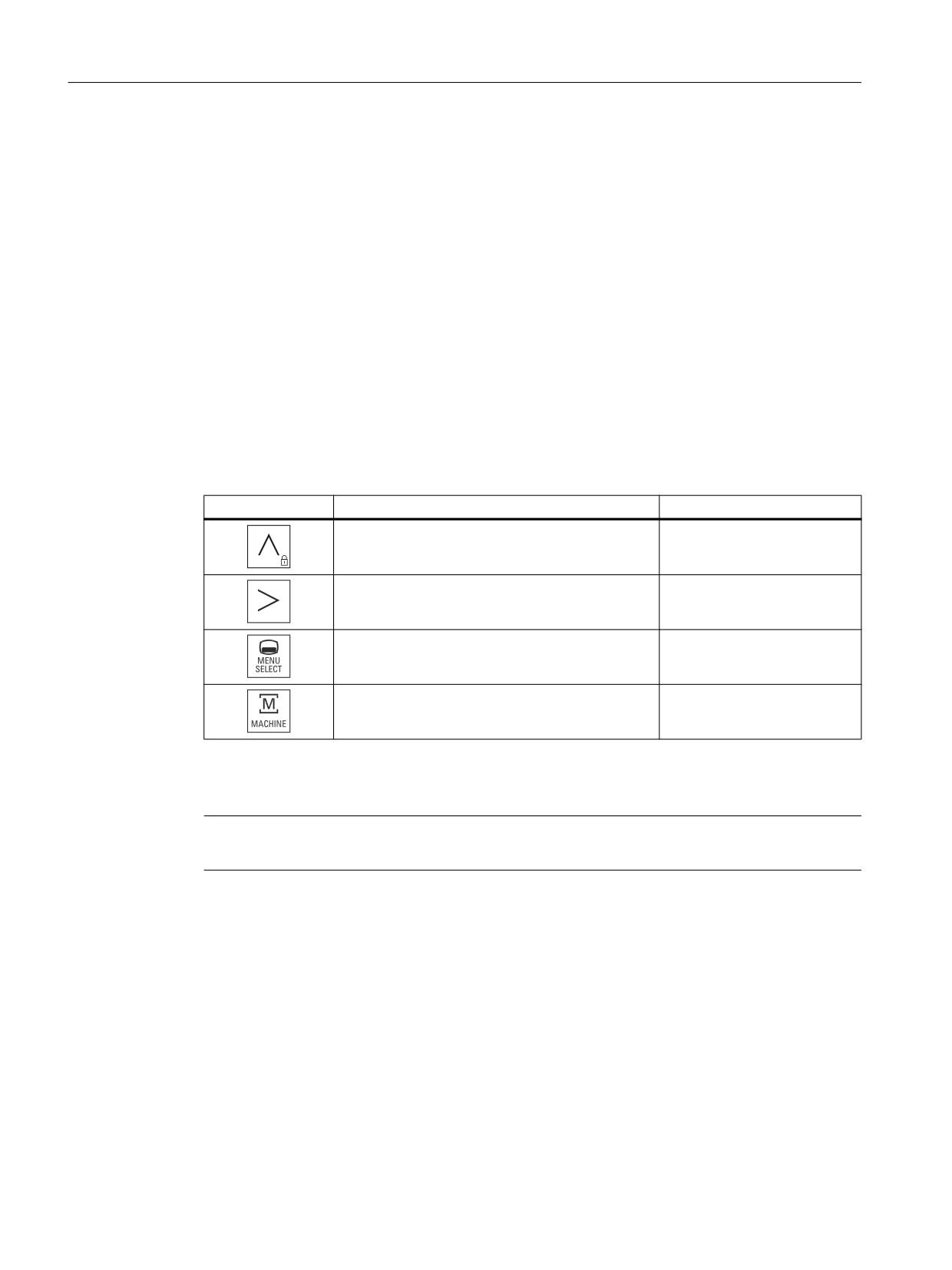
The key symbols used on the operator panel front are juxtapositioned with the corresponding
function keys on the PC keyboard.
Key
Description
PC function key
Menu back key / keyboard lock
F9
Menu forward key
<Shift> F9
Menu select key
F10
Machine area key
<Shift> F10
Display
Note
Pixel error acc. to DIN EN ISO 13406-2 Class II.
Operator panels
180
Manual, 03/2016, 6FC5397-1AP40-5BA3
Operator panel front: OP 019
12.2 Operator control and display elements
12.2.3
Softkeys
Operation
The capacitive keys respond quickly and directly. In order to prevent accidental operation, the
following measures must be applied:
● When the key is pressed a second time, the function is revoked
● Keyboard lock, e.g. when cleaning the keys/keyboard:
- Press the menu back key for longer than 5 seconds to activate it
- The associated LED flashes while the key lock is active
- Deactivate the keyboard lock by pressing again (> 5 s)
● Traversing motion that is initiated using direct keys must be additionally interlocked: For
example, using an acknowledgment button that is appropriately linked in the PLC
Note
Please observe the valid C standards for the particular machine type (e.g. for lathes: EN
ISO 23125-2010, pages 36+49). This states that a button that initiates motion with the
protective door open must be implemented using an additional acknowledgment device;
this is because for single-channel keyboards - such as the OP 019 - generally no PL
(performance level) level "d" can be achieved.
Special situations:
●
2 keys can be simultaneously pressed.
● The keys can also be actuated when operators are wearing gloves. However, especially
thick, protective gloves can restrict operation or even prohibit it.
LED displays
All keys with LEDs flash green:
● As long as the operating system has not started while booting.
● If communication to the PCU/TCU has failed and this state lasts for more than 5 s.
Remedy: Re-install the standard keyboard driver.
12.2.4
Screen saver
If a screen with high contrast is displayed unchanged for longer than an hour, then the
screensaver must be activated in order to protect the TFT display against so-called "burning
in" of the last displayed screen.
The time can be adapted individually. Further information can be found at:
Commissioning of Basic Software and Operating Software, SINUMERIK Operate (IM9)
Operator panels
Manual, 03/2016, 6FC5397-1AP40-5BA3
181
Operator panel front: OP 019
12.3 Interfaces
12.3
Interfaces
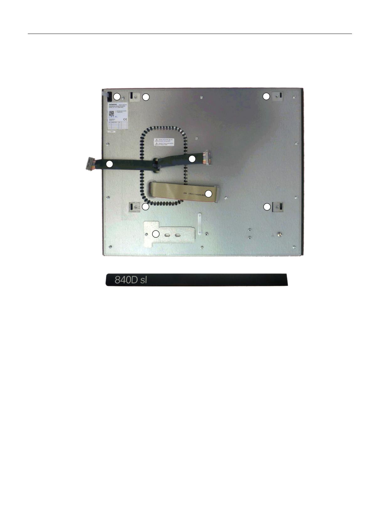
All interfaces of the OP 019 operator panel front are located at the rear:
① Insertion slot for the "System" labeling strips
② Mounting slots for PCU/TCU lugs
③ Cover plate for the direct key interface X11
④ I/O USB cable K1
⑤ LVDS display cable K2
⑥ LVDS display cable K3
Image 12-2 Rear of the OP 019
Operator panels
182
Manual, 03/2016, 6FC5397-1AP40-5BA3
Operator panel front: OP 019
12.3 Interfaces
Interface description
● Three flat ribbon cables for connecting the PCU/TCU:
- I/O USB cable K1:
all signals, which in addition to the display interface, are required to connect operator
panel fronts (e.g. supply voltages)
- LVDS display cable K2
- LVDS display cable K3
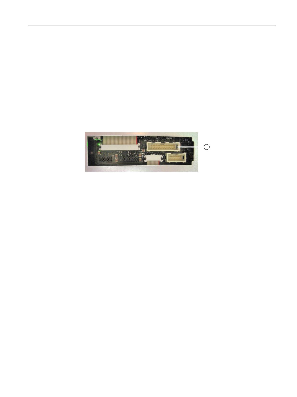
● Direct key interface X11 ① for the two vertical softkey bars (16 keys).
Here, one of the following operator components can be connected:
- MCP 483 / MCP 483 PN / MPP 483 / MPP 483 IE (X70)
- TCU 30.2 (X205)
Pin assignment
The pin assignment of the interfaces, see "General information and networking" →
"Connecting".
Operator panels
Manual, 03/2016, 6FC5397-1AP40-5BA3
183
Operator panel front: OP 019
12.4 Mounting
12.4
Mounting
12.4.1
Preparation for mounting
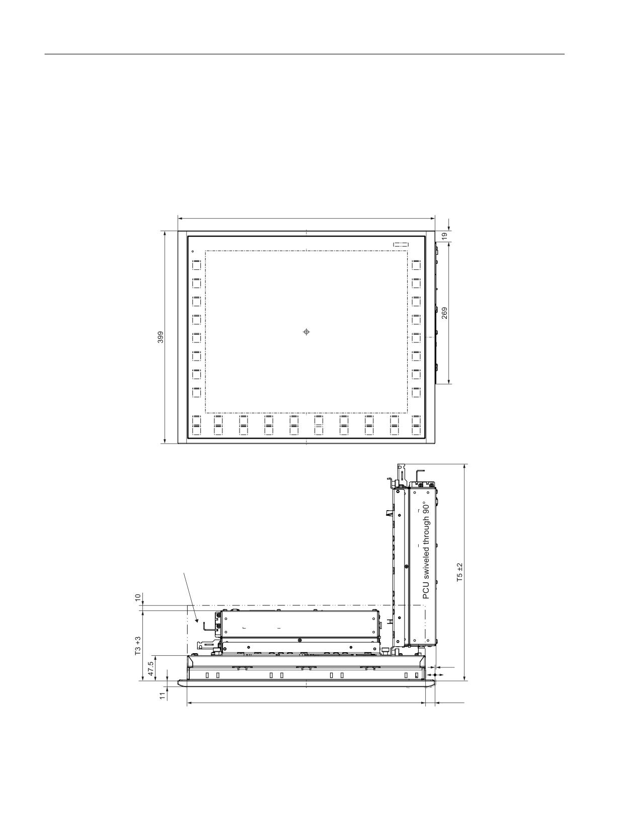
Overview
6SDFH IRU FDEOHV DQG YHQWLODWLRQ
3&8 LQ ILQDO SRVLWLRQ
s
s
Image 12-3 Dimension sheet for attaching the PCU to the OP 019 operator panel front
Operator panels
184
Manual, 03/2016, 6FC5397-1AP40-5BA3
Operator panel front: OP 019
12.4 Mounting
Table 12-1
Dimensions to be observed when installing
Mounting depth T3 + clear-
Opening depth T5
Protrusion P
ance (mm)
(mm)
(mm)
PCU 50.5
132 + 10
408
2
TCU 30.2
81 + 10
382
-49
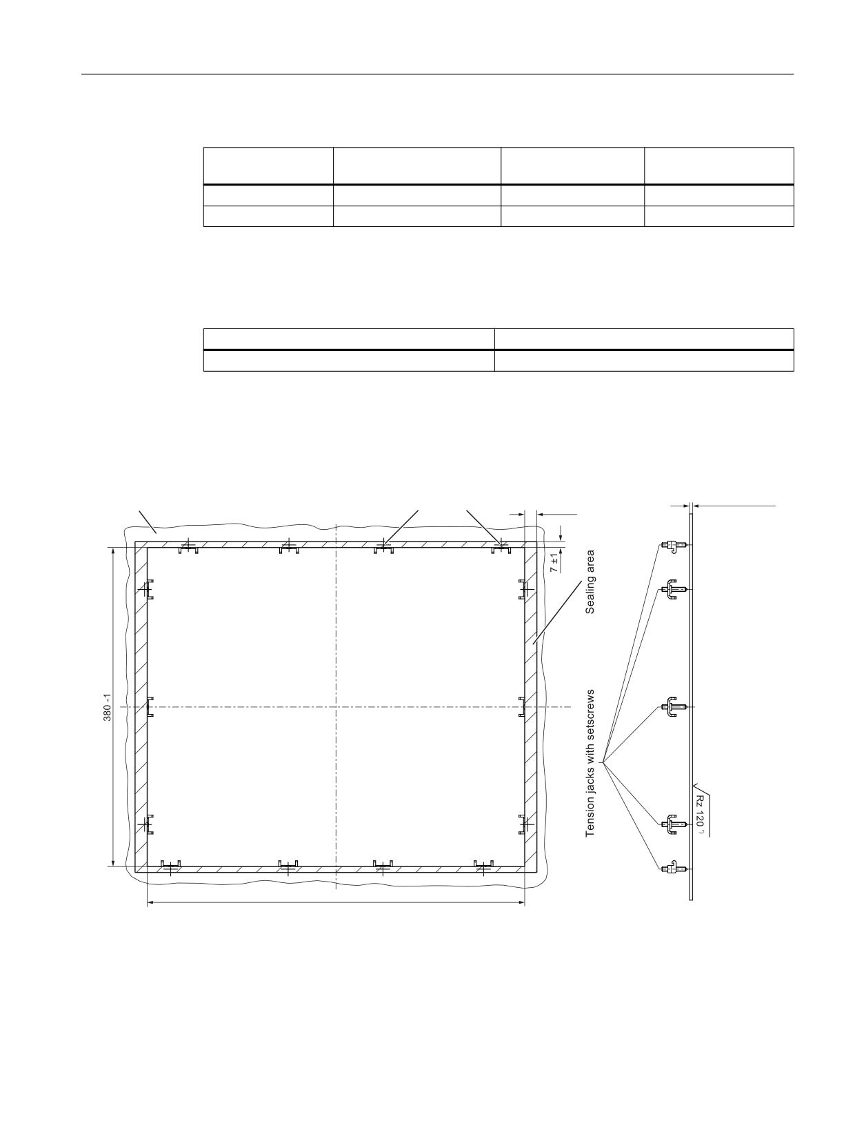
Mounting opening
Table 12-2
Dimensions of the mounting opening
Width (mm)
Height (mm)
450
380
The OP 019 is mounted using the tension jacks provided (2.5 mm profile; 20 mm long). When
using the tension jacks, holes or threaded holes are not required.
This mounting method also enables the IP65/IP66 degree of protection if the mounting panel
corresponds to the requirements specified in the dimension drawing. The seal (PU foam seal)
to the mounting panel is already provided on the OP 019.
IRU ,3
0RXQWLQJ SDQHO
3UHVVXUH SRLQWV IRU WHQVLRQ MDFNV
s
IRU ,3
,Q WKH VHDOLQJ DUHD
Image 12-4 Dimension drawing for installing the OP 019 operator panel front
Operator panels
Manual, 03/2016, 6FC5397-1AP40-5BA3
185
Operator panel front: OP 019
12.4 Mounting
Precondition for the assembly with a PCU/TCU
Before you mount a PCU/TCU onto an OP 019, you must attach the mounting brackets on the
PCU/TCU.
The mounting brackets for a TCU 30.2 are attached the same way as for a PCU.
Exception: When attaching, only 4x M4x8 fillister head screws are required.
12.4.2
Assembling an OP 019 and a PCU
If you wish to combine the OP 019 with a PCU, assemble the components before installing
them into the mounting panel. This procedure is described in detail below. Alternatively, you
can first install the OP 019 in the panel cutout and then mount the PCU on the installed OP.
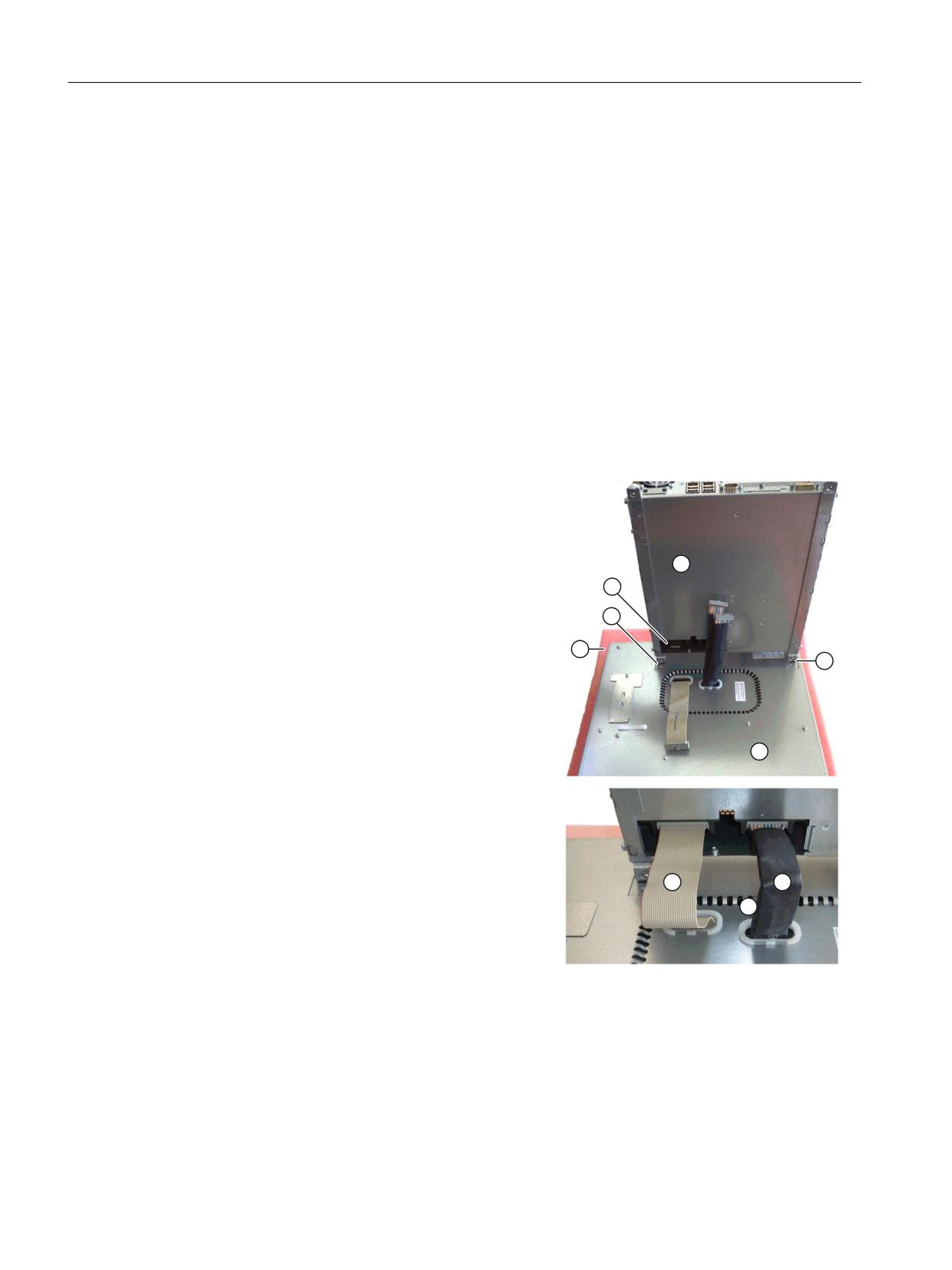
Procedure
1.
Place the front of the OP 019 ① on a soft,
horizontal surface ② to avoid damaging
the surface of the operator panel front.
2.
Remove the interface cover ④ of the PCU
⑤.
3.
Position the PCU so that the mounting lugs
③ engage in the OP 019.
4.
Connect cables K1 ① and K2 ② to the
interfaces of the PCU. K3 ③ is first routed
through the opening behind K2.
5.
Ensure that the connectors of cables K1
and K2 snap audibly into place and that the
interlocks are closed.
Operator panels
186
Manual, 03/2016, 6FC5397-1AP40-5BA3
Operator panel front: OP 019
12.4 Mounting
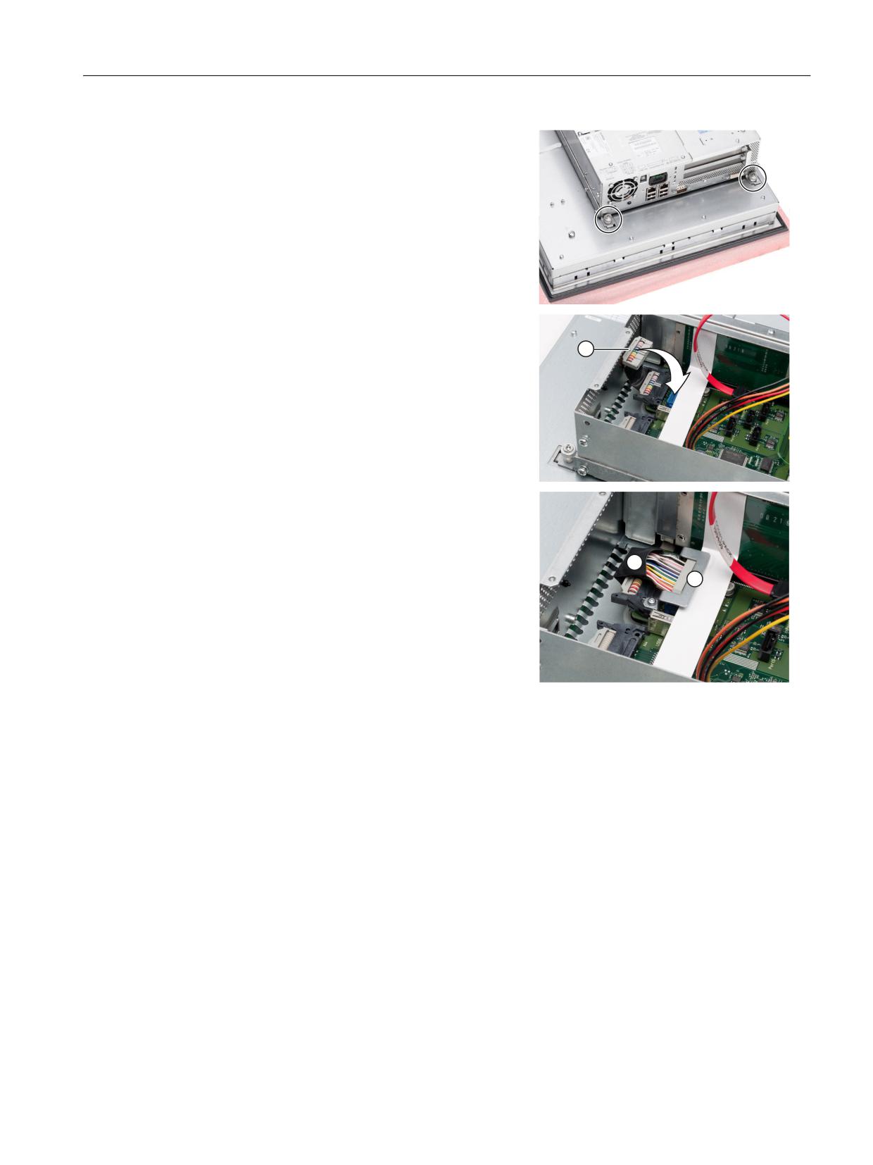
6.
Swivel the PCU in the direction of the OP
019 and make sure that the cables fold
correctly into place.
7.
Secure the PCU using two knurled screws
at each end of the two mounting angles
(torque: 1.8 Nm).
8.
In order to insert cable K3 ①, you must
remove the housing cover of the PCU hard
disk, seeSSD module (Page 266) Chapter
PCU 50.5.
9.
Connect cable K3 ① to the interface of the
PCU, directly above K2, and secure the
connector using the fixing bracket ② and
two M2.5 screws (0.4 Nm).
10. Close the housing cover of the PCU (see 8.).
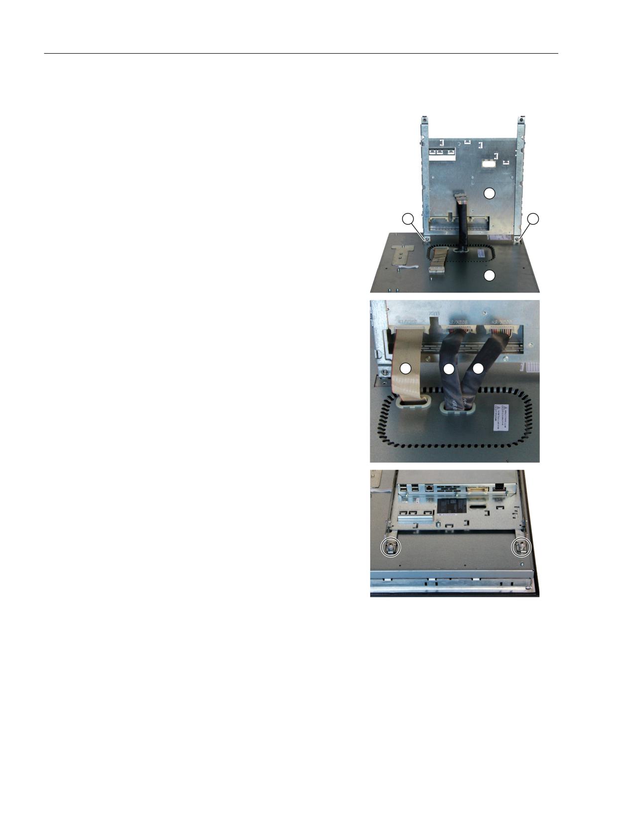
12.4.3
Assembling an OP 019 and a TCU
If you wish to combine the OP 019 with a TCU, assemble the components before installing
them into the mounting panel. This procedure is described in detail below. Alternatively, you
can first install the OP 019 in the panel cutout and then mount the TCU on the installed OP.
Operator panels
Manual, 03/2016, 6FC5397-1AP40-5BA3
187
Operator panel front: OP 019
12.4 Mounting
Procedure
1.
Place the front of the OP 019 ③ on a soft,
horizontal surface to avoid damaging the
surface of the operator panel front.
2.
Position the TCU ② so that the mounting
lugs ① engage in the OP 019 ③.
3.
Connect cables K1 ①, K2 ② and K3 ③
to the appropriate interfaces of the TCU.
4.
Ensure that the connectors of cables K1 to
K3 snap audibly into place and that the in-
terlocks are closed.
5.
Swivel the TCU in the direction of the OP
019 and make sure that the cables fold
correctly into place.
6.
Secure the TCU using two knurled screws
at each end of the two mounting angles
(torque: 1.8 Nm).
12.4.4
Mounting on the mounting wall
The clearance at the rear of the PCU/TCU must be at least 10 mm to ensure sufficient
ventilation (see Section: Preparation for mounting (Page 184)).
Operator panels
188
Manual, 03/2016, 6FC5397-1AP40-5BA3
Operator panel front: OP 019
12.5 Technical data
You should also observe the data provided in Section "General information and networking"
→ "Application planning" → "Climatic and mechanical environmental conditions" → "Cooling".
NOTICE
Impermissible mounting positions can cause malfunctions
Observe the permissible mounting position: Deviating by up to 5º from the vertical.
This value can be further restricted by mounted components (e.g. PCU).
Procedure
NOTICE
Damage to the glass front
Do not use suction grippers to lift the glass fronts in order to avoid damaging it.
1. Install the assembled components (e.g. operator panel front and PCU) from the front into
the panel cutout (see Image 12-4 Dimension drawing for installing the OP 019 operator
panel front (Page 185)).
NOTICE
Damage to the sealing
It is not permissible that the seal is damaged when installing the device so that the
maximum achievable degree of protection can be fulfilled. Therefore, locate the
assembled components, centered in the middle of the panel cutout.
2. Secure the operator panel front in the panel cutout from the rear using the six tension jacks
by tightening the setscrews (torque 0.4 - 0.5 Nm).
12.5
Technical data
Safety
Safety class
III; PELV according to EN 50178
Degree of protection accord-
Front, IP65 / IP66
ing to EN 60529
Rear, IP20
Approvals
CE / cULus
Electrical and mechanical data
Power consumption
Typical, approx. 35 W
Maximum approx. 45 W
Dimensions
Width: 483 mm
Height: 399 mm
Depth: 58,5 mm
Weight
approx. 11 kg
Tightening torques
Tension jacks:
M3 screws:
M4 screws:
screws, max.
0.5 Nm
0.8 Nm
1.8 Nm
Operator panels
Manual, 03/2016, 6FC5397-1AP40-5BA3
189

Operator panel front: OP 019
12.5 Technical data
Display
Size / resolution
19" TFT / 1280 x 1024 pixels
MTBF backlight
typ. 50,000 h at 25º C (dependent on the temperature)
Note
Information about the climatic and mechanical environmental conditions is contained in the
associated section under:
"General notes and interconnection" → "Operational planning".
Operator panels
190
Manual, 03/2016, 6FC5397-1AP40-5BA3
Operator panel front: OP 019 black
13
13.1
Description
The SINUMERIK OP 019 black operator panel front has a touch-sensitive glass user interface
with multiple finger operator control. The integrated TCU enables the operator panel front and
control to be installed separately.
The OP 019 black operator panel front is coupled to the PCU/NCU via Ethernet as thin client
in a dedicated subnet (via DHCP server on the PCU/NCU). The distance to the operator panel
fronts is determined by the maximum distance between two network nodes/access points (100
m). Mixed operation with several TCUs and one operator panel front directly on the PCU is
possible.
The operator panel front is fastened from the rear with special clamping elements provided in
the scope of delivery.
Validity
This description applies to:
Type
Description
Article number
OP 019 black
Operator panel front as thin client with touch screen
6FC5303-0AF17-0AA0
Characteristics
●
18.5" LCD flat screen (color) in widescreen format
● Resolution: 1366 x 768px
● Aspect ratio 16:9
● LED backlight with integrated power supply
● Ethernet 10/100/1000 Mbit/s
●
3 x USB (max. high speed) on the rear
● Multiple finger operation in the screen area (gesture operation possible)
● Installation opening (W x H): 465 x 319 mm2
● Can be installed by one person (see Chapter "Installation")
● Degree of protection: IP65
● Attachment: Tension jacks at the rear
- Min./max. thickness of the wall 1.5 to 6 mm
Operator panels
Manual, 03/2016, 6FC5397-1AP40-5BA3
191
Operator panel front: OP 019 black
13.2 Operator control and display elements
Note
Connecting USB devices
The OP 019 black does not have any USB interfaces at the front. If required, the rear USB
interfaces can be routed to the front via a USB extension (see Section "Keyboards and
additional components" in the related Equipment Manual "Operator Components and
Networking").
13.2
Operator control and display elements
13.2.1
View
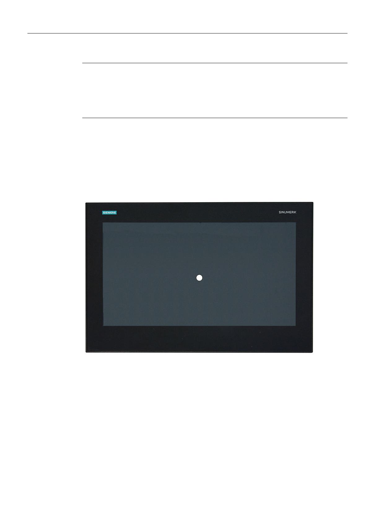
1
① Multiple finger operating area for operating software (softkeys) in the display area
Image 13-1 Front view of the OP 019 black operator panel front
Operator panels
192
Manual, 03/2016, 6FC5397-1AP40-5BA3
Operator panel front: OP 019 black
13.2 Operator control and display elements
13.2.2
Operation
The operator panel front is operated through finger contact with the touch-sensitive glass user
interface:
● Depending on the application-specific functions displayed in the display area, for example,
by:
- Gestures with up to 5 fingers
Note
Notes regarding operation of the touch-sensitive glass surface with multi-finger operation
function using gestures.
Observe the following notes in order to avoid incorrect operation of the touch-sensitive glass
surface with multi-finger operation function. Otherwise, entries made at the device will either
be incorrectly identified/implemented - or not at all.
● The OP 019 black does not support safety-relevant functions and these may also not be
implemented in the touch-sensitive glass user interface.
● The touch-sensitive glass user interface reacts to contact with its surface, not to pressure.
Therefore, do not subsequently attach a protective film to the touch-sensitive glass user
interface. Also remove all protection and packaging foils, as these have a negative impact/
prevent data from being entered and initiate incorrect operator entries.
● Only operate the touch-sensitive glass user interface with your finger tips, not with your
fingernails.
● Touch the touch-sensitive glass user interface either perpendicularly or at a maximum angle
of 45° to the surface.
● Avoid unintentional multiple touches, e.g. with the knuckles or by leaning on or against the
display.
● Make sure that the surface of the touch-sensitive glass screen does not get dirty. Cleaning
information can be found on the Internet in the following article in the Service & Support
portal of Siemens Industry:
Always check whether the executed operator actions were recognized by the device.
Note
Please observe the valid C standards for the particular machine type (e.g. for turning machines:
EN ISO 23125-2010, pages 36 and 49). These state that a button that initiates motion with the
protective door open must be implemented using an additional acknowledgment device; this
is because for single-channel keyboards - such as the OP 019 black - generally no PL
(performance level) "d" can be achieved.
Displaying the TCU menu
To display the TCU menu, simultaneously touch the left-hand and right-hand lower corner of
the active display area in order to display the TCU menu.
Operator panels
Manual, 03/2016, 6FC5397-1AP40-5BA3
193
Operator panel front: OP 019 black
13.2 Operator control and display elements
If you have connected a USB PC keyboard to the OP 019 black, then you can also display the
TCU menu by simultaneously pressing keys F9 and F10.
Gloves
Do not wear thick gloves, such as work gloves, when operating the touch-sensitive glass user
interface. You can wear thin gloves made of cotton or gloves for touch-sensitive glass user
interfaces with capacitive touch function.
You can wear the following gloves for operating the touch-sensitive glass user interface of the
operator panel:
● Dermatril L
● Camatril Velours Art. 730
● Uvex Profas Profi ENB 20A
● Comasec PU 900 (4342)
● Camapur Comfort Art. 619
● KCL Men at Work Art. 301
● Carex Art. 1505/k (leather)
● Cotton Cat. 1
Note
The gloves listed here are recommendations only. The type designations can change.
13.2.3
Screen saver
If an image with high contrast is displayed without change for longer than one hour, the dark-
ON function must be activated for energy efficiency reasons.
The time can be adapted individually. Further information can be found at:
Commissioning of Basic Software and Operating Software, SINUMERIK Operate (IM9)
Operator panels
194
Manual, 03/2016, 6FC5397-1AP40-5BA3
Operator panel front: OP 019 black
13.3 Interfaces
13.3
Interfaces
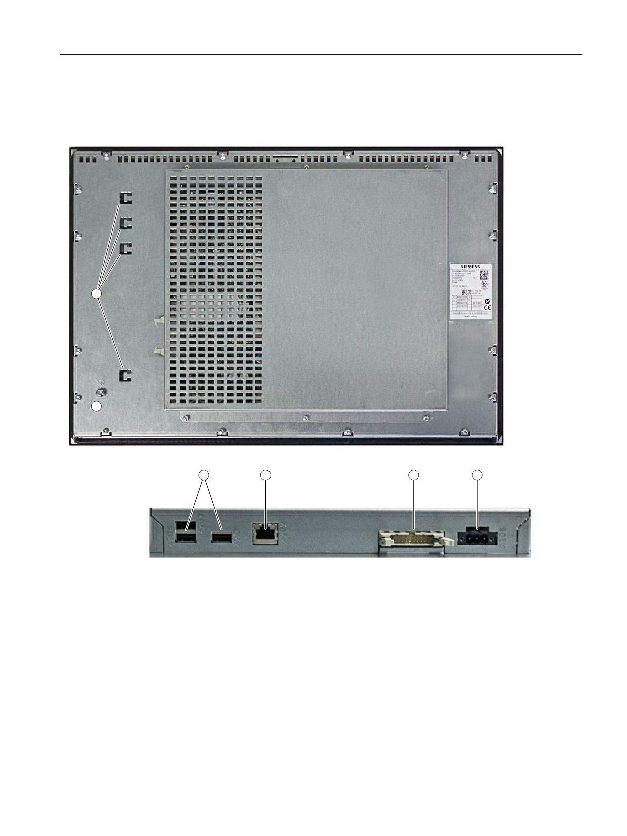
The OP 019 black operator panel front has the following interfaces:
1
2
3
4
5
6
①
-
Strain relief for connecting cables
②
-
M5 grounding screw (for screw connection with cable lug)
③
X203 / X 204 /
USB interfaces
X213
④
X202
Ethernet interface
⑤
-
Not relevant
⑥
X206
Power supply (with connector that can be screwed in place)
Image 13-2 OP 019 black - rear with interfaces
Operator panels
Manual, 03/2016, 6FC5397-1AP40-5BA3
195
Operator panel front: OP 019 black
13.3 Interfaces
NOTICE
Electrostatically endangered interface ⑤
Electronic modules contain components that are electrostatically endangered.
These modules can be easily destroyed if they are not handled properly.
To protect your equipment against damage, follow the instructions given below.
● Do not touch the open plug pins,
Interface name
Connector
Velocity
Permissible to-
Connector type
designation
tal length
Ethernet interface
X202
1000 Mbit/s
max. 100 m
8-pin RJ45 socket
Double USB interface 1
X203, X204
480 Mbps each
Max. 1.8 m
Double USB socket
24 V power supply
X206
-
max. 10m
3-pin Combicon con-
nector
USB interface 2
X213
480 Mbit/s
Max. 1.8 m
Single USB socket
Note
Restricted use of the USB interfaces
Please note that the USB interfaces installed in the OP 019 black cannot be used with every
USB-capable device. You can only connect keyboard, mouse and USB storage devices to the
019 black via the USB interfaces.
Pin assignment
The pin assignment of the interfaces, see "General information and networking" →
"Connecting".
Operator panels
196
Manual, 03/2016, 6FC5397-1AP40-5BA3
Operator panel front: OP 019 black
13.4 Installation
13.4
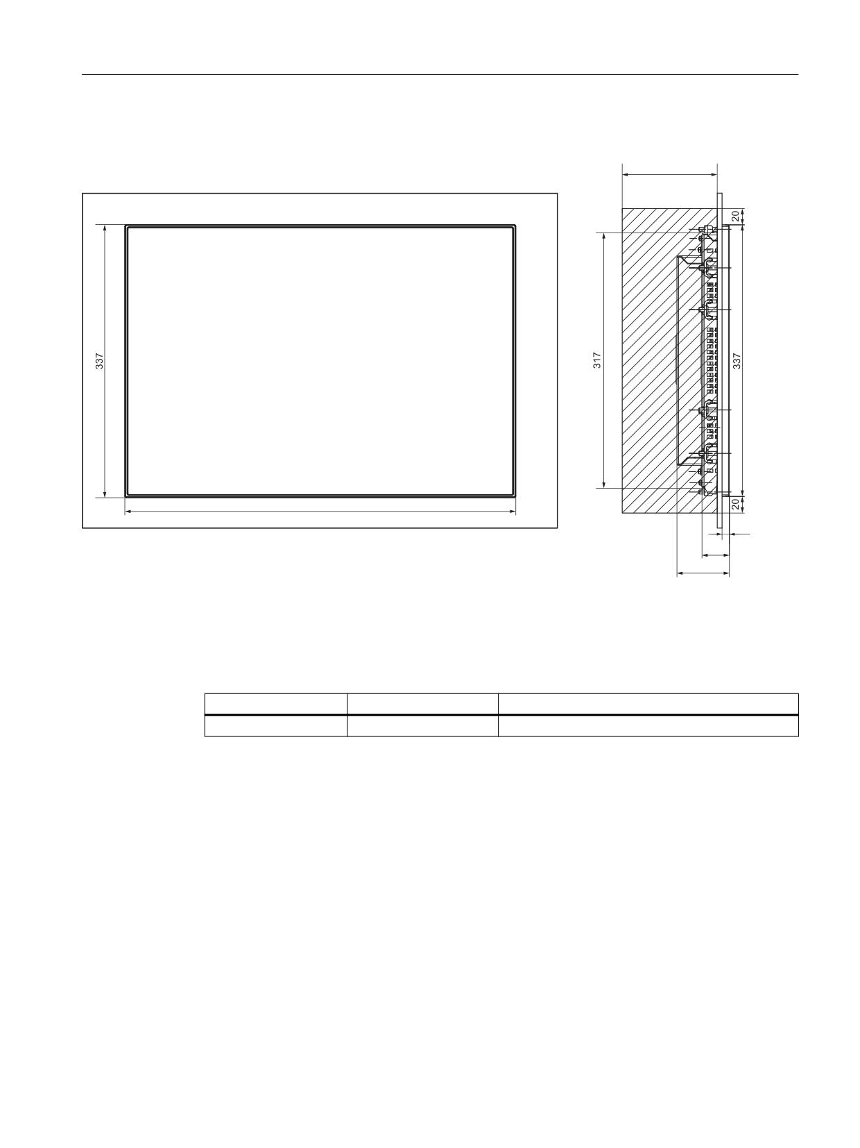
Installation
120*
483
8,9
33,8
64,9
Image 13-3 OP 019 black with TCU (integrated)
* Clearance for cable and ventilation
Table 13-1
Dimensions of the mounting opening
Width (mm)
Height (mm)
Installation depth + ventilation clearance (mm)
465
319
56 + 64
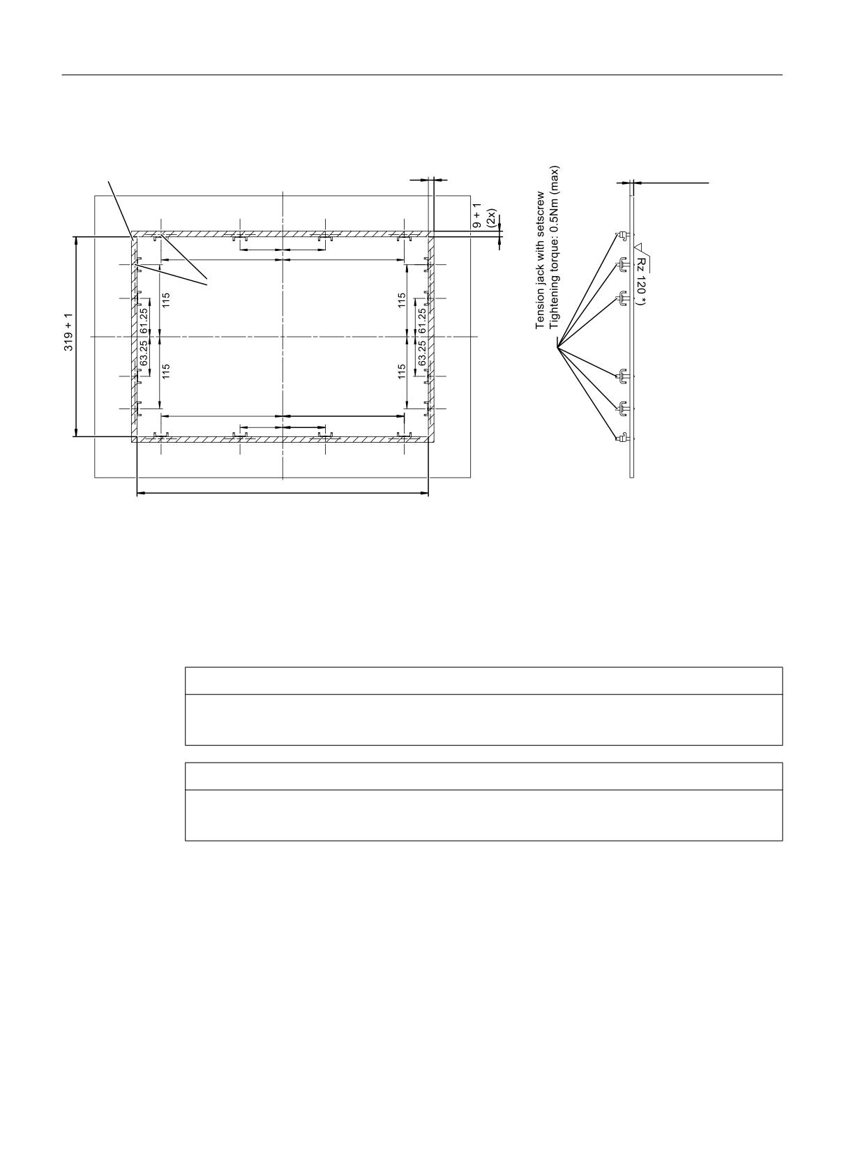
The OP 019 black is mounted using the tension jacks provided (2.5 mm profile; 20 mm long).
When using the tension jacks, holes or threaded holes are not required.
This mounting method also IP65 degree of protection to be achieved if the mounting panel
corresponds to the requirements specified in the dimension drawing. The seal (PU foam seal)
to the mounting panel is already provided on the OP 019 black.
Operator panels
Manual, 03/2016, 6FC5397-1AP40-5BA3
197
Operator panel front: OP 019 black
13.4 Installation
IRU ,3
PLQ
PD[
IRU ,3
PLQ
PD[
6HDO DUHD
[
68.1
68.1
194.1
194.1
3UHVVXUH
SRLQWV IRU
WHQVLRQHUV
194.1
194.1
68.1
68.1
,Q WKH VHDO DUHD
Image 13-4 Dimension sheet for installing the OP 019 black operator panel front
One person installation
You should also observe the data provided in Chapter "General information and networking"
→ "Application planning" → "Climatic and mechanical environmental conditions" → "Cooling".
NOTICE
Impermissible mounting positions can cause malfunctions
Observe the permissible mounting position: Deviating by up to 45º from the vertical.
NOTICE
Damage to the glass front
Do not use suction grippers to lift the glass front.
Operator panels
198
Manual, 03/2016, 6FC5397-1AP40-5BA3
Operator panel front: OP 019 black
13.4 Installation
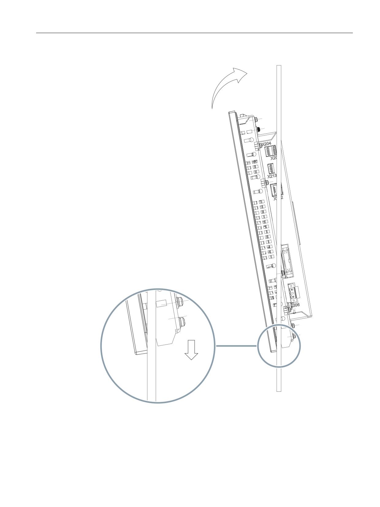
1. Install the operator panel front in the panel cutout from the front.
Image 13-5 Attaching the operator panel
Operator panels
Manual, 03/2016, 6FC5397-1AP40-5BA3
199
Operator panel front: OP 019 black
13.4 Installation
NOTICE
Damage to the sealing
The seal must not be damaged when installing the device so that the maximum achievable
degree of protection can be fulfilled. Therefore, install the OP 019 black centered in the
panel cutout.
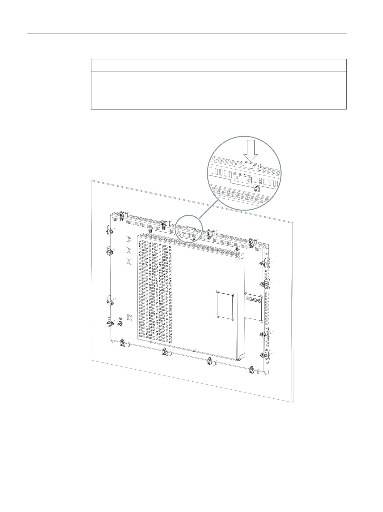
2. Tilt and press the operator panel front into the panel cutout. The catches must be pressed
down.
Image 13-6 Press down on the catch
Operator panels
200
Manual, 03/2016, 6FC5397-1AP40-5BA3
Operator panel front: OP 019 black
13.5 Technical specifications
3. Make sure that the operator panel front sits firmly in the panel cutout and cannot fall out
before you secure it at the rear with the tension jacks.
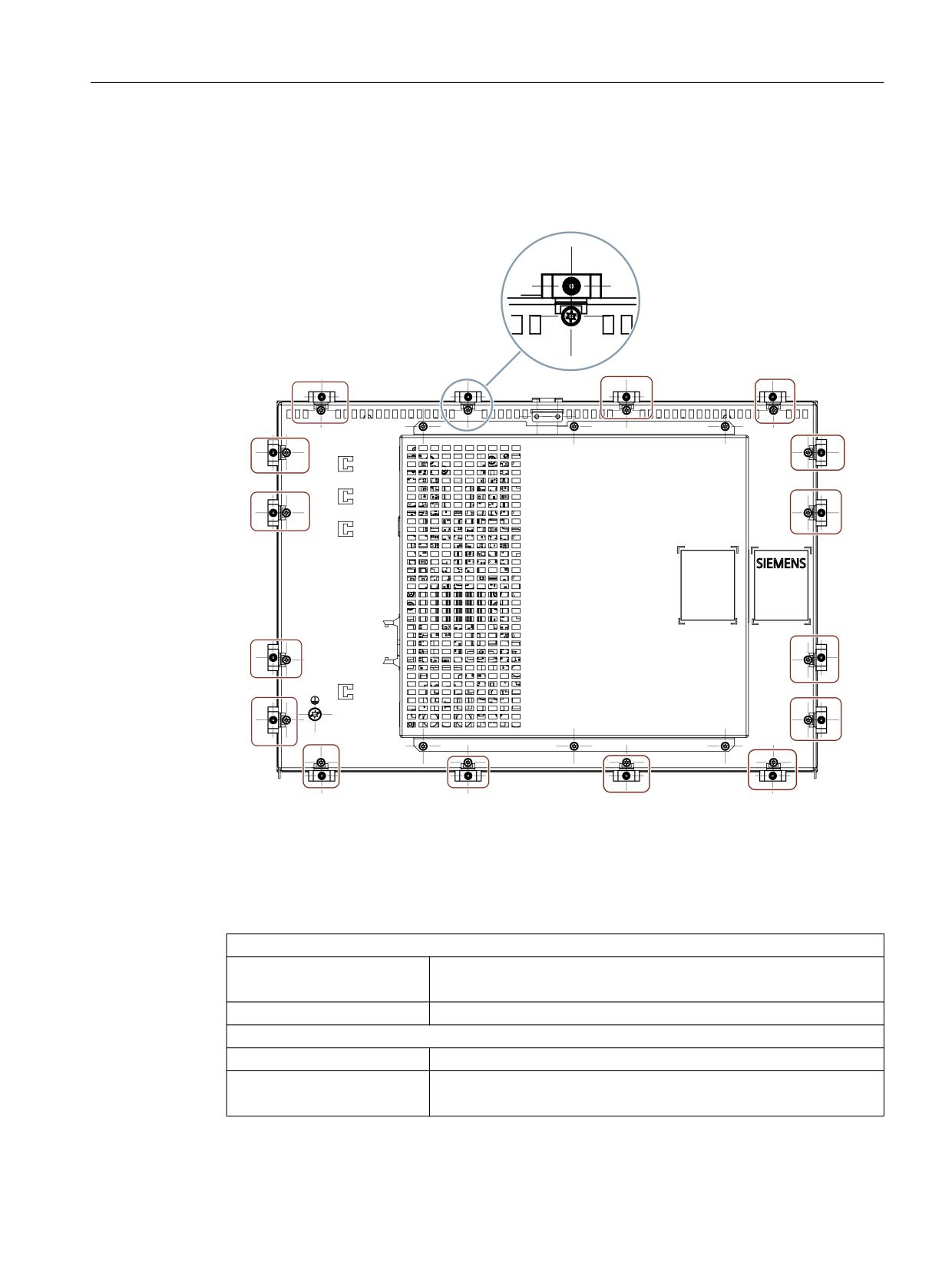
4. Attach the operator panel front in the panel cutout from the rear using the 16 tension jacks
by tightening the setscrews (torque 0.4 - 0.5 Nm).
Image 13-7 Tightening the tension jacks
13.5
Technical specifications
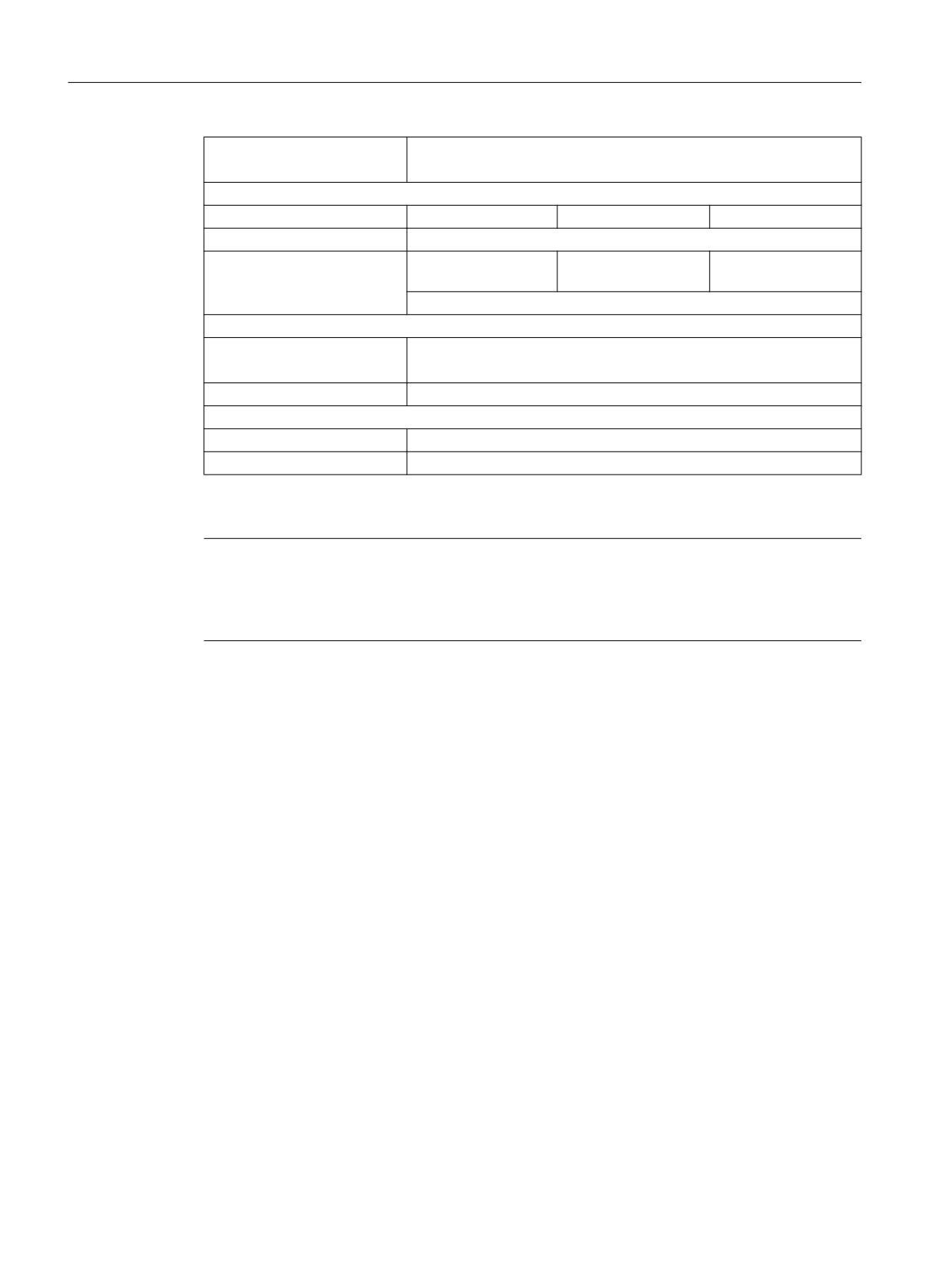
Safety
Degree of protection acc. to
Front side: IP66
EN 60529
Rear side: IP20
Approvals
CE / cULus
Electrical specifications
Power supply 1)
24 VDC (20.4 V ... 28.8 V)
Power consumption
Typical, approx. 1.0 A
Maximum, approx. 2.0 A
Operator panels
Manual, 03/2016, 6FC5397-1AP40-5BA3
201
Operator panel front: OP 019 black
13.6 Spare Parts/Accessories
Power consumption
Typical, approx. 24 W
Maximum approx. 42 W
Mechanical specifications
Dimensions
Width: 483 mm
Height: 337 mm
Depth: 64.9 mm
Weight
Approx. 7.6 kg
Tightening torques, max.
Tension jack screws:
M3 screws:
M4 screws:
0.5 Nm
0.8 Nm
1.8 Nm
M5 grounding screw: 3 Nm
Permissible ambient temperatures
Operation
0 ... 45 °C (front)
0 ... 55 °C (rear)
Storage
-20 to 60° C
Display
Size / resolution
18.5" / 1366 x 768 pixels
MTBF backlight
Minimum 50,000 h at 25º C (dependent on the temperature)
1)
The power supply must be provided as functional extra low-voltage with protective separation (SELV
or according to NEC Class 2).
Note
Information about the climatic and mechanical environmental conditions is contained in the
associated section under:
"General notes and interconnection" → "Operational planning".
13.6
Spare Parts/Accessories
The following can be subsequently ordered for the OP 019 black:
● Spare part: Tension jacks 6FC5248-0AF14-0AA0 (9 units)
● Accessories: USB extension 6FC5347-0AF01-1AA0
Operator panels
202
Manual, 03/2016, 6FC5397-1AP40-5BA3
Direct control key module
14
14.1
Description
The task of the direct key module is to directly transfer the operating signals for the two rows
of keys on the sides of an operator panel front to the control (PLC) without diversion through
intermediate firmware. The signal-to-key assignments are shown in the table and figure in
Section: "Interfaces" → "Operator panel front."
The DKM can be combined with operator panel fronts OP 012, OP 015A and TP 015A.
The DKM converts the key signals to the PROFIBUS DP protocol by means of the ASIC LSPM2
(EN 50170-2, 12 MBaud).
Power is supplied via the operator panel front. The PROFIBUS is completely isolated from the
DKM / operator panel front by means of an opto-coupler and DC/DC converter.
The DKM is operated as a slave on PROFIBUS. The address can be set between 1 and 99
using rotary switches. Two bytes of data are transferred.
In the control, the keys are handled as if they were 16 ordinary digital inputs.
Validity
This description applies to the following components
Designation
Article number
Direct key module (with kit for OP 012)
6FC5247-0AF11-0AA0
Direct key module mounting kit for OP 015A, TP 015A
6FC5247-0AF30-0AA0
14.2
Operating and display elements
On the front of the direct key module there are
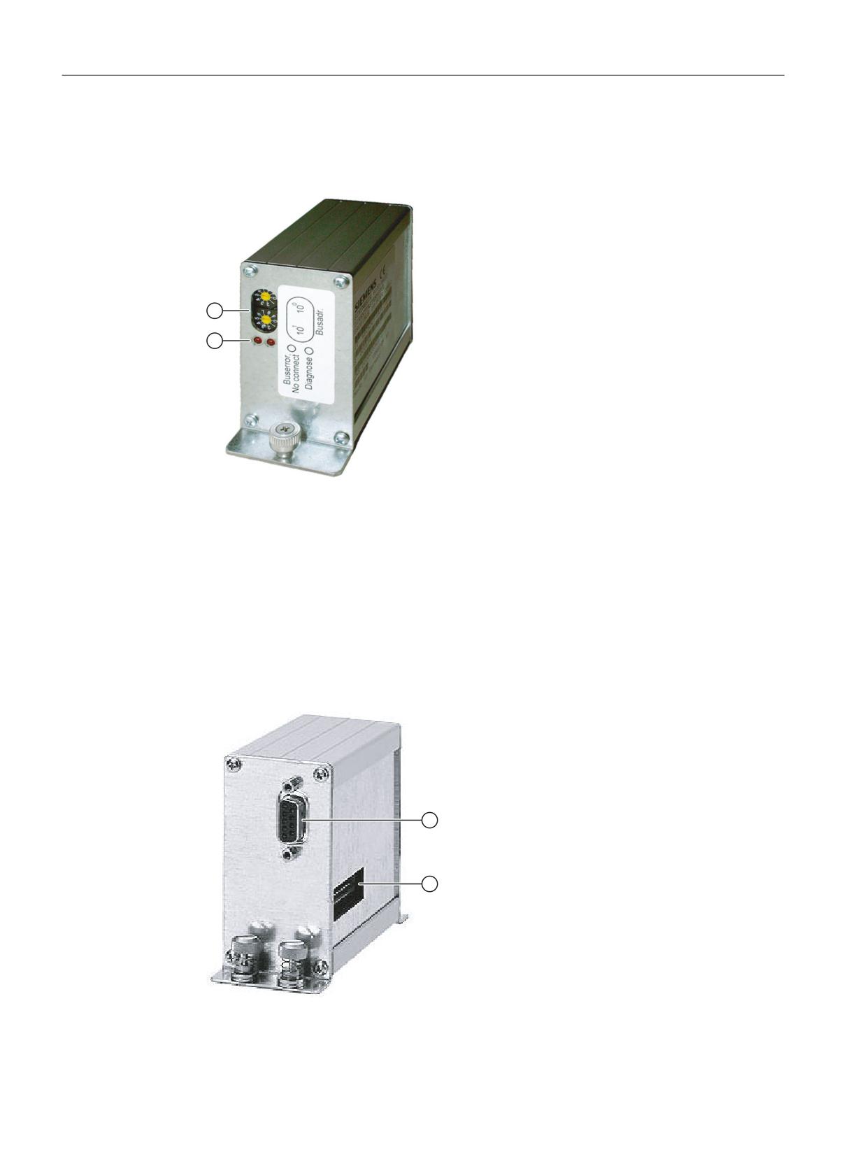
● Top coding switches: One position of the PROFIBUS address
● Coding switch below: Tens position of the PROFIBUS address
Operator panels
Manual, 03/2016, 6FC5397-1AP40-5BA3
203
Direct control key module
14.3 Interfaces
● LED on the left-hand side: If the DKM is not connected to PROFIBUS (or in the event of
another fault), the "bus error" LED lights up.
● LED on the right-hand side: Diagnostics
① Coding switches
② LEDs
Image 14-1 View of the direct key module
14.3
Interfaces
The direct key module has a
● PROFIBUS connection ① and a
● Connection for the direct keys of the operator panel front ②.
Image 14-2 Direct key module with connections
Operator panels
204
Manual, 03/2016, 6FC5397-1AP40-5BA3
Direct control key module
14.4 Mounting
Operator panel connection
The ribbon cable of the operator panel front is inserted through the cut-out in the housing ②.
Here, the switching states of the vertical direct keys can be picked up without intermediate
firmware. These signals can be evaluated by the PLC.
PROFIBUS connection
9-pin connector for connection to an NCU.
Note
The used PROFIBUS cable should have a connector with a straight cable outlet.
Pin assignment
For the pin assignment of the interfaces and other information about the direct keys connection,
refer to Chapter:
"General notes and interconnection" → "Connecting".
14.4
Mounting
14.4.1
Overview
The DKM is installed to one side of the PCU on the operator panel front and connected to the
keyboard controller via a short ribbon cable.
Mounting the DKM requires an installation kit appropriate to the operator panel front used (kit
for the OP 012 already included with the DKM).
The following mounting kit is required for OP 015A and TP 015A:
Operator panels
Manual, 03/2016, 6FC5397-1AP40-5BA3
205

Direct control key module
14.4 Mounting
① Cover plate for keyboard controller for OP 015A
② DKM cable for OP 015A
③ DKM cable for TP 015A
Image 14-3 DKM installation kit for OP 015A and TP 015A
You can find the article number in Section "Description (Page 203)".
14.4.2
Combination with OP 012
The OP 012 outputs the signals from the direct control keys at connector X11, see Auto-
Hotspot.
Preparation
1. Deinstall the PCU (if it is already installed) by removing the knurled-head screws at the four
corners and lifting off the PCU, see Chapter Auto-Hotspot.
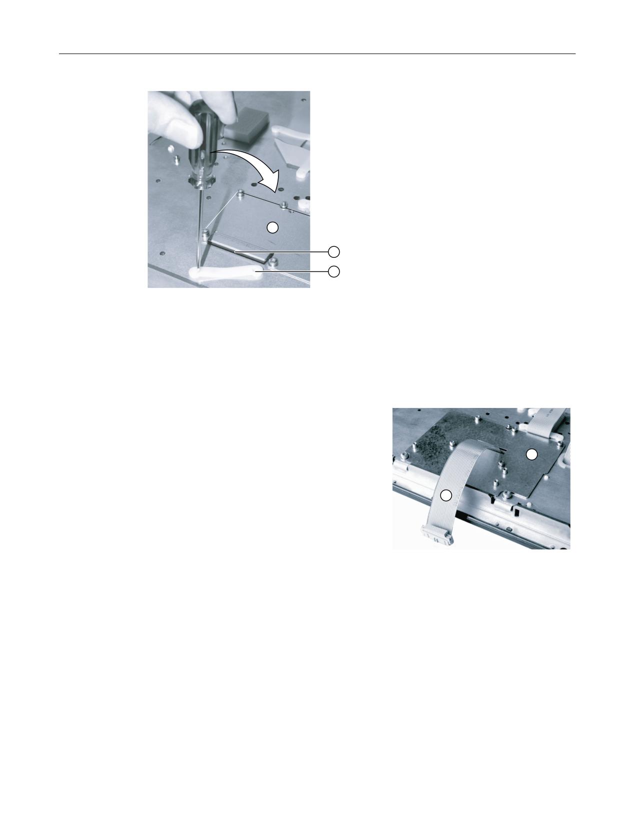
2. Remove the retainer ③ next to the keyboard controller cover plate by inserting a pointed
tool in each of the two slits and loosening the fixing cams by levering in the direction shown.
3. Unscrew the cover plate for the keyboard controller ①. It is no longer needed for assembly.
4. Remove the rubber rim ② from the edge of the housing cutout, which is used to secure a
pushbutton panel cable.
Operator panels
206
Manual, 03/2016, 6FC5397-1AP40-5BA3
Direct control key module
14.4 Mounting
23
① Previous cover plate
② Rubber rim
③ Retainers
Image 14-4 Removing the retainer
Assembly
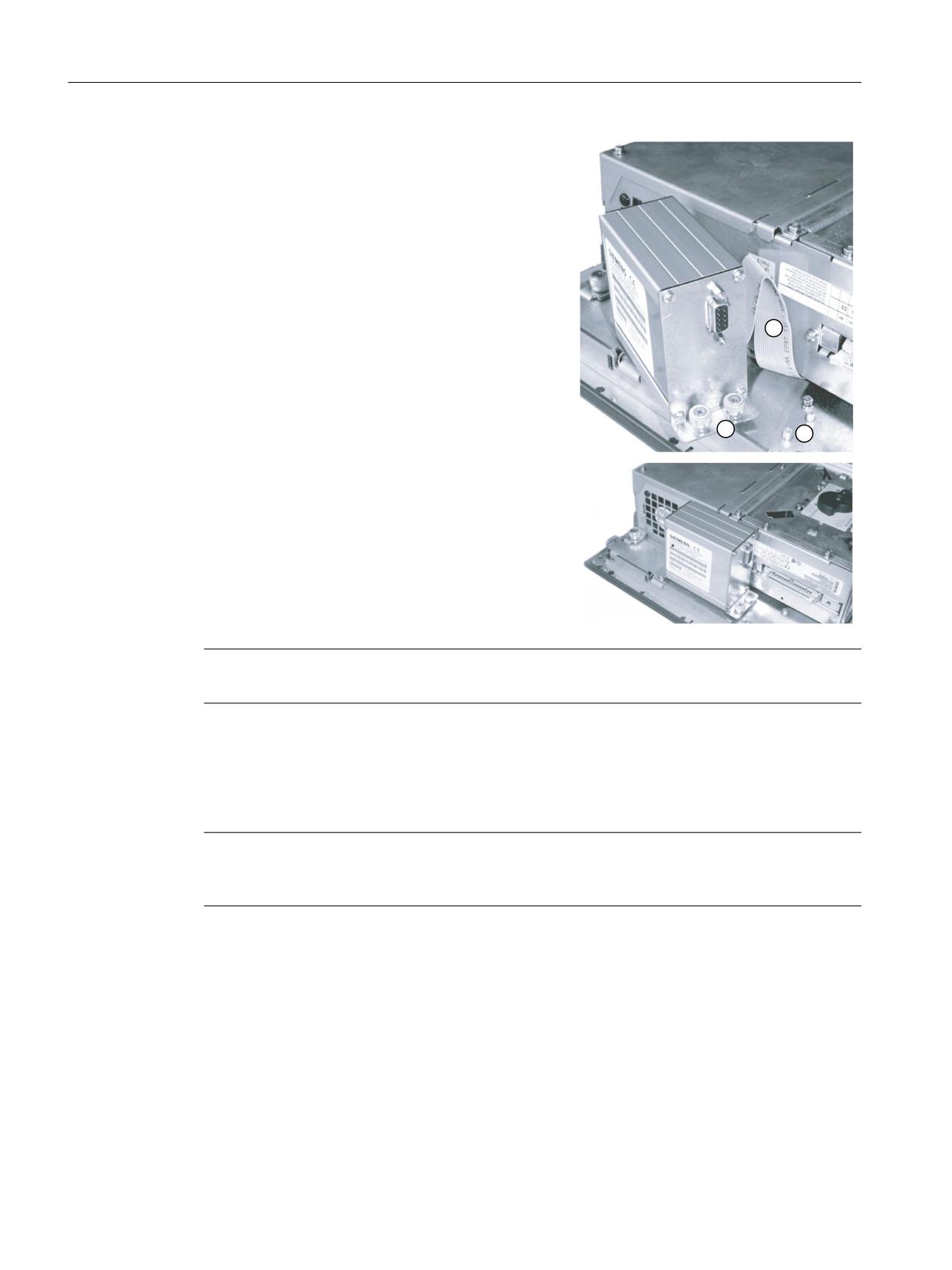
1. Insert the non-rubber-coated end of the ribbon
cable ② supplied with the DKM through the slit
in the cover ① also supplied with the DKM and
into socket X11 on the keyboard controller.
2. Screw down the new cover tightly using the
screws supplied.
3. Mount the PCU as described in Chapter Auto-Hotspot.
4. Set PROFIBUS addresses 01 to 99 using the top (units) and bottom (tens) coding switches
of the DKM (see Image 14-1 View of the direct key module (Page 204)).
Operator panels
Manual, 03/2016, 6FC5397-1AP40-5BA3
207
Direct control key module
14.4 Mounting
5. Connect ribbon cable
① to the DTM.
3&8
6. Screw the DKM firmly to the cover using the two
knurled screws ③ using the fixing nipple ②.
'70
7. Insert the PROFIBUS plug (with straight outgo-
ing cable) into the socket of the DKM.
Note
The direct key module must be removed first on deinstallation of the PCU.
14.4.3
Combination with OP 015A / TP 015A
Note
The installation of the direct key module on the TP 015A is described in the following. The
procedure for assembly with the OP 015A is identical.
Operator panels
208
Manual, 03/2016, 6FC5397-1AP40-5BA3
Direct control key module
14.4 Mounting
Preparation
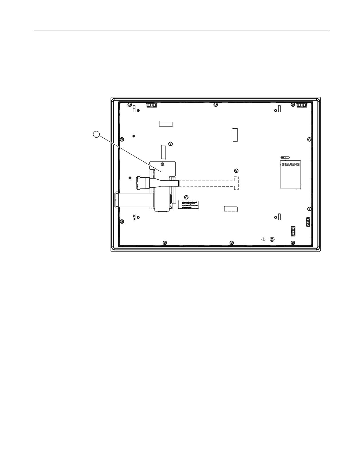
1. Deinstall the PCU (if it is already installed) by removing the knurled-head screws at the four
corners and lifting off the PCU.
2. Unscrew the cover plate for the keyboard controller ①. The plate is required for re-
installation.
① Cover plate for keyboard controller
Image 14-5 TP 015A rear side
Operator panels
Manual, 03/2016, 6FC5397-1AP40-5BA3
209
Direct control key module
14.5 Technical data
Assembly
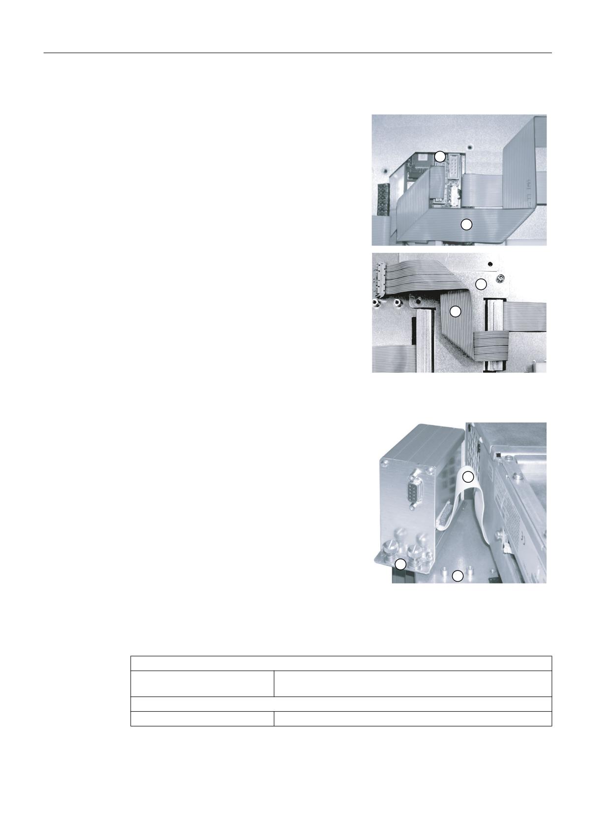
1. Insert DKM ribbon cable ② into socket X11 ①
of the keyboard controller. The cable is already
prefolded.
2. Screw on the cover plate ① and when doing this
fold over the cable ②.
3. Mount the PCU as described in Chapter Auto-Hotspot.
4. Set PROFIBUS addresses 01 to 99 using the top (units) and bottom (tens) coding switches
of the DKM (see Image 14-1 View of the direct key module (Page 204)).
5. Connect ribbon cable ① with the DKM, and
3&8
screw the DKM using the two knurled screws
'70
③ to the securing nipple ②.
14.5
Technical data
Safety
Degree of protection to DIN EN
IP20
60529
Electrical data
Input voltage
5 VDC
Operator panels
210
Manual, 03/2016, 6FC5397-1AP40-5BA3
Direct control key module
14.5 Technical data
Power consumption
Max. 0.75 W
Mechanical data
Dimensions
Width: 106 mm
Height: 42 mm
Depth: 80 mm
Weight
approx. 0.6 kg
Note
Information about the climatic and mechanical environmental conditions is contained in the
associated section under:
"General notes and interconnection" → "Operational planning".
Operator panels
Manual, 03/2016, 6FC5397-1AP40-5BA3
211
Direct control key module
14.5 Technical data
Operator panels
212
Manual, 03/2016, 6FC5397-1AP40-5BA3
PCU 50.5
15
15.1
Description
The powerful SINUMERIK PCU 50.5 not only has an integrated 150 W power supply, but also
all of the interfaces for communication via Ethernet and PROFIBUS (depending on the
particular device) are already on board.
Four USB ports (USB 2.0 Hi-Speed) offer points where a keyboard, mouse and other I/O
devices can be connected.
A covered slot is available for a CompactFlash Card (CF card).
Validity
The description applies to the following devices:
WinXP ProEmbSys (32-bit) operating system
Win7 EmbSys (64-bit) operating system
PCU 50.5-C
PCU 50.5-P
PCU 50.5-C
PCU 50.5-P
Article number
6FC5210-0DF52-2AA0
6FC5210-0DF53-2AA0
6FC5210-0DF52-3AA0
6FC5210-0DF53-3AA0
Processor
Celeron 1.8 GHz
Core i5 2.4 GHz
Celeron 1.8 GHz
Core i5 2.4 GHz
Work memory
1024 MB
2048 MB
4096 MB
8192 MB
Mass storage
40 GB
40 GB
80 GB
80 GB
PROFIBUS DP
Yes
No
No
No
Slots
2 x PCI
PCI + PCIe x16
PCI + PCIe x16
PCI + PCIe x16
Features
● Robust design (continuous operation, high noise immunity)
● The installation location and length vary due to the different types of mounting and mounting
brackets
● Can be expanded using two plug-in boards (min. 140 mm up to max. 185 mm long)
● For diagnostics (e.g. for operation without a monitor), two 7-segment displays, status LEDs
and one service switch with power button are integrated.
● Graphic: QM57 Express chipset
● Work memory (with ECC):
- For WinXP: Max. 4 GB
- For Win7: Max. 8 GB
● Mass storage: Electronic SSD drive
Operator panels
Manual, 03/2016, 6FC5397-1AP40-5BA3
213
PCU 50.5
15.1 Description
● Screen resolutions, CRT monitor:
- Up to 1280 x 1024 at 100 Hz / 32-bit color depth
- Up to 1600 x 1200 at 60 Hz / 32-bit color depth
- Max. resolution: 2038 x 1536 at 75 Hz / 16-bit color depth
● Screen resolution, LCD monitor via DVI: 1600 x 1200 at 60 Hz / 32-bit color depth
● Power supply: 24 VDC, max. 210 W with on/off switch
● Connections:
- PROFIBUS (max. 12 Mbit/s, isolated, compatible with CP 5611, optional)
- DVI-I interface for external monitor
-
2 x Ethernet 10/100/1000 Mbit/s
–
4 x USB 2.0 Hi-Speed High-Current
– Serial interface COM1 (RS 232C)
Operator panels
214
Manual, 03/2016, 6FC5397-1AP40-5BA3
PCU 50.5
15.1 Description
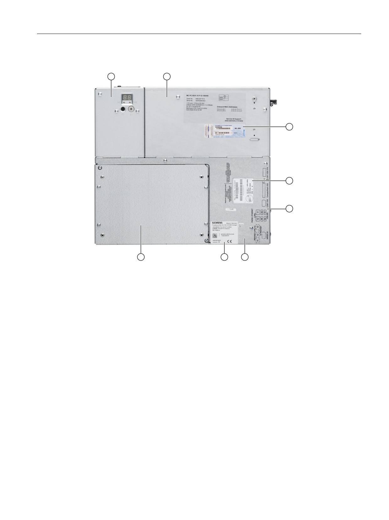
View
① Housing cover, service module
② Housing cover, motherboard
③ Windows license label
④ Rating plate for power supply
⑤ Print for the interfaces on the right-hand side of the housing
⑥ Housing cover, power supply
⑦ Ratingplate PCU
⑧ Housing cover, SSD
Image 15-1 Top view of PCU 50.5
Operator panels
Manual, 03/2016, 6FC5397-1AP40-5BA3
215
PCU 50.5
15.2 Operator control and display elements
15.2
Operator control and display elements
15.2.1
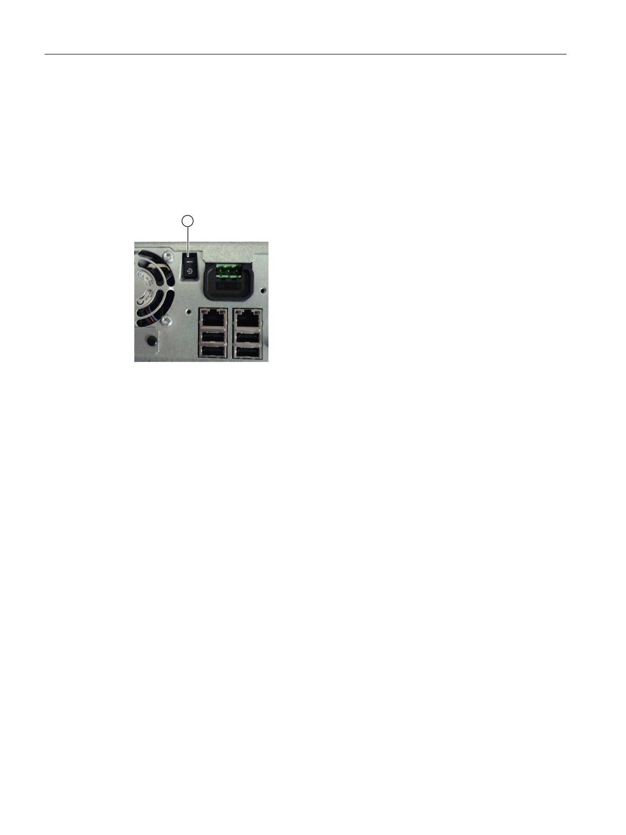
On/off switch
On/Off switch
Image 15-2 PCU 50.5 On/off switch
The integrated 24 V power supply for the PCU is switched on and off using the on/off switch
①. It also serves as a substitute for the reset button, which is no longer provided, see Switching
off / reset (Page 248).
Operator panels
216
Manual, 03/2016, 6FC5397-1AP40-5BA3
PCU 50.5
15.2 Operator control and display elements
15.2.2
Service module
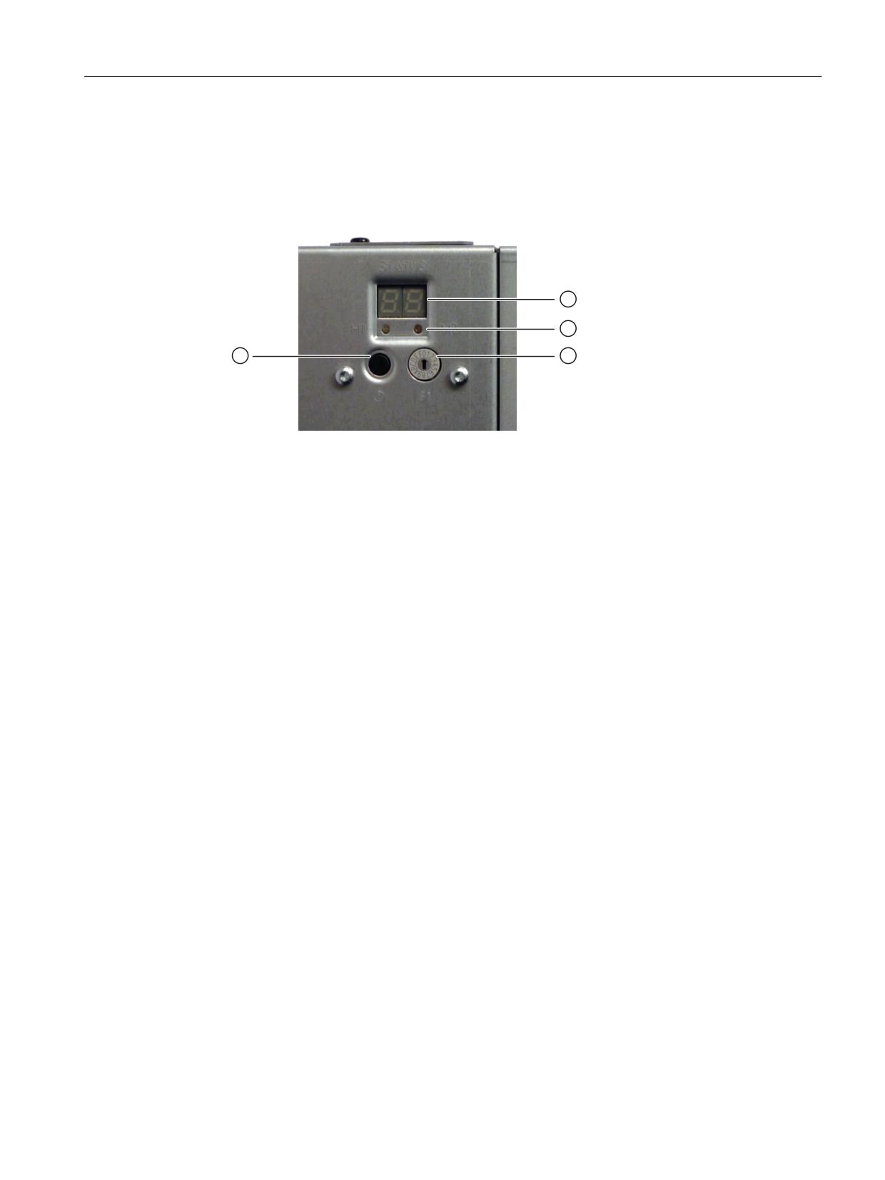
The service module is located, depending on the device mounting, at two positions:
● Side panel, next to the equipment fan for upright mounting in the control cabinet
● Cover above the equipment fan for standard installation in the operator panel
①
2 x 7-segment display
②
2 x LED: Diagnostics display H1 and H2
③ Service switch
④ Power button
Image 15-3 Service module
7-segment display
● When the device is switched on, a HW self-test of the service module is first carried out;
Code 88 is output in the process.
● While the BIOS boots, the PCU base software runs through a self test, where the codes of
the corresponding test step are displayed. Code 00 is displayed if booting is completed
without any error. The code of the most recently started test step is displayed when an error
occurs. See BIOS beep codes (Page 258).
● Display of the service switch positions.
● Codes of applications can also be displayed if required.
LEDs H1 and H2
● While the BIOS boots, the two LEDs light up in two colors (red and green) in order to test
their operation. The two LEDs switch off when booting is completed without errors.
● Applications can control the two LEDs if required.
The diagnostics displays display the following information:
● The diagnostics display "H1" displays status codes of the PCU-Basesoftware.
● The diagnostics display "H2" is assigned to the application software.
The meaning of the displayed status codes depends on whether the PCU 50.5 is in system
startup (Page 261) mode, running mode (Page 262), or shutdown (Page 262) mode.
Operator panels
Manual, 03/2016, 6FC5397-1AP40-5BA3
217
PCU 50.5
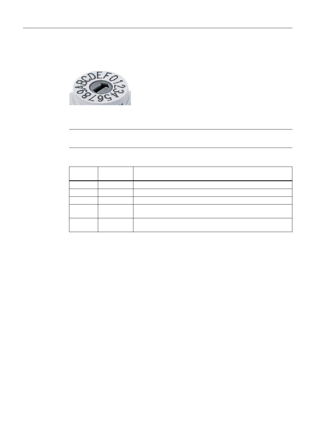
15.2 Operator control and display elements
Service switch
The service switch is a rotary switch with 16 possible positions.
The following table provides an overview of the switch positions. When delivered, the switch
is in position "0": Normal operation
Note
A change of the switch position only becomes effective after the next restart.
Selector
Mode
Function
position
0
Normal operation (default setting)
6
-
Reserved for end users
B
Service
Performing a BIOS recovery after a failed update.
9
Service
Restore the default values automatically at the next boot (e.g. with BIOS
update or SSD replacement).
E
Service
After a restart, booting is preferably from another storage medium (e.g.
USB flash drive) as from the installed SSD.
The PCU base software is capable of reading out the switch positions if this was set beforehand
in the BIOS setup. The default setting is "evaluate (Operation mode switch -> Enabled)".
Power button
The power button is located below the diagnostics display; it can be used to start up and shut
down the Windows operating system. This means that the power button is an alternative to
the on/off switch.
Additional references
For details on diagnostics and service, refer the to the following manual:
Basic Software and Operating Software Commissioning Manual (IM8)
Operator panels
218
Manual, 03/2016, 6FC5397-1AP40-5BA3
PCU 50.5
15.3 Interfaces
15.3
Interfaces
15.3.1
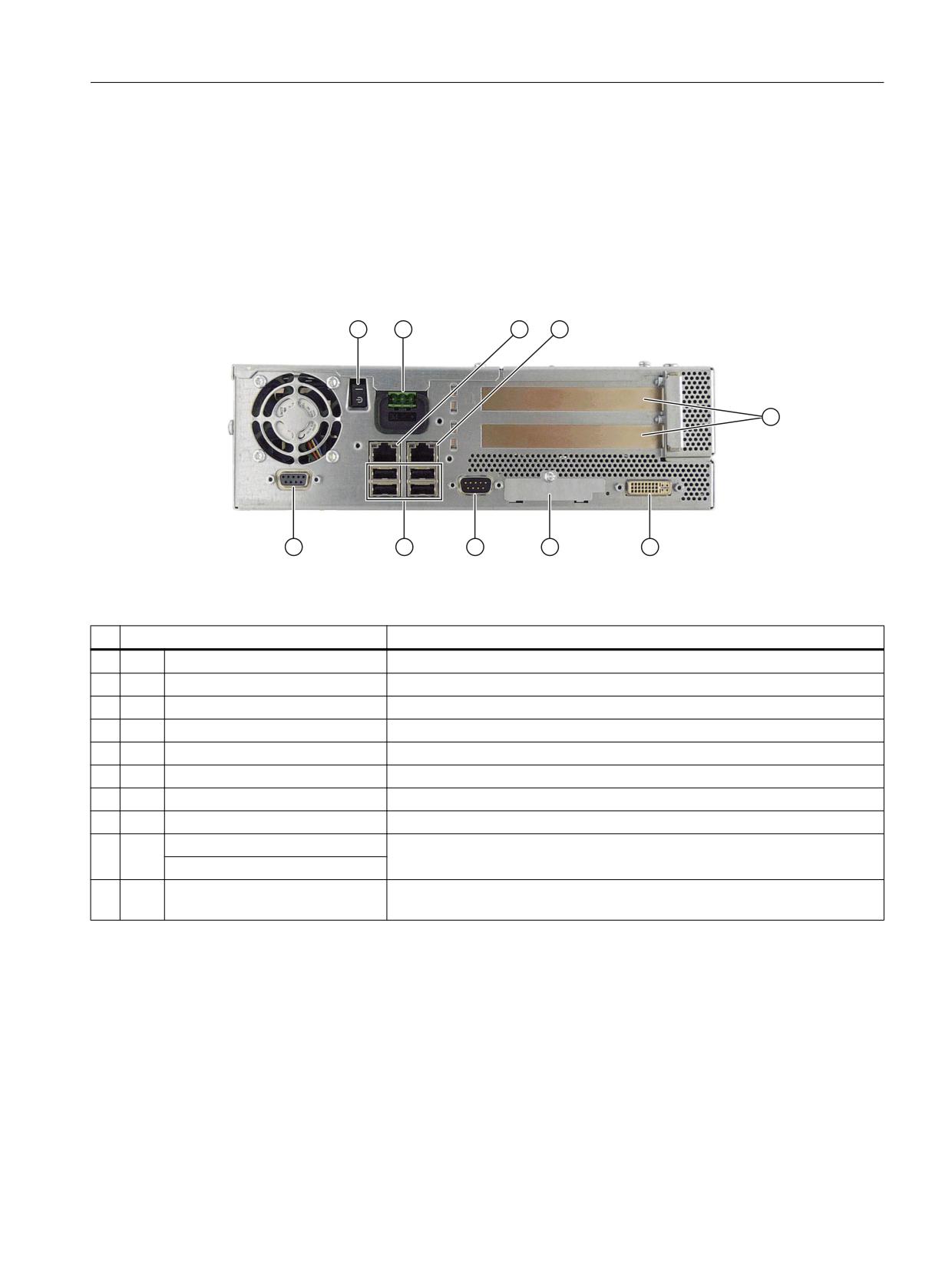
External interfaces
Right-hand housing side
Image 15-4 PCU 50.5 side view from the right with interfaces (without plug-in card)
Interface/connection
Function
①
S0
Line side switch
On/Off switch (only standby) for the power supply unit
②
X0
Power supply
24 VDC (SELV)
③
X2
Ethernet 2
10/100/1000 Mbit/s, connection for the system network (e.g. operator panels)
④
X1
Ethernet 1
10/100/1000 Mbit/s, connection for the company network (LAN)
⑤
PCI slot (Slot 1 / Slot 2)
2 slots for expansion modules
⑥
X70
DVI-I interface
Bus for external monitor (VGA monitors via optional adapter)
⑦
X50
CompactFlash card
Slot for CF card under cover plug, not hot-plug capable
⑧
X30
COM1 (V.24)
Serial interface, e.g. for a modem
⑨
X60
USB port 1 / 2
4 external USB connections (USB 2.0 Hi-Speed type A) - max. 2 can be
operated at the same time as High-Current *)
USB port 3 / 4
⑩
X4
PROFIBUS DP/MPI
12 MBit/s connection for connecting an S7 automation unit, isolated (only for
PCU 50.5-C with WinXP)
*)
The max. current carrying capacity of the four USB connections is a total of 1.2 A.
The max. current carrying capacity of a USB connection is 500 mA.
Operator panels
Manual, 03/2016, 6FC5397-1AP40-5BA3
219
PCU 50.5
15.3 Interfaces
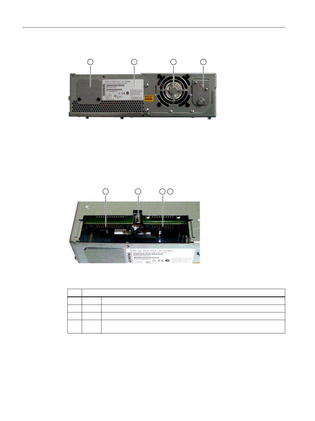
Left-hand housing side
① Cover plate with retaining screws
② Rating plate of the PC unit
③ Device fan
④ Cover plate for battery
Image 15-5 Side view of the PCU 50.5 from left
Housing rear
Image 15-6 PCU 50.5 interfaces for connecting operator panel fronts
Interface/connection
①
X44
I/O interface for connecting the I/O cable of the operator panel front
②
X42
Optional connection for operator panel fronts with USB 2.0 Hi-Speed front interface
③
X400
1. LVDS interface for connecting a TFT display cable
④
X401
Access for 2nd LVDS interface for Dual LVDS display (e.g. OP 19) - located behind
X400 (can be accessed when the SSD module is removed)
Operator panels
220
Manual, 03/2016, 6FC5397-1AP40-5BA3
PCU 50.5
15.3 Interfaces
Pin assignment for external interfaces
In principle you will find the pin assignments of the individual external interfaces in "General
information and networking", Section "Connecting", except for:
● PCI slots: See Connector assignment of bus board (Page 226).
● CompactFlash card: See the description in Chapter "Keyboards and additional
components".
Operator panels
Manual, 03/2016, 6FC5397-1AP40-5BA3
221
PCU 50.5
15.3 Interfaces
15.3.2
Internal interfaces
15.3.2.1
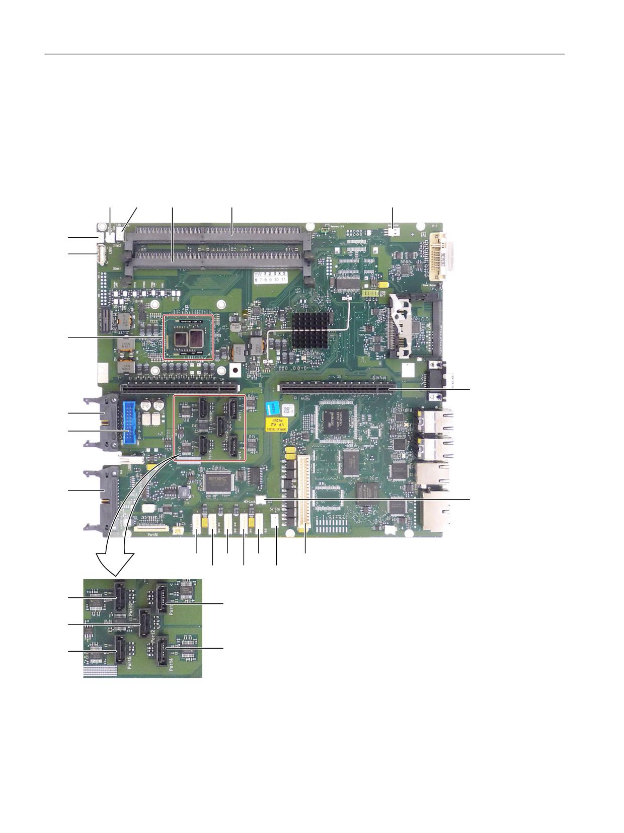
Connector assignment of motherboard
Overview
;
;
;
;
;
;
;
;
;
;
;
;
;
;
;
;
;
;
;
;
;
;
;
;
;
Image 15-7 PCU 50.5 - motherboard interfaces
Operator panels
222
Manual, 03/2016, 6FC5397-1AP40-5BA3

PCU 50.5
15.3 Interfaces
Connector
Interface
Description
X1
Processor
X10
Bus expansion
Socket for bus expansion, uses PCI bus signals
X13
Power supply
20-pin connection plug for power supply
X19 / X20
Memory
2 x SDRAM DDR3 with ECC
X24
Backup battery
Power supply for backup battery, 2-pin male connector
X26
SATA 4 (optional)
X27
SATA 3 (optional)
X28
Power supply
Power supply for serial ATA
SATA 2
X29
SATA 1
X30
SATA 0
X50
SATA 0
X51
SATA 1
X52
Serial ATA
Data cable for serial ATA
SATA 2
X53
SATA 3 (optional)
X54
SATA 4 (optional)
X3
HD-lock
Interlock identification for the optional MC hard disk module
SATA
X131
Connection for PS fan
Power supply for CPU fan, 3-pin male connector
X132
Connection for device fan
Power supply for device fan, 3-pin male connector
X2400
Tap for backup battery
Voltage tap ( = 3V) of the backup battery, 2-pin, male con-
nector
X44
I/O interface
Connection of the I/O cable of the operator panel front
X400
1st LVDS interface
Connection of the display cable
X401
2nd LVDS interface
Additional display interface K3 for OP019
X71
RS485-SYNC (opt.)
Synchronizing several PCI boards to a common system clock
cycle
Signal type:
I
Input
O
Output
V
Power supply
-
Ground (reference potential) or N.C. (not connected)
Operator panels
Manual, 03/2016, 6FC5397-1AP40-5BA3
223
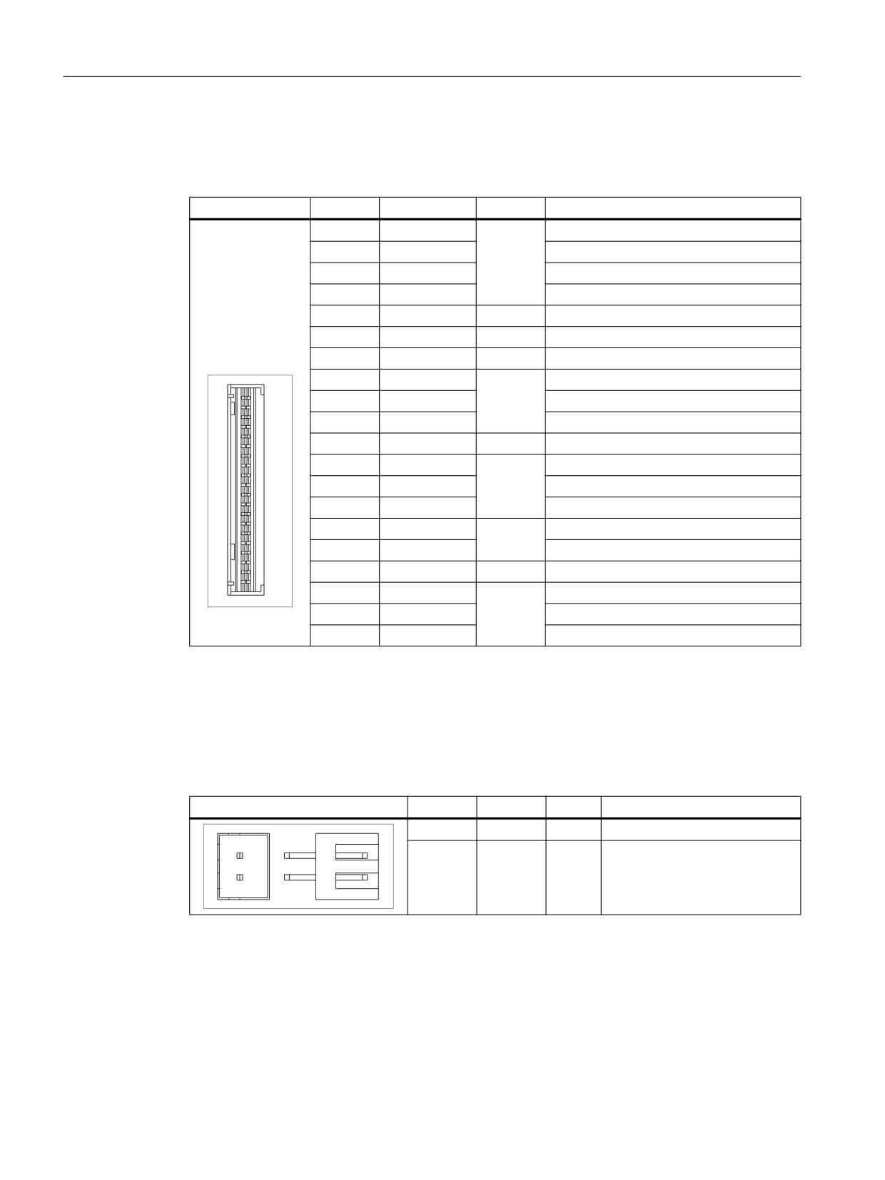
PCU 50.5
15.3 Interfaces
DC interface of the power supply X13
Table 15-1
X13 connector assignment
Connector
Pin
Name
Type
Remark
1
P5V
+5 V
2
P5V
+5 V
3
P5V
V
+5 V
4
P5V
+5 V
5
P5V Sense
O
Sense 5 V
6
PS_NAU_N
Power loss early warning signal
7
PS_PWROK
Power Good Signal
8
GND
Ground
9
GND
-
Ground
10
GND
Ground
11
N12V
V
-12 V
12
GND
Ground
13
GND
-
Ground
14
GND
Ground
15
P12V
+12 V
V
16
P12V
+12 V
17
P3V Sense
O
Sense 3.3 V
18
P3V
+3.3 V
19
P3V
V
+3.3 V
20
P3V
+3.3 V
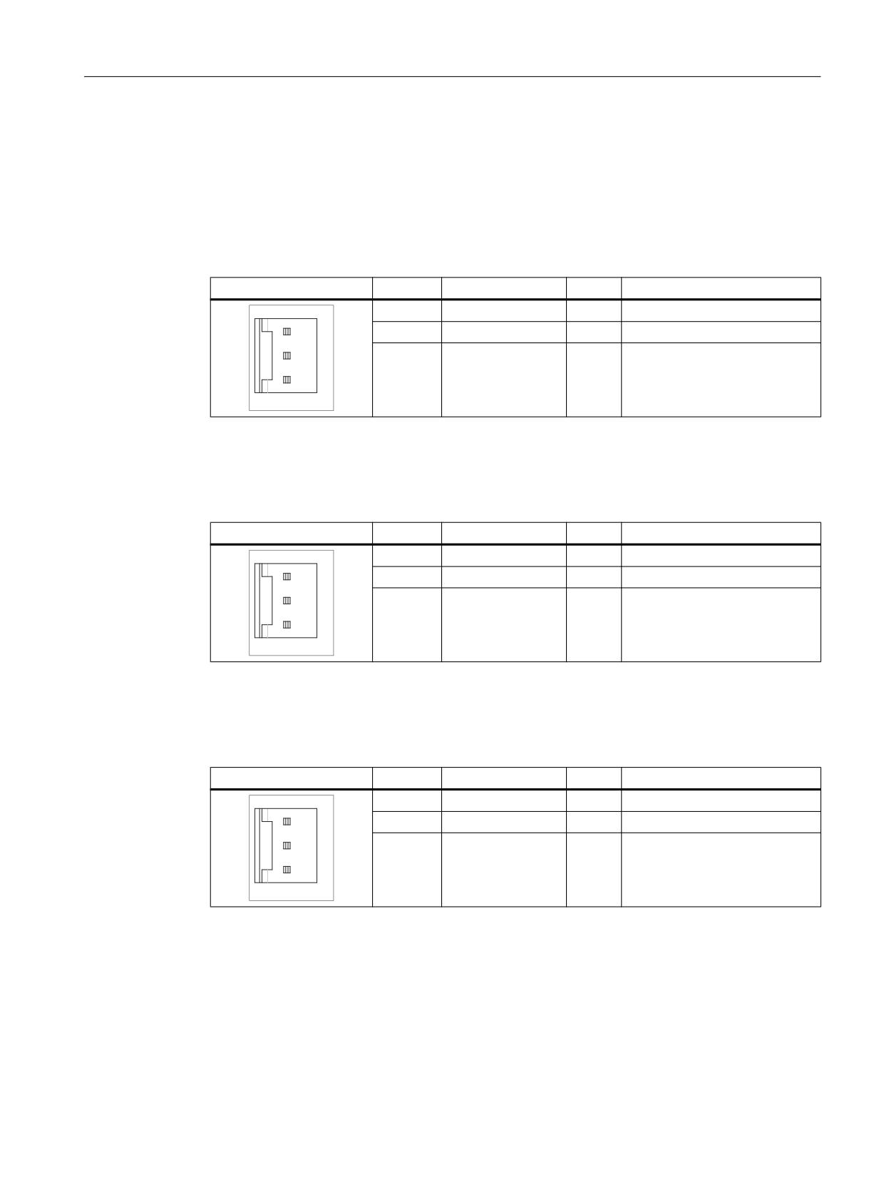
Connector for backup battery X24
The battery for backing up the CMOS-RAM is connected to this connection.
A 3V lithium battery with a capacity of 750 mAh is used for this purpose.
Table 15-2
Assignment of the X24 connector
Connector
Pin
Name
Type
Remark
1
+
VI
Plus pole
2
-
VI
Minus pole
Operator panels
224
Manual, 03/2016, 6FC5397-1AP40-5BA3
PCU 50.5
15.3 Interfaces
SYNC interface for PCI expansion modules X71
Using this interface, several PCI boards can synchronize to a common system clock (Global
Control Telegram clock cycle duration of PROFIBUS DP operated in the isochronous mode).
Their SYNC interfaces must be connected with one another using a looped through cable. The
system clock transfer to the interface is realized differentially (RS485 signals).
Table 15-3
Pin assignment of connector X71
Connector
Pin
Name
Type
Remark
1
NC
-
Ground via 100K
2
XSYNC
I/O
Negated clock signal
3
SYNC
I/O
Clock signal
Connection for power supply fan X131
Table 15-4
Pin assignment of connector X131
Connector
Pin
Name
Type
Remark
1
GND
-
Ground (reference potential)
2
+12 V
V
Switched voltage supply
3
PG1 FAN_CLK
I
Clock signal
Connection for device fan X132
Table 15-5
Pin assignment of connector X132
Connector
Pin
Name
Type
Remark
1
GND
-
Ground (reference potential)
2
+12 V
V
Switched voltage supply
3
CPU FAN_CLK
I
Clock signal
Operator panels
Manual, 03/2016, 6FC5397-1AP40-5BA3
225
PCU 50.5
15.3 Interfaces
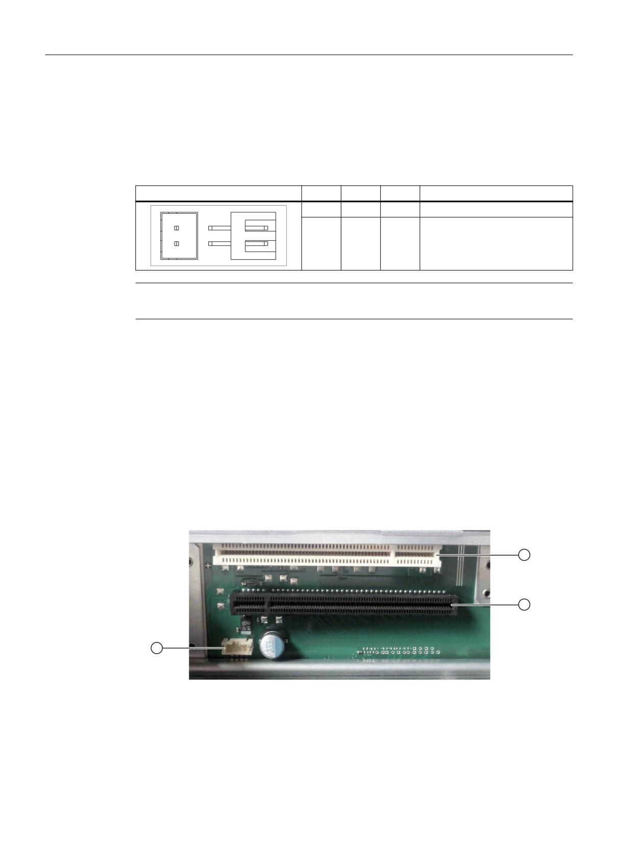
Tap for backup battery X2400
This connection is intended for expansion modules with their own CMOS-RAM.
The voltage of the backup battery can be tapped here to back up the CMOS-RAM data of the
expansion module.
Table 15-6
Assignment of connector X2400
Connector
Pin
Name
Type
Remark
1
+
VO
Plus pole of battery over 100 Ohm
2
-
VO
Minus pole
Note
No battery should be connected to this connection.
15.3.2.2
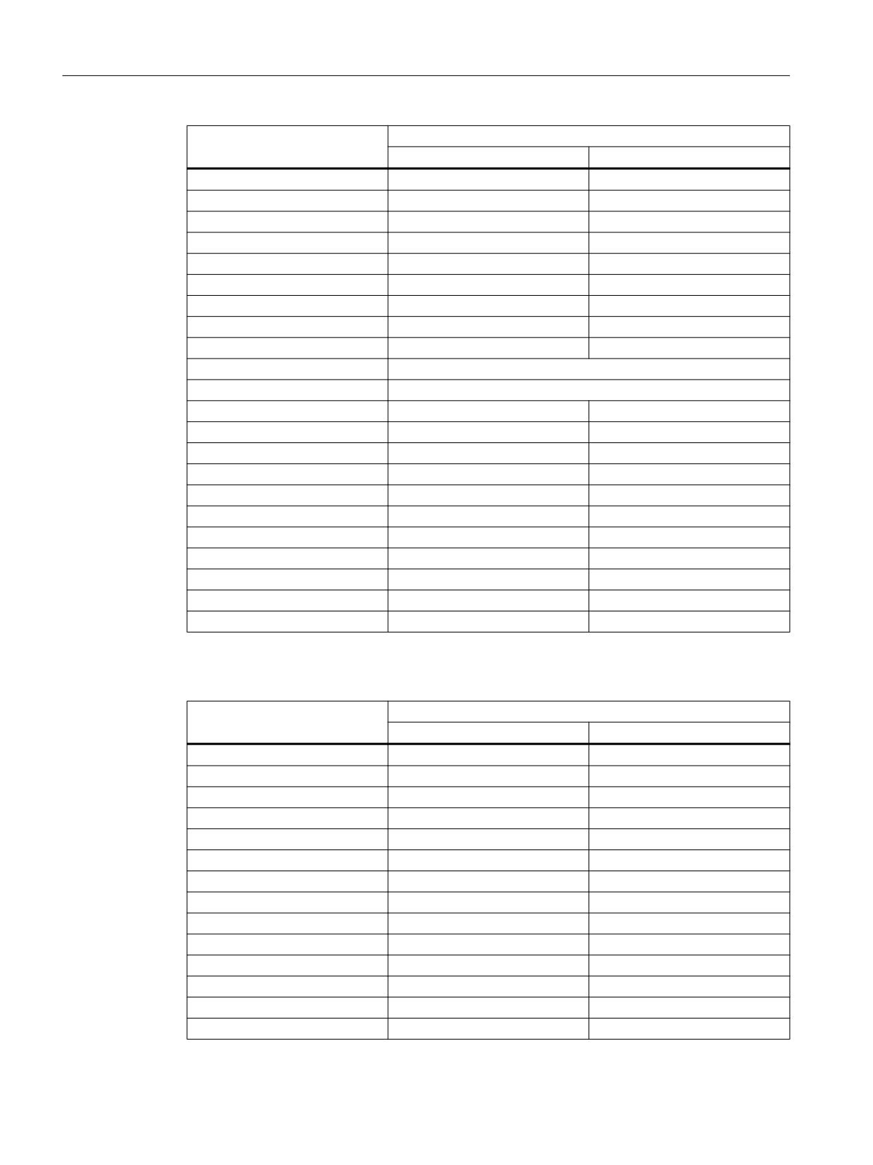
Connector assignment of bus board
The bus board is designed as a link between the motherboard and the expansion modules. It
is mounted using two screws. The expansion modules are supplied with power via the bus
PCB to motherboard connection.
● The bus PCB has two PCI slots (max. 185 mm long).
● Expansion modules for 5 V and 3.3 V according to the following PCI specification can be
installed.
- PCI: Rev. 2.2
- PCIe x16: Rev. 1.0
● All PCI slots support the master mode.
① Slot 1 PCI
② Slot 2 PCI Express x16
③
12 V power supply connection for WinAC module
Image 15-8 Bus PCB PCU 50.5-P
Operator panels
226
Manual, 03/2016, 6FC5397-1AP40-5BA3

PCU 50.5
15.3 Interfaces
PCI slot pin assignment
5V System Environment
Side B
Side A
1
- 12 V
TRST#
2
TCK
+ 12 V
3
Ground
TMS
4
TDO
TDI
5
+5V
+5V
6
+5V
INTA#
7
INTB#
INTC#
8
INTD#
+5V
9
PRSNT1#
Reserved
10
Reserved
+5V (I/O)
11
PRSNT2#
Reserved
12
Ground
Ground
13
Ground
Ground
14
Reserved
Reserved
15
Ground
RST#
16
CLK
+5V (I/O)
17
Ground
GNT#
18
REQ#
Ground
19
+5V (I/O)
Reserved
20
AD[31]
AD[30]
21
AD[29]
+ 3.3 V
22
Ground
AD[28]
23
AD[27]
AD[26]
24
AD[25]
Ground
25
+ 3.3 V
AD[24]
26
C/BE[3]#
IDSEL
27
AD[23]
+ 3.3 V
28
Ground
AD[22]
29
AD[21]
AD[20]
30
AD[19]
Ground
31
+ 3.3 V
AD[18]
32
AD[17]
AD[16]
33
C/BE[2]#
+ 3.3 V
34
Ground
FRAME#
35
IRDY#
Ground
36
+ 3.3 V
TRDY#
37
DEVSEL#
Ground
38
Ground
STOP#
39
LOCK#
+ 3.3 V
40
PERR#
SDONE
Operator panels
Manual, 03/2016, 6FC5397-1AP40-5BA3
227
PCU 50.5
15.3 Interfaces
5V System Environment
Side B
Side A
41
+ 3.3 V
SBO#
42
SERR#
Ground
43
+ 3.3 V
PAR
44
C/BE[1]#
AD[15]
45
AD[14]
+ 3.3 V
46
Ground
AD[13]
47
AD[12]
AD[11]
48
AD[10]
Ground
49
Ground
AD[09]
50
CONNECTOR KEY
51
CONNECTOR KEY
52
AD[08]
C/BE[0]#
53
AD[07]
+ 3.3 V
54
+ 3.3 V
AD[06]
55
AD[05]
AD[04]
56
AD[03]
Ground
57
Ground
AD[02]
58
AD[01]
AD[00]
59
+5V (I/O)
+5V (I/O)
60
ACK64#
REQ64#
61
+5V
+5V
62
+5V
+5V
Connector assignment, PCI Express slot x16
5V System Environment
Side B
Side A
1
P12V
PRSNT1_N
2
P12V
GND
3
P12V
P12V
4
GND
GND
5
SMBCLK
PTCK
6
SMBDAT
PTDI
7
GND
PTDO
8
P3V3
PTMS
9
PTRST_N
P3V3
10
Aux_3V3
P3V3
11
PCIE_Wake_N
PCI RST_N
12
Reserved
GND
13
GND
GND
14
PCIE_TX_P(1)
GND
Operator panels
228
Manual, 03/2016, 6FC5397-1AP40-5BA3
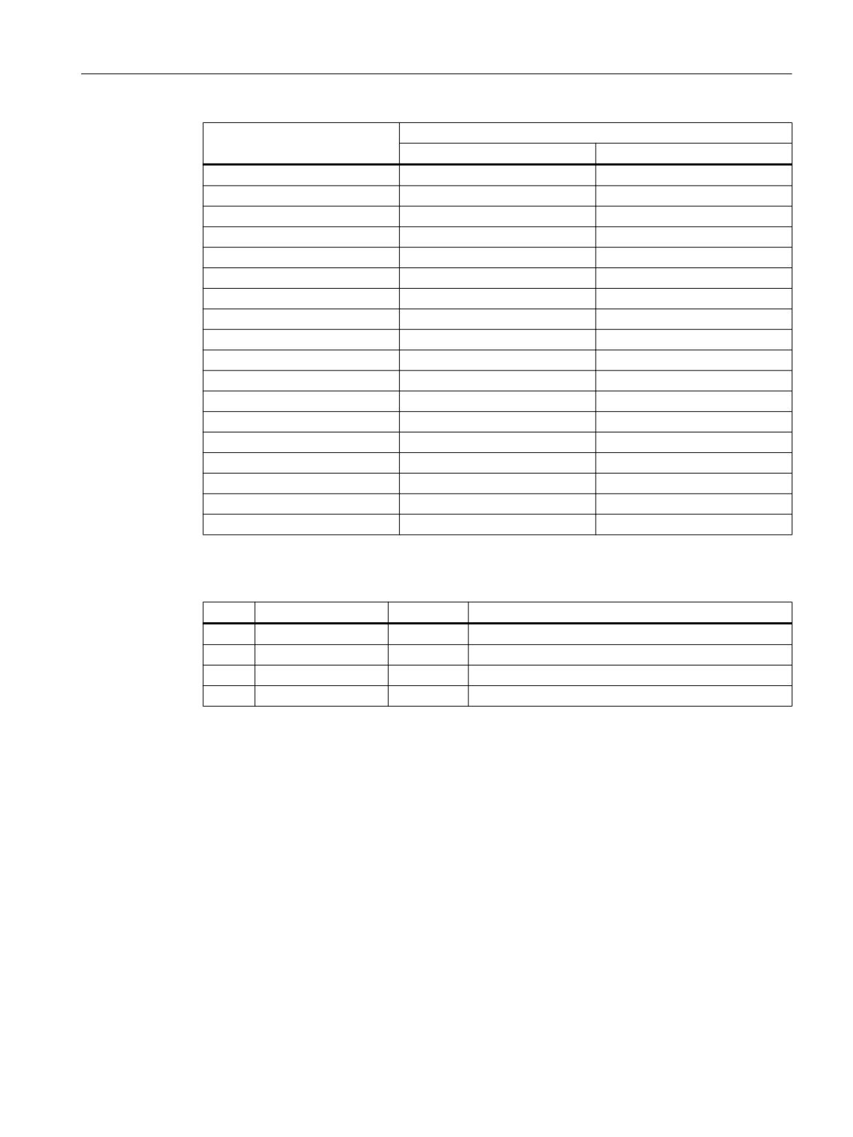
PCU 50.5
15.3 Interfaces
5V System Environment
Side B
Side A
15
PCIE_TX_N(1)
GND
16
M
PCIE_RX_P(1)
17
PRSNT2_N
PCIE_RX_N(1)
18
GND
GND
19
PCIE_TX_P(2)
Reserved
20
PCIE_TX_N(2)
GND
21
GND
PCIE_RXP(2)
22
GND
PCIE_RX_N(2)
23
PCIE_TX_P(3)
GND
24
PCIE_TX_N(3)
GND
25
GND
PCIE_RX_P(3)
26
GND
PCIE_RX_N(3)
27
PCIE_TX_P(4)
GND
28
PCIE_TX_N(4)
GND
29
GND
PCIE_RX_P(4)
30
GND
PCIE_RX_N(4)
31
PRSNT2_N
GND
32
GND
Reserved
Pin assignment 12V power supply connection for WinAC module
Pin
Name
Signal type
Remark
1
+ 12 V
V
12 V voltage
2
GND
-
Ground (reference potential)
3
GND
-
Ground (reference potential)
4
+5V
V
5 V voltage
Operator panels
Manual, 03/2016, 6FC5397-1AP40-5BA3
229
PCU 50.5
15.3 Interfaces
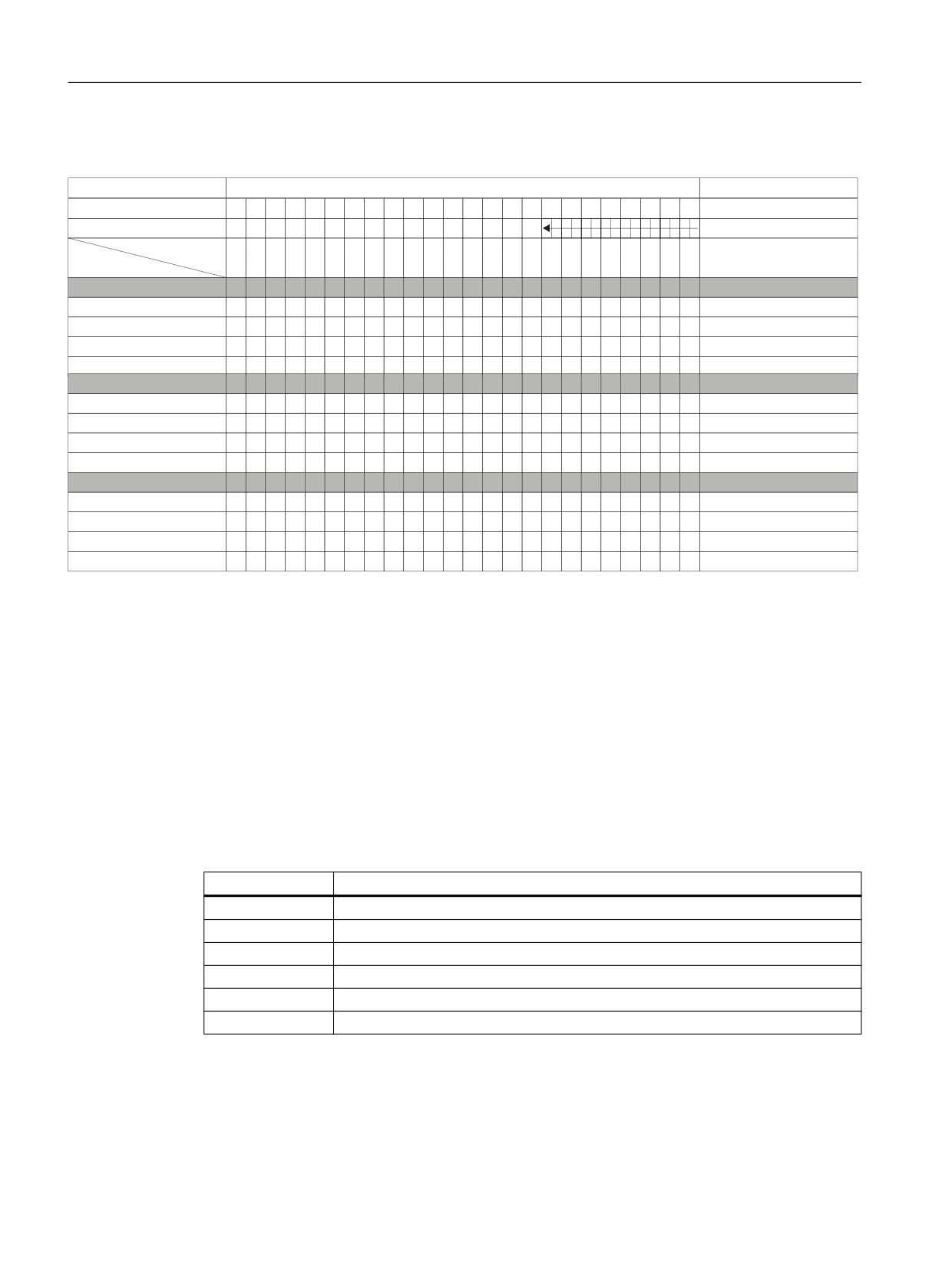
Interrupt assignment (PCI-IRQ)
,54 1XPEHU
&RPPHQWV
$&3, ,54
,54
+RVW 3&, ,54 /LQH
$
%
&
'
(
)
*
+
)XQFWLRQ
6ORW
3&,
3&, ,17 3LQ $
=
<
3&, ,17 3LQ %
=
<
3&, ,17 3LQ &
=
<
3&, ,17 3LQ '
=
<
6ORW
3&,
3&, ,17 3LQ $
=
<
3&, ,17 3LQ %
=
<
3&, ,17 3LQ &
=
<
3&, ,17 3LQ '
=
<
6ORW
3&,H[SUHVV
3&, ,17 3LQ $
=
<
3&, ,17 3LQ %
<
3&, ,17 3LQ &
=
<
3&, ,17 3LQ '
<
1)
In the APCI mode, host PCI-IRQ A to H is permanently assigned to IRQ 16 to 23. In the PIC mode, host PCI-IRQ A to
H is automatically assigned to IRQ 0 to 15 from the BIOS. A certain assignment cannot be forced.
Y Interrupt in the APIC mode (e.g. Windows XP)
Z BIOS default interrupt in the PIC mode (e.g. DOS)
Image 15-9 Interrupt assignment of the slot connectors on the bus PCB
Exclusive PCI hardware interrupt
Applications, which have high requirements regarding the interrupt performance, need a fast
interrupt response time of the hardware. The PCI hardware interrupt should only be occupied
by a resource in order that a fast hardware response time is possible.
Exclusive interrupt in the APIC mode
IRQ assignments for Windows systems, (APIC mode)
Ethernet 1
16 1) 2)
Ethernet 2
17 1)
Profibus/MPI
19 1)
PCI slot 1
20 1)
PCI slot 2
21 1)
PCI Express slot
16 1) 3)
1) Precondition: The modules in the PCI slots each require only one interrupt
2) Precondition: VGA and PCIexpress do not require an interrupt
3) Precondition: VGA does not require an interrupt - and Ethernet1 is disabled
Operator panels
230
Manual, 03/2016, 6FC5397-1AP40-5BA3
PCU 50.5
15.4 Mounting
Exclusive interrupts in the PIC mode
The system BIOS is set when delivered so that for the system start, the interrupts are
automatically assigned to the slots.
Depending on the system expansion, it is therefore possible that the same interrupt is assigned
to several slots. In this case this is called interrupt sharing. No exclusive interrupts are available
in the PIC mode. You must disable system resources in order to obtain exclusive interrupts. It
cannot be predicted which PIC interrupts will be assigned by BIOS at the next start.
15.4
Mounting
15.4.1
Preparation for mounting
Mounting of the PCU 50.5 depends on how it is going to be used. A distinction is made between
the following types of mounting:
1. Standard mounting: Operator panel on the machine
- for assembly of PCU and operator panel front
2. Flat mounting: In the control cabinet
- for PCU flat on the control cabinet rear wall
3. Book mounting: In the control cabinet
- for PCU at an angle of 90° to the control cabinet rear wall
You require a suitable set of mounting brackets for each mounting method. You can find the
corresponding article number in Section "Accessories".
Note
First, screw the appropriate mounting brackets onto the PCU before you mount the PCU on
an operator panel front.
NOTICE
Damage to the mainboard
For installing the mounting brackets for the upright installation, use only M4x10 screws. For
all remaining mounting brackets, use M3x8 and M4x8, (provided).
The mainboard will be damaged if you
screw in the M3x8 and M4x8 screws without mounting brackets,
- or if you use other 8 mm screws (without a flat washer or tension ring) or
- longer screws,
- use the M4x10 screws for mounting the brackets on the PCU 50 (previous model).
Operator panels
Manual, 03/2016, 6FC5397-1AP40-5BA3
231
PCU 50.5
15.4 Mounting
WARNING
Securing the PCU on the wall or to the ceiling
Ensure that the wall or ceiling can support four times the total weight of the PCU (including
mounting brackets and additional expansion modules).
The total weight of the PCU is max. 7 kg.
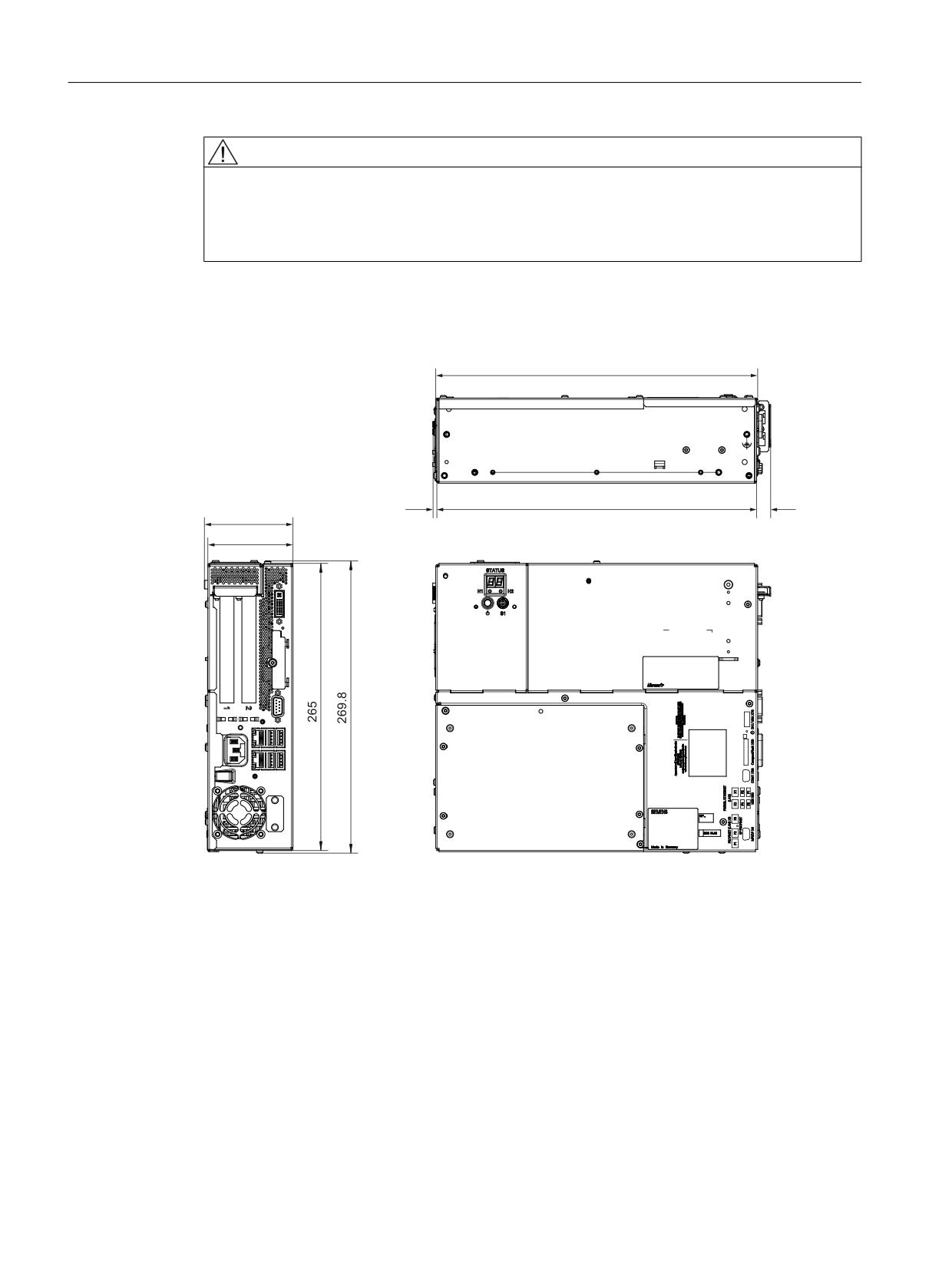
Dimension drawings for mounting
Image 15-10 PCU 50.5 dimension drawing for mounting without ETH strain relief
Operator panels
232
Manual, 03/2016, 6FC5397-1AP40-5BA3
PCU 50.5
15.4 Mounting
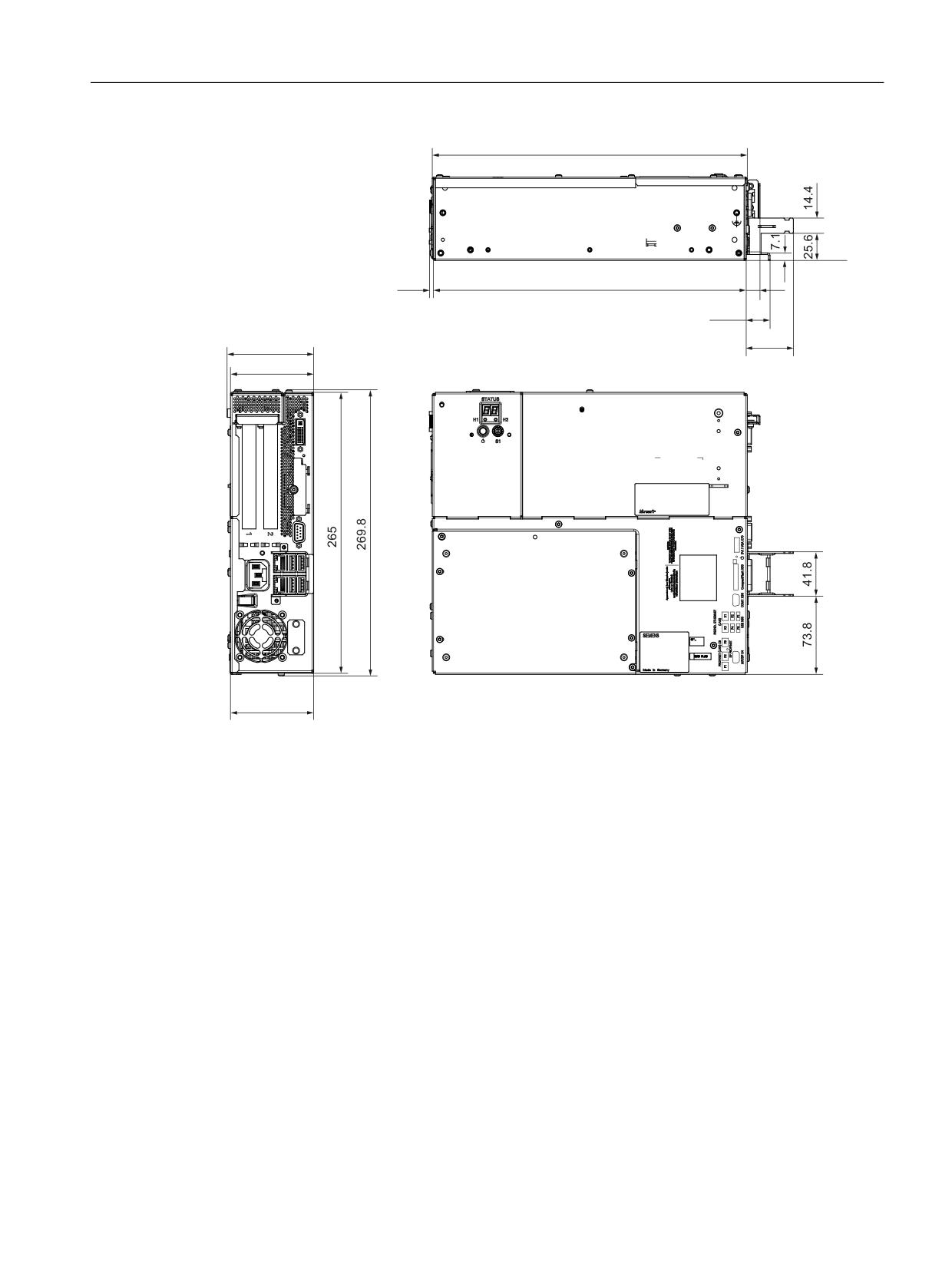
Image 15-11 PCU 50.5 dimension drawing for mounting with ETH strain relief
Operator panels
Manual, 03/2016, 6FC5397-1AP40-5BA3
233
PCU 50.5
15.4 Mounting
15.4.2
Assembly of PCU and operator panel front (standard mounting)
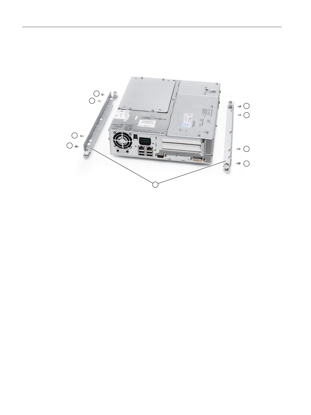
The figures shows the PCU and mounting bracket for standard mounting correctly aligned
before screwing together (tightening torque M3: 0.8 Nm, tightening torque M4: 1.8 Nm).
① M4x8 countersunk screw with high tension ring and washer
② M3x8 countersunk screw with high tension ring and washer
③ Mounting bracket
Image 15-12 PCU 50.5 with mounting brackets (standard mounting)
Mounting the PCU 50.5 with an operator panel front depends on the size of the operator panel
front:
● When mounting a PCU 50.5 and operator panel fronts with screen diagonals ≤ 15 inch,
refer to Chapter: “OP 012,” section: "Mounting" → "Assembling OP 012 and PCU."
● Mounting a PCU 50.5 with an operator panel front OP 019 is described in Chapter: “OP
019,” Section: "Mounting" → "Assembling OP 019 and PCU 50.5".
15.4.3
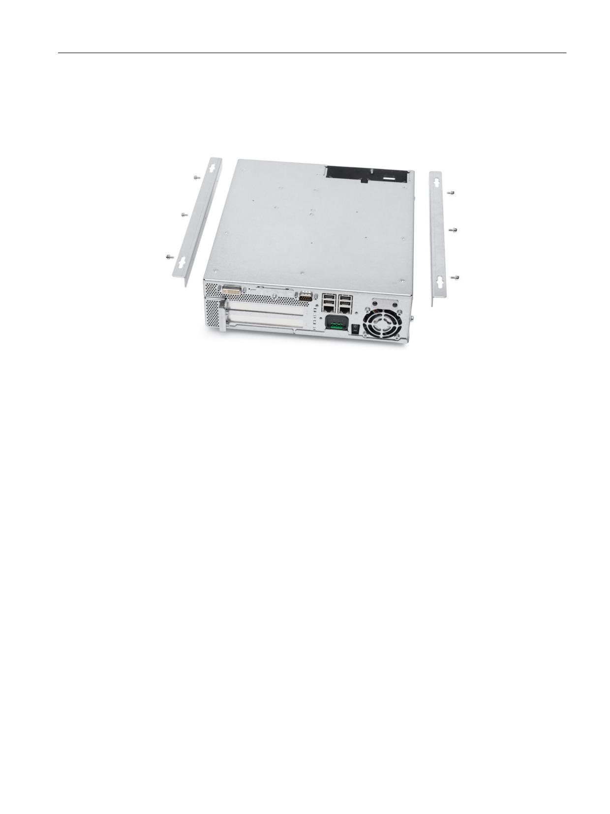
Flat mounting
Use the 'flat' mounting bracket (see section: "Accessories" → "Overview") to mount the PCU
flat onto the side panel of the control cabinet.
Operator panels
234
Manual, 03/2016, 6FC5397-1AP40-5BA3
PCU 50.5
15.4 Mounting
Procedure
1. Mount the two brackets on the right and left of the PCU one after the other.
2. Mount the PCU on the side panel of the control cabinet in accordance with the mounting
instructions (see Section: "Mounting instructions").
Image 15-13 PCU 50.5 with bracket for flat mounting
Operator panels
Manual, 03/2016, 6FC5397-1AP40-5BA3
235
PCU 50.5
15.4 Mounting
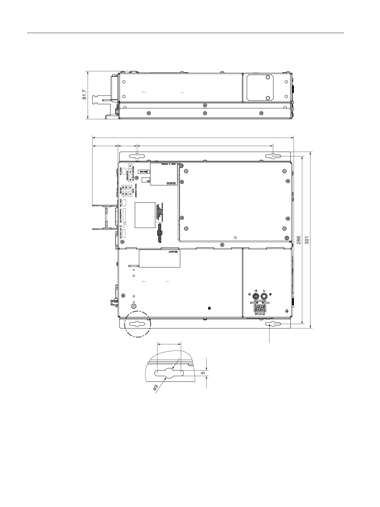
Dimension drawing
$
6ORWV IRU 0 PRXQWLQJ VFUHZV
WLJKWHQLQJ WRUTXH
1P
$
Image 15-14 Dimension drawing, PCU 50.5 mounted flat
15.4.4
Upright mounting
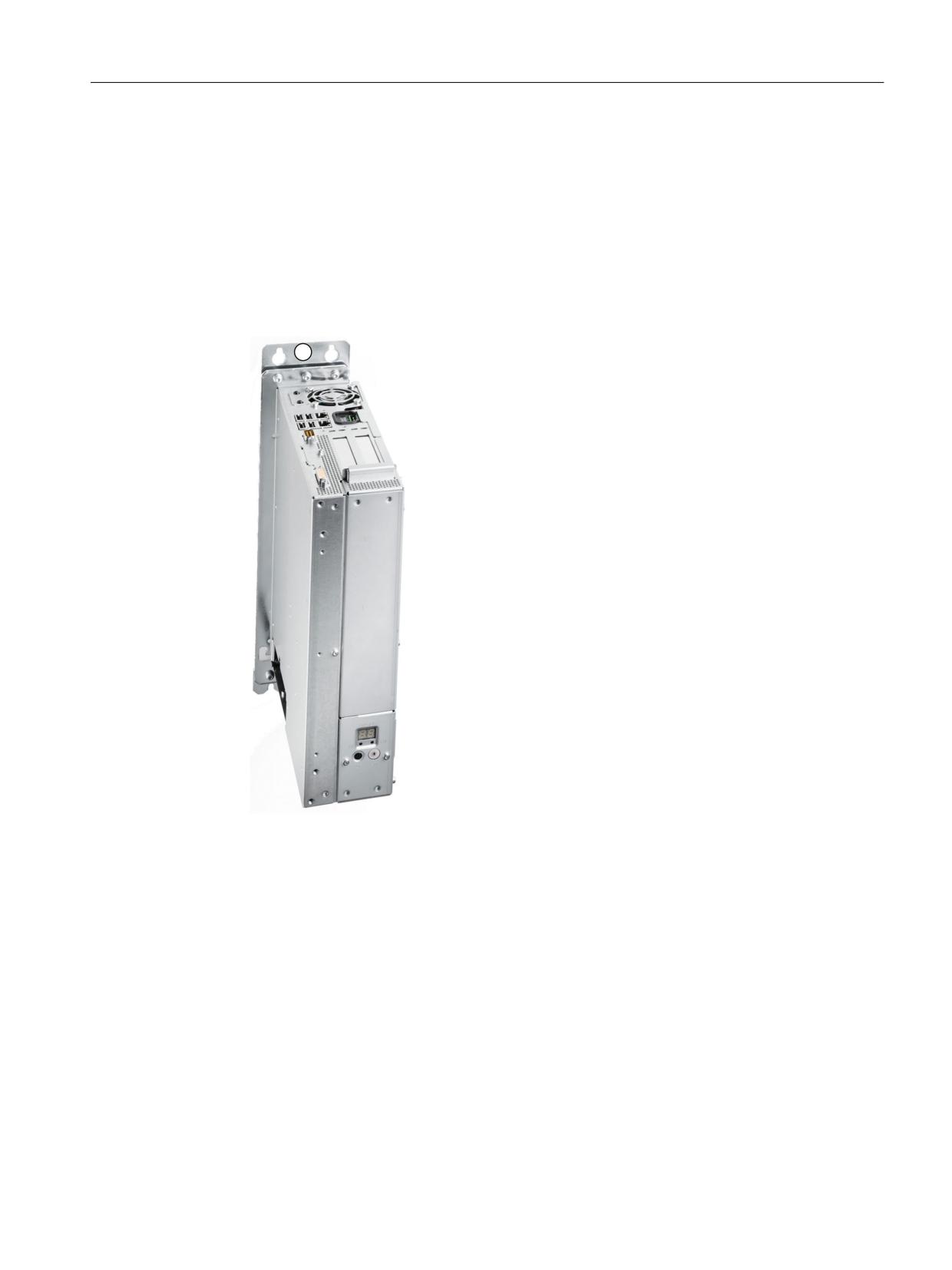
Use the 'upright' mounting bracket (see Section: "Accessories" → "Overview"), to mount the
PCU in the control cabinet.
Operator panels
236
Manual, 03/2016, 6FC5397-1AP40-5BA3
PCU 50.5
15.4 Mounting
Two mounting positions are possible:
● Power switch at the top
● Power switch at the bottom
Procedure
1. Mount the rear panel bracket on the right side of the PCU (see the diagram).
2. Mount the PCU at a 90° angle in the control cabinet.
① 'Upright' mounting bracket
Image 15-15 PCU 50.5 with mounting bracket for upright mounting (power switch at the top)
Operator panels
Manual, 03/2016, 6FC5397-1AP40-5BA3
237
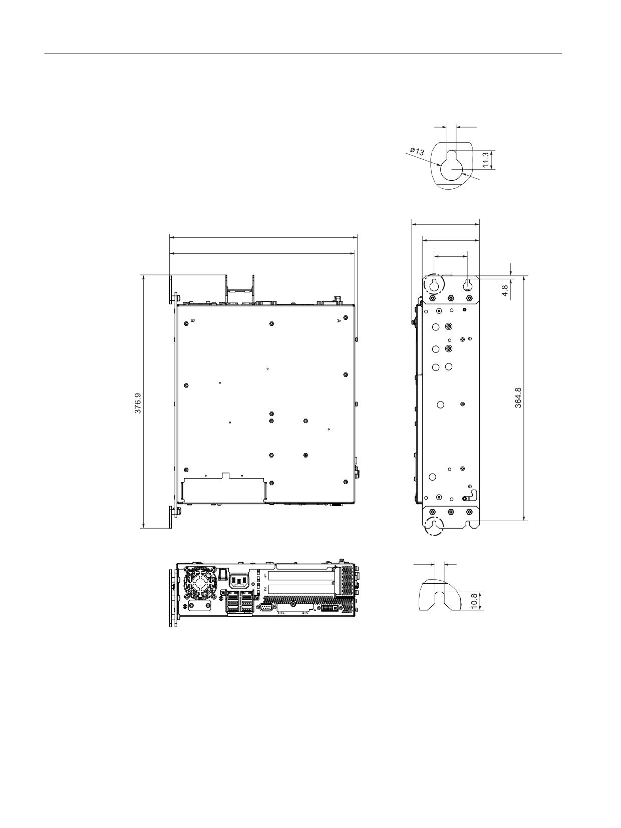
PCU 50.5
15.4 Mounting
Dimension drawing
$
$ % 6ORWV IRU PRXQWLQJ VFUHZV
0
WLJKWHQLQJ WRUTXH
1P RU
0
WLJKWHQLQJ WRUTXH 1P
$
%
%
Image 15-16 Dimension drawing for the upright mounting of the PCU 50.5 (power switch at the top)
Operator panels
238
Manual, 03/2016, 6FC5397-1AP40-5BA3
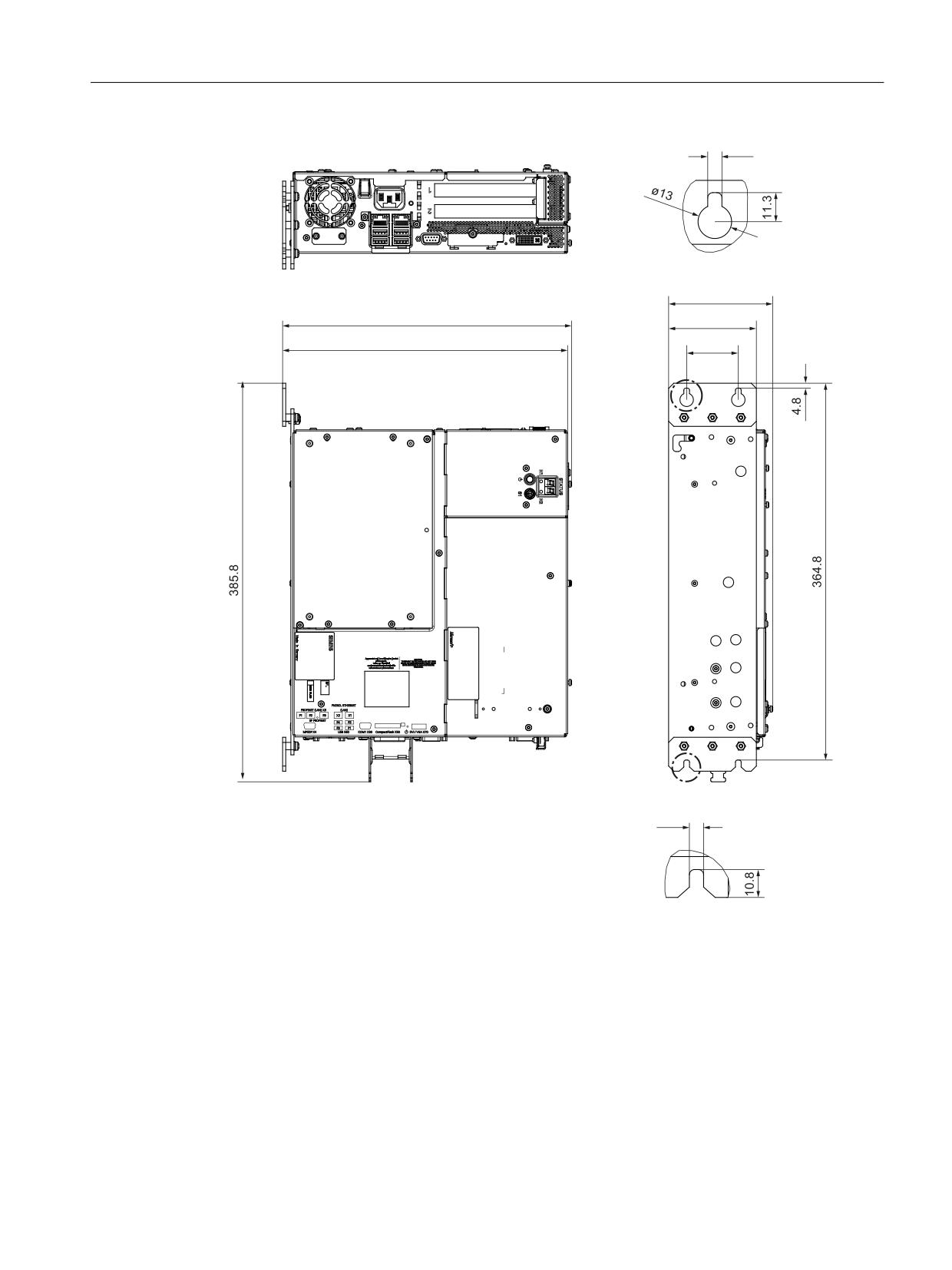
PCU 50.5
15.4 Mounting
$
$
%
$ % 6ORWV IRU PRXQWLQJ VFUHZV
%
0
WLJKWHQLQJ WRUTXH
1P RU
0
WLJKWHQLQJ WRUTXH 1P
Image 15-17 Dimension drawing for the upright mounting of the PCU 50.5 (power switch at the bottom)
15.4.5
Notes on installation
Observe the following during installation:
● Avoid extreme environmental conditions as far as possible.
Protect the PCU from severe vibrations, jolts, dust, humidity and heat.
● An external fire protection housing is required.
● Do not expose the PCU directly to the sun's rays.
Operator panels
Manual, 03/2016, 6FC5397-1AP40-5BA3
239
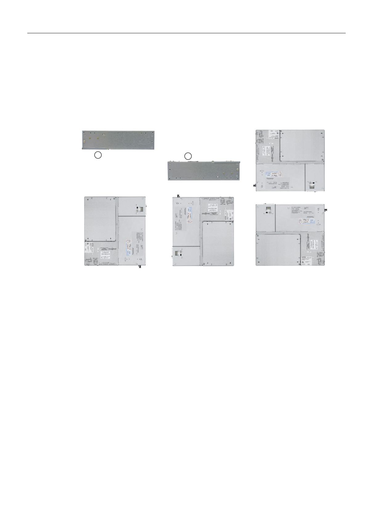
PCU 50.5
15.4 Mounting
● Install the device in such a way that no danger (e.g. by falling down) may result.
● Ventilation clearances:
- Both fan sides: 50 mm each.
- On top, on the bottom, on the rear side: 10 mm (see Fig.)
● Make sure that the vent slots are not covered.
Permissible mounting positions of the PCU 50.5 acc. to UL508
① Position of hard disk
Inclined position
On the basis of the standard mounting positions shown above (checked with a variance of ±
5°), an inclined position of up to ± 20° is permitted if sufficient ventilation is still ensured.
15.4.6
Connecting Ethernet/USB strain relief
The Ethernet/USB strain relief supplied in the product package is used to prevent accidental
removal of the Ethernet cable and Industrial Ethernet FastConnect connector from the device.
You need two cable ties to use the strain relief. In addition to the Ethernet cables, you can also
use this strain relief to protect the four USB cables from inadvertent removal.
Preconditions
● Take the strain relief ①, the cable tie ② and the two screws (M3) from the accessories
pack provided.
● To secure the strain relief, you will need a TORX T10 screwdriver.
Operator panels
240
Manual, 03/2016, 6FC5397-1AP40-5BA3
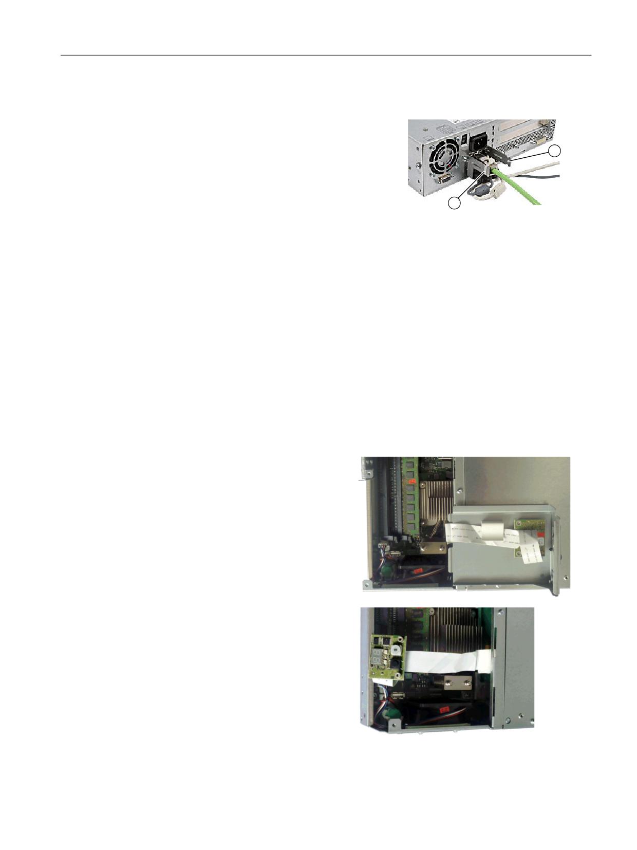
PCU 50.5
15.4 Mounting
Procedure
1. Fasten the Ethernet/USB strain relief ① to the de-
vice enclosure using two oval-head screws (M3
thread).
2. Connect the network/USB cable and attach it to the
strain relief using cable ties ②.
15.4.7
Relocating the service module
When delivered, the service module is integrated in the cover, see the top view of the PCU 50.5
in ChapterDescription (Page 213). For upright mounting in the control cabinet, due to the
serviceability, the service module should be relocated onto the side panel next to the equipment
fan.
Preparations
1. Disconnect the device from the line supply.
2. Remove the enclosure cover of the motherboard.
Procedure
1. Loosen the screws for the enclosure cov-
er of the service module and swing out
the housing cover to the rear with the still
attached service module.
2. Release the fixing screws of the service
module and place it down in the direction
of the new mounting location.
Operator panels
Manual, 03/2016, 6FC5397-1AP40-5BA3
241
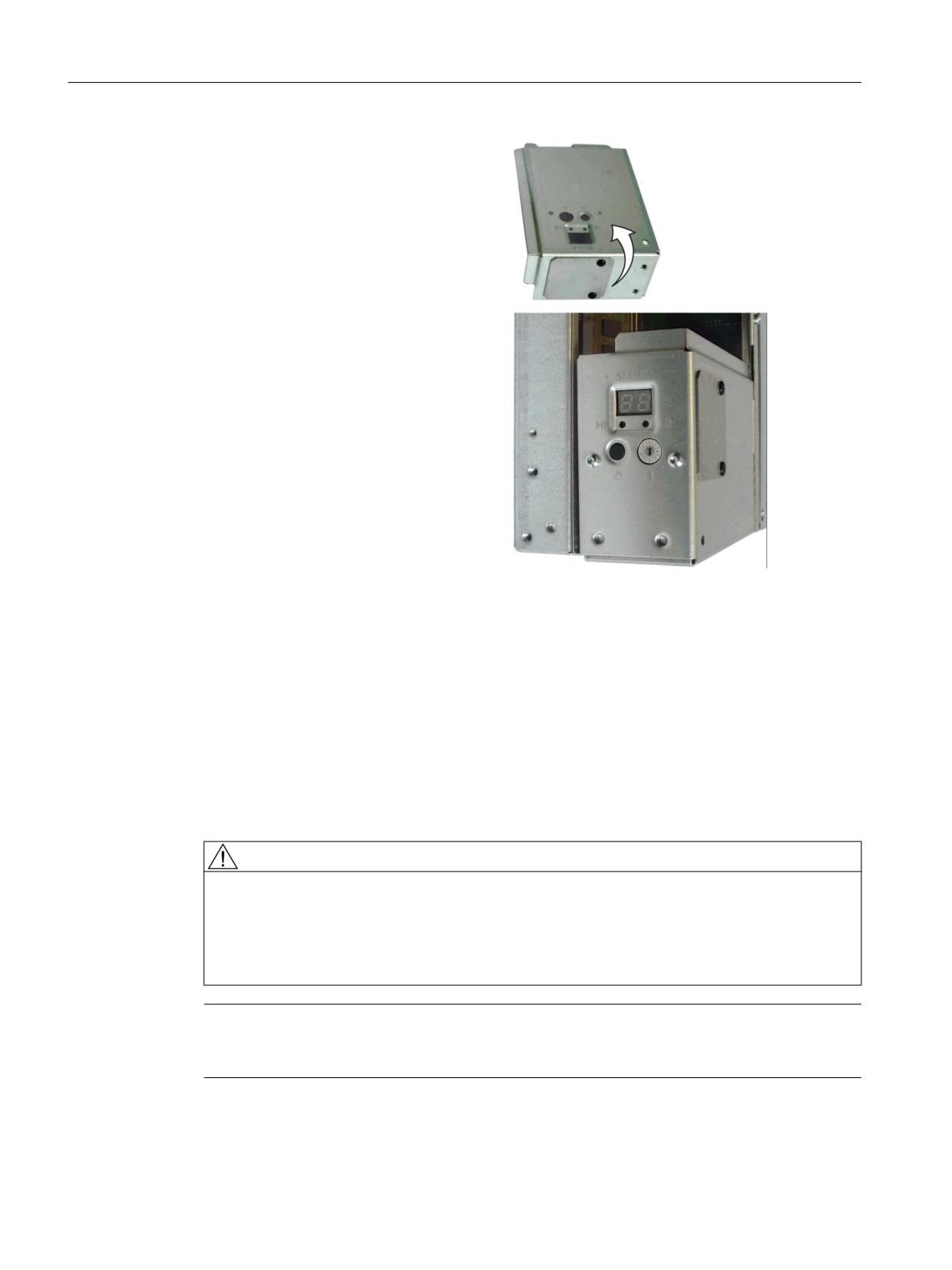
PCU 50.5
15.5 Connecting
3. Remove the cover for the service mod-
ule and mount it at the new location.
4. Now mount the service module at the
new location. Before closing the cover of
the housing, ensure that the ribbon cable
is correctly folded.
15.5
Connecting
15.5.1
Power supply
The PCU 50.5 is supplied with 24 V DC.
Preconditions
WARNING
Impermissible cable cross-sections can damage the PCU
The cable cross-section must be adapted to the short-circuit current of the 24 V DC power
source so that no damage is caused by the cables if a short-circuit occurs.
Only cables with a cross-section of at least 1.3 mm2 (AWG16) and maximum 3.3 mm2
(AWG12) may be connected.
Note
The 24 V DC power source must be adapted to the input data of the PCU (see Calculating the
power (Page 264)).
Ensure that the PCU's On/Off switch is in the '0' (Off) position to prevent unintentional startup
of the device when connecting it to the power supply.
Operator panels
242
Manual, 03/2016, 6FC5397-1AP40-5BA3
PCU 50.5
15.5 Connecting
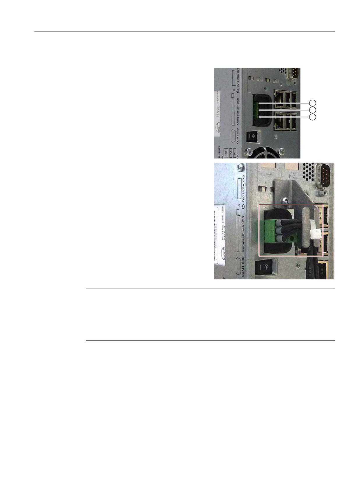
Procedure
1. Switch off the 24 V DC power source.
2. Connect the DC connector
① 24 V DC
② Ground
③ Protective conductor
3. Fasten the cable with the supplied line con-
nector interlock, if necessary.
Note
Reverse polarity protection
The DC power supply (24 V; -15% / +20%) has a mechanism to protect against reverse polarity.
The unit is not damaged if the cables and ground are connected, interchanged. The unit does
not switch on. After the power supply has been connected correctly, the unit will again be ready
to operate.
15.5.2
Equipotential
A low-impedance ground connection ensures that interference signals generated by external
power supply cables, signal cables or cables to the I/O modules are safely discharged to
ground.
The equipotential bonding terminal ① on the device (large surface, large-area contact) must
be connected with the central grounding point of the cabinet or plant in which the PCU is to
Operator panels
Manual, 03/2016, 6FC5397-1AP40-5BA3
243

PCU 50.5
15.5 Connecting
be installed.
The minimum cross section must not fall below 5 mm2.
Image 15-18 PCU 50.5 equipotential bonding connection
15.5.3
I/O devices
Note
When connecting up I/O devices, check that they are suitable for industrial applications acc.
to EN 61000-6-2:2001.
Operator panel front
If you are using the PCU together with an operator front panel, before switching on the PCU
first connect up the operator front panel.
Note
Simultaneous operation of the operator panel and monitor is no longer activated as standard
under Windows XP. If required, activate in the Windows user interface.
DVI / VGA monitor
Only switch on the PCU once you have connected the external monitor.
Otherwise, this interface is automatically deactivated.
CF card
Only switch on the PCU once you have plugged in the CompactFlash card.
The CompactFlash interface is not capable of acting as a hot-plug. Never plug-in or pull a card
while the PCU is operating.
Operator panels
244
Manual, 03/2016, 6FC5397-1AP40-5BA3
PCU 50.5
15.6 Commissioning
Units based on USB
You can connect or disconnect devices based on USB (USB 1.1 Full Speed or 2.0 Hi-Speed)
during PCU operation if this is supported by the operating system (e.g. Windows XP).
Note
If you are using commercially available USB devices, the interference immunity of the entire
system can be reduced. The end user takes responsibility for the use of such devices.
Information on which connection cable is required and how to adapt and set the interface can
be found in the User's Manual for your I/O device.
15.6
Commissioning
15.6.1
BIOS
15.6.1.1
BIOS powering up
Once you have switched the PCU on, the preinstalled system powers up automatically. During
powering up, the parameters saved in the BIOS setup take effect.
If necessary, you can reactivate the factory-preset parameters (default values) at anytime
during the setup using the <F2> key.
1. Press the <F9> (default load) key to do this.
2. Store the settings by pressing the <F10> button (save settings).
Once powering up is complete, the start screen is displayed (see IM8: Commissioning the PCU
base software).
Checking the boot sequence
If you want to check or change the boot sequence:
1. Switch on the PCU.
2. By pressing <F12>, the boot menu and the boot options are displayed. Booting can also
be optionally started from other devices (e.g. USB-FlashDrive).
Note
When setting up the boot operation, observe the service switch position, see SectionService
module (Page 217).
3. Select the desired boot device and press the enter key.
Operator panels
Manual, 03/2016, 6FC5397-1AP40-5BA3
245
PCU 50.5
15.6 Commissioning
Booting using the USB FlashDrive
If you connect an external USB device or start from a boot-capable USB FlashDrive for
servicing purposes, you have to manually call up the USB device from setup. You have three
options:
USB device automatically boots
1. Set the service switch to position "E".
2. After a restart, booting is realized automatically from the USB device.
3. For normal operation, set back to "0".
USB device is entered in the boot list (normal operation)
1. Switch on the PCU.
2. When requested, press the <F12> key.
3. Select the desired device from the boot list and confirm.
USB device is not entered in boot list
1. Switch on the PCU.
2. Press the <F2> key.
3. Go to the menu bar for <Boot>.
4. Use the '↓' button to reach the "Legacy Boot Type Order" entry and select the USB device
you want to enter in the boot list.
5. If you want to change the sequence of devices within the boot list, select the corresponding
device and press the '+' key to move further up the list or the '-' key to move further down
the list.
6. Save the settings by pressing the <F10> key and confirm the changes with "Yes".
7. Then restart the PCU.
PCU doesn't boot up
If the PCU no longer boots up as a result of incorrect settings in the BIOS:
1. Take the battery out (see section: "Spare parts" → "Replacement" → "Battery").
2. Bridge the pins of the PCU's battery connector for approx. 10 seconds with a conductive
object.
3. Then wait approx. 1 minute.
4. Put the battery back in.
All the BIOS settings (including time and date) are thereby reset.
5. You can set the time and date using the <F2> key.
6. Use the <F9> button to load the default values and the <F10> button to save these.
Operator panels
246
Manual, 03/2016, 6FC5397-1AP40-5BA3
PCU 50.5
15.6 Commissioning
15.6.1.2
Changing the BIOS settings
If additional components (e.g. an external USB diskette drive) are attached or removed, you
may need to change the BIOS settings (see Section: "BIOS start up" → "Booting using the USB
FlashDrive").
NOTICE
Incorrect BIOS settings can prevent the system startup
Only change the BIOS settings if you are fully aware of the consequences of doing so!
Incorrect settings may result in the entire system (including the operating system) no longer
starting (see Section: "BIOS start up" → "PCU not booting up").
Changing the BIOS settings using the standard keyboard
Creating your own user profile
Use the "User" profile in the setup menu if you need your own settings in the BIOS and want
to permanently save these settings (also used after changing the battery).
1. Switch on the PCU and wait a few seconds.
2. Once you have been prompted to switch to the BIOS setup, press the <F2> button. The
BIOS Setup menu will appear.
3. Select "User" under "Exit" → "Profile".
4. Make your specific settings in the other menu items.
5. Save the new settings permanently using the <F10> button by confirming the dialog with
"Yes".
6. Your specific settings will be available once the machine has been restarted.
Calling up your own user profile
As soon as you select the "User" selection from the "Exit" → "Profile" setup setting and save
with the <F10> button and "Yes" the values saved originally appear after a reboot, provided
that you do not change any data (with the exception of the date and time).
Changing data (with the exception of the date and time) is the same as creating a new user
profile (see "Creating your own user profile").
Changing the BIOS settings via an operator panel front
1. Switch on the PCU and wait a few seconds.
2. Once you have been prompted to switch to the BIOS setup, press the <F2> button. The
BIOS Setup menu will appear.
3. Use the cursor keys for navigating in the menu to the desired selection field (e.g. "Disk A:").
4. Change the setting using the <+> key (press <SHIFT> and <X> at the same time) or the
<-> key on in the numeric keypad.
Operator panels
Manual, 03/2016, 6FC5397-1AP40-5BA3
247