SINUMERIK 840D sl Hardware. Manual (2011-2020) - page 7
Handheld Terminal HT 2
1.3 Connecting
6723
6723
+7
35(6(17
35(6(17
&RQQHFWLQJ FDEOH
9
7HUPLQDO VWULS
SLQ
6723
6723
6723
9
9
9
6723
9
&75/
35(6(17
9
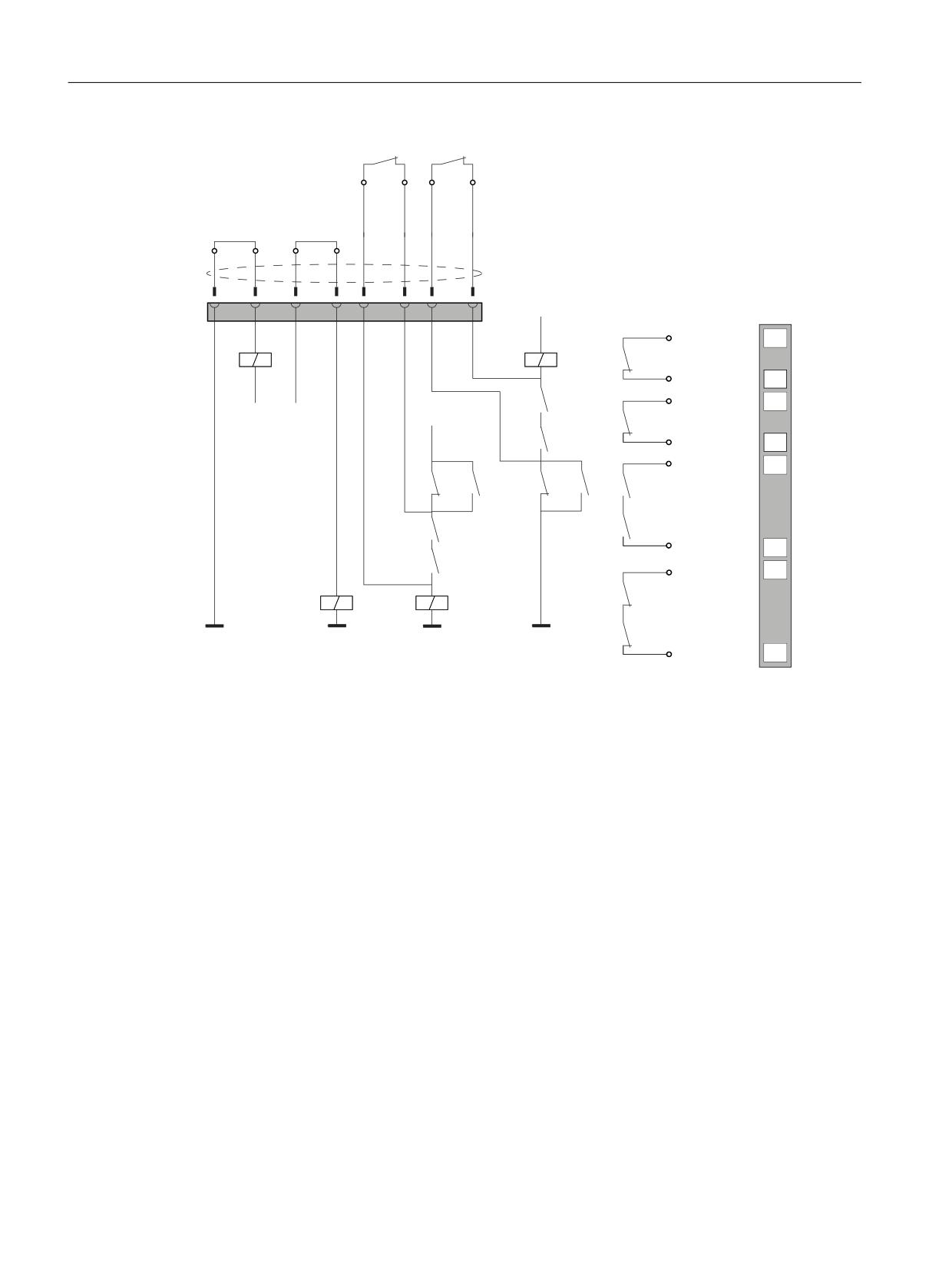
Image 1-10 Circuit example 2: HT 2 connected, power supply switched on and emergency stop inactive
Handheld units
22
Manual, 03/2016, 6FC5397-1AP40-5BA3
Handheld Terminal HT 2
1.3 Connecting
6723
6723
+7
35(6(17
35(6(17
&RQQHFWLQJ FDEOH
9
7HUPLQDO VWULS
SLQ
6723
6723
6723
9
9
9
6723
9
&75/
35(6(17
9
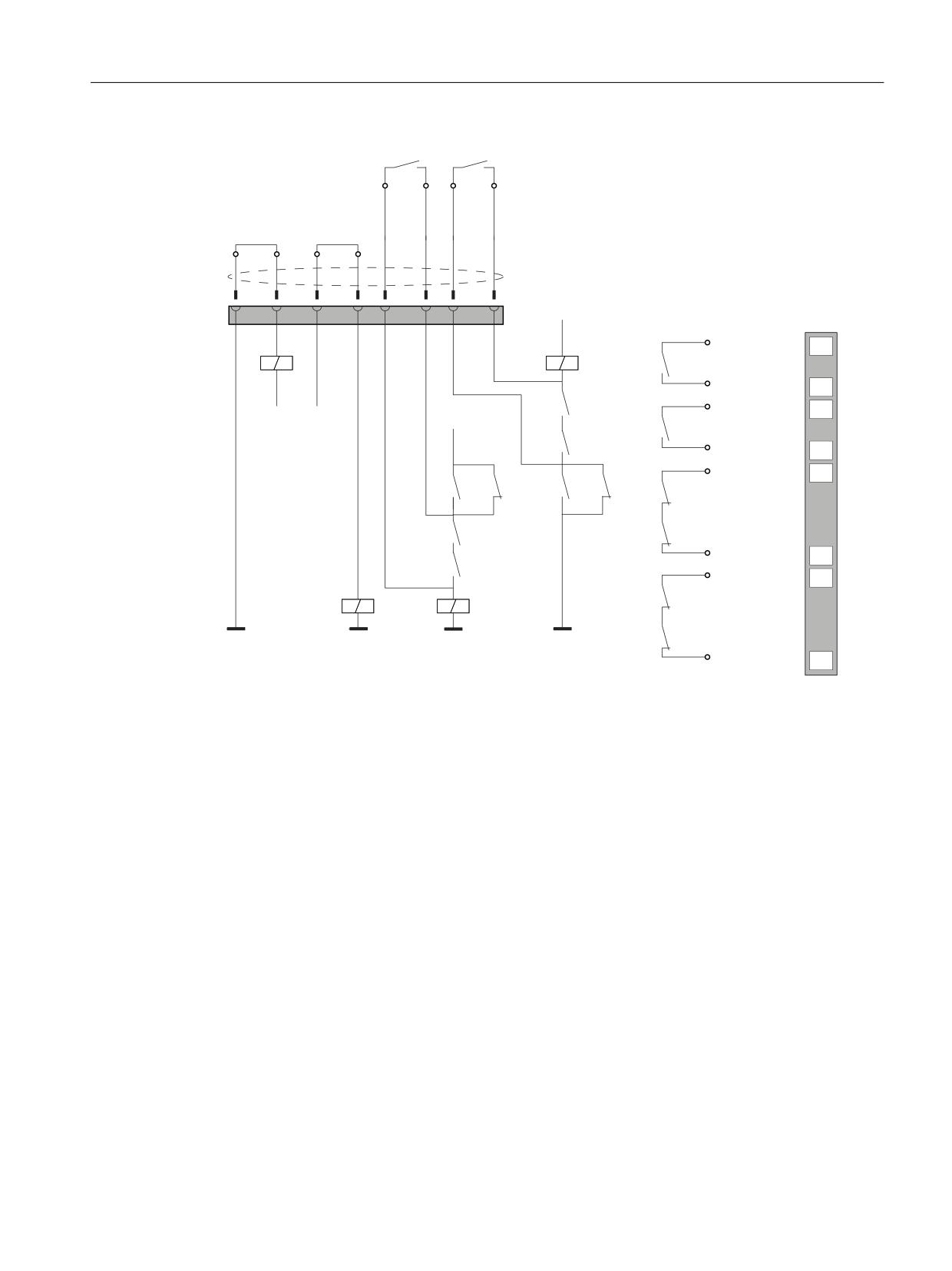
Image 1-11 Circuit example 3: HT 2 connected, power supply switched on and emergency stop active
Handheld units
Manual, 03/2016, 6FC5397-1AP40-5BA3
23
Handheld Terminal HT 2
1.3 Connecting
6723
6723
+7
35(6(17
35(6(17
&RQQHFWLQJ FDEOH
9
7HUPLQDO VWULS
SLQ
6723
6723
6723
9
9
9
6723
9
&75/
35(6(17
9
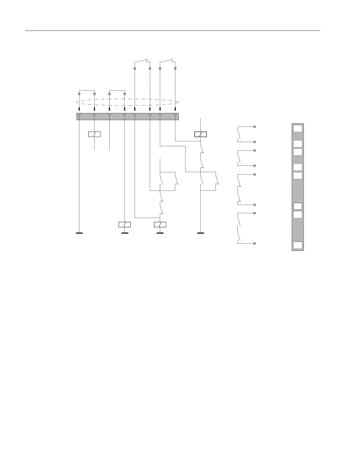
Image 1-12 Circuit example 4: Power supply switched off
The "CTRL32 / STOP button pressed" signal is not present at the Basic connection box. The
signal has no error detection facility and must, therefore, not be used for safety-critical
applications.
Note the following when connecting the "Present31 HT 2 / HT 8 connected" signal:
● Connect Pin 7 of the connection box to the digital input of the control
● Basic connection box: Pin 8 of the connection box remains not assigned
● Plus connection box: +24 V must be supplied at Pin 8
Handheld units
24
Manual, 03/2016, 6FC5397-1AP40-5BA3
Handheld Terminal HT 2
1.3 Connecting
1.3.2.4
PN Basic terminal box
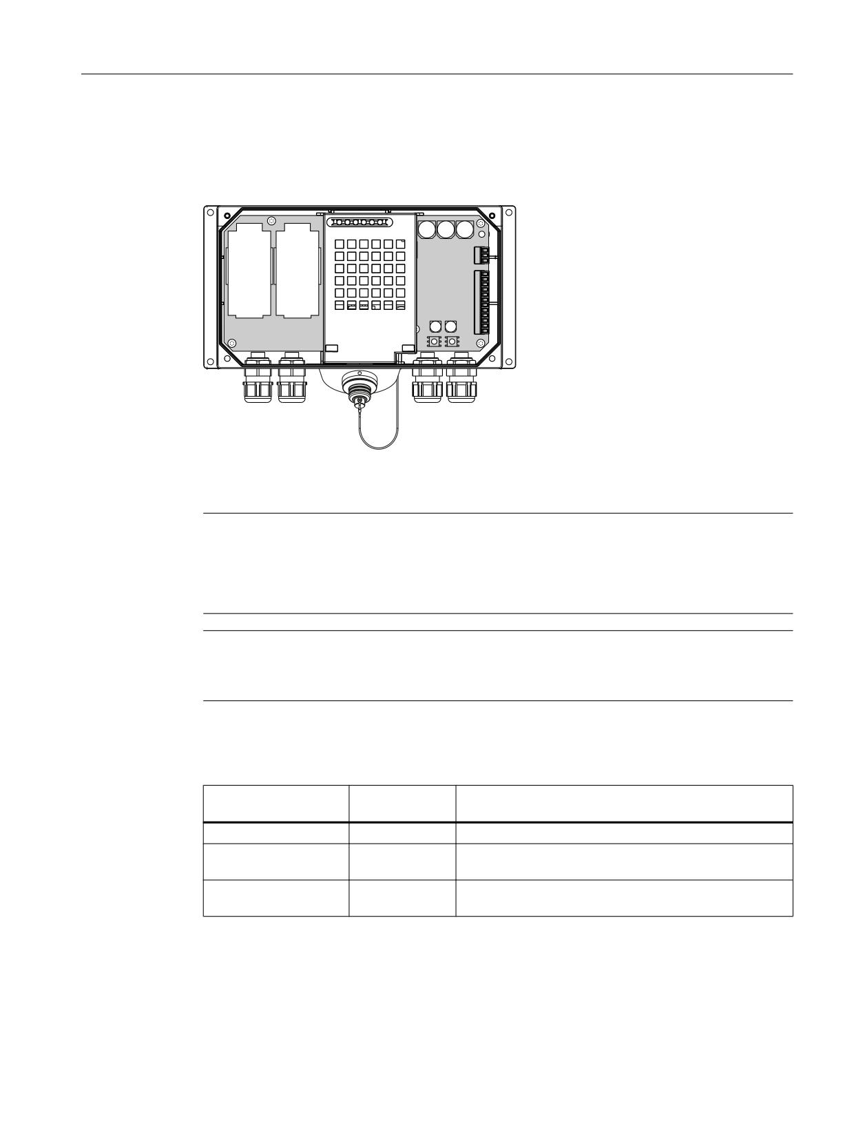
In contrast to the PN Plus terminal box, the "Stop loop through" function is not implemented
on the PN Basic terminal box. Relays are so not required.
Image 1-13 PN Basic terminal box
Note
The emergency stop circuit is controlled via the emergency stop button when the HT 2 is
connected. If the connecting cable of the HT 2 is disconnected from the PN Basic terminal
box, the emergency stop circuit is interrupted. This leads to a safe machine stop or an
emergency stop of the system to be monitored.
Note
The "CTRL32 / STOP button pressed" signal is not present at the Basic connection box.
The signal has no error detection facility and must not be used for safety-critical applications.
Switching states of the emergency stop circuit
HT 2
Emergency
Switching status, emergency stop circuit
Stop button
Connected
Not pressed
Emergency stop circuit in the terminal box remains closed.
Connected
Pressed
The emergency stop circuit in the terminal box is open.
The system to be monitored is stopped.
Not connected
-
The emergency stop circuit in the terminal box is open.
The system to be monitored is stopped.
Handheld units
Manual, 03/2016, 6FC5397-1AP40-5BA3
25
Handheld Terminal HT 2
1.3 Connecting
WARNING
Danger of death resulting from the premature emergency stop unlocking
If you have shut down the system to be monitored, you can only release the emergency stop
button or put the system to be monitored back into operation if the condition that triggered
the emergency stop function has been corrected and a safe restart is carried out.
Handheld units
26
Manual, 03/2016, 6FC5397-1AP40-5BA3
Handheld Terminal HT 2
1.3 Connecting
1.3.3
Connection module Basic PN
1.3.3.1
Features
The connection module Basic PN was specially developed for installation in the control cabinet.
The terminating connector protrudes through the panel of the control cabinet so that the HT 2
can be connected from the outside.
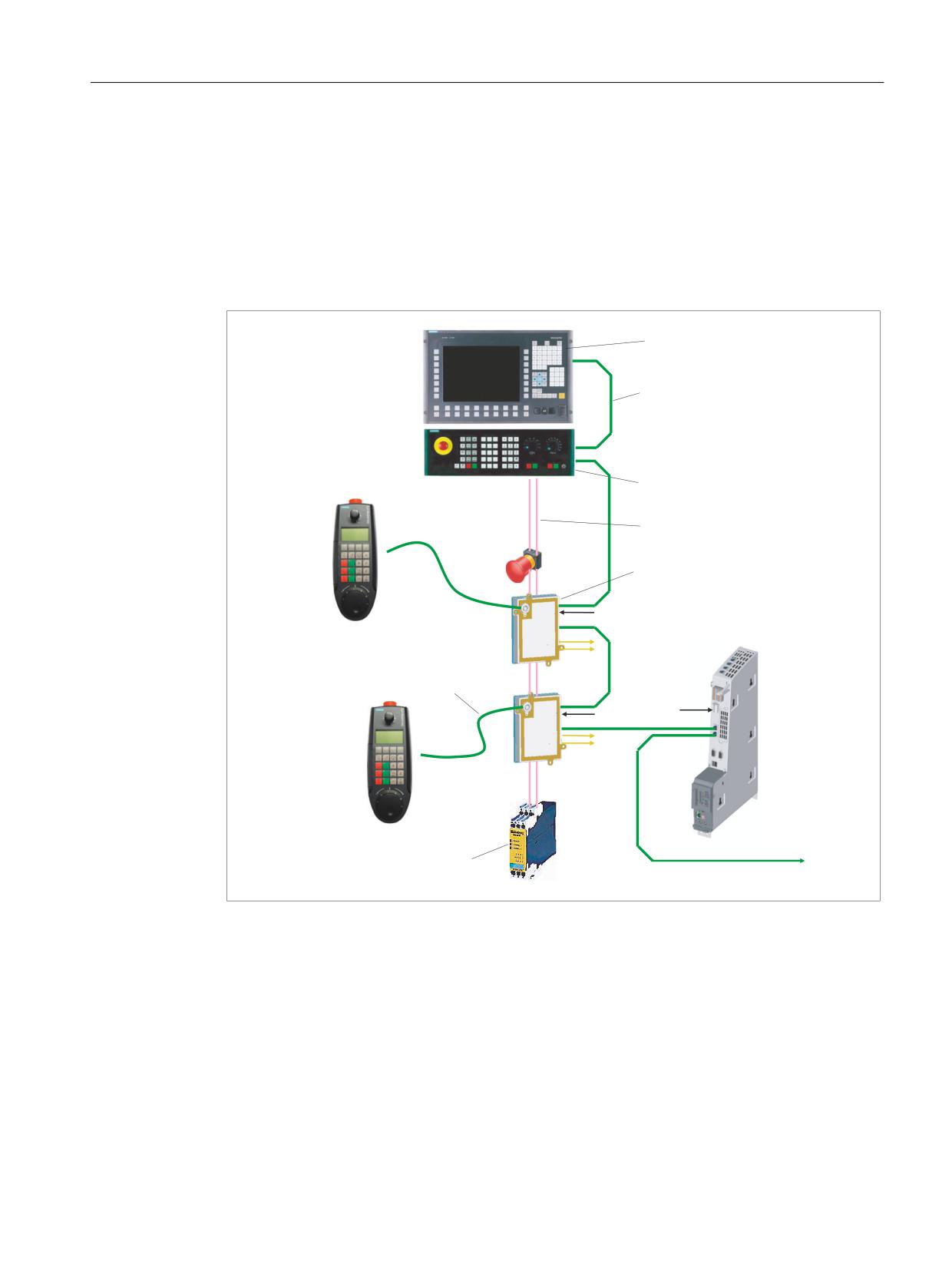
2SHUDWRU 3DQHO
+0,
6\VWHP QHWZRUN
0DFKLQH FRQWURO SDQHO
+7
(PHUJHQF\ 6WRS FLUFXLWV
&RQQHFWLRQ PRGXOH 31
3
&RPEL FDEOH
3
3
+7
&RQWURO
6WDWXV VLJQDOV
1&8 [
(PHUJ 6WRS
3DQHO SUHVHQW
6DIHW\
&RPELQDWLRQ
)DFWRU\ QHWZRUN
7.
Image 1-14 System configuration (example)
The connection module Basic PN is not hot plug-capable.
The HT 2 can either be connected to the NCU or to the PCU as thin client.
1.3.3.2
interfaces
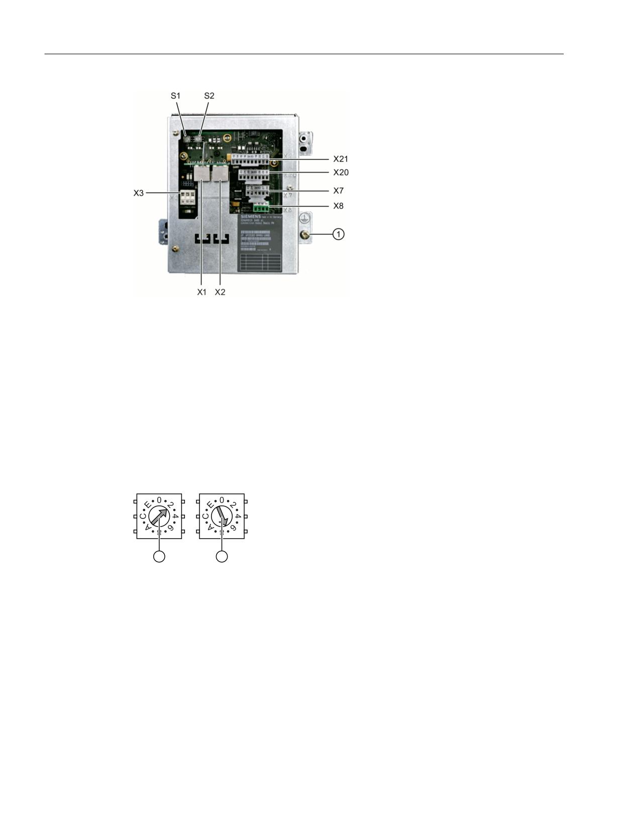
The HT 2 is connected to the connection module Basic PN via a round connector.
The interfaces of the connection module are located at the rear:
Handheld units
Manual, 03/2016, 6FC5397-1AP40-5BA3
27
Handheld Terminal HT 2
1.3 Connecting
① Grounding screw M5 for potential equalization connection
Image 1-15 Rear of the Basic PN connection module
Setting the box ID
You can use rotary coding switches S1 and S2 to set a unique ID on any connection module
for station identification purposes.
Use a screwdriver to set the IDs.
The setting is entered in hexadecimal format. Values in the decimal format between 0 and 255
can be entered.
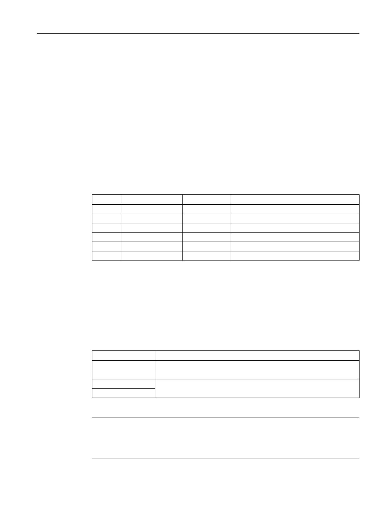
By way of an example, the figure below illustrates address 27H, which corresponds to decimal
address 39.
① Rotary coding switch for higher-order bits (S1)
② Rotary coding switch for lower-order bits (S2)
Image 1-16 Example for address "27H"
Connector pin assignments
Signal type:
I
Input
O
Output
B
Bi-directional signals
P
Potential
Handheld units
28
Manual, 03/2016, 6FC5397-1AP40-5BA3
Handheld Terminal HT 2
1.3 Connecting
X1, X2: Ethernet interfaces
The pin assignment of the Ethernet interfaces X1, X2 can be found in "General information
and networking", Chapter: "Connecting", Section: "Pin assignment of the interfaces".
X3: Power supply
The pin assignment of the power supply interface X3 can be found in "General information and
networking", Chapter: "Connecting", Section: "Pin assignment of the interfaces".
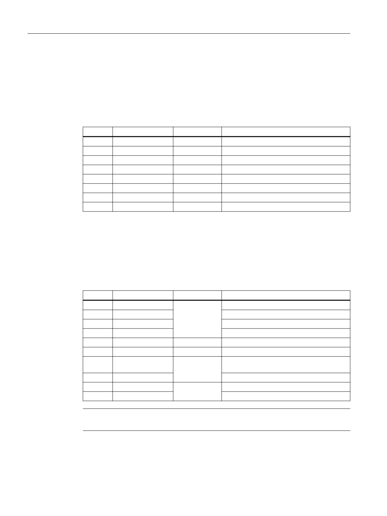
X7: Panel Present
Connector designa-
X7
tion:
Connector type:
6-pin Phoenix terminal
Table 1-2
Assignment of the interface Panel Present X7
Pin
Signal name
Signal type
Meaning
1
PRES
O
"High": Panel (HT 2) plugged in
2
XCTL
O
"Low": EMER STOP button pressed 1)
3
XFAULT
O
"Low": Error in emergency stop electronics 1)
4
N.C.
-
Not connected
5
N.C.
-
Not connected
6
M
P
Ground
1)
Function not implemented in Basic PN variant, output is not switched to "High"
X8: Emergency Stop wiring terminal
Connector designa-
X8
tion:
Connector type:
4-pin Phoenix terminal
Table 1-3
Assignment of the emergency stop wiring terminal X8
Pin
Protective circuit
1
On-board jumper
between 1 and 2
2
3
On-board jumper
between 3 and 4
4
Note
Use this terminal for simple routing of the emergency stop cables, optional.
The connector is only used to assist looping through. The connected pins 1 and 2 as well as
3 and 4 have no additional function on the connection module.
Handheld units
Manual, 03/2016, 6FC5397-1AP40-5BA3
29
Handheld Terminal HT 2
1.3 Connecting
X20: Enabling buttons
Connector designa-
X20
tion:
Connector type:
8-pin Phoenix terminal
Table 1-4
Assignment of the interface enabling buttons X20
Pin
Signal name
Signal type
Meaning
1
ZUST1P
I
Electronic enabling button 1 P
2
ZUST1M
O
Electronic enabling button 1 M
3
ZUST2P
I
Electronic enabling button 2 P
4
ZUST2M
O
Electronic enabling button 2 M
5
N.C.
-
Not connected
6
N.C.
-
Not connected
7
N.C.
-
Not connected
8
N.C.
-
Not connected
X21: Emergency stop and module supply voltage
Connector designa-
X21
tion:
Connector type:
10-pin Phoenix terminal
Table 1-5
Assignment of the interface Emergency Stop and Module Supply Voltage
Pin
Signal name
Signal type
Meaning
1
STOP23
Emergency Stop circuit
2
STOP24
Emergency Stop circuit
B
3
STOP13
Emergency Stop circuit
4
STOP14
Emergency Stop circuit
5
M
P
Ground
6
N.C.
-
-
7
IN_E9
Connected P24 (jumpered to Pin8 during opera-
P
tion)
8
P24_FILT
Filtered 24V module power supply
9
IN_E9_EXT
Feedback signal via connected P24
O
10
IN_E12_EXT
"High": Terminating connector plugged in
Note
Pins 7 and 8 must be jumpered in order to supply a handheld terminal with power.
Handheld units
30
Manual, 03/2016, 6FC5397-1AP40-5BA3
Handheld Terminal HT 2
1.3 Connecting
1.3.3.3
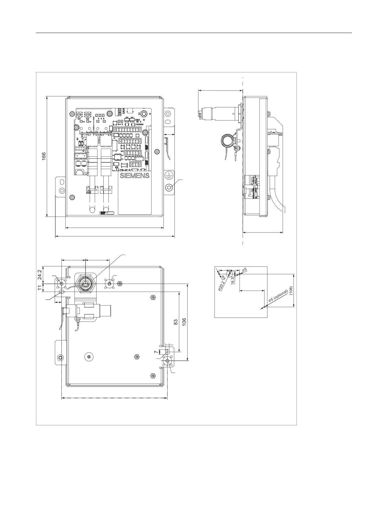
Dimension drawing
;
;
;
;
;
;
;
0
JURXQGLQJ
0D[ WLJKWHQLQJ WRUTXH
1P
0
0
0RXQWLQJ KROHV
0
RSWLRQDO
(ORQJDWHG KROHV LI PRGXOHV DUH VFUHZHG WR WKH LQVLGH RI WKH FRQWURO FDELQHW
Image 1-17 Connection module Basic PN - dimension drawing for control cabinet installation
Handheld units
Manual, 03/2016, 6FC5397-1AP40-5BA3
31
Handheld Terminal HT 2
1.3 Connecting
1.3.3.4
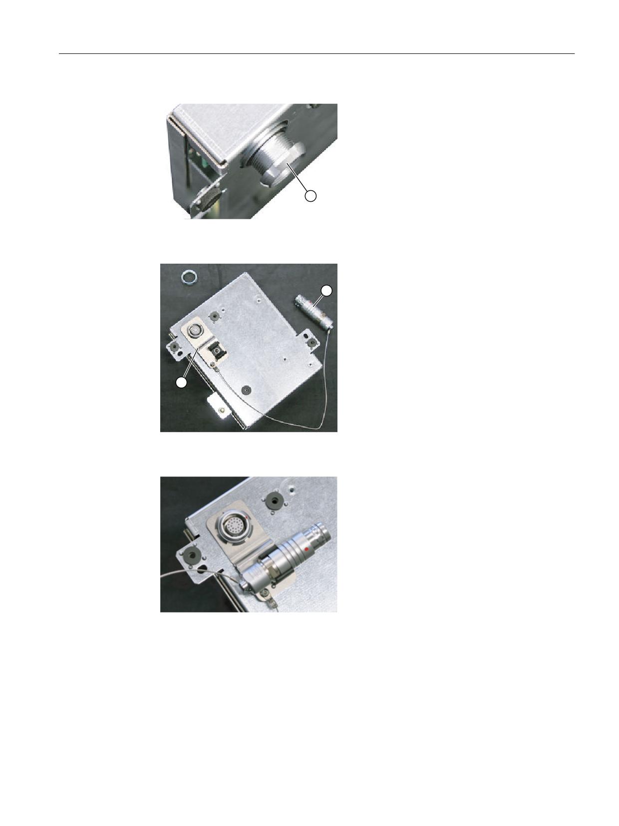
Installing the terminating connector
Procedure
Note
If you never remove the HT 2 from the connection module, it is not necessary to attach the
terminating connector.
Handheld units
32
Manual, 03/2016, 6FC5397-1AP40-5BA3
Handheld Terminal HT 2
1.3 Connecting
1.Unscrew the fixing nut ①.
2.Attach the bracket ① for the terminating
connector ②.
3.Tighten the retaining nut and insert the ter-
minating connector into the bracket.
Handheld units
Manual, 03/2016, 6FC5397-1AP40-5BA3
33
Handheld Terminal HT 2
1.3 Connecting
1.3.4
Connection examples of enabling button and emergency stop button
This section contains connection examples for enabling and emergency stop buttons
corresponding to Category 3 PL d in accordance with EN ISO 13849-1:2008.
Note
To ensure Category 3 PL d in accordance with EN ISO 13849-1:2008, be sure to follow the
operating instructions for the monitoring device being used.
The monitoring devices shown in the following examples satisfy Category 4 PL e in accordance
with EN ISO 13849-1:2008.
The monitoring device and downstream components should be taken into consideration when
calculating the overall "Enabling" safety function.
Handheld units
34
Manual, 03/2016, 6FC5397-1AP40-5BA3
Handheld Terminal HT 2
1.3 Connecting
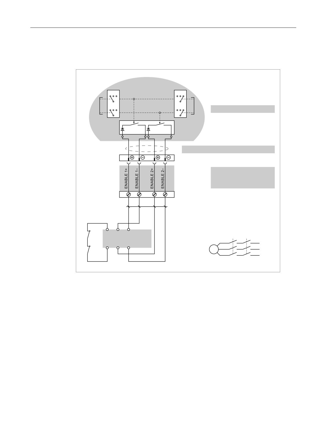
Connection - enabling button with evaluation unit
The diagram shows the connection of an evaluation unit with the enabling buttons of the HT 2.
(QDEOLQJ EXWWRQ RQ WKH OHIW
(QDEOLQJ EXWWRQ RQ WKH ULJKW
OHYHOV FLUFOHV
OHYHOV FLUFOHV
&LUFOH
&LUFOH
+7
(YDOXDWLRQ HOHFWURQLFV
&LUFOH
&LUFOH
&RQQHFWLQJ FDEOH V
7HUPLQDO ER[ 31 3OXV %DVLF
RU
FRQQHFWLRQ PRGXOH %DVLF 31
7HUPLQDO VWULS
PP PLQ &X
.$
(YDOXDWLRQ XQLW IRU
.$
.%
HQDEOLQJ EXWWRQ
/
.%
0
/
/
Image 1-18 Enabling button with evaluation unit
All contacts of the safety relay (contactor) KA and KB are fitted with positively-driven contacts
in accordance with EN 50205:2002.
Handheld units
Manual, 03/2016, 6FC5397-1AP40-5BA3
35
Handheld Terminal HT 2
1.3 Connecting
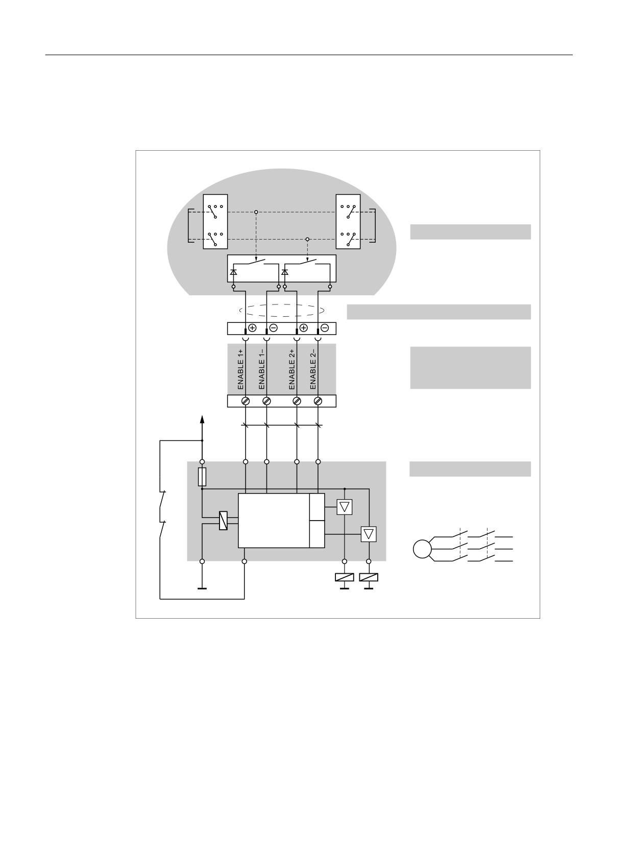
Connection - enabling button with safety relay
The diagram shows the connection of safety switching device SIRIUS 3TK2841 with the
enabling buttons of the HT 2.
(QDEOLQJ EXWWRQ RQ WKH OHIW
(QDEOLQJ EXWWRQ RQ WKH ULJKW
OHYHOV FLUFOHV
OHYHOV FLUFOHV
&LUFOH
&LUFOH
+7
(YDOXDWLRQ HOHFWURQLFV
&LUFOH
&LUFOH
&RQQHFWLQJ FDEOH V
&RQQHFWLRQ ER[ 31 3OXV %DVLF
RU
FRQQHFWLRQ PRGXOH %DVLF 31
7HUPLQDO VWULS
SLQ
'&
9
PP PLQ &X
$
<
<
<
<
0RQLWRULQJ GHYLFH
.$
6,5,86
7.
.$
.%
.%
/
0
/
/
$ ದ
<
.$
.%
*1'
*1'
Image 1-19 Enabling button with safety relay
All contacts of the safety relay (contactor) KA and KB are fitted with positively-driven contacts
in accordance with EN 50205:2002.
Handheld units
36
Manual, 03/2016, 6FC5397-1AP40-5BA3
Handheld Terminal HT 2
1.3 Connecting
Connection - emergency stop button with safety relay
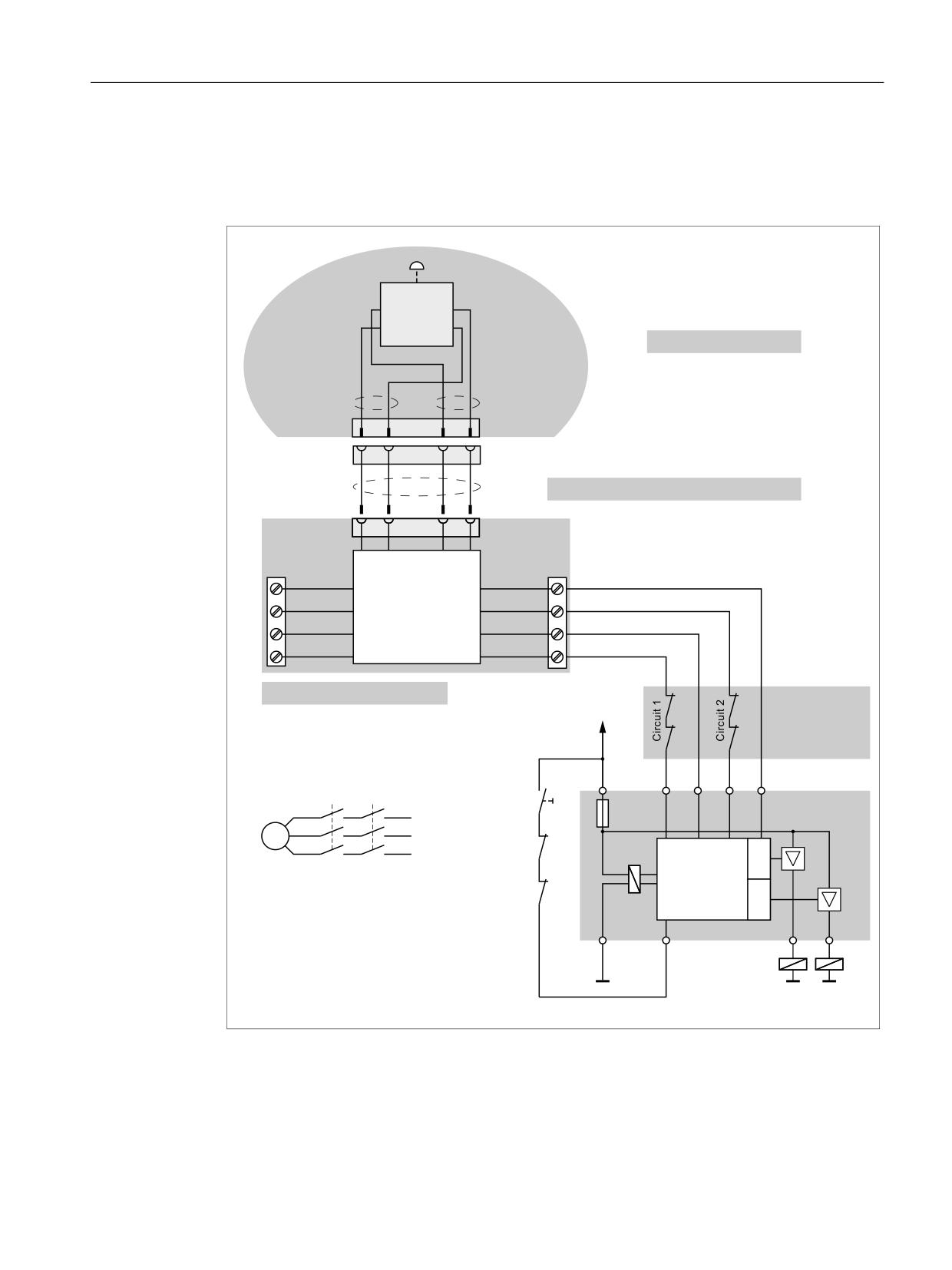
The following figure shows the connection of the SIRIUS 3TK2822 or SIRIUS 3TK2841 safety
relay to the emergency stop button of the HT 2.
(PHUJHQF\ VWRS EXWWRQ
FLUFXLW SRVLWLYH RSHQLQJ RSHUDWLRQ
+7
&LUFXLW
&LUFXLW
&RQQHFWLRQ FDEOH
7HUPLQDO VWULS
7HUPLQDO VWULS
SLQ
SLQ
&7/
6723
&7/
6723
35(6
6723
35(6
6723
0RQLWRULQJ GHYLFH
6WRS FLUFXLW
9
'&
RU
HPHUJHQF\ VWRS
FLUFXLW
$
<
<
<
<
.$
.%
2Q
/
0
/
.$
/
6,5,86
7.
.%
7.
$ ದ
<
.$
.%
*1'
*1'
Image 1-20 Emergency stop button with safety relay
All contacts of the safety relay (contactor) KA and KB are fitted with positively-driven contacts
in accordance with EN 50205:2002.
Monitoring outputs may not be used for safety-related functions.
Handheld units
Manual, 03/2016, 6FC5397-1AP40-5BA3
37
Handheld Terminal HT 2
1.3 Connecting
1.3.5
Connecting cable
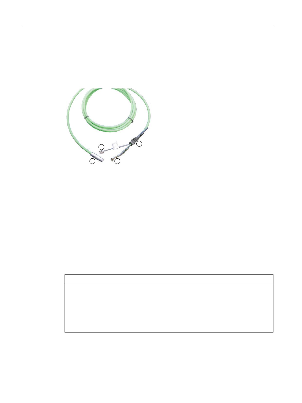
The connecting cable is an industrial cable and, thus, resistant to many solvents and lubricants.
The flexural strength is geared to the actual usage conditions.
The connecting cable is available in different lengths. You will find information in Section:
"Accessories".
① Metallic push-pull circular connector (ODU connector)
② Strain relief and kink protection for connecting cable
③ Plug connector for enabling button, emergency stop, 24 V and safety signals
④ RJ45 connector (Ethernet connection)
Image 1-21 Connecting cable of the HT 2
The connecting cable is connected to the HT 2 via the RJ 45 connector (3) and the plug
connector (4). The ODU connector (1) serves to connect the connecting cable to the terminal
box PN or the connection module PN (control cabinet installation). The tightening torque for
the nut of the ODU socket is 6.5 Nm.
The HT 2 has one cable entry on its rear side for connecting the cable. It is located under the
cover (see Section: "Control and display elements" → "Overview").
Laying the connecting cable
NOTICE
Damage to components
Only open the connection slot when the power supply voltage is switched off. Otherwise,
components could be destroyed or non-defined signal states can occur.
When the connection slot is open, the Handheld Terminal HT 2 is sensitive with respect to
electrostatic discharge.
Do not remove the ESD protection when opening the device.
Handheld units
38
Manual, 03/2016, 6FC5397-1AP40-5BA3
Handheld Terminal HT 2
1.3 Connecting
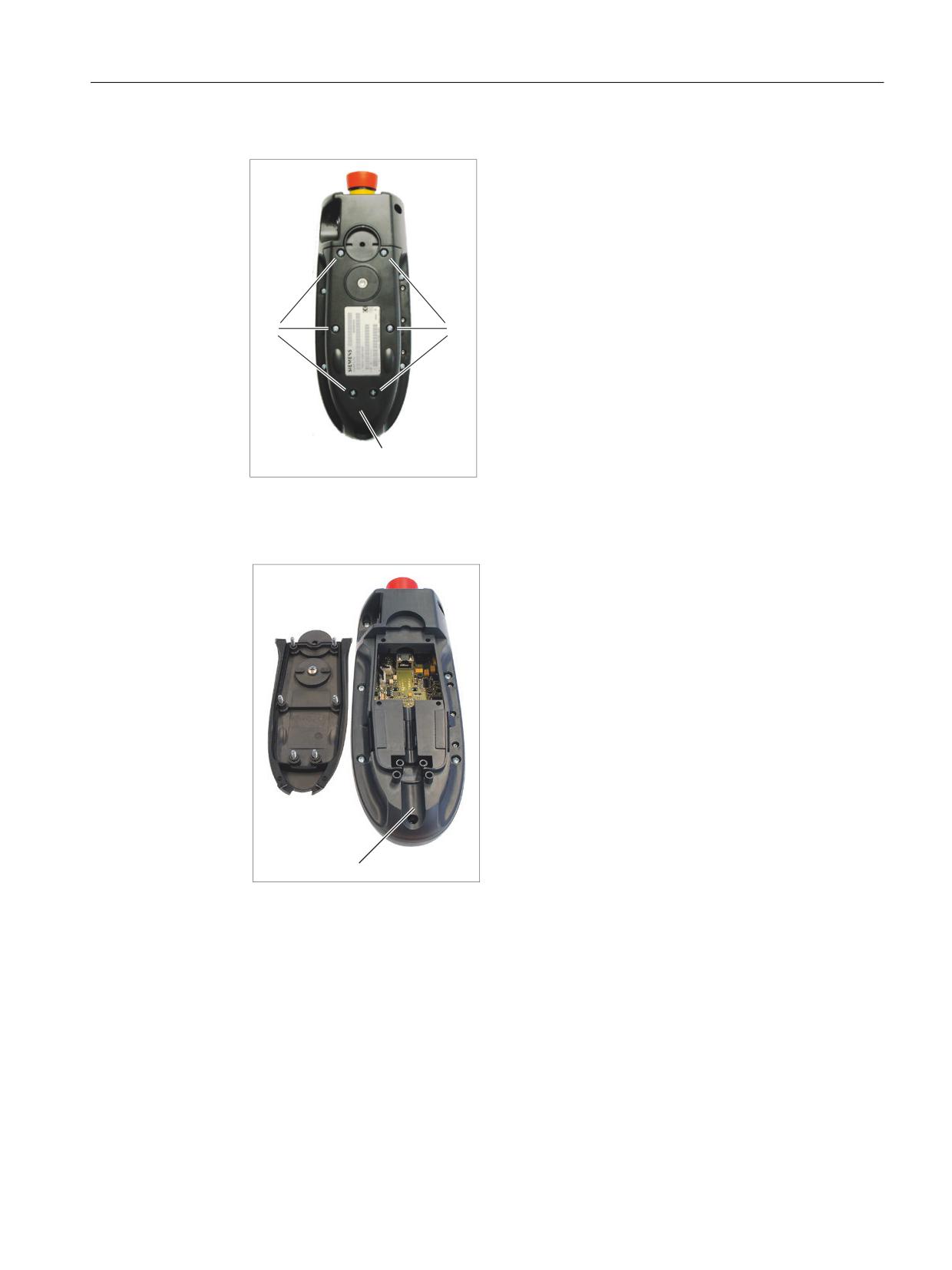
1.Place the device on a soft, horizontal surface so
that the operator control components are not me-
chanically damaged.
Open the cable duct cover (2) by unscrewing the
six PT screws (4 x 20 mm) approximately 1 cm
(1).
To do this, use a crosstip size 2 screw driver.
Cable duct cover open
(1) Cable entry
Handheld units
Manual, 03/2016, 6FC5397-1AP40-5BA3
39
Handheld Terminal HT 2
1.3 Connecting
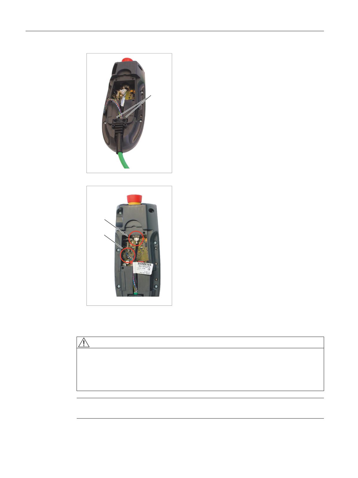
2.Insert the connecting cable into the cable entry.
Gently press the cable downwards until it is com-
pletely retained by the retaining elements (1).
Ensure that the cable doesn't sag away from the
mounting surface, but is located flush to the
mounting surface. Otherwise, the device could
be pulled down to the floor and damaged.
In order to avoid damaging the cable sheath, do
not route it over sharp edges.
3.Connect the RJ-45 connector(1) to the Ethernet
socket.
Press the plug connector (2) firmly into the pow-
er supply socket.
WARNING
Improper installation of the cable can result in failure of the safety functions.
When plugging in the connector plug, ensure that all cables are lying straight in the cable
guide. Check to ensure that all wires are aligned and straight and check the firm seating of
the plug connector before replacing the cable duct cover. Make sure that the cable sleeve is
installed correctly.
Note
Check to see that the cable label is not jammed in the seal.
Handheld units
40
Manual, 03/2016, 6FC5397-1AP40-5BA3
Handheld Terminal HT 2
1.3 Connecting
4.Put the cable duct cover on and secure it by
tightening the six screws.
NOTICE
Damage to the thread in the fastening holes
The housing of the HT 2 is made of plastic. Therefore, the mounting hole threads cannot
handle the same amount of stress as a comparable metallic housing. Therefore, do not
exceed 0.4 to 0.5 Nm of torque when tightening the screws (also for protecting the connecting
cable).
If you use a power screwdriver, ensure the max. speed of 600 rpm is adhered to (torque: 1
Nm).
The screws of the cable duct cover may only be loosened or tightened a maximum of 20
times. Otherwise, there is the danger that the threads might become damaged and the seal
of the housing will be compromised which could lead to failure of the device.
1.3.6
Power Supply
The HT 2 is supplied with power via the connecting cable of the terminal box PN or of the
connection module PN.
The input voltage range is designed for +24 VDC.
For further details, see: "General notes and interconnection" → "Operational planning"→
"General electrical conditions" → "Power supply".
1.3.7
Unplugging/plugging during operation
The ability to detect a connected HT 2 in the PLC
1. HW solution:
The X7 interface of the connection module PN Basic signals "HT 2 Present" at pin 1 for the
"active" connection module (see Section: "Connections" → "Connection module PN Basic"
→ "Interfaces").
If the connection module is "inactive", this signal is not set.
This makes the "active" connection module detectable in the PLC by wiring the above-
mentioned pins of all connection modules to digital I/Os on PLC I/O modules.
2. Permanently configured MCPs / HT 2 on one control:
If there are only permanently configured MCPs / HT 2 on a control, removal of the MCP or
HT 2 triggers the PLC alarm "400260 Machine Control Panel failed".
Based on this, an "active" or "inactive" MCP / HT 2 in the PLC can be detected.
The failure of an MCP / HT 2 is, however, only detected in the PLC if max. 2 MCP / HT 2
are permanently configured and no MCP changeover by means of FB9 (e.g. triggered by
HMI when operator focus is switched).
Handheld units
Manual, 03/2016, 6FC5397-1AP40-5BA3
41
Handheld Terminal HT 2
1.4 Commissioning
1.4
Commissioning
1.4.1
BIOS
1.4.1.1
BIOS powering up
After you have switched-in the power supply voltage of the HT 2, the BIOS initializes the
hardware and boots the system.
All LEDs are briefly activated after the hardware has been initialized.
The HT 2 is ready for operation.
Note
If errors occur while booting, an appropriate message is displayed (see Section: "Error
messages").
1.4.1.2
Settings in the BIOS menu
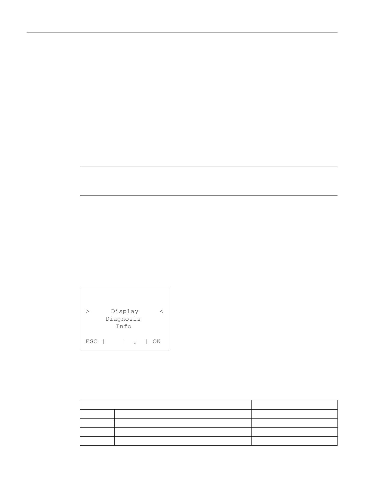
You can activate the BIOS menu by keeping the upper left key pressed while booting.
The BIOS main menu is opened.
Main menu
MAIN MENU
Image 1-22 BIOS - main menu of the HT 2
The available sub-menus are displayed at the center of the screen.
The functions that can be executed with the four keys of the upper row of keys (softkeys) are
listed in the bar at the lower edge.
Functions
Key
< ESC >
Exiting the main menu
Left (outside)
< ↑ >
Scrolling upwards
Left (center)
< ↓ >
Scrolling downwards
Right (center)
< OK >
Activating the selected menu item
Right (outside)
Handheld units
42
Manual, 03/2016, 6FC5397-1AP40-5BA3
Handheld Terminal HT 2
1.4 Commissioning
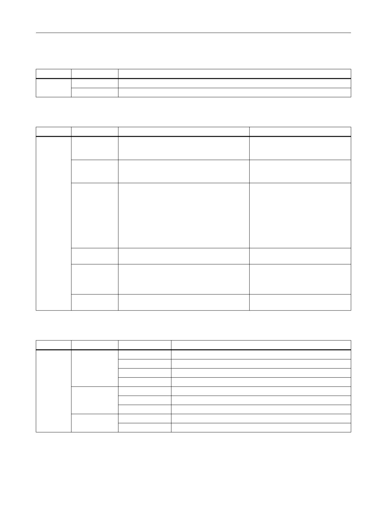
Submenu: Display
Submenu
Menu item
Significance
Display
Brightness
Setting the display brightness
Contrast
Setting the display contrast
Submenu: Diagnostics
Submenu
Menu item
Significance
Notes
Diagnostics
LEDs
The LEDs are switched-in one after the other in the
With this test, ensure that all of the
form of a running light.
LEDs light up and no LED remains per-
manently lit up.
Keyboard
Visualizing the pressed keys. Multiple keys can be
The upper left key exits this test.
simultaneously pressed. In addition, the LEDs of
all pressed keys are lit.
Enabling switch
Displays the state of the two enabling button cir-
This test only checks the functionality
cuits.
of the enabling buttons.
- "Off"
This test does not include any of the
- "Enabled"
other safety-relevant components
- "Panic"
(e.g. correct connection of the ena-
bling function at the machine)!
If the state of a circuit is not correctly
displayed, then the device must be im-
mediately disabled.
Override switch
Displays the position of the override rotary switch
(value 0 to 18).
Key switch
Displays the key-operated switch position.
- "Off"
- "On (1)"
- "On (2)
Handwheel
Displays the actual counter state of the handwheel.
Each time that this menu item is called,
the counter state is reset to zero.
Submenu: Info
Submenu
Menu item
Sub point
Significance
Info
Hardware
Memory
Displays the size of the main memory in MB
Flash
Displays the size of the flash module in MB
Supply
Displays the power supply voltage in volt
Temperature
Displays the internal housing temperature in °C
Software
BIOS
Displays the version number of the BIOS
Boot loader
Displays the version number of the boot loader
Coprocessor
Displays the version number of the coprocessor firmware
Counters
Hours counter
Operating hours counter (units: hours)
Power on
Power-on counter
Handheld units
Manual, 03/2016, 6FC5397-1AP40-5BA3
43
Handheld Terminal HT 2
1.4 Commissioning
1.4.1.3
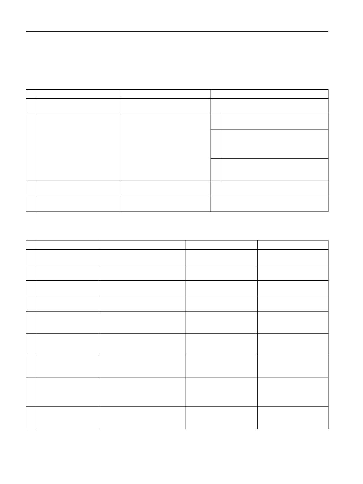
Error handling
Faults
#
Problem
Cause
Solution
1
No display
The power supply is interrupted.
Check the power supply connection.
- all LEDs off
If the fault remains, then the device is defective.
2
No display
The display contrast is incorrectly
1.
When powering-up, keep the lefthand
- LEDs briefly flash once
set.
(first) softkey pressed.
2.
Press once, one after the other
- the righthand (fourth) softkey
- the third softkey
- the righthand (fourth) softkey
3.
Using the second and third softkeys,
change the contrast until it is easy to read
the display.
3
No display
The display is defective.
- all LEDs flash permanently
4
Displays the message: "Test-
The "Testcommandhandler" was
Re-boot the HT 2.
commandhandler"
activated.
Error messages
#
Display
Description
Cause
Solution
1
SDRAM data line test
An error has occurred while test-
The hardware is defective.
failed!
ing the SDRAM data lines.
2
SDRAM data line test
An error has occurred while test-
The hardware is defective.
failed!
ing the SDRAM address lines.
3
SDRAM access test
An error has occurred when ac-
The hardware is defective.
failed!
cessing the SDRAM.
4
SDRAM fill test failed!
An error has occurred when writ-
The hardware is defective.
ing a test pattern to the SDRAM.
5
Unexpected SDRAM
The size of the SDRAM deter-
The hardware is defective.
size!
mined, does not correspond to
the expected size.
6
Wrong coprocessor ver-
The firmware of the ATmega88 is
The BIOS was updated -
Update the ATmega88 firm-
sion, update required!
too old.
however not the ATmega88
ware.
firmware.
7
Coprocessor communi-
An error has occurred for the cy-
cation error!
clic SPI communication with the
ATmega88.
8
BIOS code corrupted!
The BIOS checksum is invalid.
The BIOS has been corrup-
ted due to an unsuccessful
update or a defective flash
module.
9
Hardware info block in-
The hardware information block is
The block was corrupted
valid!
invalid.
when updating or the flash
module is defective.
Handheld units
44
Manual, 03/2016, 6FC5397-1AP40-5BA3

Handheld Terminal HT 2
1.4 Commissioning
#
Display
Description
Cause
Solution
10
Serial number not set!
The serial number is missing.
It is possible that the serial
number was deleted while
updating.
11
MAC ID not set!
There is no MAC ID.
The MAC ID may have
been deleted while updat-
ing.
12
No bootloader present!
There is no bootloader.
13
Bootloader code corrup-
The bootloader checksum is inva-
The bootloader has been
ted!
lid.
damaged due to an unsuc-
cessful update or a defec-
tive flash module.
14
Pressed keys detected!
One or several keys are pressed.
The hardware is defective if
no keys have been pressed.
15
Display error!
Reading back the display status
The hardware is defective.
was unsuccessful.
1.4.2
Interface signals
PLC module
The FC13 "HHUDisp" supports the handling of the LC display. For a detailed description,
please refer to:
Literature: Function Manual, Basic Functions, Basic PLC Program (P3).
Note
The customer is responsible for programming the transfer of key signals to the interface in a
PLC user program.
Handheld units
Manual, 03/2016, 6FC5397-1AP40-5BA3
45
Handheld Terminal HT 2
1.4 Commissioning
User interface
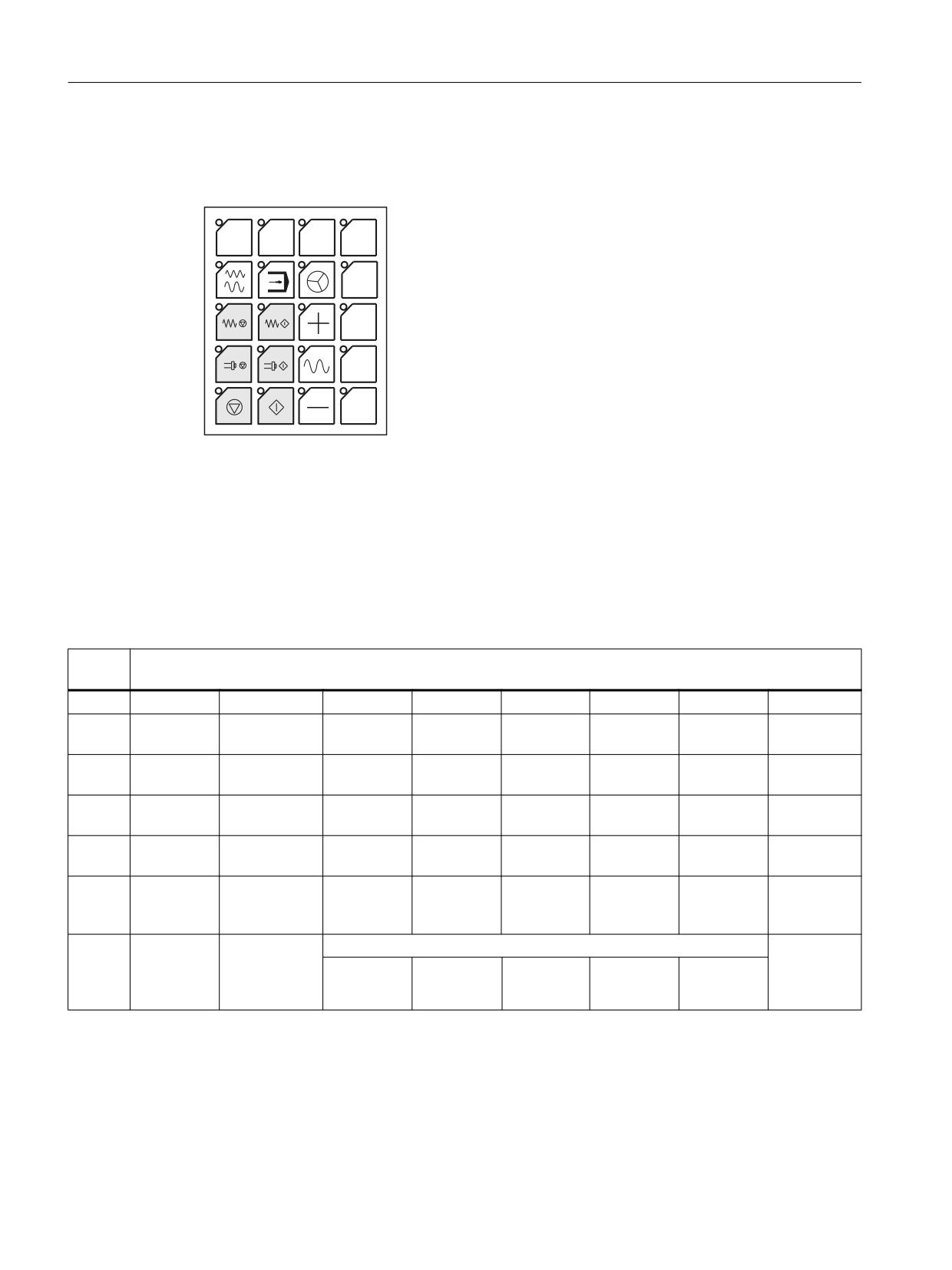
Layout of keys and LEDs
7
7
7
7
;
<
=
7+
$;,6
Image 1-23 Operator keys, standard assignment
The first row of keys (free keys T1 ... T4) is not assigned as standard.
Input image HT 2
You can tap the signals for the keys, feed rate override switch, key-operated switch and
acknowledgement of the digital display at the input area. The address range is set by parameter
assignment with STEP7 tools.
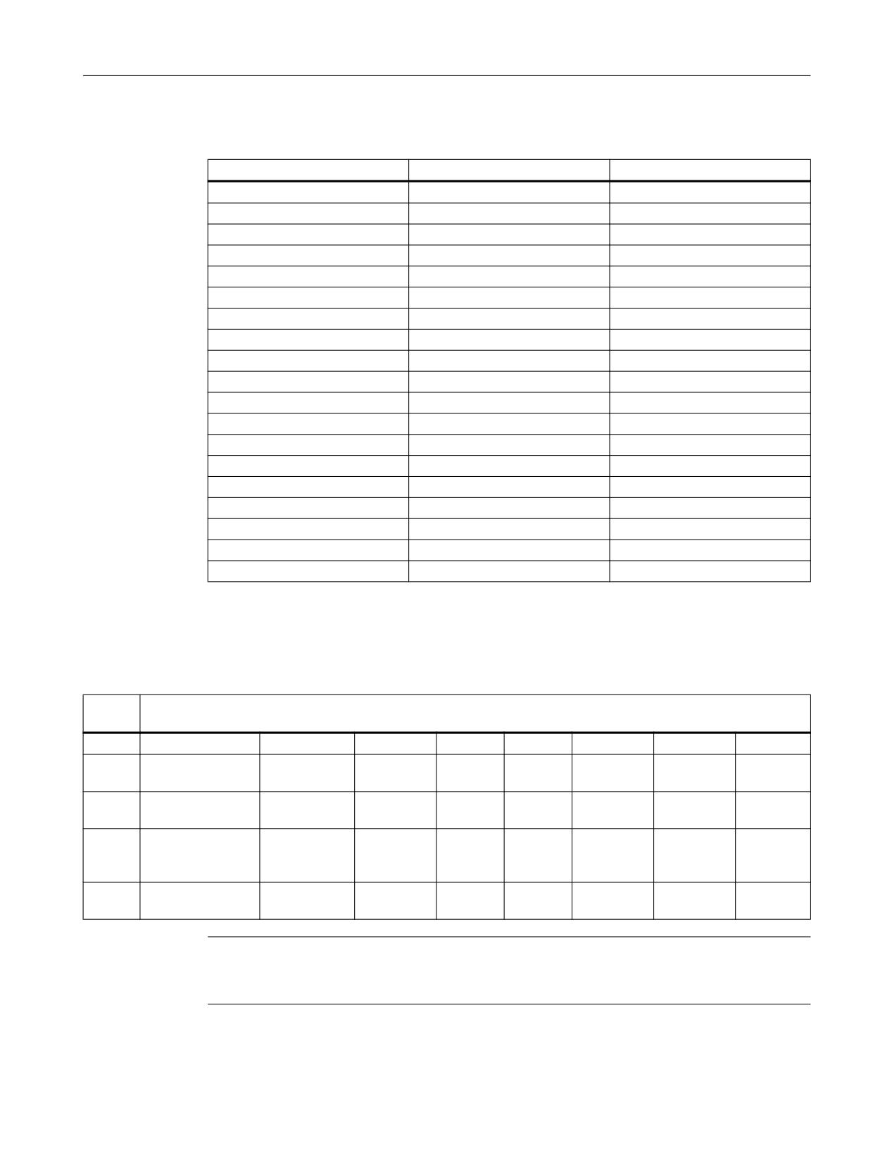
Byte
Input signals to PLC
no.
Byte
Bit 7
Bit 6
Bit 5
Bit 4
Bit 3
Bit 2
Bit 1
Bit 0
EB
Reserved
Reserved
Reserved
Reserved
Reserved
Reserved
Reserved
Reserved
m + 0
EB
Reserved
Reserved
Reserved
Reserved
Reserved
Reserved
Reserved
Reserved
m + 1
EB
Feed
Free
AUTO-
Spindle
Feed
Free
m + 2
start
T2 key
MATIC
NC stop
stop
stop
T1 key
JOG
EB
Free
4.
Spindle
m + 3
T3 key
Handwheel
Axis
Z
Y
X
NC Start
start
EB
Direction
Rapid tra-
Direction
Free
m + 4
key -
verse
key +
T4 key
override
EB
Acknowl-
Rapid traverse / feed rate override switch
m + 5
edgement
Keyswitch
E
D
C
B
A
digital
display
Handheld units
46
Manual, 03/2016, 6FC5397-1AP40-5BA3
Handheld Terminal HT 2
1.4 Commissioning
Rotary switch positions HT 2
Position
%
EDCBA
0
0
00001
1
1
00011
2
2
00010
3
4
00110
4
6
00111
5
8
00101
6
10
00100
7
20
01100
8
30
01101
9
40
01111
10
50
01110
11
60
01010
12
70
01011
13
75
01001
14
80
01000
15
85
11000
16
90
11001
17
95
11011
18
100
11010
Output image HT 2
The signals for controlling the LEDs, HHU mode, display signals and digital display are present
at the output area.
Byte
Output signals to the HHU
no.
Byte
Bit 7
Bit 6
Bit 5
Bit 4
Bit 3
Bit 2
Bit 1
Bit 0
AB
always
Free T4
Free
Free
Free
m + 0
1
key
T3 key
T2 key
T1 key
AB
New data for se-
Selection
Selection
m + 1
lected line
lines 3, 4
lines 1, 2
AB
Feed
Rapid tra-
AUTO-
NC stop
Spindle
Feed
Direction
JOG
m + 2
start
verse
MATIC
stop
stop
key +
override
AB
Direction
Handwheel
4.
Z
Y
X
NC Start
Spindle
m + 3
key -
Axis
start
Note
Output byte AB m + 0, bit 7 must always have the value '1'!
This sets the display's output mode.
Handheld units
Manual, 03/2016, 6FC5397-1AP40-5BA3
47

Handheld Terminal HT 2
1.4 Commissioning
Output image of the digital display
Control of the digital display in the HT 2
Byte
Output signals to the HHU
no.
Byte
Bit 7
Bit 6
Bit 5
Bit 4
Bit 3
Bit 2
Bit 1
Bit 0
AB
Default setting of 1st character (right) of selected line
m + 4
AB
Default setting of 2nd character of selected line
m + 5
AB
Default setting of 3rd character of selected line
m + 6
AB
Default setting of 4th character of selected line
m + 7
AB
Default setting of 5th character of selected line
m + 8
AB
Default setting of 6th character of selected line
m + 9
AB
Default setting of 7th character of selected line
m + 10
AB
Default setting of 8th character of selected line
m + 11
AB
Default setting of 9th character of selected line
m + 12
AB
Default setting of 10th character of selected line
m + 13
AB
Default setting of 11th character of selected line
m + 14
AB
Default setting of 12th character of selected line
m + 15
AB
Default setting of 13th character of selected line
m + 16
AB
Default setting of 14th character of selected line
m + 17
AB
Default setting of 15th character of selected line
m + 18
AB
Default setting of 16th character (left) of selected line
m + 19
Display
The digital display is used as a 4-line alphanumeric display with 16 digits per line.
The display data is coded according to the character set given in the ASCII code table for the
digital display via the ABm + 4...19 bytes. The decimal point is a separate character. The
Handheld units
48
Manual, 03/2016, 6FC5397-1AP40-5BA3
Handheld Terminal HT 2
1.4 Commissioning
display always starts line by line right-justified with the byte ABm + 4 and is built up towards
the left up to ABm + 19.
Selecting the line
ABm + 1, bit 0 and bit 1
This bit is used to select the line to be written.
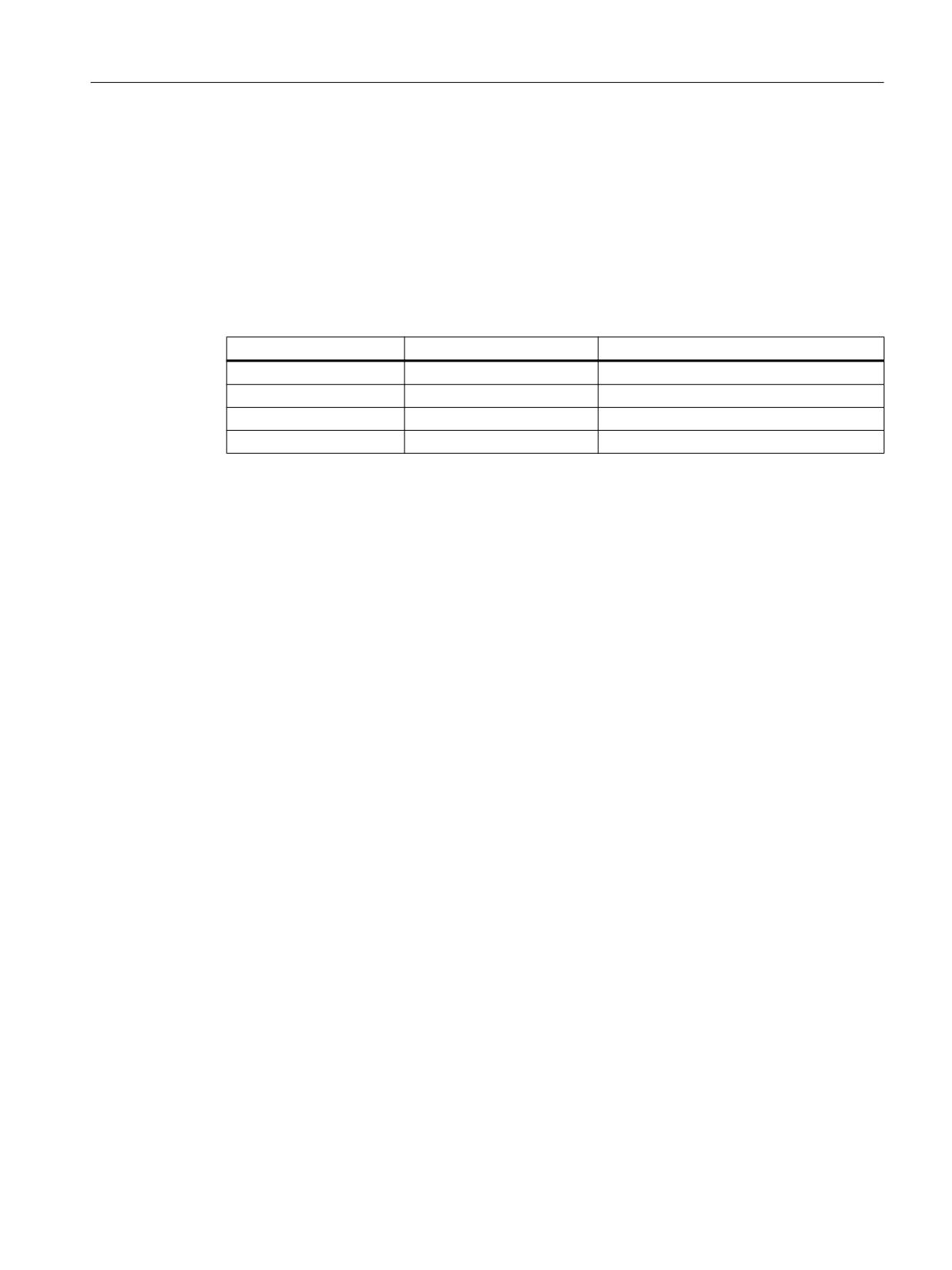
Table 1-6
Line selection
Bit 0
Bit 1
Selected line
0
0
1. 1st line
1
0
2. 2nd line
0
1
3. 3rd line
1
1
4. 4th line
New data for selected line
ABm + 1, bit 7
This bit is used to request writing in of new data into a line. The bit is set by the user program
and can be reset on detection of the acknowledgement bit EBm + 5, bit 7.
Bit 7 = 0: Reset request.
Bit 7 = 1: Set request
Acknowledgement of the digital display
EBm + 5, bit 7
This bit is set by the system after the new data has been accepted.
Bit 7 = 0: No new data
Bit 7 = 1: New data has been accepted
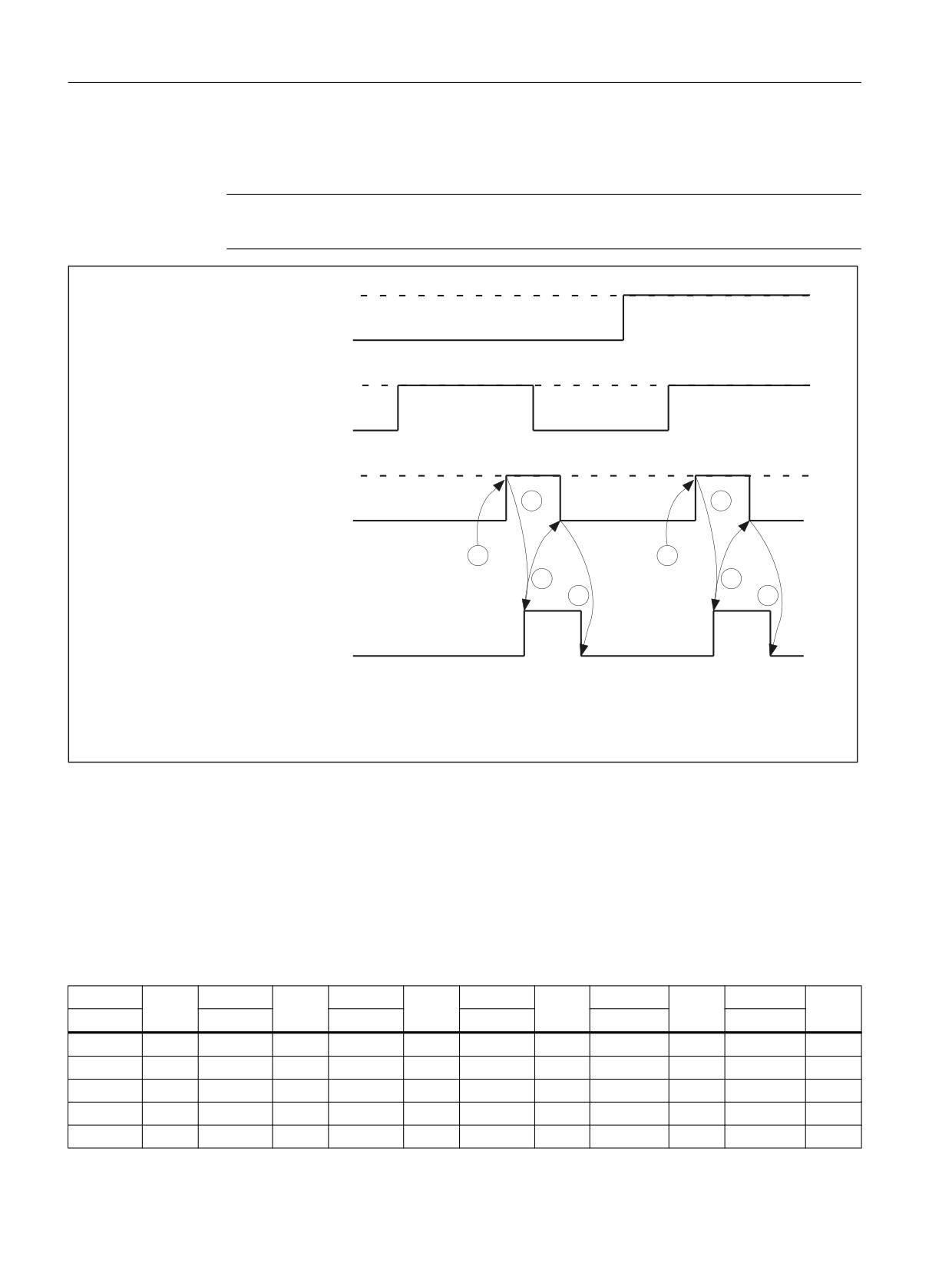
Example of a signal chart
Example of a signal chart when writing data for two lines 1 and 2
1. Select the line with ABm + 1, bit 0 and bit 1.
2. Write new data with ABm + 4...19.
3. Set request: New data for selected line ABm + 1, bit 7
Handheld units
Manual, 03/2016, 6FC5397-1AP40-5BA3
49
Handheld Terminal HT 2
1.4 Commissioning
4. Acknowledgement digital display EBm + 5, bit 7, via system.
5. Reset request
Note
The request must be reset before a new line is written!
1
/LQH
6HOHFWLQJ WKH OLQH
/LQH
0
1
'DWD IRU
'DWD IRU
:ULWLQJ QHZ GDWD
/LQH
/LQH
0
1
5HTXLUHPHQW QHZ GDWD
b
b
0
a
a
c
c
d
d
1
$FNQRZOHGJHPHQW GLJLWDO GLVSOD\
0
D 3/& XVHU VHWV WKH VLJQDO DQG ZDLWV IRU DFNQRZOHGJPHQW
E 6\VWHP VHWV DFNQRZOHGJPHQW
F 8VHU VHWV UHTXHVW EDFN
G 6\VWHP VHWV DFNQRZOHGJPHQW EDFN
Image 1-24 HT2 signal characteristic example for writing data into the HT 2 display
Proceed in the same way for the selection of line 3 and line 4
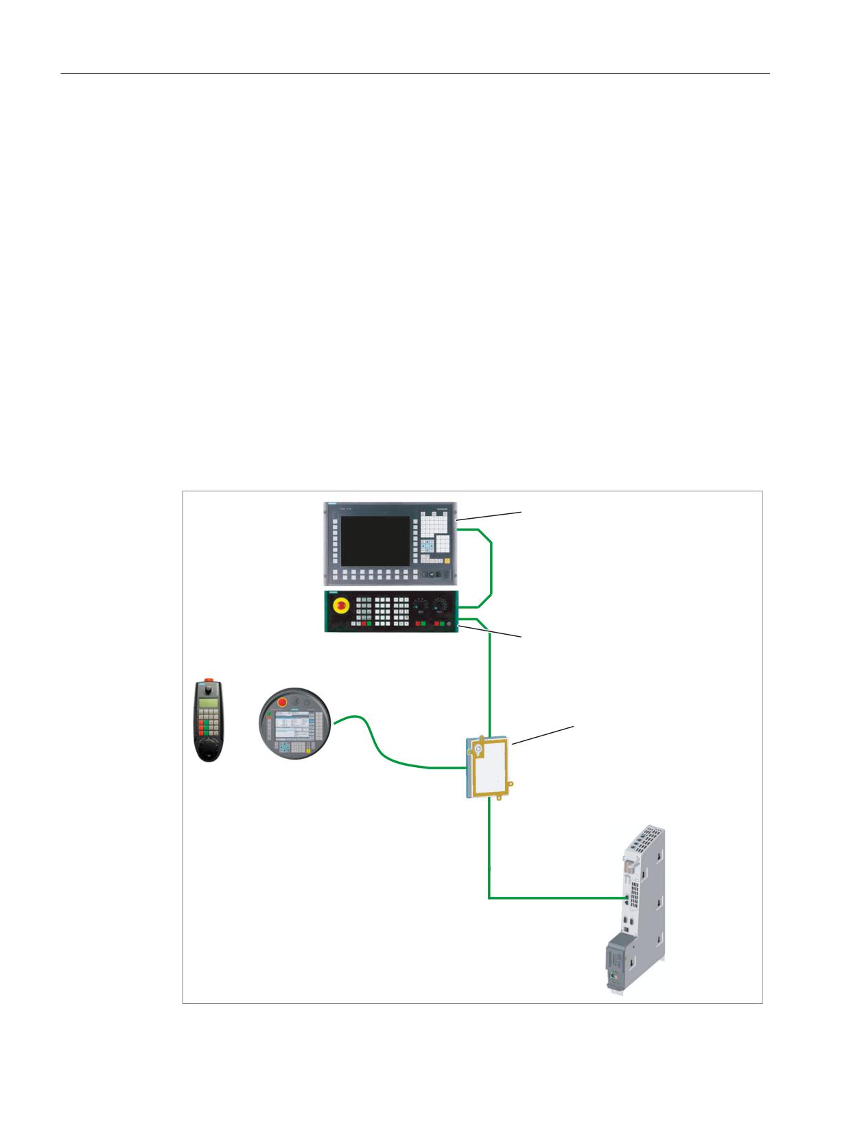
ASCII code for digital display
Representation of characters by specifying the corresponding number system (hexadecimal/
decimal) in the bytes ABm + 4...19. The characters from Hex 20 to Hex 7F are default values.
Table 1-7
Standard character set
ASCII
Char-
ASCII
Char-
ASCII
Char-
ASCII
Char-
ASCII
Char-
ASCII
Char-
acter
acter
acter
acter
acter
acter
Hex/dec
Hex/dec
Hex/dec
Hex/dec
Hex/dec
Hex/dec
1)
20 / 32
30 / 48
0
40 / 64
@
50 / 80
P
60 / 96
`
70 / 112
p
21 / 33
!
31 / 49
1
41 / 65
O
51 / 81
Q
61 / 97
a
71 / 113
q
22 / 34
"
32 / 50
2
42 / 66
B
52 / 82
R
62 / 98
b
72 / 114
r
23 / 35
#
33 / 51
3
43 / 67
C
53 / 83
S
63 / 99
c
73 / 115
s
24 / 36
$
34 / 52
4
44 / 68
D
54 / 84
T
64 / 100
d
74 / 116
t
Handheld units
50
Manual, 03/2016, 6FC5397-1AP40-5BA3

Handheld Terminal HT 2
1.4 Commissioning
ASCII
Char-
ASCII
Char-
ASCII
Char-
ASCII
Char-
ASCII
Char-
ASCII
Char-
acter
acter
acter
acter
acter
acter
Hex/dec
Hex/dec
Hex/dec
Hex/dec
Hex/dec
Hex/dec
25 / 37
%
35 / 53
5
45 / 69
E
55 / 85
U
65 / 101
e
75 / 117
u
26 / 38
&
36 / 54
6
46 / 70
F
56 / 86
V
66 / 102
f
76 / 118
v
27 / 39
'
37 / 55
7
47 / 71
G
57 / 87
W
67 / 103
g
77 / 119
w
28 / 40
(
38 / 56
8
48 / 72
H
58 / 88
X
68 / 104
h
78 / 120
x
29 / 41
)
39 / 57
9
49 / 73
I
59 / 89
Y
69 / 105
i
79 / 121
y
2A / 42
*
3A / 58
:
4A / 74
J
5A / 90
Z
6A / 106
j
7A / 122
z
2B / 43
+
3B / 59
;
4B / 75
K
5B / 91
[
6B / 107
k
7B / 123
{
2C / 44
,
3C / 60
<
4C / 76
L
5C / 92
\
6C / 108
l
7C / 124
|
2D / 45
-
3D / 61
=
4D / 77
M
5D / 93
]
6D / 109
m
7D / 125
}
2E / 46
3E / 62
>
4E / 78
N
5E / 94
^
6E / 110
n
7E / 126
~
2)
2F / 47
/
3F / 63
?
4F / 79
O
5F / 95
_
6F / 111
o
7F / 127
1)
Space
2
Not defined
Table 1-8
Extended character set
ASCII
Char-
ASCII
Char-
ASCII
Char-
ASCII
Char-
ASCII
Char-
ASCII
Char-
acter
acter
acter
acter
acter
acter
Hex/dec
Hex/dec
Hex/dec
Hex/dec
Hex/dec
Hex/dec
1)
A0 / 160
B0 / 176
°
C0 / 192
À
D0 / 208
Ð
E0 / 224
à
F0 / 240
ð
A1 / 161
¡
B1 / 177
±
C1 / 193
Á
D1 / 209
Ñ
E1 / 225
á
F1 / 241
ñ
A2 / 162
¢
B2 / 178
²
C2 / 194
Â
D2 / 210
Ò
E2 / 226
â
F2 / 242
ò
A3 / 163
£
B3 / 179
³
C3 / 195
Ã
D3 / 211
Ó
E3 / 227
ã
F3 / 243
ó
A4 / 164
¤
B4 / 180
´
C4 / 196
Ä
D4 / 212
Ô
E4 / 228
ä
F4 / 244
ô
A5 / 165
¥
B5 / 181
µ
C5 / 197
Å
D5 / 213
Õ
E5 / 229
å
F5 / 245
õ
A6 / 166
¦
B6 / 182
¶
C6 / 198
Æ
D6 / 214
Ö
E6 / 230
æ
F6 / 246
ö
A7 / 167
§
B7 / 183
·
C7 / 199
Ç
D7 / 215
×
E7 / 231
ç
F7 / 247
÷
A8 / 168
¨
B8 / 184
¸
C8 / 200
È
D8 / 216
Ø
E8 / 232
è
F8 / 248
ø
A9 / 169
©
B9 / 185
¹
C9 / 201
É
D9 / 217
Ù
E9 / 233
é
F9 / 249
ù
AA / 170
ª
BA / 186
º
CA / 202
Ê
DA / 218
Ú
EA / 234
ê
FA / 250
ú
AB / 171
«
BB / 187
»
CB / 203
Ë
DB / 219
Û
EB / 235
ë
FB / 251
û
AC / 172
¬
BC / 188
¼
CC / 204
Ì
DC / 220
Ü
EC / 236
ì
FC / 252
ü
2)
AD / 173
BD / 189
½
CD / 205
Í
DD / 221
Ý
ED / 237
í
FD / 253
ý
AE / 174
®
BE / 190
¾
CE / 206
Î
DE / 222
Þ
EE / 238
î
FE / 254
þ
AF / 175
¯
BF / 191
¿
CF / 207
Ï
DF / 223
ß
EF / 239
ï
FF / 255
ÿ
1)
Protected space
2)
Conditional separator
Handheld units
Manual, 03/2016, 6FC5397-1AP40-5BA3
51
Handheld Terminal HT 2
1.4 Commissioning
1.4.3
Application example for HT8 and HT 2 involving mixed operation
Prerequisite
The following example relates to an 840D sl plus TCU with MCP xxx PN and an optional HT 8
or HT 2 connected to a PN box. All the components are connected to X120 of the NCU. The
application example is equally valid for an MPP xxx IE H (with connection for HT 2/HT 8) instead
of a connection module /erminal box.
The TCU and HT 8 function as "thin client units" and as soon as they assume the operating
focus, they use their MCP address (db19.dbb123) and index (db19.dbb118) to register with
the PLC.
This setting is specified for both devices during the initial connection and is stored on the NCU's
CompactFlash card (config.ini).
By contrast, the HT 2 does not function as a "thin client unit". Consequently, it does not inform
the PLC whether it is connected; it is addressed in the PLC via the DIP switch position of the
connection point (PN box/module or MPP xxx IEH).
7&8
0DFKLQH FRQWURO SDQHO
(LWKHU
+7
RU
+7
&RQQHFWLRQ PRGXOH 31 RU
DOWHUQDWLYHO\ D WHUPLQDO ER[ 31
1&8
Handheld units
52
Manual, 03/2016, 6FC5397-1AP40-5BA3
Handheld Terminal HT 2
1.4 Commissioning
Configuration involving HT 8
The following is assumed:
TCU: MCP address = 192, index = 7
HT 8: MCP address = 10, index = 10
PN box DIP switch position = 10
Depending on whether we are dealing with the TCU or HT 8, either the MCP xxx PN or the
integrated HT8_MCP should now be activated.
To do this, perform the following on the PLC:
Depending on whether it is the TCU or the HT 8 that has the operating focus (db19.dbb123),
the relevant MCP bus address must be modified in DB7 ("gp_par"):
● Deactivate MCP via
"gp_par".MCP1Stop = 1
● Define MCP address via
"gp_par".MCP1BusAdr = db19.dbb123
● Activate MCP via
"gp_par".MCP1Stop = 0
Configuration involving HT 2
To activate the HT 2, proceed as follows:
● Check whether the TCU has the operating focus (HT 8 disconnected/db19.dbb123==192).
● Activate the HT 2, e.g. via button using "gp_par".BHGStop = 0.
Relevant entries in OB100:
CALL FB 1, DB 7
MCPNum :=
1
MCP1In :=
P#E 0.0
MCP1Out :=
P#A 0.0
MCP1StatSend :=
P#A 8.0
MCP1StatRec :=
P#A 12.0
MCP1BusAdr :=
10
//<<-- MCP_addr. for HT 8
corresp. TCU settings / or
for MCP 483 xxx PN
MCPBusType :=
B#16#55
//55=Ethernet
BHG :=
5
//5=Ethernet = HT 2
BHGIn :=
P#M 300.0
BHGOut :=
P#M 320.0
BHGRecGDNo :=
10
//= DIP switch position on
PN box (or MPP xxx IE) to
which HT 2 is connected
Handheld units
Manual, 03/2016, 6FC5397-1AP40-5BA3
53
Handheld Terminal HT 2
1.4 Commissioning
1.4.4
Application example for two HT 2 units connected to SINUMERIK
Prerequisite
The following example relates to the operation of two HT 2 units on one network. The aim is
to switch over from one HT 2 to the other. The following is assumed:
● There are two PN boxes on the network (with DIP switch positions 10 and 11).
● There is an HT 2 unit connected to each of these, but only one of them is activated.
The application example is equally valid for an MPP xxx IE H (with connection for HT 2) instead
of a connection module / terminal box.
Activating an HT 2
The HT 2 that is being activated is addressed by specifying the DIP switch position in
"gp_par".BHGRecGDNo.
Switchover during operation:
● Deactivate HHU via
"gp_par".BHGStop = 1
● Modify the PN box assignment via
"gp_par".BHGRecGDNo = 10 or 11
● Activate HHU via
"gp_par".BHGStop = 0
If there is only one HT 2, it is sufficient to specify these parameters by means of FB1 parameter
assignment in OB100 (DIP switch position 10):
CALL FB 1, DB 7
MCPNum :=
1
MCP1In :=
P#E 0.0
MCP1Out :=
P#A 0.0
MCP1StatSend :=
P#A 8.0
MCP1StatRec :=
P#A 12.0
MCP1BusAdr :=
10
//<<-- MCP_addr. for HT 8
corresp. TCU settings / or
for MCP 483 xxx PN
MCPBusType :=
B#16#55
//55=Ethernet
BHG :=
5
//5=Ethernet = HT 2
BHGIn :=
P#M 300.0
BHGOut :=
P#M 320.0
BHGRecGDNo :=
10
//= DIP switch position on
PN box (or MPP xxx IE) to
which HT 2 is connected
Handheld units
54
Manual, 03/2016, 6FC5397-1AP40-5BA3
Handheld Terminal HT 2
1.6 Maintenance and Service
1.5
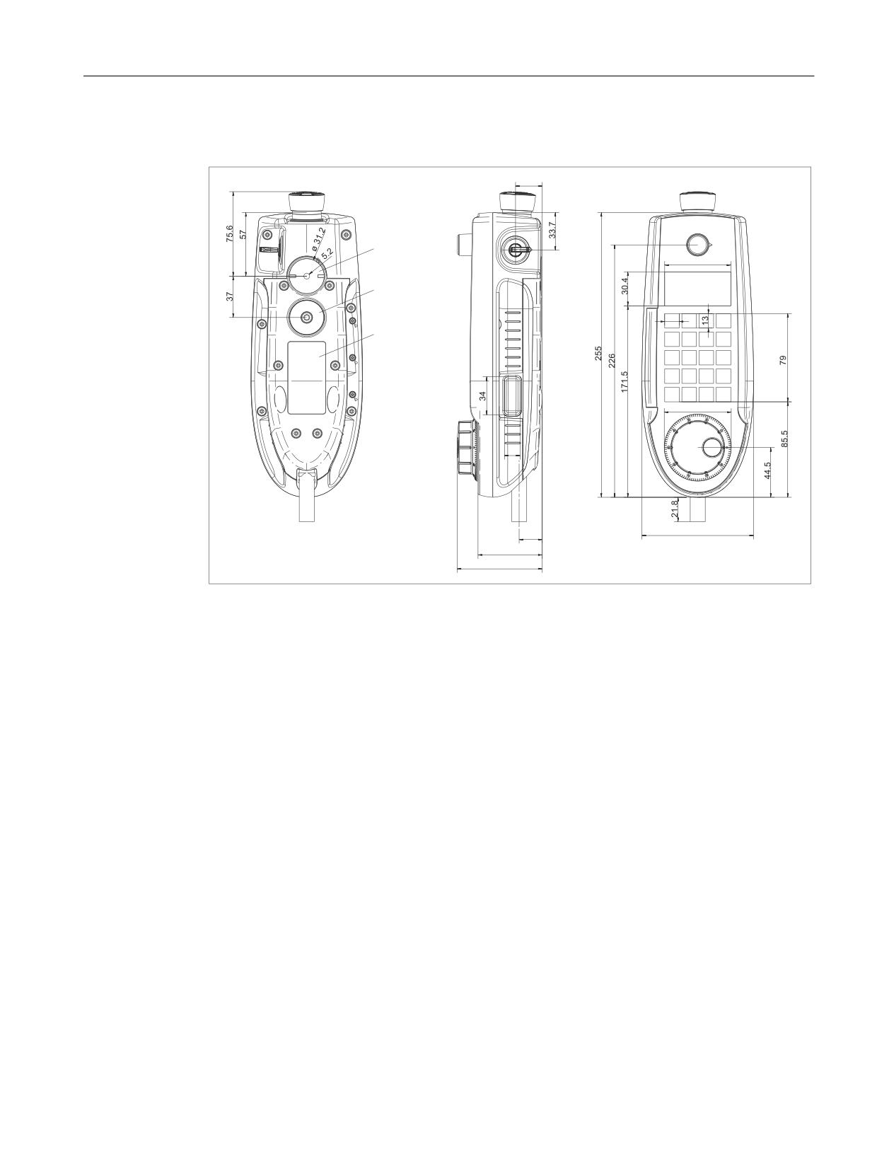
Dimension drawing
º
(1)
Standard position mounting bracket (optional: Retaining magnet)
(2)
Standard position retaining magnet (optional: mounting bracket)
(3)
Position for the type plate
Image 1-25 HT 2 - dimension drawing
1.6
Maintenance and Service
Cleaning the device
Use a soft cloth moistened either with water or a mild cleaning agent to clean the housing,
display and operator control elements of the HT 2.
Checking the device
In order to prevent foreign bodies or liquids entering the HT 2, regularly check the device
● that all the housing screws are in place and tight
● for damage to the housing
● for damage to the cable cover or cable entry
Handheld units
Manual, 03/2016, 6FC5397-1AP40-5BA3
55
Handheld Terminal HT 2
1.7 Technical data
Protect the device from environmental effects
Protect the HT 2 against
● direct solar radiation and heat sources
● mechanical vibration and shock
● dust
● moisture, and
● strong magnetic fields
Checking the emergency stop button and the enabling button
Check the emergency stop button regularly to ensure that it functions correctly.
Check the enabling button regularly to ensure that it functions correctly in the enable and panic
position.
WARNING
Danger of death caused by damaged HT 2
Immediately check the functioning of the emergency stop button and the enabling button if
the device was subject to significant shock (e.g. because it was dropped).
1.7
Technical data
1.7.1
Handheld Terminal HT 2
Handheld Terminal HT 2
Safety
Safety class
III according to EN 61131-2 / EN 50178
Degree of protection according to
IP65
EN 60529
Approvals
CE / cULus
Electrical data
Input voltage
24 V DC
Current carrying capacity
Enabling button:
0 - 500 mA / 2-channel, 3-stage
Emergency Stop button:
1 - 1000 mA / 2-channel
Power consumption, max.
Approx. 2.5 W
Mechanical data
Handheld units
56
Manual, 03/2016, 6FC5397-1AP40-5BA3

Handheld Terminal HT 2
1.7 Technical data
Dimensions
Height (without operator
Wi
Depth:
control elements):
dth
255 m
76.2 mm
:
10
0
m
m
Weight
0.69 kg
Fall height, max.
1.20 m
Display
Resolution
128 x 64 pixels
Climatic ambient conditions
Condensation and ice formation
Not permissible
Dripping water, spray, splash water,
Permissible
jet-water
Operation
Storage and transport
Applicable standards
EN 60721-3-3
EN 60721-3-1 / -3-2
Perm. ambient temperature
0 ... 50° C
-25 ... 60° C
Limit values for relative humidity at
5 ... 65%
5 ... 95%
25° C
Emergency Stop button
Rated voltage
24 V DC
Current rating, max.
1 A
Current rating, min.
1 mA
Switching capacity
DC 13 according to EN 60947-5-1
Conditional rated short-circuit current
1000 A, 6A gL/gG according to EN
60947-5-1
B10d (if no PN terminal box used)
100 000
When the PN Plus connection box is used:
PFHd
1.01 * 10-7
Service life
20 years
Forced dormant error detection interval (mechanical actua-
1 year
tion to the test the emergency stop)
Category
3
Performance Level
PL d
Handheld units
Manual, 03/2016, 6FC5397-1AP40-5BA3
57

Handheld Terminal HT 2
1.7 Technical data
Note
The quantitative assessment of the emergency stop safety function must be based on the
B10d value corresponding to the used standards (e.g. ISO 13849-1) under consideration of the
respective application (frequency of the actuation, service life, diagnostics by the evaluation
unit, etc.). The B10d value only applies when the technical properties of the emergency stop
button are taken into account.
When using the PN Plus terminal box, the specified failure probability (PFHd) must be taken
into account. This value only applies when the technical properties of the PN Plus terminal box
and the quantitative conditions specified here (e.g. service life) are observed.
Enabling button
Output type
Solid-state output
Nominal voltage that can be switched
24 VDC (voltage tolerance 19.2 VDC up to 30 VDC
according to EN 61131-2)
Rated current that can be switched
500 mA (max.)
Switch-off current (max.)
Circuit1
1.5 mA
Circuit2
0.8 mA
Inductive load ( max.)
Circuit1 / circuit2
145 mJ / 1.16 H @ 24 VDC, 500 mA
(comparable, DC 13 according to EN 60947-5-1)
Reverse polarity protection
Circuit1 / circuit2
Yes
Short-circuit and overload protection
Circuit1
Yes (integrated in the output FET)
Circuit2
Yes (using a protective circuit)
Operating cycles
Switch position 2
105
Switch position 3
104
Actuation forces
From switch position 1 to 2, typically
6 N
From switch position 2 to 3, typically
12 N
PFHd
1.35 * 10-7
Service life
20 years
Forced dormant error detection interval (mechani-
1 year
cal actuation to the test the enable and panic po-
sition)
Category
3
Performance Level
PL d
Handheld units
58
Manual, 03/2016, 6FC5397-1AP40-5BA3

Handheld Terminal HT 2
1.7 Technical data
Note
The PFHd value only applies when the technical properties of the enabling button and the
quantitative conditions specified here (e.g. service life) are observed.
The permissible number of switching cycles must also be observed in the application.
Handwheel
The handwheel of HT 2 is operated in the system as 3rd handwheel.
General machine data:
MD 11350 $MN_HANDWHEEL_SEGMENT[0] = 7
MD 11351 $MN_HANDWHEEL_MODULE[0] = 1
MD 11352 $MN_HANDWHEEL_INPUT[0] = 5
1.7.2
Connection module Basic PN
Safety
Safety class
III according to IEC 60536
Degree of protection accord-
IP54
ing to EN 60529
Approvals
CE / cULus
Electrical data
Input voltage
24 VDC (via X3 connector)
Current carrying capacity
Enabling button contacts (X20 connector)
max. each 0.5 A / 2-chan-
nel
Emergency stop button contacts (X21 con-
max. each 0.5 A / 2-chan-
nector)
nel
Max. power consumption
Connection module without external loading
0.3 A
Panel (HT 2)
0.12 A
5 status signals (X7 and X21)
2.5 A (0.5 A each)
Total:
2.92 A
Max. total
Approx. 70 W
power consumption
Mechanical data
Dimensions
Height (without holder for termi-
Width:
Length:
nating connector):
165 mm
166 mm
66 mm
Weight
0.75 kg
Fall height, max.
1.20 m
Handheld units
Manual, 03/2016, 6FC5397-1AP40-5BA3
59

Handheld Terminal HT 2
1.7 Technical data
Note
Information about the climatic and mechanical environmental conditions is contained in the
associated section under:
"General notes and interconnection" → "Operational planning".
1.7.3
PN terminal box
General data
Weight without packaging
Approx. 700 g
Degree of protection according to EN 60529
IP65 (with connected HT 2 or with inserted blanking cover)
Electrical data
Rated voltage
+24 V DC
Range, permissible
20.4 to 28.8 V (-15%, +20%)
Transients, maximum permissible
35 V (500 ms)
Time between two transients, minimum
50 s
Current consumption of PN terminal box without HT 2
● Typical
● Approx. 100 mA
● Continuous current, maximum
● Approx. 150 mA
● Inrush current I2t
● Approx. 0.5 A2s
Current consumption of PN with HT 2, typical
Approx. 100 mA
Fuse, internal
Electronic
Current load PLC-accompanying signals
Max. 100 mA
Note
Recovery time
Wait for approximately one second after withdrawing the connecting cable from the connection
box before reinserting.
After power failures lasting less than one second the connecting cable has to be disconnected.
Handheld units
60
Manual, 03/2016, 6FC5397-1AP40-5BA3
Handheld Terminal HT 2
1.9 Accessories
1.8
Spare parts
The following service set is available for SIMATIC connecting boxes PN Basic and PN Plus:
Designation
Remark
Quantity
Article number
Service set for mobile pan-
Dummy plugs for cable compartment
1
6AV6574-1AA04-4AA0
els
PG screw glands for connection box
2
Blanking cover for connecting a handheld ter-
1
minal
Terminal strips for connection box
3
1.9
Accessories
1.9.1
Overview
The following accessories are available for the HT 2:
Designation
Remark
Quantity
Article number
PN Basic terminal box
Without automatic emergency stop override for
1
6AV6671-5AE01-0AX0 *)
mounting in the system
PN Plus terminal box
With automatic emergency stop override for
1
6AV6671-5AE11-0AX0 *)
mounting in the system
PN Basic connection module
Without automatic emergency stop override for
1
6FC5303-0AA01-1AA0 *)
mounting in the control cabinet
Connecting cable
Length: 2 m
1
6XV1440-4BH20 *)
Length: 5 m
1
6XV1440-4BH50 *)
Length: 8 m
1
6XV1440-4BH80 *)
Length: 10 m
1
6XV1440-4BN10 *)
Length: 15 m
1
6XV1440-4BN15 *)
Length: 20 m
1
6XV1440-4BN20 *)
Length: 25 m
1
6XV1440-4BN25 *)
Spiral connecting cable
Length: 1.5 m, can be expanded to 3.5 m
1
6FC5348-0AA08-3AA0 *)
Set of keys
Set of 5
1 set
6AV6574-1AG04-4AA0
Retaining magnet for HT 2
2
6FC5348-0AA08-0AA0
Holder for HT 2
For safekeeping, also suitable for stationary op-
2
6FC5348-0AA08-1AA0
eration
Slide-in labels
Can be labeled (3 films, DIN A4)
1 set
6FC5348-0AA08-2AA0
*) Safety related accessories
Handheld units
Manual, 03/2016, 6FC5397-1AP40-5BA3
61

Handheld Terminal HT 2
1.9 Accessories
1.9.2
Mount
Note
There is no counterpiece to the holder on the HT 2 in the scope of delivery and must be provided
by the customer depending on the circumstances.
The HT 2 can be retained using the mounting rack.
Image 1-26 HT 2 mounting bracket
The mounting bracket is mounted the same way as the retaining magnets. A description about
this can be found in Section: "Retaining magnet".
Note
Please ensure that the HT can be ergonomically mounted. Therefore, choose a suitable
mounting height.
Handheld units
62
Manual, 03/2016, 6FC5397-1AP40-5BA3
Handheld Terminal HT 2
1.9 Accessories
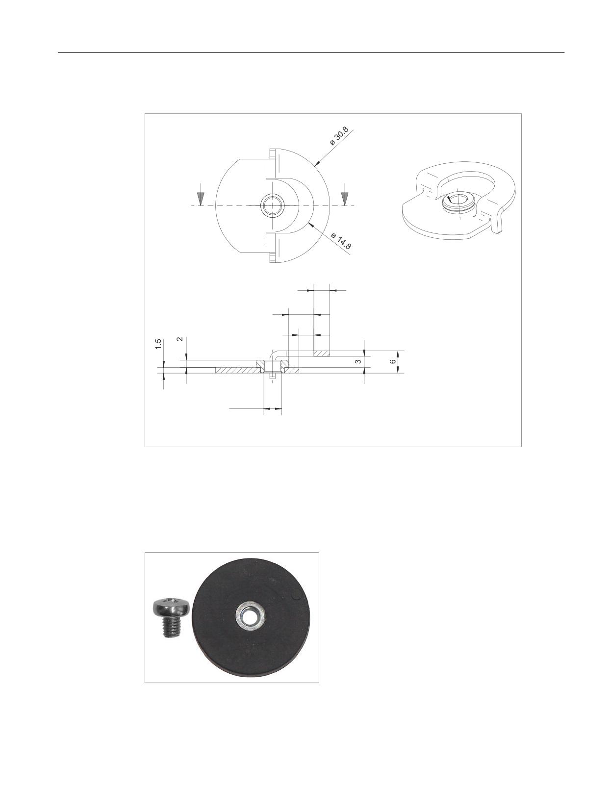
Dimension drawing
$
$
0
$$
Image 1-27 Dimension drawing of the HT 2 mounting bracket
1.9.3
Retaining magnet
The HT 2 can be mounted onto all sheet metal parts using the retaining magnets.
Image 1-28 HT 2 retaining magnet
Handheld units
Manual, 03/2016, 6FC5397-1AP40-5BA3
63
Handheld Terminal HT 2
1.9 Accessories
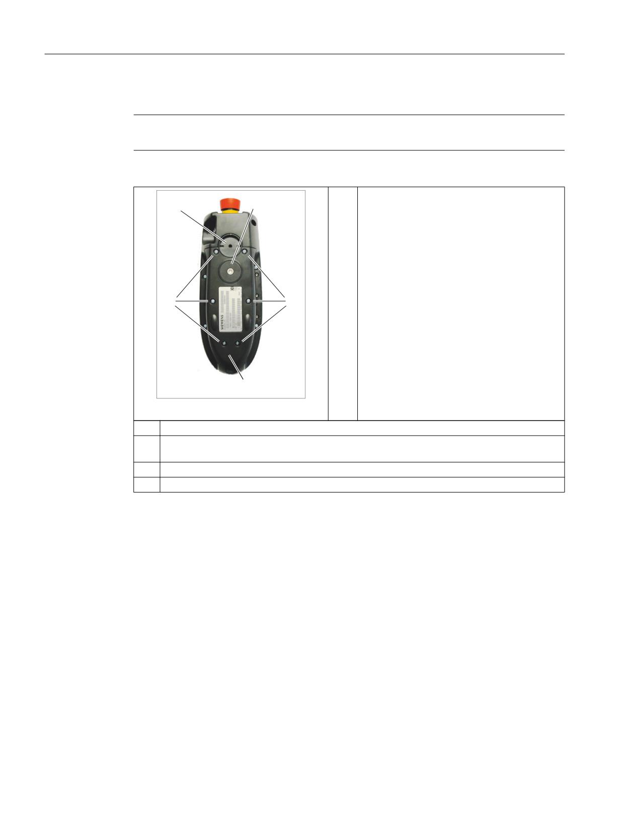
Mounting the retaining magnets
Note
A second magnet can be mounted at position (2) to increase the holding forces.
1.
Open the cable duct cover by unscrewing the six
PT screws approximately 1 cm.
To do this, use a crosstip size 2 screw driver.
(1)
Standard position retaining magnet (optional: Mounting bracket)
(2)
Standard position mounting bracket (optional: Retaining magnet)
A second retaining magnet can be used when required.
(3)
PT screws (4 x 20 mm)
(4)
Cable duct cover
Handheld units
64
Manual, 03/2016, 6FC5397-1AP40-5BA3
Handheld Terminal HT 2
1.9 Accessories
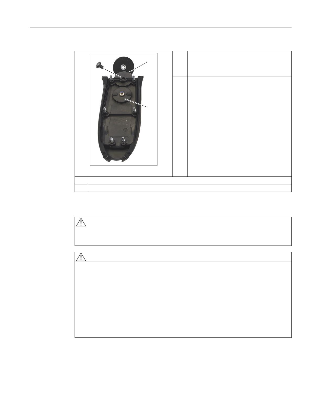
2.
Locate the retaining magnets under the cable
duct cover and retain them from the rear using
the screw.
To do this, use a slotted size 4 screwdriver.
3.
Re-attach the cable duct cover of the HT 2.
Ensure that the tightening torque does not ex-
ceed max. 0.4 - 0.5 Nm.
(1)
Retaining magnet with retaining screw
(2)
Retaining magnet mounted
Working with retaining magnets
CAUTION
Danger of injury from flying sparks
Do not install the magnets in hazardous locations as they can cause arcing and sparking.
WARNING
Danger of death due to strong magnetic fields
Even at a considerable distance apart, magnets can be attracted to one another, repel one
another or splitter when they collide. This involves strong forces.
This is the reason that you should avoid that magnets collide and work with the appropriate
protection in order to prevent skin crushing and other injuries.
Strong magnetic fields can destroy electronic or mechanical elements and devices.
This also applies to heart pacemakers.
Therefore observe the necessary safety clearances. Information on this is provided in the
documentation of the corresponding devices.
Carefully observe the appropriate packing regulations when shipping by air.
Handheld units
Manual, 03/2016, 6FC5397-1AP40-5BA3
65
Handheld Terminal HT 2
1.9 Accessories
1.9.4
Slide-in label
1.9.4.1
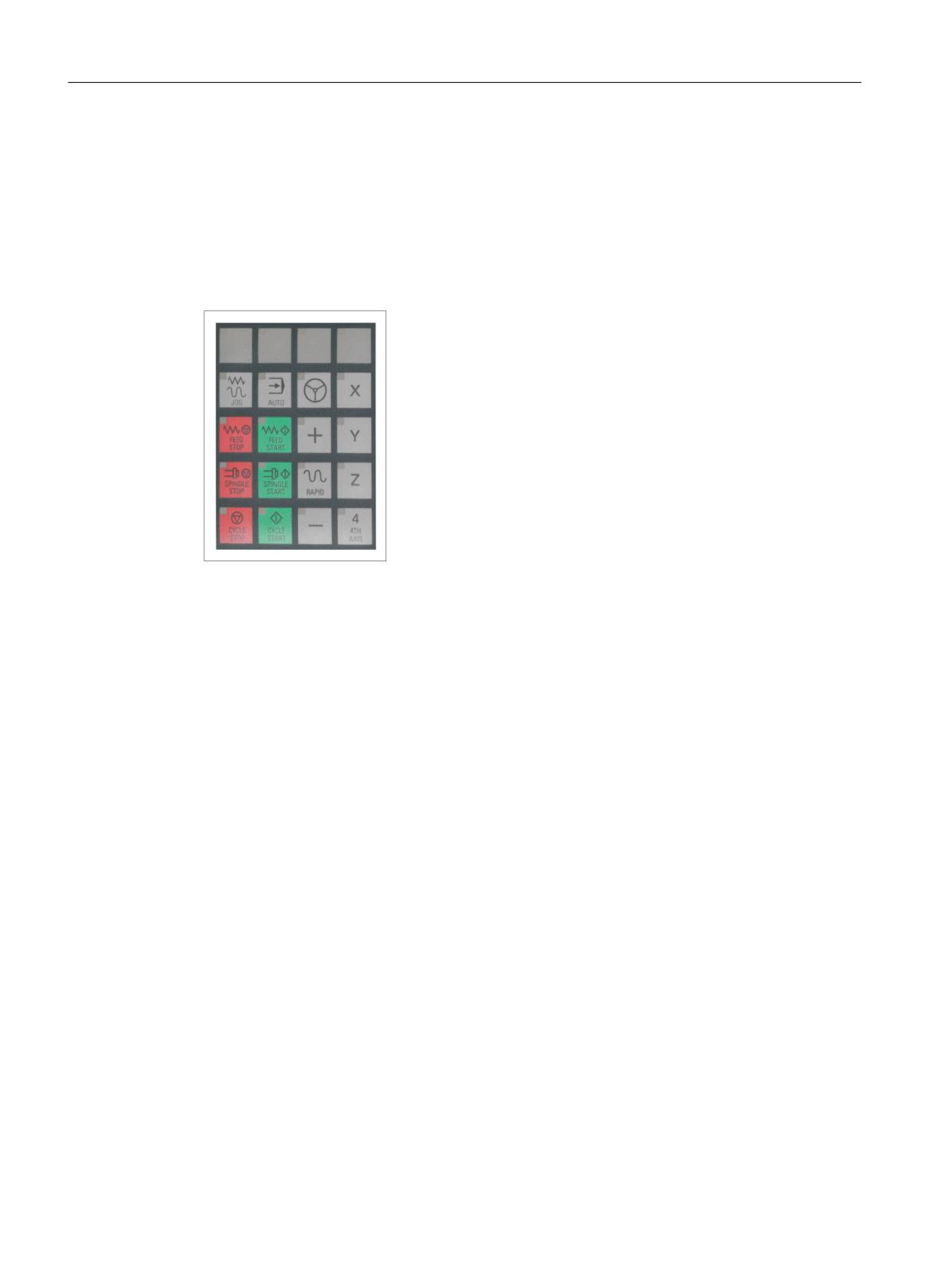
Labeling the slide-in labels
In the factory, the Handheld Terminal HT 2 is supplied with five horizontal slide-in labels.
With the exception of the slide-in label for the first row of keys, standard symbols for the
machine control are printed on the slide-in labels.
Image 1-29 HT2 slide-in labels
When requested, an accessory package with three blank slide-in labels can be ordered, so
that these strips can be printed with the key symbols according to your specifications (see
Section: "Accessories" → "Overview").
Handheld units
66
Manual, 03/2016, 6FC5397-1AP40-5BA3
Handheld Terminal HT 2
1.9 Accessories
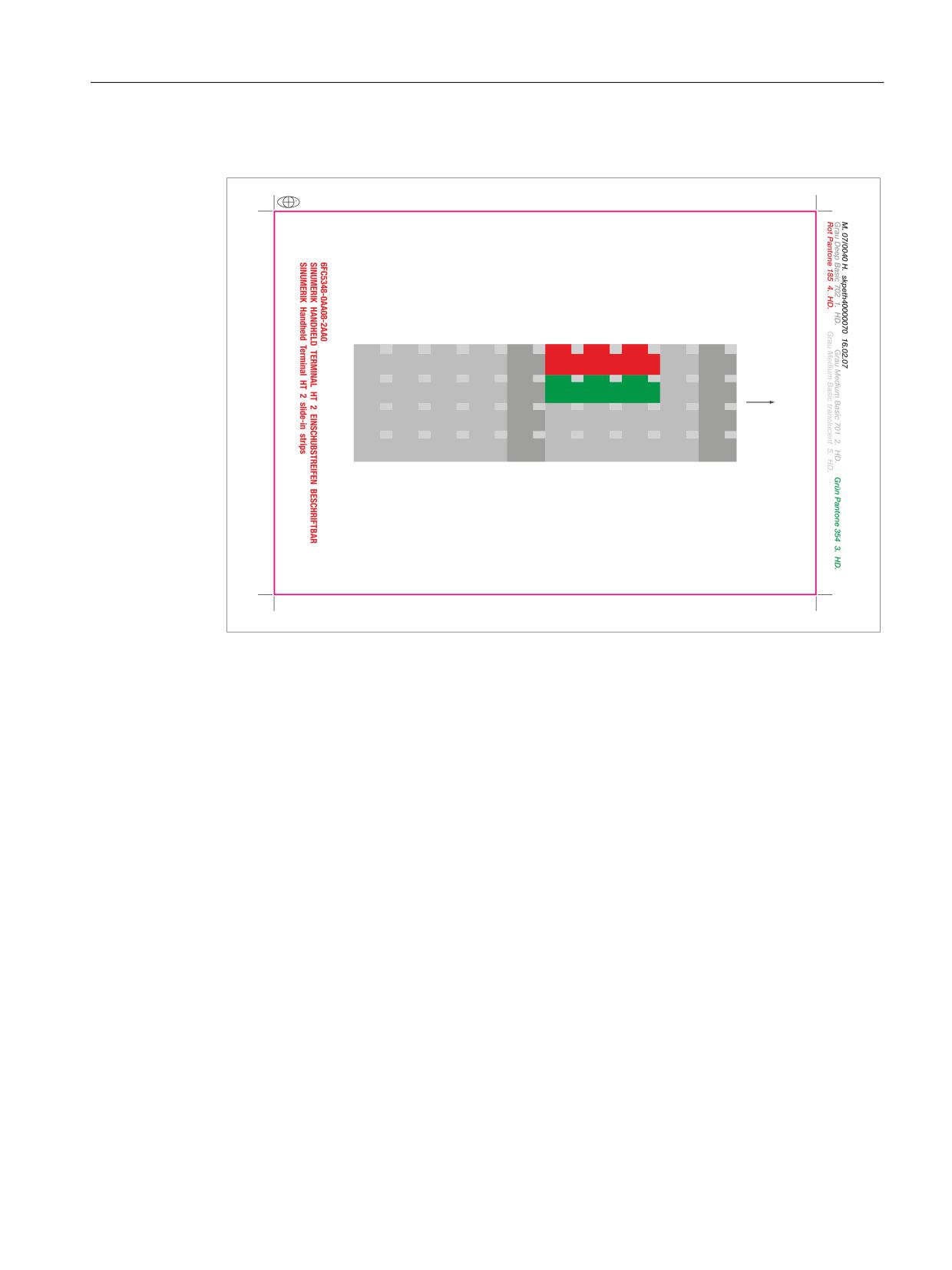
Files for printing the blank film
Image 1-30 Blank film HT 2 [printing direction (1)]
The DOConCD / Catalog NC 61 (CD enclosed) contains two files for printing the blank films:
● Template_HT2_13.doc
● Symbols_OP08T_13.doc
The file "Template_HT2_13.doc" is a template for the exact positioning of the symbols on the
printable film.
Handheld units
Manual, 03/2016, 6FC5397-1AP40-5BA3
67

Handheld Terminal HT 2
1.9 Accessories
Image 1-31 Template_HT2_13.doc (blank template for the film)
The "Symbols_OP08T_13.doc" file contains a broad range of key symbols.
An overview of these can be found via "Operator panels" > "OP 08T operator panel front" >
"Accessories" > "Labeling the slide-in labels".
Preparing slide-in labels
1. Open the files "Template_HT2_13.doc" and "Symbols_OP08T_13.doc" in MS Word.
2. Select a key symbol from the file "Symbols_OP08T_13.doc" by left-clicking.
3. Copy the desired symbol to the clipboard via "Edit" → "Copy" or "Ctrl + C"
4. Return to the template file "Template_HT2_13.doc"
5. Position the cursor before the insertion point in the desired table cell.
6. Insert the key symbol via "Edit" → "Paste" or "Ctrl + V".
7. To format the graphics, double click on the inserted symbol with the lefthand mouse key.
- Select the "size" tab and set the symbol height to 1.1 cm.
- Click on <OK> to accept the change.
8. Repeat steps 2. to 7. until you have inserted all the key symbols.
Handheld units
68
Manual, 03/2016, 6FC5397-1AP40-5BA3
Handheld Terminal HT 2
1.9 Accessories
Printing the slide-in labels
1. Place the blank film in the printing direction in the slot of your laser printer (see Fig.: "Blank
film HT 2").
2. Select "film" as the printable medium if your printer allows this setting.
3. Start the printing process using MS Word.
Note
For labeling the slide-in labels, HP Color Laser Jet film C2936A is used.
Make a test print on paper before you print on the film.
Allow the film to cool after printing so that the ink can dry.
4. Cut the slide-in labels out of the film along the edges (see Fig.: "Template_HT2_13.doc").
5. Round off the corners of the slide-in labels approx. 3 mm to facilitate insertion.
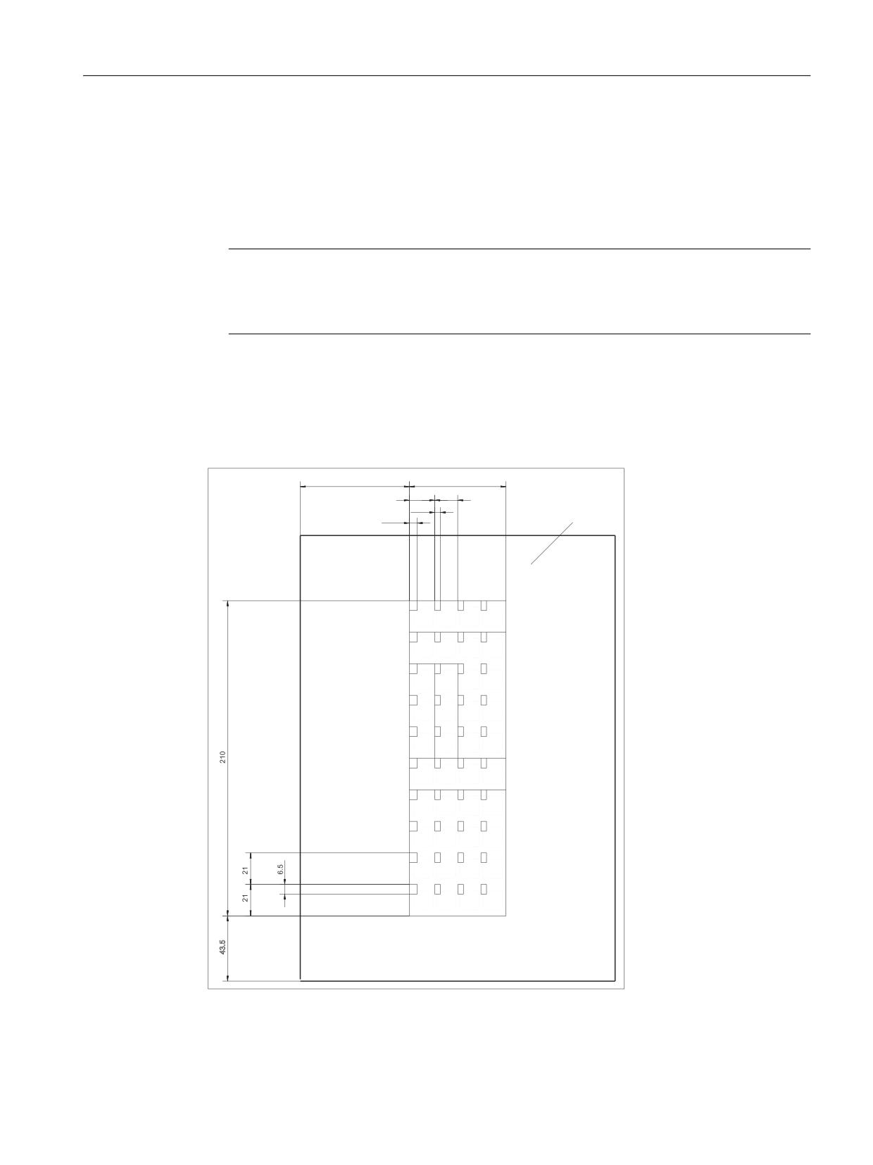
Dimension drawings
Image 1-32 Dimensions for slide-in labels
Handheld units
Manual, 03/2016, 6FC5397-1AP40-5BA3
69
Handheld Terminal HT 2
1.9 Accessories
Creating your own symbols
● Drawing in a vector program (e.g. Designer, Freehand, CorelDraw):
- Draw a 13 x 13 mm square, fill with the color white and give it an invisible border line.
- Place the symbol in the center of this square.
- Group the square and symbol together and add this group in the MS Word document
Template_HT2_13.doc.
● Drawing in an image editing program (e.g. Photoshop, Picture Publisher, Paint)
- Draw a square 13x13 mm (37x37 pixel), filled with the color white.
- Draw the symbol in the center of this square.
- Copy the symbol and the square together and add the group in the MS Word document
Template_HT2_13.doc.
1.9.4.2
Replacing the slide-in labels
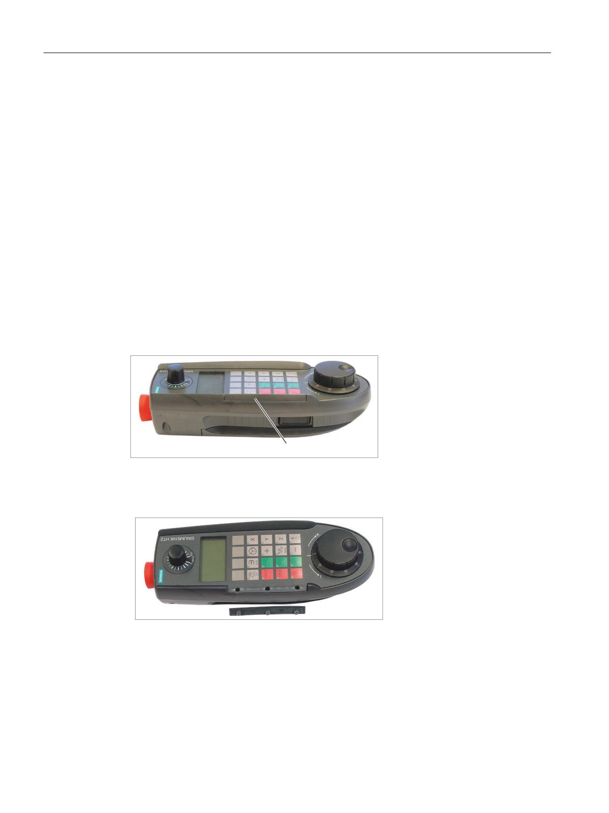
The slots to insert the slide-in labels are located under a cover on the lefthand side of the HT 2
that is integrated into the device design.
Image 1-33 Cover of the slide-in labels (1)
The retaining screws of the cover are accessible from the rear of the HT 2.
1.
Remove the three Phillips
screws (5x14) using a screw-
driver, size PH1.
2.
Remove the cover.
Handheld units
70
Manual, 03/2016, 6FC5397-1AP40-5BA3
Handheld Terminal HT 2
1.9 Accessories
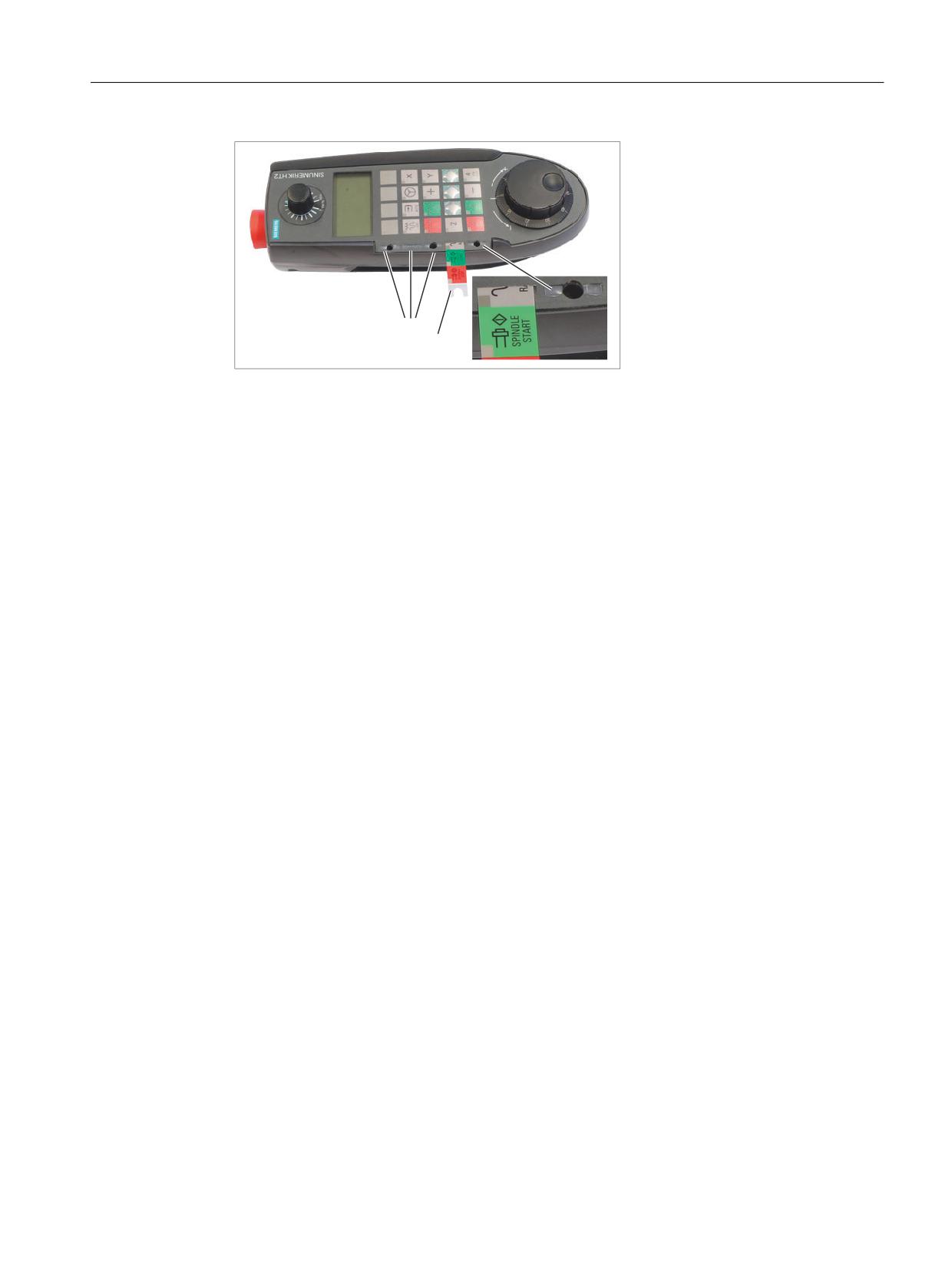
3.
Withdraw the required slide-in
label.
4.
Insert the new slide-in labels.
5.
Re-attach the cover and screw
it into place.
(1)
Slide-in labels inserted
(2)
Slide-in labels withdrawn
Handheld units
Manual, 03/2016, 6FC5397-1AP40-5BA3
71
Handheld Terminal HT 2
1.9 Accessories
Handheld units
72
Manual, 03/2016, 6FC5397-1AP40-5BA3

Handheld Terminal HT 8
2
2.1
Description
The HT 8 mobile handheld terminal combines the functions of an operator panel and a machine
control panel in one device, permitting complete operator control and monitoring of machines.
It can be used according to the principle of a thin client (also see "Operator panels", Chapter:
"Thin client unit") as a supplementary main operator panel or as a secondary control panel.
The optional touch pen with a holding loop permits easy operation of the touch screen, even
when operators are wearing gloves. Its safety concept permits working in the hazardous area
of the machine, which is necessary, for example, when teaching in.
Note
Siemens declares that this device complies with the requirements and other regulations of the
directives 2006/42/EC (machinery directive) and 2004/108/EC (EMC guideline).
The full declaration can be found on the Internet (https://support.industry.siemens.com/cs/
document/109476859?dti=0&lc=en-WW).
Features
● Operator control via touch screen and membrane keys
● Fully graphic 7.5" TFT color display
● Emergency Stop button and two enabling buttons for left-handed and right-handed
operators
● Easy hot swapping during operation (hot plug and play), without triggering the emergency
stop in combination with the PN Plus connection box and without an additional, manual
actuating element / keyswitch
The HT 8 can be safely kept and operated in a stationary manner in the wall holder (accessory).
Validity
The following description applies to the following components:
Designation
Features
Article number
HT 8
Enabling button, emergency stop button, override
6FC5403-0AA20-0AA1
rotary switch
HT 8
Enabling button, emergency stop button, override
6FC5403-0AA20-1AA1
rotary switch, handwheel
The safety-related accessories are marked in the "Accessories" section with a *).
Handheld units
Manual, 03/2016, 6FC5397-1AP40-5BA3
73
Handheld Terminal HT 8
2.1 Description
Function blocks
In the unit:
● PCB with CPU, memory
● Ethernet controller
Device front:
● LC display as touch screen
-
640 x 480 (VGA) Color TFT
– Inverter on board
●
52-key membrane keyboard
-
24 machine control keys
-
28 control keys (number pad, cursor pad, function keys)
● Emergency Stop button, 2-channel
● Rotary override switch (19 positions)
● Handwheel (optional)
Device rear:
●
2 enabling buttons (2-channel, 3-stage)
● Serial interfaces:
- HT 8 connection cable to terminal box / connection module
- USB interface (with dummy plugs)
● Power supply (+24 V)
Handheld units
74
Manual, 03/2016, 6FC5397-1AP40-5BA3
Handheld Terminal HT 8
2.2 Operator controls and indicators
2.2
Operator controls and indicators
2.2.1
View
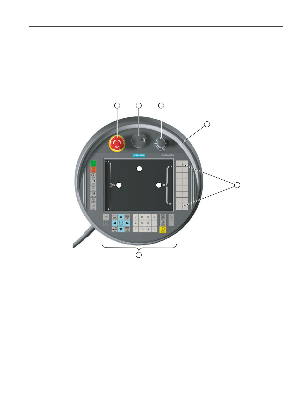
Front
① Emergency Stop button
② Handwheel
③ Rotary override switch
④ Protective collar
⑤ Customer keys (user-defined)
⑥ HMI control keys
⑦ Function keys machine control panel
⑧ Display / touch screen
⑨ Traversing keys
Image 2-1
User interface of the HT 8 with handwheel
Handheld units
Manual, 03/2016, 6FC5397-1AP40-5BA3
75
Handheld Terminal HT 8
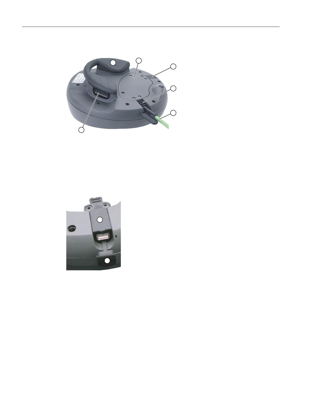
2.2 Operator controls and indicators
Rear
① Handle
② Cover
③ Connector with integrated USB connection
④ Sleeve for the connecting cable
⑤ Connecting cable
⑥ Enabling buttons (left and one right on the handle)
Image 2-2
Connections and operator controls at the rear of the HT 8
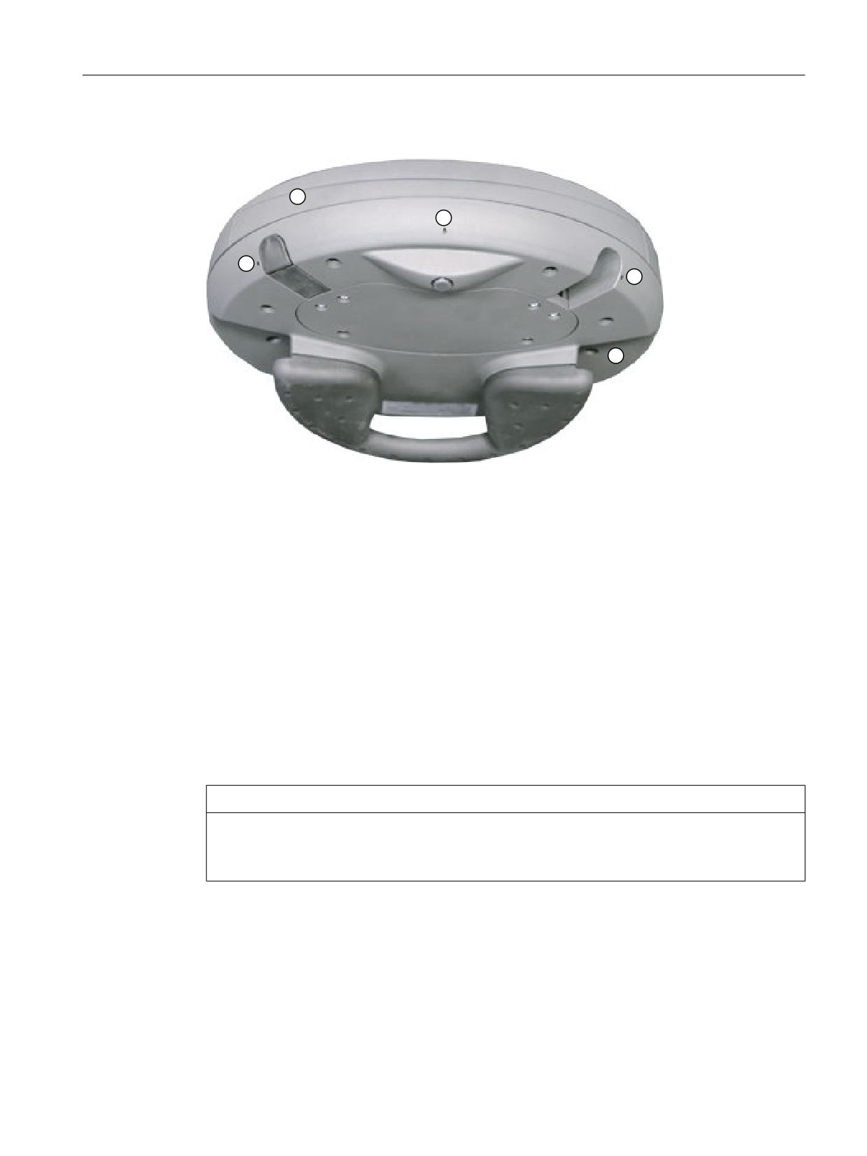
① Connector with integrated USB connection
② USB protective cap
Image 2-3
USB connection of the HT 8
Handheld units
76
Manual, 03/2016, 6FC5397-1AP40-5BA3
Handheld Terminal HT 8
2.2 Operator controls and indicators
Holes
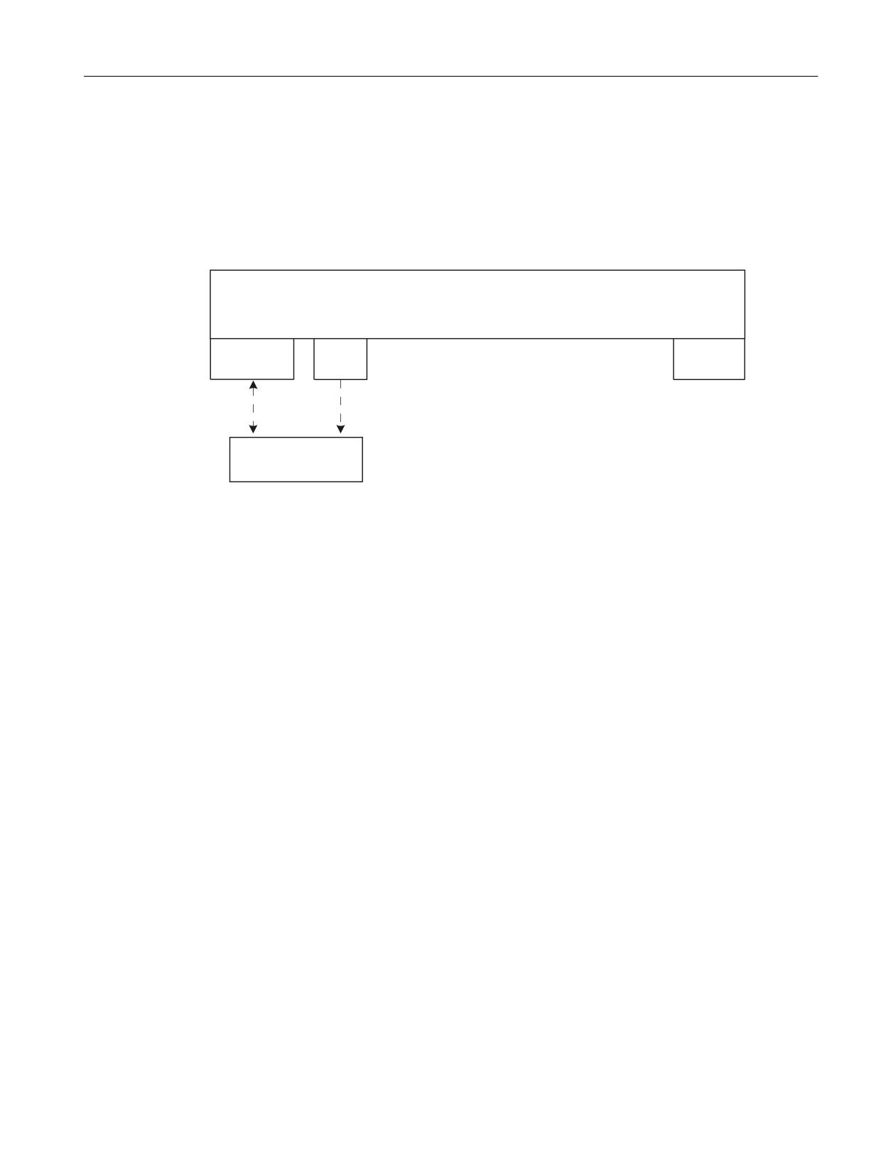
The HT 8 consists of a double-walled housing with upper shell ① and lower shell ③
On the lower shell, the HT 8 has three small holes ②. These drill-holes are attached for the
purpose of diverting the liquid that can penetrate into the space between the double-walled
housing if the malleable protective shroud on the upper shell is pushed through.
2.2.2
Description
Display / touch screen
The display has LED backg4round lighting.
All the application-specific functions are displayed on the touch-sensitive display. The
particular function is initiated by your finger or an optional touch pen at the appropriate location
in the display.
NOTICE
Damage to the display by pointed or hard objects
Do not touch the operating elements of the display with pointed or hard objects, as this can
damage it, sometimes beyond repair.
In order to achieve precise assignment by pixels, the touch-sensor must be calibrated and
adjusted to the touch screen.
Handheld units
Manual, 03/2016, 6FC5397-1AP40-5BA3
77

Handheld Terminal HT 8
2.2 Operator controls and indicators
Information for calibrating the touch screen of the HT 8 can be found in:
"General information and networking", Chapter: "Networking"
Note
Calibration of the touch sensor may also become necessary during operation, because the
resistance values of the touch membrane change when there is a temperature change.
Membrane keyboard
On the front of the HT8, 52 keys are arranged in several key blocks (see Image 2-1 User
interface of the HT 8 with handwheel (Page 75)).
NOTICE
Damage to the keys when using pointed or hard objects
Only use your fingers to touch the membrane keyboard and not sharp or hard objects, which
can damage or even destroy the keys. Further, please note that the touch pen is also not
suitable for using the membrane keyboard.
Function keys machine control panel
● Left: START, STOP, RESET, AUTO, JOG, TEACH, ALARM CANCEL
● Bottom: U (User button)
● Right: 2 x 6 traversing keys, 4 user keys (can be freely assigned)
HMI control keys
● The number pad contains the numbers 1-9, the decimal point and the minus sign
● The cursor pad is used to navigate on the screen.
● Seven keys for
- Input
- Menu change
- Switch-over of the softkey bars
- Help function
Emergency Stop button
The red mushroom-shaped head of the Emergency Stop button is provided with a yellow ring.
Directly under the mushroom-shaped head, there is also a black ring which identifies the
position status of the Emergency Stop button.
State
Ring (black)
Visible
Not visible
Emergency Stop button
Not pressed
Pressed
Handheld units
78
Manual, 03/2016, 6FC5397-1AP40-5BA3

Handheld Terminal HT 8
2.2 Operator controls and indicators
If an emergency stop is triggered, the button locks into place.
If the button is locked into place, it can be unlocked by rotating it to the right.
Emergency Stop button
Press the red button in emergencies when
∎
people are at risk,
∎
there is the danger of machines or the workpiece being
damaged.
As a rule, when operating the Emergency Stop button, all
drives are brought to a standstill with max. braking torque.
Machine manufacturer
For other responses to the Emergency Stop:
Refer to the machine tool manufacturer's instructions!
The signals are sent via the connecting cable to the terminal box or the connection module
and are available for further wiring.
Rotary override switch
The rotary override switch of the HT 8 has 19 positions.
The evaluation scale (0 to max.) is specified by the machine's manufacture in the form of
machine data.
Enabling button
The HT 8 has two enabling buttons that are logically grouped.
This allows the enabling function to be triggered by either the left or the right hand during
normal operation.
The enabling buttons are configured as 2-channel, 3-position switches for the following button
positions:
● Released (no activation)
● Enabling (center position) - enabling for channel 1 and 2 is on the same switch.
● Panic (completely pushed through)
Note
Monitoring the enabling function
● The enabling duration is monitored to avoid that the enabling button is permanently
bypassed. The enabling outputs are opened after max. 30 min permanent enabling. The
enabling outputs are only closed again after first releasing the enabling button and then
actuating it again. The enabling time of 30 min can be extended by switching to the second
enabling button before the 30 min expires.
● The system checks the synchronism of the two enabling button circuits of the mechanical
enabling button. The two enabling button circuits (of the button) must be closed within 2
seconds. As a consequence, it is not possible to actuate just one enabling circuit and
therefore provoke a fault.
Handheld units
Manual, 03/2016, 6FC5397-1AP40-5BA3
79

Handheld Terminal HT 8
2.2 Operator controls and indicators
The signals are sent via the connecting cable to the terminal box or the connection module
and are available for further wiring.
Connection examples of the enabling and emergency stop button can be found in Chapter:
"HT 2", Section: "Connections" → "Connection examples of enabling button and emergency
stop button"
Handwheel
The HT 8 is available with a handwheel.
The handwheel operates with 50 pulses/revolution.
HT 8 operated with the handwheel
An HT 8 with a handwheel behaves in the same way as an MCP 483C PN (in Ethernet mode)
with a handwheel. The handwheel pulses are transferred via Ethernet to the NCK using the
HT 8 MCP process image.
NOTICE
Lack of care for traversing can cause damage to the tool/workpiece
The increments per revolution for a handwheel on a mobile HT 8 amount to 50 increments/
revolution; for a stationary unit, it is 100 increments/revolution. A different length of the
traverse path results from this difference.
2.2.3
Screen brightness control
If a screen with high contrast is displayed unchanged for longer than 1 hour, the screen
brightness control must be activated (screen switched dark) in order to protect the TFT display
against a phenomenon known as "burn-in" of the last displayed screen.
For more information see:
● IM9 Commissioning Manual SINUMERIK Operate
● IM4 HMI-Advanced Commissioning Manual
NOTICE
You may do irreversible damage to your TFT display if the screen brightness control is
not activated.
Handheld units
80
Manual, 03/2016, 6FC5397-1AP40-5BA3
Handheld Terminal HT 8
2.3 interfaces
2.3
interfaces
2.3.1
Overview
The following diagram shows the connection options at the HT 8.
+7
0DLQERDUG
;
;
;
9ROW
(PHUJHQF\ 6WRS
86%
EXWWRQ
(WKHUQHW
VRFNHW
(QDEOLQJ EXWWRQ
&RQQHFWLQJ FDEOH
7HUPLQDO ER[
&RQQHFWLRQ PRGXOH
033
Image 2-4
Block diagram of HT 8 interfaces
2.3.2
Description
Signal type
B
Bi-directional signal
O
Signal output
V
Supply voltage
I
Signal input
VI
Voltage input
VO
Voltage output
K
Contact
X3: Ethernet connection
The Ethernet interface is compatible to the 10/100/1000BASE-T IEEE 802.3 standard, without
crossover function.
Connector designa-
X3
tion:
Connector type:
8-pole RJ45-socket with interlock (above)
Pin assignment
The pin assignment corresponds to the standard, see "General infor-
mation and networking" → "Connecting".
Handheld units
Manual, 03/2016, 6FC5397-1AP40-5BA3
81
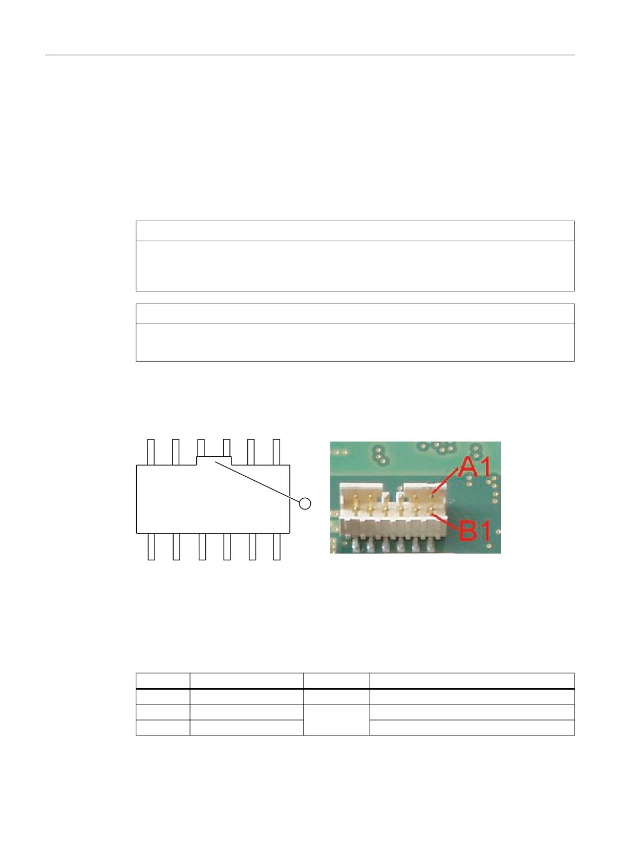
Handheld Terminal HT 8
2.3 interfaces
X5: USB interface
The USB interface corresponds to the USB 1.1 specification with full speed data rate.
Connector designa-
X5
tion:
Connector type:
Type A socket
Pin assignment
The pin assignment corresponds to the standard, see "General infor-
mation and networking" → "Connecting".
NOTICE
Damage to the plug by missing protective cap
Replace the USB connector if its protective cap is torn, because in this case, the connector
is no longer protected from dirt.
NOTICE
Damage to the inserted USB FlashDrive should the HT 8 fall
A plugged-in USB FlashDrive can be damaged or broken off if the device falls.
X51: Connection of the safety signals, power supply
$
$
$
$
$
$
%
%
%
%
%
%
① Recess
Connector designa-
X 51
tion:
Connector type:
12-pole connector plug with coding and locking
Pin
Signal
Signal type
Meaning
A1
IDENT_P
-
Box ID transfer +
A2
ENABLE 2+
Enabling button channel 2, digital
I
A3
ENABLE 1+
Enabling button channel 1, digital
Handheld units
82
Manual, 03/2016, 6FC5397-1AP40-5BA3
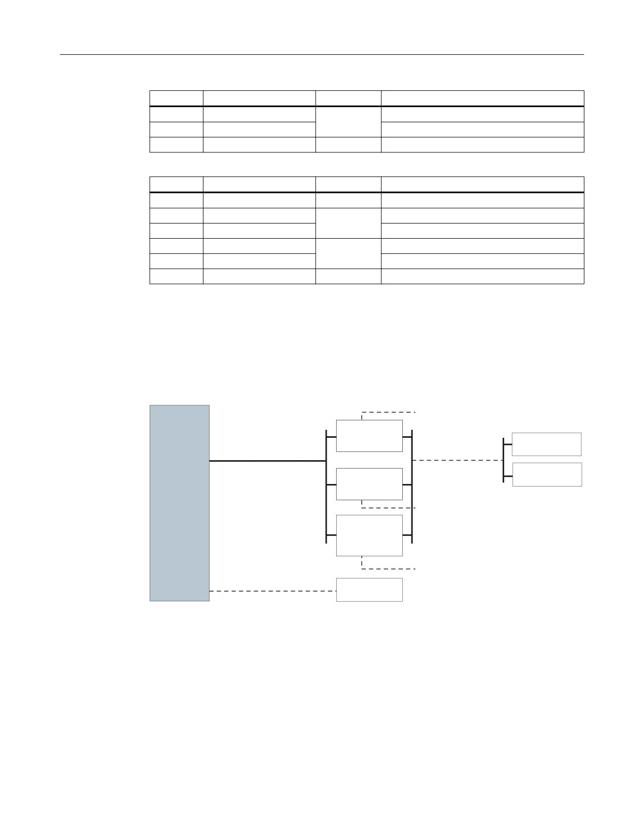
Handheld Terminal HT 8
2.4 Connecting
Pin
Signal
Signal type
Meaning
A4
STOP -13
Emerg. Stop circuit 2
K
A5
STOP -23
Emerg. Stop circuit 1
A6
P24
VI
+24 V power supply
Pin
Signal
Signal type
Meaning
B1
IDENT_N
-
Box ID transfer -
B2
ENABLE 2-
Enabling button channel 2, digital
O
B3
ENABLE 1-
Enabling button channel 1, digital
B4
STOP -14
Emerg. Stop circuit 2
K
B5
STOP -24
Emerg. Stop circuit 1
B6
M24
VI
External ground
2.4
Connecting
2.4.1
Overview
Article no.
Emergency stop / enabling circuit
SINUMERIK
Prefabricated cable
Handheld
Terminal
Connection box
PN Basic /
HT 8
SINUMERIK
PN Plus
PCU 50.5
6XV1440-4B...
Ethernet cable
or
6FC5348-0AA08-3AA0
SINUMERIK
Connection
NCU 7x0.3 PN
module
Basic PN
or
Emergency stop / enabling circuit
SINUMERIK
MPP 310 IEH/
MPP 483 IEH/
MPP 483 HTC
Emergency stop / enabling circuit
USB
interface
Image 2-5
Connection overview HT 8
The HT 8 is designed for communication in an Ethernet network. The following connection
options are available:
● PN Basic terminal box/PN Plus terminal box
● PN Basic connection module (for control cabinet installation) or
● MPP 310 IEH / MPP 483 IEH / MPP 483 HTC
Handheld units
Manual, 03/2016, 6FC5397-1AP40-5BA3
83
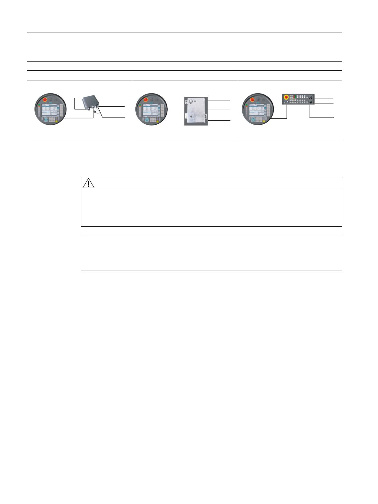
Handheld Terminal HT 8
2.4 Connecting
HT 8 with
PN Basic/PN Plus terminal box
PN Basic connection module
MPP 483 HTC
(WKHUQHW
(WKHUQHW
(WKHUQHW
(WKHUQHW
(WKHUQHW
(WKHUQHW
(WKHUQHW
6DIHW\
6DIHW\
6DIHW\
VLJQDOV
VLJQDOV
VLJQDOV
(WKHUQHW
(WKHUQHW
Connection via the PN Plus terminal box allows quick connection and disconnection during
machine operation without an emergency stop being triggered.
If no HT 8 is connected, observe the following:
WARNING
Danger of death resulting from improper access
● After disconnection, the HT 8 must be locked away.
● Emergency Stop buttons that are inactive must not be identified as such or must be
inaccessible. This is to prevent the emergency stop button from being used inadvertently.
Note
An example of TCU and MCP xxx PN as well as optionally an HT 8 or HT 2 on a PN box / PN
module can be found in Chapter: "HT 2", Section: "Commissioning" → "Application example of
HT8 and HT 2 in mixed operation".
Handheld units
84
Manual, 03/2016, 6FC5397-1AP40-5BA3
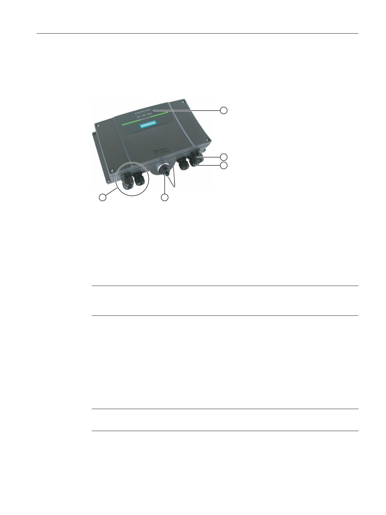
Handheld Terminal HT 8
2.4 Connecting
2.4.2
Terminal Box PN
2.4.2.1
Description
① LED displays for the communication
② Screwed joint for power supply cable and shield
③ Screwed joint for cable with safety signals and enabling button signals and for PLC accompa-
nying signals
④ Connecting socket for the connector plug of the connecting cable (covered with blanking cover)
⑤ Screwed joint for process data cables (Ethernet)
Image 2-6
View of the PN terminal box
Note
Degree of protection IP65 at the terminal box is ensured with plugged-in HT 8 or plugged-in
dummy cap.
The PN terminal box is available in two versions.
● PN Basic terminal box
The PN Basic terminal box can be used if no hot-plug capability is required. The Emergency
Stop circuit can be overridden here by external mechanisms.
● PN Plus terminal box
The PN Plus terminal box features hot-plug capability. This means that it is possible to
connect and disconnect during operation without any disruption.
The emergency stop circuit is automatically maintained during the switching of connectors.
Note
The exterior of the PN terminal box versions only differs in terms of what is printed on the side.
The terminal boxes feature two rotary coding switches (S1 and S2) so that a unique ID can be
set for the purpose of station identification. See Chapter interfaces (Page 89).
Handheld units
Manual, 03/2016, 6FC5397-1AP40-5BA3
85
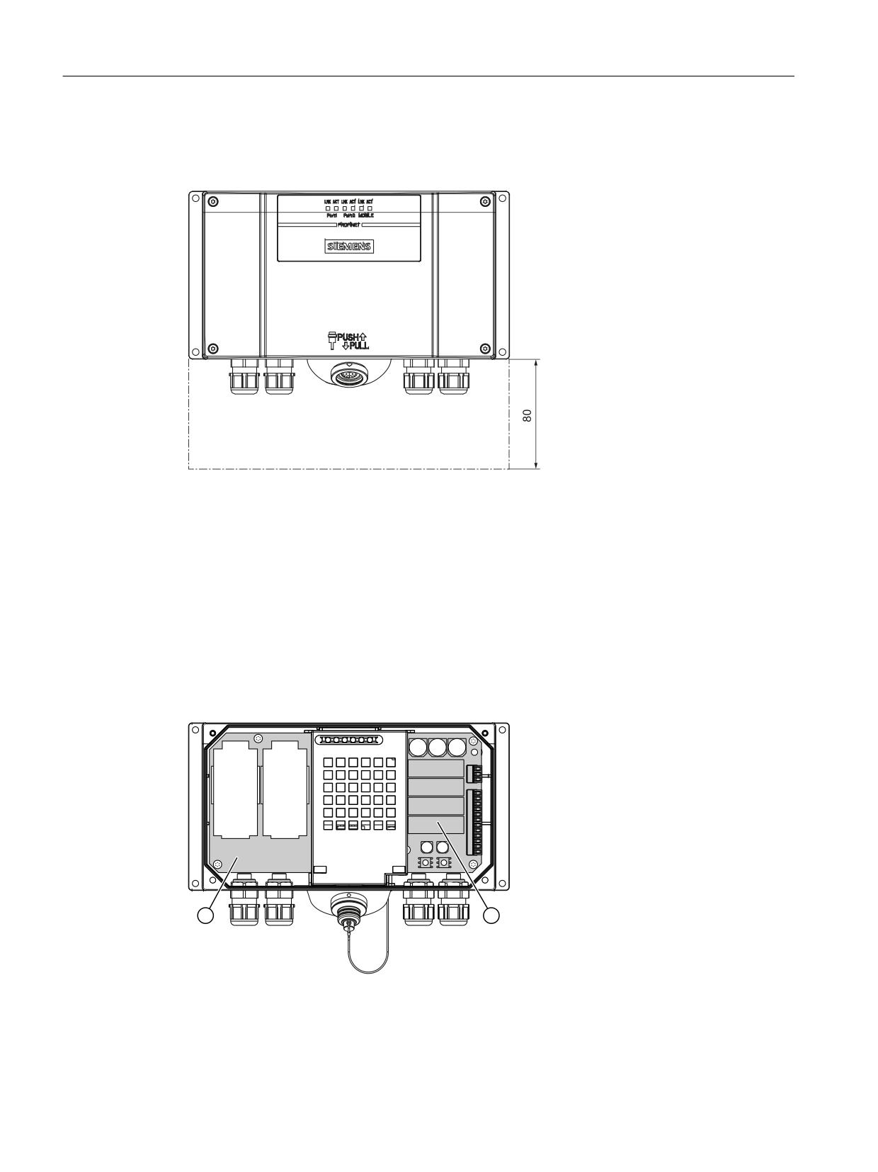
Handheld Terminal HT 8
2.4 Connecting
Clearance
The following clearances are required around the PN terminal box:
Additional references
You can find a detailed description in the operating instructions (compact) of the Mobile Panel
177 HMI device (WinCC flexible):
2.4.2.2
PN Plus terminal box
The PN Plus terminal box differs from a PN Basic terminal box in that it has four relays mounted
on the board.
① Board
② Relays
Image 2-7
Inner view of the PN Plus terminal box
Handheld units
86
Manual, 03/2016, 6FC5397-1AP40-5BA3
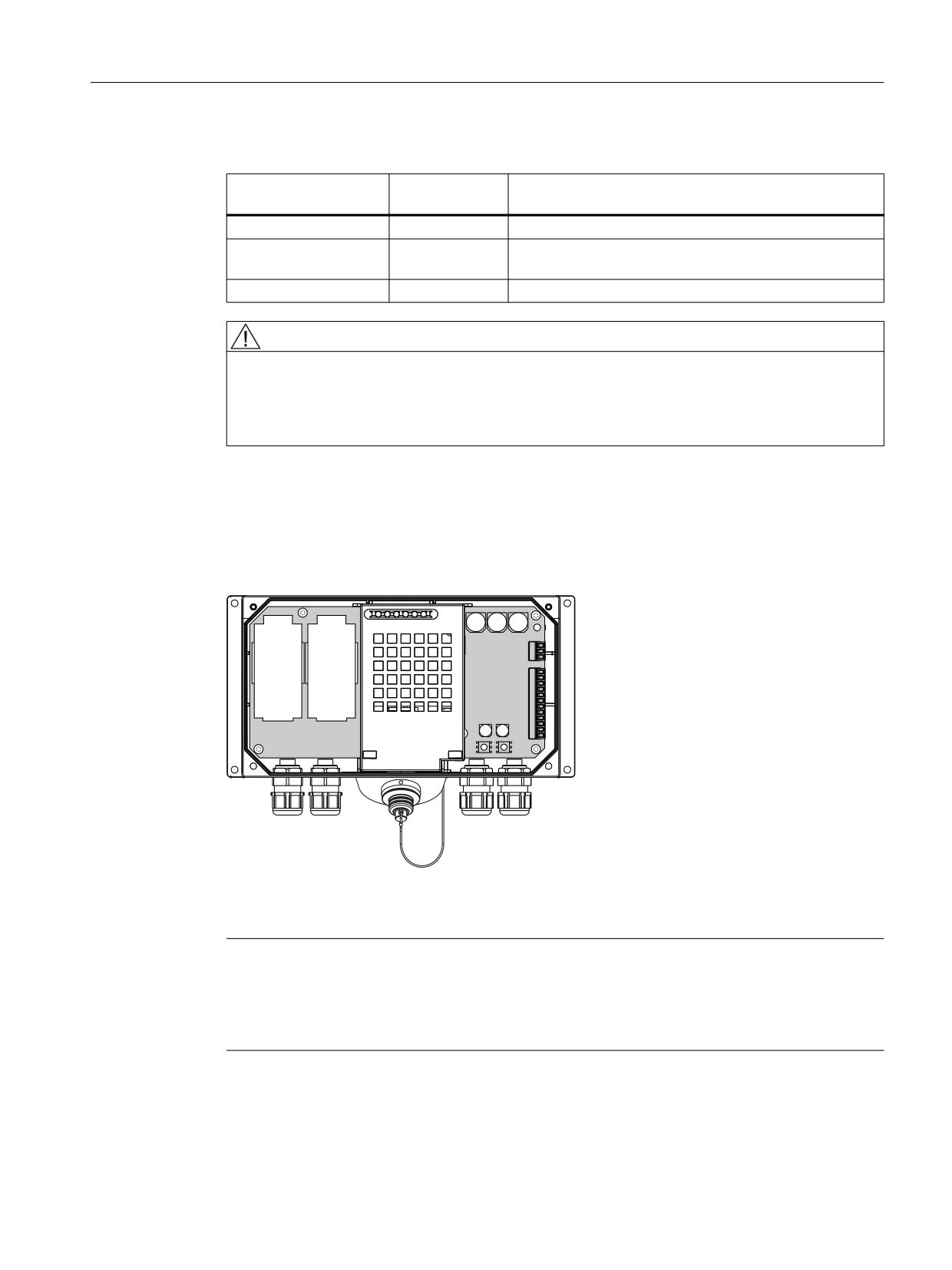
Handheld Terminal HT 8
2.4 Connecting
Switching states of the emergency stop circuit
HT 8
Emergency
Switching status, emergency stop circuit
Stop button
Connected
Not pressed
Emergency Stop circuit in the terminal box remains closed.
Connected
Pressed
The emergency stop circuit in the terminal box is open.
The system to be monitored is stopped.
Not connected
-
Emergency Stop circuit in the terminal box remains closed.
WARNING
Danger of death resulting from the inadvertent disconnection of the HT 8
If you disconnect the HT 8 from the PN Plus terminal box, the emergency stop circuit is closed,
thereby clearing the stop state of the system to be monitored. This occurs irrespective of
whether the emergency stop button has been pressed on the HT 8.
2.4.2.3
PN Basic terminal box
In contrast to the PN Plus terminal box, the "Stop loop through" function is not implemented
on the PN Basic terminal box. Relays are so not required.
Image 2-8
PN Basic terminal box
Note
The emergency stop circuit is controlled via the emergency stop button when the HT 8 is
connected. If the connecting cable of the HT 8 is disconnected from the PN Basic terminal
box, the emergency stop circuit is interrupted. This leads to a safe machine stop or an
Emergency Stop of the system to be monitored.
Handheld units
Manual, 03/2016, 6FC5397-1AP40-5BA3
87
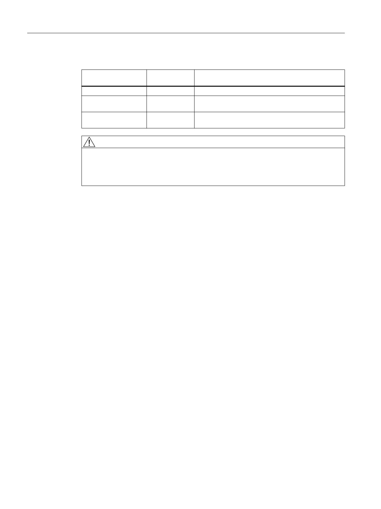
Handheld Terminal HT 8
2.4 Connecting
Switching states of the emergency stop circuit
HT 8
Emergency
Switching status, emergency stop circuit
Stop button
Connected
Not pressed
Emergency Stop circuit in the terminal box remains closed.
Connected
Pressed
The emergency stop circuit in the terminal box is open.
The system to be monitored is stopped.
Not connected
-
The emergency stop circuit in the terminal box is open.
The system to be monitored is stopped.
WARNING
Danger of death resulting from the premature emergency stop unlocking
If you have shut down the system to be monitored, you can only release the emergency stop
button or put the system to be monitored back into operation if the condition that triggered
the emergency stop function has been corrected and a safe restart is carried out.
2.4.2.4
Interfaces
Information about the interface assignment on the PN terminal box can be found in the
“Handheld Terminal HT 2" manual under “Connecting" → “Terminal Box PN" → “Interface
assignment on the PN Plus terminal box"connection.
See also
Interface assignment on the PN Plus terminal box (Page 18)
Handheld units
88
Manual, 03/2016, 6FC5397-1AP40-5BA3
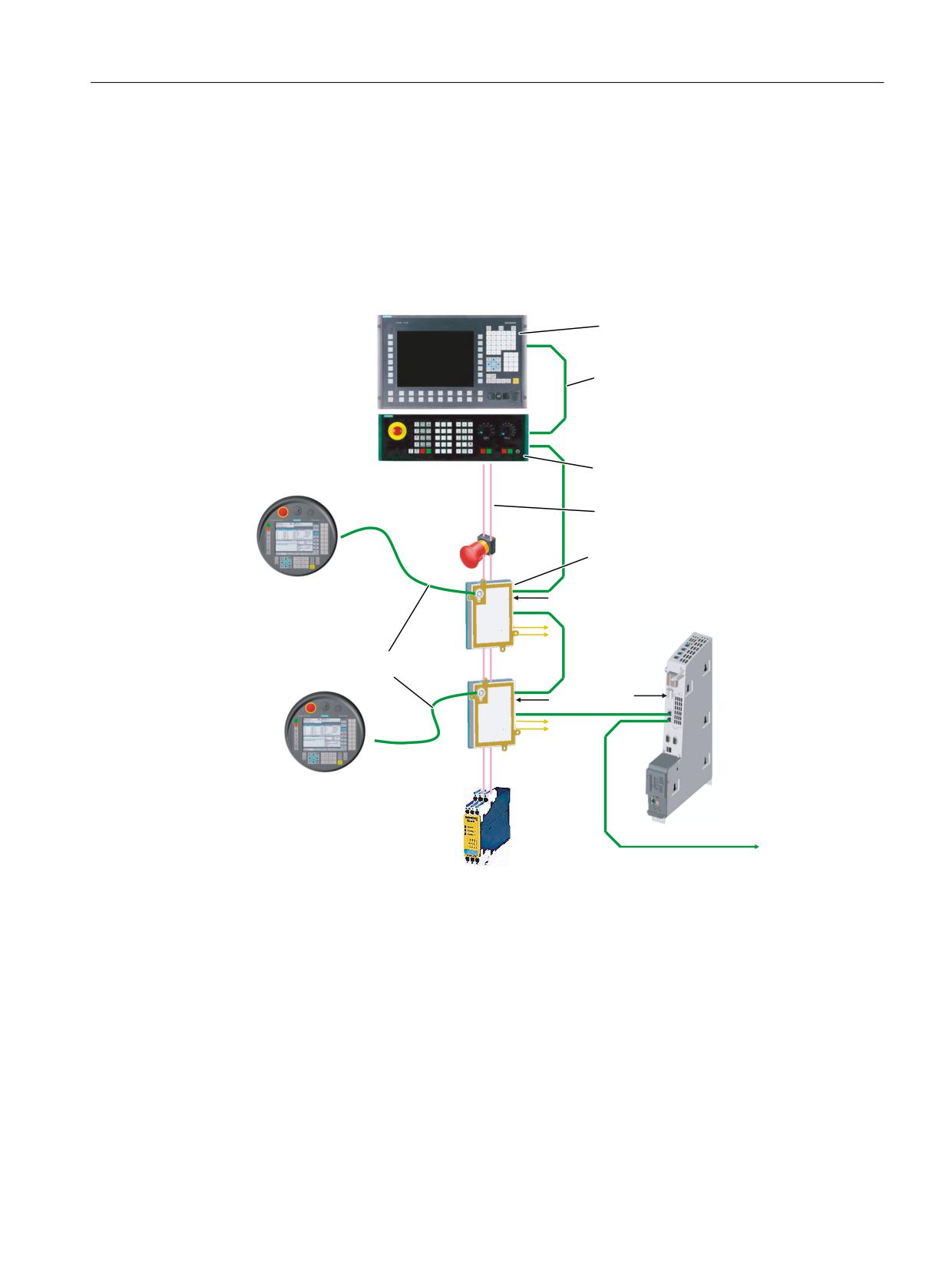
Handheld Terminal HT 8
2.4 Connecting
2.4.3
Connecting module Basic PN
2.4.3.1
Description
The connection module Basic PN was specially developed for installation in the control cabinet.
The terminating connector protrudes through the panel of the control cabinet so that the HT 8
can be connected from the outside.
2SHUDWRU SDQHO
6\VWHP QHWZRUN
0DFKLQH FRQWURO SDQHO
+7
(PHUJ 6WRS FLUFXLWV
31 %DVLF FRQQHFWLRQ PRGXOH
3
&RQQHFWLQJ FDEOH
+7
3
3
&RQWURO V\VWHPV
6WDWXV VLJQDOV
1&8
(PHUJHQF\ 6WRS
1&8
3DQHO SUHVHQW
1&8
6DIHW\
FRPELQDWLRQ
7.
)DFWRU\ QHWZRUN
Image 2-9
System configuration (example)
The connection module Basic PN is not hot plug-capable.
The HT 8 can either be connected directly to the NCU or to the PCU as thin client.
2.4.3.2
interfaces
The connector for the HT 8 is provided at the front of the PN connection module.
The other interfaces of the connection module are located at the rear:
Handheld units
Manual, 03/2016, 6FC5397-1AP40-5BA3
89
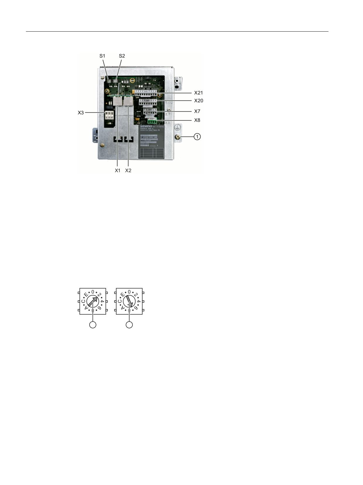
Handheld Terminal HT 8
2.4 Connecting
① Grounding screw M5 for potential equalization connection
Image 2-10 Rear of the Basic PN connection module
Setting the box ID
You can use rotary coding switches S1 and S2 to set a unique ID on any connection module
for station identification purposes.
Use a screwdriver to set the IDs.
The setting is entered in hexadecimal format. Values in the decimal format between 0 and 255
can be entered.
By way of an example, the figure below illustrates address 27H, which corresponds to decimal
address 39.
① Rotary coding switch for higher-order bits (S1)
② Rotary coding switch for lower-order bits (S2)
Image 2-11 Example for address "27H"
Connector pin assignments
Signal type:
I
Input
O
Output
B
Bi-directional signals
P
Potential
Handheld units
90
Manual, 03/2016, 6FC5397-1AP40-5BA3
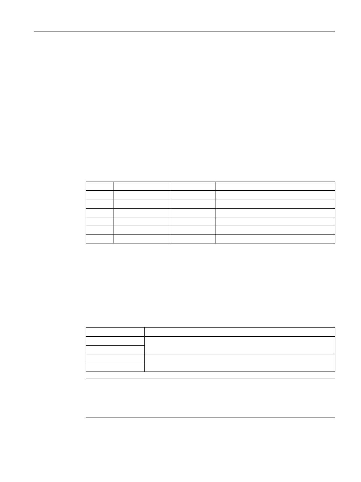
Handheld Terminal HT 8
2.4 Connecting
X1, X2: Ethernet interfaces
The pin assignment of the Ethernet interfaces X1, X2 can be found in "General information
and networking", Chapter: "Connecting", Section: "Pin assignment of the interfaces".
X3: Power supply
The pin assignment of the power supply interface X3 can be found in "General information and
networking", Chapter: "Connecting", Section: "Pin assignment of the interfaces".
X7: Panel Present
Connector designa-
X7
tion:
Connector type:
6-pin Phoenix terminal
Table 2-1
Assignment of the interface Panel Present X7
Pin
Signal name
Signal type
Meaning
1
PRES
O
"High": Panel (HT 8) plugged in
2
XCTL
O
"Low": EMER STOP button pressed 1)
3
XFAULT
O
"Low": Error in emergency stop electronics 1)
4
N.C.
-
Not connected
5
N.C.
-
Not connected
6
M
P
Ground
1)
Function not implemented in Basic PN variant, output is not switched to "High"
X8: Emergency Stop wiring terminal
Connector designa-
X8
tion:
Connector type:
4-pin Phoenix terminal
Table 2-2
Assignment of the emergency stop wiring terminal X8
Pin
Protective circuit
1
On-board jumper
between 1 and 2
2
3
On-board jumper
between 3 and 4
4
Note
Use this terminal for simple routing of the emergency stop cables, optional.
The connector is only used to assist looping through. The connected pins 1 and 2 as well as
3 and 4 have no additional function on the connection module.
Handheld units
Manual, 03/2016, 6FC5397-1AP40-5BA3
91