NB-series Programmable Terminals. NB-Designer OPERATION MANUAL (2026) - page 4
3 Functions of NB-Designer
2
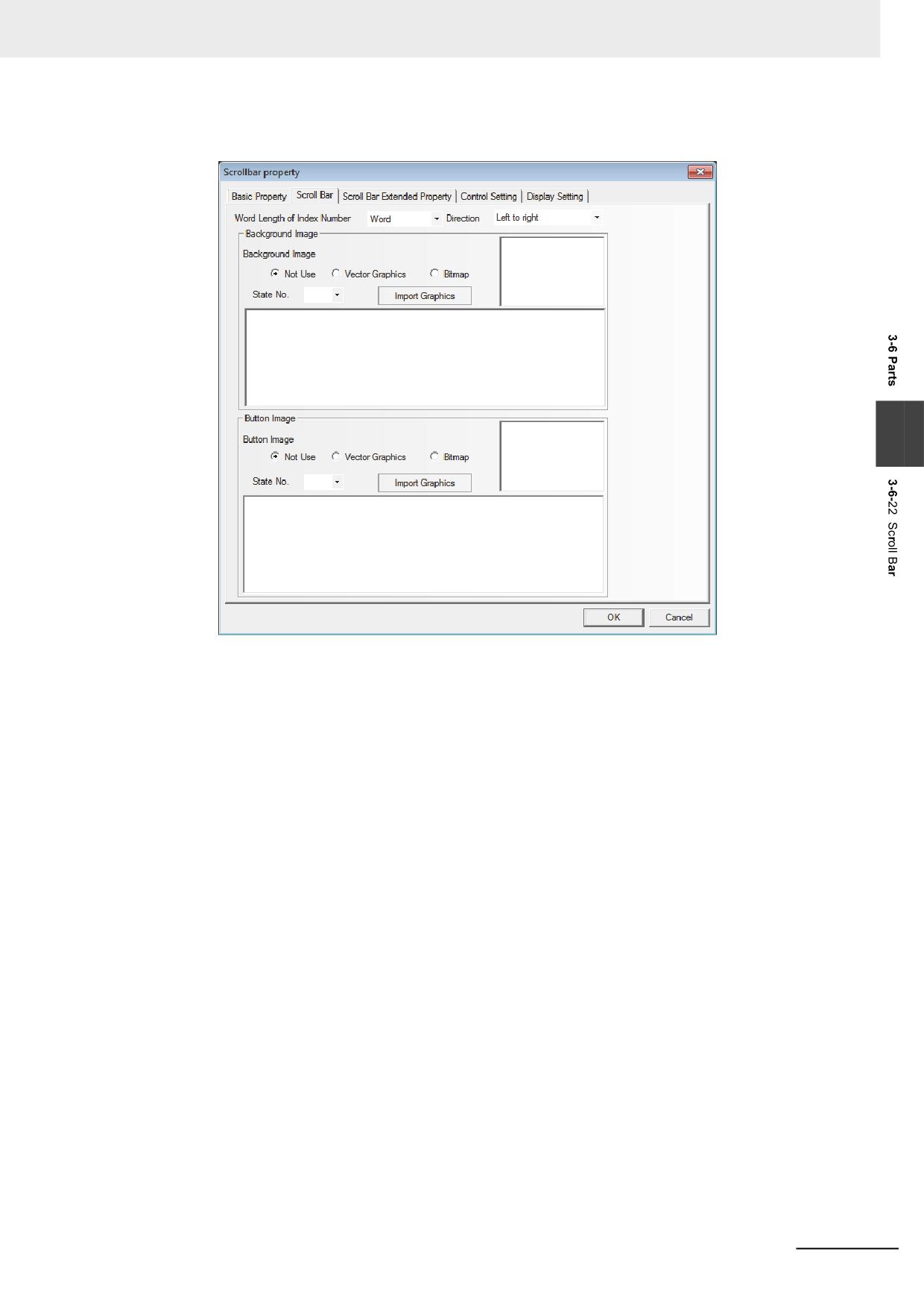
Go to the [Scroll Bar] tab.
3
Word Length of Index Number: Word and double-word are available.
Direction: Refers to the moving direction of the Scroll Bar, and it includes “Left To Right”,
“Right To Left”, “Up To Down” and “Down To Up”.
Background Image: Refers to the backg2round images used by the Scroll Bar. It includes “Not
Used”, “Vector Graphics” and “Bitmap”. If “Vector Graphics” or “Bitmap”
is selected, you can select the Vector Graphics or bitmap you want to
use in “Image”, and you can also select the State Number corresponding
to the Vector Graphics or bitmap mentioned above.
Button Image: Refers to the button images used by the Scroll Bar. It includes “Not Used”,
“Vector Graphics” and “Bitmap”. If “Vector Graphics” or “Bitmap” is selected,
you can select the Vector Graphics or bitmap you want to use in “Image”, and
you can also select the State Number corresponding to the Vector Graphics or
bitmap mentioned above.
NB-series Programmable Terminals NB-Designer Operation Manual(V106)
3-169
3 Functions of NB-Designer
3
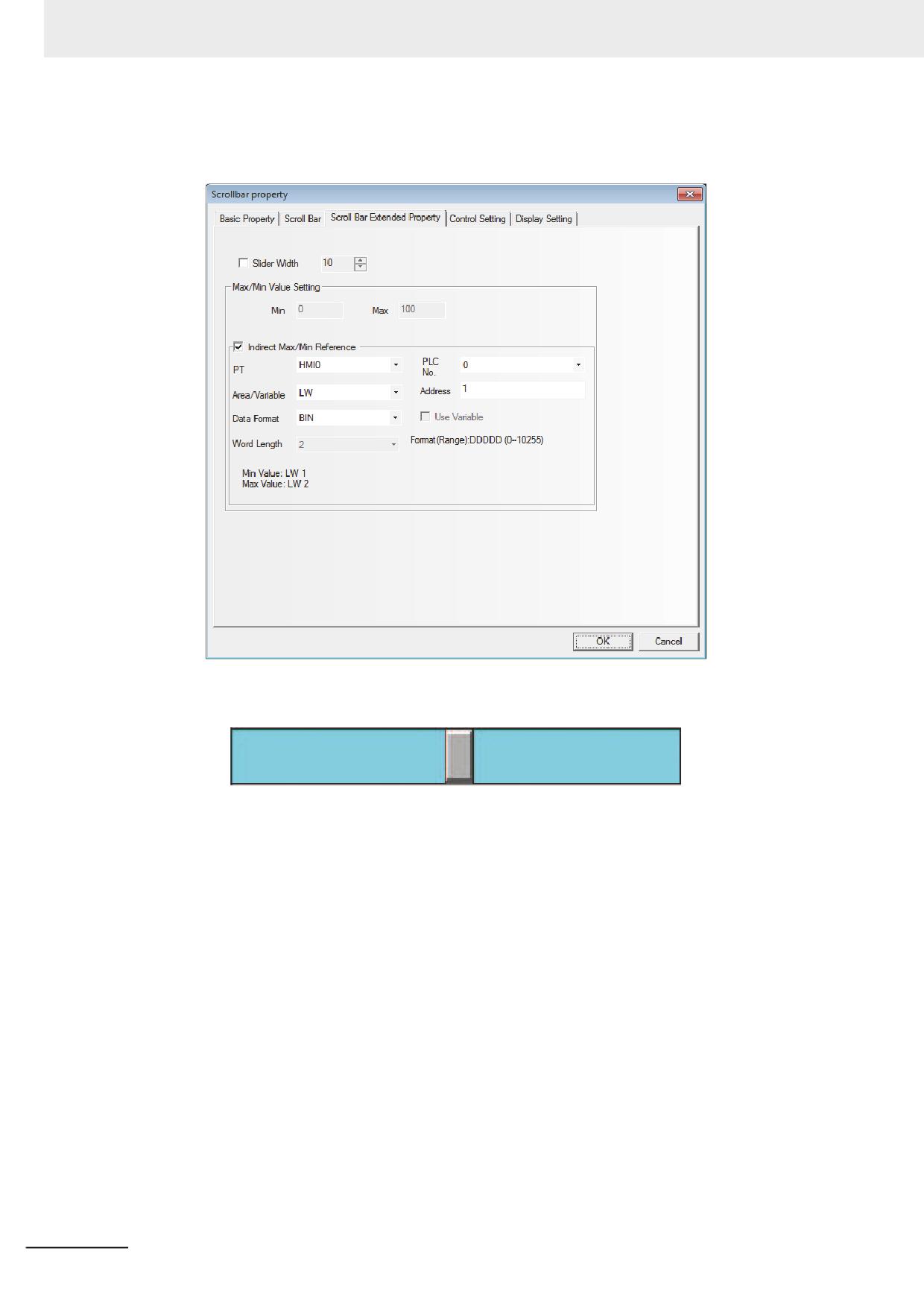
Go to the [Scroll Bar Extended Properties] tab and set the Slider Width and Indirect Max/Min
Reference.
Slider Width: Checking it means the slider width will be set by manual, and Not-checking it
means the slider width is 10 pixels by default.
Max/Min Value Setting:
Min: The lower limit of the Scroll Bar component is the starting browsing index value.
(-2147483648 to 2147483647 available)
Max: The upper limit of the Scroll Bar component is the maximum browsing index value.
(-2147483648 to 2147483647 available)
Indirect Max/Min Reference: Checking it means the starting browsing index value and the
maximum browsing index value of the Scroll Bar use the variables.
Assuming the address of the index memory is LW1, the addresses of the starting browsing
index value and the maximum browsing index value will be LW1 and LW2 respectively.
4
Press the [OK] button to complete the setup, and adjust the position and size of the Scroll Bar
component.
3-170
NB-series Programmable Terminals NB-Designer Operation Manual(V106)
3 Functions of NB-Designer
3-6-23
Event
Event component is used to display the event information registered in “Event Setting” and
whose current state satisfying the triggering conditions. The Event component will display triggered
event information one by one according to the time sequence of the triggered event. If the accurate
time needs to be displayed, the RTC must be used or the Time must be read from the PLC.
If multiple events are triggered, the events will be displayed in the order of descending or the latest
event will be at the top and the oldest event at the bottom.
In addition, if 1024 events or more are triggered, the event will be deleted in order from the oldest event.
When only a particular event is displayed, there may be the cases where the event suddenly disappears
because of the hidden events of which the number has significantly increased to exceed 1024.
When the event should be stored to the external memory, refer to 3-10-7 Event History Setting (Page 3-
3
321)
Process of adding one Event component
1
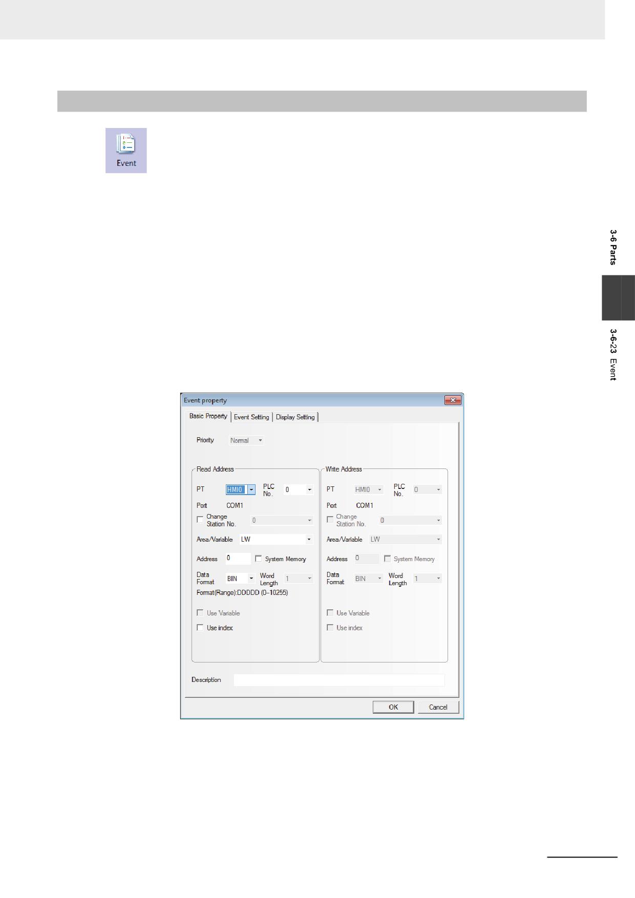
Press the Event component icon, drag it to the screen, then the [Basic Properties] dialog box of
the Event component will pop up.
Read Address: Refers to the address controlling the scroll of the event display. All the
information is classified according to the triggered time of the event, and the
new event is displayed on the top while the old event is displayed on the
bottom. For example, the value of the read address is N, the Nth event will be
displayed on the first line and the events on the lines with the smaller No. than
Nth line will be removed in the screen.
Address: Refers to the word address to support the controlling the scroll.
Word Length: Displaying the word length of read address (fixed as 1).
NB-series Programmable Terminals NB-Designer Operation Manual(V106)
3-171
3 Functions of NB-Designer
2
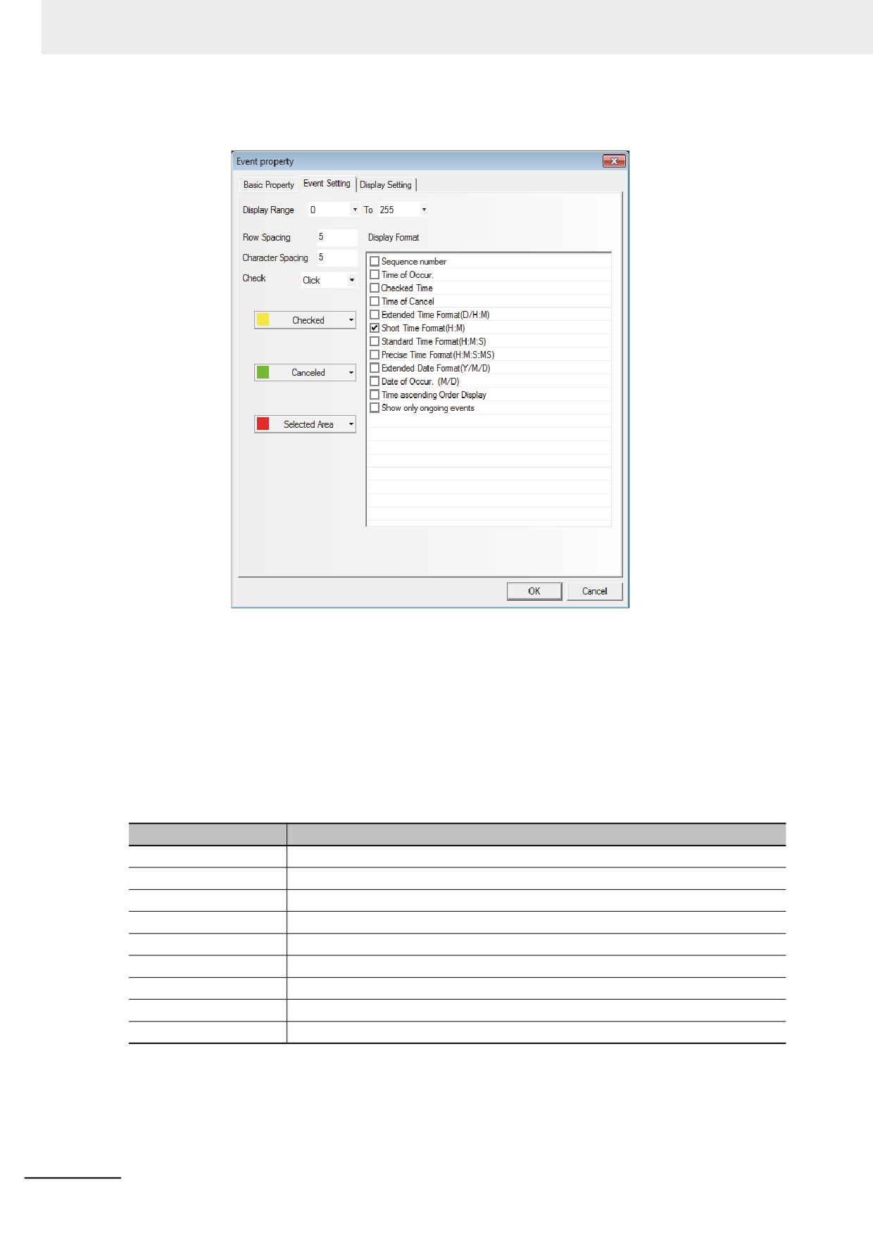
Go to the [Event Information] tab.
Row Spacing and Character Spacing: Refers to the distances between two neighboring lines
and characters. Graphic font ignores this setting.
Check: Includes the [Click] or [Double click].
Checked: Refers to the color after the event is confirmed.
Canceled: Refers to the color after the event is released.
Select Area: Indicates the color of the dotted line representing the selected area.
Display: Refers to the format of the Event Information Display. All the added contents (such as
Sequence No. and Event Trigger Time) are displayed in the front of the event
information.
Format Content
Descriptions
Sequence Number
Refers to the Event No. beginning from 0.
Time of Occur
The time when the event is triggered.
Checked Time
The time when the event is confirmed.
Time of Cancel
The time when the event is released. (i.e. returns to normal).
Extended Time Format
The time format is displayed as Day/Hour: Minute.
Short Time Format
The time format is displayed as Hour: Minute.
Standard Time Format
The time format is displayed as Hour: Minute: Second.
Precise Time Format
The time format is displayed as Hour: Minute: Second: Millisecond.
Extended Date Format
The data format is displayed as Year/Month/Date.
3-172
NB-series Programmable Terminals NB-Designer Operation Manual(V106)
3 Functions of NB-Designer
Format Content
Descriptions
Date of Occur
The data format is displayed as Month/Date.
Time ascending Order
The event is displayed in the ascending order.
Display
Show only ongoing
Only the event that is trigged is displayed here. And the released event will not be
events
displayed in the Event list. If this option isn’t checked, the events occurred before
but return to normal will still be displayed in the event list unless the event list is
cleared.
Date of
Time of
Checked
Time of
Event
No.
Occur
Occur.
Time
Cancel
content
3
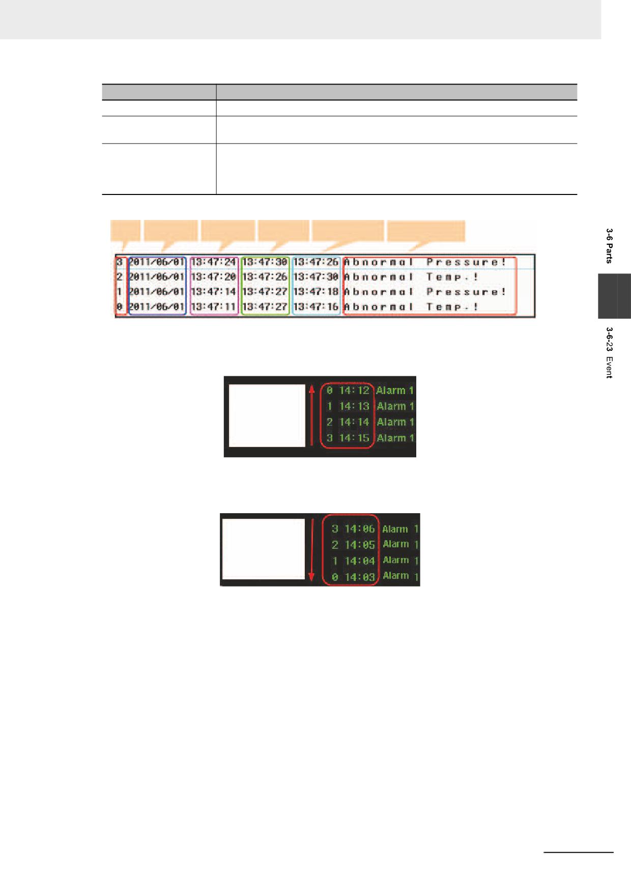
Time ascending Order Display: When this option is checked, the latest occurred event will be
displayed on the bottom and the event sequence No. and the
time will ascend from top to bottom, as shown below.
Ascending order
by time, new
trigger events
are displayed on
the following.
When this option is not checked, the event will be displayed in the descending order, i.e. the
latest occurred event will be displayed on the top, and event sequence No. and the time will
descend from top to bottom, as shown below.
Descending order
by time, new
trigger events are
displayed on the
top.
3
Press the [OK] button to complete the setup, and adjust the position and the size of the Event
component.
NB-series Programmable Terminals NB-Designer Operation Manual(V106)
3-173
3 Functions of NB-Designer
Example of Event
1
First create a new project and [Save] it.
2
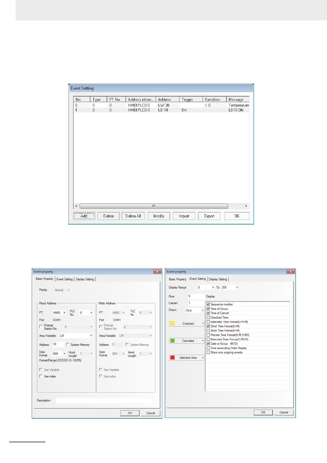
Add two events in the [Event Setting], as shown below.
Where, the 1st event is the pop-up screen 4 and the 2nd event is the pop-up screen 5.
3
Add one Indirect Screen in screen 0 of the newly created project and its [Read address] of LW5.
4
Add one Event component in screen 0, as shown below.
Place one Vector Graphics under the Event component to enhance the display effect.
3-174
NB-series Programmable Terminals NB-Designer Operation Manual(V106)
3 Functions of NB-Designer
5
Add one Bit Switch to control the ON/OFF state of LB10.
6
Add one Text component with the content of “Increase water temperature”.
7
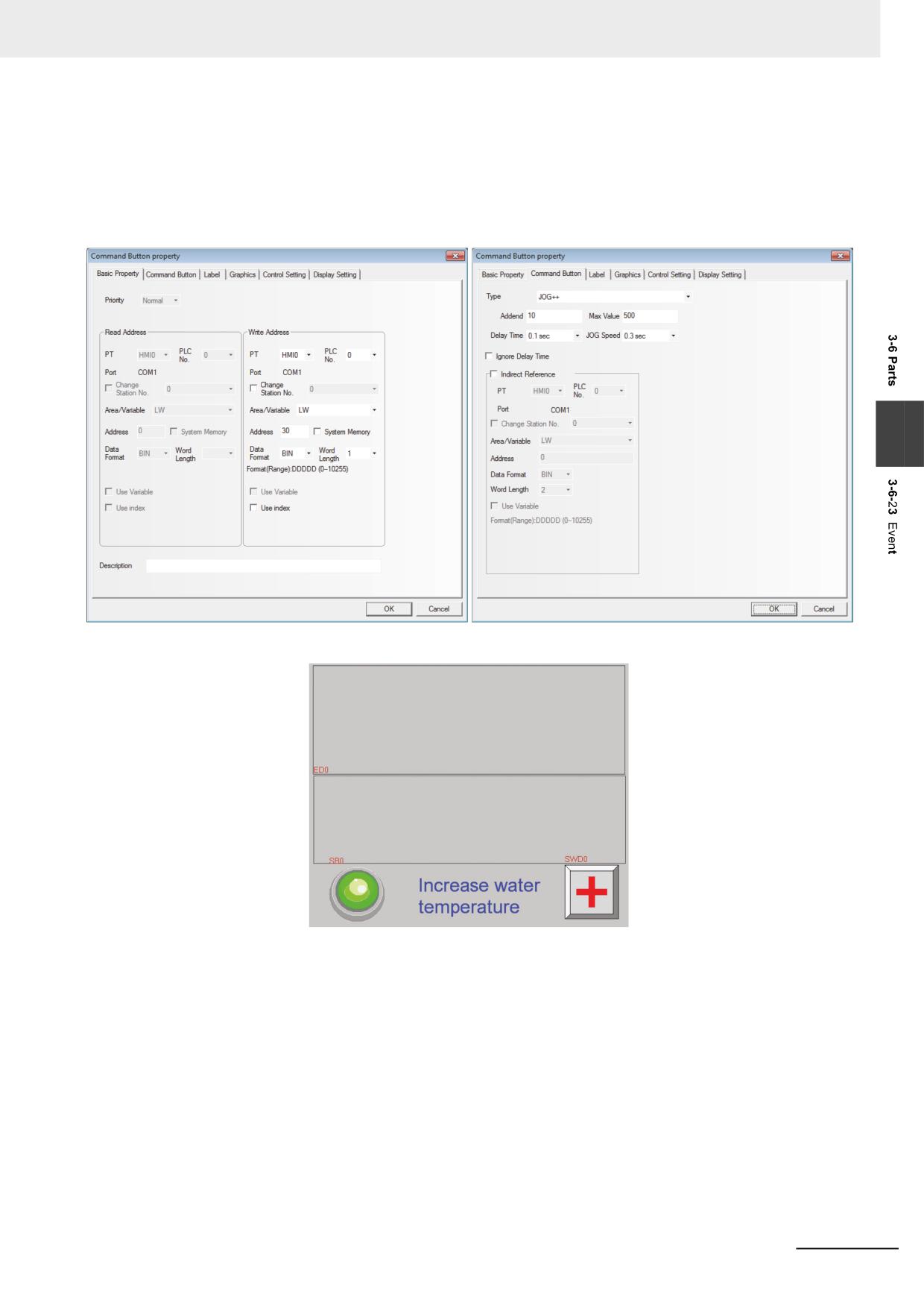
Add one Command Button component with the settings as shown below:
3
Finally, the screen 0 is shown as below:
NB-series Programmable Terminals NB-Designer Operation Manual(V106)
3-175
3 Functions of NB-Designer
8
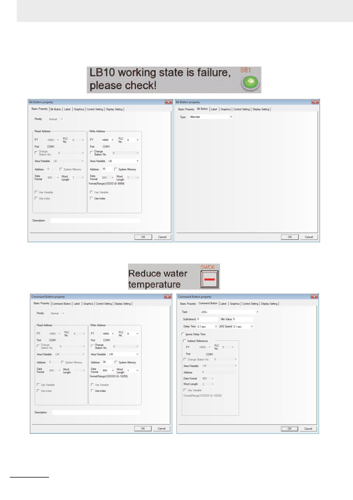
Create screen 4 with one Text component and one Bit Switch component controlling the LB10,
as shown below.
9
Create screen 5 with one Text component and one Command Button component, as shown below.
3-176
NB-series Programmable Terminals NB-Designer Operation Manual(V106)
3 Functions of NB-Designer
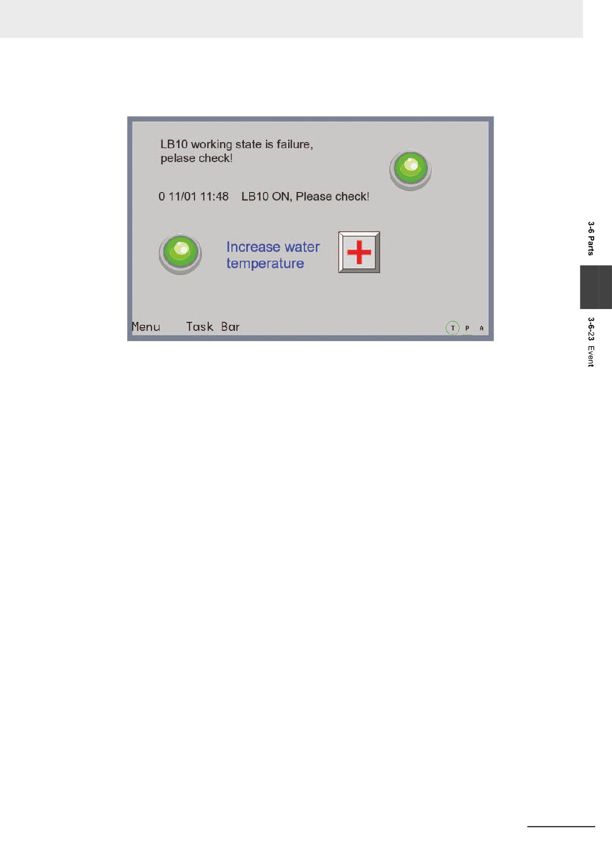
10 After [Save], [Compile], [Online/Offline test] or [Download] is selected, the operation effect of
the program is as shown below.
3
When LB10 or LW30 is triggered for its corresponding triggering conditions is satisfied, the
related event information will be displayed. The popup screen 4 and screen 5 for the 2 events
registered in the [Event Setting] are the pop-up screens to be ejected when the event is
triggered.
Note 1
For the pop-up screen, it will pop up only when the event is confirmed.
2
For the pop-up screen for the event triggering, it can be closed by the <Close screen> for the Function Key
or the triggering function <Write Data: No>.
NB-series Programmable Terminals NB-Designer Operation Manual(V106)
3-177
3 Functions of NB-Designer
3-6-24
Note Book
Note Book component can modify or display the data in the specified word memory.
The value of the communications address is dealt as ASCII character. The input data is saved to a
consecutive memory with the “Read Address” as the first address. Low-byte character codes are
displayed on the left, while high-byte character codes are displayed on the right. It supports the display
of the multi-line text content and page turning, and can be used to make the operations such as Copy,
Cut and Paste etc. for the text contents in the selected area.
Process of adding one Note Book component
1
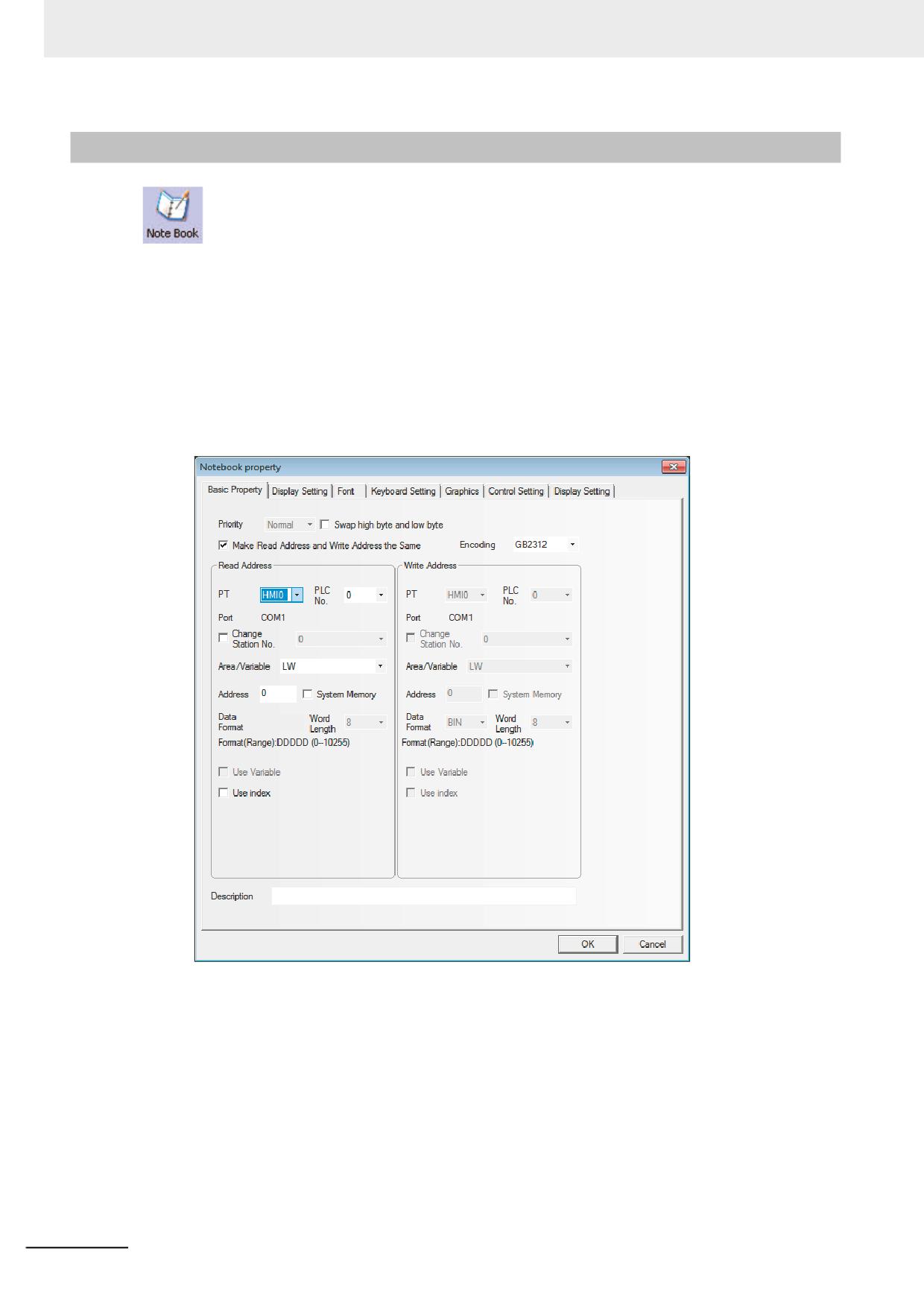
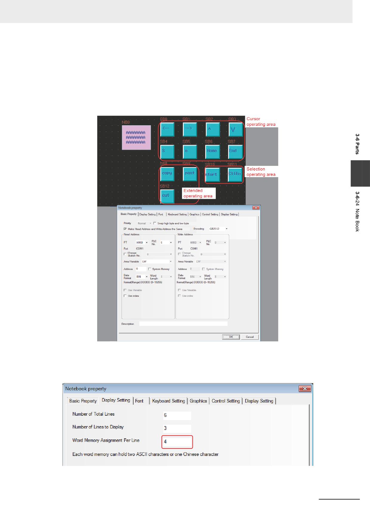
Press the Note Book component icon, drag it to the screen, then the [Basic Properties] dialog
box of the Note Book component will pop up.
3-178
NB-series Programmable Terminals NB-Designer Operation Manual(V106)
3 Functions of NB-Designer
2
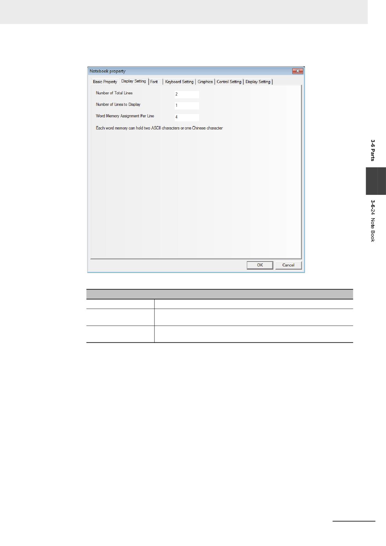
Switch to the [Display Setting] tab.
3
Descriptions of Note Book
Number of Total Lines
Refers to the total lines of the text that can be input.
Number of Display
Refers to the lines in the display area.
Lines
Word Memory
Refers to the maximum data length displayed in each line with the unit of
Assignment Per Line
“word”. It is one byte for ASCII character and two bytes for one word.
NB-series Programmable Terminals NB-Designer Operation Manual(V106)
3-179
3 Functions of NB-Designer
3
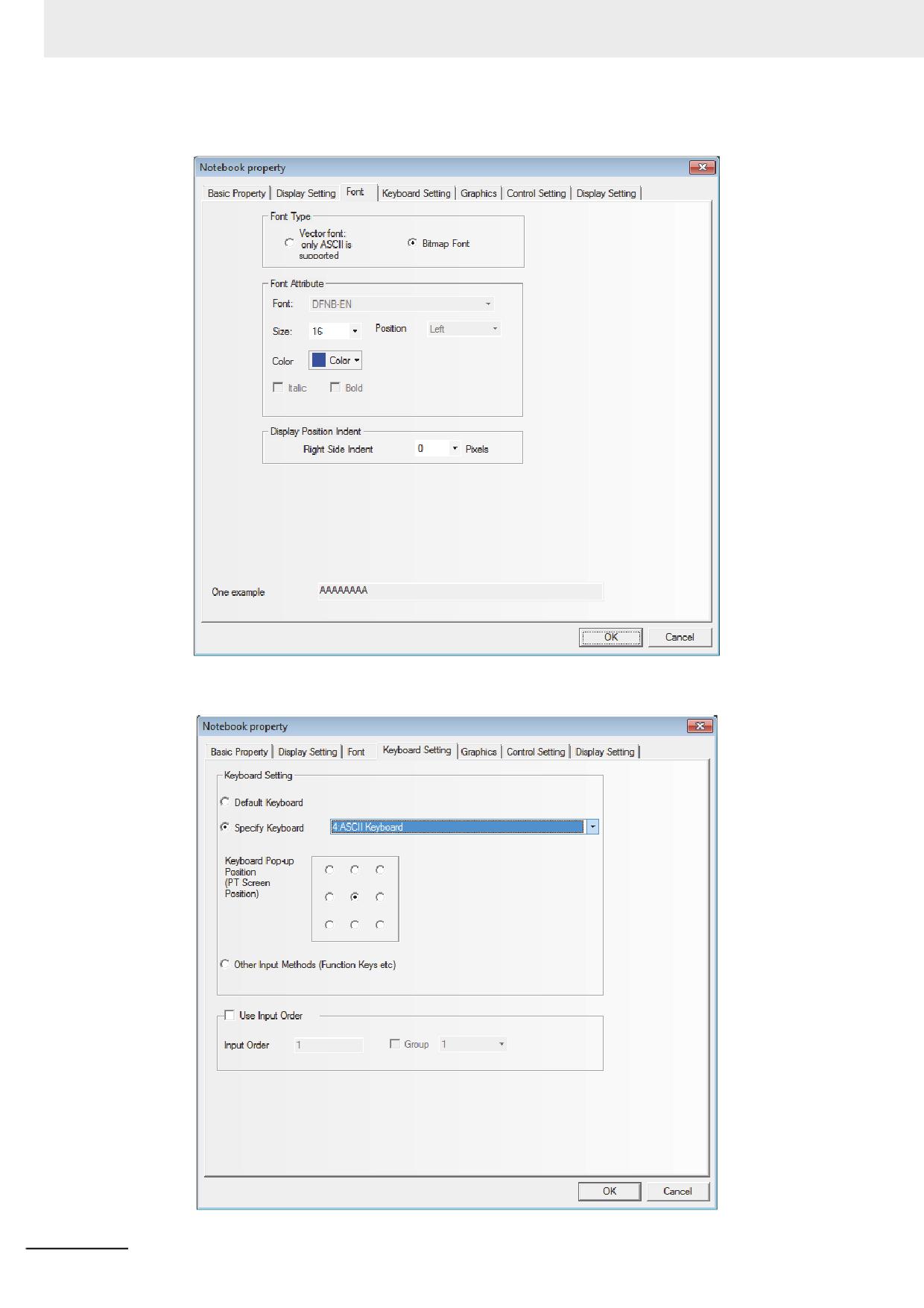
Switch to the [Font] tab.
4
Switch to the [Keyboard Setting] tab.
3-180
NB-series Programmable Terminals NB-Designer Operation Manual(V106)
3 Functions of NB-Designer
5
Switch to the [Graphics] tab and select the Vector Graphics or bitmap representing the
touching area and touching state.
6
Switch to the [Control Setting] tab and make the Security Setting and set the Triggering action.
7
Press the [OK] button to complete the setup of the Note Book component.
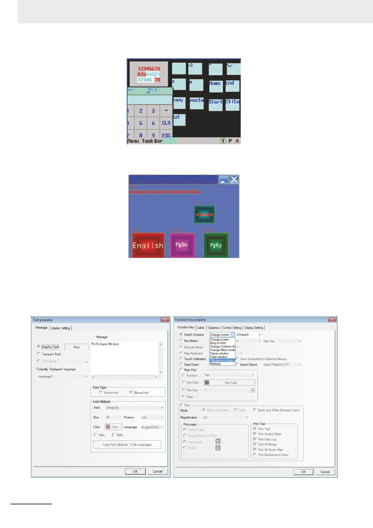
The editing of Note Book is as shown below:
3
The specific Properties of the Note Book are set as shown below:
LW 9170 is used to realize page turning of the Note Book, and its value represents the start line
of the input area. The user can change this value to realize the display of the Note Book in the
page-turning way.
NB-series Programmable Terminals NB-Designer Operation Manual(V106)
3-181
3 Functions of NB-Designer
The offline test effect of the Note Book is as shown below:
Example of using Text Input component to realize PinYin Input
The edited effect is as shown below:
PinYin Input Window
Please input your name:
The specific operation is as follows:
1
Make “PinYin Input Window” as the screen title, and place one Text component, as shown
below.
2
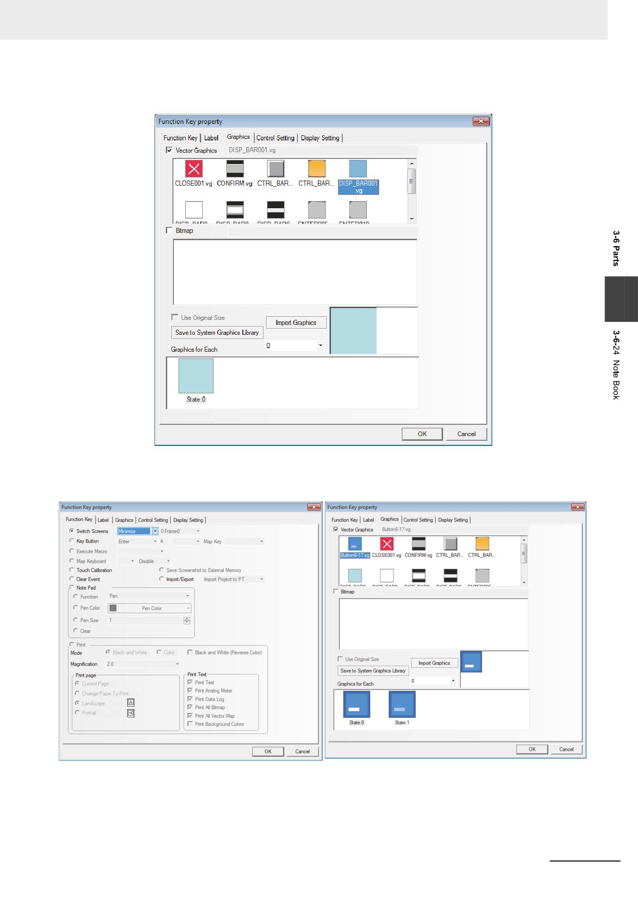
Place another function key with the Property “Switch Screen” of “pop-up screen title bar”, which
overlaps above the Text component (i.e. PinYin Input Window).
3-182
NB-series Programmable Terminals NB-Designer Operation Manual(V106)
3 Functions of NB-Designer
Check “Vector Graphics” in the “Graphics” tab and select one Vector Graphics, as shown
below.
3
3
Place one function key with the Property of “Switch Screen” of “Minimize” in the “Function Key”
tab. Check “Vector Graphics” in the “Graphics” tab and select one Vector, as shown below.
NB-series Programmable Terminals NB-Designer Operation Manual(V106)
3-183
3 Functions of NB-Designer
4
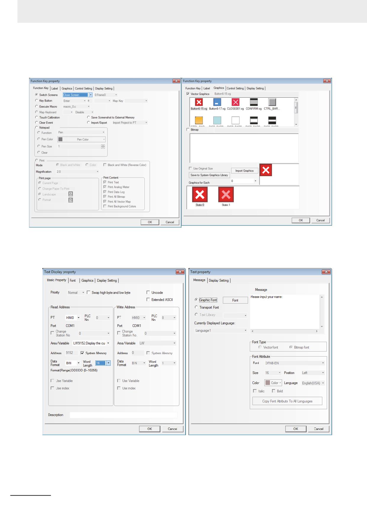
Place one function key with the Property of “Switch Screen” of “Close Screen” in the “Function
Key” tab. Check “Vector Graphics” in the “Graphics” tab and select one Vector, as shown
below.
5
Place one Text Display component LW9152 with the “Word Length” of “16”.
6
Place one static Text Display component with the contents of “Please input your name:”.
3-184
NB-series Programmable Terminals NB-Designer Operation Manual(V106)
3 Functions of NB-Designer
7
Place another Text Input component LW20 with the “Word Length” of “4”.
8
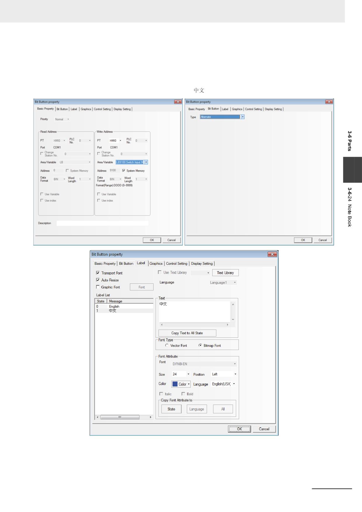
Create one Bit Button component with the “Write Address” of LB9100 in the “Basic Properties”
tab, “Type” in the “Bit Button” tab of “Alternate”, “Transport Font” being checked together with
the State 0 and State 1 of “English” and “
” respectively.
3
NB-series Programmable Terminals NB-Designer Operation Manual(V106)
3-185
3 Functions of NB-Designer
9
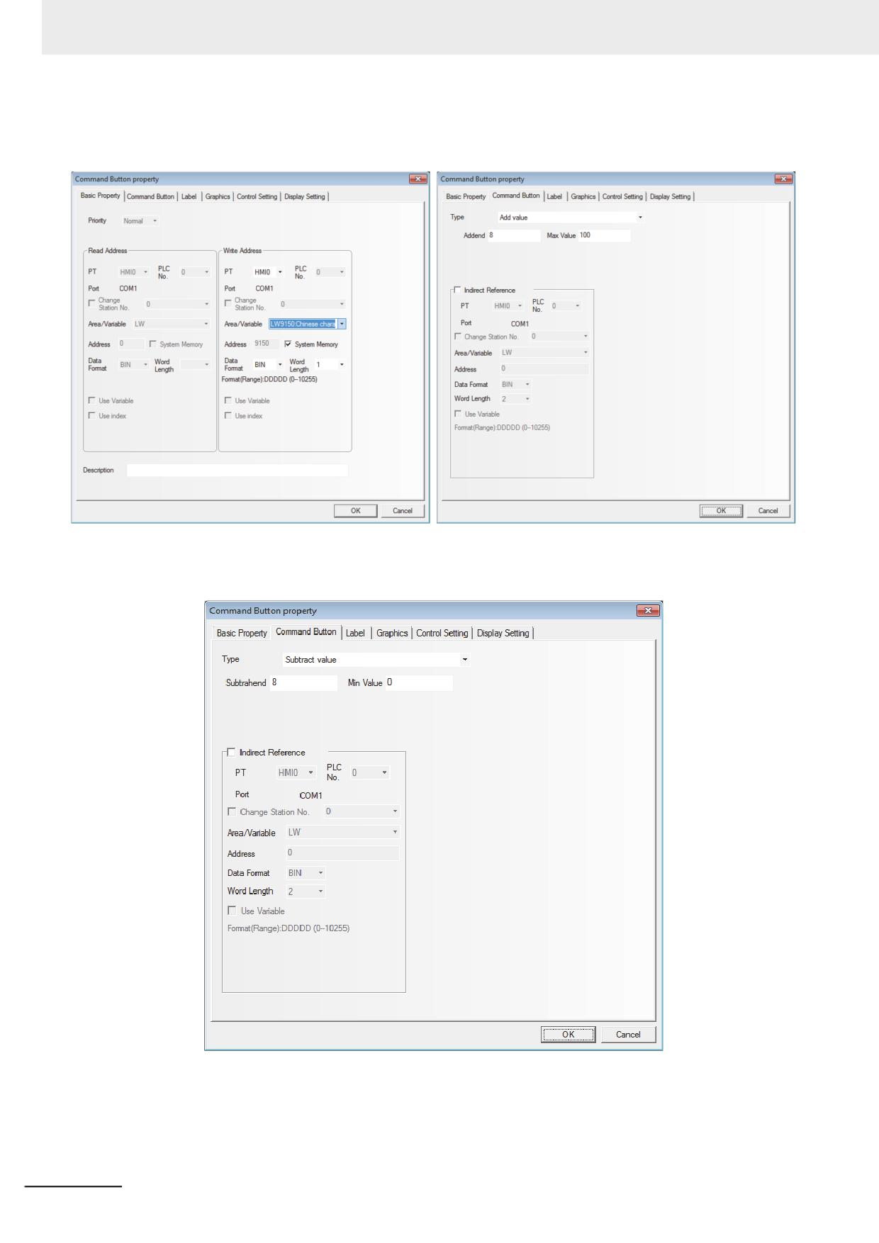
Place one Command Button component LW9150 with “Type”, “Addend” and “Max Value” of
“Add value”, “8” and “100” respectively in Command Button tab and the Label of “PgDn”.
10 Place one Command Button component LW9150 with “Type”, “Subtrahend” and “Min Value” of
“Subtract value”, “8” and “0” respectively in Command Button tab and the Label of “PgUp”.
3-186
NB-series Programmable Terminals NB-Designer Operation Manual(V106)
3 Functions of NB-Designer
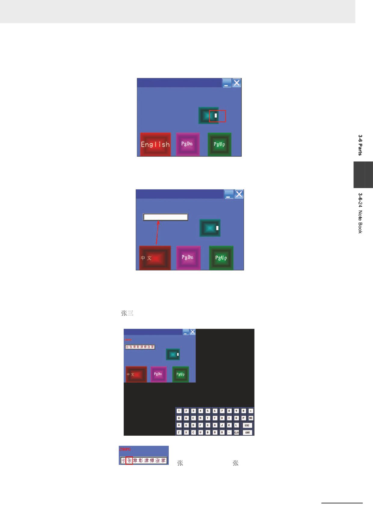
After all the components are placed well, the operation are as follows:
1
Trigger the Text Input component to make the cursor appear, as shown below.
PinYin Input Window
Please input your name:
2
Click the English-Chinese Switch once, then the input bar for Chinese input will appear, as
3
shown below.
PinYin Input Window
Please input your name:
3
Several homophones will appear in the Chinese input bar after the PinYin character is input,
and you can use the “PgUp” or “PgDn” button to realize page turning, and trigger the related
Chinese character to complete one Chinese character input process. As shown below, for
example, if “
” needs to be input, you just need to enter “zhang” through the character
keyboard.
PinYin Input Window
Please input your name:
Later, when
“
” is triggered, “
” will be displayed in the Text Input
component, as shown below.
NB-series Programmable Terminals NB-Designer Operation Manual(V106)
3-187
3 Functions of NB-Designer
PinYin Input Window
Please input your name:
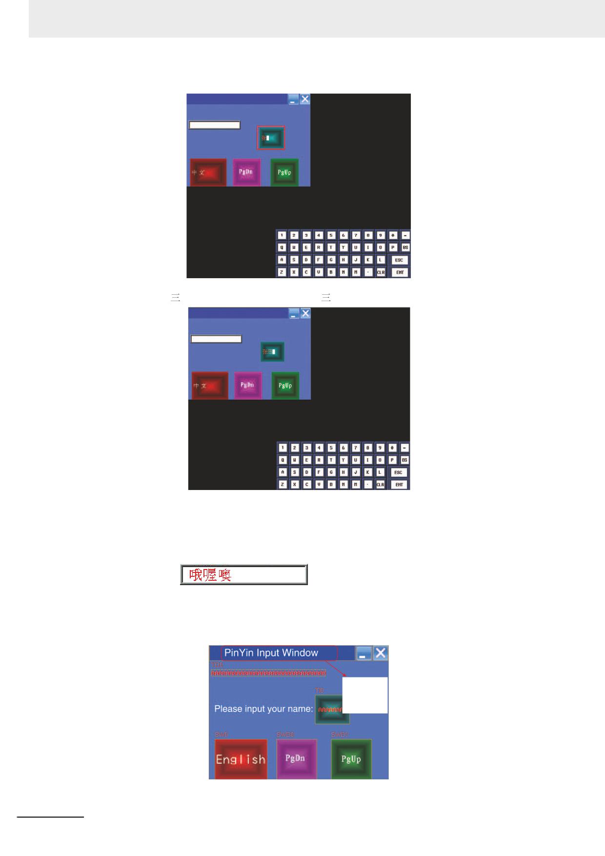
Trigger “
” after PinYin “san” is input, “
” will be displayed in the Text Input component.
PinYin Input Window
Please input your name:
Press “ENT” button in character keyboard to complete this input.
Addition1 If the character needs to be changed during the input process, the function keys of “BACK” or
“Clear” in the keyboard can be used to realize this operation.
2
, triggering the blank area of the Chinese Character Display
screen can realize the movement of this screen, which is similar to the screen console of the
function key.
4
Clicking the “PinYin Input Window” bar can realize the screen movement, as shown below.
Press the
blue title bar
can be move
the screen
3-188
NB-series Programmable Terminals NB-Designer Operation Manual(V106)
3 Functions of NB-Designer
5
Clicking the “Minimize (i.e. “-”) icon” can make the screen minimized to the task bar. And
clicking the task bar again will make the screen return to the state before it is minimized.
6
Clicking the “Close (i.e. “X”)” icon to close the screen.
The PinYin Input for the Note Book is similar to that for the Text component, and many
Properties of the Note Book component are realized through the function keys.
3-6-25
Word Neon Lamp
The text string which is specified as Label is displayed in loopy-moving way, and it supports
the label contents corresponding to 256 (max.) states in the loopy-moving way.
3
Process of adding one Word Neon Lamp component
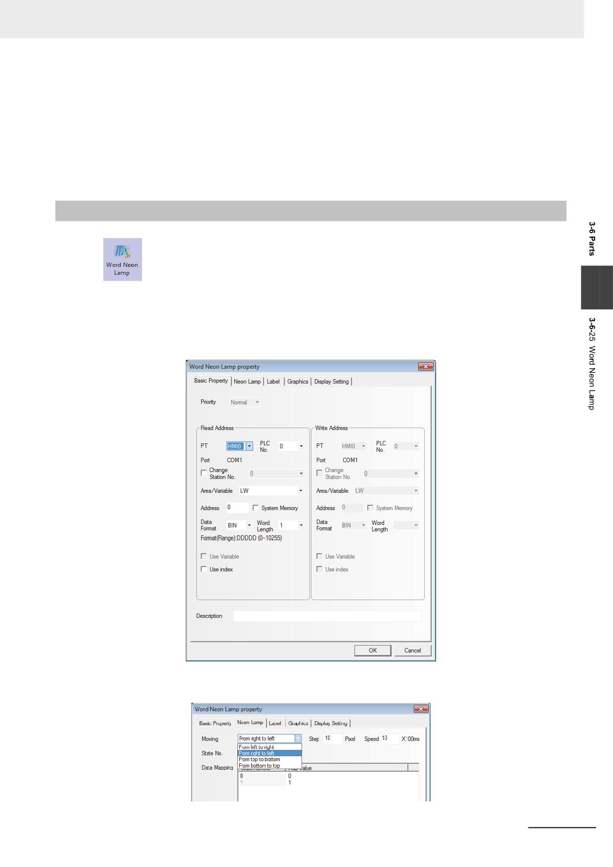
1
Press the Word Neon Lamp component icon, drag it to the screen, then the [Basic Properties]
of Word Neon Lamp component will pop up.
2
Switch to the [Neon Lamp] tab and make settings of “Moving Type”, “State No.”, “Step” and
“Speed” respectively.
NB-series Programmable Terminals NB-Designer Operation Manual(V106)
3-189
3 Functions of NB-Designer
3
Switch to the [Label] tab and add the text corresponding to the state.
4
Switch to the [Graphics] tab and select the Vector Graphics or bitmap representing the
touching area and touching state.
5
Press the [OK] button to complete the setup of the Word Neon Lamp component.
3-6-26
Bit Neon Lamp
The text string which is specified as Label displayed in loopy-moving way, and it supports the
label contents corresponding to State 0 and State 1 in the loopy-moving way.
The difference of the Word Neon Lamp and the Bit Neon Lamp is the controlling method, and the
former selects the different states ranging from 1 to 256 by changing the memory value, while the latter
changes the display state (only 2 states available) by changing the state of the control bit.
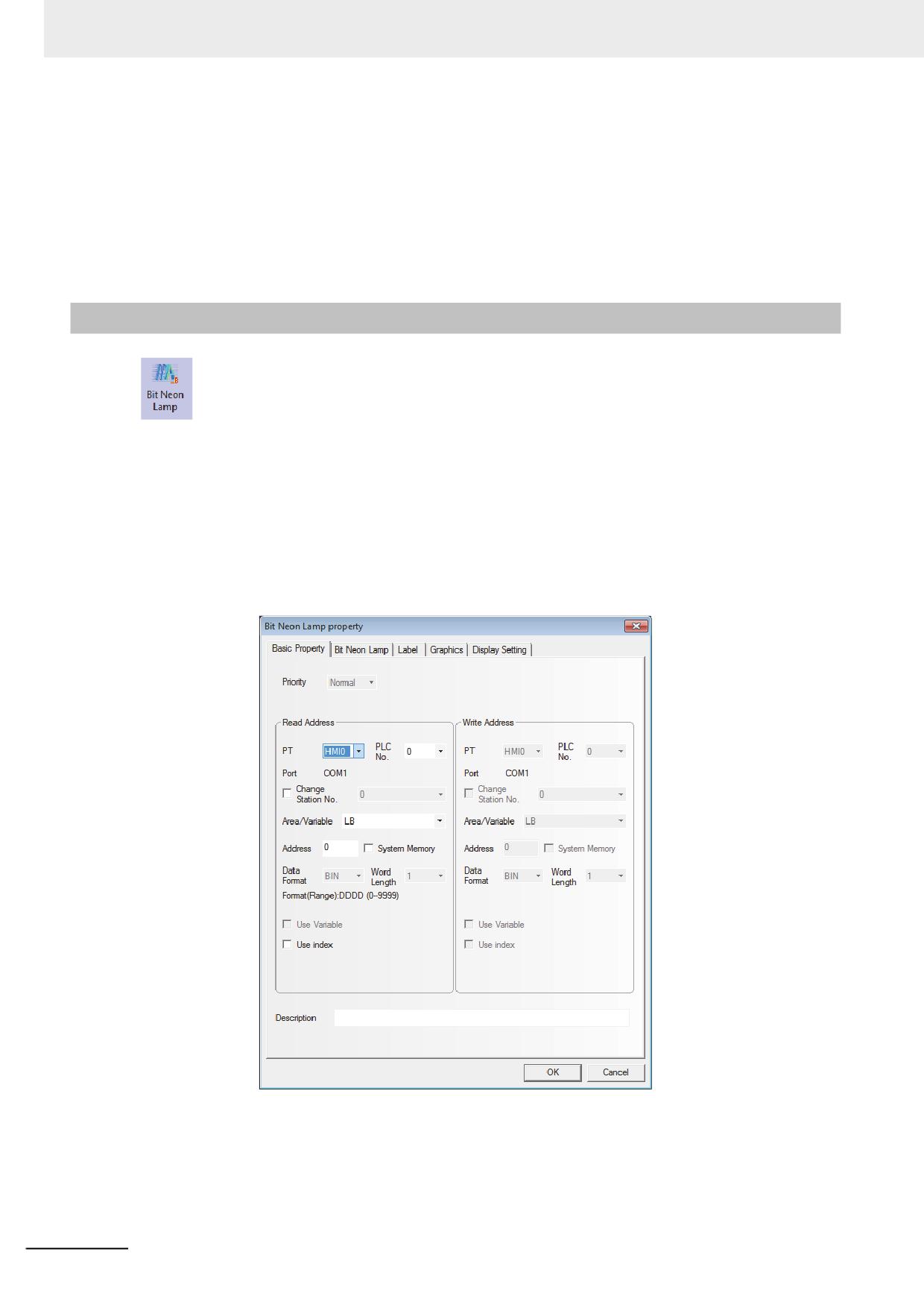
Process of adding one Bit Neon Lamp component
1
Press the Bit Neon Lamp component icon, drag it to the screen, then the [Basic Properties] of
Bit Neon Lamp component will pop up.
3-190
NB-series Programmable Terminals NB-Designer Operation Manual(V106)
3 Functions of NB-Designer
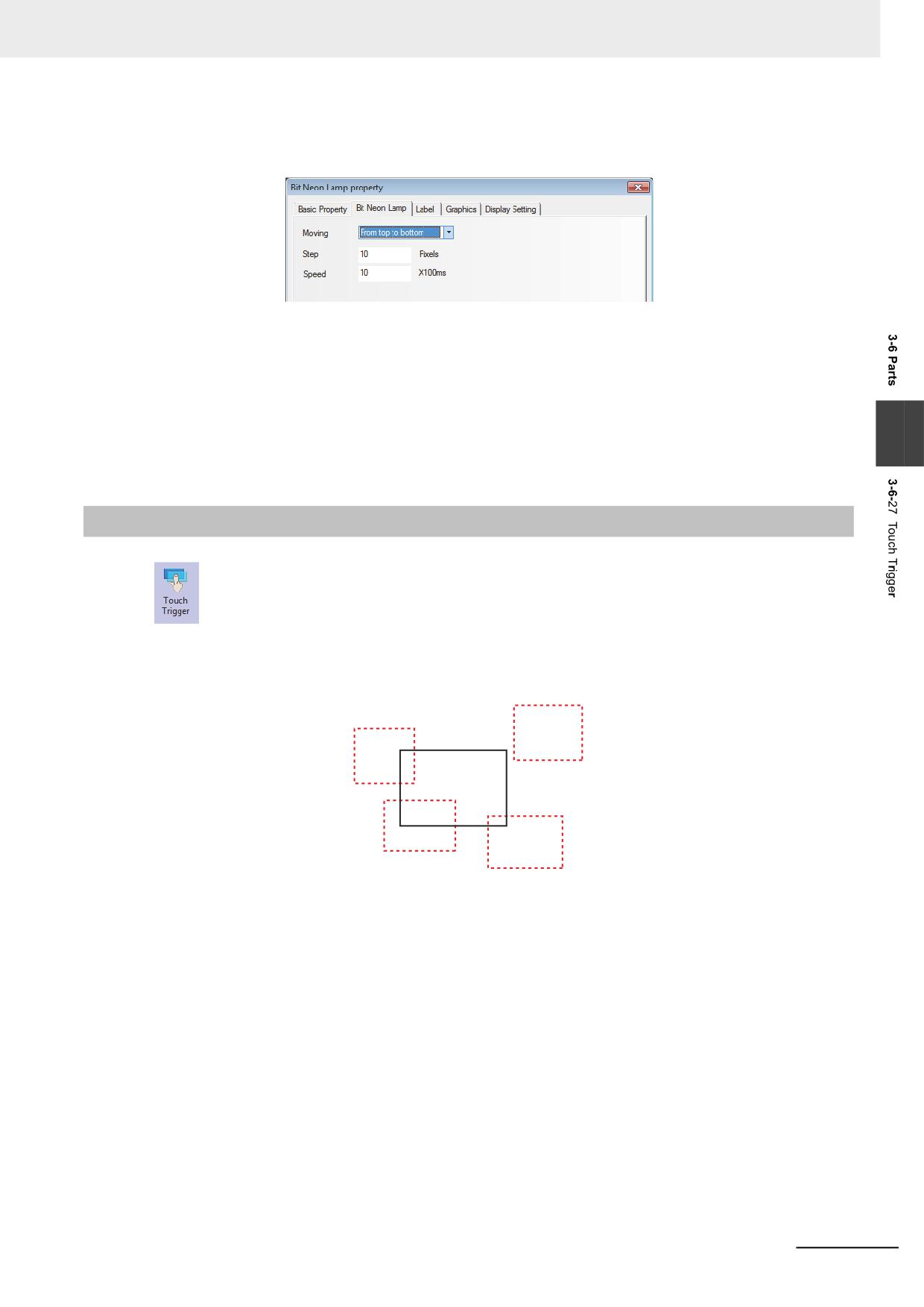
2
Switch to the [Bit Neon Lamp] tab and make settings of “Moving Type”, “Step” and “Speed”
respectively.
3
Switch to the [Label] tab and add the text corresponding to the state.
4
Switch to the [Graphics] tab and select the Vector Graphics or bitmap representing the
touching area and touching state.
3
5
Press the [OK] button to complete the setup of the Bit Neon Lamp component.
3-6-27
Touch Trigger
The Touch Trigger component is applicable to the conditions where the several components
can be triggered to act not through the triggering method. When the triggering conditions for the
specified memory of the Touch Trigger component are satisfied, the components placed in the valid
area for the Touch Trigger component can be triggered to act.
2)
3)
Touch Trigger
component
4)
1)
1), 3) and 4) locate in the valid triggering area, while 2) locates in the invalid triggering area.
Therefore, when the set triggering conditions for the specified memory of the Touch Trigger component
are satisfied, the components in area 1), 3) and 4) will be triggered, while that in area 2) will not be
triggered.
NB-series Programmable Terminals NB-Designer Operation Manual(V106)
3-191
3 Functions of NB-Designer
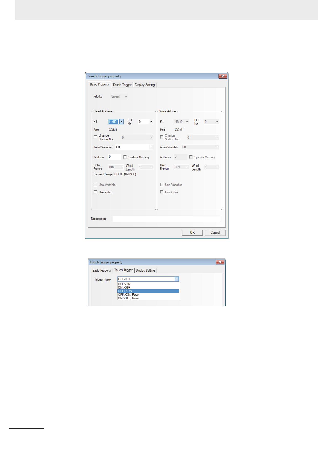
Process of adding one Touch Trigger component
1
Press the Touch Trigger component icon, drag it to the screen, then the [Basic Properties]
dialog box of Touch Trigger component will pop up.
2
Switch to the [Touch Trigger] tab and select the Trigger Type.
3
Press the [OK] button to complete the setup of the Touch Trigger component.
3-192
NB-series Programmable Terminals NB-Designer Operation Manual(V106)
3 Functions of NB-Designer
3-6-28
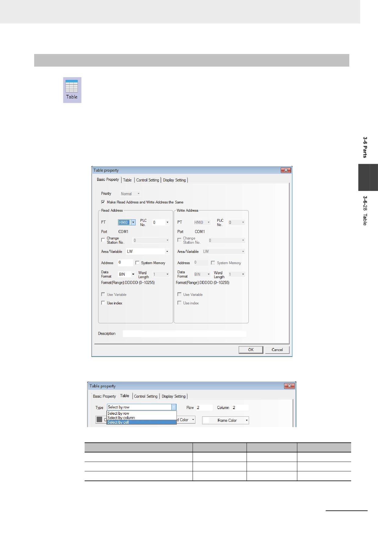
Table
The Table component can make the selection type of “Select by row”, “Select by Column” and
“Select by cell”. The user can set the “Row”, “Column”, “Color when Selected”, “Background Color”,
“Border Color”, and write the selected Row No. and Column No. into the specified memory.
Process of adding one Table component
1
Press the Table component icon, drag it to the screen, then the [Basic Properties] dialog box of
the Table component will pop up.
3
2
Switch to the [Table] tab and make the settings of “Row”, “Column” and “Type”.
The related Properties are as follows:
Type
Select by row
Select by col
Select by cell
memory corresponding to Row
First address
-
First address
memory corresponding to Column
-
First address
First address + 1
Number of Occupied memories
1
1
2
NB-series Programmable Terminals NB-Designer Operation Manual(V106)
3-193
3 Functions of NB-Designer
3
Switch to the [Control Setting] tab and make the Security Setting and set the Triggering action.
4
Press the [OK] button to complete the setup of the Table component.
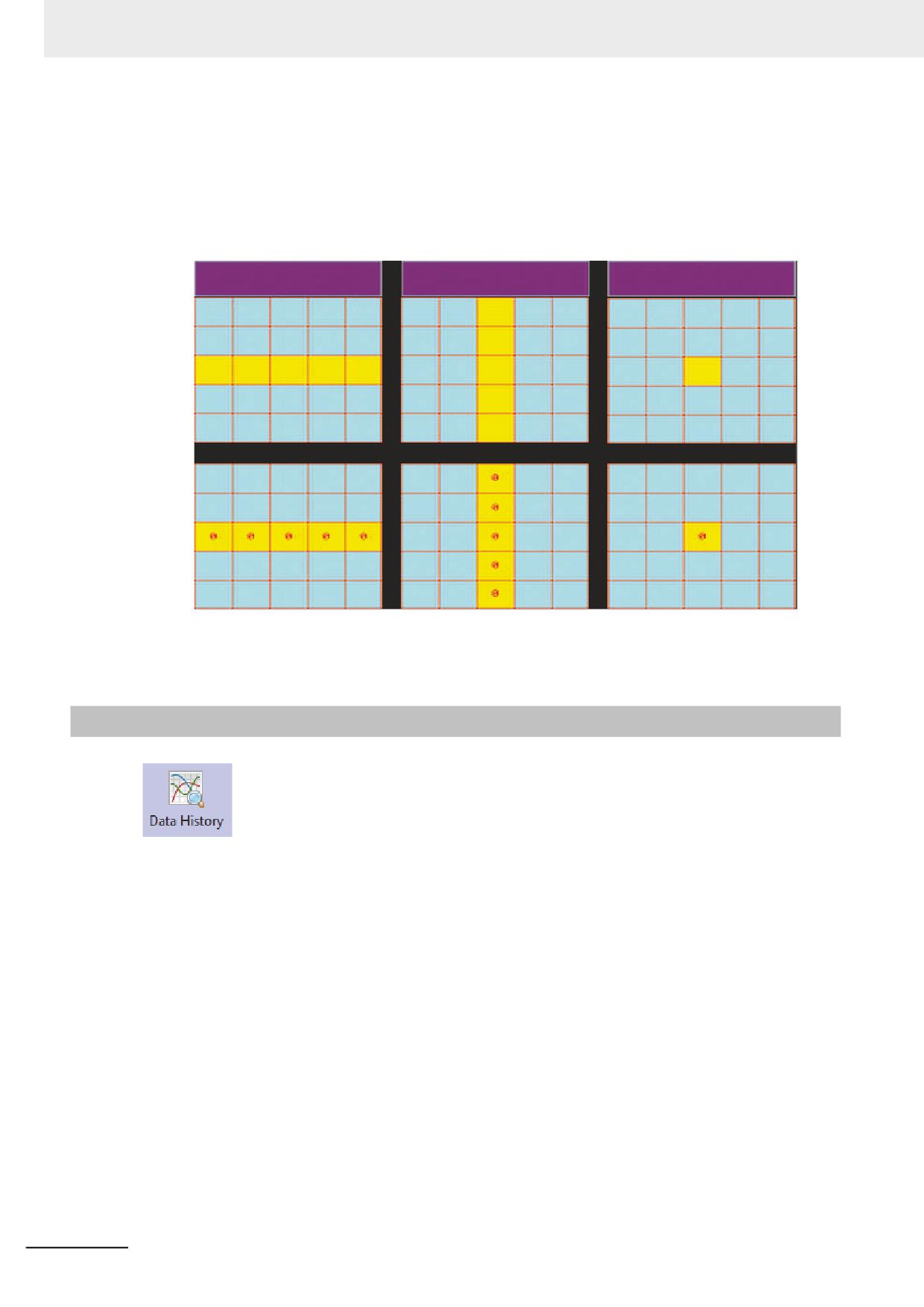
The test effect of the Table component is as shown below.
Select by row 2
Select by col 2
Select by cell 2
Grid component application
If required, the Table component can also be used in combination with the Number Input component
and the Macro, thus controlling the display condition through the Macro.
3-6-29
Data History
The Data History component can be used to read a series of date in consecutive memories
from the specified word memory(s) inside PT, PLC or word memory(s) of the controller periodically and
display them in the table form.
Note 1
The sampled data must be consecutive. When the “Save to Recipe Data Field” is checked in the [Save
Data History] tab, only the saving of a little amount of data is possible for the limited capacity of recipe data
field.
2
The [Read Address] for the Data History component is the memory address for data sampling by the 1st
channel.
3
The Word Length of memory for Data History component is determined by the channel number, i.e. if
channel number is m (0<m<17), the World Length will be m.
4
Using the Data History component, the user must be check one or both of “Save to Recipe Data Field” and
“Save to External Device” options in the [Save Data History] tab in the [Data History Component Property]
dialog box.
3-194
NB-series Programmable Terminals NB-Designer Operation Manual(V106)
3 Functions of NB-Designer
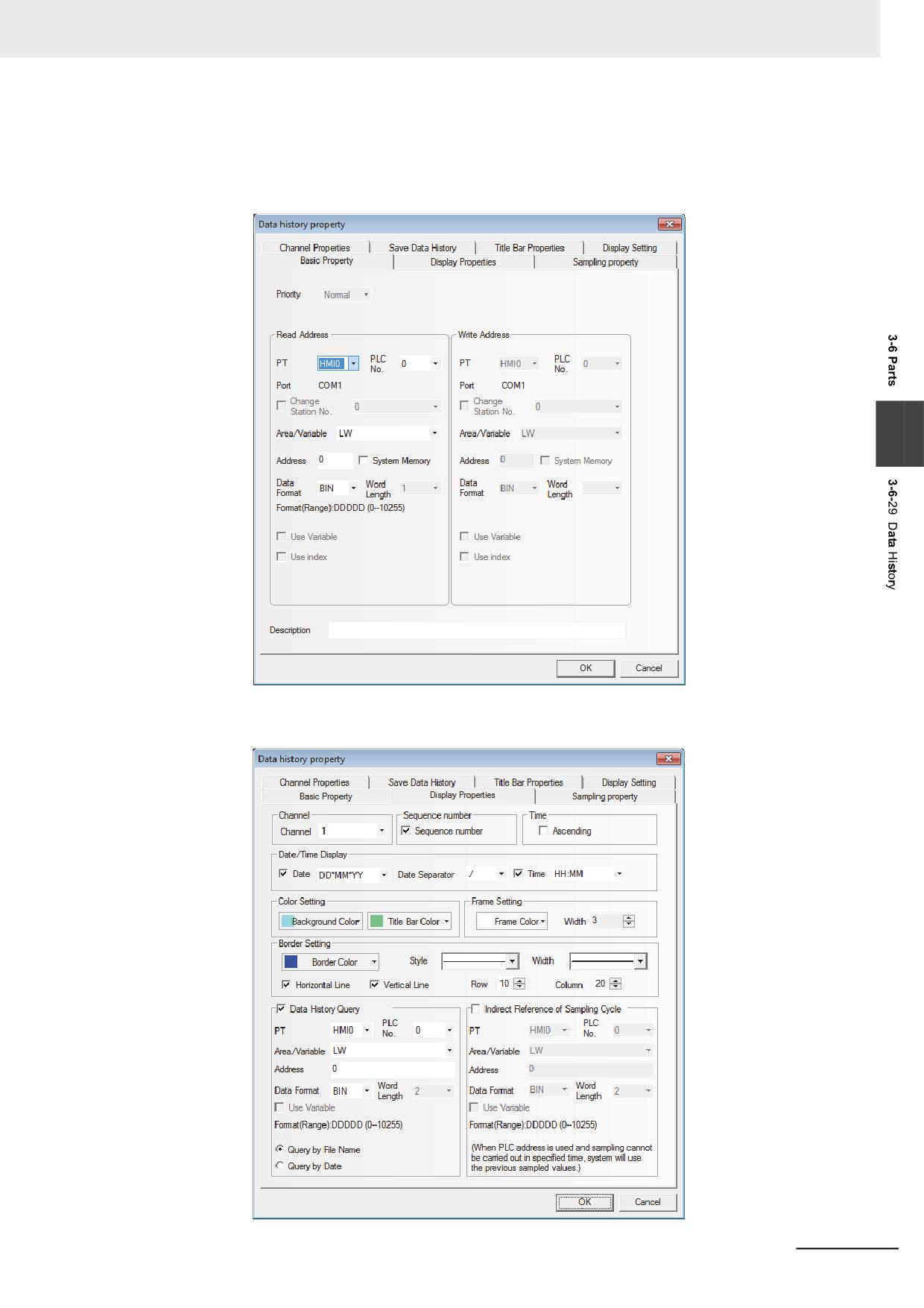
Process of adding one Data History component
1
Press the Data History component icon, drag it to the screen, then the [Basic Properties] dialog
box of the Data History component will pop up.
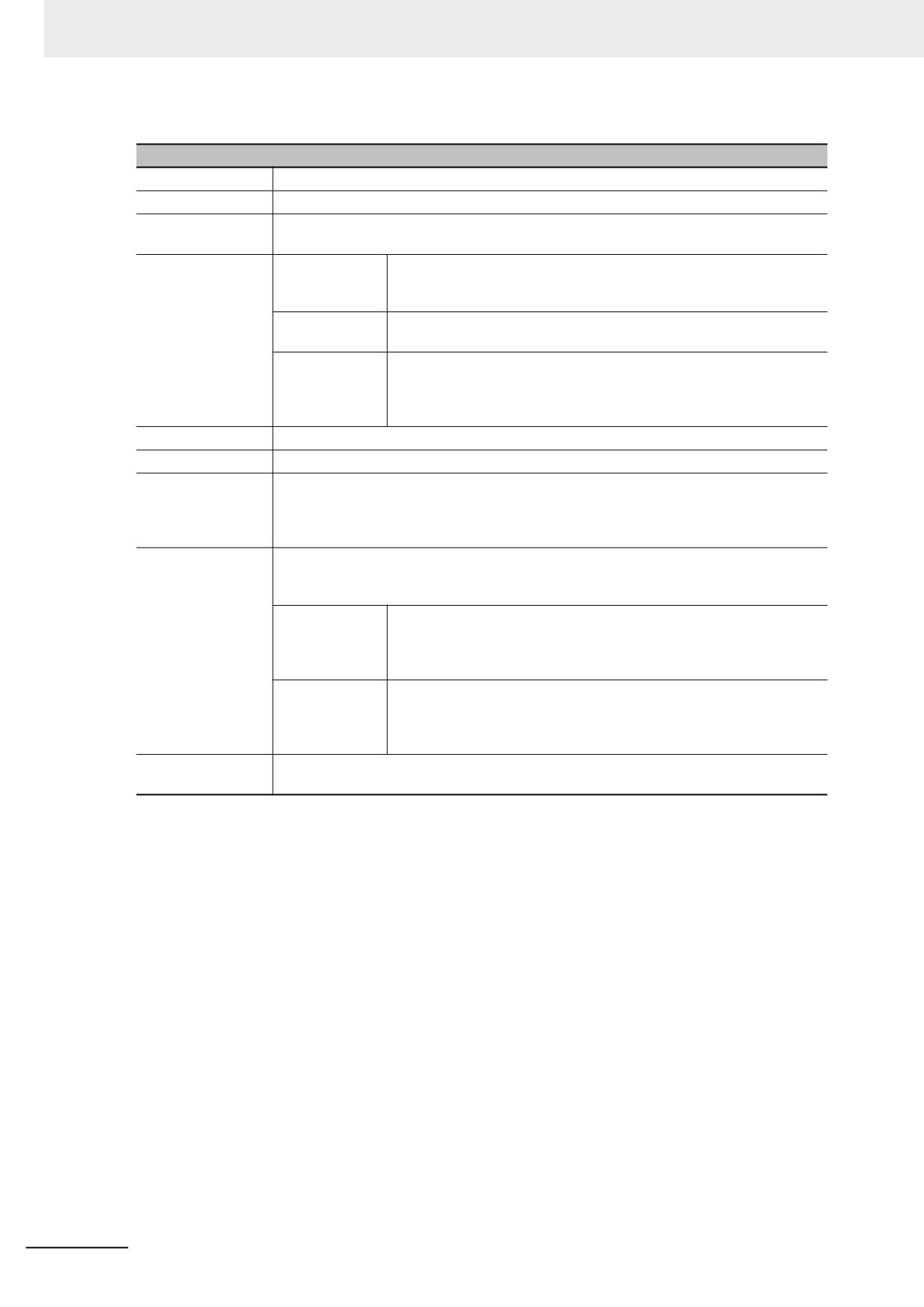
3
2
Switch to the [Display Properties] tab and make the settings of display format and color etc.
NB-series Programmable Terminals NB-Designer Operation Manual(V106)
3-195
3 Functions of NB-Designer
Descriptions of Display Properties
Channel
Refers to the channel number of the memory to be sampled, and the channel is up to 16.
Sequence number
Determines whether to display the No. of the sampling data information.
Ascending
When this option is checked, the sampling data information will be displayed in the
ascending order, i.e. the latest sampling data will be displayed on the bottom.
Date/Time Display
Date
Checking in the checkbox allows the sampling date displayed in the
selected date format. The 3 formats are available, and YY, MM and
DD refer to the year, month and date respectively.
Date Separator
Selects the data separator with 3 formats available. For example:
11/06/24.
Time
Checking it means the sampling time will be displayed and the time
format can be selected. There are 3 formats available, and HH, MM,
SS and MS refer to the hour, minute, second and millisecond
respectively.
Color Setting
Sets the Background Color and Title Bar Color for the table respectively.
Frame Setting
Sets the Frame Color and Width for the table.
Border Setting
Set the color, types, and width of Border, row spacing, and column spacing with the unit
of “pixel point”. Checking the “Horizontal Line” check box means the border will be
displayed horizontally, and checking “Vertical Line” means the border will be displayed
vertically.
Data History Query
The historical sampled data stored in the external memory can be searched by address
of the word memory specified in “Data History Query” setting. The Word Length of the
specified memory address is 2 by default.
Query by File
With the “Query by File Name” being checked, it means to call out the
Name
data history sampled today or in the latest day when the value of
specified memory is 0, while the data history sampled in the last time
when the value of specified memory is 1, and so on.
Query by Date
When “Query by Date” is checked, the date will be input into the
specified memory and the data history corresponding to the date will
be called out. The date format is yyyymmdd, where yyyy, mm and dd
refer to year, month and date respectively.
Indirect Reference
When Indirect Reference is used, the sampling time will be read from the specified
of Sampling Cycle
memory.
Note When the variable is specified in the sampling cycle, if the value cannot be obtained within the regulated
time, the value which was obtained previously will be used.
3-196
NB-series Programmable Terminals NB-Designer Operation Manual(V106)
3 Functions of NB-Designer
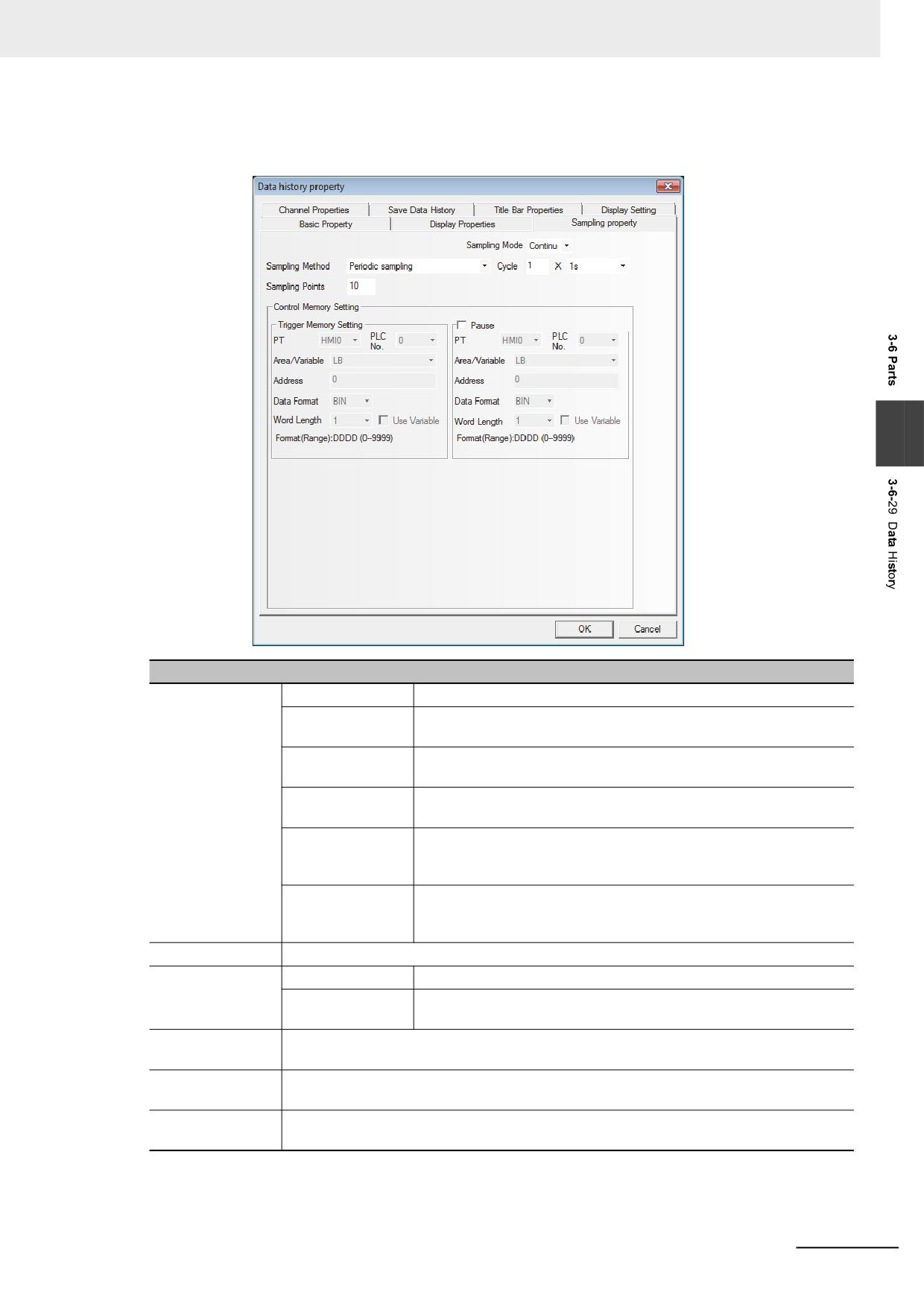
3
Switch to the [Sampling Property] tab and make the settings of “Sampling Method”, “Cycle”,
“Sampling Points” and “Pause-Clear” and etc.
3
Descriptions of Background Property
Sampling Method
Periodic sampling
The data is sampled timely.
OFFON trigger
Only when the state of the specified bit address turns ON from OFF,
sampling
the sampling is triggered.
ONOFF trigger
Only when the state of the specified bit address turns OFF from ON,
sampling
the sampling is triggered.
OFFON trigger
Only when the state of the specified bit address changes, the
sampling
sampling is triggered.
OFFON reset
Only the state of the specified bit address turns ON from OFF, the
trigger sampling
sampling is triggered, and the state of the specified bit address will be
reset automatically after the triggering.
ONOFF reset
Only the state of the specified bit address turns OFF from ON, the
trigger sampling
sampling is triggered, and the state of the specified bit address will be
reset automatically after the triggering.
Cycle
Refers to the interval between 2 sampling points with the unit of “s”or “100 ms”.
Sampling Mode
Continue
When all the sampling points end, the sampling still continues.
Once
When all the sampling points end, the sampling will stop, which
means sampling is only performed once.
Sampling Points
When the sampling method is “Once”, the sampling will stop after the set “Sampling Points”
is finished.
Trigger memory
When the Trigger memory Setting is used for the sampling method, the memory address to
Setting
be read will be specified.
Pause- Clear
The default Word Length is 2. “Pause” function can stop the data sampling operation
temporarily. In addition, the “Clear” function here is invalid for the Data History component.
Note When the trigger sampling is used, if multiple samplings are executed at the same timing, only single value
might be acquired.
When such a state is assumed, place the Data Transmission component and others on the Common Sheet
and acquire the necessary data at local memory to perform the sampling for the local memory.
NB-series Programmable Terminals NB-Designer Operation Manual(V106)
3-197
3 Functions of NB-Designer
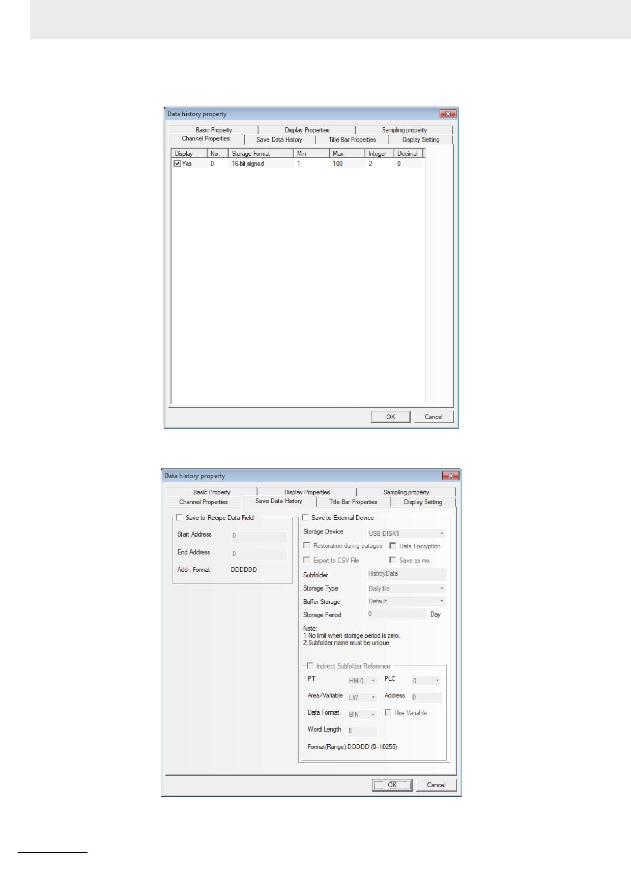
4
Switch to the [Channel Properties] tab and set the display information for each channel.
5
Switch to the [Save Data History] tab and set the “Start Address.” etc. to be saved.
3-198
NB-series Programmable Terminals NB-Designer Operation Manual(V106)
3 Functions of NB-Designer
•
When the Data History component and the Data Log component are used in combination and
their addresses are the same, it just needs to set “Save to Recipe Data Field” for either of
them.
•
If the Data History component is needed to display the value of the Data Log, the value in PLC
can be transmitted to the LW of the local memory by the Timer or the Data Transmission com-
ponent.
•
If the user needs to save the data for a long period and has low requirement of the interval for
the data saving, it is recommended the sampling time will be as long as possible.
•
The memory area of the Data History includes "information area" for 40 bytes or 20 words.
Additionally, the memory area includes the "time area" indicating sampled points x 4 words per
page and the "data area" indicating sampled points x word length per page.
•
When the storage period is set, the file deletion is performed at the first sampling after the
startup and every 24 hours. At the timing, any files which is beyond the storage period are
deleted.
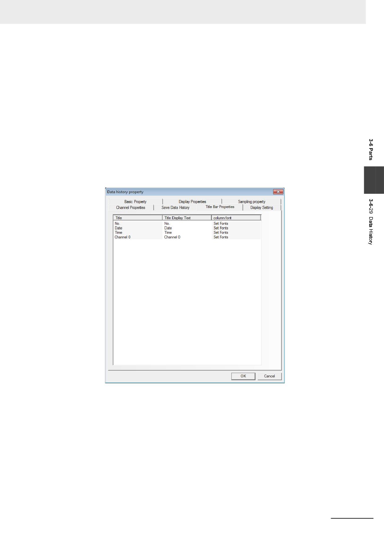
6
Switch to the [Title Bar Properties] tab and make settings of “Title” and “column font” etc.
3
7
Press the [OK] button to complete the setup of the Data History component.
NB-series Programmable Terminals NB-Designer Operation Manual(V106)
3-199
3 Functions of NB-Designer
3-7
Function Parts
3-7-1
Scale
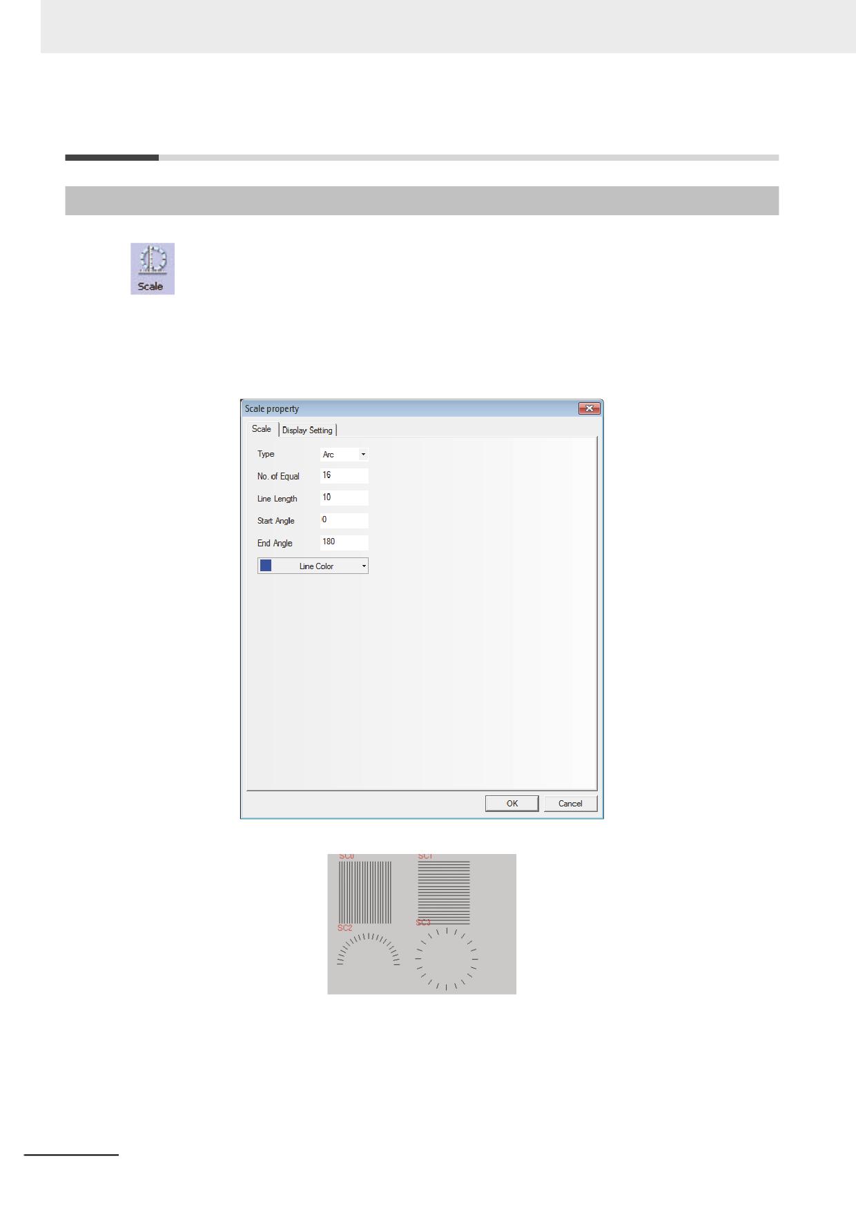
It is applicable to the conditions with the requirement of equal-division notation.
Process of adding one Scale component
1
Press the Scale component icon, drag it to the screen, then the [Scale Property] dialog box will
pop up.
Type: Includes Vertical, Horizontal, Arc and Circularity.
No. of Equal: Set the number of equal-division for the graphics between 2 and 255.
Line Length: Set the length of the scale between 1 and 24.
Start Angle/End Angle: The start angle and the end angle of the arc between 0 and 360
degree.
2
Press the [OK] button to complete the setup.
3-200
NB-series Programmable Terminals NB-Designer Operation Manual(V106)
3 Functions of NB-Designer
3-7-2
Function Key
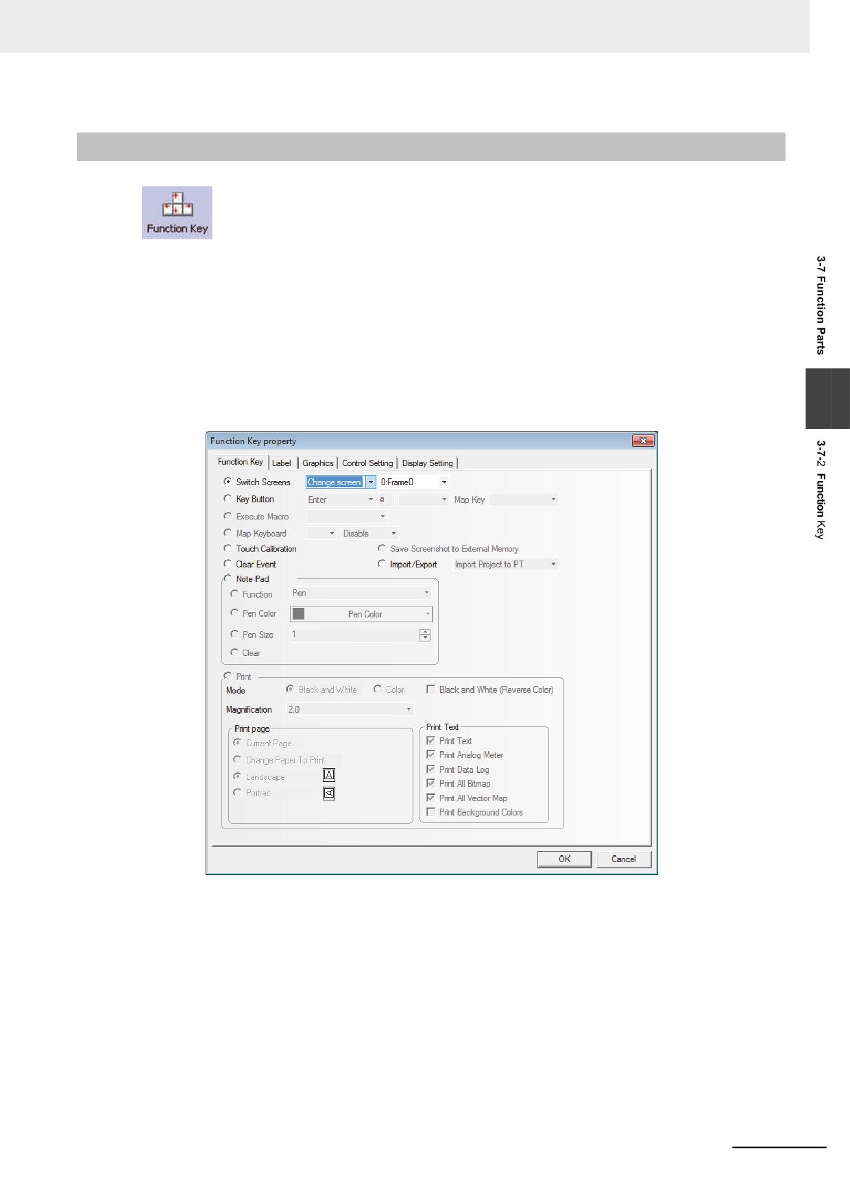
Function Key provides functions such as “Switch Screens”, “Keyboard Function”, “Execute
Macro”, “Touch Calibration”, “Clear Event” and “Message Board” etc. The function key is not controlled
by the memory address, so the execution of specified function needs to be activated by touching this
component.
Process of adding one Function Key
1
Drag the Function Key icon after it is pressed and display “Function Key Property”. In “Function
Key” tab, allocate functions such as “Switch Screens”, “Key Button”, “Execute Macro”, “Touch
Calibration”, “Clear Event”, “Notepad” for each function key. The NB-Series does not support
3
“Print” currently.
2
Go to the [Label] tab and fill in the text to be displayed.
3
Go to the [Graphics] tab and select the Vector Graphics or Bitmap to display the state.
4
Go to the [Control Setting] tab and make the Security Setting and set the Triggering action.
5
Press the [OK] button to adjust the position and size of the Function Key.
NB-series Programmable Terminals NB-Designer Operation Manual(V106)
3-201
3 Functions of NB-Designer
Function Key
1
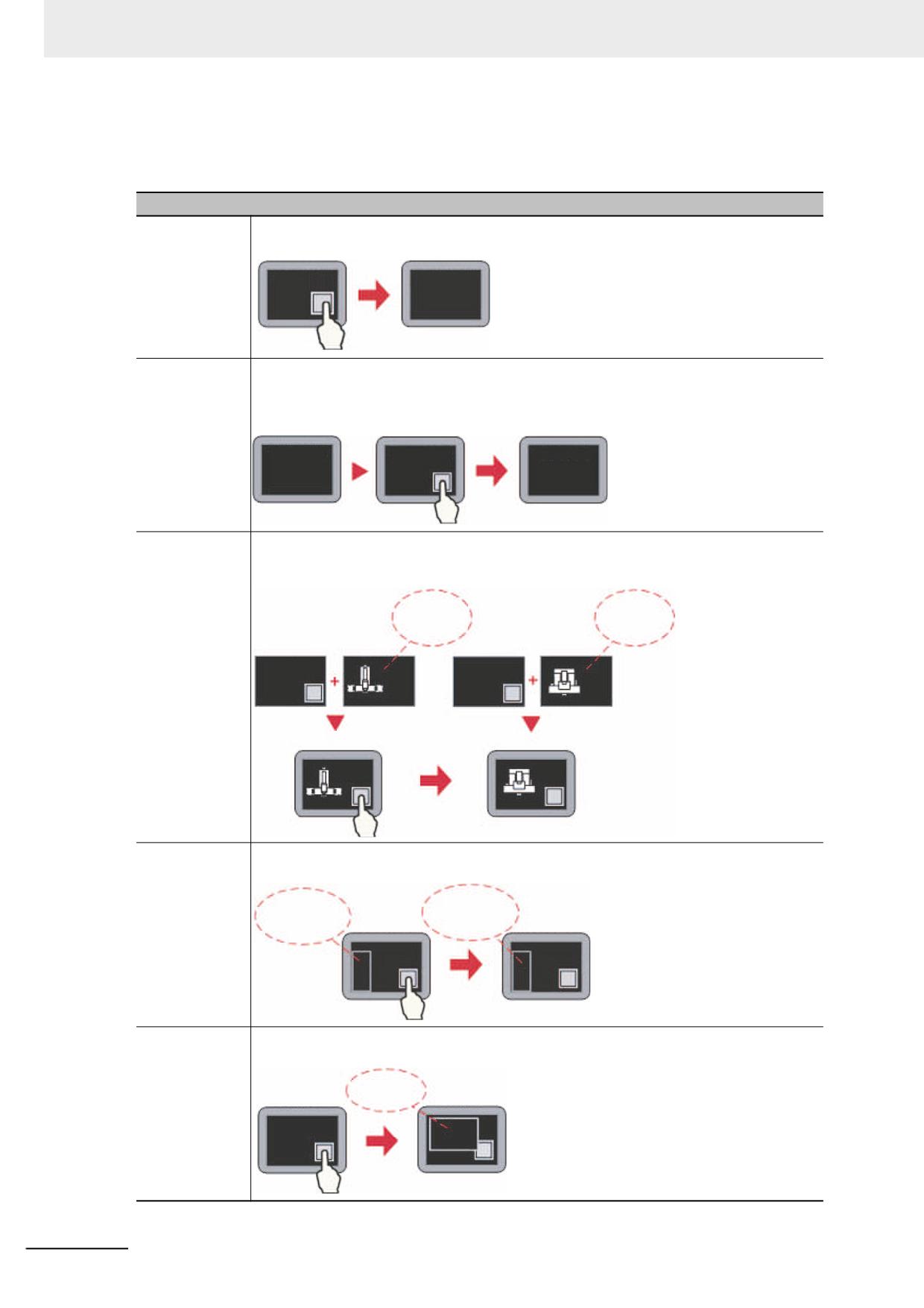
Switch Screen
Descriptions of Switch Screen
Change
Pressing the Function Key will make the current Base Screen including all of the pop-up
Screens
screens closed and the Base Screen with the specified Screen No. will be switched to.
Frame 0
Frame 10
Backward
Pressing the Function Key can make the current Base Screen closed and return to the
latest opened Base Screen, which is effective only for the Base Screen. For example, when
pressing the Function Key in “Frame 10” after “Frame 0” has switched to “Frame 10”,
“Frame 10” will be closed and the Screen will return to “Frame 0”.
Frame 0
Frame 10
Frame 0
Change
After the Function Key is pressed, the Common Sheet (Frame 1 is the system default
Common Sheet
screen.) can be replaced by the specified screen which will become the new Common
Sheet.
Common
Common
Sheet
Sheet
Frame 0
Frame 1
Frame 0
Frame 10
Frame 0
Frame 0
Change Menu
After the Function Key is pressed, the Menu Screen (Frame 2 is the system default screen.)
Screen
can be replaced by the specified screen which will become the new Menu Screen.
Frame2
Frame10
Fast Selection
Fast Selection
Frame 0
Frame 0
Pop-up Screen
After the Function Key is pressed, the specified screen will pop up and be displayed above
the current Base Screen, and the current screen will not be closed.
Pop-up
Frame 0
Screen
Frame 0
3-202
NB-series Programmable Terminals NB-Designer Operation Manual(V106)
3 Functions of NB-Designer
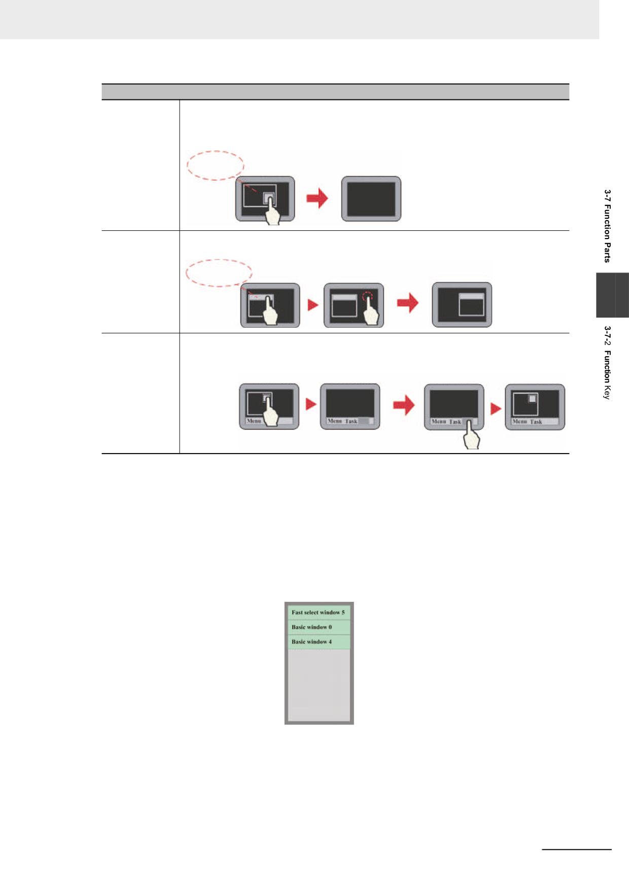
Descriptions of Switch Screen
Close Screen
Closing the Pop-up Screen which is displayed in the screen placed with a function key. The
screen operations with the function do not perform write of the data for the address of
control which is set by the Direct Screen or Indirect Screen. Therefore, make sure that point
when the Direct Screen or Indirect Screen is used.
Pop-up
Screen
Frame 0
Frame 0
Title bar on
Pressing the Function Key can move the Pop-up Screen to the specified position in the
Pop-up Screen
screen, which is effective for Pop-up Screen, Indirect Screen and Direct Screen.
Title Bar
Frame 0
Frame 0
Frame 0
3
Minimize
After the Function Key is pressed, the Pop-up Screen will minimize to the Taskbar. Pressing
this icon will make the screen return to its original position. This function is effective for Pop-
up Screen, Indirect Screen and Direct Screen.
Frame 0
Frame 0
Frame 0
Frame 0
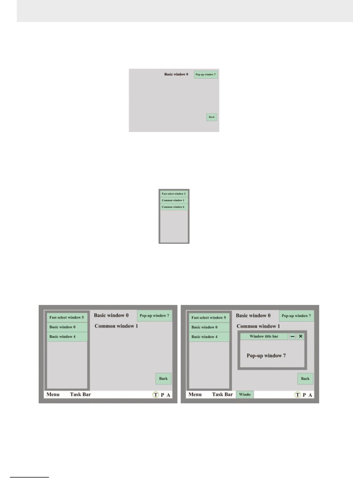
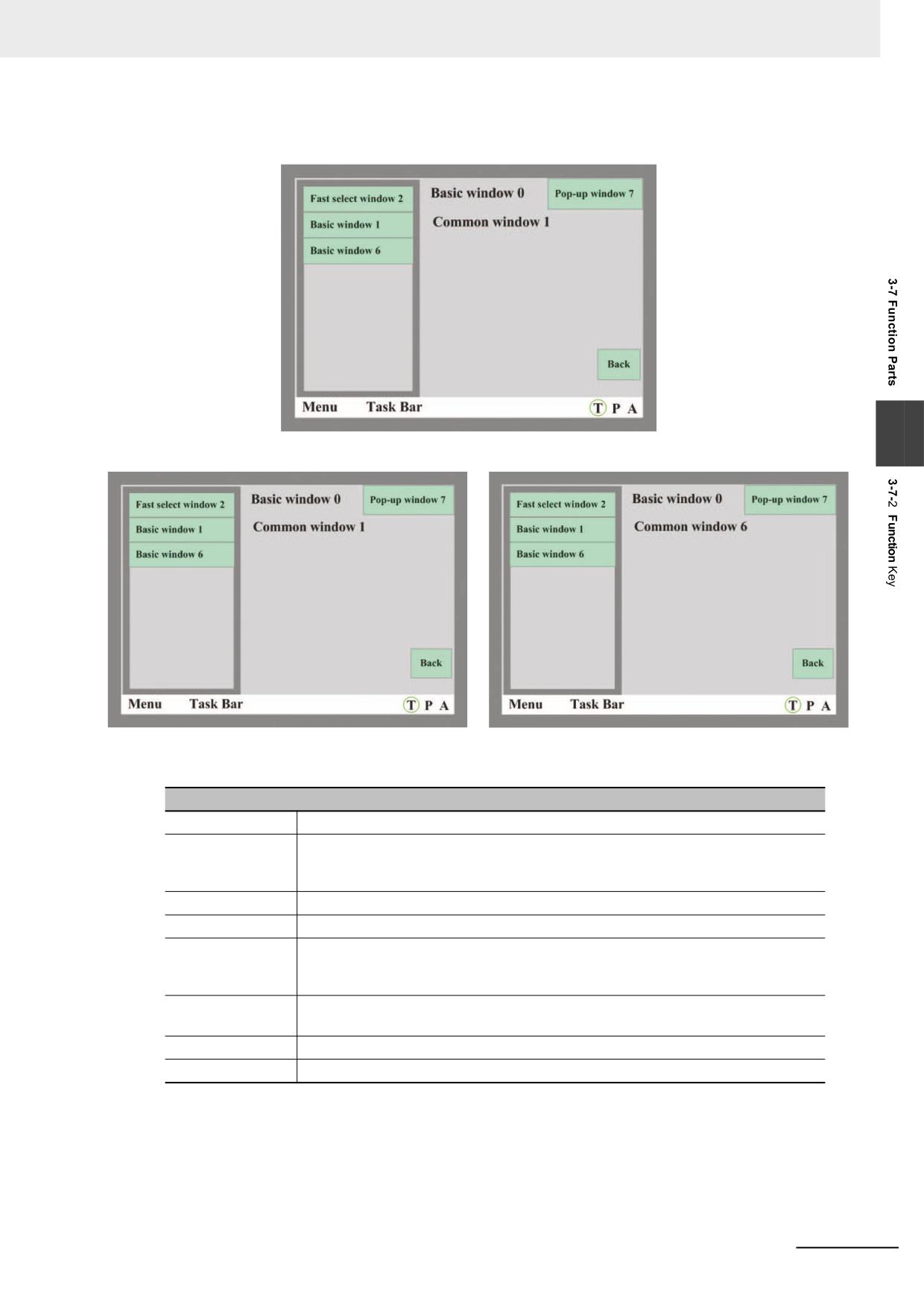
Example: Screen switching function
(1) Create a new project and save it.
(2) Create each of Fast select window 2, Common window 1, Basic window 4, Fast select
window 5, Common window 6, Pop-up window 7. The Fast select window 2 and the Fast
select window 5 are the same size ((100, 220) in this case) and the Pop-up window 7 is the
smaller that other screens (it is ((200,150) in this case).
(3) Create three function keys in the Fast select window 2.
Three function keys such as [Change Screen] function key ti switch to Basic window 0,
[Change Screen] function key to switch Basic window 4, and [Change Menu Screen]
function key to switch to Fast select window 5 to switch the Base Screen shown as below.
(4) Place one text component displaying “Common window 1” displayed in Common window 1.
NB-series Programmable Terminals NB-Designer Operation Manual(V106)
3-203
3 Functions of NB-Designer
(5) Place one text display component to display “Basic window 0” in the Basic window 0 as
below. Also place [Pop-up Screen] function key to display “Pop-up window 7” and
[Backward] function key in the Basic window 0.
(6) Place one Text Display component to display “Basic window 4” and [Backward] function key
in the Basic window 4.
(7) Create three Function Keys in the [Fast select window 5].
Three Function keys such as a [Change Common Sheet] Function Key to switch Common
Sheet into Common window 1, a [Change Common Sheet] Function Key to switch
Common Sheet into Common window 6, and [Change Menu Screen] Function Key to
switch Menu Screen into Fast select window 2 as follows.
(8) Place one Text Display component to display “Common window 6” in the Common window
6.
(9) Place three Function Keys in “Pop-up Screen” in Pop-up window 7. Three Function Keys
such as one [Title bar on Pop-up Screen] Function Key to display “Pop-up window 7”, a
[Minimize] Function Key, and one [Close Screen] Function Key.
(10)After the completion of setup, saving the project file and executing the off-line test after the
compilation, the project is displayed as below.
(11)When switching the “Basic window 0” into “Basic window 4” by the button in Menu Screen,
pressing “Back” button allows the screen returned to “Basic window 0” and then pressing
“Back” button in the Basic window 0 allows the screen returned to “Basic window 4”.
(12)When [Pop-up Screen] is pressed in “Basic window 0”, “Pop-up window 7” will pop up, as
the upper right graphics shown.
3-204
NB-series Programmable Terminals NB-Designer Operation Manual(V106)
3 Functions of NB-Designer
(13)Pressing [Fast selection window 5] in Menu Screen will make the screen switch to Fast
selection window 5, as shown below.
3
(14)Pressing [Common Sheet 1/6] can realized the switching among the Common Sheet.
2
Keyboard Function
Descriptions of keyboard function
Enter
Equivalent to the function of Enter key in the keyboard.
Back Space
When entering numbers or Text strings in the component [Number Input] or the
component [Text Input] by Function Keys, remove one character which is placed
immediately before the input cursor.
Clear
Clears the contents input to “Number Input” and “Text Input” components.
Escape
Cancels the input operation, equivalent to the function of Esc key in the keyboard.
Unicode
Sets the input characters including “0, 1, 2, …” on the number keys, ASCII codes
like a, b, c etc or Unicode characters for “Number Input” and “Text Input”
components.
Cursor
Includes “Up”, “Down”, “Left”, “Right”, “Line head”, “Line tail”, “First position” and
“Last position”.
Select text
Includes “Start selecting” and “Finish selecting”.
Text operation
Includes “Copy”, “Cut” and “Paste”.
NB-series Programmable Terminals NB-Designer Operation Manual(V106)
3-205
3 Functions of NB-Designer
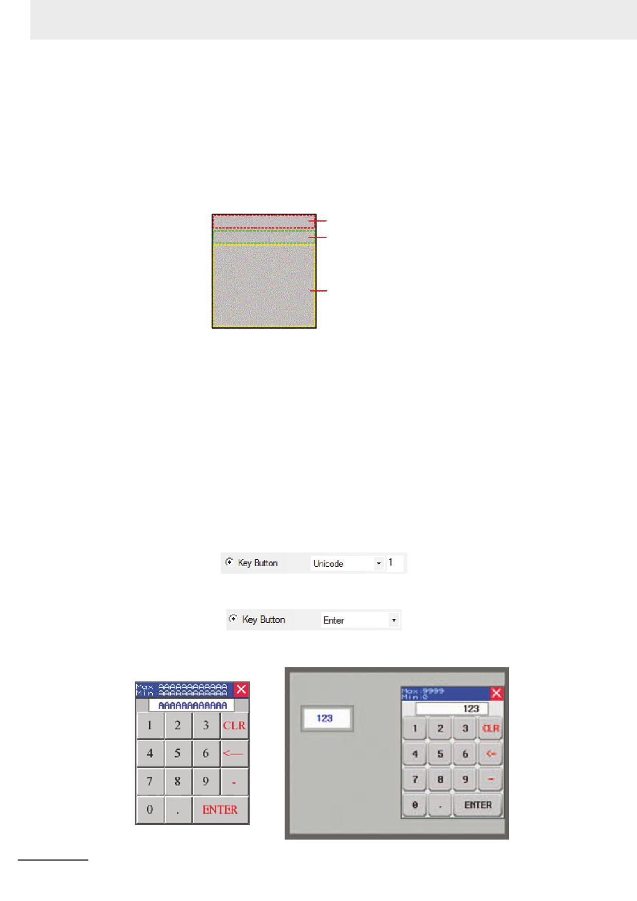
Example: Making NUM Keyboard
Number (0 to 9) keys, Float, Minus sign, Enter, CLR and Backspace keys are required in the
keyboard.
Step 1: Create a new project and make the layout of the NUM keyboard.
Firstly add the new screen “Frame 10” and open [Screen Property], then perform the screen
operations such as setting the Width, Height and the border width to be 160, 200 and 2
respectively, setting the Frame Color, checking [Screen Attribute] and setting it to be “Keyboard
page”. Finally divide Frame10 into three areas, i.e. Screen control area, Input Display area and
Keyboard area, as shown below.
Screen control area
Display area
Keyboard area
Step 2: Add the required components for the keyboard.
(1) Firstly, add one Function Key as screen title bar into the Screen control area, in this case,
select “Title bar on Pop-up Screen”.
(2) Add two Text Display components for displaying the ranges of the maximum and the
minimum for the Number Input, where the [Read Address] are LW9180 (LW9180 ~ LW9187
is the system special memory for displaying the maximum of Number Input) and LW9190
(LW9190 ~ LW9197 is the system special memory for displaying the minimum of Number
Input) respectively and [Word Length] are both 6.
(3) Add one Function Key to close keyboard screen, i.e. to check [Key Button] and select
“Escape”.
(4) Add one Text Display component to input display box in the Display area with [Read
Address] set to LW9070 (LW9060 ~ LW9075 is the special memory which works as the
buffer of Number Input or Text Display Input.) and [Word Length] set to 6.
(5) Add twelve Function Keys as Character Input Keys in the Keyboard area. Take an example
to input [1]: Select “Unicode” after selecting [Keyboard Function], then input “1” in Input
area. And the operation for the other characters is similar to this operation.
Add three Function Keys as the special keys, i.e. select “Clear”, “Backspace” and “Enter”
respectively after selecting [Key Button] for the three Function Keys.
The final effects of the editing screen and the test are shown as the lower left and lower right
graphics respectively.
3-206
NB-series Programmable Terminals NB-Designer Operation Manual(V106)
3 Functions of NB-Designer
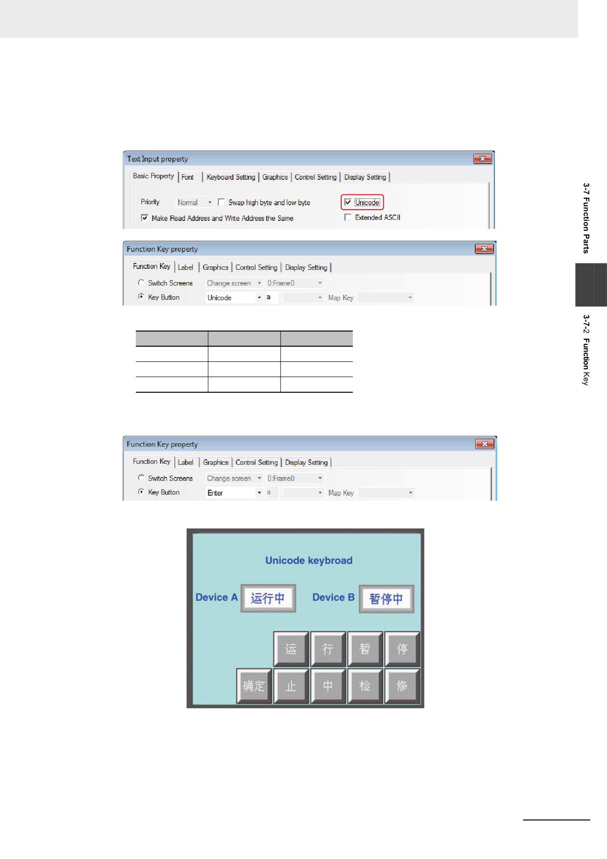
Example: Create Unicode keyboard by the combination of Text Input and Function Key.
The Unicode keyboard can be created by using [Unicode] option, which is available in the
related Property screen of Text Display component, Text Input component and Note Book
component, in combination with the [Key Button] - [Unicode] option in the Function Key
Property.
3
(1) Make the following settings after adding two Text Input components.
Properties
Text Input A
Text Input B
Unicode
Unicode
Unicode
Address
LW0
LW3
Word Length
3
3
(2) Add the Function Key and set the character to be input.
(3) Add one [Enter] key, i.e. select “[Key Button] - [Enter]” in the “Key Button” tab.
(4) The final effect is as shown below.
Unicode function currently only supports Chinese, English, Japanese and the common
symbols.
NB-series Programmable Terminals NB-Designer Operation Manual(V106)
3-207
3 Functions of NB-Designer
3
Execute Macro
After this function is selected, pressing the Function Key can execute the specified existing
Macro code. (Refer to 3-9-3 Macro Triggering (Page 3-273))
4
Touch Calibration
After this function is selected, pressing the Function Key can make the system go to PT Touch
Calibration Screen, thus allowing the users to perform touch calibrations to the PT.
5
Clear Event
After this function is selected, pressing the Function Key can clear the event information stored
in the recipe memory.
6
Notepad
Functions of Message Board
Function
Pen
Pressing the Function Key means the current function is the pen in
the Notepad.
Eraser
Pressing the Function Key means the current function is the eraser in
the Notepad.
Clear
Pressing the Function Key can clear the contents in the area selected
Block
by the mouse of the Notepad.
Pen Color
For setting the pen color.
Pen Size
For setting the pen size from the eight size available.
Clear
Removing all the contents in the Notepad.
For the procedures of operation method about the Notepad, refer to 3-7-7 Notepad (Page 3-
220).
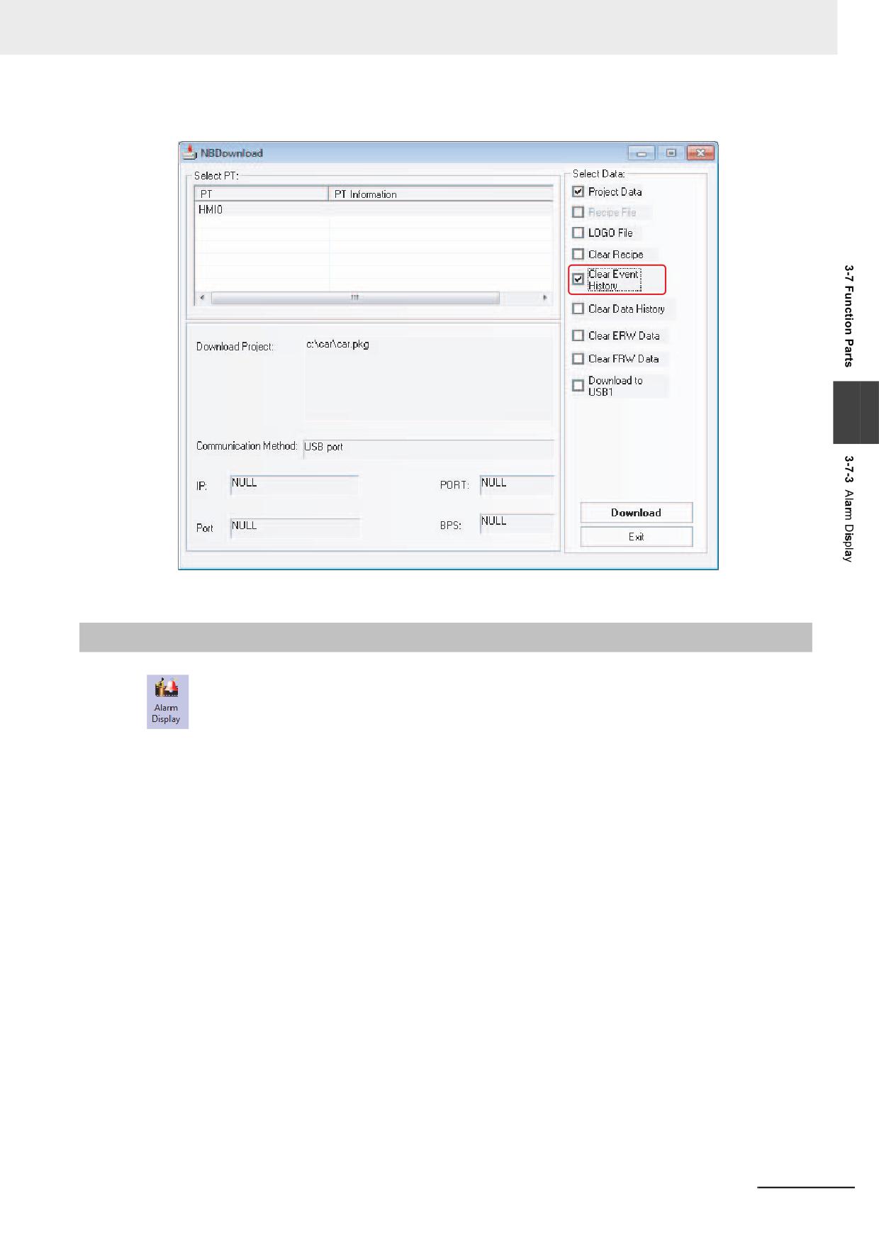
There are four methods to clear the event information:
(a) By clicking the [Function Key] component to clear the event information after the [Clear Event]
option in [Function Key] tab in Function Key Property dialog box being checked. The event
information data stored in the recipe memory can be cleared by this method.
(b) By restarting the PT to clear the event information after the value of special system memory
LW10015 being set to 0. The event information data stored in the recipe memory can be cleared by
this method.
(c) Check in the [Clear Event History] option in [NBManager] dialog box and execute the download,
the event information will be cleared. The event information data stored in the recipe memory and
the event information files stored in the external memory can be cleared simultaneously by this
method.
(d) Check in the [Clear Event History] option in the NBDownload dialog box and execute the download
again. The event information data stored in the recipe memory and the event information files
stored in the external memory can be cleared simultaneously by this method, as shown below:
3-208
NB-series Programmable Terminals NB-Designer Operation Manual(V106)
3 Functions of NB-Designer
3
3-7-3
Alarm Display
Alarm Display icon can be used to display the triggered preset alarm information by using the
Neon Lamp in the area where the Alarm Display locates. The alarm information must be related to node
address of a certain bit, and it will scroll from the right to the left when the bit address is triggered to the
alarm state. The alarm information will continue to scroll until this bit address is switched to the non-
alarm state. The alarm information must be logged in the [Alarm Setting] database in advance. (This
component only displays the alarm information, and the component to be displayed must be logged in
the [Alarm Setting] database).
NB-series Programmable Terminals NB-Designer Operation Manual(V106)
3-209
3 Functions of NB-Designer
Process of adding one Alarm Display
1
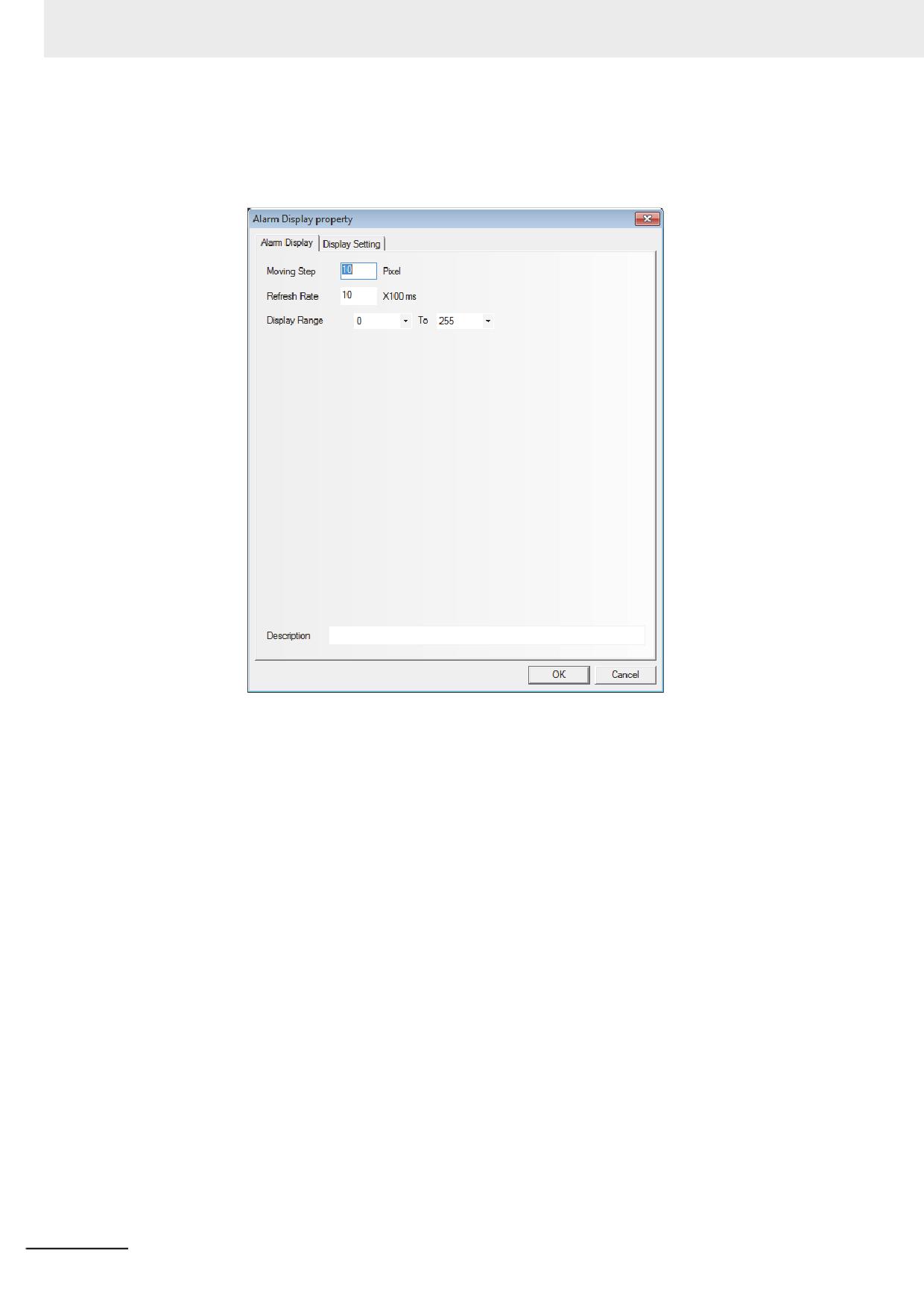
Press the Alarm Display icon, drag it to the screen, then the [Alarm Display Property] dialog
box will pop up.
Moving Step: Set the Moving Step in the unit of pixel. The larger the number of moving step,
the faster the speed of scroll display. The value is between 1 and 255.
Refresh Rate: Refers to the interval of each movement with the unit of 100 ms. The larger the
value of moving speed, the slower the speed of scroll display. The value is
between 1 and 10000 (i.e. 0.1 s to 1000 s).
Display Range: Set the range of alarm types to be displayed between 0 to 255. Restricting the
alarm types at this moment allows the display only optional alarm information.
Description: The descriptions can be entered to explain the Alarm Display components (the
descriptions will not be displayed in PT screen.).
2
Press the [OK] button to complete the setup.
3-210
NB-series Programmable Terminals NB-Designer Operation Manual(V106)
3 Functions of NB-Designer
Example of creating one Alarm Display component
1
Create a new project firstly.
2
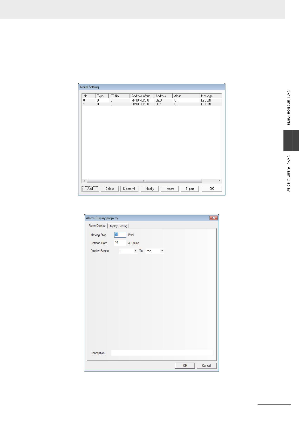
Click the [Alarm Setting] icon in [Project Database] to display the logon list of alarm setting, and
then add two pieces of alarm setting, as shown below.
3
3
Add one Alarm Display component in Frame 0.
NB-series Programmable Terminals NB-Designer Operation Manual(V106)
3-211
3 Functions of NB-Designer
4
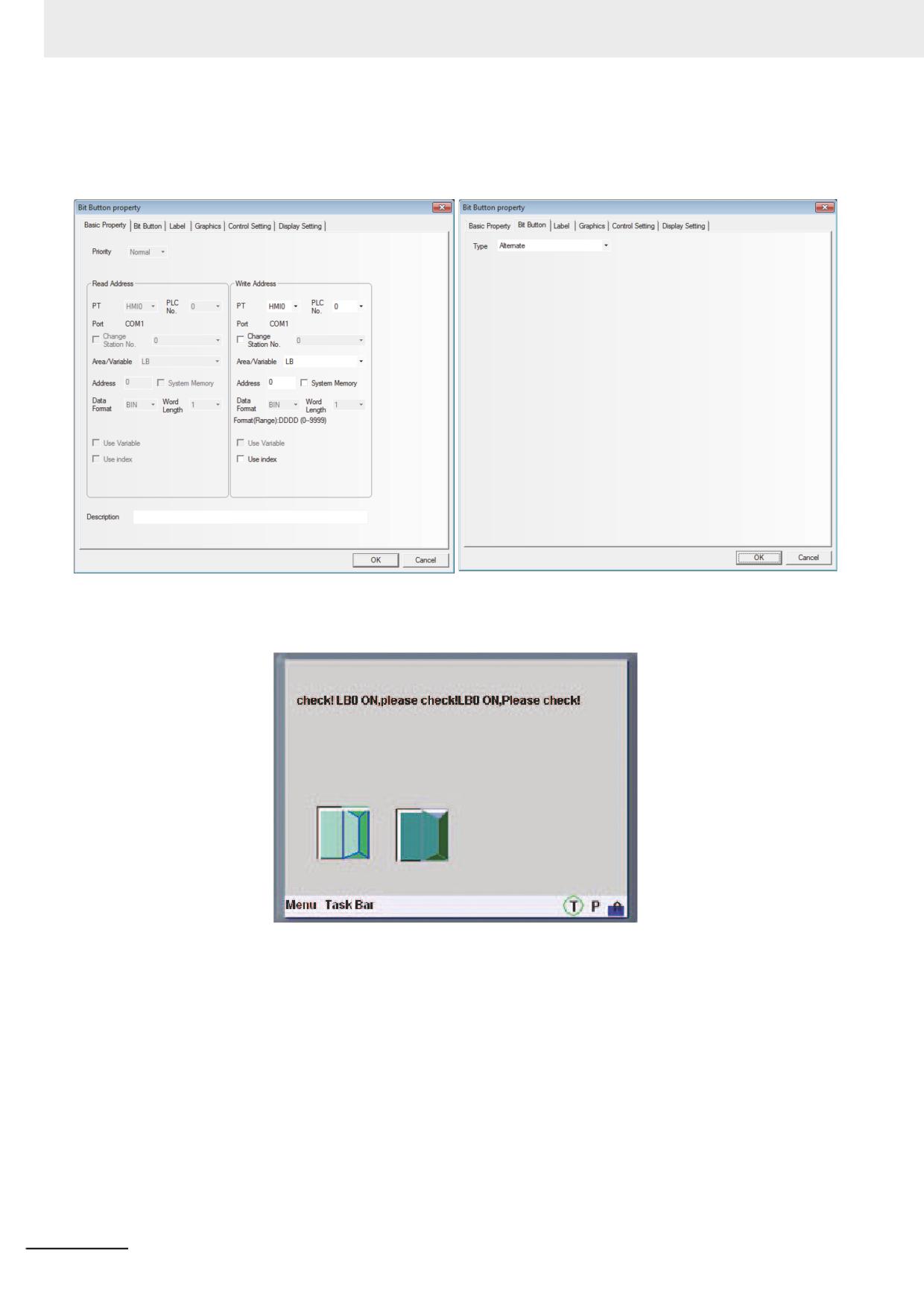
Add two Bit Switches to control the ON/OFF of LB0 and LB1 respectively, then switch the
ON/OFF state of the LB0 and LB1, the alarm setting which was registered by the procedure 2
can be switched between display and non-display by the alarm display.
5
When saving the project files and executing the offline test after the compilation, the result will
be displayed as follows.
3-212
NB-series Programmable Terminals NB-Designer Operation Manual(V106)
3 Functions of NB-Designer
3-7-4
Timer
Timer is a kind of component performing the timing. When the timing is over, it will play the
other corresponding functions such as periodical Macro instruction execution, parameter setting and
data transmission etc.
Process of adding the Timer
1
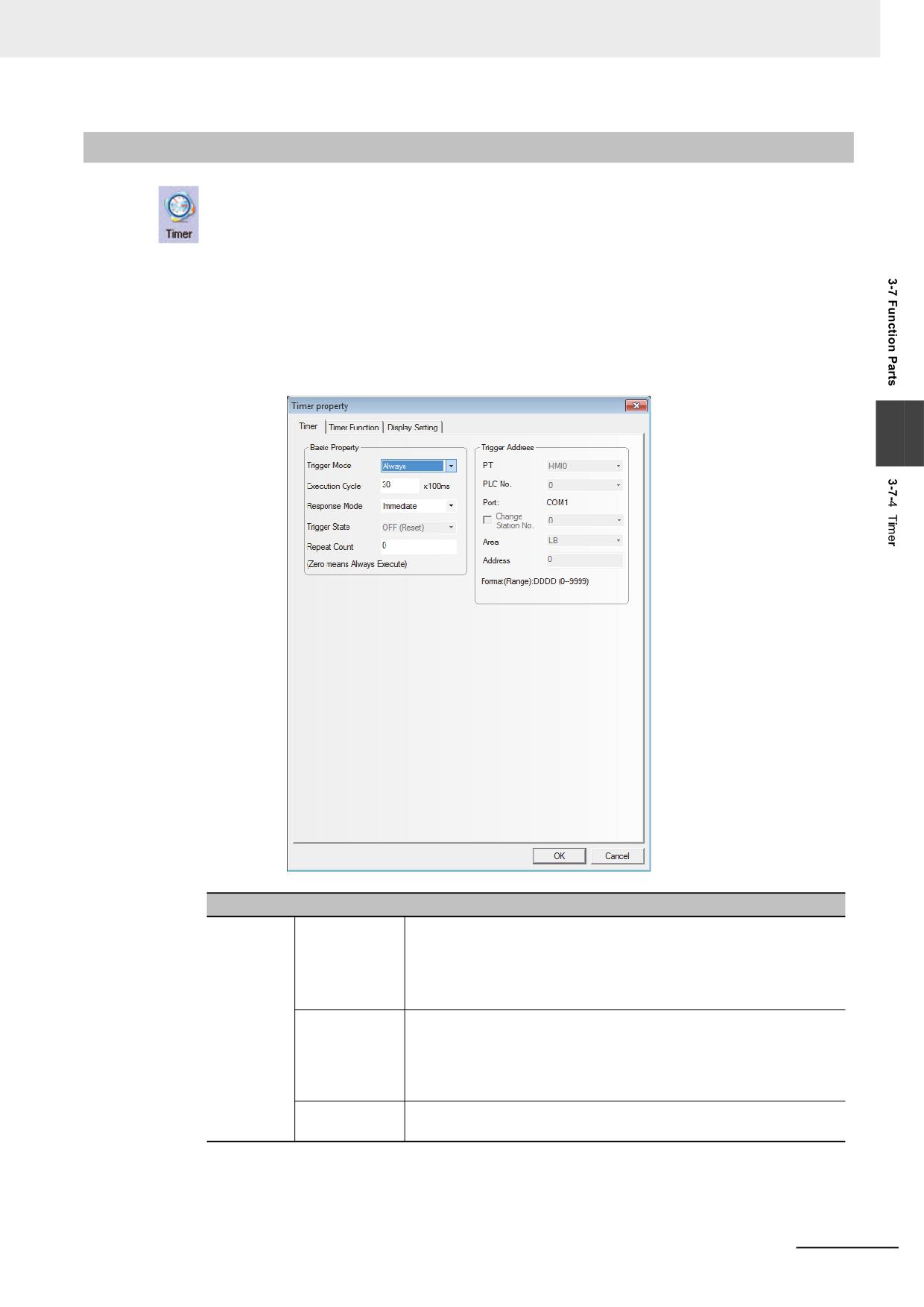
First press the Timer icon before dragging it into the screen, and go to [Timer] tab after the
[Timer Property] dialog box pops up.
3
Descriptions of Timer Properties
Trigger
Always
With this triggering mode, the timer will be triggered once it is
Mode
initialized. The timer will be operated when displaying the screen in
the timer was loaded to, and the timer will be stopped automatically
and will not be triggered any more when the number of the timer
trigger operations reaches to the value specified at “Repeat Count”.
When screen is
The timer will be operated when the timer is placed in the screen and
loading
the number of the timer trigger operations it will stop automatically
after the value set in “Repeat Count” being reached, and will not be
triggered any more. The effect of this function is almost the same as
that of “All time”.
When screen is
Function operation will be triggered once when the screen where the
unloading
timer component locates is closed.
NB-series Programmable Terminals NB-Designer Operation Manual(V106)
3-213
3 Functions of NB-Designer
Descriptions of Timer Properties
Trigger
Trigger
When the address specified at [Trigger Address] matches to the
Mode
Address
status specified at [Trigger State], the triggering operates. If [Repeat
Count] is set to “0”, the triggering operation is consecutively repeated
until the trigger condition is released. After the trigger condition is
cleared once, followed by the trigger is operated for the number of
times specified at [Repeat Count], the timer will be stopped
automatically.
Execution
It refers to the timing cycle of the timer with the unit of 100 ms. The timer will perform
Cycle
functional operation once at each interval of timing cycle.
Response
Immediate
When the triggering condition is met, the function will be executed
Mode
immediately.
Delay
When the triggering condition is met, the function will be executed
after one cycle is delayed.
Trigger
When “Trigger Address” is selected, the triggering state of the memory is On or Off.
State
Repeat
It refers to the times of repeated execution after the timer is triggered. When it is “0”, the
Count
function will always be executed.
Trigger
After “Trigger Address” is selected, it needs to specify the address to be the trigger.
Address
2
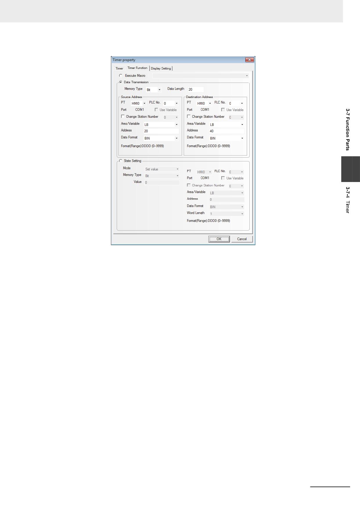
Switch to the [Timer Function] tab:
Execute Macro: The Macro code to be executed for each timing reached to the time set by the
executing cycle. (Refer to 3-9-3 Macro Triggering (Page 3-273))
Data Transmission: The data transmission will be performed. The data will be transformed
from the specified addresses as ([Source Data]) to the specified
addresses as ([Destination Address]) for each timing reached to the time
set by the executing cycle.
Source Address: Refers to the starting address that the data will be transferred from.
Destination Address: Refers to the starting destination address that the data will be transferred to.
Memory Type: Used to select among “Word” or “Bit” for the memory type to be transmitted.
3-214
NB-series Programmable Terminals NB-Designer Operation Manual(V106)
3 Functions of NB-Designer
Data Length: Refers to the length of the data to be transferred.
3
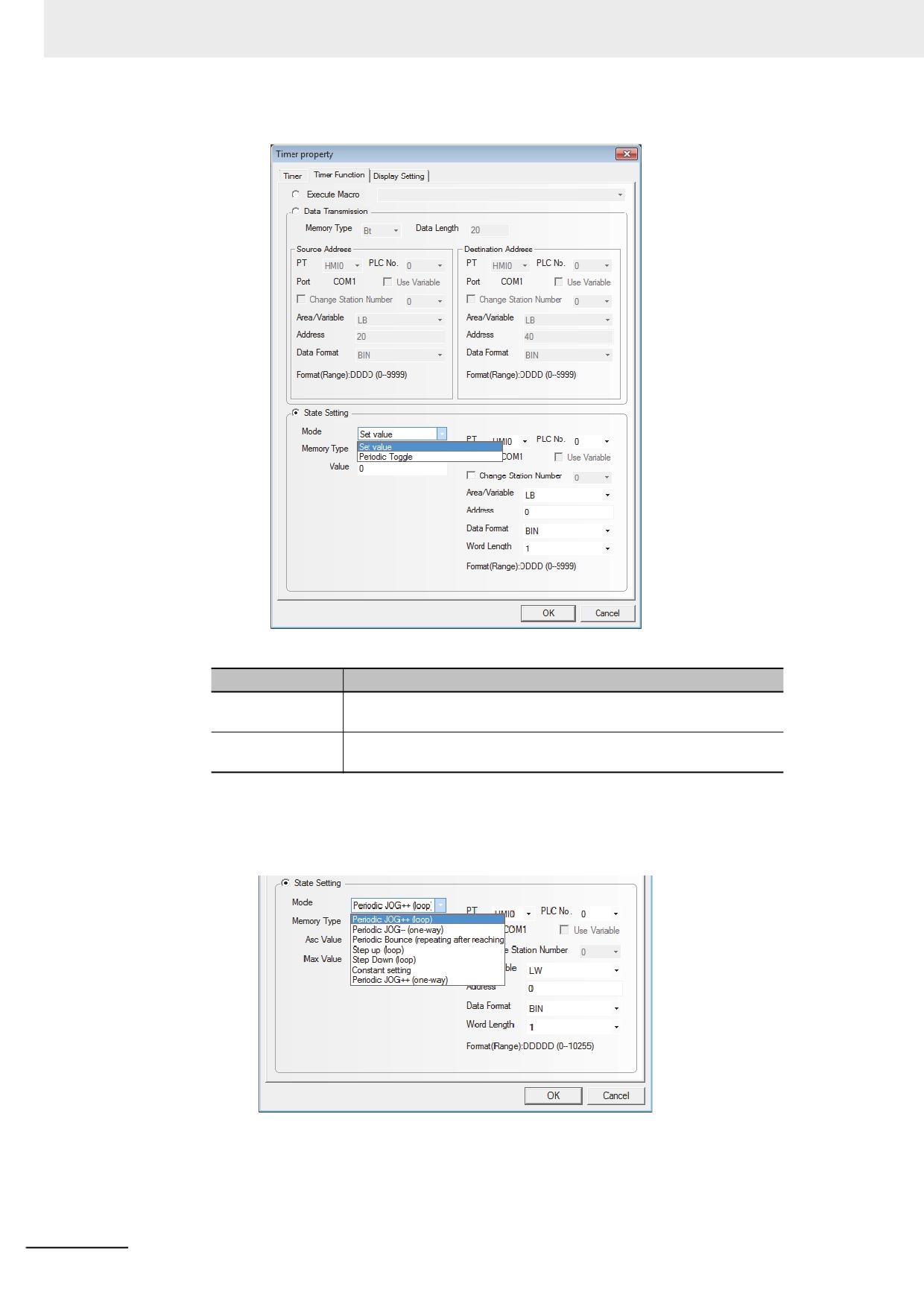
State Setting: After the time set at Execution cycle passed, when the value is written to the bit
address or word address, select the parameter.
Set Address: After the time which was set at Execution cycle passed, specify the bit address or
word address to be written.
(a) Bit Address Setting ([Memory Type] is specified to [Bit]):
NB-series Programmable Terminals NB-Designer Operation Manual(V106)
3-215
3 Functions of NB-Designer
Mode: Includes Set value, Periodic Toggle, as shown below.
The detailed description of each function is as follows.
Mode
Descriptions
Set Value
After the time which was set at Execution cycle passed, specify the
value of the bit address to “0” or “1”.
Periodic Toggle
After the time which was set at Execution cycle passed, switch the
value of the bit address “0” with “1”
(b) Word Address Setting([Memory Type] is set to [Word]:
Mode: Periodic JOG++(loop), Periodic JOG--(one way), Periodic Bounce(repeating
after reaching), Step up(loop), Step Down(loop), Constant Setting, and Periodic
JOG++(one-way) as shown below.
3-216
NB-series Programmable Terminals NB-Designer Operation Manual(V106)
3 Functions of NB-Designer
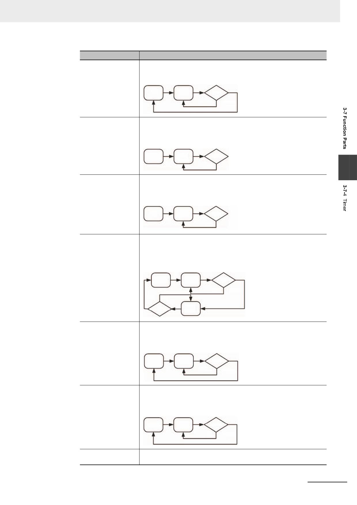
Mode
Descriptions
Periodic
This mode makes the address value of the memory for the specified word
JOG++(loop)
increase automatically by the “increment” at the interval of each “Execution
Cycle” and makes it return 0 again when “the upper limit value” is reached.
T
0
V+K
Upper
NO
YES
Periodic
This mode makes the address value of the memory for the specified word
JOG--(one-way)
decrease automatically by the “decrement” at the interval of each “Execution
Cycle” and makes it stop at the lower limit value after “the lower limit value” is
reached.
T
Upper
V-K
Lower
NO
3
Periodic
This mode makes the address value of the memory for the specified word
JOG++(one-way)
increase automatically by the “increment” at the interval of each “Execution
Cycle” and makes it stop at the upper limit value after “the upper limit value”
is reached.
T
0
V+K
Upper
NO
Periodic Bounce
This mode makes the address value of the memory for the specified word
(repeating after
increase automatically by the “step” at the interval of each “Execution Cycle”
reaching)
until to “the upper limit value”, and then makes it decrease by the “step” at
the interval of “Execution Cycle” until to the “lower limit value”, and later
makes it increase again, thus making the cycle repeated again and again.
T
Lower
V+K
Upper
NO
YES
YES
NO
Lower
V-K
Step up (loop)
This mode makes the address value of the memory for the specified word
increase automatically by the “step” at the interval of each “Execution Cycle”
until to “the upper limit value”, and makes it increase again after being reset
to “the lower limit value”.
T
Lower
V+K
Upper
NO
YES
Step down (loop)
This mode makes the address value of the memory for the specified word
decrease automatically by the “step” at the interval of each “Execution Cycle”
until to “the lower limit value”, and makes it decrease again after being reset
to “the upper limit value”.
T
Upper
V-K
Lower
NO
YES
Constant Setting
The preset constant value will be written to the address of the memory for the
specified word after the “Execution Cycle” is reached.
NB-series Programmable Terminals NB-Designer Operation Manual(V106)
3-217
3 Functions of NB-Designer
3-7-5
Bitmap
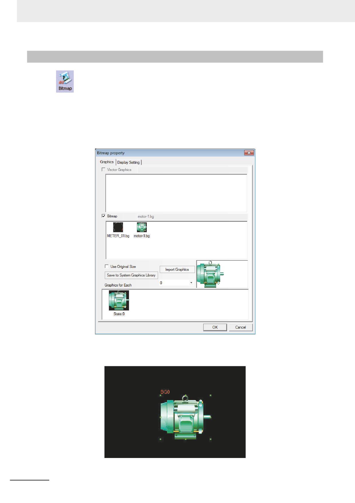
Bitmap component is used to call and display the bg-form graphics registered in the system
graphics library or the graphics library in Project File Window. Bitmap component is not controlled by
the memory, and doesn’t have multiple states, thus the bitmap corresponding to the graphics state
specified by you at the designing time will always be displayed. For the creation and usage of bitmap,
refer to [3-5-6 Bitmap].
1
First press the Bitmap icon, drag it to the screen, then select the bitmap you want to use, as
shown below.
2
Press the [OK] button, and then adjust the position and the size of the Bitmap in the screen, as
shown below:
3-218
NB-series Programmable Terminals NB-Designer Operation Manual(V106)
3 Functions of NB-Designer
3-7-6
Vector Graphics
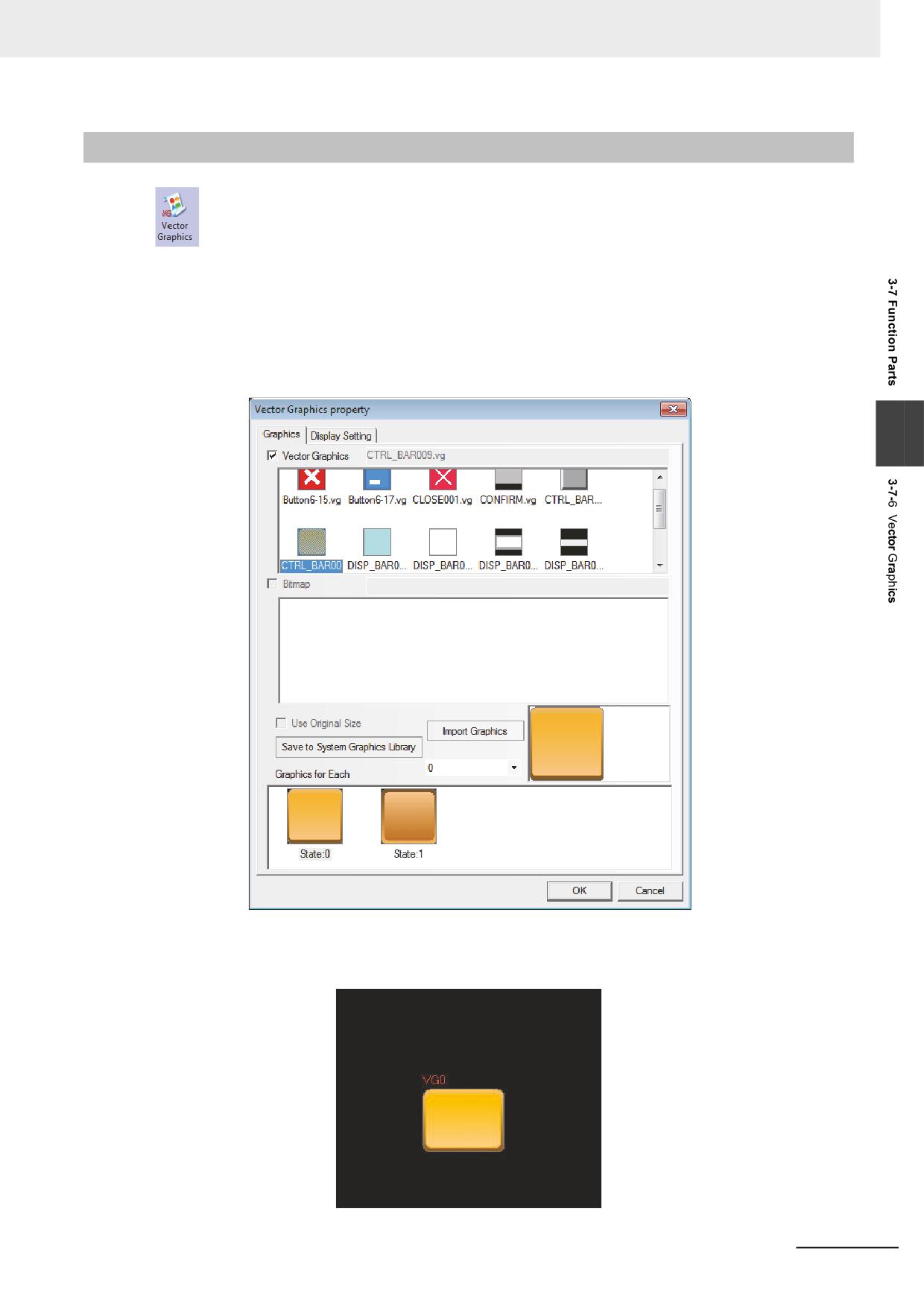
Vector Graphics component is used to call and display the vg-form graphics registered in the
system graphics library or the graphics library in Project File Window. The Vector Graphics component
is not controlled by the memory, and doesn’t have multiple states, thus the Vector Graphics
corresponding to the graphics state specified by you at the designing time will always be displayed. For
the creation and usage of Vector Graphics, refer to [3-5-5 Vector Graphic].
1
Press the Vector Graphics icon, drag it to the screen, then select the Vector Graphics you want
to use, as shown below.
3
2
Press the [OK] button, and then adjust the position and the size of the Vector Graphics in the
screen, as shown below:
NB-series Programmable Terminals NB-Designer Operation Manual(V106)
3-219
3 Functions of NB-Designer
3-7-7
Notepad
Notepad is designed specially to provide the users with a space for the message reservation
and transmission, thus allowing the users to write any text on the PT freely. And its function is similar to
that of the drawing board.
Process of adding Notepad
1
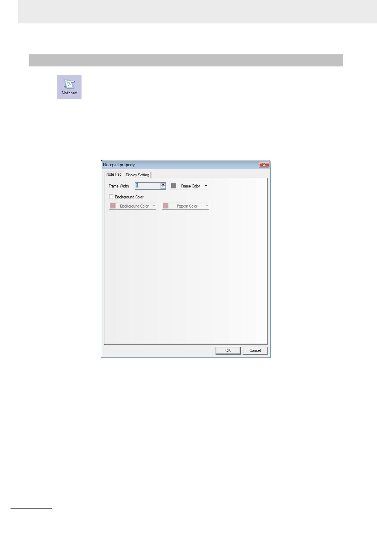
Press the Notepad icon, drag it to the screen, then the [Notepad Property] dialog box will pop
up.
Frame Width: Refers to the frame width of the Notepad.
Background Color: Selects the Background Color and Pattern Color.
2
Press the [OK] button to complete the setup, and adjust the position and size of the Notepad
component.
3-220
NB-series Programmable Terminals NB-Designer Operation Manual(V106)
3 Functions of NB-Designer
The combined use of Notepad with Function Keys
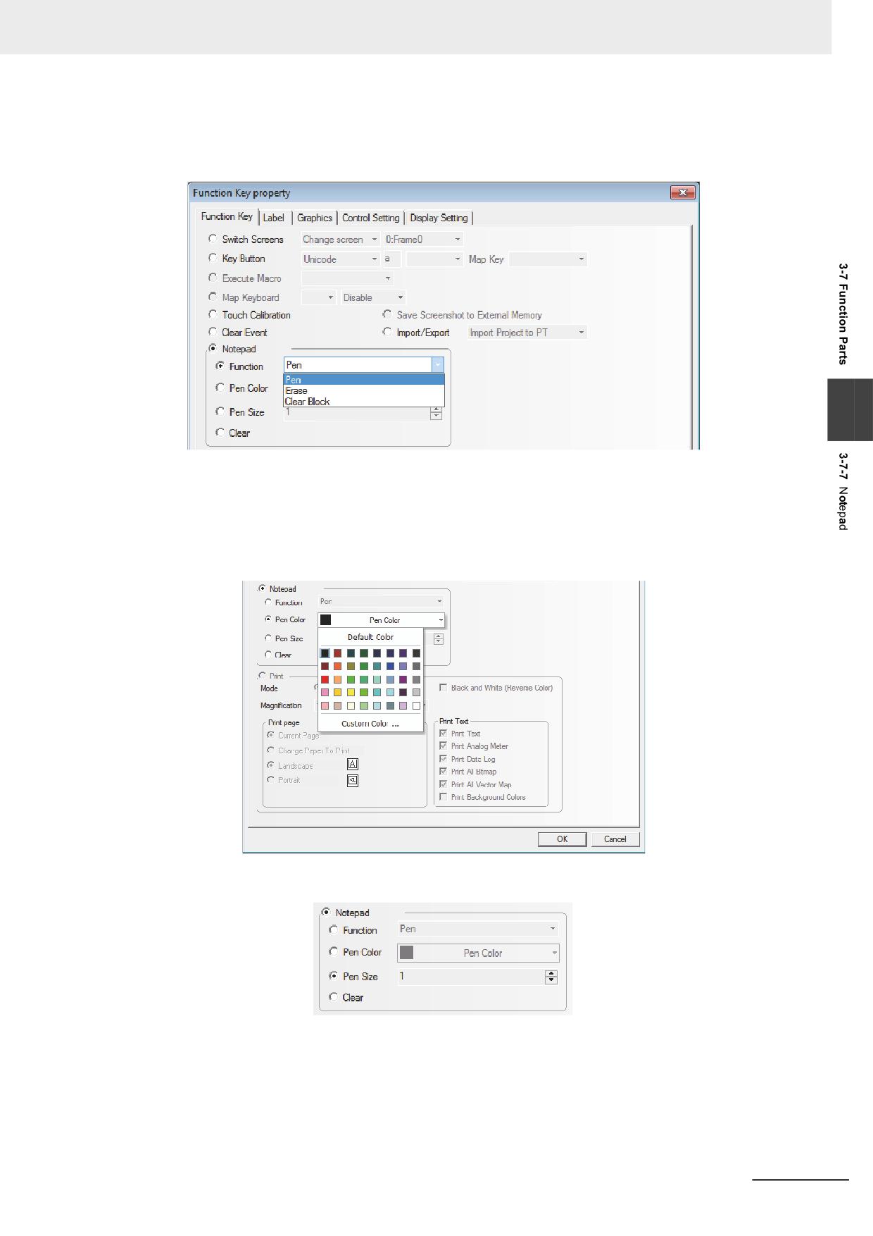
After the Notepad is placed well, you can set the Function, Pen Color, Pen Size and Clear after the
[Notepad] is selected in the Function Key tab, as shown below.
3
(a) Function
Pen: After selecting the pen, you can leave messages or make drawings in the Notepad.
Eraser: Clears the contents in the Notepad.
Clear Block: Clears the contents in the selected area of the Notepad.
(b) Pen Color: Sets the pen color, as shown below.
(c) Pen Size: Sets the thickness of pen from the available 1 (the thinnest) to 8 (the thickest), as shown
below.
(d) Clear: Clears the contents in the whole Notepad.
NB-series Programmable Terminals NB-Designer Operation Manual(V106)
3-221
3 Functions of NB-Designer
Create a Notepad
1
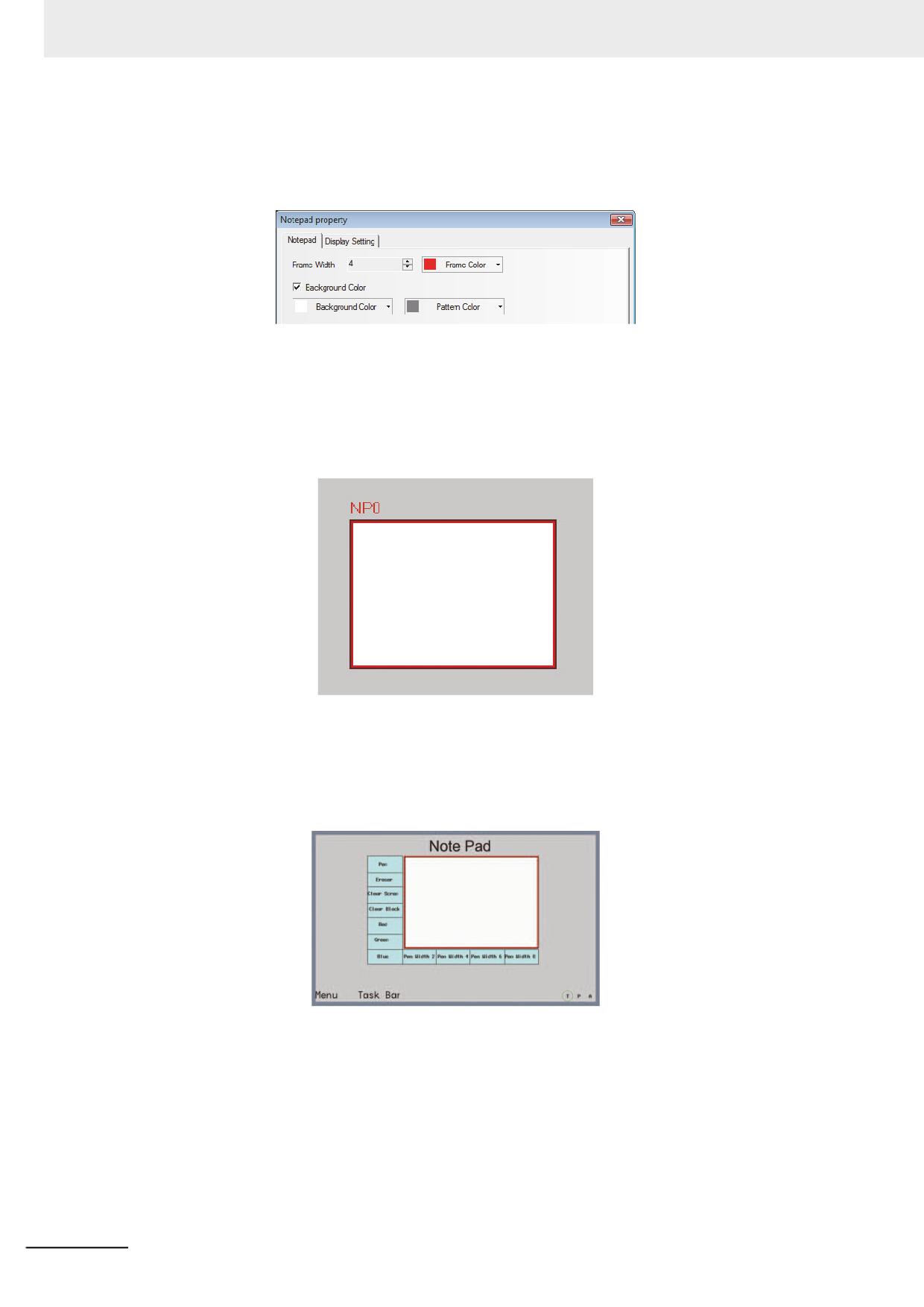
Makes Frame 0 as the Note pad screen. Of course you can make the other screen as the Note
pad screen. And later you just need to drag the Notepad component to the screen.
2
Firstly set the Properties of the Notepad component, as shown below.
Frame Width: Select 4 here from the range of 1 to 16.
Frame Color, Background Color and Pattern Color: Select the colors you want to use here.
3
Then adjust the screen to the required size, as shown below.
4
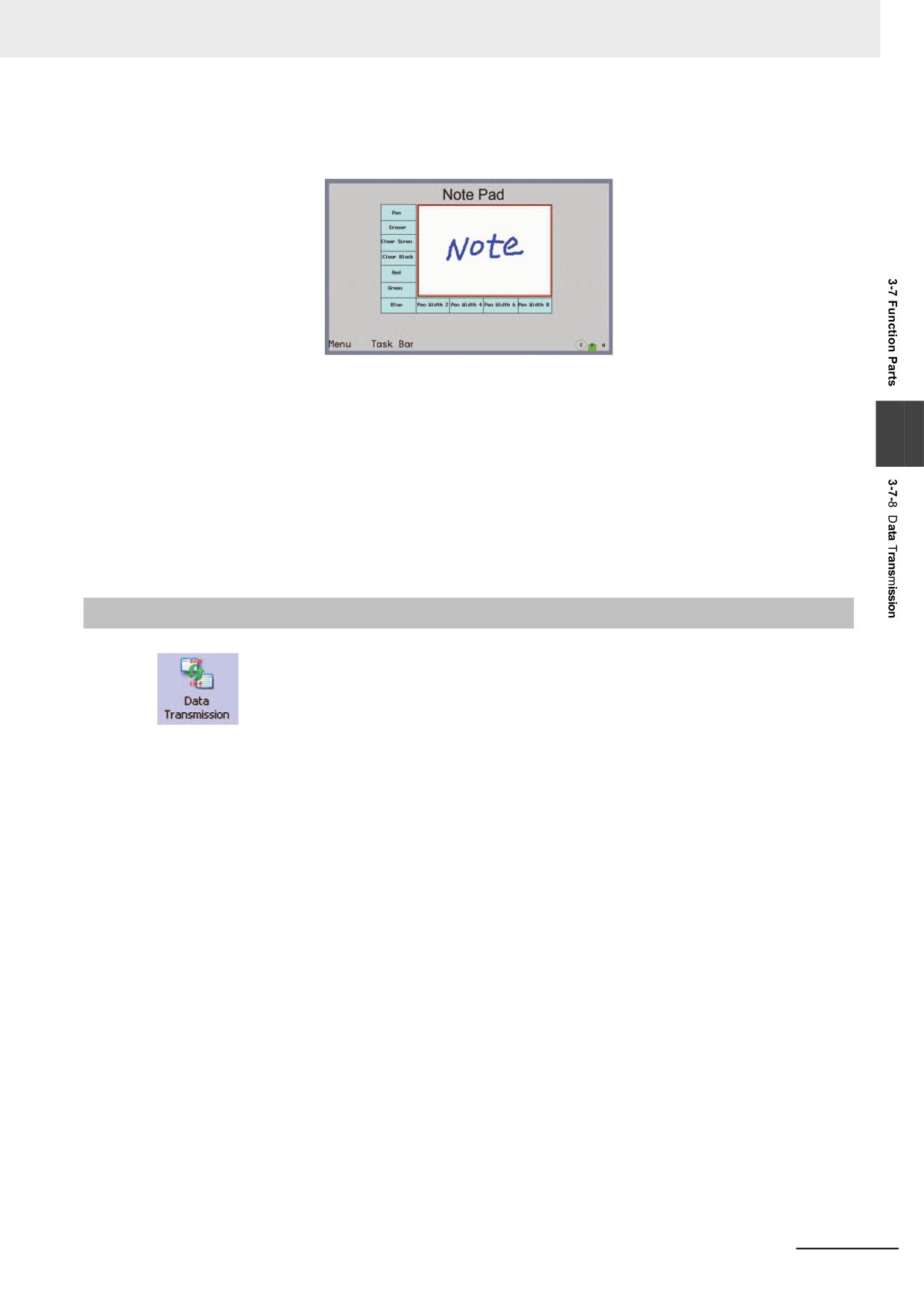
Later add several Function Keys in the left and bottom of the Notepad component respectively,
i.e. select Function Keys FK0, FK1, FK2 and FK3 to be as Pen, Eraser, Clear Block and Clear
Screen respectively, select the Function Keys FK4, FK5, and FK6 to be the Pen Colors of Red,
Green and Blue respectively, and select the Function Keys FK7, FK8, FK9 and FK10 to be the
Pen Sizes of 2, 4, 6 and 8 respectively, as shown below:
3-222
NB-series Programmable Terminals NB-Designer Operation Manual(V106)
3 Functions of NB-Designer
5
[Save] and [Compile] the project files and execute [Offline Test] and result in the display as
follows.
The system reserves the following areas for the system memory:
• LB9020 to LB9032: [Pen], [Eraser], [Clear Block],
• LB9030 to LB9032: pen size,
3
• LW9006 : operation mode of Notepad,
• LW9007 : pen size
• LW9008 : color of pen selecting among 256 colors.
For the details, refer to 3-11 Address of System Memory (Page 3-327).
Note 1
Each PT can only use one Notepad component. If there are more than one Notepad components, an error
occurs at the compilation.
2
The data in the Notepad will not be saved, i.e. be lost, when the power of PT is OFF.
3-7-8
Data Transmission
Data Transmission component can make the data in the specified memory address
transferred to the other memory address. Data Transmission can be triggered by the manual touching
method or the state change of the specified address.
NB-series Programmable Terminals NB-Designer Operation Manual(V106)
3-223
3 Functions of NB-Designer
Process of adding Data Transmission
1
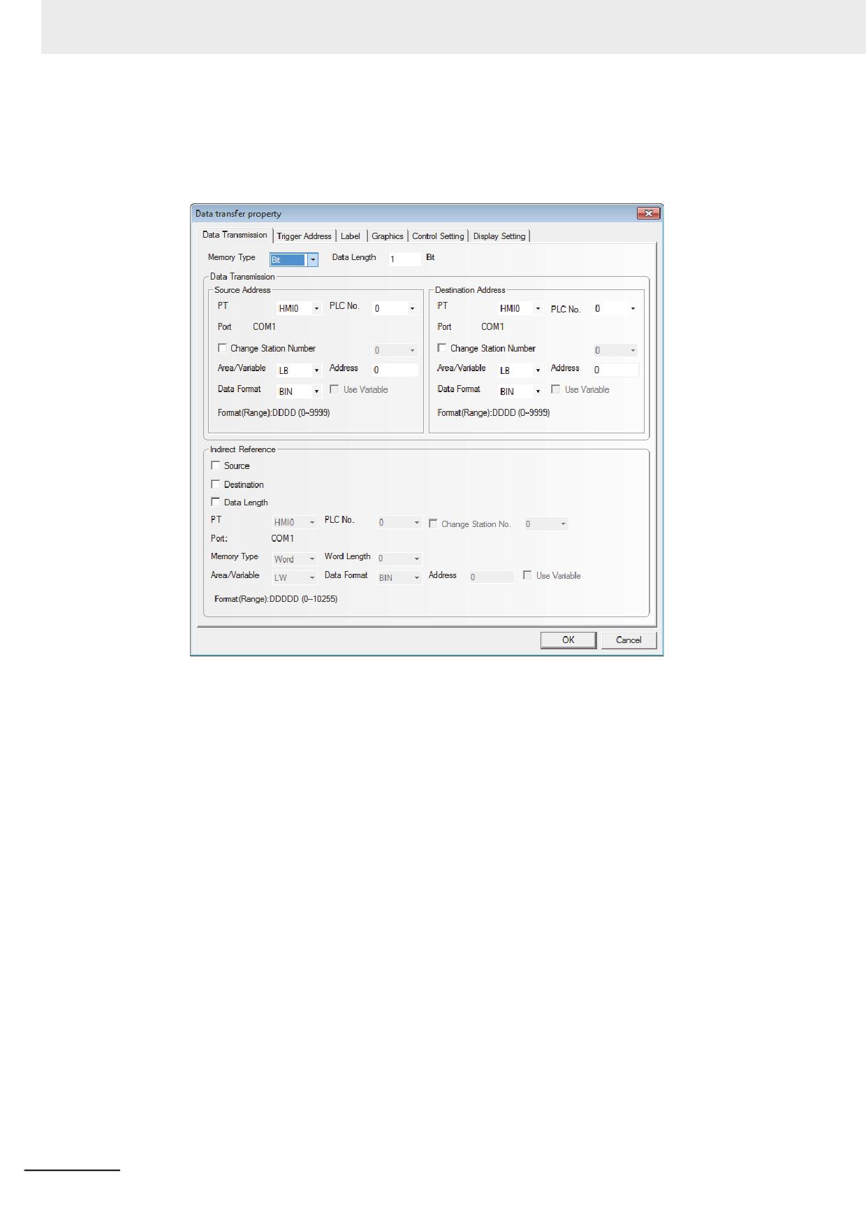
Drag the Data Transmission icon to the screen after it being pressed, then the [Data
Transmission Property] dialog box will pop up.
Memory Type: The Memory Type which is transmitted should be selected among [Bit] (bit
data) or [Word] (word data).
Data Length: The number of data transferred by the Data Transmission component. When the
Memory Type is Bit or Word, the units are “bit” or “word” respectively. A
maximum 2000 partitions of data can be specified.
Source Address: Sets the source address of the transferred data.
Destination Address: Sets the destination address of the data transmission.
Indirect Reference: Set this parameter when setting indirectly the source address, destination
address, and data length.
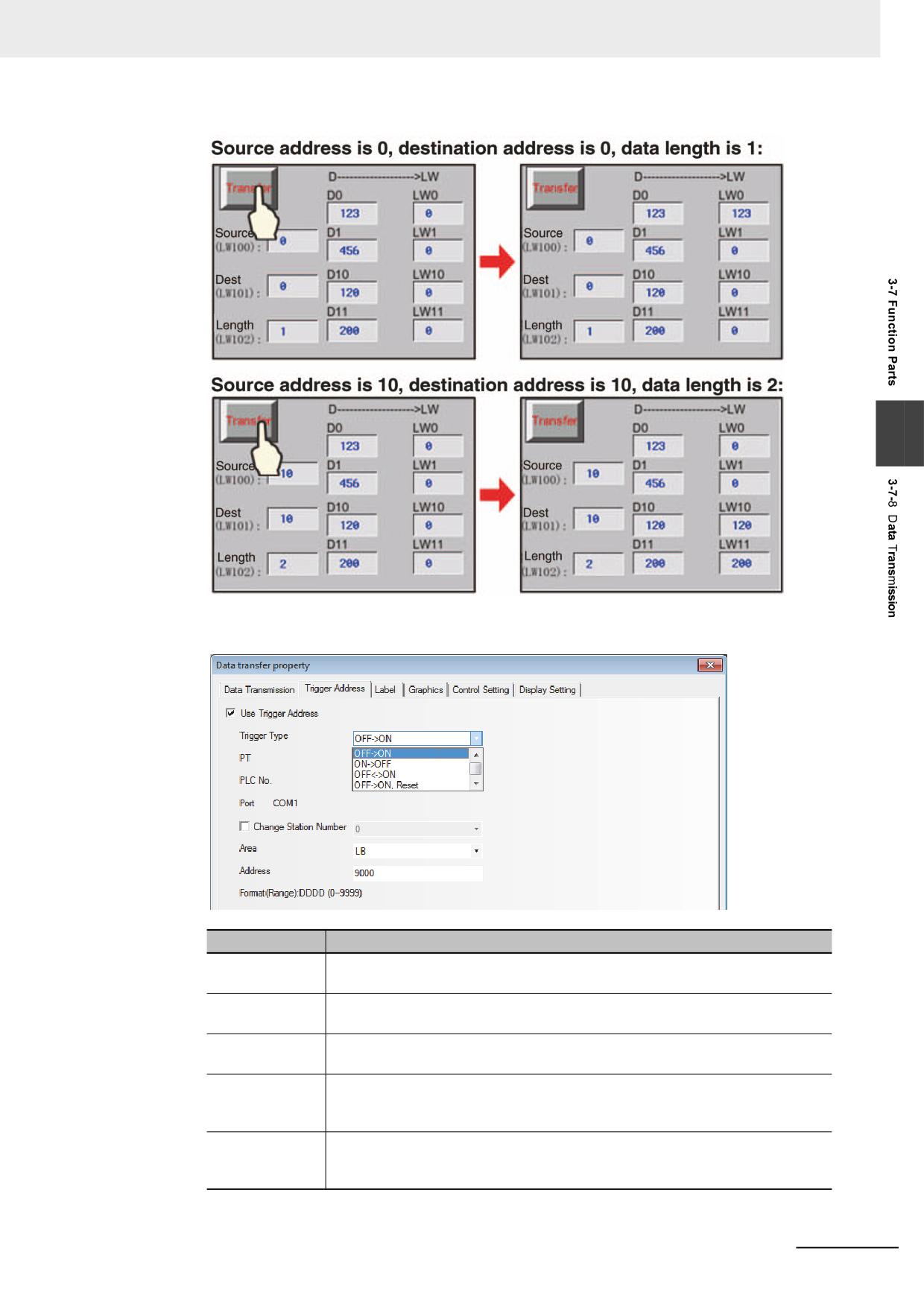
Take the following settings as example, i.e. the source address, destination address and data
length use the Indirect Reference.
After setting the source address type to “D memory” and making the source address offset
controlled by the LW100, set the destination address type to “LW memory” and make the
destination address offset and the data length controlled by the LW101 and LW102
respectively.
3-224
NB-series Programmable Terminals NB-Designer Operation Manual(V106)
3 Functions of NB-Designer
3
2
Set the [Trigger Address].
Trigger Type
Descriptions
OFFON
When the state of the specified address is switched from OFF to ON, the Data
Transmission component will be triggered to perform the transmission.
ONOFF
When the state of the specified address is switched from ON to OFF, the Data
Transmission component will be triggered to perform the transmission.
OFFON
When the state of the specified address is changed, the Data Transmission
component will be triggered to perform the transmission.
OFFON, Reset
When the state of the specified address is switched from OFF to ON, the Data
Transmission component will be triggered to perform the transmission. At the
same time with the transmission, the specified address will be turned OFF.
ONOFF, Reset
When the state of the specified address is switched from ON to OFF, the Data
Transmission component will be triggered to perform the transmission. At the
same time with the transmission, the specified address will be turned ON.
NB-series Programmable Terminals NB-Designer Operation Manual(V106)
3-225
3 Functions of NB-Designer
3
Make settings in the [Label], [Graphics] and [Control Setting] tabs by using the similar method
for the components mentioned above.
4
Press the [OK] button to complete the setup, and adjust the position and size of the Data
Transmission component.
3-7-9
Freeplotting
The Freeplotting component is based on the data in the memory, and you can use it to
draw the corresponding graphics by the pixel point in the PT.
Freeplotting Component Property
1
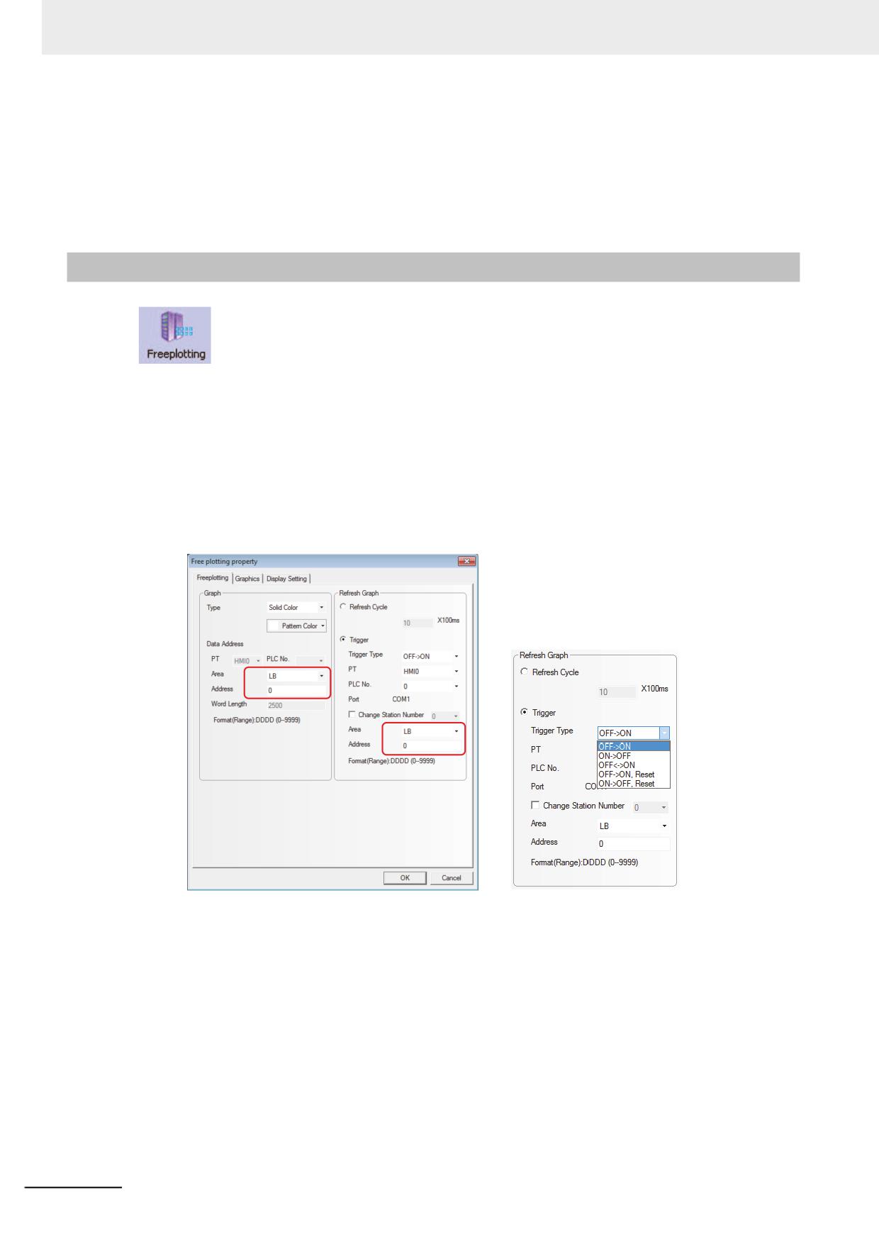
When selecting [Solid Color] for the Type (drawing graphics using the bit memory)
Set the component size to 50×50, the memory address to LB0, the pattern color to red and the
values of 2500 memories (i.e. LB0 to LB2499) to be read by PT. Then when the memory value
is 1, the pixel point of the component corresponding to the communication address which
stored the values will be applied by red color.
3-226
NB-series Programmable Terminals NB-Designer Operation Manual(V106)
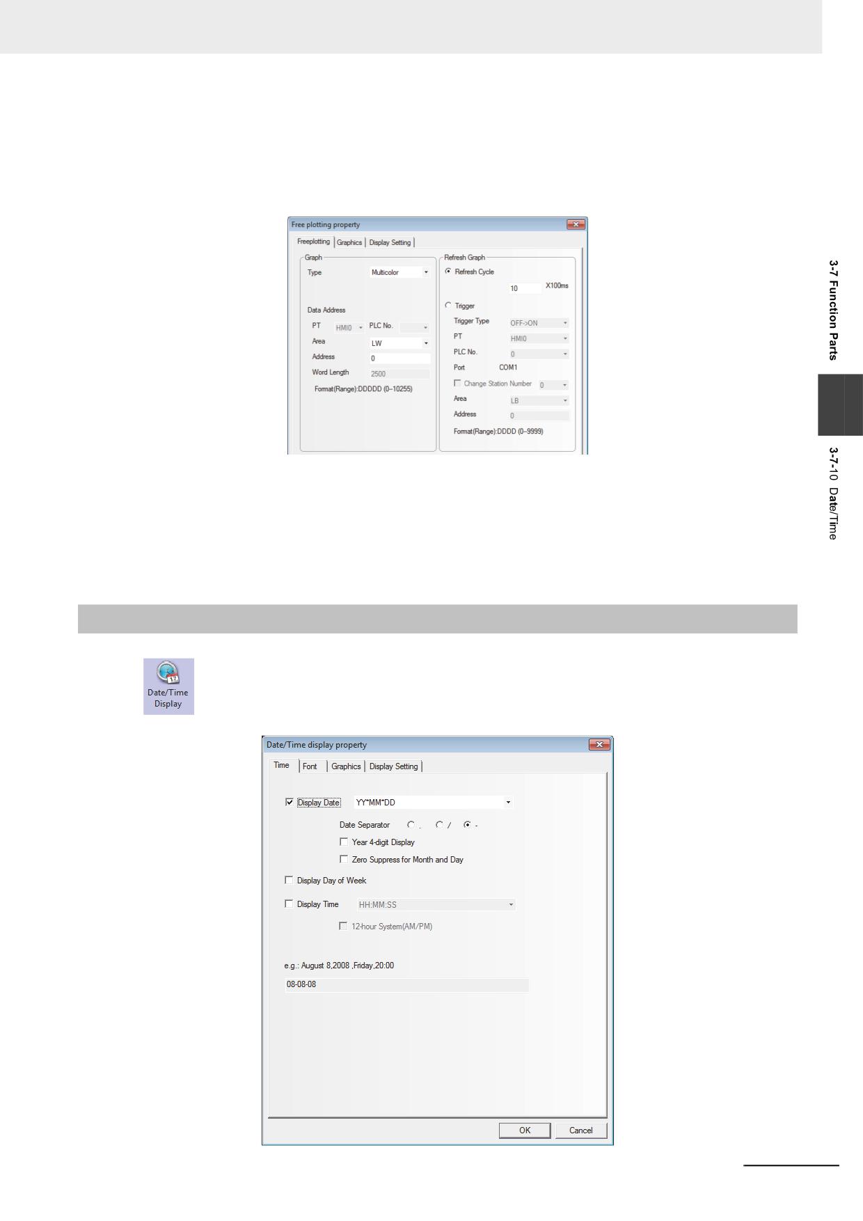
3 Functions of NB-Designer
2
Multicolor is selected for Type (Draw graphics using word memory.).
Set the component size to 50×50, the memory address to LW0, and the values of 2500 memories
(i.e. LW0 to LW2499) to be read by PT. Then the pixel point of the component corresponding to the
communication address which stored the values will be drawn into the corresponding 65536 true
color according to the actual value read from the memory.
3
3
There are two refreshing methods for the components.
Refresh Cycle: The graphics are updated at a certain period. The minimum unit to update the
graphics can be set at 100ms.
Trigger: When the status of the bit address specified with [Trigger] matches to the condition
specified with [Trigger Type], the graphics are updated.
3-7-10
Date/Time
The Date/Time component can display the value of the internal RTC clock of the PT in the set
format.
NB-series Programmable Terminals NB-Designer Operation Manual(V106)
3-227
3 Functions of NB-Designer
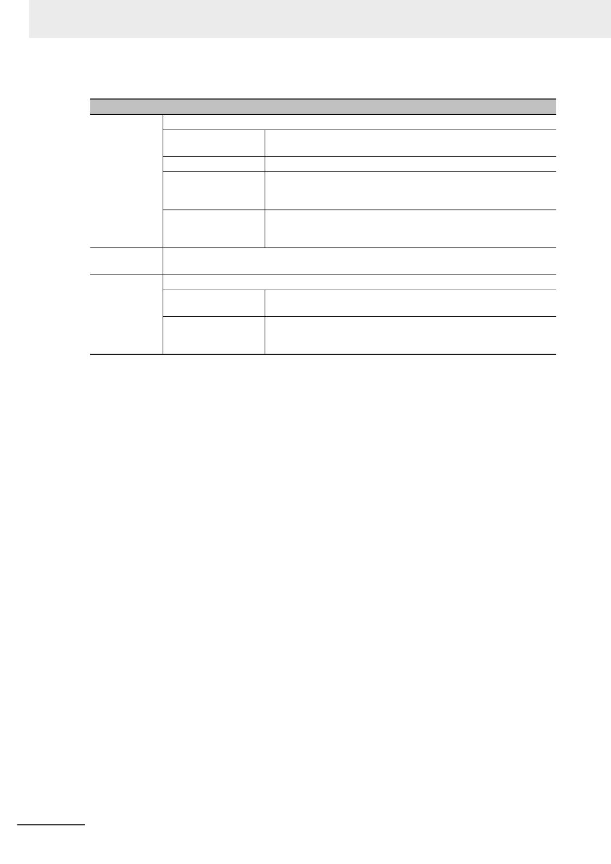
Date/Time Component Property
Descriptions of Date/Time Component Property
Display Date
Sets whether to display the date or not.
Date Format
There are four formats available, where DD, MM and YY refer to the
date, month and year respectively.
Date Separator
Three formats are available. (e.g. 2011.06.24)
Year 4-digit Display
Displays 4-digit included in the year after this option being selected.
For example: “2011 Year” will be displayed as “2011” or “11” after this
option is checked or not checked respectively.
Zero Suppress for
Clears zero included in the date and month after this option being
Month and Day
selected. For example: “June” will be displayed as “6” or “06” after this
option is checked or not checked respectively.
Display Day of
Sets whether to display the week or not.
Week
Display Time
Sets whether to display the time or not.
Time Format
There are 2 formats available, where HH, MM and SS refer to the
hour, minute and second respectively.
12-hour
The time will be displayed in 12-hour format after this option is
System(AM/PM)
checked. For example: “3 PM” will be displayed as “3:00 PM” or
“15:00” when this option is checked or not checked respectively.
The Date/Time component can only read the time of the internal RTC of the PT, but not modify the time.
If the time of the internal RTC of the PT needs to be modified, you can calibrate the system time by
using the system setup screen of the PT or modifying the values of system special memories LW10000
to LW10006.
3-228
NB-series Programmable Terminals NB-Designer Operation Manual(V106)
3 Functions of NB-Designer
3-7-11
Indirect Shape
The Indirect Shape component can modify the positions and sizes of the rectangle, ellipse or
line by changing the value of the memory.
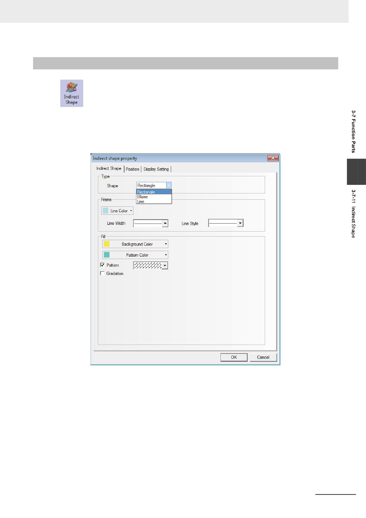
Indirect Shape Properties
1
Indirect Shape tab
3
Type: Sets the shape type from the available types of the Rectangle, Ellipse and Line.
Frame/Line: Sets the Line Color, Line Width and Line Style for the rectangle and ellipse, and
line.
Fill: Sets the fill color and the fill style for the rectangle and ellipse.
NB-series Programmable Terminals NB-Designer Operation Manual(V106)
3-229
3 Functions of NB-Designer
2
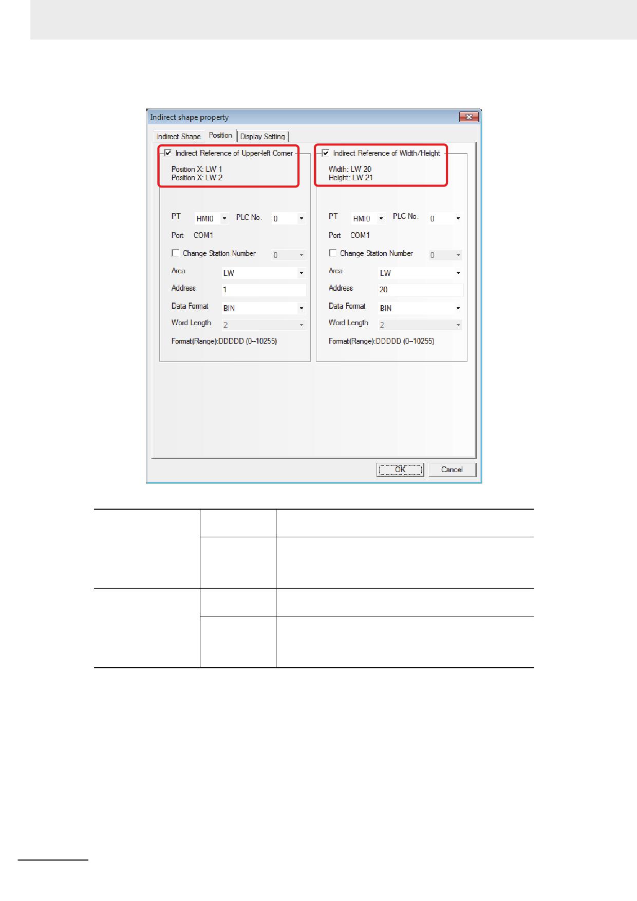
Position
The descriptions of the specific Properties are as follows:
Indirect Reference of
Unchecked
Position X and Position Y of the Indirect Shapeics are the
Upper-left Corner
constants.
Checked
Position X and Position Y of the Indirect Shapeics are the
indirect reference.
Position X = First address of the set memory,
Position Y = First address of the set memory + 1
Indirect Reference of
Unchecked
The Width and Height of the Indirect Shapeics are the
Width/Hight
constants.
Checked
The Width and Height of the Indirect Shapeics are the
indirect reference.
Width = First address of the set memory,
Height = First address of the set memory + 1
3-230
NB-series Programmable Terminals NB-Designer Operation Manual(V106)
3 Functions of NB-Designer
Example of creating Indirect Shape
1
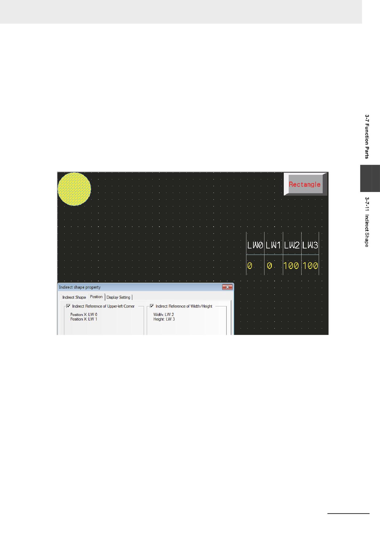
Set and place Indirect Shape (ellipse) components as follows:
• [Shape] : Ellipse
• top address of [Indirect Reference of Upper-left Corner] : LW0
• top address of [Indirect Reference of Width/Height] : LW2
Storing the values as follows, the effect is shown as below:
• LW0 (Coordinate position of X in upper-left corner) : 0
• LW1 (Coordinate position of Y in upper-left corner) : 0
• LW2 (Width) : 100
• LW3 (Height) :100
3
NB-series Programmable Terminals NB-Designer Operation Manual(V106)
3-231
3 Functions of NB-Designer
2
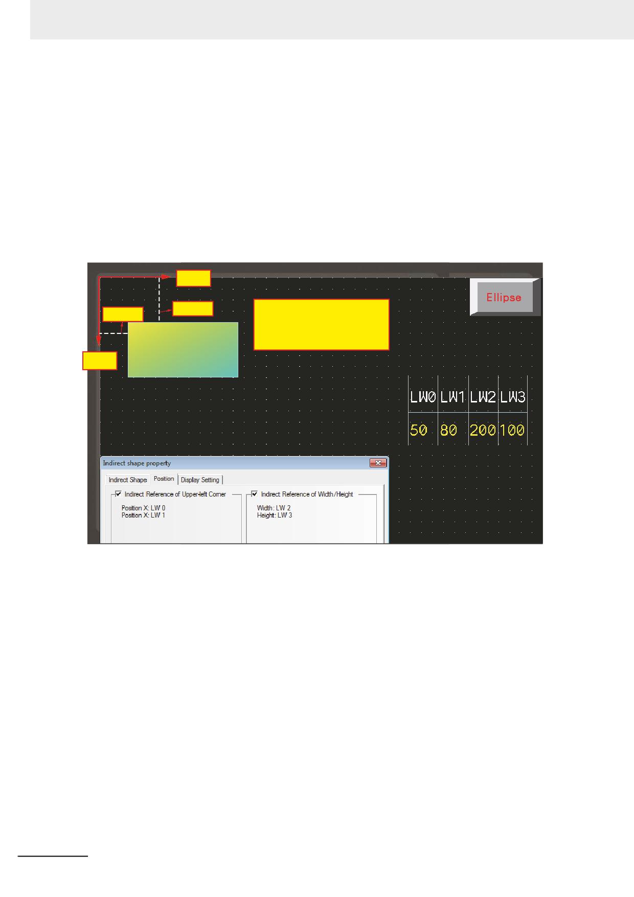
Set and place Indirect Shape (Rectangle) components as follows:
• [Shape] : Rectangle
• top address of [Indirect Reference of Upper-left Corner] : LW0
• top address of [Indirect Reference of Width/Height] : LW2
Storing the values as follows, the effect is shown as below:
• LW0 (Coordinate position of X in upper-left corner) : 50
• LW1 (Coordinate position of Y in upper-left corner) : 80
• LW2 (Width) : 200
• LW3 (Height) :100
X-axis
Screen cartesian system:
80 pixels
50 pixels
Origin in the upper left corner.
X-axis growth to the right.
Y-axis growth to the down.
Y-axis
3-232
NB-series Programmable Terminals NB-Designer Operation Manual(V106)
3 Functions of NB-Designer
3-7-12
User Information
When the system uses User Permission function, the related information of the current login
user can be displayed in the table form by using the User Information component. The User Information
component must be used in combination with the User Permission, otherwise it will not work. Refer to
3-10-6 User Permission Setting (Page 3-307) for the details.
3-7-13
Multifunction
3
The component which is unified the Bit Button and the Word Switch can operate the both the
bit set and the word set through one key.
The Multifunction component can be created by using the mouse to click [Components] -
[Button/Switch] - [Multifunction] or dragging [Multifunction] component from [Project Library Window] -
[Function Parts] to the Edit Window. The number of Actions which can be set by the Multifunction is 16
at max.
Process of adding Multifunction component
Right-click the mouse in the blank box located in the left side of Basic Properties tab in the
Multifunction Property screen to add the Bit Set or Word Set in the procedure as follows.
1
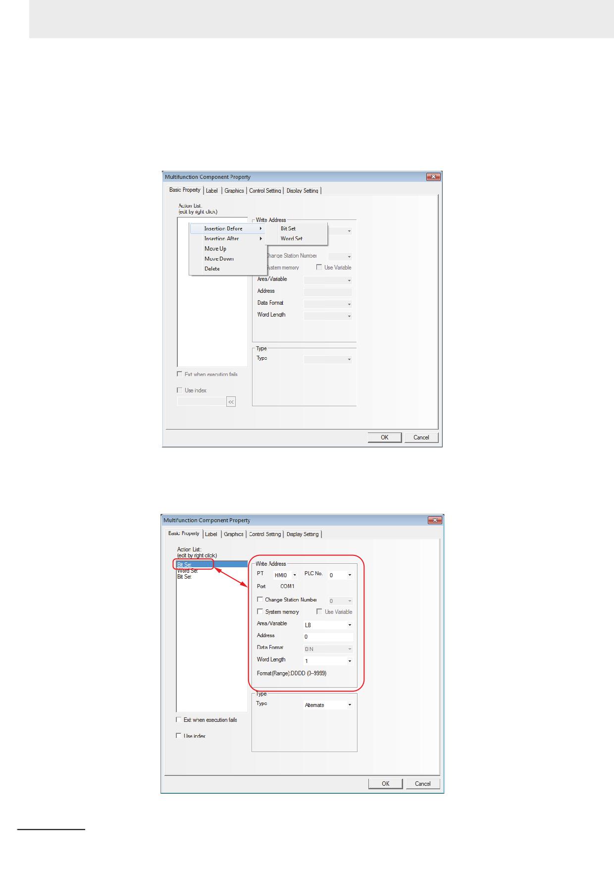
Add the actions (Bit Set and Word Set). Right-click the Action List to select [Insertion Before] or
[Insertion After] option to change the execution order of the component.
NB-series Programmable Terminals NB-Designer Operation Manual(V106)
3-233
3 Functions of NB-Designer
2
According to the order to be executed, change the position of the action which was added.
Right-click the Action List to select [Move Up] or [Move Down] option to change the execution
order of the component.
3
In order to delete the action which was added, right-click the Action List to select [Delete]
option to delete this component.
4
Edit the Property of the Action.
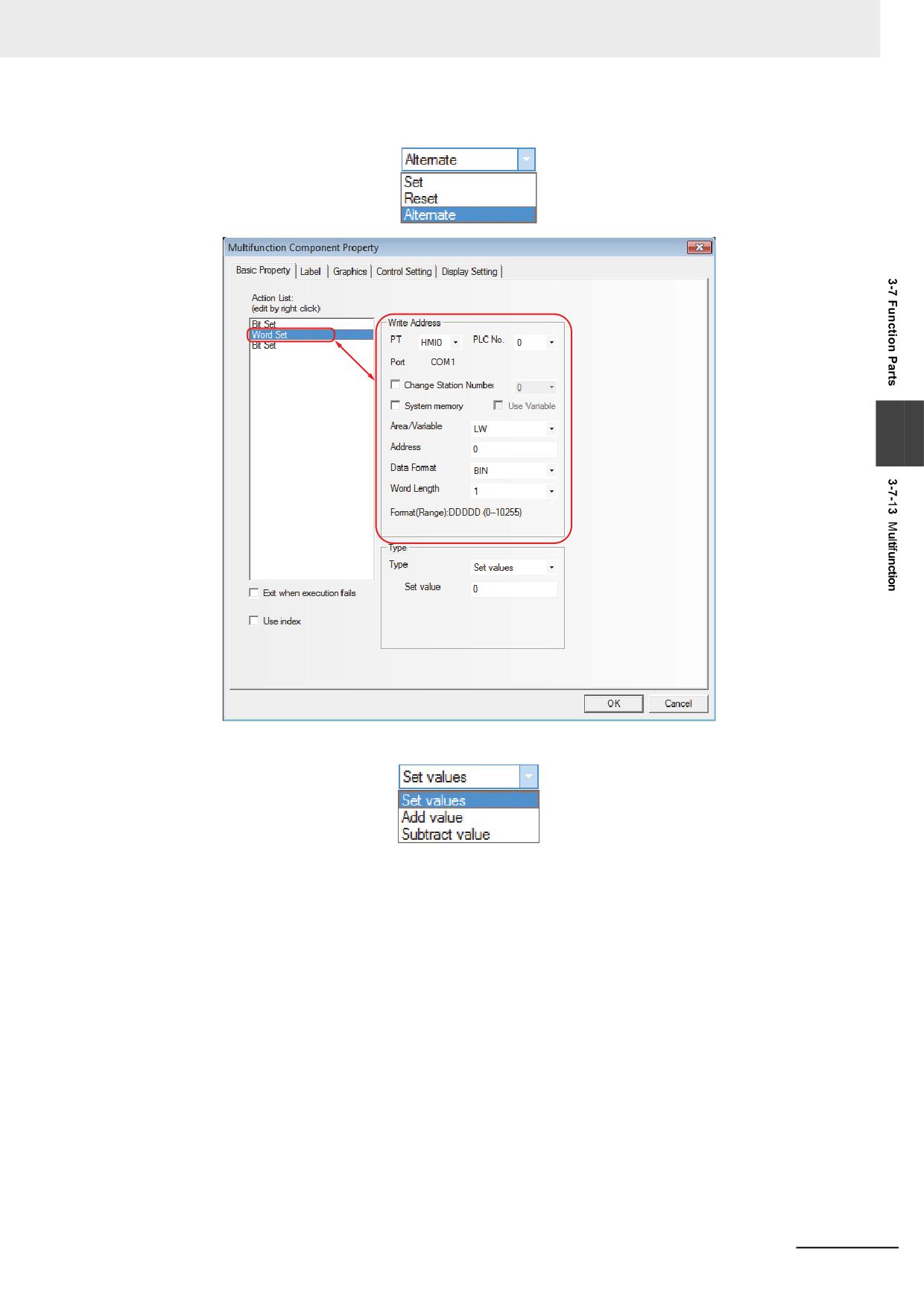
The Property of the Action which was added (Bit Set and Word Set) can be set for each Action
at the right area in the [Basic Properties] tab.
3-234
NB-series Programmable Terminals NB-Designer Operation Manual(V106)
3 Functions of NB-Designer
The Bit Set support the Types of [Set], [Reset], and [Alternate] only.
3
The Word Set support the Types of [Value Setting], [Add Value], and [Subtraction Value] only.
5
If the function specified according to the Action List order (ascending order) is failed to execute
normally, set the executing operations of the Multifunction by the [Exit when execution fails]
checking box.
• Checking the check box
When executing the function in the order of the Action List, if the specified function cannot be
executed, the execution of the Multifunction is quit at the moment and the Action on the List
is not executed.
• Unchecking the check box
Even if the specified function cannot be executed, when executing the function in the order
of the Action List, the next Action on the List will be executed.
NB-series Programmable Terminals NB-Designer Operation Manual(V106)
3-235
3 Functions of NB-Designer
3-7-14
Event Display
Event Display is used to make the event information logged in [Event Setting] database
and meeting the current triggering conditions displayed scrolling from the right to the left.
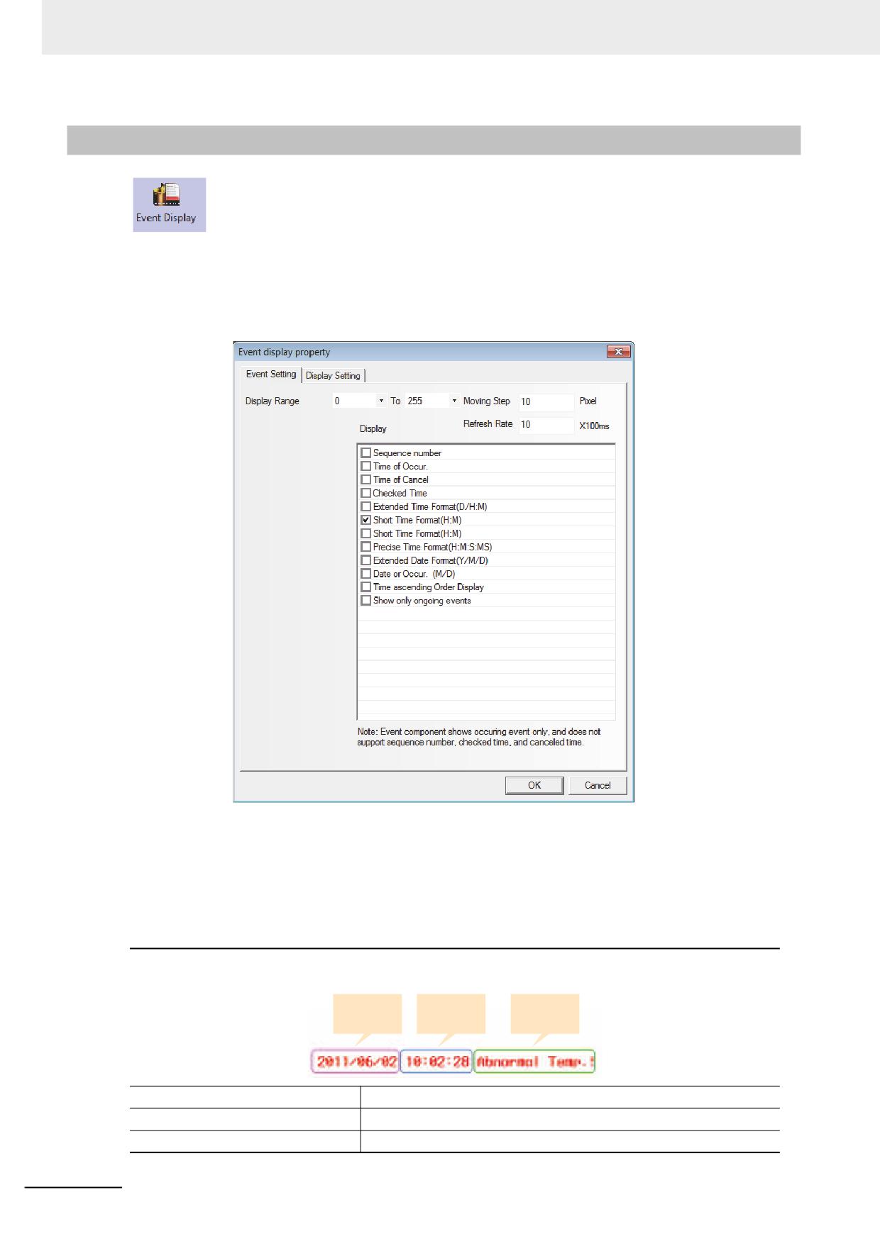
Event Display Property
1
Event Setting tab
Display Range: Specify the range of displaying types (formats) of the event.
Moving Step: The pixel point of the width to display the event information in loopy way in units
of pixel.
Refresh Rate: The period to refresh the display of the event information in loopy way in units
of 100ms.
Display: The contents are as follows.
For the displayed format of event information, all the selected format information will be displayed before the
event information.
Date of
Time of
Event
Occur.
Occur.
content
Time of Occur.
The time when the event is triggered.
Extended Time Format (D/H: M)
The time format is displayed as Day/Hour: Minute.
Short Time Format (H: M)
The time format is displayed as Hour: Minute.
3-236
NB-series Programmable Terminals NB-Designer Operation Manual(V106)
3 Functions of NB-Designer
Standard Time Format (H: M: S)
The time format is displayed as Hour: Minute: Second.
Precise Time Format (H: M: S: MS)
The time format is displayed as Hour: Minute: Second: Millisecond.
Extended Date Format (Y/M/D)
The date is displayed as Year/Month/Day.
Date of Occur. (M/D)
The date is displayed as Month/Day.
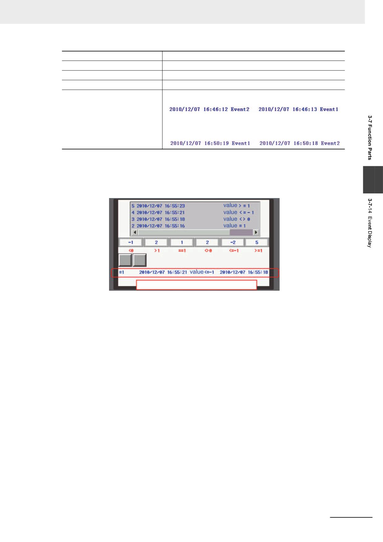
Time ascending Order Display
Checking this option means the event time ascends from the front to
back with the latest event information at the end, as shown below:
Not-checking this option means the event time descends from the
front to back with the latest event information at the front, as shown
below:
Note 1
The Event Display only displays the occurring event, and dose not support “Sequence No.”, “Time of Can-
cel” and “Check Time”.
2
Once the triggered event information is unmatched, the unmatched event will not be displayed in the
Event Display anymore.
3
The effect of offline test is as shown below.
Current trigger event is displayed in the Event Display.
NB-series Programmable Terminals NB-Designer Operation Manual(V106)
3-237
3 Functions of NB-Designer
3-8
Project Database
3-8-1
Text Library
Text Library can be used to store the text contents needed by the project, thus preventing
the label with the same text from being input frequently. In addition, Text Library can be used to the
conditions with the requirement of multi-language support to realize the switching among the multiple
languages for the PT Edit screen. NB-Designer currently supports up to 32 kinds of languages setting.
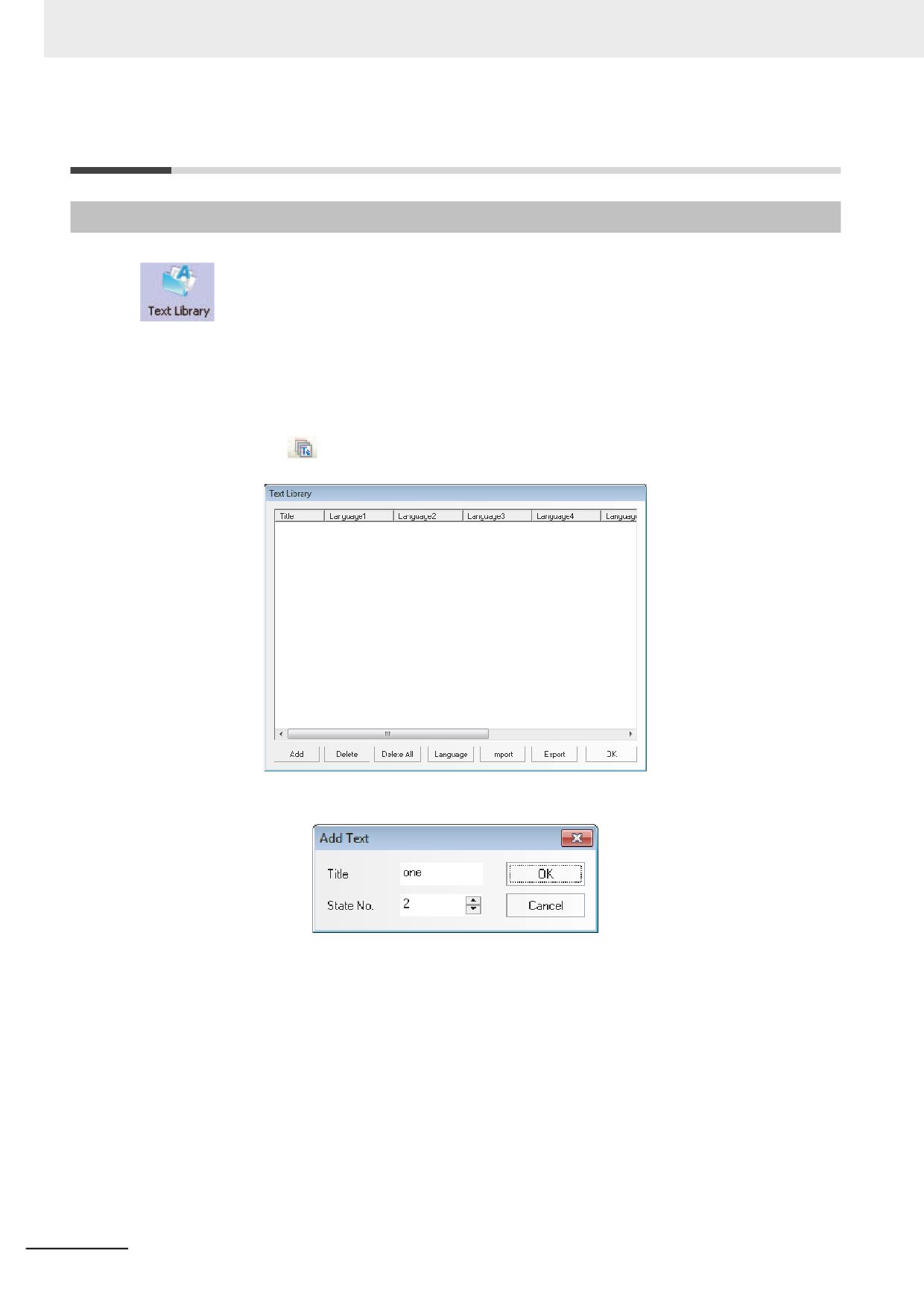
1
Text Input
(1) Pressing
icon or clicking [Text Library] in the [Project Database] of the [Project
Library] allows the Text Library to pop up.
(2) When the following “Add Text” dialog box appears after “Add” being clicked, fill in the Title,
State No. and click “OK” to proceed to the next step.
Note Once the text title is registered, it cannot be modified in the [Text Library] dialog box.
3-238
NB-series Programmable Terminals NB-Designer Operation Manual(V106)
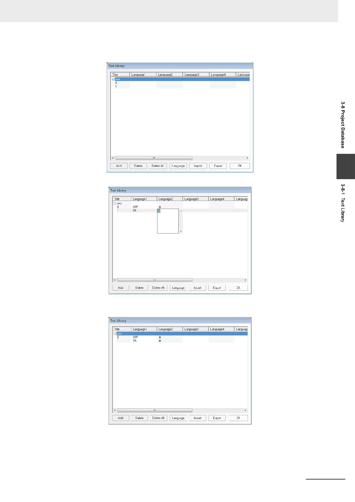
3 Functions of NB-Designer
(3) The text added just now has been in the Text Library already, and click the “+” placed
before the “Title” to see the text string.
3
(4) Input the text in each language for each state, as shown below.
(5) If you use 2 states, it just needs to input the corresponding text to state 0 and state 1
respectively for each language, and then click “OK” after the completion of the text addition.
NB-series Programmable Terminals NB-Designer Operation Manual(V106)
3-239
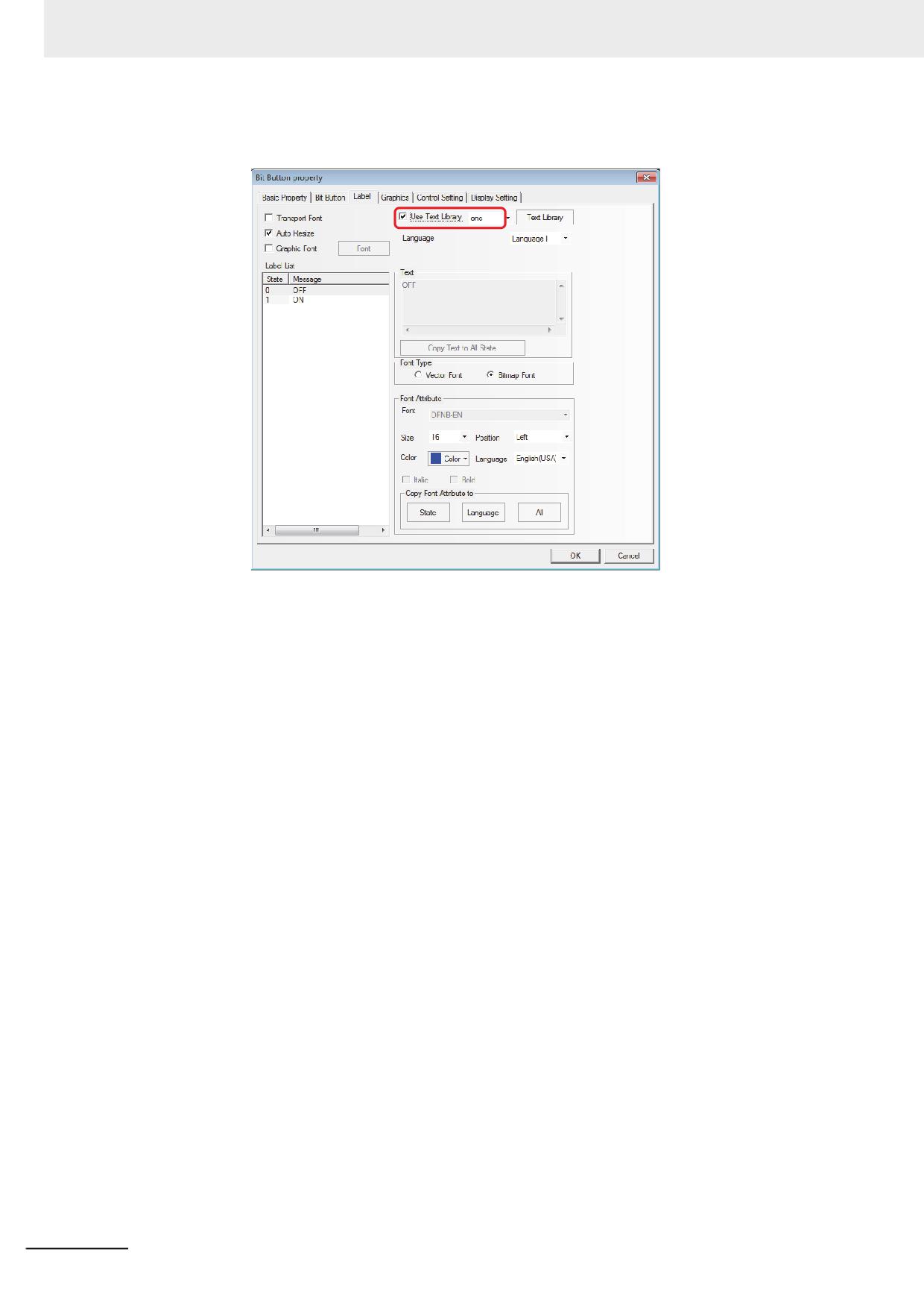
3 Functions of NB-Designer
(6) Checking the [Use Text Library] check box in the [Label] tab of dialog box for each Property
allows using the text string which was registered to the [Text Library].
If you haven’t added the text to the Text Library, “Use Text Library” can’t be checked and is
always grayed out until you have added the text into the Text Library.
2
Multi-language Switching
The switching among the multiple languages can be realized by modifying the value of special
register system memory (LW9130). As long as the value of LW9130 is changed in any one of
screens, the displayed text will switch to the text (language) corresponding to the value being
changed to, and the language of the whole system will be changed regardless of the condition
of the current screen. Only resetting the value of LW9130 can make the language switched
again.
It is based on the system special memory LW9130 to realize the multi-language switching in
the Text Library.
That’s to say:
When LW9130 is 0, the contents corresponding to Language 1 in Text Library will be displayed;
When LW9130 is 1, the contents corresponding to Language 2 in Text Library will be displayed;
When LW9130 is 2, the contents corresponding to Language 3 in Text Library will be displayed;
and so on.
When LW9130 is 31, the contents corresponding to Language 32 in Text Library will be
displayed;
When LW9130 is greater than 31, the contents corresponding to Language 1 in Text Library will
be displayed.
Note
“Number of Language” in [PT Property]-[PT Extended Properties] can restrict the number of Language(s)
displayed in Text Library. When the Text Library is used for the first time, the default “Number of
Language” is 8. Even if LW9130 is greater than 8, the system can only display the contents corresponding
to Language 1 to Language 8. If the languages to be displayed are greater than 8 [Max No. of Languages]
needs to be increased in [Language Setting] screen with [Number of Language] not exceeding [Max No.
of Languages].
“Default Language” in [PT Property]-[PT Extended Properties] refers to the language number to be
displayed in the default Text Library. For example: When Language 2 in the Text Library is English, if
“Default Language” is set to “2”, the text using the Text Library will be displayed as “English” on the
System Screen after PT is powered ON and be switched to another language until the value of LW9130 is
changed.
3-240
NB-series Programmable Terminals NB-Designer Operation Manual(V106)
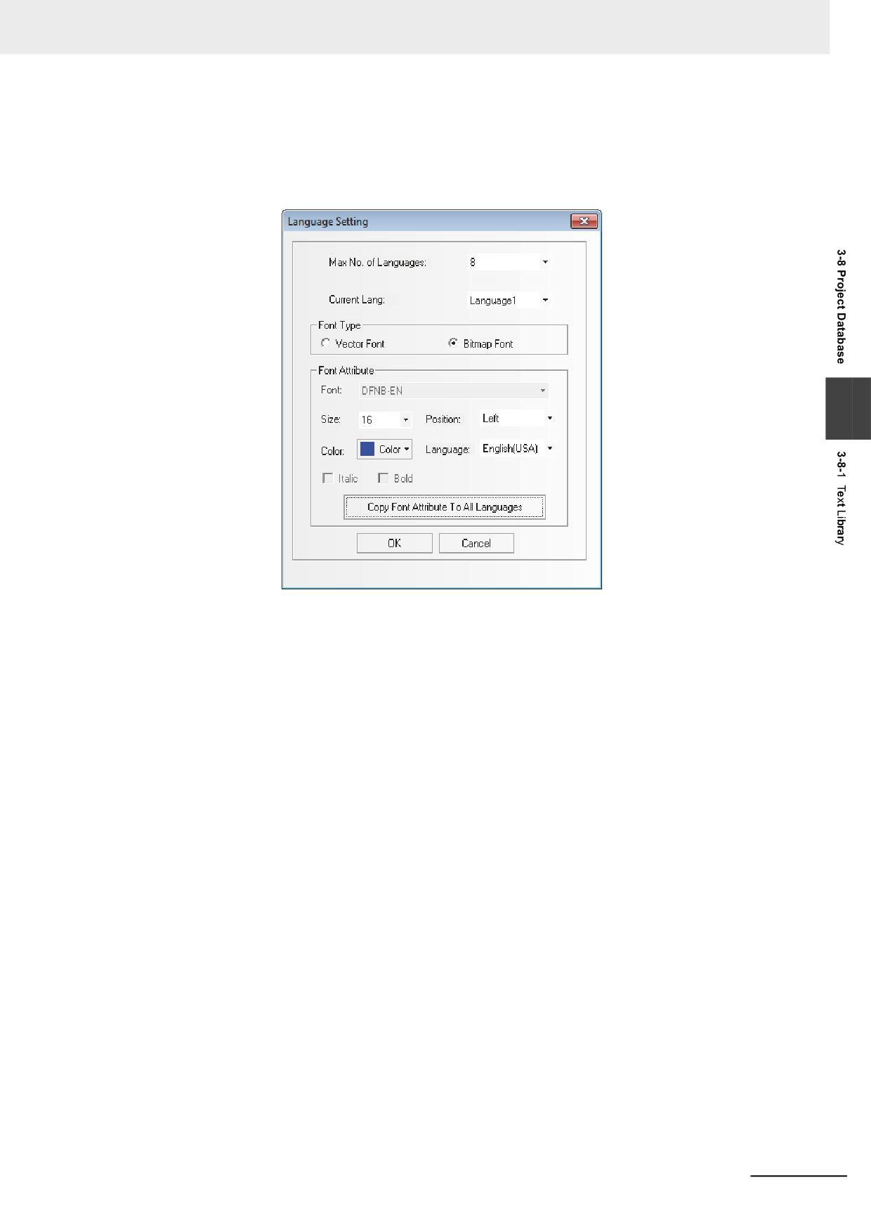
3 Functions of NB-Designer
3
Language Setting of Text Library
Clicking “Language Setting” in [PT Property]-[PT Extended Properties] or clicking “Language”
from the Text Library can open [Language Setting] dialog box to set the global Property of the
text font corresponding to each kind of language.
3
Max No. of Languages: The Text Library supports up to 32 kinds of languages with the
Default Language of 8. If the user needs more than 8 kinds of
languages, the Max No. of Language should be increased.
Current Lang: Refers to the language being edited currently.
Font type: Sets the font type of the language used currently to Vector Font or Bitmap Font .
Font Attribute: Sets the related attributes of the language used currently such as the Font,
Size, Position, Color and Italic and Bold.
Copy Font Attribute To All Language: Copying the font attribute which is edited currently to
all the other languages.
Language: The description of the language which is edited currently. The entry procedure to
the OS of the current PC is displayed.
Note 1
Although the font attribute for each language specified to [Language Setting] is specified to all the compo-
nent as default, the font attribute specified individually for each component attribute in the [Label] tab has
a high priority.
2
Changing the Font Attribute setting in [Language Setting] will not affect the component specified already
the Text Library as the font attributes of label. To use the Font Attribute modified in [Language Setting], it
needs to recheck “Use Text Library” in [Label] tab after the checking being cancelled, in order to refresh
the Font Attribute setting in [Language Setting].
4
Import/Export of Text Library
Text Library has the functions of importing & exporting the registered text in CSV format.
Exporting the registered text to the Text Library to the one in CSV format allows edition by the
spreadsheet software. Also importing the edited file can be taken in the NB-Designer.
NB-series Programmable Terminals NB-Designer Operation Manual(V106)
3-241
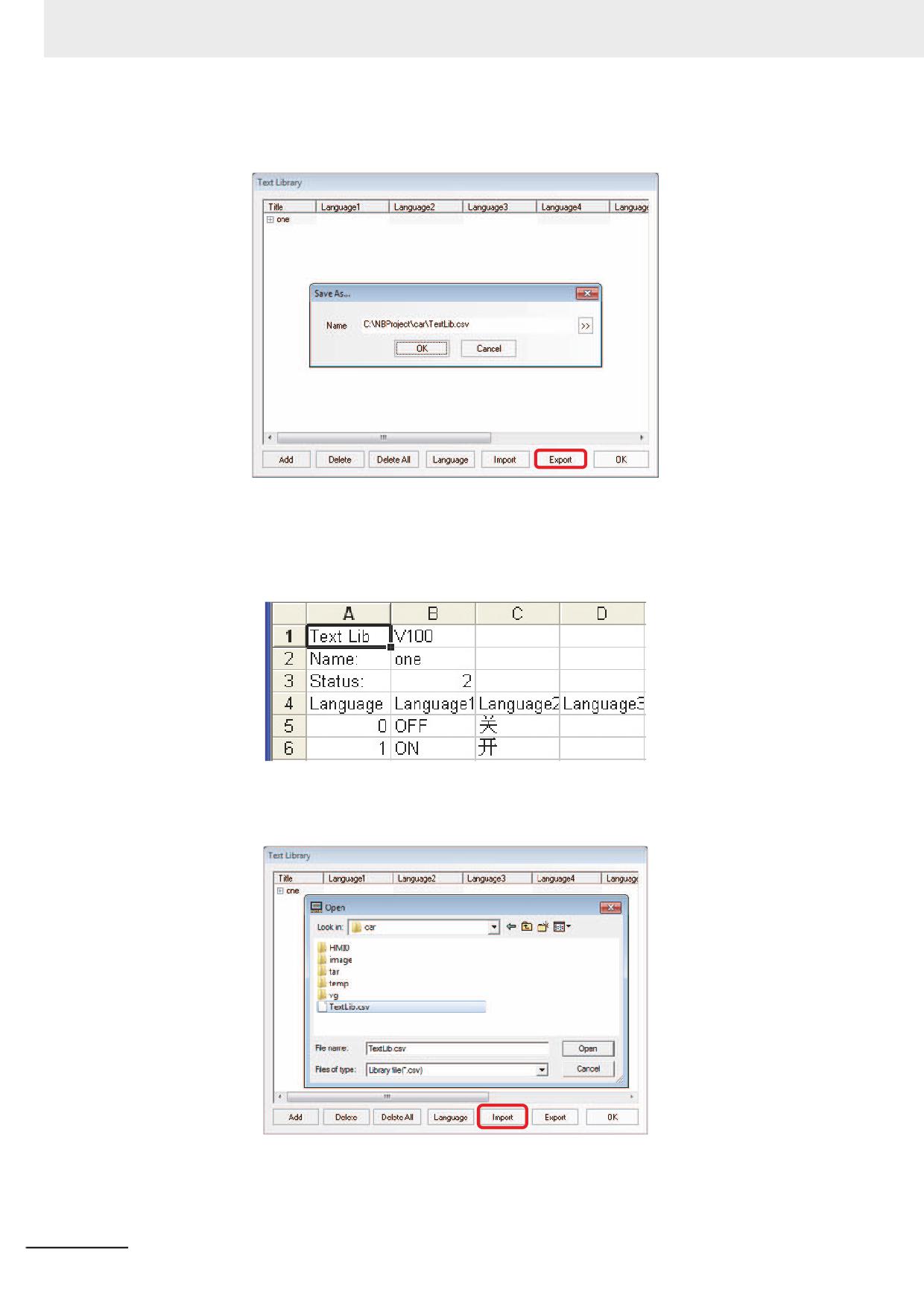
3 Functions of NB-Designer
Export Text Library
(1) The following dialog box will pop up after “Export” is clicked.
(2) Click [OK] to export the file. In order to change the destination to save the file and the
filename, click [>>] and specify the destination to save the file to and the filename.
(3) If the exporting is completed, the message saying “The file is exported successfully!” will be
pop up.
The opened export file in .csv format is as shown below.
Import Text Library
(1) The following dialog box will pop up after “Import” is clicked.
(2) After confirming the CSV file supposed to be imported is not opened by other software,
select the CSV file and click [Open].
(3) If “Import file successfully” pops up, it means the import is successful.
3-242
NB-series Programmable Terminals NB-Designer Operation Manual(V106)
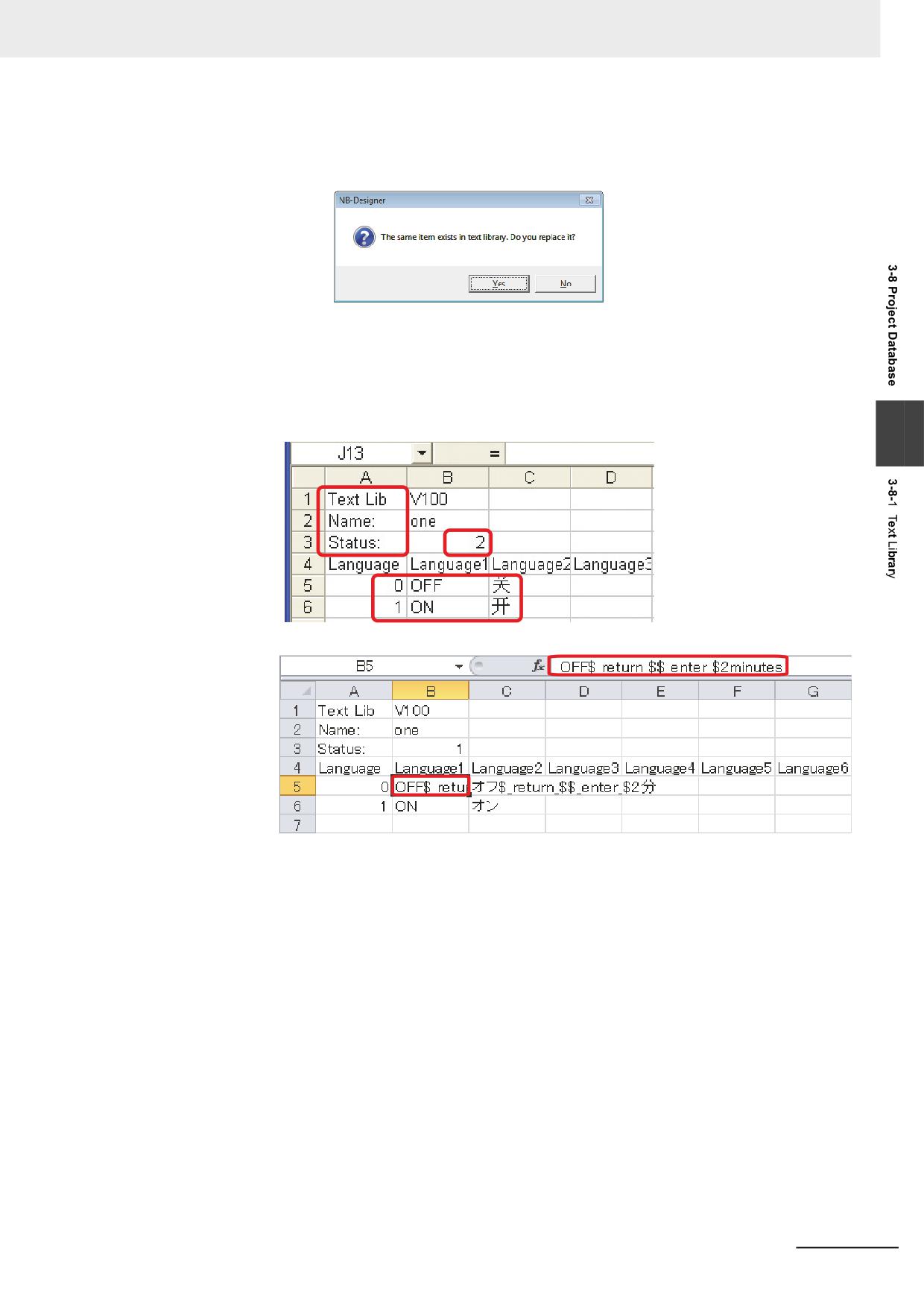
3 Functions of NB-Designer
(4) If the imported file in .csv format has the items having the same name with that in the
existing Text Library of the system, the selection dialog box will pop up.
In this case, you can select “Yes” or “No” according to the circumstances.
Notes for Import & Export
(1) The text strings such as “Text Lib”, ”Name” and “Status” included in the .csv file can’t be
changed, otherwise import will be impossible. Meanwhile, the value of “Status” must be
consistent with the actual status lines, as shown below, i.e. when “Status” is 2, the two
statuses contained in the text can only be “0” and “1”.
3
(2) If the line-break exists in the contents of Text Library, the exported file is shown as below.
If line-break is needed in spreadsheet software file, it just needs to input
“$_return_$$_enter_$”.
(3) Even after editing the CSV file by spreadsheet software, select “Unicode Text (*.txt)” for
[Type of Document] to save the file and then quit the used application and finally rename
the filename extension to .csv. The other file format cannot be recognized as available file
to import.
(4) The “Import” & “Export” are only applicable to the whole Text Library rather than the single
text item contained in the Text Library.
NB-series Programmable Terminals NB-Designer Operation Manual(V106)
3-243
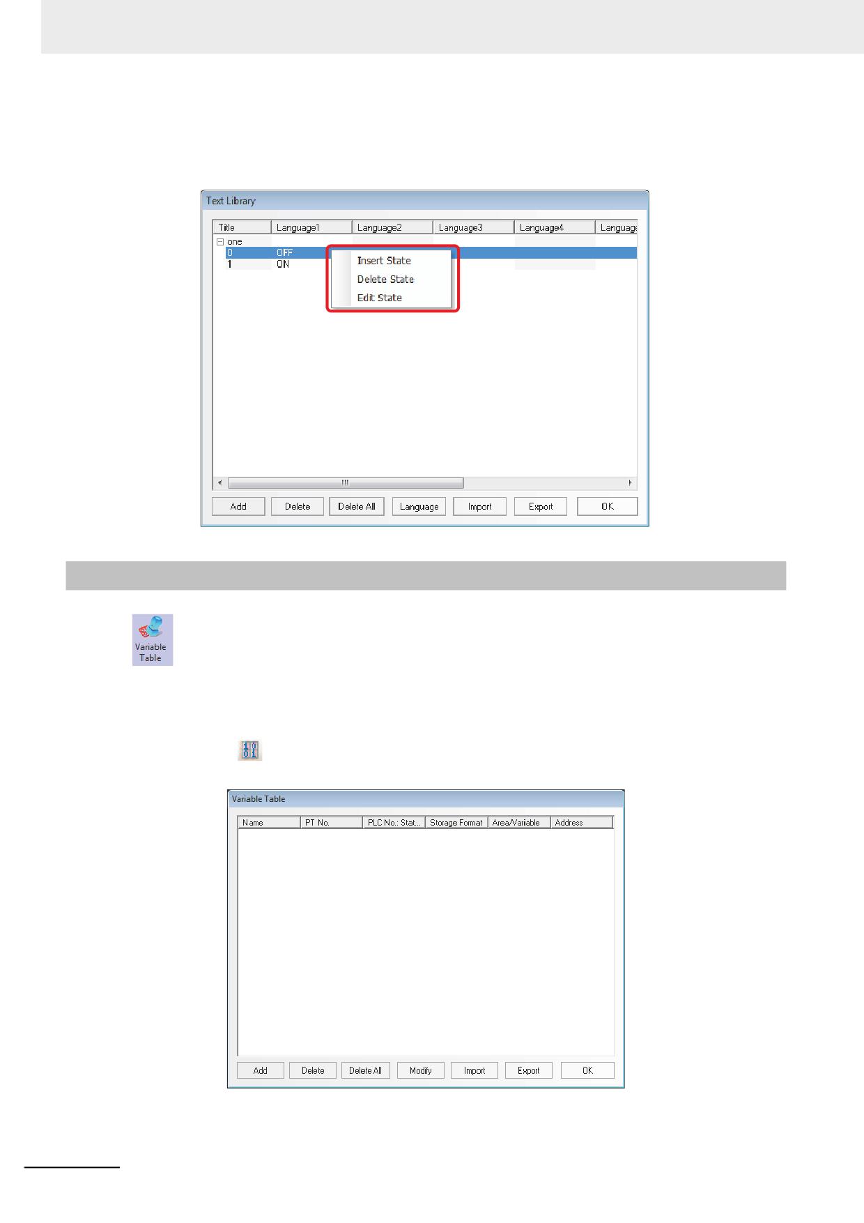
3 Functions of NB-Designer
5
Change of State Number of Text Library
The change method of states number of Text Library is to select one state and right-click the
mouse, as shown below.
3-8-2
Variable Table
Variable Table is a useful address logon library, which prevents the inconvenience resulting
from repeated input of address, thus saving a lot of time. Check the [Use Variable] check box in setting
items for each component to use the address which was registered to the Variable Table with the
settings for each component.
1
Clicking
icon or entering [Variable Table] in the [Project Database] allows Variable Table to
pop up.
3-244
NB-series Programmable Terminals NB-Designer Operation Manual(V106)
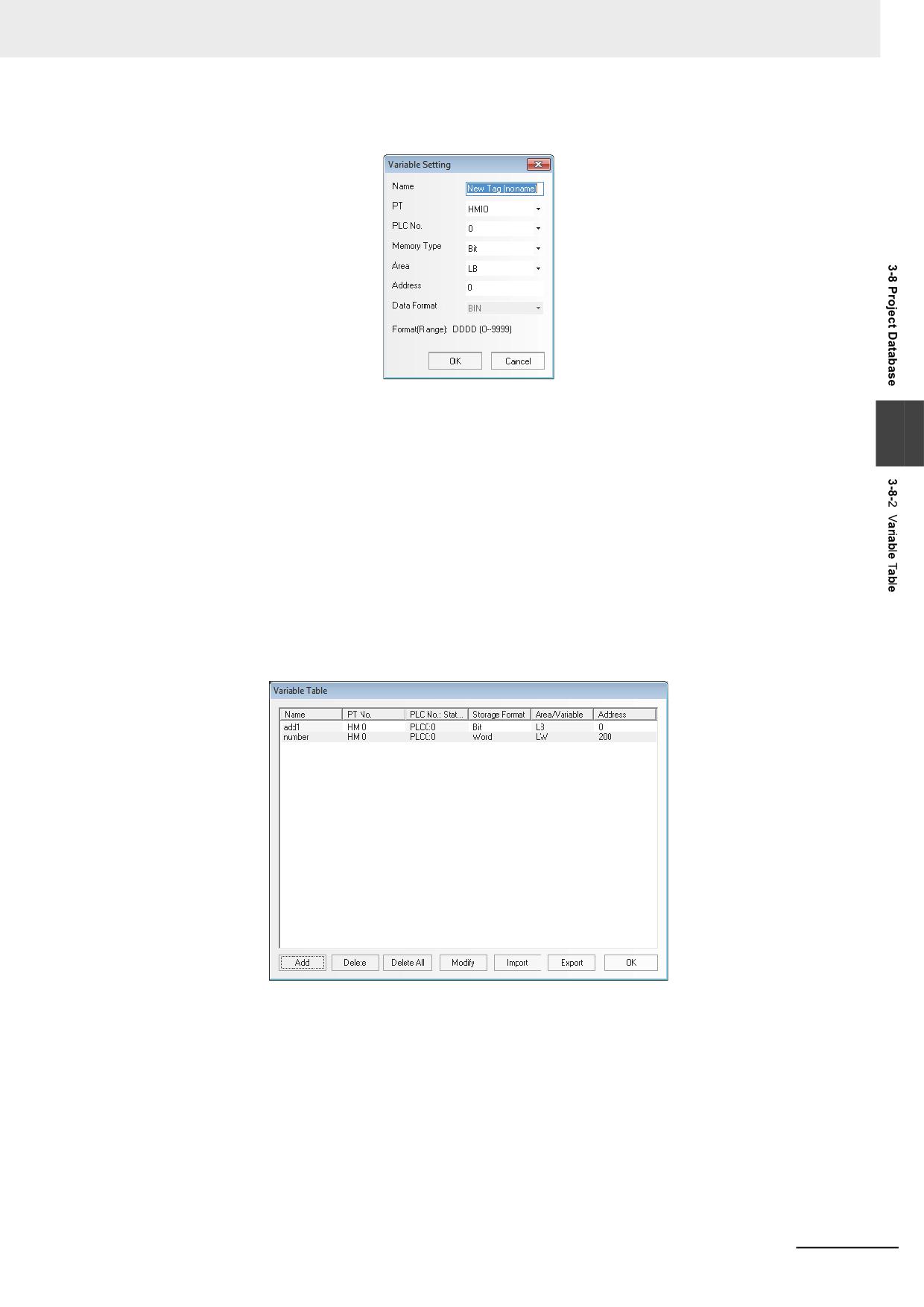
3 Functions of NB-Designer
2
Click “Add” to make the following small dialog box pop up.
Name: Inputs the name of this variable.
PT: Selects the No. of PT corresponding to this variable.
3
PLC No. : Selects the No. of PLC corresponding to this variable.
Memory Type: Selects the memory type corresponding to this address from “Bit” or “Word”.
Area: Selects the area corresponding to this variable from “the internal memory of the PT” and
“the memory of the PLC”.
Address: Specify the address corresponding to the adding address.
Data Format: Select the data format of the adding address from “BIN” or “BCD”.
Format (Range): Displays the address format (the address range) of this variable.
3
Input the above-mentioned items respectively, and click “OK”, then the variable will appear in
the library.
NB-series Programmable Terminals NB-Designer Operation Manual(V106)
3-245
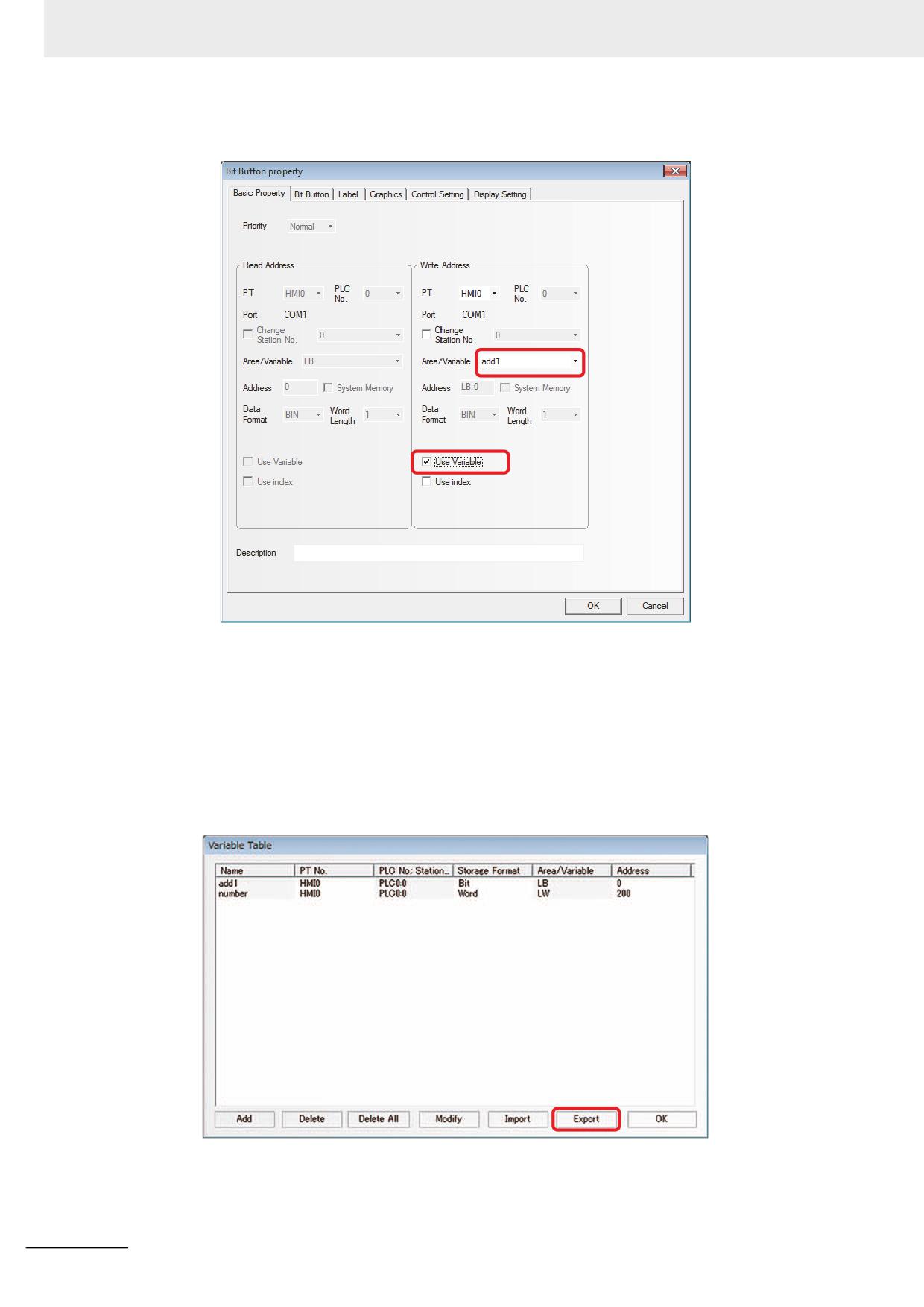
3 Functions of NB-Designer
4
Later you can use it in the other places, as shown below.
Note 1
The addresses having been logged in the Variable Table can’t be changed in the other places, that’s to
say, they can only be used. If they are needed to be changed, you just need to enter the Variable Table
dialog box to change the address.
2
Note the following points when using the Variable.
The Variable specified [Bit] for the [Memory Type] can be allocated only to the bit state component. Also
the Variable specified [Word] for the [Memory Type] can be allocated only to the word state component.
5
Importing/Exporting a Variable Table
You can save variable information as a CSV file by pressing the [Export] button.
3-246
NB-series Programmable Terminals NB-Designer Operation Manual(V106)
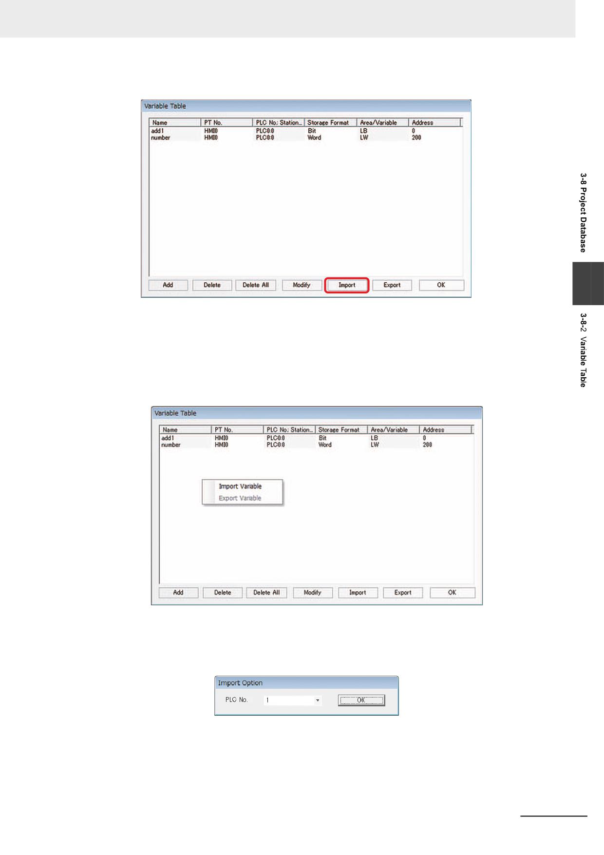
3 Functions of NB-Designer
Press [Import] to import the variable information from a CSV file.
3
6
Importing Variables of NJ and NX Series
Variables of NJ and NX series can be imported to a variable table.
(1) Click [Tools] - [Export Global Variables] - [CX-Designer] under the Sysmac Studio Menu to
export the information about variables of NJ and NX series to Clipboard.
(2) Right-click on the Variable Table window. Select [Import Variable] to load the variable
information exported to the Clipboard *1.
*1 Importing variables is allowed only when you are using Omron Host that executes Ethernet com-
munication.
(3) A window to select a host appears after importing variables. Select the host, an import
destination.
NB-series Programmable Terminals NB-Designer Operation Manual(V106)
3-247
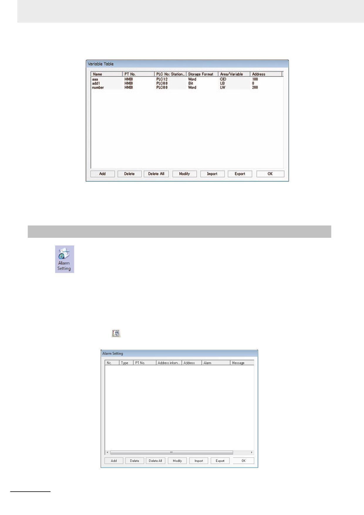
3 Functions of NB-Designer
(4) Click [OK] to import the variables of NJ and NX series.
Note You can import only variables to which AT Specification address is allocated in Sysmac Studio.
Variable types to be imported are: BOOL, UINT/ INT/ WORD, UDINT/ DINT/ DWORD/ REAL.
On NB-Designer, BOOL variable is replaced to Bit, UINT/ INT/ WORD are replaced to Word, and UDINT/
DINT/ DWORD/ REAL are replaced to DWORD.
DWORD variable cannot be edited on NB-Designer.
3-8-3
Alarm Setting
To display the information on the Alarm component or Alarm Display component, the logon in
the list of [Alarm Setting] database is needed. One bit address can control whether one piece of
information will be displayed or not. If the logged bit address is triggered (ON or OFF), the related
information will be displayed on the Alarm component. (This component is only responsible for the
logon of Alarm Setting, and the display needs to be done by “Alarm” component.)
Add/Modify Alarm Setting
1
Clicking the
icon located in the Database Toolbar or the “Alarm Setting” in the “Project
Database” allows an “Alarm Setting” dialog box to pop up.
3-248
NB-series Programmable Terminals NB-Designer Operation Manual(V106)
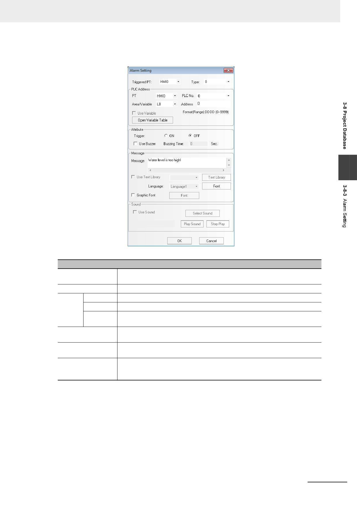
3 Functions of NB-Designer
2
Select the [Add] button to add the setting or select the [Modify] button to modify the existing
setting.
3
Descriptions of Alarm Information Property
Triggered PT
Select one PT to specify the Alarm Setting when multiple PTs were registered to the
project.
PLC Address
Specifies the bit address of the memory that triggers the read of the alarm.
Property
ON
When the specified bit address is ON, one piece of alarm information is generated.
OFF
When the specified bit address is OFF, one piece of alarm information is generated.
Use Buzzer
When the alarm information is triggered, the buzzer will be enabled. The Buzzing
Time can be set with the unit of “second”.
Message
Inputs the contents of alarm setting to be displayed. Clicking [Font] can set the Font
and the related attributes.
Use Text Library
Determines whether to use the contents logged in the Text Library. For the use of
the Library, refer to [3-8-1 Text Library].
Language
When using multi-language Text Library, you can select the language here and click
“Font” to set the font attributes corresponding to text in each kind of language
respectively.
NB-series Programmable Terminals NB-Designer Operation Manual(V106)
3-249
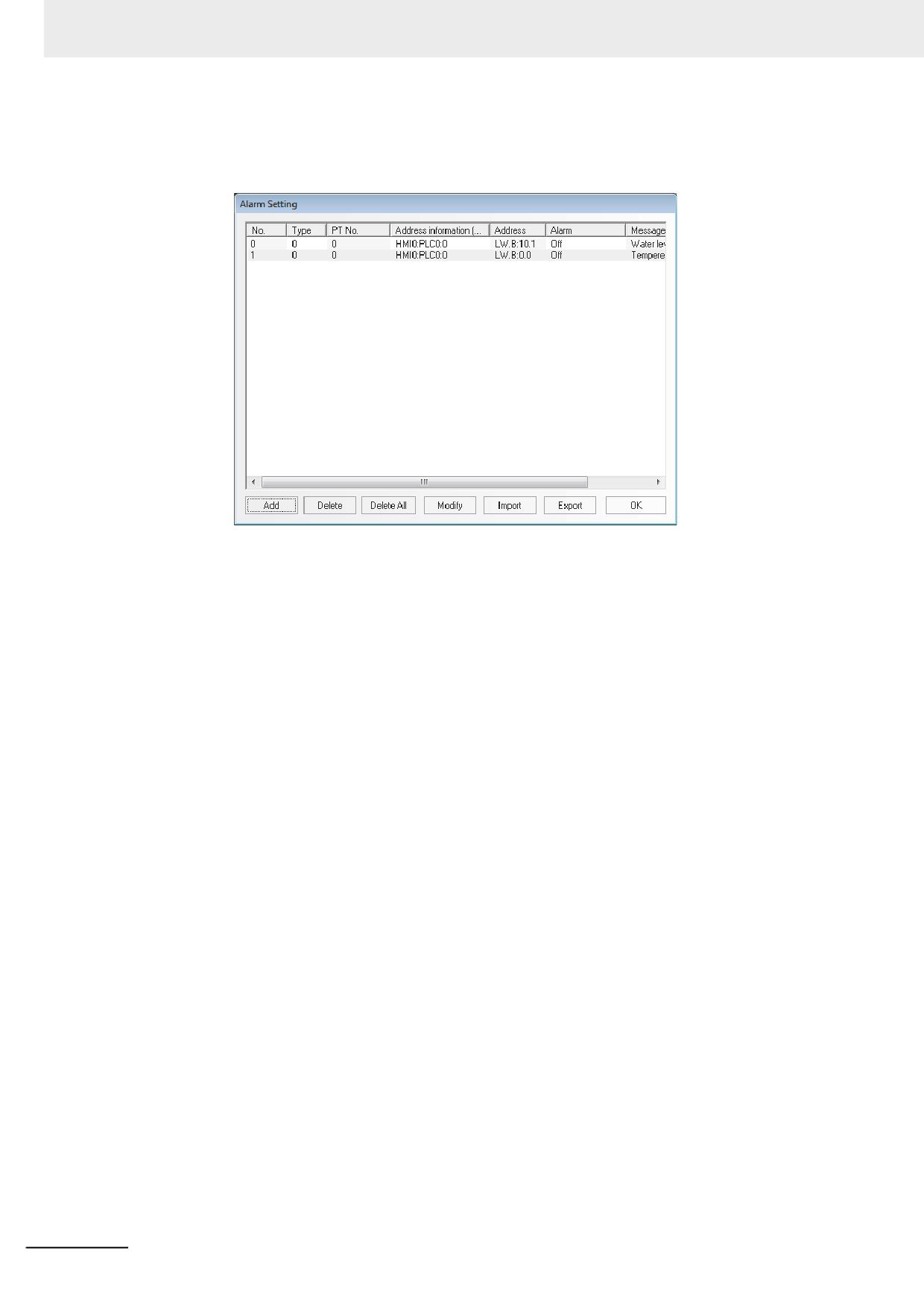
3 Functions of NB-Designer
3
Press the [OK] button to make the alarm setting displayed in the list. After the alarm setting is
logged, the existed alarm setting can be edited by [Delete] or modified by [Modify] buttons.
Press the [OK] button to complete the logon of the alarm setting.
Note In order to perform the communications effectively, specifying the continuous address is recommended as
read address of the alarm information. For example, when you specify the continuous addresses from M100
to M199, whole the addresses from M100 to M199 can be read in the communications only once.
Event/Alarm Type
The Event/Alarm is divided into 256 types, i.e. 0 to 255, in the NB-Designer.
Event, Alarm and Alarm Display can restrict the types of the displayed events respectively. For
example, if the display type of “Event Component” is specified from 0 to 3 in the [Event Setting] tab
of Event Properties, only the contents of event ranging from Type 0 to Type 3 will be displayed.
This option is used to select the type of the alarm and event displayed currently.
3-250
NB-series Programmable Terminals NB-Designer Operation Manual(V106)
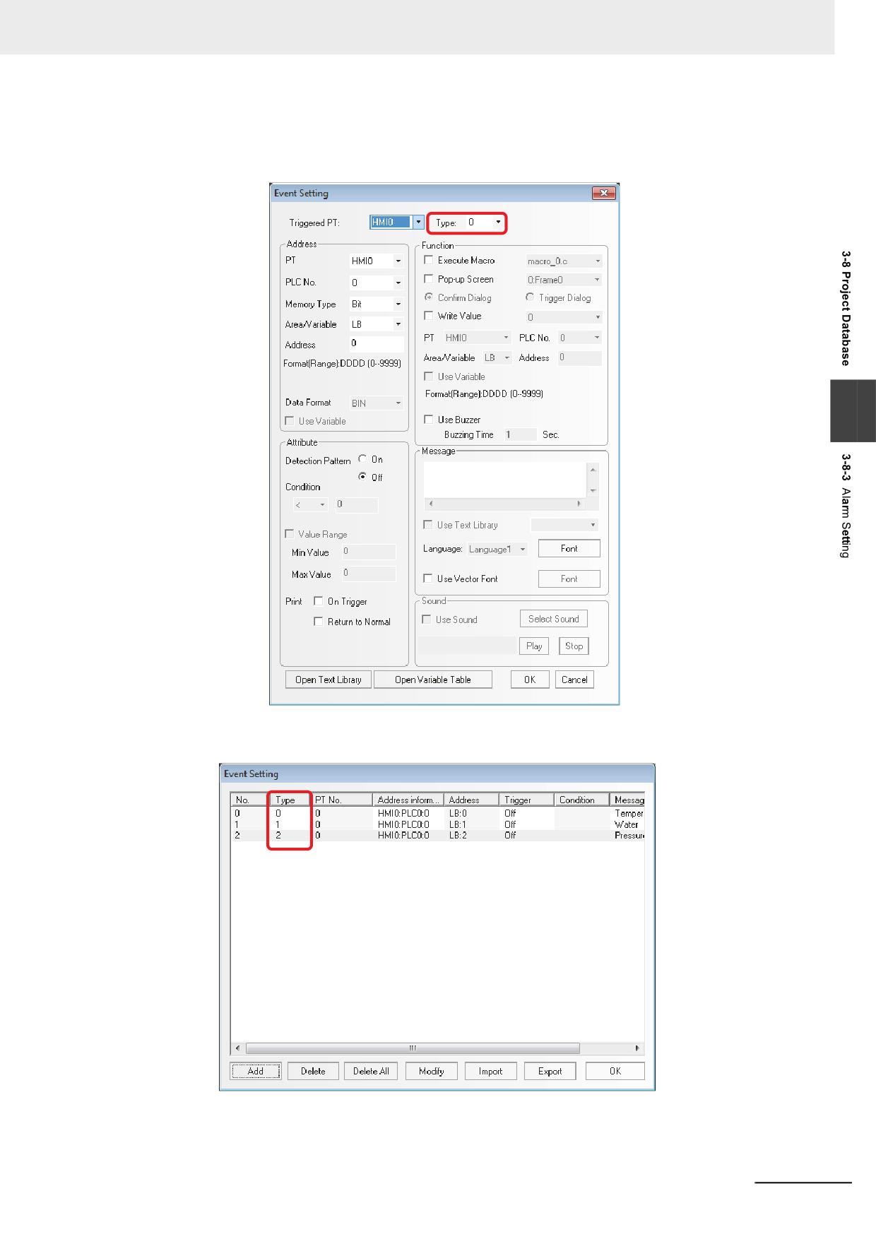
3 Functions of NB-Designer
Example: To create an event log with the type of each event being different.
(1) Click the [Event Setting] of the [Project Database] and open the [Event Setting] dialog box.
Click the [Add] and add a new event setting as below.
3
(2) Create the event triggered by the LB1 and LB2 in the same procedure as the LB0's. The
Type of the LB1 is specified to 1 and the Type of the LB2 is specified to 2.
NB-series Programmable Terminals NB-Designer Operation Manual(V106)
3-251
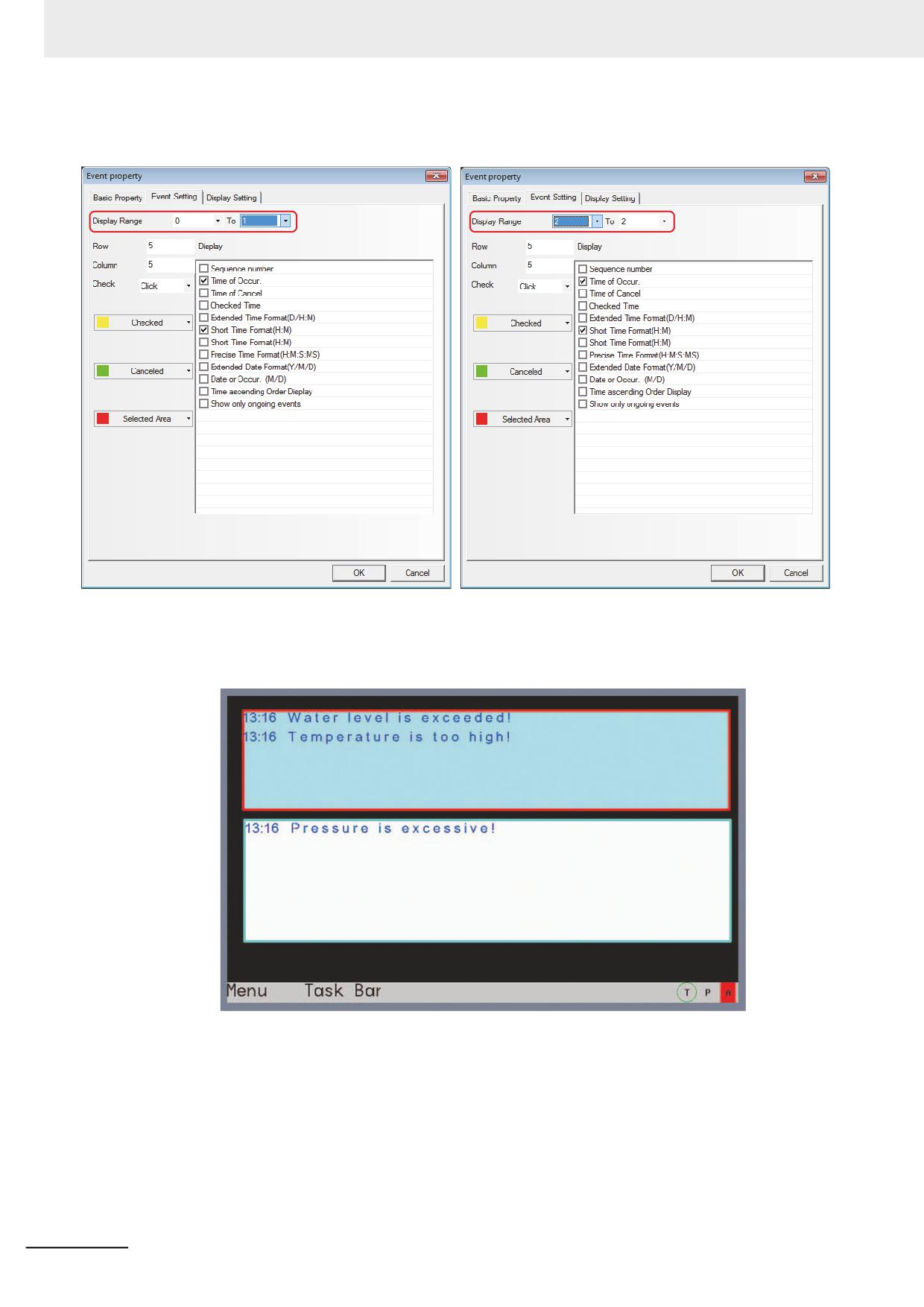
3 Functions of NB-Designer
(3) Place two Event components with the addresses of LW0 in the Edit Window and the
settings are as shown below.
Event display component 1
Event display component 2
(4) When the offline test is performed, the event with the format (type) 0 of ON and the trigger
for the LB0 and the format (type) 1 of ON and the trigger for the LB1 is displayed in Event
component 1 and the other event with the format (type) of ON and the trigger for the LB2 is
displayed in Event component 2.
3-252
NB-series Programmable Terminals NB-Designer Operation Manual(V106)
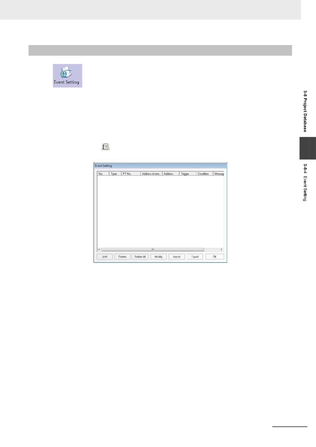
3 Functions of NB-Designer
3-8-4
Event Setting
The information logged in Event component will be displayed in the Event component. To
display the information in the Event component, the information must be logged in the [Event Setting]
database in advance. One bit or word address controls one piece of information. When the logged bit or
word address is triggered (i.e. It is ON/OFF or the restricted value is triggered.), the corresponding
information will be displayed in the Event component. (This component is only responsible for the event
log, and the display needs to be done by “Event” component.)
Process of Adding/Modifying Event Setting
1
Clicking the
icon located in Database Toolbar or “Event Setting” in the “Project Database”
3
allow “Event Setting” dialog box pops up.
NB-series Programmable Terminals NB-Designer Operation Manual(V106)
3-253
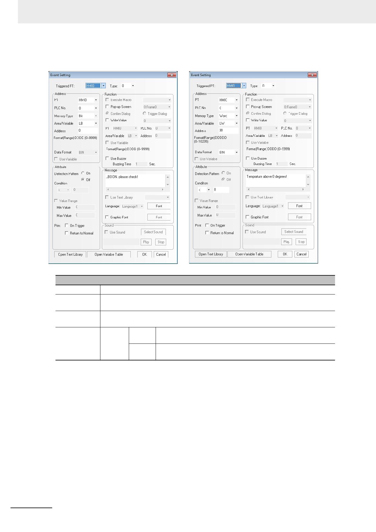
3 Functions of NB-Designer
2
Select the [Add] button to add the information or select the [Modify] button to modify the
existing information.
Descriptions of Event Information Properties
Triggered PT
Select one PT to specify the Event Setting when multiple PTs were registered to the project.
Type
Classifies the events and the available type is from 0 to 255. [Event Display] tab of the Event
Display component can restrict the displayed event type.
Address
Specify the register working as the trigger of the event. The type of memory can be changed
into “Bit” or “Word” through “Data Type”.
Attribute
Bit
ON
When the state of the bit address is turn from OFF to ON, one
specified event record will be displayed.
OFF
When the state of the bit address is turn from ON to OFF, one
specified event record will be displayed.
3-254
NB-series Programmable Terminals NB-Designer Operation Manual(V106)
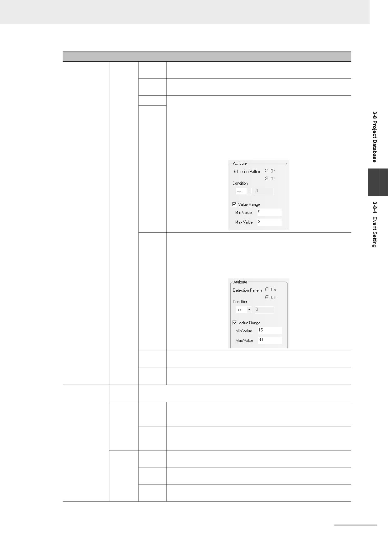
3 Functions of NB-Designer
Descriptions of Event Information Properties
Attribute
Word
<
When the value of the specified word address is less than the
specified value, one specified event record will be displayed.
>
When the value of the specified word address is greater than the
specified value, one specified event record will be displayed.
==
When the value of the specified word address is equal to the specified
value, one specified event record will be displayed.
[Value Range] When the value of the specified word address is within
the specified range, one event record will be generated. As shown
below, check “Value Range” with “Min Value” & “Max Value” set to “5”
and “10” respectively, if the value which is represented as N, of the
specified word address is larger than 5 and smaller than 10, one
specified event record will be displayed.
3
< >
When the value of the specified word address is not equal to the
specified value, one specified event record will be displayed.
As shown below, check “Value Range” with “Min Value” & “Max Value”
set to “15” and “30” respectively, if the value which is represented as
N, of the specified word address is less than 15 or larger than 30, one
specified event record will be displayed.
< =
When the value of the specified word address is less than or equal to
the specified value, one specified event record will be displayed.
> =
When the value of the specified word address is greater than or equal
to the specified value, one specified event record will be displayed.
Function
Execute
When event occurs, the selected Macro will be executed. *
Macro
Pop-up
Confirm
Touching the event information displayed in the event component, the
Screen
Dialog
specified screen will pop up. And it needs to use the “Close Screen”
function of the Function Key to close this Pop-up Screen.
Trigger
The specified screen will pop up when the event occurs. And it needs
Dialog
to use the “Close Screen” function of the Function Key to close this
Pop-up Screen.
Write
0
When the event log occurs, the state of the specified bit memory will
Value
be set to “0”.
1
When the event log occurs, the state of the specified bit memory will
be set to “1”.
Not
When the event log occurs, the state of the specified bit memory will
be reversed.
NB-series Programmable Terminals NB-Designer Operation Manual(V106)
3-255
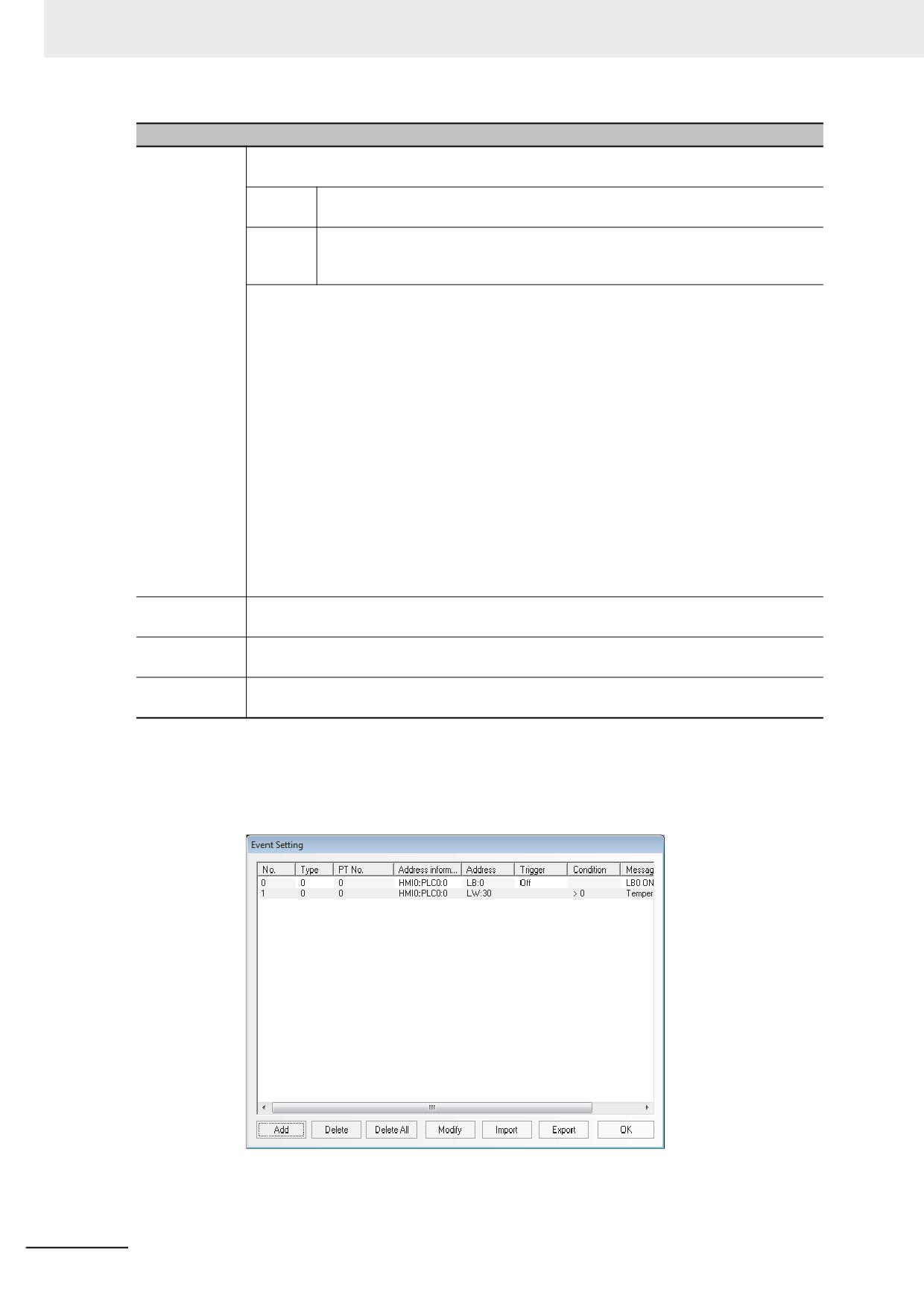
3 Functions of NB-Designer
Descriptions of Event Information Properties
Message
Inputs the contents of event or event display to be displayed. Clicking [Font] can set the
Font Type and the related attributes.
Use Text
Determines whether to use the contents logged in the Text Library.
Library
Language
When using multi-language Text Library, you can select the language displayed
as the event information here and click “Font” to set the font Property
corresponding to text in each kind of language respectively.
TIP: The data and others stored in internal memory LW can be displayed in the event
information.
The available formats are follows:
• %h:mm:s#:
The Time of Occur. is indicated.
• %y:mm:d#:
The Date of Occur. is indicated.
• %nnfmd:
“%” represents the start symbol, “nn” represents the addresses of the internal memory LW
from 00 to 99.
“f” represents that the displayed number includes the decimal part.
“m” represents the digit of the decimal digit.
“d” represents the end symbol.
If “%nnd” is entered, the value excluded the digit of decimal digit will be displayed. For
example, if you want to display the value stored in LW20 with one decimal digit, enter
“%20f1d”. If the stored value in the PLC memory should be displayed, transferred it to
internal memory LW to display it.
Use Buzzer
When the event is triggered, the buzzer will be enabled. The Buzzing Time can be set with
the unit of “second”.
Open Text
Opens the text library editing dialog box.
Library
Open Variable
Open the variable editing dialog box.
Table
* Please refer to 3-9-3 Macro Triggering (Page 3-273).
3
Clicking [OK] allows the specified event setting added in the List of the [Event Setting] dialog
box. The registered event setting can be deleted by [Delete] button or modified by [Modify]
button. Click [OK] button to finish the registration of the event setting.
Note In order to perform the communications effectively, specifying the continuous address is recommended
as read address of the Event Setting. For example, when you specify the continuous addresses from
M100 to M199, whole the addresses from M100 to M199 can be read in the communications only once.
3-256
NB-series Programmable Terminals NB-Designer Operation Manual(V106)
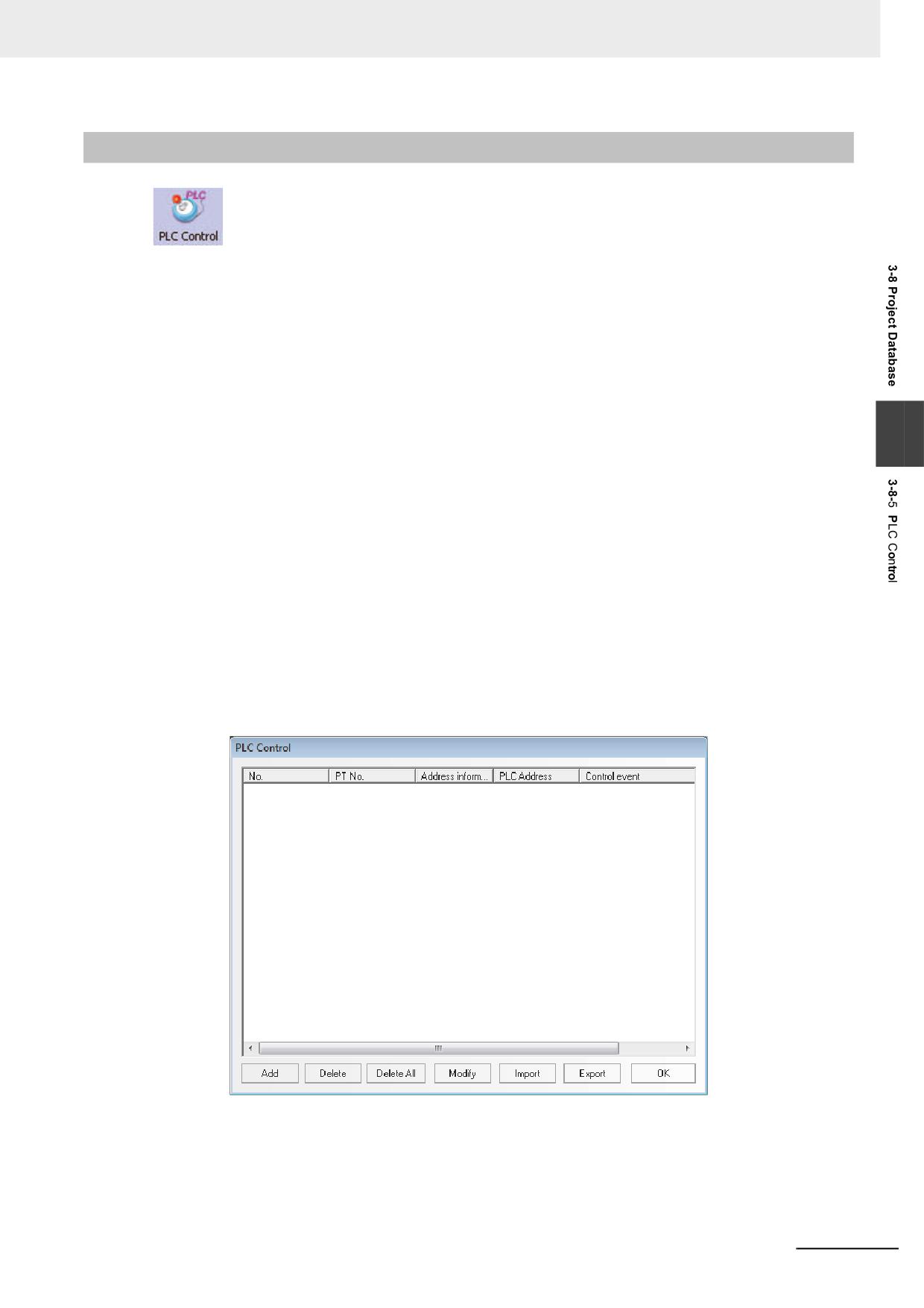
3 Functions of NB-Designer
3-8-5
PLC Control
When the corresponding control is triggered, PLC Control component can activate one
specific operation.
PLC Control component is a powerful component group, which can realize a large variety of functions
because it is more powerful than the general component. And its functions are as follows:
(1) Switch Screens: Changes the current screen.
(2) Write data (current base screen number) into PLC: Transfers the current Screen No. to the PLC.
(3) General-purpose PLC control: Realizes the data transmission between the PLC address and
LW/RW.
(4) Backlight Off: Turns off the backlight.
3
(5) Backlight Off (Write Back): Turn OFF the back light. (The control bit will be reset.)
(6) Execute Macro: Executes the corresponding Macro number when the condition is met.
(7) Backlight On: Turns on the backlight.
(8) Backlight On (Write Back): Turn ON the back light. (The control bit will be reset.)
(9) General PLC Control (Expansion)
(10) Change Screen (Ignore screen 0)
Note Do not specify the same address in the functions of Switch Screens, Change Screen (Ignore screen 0), and
Write data (current base screen number) into PLC.
Process of creating one PLC Control
1
Press the PLC Control icon to make the list of PLC Control pop up.
2
Press “Add” button to create a new PLC Control or press “Modify” and “Delete” buttons to
modify the PLC Control and delete the selected setting respectively.
NB-series Programmable Terminals NB-Designer Operation Manual(V106)
3-257
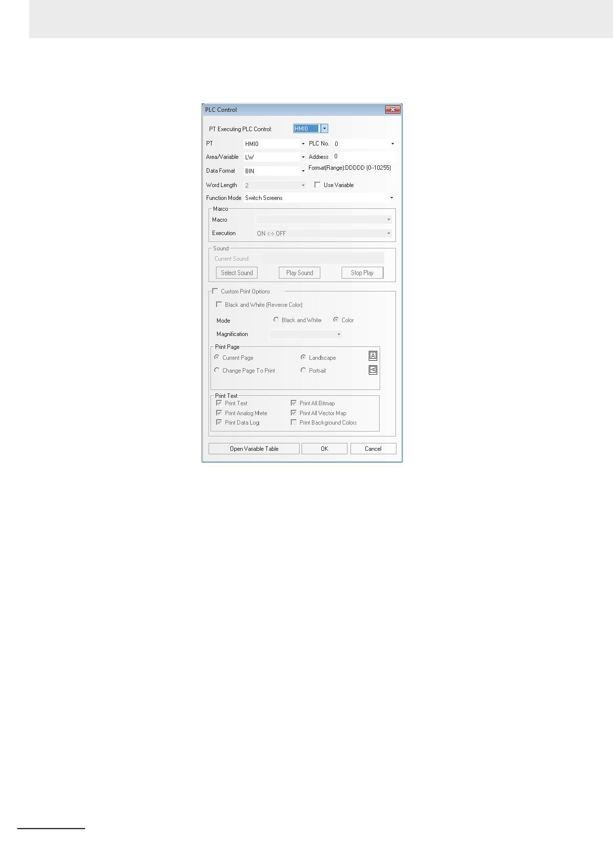
3 Functions of NB-Designer
3
Specify the options displayed in the PLC Control dialog box correctly.
Area/Variable: Specifies the Area/Variable of the devices performing the PLC control
operations.
Address: Specifies the addresses of the devices performing the PLC control operations.
Data Format: Includes BIN or BCD.
Function Mode: Specifies the operation types of the setting. There are 12 types available, and
their functions will be described later in details.
Macro: Sets the No. of Macro program to be executed when the Function is “Execute Macro”.
4
Press the “OK” button to exit from the PLC Control dialog box.
5
Repress the “OK” button to exit from the list of PLC Control.
3-258
NB-series Programmable Terminals NB-Designer Operation Manual(V106)
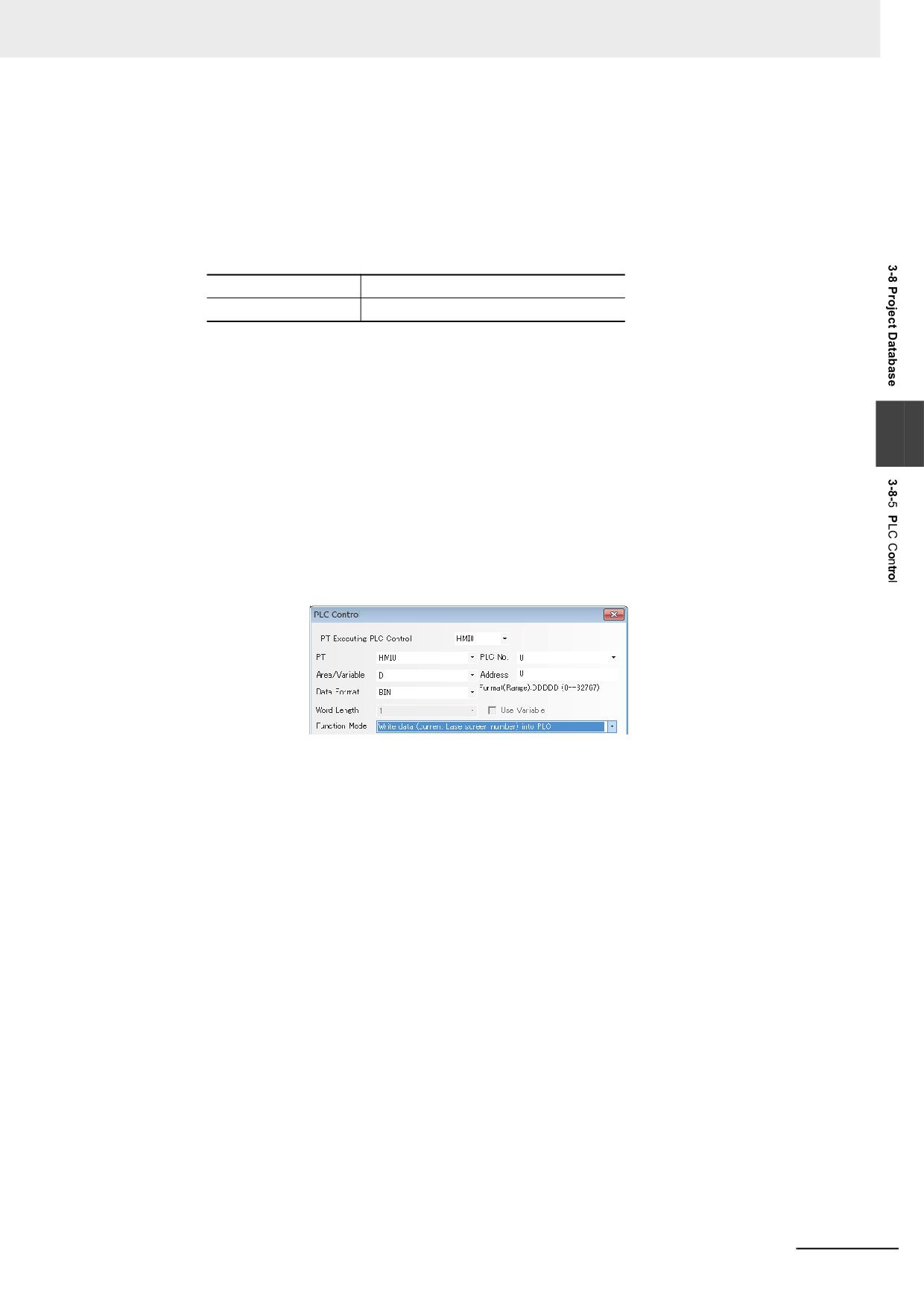
3 Functions of NB-Designer
Function Mode
1
Switch Screens
This operation needs 2 consecutive word addresses. When the [Read Address] is switched to
a valid screen No., the current screen will be closed and the specified screen will appear.
Specify the number in the destination screen in the [Read Address]. The number after
switching will be written in [Read Address + 1]
Read Address
For screen switching control
Read Address + 1
No. of the destination screen
For example, set the address to “DM0”, Data Format to “BCD” and the current screen to Frame
0. If DM0 is changed to 10, the current screen will be switched to Frame 10, and 10 will be
returned to DM1.
Note Each time the [Change Screen] Function Key is pressed, the current screens is closed and the
destination screen is displayed. The function of [Switch Screens] of the PLC control is similar to the
3
[Change Screen] function of the Function Key. Their difference is the respect whether function is operated
by touching the screen or it is performed by the PLC memory control. When the value of Read Address is
modified to an available screen No., the current screen will be closed and the screen specified with the
Read Address will be displayed. Then the content of the Read Address in written in the Read Address +
1. This operations can be executed only when the Read Address is modified.
2
Write Data (Current Base Screen No.) into PLC
The number of the base screen currently displayed will be notified to the PLC.
When there is a PLC Control with the settings shown as above, word address DM0 will store
the No. of the current base screen.
3
General PLC Control
The data transmission between the PLC and the PT can be controlled.
It can be divided into 4 types according to the direction of data transmission:
(a) PLCRW (Recipe Data Memory), type code 1.
(b) PLCLW (Local Data memory of PT), type code 2.
(c) RW (Recipe Data memory)PLC, type code 3.
(d) LW (Local Data memory of PT)PLC, type code 4.
The specific instructions are as follows:
Select “General PLC Control” as “Control Type” in PLC Control setting dialog box, and select
the data area and the address of the data transmitted by the [Read Address]. Please note that
the unit must be “word”, and the system automatically allocate 4 continuous addresses, which
are used as the controlling addresses of the data transmission. And the specific meanings and
usage methods are as follows:
(1) Read Address: Select the 4 types of execution type codes. When new value is written to the
memory, the system execute the corresponding transmission function. After the
transmission is detected, the memory will be reset to 0.
(2) Read Address + 1: Specify the size of the data transmitted. The number of the word
specified at this moment will be transmitted.
NB-series Programmable Terminals NB-Designer Operation Manual(V106)
3-259
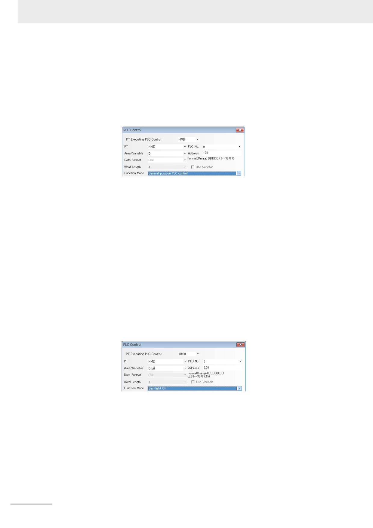
3 Functions of NB-Designer
(3) Read Address + 2: Specify the offset of the transmitted data address of the PLC side. The
offset is specified from the address of [Specified Read Address + 4].
For example, if the Read Address set in the PLC General Control is DM100, and the data
contained in memory DM102 is 4. The starting address of the transmitted PLC data is
DM108 = [(100 + 4) + 4].
(4) Read Address + 3 : Specify the offset of the transmitted data address at the sides of local
memory (LW) of the PT or Recipe data memory (RW)
In the example listed above, if the data contained in DM103 is 100, the starting address of
the transmitted PT data operated during the transmission is RW (LW)100=(0 + 100).
Here is the procedure which uses the PLC control, to transmit the data includes 30 words
starting from DM100, to the data block of the same size starting from RW200 in the Recipe
Data memory of the PLC.
(1) Firstly, specify the PLC control component set with [General-purpose PLC Control] for the
control select and DM10 for [Read Address].
(2) Secondly, specify the size of the data and the offset address of the controlling data. DM11 is
specified to 30 (it means the number of transmitted words is 30 words.) DM12 is specified
to 86 (the starting address is DM100=(10+4+86) in the PLC and DM13 is specified to 200
(the destination address is RW200=(0+200), respectively.
(3) Finally, specifying the execute type code according to the direction of the data transmission
allows the data transmission. If DM10 is specified to 1, the number of the specified data will
be transmitted from the starting address of the PLC to the Recipe Data memory of the PT. If
DM10 is specified to 3, the direction to transmit the data will be reversed.
The other transmission to two destinations are performed in the same procedure as above.
4
Backlight Off
This operation uses one bit address to control the closing of the backlight, and when the bit
address is ON, the backlight will be closed.
In the settings shown as above, when D_bit0.00 is ON, the backlight turns off. In this case,
when the user touches the PT, the backlight will automatically light on, and at this time the
D_bit0.00 is still ON. If the user touches the D_bit0.00 again, it will be turned OFF, thus
returning to the state before the backlight is closed.
3-260
NB-series Programmable Terminals NB-Designer Operation Manual(V106)
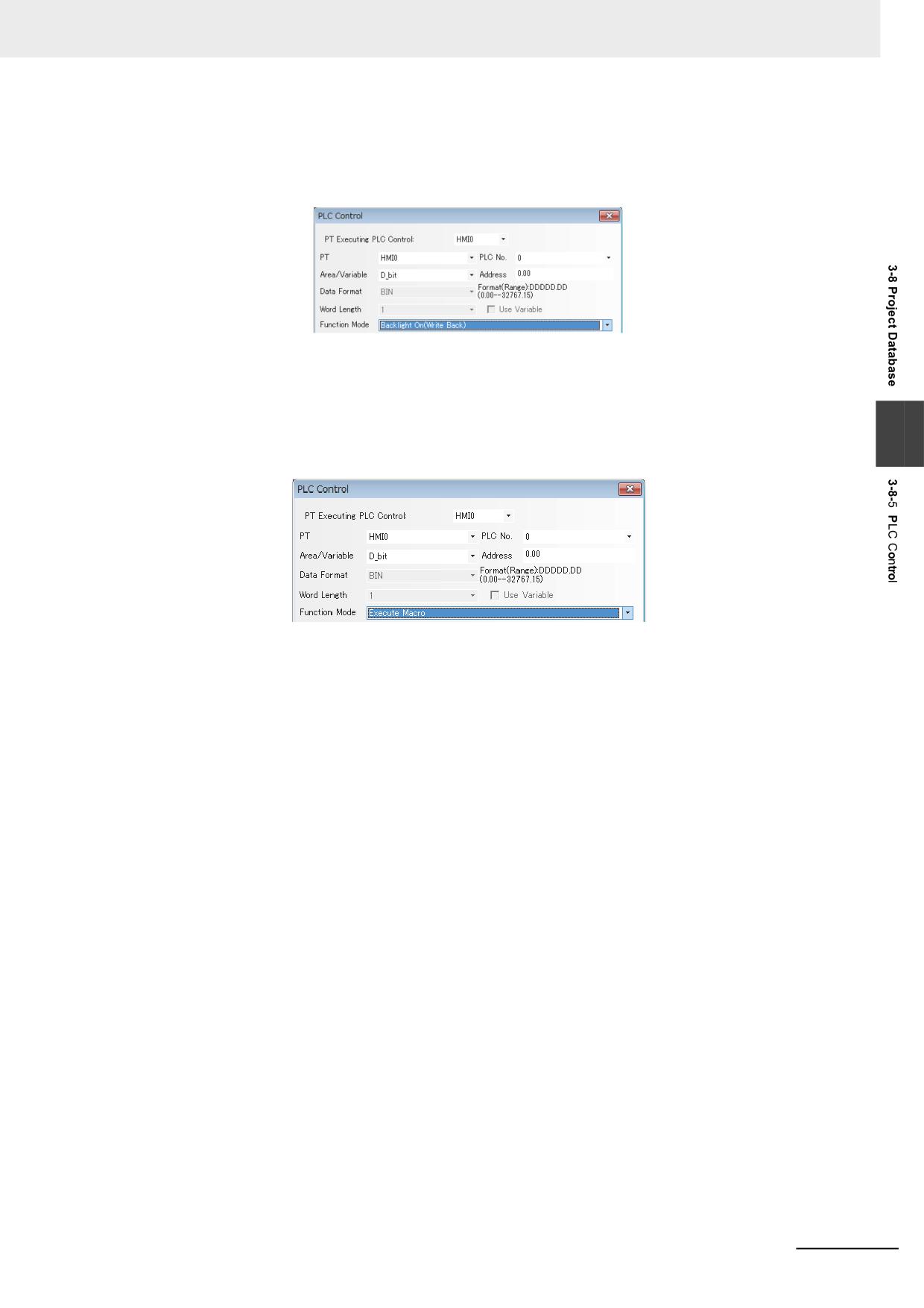
3 Functions of NB-Designer
5
Backlight Off (Write Back)
The operation of this option is similar to [Backlight Off], but the address of this bit of PLC will be
cleared to 0 while as well as the back light turns Off and then the bit address turns ON.
In the settings shown as above, when D_bit0.00 turns ON, the backlight is OFF, and D_bit0.00
is automatically turned OFF. When the user touches the PT, the backlight turns ON and
D_bit0.00 remains OFF.
6
Execute Macro
3
When the state of the specified bit address is ON, the selected Macro ID will be triggered.
Area/Variable and Address: Refers to the address to trigger the Macro program execution.
The Macro program will be executed when this bit is 1, while not executed when this bit is 0.
Macro ID: Select a Macro to be executed.
Execute Method:
ONOFF: When the specified bit turns OFF from ON or vice versa, the Macro will be
executed.
OFFON: When the specified bit turns ON from OFF, the Macro will be executed.
ONOFF: When the specified bit turns OFF from ON, the Macro will be executed.
ON: When the specified bit is ON, the Macro will be executed.
OFFON, Reset: When the specified bit turns ON from OFF, the Macro will be executed and
the specified bit will be forced into OFF.
ONOFF, Reset: When the specified bit turns OFF from ON, the Macro will be executed and
the specified bit will be forced into ON.
Note Only when the Macro is added within the project, this function is available. If the Macro code is
removed after specifying the “Execute Macro” in the Function Mode option the PLC Control dialog
box by the Function selection, the code is converted automatically to the Macro in the default. If the
Macro does not exist, [Macro] column is left to blank as the default.
NB-series Programmable Terminals NB-Designer Operation Manual(V106)
3-261
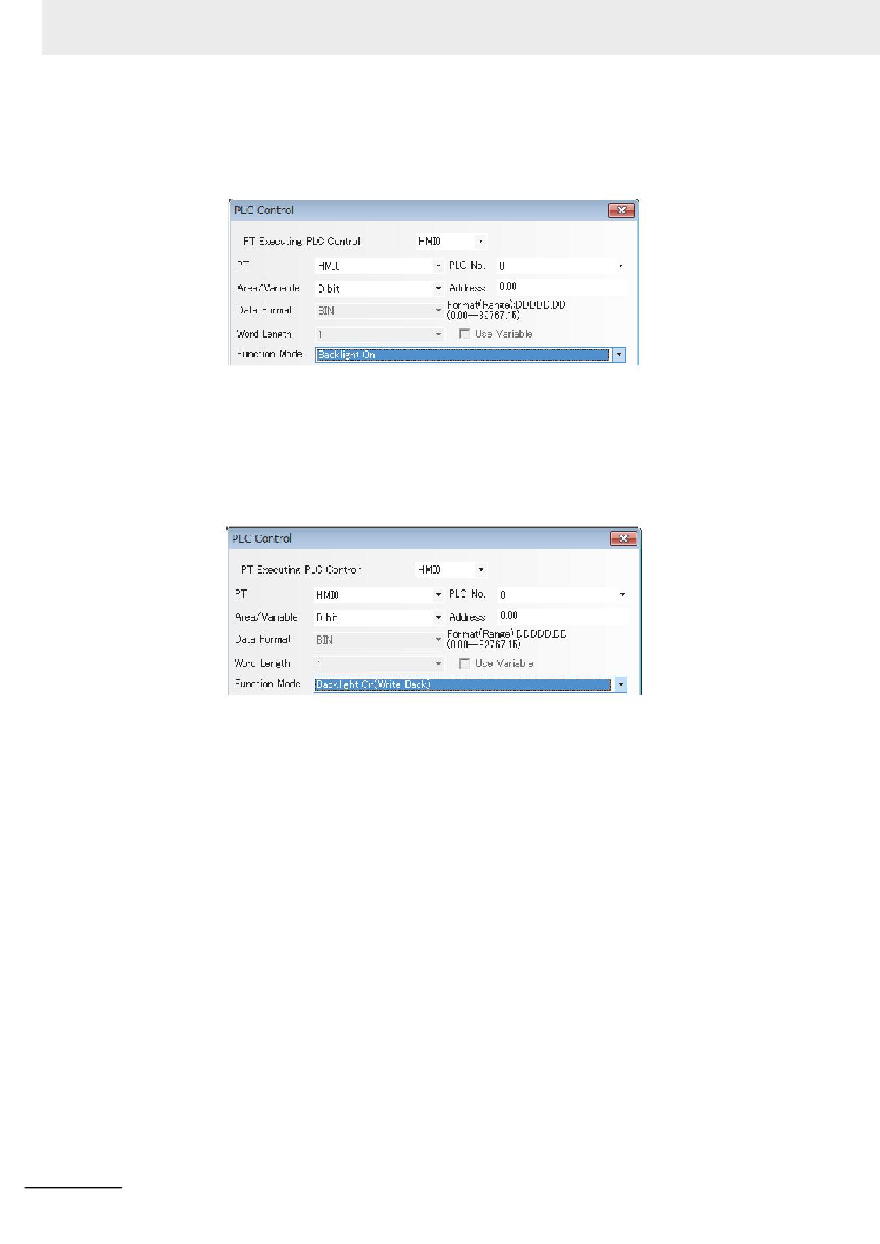
3 Functions of NB-Designer
7
Backlight On
This operation uses one bit address to control the lighting of the backlight, and when the bit
address is ON, the backlight turns ON.
In the settings shown as above, when D_bit0.00 is ON, and the back light will turn ON. If the
user touches D_bit0.00 again, it will turn OFF, thus returning to the state before the backlight
lights on.
8
Backlight On (Write Back)
The operation of this option is similar to [Backlight On], but the address of this bit of PLC will be
cleared to OFF while the bit address turns ON.
In the settings shown as above, D_bit0.00 turns OFF automatically as well as the back light
turns ON when the D_bit0.00 turns ON.
3-262
NB-series Programmable Terminals NB-Designer Operation Manual(V106)
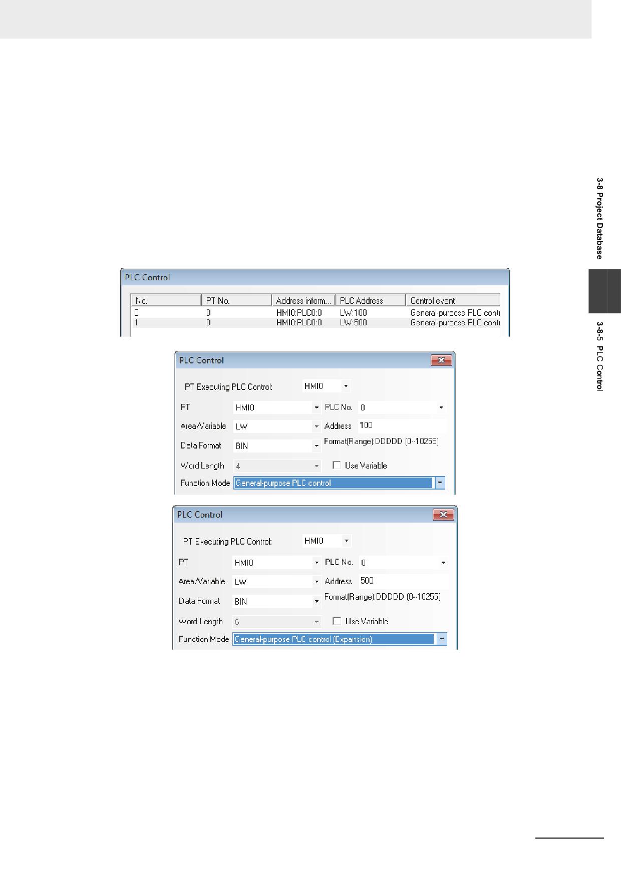
3 Functions of NB-Designer
9
General-purpose PLC Control (Expansion)
General PLC Control (Extend) is similar to General PLC Control, but the occupied address is
different, i.e. General PLC Control occupies 4 words while General PLC Control (Extend)
occupies 6 words (extending “word” to “double-word”). Refer to the section of General-purpose
PLC Control for the details.
The method is as follows:
(1) Read Address: Similar to General-purpose PLC Control.
(2) Read Address + 1: Similar to General-purpose PLC Control.
(3) Read Address + 2: Refers to the address offset of the data memory of PLC during the
transmission and it occupies 2 words. Please note that this offset is specified from the
address memory with “Read Address + 6”.
(4) Read Address + 4: Refers to 2 words occupation.
3
NB-series Programmable Terminals NB-Designer Operation Manual(V106)
3-263
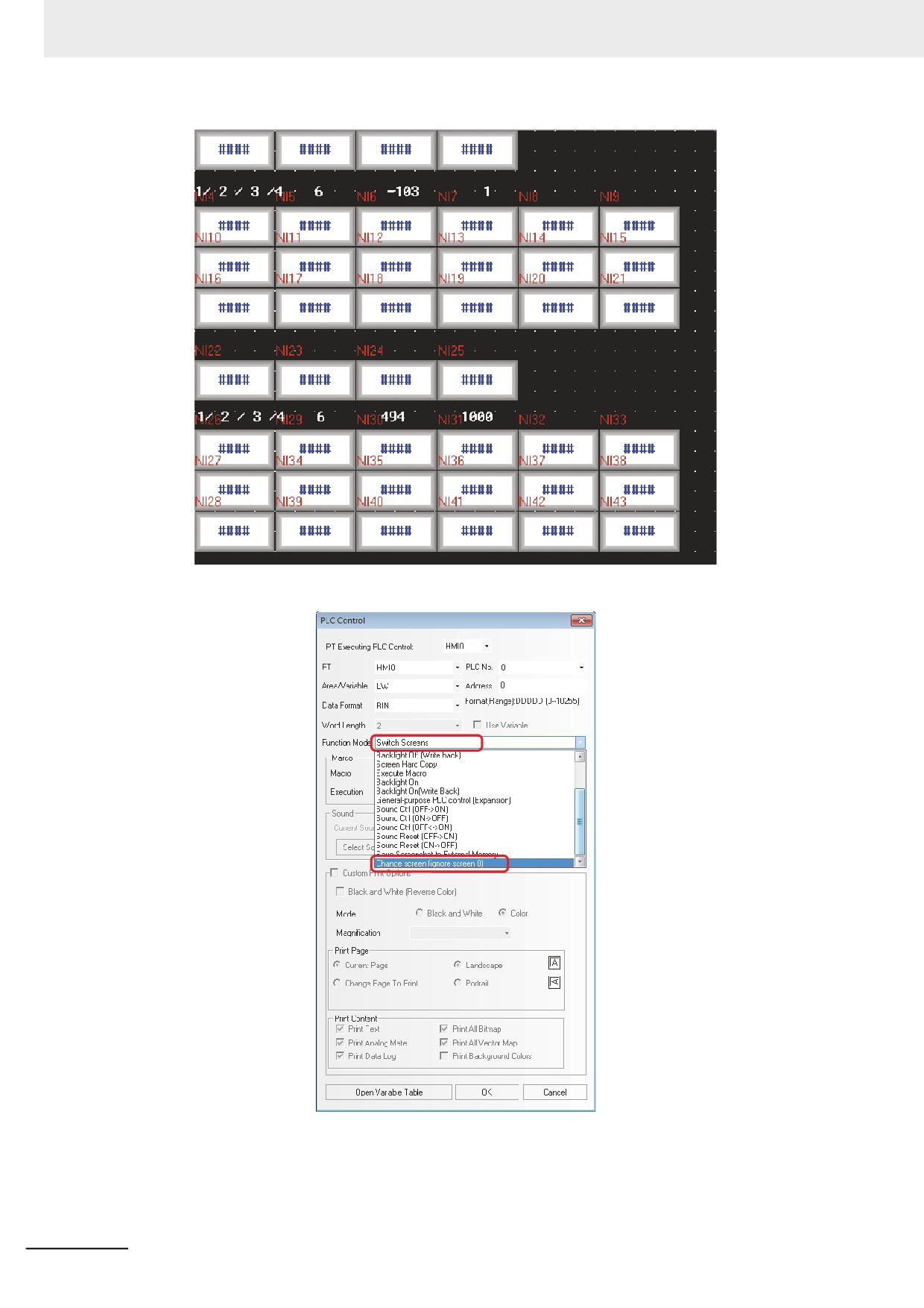
3 Functions of NB-Designer
10 Change Screen (Ignore screen 0)
The difference between Switch Screens and Change Screen (Ignore screen 0) is as follows:
Switch Screens: When the value of specified address is 0, it will be switched to Screen 0.
Change Screen (Ignore screen 0): When the value of specified address is 0, screen
switching is not made.
3-264
NB-series Programmable Terminals NB-Designer Operation Manual(V106)
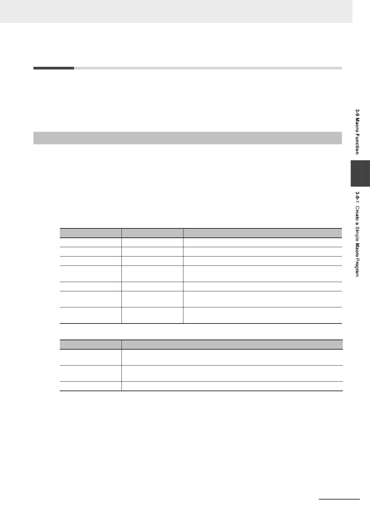
3 Functions of NB-Designer
3-9
Macro Function
Macro is the function allows the user to create and execute the simple and original programs.
The user can add the functions such a arithmetical operations or discriminant of the conditions which
are not be supported by the basic functions of the NB-Designer. Using the Macro function, the user also
convert the display processing in the screen or the data processing used to be performed in the PLC.
This function allows the PC loading reduced. The Macro of the NB-Designer conforms to C Language
(ANSI C89).
3-9-1
Create a Simple Macro Program
This section provides a brief of the Macro variables.
The Macro variables are classified into two types such as internal variables and external variables.
• Internal variables: The variables are available only within the Macro Program. The internal variables
3
can be defined in the [Macro Variable Table] or the [Macro Editing Window].
• External variables: The variables are to read and write the values with the external controllers. The
external variables are necessary to be defined in the [Macro Variable Table] in
advance. The defined external variables can be used in the [Macro Editing Win-
dow].
Storage Format of the variables used in the [Macro Variables Table]
Storage Format
Data length
Descriptions
Bit
1bit
Bit variable with 2 statuses of 0 and 1.
Signed short
1 word (16 bits)
Signed short-integer variable with a range of -32768 to 32767.
Unsigned short
1 word (16 bits)
Unsigned short-integer variable with a range of 0 to 65535.
Signed int
2 word (32 bits)
Signed-integer variable with a range of -2147483648 to
2147483647.
Unsigned int
2 word (32 bits)
Unsigned-integer variable with a range of 0 to 4294967295.
Float
2 word (32 bits)
Single-precision floating-point variable with a range of
-3.4E+38 to +3.4E38
Double
4 word (64 bits)
Double-precision floating-point variable with a range of
-1.79E+308 to +1.79E+308
Read/Write type of Macrocode Variable
Read/Write Type
Descriptions
Read
The values of Macro are read before being executed, and reading operation is not
performed during Macrocode execution.
Write
The values of Macro are written to the specified variable at one time after being
executed, and writing operation is not performed during Macrocode execution.
Read/Write
The values of Macro are read before being executed, and written after being executed.
NB-series Programmable Terminals NB-Designer Operation Manual(V106)
3-265
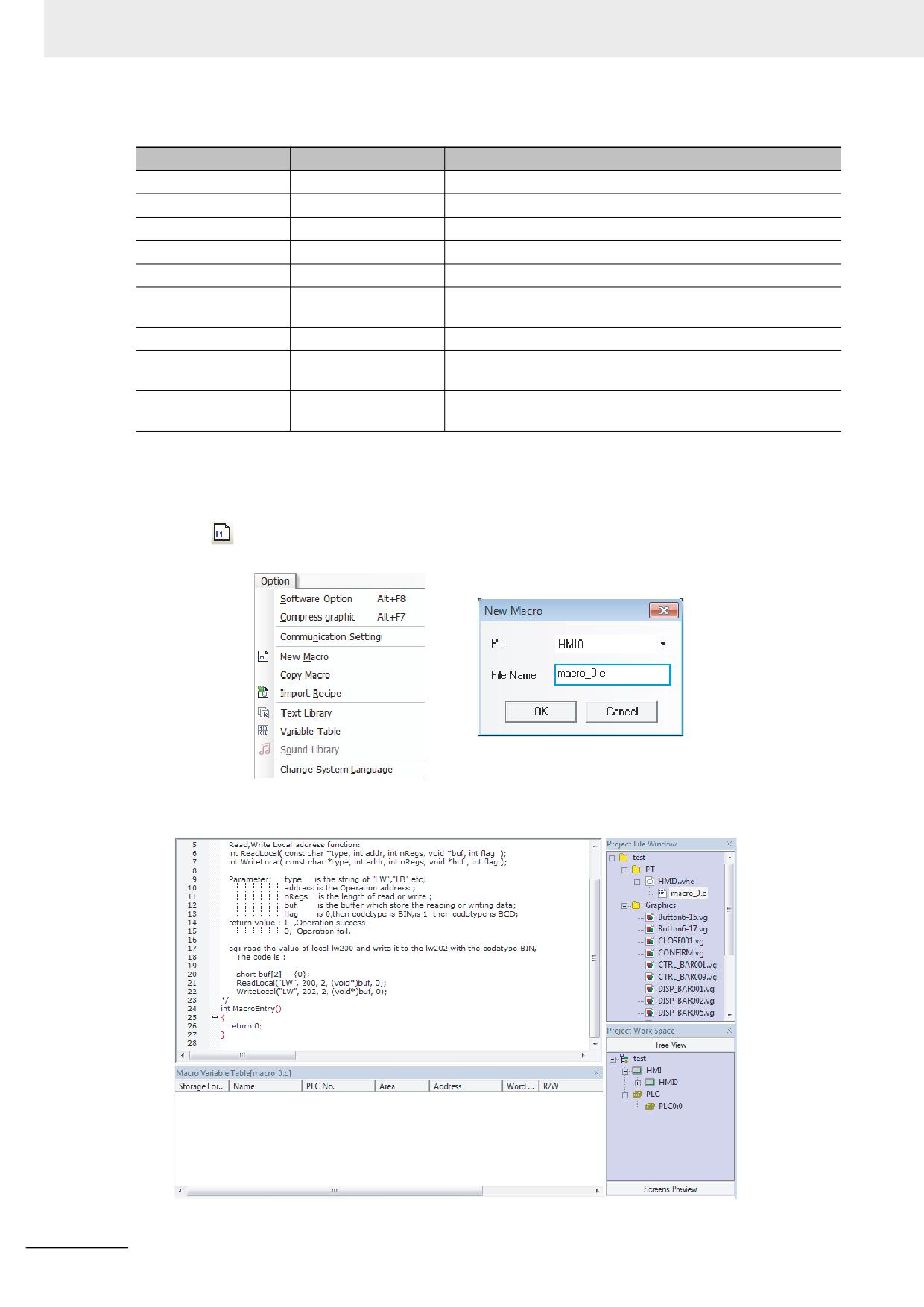
3 Functions of NB-Designer
Storage Format used in Macro Variable
Data Type
Data length
Descriptions
Bool
1bit
Bit variable with 2 statuses of 0 and 1.
(Signed) char
1byte(8bit)
Signed short-integer variable with a range of -128 to 127.
Unsigned char
1byte(8bit)
Unsigned short-integer variable with a range of 0 to 255.
(Signed) short
1word (16bits)
Signed short-integer variable with a range of -32768 to 32767.
Unsigned short
1word (16bits)
Unsigned short-integer variable with a range of 0 to 65535.
(Signed) int
2word (32bits)
Signed-integer variable with a range of -2147483648 to
2147483647.
Unsigned int
2word (32bits)
Unsigned-integer variable with a range of 0 to 4294967295.
Float
2word (32bits)
Single-precision floating-point variable with a range of
-3.4E+38 to +3.4E38
Double
4word (64bits)
Double-precision floating-point variable with a range of
-1.79E+308 to +1.79E+308
Create a Macro program with basic arithmetical function in the following figure.
Read 2 signed data from LW0 and LW1, make LW0 divided by LW1, then place the result of the division
in the 4 words from LW2 to LW5.
Press the
(Add Macro) icon in the database toolbar, or click [Macro] in the [Option] menu, then the
following dialog box will pop up.
Select the PT No. and input the file name, then click “OK” to enter the Macro Editing Window (i.e.
[macro_0.c]), as shown below.
3-266
NB-series Programmable Terminals NB-Designer Operation Manual(V106)
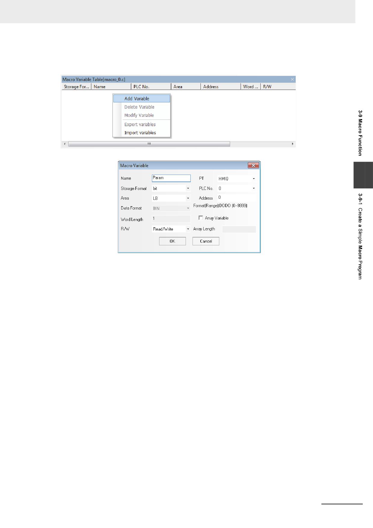
3 Functions of NB-Designer
Before writing the Macro, please predefine the I/O variables.
Right-click the mouse in the “Macro Variable Table [macro_0.c]” window to make the following menu
pop up.
Select “Add Variable” to make the following dialog box pop up.
3
Firstly specify the variable name.
There are 3 kinds of variables - Read variable, Write variable and Read/Write variable. Read variable
means Macro will obtain the value of the variable from the specified address; Write variable means the
result after the Macro executed will be written into the specified address and Read/Write variable
incorporates the features of the Read variable and the Write variable. Therefore, Read, Write and
Read/Write are the 3 different variables for the same address. It is recommended to use _R, _W and
_RW to differentiate the variables when you specify their names.
In the following example, LW0 and LW1 are Read variables and LW2 is Write variable, so we name
them as follows:
LW0_R, LW1_R, and LW2_W. Please note that the regulations for the variable names are consistent
with that for C language, and the special attention must be paid to the following points:
(1) The variable name is case-sensitive;
(2) The variable name can’t be the number or begin with the number or include some special
characters such as space, slashes etc.
(3) The variable name can’t be any reserved words of C language.
(4) Specify the array length in the range from 2 to 1024. The array length of the value in unsigned short
type cannot be specified to 4. The array length of the value in int type or float type cannot be
specified to 2. (The specification of the function is different from the one of the standard C
language)
NB-series Programmable Terminals NB-Designer Operation Manual(V106)
3-267
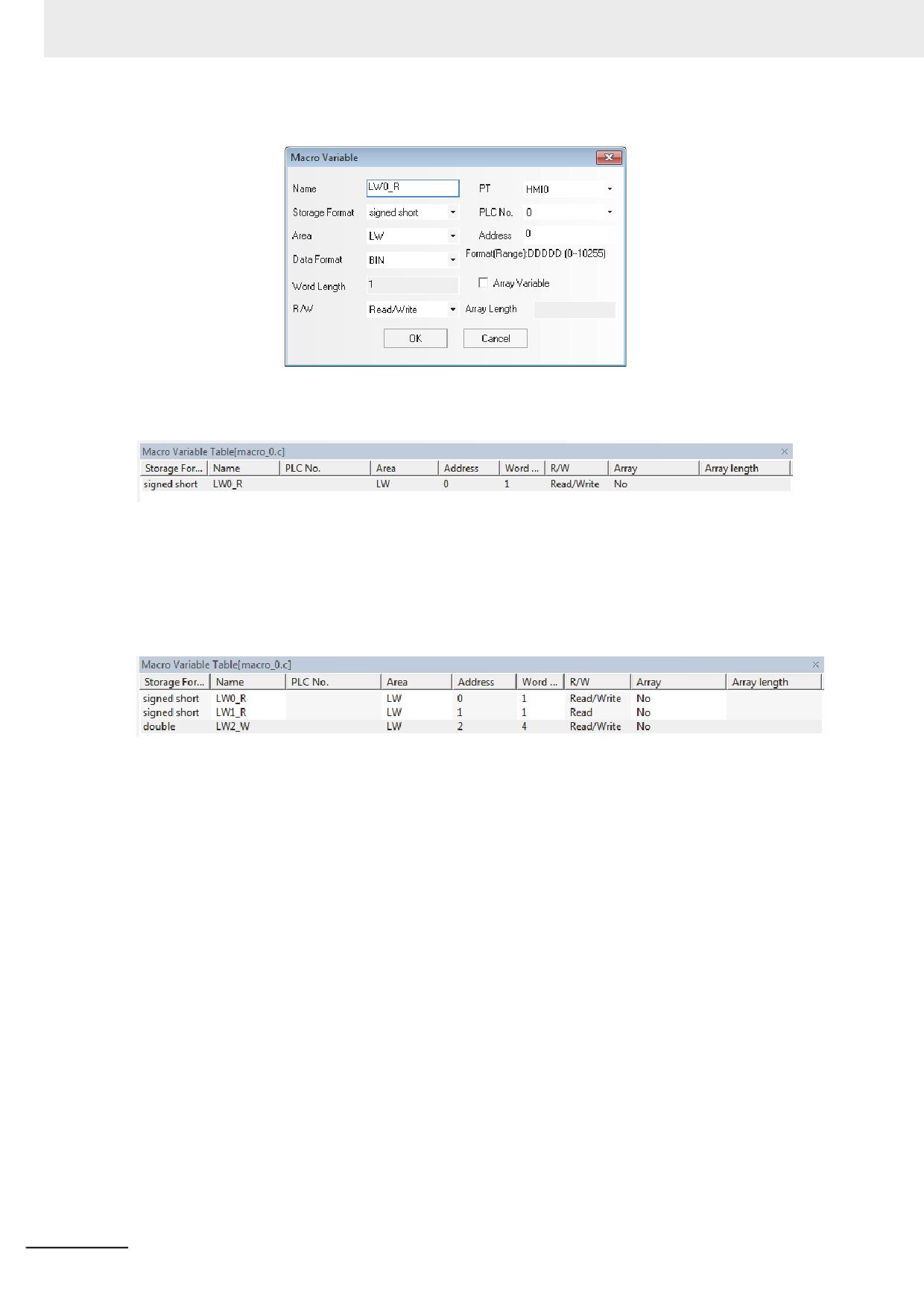
3 Functions of NB-Designer
In the example below, the Properties of LW0_R are set as follows:
Here, specify “signed int.” from “Storage Format”, “Read” from “R/W”, “LW” from “Area” and “0” from
“Address” respectively. After the specification, click the “OK” button, then this variable will be seen in
“Macro Variable Table [macro_0.c]” window.
Note The variables used in the Macro are necessary to be registered to the [Macro Variables Table] in advance.
Specify LW1_R and make its address to LW1, then set the address of LW2_W to LW2 by the same
method.
Note When the Storage Format is set to “double”, the Word Length will automatically become 4, i.e. this variable
will occupy LW2 to LW5.
After the completion of setup, the “Macro Variable Table [macro_0.c]” window is shown as below:
After defining the variables, we should write the following Macro:
int MacroEntry()
{
//LW0 is divided by LW1and LW2 is obtained
LW2_W=LW0_R/LW1_R;
return 0;
}
Once it is saved, the simple Macro is completed. At this time, go to the Edit Window to make the
editions as shown below:
Place 2 Number Input components corresponding to LW0 and LW1 respectively;
Place 1 text component and enter “/” to represent division.
Place 1 Number Display component corresponding to LW2, and set the Storage Format to “double” (i.e.
double-precision floating-point) and both the Integer and Decimal to “4”;
3-268
NB-series Programmable Terminals NB-Designer Operation Manual(V106)
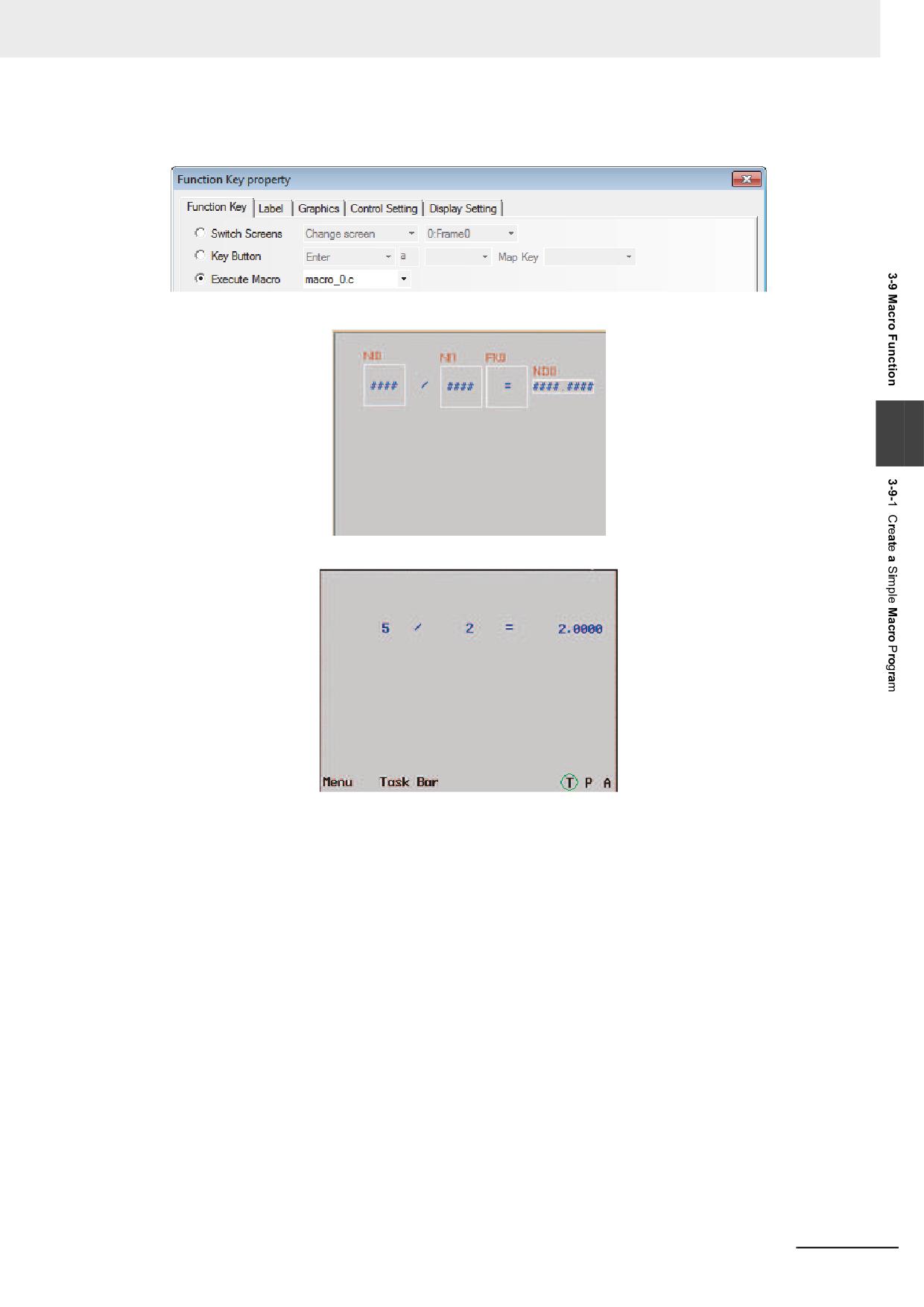
3 Functions of NB-Designer
Place 1 Function Key to execute Macro, and select “macro_0.c” in the drop-down menu as below and
input “=” in the label:
The Edit Window is displayed as follows.
3
Perform the offline test, input 5 into LW0 and 2 into LW1, and you will see the result as shown below:
The result should be 2.5000 instead of 2.0000.
LW0_R and LW1_R are [signed short] so that the division of one variable by another variable both in
integer type results in the variable also in integer type. In order to resolve this problem, the variable to
perform the division is necessary to be casted in [double] as follows.
LW2_W = (double)(LW0_R)/LW1_R;
NB-series Programmable Terminals NB-Designer Operation Manual(V106)
3-269
3 Functions of NB-Designer
After editing the Macro in the procedure as the above, perform the test again. Then the result as follows
should be out.
Now the basic specification is completed. However, the Macro still have a problem. When entering “0”
into LW1 and executing the Macro, an error occurs and the error can affect the normal operation of the
system. In this case, a check should be entered into the operand.
Change the codes shown as below.
int MacroEntry()
{
//Judge whether LW1 is 0 or not in order to prevent “Divide-by-zero overflow” ;
if (LW1_R!=0)
//LW0 divides LW1and LW2 is obtained
LW2_W = (double)(LW0_R)/LW1_R;
return 0;
}
Execute it again. If the divisor is 0, the Macro will not execute division. Therefore, the program safety
will be improved.
3-270
NB-series Programmable Terminals NB-Designer Operation Manual(V106)
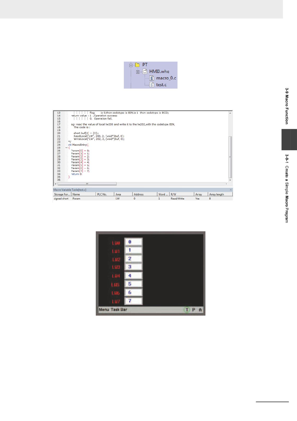
3 Functions of NB-Designer
Macro Optimization
Create the new Macro with the optional name (test.c). A brief provides of the Macro using the array
variables. The array variables can be defined only for the one-dimensional array.
For example:
Create one array variable with the length of 8. The definition of variable is shown as below.
3
(1) Place 8 Number Display components LW0 to LW7 with the consecutive addresses in Frame 0, and
make the timer to execute “test.c”.
(2) Perform the test, and the values displayed in Number Display components are same as the values
assigned in the Macro.
NB-series Programmable Terminals NB-Designer Operation Manual(V106)
3-271
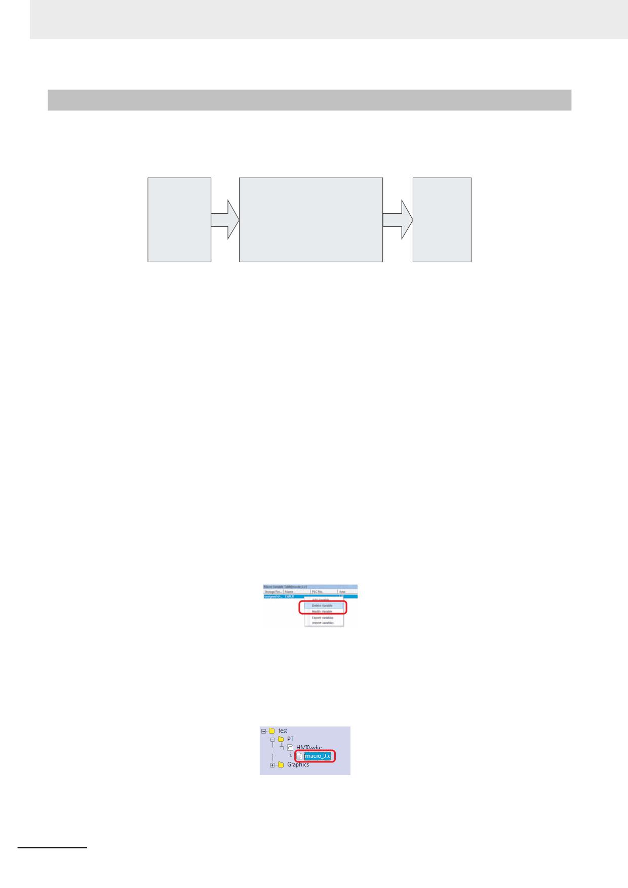
3 Functions of NB-Designer
3-9-2
Macro and Specification of Operation with Read/Write Variables
In this part, we will provide the description about specification of the operating Macro, and we will also
provide the description that should be noted when you use Macro.
The Macro can be regarded as a black box for input and output. Taking the example of the division
program which was mentioned in the first part of this section, the flow of the procession is as follows:
Macro
Read variable
int MacroEntry()
Write variable
(Read only)
{
(Write only)
LW0_R
If(LW1_R!=0)
LW2_W
LW1_R
LW2_W=(double)(LW0_R)/LW1_R,
Return 0;
}
The specification of the operation is as follows: Before the program is executed, the value from the
memory for LW0 and LW1 will be assigned to Read variables LW0_R and LW1_R, then Macro will be
executed. Later, after Macro function returns, the value of variable LW2_W will be written into LW2.
Therefore, the variables of the Macro performs like the copy of the memory and even if the variables
are modified, the value of the memory is not be changed.
Note 1
Since the read variables do not read the memory value during executing the Macro, the read value remain
the same as the one when the Macro read during operating. Even if the memory value is modified from the
external device during the Macro executing, result of the operation is not be affected.
2
Even if the memory value is written with a value from the external device during the Macro executing, the
memory value will be updated to the result of the execution of the Macro after the Macro completed.
3
The read variable is read only and the write value is write only. Therefore, writing the value to the read vari-
able or reading the writing variable by using the Macro are not impossible. Similarly, when one address is
used for reading and writing at the same time, use two different names by contrast for the variables such
as LW0_R and LW0_W for LW0.
4
The global variables or the static variables are not available in the Macro. If the data should be retained
using the global variables, use the PT internal memories such as LW or LB.
5
The values which output the result of the Macro should be prepared.
The description of the other functions are provided as follows.
(a) Modify or delete the variable in Macro.
Open the [Project File Window] and double-click the Macro file corresponded to open the [Macro
Variables Table] dialog box. Right-click the variable to select [Delete variable] or [Modify Variable].
Right-click the variable
to select [Delete variable]
or [Modify Variable]
Please be careful because the deleted variables can’t be restored.
(b) Delete the whole Macro file.
Open the Project File Window, press “Delete” key after selecting the corresponding Macro file.
Select and press
“Delete” key.
Please be careful because the deleted Macro files can’t be restored.
3-272
NB-series Programmable Terminals NB-Designer Operation Manual(V106)
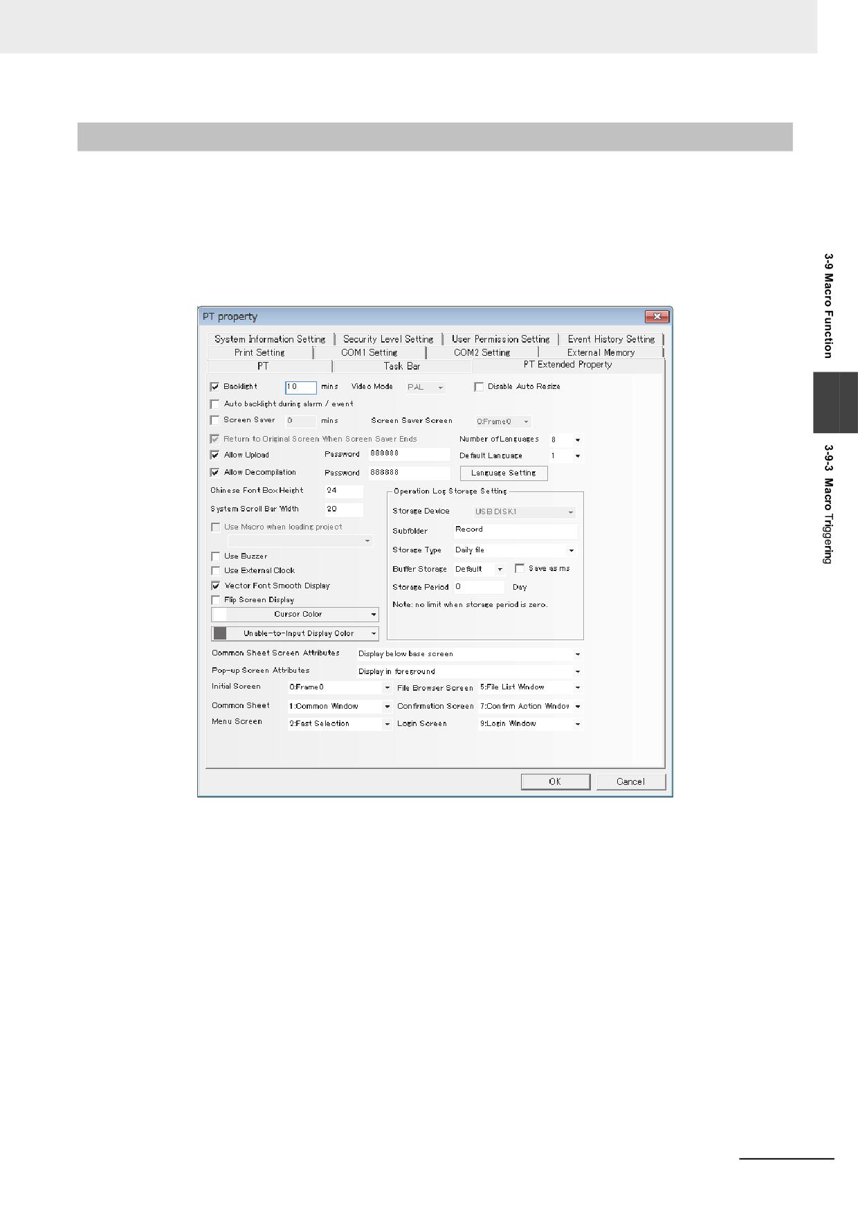
3 Functions of NB-Designer
3-9-3
Macro Triggering
There are many flexible methods for triggering Macro. Using the triggering methods for Macro flexibly
can realize more flexible and powerful functions conveniently.
NB-Designer currently supports the following methods for triggering Macro:
1
Macro when loading project
Check the “Use Macro when loading project” check box in the “PT Extended Properties” tab.
3
2
Function Key
Using “Execute Macro” function of Function Key to trigger the Macro is a kind of common
triggering method.
3
Timer
Executing the [Execute Macro] function by the Timer function allows the combination of the
Macro and the Timer function.
NB-series Programmable Terminals NB-Designer Operation Manual(V106)
3-273