NB-series Programmable Terminals. NB-Designer OPERATION MANUAL (2026) - page 2
3 Functions of NB-Designer
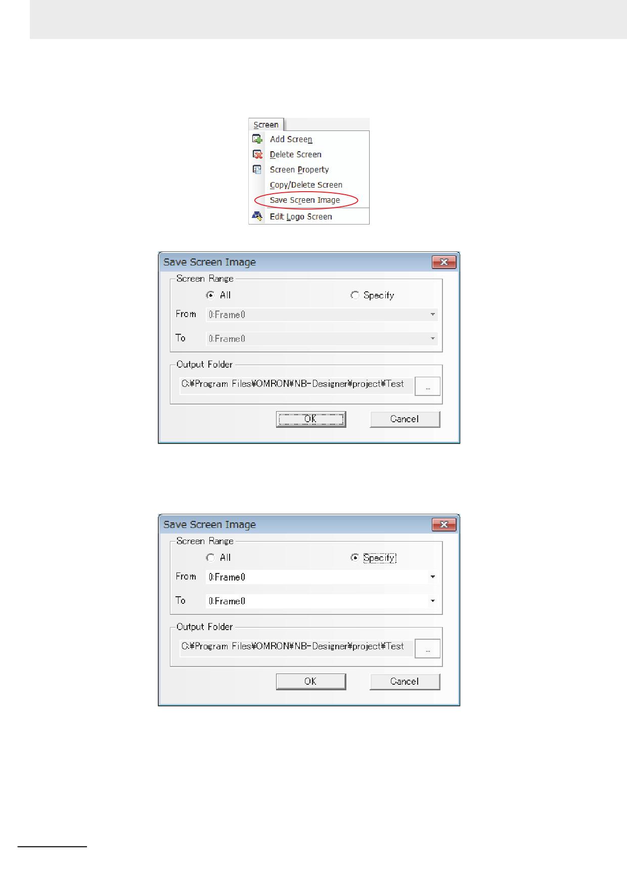
Save Screen Image
Select a project data and open a screen to enable this function.
Click [Screen] - [Save Screen Image] , then the dialog box below appears to save the screen images.
Screen Range
Specify the screen area to save to a file. Select [All] to save all screens. Click [Specify], then the field
[From] and [To] are enabled. Specify the range to save.
Output Folder
Designate a folder to save the file. The folder where the project data is stored is specified by default.
A screen image data is saved as bitmap file to the designated folder.
3-30
NB-series Programmable Terminals NB-Designer Operation Manual(V106)
3 Functions of NB-Designer
3-2-5
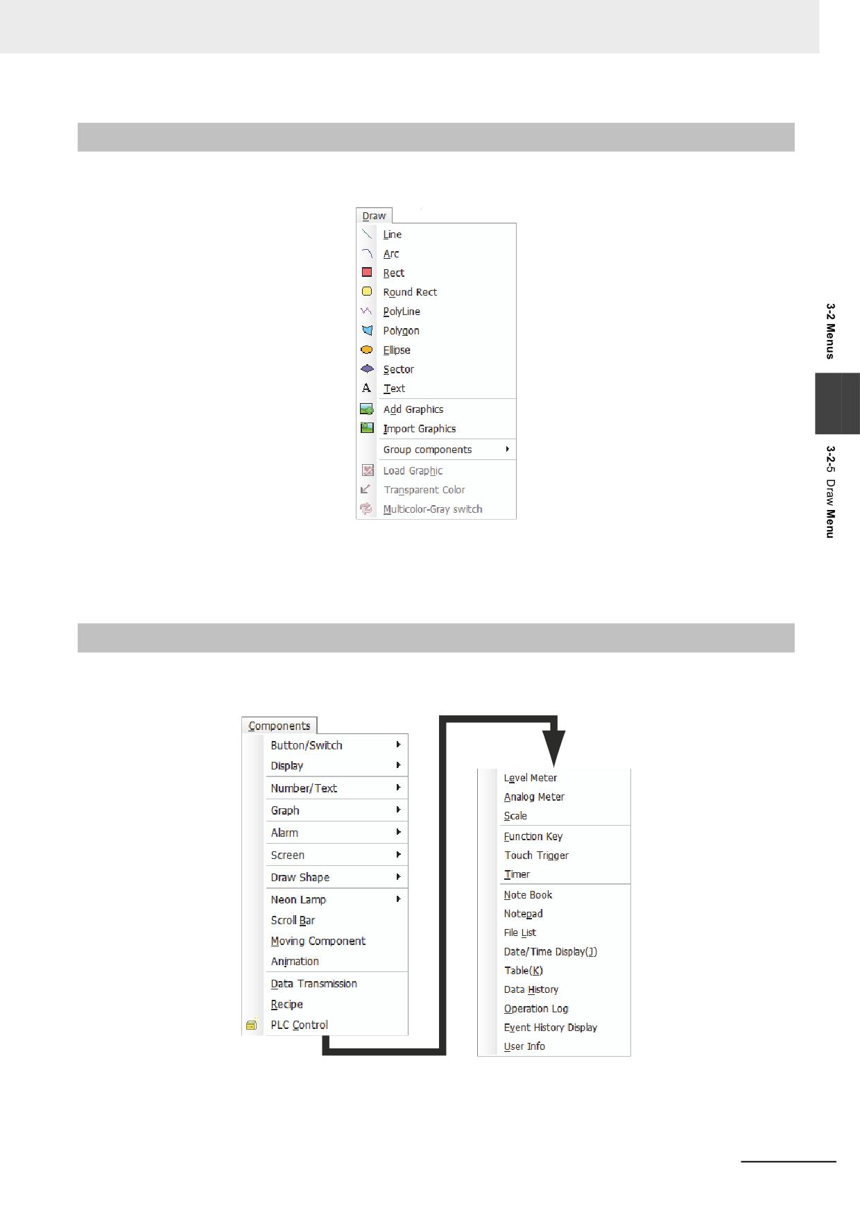
Draw Menu
The corresponding contents in the [Draw] menu shown as below have been described in 3-2-3 View
Menu (Page 3-16).
3
Some NB models display a screen close to the frame of a front sheet. When placing texts or figures at
the edges of the screen (top, bottom, left, right), please be aware that there might be slight differences
in appearance between on NB-Designer and an actual NB unit.
3-2-6
Components Menu
For the corresponding contents in the [Components] menu shown as below, refer to 3-6 Parts (Page 3-
82), 3-7 Function Parts (Page 3-200) and 3-8 Project Database (Page 3-238).
NB-series Programmable Terminals NB-Designer Operation Manual(V106)
3-31
3 Functions of NB-Designer
3-2-7
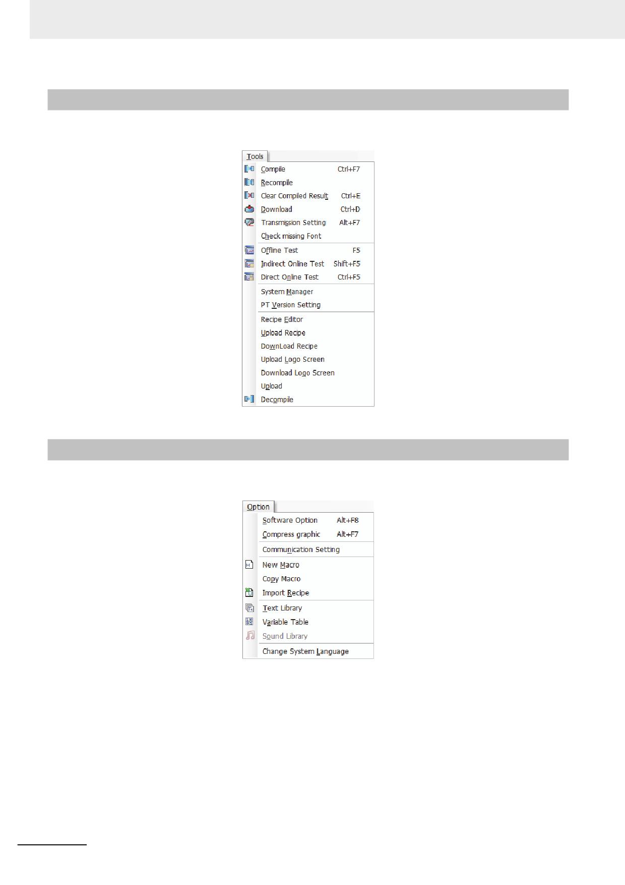
Tools Menu
For the corresponding contents in the [Tools] menu shown as below, refer to 3-12 Recipe Data (Page 3-
342), 3-14 Test (Page 3-359) and 3-15 Download (Page 3-362).
3-2-8
Option Menu
The corresponding contents in [Option] menu shown as below have been described in 3-2-3 View
Menu (Page 3-16).
3-32
NB-series Programmable Terminals NB-Designer Operation Manual(V106)
3 Functions of NB-Designer
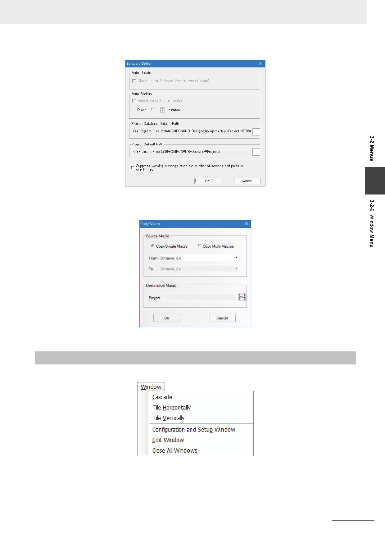
Software option: Sets operation of NB-Designer.
3
Copy Macro: Macros can be copied and pasted to other project. Copied macros are pasted to the
destination project given the macro numbers which begin with the next number of the last macro
number.
Change System Language: used for changing the system language of the software tool.
3-2-9
Window Menu
The corresponding contents in the [Window] menu are as follows.
NB-series Programmable Terminals NB-Designer Operation Manual(V106)
3-33
3 Functions of NB-Designer
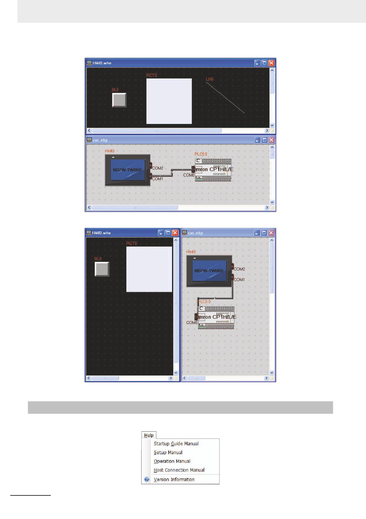
The horizontally-tile window is shown as below.
The vertically-tile window is shown as below.
3-2-10
Help Menu
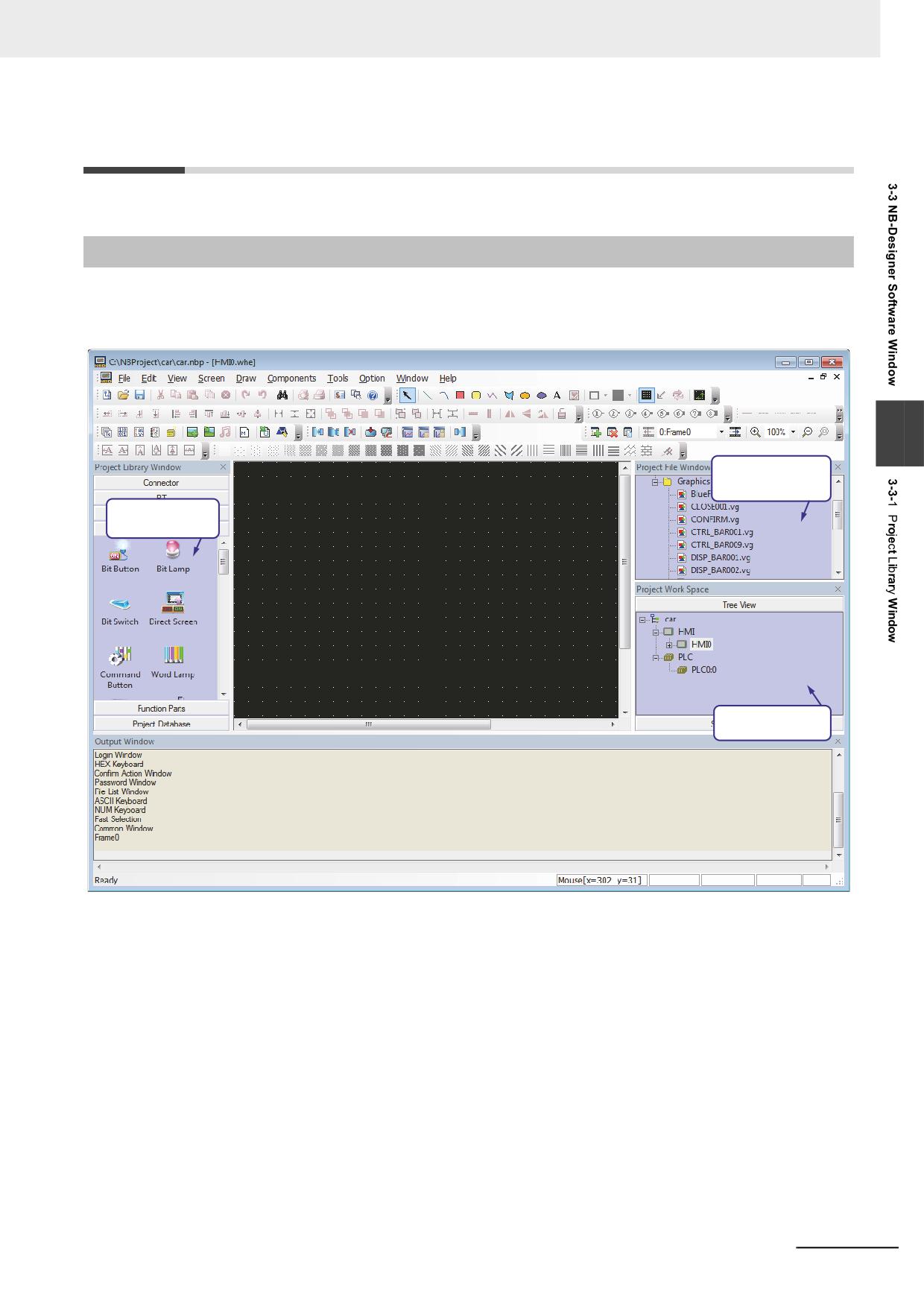
The corresponding items in the [Help] menu are shown as follows.
3-34
NB-series Programmable Terminals NB-Designer Operation Manual(V106)
3 Functions of NB-Designer
3-3
NB-Designer Software Window
NB-Designer has quite a few windows, which will be illustrated in this part.
3-3-1
Project Library Window
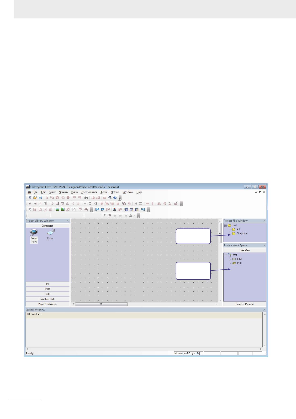
When starting the NB-Designer, you will see Project Library Window, Project File Window, and Project
Work Space shown as below. For the concept of the “screen”, the brief will be provided in 3-4 Screen
Concept (Page 3-47).
3
Project File Window
Project Library Window
Project Work Space
The Project Library Window contains: Connector, PT, PLC, Parts, Function Parts and Project Database.
Connector: Serial Port, Ethernet
PT: NB3Q-TW00B(-V1), NB3Q-TW01B(-V1), NB5Q-TW00B(-V1), NB5Q-TW01B(-V1)...
PLC: OMRON, SIEMENS, MITSUBISHI, Schneider…
Parts: Bit Button, Bit Switch, Word Lamp, Data Log, XY Graph, Number Input, Text Input…
Function Parts: Scale, Function Key, Alarm Display, Timer…
Project Database: Text Library, Variable Table, PLC Control…
NB-series Programmable Terminals NB-Designer Operation Manual(V106)
3-35
3 Functions of NB-Designer
Directions:
1
Connector
Just click “Serial Port”, and drag it to the Project Work Space.
2
PT
Check your PT type, find and drag the PT with the same type in the “PT” to the Project Work
Space.
3
PLC
Check your PLC type, find and drag the PLC with the same type in the “PLC” to the Project
Work Space.
After finishing selection of the PLC, PT and Connector, carry out connection. The connection
method is as follows: move the locations of PT and PLC accordingly, or click one end of the
connection line and drag it to the vicinity of the COM port of the PLC or the PT, then bring the
connection port close to either end of the connection line, and a successful connection can be
completed.
Note If the PLC or PT is not dragged into the “Project Work Space”, both of the “Project File Window” and “Project
Work Space” will be empty, as shown below.
PT and Graphics
are empty
PT and PLC
is empty
3-36
NB-series Programmable Terminals NB-Designer Operation Manual(V106)
3 Functions of NB-Designer
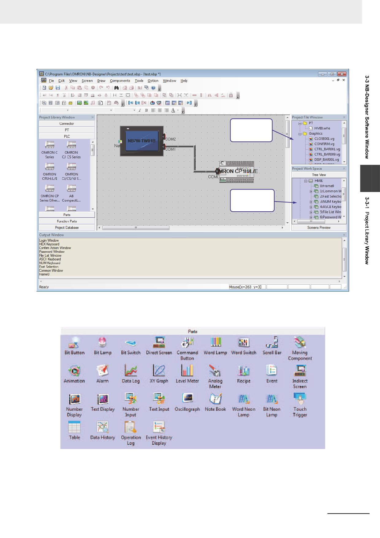
Once the PLC and PT are dragged in, the “Project File Window” and “Project Work Space” will
be filled with appropriate content, as shown below:
PT with appropriate
contents
3
PT and PLC with
appropriate contents
4
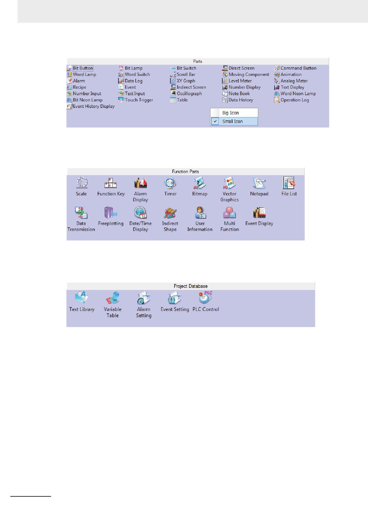
Parts
These include various editing components, as shown below:
When a project is created, and the Edit Window is entered, it just needs to drag the required
components to the Edit Window.
As to the usage methods of the components, refer to 3-6 Parts (Page 3-82).
NB-series Programmable Terminals NB-Designer Operation Manual(V106)
3-37
3 Functions of NB-Designer
In the Project Library Window, you can right-click, select and use “Small Icon”, as shown below.
5
Function Parts
These include Scale, Function Key, Alarm Display, Timer, etc. For details, refer to 3-7 Function
Parts (Page 3-200).
6
Project Database
This contains Text Library, Variable Table, Alarm Information, Event Information and PLC
Control. For details, refer to 3-8 Project Database (Page 3-238).
3-38
NB-series Programmable Terminals NB-Designer Operation Manual(V106)
3 Functions of NB-Designer
3-3-2
Project File Window
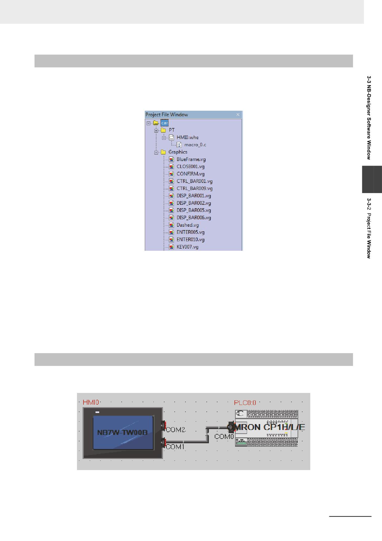
The Project File Window is intended for displaying information about the PT, Macro, Recipe and Vector
Graphic, etc. contained in a project. If this project uses 1 PT, only one “HMI0.whe” will appear below the
[PT]. if 3 PTs are involved, “HMI0.whe, HMI1.whe, HMI2.whe” will appear accordingly. The rest can be
deducted from this. See the following diagram.
3
By clicking the “+” or “-” symbol on the left of the icon, the folder tree can be unfolded or folded.
By double-clicking a specific file, the editing state can be entered.
Note The recipe file (.RCP) can only be imported and deleted, but not be edited in the Edit Window.
Graphics
The Graphics mainly indicates this project contains how many Vector Graphics and bitmaps. If a new
Vector Graphics or bitmap is created in this project, it will show up immediately here. If a created Vector
Graphics or bitmap is double-clicked, the screen will be switched to the graphics edit window
immediately. For Vector Graphics and bitmaps, refer to 3-5-5 Vector Graphic (Page 3-60) and 3-5-6
Bitmap (Page 3-65).
3-3-3
Project Work Space
The Project Work Space is mainly intended for displaying the structure of the project, and contains two
parts: PT and PLC, as shown below.
NB-series Programmable Terminals NB-Designer Operation Manual(V106)
3-39
3 Functions of NB-Designer
And the schematic diagram is shown as below.
Part 0
Project Name
Screen 0
Part 1
HMI
HMI 0
Screen 1
Part n
PLC 0
Screen n
PLC
PLC 1
PLC n
PT
It mainly displays (stores) the PT used in the project, each of which also has a subfolder. Every
folder stores its own structure.
PLC
It mainly displays (stores) the number of PLC, PLC No. and Station No. addresses used in the
project.
Note Creating a new project for each PT is recommended.
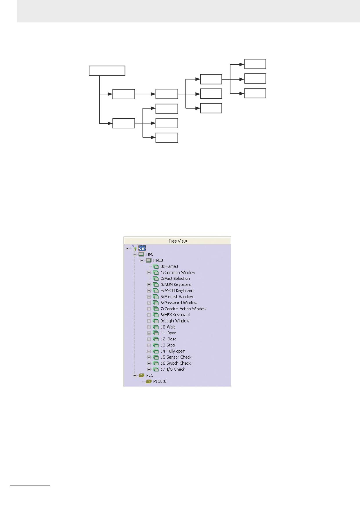
Tree View
All the components contained in each screen will be displayed here, and if there is no component in
a screen, nothing will appear below it.
By clicking the “+” or “-” symbol on the left of icon, the folder tree can be unfolded or folded. Directly
double-click the Screen or the component No. in the Screen to skip to the edit page involving the
component. When a Screen or component is selected, pressing the DELETE button can delete the
related screen or component.
3-40
NB-series Programmable Terminals NB-Designer Operation Manual(V106)
3 Functions of NB-Designer
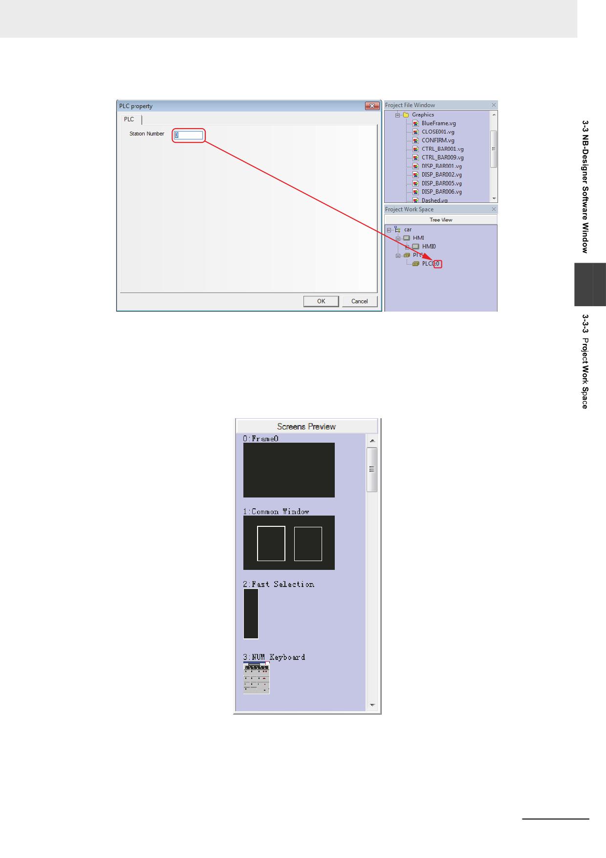
Explanation about the characters on the top of the PLC Property window.
3
The first digit indicates the PLC No. currently used.
The second digit indicates the Station No. of PLC currently used.
Screens Preview
Click [Screens Preview] in the [Project Work Space] to display the preview of the corresponding
screen. This makes browsing the thumbnails quite conveniently.
PLC and PT replacement
• Supporting PLC Model Replacement
Note PLC replacement must be carried out through the [Change PLC Model] option. If you do not use this
function and delete all the settings of PLC to reconnect with the new PLC, the PLC area is replaced with
all the local addresses of PT.
NB-series Programmable Terminals NB-Designer Operation Manual(V106)
3-41
3 Functions of NB-Designer
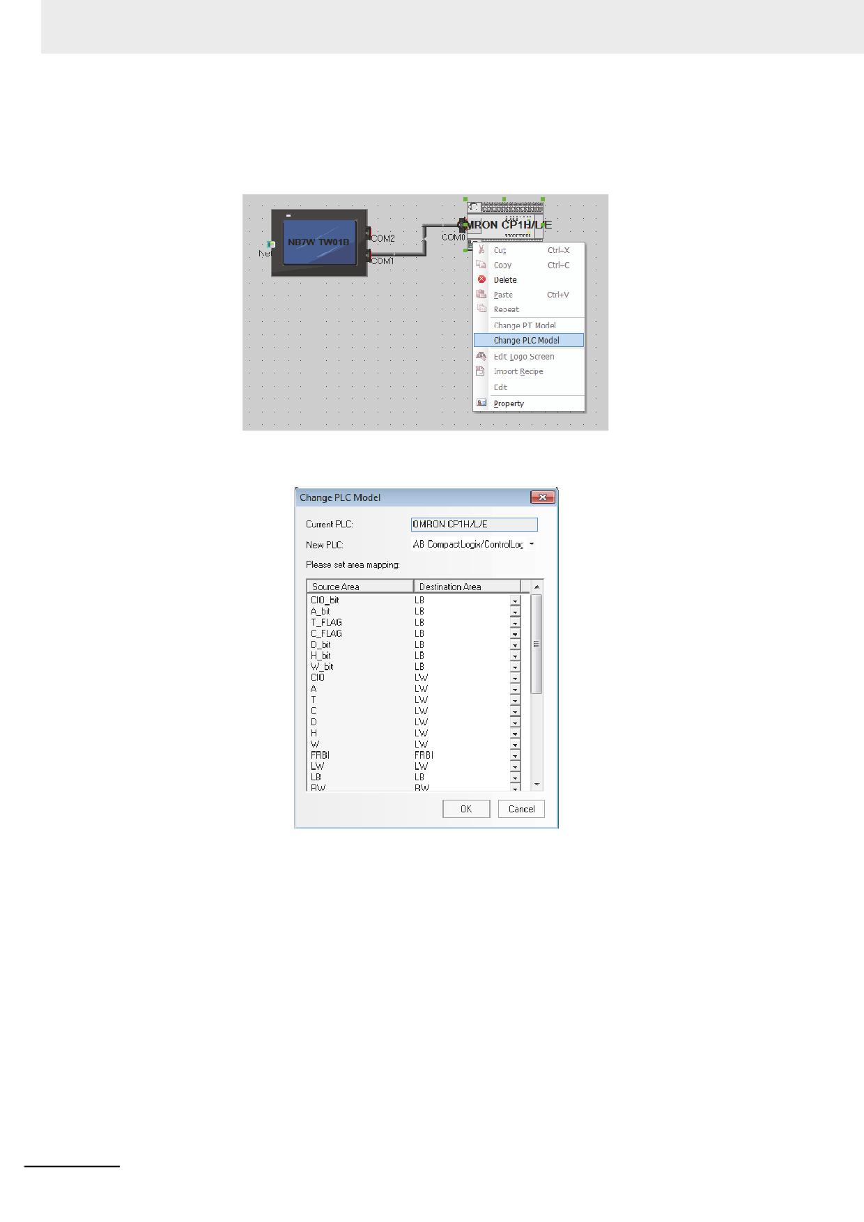
It provides a parameter setting dialog box for the PLC to be replaced and other PLCs in the
navigation mode for the user to make replacement operation. Select a PLC and right-click it in the
Configuration and Setup Window to make the pull-down menu popup, and then click “Change PLC
Model”.
Then, the Change PLC Model dialog box will pop up, as shown below.
A dialog box as shown above will pop up automatically, and all the supported PLC names are
included in the pull-down list of the PLC names. When the user select a PLC, the memory address
types supported by this PLC will be added to the address type box. The default selections are LB &
LW, but the user can select different address types according to the specific PLC. After being
confirmed by the user, the PLC will be replaced, and the corresponding PLC memory address in the
project will also be replaced at the same time.
Note Unit replacement between units employing Ethernet connection and serial connection is impossible.
3-42
NB-series Programmable Terminals NB-Designer Operation Manual(V106)
3 Functions of NB-Designer
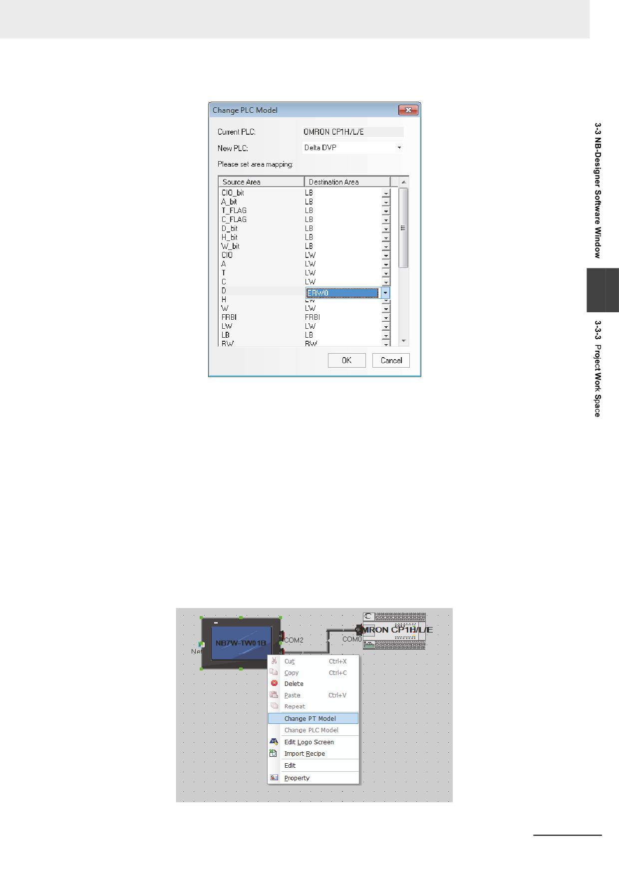
An example of setting addresses for [Current PLC] and [New PLC] are as follows.
3
• Supporting PT Model Replacement
Note 1
PT replacement must be carried out through the [Change PT Model] option. If you do not use this
function and delete all the settings of PLC to reconnect with the new PLC, the PLC area is replaced
with all the local addresses of PT.
2
NB-TWB can be replaced with NB-TWB-V1.
NB-TWB-V1 cannot be replaced with NB-TWB.
3
NB-TWB-V1 does not support the creation of projects containing multiple PTs. Therefore,
NB-TWB projects that include multiple PTs cannot be replaced with NB-TWB-V1.
4
NB-TWB and NB-TWB-V1 support different PLC models. Therefore, projects that
include PLC models not supported by NB-TWB-V1 cannot be changed to NB-TWB-
V1. Refer to A-5 Lists for Supported OMRON PLC (Page A-17) for the types of OMRON PLCs com-
patible with the NB Series. Refer to the NB-series Programmable Terminals Host Connection Manual
(Cat. No. V108) for the types of third-party PLCs compatible with the NB Series.
When the PT needs to be replaced, you can select the PT by right-clicking it in the Configuration
and Setup Window, and select “Change PT Model” in the pop-up menu.
NB-series Programmable Terminals NB-Designer Operation Manual(V106)
3-43
3 Functions of NB-Designer
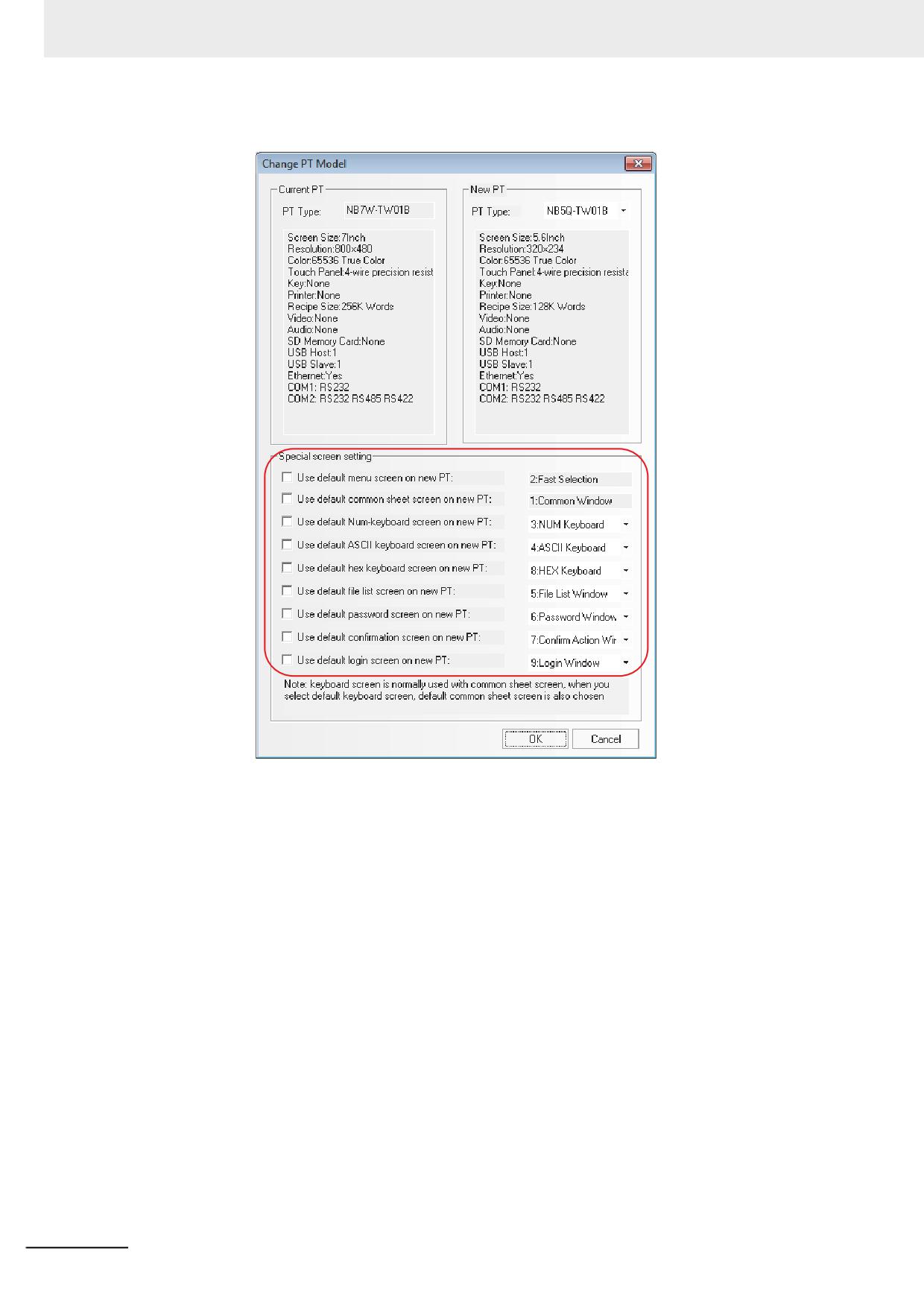
The following dialog box will pop up automatically.
Here, the name and descriptions of the Current PT cannot be altered, while the pull-down box of the
New PT lists all the supported [PT type], and the descriptions displayed at the lower part will be
updated automatically according to the type selected by the user. After being confirmed, the PT will be
replaced, and all the size of graphics in the PT will zoom automatically according to the resolution of the
screen.
After the PT is replaced, the original user edit screen will be adjusted by related scales according to the
difference of the resolution of various types. All the components with screen display will adjust
automatically. For example, all the components (such as the bitmaps, Vector Graphics, button and
lamp, etc.) with location and size adjustments can all change their sizes automatically. However, note
that there are a few exceptions: as the font size of text strings and label can’t be changed, the
components using text strings and label will be restricted to mainly display the text in the minimum
display area when size changes, especially when it becomes smaller as square components like the
Analog Meter change sizes in a “square” way, the changed sizes may disrupt the proportion among the
component sizes, therefore it requires a second fine-adjustment by the user.
By the [Special screen settings] in the dialog box, the special screen which will be replaced to Replace
PT is set. If the [Special screen settings] is not used, the special screen of the Current PT will continue
to be used.
If the resolutions of the Current PT and New PT are the same, no adjustment is required. But on the
contrary, if they are different, it will require the user to adjust the fonts and pictures to appropriate sizes.
3-44
NB-series Programmable Terminals NB-Designer Operation Manual(V106)
3 Functions of NB-Designer
3-3-4
Output Window
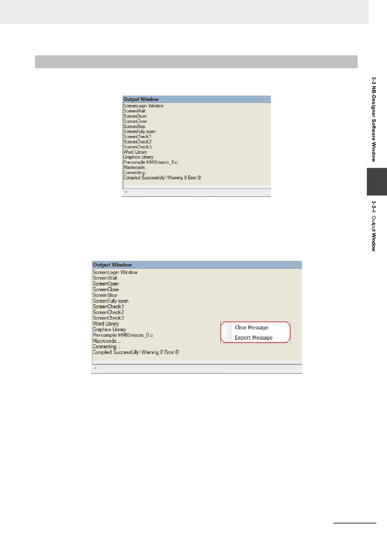
The Output Window mainly displays compilation information of the project so that the user can precisely
pinpoint where errors lie, as shown below.
3
When the project is opened, the Output Window will display the loaded information of the project. when
the project is compiled, the Output Window will display the compilation process and error information.
Clearance/Export of Message
The compiled information can be cleared or exported in the Output Window. Right-click the mouse in
the [Output Window], the following menu will pop up.
Clear Message: All the information in the Output Window will be removed.
Export Message: All the contents in the Output Window are exported to the folder which contains the
current project, forming a file named “log.txt”.
NB-series Programmable Terminals NB-Designer Operation Manual(V106)
3-45
3 Functions of NB-Designer
3-3-5
Component List Window
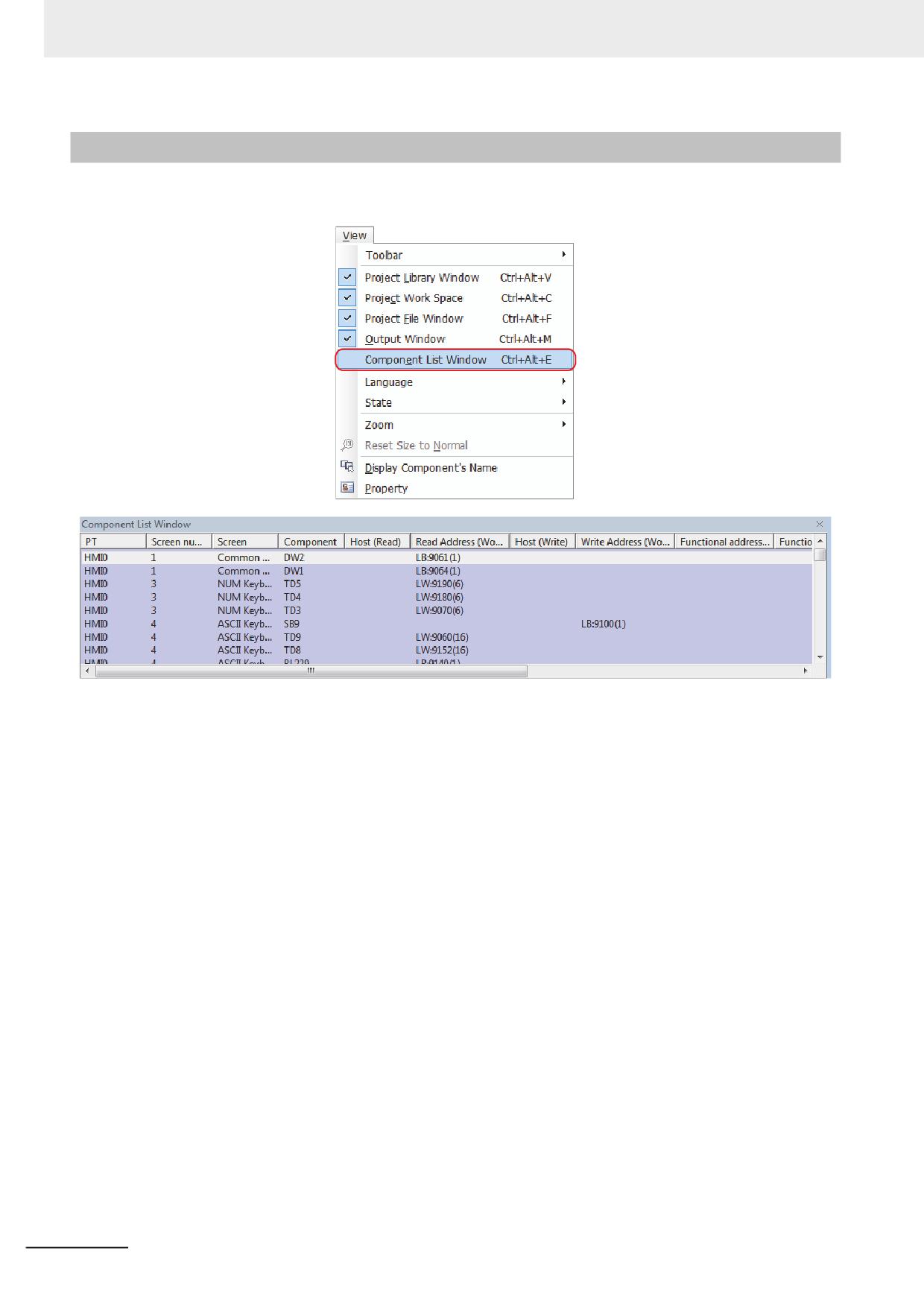
If the [Component List Window] is selected from the [View] menu, the Component list window will pop
up.
This window displays all the component information used by the project, including PT No., Screen,
Component's Name, Read PLC, Read Address, Write Address, Functional Address etc. Double-click
an item to reveal the Properties of the selected component, and the Edit Window will skip to the screen
where this component locates.
3-46
NB-series Programmable Terminals NB-Designer Operation Manual(V106)
3 Functions of NB-Designer
3-4
Screen Concept
3-4-1
Screen Types
The project of the NB-Designer is composed of multiple screens. There are 3 types of screen, i.e. Base
Screen, Common Sheet and Menu Screen. The Base Screen after its size is changed can also be used
as Pop-up Screen. All the screen can be used as the Sheet Screen.
Base Screen
This is the common-type screen. When Base Screen is switched by using “Screen switching”
command, the current screen will be cleared (All the screen rather than Common Sheet and Menu
Screen will be cleared.), and Base Screen to be switched to will be displayed in the current screen.
When the component in Base Screen calls the pop-up screens out, the original information in Base
3
Screen will be reserved, and the called pop-up screen will be attached to the current Base Screen.
The master-slave relationship is between Base Screen and all of related pop-up screens. When
Base Screen N is switched to Base Screen M, all of the sub-screens of Base Screen N will be
closed while Base Screen M and its sub-screens will be displayed. Base Screen must cover the
whole screen.
Menu Screen
Menu Screen is the screen called by pressing the button of Menu Screen while the task-bar is
displayed, and it will be always displayed in the screen until the operation button makes it hidden.
Therefore, it can be used to put screen-switching button or some other common components. The
default Menu Screen is Frame 2. When the other screen is set as Menu Screen, the size of that
screen must be same as that of Menu Screen.
Common Sheet
Common Sheet will always be displayed in the screen, and the components to be displayed forever
can be put in Common Sheet. In this way, you can see the state of this component or operate this
component at any time. The default Common Sheet is Frame 1. You can use [Change Common
Sheet] function key to switch the other screen as the current Common Sheet, but only one screen
can be used as the current Common Sheet.
Sheet Screen
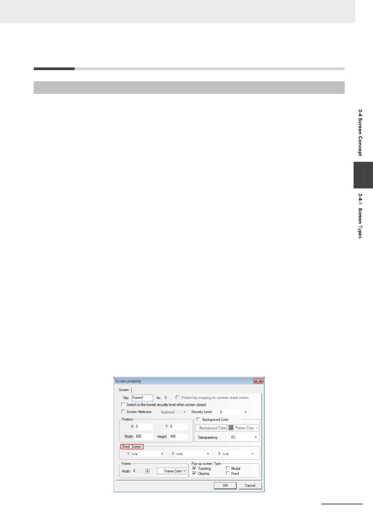
3 Sheet Screens (max.) can be set for the screen in [Screen Property] dialog box. Sheet Screen is
generally used to put some common components such as backg1round graphics, charts and titles
and so on for the multiple components. Each screen can be set as Sheet Screen.
NB-series Programmable Terminals NB-Designer Operation Manual(V106)
3-47
3 Functions of NB-Designer
As shown above, Sheet Screen can be selected directly from the [Sheet Screen] option. Sheet
Screen is different from the general screen. The components in Sheet Screen will be inserted into
the general screen during the running, and in fact Sheet Screen isn’t displayed at all, but the display
and control of its components are similar to that of the components in the general screen.
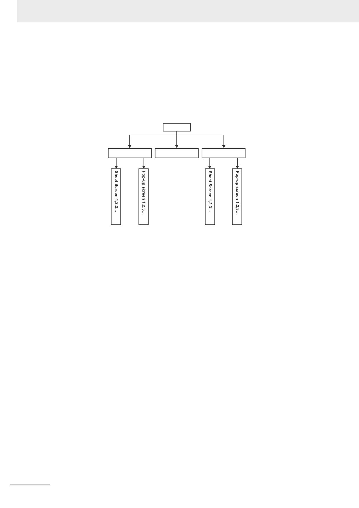
The Relationship of Screen
One screen can include Common Sheet, Base Screen and Menu Screen while one Common Sheet
or Base Screen can include many pop-up screens. And the relationship between them is shown as
below.
Screen
Base Screen
Menu Screen
Common Sheet
When the screen-switching command is executed, the PT will clear the current screen (the pop-up
screen attached on the current screen etc included) and switch to the screen to be displayed, but
Common Sheet will always be displayed in the screen. The original contents of Base Screen can’t
be changed by the pop-up screen that called by the direct screen or indirect screen, and the pop-up
screen is just attached to Base Screen. In addition, up to 3 sheet screens can be set for each screen
in screen property setup.
When one Base Screen (Screen No. is 0 or ranges from 10 to 32767) is called out, all the
components in this screen will be displayed in the PT. If Base Screen has the Sheet Screen, all the
components defined in its Sheet Screen will be displayed. All of the Touch Trigger components
(such as Bit Button, Function Key etc.) defined in the Sheet Screen are valid in the current screen. If
there are display components in Common Sheet, they will be displayed in the current screen. And all
the Touch Trigger components defined in Common Sheet are valid.
Each project includes 32768 screens (max.) (Base Screen, Common Sheet and Menu Screen etc
included), and only one screen can be used as Menu Screen. But you can use [Change Menu
Screen] function key to make the screen switch to the specified screen as Menu Screen. For details,
refer to 3-7-2 Function Key (Page 3-201).
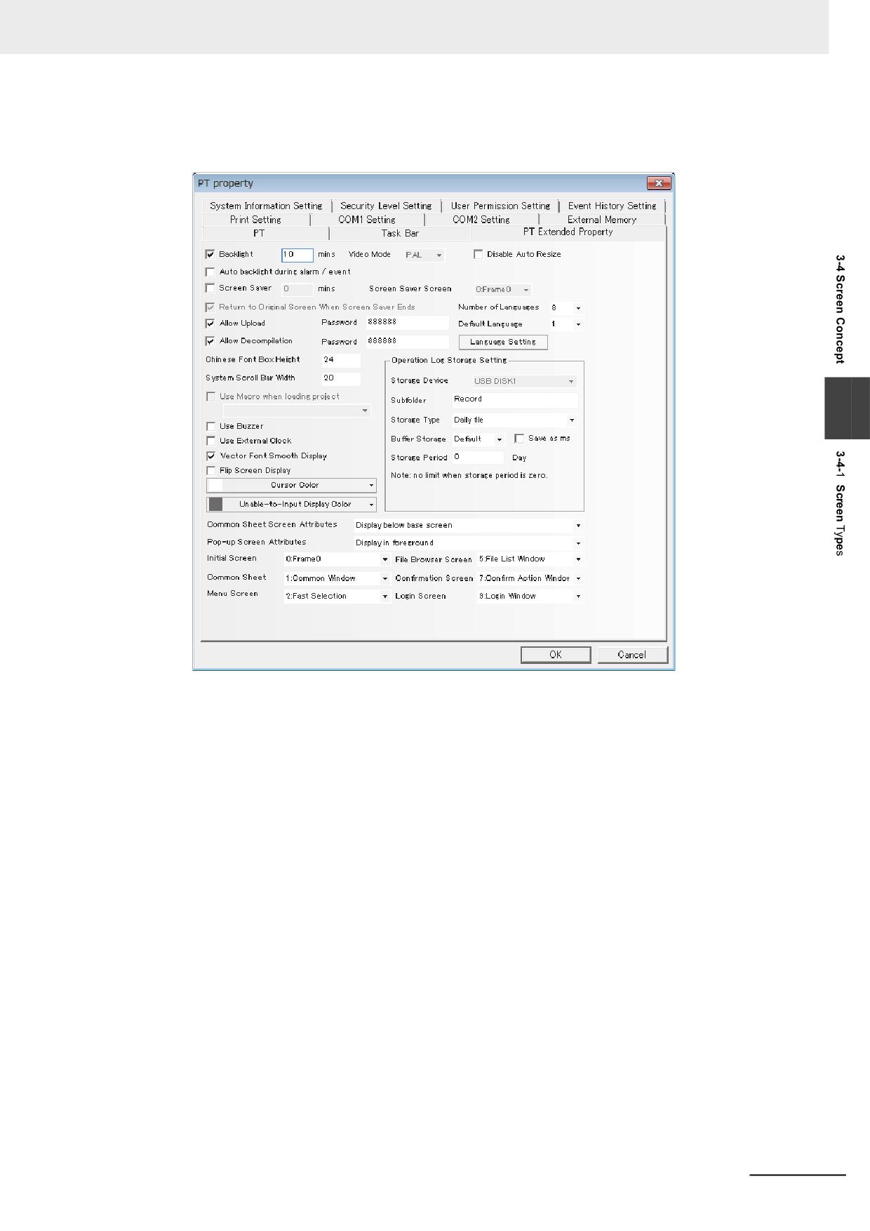
Each new project has a default initial screen, and the default screen No. is 0 (If you want to change
it, you just need to make changes in [PT Property] in project editing screen.). The valid screen No.
ranges from 0 to 32767.
3-48
NB-series Programmable Terminals NB-Designer Operation Manual(V106)
3 Functions of NB-Designer
The default Common Sheet and Menu Screen for the project are Frame 1 and Frame 2. If you want to
change the default Menu Screen and Common Sheet, you just need to double click PT to modify [PT
Extended Property], as shown below:
3
Note 1
16 pop-up screens can be opened simultaneously.
2
If you call two or more of the same screen simultaneously from one screen, the display and notifications
may not work correctly. The following operations are prohibited: opening two same screens on the base
screen using Direct Screen or Indirect Screen, and setting the base screen and common sheet on the
same screen.
3
The screens closed by the function keys can’t close the Direct Screen or Indirect Screen, because the
opening or closing of Direct Screen is related to the ON/OFF status of bit address that controls the Direct
Screen, while the opening and closing of Indirect Screen is just related to the data content of the word
address that controls the Indirect screen. The screen closed by the function keys can’t change the values
of these bits (words) addresses, so it can’t close these screens mentioned above.
4
All the Pop-up Screens are attached to the current Base Screen, so when the current screen is closed (or
switched to the other Base Screen), the attached Pop-up Screen will be closed. In this case, if the screen
is switched back to this Base Screen, you will find that the Pop-up Screens originally attached to this Base
Screen still exist (Otherwise there are commands sent to close them.)
5
Base Screen must cover the whole screen.
6
Every Pop-up Screen belongs to the screen where the component ejecting them locates, and master-
slave relationship is between them. Therefore, the screen opened by the component in Common Sheet
will always be displayed until Common Sheet closes it again.
NB-series Programmable Terminals NB-Designer Operation Manual(V106)
3-49
3 Functions of NB-Designer
3-4-2
Screen Property
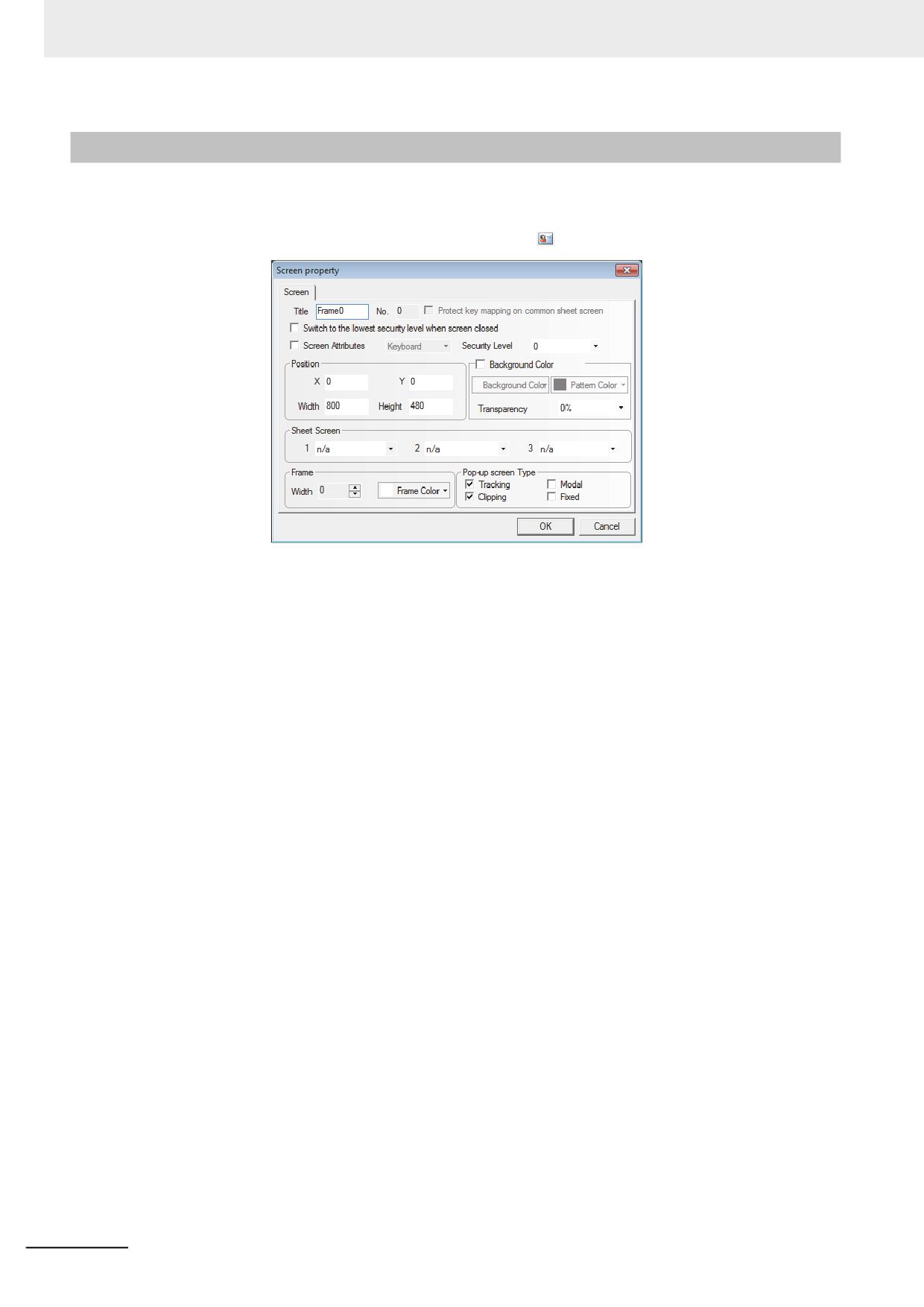
The methods to change the screen property:
• Double-click the area in which no components are arranged in the screen.
• Do not click the components in the screen and click the
icons of tool bar.
Title
Assign the unique name for each screen for convenient differentiation. Of course, the screen title
can be changed.
Screen No.
Screen No. range is from 0 to 32767. When a new screen is created, automatically is assigned a
Screen No.
Screens from 0 to 10 are fixed. The screen No. of the other screens can be changed by the user.
Screen No. can be not consecutive.
Position
When the screen is the screen ejected by using “Pop-up Screen” function of the function key, the
vertex in the upper-left of the screen will be displayed in this position.
Width and Height
Width and height can be set for the Pop-up Screen, and if it is the Base Screen, it must be set to the
default size (i.e. the size of the full screen).
Screen Attribute
Keyboard page determines whether to set the screen as Keyboard Screen. Print page can be used
to set the size of this screen regardless of the limitation of the actual resolution of the PT. The NB
Series does not support [Print page].
Protect key mapping on common sheet screen
The NB Series does not support this function.
Switching to the lowest security level when screen closed
If the security level is set for one screen to realize the function, i.e. the password will be cleared
automatically when the screen is closed, and the password needs to be input again when the screen
is entered again, the security level will become 0 only if the screen is closed.
3-50
NB-series Programmable Terminals NB-Designer Operation Manual(V106)
3 Functions of NB-Designer
Background Color
If the filling effects for the screen are needed, select this option.
Pattern Color and Background Color
The selected [Pattern Color] is applied as outline color and the selected [Background Color] is
applied as ground color. (For details, refer to the descriptions of “Fill Style Toolbar” in 3-2-3 View
Menu (Page 3-16)). In the default settings, the [Pattern style] is set to 0 so that only the backg1round
color is displayed by this setting.
Pop-up Screen Type
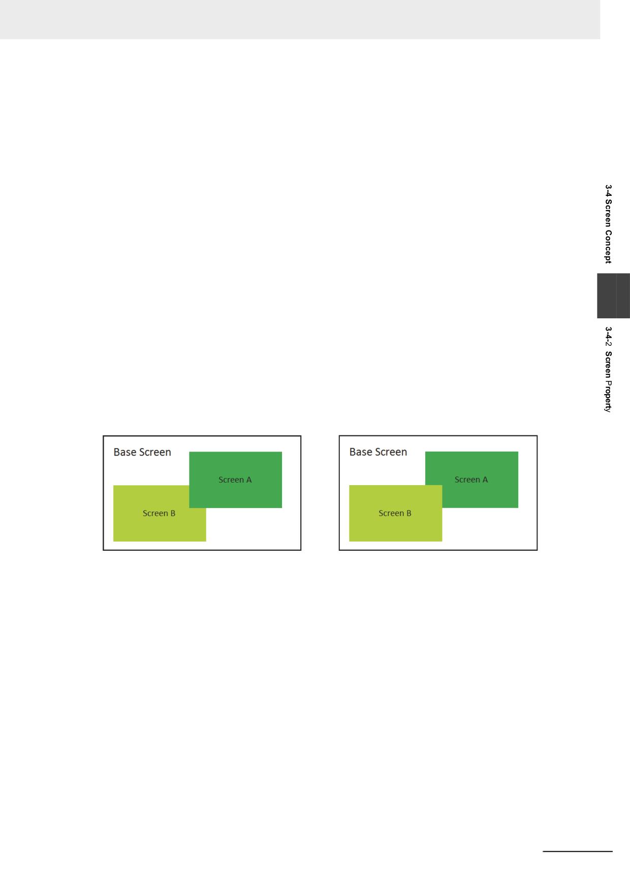
The types are “Tracking”, “Modal”, “Clipping” and “Fixed”.
The above parameters show the relationship between one Pop-up Screen and its adjacent screen. If
one Pop-up Screen features “Modal”, the location of parent screen will be frozen after it pops up,
and the pop-up screen will always be displayed in the Top layer. If one Pop-up Screen features
3
“Clipping”, the border of this screen will be restricted by its parent screen, i.e. the part displayed out
of the border of its parent screen will be cut off. If one Pop-up Screen features “Tracking”, it will
move together when its parent screen moves.
Note If “Clipping” is selected, “Tracking” must be selected simultaneously.
The following Screen A and Screen B are both attached to the Base Screen. Generally, Screen A
will be displayed in the Top layer when it is touched. But if “Fixed” is selected for Screen A, it will not
be displayed in the Top layer even if it is touched, but it will always be attached to its parent screen.
Note The screen No. can’t be changed once it is created, but the name, frame and backg1round can be changed
still.
Security Level
Set the corresponding security level for the screen. For details, refer to 3-13 Security Level (Page 3-
353).
Sheet Screen
Set the corresponding Sheet Screens for the current screen. The screen to be set as the Sheet
Screen must be the created screen, where the components used by the multiple screens together
can be put.
Frame
Refers to the frame recommended to be used by the Pop-up Screen. The width of the frame can be
any number from 0 to 16. If the width is not 0, the color can be selected for the frame.
NB-series Programmable Terminals NB-Designer Operation Manual(V106)
3-51
3 Functions of NB-Designer
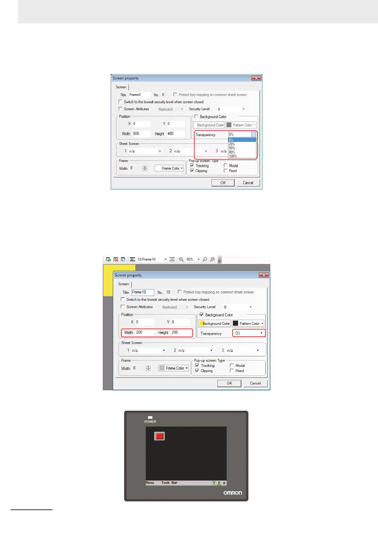
Transparency
It is only valid for the Pop-up Screen and the Menu Screen.
Example of transparency of Pop-up Screen
Placing one function key to [Pop-up screen] “Frame 10” with the property in “Frame 0”, as shown
below.
• When the transparency is 0%.
Set the width and height of Frame 10 to “200” each, the [Background color] to “Yellow”, and the
[Transparency] to “0%”, as shown below.
Perform the offline test, as shown below.
3-52
NB-series Programmable Terminals NB-Designer Operation Manual(V106)
3 Functions of NB-Designer
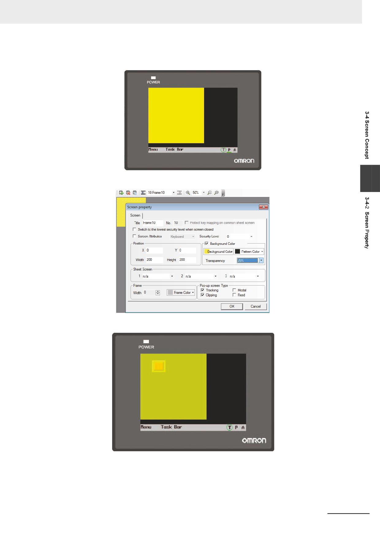
Press the function key and pop-up Frame 10 will cover the function key, which is caused by the
transparency of 0% for Frame 10, as shown below.
• When the transparency is 20%.
3
Perform the offline test and press the function key, the displayed effect is shown as below.
NB-series Programmable Terminals NB-Designer Operation Manual(V106)
3-53
3 Functions of NB-Designer
• When the transparency is 80%.
Perform the offline test and the effect is as shown below.
3-4-3
Screen Creation
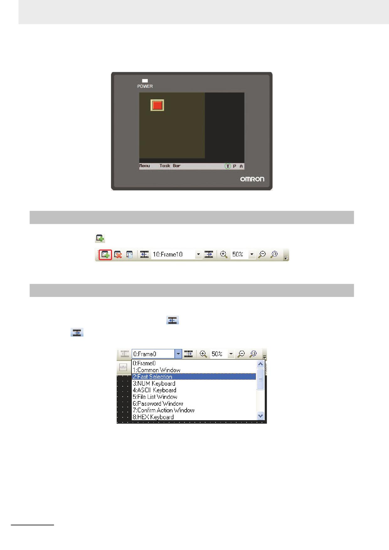
Clicking the
icon in [Screen Toolbar] can create a new screen.
3-4-4
Screen Opening
After the screen is created, the previous screen can be displayed by selecting it in the pull-down menu
in [Screen Toolbar] or by clicking the
icon, and the next screen can be displayed by clicking
the
icon. If the mouse with the roller is used, the screen No. can be changed directly by using the
roller.
3-54
NB-series Programmable Terminals NB-Designer Operation Manual(V106)
3 Functions of NB-Designer
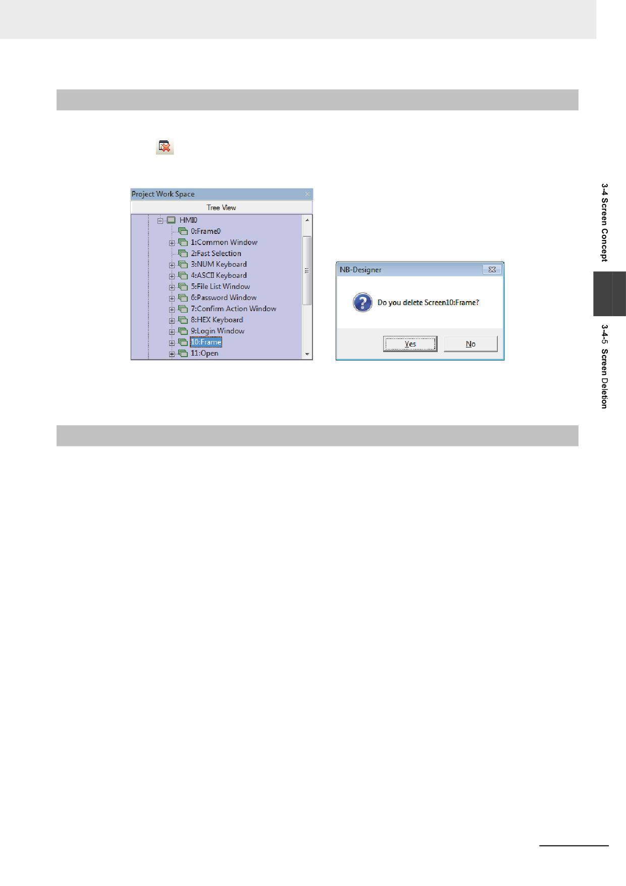
3-4-5
Screen Deletion
In Project Work Space, select the screen No. to be deleted, and press the “Delete” key in the keyboard
or click the
icon in [Screen Toolbar]. When the Confirm Screen pops up, select “Yes” to delete this
screen, and all the components in this screen will be deleted and can’t be restored. Please be careful
when you use this function.
3
Note Frame 0, Frame 1 to Frame 9 are all the default screens for the system, and they are not allowed to be
deleted.
3-4-6
Components Related to Screen
The function keys which are directly related to the screen operations include: Change Screen,
Backward, Change Common Screen, Pop-up Screen and Change Menu Screen. Components which
are directly related to the screen operations include: Direct Screen and Indirect Screen. For the
contents of these components, refer to 3-6-16 Indirect Screen (Page 3-147) and 3-6-17 Direct Screen
(Page 3-150).
NB-series Programmable Terminals NB-Designer Operation Manual(V106)
3-55
3 Functions of NB-Designer
3-5
Basic Design Method
3-5-1
Designing Components
Generally speaking, one screen includes various kinds of components such as switches, lamps,
number input and shapes. It is simple to add one component to the screen, and it is basically divided
into 3 procedures as shown below.
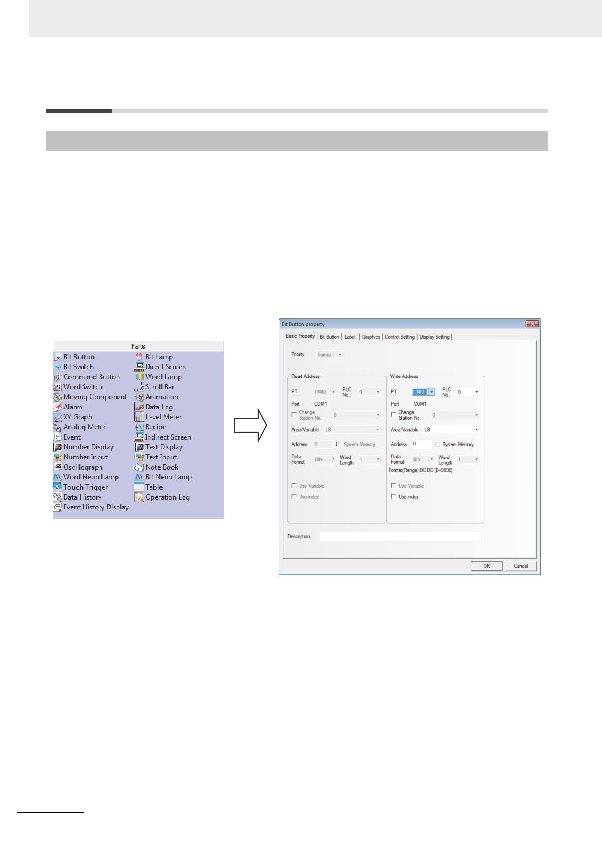
Component Addition
1
Drag the component icon from [Project Library Window]-[Parts] to the Edit Window.
2
When the Property dialog box of this component appears, set the various Properties for this
component such as PLC Read/Write Address, Vector Graphics or Bitmap, Label and Position
etc.
3
After the various Properties of this component are set, click the [OK] button. And you can see
this component has been placed in the screen after exiting from this dialog box. If required, you
can adjust the size of the component by changing settings in “Position” in “Display Setting” tab
or drag it to the desired position.
3-56
NB-series Programmable Terminals NB-Designer Operation Manual(V106)
3 Functions of NB-Designer
3-5-2
About ID No.
ID No. is the number automatically assigned to the component for differentiating the components on the
PT. The designer cannot change component ID number artificially.
The contents represented by ID No. are as follows:
BL0
0: Component No,
BL: Bit
Lamp
Parts:
SB: Bit Button
BL: Bit Lamp
3
SW: Bit Switch
DW: Direct Screen
SWD: Command Button
WL: Word Lamp
MSW: Word Switch
SCR: Scroll Bar
MV: Moving Component
ANI: Animation
AD: Alarm
TR: Data Log
XY: XY Graph
BR: Level Meter
MT: Analog Meter
RCP: Recipe
ED: Event
IDW: Indirect Screen
ND: Number Display
TD: Text Display
NI: Number Input
TI: Text Input
OS: Oscillograph
NB: Note Book
NL: Word Neon Lamp
BNL: Bit Neon Lamp
TT: Touch Trigger
GR: Table
HDD: Data History
NB-series Programmable Terminals NB-Designer Operation Manual(V106)
3-57
3 Functions of NB-Designer
Function Parts:
SC: Scale
FK: Function Key
AB: Alarm Display
TM: Timer
BG: Bitmap
VG: Vector Graphic
NP: Notepad
DT: Data Transmission
VM: Freeplotting
DTM: Date/Time Display
DG: Indirect Shape
UID: User Information
CO: Multifunction
EB: Event Display
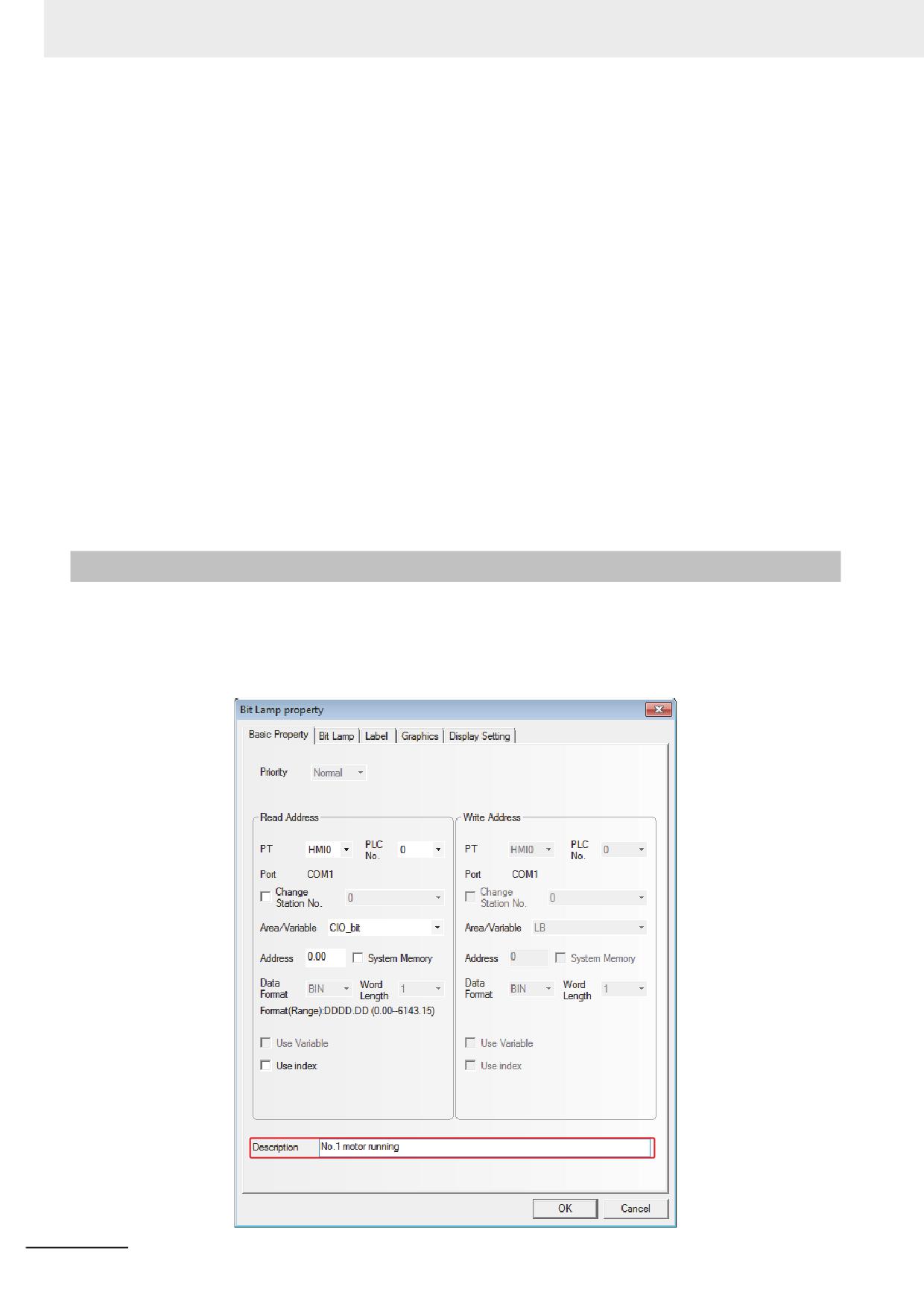
3-5-3
Additional Comments (Descriptions)
If necessary, you can add comments to each component. The comments are used for entering remarks
or descriptions of the program on creation. Therefore, the descriptions entered as the comments will be
referred in future or the text entered will be used to describe when the text is printing. The entered
comments will not cause any effects to the program. (The NB-Designer does not support comment
printing.)
3-58
NB-series Programmable Terminals NB-Designer Operation Manual(V106)
3 Functions of NB-Designer
3-5-4
Read/Write Address for PLC
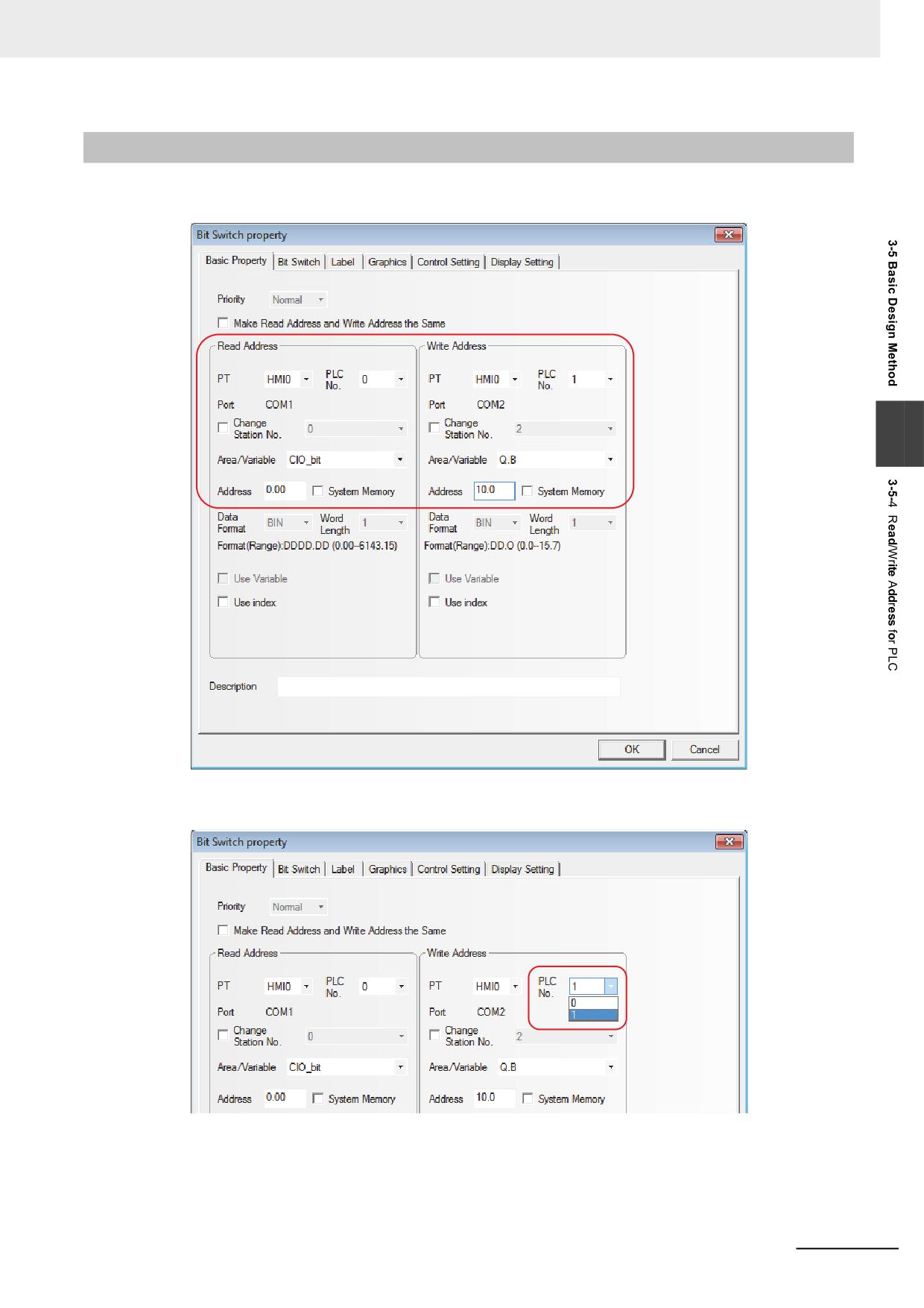
The correct area and address range vary with the PLC. In the following figure, PLC0 is manufactured
by OMRON, while PLC1 is manufactured by SIEMENS, so their addresses are different.
3
All the available PLC devices can be displayed in the pull-down menu corresponding to “PLC No.”
option.
NB-series Programmable Terminals NB-Designer Operation Manual(V106)
3-59
3 Functions of NB-Designer
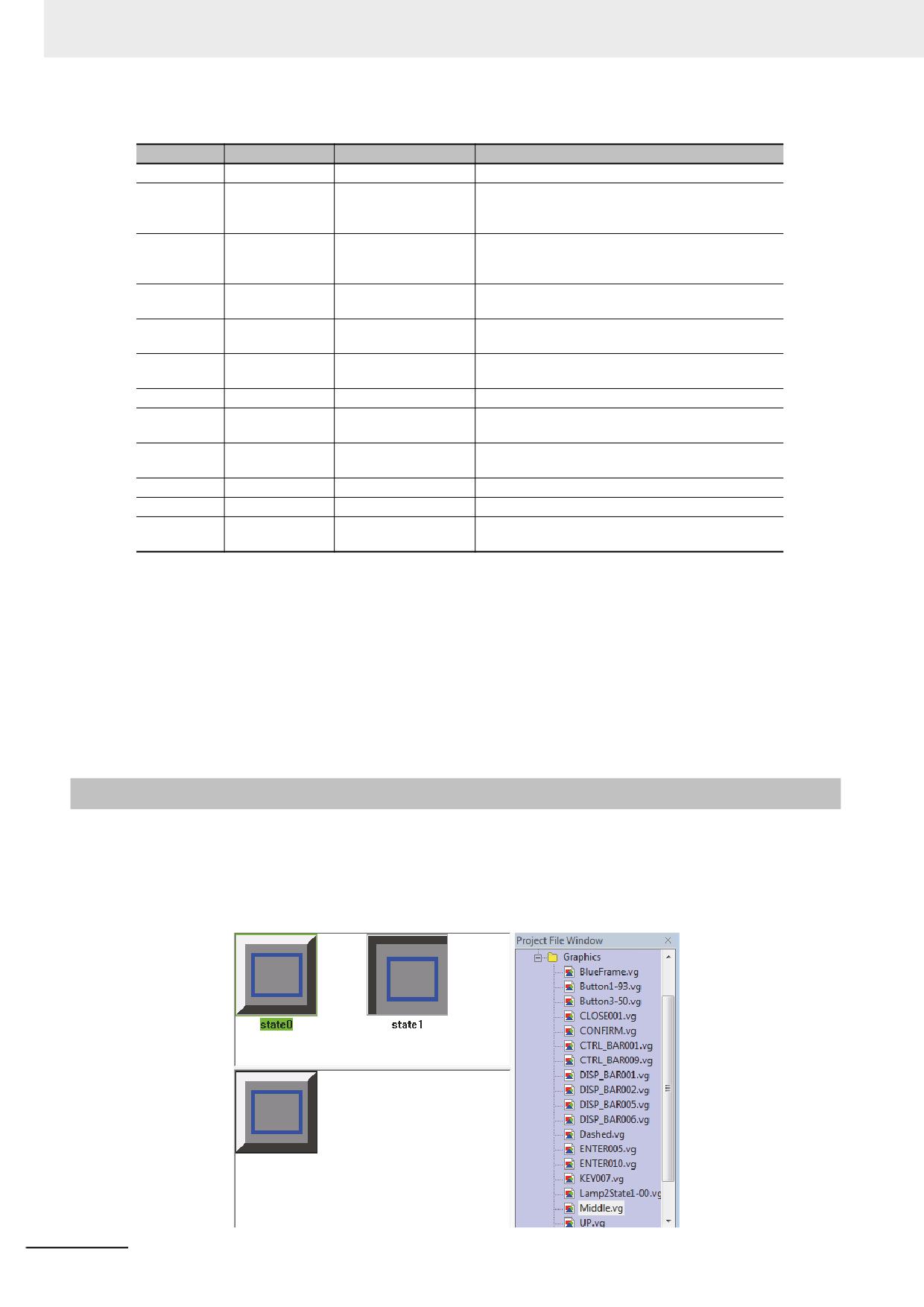
The internal memory can be also selected, And the descriptions of internal memory are as follows:
Type
Device Name
Range
Descriptions
Bit
LB
0~9999
The address of the local memory
Bit
RBI
0.0~261000.F(*1)
The index address of the recipe memory that is
stored in the flash memory in D.H. format and H
ranges from 0 to 15.
Bit
RB
0.0~261000.F(*1)
The absolute address of the recipe memory that
is stored in the flash memory in D.H. format and
H ranges from 0 to 15.
Bit
FRB
0.0~134217727.F
The absolute address of the flash memory in
D.H. format and H ranges from 0 to 15.
Bit
FRBI
0.0~134217727.F
The index address of the flash memory in D.H.
format and H ranges from 0 to 15.
Bit
LW.B
0.0~10255.F
The address of the local memory in D.H. format
and H ranges from 0 to 15.
Word
LW
0~10255
The address of the local memory
Word
RWI
0~261000(*2)
The index address of the recipe memory that is
stored in the flash memory
Word
RW
0~261000(*2)
The absolute address of the recipe memory that
is stored in the flash memory
Word
FRW
0~134217727
The absolute address of the flash memory
Word
FRWI
0~134217727
The index address of the flash memory
Word
ERW0~ERW2
0~2147483647
External Recipe Word Memory is available by
connection with the external memory.
RB and RW point to the same area. For example, RB5.0~RB5.15 and RW5 map the same area, i.e.
RB5.0 is the Bit0 of RW5. But the addresses pointed by LB and LW in the memory are different,
because they map the different areas.
The memory addresses of LB9000~LB9999 in LB, LW.B9000.0~LW.B10255.F in LW.B, and
LW9000~LW10255 in LW are reserved by the system internally for some special purposes, and the
users can’t use them as the addresses for the common devices, but should use their special functions
according to the related manuals. For details, refer to 3-11 Address of System Memory (Page 3-327).
When the recipe memory is accessed by the index address, the index address will begin to search from the address
of the offset of the address displayed by LW9000. For example: If LW9000 is 50, the index address RWI100 will
access the data in the address of RW150 (100+50). (For details, refer to 3-12 Recipe Data (Page 3-342).)
*1
When using NB3Q-TWB(-V1) or NB5Q-TWB(-V1), the range of addresses is 0.0 to 130500.F.
*2
When using NB3Q-TWB(-V1) or NB5Q-TWB(-V1), the range of addresses is 0 to 130500.
3-5-5
Vector Graphic
NB-Designer provides the powerful Vector Graphics and bitmap library, and you can create any desired
graphics (such as switch, lamp, piping etc.) in the library and even you can add your own pictures to the
library. The graphics can be 256-color bitmap, 16-color bitmap, 32-color bitmap or in JPG, BMP, GIF
and PNG format. Every vector graphics or bitmap can create 256 statuses. The created Vector
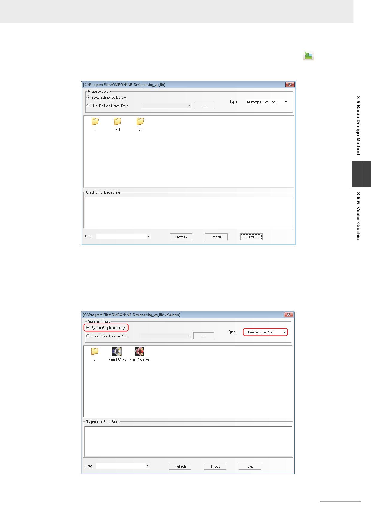
Graphics and bitmap are in [Graphics] in [Project File Window], as shown below:
3-60
NB-series Programmable Terminals NB-Designer Operation Manual(V106)
3 Functions of NB-Designer
Of course, you can use the graphics library provided by the system. When you click the
[Import
Graphics] icon in the toolbar, the following dialog box will pop up:
3
The system graphics library is located in bg_vg_lib\VG directory in which the NB-Designer was installed
and all the graphics are stored in the folders for each item. Select the Vector Graphics to be imported,
and click “Import”, then the Vector Graphics will be copied into the “vg” file of the current project.
Importing multiple Vector Graphics or bitmaps simultaneously is not supported and only one graphics in
the same folder can be selected at a time before “Import” is clicked. All the imported or created Vector
Graphics or bitmaps by the user in the whole project will be displayed in the [Vector Graphic] in [Project
File Window] to facilitate the user to view and use them.
The vector graphics can be used as static images or the images representing the status of various
components.
NB-series Programmable Terminals NB-Designer Operation Manual(V106)
3-61
3 Functions of NB-Designer
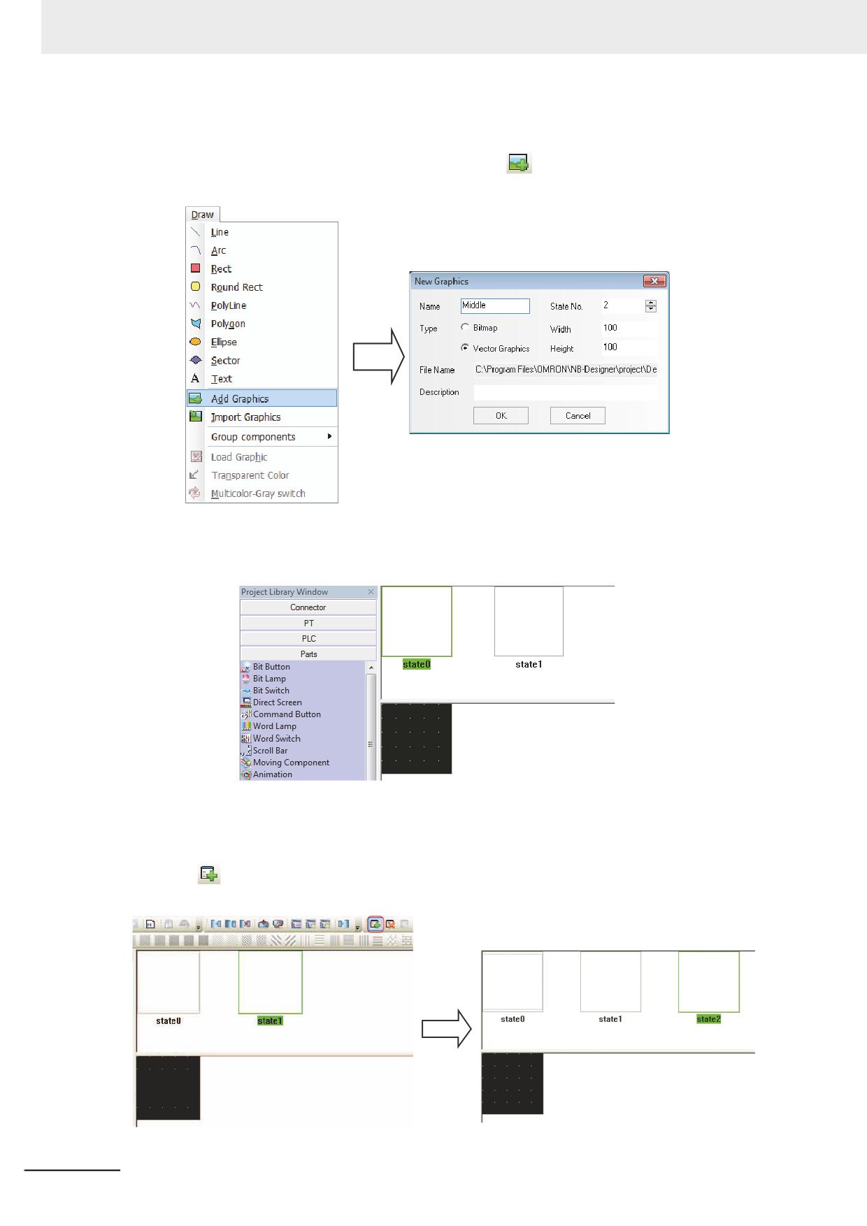
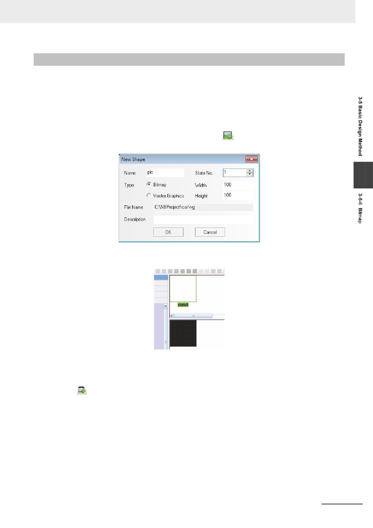
Procedure of Vector Graphics addition
1
Select [Add Graphics] in the [Draw] menu or click
icon in the toolbar, and then the
following dialog box will appear.
2
Input the Name, State No. and Description for the Vector Graphics (For example: To create a
Vector Graphics with the name of “Middle” and the state No. of “2”), and click “OK”, then the
following dialog box will appear:
If you think the Vector Graphics states added just now are not enough, you can use the following
methods to make addition:
Drag the mouse into State Preview Window of the Vector Graphics, select one state such as “state0”,
then click
icon in the toolbar to create a new state. And the states that can be created are up to
256 kinds.
3-62
NB-series Programmable Terminals NB-Designer Operation Manual(V106)
3 Functions of NB-Designer
3
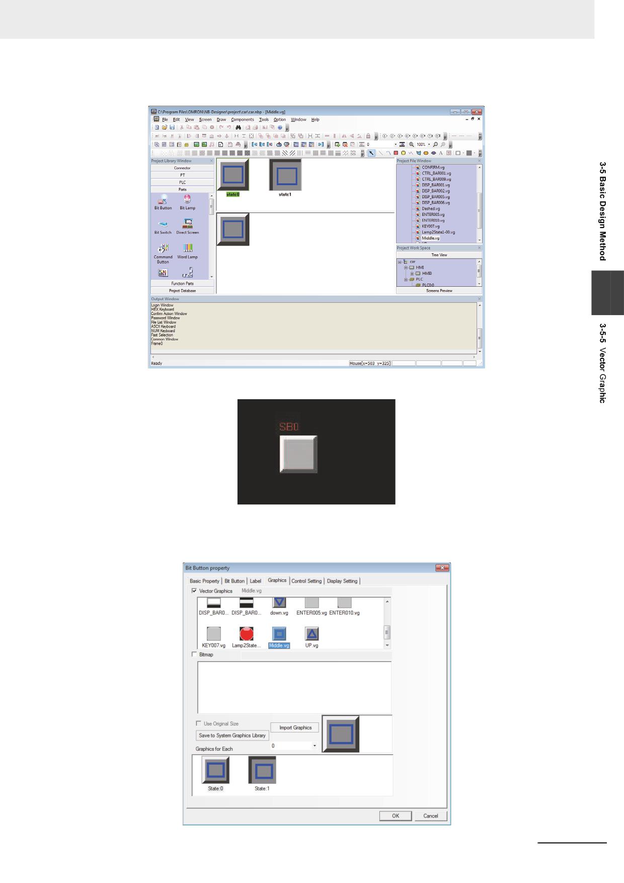
Create the graphics displayed in these two statuses, and then save the project.
3
4
Go back to the Edit Window, and select one component, as shown below:
5
Check [Vector Graphics] in the [Graphics] tab of Bit Button Property dialog box, and find the
name of the graphics created just now in the list, and then you can check the graphics at the
specific status each.
NB-series Programmable Terminals NB-Designer Operation Manual(V106)
3-63
3 Functions of NB-Designer
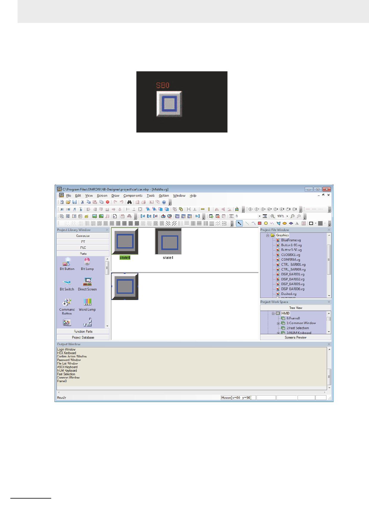
6
Click the [OK] button to exit from this dialog box, and this component will be displayed as the
selected Vector Graphics and placed in the screen.
All the Vector Graphics imported into the project will be displayed in the [Project File Window].
If you want to modify any Vector Graphics or bitmap, you just need to find the graphics to be modified in
the Vector Graphic in the Project File Window, and double-click it to open the Edit Window of this
graphics, where you can modify the graphics drawn by yourself.
Note 1
When the new graphics was created, the project should be saved to keep the contents. Otherwise the con-
tent will be lost.
2
No text can be added to the Vector Graphics.
3-64
NB-series Programmable Terminals NB-Designer Operation Manual(V106)
3 Functions of NB-Designer
3-5-6
Bitmap
One bitmap includes 256 kinds of states and the created bitmap can be used in the Edit Window. The
bitmap is mainly applicable to graphic area, i.e. external graphics addition.
Note The operations (such as line-drawing, drawing, text addition etc.) for the bitmaps can’t be made in the
Graphics Edit Window, and only the external graphics addition can be done.
Procedure of bitmap addition
1
Select [Add Graphics] in the [Draw] menu or click
icon, and then the following dialog box
will appear.
3
2
Select [Bitmap] in the “Type”, and input “State No.” and “Name”, then click “OK”.
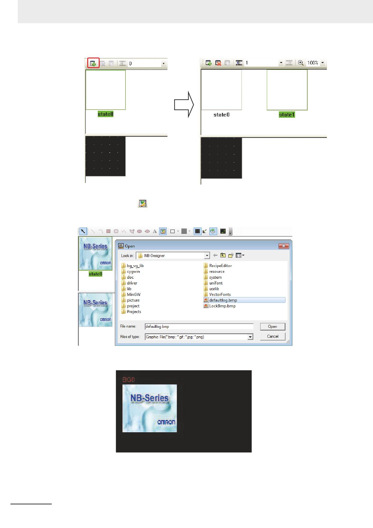
If you think the bitmap state added just now is not enough, you can use the following methods to make
addition:
Drag the mouse into State Preview Window of the bitmap, select one state such as “state0”, then
click
icon in the toolbar to create a new state. And the states that can be created are up to 256
kinds.
NB-series Programmable Terminals NB-Designer Operation Manual(V106)
3-65
3 Functions of NB-Designer
3
Click [Draw Toolbar]
icon, find the needed graphics, and click it to open it. Only the
pictures can be input into bitmap and the tools such as “Line” can’t be used in the bitmap, as
shown below.
4
After the project is saved, you can use it through the bitmap component in the Edit Window.
3-66
NB-series Programmable Terminals NB-Designer Operation Manual(V106)
3 Functions of NB-Designer
Use of Bitmap
1
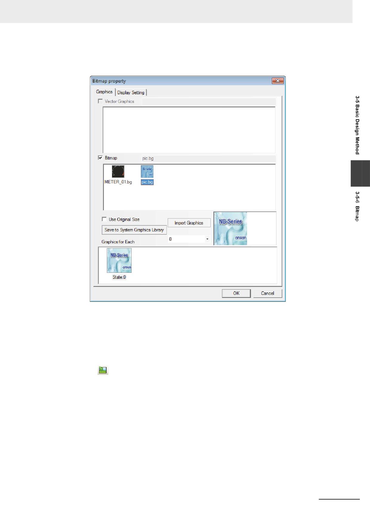
Double-click the component where the bitmap will be used and then enter “Graphics” tab.
3
2
Check “Bitmap” option, and select the bitmap you want to use, then click “OK” button to close
the dialog box.
Import of Bitmap
1
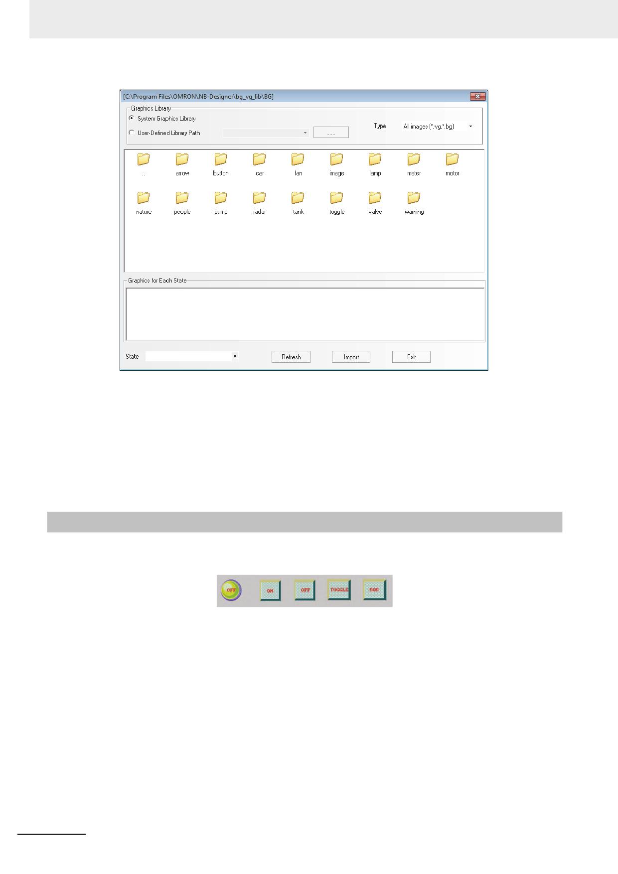
You can import the bitmap just like importing the Vector Graphics. Click “Import Graphics”
icon
, and select “Bitmap image (*.bg)” in the “Type” in the pop-up dialog box. You can
also import the bitmap used in the other project or the System Graphics Library. The system
graphics library is located in bg_vg_lib\VG directory in which the NB-Designer was installed
and all the graphics are stored in the folders for each item.
NB-series Programmable Terminals NB-Designer Operation Manual(V106)
3-67
3 Functions of NB-Designer
2
In the same project, the bitmap and the Vector Graphics are placed in the same location, i.e.
“VG” folder under “Project File” folder. And all the imported bitmaps are stored in
“project\<project file name>\image” folder. Don’t delete these pictures; otherwise the graphics
library will not be displayed normally.
Note There is no limitations for the size of the graphics imported (BMP, JPG, GIF, PNG), and the graphics will be
compressed according to the maximum used size (The maximum used size = Maximum length × Maximum
Width in the project) during the compilation.
3-5-7
Creating Label
Label refers to the text displayed in the surface of the components such as switch, lamp or the other
components.
Label Addition
1
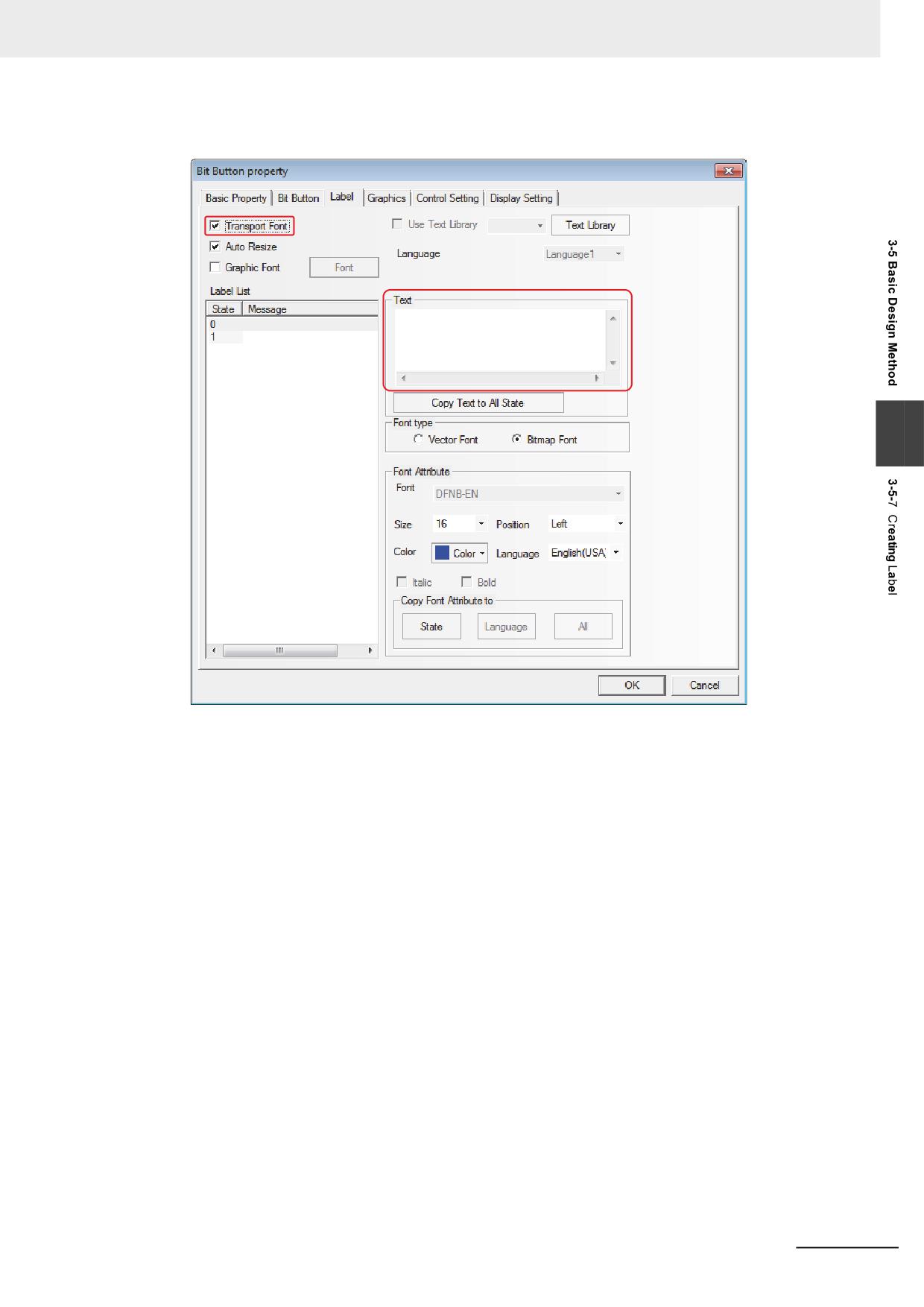
Select [Label] in the Property page of the selected component.
2
Check “Transport Font”.
3-68
NB-series Programmable Terminals NB-Designer Operation Manual(V106)
3 Functions of NB-Designer
3
As shown below, write the contents to be displayed for the label in [Message].
3
4
Set the display Properties such as the alignment method, font size and color etc.
5
Press the [OK] button to complete the setup.
State Number
State number is only effective for the component with multiple states. The text for every state can be
displayed independently. The text, font, color and alignment method for the corresponding state can
be set after the state is selected.
Message
Input the text to be displayed in the component surface here. If there are several lines, you can use
“Enter” key to break them.
Font Size
The size of Bitmap Font is as follows: 8, 16, 24, 32, 48, 64, 72, 96, 120 and 144 pixels.
Position
When the input text for the label is 2 lines or more, Left, Right or Center can be selected for the
alignment between the upper line and the lower line.
NB-series Programmable Terminals NB-Designer Operation Manual(V106)
3-69
3 Functions of NB-Designer
Color
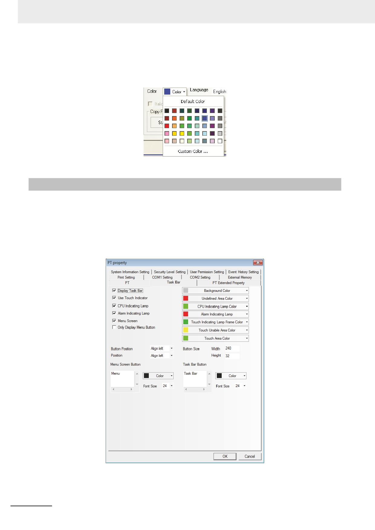
You can select color among 40 colors (65536 colors, which include supplementary colors). “Default
Color” palette contains the most commonly-used colors. “Custom Color…” palette allows the users
to customize the palette (65536 kinds of colors available).
3-5-8
Task Bar and Operation Buttons
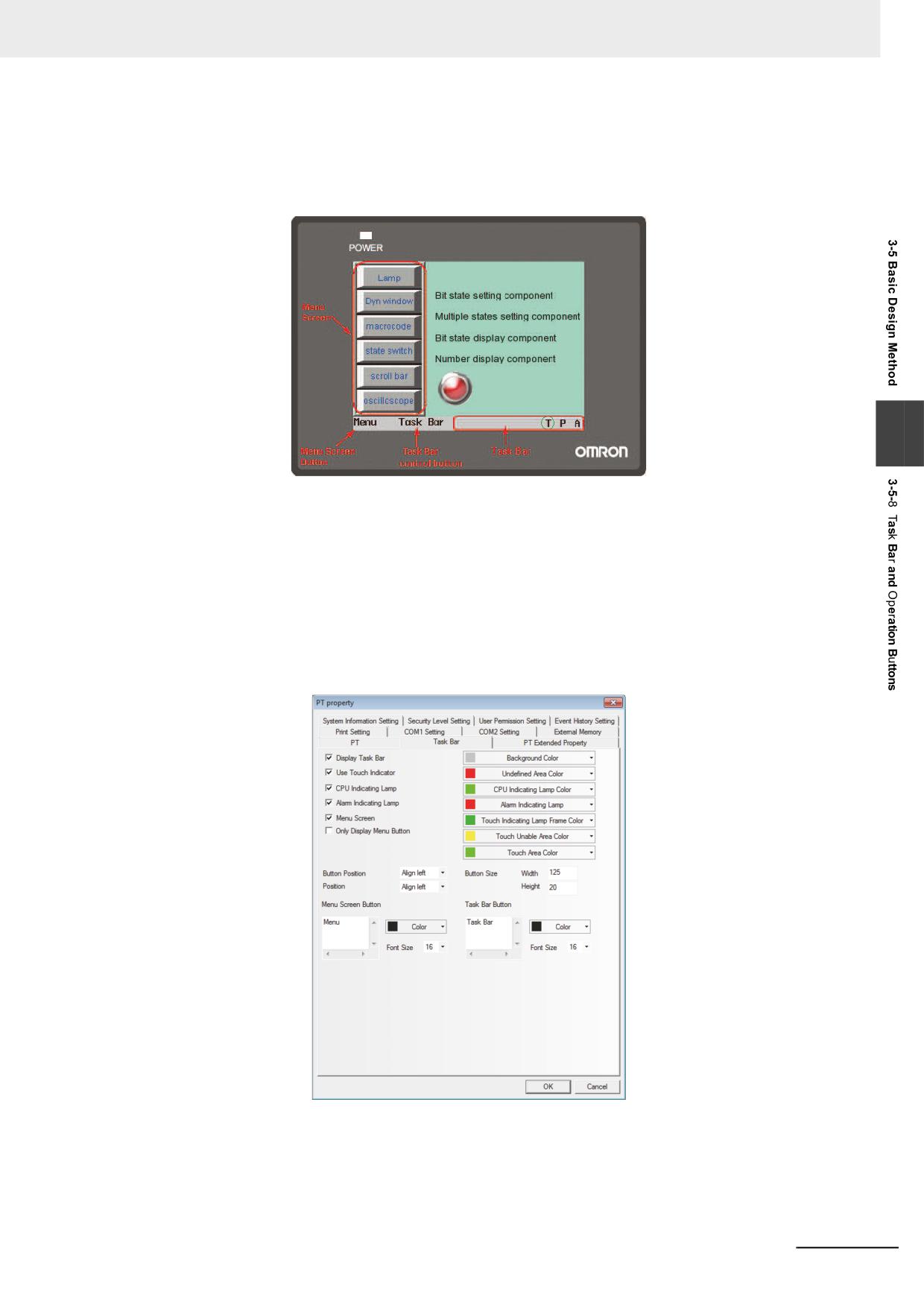
NB-Designer provides a simple method (i.e. the Task Bar) to make the screen pop up or be minimized,
to change the display of the screen and fast switch the screen display etc.
Task Bar has 2 operation buttons, one of which is used to control the Menu Screen, and the other is
used to control the Task Bar.
You can set the Properties such as the Task Bar, whether to use the Menu Screen, color and position
and so on in the [PT Property] in the Configuration and Setup Window. (By default, all the options in the
Display Task Bar are checked.)
3-70
NB-series Programmable Terminals NB-Designer Operation Manual(V106)
3 Functions of NB-Designer
If “Menu Screen” is checked, one Menu Screen will pop up when the Menu Screen button at the left
side is pressed. Function keys put in the Menu Screen allow the different screen switched. Because the
Menu Screen is always displayed on all of the screens, therefore it can be operated at any time. If you
want to switch to a certain screen, it just needs to press the function key pointing to the destination
screen once, thus avoiding the boring process of looking for the screen.
3
In the task bar, 16 icons can be arranged at the same time. The functions keys of [Minimize] or [Title
Bar in Pop-up Screen] included in Pop-up Screen allow the screens to minimize in the task bar. For
details, refer to 3-7-2 Function Key (Page 3-201).
Process of Operation Button Setup
Double click PT in the Configuration and Setup Window. Then the PT Property dialog box will appear,
and set [Display Task Bar], whether the operation button will locate in the left side or right side of the
screen, the backg1round color and the text position method of the taskbar in [Task Bar] tab. If the label
isn’t displayed completely, you can adjust the width or the height of the button area and the font size of
the label to solve this problem.
Note The Menu Screen is displayed on the left side or the right side of the panel during the operation. In edit
window state, the Menu Screen is an independent screen, and it is Frame 2 by default. For details, refer to 3-
10-2 Task Bar (Page 3-293).
NB-series Programmable Terminals NB-Designer Operation Manual(V106)
3-71
3 Functions of NB-Designer
3-5-9
Fonts
Type and Characteristics of Font
NB-Designer provides 3 available fonts, i.e. Bitmap Font, graphic font and vector font. The
characteristics of these three fonts will be described as follows:
Bitmap Font :
One bitmap font is prepared for each character. But this method has obvious disadvantages:
(a) Only SimSun is supported.
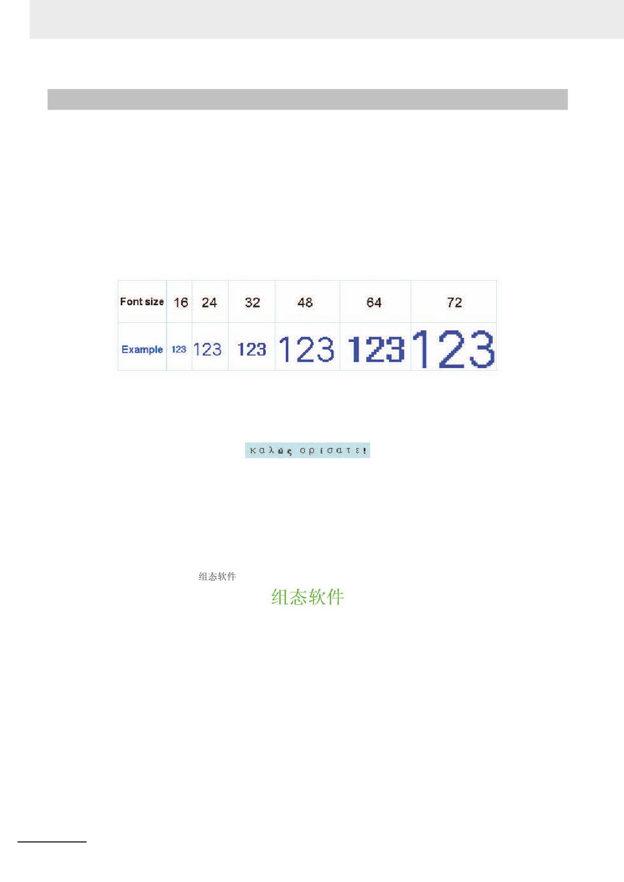
(b) The scaling effect is poor. For each character, 3 kinds of bitmaps (i.e. 8×8, 16×8, 24×16(height ×
width)) are reserved respectively, so the effect is very poor when the larger font is displayed, as
shown below:
(c) Single-byte character may be treated as double-byte character. ASCII code is treated as a single-
byte character, but the other character are converted to double-byte character in the software.
Therefore, a character varies in its width for each character (such as Russian) cannot be displayed
correctly.
Therefore, this method has the obvious disadvantages for the project with multiple languages.
Graphic Font:
Graphic font is converted to one bitmap and stored in the project. This method can make full use of the
fonts installed in Windows and the display effect is good.
(a) The capacity of the project becomes greater. There are 2 reasons for the large space needed for
saving the character string as bitmap. First, bitmap format itself needs a large space. For example:
Four characters “
” displayed in Zero SimSun needs 1824 bytes, as shown below:
In addition, the bitmap font should be intercepted again if the content, size or colors vary slightly,
thus causing a linear increase in the occupied space.
When a character is converted as a bitmap, it is converted as the unit of character string, not the
unit of the character. Even if a similar character is different with its content, font size, color, the
character is converted as an individual bitmap. As the converted bitmaps are stored in the NB
project file for each character string with different properties as above, the capacity occupied with
the fonts should be increased in the project.
(b) Text library or some component labels do not support the graphic font.
Vector Font:
The characters used for labels or supposed to be used in future are abstracted through specified fonts
by NB-Designer. Only the abstracted characters are stored as True Type font (ttf style) and can be used
by the NB-Designer units.
Using vector font in NB-Designer can avoid the disadvantages of Bitmap Font and graphic font.
Vector font has the following advantages:
3-72
NB-series Programmable Terminals NB-Designer Operation Manual(V106)
3 Functions of NB-Designer
(a) It supports a large variety of vector fonts. The TrueType font (only the font in ttf format) installed in
the operating system can be used.
(b) You can save the capacity of project file. It adopts the method of intercepting the matrix from the
font file, thus reducing the capacity of the font file. For the same character in the same font, only
one matrix needs to be intercepted regardless of the size, color, bold/italic styles.
(c) Rich font styles are available. Bold and italic styles are available for each kind of font.
(d) The font size can be set freely without any deformation. You can set the consecutive font sizes
without any projections.
(e) It supports powerful multiple languages. You can use it to set fonts for each state and each kind of
language of the text.
(f) The vector font can be used in the text library.
Use of Vector Font
The functions and components related to the vector font are as follows:
3
1
Text Library
Using the text library can realize the reuse of the text and the multi-language project.
The operation instructions related to the font:
(a)
Maximum language number setup
The maximum language number can be set up to 32. If smaller capacity of project file is preferable,
set the maximum language number to the least necessary number.
(b)
Default font setup for each language
The user can set the default font for each language, and when the user uses the text library, he
doesn’t need to reselect the font each time.
2
Text Component
Text component can display the character information statically. And the user can use the multi-
language text when the text library is used.
(a)
The text component can use 3 kinds of fonts, i.e. Bitmap Font , graphic font and vector font.
(b)
In the text library mode, the text component can reset the font for each language by changing the
language displayed currently.
3
Label
Most of the components can use the label. The text string can be directly input and the text library
can also be used in the component label.
(a)
When the text library isn’t used, different fonts can be set for text string in each state.
(b)
When the text library is used, fonts can be set for the text string of each language and in each
state.
4
Component dealing with numbers
Number components include number input component and number display component.
After the vector font is set for the number input component, the content of the number input
component will be displayed as vector font to realize the better display effect.
5
Component dealing with text strings
Text components include text string input component, text display component and note book
component.
NB-series Programmable Terminals NB-Designer Operation Manual(V106)
3-73
3 Functions of NB-Designer
(a) Limitations to ASCII codes for the vector font: The text contents used for the component dealing
with text string often can’t be decided during the compilation of the project, and due to the
limitations to the storage capacity, all the characters that may be used can’t be downloaded to the
PT. Therefore, these components can only use ASCII characters (The matrix information
supporting all the ASCII characters for this font have been downloaded to the PT by the software.)
when using the vector font.
(b) Unicode character encoding. When the Bitmap Font and the Unicode are selected simultaneously,
you can use the function key to input Unicode character to the text input component.
6 Time Component
Time component can display the information such as year, month, day, hour, minute, second and
week etc. of the current system in the simplest way.
When the vector font is selected, the time will be displayed according to the set vector font.
7 List and Drop-down List
List and drop-down list options are available for selection in the Word Switch component, and in
such state, the label for the component is listed as the list. Similarly, fonts can be set for each
language and each state.
8 Alarm and Event Information
Alarm and event information component can also set different vector fonts for each piece of alarm
information and for each language (When the text library is used.) respectively.
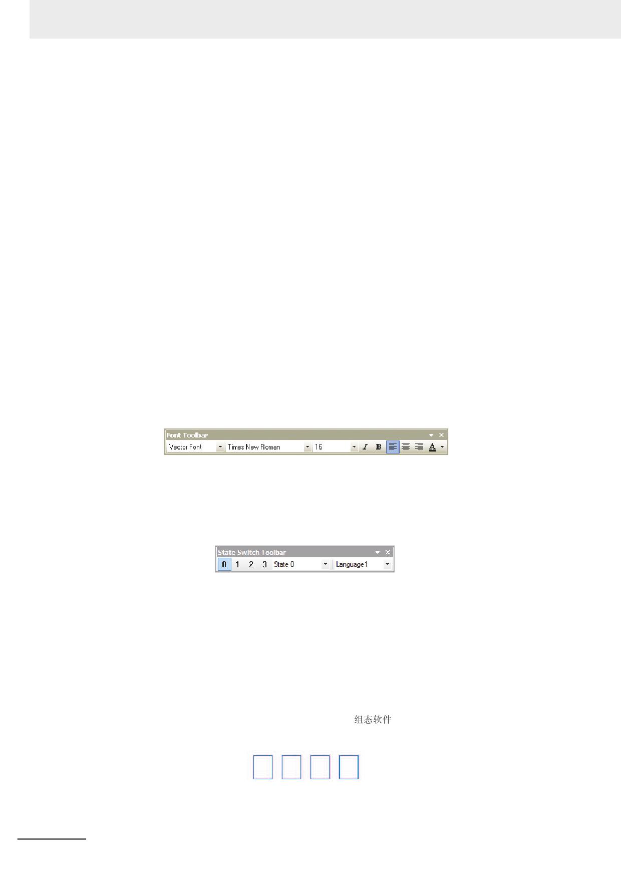
Use of Font Toolbar
The software provides the toolbar for convenient font operation. When you select one or more
components, you can use the font toolbar to change the font Properties of the related components.
Please pay attention to the following conditions:
(a) The font attributes set through the toolbar for the current state and current language. If the
attributes of other states and languages need to be changed, you can do it through the component
dialog box or by changing the current state or the current language of the project, as shown below:
(b) When multiple components are selected, if the component doesn’t support a certain font attribute,
the attribute of this component will not be affected by using the font toolbar to set the font attribute.
Notes for Using Vector Font
Based on the special realizing method for the vector font, the following conditions should be paid
attention to when the vector font is used:
1 If the font which is not supported for text to be displayed is used, the font cannot be displayed
correctly.
For example, if you want to display four characters “
” using Arial font, but because these
four characters are not included in the Arial character set, so four square boxes will be displayed in
this case, as shown below. Therefore, you must select the fonts supporting text to be displayed.
3-74
NB-series Programmable Terminals NB-Designer Operation Manual(V106)
3 Functions of NB-Designer
2 Use the vector font as much as possible if the smaller capacity of project file is preferable.
Because the Bitmap Font and graphic font have many disadvantages in the storage space and
resizing etc, therefore, use the vector font as much as possible.
3 The types of the vector font can be reduced when the screen can meet the requirements.
If too many types of vector fonts (e.g. dozens or more) are used by the user, the number of font
files will be too many, thus affecting the compilation speed, downloading speed and screen
switching speed.
4 Install the same fonts for all the PC environments to edit text strings.
If a certain project uses “Microsoft Elegant Black” font when it is edited on PC, and when it is
transferred to another PC where no “Microsoft Elegant Black” font exists for editing, then all the
“Microsoft Elegant Black” characters used in the project will be changed to arbitrary font which is
decided as optimal by the operation system.
3
Note When the font installed with Windows is used, use it only after confirming the font will not give rise to
3-5-10
Basic Properties of Component
Basic Properties of Component
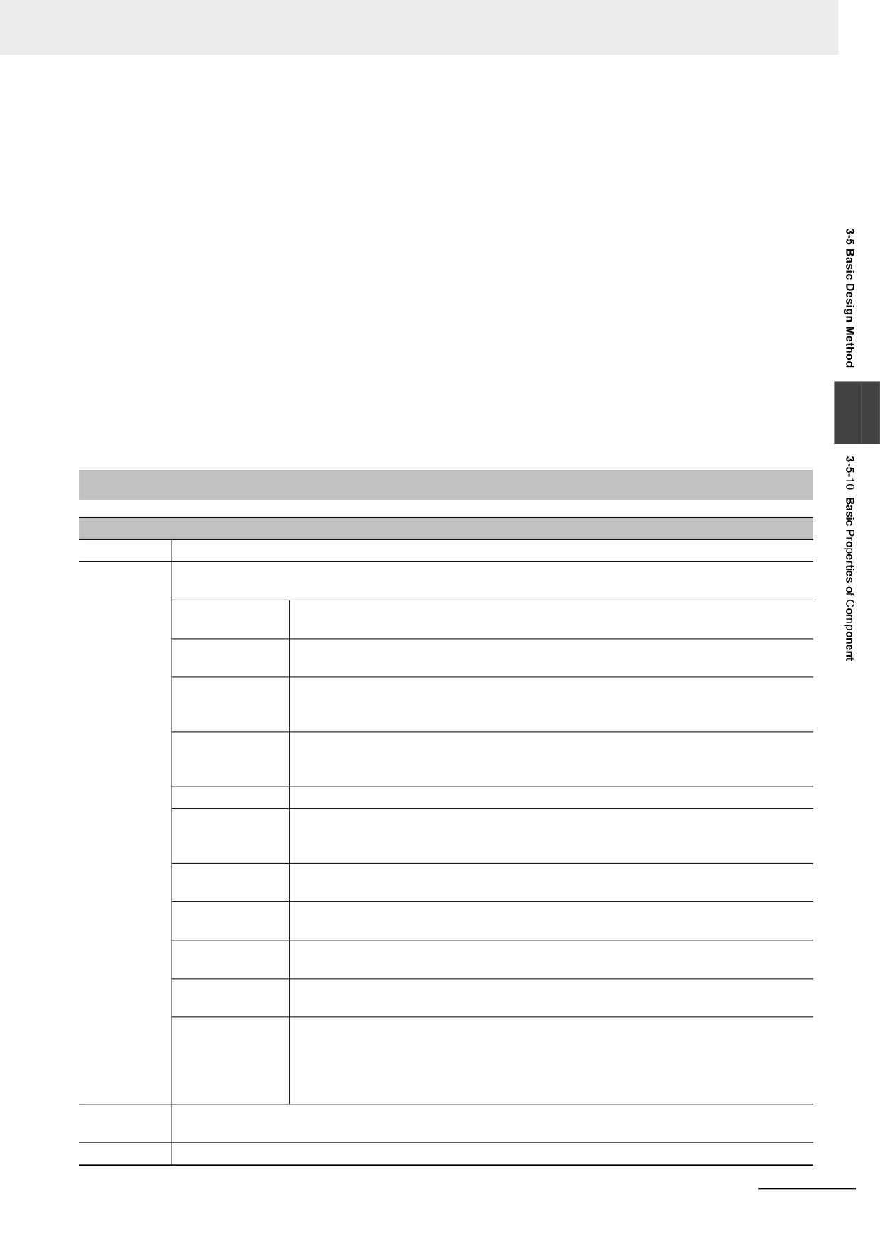
Priority
It is pre-reserved for the function.
Write
If the component supports read only, you cannot set to writing addresses. The status of the components will
Address
be displayed based on the reading addresses.
PT
Number of the controlled PT. The numbers are allocated automatically when the PT is
placed on [Configuration and Setup Window].
PLC No.
Number of the controlled PLC. The numbers are allocated automatically when the PLC
is placed on [Configuration and Setup Window].
Change Station
This option can be used to access the specific PLC during the communication with
Number
multiple PLCs. This option is applicable when editing only one PLC in the case one PT
is connected with multiple devices or multiple PTs are connected with multiple devices.
Area/Variable
Refers to the memory of PLC device to be controlled or the internal memory of the PT.
For the internal address type of PT, refer to 3-5-4 Read/Write Address for PLC (Page 3-
59).
Address
Specifies address to be written to.
Data Format
The code type includes BIN, BCD, and LSB. When BIN or BCD code is used, it allows
to display 256 of statuses at maximum and when LSB code is used, it allows to display
17 of statuses at maximum. (Refer to 10 LSB Type (Page 3-378) in the section 3-16).
Word Length
Refers to the number of the occupied memories. The default number is 1, and it varies
with the different component or area/variable.
System memory
Refers to the internal memories provided by the PT for some special purposes. For
details, refer to 3-11 Address of System Memory (Page 3-327).
Format (Range)
Refers to the formats of the address types of the PLC memories or the internal memory
address of the PT.
Use Variable
Determines whether to use the addresses registered in the variables. For details, refer
to 3-8-2 Variable Table (Page 3-244).
Use the index
Determines whether to use the specified memory as the index memory for the control
memory
memory of the current component. The new [Read/Write Address] = the specified
[Read/Write Address] + [Index Address]. For example, when the specified written
address is D100 and the index memory address is LW0, if LW0=10, the new write
address is D100+10=D110.
Read
If the component supports write only, you cannot set to reading addresses. The status of the components
Address
will be displayed based on the writing addresses.
Description
Refers to the reference name assigned to the current component (not displayed).
NB-series Programmable Terminals NB-Designer Operation Manual(V106)
3-75
3 Functions of NB-Designer
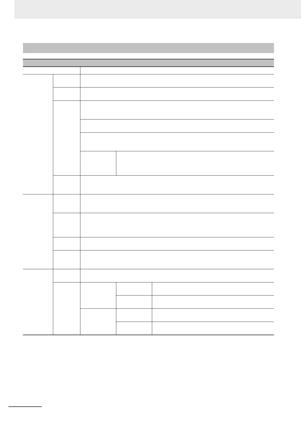
3-5-11
Control Setting of Component
Control Setting of Component
Option
Descriptions
Touch
Enable
Checking this option means the state value can be written into the controller by triggering the
Enabling
Input
effective area for the current component.
Setting
Disable
Checking this option means the state value cannot be written into the controller even when
Input
triggering the effective touching area for the current component.
Conditional
Security Level: Checking this option means only when the security level of the operator is
Enabling
higher than the minimum security level already set, the current component can be touched,
and the state value can be written into the controller.
User Permission Control: Checking this option means the operator must have the permission
to touch the current component and write the state value into the controller.
Indirect reference: Checking this option means only when the state of the specified bit memory
or word memory meets the set conditions, the current component can be touched, and the
state value can be written into the controller.
Auto show
Checking this option means the Password Input Screen Frame 9 (Login
login screen
screen) will pop up automatically for the user to login when the security level
or the permission of the current user doesn’t meet the requirement of the set
level or authority.
Show
Checking this option allows Unable-to-Input figure will be displayed when the component is in
Unable-to-
invalid to input. This function is optional only when [Enable Input] or [Conditional Enabling] is
Input
checked; and touching invalid color can be set in [PT Property]-[PT Extended Properties].
Security
ON Delay
When the current component is pressed consecutively for this set time, the state value can be
Setting
written only to the controller. The minimum unit is 100 ms. When this option is 0, this function is
invalid.
Confirm
Checking this option means the Confirmation Screen will pop up automatically when the
Operation
current component is touched, and the state value can be written into the controller when
“YES” is clicked, while the operation will be cancelled automatically when the user have clicked
“Cancel” or haven’t confirmed “YES” after the set “wait[s]” is exceeded.
Operation
Checking this option means the operation event will be recorded, and displayed through the
Log
operation log element and the file in CSV format will be saved into the external memory.
Min Inteval
Refers to the minimum interval between 2 operations for the same component or different
components. The minimum unit is second. When this option is 0, the minimum interval is
invalid.
Triggering
Macro
Checking this check box allows the macro which was specified before the current operation
action
was completed will be triggered and executed. *
Write
Word
Notice Before
Writes the write-value into the specified address before the
Notice
Written
current operation is performed successfully.
Notice After
Writes the write-value into the specified address after the
Written
current operation is performed successfully.
Bit
Notice Before
Writes ON/OFF signal into the specified address before
Written
the current operation is performed successfully.
Notice After
Writes ON/OFF signal into the specified address after the
Written
current operation is performed successfully.
* Please refer to 3-9-3 Macro Triggering (Page 3-273).
3-76
NB-series Programmable Terminals NB-Designer Operation Manual(V106)
3 Functions of NB-Designer
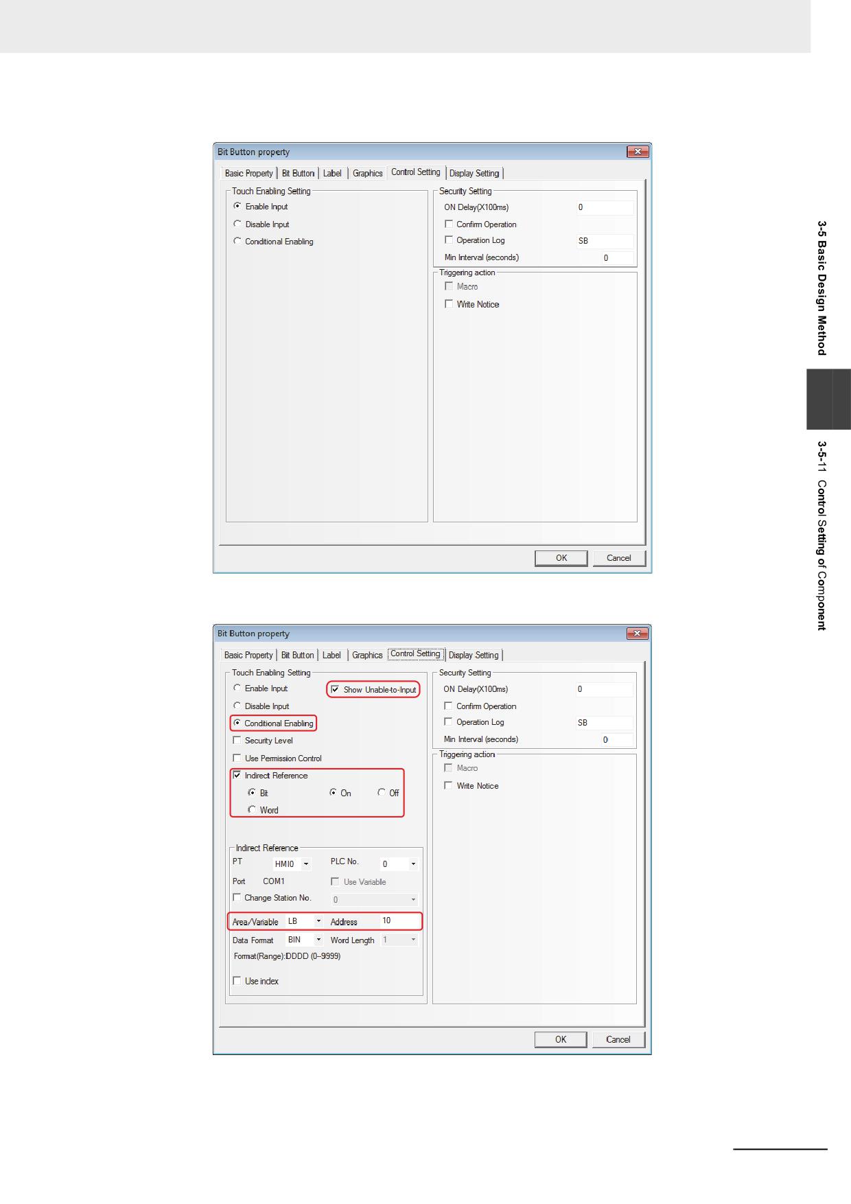
Example of Control Setting
3
Example: Setting the parameters as below to enable the value input to LW0 when LB10 is ON.
NB-series Programmable Terminals NB-Designer Operation Manual(V106)
3-77
3 Functions of NB-Designer
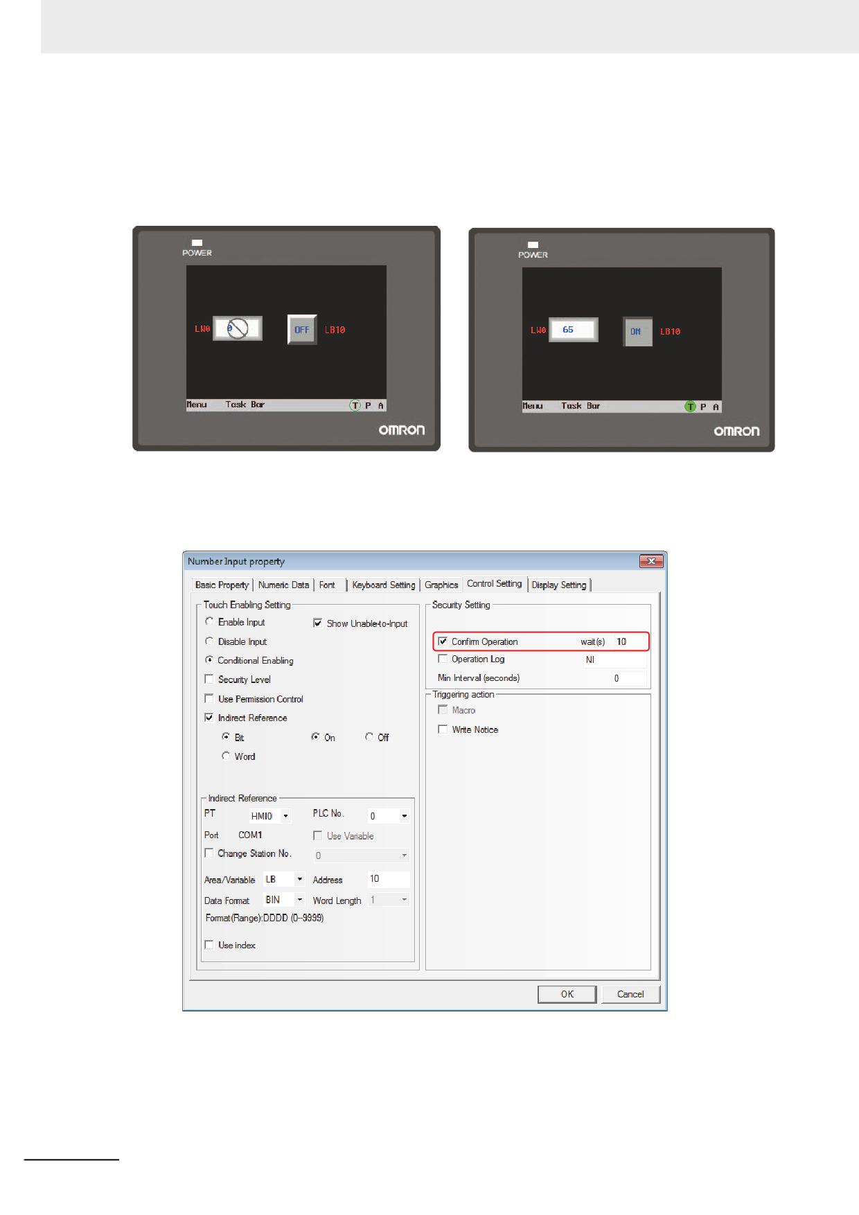
1 Perform the offline test. When LB10 is OFF, the input by the number input component is invalid,
and the icon indicating [Unable-to-Input] is displayed, as shown in the following left graphics.
2 When LB10 is ON, the input by the number input component is valid, and the icon indicating
[Unable-to-Input] isn’t displayed as shown in the following right graphics.
Example of Security Setting
Example: Set LW0 to the address of number input component, check Operator Comfirm, and select
10 s for “wait[s]”.
3-78
NB-series Programmable Terminals NB-Designer Operation Manual(V106)
3 Functions of NB-Designer
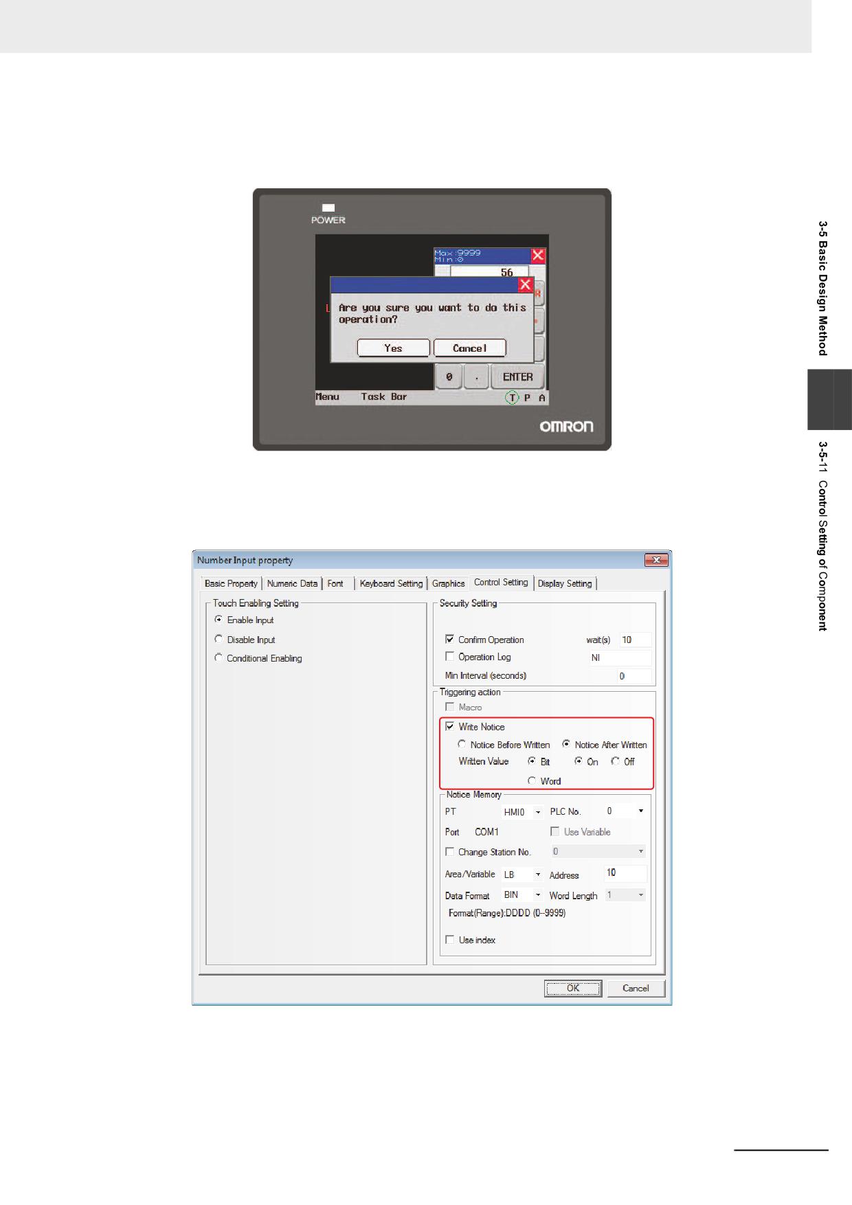
Perform the offline test. Operate the number input component, and the Confirm Screen will pop up
during the confirmation operation. In this case, press “Yes” to input the data successfully, press
“Cancel” to cancel the input. If 10 seconds pass without pressing “Yes” nor “Cancel”, the
Confirmation Screen will disappear automatically.
3
Example of Notifications
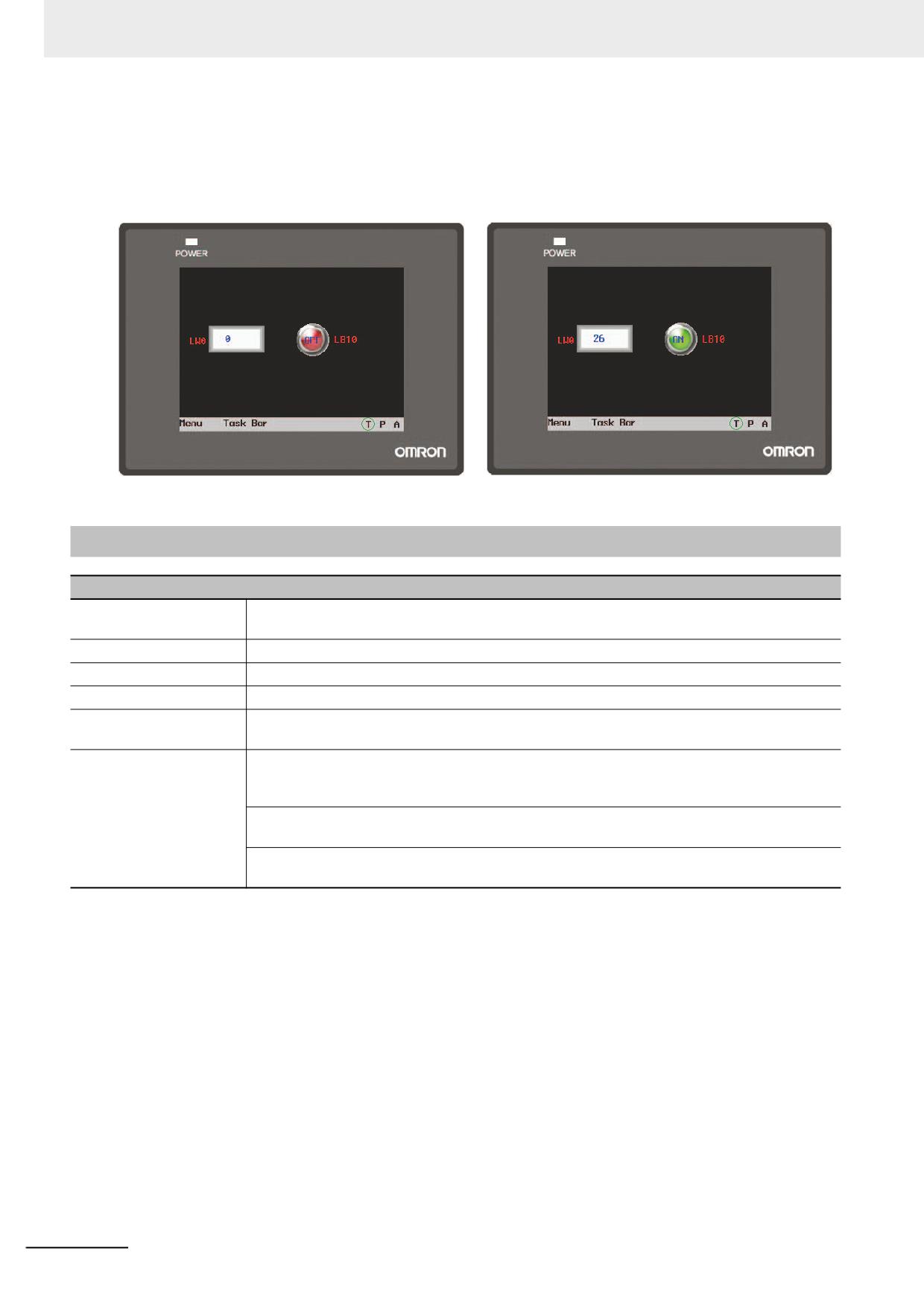
Example: Set LW0 to the address of number input component. Set After Written Notice as LB10 is
ON after writing the address.
NB-series Programmable Terminals NB-Designer Operation Manual(V106)
3-79
3 Functions of NB-Designer
Perform the offline test. And when no data is written into the number input component LW0, LB10 is
“Off”, as shown in the following left graphics.
When the data is written into the number input component, LB10 is “On”, as shown in the following
right graphics.
3-5-12
Display Setting of Component
Display Setting for Component
Lock Position
Checking this option means the component is locked. Once the component is locked, it can’t
be moved by the mouse or the moving keys in the keyboard.
X/Y
Refers to the coordinate value of the vertex in the upper-left of the component.
Width/Height
Refers to the width and height of the component (The unit is pixel point).
Display
Checking this option means the current component is always in displayed state.
Not Display
Checking this option means the current component is always in “hide state” and the touching is
[Touching is invalid]
invalid when the component is hidden.
Conditional Display
Security Level Control: Checking this option means the current component can be displayed
only when the security level of the operator is higher than the minimum security level already
set.
User Permission Control: Checking this option means the current component can be displayed
only when the operator has the set permission.
Indirect Reference: Checking this option means the current component can be displayed only
when the state of the specified bit memory or word memory meets the set conditions.
3-80
NB-series Programmable Terminals NB-Designer Operation Manual(V106)
3 Functions of NB-Designer
Example of Display Setting
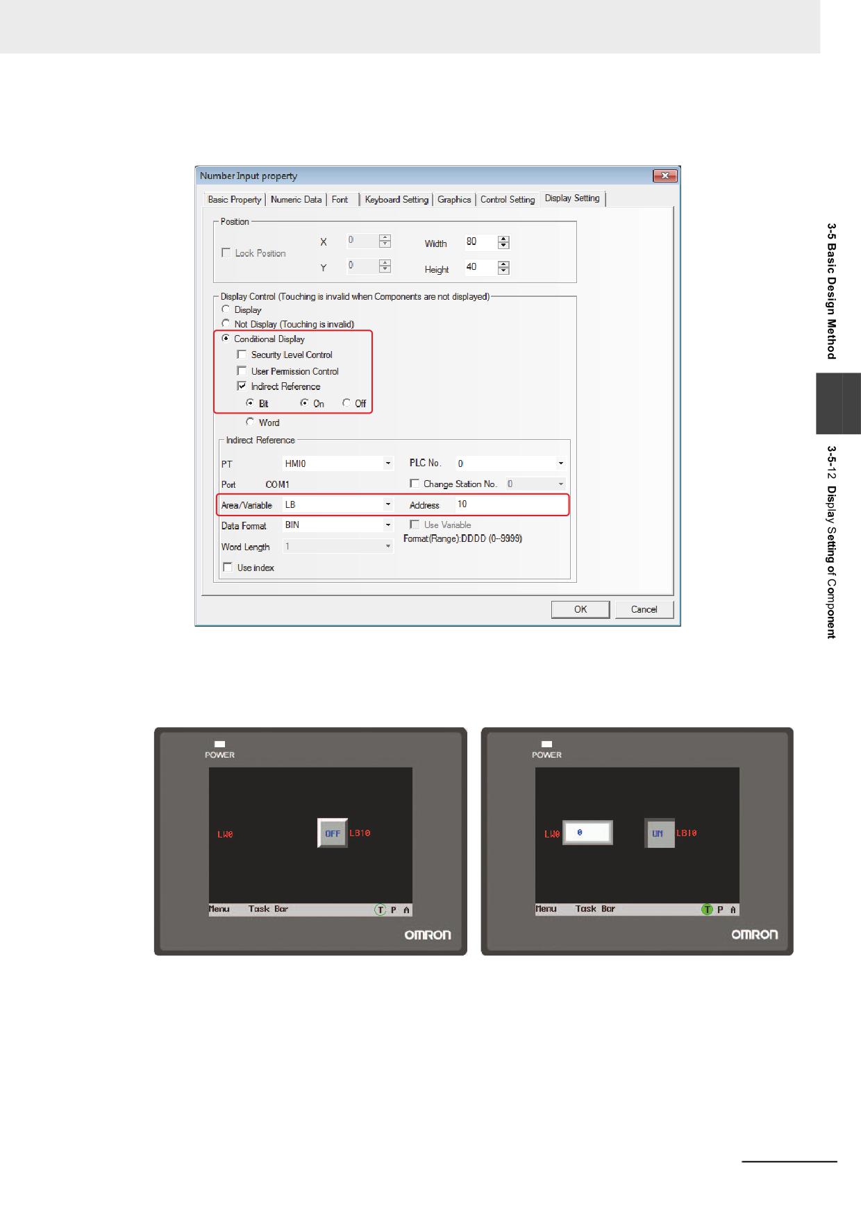
Example: Set LW0 to the address of number input component make display setting and keep LB10 as “On”.
3
Perform the offline test. When LB10 is Off, the number input component is hidden, as shown in the
following left graphics.
When LB10 is On, the number input component is displayed, as shown in the following right
graphics.
NB-series Programmable Terminals NB-Designer Operation Manual(V106)
3-81

3 Functions of NB-Designer
3-6
Parts
Parts are designed to meet specific needs. Generally speaking, one component can realize one
function, but some components should be combined with the related components or PLC to realize
some specific functions, as shown below.
Components
Related Components
Descriptions
Number Input
Function Key
To create the keyboard by “Function Key”
Text Input
Function Key
To create the keyboard by “Function Key”
Indirect Screen
Screen
The created “screen”
Direct Screen
Screen
The created “screen”
Alarm Setting
Alarm, Alarm Display
To display the registered alarm information by “Alarm”
or “Alarm Display”
Alarm
Alarm Setting
To display the alarm information registered by “Alarm
Setting” component
Alarm Display
Alarm Setting
To display the alarm information registered by “Alarm
Setting” component
Event Setting
Event
To display the registered event by “Event” component
Event
Event Setting
To display the event registered by “Event Setting”
component
PLC Control
PLC
To make PLC program control the operations of the
functions
Most of the PLC part support “bit” or “word” addresses (“Double-word” operation can be performed by
some components such as Number Input and Scroll Bar etc. Due to some PLCs have “double-word”
addresses, so some PLC drivers will make conversion between “double-word” and “word”, and the user
must pay special attentions to the instructions of PLC driver.
3-6-1
Bit Button
Bit Button component defines one touching area. When this area is activated, the bit
address inside the PT or in the PLC can be switched to “On” or “Off” forcefully.
3-82
NB-series Programmable Terminals NB-Designer Operation Manual(V106)
3 Functions of NB-Designer
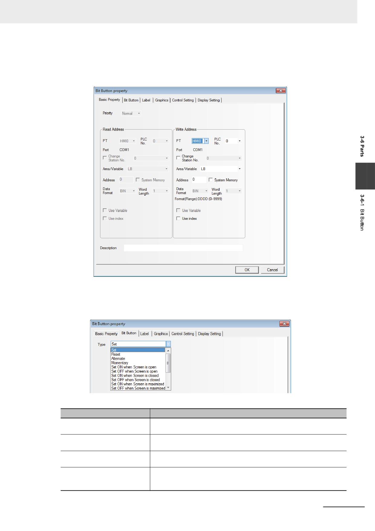
Process of adding one Bit Button component
1
Drag the Bit Button component after it is pressed will make the [Basic Properties] of Bit Button
component pop up.
3
Write Address:Refers to the bit address corresponding to “On” or “Off” state controlled by the
Bit Button component.
2
Switch to the [Bit Button] tab.
Types and Functions of Bit Button Component
Type
Descriptions
Set
The specified bit address will turn On when the Bit Button component is
pressed. This state will continue even if the button is released.
Reset
The specified bit address will turn Off when the Bit Button component is
pressed. This state will continue even if the button is released.
Alternate
The specified bit address will change once (OnOff, OffOn) (Switched
back and forth) when the Bit Button component is pressed each time.
Momentary
The specified bit address will turn On only when the Bit Button component is
being pressed. Similarly, the bit address will turn Off when the component is
released.
NB-series Programmable Terminals NB-Designer Operation Manual(V106)
3-83

3 Functions of NB-Designer
Type
Descriptions
Set On when Screen Open
The specified bit address will turn On when the screen containing the Bit
Button component is opened.
Set Off when Screen Open
The specified bit address will turn Off when the screen containing the Bit
Button component is opened.
Set On when Screen Close
The specified bit address will turn On when the screen containing the Bit
Button component is closed.
Set Off when Screen Close
The specified bit address will turn Off when the screen containing the Bit
Button component is closed.
Set On when Screen Maximized
The specified bit address will turn On when the screen containing the Bit
Button component is maximized.
Set Off when Screen Maximized
The specified bit address will turn Off when the screen containing the Bit
Button component is maximized.
Set On when Screen Minimized
The specified bit address will turn On when the screen containing the Bit
Button component is minimized.
Set Off when Screen Minimized
The specified bit address will turn Off when the screen containing the Bit
Button component is minimized.
Set On when Backlight Off
The specified bit address will turn On when the screen containing the Bit
Button component is displayed in the screen and the backlight is Off.
Set Off when Backlight Off
The specified bit address will turn Off when the screen containing the Bit
Button component is displayed in the screen and the backlight is Off.
Set On when Input Success
The specified bit address will turn On when the input using one Number Input
component in the screen containing the Bit Button component is successful.
Set Off when Input Success
The specified bit address will turn Off when the input using one Number Input
component in the screen containing the Bit Button component is successful.
3
Switch to the [Label] and add the text corresponding to the state.
4
Switch to [Graphics] tab and select the Vector Graphics or bitmap representing the touching
area and touching state.
5
Switch to the [Control Setting] tab and make the Security Setting and set the Triggering action.
Min Interval (seconds): Refers to the interval between 2 valid touching operations for the same
component, and the default is 0 s.
6
Switch to the [Display Setting] tab and adjust the position and size for the Bit Button
component.
7
Press the [OK] button to complete the setup of Bit Button component.
3-84
NB-series Programmable Terminals NB-Designer Operation Manual(V106)
3 Functions of NB-Designer
3-6-2
Bit Lamp
Bit Lamp displays the On/Off state of bit address inside a specified PT or of PLC device. If the
state is 0, the graphics with state of 0 will be displayed; If the state is 1, the graphics with state of 1 will
be displayed. If “Transport Font” is checked, the Label values corresponding to the different states can
be set and displayed.
Process of adding one Bit Lamp
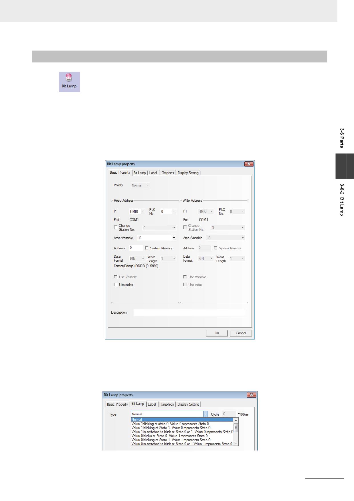
1
Drag the Bit Lamp icon after it is pressed, then the [Basic Properties] dialog box for Bit Lamp
component will pop up.
3
Read Address: Refers to the bit address controlling the displayed information (such as the state,
graphics, label and so on) of the lamp.
Address: Refers to the bit address corresponding to the lamp.
2
Switch to the [Bit Lamp] tab.
NB-series Programmable Terminals NB-Designer Operation Manual(V106)
3-85
3 Functions of NB-Designer
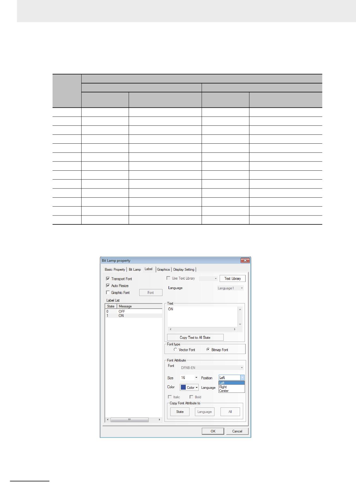
Function:
Blinking rate is set in “Cycle” box with the unit of 100 ms (If the rate is set to 500 ms, both ON time and
OFF time of the Bit Lamp are 500 ms.).
Address State of Bit to Be Read
ON (value 1)
OFF (value 0)
Function
Display
Display
State No.
State No.
(Blink/Not Blink)
(Blink/Not Blink)
1
Not Blink
1
Not Blink
0
2
Blink
0
Not Blink
0
3
Blink
1
Not Blink
0
4
Not Blink
Switching between 0 and 1
Not Blink
0
5
Not Blink
0
Blink
0
6
Not Blink
0
Blink
1
7
Not Blink
0
Not Blink
Switching between 0 and 1
8
Blink
0
Not Blink
1
9
Blink
1
Not Blink
1
10
Not Blink
Switching between 0 and 1
Not Blink
1
11
Not Blink
1
Blink
0
12
Not Blink
1
Blink
1
13
Not Blink
1
Not Blink
Switching between 0 and 1
3
Switch to the [Label] tab and add the texts corresponding to the On and Off states.
State: Off will be displayed when the lamp state is 0; while On will be displayed when the state is 1.
Alignment: Three methods are available, as shown below:
Left: The input content is put in the left side of the graphics.
3-86
NB-series Programmable Terminals NB-Designer Operation Manual(V106)
3 Functions of NB-Designer
Right: The input content is put in the right side of the graphics.
Center: The input content is put in the center of the graphics.
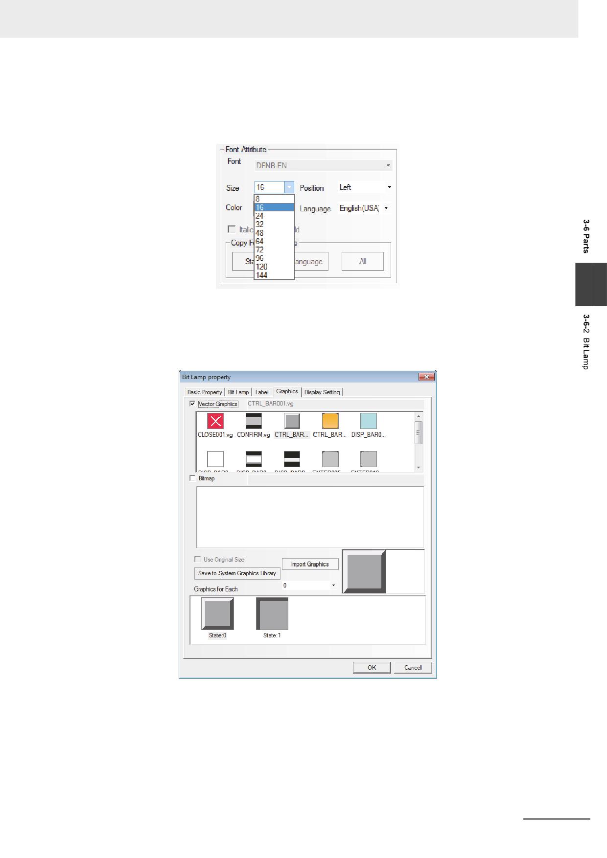
Font Size: Displays the size of the font used by the content input to “Message” and the following types
are available.
3
Color: Displays the colors of fonts used by the content input to “Message”, and the user can use
“Custom Color…” to specify the desired colors.
4
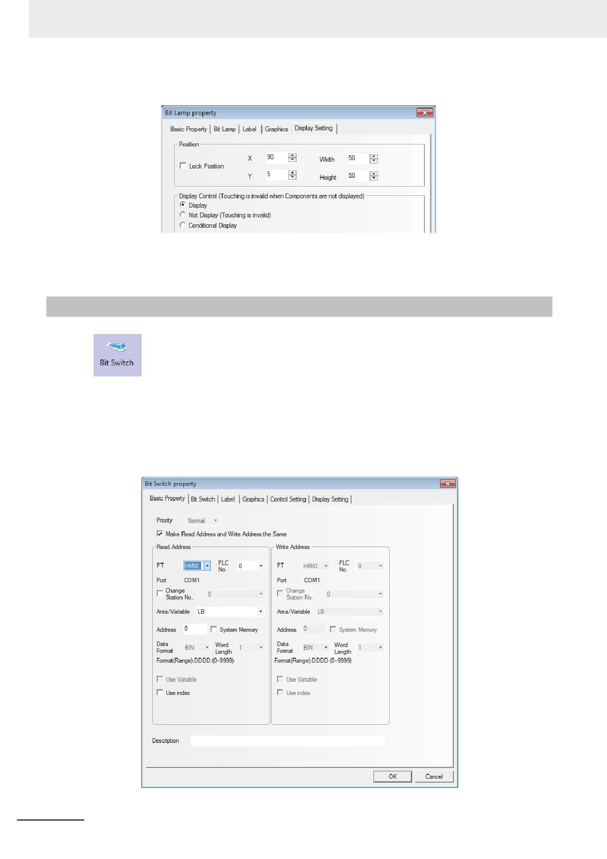
Switch to the [Graphics] tab, and select Vector Graphics or bitmap to represent the graphics
corresponding to the On and Off states of the bit address.
NB-series Programmable Terminals NB-Designer Operation Manual(V106)
3-87
3 Functions of NB-Designer
5
Switch to the [Display Setting] tab and adjust the position and size of the lamp component.
6
Press the [OK] button to complete the setup of the lamp component.
3-6-3
Bit Switch
Bit Switch is the combination of the Bit Lamp and the Bit Button component. It defines a
touching area, and the bit address inside the PT or of the PLC can be switched between On and Off
state when this area is enabled.
Process of adding one Bit Switch
1
Drag the Bit Switch icon after it is pressed, then the [Basic Properties] dialog box of Bit Switch
component will pop up.
3-88
NB-series Programmable Terminals NB-Designer Operation Manual(V106)
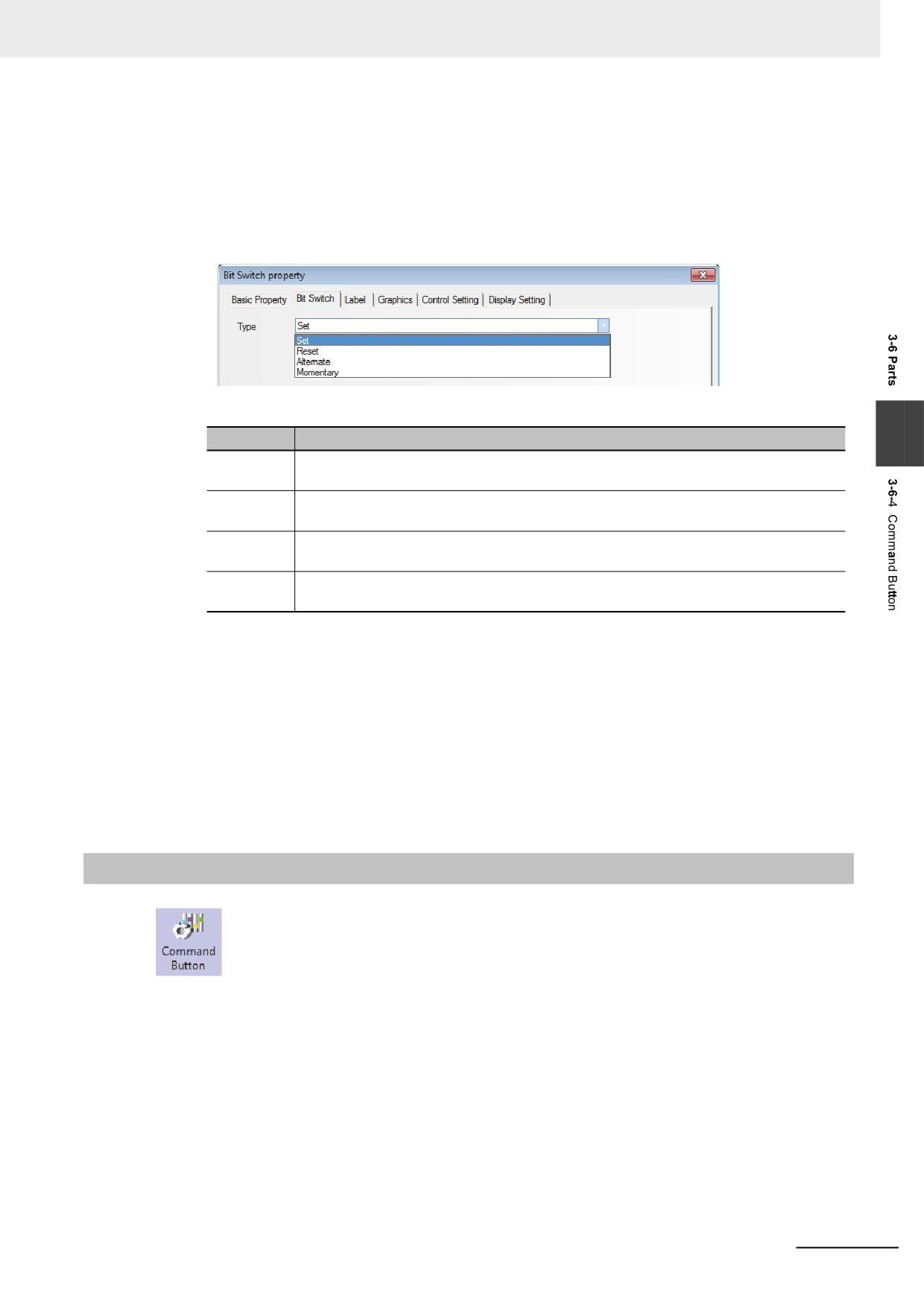
3 Functions of NB-Designer
Read Address: Bit address controls the display information of Bit Switch such as the status,
graphic, and label.
Write Address: Bit address writes the status of On or Off controlled by the Bit Switch.
Address: Refers to the Read/Write Address corresponding to the switch.
2
Switch to the [Bit Switch] tab and set switch type.
Types and Functions of Switch
3
Type
Descriptions
Set
The specified bit address will turn On when the component is pressed. The state
remains even if the component is released.
Reset
The specified bit address will turn Off when the component is pressed. The state
remains even if the component is released.
Alternate
The state of the specified bit address will change once (OnOffOn) when the
component is pressed each time.
Momentary
The specified bit address state will turn On or Off when the component is pressed or
released respectively.
3
Switch to the [Label] and add the text corresponding to the state.
4
Switch to the [Graphics] tab, and select Vector Graphics or bitmap to display the bit address
state and represent the touching area.
5
Switch to the [Control Setting] tab and make the Security Setting and set the Triggering action.
6
Press the [OK] button to complete the setup of the Bit Switch component.
3-6-4
Command Button
Command Button component also defines a touching area and the state value will be input
into the specified word address when the area is enabled.
NB-series Programmable Terminals NB-Designer Operation Manual(V106)
3-89
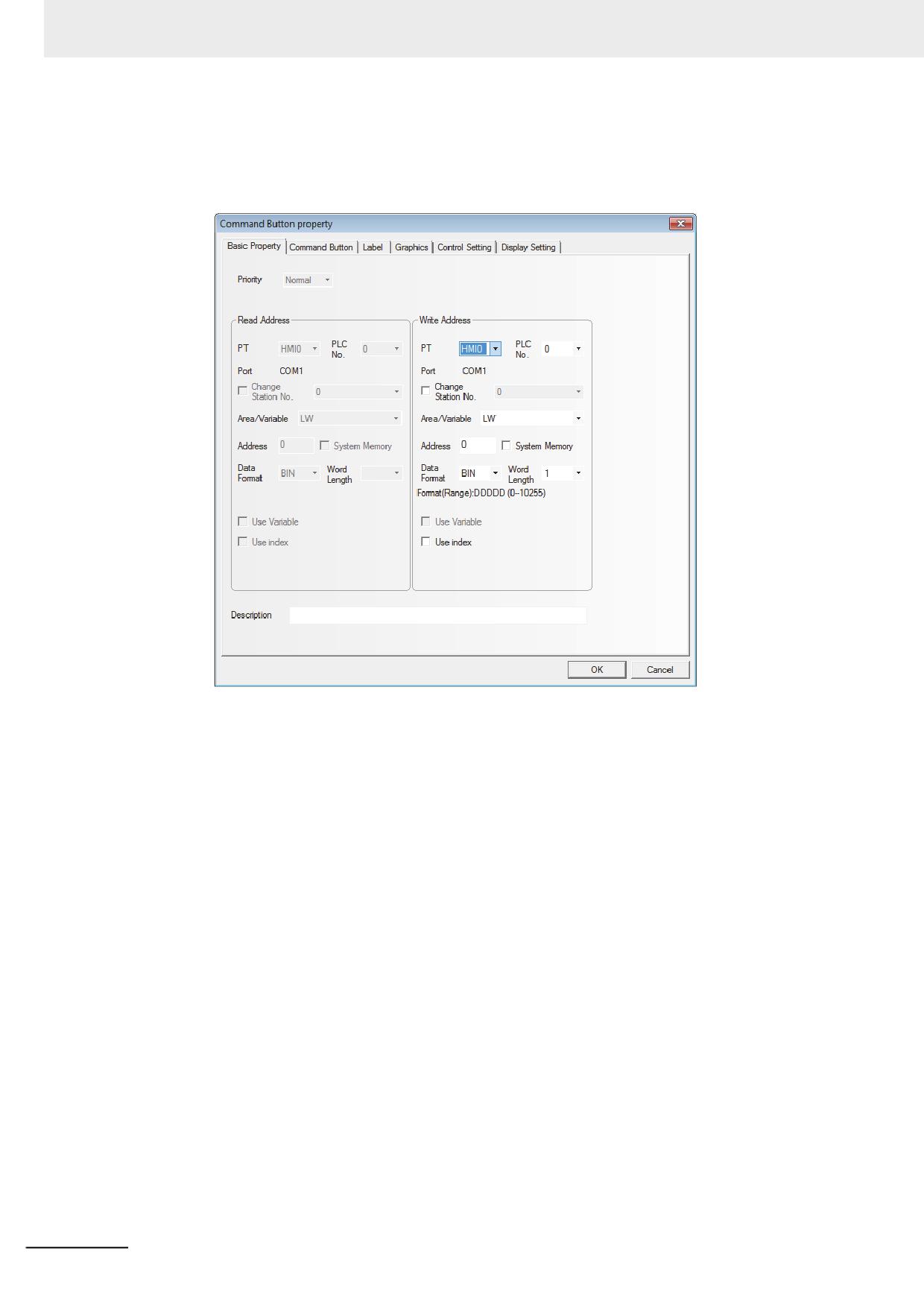
3 Functions of NB-Designer
Process of adding one Command Button component
1
Dragging the Command Button component icon after it is pressed will make the [Basic
Properties] of Command Button component pop up.
Write Address: Refers to the word address controlling the Command Button component.
Address: The first address of word address corresponding to the Command Button component.
Word Length: Set word length of the write address. Either of 1 (single word) or 2 (double words) can
be specified.
3-90
NB-series Programmable Terminals NB-Designer Operation Manual(V106)
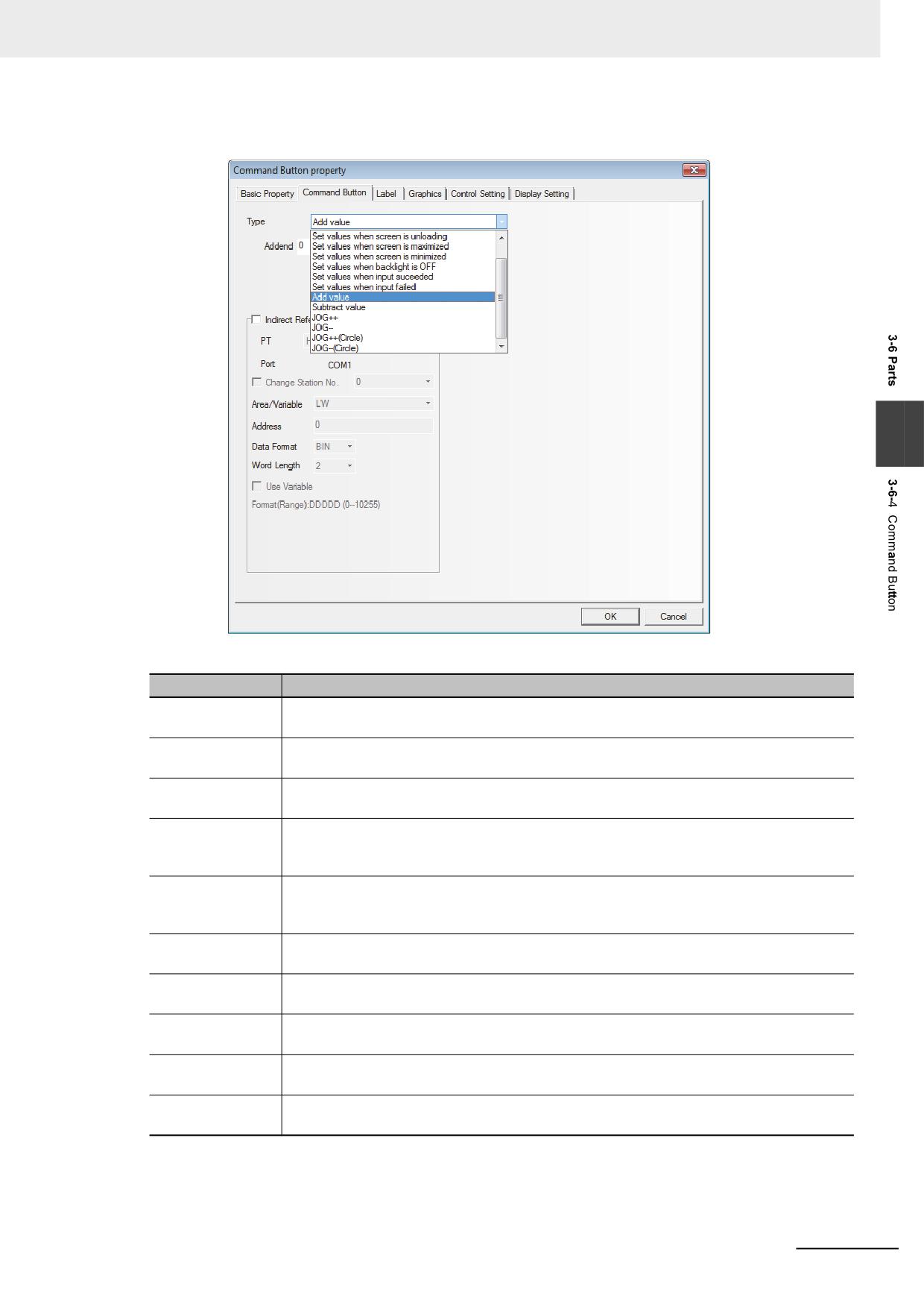
3 Functions of NB-Designer
2
Switch to the [Command Button] tab and set the “Type” for the Command Button component.
3
Setting Mode is as follows.
Type
Descriptions
Set Values
The preset constant will be written to the specified word address when this component is
pressed. *
Set values when
The preset constant will be written to the specified word address when one screen is
screen is loading
opened. *
Set values when
The preset constant will be written to the specified word address when one screen is
screen is unloading
closed. *
Set values when
The preset constant will be written to the specified word address when the screen is
screen is
maximized. *
maximized
Set values when
The preset constant will be written to the specified word address when the screen is
screen is
minimized. *
minimized
Set values when
The preset constant will be written to the specified word address when the backlight is Off. *
backlight is OFF
Set values when
The preset constant will be written to the specified word address when the number or text is
input suceeded
input successfully. (Input the constant to be set in “Set Value”.)*
Set values when
The preset constant will be written to the specified word address when the number or text is
input failed
not input successfully. *
Add value
Each time this component is pressed, the value of the specified word address will be
increased by the “Addend” once, and its result will not exceed the “Upper”.*
Subtract value
Each time this component is pressed, the value of the specified word address will subtract
the “Subtrahend” and its result will not be less than the “Upper”.*
NB-series Programmable Terminals NB-Designer Operation Manual(V106)
3-91
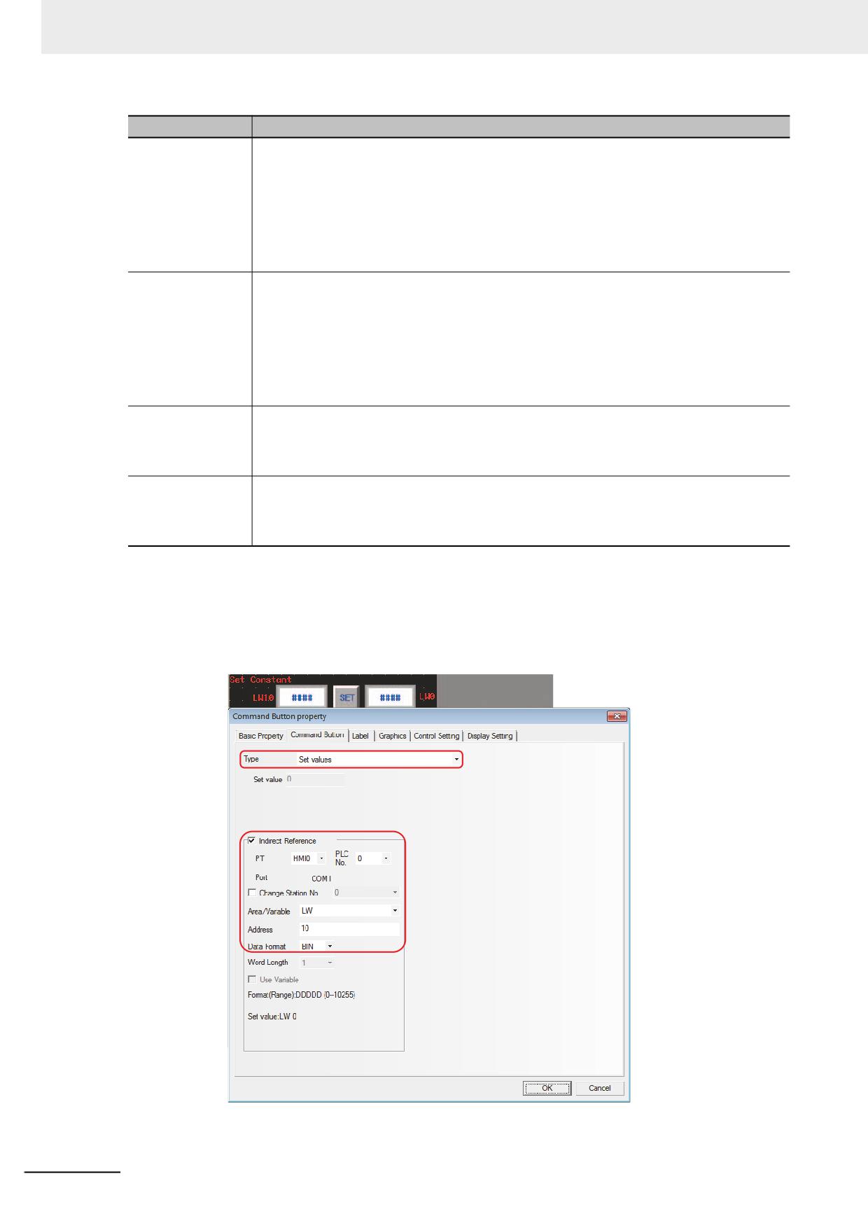
3 Functions of NB-Designer
Type
Descriptions
JOG++
Everytime command button is pressed for the time longer than the time to be specified
“Delay Time”, the value * set to “Addend” is added to the value of the write address with the
interval set to “JOG Speed”.
The result will not exceed the “Upper”. When [Ignore Delay Time] is checked, the “Addend”
will be added to the value of the specified word address immediately each time the
component is pressed. If this component is pressed for a long time, the “Addend” will be
added to the value of the specified word address at the interval of “JOG Speed” time until
the “Upper” is reached.
JOG--
Everytime command button is pressed for the time longer than the time to be specified
“Delay Time”, the value set to “Subtrahend” * is subtracted from the value of the write
address with the interval set to “JOG Speed”.
The result will not be less than the “Lower”. When [Ignore Delay Time] is checked, the
“Subtrahend” will be added to the value of the specified word address immediately each
time the component is pressed. If this component is pressed for a long time, the
“Subtrahend” will be added to the value of the specified word address at the interval of
“JOG Speed” time until the “Lower” is reached.
JOG++ (Circle)
Everytime command button is pressed for the time longer than the time to be specified
“Delay Time”, the value * set to “Addend” is added to the value of the write address with the
interval set to “JOG Speed”.
Until the “Upper” is reached, and then it will increase from the “Lower” again.
JOG--(Circle)
Everytime command button is pressed for the time longer than the time to be specified
“Delay Time”, the value * set to “Subtrahend” is subtracted from the value of the write
address with the interval set to “JOG Speed”.
Until the “Lower” is reached, and then it will decrease from the “Upper” again.
*Indirect Reference: Refers to the variables that can be used by the setting or the upper/lower limit etc.
For example:
(a) When Setting Mode is “Set Value”.
Assuming the write address of the Command Button component is LW0 with the “Type” of “Set Value”,
check [Indirect Reference] and select “LW10” as the address of variable parameter.
3-92
NB-series Programmable Terminals NB-Designer Operation Manual(V106)
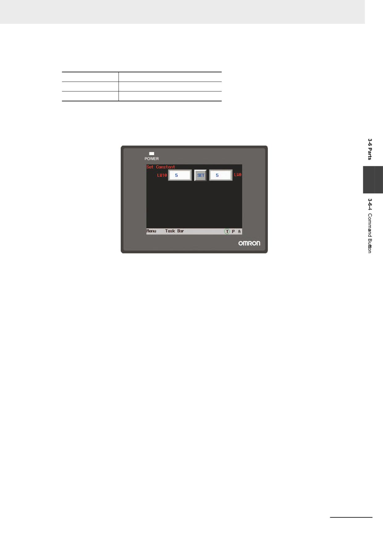
3 Functions of NB-Designer
The settable indirect reference values are single-WORD BIN or BCD values. The value range varies
depending on the selected data format.
BIN(unsigned)
0-65535
BIN(signed)
-32768 - 32767
BCD
0-9999
When LW10 is 5, it means the Set Value is 5. In this case, clicking “Set” will write the value of LW10
(i.e. 5) into LW0.
Perform the offline test and the effect is shown as below.
3
NB-series Programmable Terminals NB-Designer Operation Manual(V106)
3-93
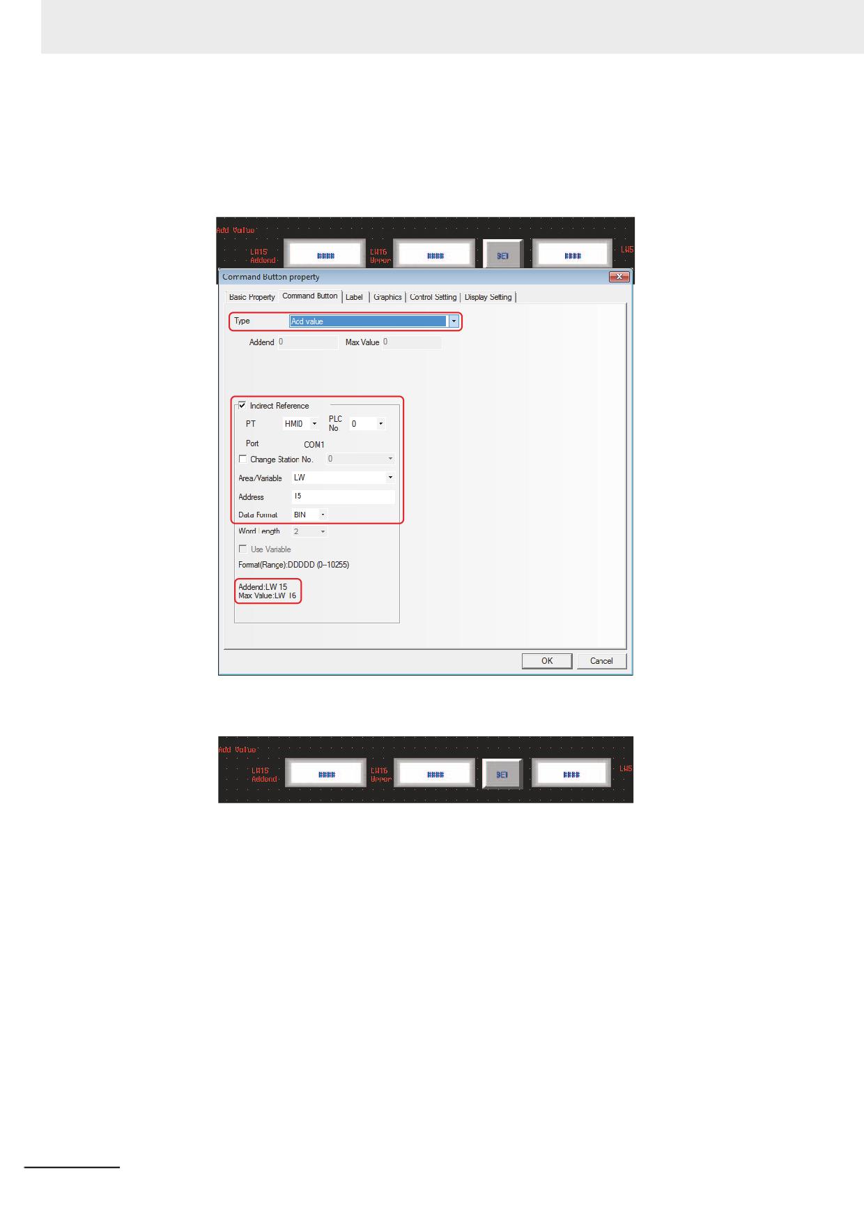
3 Functions of NB-Designer
(b) When Setting Mode is “Add value”.
Assuming the write address of the Command Button component is LW5 with “Type” of “Add value”,
check [Indirect Reference] and select “LW15” and “2” as the first address of variable parameter and the
default word length respectively. The Addend address and the Upper Limit address are set by LW15
and LW16 respectively.
In addition, place 2 Number Input components with the addresses of LW15 and LW16 respectively as
well as 1 Number Display component with the address of LW5.
When LW15 is 10 and LW16 is 100, LW5 will increase by 10 each time when “Set” is pressed until the
upper limit (i.e. 100) is reached and then stop increase.
3-94
NB-series Programmable Terminals NB-Designer Operation Manual(V106)
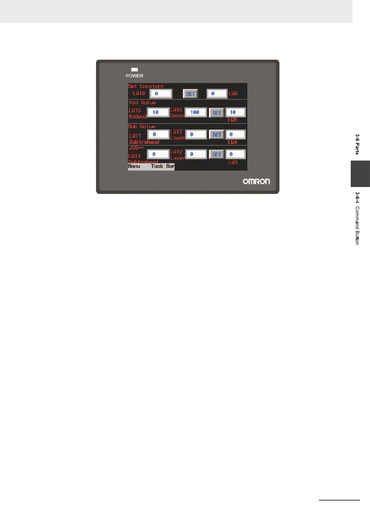
3 Functions of NB-Designer
Perform the offline test and the effect is shown as below.
3
3
Switch to the [Label] tab and add the text describing the state.
4
Switch to the [Graphics] tab and select Vector Graphics or bitmap to display the bit address
state and represent the touching area.
5
Switch to the [Control Setting] tab and make the Security Setting and set the Triggering action.
6
Press the [OK] button to complete the setup of the Command Button component.
NB-series Programmable Terminals NB-Designer Operation Manual(V106)
3-95
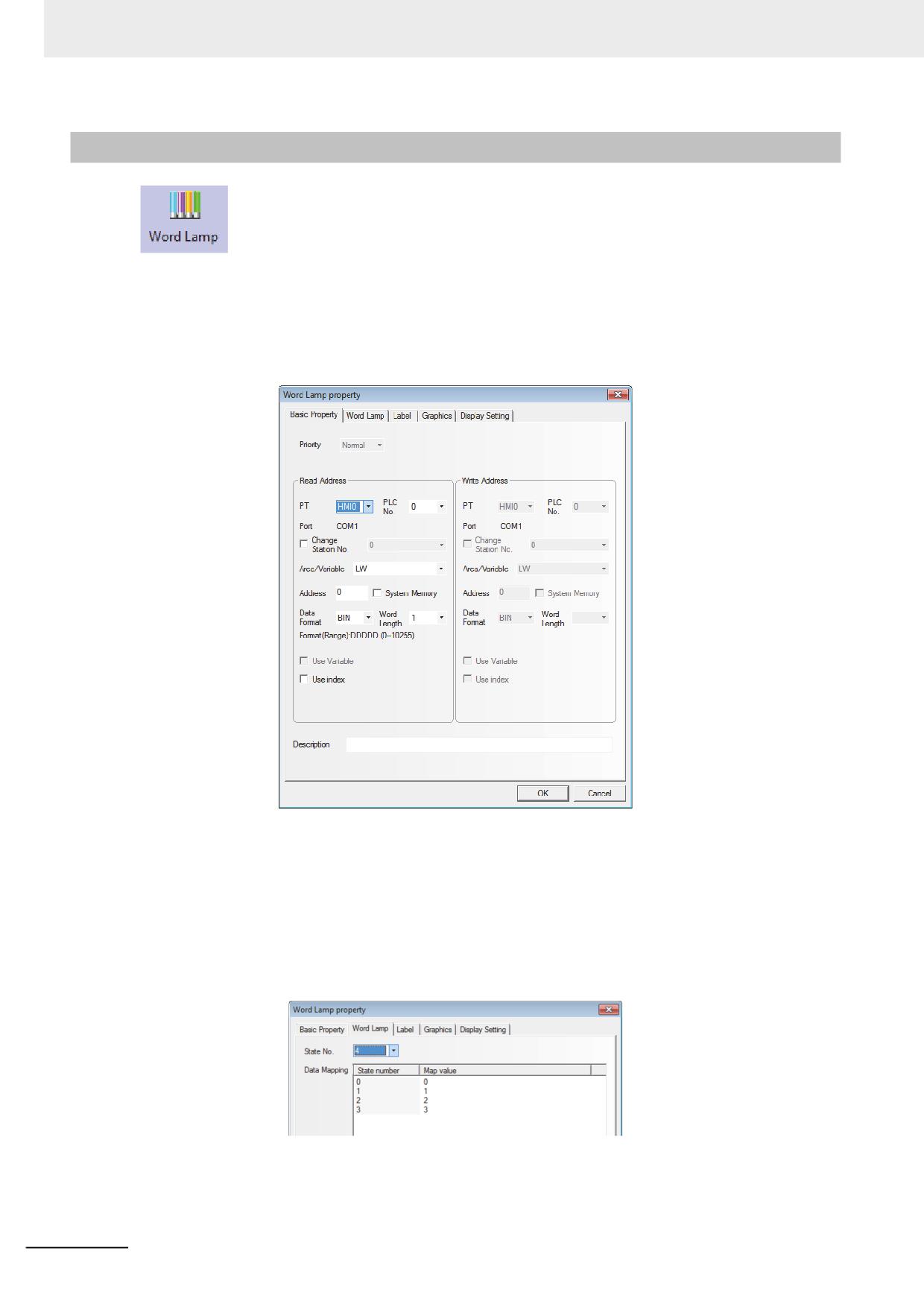
3 Functions of NB-Designer
3-6-5
Word Lamp
Word Lamp is the component which will switch the display information according to the
value of the specified word address.
Process of adding one Word Lamp component
1
Drag the Word Lamp component icon after it is pressed will make the [Basic Properties] of
Word Lamp component pop up.
Read Address: Refers to the PLC address controlling the displayed information (such as the
state, graphics, label and so on) of the Word Lamp component.
Address: The first address of word address corresponding to the Word Lamp component.
Word Length: Displays the data length of the Read Address, and 1 and 2 are available (i.e.
word or double-word).
2
Switch to the [Word Lamp] tab and set the state for the Word Lamp component. You can set
the state from 1 to 256 in the dropdown box corresponding to “State No.”.
Map Value: Refers to the value corresponding to each state. When the value of read address
is equal to the map value, the state number corresponding to this value will be displayed.
3-96
NB-series Programmable Terminals NB-Designer Operation Manual(V106)
3 Functions of NB-Designer
3
Switch to the [Label] tab and add the different displayed texts corresponding to the different
states.
4
Switch to the [Graphics] tab and select Vector Graphics or bitmap to display the graphics
corresponding to the state of the Word Lamp component.
5
Press the [OK] button to complete the setup of the Word Lamp component.
3
NB-series Programmable Terminals NB-Designer Operation Manual(V106)
3-97
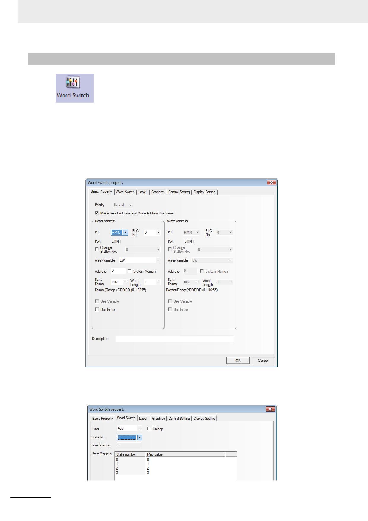
3 Functions of NB-Designer
3-6-6
Word Switch
Word Switch is the component which changes the status value of the value specified for
each status value and send the value to the specified address. The status value is changed by
increasing or decreasing for each touch operation or by selecting from the list. When changing the
status, the mapping value specified for each status will be sent to the specified memory. The statuses
can be set up to 256.
Process of adding one Word Switch component
1
Drag the Word Switch icon after it is pressed will make the [Basic Properties] of Word Switch
component pop up.
2
Switch to the [Word Switch] tab and set the State No. and the value corresponding to each
state for the component. You can set the state from 1 to 256 in the dropdown box
corresponding to “State No.”.
3-98
NB-series Programmable Terminals NB-Designer Operation Manual(V106)
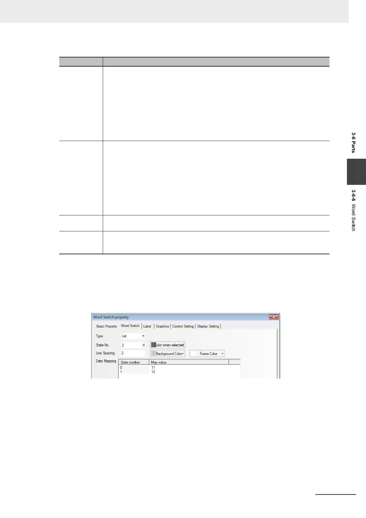
3 Functions of NB-Designer
Functions of Word Switch:
Type
Descriptions
Add
Each time this component is pressed, 1 will be added to the state number, and the map
value of the corresponding state will be written into the specified write address, and the
graphics corresponding to the state will be displayed according to the specified read
address at the same time.
Unloop: When it is checked, and the value of the memory for write address is equal to the
value mapped by the set maximum state number, the component doesn’t act when
the switch is pressed again. When it isn’t checked and the value of the memory of
write address is equal to the value mapped by the set maximum state number, the
value of the memory for write address is equal to the value mapped by the
minimum state number.
Sub
Each time this component is pressed, 1 will be subtracted from the state number, and the
map value of the corresponding state will be written into the specified write address, and
the graphics corresponding to the state will be displayed according to the specified read
address at the same time.
3
Unloop: When it is checked, and the value of the memory for write address is equal to the
value mapped by the minimum state number, the component doesn’t act when the
switch is pressed again. When it isn’t checked and the value of the memory of
write address is equal to the value mapped by the minimum state number, the
value of the memory for write address is equal to the value mapped by the set
maximum state number.
List
All the set states will be displayed in the list form, and the current state is differentiated by
the specified color.
Dropdown List
All the set states will be displayed in the dropdown list form, and the current state is
differentiated by the specified color and the first information displayed in the dropdown list
represents the current state.
For the control modes of Add and Sub, [Unloop] is not checked by default.
State No.: All 256 statuses can be set at maximum. (When BIN or BCD code and LSB code are used,
or when LSB code is used, the status of 256 (at maximum) and the status of 17 (at
maximum) will be displayed, respectively. Refer to 10 LSB Type (Page 3-378) in the section
3-16).
The line spacing for the list and the dropdown list can be set:
Map Value: When the value read by the read address is equal to a certain value in the Map Value, the
Word Switch component will display the label and the graphics corresponding to the state number of
this value. When a certain state number is switched to, the value corresponding to this value will be
written into the write address.
3
Switch to the [Label] tab and add the text corresponding to the state.
4
Switch to [Graphics] tab, and select Vector Graphics or bitmap to display the memory state and
represent the touching area.
5
Switch to the [Control Setting] tab and make the Security Setting and set the Triggering action.
NB-series Programmable Terminals NB-Designer Operation Manual(V106)
3-99
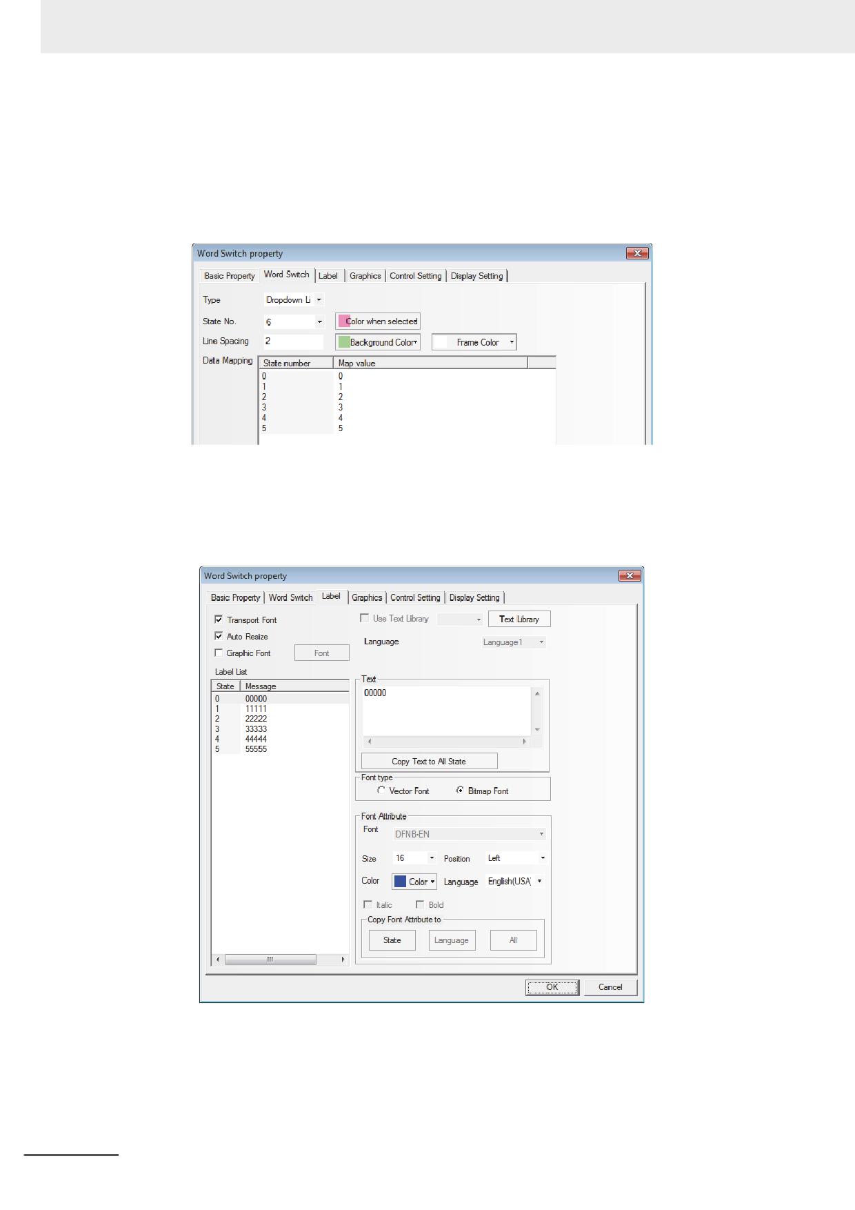
3 Functions of NB-Designer
6
Press the [OK] button to complete the setup of the Word Switch component.
List and Dropdown List
List: Refers to the value of the specified memory corresponding to the state of each option. By
default, the value of specified memory corresponding to the first option is “0”, and the value of
specified memory corresponding to the second option is “1”, and so on.
For example:
(1) Create a Word Switch in which read address and write address are LW0 and a number
display component in which address is LW0.
(2) Set the Control Mode and State No. to “List” and “6” respectively.
(3) Create the labels with the contents as shown below.
3-100
NB-series Programmable Terminals NB-Designer Operation Manual(V106)