Design Principles High-speed Maglev System. Information (MSB, 2007) - page 12

High-speed maglev systems
Maglev Technical Committee
Design principles
Guideway
Annex II-B: Calculated vibration coefficients
General
(1)
The examples of the vibration coefficient diagrams given below include the global vibration coefficient
ϕBg,z or ϕBg,z,WSE for simple beams with spans LSt = 12.384 m and LSt = 24.768 m. This coefficient is not
dependent on the structural design or the construction method. In this regard, the vibration coefficients
indicate the dynamic camber as a result of the effects of the moved vehicle in the z direction.
(2)
Using the example of the loads E in the centre of the girder (e.g. deflection, internal forces, stresses),
the diagrams below show how the load develops over time in principle as a result of a vehicle passing
over and the associated assessment variables.
E
Fig. 161 - Passage of the vehicle along the simple beam with the assessment variable w in the midspan
E(t)
max Edyn
∆E-
max ∆E
dyn
max Estat
min Edyn
Fig. 162 - Load development over time as a result of a vehicle passing along the simple beam
Title
High-speed Maglev Systems - Design principles
Guideway - Part II: Design
Doc. no.:
57288
Version
White Paper Issue date
15.02.2007
Page 130
High-speed maglev systems
Maglev Technical Committee
Design principles
Guideway
(3)
Idealised mathematical models form the basis of the diagrams. These diagrams consider the dynamic
cambers as a result of period and harmonic stimulations (“Impact" and “Resonance”); cf. in this regard
R2, R3 and R4.
(4)
The following parameters form the basis of the diagrams:
• Span, simple beam, where:
LSt = 12.384 m and LSt = 24.768 m
• Vehicle lengths:
2; 4; 6; 10 sections
• Damping factor D:
0%; 0.3%; 0.6%; 1.6%
• Vehicle load scenarios:
as per Chapter 9
(5)
The following assessment variables are also covered by the diagrams:
• Deflection
max/min wdyn
• Bending moment
max/min My,dyn
• Shearing load
max/min Vz,dyn
(6)
The diagrams were prepared in relation to furnishing the following proof:
• The vibration coefficient for furnishing proof of performance capability and loadbearing capacity
max E
dyn
ϕ
=
Bg,z
max E
stat
• The vibration coefficient for furnishing proof of metal fatigue for determining the maximum load
amplitude:
(
max E
−min E
)
dyn
dyn
ϕ
=
Bg,z,WSE
max E
stat
(7)
The vibration coefficients are read off using the non-dimensional value k in the diagrams. The value k
is established as follows depending on the span LSt, the speed of the vehicle vFzg and the first vertical
natural bending frequency fz,1 of the support structure:
L
St
k
=
⋅
f
z,1
v
Fzg
Area of application
(1)
When using vibration coefficient diagrams (figs. 164 to 179), the following area of application must be
considered:
• a span which is approximately equal to the system length LSt ≈ LSys;
• girder-like, rigidly supported simple beams with an approximately constant weight per unit area µ
and flexural strength EI;
• with an approximately rigid connection (GAV → ∞);
• specification of the damping (damping factor D = 0%; 0.3%; 0.6%; 1.6%);
(for values in-between, the next smallest damping factor should conservatively be specified.)
• vehicle load scenarios as per Chapter 9;
• magnet end poles of the levitation magnets shall carry at least 25% of the main magnet pole
loads;
• calculation only for vertical components of the effects arising from the vehicle, globally in the z di-
rection;
• application to deflection w, the bending moment My and the shearing load Vz;
• the diagrams do not generally apply to vehicle speeds where the vehicle - guideway interaction as
a result of magnet control must be considered (low vehicle speeds vFzg < 50 m/s), and especially
not to stationary vehicles vFzg = 0 m/s.
Title
High-speed Maglev Systems - Design principles
Guideway - Part II: Design
Doc. no.:
57288
Version
White Paper Issue date
15.02.2007
Page 131
High-speed maglev systems
Maglev Technical Committee
Design principles
Guideway
(2)
The vibration coefficients for metal fatigue ϕBg,z,WSE assist in determining the maximum load amplitude
max ∆Edyn = ϕBg,z,WSE ⋅ max Estat = max Edyn - min Edyn, which shall only be specified once per vehicle
crossing.
When specifying a single-stage unit, it must be examined whether the existing double amplitudes of the load
progression are below the cut-off limit as a result of vibrations ∆Edyn. This is satisfied as long as the following
applies to ∆Edyn:
∆E
=
2
⋅γ
⋅
max E
⋅
(ϕ
−
1)
< ∆E
/
γ
dyn
Fl
stat
Bg,z
cut-off−limit
Mf
If this condition is not satisfied, and for materials or fatigue details without a “cut off limit” area, these oscilla-
tion amplitudes must also be considered in the metal fatigue proofs.
Examples of application
(1)
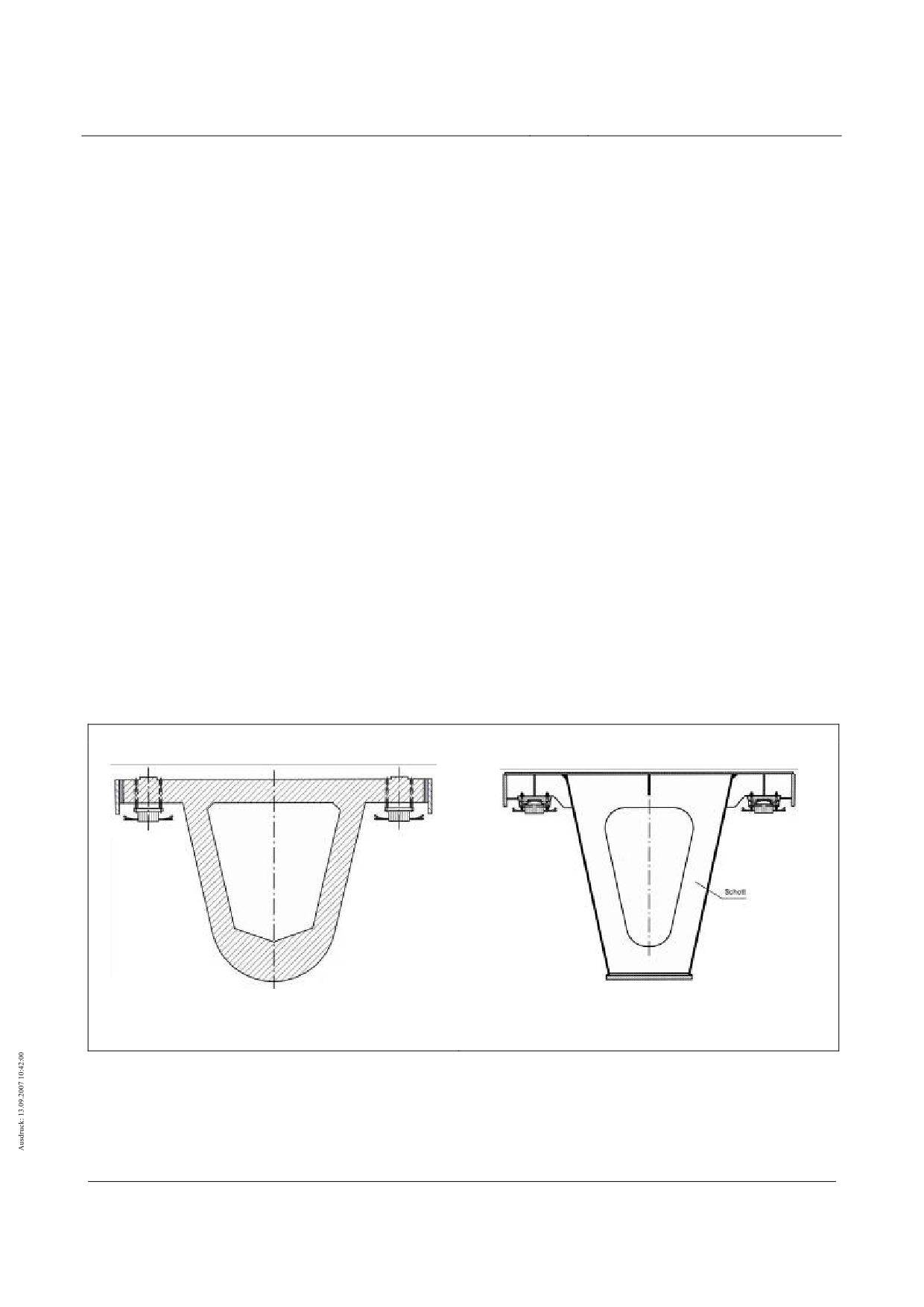
To illustrate the application of the vibration coefficient diagrams, examples are cited below of type I
support structures which are constructed in concrete or steel.
(2)
The following parameters form the basis of the examples:
• cross-sections in the panel area as per fig. 163;
• data concerning the rigidity EI and the weight per unit area µ from R1;
• simple beams with a span of LSt = 24.768 m;
• a damping factor of D = 0.6% for prestressed concrete girders;
• a damping factor of D = 0.3% for welded steel girders;
• a vehicle length consisting of 4 sections;
• max vFzg = 450 km/h = 125 m/s;
Type I, concrete construction
Type I, steel construction
EIy = 18800 MNm2
EIy = 23200 MNm2
µ = 3900 kg/m
µ = 2000 kg/m
Fig. 163 - Support structures for the example of application - cross-sections in the panel area
[Key to diagram:
Schott = bulkhead]
Title
High-speed Maglev Systems - Design principles
Guideway - Part II: Design
Doc. no.:
57288
Version
White Paper Issue date
15.02.2007
Page 132
High-speed maglev systems
Maglev Technical Committee
Design principles
Guideway
(3)
Determining the k values for reading off the global vibration coefficients from the diagrams
• As regards the Type 1 concrete construction support structure:
10
π
1,88⋅10
L
⋅f
24,768⋅5,62
St
z,1
f
=
⋅
=
5,62 Hz
→
k
=
=
=1,11
z,1
2
2⋅24,768
3900
v
125
Fzg
⇒ from fig. 174:
ϕ
Bg,z
=1,15
+1,0⋅(1,4
-k)=1,44
⇒ from fig. 175:
ϕ
Bg,z,WSE
=1,8
• As regards the Type 1 steel construction support structure:
10
π
2,32⋅10
24,768⋅8,72
f
=
⋅
=
8,72 Hz
→
k
=
=1,73
z,1
2
2⋅24,768
2000
125
⇒ from fig. 174:
ϕ
= 1,15
Bg,z
⇒ from fig. 175:
ϕ
= 1,3
Bg,z,WSE
(4)
When choosing the damping factor, Chapter 7.4.3 must be taken into consideration.
(5)
The actual (measured) natural frequencies may deviate from the natural frequencies which have been
calculated. The other results shall then be adapted accordingly.
Examples of vibration coefficient diagrams
General
(1)
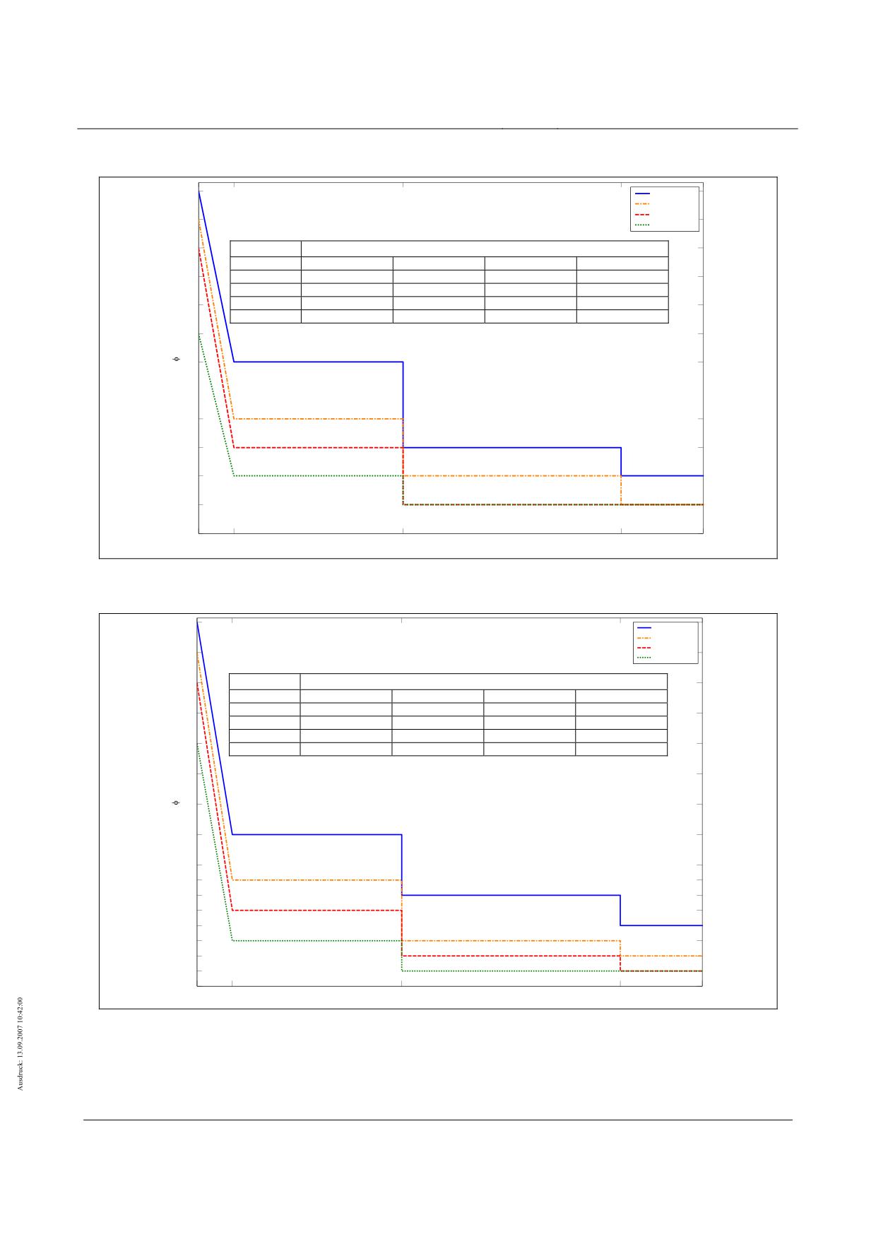
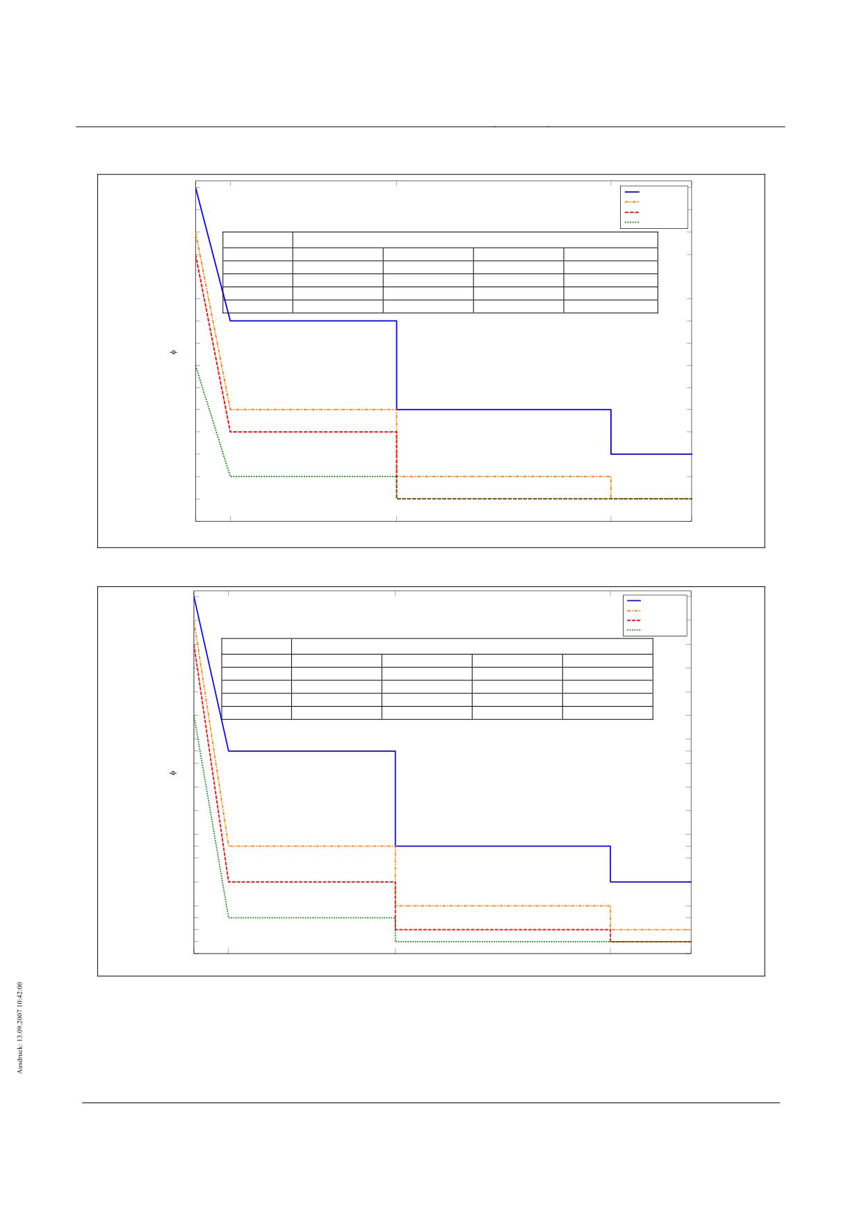
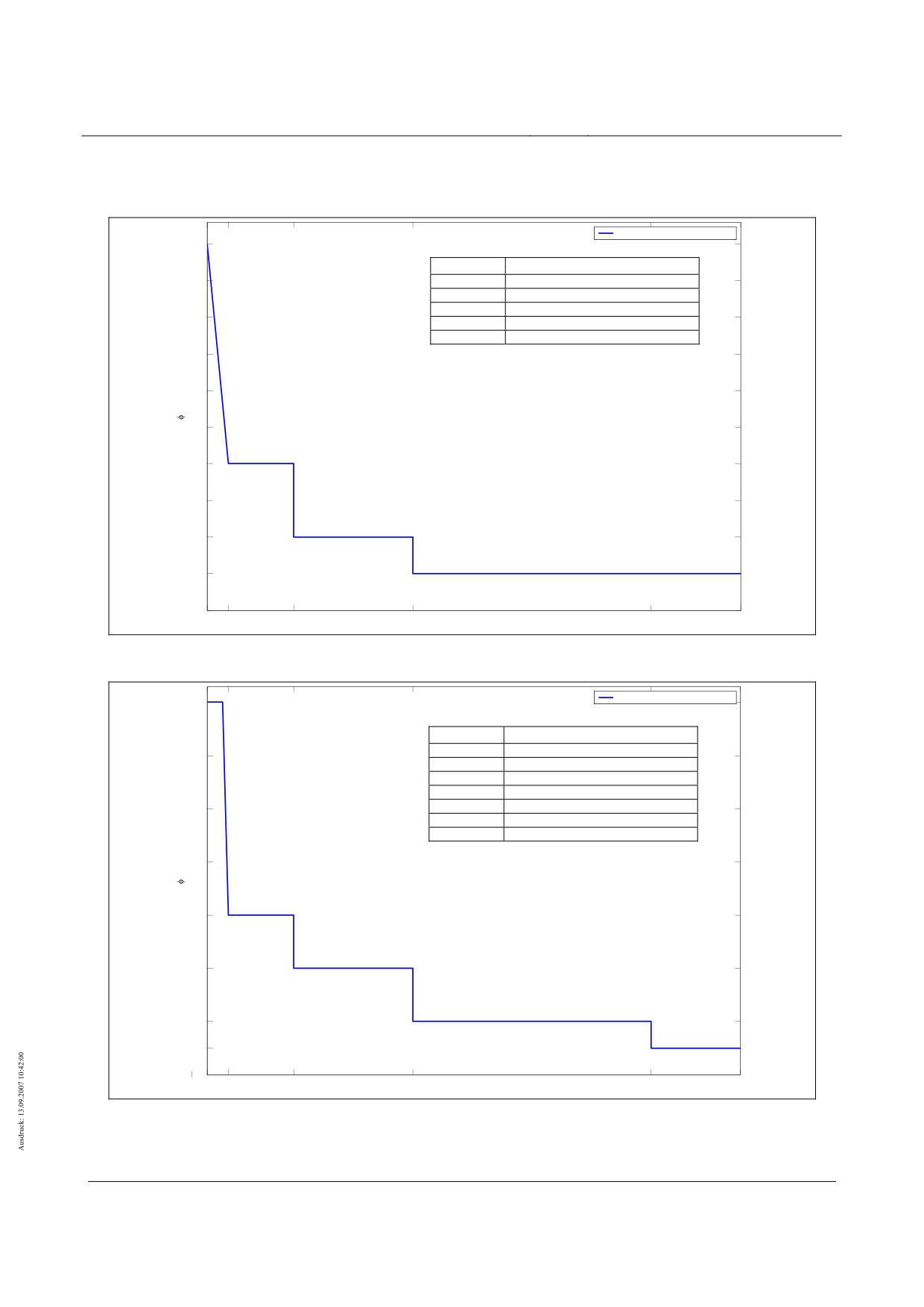
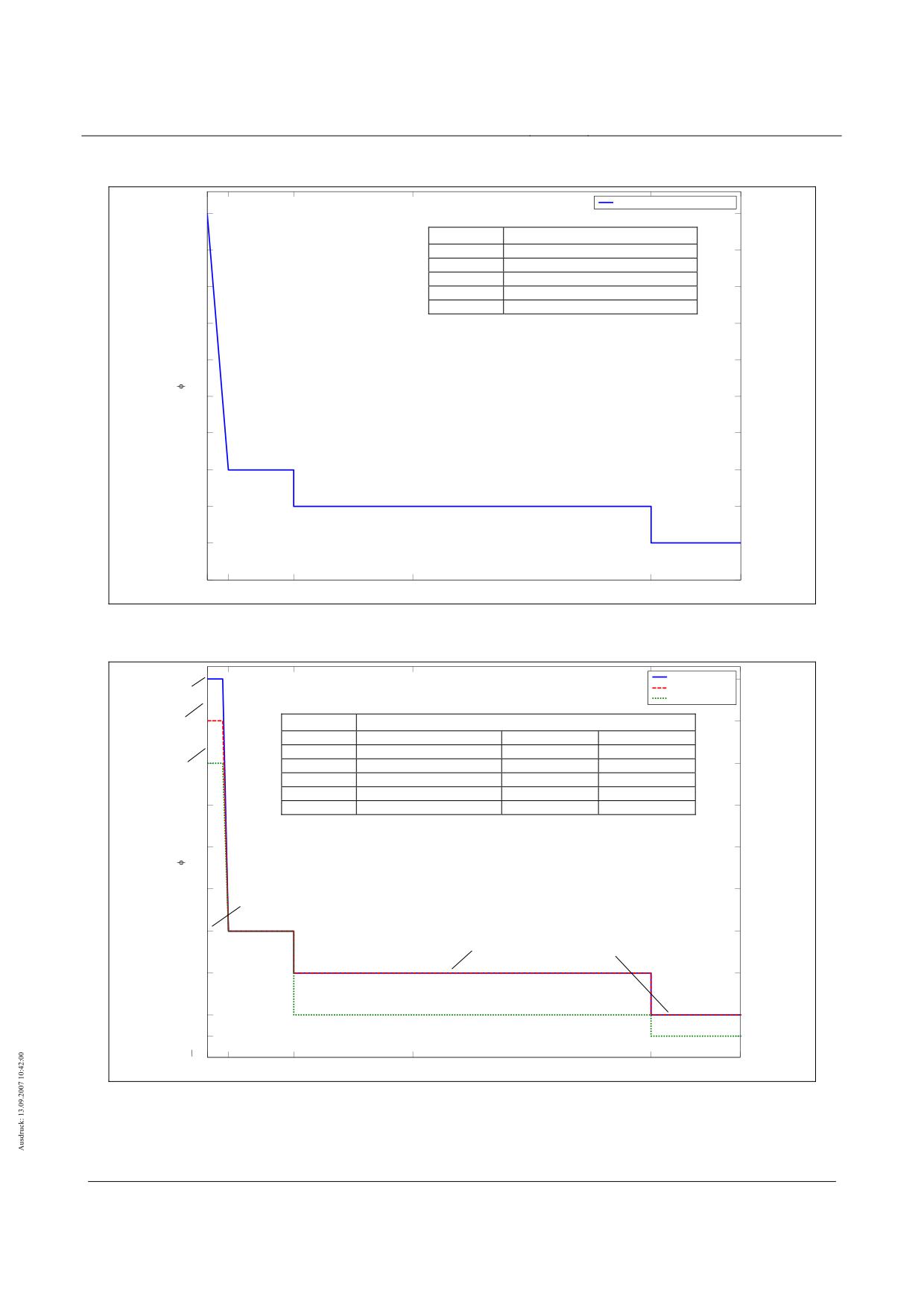
The following diagrams present examples of the vibration coefficients ϕBg,z and ϕBg,z,WSE in relation to
the spans and vehicle lengths listed in Table 116.
(2)
As a result of the investigations in R2, R3 and R4, vibration coefficient calculation lines were deter-
mined in relation to different areas of k and the damping values analysed which take into account the
dynamic cambers as a result of period and harmonic stimulation following a vehicle crossing.
Span
Vehicle length
Page
2 sections
Figs. 164 and 165
4 sections
Figs. 166 and 167
LSt = 12.384 m
6 sections
Figs. 168 and 169
10 sections
Figs. 170 and 171
2 sections
Figs. 172 and 173
4 sections
Figs. 174 and 175
LSt = 24.768 m
6 sections
Figs. 176 and 177
10 sections
Figs. 178 and 179
Table 116 - Spans and vehicle lengths of the vibration coefficient diagrams provided by way of example
Title
High-speed Maglev Systems - Design principles
Guideway - Part II: Design
Doc. no.:
57288
Version
White Paper Issue date
15.02.2007
Page 133
High-speed maglev systems
Maglev Technical Committee
Design principles
Guideway
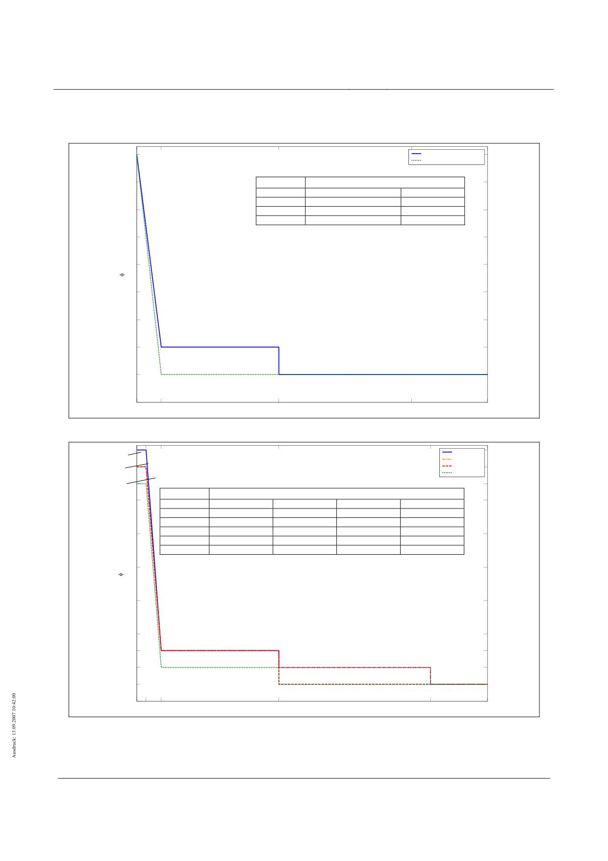
Vibration coefficient diagrams for simple beams where LSt = 12.384 m
Vibration coefficients for 2-section vehicles
D = 0 %; 0,3 %; 0,6 %
1.9
1.9
D = 1,6 %
1.8
ϕBg,z
1.8
k
D = 0%; 0.3%; 0.6%
D = 1.6%
0.75 ≤ k ≤ 1.4
1.2 + 1.077 (1.4-k)
1.1 + 1.231 (1.4-k)
1.7
1.4 < k ≤ 4.5
1.2
1.1
1.7
4.5 < k < ∞
1.1
1.1
1.6
1.6
1.5
1.5
1.4
1.4
1.3
1.3
D = 0%; 0.3%; 0.6%
1.2
1.2
D = 1.6%
D = 0%; 0.3%; 0.6%; 1.6%
1.1
1.1
1
0.75
1.4
4.5
8
10
k [-]
Fig. 164 - ϕBg,z for simple beams where LSt = 12.384 m - 2-section vehicle
2.5
2.5
D = 0%
D = 0 %
D = 0,3 %
2.4
D = 0.3%, 0.6%
2.4
D = 1,6 %
D = 1.6%
2.3
2.3
ϕBg,z,WSE
2.2
2.2
k
D = 0%
D = 0.3%
D = 0.6%
D = 1.6%
0.75 ≤ k ≤ 1.0
2.5
2.4
2.4
2.3
1.0 ≤ k ≤ 1.4
1.3 + 3.0 (1.4-k)
1.3 + 2.75 (1.4-k)
1.3 + 2.75 (1.4-k)
1.2 + 2.75 (1.4-k)
2
1.4 < k ≤ 4.5
1.3
1.3
1.3
1.2
2
4.5 < k ≤ 8.5
1.2
1.2
1.1
1.1
8.5 < k < ∞
1.1
1.1
1.1
1.1
1.8
1.8
1.6
1.6
1.4
1.4
D = 0%, 0.3%, 0.6%
1.3
1.3
D = 1.6%
D = 0%, 0.3%
1.2
1.2
D = 0.6%, 1.6%
D =
0% - 1.6%
1.1
1.1
1
1
0.75 1
1.4
4.5
8.5
10
k [-]
Fig. 165 - ϕBg,z, WSE for simple beams where LSt = 12.384 m - 2-section vehicle
Title
High-speed Maglev Systems - Design principles
Guideway - Part II: Design
Doc. no.:
57288
Version
White Paper Issue date
15.02.2007
Page 134
High-speed maglev systems
Maglev Technical Committee
Design principles
Guideway
Vibration coefficients for 4-section vehicles
2
D = 0 %2
D = 0,3 %
D = 0,6 %
1.9
D = 1,61.9
ϕBg,z
1.8
k
D = 0%
D = 0.3%; 0.6%
D = 1.6%
1.8
075 ≤ k ≤ 1.4
1.4 + 0.923 (1.4-k)
1.3 + 0.923 (1.4-k)
1.2 + 0.769 (1.4-k)
1.4 < k ≤ 4.5
1.4
1.3
1.2
1.7
1.7
4.5 < k ≤ 8.5
1.2
1.1
1.1
8.5 < k < ∞
1.1
1.1
1.1
1.6
1.6
D = 0%
1.4
1.4
D = 0.3%; 0.6%
1.3
1.3
D =1.6%
D = 0%
1.2
1.2
D = 0.3%; 0.6%; 1.6%
D =
0% - 1.6%
1.1
1.1
1
1
0.75
1.4
4.5
8.5
10
k [/]
Fig. 166 - ϕBg,z for simple beams where LSt = 12.384 m - 4-section vehicle
3
D = 0 %
3
D = 0,3 %
D = 0,6 %
D = 1,6 %
2.8
2.8
ϕBg,z,WSE
2.6
k
D = 0%
D = 0.3%
D = 0.6%
D = 1.6%
2.6
0.75 ≤ k ≤ 1.4
1.7 + 2.0 (1.4-k)
1.6 + 1.846 (1.4-k)
1.5 + 2.0 (1.4-k)
1.3 + 2.0 (1.4-k)
1.4 < k ≤ 4.5
1.7
1.6
1.5
1.3
2.4
4.5 < k ≤ 8.5
1.4
1.2
1.2
1.1
2.4
8.5 < k < ∞
1.2
1.1
1.1
1.1
2.2
2.2
2
2
1.8
1.8
D = 0%
1.7
1.7
D = 0.3%
1.6
1.6
D = 0.6%
1.5
1.5
1.4
1.4
D = 1.6%
1.3
1.3
D = 0.3%, 0.6%
D = 0%
1.2
1.2
D =
0.3% - 1.6%
1.1
1.1
1
1
0.75
1.4
4.5
8.5
10
k [-]
Fig. 167 - ϕBg,z, WSE for simple beams where LSt = 12.384 m - 4-section vehicle
Title
High-speed Maglev Systems - Design principles
Guideway - Part II: Design
Doc. no.:
57288
Version
White Paper Issue date
15.02.2007
Page 135
High-speed maglev systems
Maglev Technical Committee
Design principles
Guideway
Vibration coefficients for 6-section vehicles
2.2
D = 0 %2.2
D = 0,3 %
2.1
D = 0,6 %
2.1
D = 1,6 %
2
ϕBg,z
2
k
D = 0%
D = 0.3%
D = 0.6%
D = 1.6%
1.9
0.75 ≤ k ≤ 1.4
1.6 + 0.923 (1.4-k)
1.4 + 1.077 (1.4-k)
1.3 + 1.077 (1.4-k)
1.2 + 0.769 (1.4-k)
1.9
1.4 < k ≤ 4.5
1.6
1.4
1.3
1.2
1.8
4.5 < k ≤ 8.5
1.3
1.2
1.1
1.1
1.8
8.5 < k < ∞
1.2
1.1
1.1
1.1
1.7
1.7
D = 0%
1.6
1.6
D = 0.3%
1.4
1.4
1.3
D = 0.6%
D = 0%
1.3
D = 1.6%
D = 0.3%
D
= 0%
1.2
1.2
D = 0.6%; 1.6%
D =
0.3% - 1.6%
1.1
1.1
1
1
0.75
1.4
4.5
8.5
10
k [/]
Fig. 168 - ϕBg,z for simple beams where LSt = 12.384 m - 6-section vehicle
3.4
3.4
D = 0 %
D = 0,3 %
D = 0,6 %
3.2
3.2
D = 1,6 %
3
ϕBg,z,WSE
3
k
D = 0%
D = 0.3%
D = 0.6%
D = 1.6%
2.8
0.75 ≤ k ≤ 1.4
2.0 + 2.154 (1.4-k)
1.7 + 2.308 (1.4-k)
1.5 + 2.308 (1.4-k)
1.3 + 2.0 (1.4-k)
2.8
1.4 < k ≤ 4.5
2.0
1.7
1.5
1.3
4.5 < k ≤ 8.5
1.6
1.3
1.2
1.1
2.6
2.6
8.5 < k < ∞
1.4
1.2
1.1
1.1
2.4
2.4
2.2
2.2
D = 0%
2
2
1.8
1.8
D = 0.3%
1.7
1.7
D = 0%
1.6
1.6
D = 0.6%
1.5
1.5
D = 0%
1.4
1.4
D = 1.6%
D = 0.3%
1.3
1.3
D = 0.6%
D = 0.3%
1.2
1.2
D = 1.6%
D = 0.6% - 1.6%
1.1
1.1
1
1
0.75
1.4
4.5
8.5
10
k [-]
Fig. 169 - ϕBg,z, WSE for simple beams where LSt = 12.384 m - 6-section vehicle
Title
High-speed Maglev Systems - Design principles
Guideway - Part II: Design
Doc. no.:
57288
Version
White Paper Issue date
15.02.2007
Page 136
High-speed maglev systems
Maglev Technical Committee
Design principles
Guideway
Vibration coefficients for 10-section vehicles
2.5
2.5
D = 0 %
D = 0,3 %
2.4
D = 0,62.4
D = 1,6 %
2.3
2.3
ϕBg,z
2.2
k
D = 0%
D = 0.3%
D = 0.6%
D = 1.6%
2.2
0.75 ≤ k ≤ 1.4
1.9 + 0.923 (1.4-k)
1.5 + 1.231 (1.4-k)
1.4 + 1.231 (1.4-k)
1.2 + 0.769 (1.4-k)
1.4 < k ≤ 4.5
1.9
1.5
1.4
1.2
4.5 < k ≤ 8.5
1.5
1.2
1.1
1.1
2
2
8.5 < k < ∞
1.3
1.1
1.1
1.1
1.9
1.9
1.8
1.8
1.7
1.7
1.6
1.6
1.5
D = 0.3%
D = 0%
1.5
1.4
D = 0.6%
1.4
1.3
1.3
1.2
D =1.6%
D = 0.3%
1.2
1.1
D = 0.6%; 1.6%
D = 0.3% - 1.6%
1.1
1
0.75
1.4
4.5
8.5
1
10
k [/]
Fig. 170 - ϕBg,z for simple beams where LSt = 12.384 m - 10-section vehicle
4
D = 0 %
4
D = 0,3 %
3.8
D = 0,63.
8
D = 1,6 %
3.6
ϕBg,z,WSE
3.6
k
D = 0%
D = 0.3%
D = 0.6%
D = 1.6%
3.4
3.4
0.75 ≤ k ≤ 1.4
2.7 + 2.0 (1.4-k)
1.9 + 2.923 (1.4-k)
1.6 + 3.077 (1.4-k)
1.3 + 2.615 (1.4-k)
1.4 < k ≤ 4.5
2.7
1.9
1.6
1.3
3.2
3.2
4.5 < k ≤ 8.5
1.9
1.4
1.2
1.1
3
8.5 < k < ∞
1.6
1.2
1.1
1.1
3
2.8
2.8
2.7
2.7
2.6
2.6
2.4
2.4
2.2
2.2
2
2
D = 0.3%
D = 0%
1.9
1.9
1.8
1.8
D = 0.6%
1.6
1.6
D = 0.3%
1.4
1.4
D = 1.6%
1.3
1.3
D = 0.6%
D = 0.3%
1.2
1.2
1.1
D = 1.6%
D =
0.6% - 1.6%
1.1
1
0.75
1.4
4.5
8.5
1
10
k [-]
Fig. 171 - ϕBg,z, WSE for simple beams where LSt = 12.384 m - 10-section vehicle
Title
High-speed Maglev Systems - Design principles
Guideway - Part II: Design
Doc. no.:
57288
Version
White Paper Issue date
15.02.2007
Page 137
High-speed maglev systems
Maglev Technical Committee
Design principles
Guideway
Vibration coefficient diagrams for simple beams where LSt = 24.768 m
Vibration coefficients for 2-section vehicles
D = 0 %, 0,3 %, 0,6 %, 1,6 %
1.5
1.5
ϕBg,z
1.45
k
D = 0%; 0.3%; 0.6%; 1.6%
1.45
1.05 ≤ k ≤ 1.4
1.2 + 0.857 (1.4-k)
1.4 < k ≤ 2.5
1.2
1.4
1.4
2.5 < k ≤ 4.5
1.1
4.5 < k < ∞
1.05
1.35
1.35
1.3
1.3
1.25
1.25
1.2
1.2
1.15
1.15
1.1
1.1
D = 0%; 0.3%; 0.6%; 1.6%
1.05
1.05
1
1.05
1.4
2.5
4.5
8.5
1
10
k [-]
Fig. 172 - ϕBg,z for simple beams where LSt = 24.768 m - 2-section vehicle
D = 0 %, 0,3 %, 0,6 %, 1,1.7
1.7
ϕBg,z,WSE
k
D = 0%; 0.3%; 0.6%; 1.6%
1.6
1.6
1.05 ≤ k ≤ 1.3
1.7
1.3 ≤ k ≤ 1.4
1.3 + 4.0 (1.4-k)
1.4 < k ≤ 2.5
1.3
1.5
2.5 < k ≤ 4.5
1.2
1.5
4.5 < k ≤ 8.5
1.1
8.5 < k < ∞
1.05
1.4
1.4
1.3
1.3
1.2
1.2
D = 0%; 0.3%; 0.6%; 1.6%
1.1
1.1
1.05
1.05
1
1.05
1.4
2.5
4.5
8.5
1
10
1.3
k [-]
Fig. 173 - ϕBg,z, WSE for simple beams where LSt = 24.768 m - 2-section vehicle
Title
High-speed Maglev Systems - Design principles
Guideway - Part II: Design
Doc. no.:
57288
Version
White Paper Issue date
15.02.2007
Page 138
High-speed maglev systems
Maglev Technical Committee
Design principles
Guideway
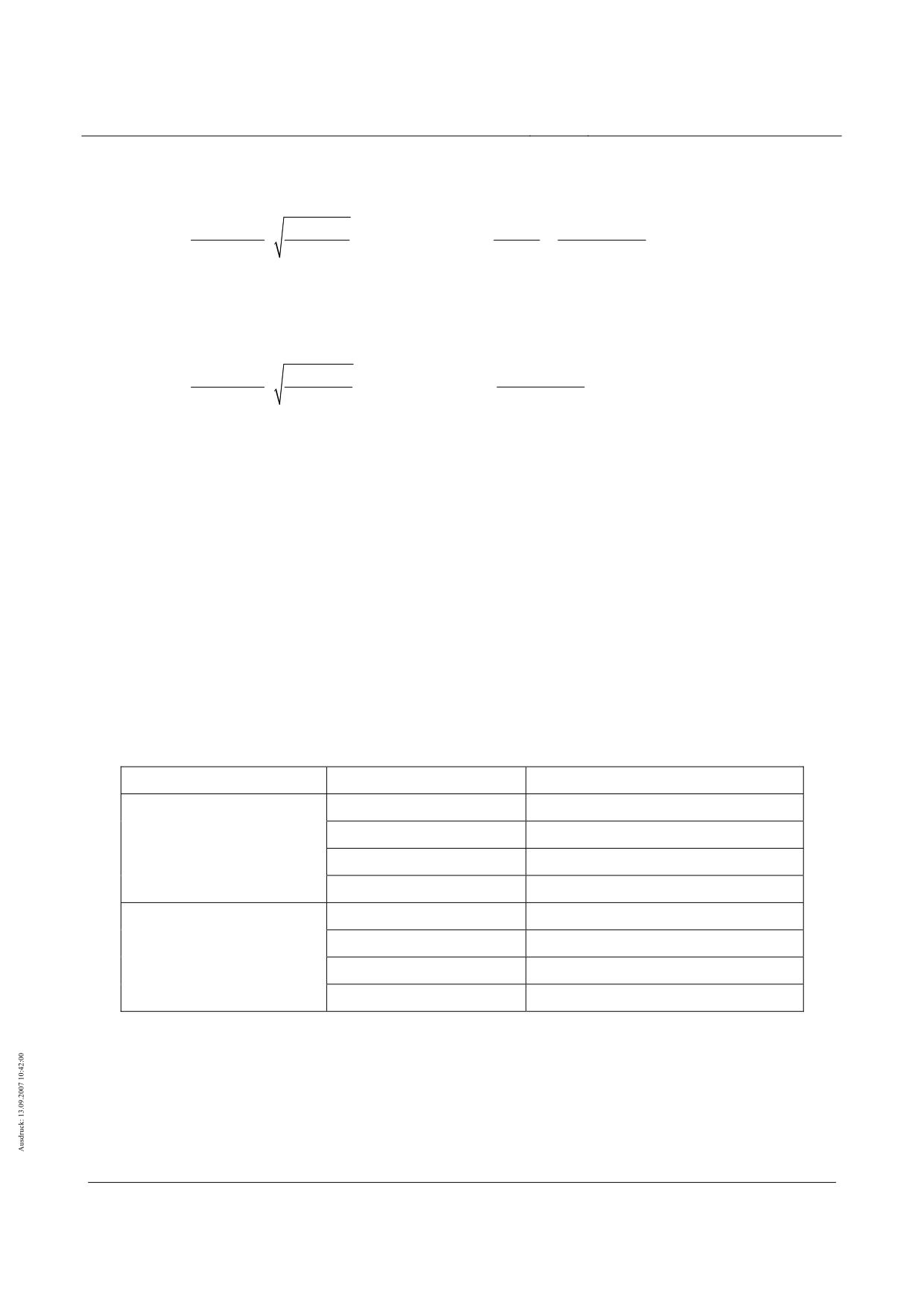
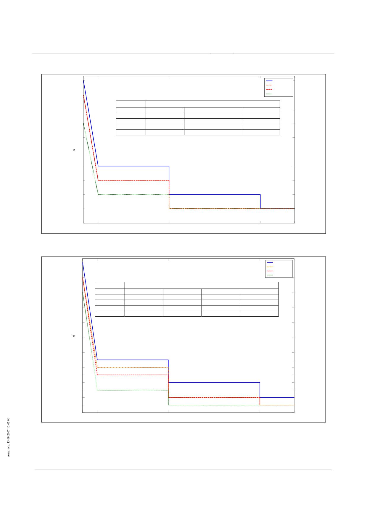
Vibration coefficients for 4-section vehicles
D = 0 %, 0,3 %, 0,6 %, 1,6 %
1.5
1.5
ϕBg,z
1.45
k
D = 0%, 0.3%, 0.6% 1.6%
1.45
1.05 ≤ k ≤ 1.4
1.15 + 1.0 (1.4-k)
1.4 < k ≤ 2.5
1.15
1.4
1.4
2.5 < k ≤ 8.5
1.10
8.5 < k < ∞
1.05
1.35
1.35
1.3
1.3
1.25
1.25
1.2
1.2
1.15
1.15
D = 0%; 0.3%; 0.6%; 1.6%
1.1
1.1
1.05
1.05
1
1
1.05
1.4
2.5
4.5
8.5
10
k [-]
Fig. 174 - ϕBg,z for simple beams where LSt = 24.768 m - 4-section vehicle
1.9
D = 0%; 0.3%
D = 0 %, 0,1.9
D = 0,6 %
D = 1,6 %
D = 0.6%
1.8
ϕBg,z,WSE
1.8
k
D = 0%; 0.3%
D = 0.6%
D = 1.6%
D = 1.6%
1.05 ≤ k ≤ 1.3
1.9
1.8
1.7
1.7
1.3 ≤ k ≤ 1.4
1.3 + 6.0 (1.4-k)
1.3 + 5.0 (1.4-k)
1.3 + 4.0 (1.4-k)
1.7
1.4 < k ≤ 2.5
1.3
1.3
1.3
2.5 < k ≤ 8.5
1.2
1.2
1.1
1.6
8.5 < k < ∞
1.1
1.1
1.05
1.6
1.5
1.5
1.4
1.4
D = 0%; 0.3%; 0.6%; 1.6%
1.3
1.3
D = 0%; 0.3%; 0.6%
1.2
1.2
D = 1.6%
1.1
1.1
D =
1.6%
1.05
1.05
1
1
1.05
1.4
2.5
4.5
8.5
10
1,3
k [-]
Fig. 175 - ϕBg,z, WSE for simple beams where LSt = 24.768 m - 4-section vehicle
Title
High-speed Maglev Systems - Design principles
Guideway - Part II: Design
Doc. no.:
57288
Version
White Paper Issue date
15.02.2007
Page 139
High-speed maglev systems
Maglev Technical Committee
Design principles
Guideway
Vibration coefficients for 6-section vehicles
D = 0 %
1.5
D = 0,3 %, 01.5
D = 1,6 %
1.45
ϕBg,z
1.45
k
D = 0%
D = 0.3%; 0.6%
D = 1.6%
1.05 ≤ k ≤ 1.4
1.2 + 0.857 (1.4-k)
1.15 + 1.0 (1.4-k)
1.1 + 1.143 (1.4-k)
1.4
1.4
1.4 < k ≤ 8.5
1.2
1.15
1.1
8.5 < k < ∞
1.1
1.05
1.05
1.35
1.35
1.3
1.3
1.25
1.25
D = 0%
1.2
1.2
D = 0.3%; 0.6%
1.15
1.15
D = 1.6%
D =
0%
1.1
1.1
D =
0.3% - 1.6%
1.05
1.05
1
1
1.05
1.4
2.5
4.5
8.5
10
k [-]
Fig. 176 - ϕBg,z for simple beams where LSt = 24.768 m - 6-section vehicle
2.1
D = 0 %
2.1
D = 0,3 %
D = 0,6 %
2
D = 1,6 %
2
ϕBg,z,WSE
1.9
k
D = 0%
D = 0.3%
D = 0.6%
D = 1.6%
1.9
1.05 ≤ k ≤ 1.3
2.1
2.0
1.9
1.8
1.8
1.3 ≤ k ≤ 1.4
1.4 + 7.0 (1.4-k)
1.35 + 6.5 (1.4-k)
1.3 + 6.0 (1.4-k)
1.25 + 5.5 (1.4-k)
1.8
1.4 < k ≤ 2.5
1.4
1.35
1.3
1.25
2.5 < k ≤ 8.5
1.4
1.25
1.2
1.1
1.7
1.7
8.5 < k < ∞
1.2
1.1
1.1
1.05
1.6
1.6
1.5
1.5
D = 0%
1.4
1.4
1.35
1.35
1.3
1.3
D = 0.3%
1.25
1.25
D = 0.6%
D = 0%
1.2
1.2
D = 1.6%
D =
0.3% - 0.6%
1.1
1.1
D = 1.6%
1.05
1.05
1
1
1.05
1.4
2.5
4.5
8.5
10
1.3
k [-]
Fig. 177 - ϕBg,z, WSE for simple beams where LSt = 24.768 m - 6-section vehicle
Title
High-speed Maglev Systems - Design principles
Guideway - Part II: Design
Doc. no.:
57288
Version
White Paper Issue date
15.02.2007
Page 140
High-speed maglev systems
Maglev Technical Committee
Design principles
Guideway
Vibration coefficients for 10-section vehicles
D = 0 %
1.5
D = 0,3 %, 0,1.5
D = 1,6 %
1.45
ϕBg,z
1.45
k
D = 0%
D = 0.3%; 0.6%
D = 1.6%
1.05 ≤ k ≤ 1.4
1.3 + 0.571 (1.4-k)
1.2 + 0.857 (1.4-k)
1.15 + 0.714 (1.4-k)
1.4
1.4
1.4 < k ≤ 2.5
1.3
1.2
1.15
2.5 < k ≤ 8.5
1.3
1.2
1.05
1.35
8.5 < k < ∞
1.1
1.05
1.05
1.35
D = 0%
1.3
1.3
1.25
1.25
D = 0.3%; 0.6%
1.2
1.2
1.15
1.15
D =
0%
1.1
1.1
D = 1.6%
D = 0.3% - 1.6%
1.05
1.05
1
1
1.05
1.4
2.5
4.5
8.5
10
k [-]
Fig. 178 - ϕBg,z for simple beams where LSt = 24.768 m - 10-section vehicle
D = 0 2
2.3
.3
D = 0,3 %
D = 0,6 %
2.2
2.2
D = 1,6 %
2.1
2.1
ϕBg,z,WSE
k
D = 0%
D = 0.3%
D = 0.6%
D = 1.6%
2
1.05 ≤ k ≤ 1.4
1.5 + 2.286 (1.4-k)
1.4 + 2.0 (1.4-k)
1.4 + 1.714 (1.4-k)
1.3 + 1.429 (1.4-k)
2
1.4 < k ≤ 2.5
1.5
1.4
1.4
1.3
1.9
2.5 < k ≤ 8.5
1.5
1.4
1.2
1.1
1.9
8.5 < k < ∞
1.2
1.1
1.1
1.05
1.8
1.8
1.7
1.7
1.6
1.6
1.5
D = 0%
1.5
D
= 0.3%; 0.6%
D = 0.3%
1.4
1.4
D
= 1.6%
1.3
1.3
D = 0.6%
D =
0%
1.2
1.2
D = 1.6%
D = 0.3% - 0.6%
1.1
1.1
1.05
D = 1.6%
1.05
1
1
1.05
1.4
2.5
4.5
8.5
10
k [-]
Fig. 179 - ϕBg,z, WSE for simple beams where LSt = 24.768 m - 10-section vehicle
Title
High-speed Maglev Systems - Design principles
Guideway - Part II: Design
Doc. no.:
57288
Version
White Paper Issue date
15.02.2007
Page 141

High-speed maglev systems
Maglev Technical Committee
Design principles
Guideway
Annex II-C: Limit values for routing elements
According to Chapter 4.1.7 of the Guideway design principles for high-speed maglev systems - Part IV:
Routing, the combination of the routing elements - horizontal radius RH, vertical radius RV and the lateral
incline of the guideway α - is limited by the Rx,z criterion. In this regard, the limit value Rx,z is also dependent
on the guideway distortion ∆α. Table 117 gives examples of combination possibilities for routing parameter
limit values.
The longitudinal incline (slope, gradient) is set at s = 0% in Table 117.
Rx,z,min = 530 m where the distortion ∆α = 0°/m
Lateral incline α
Horizontal radius RH
Vertical radius RV,(K/W)
0°
350 m
RV,W ≤ - 530 m
RV,K ≥ 530 m
12°
350 m
RV,W ≤ - 756 m
RV,K ≥ 530 m
5050 m
RV,W ≤ - 530 m
RV,K ≥ 554 m
Rx,z,min = 1100 m where the distortion ∆α = 0.1°/m
0°
350 m
RV,W ≤ - 1100 m
RV,K ≥ 1100 m
12°
350 m
RV,W ≤ - 3105 m
RV,K ≥ 651 m
Table 117 - Limit values for combinations of routing elements
Annex II-D: General limit values relating to de-
formation
The tables of general limit values relating to deformation are in the process of being drawn up. The deforma-
tion limit values to be specified shall be coordinated with the competent supervisory authority, where neces-
sary, until the report is complete.
Annex II-E: Tables of the magnetic forces as a
result of cross-winds (Q9a)
The following tables indicate the appurtenant guidance and levitation magnet forces of the advancing end
and middle sections for vehicle speeds of 0 km/h, 200 km/h, 300 km/h, 400 km/h and 500 km/h and cross-
Title
High-speed Maglev Systems - Design principles
Guideway - Part II: Design
Doc. no.:
57288
Version
White Paper Issue date
15.02.2007
Page 142
High-speed maglev systems
Maglev Technical Committee
Design principles
Guideway
wind speeds of 10 m/s up to 40 m/s. The forces for speeds of travel in between these values, for instance,
shall be determined in relation to a specific project by interpolation/extrapolation.
Title
High-speed Maglev Systems - Design principles
Guideway - Part II: Design
Doc. no.:
57288
Version
White Paper Issue date
15.02.2007
Page 143
High-speed maglev systems
Maglev Technical Committee
Design principles
Guideway
v
W
Guidance magnet forces py,W,FMTi in [kN/m]
[m/s]
1
2
3
4
5
6
7
BM
BM
10
11
12
13
14
15
16
40
-
37.1
13.6
19.5
14.1
13.6
13.8
-
-
11.0
8.1
7.5
6.1
4.9
1.8
1.3
39
-
35.5
13.1
18.9
13.6
13.0
13.3
-
-
10.5
7.8
7.2
5.9
4.7
1.8
1.2
38
-
33.9
12.7
18.2
13.0
12.5
12.7
-
-
10.1
7.5
6.9
5.7
4.5
1.7
1.2
37
-
32.4
12.2
17.6
12.5
12.0
12.2
-
-
9.7
7.2
6.7
5.4
4.3
1.6
1.1
36
-
30.9
11.7
16.9
12.0
11.5
11.6
-
-
9.2
6.9
6.4
5.2
4.2
1.6
1.1
35
-
29.4
11.3
16.3
11.4
11.0
11.1
-
-
8.8
6.6
6.1
5.0
4.0
1.5
1.0
34
-
27.9
10.8
15.6
10.9
10.5
10.6
-
-
8.4
6.3
5.8
4.7
3.8
1.5
1.0
33
-
26.5
10.4
15.0
10.4
10.0
10.1
-
-
8.0
6.0
5.6
4.5
3.6
1.4
0.9
32
-
25.1
9.9
14.4
9.9
9.5
9.6
-
-
7.6
5.7
5.3
4.3
3.4
1.3
0.9
31
-
23.8
9.5
13.8
9.4
9.0
9.1
-
-
7.2
5.4
5.1
4.1
3.3
1.3
0.9
30
-
22.5
9.1
13.2
9.0
8.6
8.6
-
-
6.8
5.1
4.8
3.9
3.1
1.2
0.8
29
-
21.2
8.6
12.6
8.5
8.1
8.2
-
-
6.4
4.9
4.6
3.7
2.9
1.2
0.8
28
-
19.9
8.2
12.0
8.0
7.7
7.7
-
-
6.1
4.6
4.3
3.5
2.8
1.1
0.7
27
-
18.7
7.8
11.4
7.6
7.3
7.3
-
-
5.7
4.3
4.1
3.3
2.6
1.0
0.7
26
-
17.5
7.4
10.8
7.1
6.8
6.8
-
-
5.4
4.1
3.9
3.1
2.5
1.0
0.7
25
-
16.3
7.0
10.3
6.7
6.4
6.4
-
-
5.0
3.8
3.6
2.9
2.3
0.9
0.6
v
W
Levitation magnet forces pz,W,TMTi in [kN/m] (+/-)
[m/s]
(1)
2
3
4
5
6
7
8
9
10
11
12
13
14
15
16
40
7.4
5.6
6.8
4.7
8.3
2.0
5.6
3.2
3.8
4.2
4.8
2.6
5.0
1.4
3.7
39
7.1
5.4
6.5
4.5
8.0
1.9
5.4
3.1
3.6
4.0
4.6
2.5
4.8
1.4
3.6
38
6.8
5.2
6.3
4.4
7.7
1.8
5.2
3.0
3.5
3.9
4.4
2.4
4.6
1.3
3.4
37
6.5
5.0
6.0
4.2
7.4
1.8
5.0
2.8
3.3
3.7
4.2
2.3
4.4
1.3
3.3
36
6.3
4.8
5.7
4.0
7.1
1.7
4.7
2.7
3.2
3.5
4.0
2.2
4.2
1.2
3.1
35
6.0
4.6
5.5
3.8
6.7
1.6
4.5
2.6
3.1
3.4
3.9
2.1
4.1
1.2
3.0
34
5.7
4.4
5.2
3.7
6.4
1.5
4.3
2.5
2.9
3.2
3.7
2.0
3.9
1.1
2.9
33
5.4
4.2
5.0
3.5
6.1
1.5
4.1
2.3
2.8
3.1
3.5
1.9
3.7
1.1
2.7
32
5.2
4.0
4.7
3.3
5.8
1.4
3.9
2.2
2.6
2.9
3.3
1.8
3.5
1.0
2.6
31
4.9
3.8
4.5
3.2
5.6
1.3
3.7
2.1
2.5
2.8
3.2
1.7
3.3
1.0
2.5
30
4.7
3.6
4.2
3.0
5.3
1.2
3.6
2.0
2.4
2.7
3.0
1.6
3.2
0.9
2.3
29
4.4
3.5
4.0
2.9
5.0
1.2
3.4
1.9
2.2
2.5
2.8
1.5
3.0
0.9
2.2
28
4.2
3.3
3.8
2.7
4.7
1.1
3.2
1.8
2.1
2.4
2.7
1.4
2.8
0.8
2.1
27
3.9
3.1
3.6
2.5
4.5
1.0
3.0
1.7
2.0
2.2
2.5
1.4
2.7
0.8
2.0
26
3.7
2.9
3.4
2.4
4.2
1.0
2.8
1.6
1.9
2.1
2.4
1.3
2.5
0.7
1.9
25
3.5
2.8
3.1
2.3
3.9
0.9
2.7
1.5
1.8
2.0
2.2
1.2
2.4
0.7
1.7
Table 118 - Magnetic forces as a result of cross-winds: end section, vFzg = 500 km/h, vW = 25 .. 40 m/s
Title
High-speed Maglev Systems - Design principles
Guideway - Part II: Design
Doc. no.:
57288
Version
White Paper Issue date
15.02.2007
Page 144

High-speed maglev systems
Maglev Technical Committee
Design principles
Guideway
v
W
Guidance magnet forces py,W,FMTi in [kN/m]
[m/s]
1
2
3
4
5
6
7
BM
BM
10
11
12
13
14
15
16
25
-
16.3
7.0
10.3
6.7
6.4
6.4
-
-
5.0
3.8
3.6
2.9
2.3
0.9
0.6
24
-
15.2
6.6
9.7
6.3
6.0
6.0
-
-
4.7
3.6
3.4
2.7
2.2
0.9
0.6
23
-
14.1
6.2
9.2
5.9
5.6
5.6
-
-
4.4
3.4
3.2
2.5
2.0
0.8
0.5
22
-
13.1
5.8
8.6
5.5
5.2
5.2
-
-
4.1
3.1
3.0
2.3
1.9
0.8
0.5
21
-
12.0
5.5
8.1
5.1
4.9
4.8
-
-
3.8
2.9
2.8
2.2
1.8
0.7
0.5
20
-
11.1
5.1
7.6
4.7
4.5
4.4
-
-
3.5
2.7
2.6
2.0
1.6
0.7
0.4
19
-
10.1
4.7
7.0
4.4
4.1
4.1
-
-
3.2
2.5
2.4
1.9
1.5
0.6
0.4
18
-
9.2
4.4
6.5
4.0
3.8
3.7
-
-
2.9
2.3
2.2
1.7
1.4
0.6
0.4
17
-
8.3
4.0
6.1
3.7
3.5
3.4
-
-
2.6
2.1
2.0
1.5
1.2
0.5
0.3
16
-
7.5
3.7
5.6
3.3
3.2
3.1
-
-
2.4
1.9
1.8
1.4
1.1
0.5
0.3
15
-
6.7
3.4
5.1
3.0
2.8
2.8
-
-
2.1
1.7
1.7
1.3
1.0
0.4
0.3
14
-
5.9
3.1
4.6
2.7
2.5
2.5
-
-
1.9
1.5
1.5
1.1
0.9
0.4
0.3
13
-
5.2
2.8
4.2
2.4
2.3
2.2
-
-
1.7
1.4
1.3
1.0
0.8
0.4
0.2
12
-
4.5
2.5
3.8
2.1
2.0
1.9
-
-
1.5
1.2
1.2
0.9
0.7
0.3
0.2
11
-
3.9
2.2
3.3
1.8
1.7
1.7
-
-
1.3
1.0
1.0
0.8
0.6
0.3
0.2
10
-
3.3
1.9
2.9
1.6
1.5
1.4
-
-
1.1
0.9
0.9
0.7
0.5
0.2
0.2
v
W
Levitation magnet forces pz,W,TMTi in [kN/m] (+/-)
[m/s]
(1)
2
3
4
5
6
7
8
9
10
11
12
13
14
15
16
25
3.5
2.8
3.1
2.3
3.9
0.9
2.7
1.5
1.8
2.0
2.2
1.2
2.4
0.7
1.7
24
3.3
2.6
2.9
2.1
3.7
0.9
2.5
1.4
1.6
1.9
2.1
1.1
2.2
0.6
1.6
23
3.0
2.4
2.7
2.0
3.5
0.8
2.3
1.3
1.5
1.7
2.0
1.1
2.1
0.6
1.5
22
2.8
2.3
2.5
1.8
3.2
0.7
2.2
1.2
1.4
1.6
1.8
1.0
1.9
0.6
1.4
21
2.6
2.1
2.4
1.7
3.0
0.7
2.0
1.1
1.3
1.5
1.7
0.9
1.8
0.5
1.3
20
2.4
2.0
2.2
1.6
2.8
0.6
1.9
1.0
1.2
1.4
1.6
0.8
1.6
0.5
1.2
19
2.2
1.8
2.0
1.5
2.5
0.6
1.7
0.9
1.1
1.3
1.4
0.8
1.5
0.4
1.1
18
2.0
1.7
1.8
1.3
2.3
0.5
1.6
0.9
1.0
1.2
1.3
0.7
1.4
0.4
1.0
17
1.9
1.5
1.7
1.2
2.1
0.5
1.4
0.8
0.9
1.1
1.2
0.6
1.3
0.4
0.9
16
1.7
1.4
1.5
1.1
1.9
0.4
1.3
0.7
0.8
1.0
1.1
0.6
1.1
0.3
0.9
15
1.5
1.3
1.4
1.0
1.7
0.4
1.2
0.6
0.8
0.9
1.0
0.5
1.0
0.3
0.8
14
1.4
1.2
1.2
0.9
1.6
0.4
1.1
0.6
0.7
0.8
0.9
0.5
0.9
0.3
0.7
13
1.2
1.0
1.1
0.8
1.4
0.3
0.9
0.5
0.6
0.7
0.8
0.4
0.8
0.2
0.6
12
1.1
0.9
0.9
0.7
1.2
0.3
0.8
0.4
0.5
0.6
0.7
0.4
0.7
0.2
0.5
11
0.9
0.8
0.8
0.6
1.1
0.2
0.7
0.4
0.5
0.5
0.6
0.3
0.6
0.2
0.5
10
0.8
0.7
0.7
0.5
0.9
0.2
0.6
0.3
0.4
0.5
0.5
0.3
0.5
0.2
0.4
Table 119 - Magnetic forces as a result of cross-winds: end section, vFzg = 500 km/h, vW = 10 .. 25 m/s
Title
High-speed Maglev Systems - Design principles
Guideway - Part II: Design
Doc. no.:
57288
Version
White Paper Issue date
15.02.2007
Page 145

High-speed maglev systems
Maglev Technical Committee
Design principles
Guideway
v
W
Guidance magnet forces py,W,FMTi in [kN/m]
[m/s]
1
2
3
4
5
6
7
BM
BM
10
11
12
13
14
15
16
40
2.4
1.8
4.4
6.0
6.2
6.4
8.1
-
-
9.6
9.5
9.8
12.6
10.7
6.1
2.6
39
2.3
1.7
4.3
5.7
5.9
6.2
7.8
-
-
9.1
9.1
9.4
12.1
10.3
5.9
2.5
38
2.2
1.7
4.1
5.5
5.7
5.9
7.5
-
-
8.7
8.7
9.0
11.6
9.9
5.6
2.4
37
2.1
1.6
4.0
5.3
5.5
5.7
7.2
-
-
8.3
8.3
8.7
11.1
9.5
5.4
2.3
36
2.0
1.6
3.8
5.1
5.2
5.5
6.9
-
-
7.9
7.9
8.3
10.7
9.1
5.2
2.2
35
1.9
1.5
3.6
4.8
5.0
5.2
6.6
-
-
7.5
7.5
7.9
10.2
8.7
5.0
2.2
34
1.8
1.5
3.5
4.6
4.8
5.0
6.3
-
-
7.1
7.2
7.6
9.7
8.3
4.8
2.1
33
1.7
1.4
3.3
4.4
4.6
4.8
6.0
-
-
6.7
6.8
7.2
9.3
8.0
4.6
2.0
32
1.6
1.3
3.2
4.2
4.4
4.5
5.7
-
-
6.3
6.5
6.9
8.9
7.6
4.3
1.9
31
1.5
1.3
3.0
4.0
4.2
4.3
5.4
-
-
6.0
6.1
6.5
8.4
7.2
4.1
1.8
30
1.5
1.2
2.9
3.8
4.0
4.1
5.2
-
-
5.6
5.8
6.2
8.0
6.9
3.9
1.8
29
1.4
1.2
2.7
3.6
3.8
3.9
4.9
-
-
5.3
5.5
5.9
7.6
6.5
3.7
1.7
28
1.3
1.1
2.6
3.4
3.6
3.7
4.6
-
-
4.9
5.2
5.6
7.2
6.2
3.5
1.6
27
1.2
1.1
2.5
3.2
3.4
3.5
4.4
-
-
4.6
4.8
5.2
6.8
5.8
3.4
1.5
26
1.1
1.0
2.3
3.0
3.2
3.3
4.1
-
-
4.3
4.5
4.9
6.4
5.5
3.2
1.5
25
1.1
1.0
2.2
2.8
3.0
3.1
3.9
-
-
4.0
4.3
4.6
6.0
5.2
3.0
1.4
v
W
Levitation magnet forces pz,W,TMTi in [kN/m] (+/-)
[m/s]
1
2
3
4
5
6
7
8
9
10
11
12
13
14
15
16
40
1.5
1.6
2.7
1.8
2.5
2.6
1.9
2.1
2.7
1.3
3.9
2.6
3.0
3.9
1.8
1.5
39
1.4
1.6
2.6
1.8
2.4
2.5
1.8
2.0
2.6
1.3
3.8
2.5
2.8
3.8
1.8
1.4
38
1.3
1.5
2.5
1.7
2.3
2.4
1.8
1.8
2.5
1.2
3.6
2.4
2.7
3.6
1.7
1.3
37
1.3
1.4
2.3
1.6
2.2
2.3
1.7
1.7
2.4
1.1
3.5
2.3
2.6
3.5
1.6
1.3
36
1.2
1.4
2.2
1.5
2.1
2.2
1.6
1.6
2.3
1.1
3.3
2.2
2.5
3.3
1.5
1.2
35
1.2
1.3
2.1
1.5
2.0
2.1
1.5
1.5
2.2
1.0
3.2
2.1
2.4
3.2
1.5
1.2
34
1.1
1.3
2.1
1.4
1.9
2.0
1.5
1.4
2.1
1.0
3.0
2.0
2.3
3.0
1.4
1.1
33
1.1
1.2
2.0
1.3
1.8
1.9
1.4
1.3
2.0
1.0
2.9
1.9
2.2
2.9
1.3
1.1
32
1.0
1.1
1.9
1.3
1.7
1.8
1.3
1.2
2.0
0.9
2.8
1.8
2.1
2.7
1.3
1.0
31
1.0
1.1
1.8
1.2
1.7
1.7
1.3
1.1
1.9
0.9
2.6
1.7
2.0
2.6
1.2
1.0
30
0.9
1.0
1.7
1.2
1.6
1.6
1.2
1.1
1.8
0.8
2.5
1.6
1.9
2.5
1.2
0.9
29
0.9
1.0
1.6
1.1
1.5
1.5
1.1
1.0
1.7
0.8
2.4
1.5
1.8
2.3
1.1
0.9
28
0.8
0.9
1.5
1.0
1.4
1.5
1.1
0.9
1.6
0.7
2.3
1.4
1.7
2.2
1.0
0.8
27
0.8
0.9
1.4
1.0
1.3
1.4
1.0
0.8
1.5
0.7
2.1
1.4
1.6
2.1
1.0
0.8
26
0.7
0.8
1.3
0.9
1.2
1.3
0.9
0.8
1.4
0.6
2.0
1.3
1.5
2.0
0.9
0.7
25
0.7
0.8
1.3
0.9
1.2
1.2
0.9
0.7
1.4
0.6
1.9
1.2
1.4
1.8
0.9
0.7
Table 120 - Magnetic forces as a result of cross-winds: middle section, vFzg = 500 km/h, vW = 25 .. 40 m/s
Title
High-speed Maglev Systems - Design principles
Guideway - Part II: Design
Doc. no.:
57288
Version
White Paper Issue date
15.02.2007
Page 146

High-speed maglev systems
Maglev Technical Committee
Design principles
Guideway
v
W
Guidance magnet forces py,W,FMTi in [kN/m]
[m/s]
1
2
3
4
5
6
7
BM
BM
10
11
12
13
14
15
16
25
1.1
1.0
2.2
2.8
3.0
3.1
3.9
-
-
4.0
4.3
4.6
6.0
5.2
3.0
1.4
24
1.0
0.9
2.1
2.7
2.8
2.9
3.6
-
-
3.7
4.0
4.3
5.7
4.9
2.8
1.3
23
0.9
0.9
1.9
2.5
2.6
2.7
3.4
-
-
3.4
3.7
4.1
5.3
4.5
2.6
1.2
22
0.9
0.8
1.8
2.3
2.5
2.5
3.1
-
-
3.2
3.4
3.8
4.9
4.2
2.5
1.2
21
0.8
0.8
1.7
2.2
2.3
2.4
2.9
-
-
2.9
3.2
3.5
4.6
3.9
2.3
1.1
20
0.7
0.7
1.6
2.0
2.1
2.2
2.7
-
-
2.7
2.9
3.3
4.3
3.7
2.1
1.0
19
0.7
0.7
1.5
1.8
2.0
2.0
2.5
-
-
2.4
2.7
3.0
3.9
3.4
2.0
1.0
18
0.6
0.6
1.3
1.7
1.8
1.9
2.3
-
-
2.2
2.4
2.8
3.6
3.1
1.8
0.9
17
0.6
0.6
1.2
1.5
1.7
1.7
2.1
-
-
2.0
2.2
2.5
3.3
2.8
1.7
0.8
16
0.5
0.6
1.1
1.4
1.5
1.5
1.9
-
-
1.8
2.0
2.3
3.0
2.6
1.5
0.8
15
0.4
0.5
1.0
1.3
1.4
1.4
1.7
-
-
1.6
1.8
2.1
2.7
2.3
1.4
0.7
14
0.4
0.5
0.9
1.1
1.2
1.3
1.5
-
-
1.4
1.6
1.8
2.4
2.1
1.2
0.6
13
0.4
0.4
0.8
1.0
1.1
1.1
1.4
-
-
1.2
1.4
1.6
2.2
1.9
1.1
0.6
12
0.3
0.4
0.7
0.9
1.0
1.0
1.2
-
-
1.0
1.2
1.4
1.9
1.7
1.0
0.5
11
0.3
0.3
0.6
0.8
0.8
0.9
1.0
-
-
0.9
1.0
1.3
1.7
1.4
0.9
0.5
10
0.2
0.3
0.6
0.7
0.7
0.7
0.9
-
-
0.7
0.9
1.1
1.4
1.2
0.7
0.4
v
W
Levitation magnet forces pz,W,TMTi in [kN/m] (+/-)
[m/s]
1
2
3
4
5
6
7
8
9
10
11
12
13
14
15
16
25
0.7
0.8
1.3
0.9
1.2
1.2
0.9
0.7
1.4
0.6
1.9
1.2
1.4
1.8
0.9
0.7
24
0.6
0.7
1.2
0.8
1.1
1.1
0.8
0.6
1.3
0.6
1.8
1.1
1.3
1.7
0.8
0.6
23
0.6
0.7
1.1
0.8
1.0
1.1
0.8
0.6
1.2
0.5
1.7
1.0
1.2
1.6
0.8
0.6
22
0.6
0.6
1.0
0.7
1.0
1.0
0.7
0.5
1.1
0.5
1.5
1.0
1.2
1.5
0.7
0.6
21
0.5
0.6
1.0
0.7
0.9
0.9
0.7
0.5
1.1
0.5
1.4
0.9
1.1
1.4
0.7
0.5
20
0.5
0.5
0.9
0.6
0.8
0.9
0.6
0.4
1.0
0.4
1.3
0.8
1.0
1.3
0.6
0.5
19
0.4
0.5
0.8
0.6
0.8
0.8
0.6
0.4
0.9
0.4
1.2
0.8
0.9
1.2
0.6
0.4
18
0.4
0.5
0.7
0.5
0.7
0.7
0.5
0.3
0.8
0.4
1.1
0.7
0.8
1.1
0.5
0.4
17
0.4
0.4
0.7
0.5
0.6
0.7
0.5
0.3
0.8
0.3
1.0
0.6
0.8
1.0
0.5
0.4
16
0.3
0.4
0.6
0.4
0.6
0.6
0.4
0.2
0.7
0.3
0.9
0.6
0.7
0.9
0.4
0.3
15
0.3
0.3
0.6
0.4
0.5
0.5
0.4
0.2
0.6
0.3
0.8
0.5
0.6
0.8
0.4
0.3
14
0.3
0.3
0.5
0.3
0.5
0.5
0.3
0.2
0.6
0.2
0.8
0.5
0.6
0.7
0.3
0.3
13
0.2
0.3
0.4
0.3
0.4
0.4
0.3
0.1
0.5
0.2
0.7
0.4
0.5
0.6
0.3
0.2
12
0.2
0.2
0.4
0.3
0.4
0.4
0.3
0.1
0.5
0.2
0.6
0.4
0.4
0.6
0.3
0.2
11
0.2
0.2
0.3
0.2
0.3
0.3
0.2
0.1
0.4
0.2
0.5
0.3
0.4
0.5
0.2
0.2
10
0.2
0.2
0.3
0.2
0.3
0.3
0.2
0.1
0.4
0.1
0.4
0.3
0.3
0.4
0.2
0.2
Table 121 - Magnetic forces as a result of cross-winds: middle section, vFzg = 500 km/h, vW = 10 .. 25 m/s
Title
High-speed Maglev Systems - Design principles
Guideway - Part II: Design
Doc. no.:
57288
Version
White Paper Issue date
15.02.2007
Page 147
High-speed maglev systems
Maglev Technical Committee
Design principles
Guideway
v
W
Guidance magnet forces py,W,FMTi in [kN/m]
[m/s]
1
2
3
4
5
6
7
BM
BM
10
11
12
13
14
15
16
40
-
27.9
13.4
18.6
13.2
12.7
12.9
-
-
10.2
7.6
7.1
5.6
4.6
1.9
1.0
39
-
26.7
12.9
18.0
12.7
12.2
12.4
-
-
9.8
7.3
6.8
5.4
4.4
1.8
0.9
38
-
25.5
12.4
17.4
12.2
11.7
11.9
-
-
9.4
7.0
6.5
5.2
4.2
1.8
0.9
37
-
24.4
11.9
16.7
11.7
11.2
11.4
-
-
9.0
6.7
6.3
5.0
4.0
1.7
0.9
36
-
23.3
11.4
16.1
11.2
10.7
10.9
-
-
8.6
6.4
6.0
4.7
3.9
1.6
0.8
35
-
22.2
11.0
15.5
10.7
10.3
10.4
-
-
8.2
6.1
5.7
4.5
3.7
1.6
0.8
34
-
21.1
10.5
14.9
10.2
9.8
9.9
-
-
7.8
5.9
5.5
4.3
3.5
1.5
0.8
33
-
20.0
10.0
14.3
9.7
9.3
9.4
-
-
7.4
5.6
5.3
4.1
3.3
1.4
0.7
32
-
19.0
9.6
13.7
9.3
8.9
9.0
-
-
7.0
5.3
5.0
3.9
3.2
1.4
0.7
31
-
18.0
9.2
13.1
8.8
8.5
8.5
-
-
6.7
5.1
4.8
3.7
3.0
1.3
0.7
30
-
17.0
8.7
12.6
8.4
8.0
8.1
-
-
6.3
4.8
4.5
3.5
2.9
1.3
0.6
29
-
16.1
8.3
12.0
7.9
7.6
7.6
-
-
6.0
4.6
4.3
3.3
2.7
1.2
0.6
28
-
15.1
7.9
11.4
7.5
7.2
7.2
-
-
5.6
4.3
4.1
3.2
2.6
1.1
0.6
27
-
14.2
7.5
10.9
7.1
6.8
6.8
-
-
5.3
4.1
3.9
3.0
2.4
1.1
0.5
26
-
13.3
7.0
10.3
6.7
6.4
6.4
-
-
5.0
3.8
3.6
2.8
2.3
1.0
0.5
25
-
12.5
6.6
9.8
6.3
6.0
6.0
-
-
4.7
3.6
3.4
2.6
2.1
1.0
0.5
v
W
Levitation magnet forces pz,W,TMTi in [kN/m] (+/-)
[m/s]
(1)
2
3
4
5
6
7
8
9
10
11
12
13
14
15
16
40
6.6
5.4
6.4
4.4
7.9
1.8
5.3
3.0
3.5
3.9
4.5
2.4
4.7
1.3
3.5
39
6.3
5.2
6.1
4.2
7.6
1.7
5.1
2.9
3.4
3.7
4.3
2.3
4.5
1.2
3.3
38
6.1
5.0
5.8
4.0
7.2
1.7
4.8
2.7
3.2
3.6
4.1
2.2
4.3
1.2
3.2
37
5.8
4.8
5.6
3.9
6.9
1.6
4.6
2.6
3.1
3.4
3.9
2.1
4.1
1.1
3.1
36
5.6
4.6
5.4
3.7
6.7
1.5
4.4
2.5
3.0
3.3
3.8
2.0
4.0
1.1
2.9
35
5.3
4.4
5.1
3.5
6.4
1.5
4.3
2.4
2.8
3.2
3.6
1.9
3.8
1.0
2.8
34
5.1
4.2
4.9
3.4
6.1
1.4
4.1
2.3
2.7
3.0
3.4
1.8
3.6
1.0
2.7
33
4.8
4.0
4.6
3.2
5.8
1.3
3.9
2.2
2.6
2.9
3.3
1.7
3.4
1.0
2.5
32
4.6
3.8
4.4
3.1
5.5
1.3
3.7
2.1
2.4
2.7
3.1
1.7
3.3
0.9
2.4
31
4.4
3.6
4.2
2.9
5.2
1.2
3.5
2.0
2.3
2.6
3.0
1.6
3.1
0.9
2.3
30
4.2
3.5
4.0
2.8
5.0
1.1
3.3
1.9
2.2
2.5
2.8
1.5
2.9
0.8
2.2
29
3.9
3.3
3.7
2.6
4.7
1.1
3.1
1.8
2.1
2.3
2.7
1.4
2.8
0.8
2.1
28
3.7
3.1
3.5
2.5
4.5
1.0
3.0
1.7
2.0
2.2
2.5
1.3
2.6
0.7
2.0
27
3.5
3.0
3.3
2.4
4.2
0.9
2.8
1.6
1.9
2.1
2.4
1.3
2.5
0.7
1.8
26
3.3
2.8
3.1
2.2
4.0
0.9
2.6
1.5
1.7
2.0
2.2
1.2
2.3
0.7
1.7
25
3.1
2.6
2.9
2.1
3.7
0.8
2.5
1.4
1.6
1.9
2.1
1.1
2.2
0.6
1.6
Table 122 - Magnetic forces as a result of cross-winds: end section, vFzg = 400 km/h, vW = 25 .. 40 m/s
Title
High-speed Maglev Systems - Design principles
Guideway - Part II: Design
Doc. no.:
57288
Version
White Paper Issue date
15.02.2007
Page 148
High-speed maglev systems
Maglev Technical Committee
Design principles
Guideway
v
W
Guidance magnet forces py,W,FMTi in [kN/m]
[m/s]
1
2
3
4
5
6
7
BM
BM
10
11
12
13
14
15
16
25
-
12.5
6.6
9.8
6.3
6.0
6.0
-
-
4.7
3.6
3.4
2.6
2.1
1.0
0.5
24
-
11.6
6.3
9.2
5.9
5.6
5.6
-
-
4.3
3.4
3.2
2.5
2.0
0.9
0.4
23
-
10.8
5.9
8.7
5.5
5.3
5.2
-
-
4.0
3.2
3.0
2.3
1.9
0.9
0.4
22
-
10.0
5.5
8.2
5.1
4.9
4.8
-
-
3.8
2.9
2.8
2.1
1.7
0.8
0.4
21
-
9.2
5.1
7.7
4.8
4.6
4.5
-
-
3.5
2.7
2.6
2.0
1.6
0.7
0.4
20
-
8.5
4.8
7.2
4.4
4.2
4.1
-
-
3.2
2.5
2.4
1.8
1.5
0.7
0.3
19
-
7.8
4.4
6.7
4.1
3.9
3.8
-
-
2.9
2.3
2.2
1.7
1.4
0.6
0.3
18
-
7.1
4.1
6.2
3.7
3.6
3.5
-
-
2.7
2.1
2.1
1.6
1.3
0.6
0.3
17
-
6.4
3.7
5.8
3.4
3.3
3.2
-
-
2.4
1.9
1.9
1.4
1.2
0.6
0.3
16
-
5.8
3.4
5.3
3.1
3.0
2.9
-
-
2.2
1.8
1.7
1.3
1.0
0.5
0.2
15
-
5.2
3.1
4.9
2.8
2.7
2.6
-
-
2.0
1.6
1.6
1.2
0.9
0.5
0.2
14
-
4.6
2.8
4.4
2.5
2.4
2.3
-
-
1.8
1.4
1.4
1.0
0.8
0.4
0.2
13
-
4.1
2.5
4.0
2.2
2.1
2.0
-
-
1.6
1.3
1.2
0.9
0.8
0.4
0.2
12
-
3.5
2.2
3.6
2.0
1.9
1.8
-
-
1.4
1.1
1.1
0.8
0.7
0.3
0.2
11
-
3.1
2.0
3.2
1.7
1.6
1.6
-
-
1.2
1.0
1.0
0.7
0.6
0.3
0.1
10
-
2.6
1.7
2.8
1.5
1.4
1.3
-
-
1.0
0.8
0.8
0.6
0.5
0.3
0.1
v
W
Levitation magnet forces pz,W,TMTi in [kN/m] (+/-)
[m/s]
(1)
2
3
4
5
6
7
8
9
10
11
12
13
14
15
16
25
3.1
2.6
2.9
2.1
3.7
0.8
2.5
1.4
1.6
1.9
2.1
1.1
2.2
0.6
1.6
24
2.9
2.5
2.7
2.0
3.5
0.8
2.3
1.3
1.5
1.7
2.0
1.0
2.1
0.6
1.5
23
2.7
2.3
2.6
1.8
3.3
0.7
2.2
1.2
1.4
1.6
1.8
1.0
1.9
0.5
1.4
22
2.5
2.2
2.4
1.7
3.0
0.7
2.0
1.1
1.3
1.5
1.7
0.9
1.8
0.5
1.3
21
2.3
2.0
2.2
1.6
2.8
0.6
1.9
1.0
1.2
1.4
1.6
0.8
1.7
0.5
1.2
20
2.2
1.9
2.0
1.5
2.6
0.6
1.7
1.0
1.1
1.3
1.5
0.8
1.5
0.4
1.1
19
2.0
1.7
1.9
1.4
2.4
0.5
1.6
0.9
1.0
1.2
1.3
0.7
1.4
0.4
1.0
18
1.8
1.6
1.7
1.2
2.2
0.5
1.5
0.8
1.0
1.1
1.2
0.7
1.3
0.4
1.0
17
1.7
1.5
1.6
1.1
2.0
0.4
1.3
0.7
0.9
1.0
1.1
0.6
1.2
0.3
0.9
16
1.5
1.3
1.4
1.0
1.8
0.4
1.2
0.7
0.8
0.9
1.0
0.5
1.1
0.3
0.8
15
1.4
1.2
1.3
0.9
1.6
0.4
1.1
0.6
0.7
0.8
0.9
0.5
1.0
0.3
0.7
14
1.2
1.1
1.1
0.8
1.5
0.3
1.0
0.5
0.6
0.7
0.8
0.4
0.9
0.2
0.6
13
1.1
1.0
1.0
0.7
1.3
0.3
0.9
0.5
0.6
0.7
0.7
0.4
0.8
0.2
0.6
12
0.9
0.9
0.9
0.7
1.2
0.2
0.8
0.4
0.5
0.6
0.6
0.3
0.7
0.2
0.5
11
0.8
0.8
0.8
0.6
1.0
0.2
0.7
0.4
0.4
0.5
0.6
0.3
0.6
0.2
0.4
10
0.7
0.7
0.7
0.5
0.9
0.2
0.6
0.3
0.4
0.4
0.5
0.3
0.5
0.1
0.4
Table 123 - Magnetic forces as a result of cross-winds: end section, vFzg = 400 km/h, vW = 10 .. 25 m/s
Title
High-speed Maglev Systems - Design principles
Guideway - Part II: Design
Doc. no.:
57288
Version
White Paper Issue date
15.02.2007
Page 149

High-speed maglev systems
Maglev Technical Committee
Design principles
Guideway
v
W
Guidance magnet forces py,W,FMTi in [kN/m]
[m/s]
1
2
3
4
5
6
7
BM
BM
10
11
12
13
14
15
16
40
1.4
2.1
4.2
5.0
5.7
5.9
7.4
-
-
8.7
8.8
9.2
10.8
8.6
4.4
2.3
39
1.4
2.0
4.1
4.8
5.4
5.7
7.1
-
-
8.3
8.5
8.8
10.3
8.2
4.3
2.2
38
1.3
2.0
3.9
4.6
5.2
5.4
6.8
-
-
7.9
8.1
8.5
9.9
7.9
4.1
2.1
37
1.3
1.9
3.8
4.4
5.0
5.2
6.5
-
-
7.5
7.7
8.1
9.5
7.6
3.9
2.1
36
1.2
1.8
3.6
4.2
4.8
5.0
6.2
-
-
7.2
7.4
7.8
9.1
7.3
3.8
2.0
35
1.2
1.8
3.5
4.1
4.6
4.8
6.0
-
-
6.8
7.0
7.4
8.7
7.0
3.6
1.9
34
1.1
1.7
3.3
3.9
4.4
4.6
5.7
-
-
6.4
6.7
7.1
8.3
6.7
3.5
1.8
33
1.0
1.7
3.2
3.7
4.2
4.4
5.4
-
-
6.1
6.4
6.8
8.0
6.4
3.3
1.8
32
1.0
1.6
3.0
3.5
4.0
4.2
5.2
-
-
5.8
6.0
6.4
7.6
6.1
3.2
1.7
31
0.9
1.5
2.9
3.3
3.8
4.0
4.9
-
-
5.4
5.7
6.1
7.2
5.8
3.0
1.6
30
0.9
1.5
2.8
3.2
3.6
3.8
4.7
-
-
5.1
5.4
5.8
6.9
5.5
2.9
1.6
29
0.8
1.4
2.6
3.0
3.4
3.6
4.4
-
-
4.8
5.1
5.5
6.5
5.2
2.7
1.5
28
0.8
1.3
2.5
2.9
3.3
3.4
4.2
-
-
4.5
4.8
5.2
6.2
4.9
2.6
1.4
27
0.7
1.3
2.4
2.7
3.1
3.2
3.9
-
-
4.2
4.5
4.9
5.8
4.7
2.4
1.4
26
0.7
1.2
2.2
2.5
2.9
3.0
3.7
-
-
3.9
4.2
4.6
5.5
4.4
2.3
1.3
25
0.7
1.2
2.1
2.4
2.7
2.8
3.5
-
-
3.6
4.0
4.4
5.2
4.1
2.2
1.2
v
W
Levitation magnet forces pz,W,TMTi in [kN/m] (+/-)
[m/s]
1
2
3
4
5
6
7
8
9
10
11
12
13
14
15
16
40
1.3
1.5
2.4
1.7
2.3
2.3
1.8
1.9
2.5
1.2
3.6
2.4
2.7
3.7
1.8
1.3
39
1.3
1.4
2.3
1.6
2.2
2.3
1.7
1.8
2.4
1.2
3.5
2.3
2.6
3.5
1.7
1.3
38
1.2
1.4
2.2
1.6
2.1
2.2
1.6
1.7
2.3
1.1
3.3
2.2
2.5
3.4
1.6
1.2
37
1.2
1.3
2.1
1.5
2.0
2.1
1.6
1.6
2.2
1.1
3.2
2.1
2.4
3.2
1.6
1.2
36
1.1
1.3
2.0
1.4
1.9
2.0
1.5
1.5
2.2
1.0
3.1
2.0
2.3
3.1
1.5
1.1
35
1.1
1.2
2.0
1.4
1.9
1.9
1.4
1.4
2.1
1.0
2.9
1.9
2.2
2.9
1.4
1.1
34
1.0
1.2
1.9
1.3
1.8
1.8
1.4
1.3
2.0
0.9
2.8
1.8
2.1
2.8
1.4
1.0
33
1.0
1.1
1.8
1.2
1.7
1.7
1.3
1.2
1.9
0.9
2.7
1.8
2.0
2.7
1.3
1.0
32
0.9
1.1
1.7
1.2
1.6
1.6
1.2
1.1
1.8
0.8
2.5
1.7
1.9
2.6
1.2
0.9
31
0.9
1.0
1.6
1.1
1.5
1.6
1.2
1.0
1.7
0.8
2.4
1.6
1.8
2.4
1.2
0.9
30
0.8
0.9
1.5
1.1
1.4
1.5
1.1
1.0
1.6
0.8
2.3
1.5
1.7
2.3
1.1
0.8
29
0.8
0.9
1.5
1.0
1.4
1.4
1.0
0.9
1.6
0.7
2.2
1.4
1.6
2.2
1.1
0.8
28
0.7
0.8
1.4
1.0
1.3
1.3
1.0
0.8
1.5
0.7
2.1
1.3
1.6
2.1
1.0
0.7
27
0.7
0.8
1.3
0.9
1.2
1.3
0.9
0.8
1.4
0.6
1.9
1.3
1.5
1.9
0.9
0.7
26
0.7
0.8
1.2
0.9
1.1
1.2
0.9
0.7
1.3
0.6
1.8
1.2
1.4
1.8
0.9
0.7
25
0.6
0.7
1.1
0.8
1.1
1.1
0.8
0.6
1.3
0.6
1.7
1.1
1.3
1.7
0.8
0.6
Table 124 - Magnetic forces as a result of cross-winds: middle section, vFzg = 400 km/h, vW = 25 .. 40 m/s
Title
High-speed Maglev Systems - Design principles
Guideway - Part II: Design
Doc. no.:
57288
Version
White Paper Issue date
15.02.2007
Page 150

High-speed maglev systems
Maglev Technical Committee
Design principles
Guideway
v
W
Guidance magnet forces py,W,FMTi in [kN/m]
[m/s]
1
2
3
4
5
6
7
BM
BM
10
11
12
13
14
15
16
25
0.7
1.2
2.1
2.4
2.7
2.8
3.5
-
-
3.6
4.0
4.4
5.2
4.1
2.2
1.2
24
0.6
1.1
2.0
2.2
2.6
2.6
3.3
-
-
3.4
3.7
4.1
4.8
3.9
2.0
1.2
23
0.6
1.0
1.9
2.1
2.4
2.5
3.1
-
-
3.1
3.4
3.8
4.5
3.6
1.9
1.1
22
0.5
1.0
1.7
1.9
2.3
2.3
2.8
-
-
2.9
3.2
3.6
4.2
3.4
1.8
1.0
21
0.5
0.9
1.6
1.8
2.1
2.2
2.6
-
-
2.6
2.9
3.3
3.9
3.2
1.7
1.0
20
0.4
0.9
1.5
1.7
1.9
2.0
2.4
-
-
2.4
2.7
3.1
3.6
2.9
1.5
0.9
19
0.4
0.8
1.4
1.5
1.8
1.8
2.3
-
-
2.2
2.5
2.8
3.4
2.7
1.4
0.8
18
0.4
0.8
1.3
1.4
1.7
1.7
2.1
-
-
2.0
2.3
2.6
3.1
2.5
1.3
0.8
17
0.3
0.7
1.2
1.3
1.5
1.5
1.9
-
-
1.8
2.1
2.4
2.8
2.3
1.2
0.7
16
0.3
0.7
1.1
1.2
1.4
1.4
1.7
-
-
1.6
1.9
2.1
2.6
2.1
1.1
0.7
15
0.3
0.6
1.0
1.1
1.2
1.3
1.6
-
-
1.4
1.7
1.9
2.3
1.9
1.0
0.6
14
0.2
0.5
0.9
1.0
1.1
1.1
1.4
-
-
1.2
1.5
1.7
2.1
1.7
0.9
0.6
13
0.2
0.5
0.8
0.8
1.0
1.0
1.2
-
-
1.1
1.3
1.5
1.9
1.5
0.8
0.5
12
0.2
0.5
0.7
0.7
0.9
0.9
1.1
-
-
0.9
1.1
1.4
1.6
1.3
0.7
0.5
11
0.2
0.4
0.6
0.7
0.8
0.8
0.9
-
-
0.8
1.0
1.2
1.4
1.2
0.6
0.4
10
0.1
0.4
0.5
0.6
0.7
0.7
0.8
-
-
0.7
0.8
1.0
1.2
1.0
0.5
0.4
v
W
Levitation magnet forces pz,W,TMTi in [kN/m] (+/-)
[m/s]
1
2
3
4
5
6
7
8
9
10
11
12
13
14
15
16
25
0.6
0.7
1.1
0.8
1.1
1.1
0.8
0.6
1.3
0.6
1.7
1.1
1.3
1.7
0.8
0.6
24
0.6
0.7
1.1
0.8
1.0
1.0
0.8
0.6
1.2
0.5
1.6
1.0
1.2
1.6
0.8
0.6
23
0.5
0.6
1.0
0.7
0.9
1.0
0.7
0.5
1.1
0.5
1.5
1.0
1.1
1.5
0.7
0.5
22
0.5
0.6
0.9
0.7
0.9
0.9
0.7
0.5
1.0
0.5
1.4
0.9
1.1
1.4
0.7
0.5
21
0.5
0.5
0.9
0.6
0.8
0.8
0.6
0.4
1.0
0.4
1.3
0.8
1.0
1.3
0.6
0.5
20
0.4
0.5
0.8
0.6
0.8
0.8
0.6
0.4
0.9
0.4
1.2
0.8
0.9
1.2
0.6
0.4
19
0.4
0.5
0.7
0.5
0.7
0.7
0.5
0.3
0.8
0.4
1.1
0.7
0.8
1.1
0.5
0.4
18
0.4
0.4
0.7
0.5
0.6
0.7
0.5
0.3
0.8
0.3
1.0
0.7
0.8
1.0
0.5
0.4
17
0.3
0.4
0.6
0.4
0.6
0.6
0.4
0.3
0.7
0.3
0.9
0.6
0.7
0.9
0.4
0.3
16
0.3
0.3
0.6
0.4
0.5
0.6
0.4
0.2
0.7
0.3
0.9
0.5
0.6
0.8
0.4
0.3
15
0.3
0.3
0.5
0.4
0.5
0.5
0.3
0.2
0.6
0.2
0.8
0.5
0.6
0.8
0.4
0.3
14
0.2
0.3
0.5
0.3
0.4
0.4
0.3
0.2
0.5
0.2
0.7
0.4
0.5
0.7
0.3
0.2
13
0.2
0.2
0.4
0.3
0.4
0.4
0.3
0.1
0.5
0.2
0.6
0.4
0.5
0.6
0.3
0.2
12
0.2
0.2
0.4
0.3
0.3
0.3
0.2
0.1
0.4
0.2
0.5
0.3
0.4
0.5
0.3
0.2
11
0.2
0.2
0.3
0.2
0.3
0.3
0.2
0.1
0.4
0.1
0.5
0.3
0.4
0.5
0.2
0.2
10
0.1
0.2
0.3
0.2
0.2
0.3
0.2
0.1
0.3
0.1
0.4
0.3
0.3
0.4
0.2
0.1
Table 125 - Magnetic forces as a result of cross-winds: middle section, vFzg = 400 km/h, vW = 10 .. 25 m/s
Title
High-speed Maglev Systems - Design principles
Guideway - Part II: Design
Doc. no.:
57288
Version
White Paper Issue date
15.02.2007
Page 151
High-speed maglev systems
Maglev Technical Committee
Design principles
Guideway
v
W
Guidance magnet forces py,W,FMTi in [kN/m]
[m/s]
1
2
3
4
5
6
7
BM
BM
10
11
12
13
14
15
16
40
-
15.1
9.6
15.7
12.1
11.7
11.7
-
-
9.2
6.9
6.5
5.0
4.1
1.8
0.6
39
-
14.5
9.2
15.2
11.6
11.2
11.2
-
-
8.8
6.6
6.2
4.8
3.9
1.8
0.6
38
-
13.8
8.9
14.7
11.2
10.7
10.7
-
-
8.4
6.4
6.0
4.6
3.8
1.7
0.6
37
-
13.2
8.5
14.1
10.7
10.3
10.3
-
-
8.0
6.1
5.7
4.4
3.6
1.6
0.6
36
-
12.6
8.2
13.6
10.2
9.9
9.8
-
-
7.7
5.8
5.5
4.2
3.5
1.6
0.5
35
-
12.0
7.8
13.1
9.8
9.4
9.4
-
-
7.3
5.6
5.3
4.0
3.3
1.5
0.5
34
-
11.4
7.5
12.6
9.4
9.0
8.9
-
-
7.0
5.3
5.0
3.8
3.2
1.5
0.5
33
-
10.9
7.2
12.1
8.9
8.6
8.5
-
-
6.6
5.1
4.8
3.7
3.0
1.4
0.5
32
-
10.3
6.8
11.6
8.5
8.2
8.1
-
-
6.3
4.8
4.6
3.5
2.9
1.3
0.5
31
-
9.8
6.5
11.1
8.1
7.8
7.7
-
-
6.0
4.6
4.4
3.3
2.7
1.3
0.4
30
-
9.2
6.2
10.6
7.7
7.4
7.3
-
-
5.7
4.4
4.1
3.1
2.6
1.2
0.4
29
-
8.7
5.9
10.1
7.3
7.0
6.9
-
-
5.4
4.1
3.9
3.0
2.4
1.2
0.4
28
-
8.2
5.6
9.7
6.9
6.6
6.5
-
-
5.1
3.9
3.7
2.8
2.3
1.1
0.4
27
-
7.7
5.3
9.2
6.5
6.2
6.1
-
-
4.8
3.7
3.5
2.7
2.2
1.0
0.3
26
-
7.2
5.0
8.7
6.1
5.9
5.8
-
-
4.5
3.5
3.3
2.5
2.1
1.0
0.3
25
-
6.7
4.7
8.3
5.8
5.5
5.4
-
-
4.2
3.3
3.1
2.3
1.9
0.9
0.3
v
W
Levitation magnet forces pz,W,TMTi in [kN/m] (+/-)
[m/s]
(1)
2
3
4
5
6
7
8
9
10
11
12
13
14
15
16
40
5.7
4.9
5.8
3.9
7.2
1.6
4.8
2.7
3.2
3.5
4.0
2.1
4.2
1.2
3.1
39
5.5
4.8
5.5
3.8
6.9
1.5
4.6
2.6
3.1
3.4
3.9
2.0
4.1
1.1
3.0
38
5.3
4.6
5.3
3.6
6.7
1.5
4.4
2.5
2.9
3.3
3.7
2.0
3.9
1.1
2.9
37
5.0
4.4
5.1
3.5
6.4
1.4
4.2
2.4
2.8
3.1
3.6
1.9
3.7
1.0
2.8
36
4.8
4.2
4.9
3.3
6.1
1.3
4.1
2.3
2.7
3.0
3.4
1.8
3.6
1.0
2.6
35
4.6
4.0
4.6
3.2
5.8
1.3
3.9
2.2
2.6
2.9
3.3
1.7
3.4
0.9
2.5
34
4.4
3.9
4.4
3.0
5.6
1.2
3.7
2.1
2.4
2.7
3.1
1.6
3.3
0.9
2.4
33
4.2
3.7
4.2
2.9
5.3
1.2
3.5
2.0
2.3
2.6
3.0
1.6
3.1
0.9
2.3
32
4.0
3.5
4.0
2.7
5.1
1.1
3.4
1.9
2.2
2.5
2.8
1.5
3.0
0.8
2.2
31
3.8
3.4
3.8
2.6
4.8
1.0
3.2
1.8
2.1
2.4
2.7
1.4
2.8
0.8
2.1
30
3.6
3.2
3.6
2.5
4.6
1.0
3.0
1.7
2.0
2.2
2.5
1.3
2.7
0.7
2.0
29
3.4
3.1
3.4
2.4
4.3
0.9
2.9
1.6
1.9
2.1
2.4
1.3
2.5
0.7
1.9
28
3.2
2.9
3.2
2.2
4.1
0.9
2.7
1.5
1.8
2.0
2.3
1.2
2.4
0.7
1.8
27
3.0
2.7
3.0
2.1
3.9
0.8
2.6
1.4
1.7
1.9
2.1
1.1
2.2
0.6
1.7
26
2.9
2.6
2.8
2.0
3.6
0.8
2.4
1.3
1.6
1.8
2.0
1.1
2.1
0.6
1.6
25
2.7
2.4
2.7
1.9
3.4
0.7
2.3
1.2
1.5
1.7
1.9
1.0
2.0
0.6
1.5
Table 126 - Magnetic forces as a result of cross-winds: end section, vFzg = 300 km/h, vW = 25 .. 40 m/s
Title
High-speed Maglev Systems - Design principles
Guideway - Part II: Design
Doc. no.:
57288
Version
White Paper Issue date
15.02.2007
Page 152
High-speed maglev systems
Maglev Technical Committee
Design principles
Guideway
v
W
Guidance magnet forces py,W,FMTi in [kN/m]
[m/s]
1
2
3
4
5
6
7
BM
BM
10
11
12
13
14
15
16
25
-
6.7
4.7
8.3
5.8
5.5
5.4
-
-
4.2
3.3
3.1
2.3
1.9
0.9
0.3
24
-
6.3
4.5
7.8
5.4
5.2
5.0
-
-
3.9
3.1
2.9
2.2
1.8
0.9
0.3
23
-
5.8
4.2
7.4
5.0
4.8
4.7
-
-
3.6
2.9
2.8
2.1
1.7
0.8
0.3
22
-
5.4
3.9
6.9
4.7
4.5
4.4
-
-
3.4
2.7
2.6
1.9
1.6
0.8
0.3
21
-
5.0
3.6
6.5
4.4
4.2
4.1
-
-
3.1
2.5
2.4
1.8
1.5
0.7
0.2
20
-
4.6
3.4
6.1
4.0
3.9
3.7
-
-
2.9
2.3
2.2
1.6
1.3
0.7
0.2
19
-
4.2
3.1
5.7
3.7
3.6
3.4
-
-
2.6
2.1
2.0
1.5
1.2
0.6
0.2
18
-
3.8
2.9
5.3
3.4
3.3
3.1
-
-
2.4
1.9
1.9
1.4
1.1
0.6
0.2
17
-
3.5
2.7
4.9
3.1
3.0
2.9
-
-
2.2
1.8
1.7
1.3
1.0
0.5
0.2
16
-
3.1
2.4
4.5
2.8
2.7
2.6
-
-
2.0
1.6
1.6
1.1
0.9
0.5
0.2
15
-
2.8
2.2
4.1
2.6
2.4
2.3
-
-
1.8
1.5
1.4
1.0
0.9
0.4
0.1
14
-
2.5
2.0
3.7
2.3
2.2
2.1
-
-
1.6
1.3
1.3
0.9
0.8
0.4
0.1
13
-
2.2
1.8
3.4
2.0
1.9
1.8
-
-
1.4
1.2
1.1
0.8
0.7
0.4
0.1
12
-
1.9
1.6
3.0
1.8
1.7
1.6
-
-
1.2
1.0
1.0
0.7
0.6
0.3
0.1
11
-
1.6
1.4
2.7
1.6
1.5
1.4
-
-
1.1
0.9
0.9
0.6
0.5
0.3
0.1
10
-
1.4
1.2
2.4
1.3
1.3
1.2
-
-
0.9
0.8
0.8
0.5
0.4
0.2
0.1
v
W
Levitation magnet forces pz,W,TMTi in [kN/m] (+/-)
[m/s]
(1)
2
3
4
5
6
7
8
9
10
11
12
13
14
15
16
25
2.7
2.4
2.7
1.9
3.4
0.7
2.3
1.2
1.5
1.7
1.9
1.0
2.0
0.6
1.5
24
2.5
2.3
2.5
1.7
3.2
0.7
2.1
1.2
1.4
1.6
1.8
0.9
1.9
0.5
1.4
23
2.3
2.2
2.3
1.6
3.0
0.6
2.0
1.1
1.3
1.5
1.7
0.9
1.7
0.5
1.3
22
2.2
2.0
2.2
1.5
2.8
0.6
1.8
1.0
1.2
1.4
1.5
0.8
1.6
0.5
1.2
21
2.0
1.9
2.0
1.4
2.6
0.5
1.7
0.9
1.1
1.3
1.4
0.8
1.5
0.4
1.1
20
1.9
1.7
1.8
1.3
2.4
0.5
1.6
0.9
1.0
1.2
1.3
0.7
1.4
0.4
1.0
19
1.7
1.6
1.7
1.2
2.2
0.5
1.5
0.8
0.9
1.1
1.2
0.6
1.3
0.4
0.9
18
1.6
1.5
1.6
1.1
2.0
0.4
1.3
0.7
0.9
1.0
1.1
0.6
1.2
0.3
0.9
17
1.4
1.4
1.4
1.0
1.8
0.4
1.2
0.7
0.8
0.9
1.0
0.5
1.1
0.3
0.8
16
1.3
1.2
1.3
0.9
1.7
0.4
1.1
0.6
0.7
0.8
0.9
0.5
1.0
0.3
0.7
15
1.2
1.1
1.1
0.8
1.5
0.3
1.0
0.5
0.6
0.8
0.8
0.4
0.9
0.2
0.6
14
1.1
1.0
1.0
0.7
1.4
0.3
0.9
0.5
0.6
0.7
0.7
0.4
0.8
0.2
0.6
13
0.9
0.9
0.9
0.7
1.2
0.2
0.8
0.4
0.5
0.6
0.7
0.4
0.7
0.2
0.5
12
0.8
0.8
0.8
0.6
1.1
0.2
0.7
0.4
0.4
0.5
0.6
0.3
0.6
0.2
0.4
11
0.7
0.7
0.7
0.5
0.9
0.2
0.6
0.3
0.4
0.5
0.5
0.3
0.5
0.2
0.4
10
0.6
0.6
0.6
0.4
0.8
0.2
0.5
0.3
0.3
0.4
0.4
0.2
0.5
0.1
0.3
Table 127 - Magnetic forces as a result of cross-winds: end section, vFzg = 300 km/h, vW = 10 .. 25 m/s
Title
High-speed Maglev Systems - Design principles
Guideway - Part II: Design
Doc. no.:
57288
Version
White Paper Issue date
15.02.2007
Page 153

High-speed maglev systems
Maglev Technical Committee
Design principles
Guideway
v
W
Guidance magnet forces py,W,FMTi in [kN/m]
[m/s]
1
2
3
4
5
6
7
BM
BM
10
11
12
13
14
15
16
40
1.8
1.7
3.3
4.9
5.0
5.2
6.6
-
-
7.8
8.0
8.3
10.2
8.7
4.6
2.6
39
1.8
1.6
3.2
4.7
4.8
5.0
6.3
-
-
7.4
7.6
8.0
9.8
8.3
4.4
2.6
38
1.7
1.6
3.0
4.5
4.6
4.8
6.1
-
-
7.1
7.3
7.7
9.4
8.0
4.2
2.5
37
1.6
1.5
2.9
4.3
4.4
4.6
5.8
-
-
6.7
7.0
7.4
9.1
7.7
4.0
2.4
36
1.5
1.5
2.8
4.1
4.2
4.4
5.6
-
-
6.4
6.7
7.0
8.7
7.4
3.9
2.3
35
1.5
1.4
2.7
4.0
4.1
4.2
5.3
-
-
6.1
6.3
6.7
8.3
7.0
3.7
2.2
34
1.4
1.4
2.6
3.8
3.9
4.0
5.1
-
-
5.8
6.0
6.4
7.9
6.7
3.6
2.1
33
1.3
1.3
2.5
3.6
3.7
3.9
4.9
-
-
5.4
5.7
6.1
7.6
6.4
3.4
2.0
32
1.3
1.3
2.4
3.4
3.5
3.7
4.6
-
-
5.1
5.4
5.8
7.2
6.1
3.2
2.0
31
1.2
1.2
2.2
3.3
3.4
3.5
4.4
-
-
4.8
5.2
5.6
6.9
5.8
3.1
1.9
30
1.1
1.2
2.1
3.1
3.2
3.3
4.2
-
-
4.6
4.9
5.3
6.5
5.5
2.9
1.8
29
1.1
1.1
2.0
2.9
3.0
3.2
4.0
-
-
4.3
4.6
5.0
6.2
5.3
2.8
1.7
28
1.0
1.1
1.9
2.8
2.9
3.0
3.7
-
-
4.0
4.3
4.7
5.9
5.0
2.7
1.6
27
0.9
1.0
1.8
2.6
2.7
2.8
3.5
-
-
3.8
4.1
4.5
5.5
4.7
2.5
1.6
26
0.9
1.0
1.7
2.5
2.6
2.7
3.3
-
-
3.5
3.8
4.2
5.2
4.4
2.4
1.5
25
0.8
0.9
1.6
2.3
2.4
2.5
3.1
-
-
3.3
3.6
3.9
4.9
4.2
2.2
1.4
v
W
Levitation magnet forces pz,W,TMTi in [kN/m] (+/-)
[m/s]
1
2
3
4
5
6
7
8
9
10
11
12
13
14
15
16
40
1.2
1.4
2.2
1.5
2.1
2.1
1.6
1.7
2.3
1.1
3.3
2.2
2.5
3.3
1.6
1.2
39
1.2
1.3
2.1
1.4
2.0
2.0
1.5
1.6
2.2
1.0
3.2
2.1
2.4
3.1
1.5
1.2
38
1.1
1.3
2.0
1.4
1.9
2.0
1.5
1.5
2.1
1.0
3.1
2.0
2.3
3.0
1.5
1.1
37
1.1
1.2
1.9
1.3
1.8
1.9
1.4
1.4
2.0
0.9
2.9
1.9
2.2
2.9
1.4
1.1
36
1.0
1.2
1.8
1.3
1.7
1.8
1.3
1.3
2.0
0.9
2.8
1.8
2.1
2.8
1.4
1.0
35
1.0
1.1
1.8
1.2
1.7
1.7
1.3
1.3
1.9
0.9
2.7
1.7
2.0
2.6
1.3
1.0
34
0.9
1.1
1.7
1.2
1.6
1.6
1.2
1.2
1.8
0.8
2.6
1.7
1.9
2.5
1.2
0.9
33
0.9
1.0
1.6
1.1
1.5
1.6
1.2
1.1
1.7
0.8
2.4
1.6
1.8
2.4
1.2
0.9
32
0.8
1.0
1.5
1.1
1.4
1.5
1.1
1.0
1.6
0.7
2.3
1.5
1.7
2.3
1.1
0.8
31
0.8
0.9
1.5
1.0
1.4
1.4
1.1
0.9
1.6
0.7
2.2
1.4
1.7
2.2
1.1
0.8
30
0.8
0.9
1.4
1.0
1.3
1.3
1.0
0.9
1.5
0.7
2.1
1.4
1.6
2.1
1.0
0.8
29
0.7
0.8
1.3
0.9
1.2
1.3
0.9
0.8
1.4
0.6
2.0
1.3
1.5
1.9
1.0
0.7
28
0.7
0.8
1.2
0.9
1.2
1.2
0.9
0.7
1.4
0.6
1.9
1.2
1.4
1.8
0.9
0.7
27
0.6
0.7
1.2
0.8
1.1
1.1
0.8
0.7
1.3
0.6
1.8
1.1
1.3
1.7
0.9
0.6
26
0.6
0.7
1.1
0.8
1.0
1.1
0.8
0.6
1.2
0.5
1.7
1.1
1.3
1.6
0.8
0.6
25
0.6
0.6
1.0
0.7
1.0
1.0
0.7
0.6
1.1
0.5
1.6
1.0
1.2
1.5
0.8
0.6
Table 128 - Magnetic forces as a result of cross-winds: middle section, vFzg = 300 km/h, vW = 25 .. 40 m/s
Title
High-speed Maglev Systems - Design principles
Guideway - Part II: Design
Doc. no.:
57288
Version
White Paper Issue date
15.02.2007
Page 154

High-speed maglev systems
Maglev Technical Committee
Design principles
Guideway
v
W
Guidance magnet forces py,W,FMTi in [kN/m]
[m/s]
1
2
3
4
5
6
7
BM
BM
10
11
12
13
14
15
16
25
0.8
0.9
1.6
2.3
2.4
2.5
3.1
-
-
3.3
3.6
3.9
4.9
4.2
2.2
1.4
24
0.8
0.9
1.5
2.2
2.3
2.3
2.9
-
-
3.0
3.3
3.7
4.6
3.9
2.1
1.3
23
0.7
0.8
1.4
2.0
2.1
2.2
2.7
-
-
2.8
3.1
3.5
4.3
3.7
2.0
1.3
22
0.7
0.8
1.3
1.9
2.0
2.0
2.6
-
-
2.6
2.9
3.2
4.0
3.4
1.8
1.2
21
0.6
0.7
1.3
1.8
1.8
1.9
2.4
-
-
2.4
2.7
3.0
3.7
3.2
1.7
1.1
20
0.6
0.7
1.2
1.6
1.7
1.8
2.2
-
-
2.2
2.4
2.8
3.5
3.0
1.6
1.0
19
0.5
0.7
1.1
1.5
1.6
1.6
2.0
-
-
2.0
2.2
2.5
3.2
2.7
1.5
1.0
18
0.5
0.6
1.0
1.4
1.5
1.5
1.9
-
-
1.8
2.0
2.3
2.9
2.5
1.4
0.9
17
0.4
0.6
0.9
1.3
1.3
1.4
1.7
-
-
1.6
1.9
2.1
2.7
2.3
1.2
0.8
16
0.4
0.5
0.8
1.2
1.2
1.2
1.5
-
-
1.4
1.7
1.9
2.4
2.1
1.1
0.8
15
0.3
0.5
0.8
1.0
1.1
1.1
1.4
-
-
1.3
1.5
1.8
2.2
1.9
1.0
0.7
14
0.3
0.4
0.7
0.9
1.0
1.0
1.2
-
-
1.1
1.3
1.6
2.0
1.7
0.9
0.7
13
0.3
0.4
0.6
0.8
0.9
0.9
1.1
-
-
1.0
1.2
1.4
1.8
1.5
0.8
0.6
12
0.2
0.4
0.5
0.7
0.8
0.8
1.0
-
-
0.8
1.0
1.2
1.6
1.3
0.7
0.5
11
0.2
0.3
0.5
0.6
0.7
0.7
0.8
-
-
0.7
0.9
1.1
1.4
1.2
0.6
0.5
10
0.2
0.3
0.4
0.5
0.6
0.6
0.7
-
-
0.6
0.8
0.9
1.2
1.0
0.6
0.4
v
W
Levitation magnet forces pz,W,TMTi in [kN/m] (+/-)
[m/s]
1
2
3
4
5
6
7
8
9
10
11
12
13
14
15
16
25
0.6
0.6
1.0
0.7
1.0
1.0
0.7
0.6
1.1
0.5
1.6
1.0
1.2
1.5
0.8
0.6
24
0.5
0.6
1.0
0.7
0.9
0.9
0.7
0.5
1.1
0.5
1.5
0.9
1.1
1.4
0.7
0.5
23
0.5
0.6
0.9
0.6
0.8
0.9
0.6
0.5
1.0
0.4
1.4
0.9
1.0
1.3
0.7
0.5
22
0.5
0.5
0.8
0.6
0.8
0.8
0.6
0.4
0.9
0.4
1.3
0.8
1.0
1.2
0.6
0.5
21
0.4
0.5
0.8
0.5
0.7
0.8
0.6
0.4
0.9
0.4
1.2
0.8
0.9
1.2
0.6
0.4
20
0.4
0.4
0.7
0.5
0.7
0.7
0.5
0.3
0.8
0.3
1.1
0.7
0.8
1.1
0.5
0.4
19
0.4
0.4
0.7
0.5
0.6
0.7
0.5
0.3
0.8
0.3
1.0
0.6
0.8
1.0
0.5
0.4
18
0.3
0.4
0.6
0.4
0.6
0.6
0.4
0.3
0.7
0.3
0.9
0.6
0.7
0.9
0.4
0.3
17
0.3
0.3
0.6
0.4
0.5
0.5
0.4
0.2
0.6
0.3
0.9
0.5
0.6
0.8
0.4
0.3
16
0.3
0.3
0.5
0.4
0.5
0.5
0.4
0.2
0.6
0.2
0.8
0.5
0.6
0.7
0.4
0.3
15
0.3
0.3
0.5
0.3
0.4
0.4
0.3
0.2
0.5
0.2
0.7
0.4
0.5
0.7
0.3
0.3
14
0.2
0.3
0.4
0.3
0.4
0.4
0.3
0.1
0.5
0.2
0.6
0.4
0.5
0.6
0.3
0.2
13
0.2
0.2
0.4
0.3
0.3
0.4
0.2
0.1
0.4
0.2
0.6
0.3
0.4
0.5
0.3
0.2
12
0.2
0.2
0.3
0.2
0.3
0.3
0.2
0.1
0.4
0.1
0.5
0.3
0.4
0.5
0.2
0.2
11
0.2
0.2
0.3
0.2
0.3
0.3
0.2
0.1
0.3
0.1
0.4
0.3
0.3
0.4
0.2
0.2
10
0.1
0.1
0.2
0.2
0.2
0.2
0.2
0.1
0.3
0.1
0.4
0.2
0.3
0.4
0.2
0.1
Table 129 - Magnetic forces as a result of cross-winds: middle section, vFzg = 300 km/h, vW = 10 .. 25 m/s
Title
High-speed Maglev Systems - Design principles
Guideway - Part II: Design
Doc. no.:
57288
Version
White Paper Issue date
15.02.2007
Page 155

High-speed maglev systems
Maglev Technical Committee
Design principles
Guideway
v
W
Guidance magnet forces py,W,FMTi in [kN/m]
[m/s]
1
2
3
4
5
6
7
BM
BM
10
11
12
13
14
15
16
40
-
11.7
8.3
12.2
10.3
10.0
9.9
-
-
11.0
8.1
7.5
6.1
4.9
1.8
1.3
39
-
11.3
8.0
11.8
9.9
9.6
9.5
-
-
10.5
7.8
7.2
5.9
4.7
1.8
1.2
38
-
10.8
7.7
11.4
9.5
9.2
9.1
-
-
10.1
7.5
6.9
5.7
4.5
1.7
1.2
37
-
10.4
7.4
11.0
9.1
8.9
8.7
-
-
9.7
7.2
6.7
5.4
4.3
1.6
1.1
36
-
10.0
7.1
10.6
8.7
8.5
8.3
-
-
9.2
6.9
6.4
5.2
4.2
1.6
1.1
35
-
9.6
6.8
10.2
8.4
8.1
7.9
-
-
8.8
6.6
6.1
5.0
4.0
1.5
1.0
34
-
9.1
6.5
9.8
8.0
7.7
7.6
-
-
8.4
6.3
5.8
4.7
3.8
1.5
1.0
33
-
8.7
6.2
9.4
7.6
7.4
7.2
-
-
8.0
6.0
5.6
4.5
3.6
1.4
0.9
32
-
8.3
5.9
9.0
7.3
7.0
6.8
-
-
7.6
5.7
5.3
4.3
3.4
1.3
0.9
31
-
7.9
5.6
8.6
6.9
6.7
6.5
-
-
7.2
5.4
5.1
4.1
3.3
1.3
0.9
30
-
7.5
5.4
8.2
6.6
6.3
6.2
-
-
6.8
5.1
4.8
3.9
3.1
1.2
0.8
29
-
7.2
5.1
7.9
6.2
6.0
5.8
-
-
6.4
4.9
4.6
3.7
2.9
1.2
0.8
28
-
6.8
4.8
7.5
5.9
5.7
5.5
-
-
6.1
4.6
4.3
3.5
2.8
1.1
0.7
27
-
6.4
4.6
7.1
5.5
5.4
5.2
-
-
5.7
4.3
4.1
3.3
2.6
1.0
0.7
26
-
6.1
4.3
6.8
5.2
5.1
4.9
-
-
5.4
4.1
3.9
3.1
2.5
1.0
0.7
25
-
5.7
4.1
6.4
4.9
4.7
4.6
-
-
5.0
3.8
3.6
2.9
2.3
0.9
0.6
v
W
Levitation magnet forces pz,W,TMTi in [kN/m] (+/-)
[m/s]
(1)
2
3
4
5
6
7
8
9
10
11
12
13
14
15
16
40
5.0
4.3
5.0
3.5
6.1
1.4
4.1
2.3
2.7
3.1
3.5
1.8
3.7
1.0
2.7
39
4.8
4.1
4.8
3.3
5.9
1.4
3.9
2.2
2.6
3.0
3.4
1.8
3.5
1.0
2.6
38
4.6
3.9
4.6
3.2
5.6
1.3
3.8
2.2
2.5
2.8
3.2
1.7
3.4
0.9
2.5
37
4.4
3.8
4.4
3.1
5.4
1.3
3.6
2.1
2.4
2.7
3.1
1.6
3.2
0.9
2.4
36
4.2
3.6
4.2
2.9
5.2
1.2
3.5
2.0
2.3
2.6
2.9
1.5
3.1
0.8
2.3
35
4.0
3.5
4.0
2.8
4.9
1.2
3.3
1.9
2.2
2.5
2.8
1.5
3.0
0.8
2.2
34
3.8
3.3
3.8
2.7
4.7
1.1
3.2
1.8
2.1
2.4
2.7
1.4
2.8
0.8
2.1
33
3.6
3.2
3.6
2.6
4.5
1.0
3.0
1.7
2.0
2.3
2.6
1.3
2.7
0.7
2.0
32
3.5
3.0
3.5
2.4
4.3
1.0
2.9
1.6
1.9
2.2
2.4
1.3
2.6
0.7
1.9
31
3.3
2.9
3.3
2.3
4.1
0.9
2.7
1.5
1.8
2.1
2.3
1.2
2.4
0.7
1.8
30
3.1
2.8
3.1
2.2
3.9
0.9
2.6
1.5
1.7
2.0
2.2
1.2
2.3
0.6
1.7
29
3.0
2.6
2.9
2.1
3.7
0.8
2.5
1.4
1.6
1.9
2.1
1.1
2.2
0.6
1.6
28
2.8
2.5
2.8
2.0
3.5
0.8
2.3
1.3
1.5
1.8
2.0
1.0
2.1
0.6
1.5
27
2.6
2.4
2.6
1.9
3.3
0.8
2.2
1.2
1.4
1.7
1.8
1.0
1.9
0.5
1.4
26
2.5
2.2
2.5
1.8
3.1
0.7
2.1
1.2
1.3
1.6
1.7
0.9
1.8
0.5
1.3
25
2.3
2.1
2.3
1.7
2.9
0.7
1.9
1.1
1.3
1.5
1.6
0.9
1.7
0.5
1.3
Table 130 - Magnetic forces as a result of cross-winds: end section, vFzg = 200 km/h, vW = 25 .. 40 m/s
Title
High-speed Maglev Systems - Design principles
Guideway - Part II: Design
Doc. no.:
57288
Version
White Paper Issue date
15.02.2007
Page 156

High-speed maglev systems
Maglev Technical Committee
Design principles
Guideway
v
W
Guidance magnet forces py,W,FMTi in [kN/m]
[m/s]
1
2
3
4
5
6
7
BM
BM
10
11
12
13
14
15
16
25
-
5.7
4.1
6.4
4.9
4.7
4.6
-
-
5.0
3.8
3.6
2.9
2.3
0.9
0.6
24
-
5.4
3.8
6.1
4.6
4.4
4.3
-
-
4.7
3.6
3.4
2.7
2.2
0.9
0.6
23
-
5.0
3.6
5.7
4.3
4.2
4.0
-
-
4.4
3.4
3.2
2.5
2.0
0.8
0.5
22
-
4.7
3.3
5.4
4.0
3.9
3.7
-
-
4.1
3.1
3.0
2.3
1.9
0.8
0.5
21
-
4.4
3.1
5.0
3.7
3.6
3.4
-
-
3.8
2.9
2.8
2.2
1.8
0.7
0.5
20
-
4.1
2.9
4.7
3.5
3.3
3.2
-
-
3.5
2.7
2.6
2.0
1.6
0.7
0.4
19
-
3.7
2.7
4.4
3.2
3.1
2.9
-
-
3.2
2.5
2.4
1.9
1.5
0.6
0.4
18
-
3.4
2.5
4.1
2.9
2.8
2.7
-
-
2.9
2.3
2.2
1.7
1.4
0.6
0.4
17
-
3.2
2.2
3.8
2.7
2.6
2.4
-
-
2.6
2.1
2.0
1.5
1.2
0.5
0.3
16
-
2.9
2.1
3.5
2.4
2.3
2.2
-
-
2.4
1.9
1.8
1.4
1.1
0.5
0.3
15
-
2.6
1.9
3.2
2.2
2.1
2.0
-
-
2.1
1.7
1.7
1.3
1.0
0.4
0.3
14
-
2.3
1.7
2.9
2.0
1.9
1.8
-
-
1.9
1.5
1.5
1.1
0.9
0.4
0.3
13
-
2.1
1.5
2.6
1.7
1.7
1.6
-
-
1.7
1.4
1.3
1.0
0.8
0.4
0.2
12
-
1.9
1.3
2.3
1.5
1.5
1.4
-
-
1.5
1.2
1.2
0.9
0.7
0.3
0.2
11
-
1.6
1.2
2.1
1.3
1.3
1.2
-
-
1.3
1.0
1.0
0.8
0.6
0.3
0.2
10
-
1.4
1.0
1.8
1.2
1.1
1.0
-
-
1.1
0.9
0.9
0.7
0.5
0.2
0.2
v
W
Levitation magnet forces pz,W,TMTi in [kN/m] (+/-)
[m/s]
(1)
2
3
4
5
6
7
8
9
10
11
12
13
14
15
16
25
2.3
2.1
2.3
1.7
2.9
0.7
1.9
1.1
1.3
1.5
1.6
0.9
1.7
0.5
1.3
24
2.2
2.0
2.2
1.5
2.7
0.6
1.8
1.0
1.2
1.4
1.5
0.8
1.6
0.4
1.2
23
2.0
1.9
2.0
1.4
2.5
0.6
1.7
0.9
1.1
1.3
1.4
0.8
1.5
0.4
1.1
22
1.9
1.7
1.9
1.3
2.4
0.5
1.6
0.9
1.0
1.2
1.3
0.7
1.4
0.4
1.0
21
1.8
1.6
1.7
1.3
2.2
0.5
1.5
0.8
0.9
1.1
1.2
0.7
1.3
0.4
1.0
20
1.6
1.5
1.6
1.2
2.0
0.5
1.4
0.7
0.9
1.0
1.1
0.6
1.2
0.3
0.9
19
1.5
1.4
1.5
1.1
1.9
0.4
1.2
0.7
0.8
0.9
1.0
0.6
1.1
0.3
0.8
18
1.4
1.3
1.3
1.0
1.7
0.4
1.1
0.6
0.7
0.9
1.0
0.5
1.0
0.3
0.7
17
1.3
1.2
1.2
0.9
1.6
0.4
1.0
0.6
0.7
0.8
0.9
0.5
0.9
0.3
0.7
16
1.1
1.1
1.1
0.8
1.4
0.3
0.9
0.5
0.6
0.7
0.8
0.4
0.8
0.2
0.6
15
1.0
1.0
1.0
0.7
1.3
0.3
0.9
0.5
0.5
0.7
0.7
0.4
0.8
0.2
0.6
14
0.9
0.9
0.9
0.7
1.1
0.3
0.8
0.4
0.5
0.6
0.6
0.3
0.7
0.2
0.5
13
0.8
0.8
0.8
0.6
1.0
0.2
0.7
0.4
0.4
0.5
0.6
0.3
0.6
0.2
0.4
12
0.7
0.7
0.7
0.5
0.9
0.2
0.6
0.3
0.4
0.5
0.5
0.3
0.5
0.1
0.4
11
0.6
0.6
0.6
0.5
0.8
0.2
0.5
0.3
0.3
0.4
0.4
0.2
0.5
0.1
0.3
10
0.5
0.5
0.5
0.4
0.7
0.1
0.4
0.2
0.3
0.3
0.4
0.2
0.4
0.1
0.3
Table 131 - Magnetic forces as a result of cross-winds: end section, vFzg = 200 km/h, vW = 10 .. 25 m/s
Title
High-speed Maglev Systems - Design principles
Guideway - Part II: Design
Doc. no.:
57288
Version
White Paper Issue date
15.02.2007
Page 157

High-speed maglev systems
Maglev Technical Committee
Design principles
Guideway
v
W
Guidance magnet forces py,W,FMTi in [kN/m]
[m/s]
1
2
3
4
5
6
7
BM
BM
10
11
12
13
14
15
16
40
1.1
1.6
3.2
3.8
4.3
4.5
5.6
-
-
6.6
6.9
7.2
8.9
7.8
4.8
2.5
39
1.0
1.5
3.1
3.7
4.2
4.3
5.4
-
-
6.3
6.6
6.9
8.6
7.5
4.6
2.5
38
1.0
1.5
3.0
3.5
4.0
4.2
5.1
-
-
6.0
6.3
6.7
8.2
7.2
4.4
2.4
37
0.9
1.4
2.9
3.4
3.8
4.0
4.9
-
-
5.7
6.0
6.4
7.9
6.9
4.2
2.3
36
0.9
1.4
2.8
3.2
3.7
3.8
4.7
-
-
5.4
5.7
6.1
7.6
6.6
4.1
2.2
35
0.9
1.3
2.6
3.1
3.5
3.7
4.5
-
-
5.1
5.5
5.8
7.3
6.4
3.9
2.1
34
0.8
1.3
2.5
3.0
3.4
3.5
4.3
-
-
4.9
5.2
5.6
6.9
6.1
3.7
2.0
33
0.8
1.2
2.4
2.8
3.2
3.3
4.1
-
-
4.6
5.0
5.3
6.6
5.8
3.6
2.0
32
0.7
1.2
2.3
2.7
3.1
3.2
3.9
-
-
4.4
4.7
5.1
6.3
5.5
3.4
1.9
31
0.7
1.1
2.2
2.6
2.9
3.0
3.7
-
-
4.1
4.5
4.8
6.0
5.3
3.2
1.8
30
0.7
1.1
2.1
2.4
2.8
2.9
3.5
-
-
3.9
4.2
4.6
5.7
5.0
3.1
1.7
29
0.6
1.0
2.0
2.3
2.6
2.7
3.3
-
-
3.6
4.0
4.3
5.4
4.7
2.9
1.7
28
0.6
1.0
1.9
2.2
2.5
2.6
3.2
-
-
3.4
3.7
4.1
5.1
4.5
2.8
1.6
27
0.6
1.0
1.8
2.1
2.4
2.4
3.0
-
-
3.2
3.5
3.9
4.8
4.2
2.6
1.5
26
0.5
0.9
1.7
1.9
2.2
2.3
2.8
-
-
3.0
3.3
3.6
4.6
4.0
2.5
1.4
25
0.5
0.9
1.6
1.8
2.1
2.2
2.6
-
-
2.8
3.1
3.4
4.3
3.8
2.3
1.4
v
W
Levitation magnet forces pz,W,TMTi in [kN/m] (+/-)
[m/s]
1
2
3
4
5
6
7
8
9
10
11
12
13
14
15
16
40
1.0
1.2
1.9
1.3
1.8
1.8
1.4
1.5
2.0
0.9
2.9
1.8
2.2
2.8
1.4
1.0
39
1.0
1.1
1.8
1.3
1.7
1.8
1.3
1.4
1.9
0.9
2.8
1.8
2.1
2.7
1.3
1.0
38
0.9
1.1
1.7
1.2
1.6
1.7
1.3
1.3
1.8
0.8
2.7
1.7
2.0
2.6
1.3
0.9
37
0.9
1.0
1.7
1.2
1.6
1.6
1.2
1.2
1.8
0.8
2.6
1.6
1.9
2.5
1.2
0.9
36
0.9
1.0
1.6
1.1
1.5
1.5
1.2
1.2
1.7
0.8
2.4
1.5
1.9
2.3
1.2
0.9
35
0.8
1.0
1.5
1.1
1.4
1.5
1.1
1.1
1.6
0.7
2.3
1.5
1.8
2.2
1.1
0.8
34
0.8
0.9
1.5
1.0
1.4
1.4
1.1
1.0
1.6
0.7
2.2
1.4
1.7
2.1
1.1
0.8
33
0.8
0.9
1.4
1.0
1.3
1.3
1.0
0.9
1.5
0.7
2.1
1.3
1.6
2.0
1.0
0.8
32
0.7
0.8
1.3
0.9
1.2
1.3
1.0
0.9
1.4
0.6
2.0
1.3
1.5
1.9
1.0
0.7
31
0.7
0.8
1.3
0.9
1.2
1.2
0.9
0.8
1.4
0.6
1.9
1.2
1.5
1.8
0.9
0.7
30
0.6
0.7
1.2
0.8
1.1
1.2
0.9
0.8
1.3
0.6
1.8
1.2
1.4
1.7
0.9
0.6
29
0.6
0.7
1.1
0.8
1.1
1.1
0.8
0.7
1.2
0.5
1.7
1.1
1.3
1.7
0.8
0.6
28
0.6
0.7
1.1
0.8
1.0
1.0
0.8
0.6
1.2
0.5
1.7
1.0
1.3
1.6
0.8
0.6
27
0.5
0.6
1.0
0.7
0.9
1.0
0.7
0.6
1.1
0.5
1.6
1.0
1.2
1.5
0.7
0.5
26
0.5
0.6
0.9
0.7
0.9
0.9
0.7
0.5
1.0
0.4
1.5
0.9
1.1
1.4
0.7
0.5
25
0.5
0.6
0.9
0.6
0.8
0.9
0.6
0.5
1.0
0.4
1.4
0.9
1.0
1.3
0.6
0.5
Table 132 - Magnetic forces as a result of cross-winds: middle section, vFzg = 200 km/h, vW = 25 .. 40 m/s
Title
High-speed Maglev Systems - Design principles
Guideway - Part II: Design
Doc. no.:
57288
Version
White Paper Issue date
15.02.2007
Page 158

High-speed maglev systems
Maglev Technical Committee
Design principles
Guideway
v
W
Guidance magnet forces py,W,FMTi in [kN/m]
[m/s]
1
2
3
4
5
6
7
BM
BM
10
11
12
13
14
15
16
25
0.5
0.9
1.6
1.8
2.1
2.2
2.6
-
-
2.8
3.1
3.4
4.3
3.8
2.3
1.4
24
0.5
0.8
1.5
1.7
2.0
2.0
2.5
-
-
2.6
2.9
3.2
4.0
3.5
2.2
1.3
23
0.4
0.8
1.4
1.6
1.9
1.9
2.3
-
-
2.4
2.7
3.0
3.8
3.3
2.1
1.2
22
0.4
0.7
1.3
1.5
1.7
1.8
2.2
-
-
2.2
2.5
2.8
3.5
3.1
1.9
1.1
21
0.4
0.7
1.2
1.4
1.6
1.6
2.0
-
-
2.0
2.3
2.6
3.3
2.9
1.8
1.1
20
0.3
0.7
1.1
1.3
1.5
1.5
1.9
-
-
1.8
2.1
2.4
3.0
2.7
1.7
1.0
19
0.3
0.6
1.1
1.2
1.4
1.4
1.7
-
-
1.7
1.9
2.2
2.8
2.5
1.5
0.9
18
0.3
0.6
1.0
1.1
1.3
1.3
1.6
-
-
1.5
1.8
2.0
2.6
2.3
1.4
0.9
17
0.3
0.5
0.9
1.0
1.2
1.2
1.4
-
-
1.4
1.6
1.9
2.3
2.1
1.3
0.8
16
0.2
0.5
0.8
0.9
1.1
1.1
1.3
-
-
1.2
1.4
1.7
2.1
1.9
1.2
0.7
15
0.2
0.4
0.7
0.8
1.0
1.0
1.2
-
-
1.1
1.3
1.5
1.9
1.7
1.1
0.7
14
0.2
0.4
0.7
0.7
0.9
0.9
1.1
-
-
0.9
1.1
1.4
1.7
1.5
1.0
0.6
13
0.2
0.4
0.6
0.6
0.8
0.8
0.9
-
-
0.8
1.0
1.2
1.5
1.4
0.9
0.6
12
0.1
0.3
0.5
0.6
0.7
0.7
0.8
-
-
0.7
0.9
1.1
1.4
1.2
0.8
0.5
11
0.1
0.3
0.5
0.5
0.6
0.6
0.7
-
-
0.6
0.8
0.9
1.2
1.1
0.7
0.5
10
0.1
0.3
0.4
0.4
0.5
0.5
0.6
-
-
0.5
0.6
0.8
1.0
0.9
0.6
0.4
v
W
Levitation magnet forces pz,W,TMTi in [kN/m] (+/-)
[m/s]
1
2
3
4
5
6
7
8
9
10
11
12
13
14
15
16
25
0.5
0.6
0.9
0.6
0.8
0.9
0.6
0.5
1.0
0.4
1.4
0.9
1.0
1.3
0.6
0.5
24
0.5
0.5
0.8
0.6
0.8
0.8
0.6
0.4
0.9
0.4
1.3
0.8
1.0
1.2
0.6
0.5
23
0.4
0.5
0.8
0.6
0.7
0.8
0.6
0.4
0.9
0.4
1.2
0.7
0.9
1.1
0.6
0.4
22
0.4
0.5
0.7
0.5
0.7
0.7
0.5
0.4
0.8
0.3
1.1
0.7
0.9
1.1
0.5
0.4
21
0.4
0.4
0.7
0.5
0.6
0.7
0.5
0.3
0.8
0.3
1.1
0.6
0.8
1.0
0.5
0.4
20
0.3
0.4
0.6
0.4
0.6
0.6
0.4
0.3
0.7
0.3
1.0
0.6
0.7
0.9
0.5
0.3
19
0.3
0.4
0.6
0.4
0.5
0.6
0.4
0.3
0.7
0.3
0.9
0.5
0.7
0.8
0.4
0.3
18
0.3
0.3
0.5
0.4
0.5
0.5
0.4
0.2
0.6
0.2
0.8
0.5
0.6
0.8
0.4
0.3
17
0.3
0.3
0.5
0.3
0.5
0.5
0.3
0.2
0.6
0.2
0.8
0.5
0.6
0.7
0.3
0.3
16
0.2
0.3
0.4
0.3
0.4
0.4
0.3
0.2
0.5
0.2
0.7
0.4
0.5
0.6
0.3
0.2
15
0.2
0.2
0.4
0.3
0.4
0.4
0.3
0.1
0.5
0.2
0.6
0.4
0.5
0.6
0.3
0.2
14
0.2
0.2
0.4
0.3
0.3
0.3
0.2
0.1
0.4
0.2
0.6
0.3
0.4
0.5
0.3
0.2
13
0.2
0.2
0.3
0.2
0.3
0.3
0.2
0.1
0.4
0.1
0.5
0.3
0.4
0.5
0.2
0.2
12
0.2
0.2
0.3
0.2
0.3
0.3
0.2
0.1
0.3
0.1
0.4
0.3
0.3
0.4
0.2
0.2
11
0.1
0.1
0.2
0.2
0.2
0.2
0.2
0.1
0.3
0.1
0.4
0.2
0.3
0.3
0.2
0.1
10
0.1
0.1
0.2
0.1
0.2
0.2
0.1
0.1
0.3
0.1
0.3
0.2
0.2
0.3
0.1
0.1
Table 133 - Magnetic forces as a result of cross-winds: middle section, vFzg = 200 km/h, vW = 10 .. 25 m/s
Title
High-speed Maglev Systems - Design principles
Guideway - Part II: Design
Doc. no.:
57288
Version
White Paper Issue date
15.02.2007
Page 159

High-speed maglev systems
Maglev Technical Committee
Design principles
Guideway
v
W
Guidance magnet forces py,W,FMTi in [kN/m]
[m/s]
1
2
3
4
5
6
7
BM
BM
10
11
12
13
14
15
16
40
-
3.2
3.2
3.6
3.2
3.6
5.0
-
-
5.0
3.6
3.2
4.1
3.6
2.2
1.9
39
-
3.0
3.0
3.4
3.0
3.4
4.8
-
-
4.8
3.4
3.0
3.9
3.4
2.1
1.8
38
-
2.8
2.8
3.3
2.8
3.3
4.5
-
-
4.5
3.3
2.8
3.7
3.3
2.0
1.7
37
-
2.7
2.7
3.1
2.7
3.1
4.3
-
-
4.3
3.1
2.7
3.5
3.1
1.9
1.6
36
-
2.6
2.6
2.9
2.6
2.9
4.1
-
-
4.1
2.9
2.6
3.3
2.9
1.8
1.5
35
-
2.4
2.4
2.8
2.4
2.8
3.8
-
-
3.8
2.8
2.4
3.1
2.8
1.7
1.4
34
-
2.3
2.3
2.6
2.3
2.6
3.6
-
-
3.6
2.6
2.3
3.0
2.6
1.6
1.4
33
-
2.1
2.1
2.5
2.1
2.5
3.4
-
-
3.4
2.5
2.1
2.8
2.5
1.5
1.3
32
-
2.0
2.0
2.3
2.0
2.3
3.2
-
-
3.2
2.3
2.0
2.6
2.3
1.4
1.2
31
-
1.9
1.9
2.2
1.9
2.2
3.0
-
-
3.0
2.2
1.9
2.5
2.2
1.3
1.1
30
-
1.8
1.8
2.0
1.8
2.0
2.8
-
-
2.8
2.0
1.8
2.3
2.0
1.2
1.1
29
-
1.7
1.7
1.9
1.7
1.9
2.6
-
-
2.6
1.9
1.7
2.2
1.9
1.2
1.0
28
-
1.5
1.5
1.8
1.5
1.8
2.5
-
-
2.5
1.8
1.5
2.0
1.8
1.1
0.9
27
-
1.4
1.4
1.7
1.4
1.7
2.3
-
-
2.3
1.7
1.4
1.9
1.7
1.0
0.9
26
-
1.3
1.3
1.5
1.3
1.5
2.1
-
-
2.1
1.5
1.3
1.7
1.5
0.9
0.8
25
-
1.2
1.2
1.4
1.2
1.4
2.0
-
-
2.0
1.4
1.2
1.6
1.4
0.9
0.7
v
W
Levitation magnet forces pz,W,TMTi in [kN/m] (+/-)
[m/s]
(1)
2
3
4
5
6
7
8
9
10
11
12
13
14
15
16
40
0.8
1.7
1.0
1.0
1.0
1.1
1.5
1.4
1.0
1.0
1.0
1.0
0.8
1.1
1.1
39
0.8
1.6
1.0
1.0
1.0
1.1
1.4
1.3
1.0
1.0
1.0
1.0
0.8
1.1
1.1
38
0.7
1.6
0.9
0.9
0.9
1.0
1.4
1.3
0.9
0.9
0.9
0.9
0.7
1.0
1.0
37
0.7
1.5
0.9
0.9
0.9
1.0
1.3
1.2
0.9
0.9
0.9
0.9
0.7
1.0
1.0
36
0.7
1.4
0.9
0.9
0.9
1.0
1.2
1.1
0.9
0.9
0.9
0.9
0.7
1.0
1.0
35
0.6
1.4
0.8
0.8
0.8
0.9
1.2
1.1
0.8
0.8
0.8
0.8
0.6
0.9
0.9
34
0.6
1.3
0.8
0.8
0.8
0.9
1.1
1.0
0.8
0.8
0.8
0.8
0.6
0.9
0.9
33
0.6
1.3
0.7
0.8
0.7
0.8
1.1
1.0
0.7
0.8
0.7
0.7
0.6
0.8
0.8
32
0.6
1.2
0.7
0.7
0.7
0.8
1.0
0.9
0.7
0.7
0.7
0.7
0.6
0.8
0.8
31
0.5
1.1
0.7
0.7
0.7
0.7
1.0
0.9
0.7
0.7
0.7
0.7
0.5
0.8
0.8
30
0.5
1.1
0.6
0.6
0.6
0.7
0.9
0.8
0.6
0.6
0.6
0.6
0.5
0.7
0.7
29
0.5
1.0
0.6
0.6
0.6
0.7
0.9
0.8
0.6
0.6
0.6
0.6
0.5
0.7
0.7
28
0.4
1.0
0.6
0.6
0.6
0.6
0.8
0.8
0.6
0.6
0.6
0.6
0.4
0.6
0.6
27
0.4
0.9
0.5
0.5
0.5
0.6
0.8
0.7
0.5
0.5
0.5
0.5
0.4
0.6
0.6
26
0.4
0.9
0.5
0.5
0.5
0.6
0.7
0.7
0.5
0.5
0.5
0.5
0.4
0.6
0.6
25
0.4
0.8
0.5
0.5
0.5
0.5
0.7
0.6
0.5
0.5
0.5
0.5
0.4
0.5
0.5
Table 134 - Magnetic forces as a result of cross-winds: end section, vFzg = 0 km/h, vW = 25 .. 40 m/s
Title
High-speed Maglev Systems - Design principles
Guideway - Part II: Design
Doc. no.:
57288
Version
White Paper Issue date
15.02.2007
Page 160

High-speed maglev systems
Maglev Technical Committee
Design principles
Guideway
v
W
Guidance magnet forces py,W,FMTi in [kN/m]
[m/s]
1
2
3
4
5
6
7
BM
BM
10
11
12
13
14
15
16
25
-
1.2
1.2
1.4
1.2
1.4
2.0
-
-
2.0
1.4
1.2
1.6
1.4
0.9
0.7
24
-
1.1
1.1
1.3
1.1
1.3
1.8
-
-
1.8
1.3
1.1
1.5
1.3
0.8
0.7
23
-
1.0
1.0
1.2
1.0
1.2
1.7
-
-
1.7
1.2
1.0
1.4
1.2
0.7
0.6
22
-
1.0
1.0
1.1
1.0
1.1
1.5
-
-
1.5
1.1
1.0
1.2
1.1
0.7
0.6
21
-
0.9
0.9
1.0
0.9
1.0
1.4
-
-
1.4
1.0
0.9
1.1
1.0
0.6
0.5
20
-
0.8
0.8
0.9
0.8
0.9
1.3
-
-
1.3
0.9
0.8
1.0
0.9
0.6
0.5
19
-
0.7
0.7
0.8
0.7
0.8
1.1
-
-
1.1
0.8
0.7
0.9
0.8
0.5
0.4
18
-
0.6
0.6
0.7
0.6
0.7
1.0
-
-
1.0
0.7
0.6
0.8
0.7
0.4
0.4
17
-
0.6
0.6
0.7
0.6
0.7
0.9
-
-
0.9
0.7
0.6
0.7
0.7
0.4
0.3
16
-
0.5
0.5
0.6
0.5
0.6
0.8
-
-
0.8
0.6
0.5
0.7
0.6
0.4
0.3
15
-
0.4
0.4
0.5
0.4
0.5
0.7
-
-
0.7
0.5
0.4
0.6
0.5
0.3
0.3
14
-
0.4
0.4
0.4
0.4
0.4
0.6
-
-
0.6
0.4
0.4
0.5
0.4
0.3
0.2
13
-
0.3
0.3
0.4
0.3
0.4
0.5
-
-
0.5
0.4
0.3
0.4
0.4
0.2
0.2
12
-
0.3
0.3
0.3
0.3
0.3
0.5
-
-
0.5
0.3
0.3
0.4
0.3
0.2
0.2
11
-
0.2
0.2
0.3
0.2
0.3
0.4
-
-
0.4
0.3
0.2
0.3
0.3
0.2
0.1
10
-
0.2
0.2
0.2
0.2
0.2
0.3
-
-
0.3
0.2
0.2
0.3
0.2
0.1
0.1
v
W
Levitation magnet forces pz,W,TMTi in [kN/m] (+/-)
[m/s]
(1)
2
3
4
5
6
7
8
9
10
11
12
13
14
15
16
25
0.4
0.8
0.5
0.5
0.5
0.5
0.7
0.6
0.5
0.5
0.5
0.5
0.4
0.5
0.5
24
0.3
0.8
0.4
0.5
0.5
0.5
0.7
0.6
0.4
0.5
0.4
0.4
0.3
0.5
0.5
23
0.3
0.7
0.4
0.4
0.4
0.5
0.6
0.5
0.4
0.4
0.4
0.4
0.3
0.5
0.5
22
0.3
0.7
0.4
0.4
0.4
0.4
0.6
0.5
0.4
0.4
0.4
0.4
0.3
0.4
0.4
21
0.3
0.6
0.4
0.4
0.4
0.4
0.5
0.5
0.4
0.4
0.4
0.4
0.3
0.4
0.4
20
0.3
0.6
0.3
0.3
0.3
0.4
0.5
0.4
0.3
0.3
0.3
0.3
0.3
0.4
0.4
19
0.2
0.6
0.3
0.3
0.3
0.3
0.4
0.4
0.3
0.3
0.3
0.3
0.2
0.3
0.3
18
0.2
0.5
0.3
0.3
0.3
0.3
0.4
0.4
0.3
0.3
0.3
0.3
0.2
0.3
0.3
17
0.2
0.5
0.3
0.3
0.3
0.3
0.4
0.3
0.3
0.3
0.3
0.3
0.2
0.3
0.3
16
0.2
0.4
0.2
0.2
0.2
0.3
0.3
0.3
0.2
0.2
0.2
0.2
0.2
0.3
0.3
15
0.2
0.4
0.2
0.2
0.2
0.2
0.3
0.3
0.2
0.2
0.2
0.2
0.2
0.2
0.2
14
0.1
0.3
0.2
0.2
0.2
0.2
0.3
0.2
0.2
0.2
0.2
0.2
0.1
0.2
0.2
13
0.1
0.3
0.2
0.2
0.2
0.2
0.2
0.2
0.2
0.2
0.2
0.2
0.1
0.2
0.2
12
0.1
0.3
0.1
0.2
0.1
0.2
0.2
0.2
0.1
0.2
0.1
0.1
0.1
0.2
0.2
11
0.1
0.2
0.1
0.1
0.1
0.1
0.2
0.2
0.1
0.1
0.1
0.1
0.1
0.1
0.1
10
0.1
0.2
0.1
0.1
0.1
0.1
0.2
0.1
0.1
0.1
0.1
0.1
0.1
0.1
0.1
Table 135 - Magnetic forces as a result of cross-winds: end section, vFzg = 0 km/h, vW = 10 .. 25 m/s
Title
High-speed Maglev Systems - Design principles
Guideway - Part II: Design
Doc. no.:
57288
Version
White Paper Issue date
15.02.2007
Page 161

High-speed maglev systems
Maglev Technical Committee
Design principles
Guideway
v
W
Guidance magnet forces py,W,FMTi in [kN/m]
[m/s]
1
2
3
4
5
6
7
BM
BM
10
11
12
13
14
15
16
40
1.9
2.2
3.2
3.6
3.2
3.6
5.0
-
-
5.0
3.6
3.2
3.6
3.2
2.2
1.9
39
1.8
2.1
3.0
3.4
3.0
3.4
4.8
-
-
4.8
3.4
3.0
3.4
3.0
2.1
1.8
38
1.7
2.0
2.8
3.3
2.8
3.3
4.5
-
-
4.5
3.3
2.8
3.3
2.8
2.0
1.7
37
1.6
1.9
2.7
3.1
2.7
3.1
4.3
-
-
4.3
3.1
2.7
3.1
2.7
1.9
1.6
36
1.5
1.8
2.6
2.9
2.6
2.9
4.1
-
-
4.1
2.9
2.6
2.9
2.6
1.8
1.5
35
1.4
1.7
2.4
2.8
2.4
2.8
3.8
-
-
3.8
2.8
2.4
2.8
2.4
1.7
1.4
34
1.4
1.6
2.3
2.6
2.3
2.6
3.6
-
-
3.6
2.6
2.3
2.6
2.3
1.6
1.4
33
1.3
1.5
2.1
2.5
2.1
2.5
3.4
-
-
3.4
2.5
2.1
2.5
2.1
1.5
1.3
32
1.2
1.4
2.0
2.3
2.0
2.3
3.2
-
-
3.2
2.3
2.0
2.3
2.0
1.4
1.2
31
1.1
1.3
1.9
2.2
1.9
2.2
3.0
-
-
3.0
2.2
1.9
2.2
1.9
1.3
1.1
30
1.1
1.2
1.8
2.0
1.8
2.0
2.8
-
-
2.8
2.0
1.8
2.0
1.8
1.2
1.1
29
1.0
1.2
1.7
1.9
1.7
1.9
2.6
-
-
2.6
1.9
1.7
1.9
1.7
1.2
1.0
28
0.9
1.1
1.5
1.8
1.5
1.8
2.5
-
-
2.5
1.8
1.5
1.8
1.5
1.1
0.9
27
0.9
1.0
1.4
1.7
1.4
1.7
2.3
-
-
2.3
1.7
1.4
1.7
1.4
1.0
0.9
26
0.8
0.9
1.3
1.5
1.3
1.5
2.1
-
-
2.1
1.5
1.3
1.5
1.3
0.9
0.8
25
0.7
0.9
1.2
1.4
1.2
1.4
2.0
-
-
2.0
1.4
1.2
1.4
1.2
0.9
0.7
v
W
Levitation magnet forces pz,W,TMTi in [kN/m] (+/-)
[m/s]
1
2
3
4
5
6
7
8
9
10
11
12
13
14
15
16
40
1.1
1.1
0.8
1.0
0.8
0.8
1.1
1.4
1.3
1.1
0.8
0.8
1.0
0.8
1.1
1.1
39
1.1
1.1
0.8
1.0
0.8
0.8
1.1
1.4
1.3
1.1
0.8
0.8
1.0
0.8
1.1
1.1
38
1.0
1.0
0.7
0.9
0.7
0.7
1.0
1.3
1.2
1.0
0.7
0.7
0.9
0.7
1.0
1.0
37
1.0
1.0
0.7
0.9
0.7
0.7
1.0
1.2
1.2
1.0
0.7
0.7
0.9
0.7
1.0
1.0
36
1.0
1.0
0.7
0.9
0.7
0.7
1.0
1.1
1.2
1.0
0.7
0.7
0.9
0.7
1.0
1.0
35
0.9
0.9
0.6
0.8
0.6
0.6
0.9
1.1
1.1
0.9
0.6
0.6
0.8
0.6
0.9
0.9
34
0.9
0.9
0.6
0.8
0.6
0.6
0.9
1.0
1.1
0.9
0.6
0.6
0.8
0.6
0.9
0.9
33
0.8
0.8
0.6
0.8
0.6
0.6
0.8
0.9
1.0
0.8
0.6
0.6
0.8
0.6
0.8
0.8
32
0.8
0.8
0.6
0.7
0.6
0.6
0.8
0.9
1.0
0.8
0.6
0.6
0.7
0.6
0.8
0.8
31
0.8
0.8
0.5
0.7
0.5
0.5
0.7
0.8
0.9
0.7
0.5
0.5
0.7
0.5
0.8
0.8
30
0.7
0.7
0.5
0.6
0.5
0.5
0.7
0.7
0.9
0.7
0.5
0.5
0.6
0.5
0.7
0.7
29
0.7
0.7
0.5
0.6
0.5
0.5
0.7
0.7
0.8
0.7
0.5
0.5
0.6
0.5
0.7
0.7
28
0.6
0.6
0.4
0.6
0.4
0.5
0.6
0.6
0.8
0.6
0.5
0.4
0.6
0.4
0.6
0.6
27
0.6
0.6
0.4
0.5
0.4
0.4
0.6
0.6
0.8
0.6
0.4
0.4
0.5
0.4
0.6
0.6
26
0.6
0.6
0.4
0.5
0.4
0.4
0.6
0.5
0.7
0.6
0.4
0.4
0.5
0.4
0.6
0.6
25
0.5
0.5
0.4
0.5
0.4
0.4
0.5
0.5
0.7
0.5
0.4
0.4
0.5
0.4
0.5
0.5
Table 136 - Magnetic forces as a result of cross-winds: middle section, vFzg = 0 km/h, vW = 25 .. 40 m/s
Title
High-speed Maglev Systems - Design principles
Guideway - Part II: Design
Doc. no.:
57288
Version
White Paper Issue date
15.02.2007
Page 162

High-speed maglev systems
Maglev Technical Committee
Design principles
Guideway
v
W
Guidance magnet forces py,W,FMTi in [kN/m]
[m/s]
1
2
3
4
5
6
7
BM
BM
10
11
12
13
14
15
16
25
0.7
0.9
1.2
1.4
1.2
1.4
2.0
-
-
2.0
1.4
1.2
1.4
1.2
0.9
0.7
24
0.7
0.8
1.1
1.3
1.1
1.3
1.8
-
-
1.8
1.3
1.1
1.3
1.1
0.8
0.7
23
0.6
0.7
1.0
1.2
1.0
1.2
1.7
-
-
1.7
1.2
1.0
1.2
1.0
0.7
0.6
22
0.6
0.7
1.0
1.1
1.0
1.1
1.5
-
-
1.5
1.1
1.0
1.1
1.0
0.7
0.6
21
0.5
0.6
0.9
1.0
0.9
1.0
1.4
-
-
1.4
1.0
0.9
1.0
0.9
0.6
0.5
20
0.5
0.6
0.8
0.9
0.8
0.9
1.3
-
-
1.3
0.9
0.8
0.9
0.8
0.6
0.5
19
0.4
0.5
0.7
0.8
0.7
0.8
1.1
-
-
1.1
0.8
0.7
0.8
0.7
0.5
0.4
18
0.4
0.4
0.6
0.7
0.6
0.7
1.0
-
-
1.0
0.7
0.6
0.7
0.6
0.4
0.4
17
0.3
0.4
0.6
0.7
0.6
0.7
0.9
-
-
0.9
0.7
0.6
0.7
0.6
0.4
0.3
16
0.3
0.4
0.5
0.6
0.5
0.6
0.8
-
-
0.8
0.6
0.5
0.6
0.5
0.4
0.3
15
0.3
0.3
0.4
0.5
0.4
0.5
0.7
-
-
0.7
0.5
0.4
0.5
0.4
0.3
0.3
14
0.2
0.3
0.4
0.4
0.4
0.4
0.6
-
-
0.6
0.4
0.4
0.4
0.4
0.3
0.2
13
0.2
0.2
0.3
0.4
0.3
0.4
0.5
-
-
0.5
0.4
0.3
0.4
0.3
0.2
0.2
12
0.2
0.2
0.3
0.3
0.3
0.3
0.5
-
-
0.5
0.3
0.3
0.3
0.3
0.2
0.2
11
0.1
0.2
0.2
0.3
0.2
0.3
0.4
-
-
0.4
0.3
0.2
0.3
0.2
0.2
0.1
10
0.1
0.1
0.2
0.2
0.2
0.2
0.3
-
-
0.3
0.2
0.2
0.2
0.2
0.1
0.1
v
W
Levitation magnet forces pz,W,TMTi in [kN/m] (+/-)
[m/s]
1
2
3
4
5
6
7
8
9
10
11
12
13
14
15
16
25
0.5
0.5
0.4
0.5
0.4
0.4
0.5
0.5
0.7
0.5
0.4
0.4
0.5
0.4
0.5
0.5
24
0.5
0.5
0.4
0.5
0.3
0.4
0.5
0.4
0.6
0.5
0.4
0.3
0.5
0.3
0.5
0.5
23
0.5
0.5
0.3
0.4
0.3
0.3
0.5
0.4
0.6
0.5
0.3
0.3
0.4
0.3
0.5
0.5
22
0.4
0.4
0.3
0.4
0.3
0.3
0.4
0.4
0.6
0.4
0.3
0.3
0.4
0.3
0.4
0.4
21
0.4
0.4
0.3
0.4
0.3
0.3
0.4
0.3
0.5
0.4
0.3
0.3
0.4
0.3
0.4
0.4
20
0.4
0.4
0.3
0.3
0.3
0.3
0.4
0.3
0.5
0.4
0.3
0.3
0.3
0.3
0.4
0.4
19
0.3
0.3
0.2
0.3
0.2
0.2
0.3
0.2
0.5
0.3
0.2
0.2
0.3
0.2
0.3
0.3
18
0.3
0.3
0.2
0.3
0.2
0.2
0.3
0.2
0.4
0.3
0.2
0.2
0.3
0.2
0.3
0.3
17
0.3
0.3
0.2
0.3
0.2
0.2
0.3
0.2
0.4
0.3
0.2
0.2
0.3
0.2
0.3
0.3
16
0.3
0.3
0.2
0.2
0.2
0.2
0.2
0.2
0.3
0.3
0.2
0.2
0.2
0.2
0.3
0.3
15
0.2
0.2
0.2
0.2
0.2
0.2
0.2
0.1
0.3
0.2
0.2
0.2
0.2
0.2
0.2
0.2
14
0.2
0.2
0.1
0.2
0.1
0.2
0.2
0.1
0.3
0.2
0.2
0.1
0.2
0.1
0.2
0.2
13
0.2
0.2
0.1
0.2
0.1
0.1
0.2
0.1
0.3
0.2
0.1
0.1
0.2
0.1
0.2
0.2
12
0.2
0.2
0.1
0.2
0.1
0.1
0.2
0.1
0.2
0.2
0.1
0.1
0.2
0.1
0.2
0.2
11
0.1
0.1
0.1
0.1
0.1
0.1
0.1
0.1
0.2
0.1
0.1
0.1
0.1
0.1
0.1
0.1
10
0.1
0.1
0.1
0.1
0.1
0.1
0.1
0.1
0.2
0.1
0.1
0.1
0.1
0.1
0.1
0.1
Table 137 - Magnetic forces as a result of cross-winds: middle section, vFzg = 0 km/h, vW = 10 .. 25 m/s
Title
High-speed Maglev Systems - Design principles
Guideway - Part II: Design
Doc. no.:
57288
Version
White Paper Issue date
15.02.2007
Page 163

High-speed maglev systems
Maglev Technical Committee
Design principles
Guideway
Annex II-F: Calculating the levitation magnet
pole forces
Without rearrangement for standard and front and rear-mounted levitation magnets (see
Example
figs. 180 and 181)
p
10
Line load, part
z,az,EG/MG/ZG/HG,TMT
i
1
from equation 15
kN/m
magnets i, i+1
p
z,az,EG/MG/ZG/HG,TMT
i+1
5
0.5⋅pz,az,EG/MG/ZG/HG,TMT(i/i+1) ⋅Lsys,TMT(i/i+1) / 5.5
Levitation
1.41;
2
magnet termi-
Pz,EP,i/i+1
or
0.70
kN
nal pole forces
0.5⋅pz,az,EG/MG/ZG/HG,TMT(i/i+1) ⋅Lsys,TMT(i/i+1) / 7.5 *
1.39 *
pz,az,EG/MG/ZG/HG,TMT(i/i+1) ⋅Lsys,TMT(i/i+1) / 5.5
Levitation
2.82;
3
magnet main
Pz,HP,i/i+1
or
1.40
kN
pole forces
pz,az,EG/MG/ZG/HG,TMT(i/i+1) ⋅Lsys,TMT(i/i+1) / 7.5 *
2.77 *
* with a front and rear-mounted levitation magnet
Table 138 - Levitation magnet pole forces without rearrangement
With 30% rearrangement for standard levitation magnets (see fig. 180)
Example
p
z,az,EG/MG/ZG/HG,TMT
i
10
Line load, part
≥
1
from equation 15
kN/m
magnets i, i+1
p
z,az,EG/MG/ZG/HG,TMT
i+1
5
Result of the
2
uneven distribu-
RTMTi,30%
p
z,az,EG/MG/ZG/HG,TMT
⋅30% ⋅ L
sys,TMT
/ 2
2.32
kN
i
i
tion TMTi
Levitation mag-
3
net terminal pole
Pz,EP,30,i
Pz,EP,i + RTMTi,30% · 3 / 18
1.79
kN
force i
Levitation mag-
4
net main pole
Pz,HP1,30,i
Pz,HP,i + RTMTi,30% · 5 / 18
3.46
kN
force 1,i
Levitation mag-
5
net main pole
Pz,HP2,30,i
Pz,HP,i + RTMTi,30% · 4 / 18
3.33
kN
force 2,i
Levitation mag-
6
net main pole
Pz,HP3,30,i
Pz,HP,i + RTMTi,30% · 3 / 18
3.20
kN
force 3,i
Levitation mag-
7
net main pole
Pz,HP4,30,i
Pz,HP,i + RTMTi,30% · 2 / 18
3.07
kN
force 4,i
Levitation mag-
8
net main pole
Pz,HP5,30,i
Pz,HP,i + RTMTi,30% · 1 / 18
2.94
kN
force 5,i
Title
High-speed Maglev Systems - Design principles
Guideway - Part II: Design
Doc. no.:
57288
Version
White Paper Issue date
15.02.2007
Page 164

High-speed maglev systems
Maglev Technical Committee
Design principles
Guideway
Levitation mag-
9
net main pole
Pz,HP6,30,i+1
Pz,HP,i+1 - RTMTi,30% · 1 / 18
1.27
kN
force 6,i+1
Levitation mag-
10
net main pole
Pz,HP7,30,i+1
Pz,HP,i+1 - RTMTi,30% · 2 / 18
1.14
kN
force 7,i+1
Levitation mag-
11
net main pole
Pz,HP8,30,i+1
Pz,HP,i+1 - RTMTi,30% · 3 / 18
1.02
kN
force 8,i+1
Levitation mag-
12
net main pole
Pz,HP9,30,i+1
Pz,HP,i+1 - RTMTi,30% · 4 / 18
0.89
kN
force 9,i+1
Levitation mag-
13
net main pole
Pz,HP10,30,i+1
Pz,HP,i+1 - RTMTi,30% · 5 / 18
0.76
kN
force 10,i+1
Levitation mag-
14
net terminal pole
Pz,EP,30,i+1
Pz,EP,i+1 - RTMTi,30% · 3 / 18
0.31
kN
force i+1
Table 139 - Levitation magnet pole forces with 30% rearrangement (standard levitation magnet)
Title
High-speed Maglev Systems - Design principles
Guideway - Part II: Design
Doc. no.:
57288
Version
White Paper Issue date
15.02.2007
Page 165

High-speed maglev systems
Maglev Technical Committee
Design principles
Guideway
With 30% rearrangement for front and rear-mounted levitation magnets (see fig. 181)
Example
p
i
z,az,EG/MG/ZG/HG,TMT
10
Line load, part
≥
kN/
1
from equation 15
magnets i, i+1
m
p
i+1
z,az,EG/MG/ZG/HG,TMT
5
Result of the
p
⋅30% ⋅ L
/ 2
z,az,EG/MG/ZG/HG,TMT
i
sys,TMT,Bug / Heck
2
uneven distribu-
RTMTi,30%
3.12
kN
tion TMTi
Levitation mag-
3
net terminal pole
Pz,EP,30,i
Pz,EP,i + RTMTi,30% · 4 / 32
1.77
kN
force i
Levitation mag-
4
net main pole
Pz,HP1,30,i
Pz,HP,i + RTMTi,30% · 7 / 32
3.45
kN
force 1,i
Levitation mag-
5
net main pole
Pz,HP2,30,i
Pz,HP,i + RTMTi,30% · 6 / 32
3.36
kN
force 2,i
Levitation mag-
6
net main pole
Pz,HP3,30,i
Pz,HP,i + RTMTi,30% · 5 / 32
3.26
kN
force 3,i
Levitation mag-
7
net main pole
Pz,HP4,30,i
Pz,HP,i + RTMTi,30% · 4 / 32
3.16
kN
force 4,i
Levitation mag-
8
net main pole
Pz,HP5,30,i
Pz,HP,i + RTMTi,30% · 3 / 32
3.06
kN
force 5,i
Levitation mag-
9
net main pole
Pz,HP6,30,i
Pz,HP,i + RTMTi,30% · 2 / 32
2.97
kN
force 6,i
Levitation mag-
10
net main pole
Pz,HP7,30,i
Pz,HP,i + RTMTi,30% · 1 / 32
2.87
kN
force 7,i
Levitation mag-
11
net main pole
Pz,HP8,30,i+1
Pz,HP,i+1 - RTMTi,30% · 1 / 18
1.23
kN
force 8,i+1
Levitation mag-
12
net main pole
Pz,HP9,30,i+1
Pz,HP,i+1 - RTMTi,30% · 2 / 18
1.06
kN
force 9,i+1
Levitation mag-
13
net main pole
Pz,HP10,30,i+1
Pz,HP,i+1 - RTMTi,30% · 3 / 18
0.88
kN
force 10,i+1
Levitation mag-
14
net main pole
Pz,HP11,30,i+1
Pz,HP,i+1 - RTMTi,30% · 4 / 18
0.71
kN
force 11,i+1
Levitation mag-
15
Pz,HP12,30,i+1
Pz,HP,i+1 - RTMTi,30% · 5 / 18
0.54
kN
net main pole
Title
High-speed Maglev Systems - Design principles
Guideway - Part II: Design
Doc. no.:
57288
Version
White Paper Issue date
15.02.2007
Page 166
High-speed maglev systems
Maglev Technical Committee
Design principles
Guideway
force 12,i+1
Levitation mag-
16
net terminal pole
Pz,EP,30,i+1
Pz,EP,i+1 - RTMTi,30% · 3 / 18
0.18
kN
force i+1
Table 140 - Levitation magnet pole forces with 30% rearrangement (front and rear-mounted levitation magnets)
Title
High-speed Maglev Systems - Design principles
Guideway - Part II: Design
Doc. no.:
57288
Version
White Paper Issue date
15.02.2007
Page 167
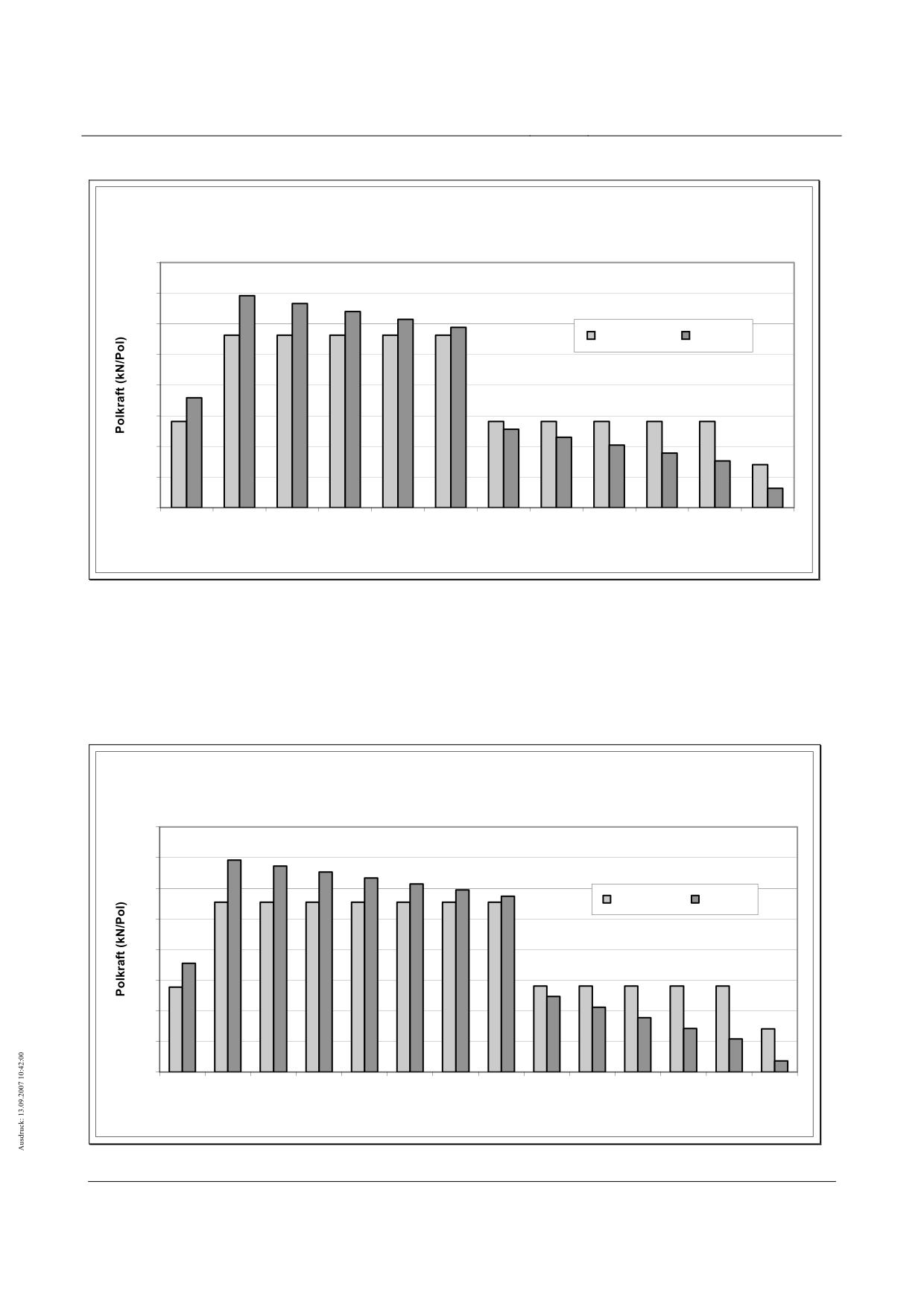
High-speed maglev systems
Maglev Technical Committee
Design principles
Guideway
Regel-Tragmagnete
4.0
3.5
3.0
ohne 30 %
mit 30 %
2.5
2.0
1.5
1.0
0.5
0.0
EP
HP1
HP2
HP3
HP4
HP5
HP6
HP7
HP8
HP9
HP10
EP
Tragmagnetpole
Fig. 180 - Levitation magnet pole forces; example of standard levitation magnets
[Key to diagram:
Regel-Tragmagnete = standard levitation magnets
ohne 30% = less 30%
mit 30% = plus 30%
Polkraft = pole force
Tragmagnetpole = levitation magnet poles]
Bug-/Heck-Tragmagnete
4,0
3,5
3,0
ohne 30 %
mit 30 %
2,5
2,0
1,5
1,0
0,5
0,0
EP
HP1
HP2
HP3
HP4
HP5
HP6
HP7
HP8
HP9
HP10
HP11
HP12
EP
Tragmagnetpole
Fig. 181 - Levitation magnet pole forces; example of front and rear-mounted levitation magnets
Title
High-speed Maglev Systems - Design principles
Guideway - Part II: Design
Doc. no.:
57288
Version
White Paper Issue date
15.02.2007
Page 168
High-speed maglev systems
Maglev Technical Committee
Design principles
Guideway
[Key to diagram:
Bug-/Heck-Tragmagnete = front and rear-mounted levitation magnets
ohne 30% = less 30%
mit 30% = plus 30%
Polkraft = pole force
Tragmagnetpole = levitation magnet poles]
Title
High-speed Maglev Systems - Design principles
Guideway - Part II: Design
Doc. no.:
57288
Version
White Paper Issue date
15.02.2007
Page 169
High-speed maglev systems
Maglev Technical Committee
Design principles
Guideway
Principles for the design of high-speed
maglev systems
Guideway
Part III
Geometry
The author has copyright over this document and all of its annexes.
All rights reserved
Title
High-speed Maglev Systems - Design principles
Guideway - Part III: Geometry
Doc. no.:
41727
Version White Paper Issue date
15.02.2007
Page 1
High-speed maglev systems
Maglev Technical Committee
Design principles
Guideway
Distributor
This document was released for publication by the Guideway Technical Committee.
Title
High-speed Maglev Systems - Design principles
Guideway - Part III: Geometry
Doc. no.:
41727
Version White Paper Issue date
15.02.2007
Page 2
High-speed maglev systems
Maglev Technical Committee
Design principles
Guideway
Revision history
Date of release: 15.02.2007, White Paper published by the Guideway Technical Committee
Title
High-speed Maglev Systems - Design principles
Guideway - Part III: Geometry
Doc. no.:
41727
Version White Paper Issue date
15.02.2007
Page 3
High-speed maglev systems
Maglev Technical Committee
Design principles
Guideway
Table of contents
List of diagrams
Title
High-speed Maglev Systems - Design principles
Guideway - Part III: Geometry
Doc. no.:
41727
Version White Paper Issue date
15.02.2007
Page 4
High-speed maglev systems
Maglev Technical Committee
Design principles
Guideway
General
Object and area of application
This document sets out in detail the generally applicable technical requirements concerning the
guideway geometry of the maglev train system.
These design principles apply to a maglev train in accordance with the General Maglev Systems’
Act.
Document structure
These design principles set out in detail the geometric requirements pertaining to the functional
levels of maglev train support structures.
Requirements concerning the precise positioning of the girders are set out in the Guideway design
principles for high-speed maglev systems - Part IV: Surveying.
The explanatory notes concerning positional deviations, specifications and tolerances assist in a
basic understanding of the construction of a maglev train guideway.
Based on the correlation between the individually stipulated limit values, taking into account the
system as a whole, the limit values may be shifted in either direction. The requirements as per the
Principles concerning the overall system design of high-speed maglev systems are included in the
overall assessment in this regard.
The limit values indicated assist in observing the travel comfort offered by the system as a whole
as well as its technical requirements.
Explanatory note concerning application
The document defines the permitted variations and positional deviations in the functional levels of
the support structures which are to be observed in the equipped and precisely positioned states,
without a live load, the only load coming from the girder’s own weight.
In a further step, taking into account the envisaged manufacturing process, the manufacturing tol-
erances concerning guideway manufacture (the raw materials used in the guideway, its equipment
and assembly) and maintenance shall be derived from this.
Unless expressly noted to the contrary, all data relates to a guideway under a project-specific refe-
rence temperature.
All data relates to the functional levels in the placed, coated state.
The stipulation of requirements in terms of guideway dimensions (e.g. limit values in terms of the
permissible deviation, in combination with the guideway’s deformation) is essentially based on ex-
periences with guideways which have been tested previously and their interaction with magnetic
trains which are driven under test and operational conditions.
The individual permitted variations partly produce overlaps during an overall tolerance assessment.
With additional tolerance stipulations or those which are independent from one another, care must
be taken that the respective individual tolerance is observed or that those stipulations with smaller
tolerance values have priority.
If the document does not list permissible deviations of individual functional levels in terms of form
and position, from the point of view of the system as a whole, there is no inducement to this end.
This case presupposes a manufacturing tolerance as per DIN ISO 2768-1 and DIN ISO 2768-2.
Title
High-speed Maglev Systems - Design principles
Guideway - Part III: Geometry
Doc. no.:
41727
Version White Paper Issue date
15.02.2007
Page 5
High-speed maglev systems
Maglev Technical Committee
Design principles
Guideway
Principles for the design of high-speed maglev systems
This document is part of the documentation relating to high-speed maglev systems con-
sisting of several design principles. The document tree is presented in fig. 1 of the Prin-
ciples concerning the overall system design of high-speed maglev systems.
The primary overall system design documentation and its annexes apply in a uniform manner to
the documentation as a whole:
• Principles concerning the overall system design of high-speed maglev systems, do-
cument number 50630, and its annexes:
• Annex 1: Abbreviations and definitions, document number 67536 [Principles for
the design of high-speed maglev systems - Abbreviations and definitions]
• Annex 2: Acts, Orders, Standards and Guidelines, document number 67539
[Principles for the design of high-speed maglev systems - Standards and guide-
lines]
• Annex 3: Environmental conditions, document number 67285 [Principles for the
design of high-speed maglev systems - The environment]
• Annex 4: Rules for operation (driving and maintenance), document number
69061 [Principles for the design of high-speed maglev systems - Driving and
maintenance]
• Annex 5: Sound, document number 72963 [Principles for the design of high-
speed maglev systems - Sound]
Abbreviations and definitions
The abbreviations and definitions specified in the Principles for the design of high-speed maglev
systems - Abbreviations and definitions - apply.
Acts, Orders, Standards and Guidelines
The normative documents listed in the Principles for the design of high-speed maglev systems -
Standards and guidelines, contain stipulations which, by reference to the Principles for the design
of high-speed maglev systems, become part of the same. Later amendments or revisions to these
publications do not apply to dated, normative documents found in the Principles for the design of
high-speed maglev systems - Standards and guidelines. Where references are not dated, the most
recent version of the normative document referred to applies.
The status of the standards and guidelines to be taken into consideration in a maglev train project
must be laid down in a binding manner specific to the project.
Indicating requirements and their binding nature
The provisions pursuant to DIN 820 were essentially applied when preparing this document.
In the chapters following and the annexes to this document,
• requirements are set out in standard type and
• explanatory notes, standard values and examples are set out in italics
Title
High-speed Maglev Systems - Design principles
Guideway - Part III: Geometry
Doc. no.:
41727
Version White Paper Issue date
15.02.2007
Page 6
High-speed maglev systems
Maglev Technical Committee
Design principles
Guideway
(refer to the Guideway design principles for high-speed maglev systems - Part I: Principle require-
ments).
Title
High-speed Maglev Systems - Design principles
Guideway - Part III: Geometry
Doc. no.:
41727
Version White Paper Issue date
15.02.2007
Page 7
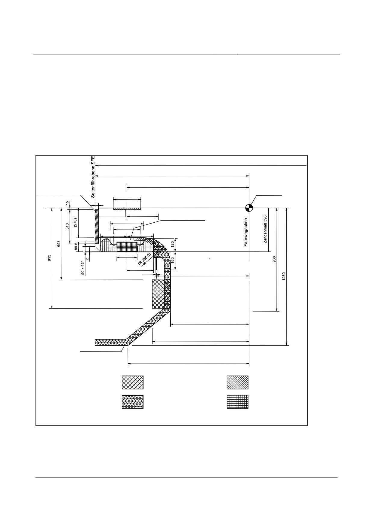
High-speed maglev systems
Maglev Technical Committee
Design principles
Guideway
Clearances for built-in guideway fixtures
The placement clearances for guideway equipment which is specific to high-speed maglev sys-
tems are laid down below in figs. 182, 183 and 184 based on the Principles concerning the overall
system design of high-speed maglev systems. In addition, the dimensions specified in the Annex of
the Guideway design principles for high-speed maglev systems - Part I: Principle requirements, in
relation to standard guideway types must be observed as standard gauges.
A definition of “clearance” is to be found in the Guideway design principles for high-speed maglev
systems - Part IV: Alignment.
Spurweite 2800
1400
1110
Seitenführschiene SFS
Raumkurve
250
min. 30
Gleitebene GE
285
Gleitleiste GL
Statorpaketbefestigung
305
240
max. 240
max. 240
StatorebeneSE
185
240
10
842.5
715
885
Fahrwegumgrenzung
1102
Freiraum für externe
Freiraum für
Bordenergieversorgung
Ortungsbaugruppen
Freiraum für
Freiraum für
LSW Zu- und Ableitung
Motorwicklung
( ) Werte in Klammern sind bauartspezifisch
Fig. 182:
Clearances for the guideway equipment which is specific to high-speed maglev systems and the support
structures
[Key to diagram:
Spurweite = guideway gauge
Seitenführebene = lateral guide level
Title
High-speed Maglev Systems - Design principles
Guideway - Part III: Geometry
Doc. no.:
41727
Version White Paper Issue date
15.02.2007
Page 8
High-speed maglev systems
Maglev Technical Committee
Design principles
Guideway
Seitenführschiene = lateral guide rail
Raumkurve = space curve
Gleitebene = slider level
Gleitleiste = slider strip
Statorpaketbefestigung = stator plate attachment
Fahrwegachse = guideway axis
Zangenmaß = hover clearance
Statorebene = stator level
Fahrwegumgrenzung = guideway boundary
Freiraum für externe Bordenergieversorgung = clearance for external inductive power supply
Freiraum für Ortungsbaugruppen = clearance for location-finding assemblies
Freiraum für LSW Zu- und Ableitung = clearance for LSW supply lines and offtakes
Freiraum für Motorwicklung = clearance for motor winding
Werte in Klammern sind bauartspezifisch = the values in brackets are specific to the design]
Title
High-speed Maglev Systems - Design principles
Guideway - Part III: Geometry
Doc. no.:
41727
Version White Paper Issue date
15.02.2007
Page 9
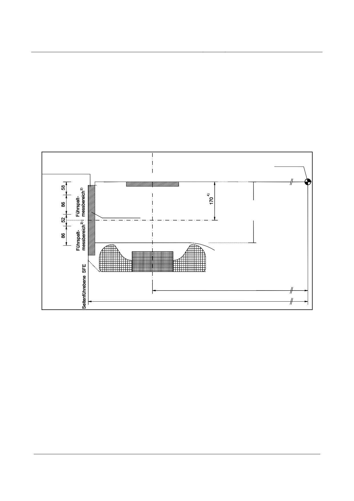
High-speed maglev systems
Maglev Technical Committee
Design principles
Guideway
Explanatory notes to fig. 182:
1) The guideway boundary line describes the maximum feasible wrap-around of the support
structure, including its tolerances.
2) Design-specific deviations from the guideway boundary line are only permitted once they
have been tested for compatibility with the system as a whole.
3) Provision is made for a clearance for securing the guideway equipment between that e-
quipment which is specific to high-speed maglev systems and the support structures. The si-
ze of this clearance depends on the choice of mounting structure and requires a check con-
firming its compatibility with the system as a whole.
Langstatormittachse
Raumkurve
Seitenführschiene SFS
Gleitebene GE
Befestigung
Abstand UK Kragarm
Seitenführschiene-
von GE ist
Trägerkragarm 3)
bauartspezifisch 1)
Statorebene
1110 zur Raumkurve
1400 halbe Spurweite zur Raumkurve
Fig. 183:
Guide span position
[Key to diagram:
Langstatormittachse = centre axis of the longitudinal stator
Raumkurve = space curve
Seitenführschiene = lateral guide rail
Gleitebene = slider level
Führspaltmessbereich = guide span
Befestigung Seitenführschiene-Trägerkragarm = lateral guide rail girder jib boom attachment
Abstand UK Kragarm von GE ist bauartspezifisch = the distance between the bottom side of the jib boom
and the slider level is specific to the design
Seitenführebene = lateral guide level
Statorebene = stator level
zur Raumkurve = in relation to the space curve
halbe Spurweite zur Raumkurve = half the guideway gauge in relation to the space curve]
Explanatory notes to fig. 183:
Title
High-speed Maglev Systems - Design principles
Guideway - Part III: Geometry
Doc. no.:
41727
Version White Paper Issue date
15.02.2007
Page 10
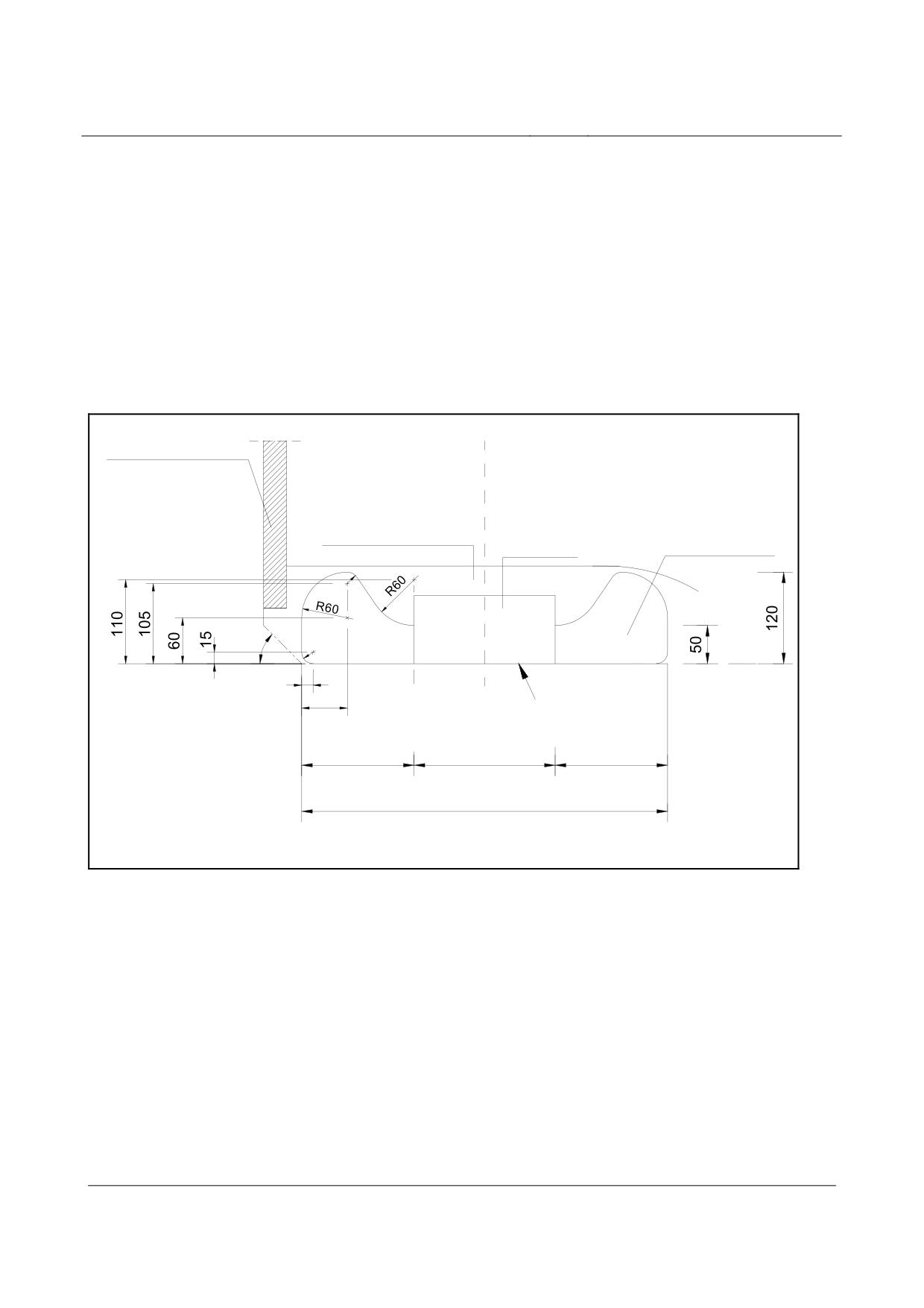
High-speed maglev systems
Maglev Technical Committee
Design principles
Guideway
1) The distance between the bottom side of the jib boom and the slider level is specific to the
design and is established by the type of stator plate mounting and the motor winding hou-
sing.
2) The guide sensor areas depicted correspond to the position when the vehicle is hovering
with a reference loadbearing gap of 10 mm.
3) The mounting for the lateral guide rails and the clearance which is required shall be stipu-
lated in accordance with the particular design.
4) Centre point of the guidance magnets of the hovering vehicle with a reference loadbearing
gap of 10 mm;
Seitenführschiene SFS
Freiraum zur Befestigung
der Statorpakete und für
Freiraum
Erdungsbauteile
1)
Motorwicklung
Statorpaket
R15
45°
R15
15
Statorebene SE
60
147.5
185
147.5
480
Fig. 184:
Long stator winding housing
[Key to diagram:
Seitenführschiene = lateral guide rail
Freiraum zur Befestigung der Statorpakete und für Erdungsbauteile = clearance for attaching the stator pla-
tes and for earthing elements
Statorpaket = stator plate
Freiraum Motorwicklung = clearance for motor winding
Statorebene = stator level]
Explanatory notes to fig. 184:
1)
The motor winding housing depicted also takes into account the space required by the
motor winding cable for the assembly process. The clearances required by the mounting
device lie within the vehicle’s gauge.
Title
High-speed Maglev Systems - Design principles
Guideway - Part III: Geometry
Doc. no.:
41727
Version White Paper Issue date
15.02.2007
Page 11
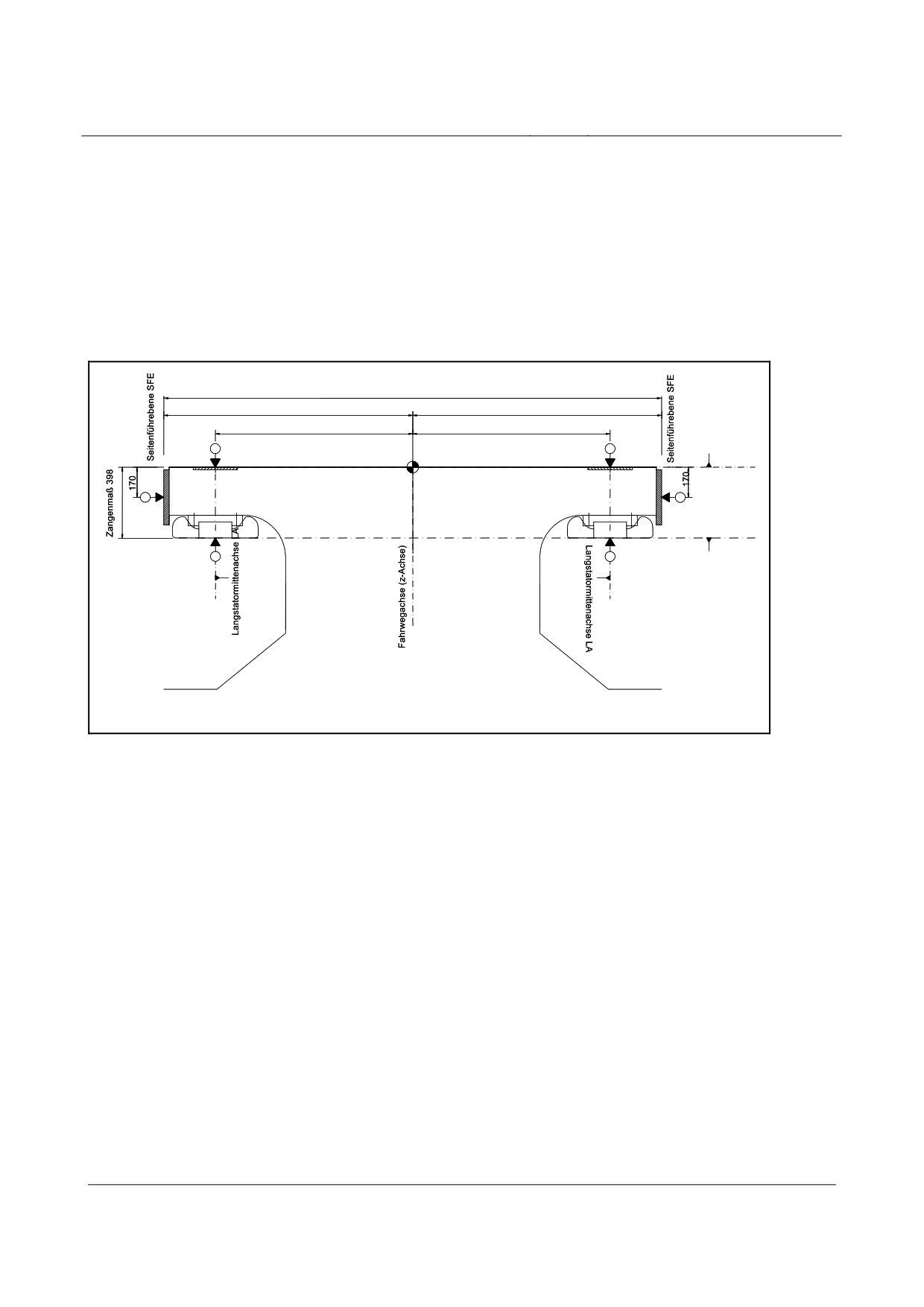
High-speed maglev systems
Maglev Technical Committee
Design principles
Guideway
Dimensional relationships, principal measuring points, reference planes
and influencing variables
Functional levels and principal measuring point
locations
The locations of the functional levels and the associated measuring points in the x, y and z directi-
ons are depicted in figs. 185, 186, 187 and 188.
Spurweite 2800
1400
1400
1110
1110
1
2
Gleitebene GE
y-Achse
5
6
StatorebeneSE
3
4
StatorebeneSE
Spurweite: Messpunkt 5, 6
Zangenmaß: Messpunkt 1, 3 bzw. 2, 4
Fig. 185:
Functional levels and principle measuring points in the y and z directions
[Key to diagram:
Spurweite = guideway gauge
Seitenführebene = lateral guide level
Gleitebene = slider level
Zangenmaß = hover clearance
y-Achse = y-axis
Statorebene = stator level
Langstatormittenachse = centre axis of the longitudinal stator
Fahrwegachse (z-Achse) = guideway axis (z-axis)
Spurweite: Messpunkt 5, 6 = guideway gauge: measuring points 5, 6
Zangenmaß: Messpunkt 1, 3 bzw. 2, 4 = hover clearance: measuring points 1, 3 or 2, 4]
Title
High-speed Maglev Systems - Design principles
Guideway - Part III: Geometry
Doc. no.:
41727
Version White Paper Issue date
15.02.2007
Page 12
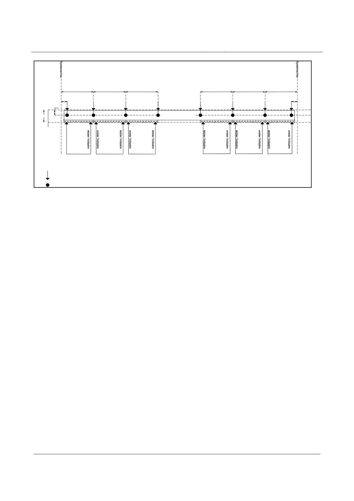
High-speed maglev systems
Maglev Technical Committee
Design principles
Guideway
1032 (Raumkurve)
1032 (Raumkurve)
1032 (Raumkurve)
1032 (Raumkurve)
1032 (Raumkurve)
1032 (Raumkurve)
100
100
170
Gleitebene GE
Zangenmaß 398
Seitenführebene SFE
StatorebeneSE
Messpunkte
Messpunkte
Messpunkte
Messpunkte
Messpunkte
Messpunkte
1.Statorpaket
2.Statorpaket
3.Statorpaket
(n-2).Statorpaket
(n-1).Statorpaket
n.Statorpaket
Bei gekürzten Trägerlängen sind Endmaße entsprechend anzupassen.
Messpunkt
Messpunkt
Fig. 186:
Principal measuring points in the x and z directions
[Key to diagram:
Systemachse = system axis
Raumkurve = space curve
Zangenmaß = hover clearance
Gleitebene = slider level
Seitenführebene = lateral guide level
Statorebene = stator level
letzter Vollzahn = last full-depth tooth
erster Vollzahn = first full-depth tooth
Messpunkte = measuring points
Statorpaket = stator plate
Bei gekürzten Trägerlängen sind Endmaße entsprechend anzupassen = with shorter girder lengths, the final
dimensions shall be adapted accordingly
Messpunkt = measuring point]
The principal measuring point locations in the x direction (refer to fig. 186 for the longitudinal di-
rection) shall be selected such that a measured value for evaluation purposes is at least established
within the system grid dimension of 1032 mm.
Where functional levels which have already been divided up are present, the gap dividing grid must
be observed. In this instance, a measuring point shall be arranged on both sides of the gap.
The first measuring point at the beginning or end of the support structure shall be placed at a uni-
form distance of 100 mm from the system axis and should be durably marked.
Title
High-speed Maglev Systems - Design principles
Guideway - Part III: Geometry
Doc. no.:
41727
Version White Paper Issue date
15.02.2007
Page 13
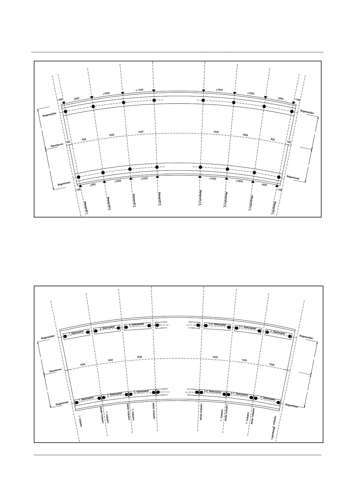
High-speed maglev systems
Maglev Technical Committee
Design principles
Guideway
Seitenführebene SFE
Gleitebene GE
1400
x * 1032
1110
Gleitebene GE
1110
1400
Seitenführebene SFE
Fig. 187:
Principal lateral guide and slider level measuring points
[Key to diagram:
Seitenführebene = lateral guide level
Gleitebene = slider level
Bogenaußen = outer side of the curve
Raumkurve = space curve
Bogeninnen = inner side of the curve
Messprofil = measuring profile]
StatorebeneSE
x * 1032
1110
1110
1110
StatorebeneSE
1110
Fig. 188:
Principal stator level measuring points
Title
High-speed Maglev Systems - Design principles
Guideway - Part III: Geometry
Doc. no.:
41727
Version White Paper Issue date
15.02.2007
Page 14
High-speed maglev systems
Maglev Technical Committee
Design principles
Guideway
[Key to diagram:
Bogenaußen = outer side of the curve
Statorpaket = stator plate
Statorebene = stator level
Raumkurve = space curve
Bogeninnen = inner side of the curve
1. Vollzahn = first full-depth tooth
letzter Vollzahn = last full-depth tooth
Messprofil = measuring profile]
Requirements pertaining to principal measur-
ing points and measured values
The measured values determined for the principal measuring points must allow a representative
statement on the location of the functional level.
This means that measurement procedures and methods which are suitable for determining the
measured value shall be applied which eliminate one-off influences on the measuring result (e.g.
graduated edges, flaws in the material, local surface finishings, anomalies in the coating).
Title
High-speed Maglev Systems - Design principles
Guideway - Part III: Geometry
Doc. no.:
41727
Version White Paper Issue date
15.02.2007
Page 15
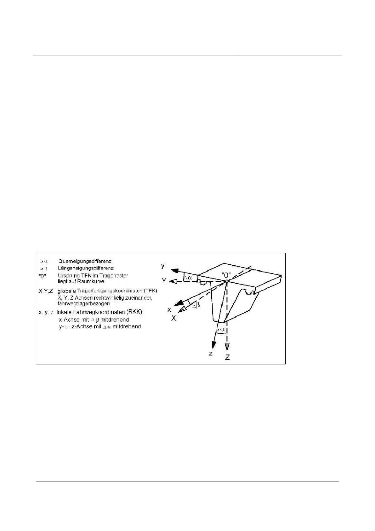
High-speed maglev systems
Maglev Technical Committee
Design principles
Guideway
Coordinate systems
The tolerances given in the document relate to the coordinate axis designations
• y, x, z relate to the space curve coordinate system
(girder-related sector of the space curve with a redefined zero point, see also Chapter 6.6),
and
• Y, X, Z relate to the girder production coordinate system
(machine-related production coordinate system taken into consideration in the design pre-
curvature and production corrections which may be required).
Fig. 189 presents the correlations.
As regards work on the building site (staking out, constructing foundations, precise positioning of
the guideway), the coordinates of the maglev train coordinate system are used.
(refer to the Guideway design principles for high-speed maglev systems - Part IV: Surveying re-
garding the x, y and z coordinates in the maglev train coordinate system)
The beginning and end coordinates of the support structures from the space curve coordinate sys-
tem are transformed into the maglev train coordinate system at the same time via reference points.
Fig. 189:
Geometric correlation between the coordinate systems (girder production coordinate system and local
guideway coordinates)
[Key to diagram:
Querneigungsdifferenz = lateral incline differential
Längsneigungsdifferenz = longitudinal gradient differential
Ursprung TFK im Trägerraster liegt auf Raumkurve = the zero point of the girder fabrication coordinates in
the girder grid lies on the space curve
globale Trägerfertigungskoordinaten (TFK)
X, Y, Z Achsen rechtwinkelig zueinander, fahrwegträgerbezogen =
global girder production coordinates
X, Y, Z axes at right angles to one another, relative to the guideway
lokale Fahrwegkoordinaten (RKK)
x-Achse mit U β mitdrehend
y- u. z-Achse mit U α mitdrehend =
local guideway coordinates
Title
High-speed Maglev Systems - Design principles
Guideway - Part III: Geometry
Doc. no.:
41727
Version White Paper Issue date
15.02.2007
Page 16
High-speed maglev systems
Maglev Technical Committee
Design principles
Guideway
x-axis with U β rotating in the same direction
y- and Z-axes with U α rotating in the same direction]
Title
High-speed Maglev Systems - Design principles
Guideway - Part III: Geometry
Doc. no.:
41727
Version White Paper Issue date
15.02.2007
Page 17
High-speed maglev systems
Maglev Technical Committee
Design principles
Guideway
System and building component lengths
All measurements along the space curve which represent a multiple of 86 mm (this corresponds to a
groove/tooth period according to the Principles concerning the overall system design of high-speed
maglev systems) can be designated system lengths. Support structure lengths are specified when
converting the route into system lengths.
Their actual length (building component length) depends on the design of the functional levels at
the beginning and end of the support structure, as well as the horizontal and vertical radii (see fig.
190).
Bauteillänge (L)
Systemachse
Systemachse
Statorachse (bogenaußen)
Systemlänge des
Fahrwegträgers
(L
)
Sys
Raumkurve
Statorachse (bogeninnen)
R
H
Spalt am Trägerstoß
Fig. 190:
Correlation between building component length and system length
[Key to diagram:
Bauteilänge = building component length
Systemachse = system axis
Statorachse (bogenaußen) = stator axis (outer side of the curve)
Systemlänge des Fahrwegträgers = system length of the support structure
Raumkurve = space curve
Statorachse (bogeninnen) = stator axis (inner side of the curve)
Spalt am Trägerstoß = opening in the girder joint]
Sign stipulations
The sign conventions facilitate a clear interpretation of the maglev train / guideway interface on the
following basis:
When considered from the point of view of increasing chainage (positive x direction), a negative
sign always indicates a deviation towards the space curve, while a positive sign points to a deviati-
on away from the same curve or towards the outside. Regarding the guideway gauge, a negative
sign therefore indicates a reduction, and a positive sign an increase, in the guideway gauge.
When applying the following equations, a clear direction of the deviation from the theoretical posi-
tion is possible by means of the result sign. In the case of vibrations in elements, the displacement
Title
High-speed Maglev Systems - Design principles
Guideway - Part III: Geometry
Doc. no.:
41727
Version White Paper Issue date
15.02.2007
Page 18
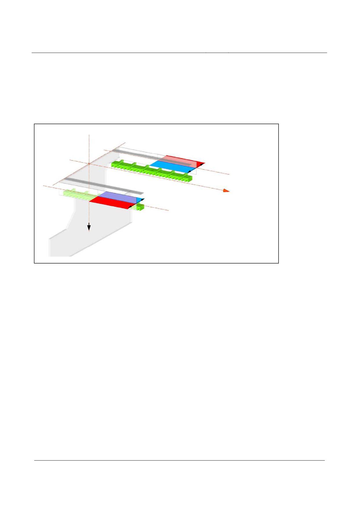
High-speed maglev systems
Maglev Technical Committee
Design principles
Guideway
shall be calculated by extrapolating measuring lines (each time from 2 measuring points) with the
axes of intersection.
• Refer to fig. 191 for the sign convention for lateral guide level displacement:
right side:
∆y
=-y
+
y
Equation 7
i
i+1
left side:
∆y
=
y
-
y
Equation 8
i
i+1
+
Maßbezugslinie SFE
(linke Seite)
-
-
x-Achse
Maßbezugslinie SFE
(rechte Seite)
+
z-Achse
Fig. 191:
Lateral guide level displacement, tolerance zone with sign allocation as per equations 7 and 8
[Key to diagram:
Maßbezugslinie SFE (linke Seite) = zero-datum line, lateral guide level (left side)
Maßbezugslinie SFE (rechte Seite) = zero-datum line, lateral guide level (right side)
x-Achse = x-axis
z-Achse = z-axis]
• Refer to fig. 192 for the sign convention for stator level displacement:
∆z
=-z
+
z
Equation 9
i
i+1
Title
High-speed Maglev Systems - Design principles
Guideway - Part III: Geometry
Doc. no.:
41727
Version White Paper Issue date
15.02.2007
Page 19
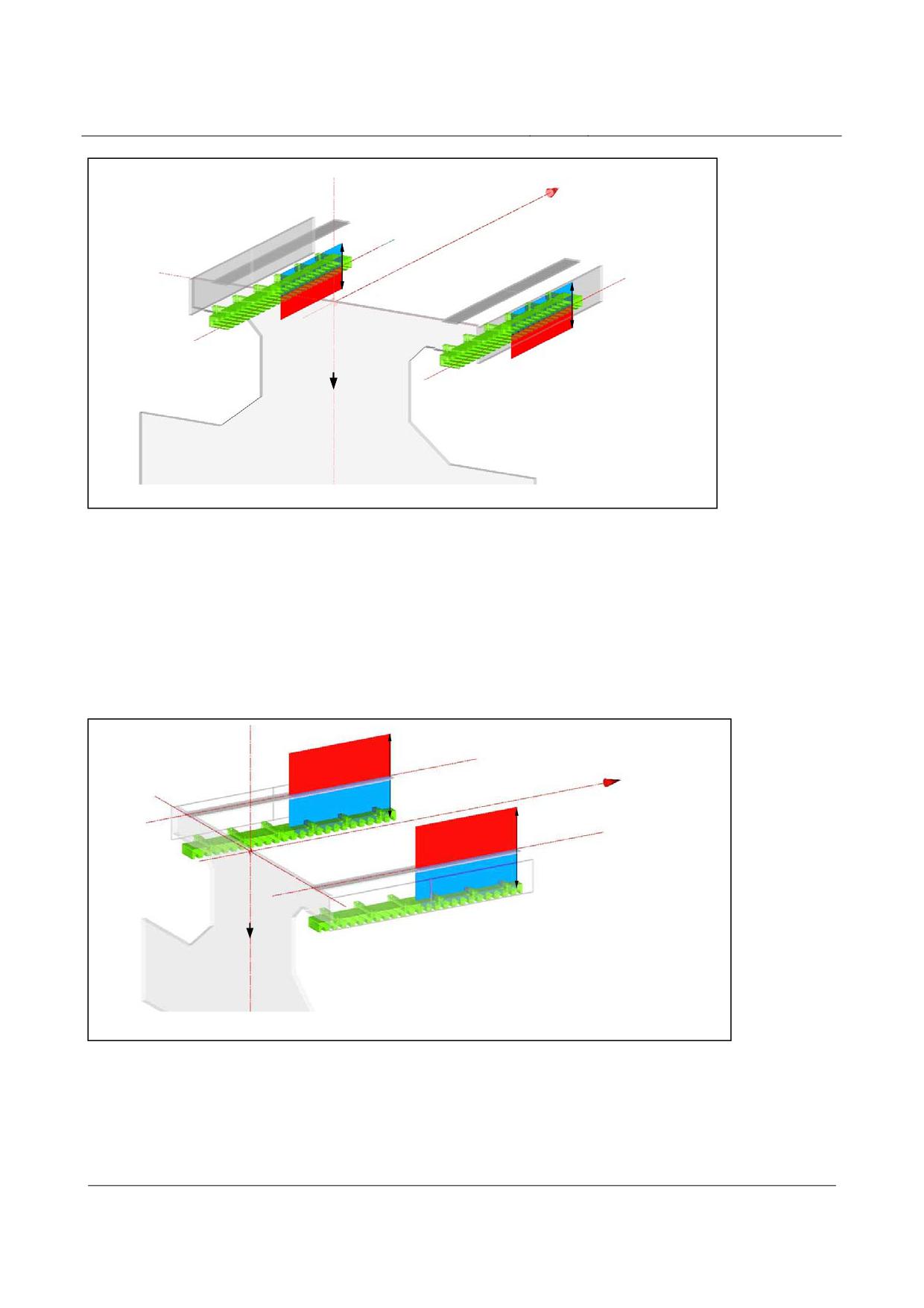
High-speed maglev systems
Maglev Technical Committee
Design principles
Guideway
x-Achse
Maßbezugslinie SE
-
(linke Seite)
-
Maßbezugslinie SE
(rechte Seite)
+
+
z-Achse
Fig. 192:
Stator level displacement, tolerance zone with sign allocation as per equation 3
[Key to diagram:
Maßbezugslinie SE (linke Seite) = zero-datum line, stator level (left side)
Maßbezugslinie SE (rechte Seite) = zero-datum line, stator level (right side)
x-Achse = x-axis
z-Achse = z-axis]
• Refer to fig. 193 for the sign convention for slider level displacement:
∆z
=
z
-
z
Equation 10
i
i+1
+
Maßbezugslinie GE
(linke Seite)
x-Achse
-
+
Maßbezugslinie GE
(rechte Seite)
-
z-Achse
Fig. 193:
Slider level displacement, tolerance zone with sign stipulation as per equation 4
[Key to diagram:
Maßbezugslinie GE (linke Seite) = zero-datum line, slider level (left side)
Maßbezugslinie GE (rechte Seite) = zero-datum line, slider level (right side)
x-Achse = x-axis
z-Achse = z-axis]
Title
High-speed Maglev Systems - Design principles
Guideway - Part III: Geometry
Doc. no.:
41727
Version White Paper Issue date
15.02.2007
Page 20
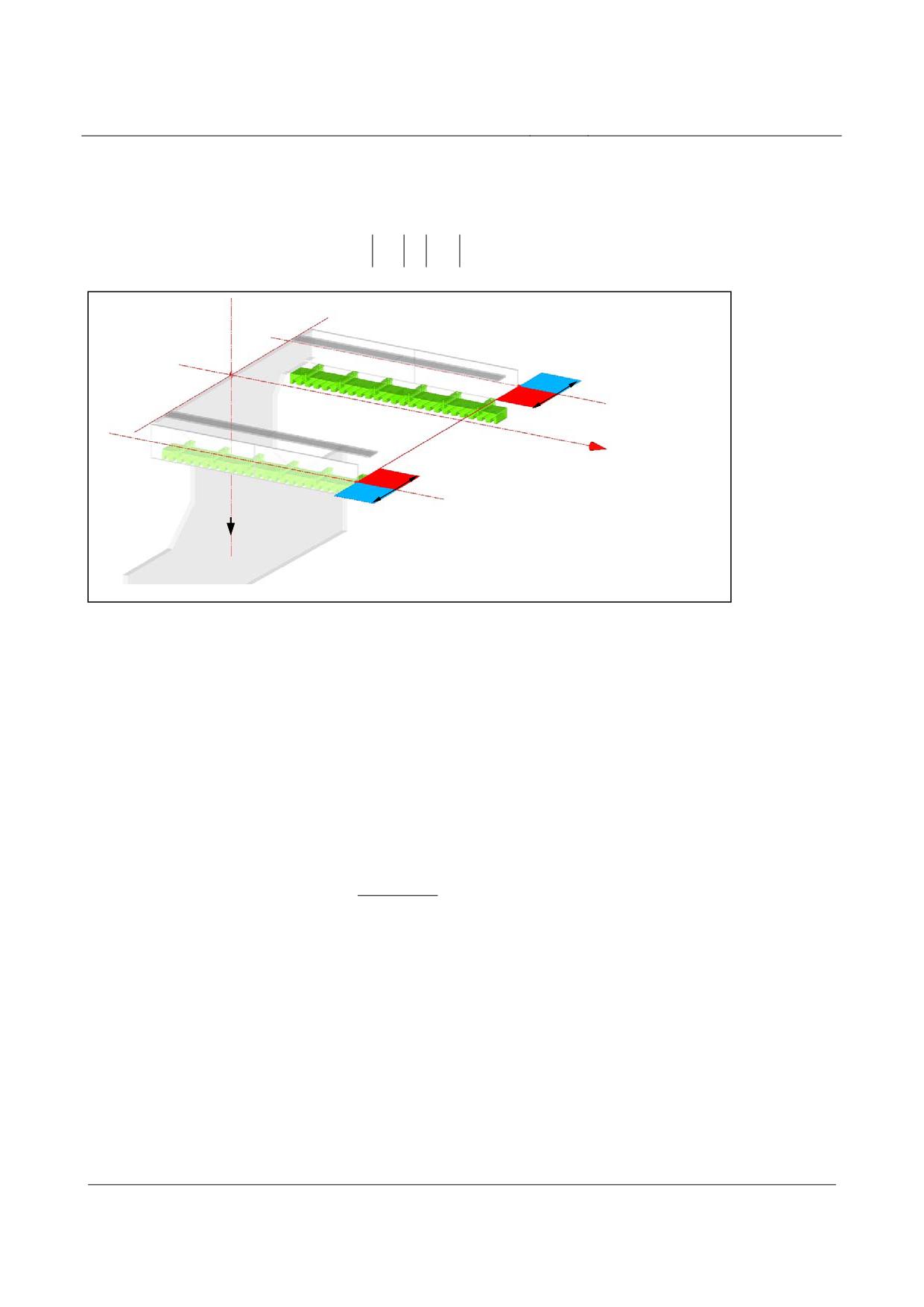
High-speed maglev systems
Maglev Technical Committee
Design principles
Guideway
• Refer to fig. 194 for the sign convention for altering the guideway gauge (S):
Equation 11
∆y
=-S
+
S
;
S
=
y
+
y
s
i
i+1
i
i
i
1
2
+
Maßbezugslinie SFE
(linke Seite)
-
-
x-Achse
Maßbezugslinie SFE
(rechte Seite)
z-Achse
+
Fig. 194:
Altering the guideway gauge, tolerance zones with sign stipulation as per equation 11
[Key to diagram:
Maßbezugslinie SFE (linke Seite) = zero-datum line, lateral guide level (left side)
Maßbezugslinie SFE (rechte Seite) = zero-datum line, lateral guide level (right side)
x-Achse = x-axis
z-Achse = z-axis]
• The sign convention for the gradient-altering criterion of the lateral guide level within the
girder, and at the girder joint and element transition, is extrapolated in accordance with
equation 14 while observing the intervals between measuring points. Refer to fig. 195 for
the graphic representation of the sign convention:
right side:
⎡
⎛
y
+
y
⎞⎤
i-1
i
+1
Equation 12
NGK
=
2*⎢-y
+
SFE
i
⎜
⎟
⎥
⎣
⎝
2
⎠
⎦
left side:
⎡
⎛
y
+
y
⎞⎤
i-1 i+1
Equation 13
NGK
=
2*⎢y
−
SFE
i
⎜
⎟
⎥
⎣
⎝
2
⎠
⎦
Title
High-speed Maglev Systems - Design principles
Guideway - Part III: Geometry
Doc. no.:
41727
Version White Paper Issue date
15.02.2007
Page 21
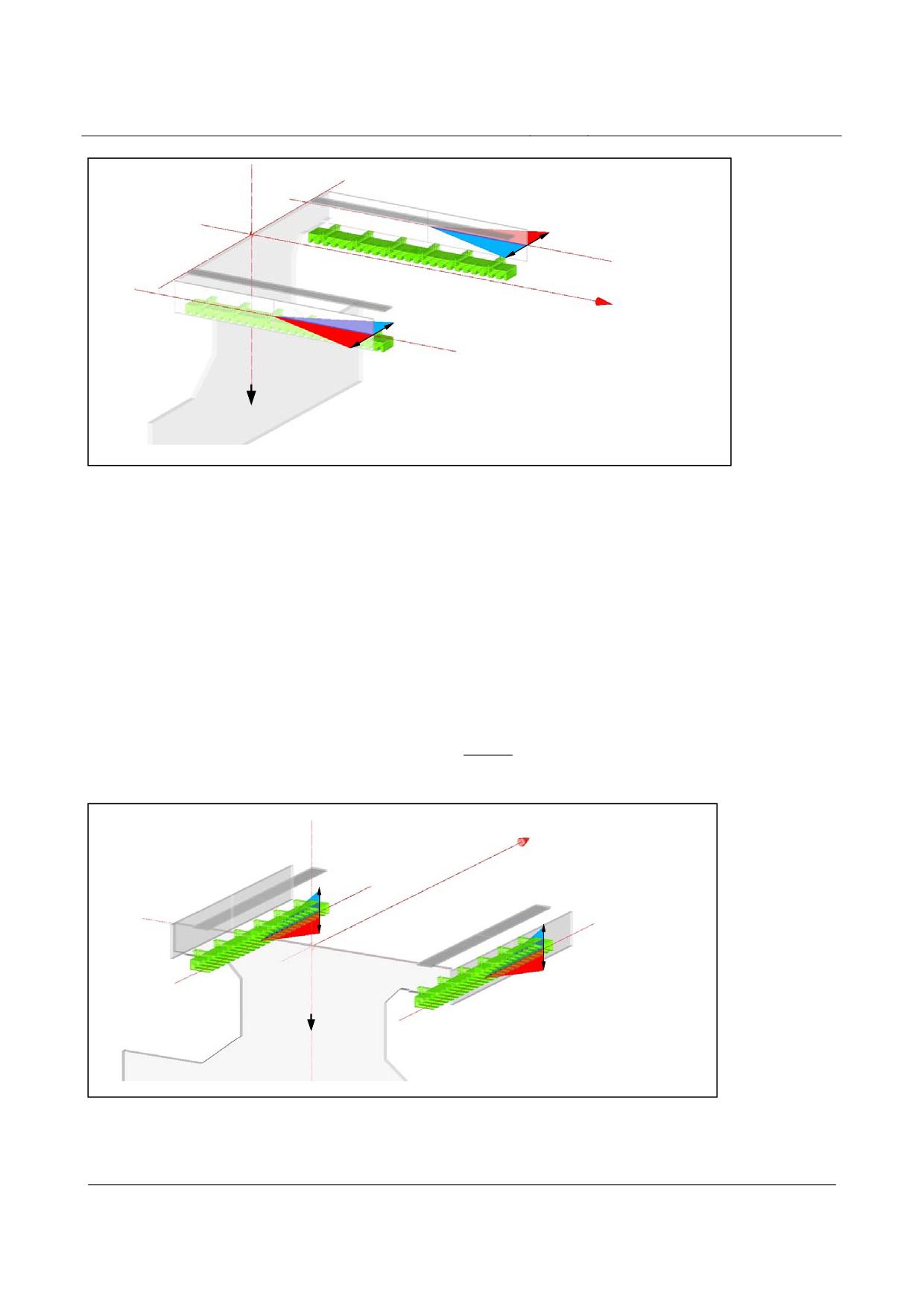
High-speed maglev systems
Maglev Technical Committee
Design principles
Guideway
+
Maßbezugslinie SFE
(linke Seite)
-
-
x-Achse
Maßbezugslinie SFE
(rechte Seite)
+
z-Achse
Fig. 195:
Gradient-altering criterion of the lateral guide level, tolerance zones and sign stipulation as per equations
12 and 13
[Key to diagram:
Maßbezugslinie SFE (linke Seite) = zero-datum line, lateral guide level (left side)
Maßbezugslinie SFE (rechte Seite) = zero-datum line, lateral guide level (right side)
x-Achse = x-axis
z-Achse = z-axis]
• The sign convention for the gradient-altering criterion of the stator level over four measu-
ring points (first and last full-depth tooth of the stator plate numbered continuously (z1, z2, z3
and z4)). Refer to fig. 196 for the graphic representation of the sign:
1000
Equation 14
NGK
=⎣(z
-
z
)+
(
z
−
z
)
⎦
*
SE
1
2
4
3
860
e
x-Achs
-
Maßbezugslinie SE
(linke Seite)
-
Maßbezugslinie SE
(rechte Seite)
+
+
z-Achse
Fig. 196:
Gradient-altering criterion of the stator level, tolerance zones with sign allocation as per equation 14
[Key to diagram:
Maßbezugslinie SE (linke Seite) = zero-datum line, stator level (left side)
Title
High-speed Maglev Systems - Design principles
Guideway - Part III: Geometry
Doc. no.:
41727
Version White Paper Issue date
15.02.2007
Page 22
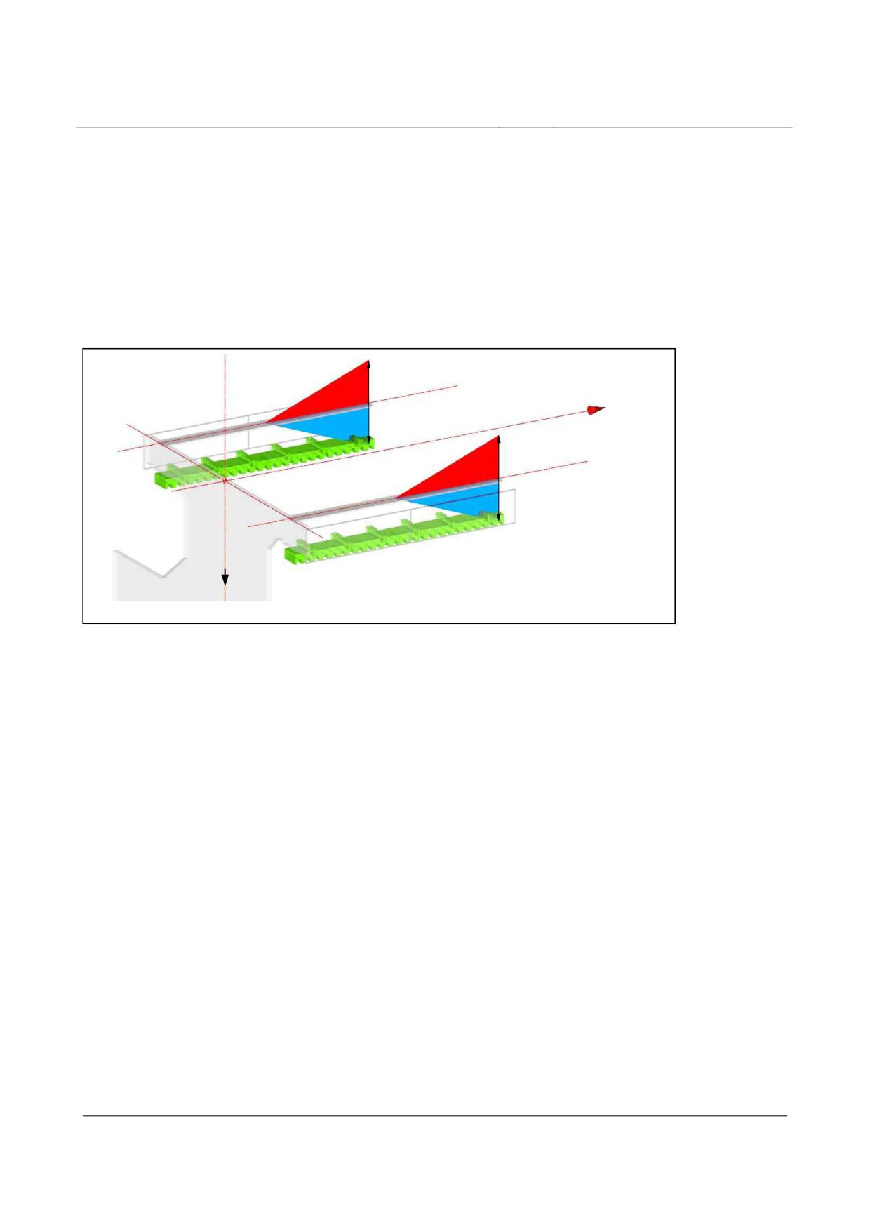
High-speed maglev systems
Maglev Technical Committee
Design principles
Guideway
Maßbezugslinie SE (rechte Seite) = zero-datum line, stator level (right side)
x-Achse = x-axis
z-Achse = z-axis]
• Refer to fig. 197 for the sign convention for the gradient-altering criterion of the slider le-
vel:
⎡
⎛
z
+
z
⎞⎤
i-1 i+1
Equation 15
NGK
=
2*
z
-
GLE
⎢
i
⎜
⎟⎥
⎣
⎝
2
⎠⎦
+
Maßbezugslinie GE
(linke Seite)
x-Achse
-
+ Maßbezugslinie GE
(rechte Seite)
-
z-Achse
Fig. 197:
Gradient-altering criterion of the slider level, tolerance zones with sign allocation as per equation 15
[Key to diagram:
Maßbezugslinie GE (linke Seite) = zero-datum line, slider level (left side)
Maßbezugslinie GE (rechte Seite) = zero-datum line, slider level (right side)
x-Achse = x-axis
z-Achse = z-axis]
Title
High-speed Maglev Systems - Design principles
Guideway - Part III: Geometry
Doc. no.:
41727
Version White Paper Issue date
15.02.2007
Page 23
High-speed maglev systems
Maglev Technical Committee
Design principles
Guideway
Definitions and stipulations for tolerances and
positional deviations
The tolerances and positional deviations described below relate exclusively to the girder production
coordinate system.
Assuming a bearing arrangement, a distinction is drawn between simple beams, two-span beams
and multiple span girders as well as gauge change devices.
When stipulating the tolerance zones, guideway plates are treated as simple beams.
In the diagrams which follow, the x-axis of the coordinate system mirrors the layout of the
space curve.
Design precurvature
The design precurvature is designed to compensate the deflection of the support structure in the z
direction as a result of the live load (mean vehicle weight under normal load conditions as per the
Guideway design principles for high-speed maglev systems - Part II: Dimensioning) and also taking
into account the project-specific prevailing temperature differentials in the guideway cross-section
(change in temperature between the top and bottom booms) under operating conditions. In the case
of concrete girders, where necessary, consideration must be given to the creep and shrinkage cha-
racteristics over the first 25-30 years (refer to the Guideway design principles for high-speed
maglev systems - Part II: Dimensioning).
The aim as regards the guideway functional levels arranged in the z direction is that the reference
surface is as flat as possible during operation. In this connection, the progression of the design
precurvature generally relates to the position of the stator level under operating conditions (the
theoretical position in the operating state corresponds in this connection to the progression of the
space curve).
For determining the share of deformation to be taken into consideration as a result of the guideway
temperature differential, a project-specific temperature change shall be stipulated (taking into ac-
count, inter alia, the design of the girder and the material used in its construction, the typical day-
time temperature distribution within the girder and the gradient).
In the load-free theoretical position, for instance, during production (no live load, uniform building
component temperature [∆ T = 0 K], the building component temperature = the project-specific
reference temperature), the functional levels arranged in the z direction (stator, slider levels) are
therefore deflected upwards (see fig. 198, exception: refer to fig. 203 for stipulating the gauge
change devices).
Title
High-speed Maglev Systems - Design principles
Guideway - Part III: Geometry
Doc. no.:
41727
Version White Paper Issue date
15.02.2007
Page 24
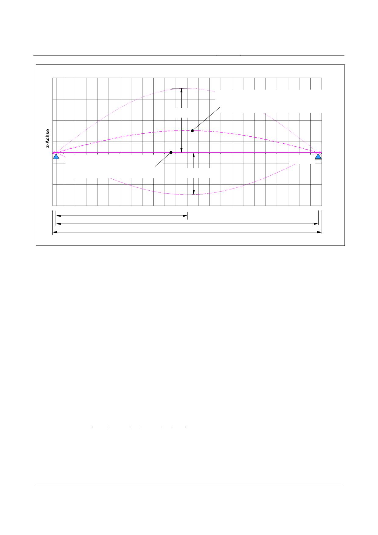
High-speed maglev systems
Maglev Technical Committee
Design principles
Guideway
Soll-Vorkrümmung (z i, Soll );
entspr. Soll-Lage der Funktionsebene,
bei ∆T= 0 K im unbelasteten Zustand
fz, Fzg
Soll-Lage
x-Achse
der Statorebene im Betriebszustand
(entspr. Verlauf der Raumkurve)
f
z, ∆T 0
LSt/ 2
St
LSt
L
Fig. 198:
Design precurvature and its proportions (the diagram does not take account of creep and shrinkage charac-
teristics)
[Key to diagram:
Soll-Vorkrümmung (z i / soll); entspr. Soll-Lage der Funktionsebene, bei UT= 0 K im unbelasteten Zustand =
design precurvature (z i / soll); corresponding to the theoretical position of the functional level, where UT = 0 K
in the load-free state
Soll-Lage der Statorebene im Betriebszustand (entspr. Verlauf der Raumkurve) = theoretical position of the
stator level in the operating state (corresponding to the progression of the space curve)
x-Achse = x-axis
z-Achse = z-axis]
Design precurvature in the case of simple beams
Between the girder supports, the progression of the design precurvature can be determined in the
case of simple beams as per equation 16 (see also fig. 201).
To stipulate the progression of the design precurvature in the support structure areas from the sup-
port axes up to the beginning or end of the girder, tangents are laid at the design precurvature curve
determined using support axis x values.
The progression of the design precurvature in relation to the z coordinates, by way of example:
3
4
384
⎛
x
2*x
x
⎞
i
i
i
Equation 16
z
=
z
*
*
-
+
[mm]
i,Soll
max
⎜
3
4
⎟
120
L
L
L
⎝
St
St
St
⎠
Limit values for zmax = fz, Fzg - fz, ∆T o as per the Guideway design principles for high-speed
maglev systems - Part II: Dimensioning
Title
High-speed Maglev Systems - Design principles
Guideway - Part III: Geometry
Doc. no.:
41727
Version White Paper Issue date
15.02.2007
Page 25
High-speed maglev systems
Maglev Technical Committee
Design principles
Guideway
Design precurvature in the case of two-span beams
In the case of two-span beams with the same spans, the progression of the design precurvature can
be determined for each span from the existing, calculated maximum deflection of the beam where
both spans are subjected to loads depending on the length of the beam and its rigidity as per equati-
on 17 (see also fig. 202).
The maximum deflection each time is 0.421* L St viewed from the section support axis.
To stipulate the progression of the design precurvature in the areas of the guideway from the section
support axes up to the beginning or end of the girder, tangents are laid at the design precurvature
curve determined using support axis x values.
The progression of the design precurvature of two-span beams with unequal spans or different gir-
der section rigidities shall be determined in the same way for every Li.
The progression of the design precurvature in relation to the z coordinates, by way of example:
3
4
⎛
⎞
185
x
3*x
2*x
i
i
i
Equation 17
z
=
z
*
*⎜
-
+
⎟
[mm]
i,Soll
max
3
4
⎜
⎟
48
L
L
L
⎝ Sti
St
i
St
i
⎠
Limit values for zmax = fz, Fzg - fz, ∆T o as per the Guideway design principles for high-speed maglev
systems - Part II: Dimensioning
Design precurvature in the case of multiple span girders and gauge change devices
In the case of multiple span girders, a decision shall be reached on taking into account the design
precurvature depending on the elastic line which is adjusted and the resulting deflections in the z
direction and the end tangent angle at the beginning and end of the girder.
In the case of gauge change devices, as a rule, no design precurvature is taken into consideration.
Long-wave deviation
The definition of long-wave deviation is based, in principle, on the elastic line characteristic of the
support structure to which a maximum permitted excursion (“deflection”) is assigned in both direc-
tions (+/-) for each section under consideration.
The following stipulations are laid down as regards the upper and lower tolerance zone limits in
terms of the long-wave deviation from the theoretical position (see also figs. 201, 202 and 203):
• In the case of simple and two-span beams, the x value of the maximum long-wave deviation
is consistent with the x value of the maximum theoretical guideway deformation as a result
of the impact of loads.
• In the case of simple and two-span beams, the progression from the maximum point to the
beginning or end of the support structure may be described by equations 18 and 19 respecti-
vely.28
As regards a design precurvature in the functional level which is to be taken into considera-
tion, the limits can be determined in a simplified manner according to equation 20.
• In the case of simple and two-span beams, the functions of the theoretical elastic lines bet-
ween the support locations are used as a basis for determining the tolerance band for long-
Title
High-speed Maglev Systems - Design principles
Guideway - Part III: Geometry
Doc. no.:
41727
Version White Paper Issue date
15.02.2007
Page 26