Design Principles High-speed Maglev System. Information (MSB, 2007) - page 10
High-speed Maglev system
Maglev Technical Committee
Design principles
Guideway
- Areas with external on-board energy supply (with definition of the cable structures on the
substructures).
The system technical guideway equipment list should be complemented with additional information for the edge of the
track in a project specific way (such as e.g. radio aerials, cable routings, protective structures etc).
Documents for maintenance
see /MSB AG-FW IH/
Title
High-speed Maglev system design principles
Guideway Part I - Overriding requirements
Doc.no.:
57284
Version
White paper
Issue date
15.02.2007
Page 72
High-speed Maglev system
Maglev Technical Committee
Design principles
Guideway
Annex I-A Maximum dimensions for guideway superstructures
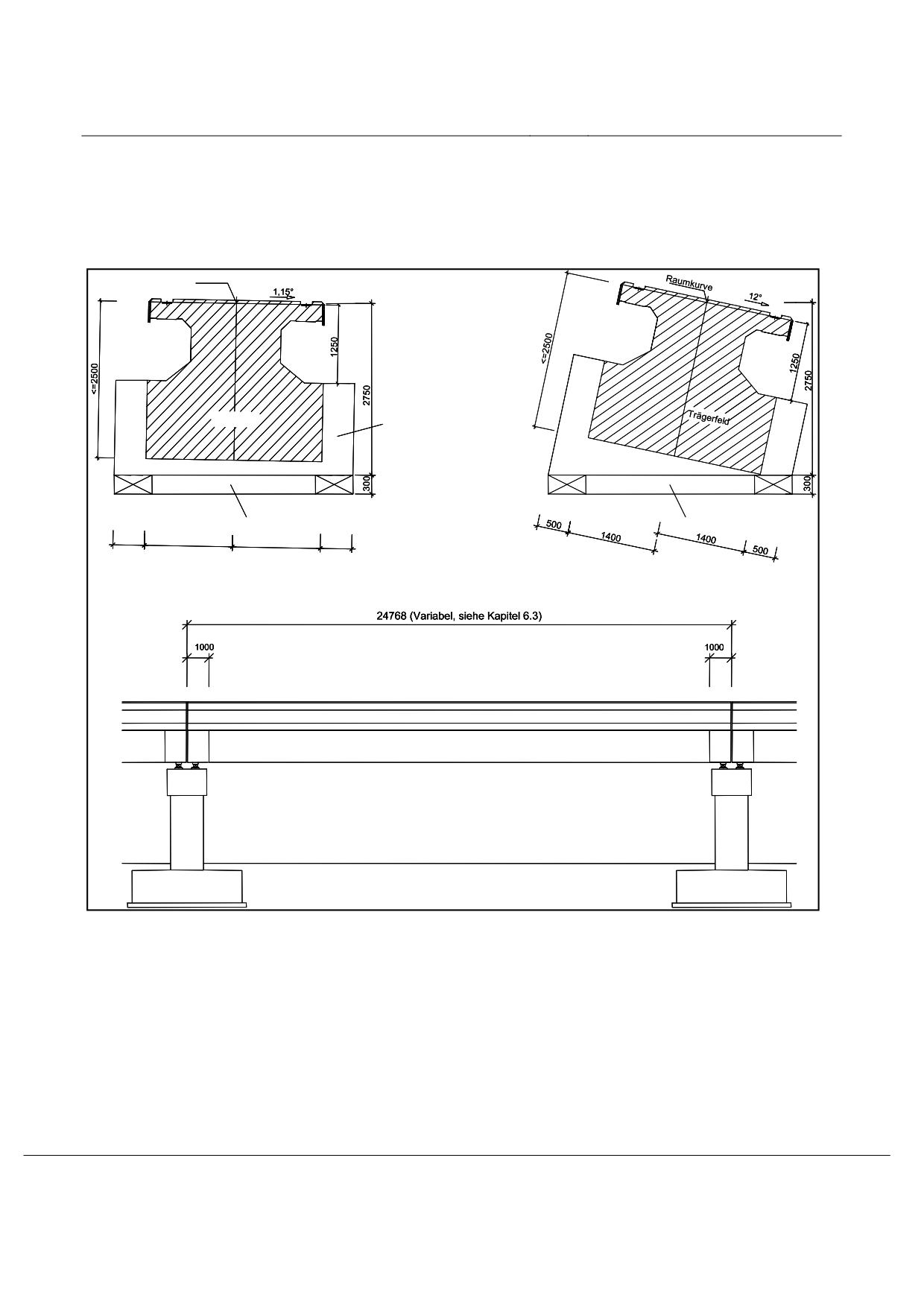
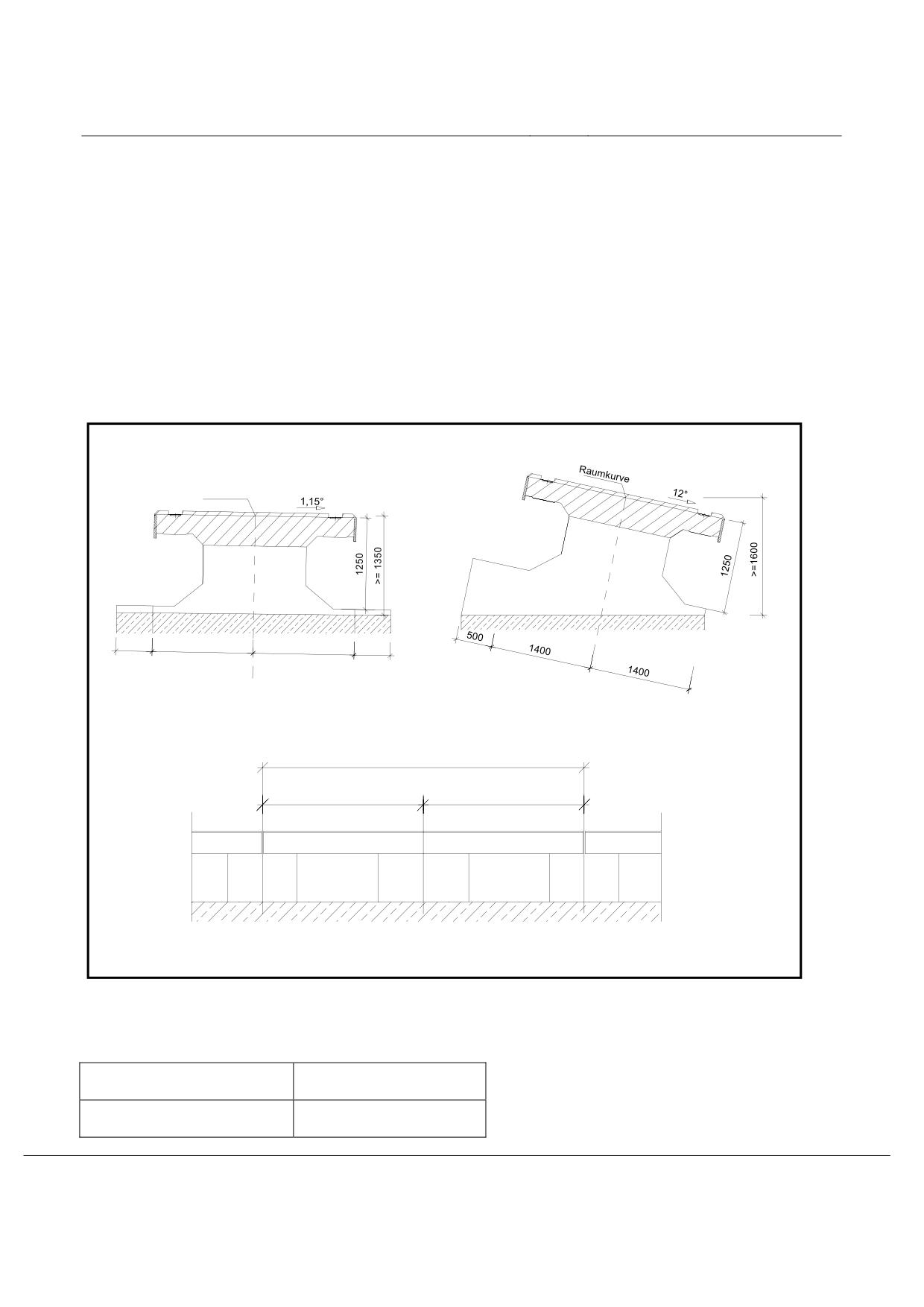
In the following figures the maximum dimensions for guideway superstructures of the standard guideway
types I, II and III are given. These dimensions are to be taken into account in the development of new
guideway superstructures along with the requirements for clearance following Figure 106.
Raumkurve
Trägerfeld
Auflagerbereich
(Lagerpratzen)
Auflagerbereich
(Lagerpratzen)
mögl. Einbaubereich
mögl. Einbaubereich
für Lager
für Lager
500
1400
1400
500
Figure 111: Maximum sectional dimension for standard guideway type I (example)
Title
High-speed Maglev system design principles
Guideway Part I - Overriding requirements
Doc.no.:
57284
Version
White paper
Issue date
15.02.2007
Page 73
High-speed Maglev system
Maglev Technical Committee
Design principles
Guideway
Raumkurve
Space curve
Trägerfeld
Beam field
Auflagerbereich (Lagerpratzen)
Support area (support paws)
Mögl. Einbaubereich für Lager
Possible installation area for supports
(Variabel, siehe Kapitel 6.3)
(Variable, see chapter 6.3)
Figure 112: Maximum sectional dimension for standard guideway type II (example)
Title
High-speed Maglev system design principles
Guideway Part I - Overriding requirements
Doc.no.:
57284
Version
White paper
Issue date
15.02.2007
Page 74
High-speed Maglev system
Maglev Technical Committee
Design principles
Guideway
Raumkurve
Auflager-
Auflager-
bereich
bereich
500
1400
1400
500
6192 (variabel, siehe Kapitel 6.3 (14))
3096
3096
Figure 113: Maximum sectional dimension for standard guideway type III (example)
Raumkurve
Space curve
Auflagerbereich (Lagerpratzen)
Support area (support paws)
Title
High-speed Maglev system design principles
Guideway Part I - Overriding requirements
Doc.no.:
57284
Version
White paper
Issue date
15.02.2007
Page 75
High-speed Maglev system
Maglev Technical Committee
Design principles
Guideway
(Variabel, siehe Kapitel 6.3)
(Variable, see chapter 6.3)
Title
High-speed Maglev system design principles
Guideway Part I - Overriding requirements
Doc.no.:
57284
Version
White paper
Issue date
15.02.2007
Page 76
High-speed Maglev system
Maglev Technical Committee
Design principles
Guideway
Annex I-B Arrangement of the maglev train specific guideway equip-
ment (informative)
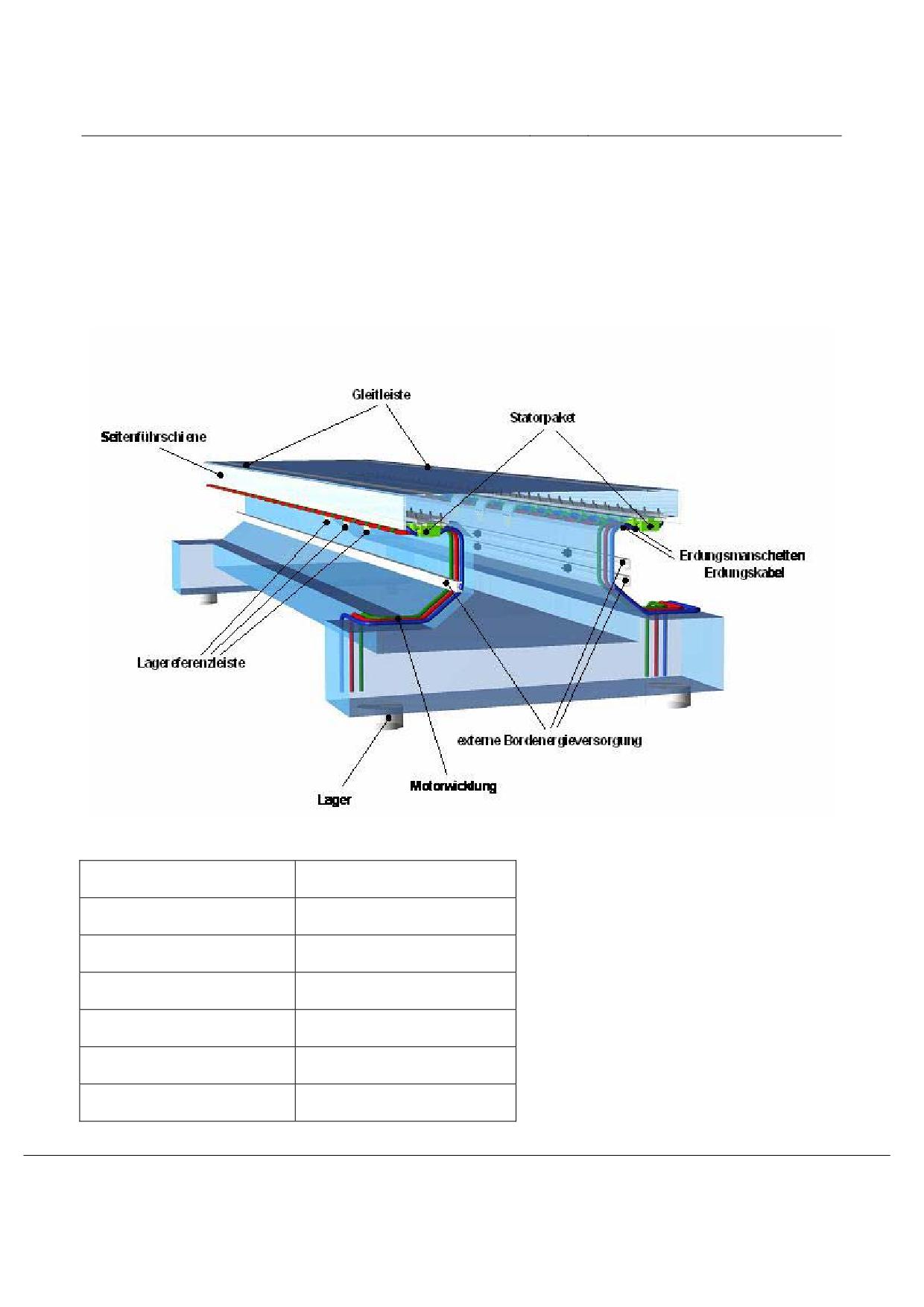
In figure 114 the arrangement of the maglev specific guideway equipment on the guideway beam is shown
as an example.
Figure 114: Arrangement of the maglev train specific guideway equipment on the guideway beam
Seitenführschiene
Lateral guidance rail
Gleitleiste
Sliding strip
Statorpaket
Stator pack
Erdungsmanschetten
Earth sleeves
Erdungskabel
Earth cable
Externe Bordenergieversorgung
External on-board energy supply
Motorwicklung
Motor winding
Title
High-speed Maglev system design principles
Guideway Part I - Overriding requirements
Doc.no.:
57284
Version
White paper
Issue date
15.02.2007
Page 77
High-speed Maglev system
Maglev Technical Committee
Design principles
Guideway
Lagereferenzleiste
Position reference rail
Lager
support
Title
High-speed Maglev system design principles
Guideway Part I - Overriding requirements
Doc.no.:
57284
Version
White paper
Issue date
15.02.2007
Page 78
High-speed Maglev system
Maglev Technical Committee
Design principles
Guideway
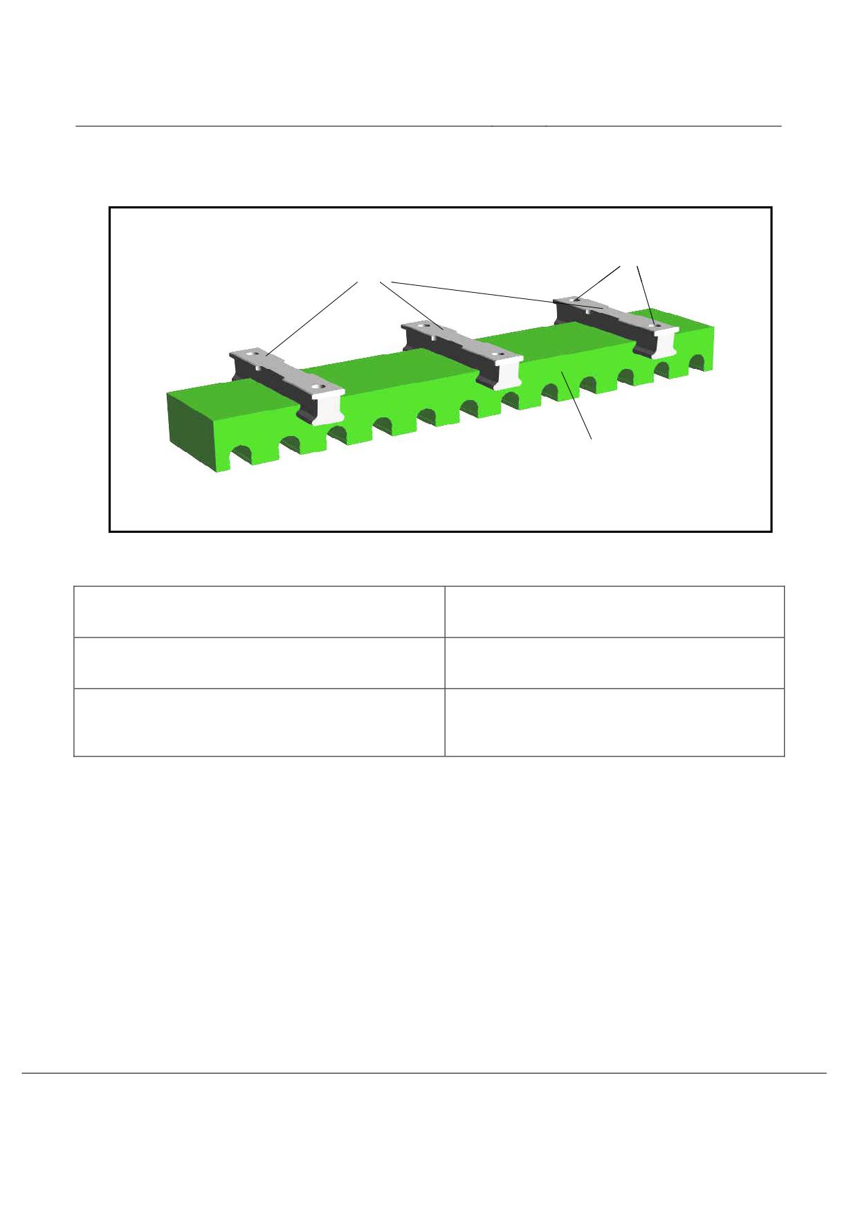
Annex I-C Stator pack and motor winding (informative)
Bohrungen für die Schrauben
Nuttraversen als integrierte
zur Befestigung an den Fahr-
Befestigungselemente inkl.
wegüberbauten
Oberflächenbeschichtung
Elektroblechpaket mit Nuten zur Aufnahme der
Motorwicklung und der Nuttraversen inkl.
Oberflächenbeschichtung
Figure 115: Example of a completed stator pack
Nuttraversen als integrierte Befestigungselemente inkl. Ober-
Groove cross beams as integrated securing elements
flächenbeschichtung
including surface coating
Bohrungen für die Schrauben zur Befestigung an den Fahr-
Bores for the bolts for securing to the guideway su-
wegüberbauten
perstructure
Elektroblechpaket mit Nuten zur Aufnahme der Motorwick-
Electro laminated core with slots for accepting the
lung und der Nuttraversen inkl. Oberflächen beschichtung
motor winding and the groove cross beams including
surface coating
Title
High-speed Maglev system design principles
Guideway Part I - Overriding requirements
Doc.no.:
57284
Version
White paper
Issue date
15.02.2007
Page 79
High-speed Maglev system
Maglev Technical Committee
Design principles
Guideway
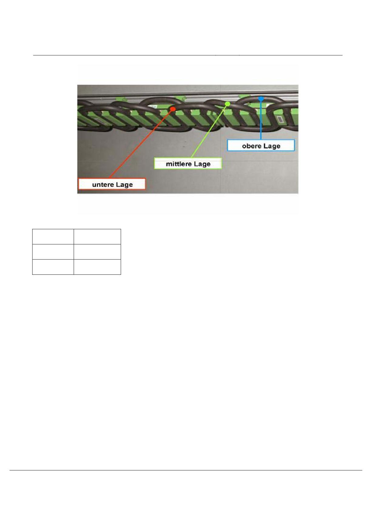
Figure 116: Example of a 3 phase motor winding
Untere Lage
Lower position
Mittlere Lage
Middle position
Obere Lage
Upper position
Title
High-speed Maglev system design principles
Guideway Part I - Overriding requirements
Doc.no.:
57284
Version
White paper
Issue date
15.02.2007
Page 80
High-speed Maglev system
Maglev Technical Committee
Design principles
Guideway
Annex I-D Diverse redundant securings for stator packs (examples)
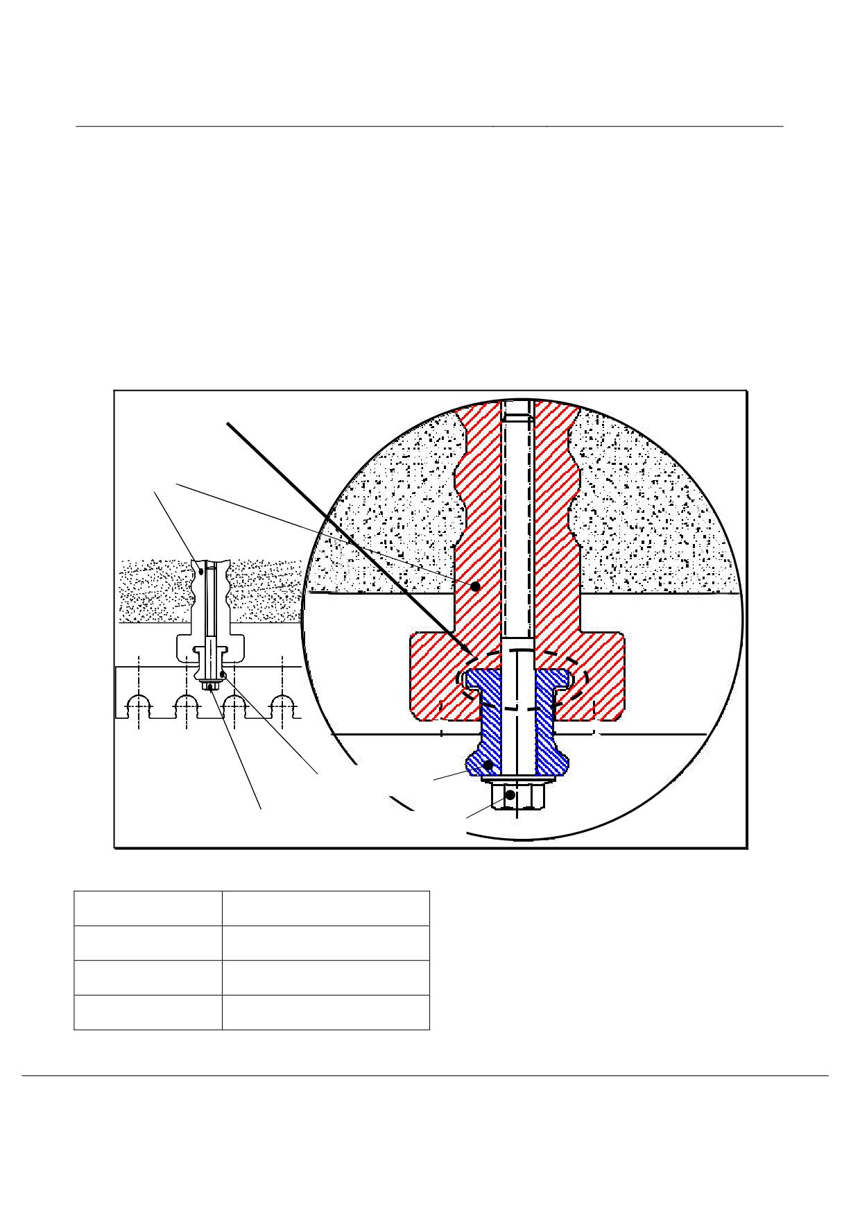
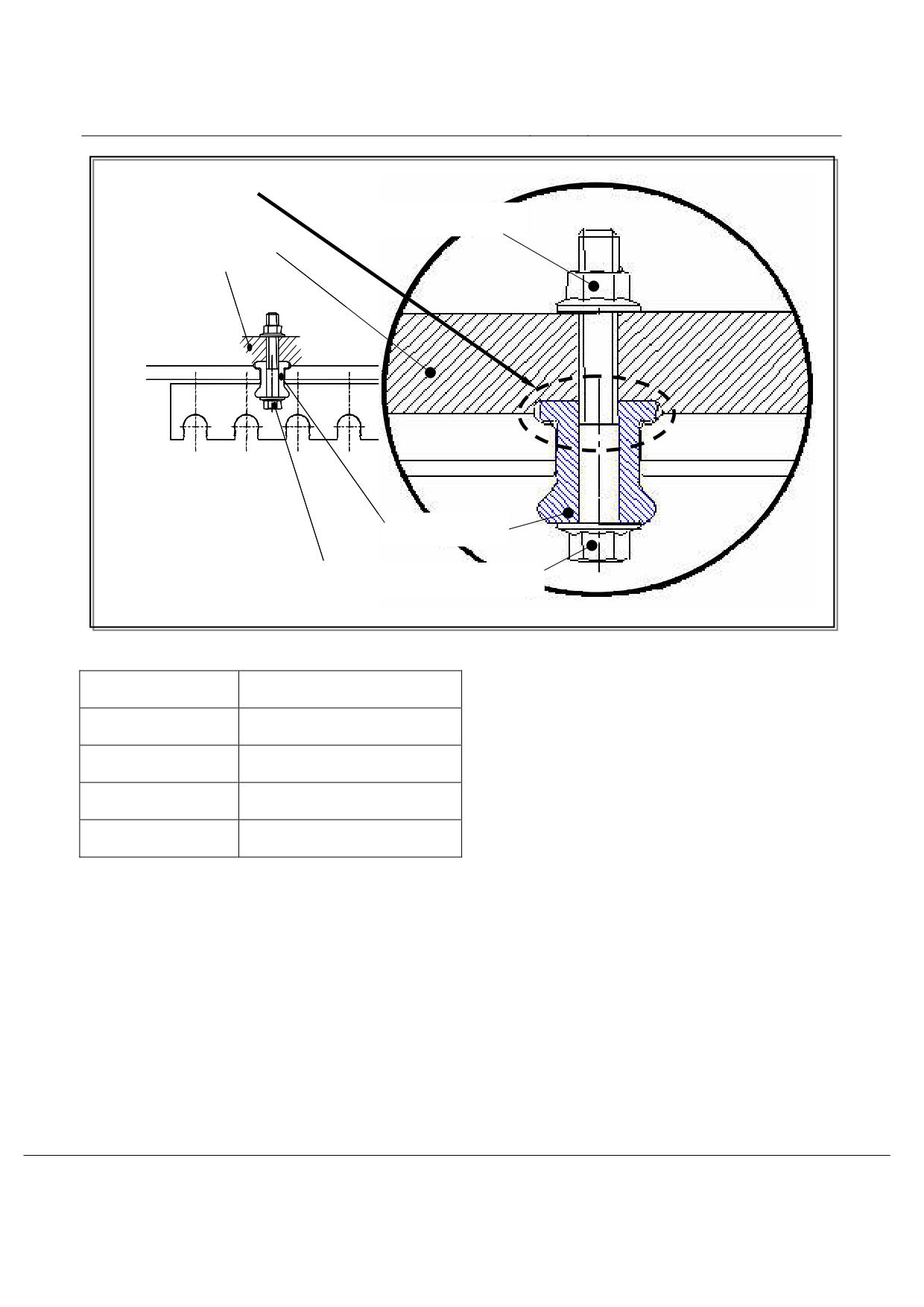
In the following figures examples for diverse redundant securings for stator packs are shown. The solutions
shown (figure 117 and figure 118) are used in prototypes of the Transrapid test facility in Emsland (TVE) and
in the Shanghai stretch.
The primary fixing in these solutions consists of a pre-tensioned bolt (primary fixing) The redundancy con-
sists of the grooves by the cantilever arm and the cantilever arms of the groove cross beams by the stator
pack. If bolts fail the stator pack settles on the grooves by the cantilever arm. The play between the cantile-
ver arms of the groove cross beams and the surfaces of the fixings by the beams is such that automatic de-
tection in accordance with “design basis guideway part III” /MSB AG-FW GEO/ and “design basis guideway
part IV” /MSB AG-FW IH/ is possible.
Redundanzbefestigung
Insert
Nuttraverse
Befestigungsschraube
Figure 117: Example of a diverse redundant stator pack fixing on a concrete cantilever arm
Insert
insert
Redundanzbefestigung
Redundancy securing attachment
Nuttraverse
Grooved crossbeam
Befestigungsschraube
Securing bolt
Title
High-speed Maglev system design principles
Guideway Part I - Overriding requirements
Doc.no.:
57284
Version
White paper
Issue date
15.02.2007
Page 81
High-speed Maglev system
Maglev Technical Committee
Design principles
Guideway
Redundanzbefestigung
Befestigungsmutter
Statorträgergurt
Nuttraverse
Befestigungsschraube
Figure 118: Example of a diverse redundant stator pack fixing on a steel cantilever arm
Redundanzbefestigung
Redundancy securing attachment
Befestigungsmutter
Securing nut
Nuttraverse
Grooved cross beam
Befestigungsschraube
Securing bolt
Statorträgergurt
Stator support belt
Title
High-speed Maglev system design principles
Guideway Part I - Overriding requirements
Doc.no.:
57284
Version
White paper
Issue date
15.02.2007
Page 82
High-speed Maglev system
Maglev Technical Committee
Design principles
Guideway
Annex I-E Support systems of guideway superstructures
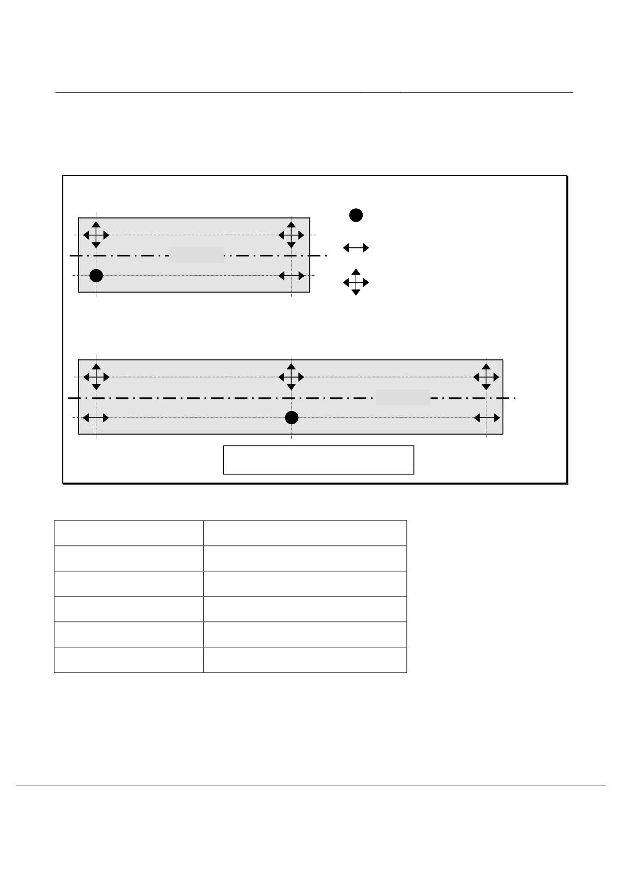
In figure 119 examples of possible support systems on single and two span beams are given.
Einfeldträger
allseits unverschiebliches Lager
längsverschiebliches Lager
X-Achse
allseits verschiebliches Lager
Zweifeldträger
X-Achse
(Spiegelung an X-Achse möglich)
Figure 119: Exemplary support arrangement for single and two span beam systems
Einfeldträger
Single span beam
Zweifeldträger
Twin span beam
Allseits unverschiebliches Lager
Support fixed on all sides
Längsverschiebliches Lager
Support which can be moved longitudinally
Allseits verschiebliches Lager
Support which can be moved in all directions
Spiegelung an x-Achse möglich
Mirroring to x-axis possible
Title
High-speed Maglev system design principles
Guideway Part I - Overriding requirements
Doc.no.:
57284
Version
White paper
Issue date
15.02.2007
Page 83
High-speed maglev systems
Maglev Technical Committee
Design principles
Guideway
Maglev
Design principles
Guideway
Part II
Design
The copyright for this document and all annexes remains with the writer
All rights reserved
Title
High-speed Maglev Systems - Design principles
Guideway - Part II: Design
Doc. no.:
57288
Version
White Paper Issue date
15.02.2007
Page 1
High-speed maglev systems
Maglev Technical Committee
Design principles
Guideway
Distributor
This document was cleared by the guideway Technical Committee for publication.
Title
High-speed Maglev Systems - Design principles
Guideway - Part II: Design
Doc. no.:
57288
Version
White Paper Issue date
15.02.2007
Page 2
High-speed maglev systems
Maglev Technical Committee
Design principles
Guideway
Revisions
Date of release: 15.02.2007, White paper, Guideway Technical Committee.
Title
High-speed Maglev Systems - Design principles
Guideway - Part II: Design
Doc. no.:
57288
Version
White Paper Issue date
15.02.2007
Page 3
High-speed maglev systems
Maglev Technical Committee
Design principles
Guideway
Table of contents
Distributor
2
Revisions
3
Table of contents
4
General
13
Purpose of the document and area of application
13
Design fundamentals
15
Abbreviations and definitions
15
Laws, regulations, standards and guidelines
17
Labelling and liability
17
References
18
Design situations
20
General
20
Vehicle related design situations
20
Frequent design situations
20
Infrequent and accidental design situations
20
Guideway related design situations
21
Environment related design situations
21
Surrounding area related design situations
21
Velocities and acceleration
22
Value limits of the travelling speeds
22
Acceleration value limits
23
Actions on the guideway
24
Arrangement of the actions
24
Permanent actions
24
Variable actions
25
Accidental actions
26
Combination of the actions
27
Power transferring interfaces vehicle - guideway
28
General
28
Designation and numbering of the partial magnets
30
Interface support magnet - long stator
30
Functions
30
Geometry
31
Interface guidance magnet - lateral guidance rails
32
Title
High-speed Maglev Systems - Design principles
Guideway - Part II: Design
Doc. no.:
57288
Version
White Paper Issue date
15.02.2007
Page 4
High-speed maglev systems
Maglev Technical Committee
Design principles
Guideway
Functions
32
Geometry
32
Interface braking magnet - lateral guidance rails
34
Functions
34
Geometry
34
Interface support skid - sliding strip
36
Functions
36
Geometry
36
Other interfaces
37
Dynamic step up of requirements
38
General
38
Influence quantities on the dynamic step up
38
General
38
Influence quantities of the guideway
38
Influence quantities of the vehicle
38
Influential excitation mechanisms
38
Excitation mechanism I
38
Excitation mechanism II
39
Excitation mechanism III
39
Excitation mechanism IV
39
Excitation mechanism V
39
Excitation mechanism VI
40
Damping characteristics
40
Establishment of the dynamic requirements
40
General
40
Dynamic step ups as a consequence of magnet regulation
41
Time variability of the magnet forces
41
Excitation of characteristic forms through the magnet regulation
42
Dynamic step ups as a consequence of mobile operation
42
Mathematical establishment of the dynamic requirements
42
Establishment of the dynamic requirements with the help of vibration coefficients
43
General
43
Mathematically established vibration coefficients
43
Test technical proven vibration coefficients
44
Limitation of the dynamic step ups
44
Characteristic values of the actions
45
Permanent actions
45
Title
High-speed Maglev Systems - Design principles
Guideway - Part II: Design
Doc. no.:
57288
Version
White Paper Issue date
15.02.2007
Page 5
High-speed maglev systems
Maglev Technical Committee
Design principles
Guideway
Self-weight(G1)
45
Planned pre-tension/force (G2)
45
Creeping and shrinkage of the concrete (G3)
45
Constant water compressive forces (G4)
45
Probable ground movements (G5)
46
Guideway superstructure
46
Guideway substructure
46
Earth pressure (G6)
46
Variable actions
47
Variable actions as a consequence of the vehicle
47
Coordinate system of the actions
47
Vehicle weight (self-weight and payload) (Q1, Q2)
49
Centre of gravity of the vehicle
50
Position of the vehicle centre of gravity in x-direction (Q3)
50
Position of the vehicle centre of gravity in y-direction (Q4)
50
Position of the vehicle centre of gravity in z-direction
50
Frequent variable actions (Q1...Q10)
51
General
51
Actions as a consequence of braking and accelerating (Q1/Q2)
52
Actions in y-direction
54
General
54
Guidance magnet initial loading
54
Free lateral acceleration (Q1, Q2)
55
Lateral forces from the guidance dynamics (Q5)
56
Reactive forces with small horizontal radii RH (Q6)
56
Guidance magnet forces from one sided propulsion
57
Actions in z-direction (Q1.. Q3)
60
Acceleration in z-direction
60
Acceleration and braking
61
Special operating situations
62
Regulated setting down of the vehicle at v = 0 km/h (Q1, Q2)
62
Set down vehicle (Q1, Q2)
62
Levitating vehicle and hovering (Q1, Q2)
62
Aerodynamic actions from the vehicle (Q7, Q8)
63
Meeting of trains (Q7a)
63
Tunnel travel (Q7b)
63
Actions on structures close to track/tunnels (Q7c)
63
Impulse (Q8a)
64
Title
High-speed Maglev Systems - Design principles
Guideway - Part II: Design
Doc. no.:
57288
Version
White Paper Issue date
15.02.2007
Page 6
High-speed maglev systems
Maglev Technical Committee
Design principles
Guideway
Direct pressure/suction action on the guideway (Q8b)
64
Wind on the vehicle (Q9)
65
General
65
Action as a consequence of side wind on the vehicle (Q9a)
66
Aerodynamic impulse as a consequence of wind (Q9b)
67
Wind with unfavourable aerodynamic influences
70
Thermal action as a consequence of propulsion (Q10)
70
Infrequent variable actions (Q11a...Q11k)
71
General
71
Exceeding of payload (Q11a)
71
Failure of a support magnet circuit (Q11b)
71
Failure of neighbouring support magnet circuits (Q11c)
72
Failure of a guidance magnet circuit (Q11d)
73
Failure of neighbouring support magnet circuits (Q11e)
73
Use of the vehicle "safe brake" (Q11f)
74
Rule
74
Special cases
75
Velocity deviations (Q11g)
77
Propulsion system failure (Q11h)
78
One-sided propulsion system failure
78
Other propulsion system malfunctions
78
One-sided set-down of the vehicle (Q11i)
78
General
78
Design situation 1
79
Design situation 2
79
Activating/contact with magnets (Q11j)
79
Support magnets
79
Guidance magnets
79
Raising frozen support skids (Q11k)
80
Increase in vehicle weight due to snow (Q11l)
80
Actions resulting from maintenance (Q30)
80
Environmental temperature (Q50)
81
General
81
Thermal fluctuations in the guideway superstructure (Q50a)
81
Linear temperature difference (Q50b)
81
General
81
Guideway superstructure
82
Guideway substructures
82
Title
High-speed Maglev Systems - Design principles
Guideway - Part II: Design
Doc. no.:
57288
Version
White Paper Issue date
15.02.2007
Page 7
High-speed maglev systems
Maglev Technical Committee
Design principles
Guideway
Uneven heating of components due to environmental factors (Q50c)
82
Table 2 - thermal fluctuations and linear temperature differencesEffect of wind on the supporting structure
(Q51)
83
Effect of wind on the supporting structure (Q51)
84
Effect of both wind and traffic on the supporting structure (Q51)
84
Effect of wind without traffic on the supporting structure (Q51)
84
Snow and ice loads (Q52)
84
Variable water pressure forces (Q53)
84
Wind load in construction stages (Q54)
85
Maintenance conditions (Q55)
85
Construction stages (Q56)
85
Actions on track switching equipment (Q57)
85
Elastic bending of deflection switches (Q57a)
85
Actions resulting from the propulsion system (Q57b)
85
Displacement resistance of bearings (Q58)
85
Failure of supporting structure elements (Q59)
85
Lateral earth pressure from variable actions (Q60)
85
Accidental actions
86
General
86
Accidental actions resulting from the vehicle
86
Actions as a result of loading gauge violations (A1)
86
Safety wind load on the vehicle (A2)
86
Accidental actions resulting from maintenance (A3)
87
Safety wind load on the supporting structure (A4)
87
Possible foundation movements (A5)
87
Impact
87
General
87
Impact of track-guided vehicles (A6)
87
Road vehicle impact (A7)
88
Ice jam, thermal ice pressure, impact from watercraft (A8)
88
Earthquakes (A9)
88
Vehicle load arrangements
89
General
89
Global load arrangements
89
Inertia forces
89
Wind on the vehicle
93
Local load arrangements
96
Support magnet/long stator interface (stator pack)
96
Title
High-speed Maglev Systems - Design principles
Guideway - Part II: Design
Doc. no.:
57288
Version
White Paper Issue date
15.02.2007
Page 8
High-speed maglev systems
Maglev Technical Committee
Design principles
Guideway
Actions from frequent design situations (Q1...Q10)
96
Actions from infrequent design situations
97
Failure of a support magnet control system (Q11b)
97
Dual failure of support magnet control systems (Q11c)
97
Other infrequent design situations (Q11a, Q11d to Q11i)
97
Local component dynamic
97
Guidance magnets - lateral guidance rails interface
98
Actions from frequent design situations (Q1...Q10)
98
Actions from infrequent design situations
99
Failure of a guidance magnet control system (Q11d)
99
Dual failure of guidance magnet control systems (Q11e)
100
Local component dynamic
100
Braking magnet/lateral guidance rails interface
101
Infrequent design situations (Q11f)
101
Local component dynamic
101
Support skid/gliding strip interface
102
Actions from frequent design situations (Q1...Q10)
102
Actions from infrequent design situations
102
Dual failure of support magnet control systems (Q11c)
102
Use of the vehicle "safe brake" (Q11f)
102
One-sided set down of the vehicle (Q11i)
102
Local component dynamic
103
Other interfaces
103
Verification
104
General
104
Verification of the ultimate limit states
106
General
106
Partial safety factors of the actions
106
Combination values
109
Proof of the performance capability limit states
111
General
111
Global deformations in discretely mounted guideway superstructures
111
General
111
Deformations in the z direction
112
Effects resulting from the vehicle
112
General
112
Simple beam N = 1
112
Title
High-speed Maglev Systems - Design principles
Guideway - Part II: Design
Doc. no.:
57288
Version
White Paper Issue date
15.02.2007
Page 9
High-speed maglev systems
Maglev Technical Committee
Design principles
Guideway
Two-span beams with the same spans N = 2
114
Two-span beams with unequal spans
114
Multiple span girders N > 2
114
Temperate differential
115
Simple beam N = 1
115
Two-span beams with the same spans N = 2
115
Two-span beams with unequal spans
115
Multiple span girders N > 2
115
Deformations specific to the building material
115
Deformations in the y direction
116
Effects resulting from the vehicle
116
General
116
Simple beam N = 1
116
Two-span beams with the same spans N = 2
116
Two-span beams with unequal spans N = 2
116
Multiple span girders N > 2
116
Temperate differential
116
General
116
Simple beam N = 1
116
Two-span beams with the same spans N = 2
116
Two-span beams with unequal spans N = 2
117
Multiple span girders N > 2
117
Deformations specific to the building material
117
Wind
117
Deformations in the x direction
117
Traffic
117
Temperature
117
Creeping and shrinkage
117
Wind
117
Deformation as a result of torsion around the x axis
118
Permitted local support structure deformations
118
Permitted deformations in guideway plates
118
Dynamic deformations when stimulating inherent frequencies
118
Permitted offsets in the functional levels
119
Variable effects to be specified
119
Permitted offsets in the stator and slider levels
119
Permitted offsets in the lateral guide rail level
119
Proof of the gap in the x direction along girder joints
119
Title
High-speed Maglev Systems - Design principles
Guideway - Part II: Design
Doc. no.:
57288
Version
White Paper Issue date
15.02.2007
Page 10
High-speed maglev systems
Maglev Technical Committee
Design principles
Guideway
Variable effects to be specified
119
Control gaps
119
Elastic gap changes as a result of traffic
119
Limit values for the gap in the x direction
120
Proof of freedom from shear
120
Special gaps
120
Elastic and plastic deformation in substructures
120
General
120
Substructure deformation in the x direction
120
Substructure deformation in the y direction
121
Plastic substructure deformation
121
Elastic substructure deformation
121
Substructure deformation in the z direction
123
Plastic substructure deformation
123
Elastic substructure deformation
123
Deformation of continuous strip foundations
124
Primary supporting framework deformation
124
Deformations in the event of collisions on the guideway
125
Metal fatigue
125
General
125
Framework conditions which are specific to high-speed maglev systems
125
Point of intersection between the longitudinal stator and the levitation magnet
126
Point of intersection between the lateral guide rail and the guidance magnet
126
Annex
127
Annex II-A: Allocation of the effects at the points of intersection
128
Annex II-B: Calculated vibration coefficients
130
General
130
Area of application
131
Examples of application
132
Examples of vibration coefficient diagrams
133
General
133
Vibration coefficient diagrams for simple beams where LSt = 12.384 m
134
Vibration coefficients for 2-section vehicles
134
Vibration coefficients for 4-section vehicles
135
Vibration coefficients for 6-section vehicles
136
Vibration coefficients for 10-section vehicles
137
Vibration coefficient diagrams for simple beams where LSt = 24.768 m
138
Title
High-speed Maglev Systems - Design principles
Guideway - Part II: Design
Doc. no.:
57288
Version
White Paper Issue date
15.02.2007
Page 11
High-speed maglev systems
Maglev Technical Committee
Design principles
Guideway
Vibration coefficients for 2-section vehicles
138
Vibration coefficients for 4-section vehicles
139
Vibration coefficients for 6-section vehicles
140
Vibration coefficients for 10-section vehicles
141
Annex II-C: Limit values for routing elements
142
Annex II-D: General limit values relating to deformation
142
Annex II-E: Tables of the magnetic forces as a result of cross-winds (Q9a)
142
Annex II-F: Calculating the levitation magnet pole forces
164
Title
High-speed Maglev Systems - Design principles
Guideway - Part II: Design
Doc. no.:
57288
Version
White Paper Issue date
15.02.2007
Page 12
High-speed maglev systems
Maglev Technical Committee
Design principles
Guideway
General
Purpose of the document and area of applicati-
on
(1)
The system specific fundamentals described in this design basis for the design and verifica-
tion process of the maglev guideway (including building structures close to the lines12) are in-
dependent of the project.13
(2)
These fundamentals are to be used as dimensioning instructions in the sense of a calculating
instruction for the guideway (see also /MSB AG-FW ÜBG/).
(3)
These fundamentals have the general system requirements in /MSB AG-GESAMTSYS/ as a
basis and also the overriding requirements of the guideway /MSB AG-FW ÜBG/.
(4)
Any available potential regarding a special layout for e.g. higher transport capacity14 is not
taken into account here. For this the required structural verifications are to be provided in
each individual case in agreement with the responsible inspectorate.
(5)
The setting down of the system specific requirements for the guideway (e.g. value limits of
the deformations) is based mainly on the experiences with proven guideway structural meth-
ods so far.
(6)
For new types of construction the unlimited practicability of these standards is to be checked.
If appropriate suitable standards are to be set in agreement with the responsible inspector-
ate.
(7)
The system specific fundamentals for laying out maglev guideways include information
about:
• the documents to be used;
• the description of the actions to be taken into account;
• the characteristic and representative values of the actions;
• the geometry (actions images and weak points) of the actions;
• the fundamentals for proof of the dynamic behaviour of the guideway;
• the instructions for the verification process of the support safety, serviceability and material fatigue
with the associated standards and value limits;
(8)
The fundamentals for establishing the characteristic and representative values of the actions
are included in /MSB AG-GESAMTSYS/ as overriding.
(9)
All components and modules of the guideway, also those for which no information for layout
is given in this design basis, are to be dimensioned and proven following the generally ac-
cepted rules of engineering in agreement with the responsible inspectorate.
(10)
For the following components and modules of the maglev specific guideway equipment, pro-
ject and style specific additional requirements of their verification processes are to be set
down:
12 In so far as system specific actions are to be taken into account (e.g. aerodynamic actions).
13 Applies for applications as regional transport and long distance transport in Germany following /MSB AG-
GESAMTSYS/. Project dependent boundary conditions like local climatic (wind, temperature etc), geological
relations (earthquake, ground etc) and operational requirements are to be correspondingly set down project
specifically.
14 Increase e.g. through increasing the payload or increase of the section number (n>10).
Title
High-speed Maglev Systems - Design principles
Guideway - Part II: Design
Doc. no.:
57288
Version
White Paper Issue date
15.02.2007
Page 13
High-speed maglev systems
Maglev Technical Committee
Design principles
Guideway
• Long stator winding including securing attachment;
• Guideway equipment for recording the guideway position including securing attachment;
• Guideway equipment for external on-board energy supply including securing attachment;
Title
High-speed Maglev Systems - Design principles
Guideway - Part II: Design
Doc. no.:
57288
Version
White Paper Issue date
15.02.2007
Page 14
High-speed maglev systems
Maglev Technical Committee
Design principles
Guideway
(11) The guideway must be made in such a way following the MbBO15 or other comparable, na-
tional regulations that it satisfies the requirements of safety and order. These requirements
are met if the guideway meets the MbBO regulations or, if these do not contain the relevant
regulations, the generally recognised rules of engineering (see § 3 paragraph (1) of the
MbBO).
(12) The design is to be carried out in such a way on the basis of the following information that
the stability and serviceability is economically and environmentally assured during the re-
quired period of use. The design is to be formed in such a way that the required maintenance
cost for guaranteeing these requirements is minimised (for standards for this see /MSB AG-
FW ÜBG/).
(13) If at least the same safety is proved as when observing the generally recognised rules of
engineering, then a deviation from the generally recognised rules can be made. Verification
of at least equal safety is to be provided to the responsible inspectorate (for this see § 3
paragraph (2) of the MbBO).
(14) All deviations from the standards of this document require the agreement of the responsible
inspectorate and verification of the compatibility within the complete system and to the rele-
vant subsystems by the supplier.
(15) This design basis applies for a maglev railway in accordance with the General Maglev Sys-
tem Act /AMbG/.
Design fundamentals
(16) This document forms part of documentation for maglev trains made up of various design fun-
damentals. The document tree is presented in figure 1 /MSB AG-GESAMTSYS/.
(17) The overriding documents for the design basis for the whole system and its annexes apply
uniformly for the whole documentation:
• Maglev design principles for the complete system, doc nr: 50630,
/MSB AG-GESAMTSYS/
• Annex 1: Maglev abbreviations and definitions, doc nr: 67536,
/MSB AG-ABK&DEF/
• Annex 2: Maglev laws, regulations, standards and guidelines, doc nr: 67539,
/MSB
AG-NORM&RILI/
• Annex 3: Maglev environment, Doc.-Nr: 67285,
/MSB AG-UMWELT/
• Annex 4: Maglev rules for operation and maintenance, doc nr: 69061,
/MSB AG-BTR/
• Annex 5: Maglev noise, Doc.-Nr: 72963,
/MSB AG-SCHALL/
Abbreviations and definitions
(18) The abbreviations and definitions given in /MSB AG-ABK&DEF/ apply.
15 Applies for application in Germany.
Title
High-speed Maglev Systems - Design principles
Guideway - Part II: Design
Doc. no.:
57288
Version
White Paper Issue date
15.02.2007
Page 15
High-speed maglev systems
Maglev Technical Committee
Design principles
Guideway
Title
High-speed Maglev Systems - Design principles
Guideway - Part II: Design
Doc. no.:
57288
Version
White Paper Issue date
15.02.2007
Page 16
High-speed maglev systems
Maglev Technical Committee
Design principles
Guideway
Laws, regulations, standards and guidelines
(1)
The laws, regulations, standards and guidelines shown in /MSB AG-NORM&RILI/ must be
observed.
(2)
The normative documents shown in /MSB AG-NORM&RILI/ contain arrangements which
become a part of the Maglev design principles through reference in the design principles.
(3)
For dated normative documents in /MSB AG-NORM&RILI/, later changes or revisions of
these publications do not apply. For undated references the last edition of the normative
document referred to applies.
(4)
The status of the standards and guidelines to be taken into account in a Maglev project must
be set down bindingly in a project specific way.
•
Labelling and liability
(1)
All numerical values contained in this design basis (e.g. characteristic values of the actions
from the vehicle, dimensions etc) are based on the table of the system characteristic values
contained in /MSB AG-GESAMTSYS/ or describe typical designs. In this table the size indi-
cations are divided into system constants/system value limits and project specific variable
characteristic values.
(2)
For each application project it must be checked whether the information contained in this
document on typical designs is appropriate.
(3)
The project specific variable values to be applied are to be documented in a project specific
specification of the values to be applied in every case.
(4)
In the creation of this document the regulations in accordance with /DIN 820/ were largely
applied.
(5)
In the following chapters
• the requirements are shown in standard script and the
• explanations and examples in italics
•
Title
High-speed Maglev Systems - Design principles
Guideway - Part II: Design
Doc. no.:
57288
Version
White Paper Issue date
15.02.2007
Page 17
High-speed maglev systems
Maglev Technical Committee
Design principles
Guideway
References
(1)
Maglev design principles
/MSB AG-GESAMTSYS/
Maglev design principles, complete system
Doc.-Nr. 50630
/MSB AG-ABK&DEF/
Maglev design principles, complete system,
enclosure 1: Maglev abbreviations and definitions
Doc.-Nr. 67536
/MSB AG-NORM&RILI/
Maglev design principles, complete system,
enclosure 2: Maglev laws, regulations, standards and guidelines
Doc.-Nr. 67539
/MSB AG-FW ÜBG/
Maglev design principles, guideway
Part I: Overriding requirements
Doc.-Nr. 57284
/MSB AG-FW GEO/
Maglev design principles, guideway
Part III: Geometry
Doc.-Nr. 41727
/MSB AG-FW TRAS/
Maglev design principles, guideway
Part IV: Routeing
Doc.-Nr. 60640
/MSB AG-FW VERM/
Maglev design principles, guideway
Part V: Measurement
Doc.-Nr. 60641
/MSB AG-FW IH/
Maglev design principles, guideway
Part VI: Maintenance
Doc.-Nr. 63842
(2)
Other references
•
/R 1/ Mangerig; Zapfe: WEP Project 28
- Studie zum temperaturoptimierten Einfeld-
Fahrwegträger im Weiterentwicklungsprogramm Magnetschwebebahntechnologie - Septem-
ber 2002
(Study on the temperature optimised single span guideway beam in the further development
plan of magnetic levitating railway technology - September 2002)
Title
High-speed Maglev Systems - Design principles
Guideway - Part II: Design
Doc. no.:
57288
Version
White Paper Issue date
15.02.2007
Page 18
High-speed maglev systems
Maglev Technical Committee
Design principles
Guideway
/R 2/ Lutzenberger, S.; Lutzens J.: Grundsatzuntersuchungen zur Bestimmung des vertikalen
globalen Schwingbeiwert ϕBg,z von Transrapid Fahrwegträgern, Endbericht, Statisches System
Einfeldträger mit LSt = LSys = 24,768 m. Im Auftrag der Transrapid International GmbH, 2005.
(Examinations of principles for determining the vertical global swing coefficient ###Bg,z of
Transrapid guideway beams, final report, static system single span beam with LSt = LSys =
24,768 m. On behalf of the Transrapid International GmBH, 2005.)
/R 3/ Lutzenberger, S.; Lutzens J.: Grundsatzuntersuchungen zur Bestimmung des vertikalen
globalen Schwingbeiwert ϕBg,z von Transrapid Fahrwegträgern, Endbericht, Statisches System
Einfeldträger mit LSt = LSys = 12,384 m. Im Auftrag der Transrapid International GmbH, 2006.
(Examinations of principles for determining the vertical global swing coefficient ###Bg,z of
Transrapid guideway beams, final report, static system single span beams with LSt = LSys =
12,384 m. On behalf of the Transrapid International GmBH, 2006.)
/R 4/ Lutzenberger, S.; Lutzens J.: Weiterführende Grundsatzuntersuchungen zur Bestimmung des
vertikalen globalen Schwingbeiwert ϕBg,z von Transrapid Fahrwegträgern, Endbericht, Sta-
tisches System Einfeldträger mit LSt = LSys = 24,768 m. Im Auftrag der Transrapid International
GmbH, 2006.
(Further examinations of principles for determining the vertical global swing coefficient of ###
Bg,z
Transrapid guideway beams, final report static system single span beam with LSt = LSys =
24,768 m. On behalf of the Transrapid International GmBH, 2006.2)
Title
High-speed Maglev Systems - Design principles
Guideway - Part II: Design
Doc. no.:
57288
Version
White Paper Issue date
15.02.2007
Page 19
High-speed maglev systems
Maglev Technical Committee
Design principles
Guideway
Design situations
General
(19) Subsequently the maglev railway specific design situations for rating of the guideway which
are to be taken into account are given.
(20) Details of the combination possibilities of actions for the vehicles are given in chapter 0 and
in the chapters 0 and 0
Vehicle related design situations
Frequent design situations
(1)
The frequent design situations of the vehicle contain all vehicle related situations without losses or faults of
modules. They are subsequently summarised and are to be taken into account in the verification process.
(2)
Raising and setting down of the vehicle at vFzg = 0 km/h (including short time of hovering for a period
of around 30 s) ⇒ 0;
(3)
vehicles alongside one another in track sections provided for this purpose (stations with ⏐α⏐ ≤ 3° and
⏐s⏐ ≤ 0.5%);
(4)
maximum delay on a track and maximum acceleration on the other track at each point of the guideway
with opposite direction of travel (in this way travel operation is also covered in the same direction as
parallel operation);
(5)
Layout of the individual tracks (e.g. for double track guideways) for both directions of travel;
(6)
Vehicles with n =2… 10 sections (≈ 50 m ... 250m) are to be taken into account regardless of the pro-
ject;
(7)
The weight of the vehicles without or with payload (vehicle weight) from /MSB AG-GESAMTSYS/ (see
also chapter ⇒ 0);
(8)
Travel in a straight direction with dips or hills or curved travel with dips or hills for the operating condi-
tions “stationary operation”, “accelerate” and “delay” respectively including airstream and dynamic lat-
eral forces 16 ⇒ 0 ... 0;
(9)
Operation with stationary and gusty wind ⇒ 0;
(10) Passing by structures close to the line and other structures ⇒ (54);
(11) Travel through tunnel with “tunnel entry”, “travel in tunnel” and tunnel exit” ⇒ (50);
(12) Meeting of trains with opposite directions of travel at each point of the guideway ⇒ 0;
Infrequent and accidental design situations
(1)
The subsequent vehicle related rating situations result from losses or faults of modules and are - re-
lated to individual guideway elements- as a rule to be regarded as infrequent or accidental situations.
(2)
Worst-Case-Halt following /MSB AG-GESAMTSYS/: standing or adjacent vehicles or slow travelling
vehicles at each point of the guideway outside the stopping points provided (the speed of travel is less
than the layout speed for frequent design situations set down which is dependent on the project and
routing);
16 Also contains the crossing of non-continuous and continuous deviations (offsets and "waves").
Title
High-speed Maglev Systems - Design principles
Guideway - Part II: Design
Doc. no.:
57288
Version
White Paper Issue date
15.02.2007
Page 20
High-speed maglev systems
Maglev Technical Committee
Design principles
Guideway
(3)
Standing or adjacent vehicles outside stations in sections of track provided for this purpose (opera-
tional stopping points and defined areas of track connected with platform areas following /MSB AG-
GESAMTSYS/) with ⏐α⏐ ≤ 12° and ⏐s⏐ ≤ 0.5% (with a possibility of icing) and ⏐s⏐ ≤ 5% (without a
possibility of icing);
(4)
Setting down of the whole vehicle on the support skids at vFzg > 0 km/h ⇒ 0;
(5)
Braking with the vehicle’s own safe brake (for travelling straight and through curves, dips or hills) fol-
lowing failure of the long stator propulsion or other faults following /MSB AG-GESAMTSYS/ (in an ex-
tremely small number of cases at the same time in the same direction)
⇒ (8);
(6)
Switching off or failure of magnets ⇒ 0 ... 0;
(7)
Use of the regulation braking system (propulsion) and safe brake at the same time;
(8)
Varied propulsion (acceleration/deceleration) on both sides of a track outside areas of motor section
switching during the alternating step method⇒ 0;
(9)
“Falling out of step” of the propulsion (slip/oscillation)
⇒ covered by the dynamic forces in 0;
(10) Braking through short circuit winding of danger points (e.g. at the connection area of platforms at end
stations or before track change installations) ⇒ covered by (8);
(11) One sided setting down of the vehicle ⇒ 0;
(12) Touching/activation of magnets ⇒ 0;
Guideway related design situations
(1)
Following /MSB AG-FW ÜBG/ it is required that no unexpected guideway related failures/faults occur
through the layout and maintenance of the guideway (safe for service life; safe life) which can lead to
increased actions.
(2)
The actions/loads as a consequence of possible failures/faults on the guideway (e.g. modified load
removal for activated redundancies) are to be taken into account.
Environment related design situations
(1)
Environment related operating situations with actions as a consequence of wind (on vehicle and
guideway), temperature and earthquake are to be taken into account in line with the project specific
requirements
(2)
If higher actions occur in comparison to the value limits of actions from the environment set down in
/MSB AG-GESAMTSYS/ then these are to be correspondingly taken into account.
Surrounding area related design situations
(1)
Project specific conditions of the surroundings such as e.g. crossing lines of traffic are to be taken into
account.
Title
High-speed Maglev Systems - Design principles
Guideway - Part II: Design
Doc. no.:
57288
Version
White Paper Issue date
15.02.2007
Page 21
High-speed maglev systems
Maglev Technical Committee
Design principles
Guideway
Velocities and acceleration
Value limits of the travelling speeds
(1)
In the layout of the guideway the project specific location dependent guideway speed limit vFzg,FW,grenz
(x) and the project specific location dependent guideway highest speed vFzg,FW,höchst (x) are to be taken
into account following /MSB AG-GESAMTSYS/. The maglev train specific maximum values for this
are:
• max location dependent guideway speed limit
: max vFzg,FW,grenz (x)
≤ 530 km/h;
• max location dependent guideway highest speed
: max vFzg,FW,grenz (x)
≤ 500 km/h;
(2)
The location dependent guideway speed limit vFzg,FW,grenz (x) defines the location dependent course of
the maximum admissible speed of a marked out stretch derived from the maximum actions applied in
the rating of the guideway as a consequence of infrequent or accidental design situations.
(3)
The location dependent guideway highest speed vFzg,FW,grenz (x) defines the location dependent course
of the maximum admissible speed of a marked out stretch derived from the maximum actions applied
in the rating of the guideway of frequent situations.
(4)
The local guideway speed may be exceeded in individual cases under certain boundary conditions for
demonstration and qualification purposes (e.g. limitation of the admissible wind speed). For this a spe-
cial project specific proof is necessary and this is to be approved by the responsible inspectorate.
(5)
The local maximum speed max vFzg,häufig (x) may not exceed the guideway highest speed as a frequent
design situation under consideration of all speed tolerances and the local marking out.
(6)
The local minimum speed min vFzg,häufig (x) may not be dropped below under consideration of all speed
tolerances and the project dependent comfort requirements.
(7)
The local maximum and minimum speeds result project specifically on the basis of the actual travel
profile.
(8)
There are few situations where the local minimum speed vFzg,häufig (x) can be dropped below or the
local maximum speed max vFzg,häufig (x) can be exceeded(vFzg,selten (x) < min vFzg,häufig (x) or. vFzg,selten (x)
> max vFzg,häufig (x)).
Title
High-speed Maglev Systems - Design principles
Guideway - Part II: Design
Doc. no.:
57288
Version
White Paper Issue date
15.02.2007
Page 22
High-speed maglev systems
Maglev Technical Committee
Design principles
Guideway
Acceleration value limits
(1)
The acceleration value limits for frequent and infrequent design situations are to be taken from the
following table 91.
Direction
Designation
Value Limits
x
Acceleration and braking
- 1.5 m/s² ≤ ax ≤ + 1.5 m/s²
y
free lateral acceleration
- 1.5 m/s² ≤ ay ≤ + 1.5 m/s²
+ 9.21 m/s² ≤ az ≤ + 11.01 m/s²
z
normal acceleration (incl. g = 9.81 m/s²)
(from g - 0.6 m/s² or
g + 1.2 m/s²)
Accelerations which deviate from this are to be taken into account in the following design situations:
a) With points the maximum free lateral acceleration is to be applied with ay = 2.0 m/s² if no project
specific deviating setting occurs.
b) For a vehicle which is in α = 12° banking (vFzg = 0 km/h) there results a free lateral acceleration
of ay = -2.04 m/s² for example or ay = -2.70 m/s² at α = 16° (Q11g).
c) Increasing of the longitudinal acceleration for error functions of the propulsion (Q11h) and when
using the “safe brake” (Q11f)
Table 91 - Value limits of the accelerations in x-,y and z-direction
Title
High-speed Maglev Systems - Design principles
Guideway - Part II: Design
Doc. no.:
57288
Version
White Paper Issue date
15.02.2007
Page 23
High-speed maglev systems
Maglev Technical Committee
Design principles
Guideway
Actions on the guideway
Arrangement of the actions
(1)
The actions (F) to be taken into account are divided into permanent (G), variable (Q) and accidental
actions (A) in the following tables following /EN 1990/. The basis for the actions is /MSB AG-
GESAMTSYS/. If appropriate project specific additions are necessary and deletions are admissible.
(2)
The variable actions are divided into frequent (normally: frequency > 1/week) and infrequent (normally:
frequency < 1/year) effects.
Permanent actions
Definition:
A permanent action (G) following /EN 1990/ is an actions which is required to apply during the com-
plete service life and the change in size over time of which is negligible or in which the change up to
attaining a particular value limit always takes place in the same direction evenly.
Nr.
Permanent actions
Chapter
G1
Permanent weight of the components
0
G2
Planned pre-tension/force
(3)
G3
Creeping and shrinkage (e.g. of the concrete)
(6)
G4
Constant water compressive forces
(8)
G5
Possible ground movements
(9)
G6
Constant earth pressure
0
Table 92 - Permanent actions
Title
High-speed Maglev Systems - Design principles
Guideway - Part II: Design
Doc. no.:
57288
Version
White Paper Issue date
15.02.2007
Page 24
High-speed maglev systems
Maglev Technical Committee
Design principles
Guideway
Variable actions
Definition:
A variable action (Q) is an action following /EN 1990/ the change in size over time of which is not
negligible or in which the change does not always take place in the same direction.
Nr.
Actions
Chapter
Frequent actions
Q1
Inertia forces including dynamics from vehicle self-weight
0
Q2
Inertia forces including dynamics from payload
0
Q3
Unequal distribution of the vehicle weight in x direction
0
Q4
Unequal distribution of the vehicle weight in x direction
(19)
Q5
Travel dynamics (dynamic forces from the track)
0
Q6
Reactive forces in narrow radii
0
Q7a
Aerodynamic forces from meeting of trains
0
Q7b
Aerodynamic forces from tunnel travel
(50)
Q7c
Aerodynamic forces on building structures close to the track
(54)
Q8a
Actions from prevailing wind: Uplift
(59)
Q8b
Actions from prevailing wind: Pressure/suction
0
Q9a
Lateral forces as a consequence of wind from environment
0
Q9b
Uplift as a consequence of wind from environment
0
Q10
Temperature as a result of propulsion
0
Infrequent actions
Q11a
Increased vehicle weight
0
Q11b
Failure of a support magnet control system
0
Q11c
Dual failure of a support magnet control circuit
0
Q11d
Failure of a guidance magnet control system
0
Q11e
Dual failure of a guidance magnet control circuit
0
Q11f
Use of the vehicle “safe brake”
(8)
Q11g
Velocity deviation
0
Q11h
Propulsion system failure
0
Q11i
Actions resulting from a windings short circuit
0
Q11j
Activating/contact with magnets (Q11j)
0
Q11k
Raising of support skids, which are frozen on the sliding surface
0
Q11l
Increase in vehicle weight due to snow
0
Table 93 - Variable (frequent/infrequent) actions from the vehicle
Title
High-speed Maglev Systems - Design principles
Guideway - Part II: Design
Doc. no.:
57288
Version
White Paper Issue date
15.02.2007
Page 25
High-speed maglev systems
Maglev Technical Committee
Design principles
Guideway
Nr.
Actions
Chapter
Q30
Actions from maintenance
0
Q50a
Environmental temperature: Thermal fluctuations
0
Q50b
Environmental temperature: Linear temperature differences
0
Q50c
Environmental temperature: Uneven heating of components
0
Q51
Wind on the supporting structure
0
Q52
Snow and ice loads
0
Q53
Variable water pressure forces
0
Q54
Wind load on construction stages
Q55
Maintenance conditions
0
Q56
Construction conditions
0
Q57a
Track switching equipment: Elastical bending of switches
0
Q57b
Track switching equipment: Inertia forces from shifting
0
Q58
Displacement resistance of bearings
0
Q59
Failure of supporting structure elements
0
Q60
Lateral earth pressure from variable actions
0
Table 94 - Other variable actions
Accidental actions
Definition:
Following /EN 1990/ an accidental action (A) is an action which is usually for a short period but of
considerable significance and which can however occur with no great probability during the planned
service life of the supporting element.
Nr.
Actions
Chapter
Actions from the vehicle
A1
Actions as a result of loading gauge violations
0
A2
Safety wind on vehicle (v=0 km/h)
0
Other accidental actions
A3
Maintenance
0
A4
Safety wind on supporting element
0
A5
Possible ground movements
0
A6
Impact of track guided vehicles
0
A7
Impact of road vehicles
0
A8
Ice jam, thermal ice pressure, impact from watercraft
0
A9
Earthquake
0
Table 95 - Accidental actions
Title
High-speed Maglev Systems - Design principles
Guideway - Part II: Design
Doc. no.:
57288
Version
White Paper Issue date
15.02.2007
Page 26

High-speed maglev systems
Maglev Technical Committee
Design principles
Guideway
Combination of the actions
(1)
The whole of the design values for the verification of reliability of the supporting structure for a bound-
ary conditions with the simultaneousness of its occurrence being taken into account is referred to as a
combination of actions following /EN 1990/.
(2)
The actions are to be combined in such a way with the possibilities given in the following table 96 that
unfavourable requirements for the rating result.
(3)
The reduction and combination factors indicated in the following chapters may be applied taking into
account the fact that certain actions with sufficient probability do not occur simultaneously with their
maximum sizes.
Observations:
Actions
Actions situa-
tions 1)
For 1) incl. Following operating conditions:
constant actions G following tab 2.
with
-
- travelling vehicle (min v, max v)
- standing vehicle
Actions from the vehicle
setting down vehicle
Q1
max
min
Vehicle self weight
levitating vehicle
Q2
Payload 2)
max
min
track situations (α, s, RH, RK,W)
Q3
Unequal distribution of the vehicle self
For 2)
3)
weight in x and y direction
A proven partial payload may be used for
Q4
proof of the operating stability (see chap 0).
dynamic lateral forces from guidance
Q5
with
without
dynamics 4)
For 3)
Q6
Reactive forces in narrow radii 5)
with
-
see chap 0
Q7
aerodynamic lateral forces
6)
with
without
For 4)
as a result of guideway deformations and
Q8
Actions from prevailing wind
6)
with
without
guideway tolerances
Q10
Temperature as a result of propulsion
with
without
For 5)
Q11
Infrequent actions
with
without
dependent on the radius in the x-y-plane
Actions from the environment
For 6)
Q9
Wind action on vehicle
6)
with
without
dependent on the travelling speed
Q50
Temperature from environment
with
without
For 7)
Q51
Wind on supporting structure
with
without
see chap 0
Q52
Snow and ice loads
with
without
For 8)
see chap 0
Q53
Variable water compressive forces
with
without
Q60
Earth pressure from variable actions
with
without
other actions
Q30
Actions from maintenance 7)
with
without
Q55
Maintenance conditions
8)
with
without
Elast. deformation of the bendable
Q57a
with
without
switches
Q58
Support-shifting resistances
with
without
Q59
Failure of load support elements
with
without
Table 96 - Typical action situations for formation of the decisive combinations
Title
High-speed Maglev Systems - Design principles
Guideway - Part II: Design
Doc. no.:
57288
Version
White Paper Issue date
15.02.2007
Page 27
High-speed maglev systems
Maglev Technical Committee
Design principles
Guideway
Power transferring interfaces vehicle - guide-
way
General
(1)
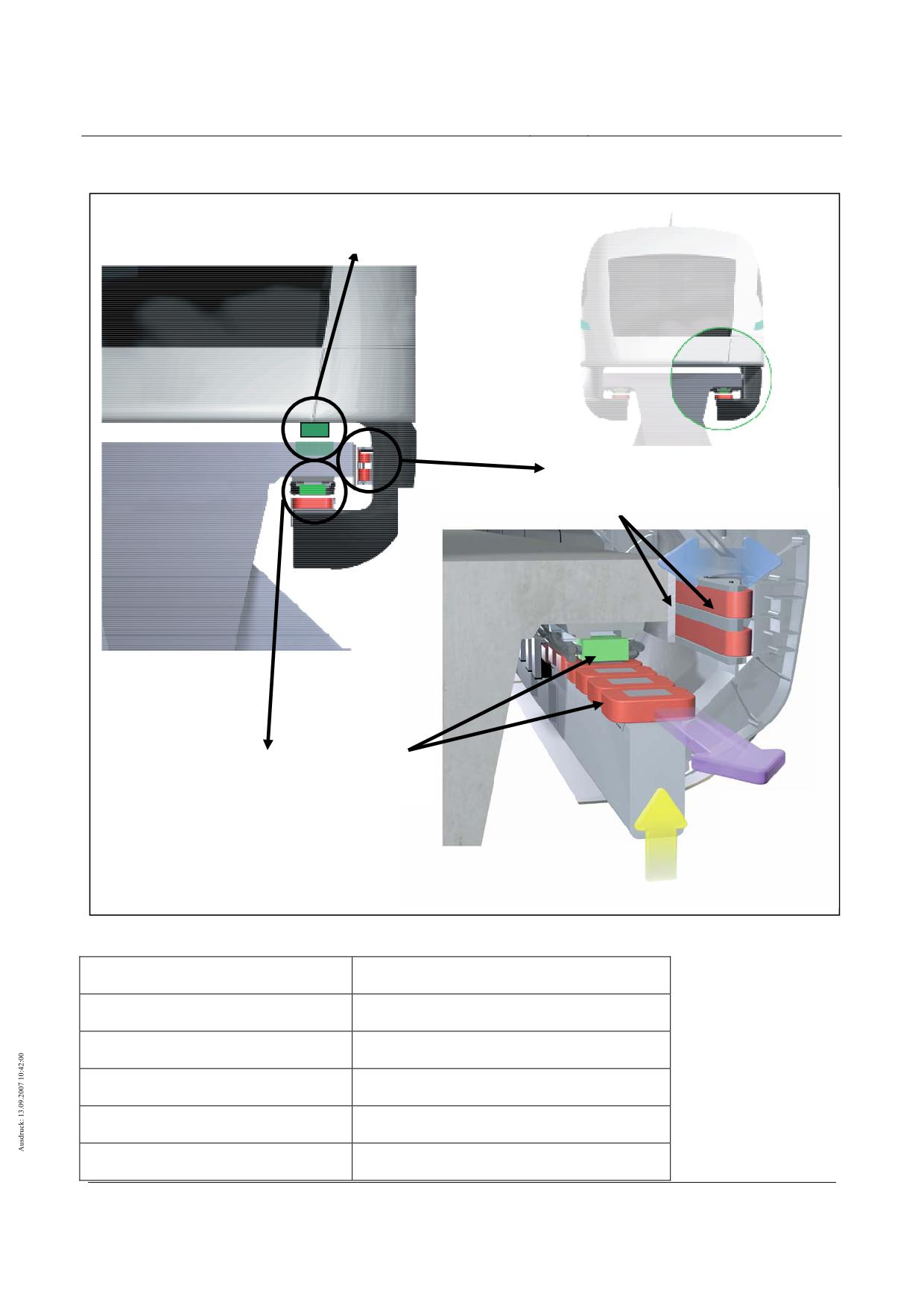
The power transferring interfaces vehicle - guideway (see figure 120)
• Support magnet - long stator,
• Guidance magnet - lateral guidance rails
• Braking magnet - lateral guidance rails and
• Support skid - sliding strip
are described in the following chapters.
(2)
The basis for this is the designs set down in /MSB AG-GESAMTSYS/. Apart from these interfaces it is
generally only aerodynamic forces (pressure/suction) which are transferred to the guideway.
(3)
In addition forces can be transferred in the area of other guideway equipment elements (e.g. external
on board energy supply) and these are to be set down for the individual case.
(4)
The inertia forces from special vehicles are usually guided to the guideway via the above interfaces.
(5)
The geometry of the guideway interface modules is set down in /MSB AG-FW ÜBG/ and /MSB AG-FW
GEO/. In addition the system specific measurements and dimensions which describe the power trans-
ferring interfaces between vehicle and guideway are given for typical designs.
(6)
Further information on the interfaces is compiled in chapter 0with the description of the load figures.
(7)
In the Annex of chapter 0the vehicle actions on the guideway are assigned to the individual interfaces
in Error! Reference source not found.
(8)
The support magnet lengths are to be used as reference sizes for the establishment of the require-
ments:
• End sections: LES = LTM-B, ES = 23,753 m
• Middle sections: LMS = LTM-B, MS = 24,768 m
Title
High-speed Maglev Systems - Design principles
Guideway - Part II: Design
Doc. no.:
57288
Version
White Paper Issue date
15.02.2007
Page 28
High-speed maglev systems
Maglev Technical Committee
Design principles
Guideway
mechanisches Tragen
Gleitleiste - Tragkufe
Führen/Bremsen
Seitenführschiene - Führ- /Bremsmagnet
Tragen/Beschleunigung/Bremsen
Langstator - Tragmagnet
Figure 120 - Interfaces vehicle-guideway
Mechanisches Tragen
Mechanical support
Gleitleiste-Tragkufe
Sliding strip - support skid
Führen/Bremsen
Guidance/braking
Seitenführschiene - Führ -/Bremsmagnet
Lateral guidance rail - guidance/braking magnet
Tragen/Beschleunigung/Bremsen
Support/acceleration/braking
Langstator -Tragmagnet
Long stator - support magnet
Title
High-speed Maglev Systems - Design principles
Guideway - Part II: Design
Doc. no.:
57288
Version
White Paper Issue date
15.02.2007
Page 29
High-speed maglev systems
Maglev Technical Committee
Design principles
Guideway
Designation and numbering of the partial magnets
(1)
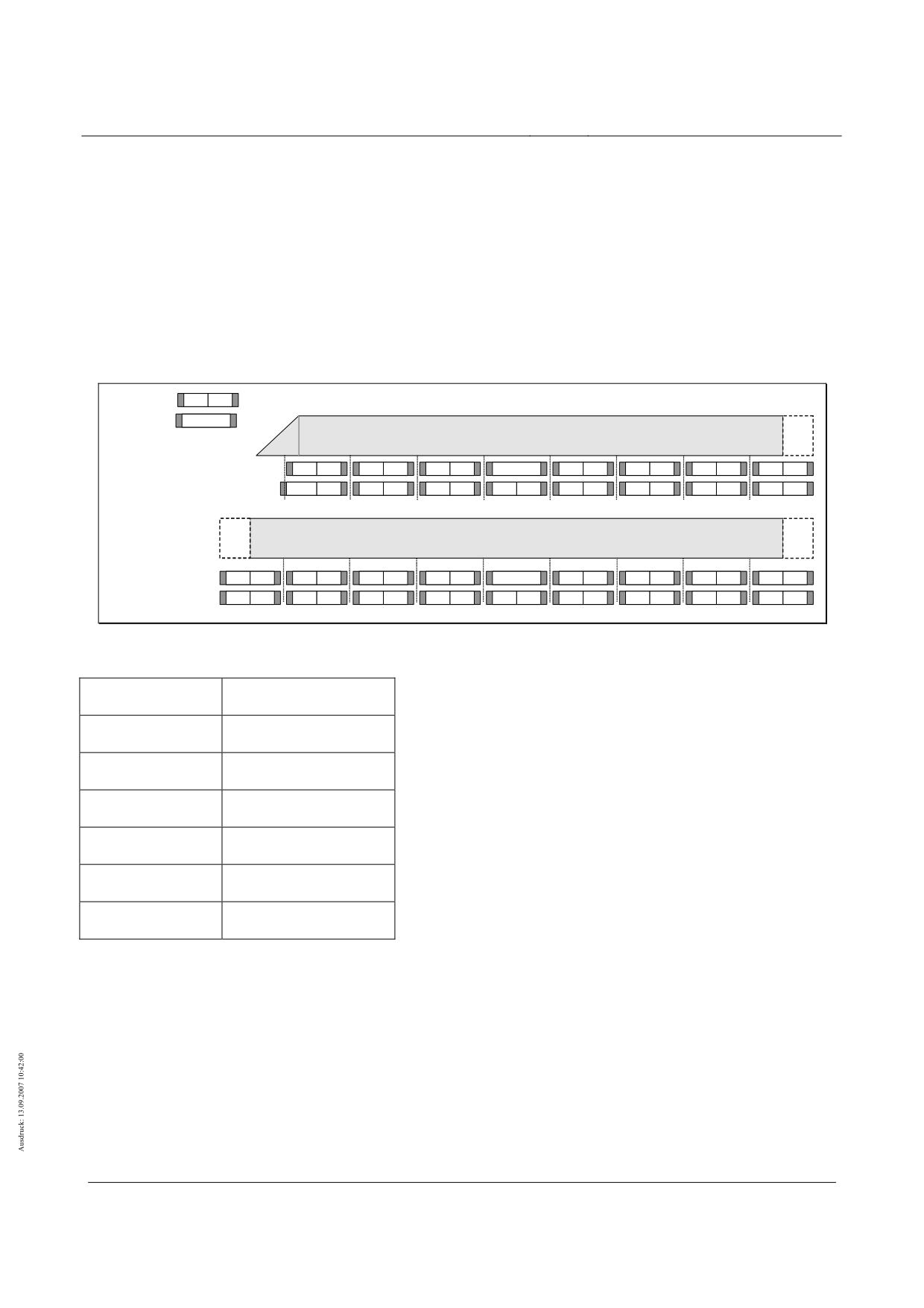
The designation and numbering of the partial magnets for supporting TMT and guiding FMT is to be
taken from figure 121 for the end and middle sections.
(2)
In this the left (le) and right (ri) vehicle/guideway side must be distinguished between.
(3)
The current state of technology for vehicles means that the partial magnets FMT 1 for guiding and
FMT 16 are not present because no section crossing guidance magnets are available.
(4)
The partial magnets for support TMT(1) and TMT(16) of the end sections correspond to the lengthen-
ing of the nose or tail magnets.
Ma
gnet
i
i+1
Bremsmagnet
BM
(Bug/
(MS/
Heck)
Endsektionen ES
ES)
Teilmagnete Führen FMTi
2
3
4
5
6
7
BM
10
11
12
13
14
15
16
(1)
Teilmagnete Tragen TMTi
(1)+2
3
4
5
6
7
8
9
10
11
12
13
14
15
16
(1)
(ES/
(MS/
Mittelsektionen MS
MS)
ES)
Teilmagnete Führen FMTi
(16)
1
2
3
4
5
6
7
BM
10
11
12
13
14
15
16
(1)
Teilmagnete Tragen TMTi
(16)
1
2
3
4
5
6
7
8
9
10
11
12
13
14
15
16
(1)
Figure 121 - Designation of the partial magnets (supporting and guidance)
Magnet
Magnet
Bremsmagnet
Braking magnet
Bug/Heck
Nose/tail
Endsektionen
End sections
Mittelsektionen
Middle sections
Teilmagnete Führen
Partial magnets guidance
Teilmagnete Tragen
Partial magnets support
Interface support magnet - long stator
Functions
(1)
-Only electromagnetic forces in the +z-direction and electromagnetic longitudinal forces in the ± x
direction resulting from propulsion and braking are transferred via the support magnet-long stator in-
terfaces (see figure 120) arranged on both sides of the guideway and vehicle.
(2)
If a partial magnet fails the neighbouring magnet takes over the forces of the failed magnet as a rule
(Q11b). If a neighbouring partial magnet fails the assigned support skid takes over the forces of the
failed partial magnets (Q11c).
Title
High-speed Maglev Systems - Design principles
Guideway - Part II: Design
Doc. no.:
57288
Version
White Paper Issue date
15.02.2007
Page 30
High-speed maglev systems
Maglev Technical Committee
Design principles
Guideway
Geometry
(1)
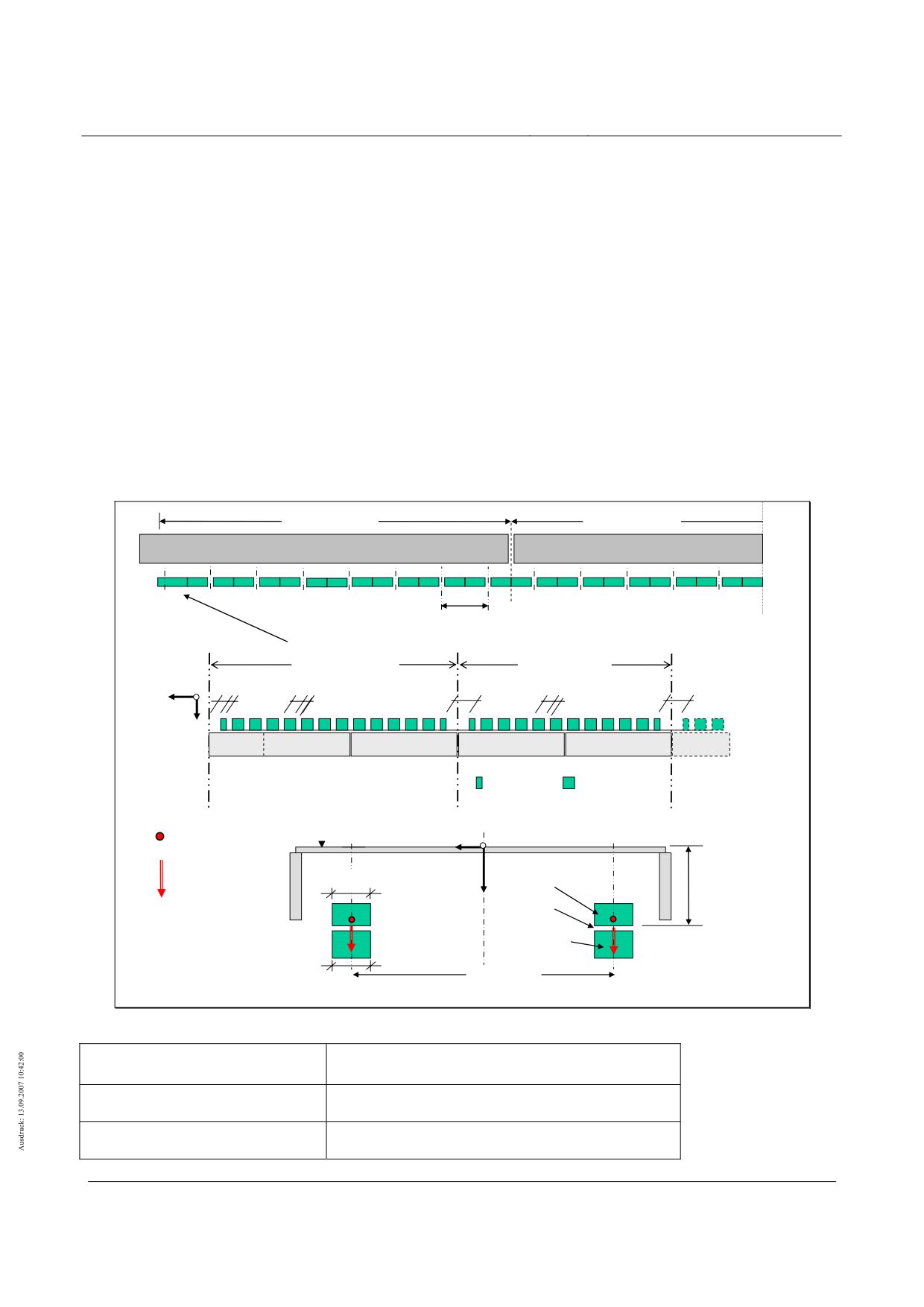
The geometry of the support magnets and the power transferring components of the support magnets
(pole bodies) is presented in figure 122.
(2)
In the sense of this design basis the length of the vehicle corresponds to the length covered by the
support magnet LTM-B. The length of a section covered by the support magnet LTM-B results from the
sum of the system lengths of the available support magnets Lsys,TM. The length covered by the support
magnets LTM-B for vehicles with n-sections (n≥ 2) with the length covered by the support magnets for
end and middle sections taken into account amounts to: LTM-B = 2 ⋅ LTM-B,ES + (n-2) · LTM-B,MS
(3)
The regulating support magnets have 10 main and 2 end poles (exception: typical design of the nose
and tail magnets with 2 additional main poles).
(4)
The system length of the regulation support magnets amounts to 3096mm (exception: typical design
of the nose/tail support magnets: Lsys,TM = 3629 mm).
(5)
The smallest system unit with reference to support magnet force amounts to: Lsys,TMT = 1548 mm =
Lsys,TM / 2
(exception: typical design on nose/tail: Lsys,TMT,nose/tail = 2081 mm).
(6)
The dimensions given are to be applied for all ranges and radii of the guideway track.
LTM-B,ES = 23753
LTM-B,MS = 24768
Endsektion
Mittelsektionen
TMTi
mit i
=
1
2
3
4
5
6
7
8
9
10
11
12
13
14
15
16
1
2
3
4
5
6
7
8
9
10
11 ...16 …1
3096
Bug- / Heck-Tragmagnet
Regel-Tragmagnet
Lsys,TM,Bug = 3629
Lsys,TM = 3096
y
88 80
166 100
176
166 100
176
x
z
1
2
3
4
5
6
7
8
9
10
11
12
1
2
3
4
5
6
7
8
9
10
1
2
(TMT1)
TMT2
TMT3
TMT4
TMT5
TMTi
Endpol
Hauptpol
OK Fahrweg (Gleitebene)
px Beschleunigung/
y
x
Fahrspurmittenachse
Bremsen
pz
Tragen
185
Langstator
Zangenmaß
z
398
Tragspalt
Seitenführ-
Tragmagnet-
Schiene
pol
Alle Maße sind Nennmaße
ey,TM = 2220
in [mm]
170
Figure 122 - Typical geometry of the actions support magnet - long stator
Endsektion
End section
Mittelsektionen
Middle sections
Bug -/Heck-Tragmagnet
Nose -/tail-support magnet
Title
High-speed Maglev Systems - Design principles
Guideway - Part II: Design
Doc. no.:
57288
Version
White Paper Issue date
15.02.2007
Page 31
High-speed maglev systems
Maglev Technical Committee
Design principles
Guideway
Regel-Tragmagnet
Regulation-support magnet
Beschleunigung/Bremsen
Acceleration/braking
Tragen
Support
Fahrweg
Guideway
Gleitebene
Sliding surface
Fahrspurmittenachse
Track central axis
Seitenführschiene
Lateral guidance rail
Langstator
Long stator
Tragspalt
Support gap
Tragmagnet -pol
Support magnet -pole
Zangenmass
Grip measurement
Alle Masse sind Nennmasse in (mm)
All measurements are nominal measurements in (mm)
Interface guidance magnet - lateral guidance rails
Functions
(1) Electromagnetic tractive forces in y direction are transferred from the actions in y-direction via the guid-
ance magnet-lateral guidance rails interface arranged on the both guideway and vehicle (see figure
123).
(2) In infrequent situations (e.g. failed magnetic regulating circuits for guiding(Q11d, Q11e)or with unfa-
vourable overlapping of extreme actions) local mechanical tractive forces are exerted in y-direction and
frictional forces in +x direction.
Geometry
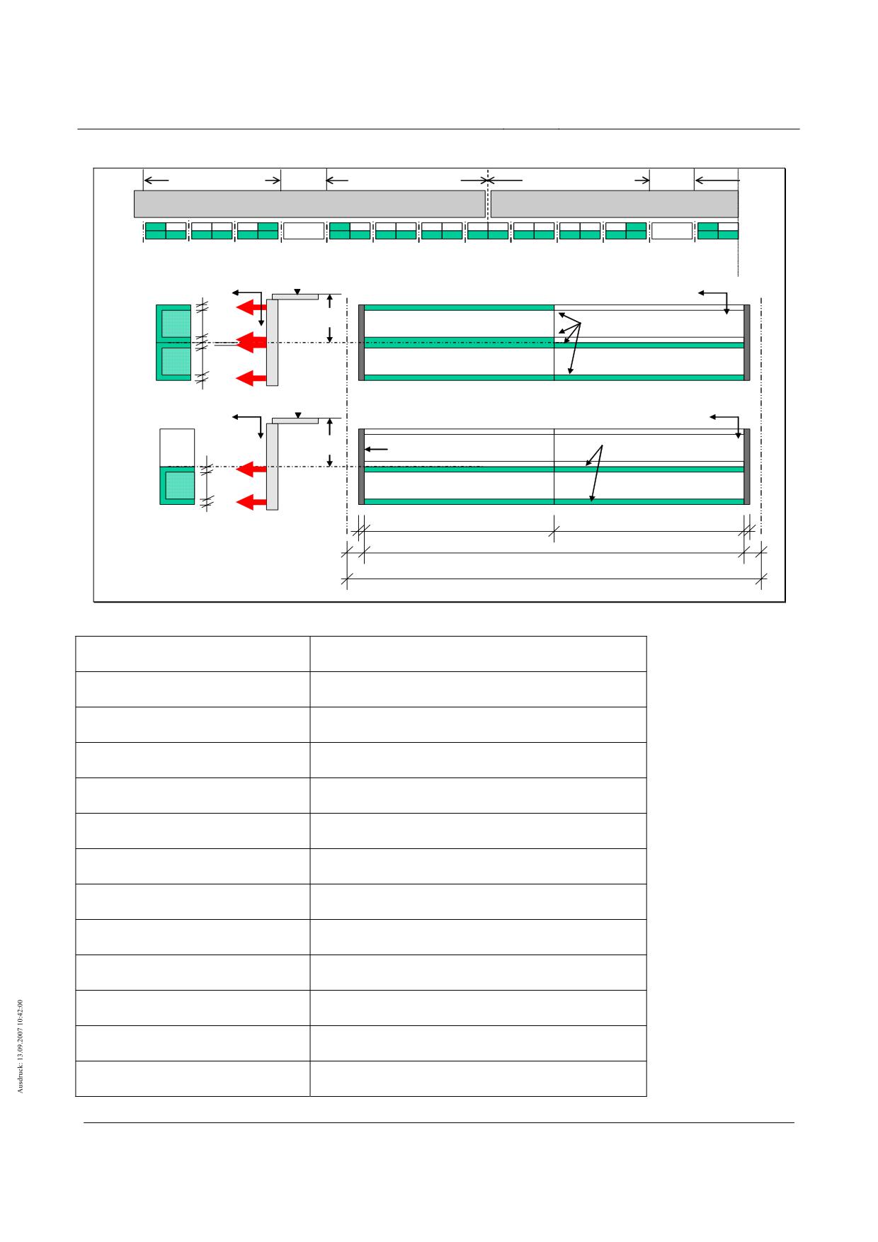
(1) The magnetic and mechanical forces are transferred via 2 or 4 longitudinal pole strips (Pl) onto the lat-
eral guidance rails (see figure 123). In the longitudinal direction gaps of 46 mm (2.23 mm) are present
every 3096m (guidance magnet system length Lsys,FM = 3,096 m). The force transferring pole-strip
length amounts to LPL,FM = 3,050 m or LPL,FMT = 1,525 m. The arrangement of the guidance magnets and
guidance magnet poles or partial magnets over the length of the vehicle is variable. A typical arrange-
ment of the individual guidance magnets is presented in figure 123.
(2) The mechanical forces for double failure of neighbouring guidance magnet circuits are transferred to the
ends of the guidance magnets via the start strips onto the guideway (bz,AL = 283 mm; bx,AL = 5 mm; see
Figure 123)
(3) For establishing the actions as a consequence of friction, typical friction coefficients between guidance
magnet and lateral guidance rails are to be taken from table 97.
(4) The lengths covered by the guidance magnets LFM-B,ES and LFM-B,MS can be derived from figure 124.
(5) The dimensions are to be applied for all ranges and radii of the guideway track.
Title
High-speed Maglev Systems - Design principles
Guideway - Part II: Design
Doc. no.:
57288
Version
White Paper Issue date
15.02.2007
Page 32
High-speed maglev systems
Maglev Technical Committee
Design principles
Guideway
3 x 3096 = 9288
3,5 x 3096 = 10836
3,5 x 3096 = 10836
Endsektion
Mittelsektionen
BM
FM_T2
FM_T1
FM_T1
FM_T1
FM_T1
BM
FM_T1
FMTi
mit i =
2
3
4
5
6
7
10
11
12
13
14
15
16
1
2
3
4
5
6
7
10
11
FM_E
FM_M
FM_E
FM_E
FM_M
FM_M
FM_M
FM_M
FM_M
FM_E
FM_E
OK Fahrweg
y
Eckmagnet FM_E
x
25
90
170
z
z
Polleisten PL
25
Mitte
Führmagnet
25
90
25
OK Fahrweg
y
Mittelmagnet FM_M
x
z
z
170
Anlaufleiste AL
Polleisten PL
25
Mitte
Führmagnet
90
25
5
5
Führmagnet
Seitenführ-
Teilmagnetlänge LPL,FMT = 1525
Teilmagnetlänge LPL,FMT = 1525
schiene
23
Polleistenlänge LPL,FM = 3050
23
Alle Maße sind Nennmaße
in [mm]
Systemlänge Lsys, FM
= 3096
Figure 123 - Typical geometry of the actions support magnet - lateral guidance rails
Endsektion
End section
Mittelsektionen
Middle sections
Eckmagnet
Corner magnet
Fahrweg
Guideway
Führmagnet
Guidance magnet
Polleisten
Pole strips
Mittelmagnet
Middle magnet
Anlaufleiste
Start up strip
Seitenführschiene
Lateral guidance rail
Alle Masse sind Nennmasse in (mm)
All measurements are nominal measurements in (mm)
Teilmagnetlänge
Partial magnet length
Polleistenlänge
Pole strip length
Systemlänge
System length
Title
High-speed Maglev Systems - Design principles
Guideway - Part II: Design
Doc. no.:
57288
Version
White Paper Issue date
15.02.2007
Page 33
High-speed maglev systems
Maglev Technical Committee
Design principles
Guideway
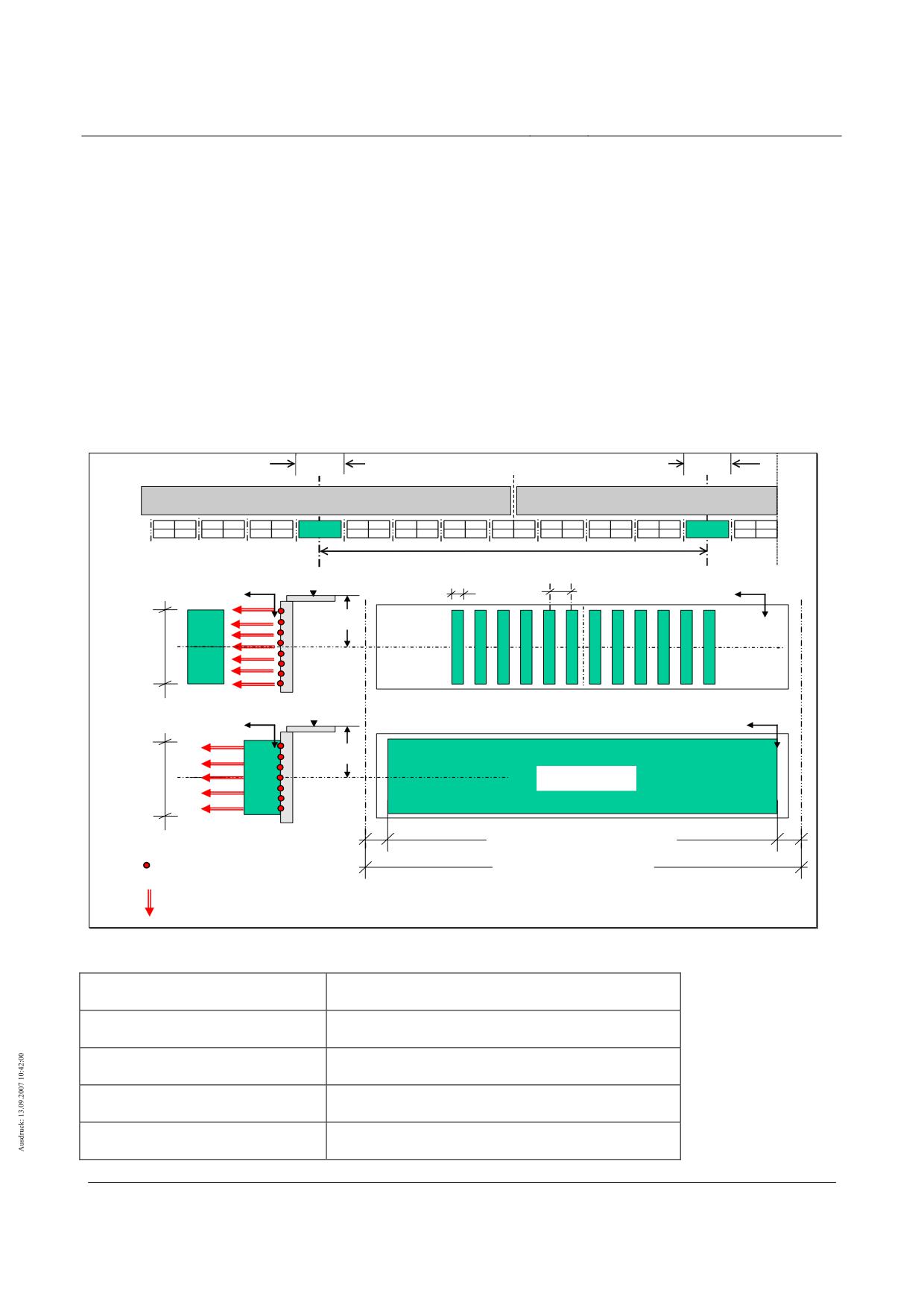
Interface braking magnet - lateral guidance rails
Functions
(1)
If the long stator motor fails electromagnetic tractive forces in y- direction and longitudinal forces in +x
direction and also mechanical frictional forces in +x direction for set braking magnets are transferred
via the interface braking magnet-lateral guidance rails (see figure 124) on both the guideway and ve-
hicle.
Geometry
(1)
A typical arrangement of the braking magnets in x-direction and the typical geometry of the load
transmitting pole bodies is given in figure 124.
(2)
The centre to centre distance of the braking magnets in x-direction amounts to ex,BM = 24,768 m.
3096
3096
Endsektion
Mittelsektionen
BM
FM_T2
FM_T1
FM_T1
FM_T1
FM_T1
BM
FM_T1
= 24 768
Mittenabstand der Bremsmagnete ex,BM
„Freier“ Brems-
OK Fahrweg
74
168
magnet
x
y
x
z
170
Mitte
288
Brems-
magnet
12 Bremspole
„Anliegender“
OK Fahrweg
y
x
x
Bremsmagnet
z
170
z
Mitte
270
Anlaufplatte
Brems-
magnet
Anlaufplattenlänge LBM,AP = 2800
Seitenführ-
schiene
px Bremsen
Systemlänge Lsys,BM = 3096
py Zugkräfte
(Wirbelstrom)
Alle Maße sind Nennmaße
in [mm]
Figure 124 - Typical geometry of the actions braking magnet - lateral guidance rails
Endsektion
End section
Mittelsektionen
Middle sections
Mittenabstand der Bremsmagnete
Middle distance of the braking magnets
Freier Bremsmagnet
Free braking magnet
Anliegender Bremsmagnet
Close braking magnet
Title
High-speed Maglev Systems - Design principles
Guideway - Part II: Design
Doc. no.:
57288
Version
White Paper Issue date
15.02.2007
Page 34

High-speed maglev systems
Maglev Technical Committee
Design principles
Guideway
Fahrweg
Guideway
Bremspole
Braking poles
Anlaufplatte
Axial buffer disk
Anlaufplattenlänge
Axial buffer disk length
Systemlänge
System length
Alle Masse sind Nennmasse in (mm)
All measurements are nominal measurements in (mm)
Seitenführschiene
Lateral guidance rails
Bremsen
Brakes
Zugkräfte (Wirbelstrom)
Tractive forces (eddy current)
(3)
The maximum friction coefficients µBM-SFS between the braking magnet and lateral guidance rails to be
applied as a function of the travel speed are to be taken from table 97.
Adhesive fric-
Dynamic friction
tion
vFzg [km/h]
0
v → 0
10
20
30
50
100
200
> 300
µBM-SFS [-]
0.50
0.30
0.25
0.22
0.20
0.18
0.14
0.12
0.10
Table 97 - Typical frictional coefficients braking magnet - lateral guidance rails (dry guideway)
Title
High-speed Maglev Systems - Design principles
Guideway - Part II: Design
Doc. no.:
57288
Version
White Paper Issue date
15.02.2007
Page 35
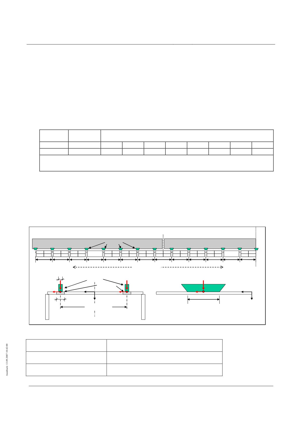
High-speed maglev systems
Maglev Technical Committee
Design principles
Guideway
Interface support skid - sliding strip
Functions
(1)
-Forces in the z and friction in the ±x and ±y direction are transferred via the support skid-sliding strips
interfaces arranged on both sides of the guideway and vehicle (see figure 125) (normally at vFzg = 0
km/h, in infrequent design situations at vFzg ≥ 0 km/h).
(2)
The process for establishing the actions to be taken into account is described in the subsequent chap-
ters.
(3)
The maximum friction coefficientsµTK-GL to be applied as a function of the travel velocity between sup-
port skid and sliding strip are to be taken from table 98 to establish the actions in x-direction as a con-
sequence of friction.
Adhesive
Dynamic friction
friction
vFzg [km/h]
0
v → 0
10
20
30
50
100
200
> 300
µTK-GL[-]
0.50 *
0.30 **
0.24
0.21
0.20
0.18
0.14
0.12
0.10
* Coefficient for taking into account the adhesive friction
** The max. friction coefficient for vFzg → 0 km/h is to be tested project specifically.
Table 98 - Typical frictional coefficients support skid - sliding strip (dry guideway)
Geometry
(1)
A typical arrangement of the support skids on the vehicle with the typical dimensions of the support
skids is presented in figure 125.
Endsektion
Mittelsektionen
Tragkufen
BM
BM
ex,TK = 3096
by,TK = 110
Tragkufen
Gleitebenen
Fx/y/z,TK
Fx/y/z,TK
OK Fahrweg
Fx/y/z,TK
x
y
z
z
150
ey,TK
= 2220
Lx,TK = 740
Alle Maße sind
Spurmittenachse
Nennmaße in [mm]
Figure 125 - Typical geometry of the actions support skid - sliding strip
Endsektion
End section
Mittelsektionen
Middle sections
Tragkufen
Support skids
Title
High-speed Maglev Systems - Design principles
Guideway - Part II: Design
Doc. no.:
57288
Version
White Paper Issue date
15.02.2007
Page 36
High-speed maglev systems
Maglev Technical Committee
Design principles
Guideway
Gleitebenen
Sliding strips
Fahrweg
Guideway
Spurmittenachse
Track central axis
Alle Masse sind Nennmasse in (mm)
All measurements are nominal measurements in (mm)
Other interfaces
(1) The interfaces to the components of the external on board energy supply and to the components for
recording the vehicle position (location) are described in /MSB AG-FW ÜBG/.
(2) The characteristic values of the actions are to be set down specifically for the project and the design.
Title
High-speed Maglev Systems - Design principles
Guideway - Part II: Design
Doc. no.:
57288
Version
White Paper Issue date
15.02.2007
Page 37
High-speed maglev systems
Maglev Technical Committee
Design principles
Guideway
Dynamic step up of requirements
General
(1) As a consequence of the transient actions on the guideway, oscillations/vibrations occur as a rule which
lead to a rise in the static guideway requirements (dynamic step up) such as to radiation of sound and
solid base noise (vibrations).
Influence quantities on the dynamic step up
General
(1) The parameters and characteristic values described subsequently influence the dynamic behaviour and
the dynamic reaction of the guideway when a vehicle travels over and thus the size of the dynamic step
ups.
Influence quantities of the guideway
(1) Characteristic frequencies and forms of the guideway structure
The dynamic behaviour of the guideway and its ability to be stimulated is determined decisively by the
associated characteristic frequencies and forms along the function planes and by the load arrangement.
Global and local characteristic frequencies and forms depend on the mass, torsional rigidity, the static
systems and the support conditions of the designs.
(2) Damping characteristics of the guideway structure
The guideway characteristics of the guideway significantly influence the size of the dynamic step ups
with harmonic stimulation above all. The damping characteristics are dependent on the materials used
and the design characteristics of the structure. The most accurate possible of the respective damping
characteristics of the guideway is required for a mathematical establishment of the dynamic require-
ments.
(3) Accuracy of position of the function planes
The greater the geometrical deviations from the ideal guideway position (e.g. positional inaccuracies of
the long stator, offset at end of beam) are, the greater the dynamic step ups of the requirements ex-
pected (for admissible deviations in position see /MSB AG-FW GEO).
Influence quantities of the vehicle
(1) Load image of the vehicle and geometrical regularities contained in it
The load image of the vehicle is decisive for the size of the dynamic step up for intermittent load.
Possible vehicle excitation frequencies result from the geometrical regularities in the load arrangement
and in the development of the support magnets/magnetic poles as a function of the travel speed.
(2) Travel speed of the vehicle
Significantly increased oscillations of the guideway beams can occur as a function of the travel speed.
Dynamic step ups are mainly to be expected at resonant travel speeds, at high travel speeds (intermit-
tent load) and at low travel speed (slow travel/hovering).
(3) Dynamic characteristics of the vehicle
All factors which the time variability of the magnetic forces influence (e.g. gap distance) have an effect
on the dynamic step up of the guideway requirements.
Influential excitation mechanisms
(1) The influential system specific mechanisms and their influence quantities are shown subsequently.
Excitation mechanism I
Title
High-speed Maglev Systems - Design principles
Guideway - Part II: Design
Doc. no.:
57288
Version
White Paper Issue date
15.02.2007
Page 38
High-speed maglev systems
Maglev Technical Committee
Design principles
Guideway
(1) Intermittent load of the guideway through crossing of the vehicle:
For vehicle lengths, guideway geometries and travel velocities present the size of the dynamic load in-
creases with the travel speed. This effect can be relevant for high travel speeds in particular.
Excitation mechanism II
(1) Geometrical regularities of the vehicle (length of the support magnet LTM; section length of the vehicle
LES/MS) lead to a periodic excitation of the guideway, the frequency of which is dependent on the travel
velocity. Stepped up guideway oscillations can result from this. The harmonic excitation of the guideway
can also lead to vibrations in the ground.
(2) The decisive wavelengths of the action result from the geometry and arrangement of the vehicle actions
(e.g. support magnets and support magnet poles or guidance magnets and guidance magnet poles).
Typical wavelengths for the actions in z-direction are e.g. λi = Lλ/i ⋅ with i = 1; 2 … and Lλ = 3,096 m;
24,768 m; 49,536 m.
(3) With the help of equation (1) the associated speed dependent excitation frequencies can be calculated.
fAnregung = vFzg / λi [Hz]
( 1)
(4) A large number of exciter frequencies thus result for the guideway which can lead to resonant dynamic
step ups in the area of guideway natural frequencies (for this see chapter 0 (4)).
Excitation mechanism III
(1) Periodic fluctuations in the magnetic forces transferred from the vehicle to the guideway through the
tooth/slot development of the long stator.
(2) As a consequence of the low dimensions these mainly have an effect on structures with short influential
lengths and at low travel velocities and lead to a periodic exciting of the guideway, the frequency of
which depends on the travel velocity.
Excitation mechanism IV
(1) Vehicle vibrations can cause periodic fluctuations of the vehicle loads. Possible causes of an exciting of
vibration of the vehicle are subsequently described.
(2) Parameter excited oscillation of the vehicle (exciter mechanism IV.a):
As a consequence of a regular, final length of the guideway beams, the rigidity of the guideway under
the support magnets can change periodically (e.g. support area, beam field). If an excitation frequency
resulting from the travel velocity and the support distance of the guideway beams is close to the natural
frequency of the vehicle or the guideway, this can lead to stepped up vibrations of the vehicle and thus
also the guideway.
(3) Excitations from the roughness of the track (excitation mechanism IV.b):
Deviations of the function planes from the ideal position (e.g. position inaccuracies of the stator packs
or displacements on the beam joints) lead to a dynamic exciting of the vehicle during crossing and thus
to vehicle vibrations which again have a retrospective effect on the guideway as a consequence.
Excitation mechanism V
(1) Dynamic effects from the regulation of the vehicle and thus in the coupling of the vehicle to the guide-
way can lead to strongly stepped up vibrations especially during slow travel/hovering and especially in
the area of natural frequencies of the guideway structure.
Title
High-speed Maglev Systems - Design principles
Guideway - Part II: Design
Doc. no.:
57288
Version
White Paper Issue date
15.02.2007
Page 39
High-speed maglev systems
Maglev Technical Committee
Design principles
Guideway
(2) The associated exchange forces can be limited by measurements on e.g. prototype vehicles.
Excitation mechanism VI
(1) Excitations as a result of infrequent actions such as e.g. fault of propulsion regulation of the long stator
linear motor (slip, swing), regulated setting down of the vehicle when using the safe brake or starting up
a support magnet on the stator pack.
Damping characteristics
(1) With regard to a reduction of dynamic step ups it is recommended to use designs/construction methods
with a high degree of natural damping.
(2) The damping measurements following EN 1991-2:2003 Tab. 6.6 or experimentally established damping
values may be used if these can be proved as representative for the respective case of application and
are agreed with the responsible inspectorate.
(3) If damping measurements following (2) are not available, the values given in table 99 can be used for
the dynamic tests as a conservative damping measurement D in % of the critical damping (damping
factor).
Beam/component from
Conservative damping measurement D [%]
welded steel structures
0.3
screwed steel structures
0.4 .. 0.6 (dependent on the design)
Ferro concrete
0.6
Pre-stressed concrete
0.6
Steel bonding
0.6
Ground
project specific
Table 99 - damping measurements D in % of the critical damping
Establishment of the dynamic requirements
General
(1) The general requirements for furnishing proof of dynamic actions are to be taken from
• DIN specialised report 101 chap. -6.4; Annex H;
• DIN 1055-100, chap. 5.4
• Eurocodes (e.g. EN 1990 - chap. 4.1.5; chap. 5.1.3 and EN 1991-2 - chap. 6.4)
(2) In establishing the dynamic requirements all actions from the travelling operation and if appropriate the
environment (wind, earthquake) are to be taken into account with their special characteristics.
(3) The local increase as a consequence of the magnet regulation is to be taken into account in line with
chapter 0.
(4) In the mathematical determination of dynamic requirements while using suitable calculation pro-
grammes, the information in chapter 0 is to be taken into account
(5) Dynamic actions may be accepted as quasi-permanent actions in so far as vibration coefficients are
available and agreed with the responsible inspectorate.
Title
High-speed Maglev Systems - Design principles
Guideway - Part II: Design
Doc. no.:
57288
Version
White Paper Issue date
15.02.2007
Page 40
High-speed maglev systems
Maglev Technical Committee
Design principles
Guideway
(6) For verification of the serviceability of the guideway with regard to its vibration behaviour, the require-
ments for system compatibility of vibration amplitudes contained in chapter Error! Reference source
not found. is to be taken into account.
(7) Dynamic requirements in the resonance area are to be demonstrably limited through suitable measures
(e.g. damping by oscillation/vibration dampers) in such a way that the serviceability, the support safety
and operating stability can be proven for the project specific service life required with the resonance re-
quirements being taken into account.
(8) The theoretical assumptions and calculation results are to be verified through measurement of the dy-
namic requirements following /MSB AG-FW ÜBG/.
Dynamic step ups as a consequence of magnet regulation
Time variability of the magnet forces
(1)
In order to adhere to the required air gap at the support magnet/long stator and guidance
magnet/lateral guidance rail interfaces, the magnetic forces are regulated in line with the lo-
cal and temporary gap ratios (see reliable guideway tolerances following /MSB AG-FW
GEO/.
(2)
The time variability (dynamic) of the magnetic forces (reaction forces as a consequence of
position tolerances of the long stator and the lateral guidance rails, slip, oscillation) which re-
sults from this is to be taken into account for local proofs in the interface area (support mag-
net-long stator, guidance magnet-lateral guidance rails) for respectively one partial magnet
for support or guidance (see chapter 7.3 and 9.3).
(3)
For the verification process the following step up coefficients ϕRl are to be applied:
min ϕRl,x/y/z = 0.8 and max ϕRl,x/y/z = 1.2
(4)
The higher value limits of the static actions indicated in chapter 9 are to be used as capacity
limits of the support and guidance magnets. The step ups maxϕRl,x/y/z are already included in
this.
Title
High-speed Maglev Systems - Design principles
Guideway - Part II: Design
Doc. no.:
57288
Version
White Paper Issue date
15.02.2007
Page 41
High-speed maglev systems
Maglev Technical Committee
Design principles
Guideway
Excitation of characteristic forms through the magnet regulation
(1)
During slow travel and hovering in particular characteristic forms of guideway elements can be excited
by variable magnetic forces as a consequence of the gap regulation. The requirements and deforma-
tions as a consequence of these excitations are to be proved.
(2)
The type/method of the verification process is to be agreed with the responsible inspectorate.
(3)
Possibilities for the verification process are:
• Theoretical verification process through dynamic FEM calculations e.g. through response analysis;
(the excitation forces and associated frequency areas are to be set down in agreement with the re-
sponsible inspectorate in a project specific way.)
• If no values are set down in agreement with the responsible inspectorate, excitation forces as in
harmonic varying forces in the characteristic frequencies of the beam with maximum power ampli-
tudes of ∆pz = ∆py = ± 1 kN/m can be assumed for estimation of the dynamic step ups. Here the
frequency range of 0 to 30 Hz is decisive.
• Measurement of the dynamic deformations and requirements of a prototype beam with simultane-
ous verification of the system behaviour;
• Checking of guideway elements in the test stand;
(4)
In addition to a mathematical verification, an inspection of the guideway designs through test technical
checking of the dynamic behaviour and measurement of the dynamic requirements for slow crossing
and hovering is required.
Dynamic step ups as a consequence of mobile operation
Mathematical establishment of the dynamic requirements
(1)
In the mathematical establishment of the dynamic requirements to be proven, the load arrangements
of chapter 0 are to be applied. In addition the influence quantities and excitation mechanisms de-
scribed above are to be taken into account.
(2)
The models for the guideway structures are to be chosen in such a way that geometry, rigidity, support
ratios and distributions of mass and the dynamic characteristics (natural frequency, characteristic
forms, damping) can be represented sufficiently realistically. The structures are to be portrayed via
suitable methods such as e.g. the finite elements method. The parameters of the guideway beams are
to be varied in their whole (or project specific) band width. The damping is to be estimated conserva-
tively following chapter 0. The influence of the guideway substructure and guideway foundation is also
to be recorded in the calculation of the dynamic requirements as far as this is necessary. The exami-
nation of the global reaction of the guideway beam can normally occur with models.
(3)
The depiction of the periodic excitation from the slot-tooth development of the long stator can occur
through an increased (reduced) power transfer of the magnetic forces with location equality with the
teeth (grooves) of the long stator. Here it is to be assumed that the total power transfer occurs over
the teeth of the long stator.
(4)
The actions from the vehicle must depict the characteristics of the vehicle sufficiently accurately (e.g.
geometry of the support/guidance magnets). In particular the decisive excitation mechanism must be
covered by the assumptions.
(5)
For known natural frequencies of the guideway, the travel speeds at which a resonant excitation of the
guideway construction is to be expected can be determined by equation (1).
(6)
The information contained in chapter 0 is to be taken into account for consideration of the dynamic
step ups as a consequence of the magnet regulation at low travel speeds and when hovering.
(7)
If models for other dynamic actions (e.g. wind, earthquake) are used, these must depict the size, posi-
tion, direction and course, positional and time variability, frequency of repetition and excitation fre-
quencies of the individual parts of the action sufficiently accurately.
Title
High-speed Maglev Systems - Design principles
Guideway - Part II: Design
Doc. no.:
57288
Version
White Paper Issue date
15.02.2007
Page 42
High-speed maglev systems
Maglev Technical Committee
Design principles
Guideway
(8)
For carrying out of the dynamic simulation calculation a time integration function is to be chosen which
guarantees sufficient result quality. The size of the time step is to be chosen sufficiently finely.
(9)
The simulation calculations are to be carried out up to maximum design speed for a sufficient number
of speeds (e.g. with a speed pattern of ∆vFzg = 1 m/s). The speed ranges in which the excitation fre-
quencies of the vehicle coincide with the natural frequencies of the guideway are to be given particular
examination. Here the extension of the period of the time integration process for establishing reso-
nance speed is to be taken into account.
Establishment of the dynamic requirements with the help of vibration coefficients
General
(1)
As a rule the effect of the non resting actions on the guideway can be established by quasi-permanent
verification as the actions are multiplied with vibration coefficients ϕ.
(2)
The vibration coefficients are to cover the decisive effects of the excitation as a function of the damp-
ing here.
(3)
The dynamic step ups can as a rule be established by global vibration coefficients ϕBg and local vibra-
tion coefficients ϕBl:
• The global vibration coefficients ϕBg refer to the requirements in the main support direction (x-, y-
and z- direction) of the guideway beams and are also to be taken into account in the layout of the
substructure.
• In the immediate area of the interfaces between the vehicle and guideway locally greater dynamic
step ups result as a function of the local design boundary conditions (rigidity and damping ratios)
and the load arrangements of the actions (geometry and frequency) and these are to be taken into
account through local vibration coefficients ϕBl. Local vibration coefficients are thus to be taken
into account in e.g. the cantilever arm area of discretely supported guideway beams and for short
guideway elements such as e.g. guideway plates.
(4)
The time variability of the magnetic forces is taken into account through the local vibration coefficients
given in chapter 0.
(5)
With reference to the serviceability of the guideway a maximum vibration coefficient of 1.5 is to be
aimed for as the upper limit for the dynamic step up of the requirements.
(6)
The vibration coefficients can be established mathematically or experimentally taking into account the
notes given in the subsequent sections.
Mathematically established vibration coefficients
(1)
Design dependent vibration coefficients can be derived from mathematically determined dynamic re-
quirements. These can be used for the dimensioning of the guideway elements if the assumptions
made are confirmed by the responsible inspectorate. Notes on the mathematical establishment of dy-
namic requirements (instructions and boundary conditions) are compiled in chapter 0 for this purpose.
(2)
For single span beam systems with typical support scopes, exemplary rating figures for the global
vibration coefficient ϕBg,z for actions in a vertical direction as a function of the damping in accordance
with table 1 and the vehicle length (2,4,6 and 10 sections) are given independent of design and ex-
plained with reference to their application limits. As long as there are no more precise findings, no vi-
bration coefficients smaller than ϕBg,z and ϕBg,z,WSE may be used for horizontal actions and for effective
torsion moments in accordance with Annex II-B.
(3)
As long as there are no more accurate findings or own mathematical examinations, no vibration coeffi-
cients smaller than for single span beam systems should be used for twin span beam systems with the
same support scope.
Title
High-speed Maglev Systems - Design principles
Guideway - Part II: Design
Doc. no.:
57288
Version
White Paper Issue date
15.02.2007
Page 43
High-speed maglev systems
Maglev Technical Committee
Design principles
Guideway
Test technical proven vibration coefficients
(1)
The use of test technically established and proven vibration coefficients is admissible as long as the
following boundary conditions are met:
• The design of the guideway beam to be proven is similar to guideway designs already verified (ri-
gidity, mass per unit area, support scopes, support systems).
• The operational boundary conditions of the test technical furnishing of proof (vehicle geometry and
equipment and also operating and track parameters) cover the project specific requirements.
• The travel speeds resulting from equation (1) in which a resonant excitation of the guideway de-
sign is to be expected are covered by the tests.
(2)
The current state of knowledge regarding the test technically proven vibration coefficients and the
associated boundary conditions can be requested from the responsible inspectorate.
Limitation of the dynamic step ups
(1)
The dynamic response of the guideway is to be limited by suitable measures such as e.g. by increas-
ing the damping (e.g. use of vibration dampers) in case:
• the admissible deformations following section 10.3 are exceeded,
• the required period of use cannot be attained as a consequence of dynamic step up of the re-
quirements and/or
• the behaviour of the linked system vehicle/guideway is not system compatible.
Title
High-speed Maglev Systems - Design principles
Guideway - Part II: Design
Doc. no.:
57288
Version
White Paper Issue date
15.02.2007
Page 44
High-speed maglev systems
Maglev Technical Committee
Design principles
Guideway
Characteristic values of the actions
Permanent actions
Self-weight(G1)
(1)
The self-weights of the components are to be determined following the relevant standards and regula-
tions.
(2)
For the maglev railway specific equipment components the following values are to be assumed:
• Long stator including motor winding, earth and securing attachment
: 1.4 kN/m 17)
• Lateral guidance rails, sliding strips
:
18)
• Components of the external on board energy supply including securing attachment
: 0.25 kN/m
• Supplement for other add on parts
: 0.10 kN/m
(3)
The above actions from the individual components of the maglev railway specific guideway equipment
are to be proven by measurement of weight.
Planned pre-tension/force (G2)
(4)
The pre tension for pre-stressed concrete is a permanent action. For practical reasons it may however
be treated differently (see EN 1992). Force in the sense of G2 can for example be a forced deforma-
tion of beam through its weight or pretensioning against a support.
(5)
Pre-tension can be created by pre-stressing elements, anchorings (e.g. on guideway plates), change
of the support conditions, pre-loading or other measures,
(6)
Planned pre-tension and force are to be taken into account.
Creeping and shrinkage of the concrete (G3)
(7)
Creeping and relaxation are action dependent and are thus to be assigned to the creating action com-
binations.
(8)
The actions from creeping and shrinkage may be taken into account if the requirements become more
favourable. They must be taken into account if the requirements become less favourable as a result.
Constant water compressive forces (G4)
(9)
The actions from constant hydraulic pressure are to be taken into account following the relevant regu-
lations and standards.
17 per side of the guideway beam;
18 The self-weights of the lateral guidance rails and sliding strips are to be established in accordance with the
general requirements (dimensions and materials) from /MSB AG-FW ALLG/ under consideration of the
respective design layout.
Title
High-speed Maglev Systems - Design principles
Guideway - Part II: Design
Doc. no.:
57288
Version
White Paper Issue date
15.02.2007
Page 45
High-speed maglev systems
Maglev Technical Committee
Design principles
Guideway
Probable ground movements (G5)
Guideway superstructure
(1)
The values of the probable ground movements to be applied for rating of the guideway superstructure
correspond to the value limits of the admissible deformations of the guideway substructure (see chap-
ter Error! Reference source not found.). These values are to be applied in every unfavourable posi-
tion.
(2)
In an individual case (e.g. for flow through systems with short support scopes) the probable ground
movements to be applied may however be reduced in agreement with the responsible inspectorate
and on proof of the compatibility to the vehicle. In this way it is to be guaranteed through maintenance
that the guideway is adjusted before exceeding the reduced values.
(3)
Before reaching the system value limits of the subsidence (established in the verification of service-
ability) the supports are to be adjusted. If this system value limit is applied as a possible ground
movement, γQ = 1.0 may be applied for the guideway superstructure (see also ENV 1991-3: C2.3).
Guideway substructure
(10) The guideway substructure is to be formed in such a way that the probable ground movements can be
balanced by adjustment of the supports of the guideway superstructure in each case (see also /MSB
AG-FW ÜBG/, chapter 10.2.2).
(11) The support positions following adjustment of the supports are to be taken into account in the guide-
way verification process (weak points of the support forces).
Earth pressure (G6)
(12) The earth pressure is to be established and proved following the generally recognised rules of engi-
neering.
Title
High-speed Maglev Systems - Design principles
Guideway - Part II: Design
Doc. no.:
57288
Version
White Paper Issue date
15.02.2007
Page 46
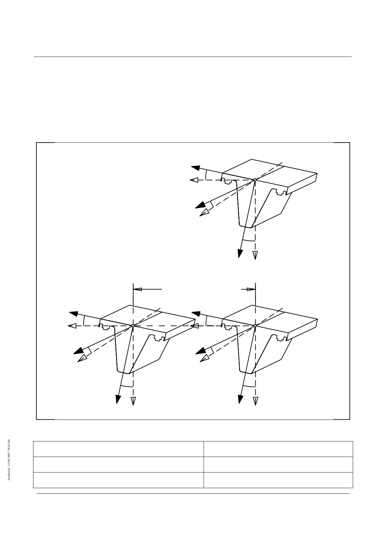
High-speed maglev systems
Maglev Technical Committee
Design principles
Guideway
Variable actions
Variable actions as a consequence of the vehicle
Coordinate system of the actions
(21) The following actions refer to the Cartesian coordinates system presented in figure 126.
(22) For this see also/MSB AG-FW TRAS/, /MSB AG-FW VERM/.
α
Fahrwegquerneigung
y
β
Fahrweglängsneigung
"0"
α
"0"
Ursprung, liegt auf der Raumkurve
Y
X,Y
,Z globale Fahrwegkoordinaten
X- u. Y-Achse waagrecht
Z-Achse lotrecht
β
x, y
, z lokale Fahrwegkoordinaten
x
x-Achse mit β mitdrehend
X
y- u. z-Achse mit α mitdrehend
α
Einzelspurfahrweg
1..n
Nummerierung der Spuren
bei mehreren Fahrspuren n>1
(siehe Beispiel Doppelspurfahrweg)
z
Z
Spurmittenabstand
S
y1
y2
α1
"01"
α2
"02"
Y
Y2
x1
β1
x2
β2
X1
X2
α1
α2
Doppelspurfahrweg
z1
z2
Z1
Z2
Figure 126 - Coordinate system of the actions
Fahrwegquerneigung
Guideway transverse inclination
Fahrweglängsneigung
Guideway lengthways inclination
Ursprung, liegt auf der Raumkurve
Origin, lies on the space curve
Title
High-speed Maglev Systems - Design principles
Guideway - Part II: Design
Doc. no.:
57288
Version
White Paper Issue date
15.02.2007
Page 47
High-speed maglev systems
Maglev Technical Committee
Design principles
Guideway
Globale Fahrwegkoordinaten X- u. Y-Achse waagrecht Z-
Global guideway coordinates X and Y axis horizontal
Achse lotrecht
Z-axis perpendicular
Lokale Fahrwegkoordinaten x-Achse mit β mitdrehend y-u.z
Local guideway coordinates -axis with β rotating in
Achse mit α mitdrehend
same direction
Nummerierung der Spuren bei meheren Fahrspuren n>1 (siehe
Numbering of the tracks for several tracks n>1 (see
Beispiel Doppelspurfahrweg)
example double track guideway)
Einzelspurfahrweg
Single track guideway
Spurmittenabstand
Track centre distance
Doppelspurfahrweg
Double track guideway
Title
High-speed Maglev Systems - Design principles
Guideway - Part II: Design
Doc. no.:
57288
Version
White Paper Issue date
15.02.2007
Page 48
High-speed maglev systems
Maglev Technical Committee
Design principles
Guideway
Vehicle weight (self-weight and payload) (Q1, Q2)
(13) As a static action as a consequence of vehicle weight (vehicle self-weight and payload) the inertia
forces pZ following table 100 are to be applied for the dimensioning of the guideway following /MSB
AG-GESAMTSYS/.
(14) The track loads provided for the vehicle weight are averaged across the support magnet occupation
length LTM-B (see figure 122). For the design of the guideway the local actions about the vehicle length
are to be determined from these average track loads while applying the equations and tables indicated
in the subsequent chapters.
(15)
(16) A possible unequal distribution of the payloads in x- and y- direction (Q3, Q4) is to be taken into ac-
count in accordance with the chapters 0 and 0.
(17) The use of the average track loads or own simplifications of the subsequent load arrangements is
admissible if it is proved that the requirements established through the simplification are on the safe
side.
Averaged, static track load
Designation
Frequency *
[kN/m]
Vehicle self weight EG (minimum vehicle weight)
p Z, EG = 21,0
**
-
medium vehicle weight MG (for normal load)
pZ, MG = 26,0
***
80 %
admissible vehicle weight ZG (for maximum load)
pZ, ZG = 29,0
***
20 %
maximum vehicle weight HG (e.g. in the case of fire,
pZ, HG = 31,0
-
evacuation of a section) ****
Observations:
*
The frequencies indicated are to be tested for each product and adapted if appropriate.
**
For the use of lighter vehicles a reduced track load for the vehicle self weight can be set down project spe-
cifically (e.g. light goods vehicle with pZ,EG = 19,0 kN/m).
***
For proof of fatigue a vehicle weight MG* = p can be applied more simply in place of the actions from the
middle vehicle weight MG (80%) and the admissible vehicle weight ZG (205)
****
The classification of the maximum vehicle weight HG is to be set down project specifically as frequent,
infrequent or unusual action. As a rule the maximum vehicle weight is to be assumed as an unusual action.
Table 100 - Typical mean, static actions from the vehicle weight
Title
High-speed Maglev Systems - Design principles
Guideway - Part II: Design
Doc. no.:
57288
Version
White Paper Issue date
15.02.2007
Page 49
High-speed maglev systems
Maglev Technical Committee
Design principles
Guideway
Centre of gravity of the vehicle
Position of the vehicle centre of gravity in x-direction (Q3)
(18) The centre of gravity of the vehicle weight can shift through uneven distribution of the payload and the
vehicle self weight in x-direction (Q3). This uneven distribution is passed on over the vehicle structure
(e.g. distribution of the loads over air spring systems) to the support and guidance magnets and is
taken into account in the subsequent tables of actions (e.g. table 105).
(19) With vehicles for goods transport it is to be assured through a project specific loading instruction that
an uneven loading in x-direction does not lead to load distributions more unfavourable than those indi-
cated in table 105.
Position of the vehicle centre of gravity in y-direction (Q4)
(20) The centre of gravity of the vehicle weight can be shifted in the y-direction (Q4) through uneven distri-
bution of the payload. This shifting of the centre of gravity is negligible when including the track loads
in Table 100.
(21) With vehicles for goods transport it is to be assured through a project specific loading instruction by
the operator that there is no uneven loading in y-direction.
Position of the vehicle centre of gravity in z-direction
(1)
The highest position of the vehicle centre of gravity above the level of the sliding strips
amounts to:
• minimum vehicle weight sz,EG =
- 600 mm;
• medium vehicle weight sz,MG
=
- 700 mm;
• admissible vehicle weight sz,ZG
=
- 850 mm;
• maximum vehicle weight sz,HG =
- 950 mm;
These centre of gravity positions are to be taken account of with the inertia forces in x- and y- di-
rection.
Title
High-speed Maglev Systems - Design principles
Guideway - Part II: Design
Doc. no.:
57288
Version
White Paper Issue date
15.02.2007
Page 50
High-speed maglev systems
Maglev Technical Committee
Design principles
Guideway
Frequent variable actions (Q1...Q10)
General
(2)
The connection between the track parameters, the speed of travel and the acceleration is
defined through the following relations:
• acceleration ax (x) in x-direction from starting up and braking
|ax (x)| ≤ 1,5 m/s²ax (x)| ≤ 1,5 m/s²
( 2)
• Free lateral acceleration ay (x) in y-direction
2
2
v(x)
⎛
v(x)
⎞
2
⎜
⎟
( 3)
a
y
(x)
=
⋅cosα(x)⋅cos
β(x)
−
g⋅cosβ(x)
+
⋅
sinα(x)
⎜
⎟
R (x)
-
R
(x)
H
⎝
V,K/W
⎠
• Normal acceleration az (x) in z-direction
2
2
v(x)
⎛
v(x)
⎞
2
a
(x)
=
⋅sinα(x)⋅cos
β(x)
+
⎜g⋅cosβ(x)
+
⎟
⋅cosα(x)
z
⎜
⎟
H
R (x)
-
R
V,K/W
(x)
( 4)
⎝
⎠
with:
ax(x),
[m/s²]
in direction of the local coordinate axes, location dependent accelera-
ay(x),
tions;
az(x)
v(x)
[m/s]
Location dependent speed of travel;
RH (x)
[m]
Location dependent horizontal radius of the space curve in the ground
plan;
RV (x)
[m]
Location dependent vertical radius of the space curve in the gradient
with
RV,K : Peak (+) and RV,W : Depression (-);
α(x)
[°]
Location dependent angle of rotation of the guideway round the x-axis
(guideway banking);
β(x)
[°]
Location dependent angle of rotation of the guideway round the y-axis
(guideway longitudinal gradient);
(3)
The connection between actions F, acceleration a and vehicle mass m is given by Newton’s
law:
F = m ⋅ a
( 5)
Title
High-speed Maglev Systems - Design principles
Guideway - Part II: Design
Doc. no.:
57288
Version
White Paper Issue date
15.02.2007
Page 51
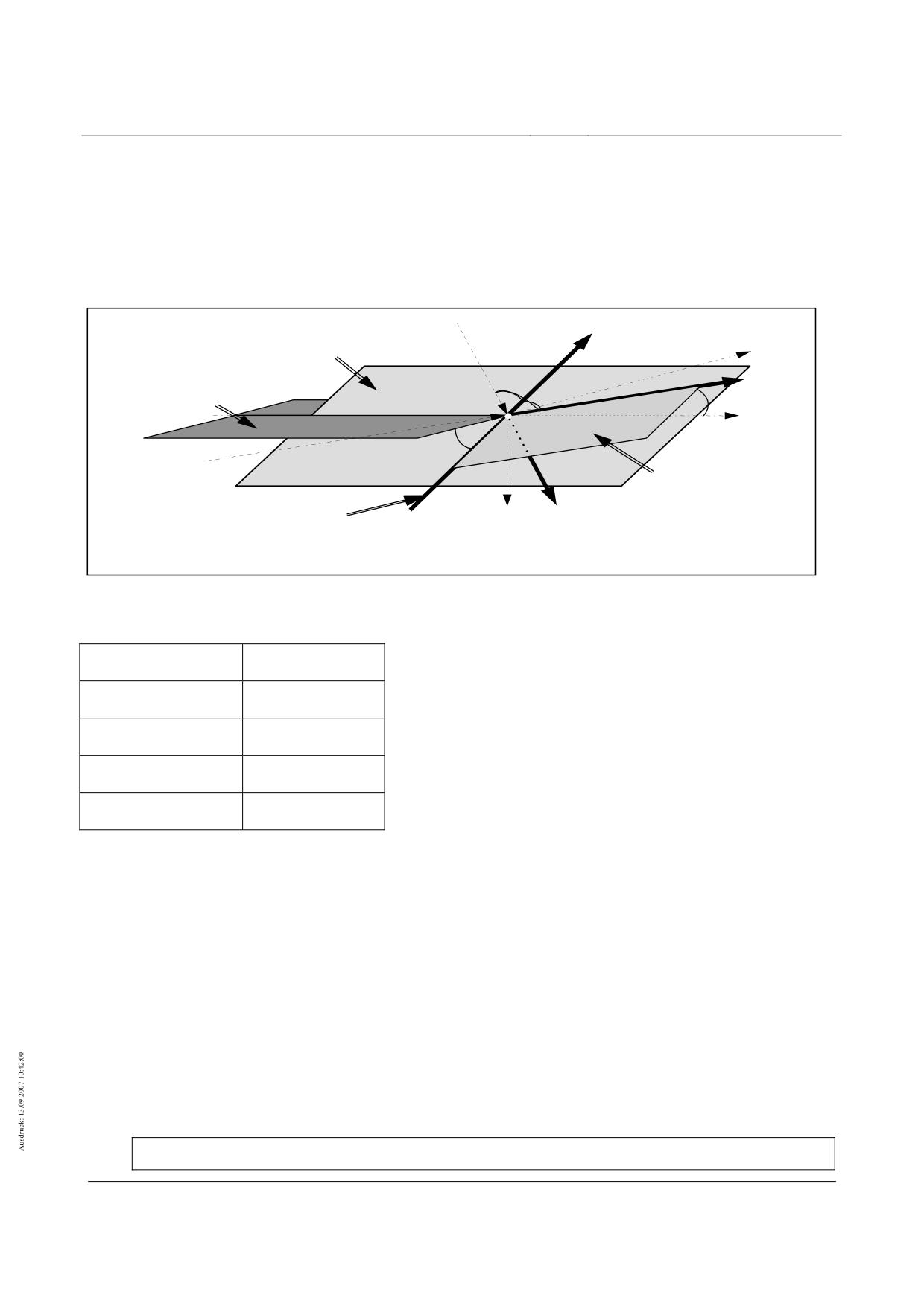
High-speed maglev systems
Maglev Technical Committee
Design principles
Guideway
(4)
The connection between accelerations and track parameters is presented in figure 127. The
possibility of overlapping of track elements is limited by the Rx,z -criterion given in /MSB AG-
FW TRAS/. The value limits of possible combinations are compiled in Annex II-C.
(5)
The maximum possible guideway actions are set down by the limitation of the admissible
accelerations following chapter 0. The acceleration values can deviate downwards project
specifically limitation of the admissible accelerations).
(6)
The equations (3) and (4) also apply for the standing vehicle.
x, ax
Fläche
Rxz
X, a
X
"Gradiente"
y,ay
Fläche
waagrecht,
"0
α
Y,aY
"Grundriß"
RH
β
R
Fläche xy
xy
Gleitleistenebene
z, aZ
Raumkurve
Z, g
RV, K/W
Figure 127 - Connection between accelerations and track parameters
Fläche
Surface
Gradiente
Gradient
Waagrecht “Grundriss”
Horizontal “layout”
Raumkurve
Space curve
Gleitleistenebene
Sliding strip surface
Actions as a consequence of braking and accelerating (Q1/Q2)
z, az
(22) The thrust in each route section and the max. permissible longitudinal force resulting from ma ax
according to Table 91 is to be set as a frequently variable action in the x-direction.
(23) The force in x-direction is location dependent and takes into account acceleration stretches (starting
up and braking), inertia stretches, incline, fall and the aerodynamic travel resistance (incl. headwind).
(24) A force of 110 Kn/middle section with reference to the vehicle weight is to be taken into account as
limit force in x-direction in frequent design situations (see also table 101 line 3).
(25) The actions to be taken into account as a consequence of propulsion (braking/accelerating) are to be
taken from table 101 for max ax = 1.5 m/s² for the various vehicle weights.
Static actions max px,Schub for frequent rating situations from:
Title
High-speed Maglev Systems - Design principles
Guideway - Part II: Design
Doc. no.:
57288
Version
White Paper Issue date
15.02.2007
Page 52
High-speed maglev systems
Maglev Technical Committee
Design principles
Guideway
1
minimum vehicle weight
max px,Q1/Q2,EG = pZ,EG / g ⋅ max ax = 3.2 kN/m
2
medium vehicle weight
max px,Q1/Q2,MG = pZ,MG / g ⋅ max ax = 4.0 kN/m
3
admissible vehicle weight
max px,Q1/Q2,ZG = pZ,ZG / g ⋅ max ax = 4.5 kN/m (value limit)
4
maximum vehicle weight
max px,Q1/Q2,HG = max px, Q1/Q2,ZG
= 4.5 kN/m (value limit)
Table 101 - Maximum forces in x-direction from propulsion and braking
(26) As a rating the value the action px ,Q1/Q2 following (6) is to be applied.
( 6)
px ,Q1/Q2 = max px, Q1/Q2
(27) In the area outside of motor section switching the following is to be applied:
( 7)
px,links = px,rechts = 0,5 ⋅ px
Title
High-speed Maglev Systems - Design principles
Guideway - Part II: Design
Doc. no.:
57288
Version
White Paper Issue date
15.02.2007
Page 53
High-speed maglev systems
Maglev Technical Committee
Design principles
Guideway
(28) During the alternating step method (ASM) 73% of the installed braking or propulsion force or the
above limit value is to be discharged via a beam side in the area of motor section switches. For these
areas the following is to be applied:
( 8)
px,links =
0
and px,rechts = 0,73 ⋅ px
( 9)
bzw. px,links = 0,73 ⋅ px and px,rechts =
0
(29) As a consequence of the centre of gravity distance in the z-direction a moment round the y-axis re-
sults when braking and accelerating which leads to a load in z-direction (see chapter 0).
(30) Additional actions on the lateral guidance rails result through the single side introduction of the actions
following equation (8) and (9). The associated partial magnet forces are to be taken into account in
accordance with chapter 0.
(31) Component dynamics and control dynamics following chapter 0 are to be taken into account.
Actions in y-direction
General
(32) The guidance magnet forces’ points of attack are to be derived from the interface descriptions in chap-
ter 0 (figure 123) and the load arrangements in 0.
Guidance magnet initial loading
(1)
For directional control, guidance magnet forces (tractive forces) are transferred to both sides of the
guideway via the interface guidance magnets-lateral guidance rails (“guidance magnet initial loading”).
As “inner forces” they do not create any reactive forces in the beam supports and they act like a
prestressing force. The maximum guidance magnet initial load is to be applied with py,Vor = 3.6 kN/m.
(2)
The lateral pre load is to be transferred to the other actions in y-direction. The procedure in the trans-
fer is presented in figure 128.
(3)
Component dynamics and control dynamics following chapter 0 are to be taken into account.
Fall 1
Fall 2
Fall 3
Fall 4
Erläuterungen:
py,Vor ; Σpy,Rest
= 0
py,Vor > Σpy,Rest
py,Vor = Σpy,Rest
py,Vor < Σpy,Rest
Führmagnetvorspannung:
F
py,Vor ≡ V
V
l
Vl
Vl
Vl
Vl
Vr= F
Vl
Summe der sonstigen Ein-
F
wirkungen in y-Richtung:
F
F
Σpy,Rest ≡ F
⇒
⇒
⇒
⇒
x
Resultierende Einwirkung in
y-Richtung: Σpy
y
Fahrweg von oben
Vr
Vr
Vr
Vr - F
Vr
Vr-F
Vr
Figure 128 - Transfers with the guidance magnet pre loading
Erläuterungen
Notes
Title
High-speed Maglev Systems - Design principles
Guideway - Part II: Design
Doc. no.:
57288
Version
White Paper Issue date
15.02.2007
Page 54
High-speed maglev systems
Maglev Technical Committee
Design principles
Guideway
Führmagnetvorspannung
Guidance magnet pre loading
Summe der sonstigen Einwirkungen in y-Richtung
Sum of the other actions in y-direction
Resultierende Einwirkung in y-Richtung
Resultant action in y-direction
Fahrweg von oben
Guideway from above
Free lateral acceleration (Q1, Q2)
(33)
The free lateral acceleration ay (centrifugal force) is to applied in accordance with equation (3) and
equation (5) as a further variable action in y-direction as a consequence of the vehicle
(34)
The static actions to be applied are to be established for the individual partial magnets guiding FMTi
from equation (10)
(35)
Component dynamics and control dynamics following chapter 0 are to be taken into account.
(36)
The distribution of the guidance magnet forces along the length of the vehicle corresponding to the
guidance magnet occupation (see figure 123) is to be taken as a percentage via the factors ky,ay,i from
Table 102.
a
k
L
ES/MS
y
y,ay,i
p
=
p
⋅
⋅
⋅
in [kN/m]
( 10)
y,ay,FM T
i
,E G / M G / Z G / H G
Z,EG/MG/ZG/HG
L
g
100
FMT
(37)
As a consequence of the centre of gravity distance of the vehicle (see chapter 0) and the centrifugal
force py,ay there results a rail moment round the x-axis which is passed on into the guideway via the
support magnets. The actions from the free lateral acceleration ± pz,ay,FMTi are to be established with
the help of the equation (11) and table 102 with zFM = 0,17 m for the individual partial support magnets
TMTi.
a
±k
(
s
+
z
)
L
ES/MS
y
z,ay,i
Z
FM
±
p
=
p
⋅
⋅
⋅
⋅
z,ay,TMT
i
,E G / M G / Z G / H G
Z,EG/M G/ZG /HG
( 11)
L
g
100
e
TMT
i
y,TM
in [kN/m]
FMTi
End sections
TMTi
(1) *
2
3
4
5
6
7
BM
10
11
12
13
14
15
16
ky,ay,i [%]
-
7
7
8
7
8
11
-
-
11
8
7
9
8
5
4
ky,ay,i [%]
5
10
6
6
6
7
9
8
6
6
6
6
5
7
7
FMTi
Middle sections
TMTi
1
2
3
4
5
6
7
BM
10
11
12
13
14
15
16
ky,ay,i [%]
4
5
7
8
7
8
11
-
-
11
8
7
8
7
5
4
ky,ay,i [%]
7
7
5
6
5
5
7
8
8
7
5
5
6
5
7
7
* TMT1 conforms as typical extension of TMT2 (see figure 122).
Table 102 - Typical distribution of the magnetic forces from ay over the length of the vehicle
Title
High-speed Maglev Systems - Design principles
Guideway - Part II: Design
Doc. no.:
57288
Version
White Paper Issue date
15.02.2007
Page 55

High-speed maglev systems
Maglev Technical Committee
Design principles
Guideway
Lateral forces from the guidance dynamics (Q5)
(38) Dynamic lateral forces SK for taking into account the guidance dynamics as a result of global guide-
way tolerances of the lateral guidance rails are to be applied according to the following relationship:
⎛
v
⎣km/h⎦ ⎞
Fzg
( 12)
±p
y,SK
= ±⎜1+
⎟
in [kN/m]
⎜
500
⎣km/h⎦
⎟
⎝
⎠
(39) For set down vehicle with vFzg = 0 , py,SK = 0 is to be applied.
(40) The action py,SK is a dynamic action and thus contains the global component dynamics.
(41) Local component dynamics and control dynamics following chapter 0 are to be taken into account.
Reactive forces with small horizontal radii RH (Q6)
(42) With small horizontal radii local reactive forces determined by the vehicle geometry are to be trans-
ferred in y-direction to the other actions from the guidance magnets.
(43) The characteristic reactive forces to be applied for the corresponding horizontal radii are to be taken
from table 103. As an addition to this the distribution of the actions is presented in figure 129.
(44) Component dynamics and control dynamics following chapter 0 are to be taken into account.
py,ZWG,i [kN/m]
End sections
Middle sections
RH = 350 m
RH = 1000 m
RH = 350 m
RH = 1000 m
py,ZWG,1
-
-
18.0
7
py,ZWG,2
21.0
7
0
0
py,ZWG,3
0
0
0
0
py,ZWG,4
1.0
0
6.0
0
py,ZWG,5
2.0
0
1.0
0
py,ZWG,6
-4.5
0
-5
-1
py,ZWG,7
-21.0
-7
-21.0
-6
BM
-
-
-
-
py,ZWG,10
-21.0
-7
-21.0
-6
py,ZWG,11
-4.5
0
-5
-1
py,ZWG,12
1.0
0
1.0
0
py,ZWG,13
7.0
0
6.0
0
py,ZWG,14
0
0
0
0
py,ZWG,15
1.0
0
1.0
0
py,ZWG,16
18.0
7
18.0
7
Interim values may interpolated or extrapolated in a linear way.
Table 103 - Typical reactive forces py,ZWG,i for small horizontal radii
Title
High-speed Maglev Systems - Design principles
Guideway - Part II: Design
Doc. no.:
57288
Version
White Paper Issue date
15.02.2007
Page 56
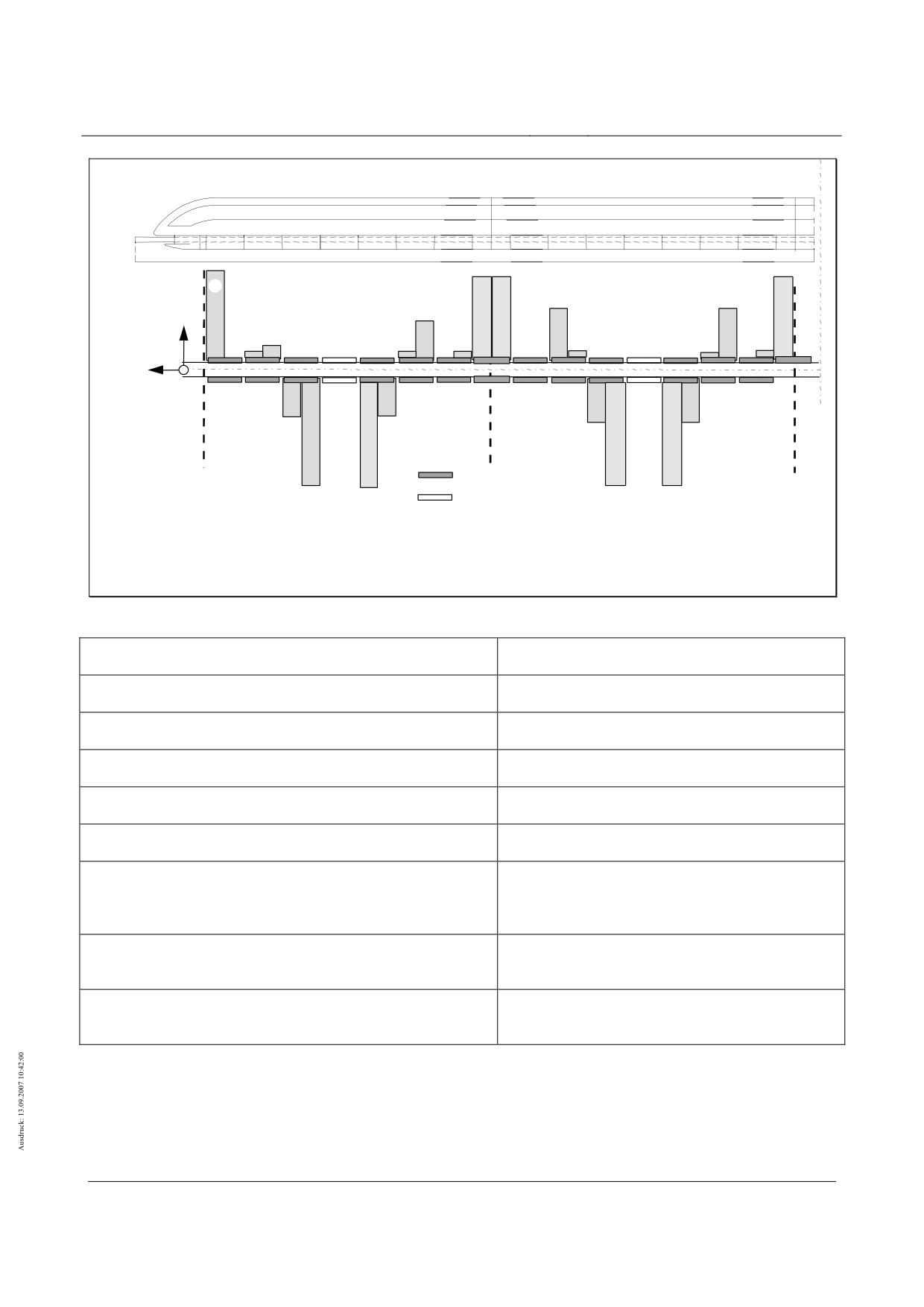
High-speed maglev systems
Maglev Technical Committee
Design principles
Guideway
Endsektionen
Mittelsektionen
16
1
16
2
bogenaußen
4
13
13
y
14
4
5
12
5
14
15
12
15
2
3
3
x
z
6
bogeninnen
6
11
11
= Führmagnet
10
7
10
7
= Bremsmagnet (WSB)
Die Nummern 1..16 entsprechen den in der zugehörgen
Tabelle angegebenen Teilmagnetkräften der Führmagnete:
+ ⇒ Zugkräfte der bogenaußenliegenden Führmagnete
- ⇒ Zugkräfte der bogeninnenliegenden Führmagnete
Figure 129 - Typical distribution of the reactive forces in tight horizontal radii RH
bogenaussen
Outside of curve
bogeninnen
Inside of curve
Endsektionen
End sections
Mittelsektionen
Middle sections
Führmagnet
Guidance magnet
Bremsmagnet
Braking magnet
Die Nummern 1..16 entsprechen den in der zugehörigen Tabelle
The numbers 1..16 correspond to the part magnet
angegebenen Teilmagnetkräfte der Führmagnete:
forces of the guidance magnets in the associated
table:
Zugkräfte der bogenaussenliegenden Führmagnete
Tractive forces of the guidance magnets on the out-
side of the curve
Zugkräfte der bogeninnenenliegenden Führmagnete
Tractive forces of the guidance magnets on the in-
side of the curve
Guidance magnet forces from one sided propulsion
Title
High-speed Maglev Systems - Design principles
Guideway - Part II: Design
Doc. no.:
57288
Version
White Paper Issue date
15.02.2007
Page 57
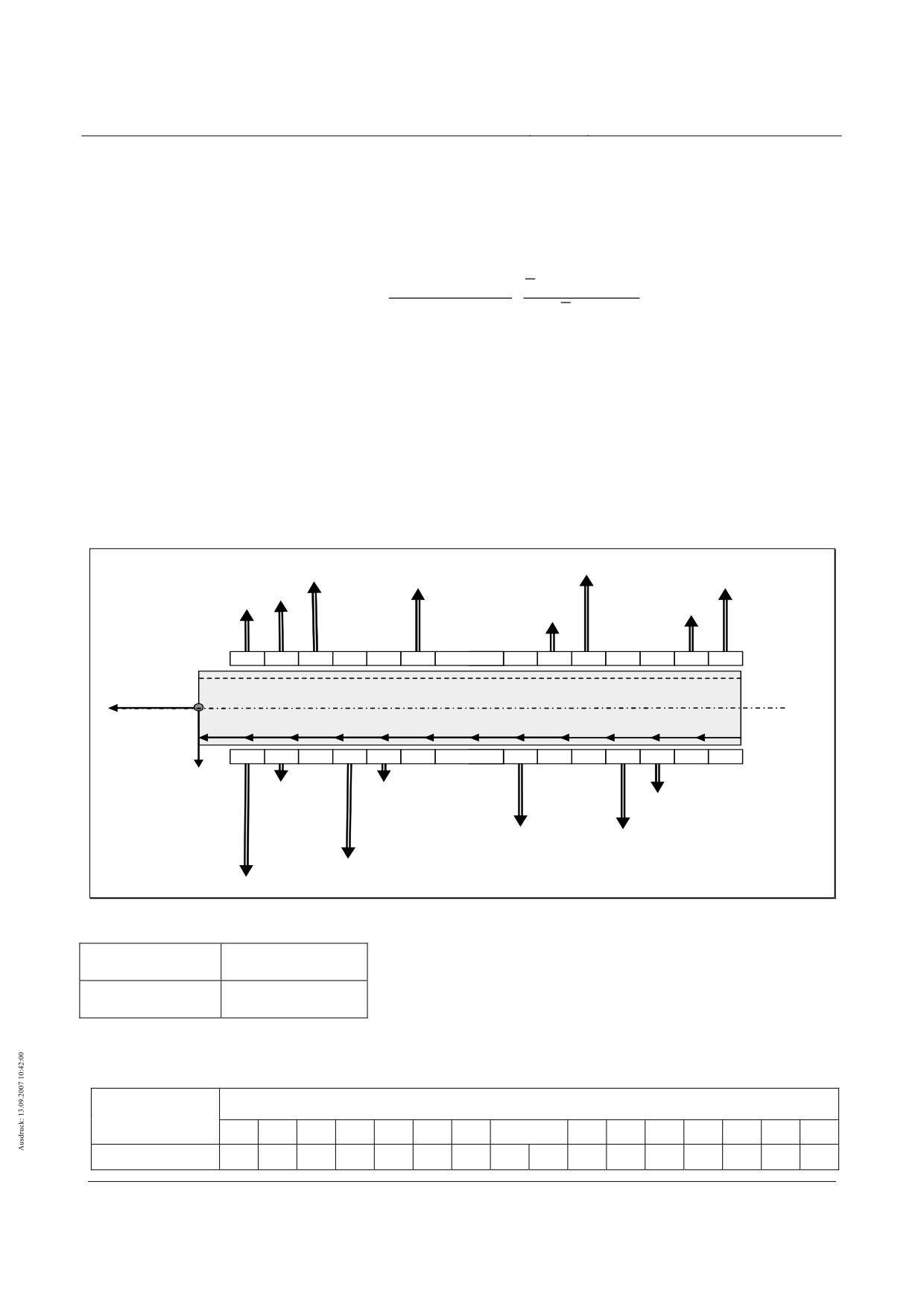
High-speed maglev systems
Maglev Technical Committee
Design principles
Guideway
(7)
The moment round the z-axis from one sided propulsion (e.g. following chapter 0 change
over step process) is introduced to the guideway via the guidance magnets.
(1)
The actions to be applied are to be determined with equation ( 13) and table 104 for the
guidance magnets shown in figure 121, whereby the existing acceleration ax,WSV at point (x)
of the guideway is to be applied.
vorh a
(x) p
x,WSV
Z,EG/MG/ZG/HG
p
=
⋅
⋅
p
y,a
x,WSV
i
,FMT ,EG / MG / ZG / HG
y,a
x,WSV
,i,ZG
0,73
⋅
a
x,max
p
Z,ZG
( 13)
in [kN/m]
Whereby max ax = + 1.5 m/s² or - 1.5 m/s² , ax,WSV (x) ≤ 0.73 ⋅ max ax
and py,axWSV,i,ZG from table 104;
(2)
As a consequence of the mechanical linking of the magnets guidance magnet forces can
work as tractive forces on the right (r)and left (l) side of the beam simultaneously (see figure
130).
(3)
Component dynamics and control dynamics following chapter 0 are to be taken into account.
•
py,axWSV,i,ZG (r)
2
3
4
5
6
7
BM
10
11
12
13
14
15
16
FMTi, (r)
Bug
Beispiel Endsektion
z
x
px,axWSV
y
2
3
4
5
6
7
BM
10
11
12
13
14
15
16
FMTi (l)
py,axWSV,i,ZG (l)
Figure 130 - Typical distribution of the guidance magnets from ax,WSV
Bug
Nose
Besipiel Endsektion
Example end section
End sections
FMTi in
[kN/m]
-
2
3
4
5
6
7
BM
10
11
12
13
14
15
16
py,axWSV,i,ZG (r)
-
2.2
3.7
4.7
0
0
4.5
-
-
0
1.1
5.6
0
0
1.4
4.4
Title
High-speed Maglev Systems - Design principles
Guideway - Part II: Design
Doc. no.:
57288
Version
White Paper Issue date
15.02.2007
Page 58