Design Principles High-speed Maglev System. Information (MSB, 2007) - page 8
High-speed Maglev System
Maglev Technical Commit-
tee
Design principles
Vehicle
•
Annex 5: Noise, Document no.: 72963, /MSB AG-SCHALL/
The documentation on the vehicle consists of the following documents:
•
High-speed Maglev system design principles, vehicle, Part I.: Design principles, Document
no.: 67698, /MSB AG-FZ GEN/
•
High-speed Maglev system design principles, vehicle, Part II.: Design, document no.:
67694, /MSB AG-FZ BEM/
•
High-speed Maglev system design principles, vehicle, Part III.: Kinematic limits, Document
no.: 67650, /MSB AG-FZ KIN/
•
High-speed Maglev system design principles, vehicle, Part IV.: Levitation and guidance
systems, Document no.: 73388, /MSB AG-FZ TRAFÜ/
•
High-speed Maglev system design principles, vehicle, Part V.: Braking system, Document
no.: 73389, /MSB AG-FZ BREMS/
Abbreviations and Definitions
• The abbreviations and definitions supplied in /MSB AG-ABK&DEF/ should be used.
• The following abbreviations apply in addition to /MSB AG-ABK&DEF/:
•
a Braking delay (instantaneous value)
FG Baking force of the vehicle
FBrems
Braking force of the vehicle as a result of the action of the braking equipment
FW Train resistance of the vehicle
FH Holding brake effort
m Vehicle earth
mb Set-down part of the vehicle mass
s Local variable
v speed (instantaneous)
v0 Braking output rate
µH Coefficient of friction for the holding brake function
µH min
Minimum coefficient of friction for the holding brake function on an iced-up guideway
Title
High-speed Maglev system Design principles
Vehicle, Part V, Braking system
Document
73389
Version
White Pa-
Issue date
15.02.2007
Page 7
no.:
per
High-speed Maglev System
Maglev Technical Commit-
tee
Design principles
Vehicle
Legislation, regulations, standards and directi-
ves
• The prescriptive documents listed in /MSB AG-NORM&RILI/ contain definitions that are re-
ferred to in the high-speed Maglev system design principles and have become part of the
high-speed Maglev system design principles. Where prescriptive documents in /MSB AG-
NORM&RILI/ are dated, subsequent changes or revisions of these publications do not ap-
ply. Where references are undated, the latest edition of the prescriptive documents referred
to is applicable.
• The edition of the standards and guidelines to be adhered to in a Maglev project must be
made binding for each specific project.
Identification and mandatory nature of requi-
rements
• The content of the present document is substantially based on the provisions of /DIN 820/ .
• In the following chapters of this document, and in the appendices,
Requirements are shown in standard type
Explanations, guidelines and examples are shown in italic.
•
• Where notes on project-specific regulations are given in this document for individual cases,
(e.g. in a specification or a contractual regulation) this means that the manufacturer and the
contractor must consult the approvals authorities and come to an agreement.
Title
High-speed Maglev system Design principles
Vehicle, Part V, Braking system
Document
73389
Version
White Pa-
Issue date
15.02.2007
Page 8
no.:
per
High-speed Maglev System
Maglev Technical Commit-
tee
Design principles
Vehicle
Definitions (vehicle-specific)
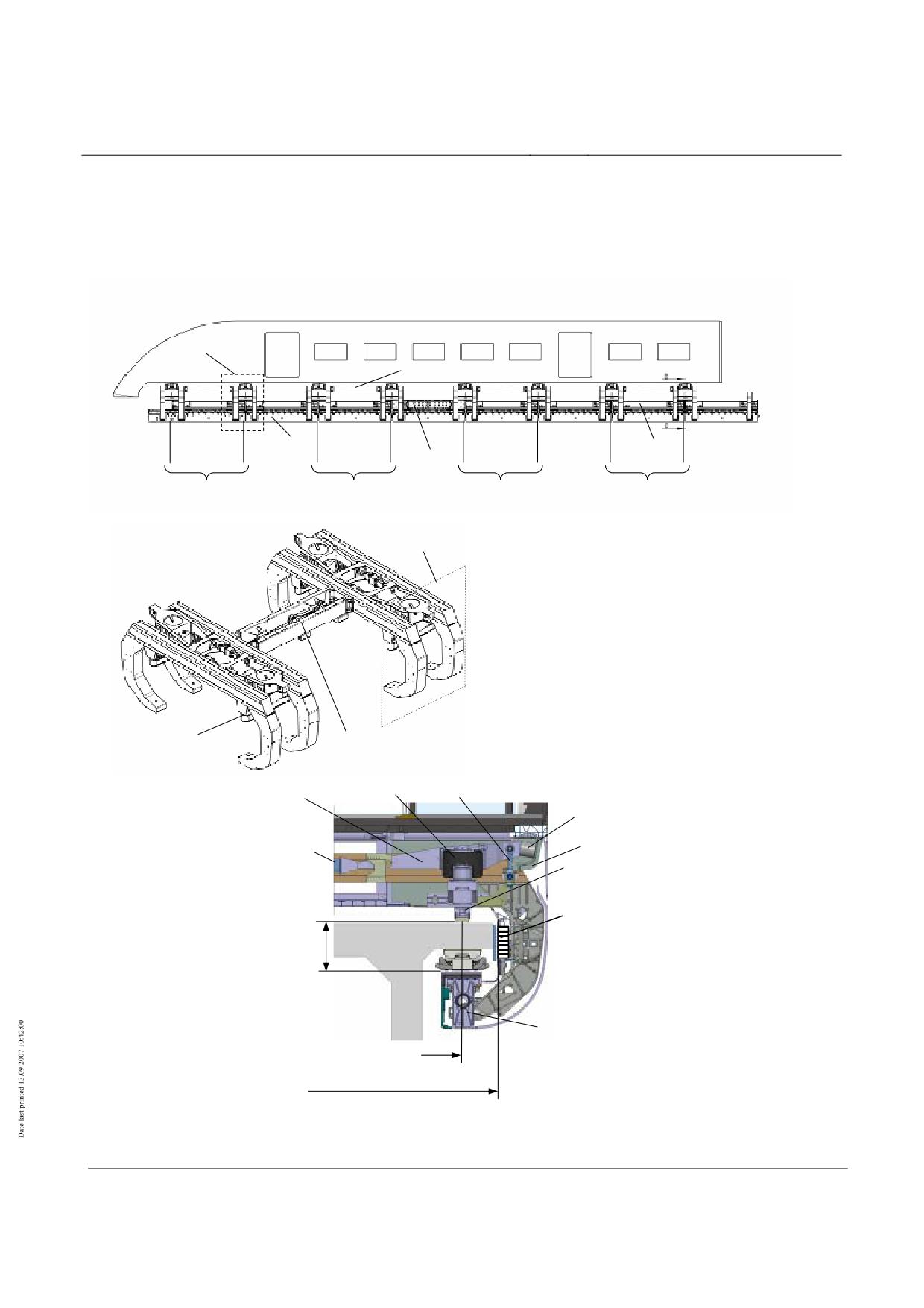
SR
Longitudinal connector
TM
FM
BM
1
2
3
4
5
6
7
8
SG1
SG2
SG3
SG4
Levitation chassis
SR
SG
= Levitation chassis (LC)
(without magnets)
SR
= Levitation undercarriage (2 levitation
frames +connecting parts)
TM = Support magnet
FM = Guidance magnet
BM = Braking magnet
TK = Support skid
WK = Carriage body
TK
Longitudinal connector
Pneumatic
Pendulum
Pneumatic spring
Additional Y spring
Roll stabiliser
Z support for carriage body
TK
BM
Vehicle
frame dimension
TM
Support magnet centre distance =
support skid centre distance
Vehicle guideway width
Title
High-speed Maglev system Design principles
Vehicle, Part V, Braking system
Document
73389
Version
White Pa-
Issue date
15.02.2007
Page 9
no.:
per
High-speed Maglev System
Maglev Technical Commit-
tee
Design principles
Vehicle
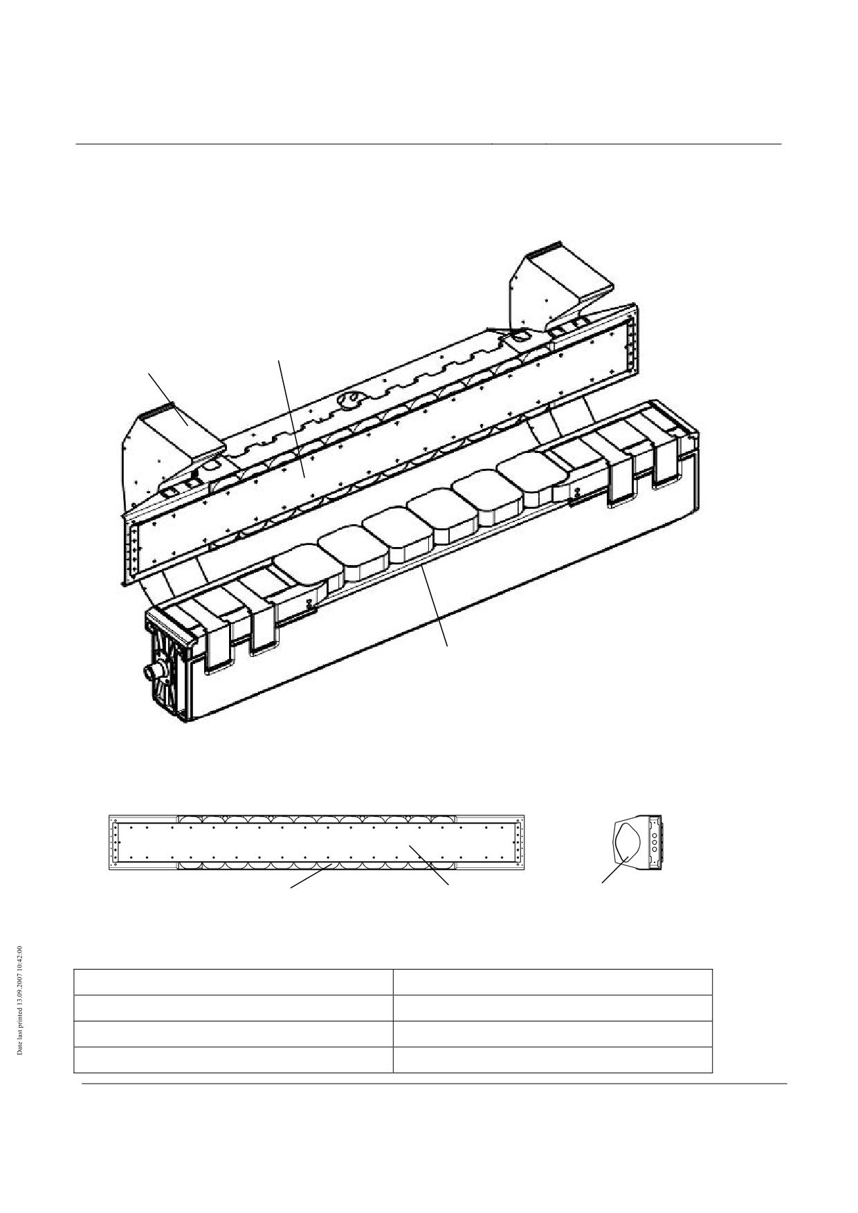
Fig. 93: Side view and cross-section of a vehicle, identifying the braking equipment (schematic)
Braking magnet
Levitation frame
Support magnet
Fig. 94: Magnet module (example)
Gleitplatten
Magnetrücken
Bremsmagnet
Bremspol
Fig. 95: View of a braking magnet (example), definition of the essential components
Bremsmagnet
Braking magnet
Bremspol
Braking pole
Gleitplatten
Sliding plates
Magnetrücken
Rear of magnet
Title
High-speed Maglev system Design principles
Vehicle, Part V, Braking system
Document
73389
Version
White Pa-
Issue date
15.02.2007
Page 10
no.:
per
High-speed Maglev System
Maglev Technical Commit-
tee
Design principles
Vehicle
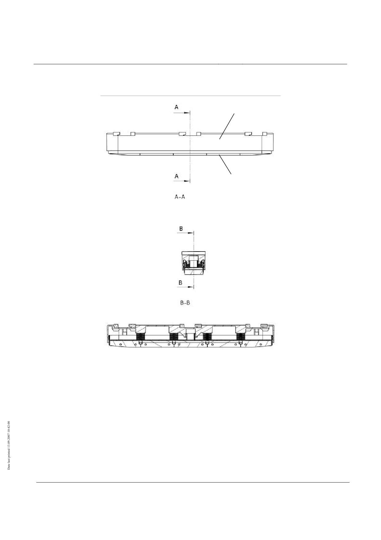
Housing
Sliding surface
lining
Fig. 96: Support skid (example)
Title
High-speed Maglev system Design principles
Vehicle, Part V, Braking system
Document
73389
Version
White Pa-
Issue date
15.02.2007
Page 11
no.:
per
High-speed Maglev System
Maglev Technical Commit-
tee
Design principles
Vehicle
General requirements of the braking system
Subsystems and equipment
• The description in /MSB AG-GESAMTSYS/ is applicable.
• The following brakes are available for the vehicle:
Braking function of the long stator propulsion system, used in fault-free condition (operating brake);
Safety brake, controlled by BLT devices in the vehicle.
• The "long stator propulsion" braking function is not covered in this document (see /MSB
AG-GESAMTSYS/).
• This design principles controls the demands that the vehicle makes on the braking system
(safe brake) and their actions on the guideway. The propulsion system shutdown and the
vehicle's own braking system are controlled by the operational control system, which also
prevents inadmissible superimposition effects. This design principles does not cover these
functions11.
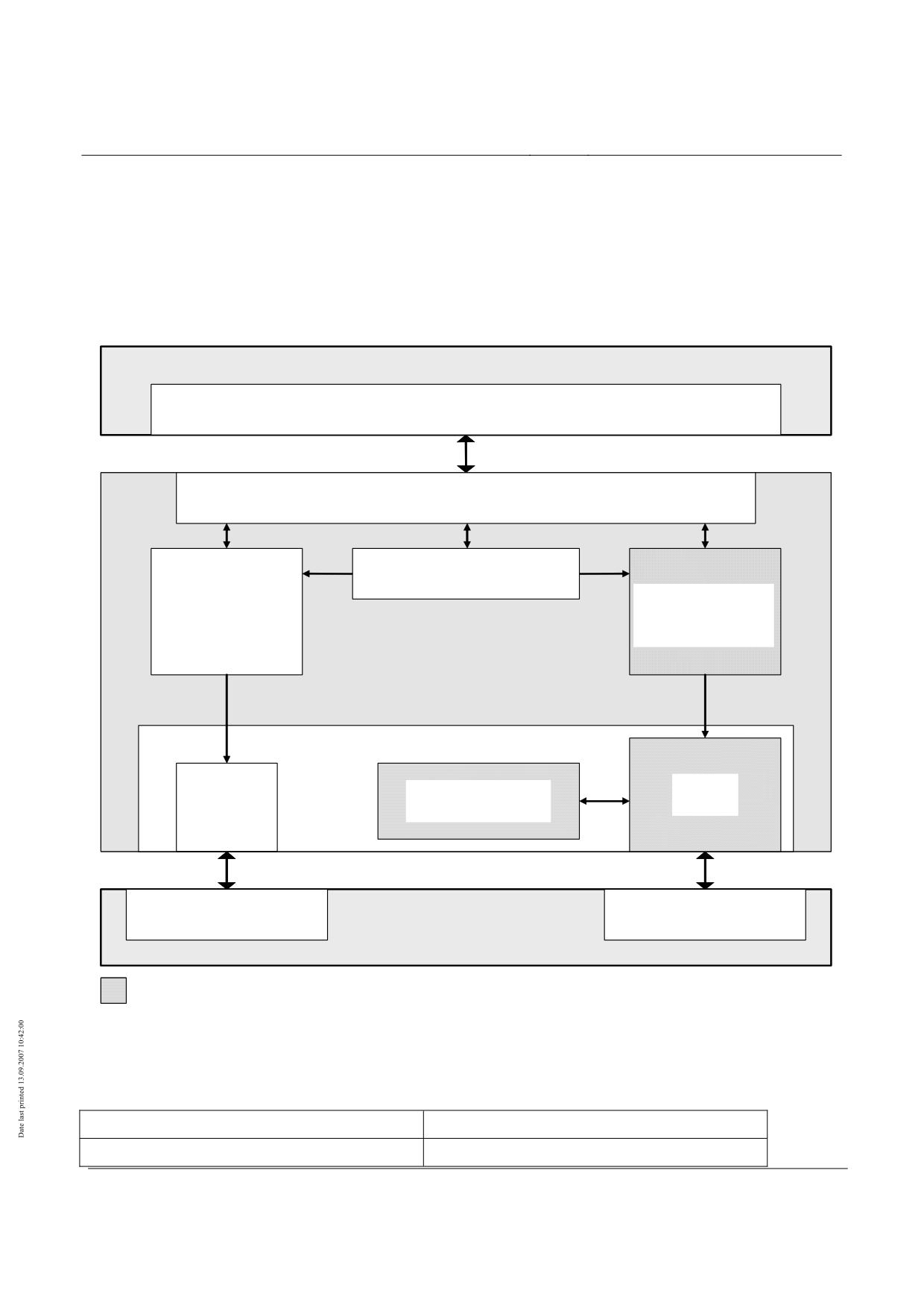
• Examples of the subsystems and equipment used in the safety brake are defined in Fig. 97.
In this example the control and monitoring of the safe brake that the BLT has to implement
is done in the vehicle using the following subsystems and equipment:
The control signals from the BLT to activate the braking function and to control the effect of braking are
transmitted to the braking magnet control devices.
The braking magnet control devices control the current in the braking magnets and perform distributed
monitoring of the brake devices concerned.
The monitoring signals from the brakes of the magnet control devices are transmitted to the BLT.
The braking magnets generate speed-dependent eddy currents in the lateral guidance rails of the
guideway and these result in deceleration forces on the braking magnets. In addition the braking
magnets create forces of attraction on the lateral guidance rails. In the lower speed range the brak-
ing magnets apply themselves because of the forces of attraction on the lateral guidance rails and
generate frictional forces between the sliding plates of the braking magnets and the lateral guidance
rails.
The forces acting on the brake are directed into the vehicle by the guidance parts and structural parts of
the brake.
Immediately before the vehicle comes to a standstill, the BLT switches the brake off and the vehicle is
set down by the support skids on the sliding surface, acting on control signals from the BLT to the
support magnet control devices.
The support skids take over the function of a holding brake.
The monitoring signals from the on-board networks and the support magnet control devices are trans-
mitted to the BLT.
11The design principles describes the construction requirements for the safe brake that are not pro-
ject-dependent and are based on specific construction features.
Title
High-speed Maglev system Design principles
Vehicle, Part V, Braking system
Document
73389
Version
White Pa-
Issue date
15.02.2007
Page 12
no.:
per
High-speed Maglev System
Maglev Technical Commit-
tee
Design principles
Vehicle
• The generation of the braking force as per chapter 0 (in Fig. 97 Braking magnet, structural
guidance parts for the brake, braking magnet control equipment and the control and super-
vision of the braking effect in accordance with chapter 0 (in Fig. 97 Transmission of brake
control and monitoring signals from and to the BLT, generation of safety-relevant status in-
formation in the magnet control equipment) are part of this design principles (/MSB AG-FZ
BREMS/).
Mobile Einrichtungen der BLT
Steuerung / Überwachung Sichere Bremse
Übertragung von sicherheitsrelevanten
Steuerungs- und Überwachungssignalen
Bordnetze
Magnetregel-
Magnetregel-
Einrichtungen
einrichtungen
Tragen
Bremsen
Fahrzeug
Trag-/ Führstruktur
Brems-
Struktur- / Anlenk-
Trag-
magnet
teile Bremse
kufe
Gleitebene
Seitenführschiene
Fahrweg
Bremseinrichtungen
Fig. 97: Subsystems and equipment involved in safe braking (example)
Mobile Einrichtungen der BLT
Mobile BLT equipment
Steuerung/Überwachung sichere Bremse
Control/monitoring of the safe brake
Title
High-speed Maglev system Design principles
Vehicle, Part V, Braking system
Document
73389
Version
White Pa-
Issue date
15.02.2007
Page 13
no.:
per
High-speed Maglev System
Maglev Technical Commit-
tee
Design principles
Vehicle
Übertragung von sicherheitsrelevanten Steuerungs-
Transmission of safety-relevant control and monito-
und Überwachungssignalen
ring signals
Magnetregel-Einrichtungen Tragen
Magnet control equipment for support
Bordnetze
On-board power supplies
Magnetregel-Einrichtungen Bremsen
Magnet control equipment for brakes
Fahrzeug
Vehicle
Tragkufe
Support skid
Struktur/Anlenkteile Bremse
Structural and pivoting parts for brakes
Bremsmagnet
Braking magnet
Gleitebene
Sliding surface
Fahrweg
Guideway
Seitenführschiene
Lateral guidance rail
Bremseinrichtungen
Braking equipment
Title
High-speed Maglev system Design principles
Vehicle, Part V, Braking system
Document
73389
Version
White Pa-
Issue date
15.02.2007
Page 14
no.:
per
High-speed Maglev System
Maglev Technical Commit-
tee
Design principles
Vehicle
• Functions of the BLT that are necessary for the use of safe braking
Control and supervision of brake testing,
Control and supervision of safe braking,
Maximum profile monitoring,
Minimum profile monitoring,
Safe location,
Safe propulsion shutdown,
• are in the design principles for the BLT (/MSB AG-BLT/).
• The levitation and guidance structure and the support and guidance magnet regulation de-
vices are dealt with in the design principles for the levitation and guidance system (/MSB
AG-FZ TRAFÜ/).
• The design of the structural components of the brake is given in /MSB AG-FZ BEM/.
Operation
• The vehicle's own safe brake must be designed in such a way that the vehicle can brake
independently at a defined stopping place using its own operational control system equip-
ment.
• The vehicle's own safe brake must have the following functions:
BLT can actuate the brake at any time,
BLT can control the magnitude of the braking effect,
Stopping brake function.
• Sections 13 and 20 of the MbBO apply to the stopping brake function. The conversion must
be certified separately for each project. The requirements of /MSB AG-GESAMTSYS/ are
applicable. A stopping position, once adopted, must be maintained.
• Braking ability is determined by the speed-dependent effective braking power of the vehicle
FG when long stator propulsion is switched off and by the brake winding time te after activa-
tion by the BLT.
• The following applies in general for FG:
•
FG = FBrems + FW
where FBrems : Braking force of the vehicle as a result of the action of the braking equipment
FW: Train resistance of the vehicle
• Braking ability must be verified by means of tests.
• The speed-dependent braking force for a given vehicle mass m is calculated as
•
FG (v) = a (v) ⋅ m .
Title
High-speed Maglev system Design principles
Vehicle, Part V, Braking system
Document
73389
Version
White Pa-
Issue date
15.02.2007
Page 15
no.:
per
High-speed Maglev System
Maglev Technical Commit-
tee
Design principles
Vehicle
• The train resistance FW must be verified by means of suitable levitation tests with the vehi-
cle not propelled and not braked in the same way as FG .
• The stopping brake function can be achieved by setting the vehicle down on the support
skids.
• The stopping brake force FH is determined by the set-down proportion of the vehicle mass
mb and the coefficient of friction µH acting on the area of contact between the guideway and
the vehicle.
• The stopping brake function is present when the stopping brake force is greater than the
force acting on the stationary vehicle in the x direction. This is made up of the incline output
force during longitudinal inclination and the aerodynamic force due to wind in the x direc-
tion.
• When certifying the stopping brake function, a project-specific safety factor > 1 must be
taken into account.
• An example of the maximum and minimum braking characteristics that can be achieved
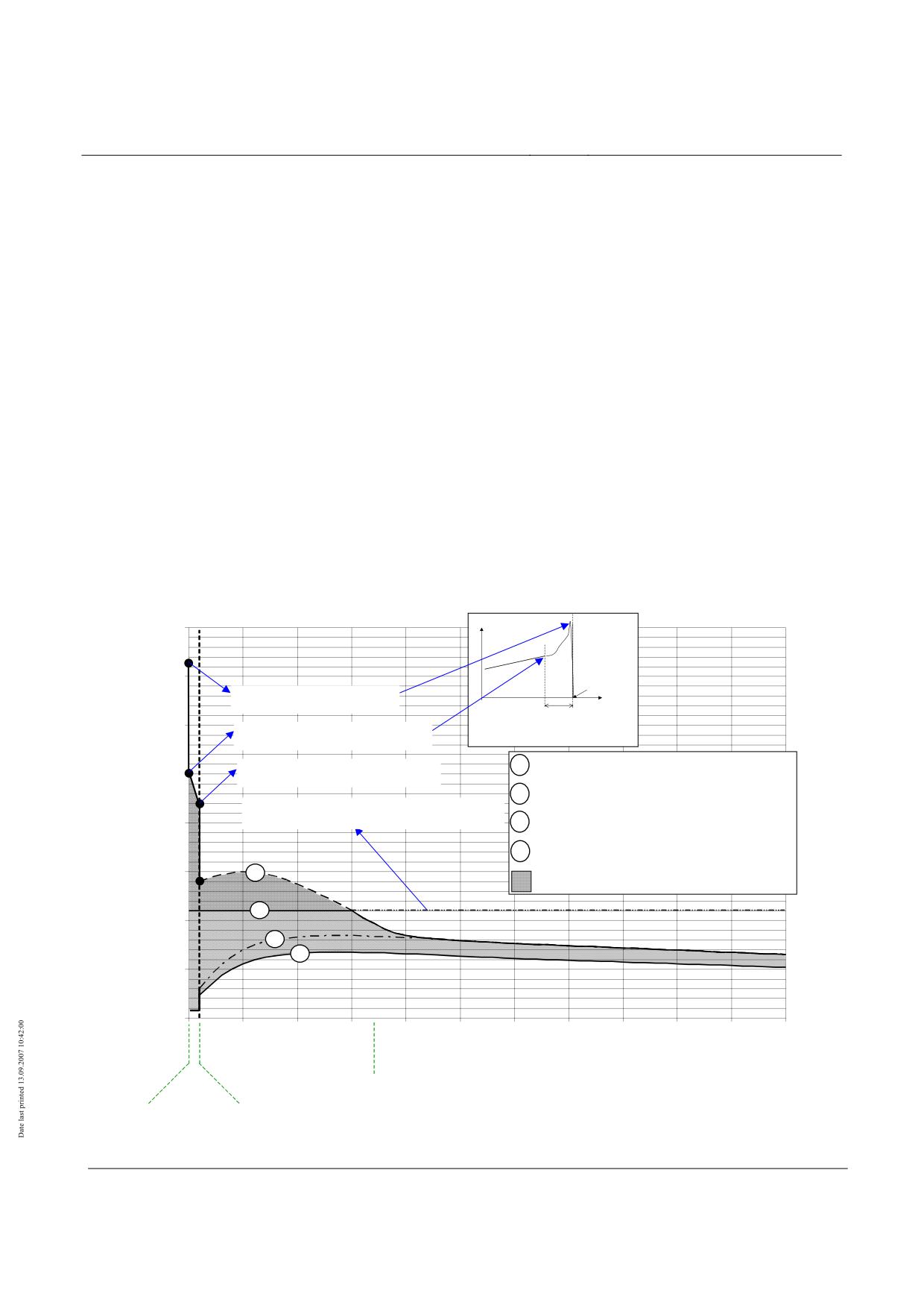
with the safe braking system for a vehicle section is given in Fig. 98.
• For each project the limits must be balanced against the requirements of the BLT and the
design of the guideway. The project-specific defined values must be adhered to.
360 kN
F
Bremskraft
[kN/Sektion]
250 kN
350
v = 0 km/h
Fx = 360 kN/Sektion (Haftreibung)
max. dynamische Bremskraft
t
Übergangsbereich:
300
Gleitreibung → Haftreibung
Fx = 250 kN/Sektion
100 ... 200 ms
Ausgleiten bei Übergang zur Haftreibung
Maximale Bremskennlinie
Fx = 215 kN/Sektion
1
250
(Grundlage zur Bemessung von Fahrzeug und Fahrweg)
Aufsetzen der Tragkufen aus Gleitreibung
2
Grenzlinie für zulässige Verzögerung mit 1,5 m/s²
Fx = 110 kN/Sektion (entspricht der Bremsverzögerung
200
1,5 m/s² bei zulässigem Fahrzeuggewicht)
3
Minimale Bremskraft bei vereistem Fahrweg
Minimale Bremskennlinie
4
(Grundlage für das sichere Bremsprofil)
150
1
Kraft bei außergewöhnlicher Einwirkung
2
100
3
4
50
0
0
50
100
150
200
250
300
350
400
450
500
550
Bremsmagnet an
Bremsmagnet
Geschwindigkeit
Seitenführschiene anliegend
berührungsfrei
[km/h]
Ausgleiten
Bremskraft aus
auf Tragkufen
Wirbelstrombremse
Title
High-speed Maglev system Design principles
Vehicle, Part V, Braking system
Document
73389
Version
White Pa-
Issue date
15.02.2007
Page 16
no.:
per
High-speed Maglev System
Maglev Technical Commit-
tee
Design principles
Vehicle
Fig. 98: Braking characteristic for the safe brake for a vehicle section (Figure 10 taken from chapter 8.5 of /MSB AG-
GESAMTSYS/)
Bremskraft [kN /Sektion]
Braking force [kN/section]
Fx = 360 kN/Sektion (Haftreibung)
Fx = 360 kN/section (stiction)
max. dynamische Bremskraft
Max dynamic braking force
Fx = 250 kN/Sektion
Fx = 250 kN/section
Ausgleiten bei Übergang zur haftreibung
Slip on transition to stiction
Fx = 215 kN/Sektion
Fx = 215 kN/section
aufsetzen der Tragkufen aus Gleitreibung
Support skids applied by sliding friction
Fx = 110 kN/Sektion
Fx = 110 kN/section
(entspricht der Bremsverzögerung 1,5 m/s2 bei zu-
(equivalent to braking delay of 1.5 m/s2 for permis-
lässigem Fahrzeuggewicht)
sible vehicle weight)
Übergangsbereich: Gleitreibung Æ Haftreibung
Transition area: sliding friction Æ stiction
Maximale Bremskennlinie (Grundlage für Bemes-
Maximum braking characteristic (Design basis for
sung fon Fahrzeug und Fahrweg)
vehicle and guideway)
Grenzlinie für zulässiger Verzögerung mit 1,5 m/s2
Threshold for permissible braking at 1.5 m/s2
Minimale Bremskraft bei vereistem Fahrweg
Minimum braking force for iced-up guideway
Minimale Bremskennlinie
Minimum braking characteristic
Kraft bei außergewöhnlicher einwirkung
Force in the event of accidental action
Ausgleiten auf Tragkufen
Slip on support skids
Bremsmagnet an Seitenführscheine anliegend
Braking magnet adjacent to lateral guidance rail
Bremskraft aus Wirbelstrombremse
Braking force from eddy current brake
Bremsmagnet berührungsfrei
Braking magnet not in contact
Geschwindigkeit
Speed
Design and ratings
• The loads that are borne by the structural components and pivots of the equipment produc-
ing the braking force must be taken into account, using the Vehicle design principles, Part II
/MSB AG-FW BEM/, during the design process.
• The loads specific to the project must be documented.
• Proof of load-bearing capability (general stress certificate) and fatigue resistance according
to the requirements set out in Part II /MSB AG-FW BEM/ must be provided for the compo-
nents that transfer the load.
• The braking elements must take all of the geometric constraints in accordance with /MSB
AG-FW GEO/ fully into account. At the same time it must be ensured that the action of
braking has no effect on the permitted surface deviations that would place the system at
risk.
Title
High-speed Maglev system Design principles
Vehicle, Part V, Braking system
Document
73389
Version
White Pa-
Issue date
15.02.2007
Page 17
no.:
per
High-speed Maglev System
Maglev Technical Commit-
tee
Design principles
Vehicle
Safety requirements
•
The systems relevant to safety must be planned and certified to /DIN EN 50126/ as a gen-
eral rule.
•
Fig. 99 and Fig. 100 give examples of a structure for this task.
•
The control and operation of the safe brake with spot braking must be safe over the entire
speed range for its lifetime (Safe-Life). The permissible failure rate for the safe brake over
an assumed period of operation (being driven and at a standstill) must be determined by a
risk analysis.
•
Information on methods of performing the risk analysis is given in /prEN 50,126-2/ and
/prR009-004/.
•
The speed range must include the maximum speed according to the maximum trip profile
right down to a standstill. The speed range can be covered by one or more braking sys-
tems, e.g. an eddy current system combined with a friction brake.
•
The safe life requirement must cover the most unfavourable specified boundary conditions
such as maximum load, following wind, descent, actions from the primary environment, par-
ticularly wintry weather and lightning, and also technical faults and breakdowns.
•
To achieve the required failure rate the safe brake can be executed with redundant braking
equipment. Breakdowns in the redundant safe brake or a reduction in braking force due to
technical faults or breakdowns must not affect the safe-life qualities of the safe brake.
•
Certification of the safe-life property must be performed using a suitable method of analy-
sis, e.g. a fault tree analysis before the system is commissioned. This theoretical certificate
must be backed up by experimental verification of the assembly failure rates assumed in
the analysis and by practical tests to demonstrate the failure behaviour in the event of the
failure of assemblies. The analysis must include a common cause fault analysis.
•
A safety certificate including risk analysis to /DIN EN 50126/ is required for the safe brake.
•
The requirements for and tests on the equipment for producing the braking force are given
in chapter 0.
•
The requirements for and tests on the equipment for controlling and monitoring the braking
force are given in chapter 0.
•
The SIL level according to /DIN EN 50129/ for the electronic equipment for producing the
braking force and for controlling and monitoring it must be determined on the basis of the
risk analysis and must be taken into account when performing the certification.
•
The level of the safety requirements for the software in the braking system that has been
determined on the basis of the risk analysis must be taken into consideration when per-
forming the certification to /DIN EN 50128/.
•
A suitable analysis must include consideration of at least the following faults:
Fault in the on-board energy supply,
Anticipated or delayed execution of a set-down command,
System failure (of software or hardware),.
Title
High-speed Maglev system Design principles
Vehicle, Part V, Braking system
Document
73389
Version
White Pa-
Issue date
15.02.2007
Page 18
no.:
per
High-speed Maglev System
Maglev Technical Commit-
tee
Design principles
Vehicle
Untimely lifting of the vehicle.
Requirements for the on-board energy supply
• The system characteristics of the safe brake set functional and safety-relevant require-
ments for the on-board energy supply and proof is required that these have been met, see /
MSB AG-FZ TRAFÜ/.
• In order to perform forced braking with the safe brake an uninterruptible power supply must
be provided. This must take account of the most adverse environmental and operating con-
ditions that have been specified.
Requirements for the execution of a set-down command.
• The set-down command must be generated in such a way - and must be linked by a logical
AND with the speed determined independently in each levitation and guidance unit in such
a way - that the command to set down can only be decentrally effective when the vehicle
speed is lower than the permitted set-down speed.
• A certificate is required for the set-down control to the effect that the set-down command
can only become effective below the set-down speed and, with sufficient probability, also in
the event of all foreseeable failures.
Systematic faults in the braking system
• Certification that systematic faults are sufficiently unlikely or that their effects are under con-
trol is required in accordance with /DIN EN 50129/. This applies to the hardware and, if pre-
sent, the software of the equipment that is relevant to safety in the measurement, control,
regulation and monitoring systems of the magnet regulating circuits of the safe brake.
• Diagnostic and control equipment should be provided separately as part of the hardware
and software.
•
Taking friction pairing into account
Braking magnet / lateral guidance rail,
• The mutual action of the forces from the braking magnet and lateral guidance rail compo-
nents guarantees the effectiveness of the safe brake. The braking effect is created by an
eddy current effect and, in the lower speed range, by mechanical friction.
• The normal forces, frictional characteristics and surface pressure acting between the lateral
guidance rail and sliding plate must be taken into account during design work.
• Wear on the sliding plates must be taken into account in the maintenance schedule.
• The properties of the frictional pairing of sliding plate and lateral guidance rails must be de-
fined and certified for each project. Suitable test rig results can be used for this.
Title
High-speed Maglev system Design principles
Vehicle, Part V, Braking system
Document
73389
Version
White Pa-
Issue date
15.02.2007
Page 19
no.:
per
High-speed Maglev System
Maglev Technical Commit-
tee
Design principles
Vehicle
Support skids / sliding surface
• The support skid and sliding surface come into mechanical contact when the magnetic levi-
tation function is interrupted.
• This happens
when the vehicle is set down,
when the levitation system is in emergency running mode,
as a contributory braking function of the safe brake at low speeds, e.g. ≤ 10 km/h (project-specific
figure),
as a stopping brake function.
• Wear on the support skids must be taken into account in the maintenance schedule.
• The properties of the frictional pairing of support skid and sliding surface must be defined
and certified for each project. Suitable test rig results can be used for this.
Title
High-speed Maglev system Design principles
Vehicle, Part V, Braking system
Document
73389
Version
White Pa-
Issue date
15.02.2007
Page 20
no.:
per
High-speed Maglev System
Maglev Technical Commit-
tee
Design principles
Vehicle
Requirements for the braking equipment
Generation of braking force
Properties and functions
• The braking forces of the safe brake are generated by:
Braking systems that give rise to braking forces via the interface with the guideway,
Braking systems that give rise to a stopping force via the interface with the guideway when the
vehicle is at a standstill.
Effect of failure
• The failure of one braking system must not adversely affect the operation of the other brak-
ing systems.
• The risk of the following failures occurring within the braking systems per year and per ve-
hicle, which must be determined in advance in a risk analysis, must not exceed:
Failures that lead to the partial or complete activation of the safe brake by the BLT without a com-
mand,
Failures that lead to the defined maximum braking force being exceeded,
Failures that lead to the defined minimum braking force being exceeded.
• Where they interact with the levitation and guidance system, failures of brake systems must
be taken into account in the design and execution of the levitation and guidance system.
• Where they interact with the operation of the safe brake, failures in the levitation and guid-
ance system must be taken into account in the design and execution of the braking sys-
tems.
Failure reporting
• In addition to notification from and to the BLT, failures in the braking systems must be fail-
safe.
• Where monitoring devices that are relevant to safety do not automatically report failure, pe-
riodic functional tests / inspections must make failures obvious.
• The times of failure reporting that are required in order to comply with the preset failure rate
according to the risk analysis must be adhered to.
• The test criteria and intervals must be determined by means of a suitable analysis, e.g. fault
tree analysis, FMEA
Certificates
• A qualification test with prototypes must be performed on the braking systems to certify the
operation, failure behaviour, reporting of failures and environmental resistance.
Title
High-speed Maglev system Design principles
Vehicle, Part V, Braking system
Document
73389
Version
White Pa-
Issue date
15.02.2007
Page 21
no.:
per
High-speed Maglev System
Maglev Technical Commit-
tee
Design principles
Vehicle
• the speed-dependent curves for braking power FBrems, both at full availability and also at a
specified maximum number of failed brake circuits , and the train resistance FW must be
certified by performing tests on a representative vehicle under defined environmental condi-
tions and rated load.
• The speed-dependent curve of the minimum effective braking force FBrems under the most
unfavourable environmental conditions, rated load and failure conditions can be obtained
by calculation.
• The braking force certificate must take into account those failures that are within the ac-
ceptable failure rate according to the risk analysis (see chapter 0).
• A suitable analysis must be carried out to certify the safe life function, e.g. fault tree analy-
sis. The analysis must include a common cause fault analysis.
• A suitable analysis, e.g. a fault tree analysis, must show that the following events have a
risk of occurring per year and per vehicle that is to be determined beforehand in a risk
analysis:
Full or partial application of the brakes without a command or control from the BLT,
Failure to reach a required braking force or exceeding the maximum permitted braking force over
the whole of the speed range including standstill.
• Failure behaviour must be demonstrated in tests that simulate assembly failures.
• The reliability of the electronic braking systems must be verified by determining the MTBF
from the evaluation of life cycle data on representative assemblies during operation.
• The compatibility of the MTBF verified from life cycle data with the forecast statements of
the analysis must be demonstrated.
Title
High-speed Maglev system Design principles
Vehicle, Part V, Braking system
Document
73389
Version
White Pa-
Issue date
15.02.2007
Page 22
no.:
per
High-speed Maglev System
Maglev Technical Commit-
tee
Design principles
Vehicle
Control and monitoring of the braking effect
Properties and functions
• The safety-relevant control and monitoring functions of the safe brake include:
transmission of control commands from the BLT to the baking systems in order to activate the
braking function and control the braking effect
generation of safety-relevant status information to monitor the braking systems and transmission of
this information to the BLT.
• This design principles does not cover non-safety-relevant status information (e.g. diagnostic
messages).
Behaviour in the event of failure
• An individual failure of the control / monitoring systems must not lead to the loss or limita-
tion of a safety-relevant control and monitoring function.
• The failure of a safety-relevant control / monitoring system that is due to the multiple failure
of redundant assemblies must lead to an automatic failsafe system reaction.
• The triggering of this failsafe system reaction is guaranteed by the operational control sys-
tem and is not part of this design principles.
Certificates
• Qualification tests of the assemblies must be carried out with prototypes or on a represen-
tative vehicle.
• The control and monitoring equipment must be taken into account in the analysis to show
the probability of occurrence of an insufficient or unforeseen application of the brakes (see
chapter 6.1). The analysis must include a common cause fault analysis.
Title
High-speed Maglev system Design principles
Vehicle, Part V, Braking system
Document
73389
Version
White Pa-
Issue date
15.02.2007
Page 23
no.:
per
High-speed Maglev System
Maglev Technical Commit-
tee
Design principles
Vehicle
Actions of the braking equipment on the guideway
General
• The forces given below correspond to the characteristic values of the actions of the vehicle
on the guideway at the vehicle-guideway interfaces.
Types and combinations of actions
•
The actions of the braking system on the guideway act upon the following interfaces:
•
•
Braking magnet - lateral guidance rail,
•
Support skid - sliding surface
•
The forces acting on the guideway are the result of the following functions:
•
•
magnetic braking effect caused by the eddy currents induced in the lateral guidance rails by
the braking magnet,
•
magnetic tensile force on the lateral guidance rails as reaction rails of the braking magnets,
•
mechanical braking effect owing to friction between the braking magnet and the lateral
guidance rail,
•
mechanical braking effect owing to friction between the support skid and the sliding surface.
•
The effect of weathering on the magnetic braking effect can be disregarded.
•
The magnetic braking effect is influenced by variations in environmental conditions via the
effective coefficient of friction.
•
The actions of the braking systems on the structure and the force introduction into the levi-
tation and guidance system must be taken into consideration in accordance with chapter 0
when designing the assemblies.
•
The actions on the guideway must be taken into account in the guideway design specifica-
tions as variable and/or unusual actions from the vehicle.
•
To ensure that the actions arising from operation of the vehicle that are assumed in the
guideway design specifications agree well enough with actions arising in practice, the val-
ues given in chapter 0 for the forces transmitted by the vehicle must not be exceeded (per-
missible tolerance when verifying the magnitude of the actions is 5%).
•
The magnitude of the characteristic values of the actions must be set down in a mandatory
project-specific specification for every application.
•
The magnitude of the actions must be demonstrated by calculation or by testing on a repre-
sentative vehicle.
Title
High-speed Maglev system Design principles
Vehicle, Part V, Braking system
Document
73389
Version
White Pa-
Issue date
15.02.2007
Page 24
no.:
per
High-speed Maglev System
Maglev Technical Commit-
tee
Design principles
Vehicle
Forces and load arrangements
Overall actions on the guideway
• A characteristic value of a force of 250 kN in the x direction is to be used for the maximum
overall braking effect of a vehicle section on the guideway given a permitted overall weight
according to chapter 9 of /MSB AG-GESAMTSYS/ and a speed v > 0 km/h.
• At the changeover from v > 0 km/h to v = 0 km/h the effect of the transition from sliding fric-
tion to static friction must be taken into consideration. At this point a transient maximum
force of 360 kN in the x direction can occur, with a duration of action in the order of 100 ms
to 200 ms.
Braking magnet - lateral guidance rail interface
• At the interface between the braking magnet (BM) and the lateral guidance rail (SFS) there
is a magnetic transfer of tensile forces in the y direction and a magnetic and mechanical
transfer of braking forces in the x direction.
• The material of the lateral guidance rail must satisfy the requirements of /MSB AG-
GESAMTSYS/, chapter 6.1.4.3.6. The energy contributed by the braking system of the safe
brake to the lateral guidance rail, which is converted to heat, must also be taken into con-
sideration.
• Magnetic braking forces in the x direction arise as a result of eddy currents induced in the
SFS by the braking magnets.
• Mechanical braking forces in the x direction arise as a result of frictional forces resulting
from the magnetic attraction between the BM and the SFS.
• The following values must be taken into consideration as characteristic values for the
maximum quasi-static loads imposed by an individual braking magnet.
•
Type of
Direction of
Load per braking
Load per m of
action
action
magnet
SFS
Tensile
y direction
50 kN
25 kN/m 1)
force
Longitudi-
x direction
75 kN
37.5 kN/m
nal force
1) Locally the load may be 50 % higher
Table 88:
Characteristic values for the maximum quasi-static loads imposed by an individual braking magnet
Title
High-speed Maglev system Design principles
Vehicle, Part V, Braking system
Document
73389
Version
White Pa-
Issue date
15.02.2007
Page 25
no.:
per
High-speed Maglev System
Maglev Technical Commit-
tee
Design principles
Vehicle
Support skid / sliding surface interface
• At the interface between the support skid and the sliding surface (GE) there is a transfer of
quasi-static weight force in the z direction and a force resulting from weight force and the
coefficient of friction in the x direction.
• The following values must be taken into consideration as characteristic values for the
maximum quasi-static loads imposed by an individual support skid.
Type of ac-
Direction of
Load per support skid
tion
action
Compressive
z direction
50 kN
force
Longitudinal
x direction
15 kN quasi-stationary when i v > 0
force
km/h
max. 25 kN transient when v → 0
km/h
Table 89:
Characteristic values for the maximum quasi-static loads imposed by an individual support skid
Title
High-speed Maglev system Design principles
Vehicle, Part V, Braking system
Document
73389
Version
White Pa-
Issue date
15.02.2007
Page 26
no.:
per
High-speed Maglev System
Maglev Technical Commit-
tee
Design principles
Vehicle
Maglev system
"Safe brake" section
Description of the "Safe brake" section
Organisation and quality management
Project organisation
Organisations and subordinate organisations involved (organigram)
Quality management and quality assurance
Contact person
Safety management
1.
Safety objectives taken from the MbBO
¾ Bring the vehicle to a safe stop.
¾ Keep the vehicle still when stopped.
¾ Lower the vehicle speed and stop (e.g. when crossing points, etc.)
2.
Safety management process
¾ Planning the "Safe brake" section life cycle
3.
Safety organisation
¾ Distribution of functions
¾ Employees, their responsibility and place in the organisation
4.
Safety plan
5.
Safety concept
¾ Hazard log book (hazards found during the project)
6.
Specification of safety requirements
¾ Hazard analyses
Detection and naming of hazards
¾ Assessment and classification of risk
¾ Assignment of safety requirements and objectives to functions, modules, work, etc.
7.
Operating safety requirements and planned implementation thereof
8.
Performance of the safety review according to schedule
9.
Safety verification and validation and justification for same
10.
Handing over of sections of the vehicle to the client
¾ Organisation of inspection
11. Operation and maintenance
Fig. 99: Project structure for safety-relevant systems (Part I / project-specific example)
Title
High-speed Maglev system Design principles
Vehicle, Part V, Braking system
Document
73389
Version
White Pa-
Issue date
15.02.2007
Page 27
no.:
per
High-speed Maglev System
Maglev Technical Commit-
tee
Design principles
Vehicle
Fig. 100: Project structure for safety-relevant systems (Part II / project-specific example)
Title
High-speed Maglev system Design principles
Vehicle, Part V, Braking system
Document
73389
Version
White Pa-
Issue date
15.02.2007
Page 28
no.:
per
High-speed Maglev system
Maglev Technical Committee
Design principles
Propulsion system and po-
wer supply
High-speed Maglev system
Design principles
Propulsion system and power supply
All rights reserved
Title
High-speed Maglev system Design principles
Propulsion system and power supply
Docu-
50998
Version White Pa-
Issue date
15.02.2007
Page1
ment no.:
per
High-speed Maglev system
Maglev Technical Committee
Design principles
Propulsion system and po-
wer supply
Distribution
The Propulsion and Power Supply Committee has released this document for publication.
Title
High-speed Maglev system Design principles
Propulsion system and power supply
Docu-
50998
Version White Pa-
Issue date
15.02.2007
Page2
ment no.:
per
High-speed Maglev system
Maglev Technical Committee
Design principles
Propulsion system and po-
wer supply
Revisions
Date of release: 15.02.2007; White Paper, Propulsion and Power Supply Committee.
Title
High-speed Maglev system Design principles
Propulsion system and power supply
Docu-
50998
Version White Pa-
Issue date
15.02.2007
Page3
ment no.:
per
High-speed Maglev system
Maglev Technical Committee
Design principles
Propulsion system and po-
wer supply
Contents
TOC
Title
High-speed Maglev system Design principles
Propulsion system and power supply
Docu-
50998
Version White Pa-
Issue date
15.02.2007
Page4
ment no.:
per
High-speed Maglev system
Maglev Technical Committee
Design principles
Propulsion system and po-
wer supply
General
Purpose of the document and scope of applica-
tion
These design principles lay down the generally applicable technical and operational requirements
for the propulsion and energy supply sections of a high-speed Maglev system. They are the basic
criteria for design, planning and approval and for the implementation and operation of high-speed
Maglev system projects.
These design principles are only applicable in combination with /MSB AG-GESAMTSYS/. This
defines the basic functions of the complete system and the associated sections.
These design principles applies to a high-speed Maglev system in accordance with the General
Maglev System Act /AMbG/.
High-speed Maglev system design principles
This document is part of the documentation for high-speed Maglev systems consisting of a number
of design principles. Figure 1 /MSB AG-GESAMTSYS/ shows the documentation tree.
The overall design principles for the complete system and its appendices apply uniformly to all the
documentation.
•
High-speed Maglev system design principles, complete system, Document no.: 50630,
/MSB AG-GESAMTSYS/, with appendices:
•
Annex 1: Abbreviations and definitions, Document no.: 67536, /MSB AG-ABK&DEF/
•
Annex 2: Legislation, regulations, standards and directives, Document no.: 67539, /MSB
AG-NORM&RILI/
•
Annex 3: Environmental constraints, Document no.: 67285, /MSB AG-UMWELT/
•
Annex 4: Operating rules (operation and maintenance), Document no.: 69061,
/MSB AG-BTR&IH/
•
Annex 5: Noise, Document no.: 72963, /MSB AG-SCHALL/
Abbreviations and Definitions
The abbreviations and definitions supplied in /MSB AG-ABK&DEF/ should be used.
Legislation, regulations, standards and directi-
ves
The prescriptive documents listed in /MSB AG-NORM&RILI/ contain definitions that are referred
to in the high-speed Maglev system design principles and have become part of the high-speed
Maglev system design principles. Where prescriptive documents in /MSB AG-NORM&RILI/ are
dated, subsequent changes or revisions of these publications do not apply. Where references are
undated, the latest edition of the prescriptive documents referred to is applicable.
Title
High-speed Maglev system Design principles
Propulsion system and power supply
Docu-
50998
Version White Pa-
Issue date
15.02.2007
Page5
ment no.:
per
High-speed Maglev system
Maglev Technical Committee
Design principles
Propulsion system and po-
wer supply
The edition of the standards and guidelines to be adhered to in a Maglev project must be made bind-
ing for each specific project.
The following standards relating to the propulsion system and power supply must be given particu-
lar attention.
/DIN VDE 0100/ Erection of power installations with rated voltages up to 1000 V
/DIN VDE 0101/ Power installations with rated voltages above 1 kV
/DIN VDE 0105/ Operation of power installations
/DIN EN 62305/ Protection against lightning
/DIN EN 50121/ Railway applications - Electromagnetic compatibility
/DIN EN 60071/ Insulation coordination (for rated voltages above 1 kV)
/DIN EN 60228/ Conductors of insulated cables
/DIN VDE 0276/ Power cables with extruded insulation
/DIN EN 60664/ Insulation coordination for equipment with low-voltage systems
/DIN EN 60909-0/ Short-circuit currents in three-phase a.c. systems - Part 0: Calculation of currents
/DIN VDE 0888/ Fibre optic cable for communication systems and data processing installations
/DIN EN 60076/ Power transformers
/DIN EN 60694/, Common specifications for high-voltage switchgear and control gear standards
/DIN EN 62271/, High-voltage switchgear and control gear
/DIN EN 61642/ Industrial a.c. networks - Application of filters and shunt capacitors
/DIN EN 62040/ Uninterruptible power systems (UPS)
/DIN EN 61378-1/ Converter transformers
/DIN EN 50178/ Electronic equipment for use in power installations
Safety certificates for functions of the propulsion and power supply section must comply in all re-
spects with the applicable standard /DIN EN 61508/.
Identification and mandatory nature of requi-
rements
The content of the present document is substantially based on the provisions of /DIN 820/ .
In the following chapters of this document, and in the appendices,
•
Requirements are shown in standard type
•
Explanations, guidelines and examples are shown in italic.
The degree to which the requirements are mandatory has been laid down on the basis of /DIN 820-
2/ Annex G and is reflected in the formulation of each requirement.
Title
High-speed Maglev system Design principles
Propulsion system and power supply
Docu-
50998
Version White Pa-
Issue date
15.02.2007
Page6
ment no.:
per
High-speed Maglev system
Maglev Technical Committee
Design principles
Propulsion system and po-
wer supply
System requirements
Structure and design
Chapter 6.1.2 of /MSB AG GESAMTSYS/ deals with the structure and gives precedence to explain-
ing the structure, functions and configuration parameters.
Figures 13, 14 and 15 of chapter 8 of /MSB AG GESAMTSYS/ also show the design and structure of
the propulsion system and power supply.
The propulsion system and power supply must be designed specifically for each project.
The design should be based on the operating schedule, sequence of trains, train configuration and
design speed, among other things.
Other basic data according to chapter 9 (Annex 1) of /MSB AG GESAMTSYS/ must be defined spe-
cifically for each project.
The propulsion system and power supply section should be configured so that functional units can
be planned, manufactured, installed, commissioned and tested independently of each other as far as
possible.
To achieve functional redundancy with tolerance of individual assembly failures, the stator sections
must be distributed over at least two independent motor systems and must be so arranged that a
Maglev vehicle always has at least two motor systems assigned to it.
Only one levitating vehicle must be present in a propulsion area.
A number of set-down Maglev vehicles must be able to be present in one propulsion area.
A propulsion area can have fixed sections of the route assigned to it, or certain sections optionally
assigned to it (overlapping sections).
Propulsion areas must be assigned to safe areas that have been made safe by the operational control
system.
As a rule, propulsion areas should be identical with areas that have been made safe by the opera-
tional control system. However, it is also possible for a number of propulsion areas to be assigned
to a single safe area and vice versa. However, there must never be any propulsion areas that are not
assigned to an area that has been made safe by the operational control system.
Procedure for changing sections
The propulsion system must control the procedure for changing sections, which must be defined
separately for each project.
The alternating-step method and the three-step method are examples of section switching proce-
dures.
Stator section switches should be planned at locations where jumps in the electrical angle of the
long stator of >90° (1/2 phase spacing) can be expected. Exceptions can be defined for specific pro-
jects if the area concerned is substantially shorter than the length of the vehicle.
Supply procedure
The propulsion system must control the procedure for supplying current, which must be defined
separately for each project.
Examples of supply procedures are single supply (supply of propulsion energy to a motor system
from a substation) and double supply (simultaneous supply of propulsion energy to a motor system
from two different substations).
Design of the propulsion section
Title
High-speed Maglev system Design principles
Propulsion system and power supply
Docu-
50998
Version White Pa-
Issue date
15.02.2007
Page7
ment no.:
per
High-speed Maglev system
Maglev Technical Committee
Design principles
Propulsion system and po-
wer supply
The propulsion section must be designed as a system with insulated neutral point and earth-fault
monitoring.
In an earthed network, earth currents would arise as a result of the jumps in potential from the con-
verters. The IT system thus enables the propulsion section including the long stator to be checked
for faults. A simple earth fault does not yet lead to a short circuit in the IT system.
The long stator winding wires must have screening and this is to be suitably earthed so that non-
permissible voltages cannot be built up by the passing support magnets of the Maglev vehicle.
In functional terms, the screening arrangement is a cable screen but does not necessarily have to be
a screen wire in the conventional sense, e.g. high-resistance conductive outer sheaths are also pos-
sible. When a vehicle passes by the support magnets create alternating magnetic fields that induce
voltages in the screening. Thus non-permissible potentials can arise both inside the screening and
against earths. In order to prevent this a quasi-continuous screen earthing is preferred, e.g. by con-
tacting the screening in the stator grooves. Earthing of the screening is an essential prerequisite for
the detection of earth faults in the long stator winding wires.
Behaviour in the event of failure
Brief interruptions of the supply network on the basis of /DIN EN 50160/ with a duration of <1s
should not, as a general rule, lead to the interruption of a trip or to a timetable delay.
Safety requirements
The propulsion system and power supply section should not include any safety functions for opera-
tion in the sense of signal safety.
Failures or faulty behaviour of the propulsion that lead to violation of the minimum or maximum
driving profile trigger a safe propulsion shutdown by the BLT. In addition to violation of the driving
profile, the shutdown command for the propulsion system is also generated by multiple failure of
some assemblies in the operational control system, e.g. in the event of radio failure.
Facilities for shutting down the propulsion system safely (SIAB) must be provided in the propulsion
system and power supply section and these must prevent the flow of traction energy with adequate
reliability.
The propulsion system must have protective devices that prevent non-permissible forces affecting
the guideway and the Maglev vehicle. Corresponding protective thresholds are subject to project-
specific definition.
In addition, the difference in tractive forces between the right and left stators must not exceed that
given in /MSB AG GESAMTSYS/ chapter 9, no. 7.
Squirrel-cage windings (stator windings with neutral points at both ends for creating braking forces)
must be designed to be sufficiently safe when they are taken into account in determining the safe
braking profile.
The permissible failure probability for SIAB, protective devices and squirrel-cage windings is de-
rived from a project-specific risk analysis, see chapters 5.4.1 and 6.1.3. of /MSB AG-
GESAMTSYS/.
Regulation / Control
The propulsion system must be fully automatically regulated and controlled in accordance with the
control commands and reference values of the BLT.
Title
High-speed Maglev system Design principles
Propulsion system and power supply
Docu-
50998
Version White Pa-
Issue date
15.02.2007
Page8
ment no.:
per
High-speed Maglev system
Maglev Technical Committee
Design principles
Propulsion system and po-
wer supply
The BLT transmits to the propulsion system the location data that it needs to regulate and control
it.
The requirements for the accuracy of the location and pole position data for the propulsion system
are subject to project-specific definition.
A suitable configuration management system must be set up for all the regulation and control pa-
rameters and the software of the propulsion system.
The correct implementation of safety-relevant regulation and control parameters (protective thresh-
olds) must be certified as part of the approval procedure.
These design parameters are used, e.g. in calculating the safety-relevant connecting guideways.
When assemblies are replaced the handover/acceptance procedure must apply to the whole of the
regulation parameter set. There must be no need for individual regulation and control parameters to
be set separately when assemblies are replaced.
The propulsion system must comply with the speed requirements of the BLT, taking accuracy of
regulation into consideration.
The propulsion system moves the Maglev vehicle, keeping to the acceleration limits (see 0) set by
the BLT and as rapidly as possible with the available power.
The accuracy of the regulation is subject to project-specific definition.
This accuracy affects the speeds, and therefore the trip times, that can be achieved.
The accuracy with which the propulsion system must control the target stop is subject to project-
specific definition.
Stator section changes must comply with standard /ISO 2631/ relating to comfortable accelerations
and jerking in the x direction.
For commissioning purposes a special operating mode must be provided in which the BLT and the
propulsion system can be tested without moving a Maglev vehicle. In this case the simulated actual
vehicle values must be transmitted to the BLT.
Project-specific data and software must be stored in such a way that if the supply voltage fails they
are not lost and operation can recommence without local intervention on the resumption of power.
Title
High-speed Maglev system Design principles
Propulsion system and power supply
Docu-
50998
Version White Pa-
Issue date
15.02.2007
Page9
ment no.:
per
High-speed Maglev system
Maglev Technical Committee
Design principles
Propulsion system and po-
wer supply
Requirements for the power supply
The power supply is used to provide electrical energy in accordance with the requirements of the
Maglev sections. The requirements are substantially covered by the relevant electrotechnical stan-
dards (see /MSB AG-NORM&RILI/). In addition to these there are the Maglev-specific require-
ments set out in chapter 5.
The standards listed in chapter 4.4 must be observed.
Title
High-speed Maglev system Design principles
Propulsion system and power supply
Docu-
50998
Version White Pa-
Issue date
15.02.2007
Page10
ment no.:
per
High-speed Maglev system
Maglev Technical Committee
Design principles
Propulsion system and po-
wer supply
Requirements for the propulsion system
Converters
Operation
The converters must convert the electrical energy from the given mains voltage and frequency into
alternating current systems with continuously regulated voltage and frequency to supply the long
stator windings.
The converters and section cables must be able to be connected together and disconnected from
each other by means of switchgear.
Configuration
The converters must be designed for propulsion and braking by the motor for 4-quadrant operation.
It must be possible to design the converters to supply current back to the mains.
Installation
The converters must be installed in closed electrical operating areas so that they are protected from
unauthorised access.
Regulation / Control of the propulsion system
The functions of the propulsion regulation and control system are described in chapter 6.1.2 of
/MSB AG-GESAMTSYS/. Some further details of requirements for the functions are given below.
Control of the propulsion system
The following input variable must be observed:
•
Propulsion enable command from the BLT.
The following output variable must be provided:
•
Status messages of fault classes (i.e. proportion of power still available out of total power) to
the BLT with a high degree of reliability.
The following control function must be fulfilled:
•
Automatic start-up and shut-down of the propulsion and power supply section.
Driving the vehicle
The propulsion system must drive a vehicle within a propulsion area according to instructions from
the BLT.
The following input parameters (as per /MSB AG-GESAMTSYS/) must be processed:
from the BLT:
•
Target location,
•
Preset speed profiles (upper and lower limits),
•
Section data (to detect the position of track change equipment),
•
Reference travel direction,
•
Acceleration limits,
•
Operating mode (see /MSB AG-GESAMTSYS/, Fig. 15),
Title
High-speed Maglev system Design principles
Propulsion system and power supply
Docu-
50998
Version White Pa-
Issue date
15.02.2007
Page11
ment no.:
per
High-speed Maglev system
Maglev Technical Committee
Design principles
Propulsion system and po-
wer supply
•
Vehicle identification;
from the location detection in the Maglev vehicle, direct radio transmission:
•
Vehicle location,
•
Vehicle position signal,
•
Vehicle identification.
The propulsion system must calculate the target braking curves vsoll(x) to reach the prescribed target
point according to /MSB AG-GESAMTSYS/ chapter 5.4.1.2.4.2 taking the maximum driving pro-
file into account.
When calculating the target braking curves vsoll(x) for the prescribed target point to /MSB AG-
GESAMTSYS/ chapter 5.4.1.2.4.2, the currently available braking power of the propulsion system
must be taken into account so that if the available propulsion power is lower than this the maximum
driving profile is not violated and the safe brake does not have to be activated.
According to chapter 5.4.1.2.4.2 of /MSB AG-GESAMTSYS/ it is also possible for a project to have
target points for which the two requirements for the propulsion system that are given above do not
have to be met. These are target points of functional stopping places that are not required during
operation but are used for technical purposes. These could include e.g. total failure in the location
system, the data transmission system, the BLT or the propulsion system itself, i.e. cases where the
propulsion system is usually shut down immediately on grounds of safety. These target points are
then reached using the safe brake when needed.
Failures of the propulsion system that occur after target braking calculations are completed can lead
to violation of the profile. For system behaviour in the event of profile violation see /MSB AG-
GESAMTSYS/, chapter 6.1.3.2.
In addition the following functions must be provided:
•
Standstill control (local control when setting down/lifting)
•
Limitation of speed, acceleration and jerking in accordance with /MSB AG-GESAMTSYS/,
chapter 9.
Section control
The section control must switch the supply and neutral point switches on and off at precisely the
correct locations and must monitor feedback.
Long stator protection
Earth faults and interruptions must be recorded. The stator section concerned must be switched off.
A short circuit in the windings must be prevented with a high degree of reliability by earth fault
monitoring in the stator sections and the switching off of high earth fault currents, see chapter 5.4 of
/MSB AG GESAMTSYS/.
As the cables of the long stator winding have an earthed screen or are earthed at the surface, an
earth fault occurs before a short circuit. Because the network is not earthed, a second earth fault is
already equivalent to a short circuit. Short circuits in the long stator winding can have repercus-
sions on the levitation function of Maglev vehicles and cause the vehicle to be set down on one side
in the vicinity of neutral points. Setting down on one side is a non-safety-relevant load case that is
taken into account in the dimension design of the guideway and the vehicle.
If an earth fault is detected the earth fault current must be switched off by using a suitable switching
device (supply switch or neutral point switch) to galvanically open the long stator winding at the
supply or neutral point. Reconnection must be inhibited until the winding has been repaired.
Title
High-speed Maglev system Design principles
Propulsion system and power supply
Docu-
50998
Version White Pa-
Issue date
15.02.2007
Page12
ment no.:
per
High-speed Maglev system
Maglev Technical Committee
Design principles
Propulsion system and po-
wer supply
Operation must be able to continue with propulsion on one side in the affected section. At this time
the defective stator section must not connect to earth, as
this would cause a short circuit in the winding.
Appropriate operating and maintenance regulations must be drawn up in respect of inhibition,
earthing, repair and switching on again.
If it is not possible to detect all earth faults during operation, additional provision must be made for
daily earth fault testing outside operation.
It must be possible to test the function of the earth fault detection. The checking intervals are sub-
ject to project-specific definition.
Protection of propulsion section
All installed parts of the propulsion section must be protected in accordance with the standards in
force (see /MSB AG-NORM&RILI/). The fact that an IT system is present must be taken into ac-
count, particularly for earth fault recording.
Current regulation
Operation of the linear motor at either maximum efficiency or maximum thrust must be possible.
The stator current must normally be set in phase with the rotor voltage.
Reactive power control/current ripple (stator current in advance over rotor voltage) to maximise
thrust in the event of voltage limitation must be possible.
If current ripple is used, the duration and magnitude of the current components working against the
support magnet field of the Maglev vehicle is subject to project-specific definition in an interface
specification with the vehicle section.
Converter and stator currents must be limited (to protect the installation) in accordance with the
dynamic and thermal limits of the converter, section cables and stator winding.
The maximum thrust must be able to be limited by setting suitable current limits (see chapter 9 of
/MSB AG GESAMTSYS/).
The substation output voltage must be limited to the permitted values in order to protect the installa-
tion.
Two converters must be able to provide a regulated supply to one motor system (double supply as
per chapter 5.1).
Regulation / Control of the converter
The converter must be protected against overvoltage, overcurrent, overheating and earth fault (to
protect the installation).
After the converter has been switched off because of a fault it must be possible for it to switch on
again automatically once the cause of the fault has been eliminated or has disappeared.
Propulsion section
The energy must be transmitted from the substation to the long stator along the section cables and
switching points.
The design of the equipment must take into account the Maglev-specific load that actually arises
(variable frequency and amplitude, intermittent operation, harmonics).
Switching points
The switching points must make a remote-controlled switchable connection between the section
cables and the stator sections.
Title
High-speed Maglev system Design principles
Propulsion system and power supply
Docu-
50998
Version White Pa-
Issue date
15.02.2007
Page13
ment no.:
per
High-speed Maglev system
Maglev Technical Committee
Design principles
Propulsion system and po-
wer supply
A functional distinction must be made between supply switches and neutral point switches. It must
be possible to integrate these spatially in a building if necessary.
The neutral point switches must also be switchable by remote control so that phase separation of the
stator section is possible for checking for absence of earth faults and to enable operation to continue
in the event of an earth fault.
The switch settings must be reported back.
Section cables
Section cables must be provided to transmit the traction energy from the substations to the switch-
ing points.
The particular requirements for laying the cables in the tunnel according to /MSB AG
GESAMTSYS/, must be observed.
Error reporting
Earth faults and interruptions must be recorded. To expedite maintenance, the location of a fault
must be able to be limited to a cable area between the two long stator supply points (switching
points) closest to the location of the fault.
Behaviour in the event of failure
Reported faults must lead to the automatic switching off of cable supply in an outgoing switching
station (switching station at the section cable terminal in the substation) and to the switching off of
the switches in the switching points.
Long stator winding interface
The data given in chapter 6.1.2.3 of /MSB AG GESAMTSYS/ must be observed or defined specifi-
cally for the project.
Fixed-location pole position acquisition
For special layouts it must be possible to carry out fixed-location pole position acquisition (acquisi-
tion of the vehicle position in relation to the long stator winding) that enables acquisition of the
relative vehicle position without reference to the location equipment in the vehicle itself. This must
take into account the interface with the guideway section.
This equipment comes under the heading "Other extensions" in /MSB AG-FW/ Part 1.
Title
High-speed Maglev system Design principles
Propulsion system and power supply
Docu-
50998
Version White Pa-
Issue date
15.02.2007
Page14
ment no.:
per
High-speed Maglev system
Maglev Technical Committee
Design principles
Propulsion system and po-
wer supply
Operation
Running of operation
Operation must be able to run fully automatically in accordance with /MSB AG-GESAMTSYS/.
The BLT must be able to power up (bring to a state of readiness) and power down (bring to a de-
energized state) the propulsion system.
It must be possible to start up and shut down the energy supply by remote control.
The propulsion system must move the Maglev vehicle automatically according to the settings in the
BLT.
Operating personnel
As the propulsion functions needed for operation run automatically according to the settings in the
BLT, no operating personnel should be needed for the propulsion system and energy supply in
normal operation.
Maintenance
Maintenance of the propulsion system and power supply section must be included in the mainte-
nance of the complete system. A maintenance schedule within this framework must be drawn up.
Every assembly must be capable of separate replacement and inspection.
Title
High-speed Maglev system Design principles
Propulsion system and power supply
Docu-
50998
Version White Pa-
Issue date
15.02.2007
Page15
ment no.:
per
High-speed magnetic levitation railway
Maglev Technical Committee
Design principles
Operational control systems
High-speed magnetic levitation railway
Design principles
Operational control systems
All rights reserved
Title
High-speed Maglev system design principles
Operational control systems
Docu-
53328
Version White Pa-
Publication
15.02.2007
Page1
ment no.:
per
date
High-speed magnetic levitation railway
Maglev Technical Committee
Design principles
Operational control systems
Distribution
The Operational Control Committee has released this document for publication.
Title
High-speed Maglev system design principles
Operational control systems
Docu-
53328
Version White Pa-
Publication
15.02.2007
Page2
ment no.:
per
date
High-speed magnetic levitation railway
Maglev Technical Committee
Design principles
Operational control systems
Revisions
Date of release: 15.02.2007; White Paper, Operational Control Committee.
Title
High-speed Maglev system design principles
Operational control systems
Docu-
53328
Version White Pa-
Publication
15.02.2007
Page3
ment no.:
per
date
High-speed magnetic levitation railway
Maglev Technical Committee
Design principles
Operational control systems
Contents
TOC
List of figures
TOC
Title
High-speed Maglev system design principles
Operational control systems
Docu-
53328
Version White Pa-
Publication
15.02.2007
Page4
ment no.:
per
date
High-speed magnetic levitation railway
Maglev Technical Committee
Design principles
Operational control systems
General
Purpose and applications
This design principles specifies the characteristics of the operational control system for a high-
speed Maglev system. Together with the other design principles and design specifications, these are
the basic criteria for the design, planning and approval and implementation and operation of high-
speed Maglev system projects.
This design principles applies to a high-speed Maglev system in accordance with the General
Maglev System Act /AMbG/.
High-speed Maglev system design principles
This document is part of the documentation for high-speed magnetic levitation railways consisting
of various design principles.
The overall design principles documents for the complete system and their appendices apply uni-
formly to all the documentation. They are:
•
High-speed Maglev system design principles, complete system, Document no.: 50630,
/MSB AG-GESAMTSYS/, with appendices:
•
Annex 1: Abbreviations and definitions, Document no.: 67536, /MSB AG-ABK&DEF/
•
Annex 2: Legislation, regulations, standards and directives, Document no.: 67539, /MSB
AG-NORM&RILI/
•
Annex 3: Environmental constraints, Document no.: 67285, /MSB AG-UMWELT/
•
Annex 4: Operating rules (operation and maintenance), Document no.: 69061,
/MSB AG-BTR&IH/
•
Annex 5: Noise, Document no.: 72963, /MSB AG-SCHALL/
Abbreviations and Definitions
The abbreviations and definitions supplied in /MSB AG-ABK&DEF/ should be used.
Definition of the BLT
The following definitions explain the specific meanings of the terms in the context of the BLT.
Operation
Operation is the sum of all the technical and non-technical means
used for the preparation and performance of trips using the high-
speed Maglev system that is approved for them.
Guideway (safety-related)
Uninterrupted and unbranched sequence of guideway sections that
is temporarily formed for the control, monitoring and protection of
trips. A safety-related guideway consists of at least one guideway
section and always has one direction of travel.
Guideway section
From the purposes of the BLT, the physical guideway is divided
into safety-related guideway sections along the guideway axis,
without gaps or overlapping. The guideway section is the smallest
unit for forming safety-related guideways.
Guideway element
A stationary device that is permanently assigned to a guideway
Title
High-speed Maglev system design principles
Operational control systems
Docu-
53328
Version White Pa-
Publication
15.02.2007
Page5
ment no.:
per
date
High-speed magnetic levitation railway
Maglev Technical Committee
Design principles
Operational control systems
(safety-related)
section for the control, monitoring and protection of trips. Track
changing equipment (points), platform doors and equipment that
violates the structure gauge are all guideway elements.
Vehicle
Maglev vehicles and other vehicles equipped with BLT. Other
(safety-related)
vehicles without BLT are therefore not vehicles within the context
of the BLT design principles.
Trips
A trip is a controlled, technically monitored and technically se-
cured movement of a train between a departure point and a desti-
nation point. A trip begins when all the technical and operational
requirements for travel are met. A trip ends according to plan
when the destination is arrived at and the train is at a safe stand-
still.
Legislation, regulations, standards and directi-
ves
The prescriptive documents listed in /MSB AG-NORM&RILI/ contain definitions that are referred
to in the high-speed Maglev system design principles and have become part of the high-speed
Maglev system design principles. Where prescriptive documents in /MSB AG-NORM&RILI/ are
dated, subsequent changes or revisions of these publications do not apply. Where references are
undated, the latest edition of the prescriptive documents referred to is applicable.
The edition of the standards and guidelines to be adhered to in a Maglev project must be made bind-
ing for each specific project.
Identification and mandatory nature of requi-
rements
The content of the present document is substantially based on the provisions of /DIN 820/ .
In the following chapters of this document, and in the appendices,
•
Requirements are shown in standard type
•
Explanations, guidelines and examples are shown in italic.
Requirements that are (must be) met by other sections are also shown in italic.
The degree to which the requirements are mandatory has been laid down on the basis of /DIN 820,
Part 2, E and is reflected in the formulation of each requirement.
Title
High-speed Maglev system design principles
Operational control systems
Docu-
53328
Version White Pa-
Publication
15.02.2007
Page6
ment no.:
per
date
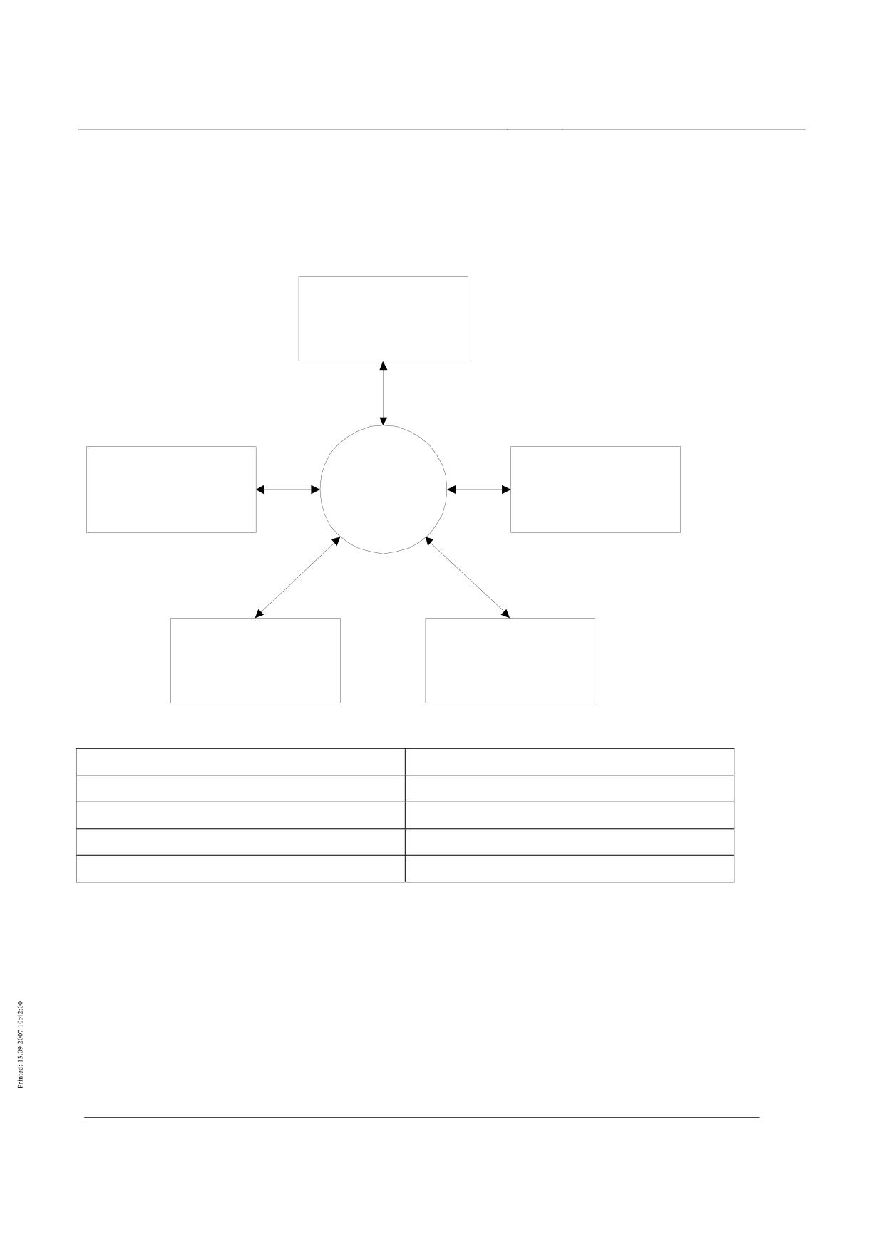
High-speed magnetic levitation railway
Maglev Technical Committee
Design principles
Operational control systems
Overview of the operational control system
This overview describes the usual organisation of the "operational control system" in a track-
guided railway system, as applied to the Transrapid type of high-speed Maglev system. Other struc-
tures or functional divisions are possible and are not intended to be excluded by this overview.
Fahrdienst -
leitung
Fahrweg,
BLT
Fahrzeug
Stationen
Antrieb
Instandhaltung
Figure 101: Organisation and interfaces of the operational control system
Fahrdienstleitung
Traffic controller
Fahrweg, Stationen
Guideway, stations
Fahrzeug
Vehicle
Antrieb
Propulsion system
Instandhaltung
Maintenance
The operational control system must include the components and functions for protecting, monitor-
ing and controlling operation.
This design principles does not apply to the infrastructure control system, which includes:
•
Building control system, e.g. to control the lighting or ventilation of buildings, stations, tun-
nels etc.
•
Engineering control rooms, e.g. for controlling and monitoring escalators or lifts
•
Passenger information equipment
•
Telecommunications equipment.
Title
High-speed Maglev system design principles
Operational control systems
Docu-
53328
Version White Pa-
Publication
15.02.2007
Page7
ment no.:
per
date
High-speed magnetic levitation railway
Maglev Technical Committee
Design principles
Operational control systems
The operational control system must connect the sections of the high-speed Maglev system to an
overall system that is ready for operation.
The adjacent sections and operative levels of the BLT are:
•
Traffic superintendents
•
Guideway and stations (including track change equipment and reference points for loca-
tion)
•
Vehicle (all technically protected vehicles)
•
Propulsion system and power supply (substations with propulsion units)
•
Maintenance.
The BLT includes the ability to control train traffic in automatic operation in accordance with a
prearranged timetable. The traffic superintendent must also be able to enter settings into the BLT
manually.
The components of the operational control system can be mobile, e.g. security computer for a vehi-
cle, or static, e.g. security computer for an area of guideway.
The fixed-location components can be further divided into central components of an operations
centre and decentralized components.
The central components are divided into areas for operation and display, the timetable system and
the diagnostic system and depending on the project these components can be brought together in a
common operator interface.
It must be configured at the planning stage in accordance with the operator's specifications.
Title
High-speed Maglev system design principles
Operational control systems
Docu-
53328
Version White Pa-
Publication
15.02.2007
Page8
ment no.:
per
date
High-speed magnetic levitation railway
Maglev Technical Committee
Design principles
Operational control systems
System requirements
The BLT must satisfy the requirements of /DIN EN 50126/, /DIN EN 50128/ and /DIN EN 50129/.
Characteristics of the safe state of the high-speed Maglev system are that every technically secured
vehicle does not exceed a location-dependent speed under all foreseeable fault and emergency situa-
tions within a technically secured section with defined hazard rates and does not overrun a defined
danger point and reaches a stopping place while levitating.
Characteristics of a fully technically secured system state are that the trips made are fully techni-
cally secured and that they are unsupervised.
The BLT must also enable release levels in addition to a fully technically secured system state.
An example of a release level can be an operating mode that requires the responsibility of person-
nel.
The following chapters describe the demands that this makes on the BLT.
Basic requirements
Operation must be controlled according to the requirements of an operating design that is to be
drawn up specifically for the project concerned.
The traffic superintendent must be able to allow trip settings to be executed automatically.
The traffic superintendent must be able to input manual settings to control operation.
Supervised operational manoeuvres, e.g. interventions by the traffic superintendent at safety level,
must be secured by operational and technical procedures.
The operational and technical procedures refer to operational regulations and technical process
protection.
When the BLT is responsible for safety during operation it must not leave its safe system condition
while personnel are performing control operations.
Operating errors by personnel in operations centres and trip personnel must have no effect on the
operability of the BLT.
E.g. if the traffic superintendent enters a wrong input this must not cause the BLT system to crash.
Operations that are not right for a given situation can have an adverse effect on operation. Super-
vised operations that do not comply with the rules can have an adverse effect on safety.
The reaction of the BLT to individual faults of a component must be error-tolerant but must not
cause normal operation to stop.
Overview of functions
Figure 102 gives an overview of the most important operational control functions and data flows.
BLT functions are shown in oval boxes and external components in rectangular boxes.
Title
High-speed Maglev system design principles
Operational control systems
Docu-
53328
Version White Pa-
Publication
15.02.2007
Page9
ment no.:
per
date
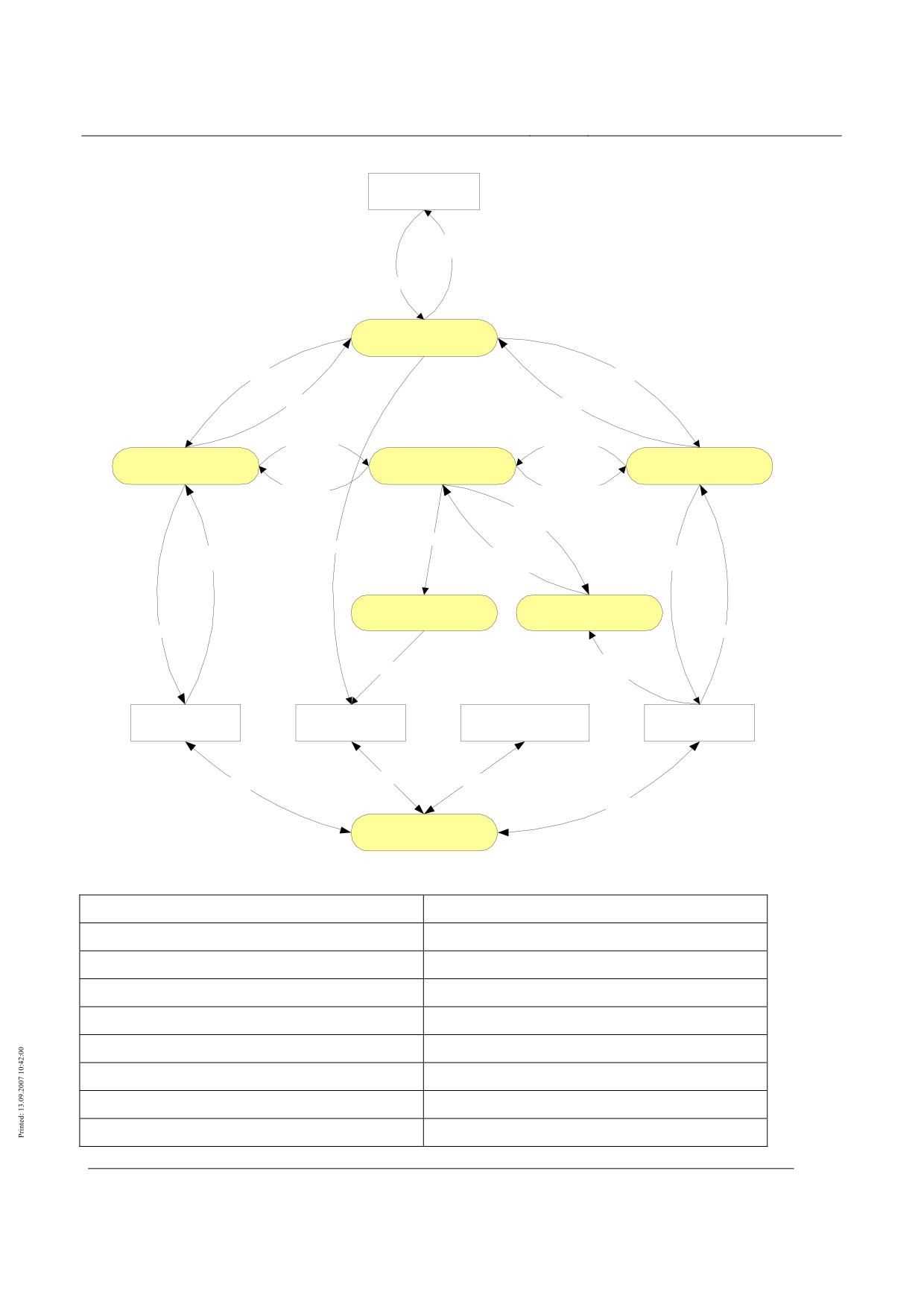
High-speed magnetic levitation railway
Maglev Technical Committee
Design principles
Operational control systems
Fahrdienstleitung
Meldungen,
Anzeigen
Fahrtvorgaben
Fahrablaufsteuerung
Fahrwegparameter
Fahrzeugparameter
Fahrweggdaten
Fahrzeugdaten
Fahrwegdaten
Fahrzeugdaten
Fahrprofil -
Fahrwegsicherung
Fahrzeugsicherung
überwachung
Fahrzeug-
Profilverletzung
bewegung
Ortungs-
parameter
Profilverletzung
Antriebsvorgaben
Lageinformation,
Ort,
Stellbefehle,
Meldungen
Geschwindigkeit
Ausgaben
Antriebsabschaltung
Sichere Ortung
Stellbefehle
Eingaben
Ort,
Abschaltbefehl
Geschindigkeit
Fahrweg ,
Antrieb
Instandhaltung
Fahrzeug
Stationen
Daten
Daten
Daten
Daten
Datenübertragung
Figure 102: Overview of BLT functions and data flows
Fahrdienstleitung
Traffic controller
Meldungen, anzeigen
Messages, displays
Fahrtvorgaben
Trip settings
Fahrablaufsteurerung
Trip progress control
Fahrwegparameter
Guideway parameters
Fahrzeugparameter
Vehicle parameters
Fahrwegdaten
Guideway data
Fahrzeugdaten
Vehicle data
Fahrwegsicherung
Guideway protection
Title
High-speed Maglev system design principles
Operational control systems
Docu-
53328
Version White Pa-
Publication
15.02.2007
Page10
ment no.:
per
date
High-speed magnetic levitation railway
Maglev Technical Committee
Design principles
Operational control systems
Fahrprofilüberwachung
Driving profile monitoring
Fahrzeugsicherung
Vehicle protection
Fahrzeugbewegung
Vehicle movement
Profilverletzung
Profile violation
Ortungsparameter
Location parameters
Lageinformationen, Meldungen
Position information, messages
Antriebsvorgaben
Propulsion system settings
Ort, Geschwindigkeit
Location, speed
Stellbefehle, Ausgaben
Actuator commands and output
Antriebsabschaltung
Propulsion system shutdown
Sichere Ortung
Safe location
Stellbefehle
Actuator commands
Eingaben
Inputs
Abschaltbefehl
Shutdown command
Ort, Geschwindigkeit
Location, speed
Fahrweg, Stationen
Guideway, stations
Antrieb
Propulsion system
Instandhaltung
Maintenance
Fahrzeug
Vehicle
Daten
Data
Datenübertragung
Data transmission
Functional requirements
According to /DIN EN 50126/ the operator is responsible for determining the safety requirements
for the functions of the high-speed Maglev system in a risk analysis and assigning the results to the
BLT functions.
Depending on the risks arising in the event or an operational failure, the functions of the BLT are
divided into safety-relevant and non-safety relevant functions. The division must be done within the
framework of the project-specific risk analysis that has been drawn up and the safety requirements
for the various functions.
The safety-relevant functions of the BLT usually include vehicle protection, guideway protection,
safe location, driving profile monitoring and safe shutdown of the propulsion system.
If safety-relevant functions fail, the safe system state must be maintained.
The probability of a function failing to the hazardous side must be made sufficiently low in accor-
dance with the project-specific safety requirements that have been determined.
The safety-relevant functions must be implemented and certified in accordance with the correspond-
ing specific safety requirements.
It must be possible to remove the safety-relevant functions of the BLT in a sequence of steps that
build on each other.
Title
High-speed Maglev system design principles
Operational control systems
Docu-
53328
Version White Pa-
Publication
15.02.2007
Page11
ment no.:
per
date
High-speed magnetic levitation railway
Maglev Technical Committee
Design principles
Operational control systems
Control of trip progress
Safe operation and display
The safety-relevant operations are supported by error-free status displays of the process during
operation.
The status of mobile plant and equipment in guideway areas in which technically protected trips
take place must be displayed by the safety and security system. This includes, for example:
•
Track change equipment
•
Platform doors
Areas (e.g. maintenance plant) in which fully protected trips do not take place can be project-
specifically defined.
Sections of the guideway that are occupied by or reserved for a vehicle must be displayed by the
safety and security system.
If the propulsion system is switched off this state must be displayed to the traffic superintendent.
For supervised operations, a safe procedure command input must be provided, e.g. to release locked
sections of the guideway or for the use of vehicles.
Generation of trip settings
An operation schedule must be drawn up for each project and must contain the relevant data for
automatic operation. The timetable settings will be derived from the operation schedule.
It must be possible to generate timetables automatically on the basis of timetable settings.
It must also be possible to draw timetables up manually.
Timetables must be available in a form that can be used as input data for automatic operation.
Timetables must be drawn up in such a way that an operation can be carried out as far as possible
without stopping at operational stopping points.
The following data, for example, may be relevant in a timetable: Line number, trip number, destina-
tion, departure point and departure time.
It must be possible to generate trip settings for Maglev vehicles and the guideway automatically
from the timetables.
It must also be possible to enter trip settings manually in the operations centre.
Alternatively, trip settings for the Maglev vehicle must be able to be entered manually in the vehi-
cle.
These can be trip settings such as speed and direction of travel.
The BLT must be able to log actual trip details.
The logged trip details can be converted to timetables.
External interface:
Propulsion system settings must be transmitted to the propulsion system.
Propulsion trip settings include details of the reserved guideway, driving profile and limiting values
for the trip.
It must be possible to generate and transmit other control data for the activation or deactivation of
propulsion system functions, e.g. release commands and powering up or down, for specific projects.
Failure behaviour and the effect of failure
In the event of failure of the automatically generated trip settings, it must also be possible to enter
manual trip settings in the operations centre.
Title
High-speed Maglev system design principles
Operational control systems
Docu-
53328
Version White Pa-
Publication
15.02.2007
Page12
ment no.:
per
date
High-speed magnetic levitation railway
Maglev Technical Committee
Design principles
Operational control systems
If the automatically generated trip settings fail, the traffic superintendent may not be able to main-
tain operation according to the timetable, as all the trip settings will need to be entered by hand
and this will be time-consuming.
Guideway setting
It must be possible for an operator to enter a changeover command for individual movable elements
of the guideway.
It should be possible to set all the movable elements of the guideway for a predetermined combina-
tion of departure point and destination.
The implementation of guideway reservation requests and guideway settings from predetermined
combinations of departure point and destination must take guideway safety requirements into ac-
count.
Failure behaviour and the effect of failure
If changeover commands for individual movable elements of the guideway are no longer possible
the movable elements of the guideway can no longer be controlled remotely.
If changeover commands for individual movable elements of the guideway are no longer possible
trips must still be able to take place on the guideway as it is set.
If the setting for a combination of departure point and destination is no longer possible, the guide-
way can no longer be set remotely.
If the setting for a combination of departure point and destination is no longer possible, it must still
be possible to send changeover commands for individual movable elements of the guideway.
Generation and transmission of control data for the vehicle
Other control data for the activation or deactivation of vehicle system functions, e.g. air condition-
ing system, vehicle headlamps, internal lighting, can be generated and transmitted for specific pro-
jects.
Control data must be able to be generated automatically, depending on location or time.
It must also be possible to input control data manually.
It must be possible to transmit control data from the operations centre to the vehicle.
Failure behaviour and the effect of failure
Interruption during transmission of control data must not lead to malfunctions of the BLT.
A control data transmission failure must not lead to a direct safety reaction by the BLT.
Automatic operation
Automatic operation means that there is no need for any operations by personnel in order for a trip
to take place. The traffic superintendent starts a defined program for trips and this is available as a
timetable. The timetable will then run automatically.
The automatic control of trips is based on timetables that must be able to be stored in the BLT and
then called up again.
The trip settings generated for the Maglev vehicles and the guideway from the timetables must run
automatically without any manual operations.
This also includes, for example, triggering of the reservation of guideways, (chapter 0) and the set-
ting of points (chapter )0).
The automatic control of trips must be independent of the technical protection system and free of
reactions from it.
Title
High-speed Maglev system design principles
Operational control systems
Docu-
53328
Version White Pa-
Publication
15.02.2007
Page13
ment no.:
per
date
High-speed magnetic levitation railway
Maglev Technical Committee
Design principles
Operational control systems
In automatic operation, the execution of trip settings must take into account the conditions of full
technical protection.
In automatic operation only control operations, i.e. unsupervised operations, are permitted to be
executed automatically.
In automatic operation it must be possible for the traffic superintendent to carry out manual opera-
tions.
Automatic mode must be designed in such a way that the Maglev vehicles depart on time in fault-
free operation.
Deviations from the timetable, e.g. delays, must be automatically detected and displayed.
In the event of deviations from the timetable the planned schedule must be reinstated automatically.
This can be achieved, for example, by shortening standing times. The measures needed or permissi-
ble to achieve this are subject to project-specific definition.
Protection of the guideway
The guideway protection system must include all the guideways on which trips are to take place
under the responsibility of technical safety.
These can be guideways in free sections, stations, stabling locations and maintenance locations.
Data on guideway protection must be prepared for the operations centre.
Guideway protection status messages are displayed in the operations centre.
Stationary equipment that violates the structure gauge must be included in the guideway protection
system.
Stationary equipment within this definition may include shed doors and washing installations.
Project-specific exceptions are permissible for supervised trips.
Failure behaviour and the effect of failure
If the guideway protection system fails completely a forced stop at a stopping place must be exe-
cuted.
Reservation of guideways
A guideway must be reserved so that a trip can take place.
Reservation of a guideway for a trip consists in setting the movable elements of the guideway, tech-
nically protecting the guideway to be travelled over without gaps and completely, and assigning this
guideway exclusively to a vehicle.
Only the vehicle to which this reservation is assigned is allowed onto the reserved guideway.
Sections of reserved guideways must not be reserved for other trips.
This ensures that no other technically protected vehicle can enter a reserved guideway.
The BLT must ensure that a technically protected vehicle does not leave the guideway that has been
reserved for it.
It must not be possible for track change equipment in reserved sections of guideway to be reposi-
tioned.
This applies to the repositioning of track change equipment either technically via the system or via
manual intervention.
Occupation of guideways
The BLT must display a section of guideway as occupied and treat it as such when a technically
protected vehicle is in this section.
A section of guideway must only be displayed and treated as no longer occupied when the techni-
cally protected vehicle has completely left it.
Title
High-speed Maglev system design principles
Operational control systems
Docu-
53328
Version White Pa-
Publication
15.02.2007
Page14
ment no.:
per
date
High-speed magnetic levitation railway
Maglev Technical Committee
Design principles
Operational control systems
Sections of guideway that are occupied by a vehicle must only be included in a guideway reserva-
tion for this technically protected vehicle.
Control operations must not cause this occupation status to change.
Cancelling the reservation of guideways
After the technically protected vehicle has completely left a reserved section of guideway, reserva-
tion for this section must be automatically cancelled.
This requirement can be a project-specific condition for automatic operation.
In a climb where the kinetic energy of the vehicle is not sufficient for the next stopping place in the
direction of travel to be reached, the guideway as far as the next stopping place behind the vehicle
(including this stopping place) must remain reserved until the next stopping place in the direction of
travel can be reached using the kinetic energy of the vehicle.
It must also be possible to cancel guideway reservations manually.
It should also be possible to use automatic trip settings to cancel guideway reservations (chapter 0).
Guideway reservations may be cancelled when there is no vehicle in the reserved guideway.
Guideway reservations may be cancelled when the vehicle in the reserved guideway is at a safe
standstill.
Guideway reservations may be cancelled if this reserved guideway is not needed to reach a stopping
point.
Blocking of guideways
It must be possible to block guideway sections manually.
Guideway reservations over blocked sections must only be done with supervision.
It must not be possible to block a guideway in a reserved guideway section.
This is to avoid, e.g. a blocked guideway causing a vehicle to stop outside a stopping place.
Failure behaviour and the effect of failure
After the failure and restoration of the guideway protection system the guideway blocking should be
restored automatically.
This automatic restoration can be a project-specific requirement, depending on the risk analysis or
the complexity of the installation.
If the guideway blocking is not automatically restored after a failure of the guideway protection
system, the traffic superintendent must be shown that supervised restoration of guideway blockings
is needed.
Release of guideway blocks
Manual guideway blocks must be released under supervision.
Manually blocked guideway sections must only be released one at a time.
Protection of track switching equipment
In general, a distinction is made between track switching equipment that does not require interrup-
tion of the trip (points) and track switching equipment that may require the trip to be interrupted
(slewing platforms and sliding platforms).
A track switching device in a secured end position must have reached an end position, be locked
and protected against readjustment.
The track switching equipment must only be included in guideway reservations when it is in its se-
cured end position.
Title
High-speed Maglev system design principles
Operational control systems
Docu-
53328
Version White Pa-
Publication
15.02.2007
Page15
ment no.:
per
date
High-speed magnetic levitation railway
Maglev Technical Committee
Design principles
Operational control systems
Vehicles must only be allowed to run over the track switching equipment when it is in its secured
end position.
It must not be possible to readjust a track switching device in a reserved guideway section.
It must not be possible to readjust switching points when they have a vehicle on them.
Adjustment of a sliding or slewing platform with a vehicle on it is only permissible when the whole
of the vehicle is on the sliding or slewing platform and is at a safe standstill.
It must be possible to issue a manual release to the local track switching equipment operator.
Release of local manual operation must only be possible when the track switching equipment is not
included in a guideway reservation.
After release of local manual operation the track switching equipment must not be included in a
guideway reservation.
It must be possible to lock track switching equipment manually to prevent readjustment.
Track switching equipment that has been locked to prevent readjustment must only be released un-
der supervision.
Failure behaviour and the effect of failure
Failure of the protection function must not lead to release of the adjustment process.
The design of the track switching equipment must ensure that it is not possible for it to leave the
secured end position by itself unless it has been released via the protection equipment.
If a safe end position has been reached after an adjustment process and no further release for ad-
justment has been issued, it should be possible to run vehicles over the track switching device even
after failure of the end position feedback or the protection equipment.
After the safe end position has been reached the track switching equipment must remain in this po-
sition independently of failures of the control, monitoring or power supply systems.
If track switching devices are blocked to prevent readjustment, it should be possible to restore the
block automatically after the failure and restoration of the track change switching device protection.
This automatic restoration can be a project-specific requirement, depending on the risk analysis or
the complexity of the installation.
If this blocking is not automatically restored after a failure of the protection system, the traffic su-
perintendent must be shown that supervised restoration of the blocking is needed.
Protection of the platform door system
Platform doors in a secured end position must be closed, locked and protected against opening.
Vehicles must only be allowed to run into a guideway section with platform doors when all the
doors are in the secured end position.
The operational control system must only release platform doors for opening when the Maglev ve-
hicle is opposite the platform doors and safely stopped.
A platform door must only be allowed to open automatically when the platform door is opposite a
vehicle door and the gap between the two doors is as small as possible.
Vehicles must only be allowed to levitate and depart when all the platform doors are in the secured
end position.
Project-specific local operation of platform doors may be provided for door and/or station mainte-
nance purposes.
If local operation of platform doors is provided in a specific project, it must be possible for the local
operation of platform doors to be enabled manually.
Release of local manual operation must only be possible when the guideway with the platform
doors is not included in a guideway reservation.
Title
High-speed Maglev system design principles
Operational control systems
Docu-
53328
Version White Pa-
Publication
15.02.2007
Page16
ment no.:
per
date
High-speed magnetic levitation railway
Maglev Technical Committee
Design principles
Operational control systems
After release of local manual operation the guideway with the platform doors must not be included
in a guideway reservation.
Where other entrances or exits are provided in addition to the platform doors, project-specific re-
quirements may be defined, e.g. depending on the risk analysis.
Failure behaviour and the effect of failure
Failure of the protection function must not lead to release of the opening process.
The design of the platform doors ensures that it is not possible for them to leave the secured end
position independently unless they has been released via the protection equipment.
The BLT must show an alert in the event of failure of the safe end position report.
If the safe end position report for a platform door fails to arrive, a project-specific engineering re-
action must take place. This can take the operating situation into account, e.g. arrival, departure or
stop.
Local manual locking of platform doors with defective control or feedback must be possible (with
supervision, apart from the BLT).
This will bypass the control and monitoring functions for the door concerned.
Vehicle protection systems
Vehicle protection systems must monitor and control the safety-relevant functions and conditions of
Maglev vehicles that are described below.
They must therefore handle e.g. levitation, setting down, monitoring on-board energy and control of
the safe brake via the vehicle control system.
It may be necessary to have a project-specific subset of these functions and conditions for other
technically protected vehicles.
Monitoring the redundancy of safety-relevant vehicle functions
The vehicle section reports to the BLT that no failures or losses of redundancy of safety-relevant
vehicle functions such as levitation/guidance, safe brake and on-board energy supply are present.
The BLT must continuously monitor the reports from the vehicle section concerning the failure-free
state and complete redundancy of the safety-relevant vehicle functions.
The safety-relevant vehicle functions themselves are checked by the vehicle section without being
initiated by the BLT.
The BLT must trigger a safety-related reaction if the report is cancelled.
The safety-related reaction should be in stages and run one step at a time.
A possible sequence for the multi-stage safety-related reaction is given below.
1. Forced stop at a service station (continued trip via operational stopping places and stations)
2. Inhibition (continued trip via operational stopping places)
3. Forced stop at the current stopping place (trip not continued)####
The stages and sequence of the safety-related reaction by the BLT are subject to project-specific
definition.
The actual sequences and times must be defined at the interface between the BLT and the vehicle
section.
Failure behaviour and the effect of failure
If the failure or loss of redundancy is reported on powering up the vehicle, the BLT must react im-
mediately by inhibiting the Maglev vehicle concerned.
The most severe consequence of a complete loss of redundancy monitoring of vehicle functions is a
forced stop at the current stopping place.
Title
High-speed Maglev system design principles
Operational control systems
Docu-
53328
Version White Pa-
Publication
15.02.2007
Page17
ment no.:
per
date
High-speed magnetic levitation railway
Maglev Technical Committee
Design principles
Operational control systems
Control and supervision of brake testing
The following requirements only apply if the technically protected vehicles are fitted with an active
safe braking system, e.g. eddy current braking circuits.
The BLT must monitor that functional testing of defined components of the safe braking system is
initiated at fixed intervals (brake test).
The BLT must ensure that the brakes are not tested during a trip.
The BLT must ensure that the brakes are tested between powering up the vehicle and the end of the
failure disclosure time.
If the brake check is not initiated between powering up the vehicle and the end of the failure disclo-
sure time a safety-related reaction must be started.
The safety-related reaction should be executed in stages before the end of the failure disclosure
time.
The BLT must ensure that the vehicle only levitates and departs after the brakes have been tested
and confirmed OK.
It must be possible to initiate the brake check manually.
This is necessary, for example, after maintenance work on the safe brake components.
It should also be possible to initiate the brake check automatically from the timetable.
To maintain operational availability the brake test should be performed in due time before the ex-
piry of the failure disclosure time.
Control and supervision of the on-board energy supply
Charge status of the on-board energy supply
The vehicle section must send a report to the BLT that the charge needed to complete a trip, includ-
ing a stop with the safe brake, is guaranteed.
The BLT must monitor the reported charging status of the on-board energy supply of the Maglev
vehicle.
This ensures that safety-relevant functions such as levitation and the safe brake can be executed
according to specification.
The BLT must trigger a safety-related reaction if the report is cancelled.
Depending on the design of the on-board energy supply, a project-specific definition is required to
state whether this safety-related reaction should be a forced stop or an immediate stop.
The BLT must ensure that the vehicle does not levitate and depart if the brakes have not been con-
firmed OK.
Loss of redundancy in the on-board energy supply
If the on-board energy supply loses redundancy the vehicle section sends a report to the BLT.
The BLT must monitor the reported redundancy status of the on-board energy supply of the Maglev
vehicle.
The on-board energy supply must guarantee the levitation and safe braking of a vehicle after depar-
ture and as far as the next stop.
The BLT must report loss of redundancy to ensure that a stopped vehicle does not levitate and de-
part.
Title
High-speed Maglev system design principles
Operational control systems
Docu-
53328
Version White Pa-
Publication
15.02.2007
Page18
ment no.:
per
date
High-speed magnetic levitation railway
Maglev Technical Committee
Design principles
Operational control systems
External on-board energy supply
Depending on the specific project, components of the Maglev vehicle for the external on-board en-
ergy supply must be included in the control and monitoring done by the BLT.
Where current collectors are used, a safety-relevant enable signal, for example, must be produced
for the current collectors.
Failure behaviour and the effect of failure
In the event of loss of the control and monitoring functions of the on-board energy supply, or the
loss of parts of these functions, the BLT must react when the Maglev vehicle is set down by inhibit-
ing the vehicle concerned.
Loss of the control and monitoring functions of the on-board energy supply, or loss of parts of these
functions during operation must lead to a forced stop at the current stopping place.
The on-board energy supply must guarantee the levitation and safe braking of a vehicle after depar-
ture and as far as the next stop.
Control and supervision of safe braking
The vehicle must be fitted with a safe brake. This enables it to be stopped safely in the event of pro-
pulsion system faults or certain BLT faults.
The safe brake must be controlled and monitored by the BLT.
Whenever the vehicle comes to a forced stop with the safe brake, the propulsion system must be
switched off before the braking command is issued.
Depending on the location, it must be possible for the safe brake and the propulsion system to be
effective simultaneously under exceptional circumstances.
The locations concerned are subject to project-specific definition.
These exceptional circumstances are allowed, if for example the guideway loads, vehicle loads and
prescribed acceleration values are not exceeded.
The vehicle section monitors the brake circuits of the Maglev vehicle and transmits a report to the
BLT that sufficient operation of the brake circuits is guaranteed.
The BLT must trigger a forced stop at the next service station if this report is cancelled.
Failure behaviour and the effect of failure
If the "Control and supervision of safe braking" function fails, maximum control of the safe brake
must be used.
This leads to an uncontrolled stop of the vehicle without approaching a stopping place.
In the event of the complete failure of the location system or certain combinations of failures (mul-
tiple failures) of the BLT hardware maximum control of the safe brake is used and this can lead to a
momentary superimposition of the traction or braking forces of the propulsion system and the safe
brake.
The probability of occurrence and the maximum duration of superimposition of the braking forces
of the propulsion system and the safe brake are subject to project-specific definition.
This superimposition must be regarded as a special load when designing the guideway and the ve-
hicle, depending on the probability of its occurrence and the maximum duration.
Failures of redundancy must not cause untimely switching on or off of the safe brake.
Protection of the outer doors of the vehicle
Vehicle outer doors in a secured end position must be closed, locked and protected against opening.
Vehicles must only be allowed to levitate and depart when all the vehicle doors are in the secured
end position.
Title
High-speed Maglev system design principles
Operational control systems
Docu-
53328
Version White Pa-
Publication
15.02.2007
Page19
ment no.:
per
date
High-speed magnetic levitation railway
Maglev Technical Committee
Design principles
Operational control systems
The operational control system must only release vehicle doors for opening when the Maglev vehi-
cle is safely stopped.
This door release must only be triggered at designed locations for the sides that are permitted there.
The door release must be able to be triggered automatically or manually by the traffic superinten-
dent.
The safe end position status of the outer vehicle doors must be transmitted to the operations centre.
Failure behaviour and the effect of failure
Failure of the protection function for outer vehicle doors must lead to the BLT assuming that the
doors are not locked and the BLT must react by inhibiting the Maglev vehicle concerned.
Failure of the protection function must not lead to release of the opening process.
The design of the vehicle outer doors ensures that it is not possible for them to leave the secured
end position independently unless they has been released via the protection equipment.
The BLT must show an alert in the event of failure of the safe end position report.
If the safe end position report for a vehicle outer door fails to arrive, a project-specific engineering
reaction must take place. This can take the operating situation into account, e.g. moving or stopped.
Manual local locking of doors with defective control or feedback must be possible (with supervi-
sion, apart from the BLT).
This will bypass the control and monitoring functions for the door concerned.
Control and supervision of levitation
The levitation control and monitoring function is the operational control part of the levitation func-
tion.
The BLT must control and monitor the levitation and setting down of the Maglev vehicle.
The BLT must ensure that the release for levitation of the Maglev vehicle can only be issued if all
the safety-related requirements for travel are met and the departure order has been given.
The safety-related requirements for travel include, e.g. locking of the outer doors of the vehicle.
Other project-specific safety-related requirements can be defined.
The BLT must ensure that the release for levitation of the Maglev vehicle can only be cancelled if
all the safety-related requirements for setting down are met.
The safety-related requirements for setting down include, e.g. that the vehicle speed is lower than a
setting-down speed that has been defined for the BLT. Other project-specific safety-related re-
quirements for setting down can be defined.
Control-related requirements should also be met before the release for levitation can be cancelled.
The control-related requirements for setting down include e.g. a report from the propulsion system
that the trip is completed.
After the release has been given for levitation of the Maglev vehicle by the BLT, the vehicle's levi-
tation function must continue to be monitored until the next time it is set down.
So long as the BLT receives reports that the vehicle function levitation can no longer be main-
tained, the BLT must initiate a forced stop at the next service station. If no stopping place identified
as a service station is reached within a time subject to project-specific definition, a forced stop must
be automatically initiated.
This requires that until the forced stop at a service station is completed the vehicle levitation func-
tion is maintained.
Maglev vehicles must be set down while passengers board and leave the train.
Failure behaviour and the effect of failure
Title
High-speed Maglev system design principles
Operational control systems
Docu-
53328
Version White Pa-
Publication
15.02.2007
Page20
ment no.:
per
date
High-speed magnetic levitation railway
Maglev Technical Committee
Design principles
Operational control systems
Complete loss of the levitation control function must lead to cancellation of the levitation release
command.
Setting the vehicle down must then be the responsibility of the vehicle levitation function.
Forced stop
Forced stops are automatically generated by the BLT functions.
It must be possible to trigger forced stops manually.
It must be possible for personnel in the operations centre and in the Maglev vehicle to trigger a
manual forced stop.
Specific projects may specify manual forced stops at other places, e.g. stations.
Manual forced stops can be executed as a forced stop at the current stopping place or as an imme-
diate stop.
Automatic forced stops can be executed as a forced stop at a service station or a forced stop at the
current stopping place or as an immediate stop.
The forced stop at the current stopping place can also be executed as a reversible forced stop.
Project-specific definition is required as to whether after cancellation of a manual forced stop, while
the Maglev vehicle is at a standstill, it is permitted for it to start again immediately or whether this
must be initiated by restating the trip settings.
Failure behaviour and the effect of failure
Faults in the forced stop function must lead to a safety-related reaction.
Monitoring of the driving profile
The BLT must monitor the vehicle speed, which must be within a permitted speed range.
The permitted speed range is between the maximum driving profile corresponding to the locally
permissible maximum speed and the minimum driving profile corresponding to the local minimum
speed for reaching the current stopping place.
The BLT must calculate the permitted speed range taking into consideration the current operating
situation, e.g. from the position of points and low speed areas.
Monitoring of the maximum driving profile
The BLT must ensure that hazard points are not exceeded and the driving profile limit is observed.
Every hazard point must therefore have a local maximum driving profile defined for it in the BLT.
To determine the maximum driving profile, the BLT must take into account relevant system pa-
rameters such as reaction times, the safe brake characteristic and the route.
If the maximum driving profile is violated the propulsion system must be safely shut down and a
reversible forced stop to the current stopping place using the safe brake must be triggered.
The forced braking may only be cancelled when the maximum driving profile is no longer ex-
ceeded.
Failure behaviour and the effect of failure
Faults in the maximum driving profile monitoring system must lead to a forced stop.
If the maximum driving profile monitoring system fails completely an immediate stop must be exe-
cuted.
Monitoring of the minimum driving profile
The BLT must ensure that the Maglev vehicle can also reach the current stopping place without the
propulsion system.
Every stopping place must therefore have a local minimum driving profile defined for it in the BLT.
Title
High-speed Maglev system design principles
Operational control systems
Docu-
53328
Version White Pa-
Publication
15.02.2007
Page21
ment no.:
per
date
High-speed magnetic levitation railway
Maglev Technical Committee
Design principles
Operational control systems
To determine the minimum driving profile, the BLT must take into account relevant system pa-
rameters such as the safe levitation profile, reaction times and the route.
If the minimum profile is violated the BLT must actuate a safe shutdown of the propulsion system
braking forces.
The safe brake can be used to stop the Maglev vehicle when it arrives at the stopping place.
The BLT must ensure that the Maglev vehicle is set down when the stopping place is reached.
The propulsion system shutdown command may only be cancelled when the minimum driving pro-
file is reached again.
After starting out from a station it is not immediately possible to monitor the minimum driving pro-
file. Project-specific provision should be made for evacuation facilities and an external on-board
energy supply to cover the starting out areas in operational use.
The minimum driving profile monitoring system must be automatically activated when the mini-
mum driving profile of the stopping place following the starting out area is exceeded.
It must be possible to switch off the monitoring of the minimum driving profile manually.
It is necessary to switch monitoring of the minimum driving profile off if, for example, travel at less
than the minimum speed is necessary for operational reasons.
Safe propulsion system shutdown
The propulsion system in the high-speed Maglev system converts both traction energy and braking
energy.
The propulsion system and power supply section must be equipped with devices for shutting down
the propulsion system safely so that the flows of both traction energy and braking energy can be
safely stopped.
The BLT must trigger the safe shutdown of the propulsion energy flow:
•
If the maximum or minimum driving profile (chapter 0) is violated
•
Before a forced braking manoeuvre with the safe brake (chapter 0)
•
If the transmission of safety data (chapter 0) fails
•
In the event of an immediate stop.
Depending on the reason for the shutdown, the propulsion energy in the section to be switched off
must be reliably switched off within a defined time after the reason for switching off has arisen.
If there is a reason to switch off and a Maglev vehicle
•
is in more than one propulsion area, e.g. during a change of propulsion, or
•
is in a propulsion area that more than one converter can supply,
it must be ensured that no converter can supply current in these areas.
The safe shutdown of the propulsion system can be reversible or non-reversible.
If the propulsion system shutdown is reversible and the reason for shutting down is no longer pre-
sent, the BLT must automatically re-enable the propulsion system.
Reasons for switching off reversible propulsion system shutdowns include forced braking when the
driving profile is violated and the temporary failure of the transmission of safety data.
The BLT must not automatically re-enable the propulsion system after irreversible propulsion sys-
tem shutdowns.
The propulsion system shuts down irreversibly on an immediate stop, e.g. after a complete failure of
the safe location function (chapter Error! Reference source not found.) or the complete failure of
maximum driving profile monitoring )chapter 0)
Title
High-speed Maglev system design principles
Operational control systems
Docu-
53328
Version White Pa-
Publication
15.02.2007
Page22
ment no.:
per
date
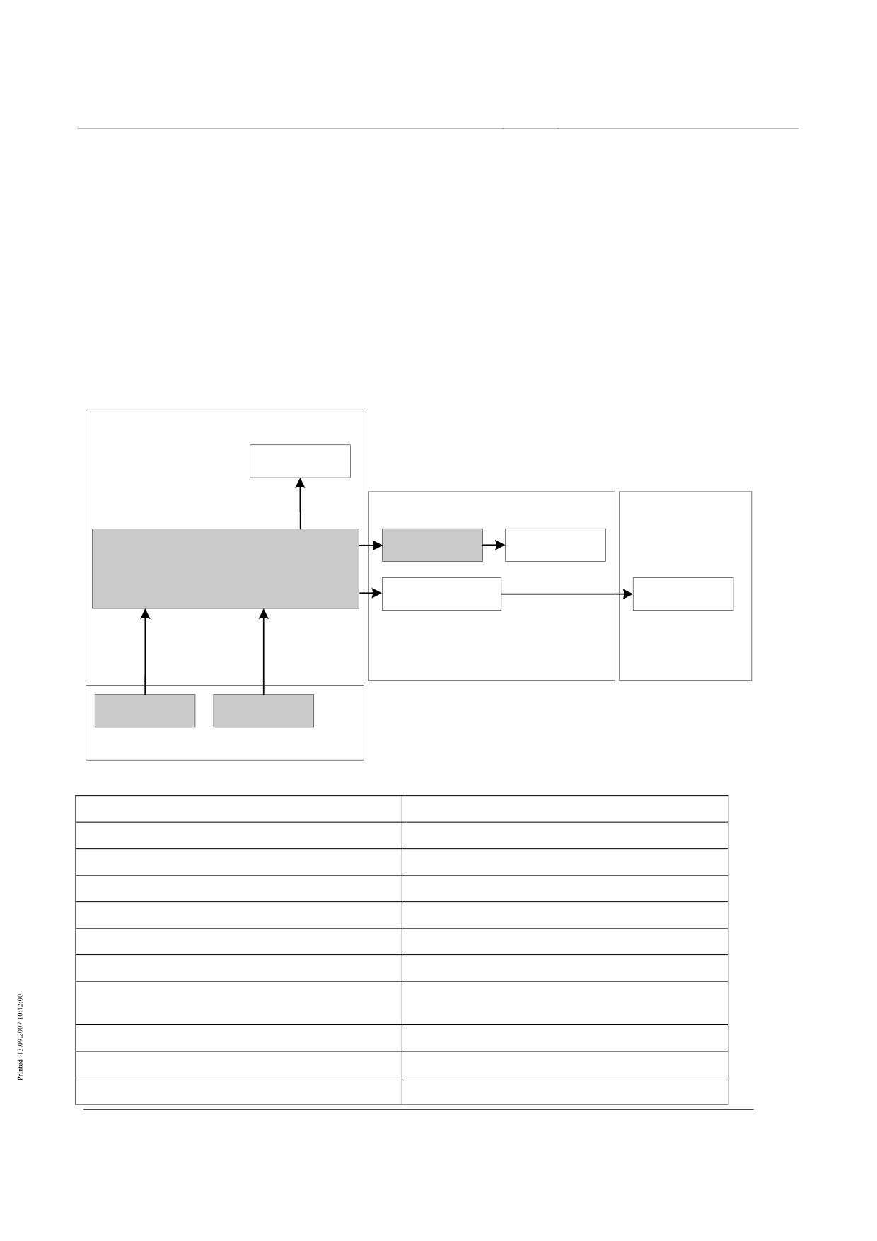
High-speed magnetic levitation railway
Maglev Technical Committee
Design principles
Operational control systems
After irreversible propulsion system shutdowns the traffic superintendent must re-enable the pro-
pulsion system manually.
Failure behaviour and the effect of failure
If the safe propulsion system shutdown fails completely the shutdown of the propulsion energy flow
must be actuated.
How this is to be done must be defined at the interface between the BLT and the propulsion system.
If the safe propulsion system shutdown function fails completely during the braking procedure of
the propulsion system, the vehicle may possibly stop before the current stopping place but within
the reserved section.
Safe location
In accordance with /MSB AG-GESAMTSYS/ safe location consists of the safe location components
of the BLT and their interfaces with the control-relevant localization and BLT functions.
Fahrzeug
Anzeige
Betriebsleittechnik
Antrieb
BLT-
Sichere Ortung
Funktionen
Steuerungstechnisch
relevante Ortung
Datenübertragung
Antriebs-
Mobil-Ortsfest
regelung
Referenzorte
Relativort
Fahrweg
Figure 103: Structure of the location system
Fahrzeug
Vehicle
Anzeige
Display
Betriebsleittechnik
Operational control system (BLT)
Antrieb
Propulsion system
Sichere Ortung
Safe location
BLT-functionen
BLT functions
Steuerungstechnisch relevante Ortung
Location that is relevant to the controls
Datenübertragung Mobil-Ortsfest
Transmission of data between mobile and fixed
locations
Antriebsregelung
Regulation of propulsion system
Referenzorte
Reference locations
Relativort
Relative location
Title
High-speed Maglev system design principles
Operational control systems
Docu-
53328
Version White Pa-
Publication
15.02.2007
Page23
ment no.:
per
date
High-speed magnetic levitation railway
Maglev Technical Committee
Design principles
Operational control systems
Fahrweg
Guideway
In order for a trip to take place under complete technical protection the location, speed and direction
of travel of every vehicle must be known to the safety-related BLT at all times (safe location).
The safe location includes the availability of reliable data on location, speed and direction of
travel.
After a setting trip has been successfully completed the data on location, speed and direction of
travel is deemed to be reliable.
The location data supplied from the control-relevant location equipment is checked by the BLT, e.g.
by plausibility checking, mirroring against preset data and comparison with the individual items of
location data.
Certain malfunctions, e.g. detection of direction of travel, can only be detected during travel.
After the Maglev vehicle has been equipped, after a failure of the safe location function or when the
standstill time has exceeded the failure reporting time, a setting journey must be undertaken.
The permissible tolerances for location data must be defined on the basis of the specific properties
of the location procedure selected and the project-specific extensions.
The permissible tolerances for vehicle speed must be defined on the basis of the specific properties
of the location procedure selected and the project-specific extensions.
The permissible tolerances for detection of the direction of travel must be defined on the basis of
the specific properties of the location procedure selected and the project-specific extensions.
The tolerances of every location procedure have physical limits. These depend on the structure and
the selected location procedure. The tolerances affect the system layout and other system functions,
e.g. stopping accuracy. The requirements for them are taken into account when selecting the loca-
tion procedure.
If the safe location system fails completely the existing guideway reservation for this vehicle must
be maintained.
A guideway reservation for this vehicle may only be cancelled after a complete failure of the safe
location function when a safe location for this vehicle is known once again.
A safe location can also become known if it is reported under supervision and entered by means of
a supervised operation.
Failure behaviour and the effect of failure
Loss of redundancy in the safe location function or its sections must lead, at its most severe, to a
forced stop.
If the safe location system fails completely the BLT must execute an immediate stop.
Data transmission
Data transmission between the components of the BLT is identified by the volume of data, repetition
rate, availability, bit error rate and the division into safety-relevant and non-safety-relevant trans-
mission.
Data transmission takes place
•
between fixed and fixed, and
•
between fixed and mobile
components of the BLT.
The requirements for data transmission are subject to project-specific definition.
Project-specific definitions include the number of vehicles to be looked after at any one time.
Title
High-speed Maglev system design principles
Operational control systems
Docu-
53328
Version White Pa-
Publication
15.02.2007
Page24
ment no.:
per
date
High-speed magnetic levitation railway
Maglev Technical Committee
Design principles
Operational control systems
Transmission of safety data
Suitable transmission procedures for safety-relevant communication in closed or open transmission
systems must be laid down on the basis of the requirements for the transmission of safety-relevant
data.
Project-specific definitions are required for every data transmission, whether the system is an open
one or a closed one as described in /DIN EN 50159/.
This definition will give rise to various different requirements for the safety measures implemented
in the transmission system.
When safety-relevant data is being transmitted corrupted data (mutilated sender identity, type error,
mutilated value) and time errors (data delay too long, sequence errors) must be reliably detected.
This is the minimum requirement.
Where safety-relevant data and non-safety-relevant data are transmitted together, the absence of
interaction with the safety-relevant data must be guaranteed.
Since the transmission of safety-relevant data has precedence, there may be restrictions on the
transmission of non-safety-relevant data.
The unsecured data transmission of the BLT should be open for use by other sections.
Project-specific use can be made of the BLT transmission function, e.g. to transmit passenger in-
formation data and communication data between the operations centre and the Maglev vehicle.
Since the transmission of data to and from the BLT components that is necessary for operation has
precedence, there may restrictions on use by other sections.
Failure behaviour and the effect of failure
In the event of failure of the fixed-mobile transmission of safety-relevant data while the vehicle is
moving a safe propulsion shutdown must take place.
If, additionally, a profile violation occurs, a reversible forced braking procedure to the current stop-
ping place must take place as described in chapter 0.
Transmission of propulsion system data
The data transmission system of the BLT should be able to transmit data from the control-relevant
location equipment to the propulsion regulation system.
Failure behaviour and the effect of failure
A failure of transmission from the control-relevant location equipment to the propulsion regulation
system must not lead to a direct safety reaction by the BLT.
This can have an adverse effect on control of the destination stop accuracy of the propulsion system
Transmission of diagnostic data
The data transmission system of the BLT should be able to transmit diagnostic data from the fixed
and mobile sections to central diagnostic equipment.
The requirements for diagnostic data transmission are subject to project-specific definition.
Failure behaviour and the effect of failure
A diagnostic data transmission failure must not lead to a direct safety reaction by the BLT.
Transmission of a passenger emergency call
Every Maglev vehicle is fitted with passenger emergency call equipment.
A passenger emergency call that is actuated in the Maglev vehicle must be reported in the opera-
tions centre.
The report must show which vehicle the passenger emergency call comes from.
Title
High-speed Maglev system design principles
Operational control systems
Docu-
53328
Version White Pa-
Publication
15.02.2007
Page25
ment no.:
per
date
High-speed magnetic levitation railway
Maglev Technical Committee
Design principles
Operational control systems
The BLT function is only to transmit the emergency call.
In addition to the passenger emergency call, a two-way intercom connection must be provided be-
tween the person actuating the emergency call and the personnel in the operations centre who are
responsible for such calls.
This two-way intercom connection must be useable at the same time as, and independently of, the
operational speech transmissions (chapter 0).
Failure behaviour and the effect of failure
The reaction of the BLT to a failure of the passenger emergency call function must be subject to
project-specific provisions.
A failure of fixed-mobile data transmission by the operational control system also leads to failure of
the passenger emergency call function.
Transmission of a fire alarm
Every Maglev vehicle is fitted with an automatic fire alarm.
A fire alarm that is set off in the vehicle must be reported in the operations centre.
The report must show which vehicle the fire alarm comes from.
Whether section-specific fire alarms are needed can be determined on a project-specific basis.
Failure behaviour and the effect of failure
The reaction of the BLT to a failure of the fire alarm function must be subject to project-specific
provisions.
A failure of fixed-mobile data transmission by the operational control system also leads to failure of
the fire alarm function.
Operational speech transmission
Every Maglev vehicle is equipped with two-way speech transmission between the vehicle and the
operations centre.
This can be used for communication with the driver during maintenance trips or when the Maglev
system is being commissioned.
This operational speech transmission must be useable at the same time as, and independently of, the
two-way intercom connection of the passenger emergency call (chapter 0).
The quality of the speech transmission must be adequate for operational purposes, e.g. speech must
be comprehensible over backg3round noise.
Failure behaviour and the effect of failure
Failure of the operational speech transmission system must not affect the operations of the BLT.
A failure of fixed-mobile data transmission by the operational control system also leads to failure of
the operational speech transmission function.
If the speech connection fails the trip personnel and operations centre personnel can communicate
over a diversity commercial radio system.
Environmental requirements
The environmental conditions and their limiting values are laid down in Annex 3 /MSB AG-
UMWELT/ of the design principles documents.
The BLT must be able to operate within the limits given in /MSB AG-UMWELT/.
BLT diagnostics
Title
High-speed Maglev system design principles
Operational control systems
Docu-
53328
Version White Pa-
Publication
15.02.2007
Page26
ment no.:
per
date
High-speed magnetic levitation railway
Maglev Technical Committee
Design principles
Operational control systems
Failures of BLT components must be reported and displayed in the operations centre.
This also applies to the failure of redundant functional units and communications channels, even
when availability is still unrestricted.
The diagnostic system must enable failed units to be located, provided that they supply the required
information.
If failures of components that are not part of the BLT are detected, the diagnostic system should
report these to the BLT.
Whether diagnostic messages are displayed to the traffic superintendent or on the central diagnos-
tic device is subject to project-specific definition.
Reporting of failures to interfaces with other
subsystems
It may be worthwhile in certain projects to treat the failure of equipment in other subsystems partly
or fully with operational control system resources if a suitable interface is available.
For every interface between the operational control system and another device, there must be a
definition of the part played by the operational control system in reporting failure of the other de-
vice.
In accordance with the basic principle that functions that are not responsible for safety must be
separated from those that are, failure reporting from a different device must only be reported to the
operational control system in justified individual cases.
When the operational control system reports the failure of other equipment a definition is required
as to whether the failure report
•
is relevant to availability or
•
is relevant to safety.
If the report of the failure of other equipment is relevant to safety, the anticipated failure rate of the
other equipment at the interface and a maximum failure reporting time must be defined for the pro-
ject.
Once the anticipated failure rate and maximum failure reporting time have been allocated, it should
be possible for the operational control centre and the other equipment to check their safety status
virtually independently.
The other subsystem must guarantee compliance with the maximum failure reporting time. This can
be done, for instance, by performing automatic self-tests or operational settings or certifications
that guarantee the regular stressing of the other equipment, e.g. the end position sensors of a track
switching device.
Title
High-speed Maglev system design principles
Operational control systems
Docu-
53328
Version White Pa-
Publication
15.02.2007
Page27
ment no.:
per
date
High-speed magnetic levitation railway
Maglev Technical Committee
Design principles
Operational control systems
Operation
Operating modes of the BLT
Operating modes are defined and unambiguously delimited types of operation that differ in their
technical and non-technical measures for the running of trips.
The BLT must have provision for the following operating modes for Maglev vehicles:
Normal operation
Deviations from normal operation
Areas that are not protected by BLT equipment and in which vehicle movements are executed exclu-
sively by personnel are exceptions.
The BLT must have provision for operating modes for special vehicles.
The operating modes for special vehicles are subject to project-specific definition.
"Normal operation" mode
Normal operation must be fully protected by the BLT.
In normal operation, it must be possible for the necessary trip settings for the guideway to be done
either automatically or manually by the traffic superintendent.
In normal operation, it must be possible for the necessary trip settings for the vehicle to be done
automatically or manually by the traffic superintendent or by operating equipment in the vehicle.
"Deviations from normal operation" mode
In the "Deviations from normal operation" mode, the guideway is fully technically protected and
the BLT functions of controlling starting up, protecting the guideway, monitoring the driving pro-
file, shutting down the propulsion system and safe location are unaffected. The safety-relevant
status signals from the vehicle (monitored by the vehicle protection function of the BLT) are not
fully monitored. This operating mode may be needed, e.g. for transportation to a maintenance in-
stallation. Responsibility for the vehicle equipment and for selection of this operating mode and the
trip settings is borne by the operating or maintenance personnel in accordance with the regulations
that are to be drawn up.
In "Deviations from normal" operation, it must be possible for the necessary trip settings for the
guideway to be done either automatically or manually by the traffic superintendent.
In "Deviations from normal" operation, it must be possible for the necessary trip settings for the
vehicle to be done either manually by the traffic superintendent or by operating equipment in the
vehicle.
In "Deviations from normal" operation, the operational control system must ignore the (project-
specific definitions of) impediments that prevent a vehicle in fully technically protected operation
from running and as far as necessary, suitable (project-specifically defined) safety measures must be
taken.
In "Deviations from normal" operation the BLT must ignore, e.g. a missing vehicle doors secured
message.
Special rules for maintenance areas are subject to project-specific definition.
Maglev vehicle maintenance
The BLT must have a maintenance mode for the Maglev vehicle.
Title
High-speed Maglev system design principles
Operational control systems
Docu-
53328
Version White Pa-
Publication
15.02.2007
Page28
ment no.:
per
date
High-speed magnetic levitation railway
Maglev Technical Committee
Design principles
Operational control systems
In the maintenance mode, technical protection is not complete. Responsibility for the vehicle
equipment and for selection of maintenance mode and the trip settings is borne by the operating or
maintenance personnel in accordance with the regulations that are to be drawn up.
While in "Maintenance mode" the BLT must maintain a safe shutdown of the propulsion system.
It must be possible for the Maglev vehicle to levitate while maintenance mode is active in spite of
any inhibition.
Title
High-speed Maglev system design principles
Operational control systems
Docu-
53328
Version White Pa-
Publication
15.02.2007
Page29
ment no.:
per
date
High-speed Maglev system
Maglev Technical Committee
Design principles
Guideway
High-speed Maglev system
design principles
Guideway
Part I
Overriding requirements
All rights reserved
Title
High-speed Maglev system design principles
Guideway Part I - Overriding requirements
Doc.no.:
57284
Version
White paper
Issue date
15.02.2007
Page 1
High-speed Maglev system
Maglev Technical Committee
Design principles
Guideway
Distributor:
The Guideway Technical Committee has released this document for publication.
Title
High-speed Maglev system design principles
Guideway Part I - Overriding requirements
Doc.no.:
57284
Version
White paper
Issue date
15.02.2007
Page 2
High-speed Maglev system
Maglev Technical Committee
Design principles
Guideway
Revisions:
Release date: 15.02.2007, white paper, Guideway Technical Committee.
Title
High-speed Maglev system design principles
Guideway Part I - Overriding requirements
Doc.no.:
57284
Version
White paper
Issue date
15.02.2007
Page 3
High-speed Maglev system
Maglev Technical Committee
Design principles
Guideway
Contents
Distributor:
2
Revisions:
3
Contents
4
General
8
Purpose and application
8
High-speed Maglev system design principles
8
Abbreviations and definitions
10
Laws, regulations, standards, and guidelines
10
Description and obligation of requirements
11
Operational systems
13
Overriding requirements
14
General
14
Functional requirements
14
Design requirements
14
Verification procedure
19
Handling, transport and assembly
21
General requirements for maintainability
21
Guideway superstructure
23
General
23
Functional requirements
24
Design requirements
24
Verification process
25
Handling, transport and assembly
25
Guideway substructures
26
General
26
Functional requirements
27
Design requirements
27
Verification process
28
Handling, transport and assembly
28
High-speed Maglev system-specific guideway equipment
29
General
29
Long stator
30
General
30
Title
High-speed Maglev system design principles
Guideway Part I - Overriding requirements
Doc.no.:
57284
Version
White paper
Issue date
15.02.2007
Page 4
High-speed Maglev system
Maglev Technical Committee
Design principles
Guideway
Functional requirements
30
Design requirements
31
Verification process
33
Handling, transport and assembly
35
Lateral guidance rails/lateral guidance levels
36
General
36
Functional requirements
36
Design requirements
36
Verification procedure
37
Handling, transport and assembly
38
Gliding strips/gliding surfaces
38
General
38
Functional requirements
38
Design requirements
38
Verification process
39
Handling, transport and assembly
40
Components of the external on-board energy supply;
41
General
41
Conductor rails
41
Inductive energy transfer
43
Positioning system components
44
General
44
Functional requirements
44
Design requirements
44
Verification process
45
Handling, transport and assembly
45
Construction style specific guideway equipment
46
General
46
Guideway support
46
Functional requirements
46
Design requirements
46
Verification process
47
Handling, transport and assembly
49
Earth/lightning protection
50
General
50
Functional requirements
50
Title
High-speed Maglev system design principles
Guideway Part I - Overriding requirements
Doc.no.:
57284
Version
White paper
Issue date
15.02.2007
Page 5