Design Principles High-speed Maglev System. Information (MSB, 2007) - page 9
High-speed Maglev system
Maglev Technical Committee
Design principles
Guideway
Design requirements
50
Verification process
51
Handling, transport and assembly
51
Beam gap covers
53
General
53
Functional requirements
53
Design requirements
53
Verification process
53
Handling, transport and assembly
53
Other add ons
54
General
54
Functional requirements
54
Design layout
54
Verification process
56
Handling, transport and assembly
56
Track switching equipment
57
General
57
Functional requirements
58
Design requirements
58
Verification process
61
Handling, transport and assembly
61
Special structures
62
Tunnels
62
General
62
Primary load bearing elements
62
General
62
Functional requirements
62
Design requirements
62
Verification process
62
Handling, transport and assembly
63
Edge of line
64
General
64
Functional requirements
64
Design requirements
64
Verification process
65
Handling, transport and assembly
65
Title
High-speed Maglev system design principles
Guideway Part I - Overriding requirements
Doc.no.:
57284
Version
White paper
Issue date
15.02.2007
Page 6
High-speed Maglev system
Maglev Technical Committee
Design principles
Guideway
Quality management and quality assurance
66
General
66
Verification of the guideway with regard to compatibility to the complete system
67
Documentation
70
General
70
Verification process for modules/components
70
Project specific requirements
70
Technical documents for construction
70
System technical guideway equipment list
71
Documents for maintenance
72
Annex I-A Maximum dimensions for guideway superstructures
73
Annex I-B Arrangement of the maglev train specific guideway equipment (informative)
77
Annex I-C Stator pack and motor winding (informative)
79
Annex I-D Diverse redundant securings for stator packs (examples)
81
Annex I-E Support systems of guideway superstructures
83
Title
High-speed Maglev system design principles
Guideway Part I - Overriding requirements
Doc.no.:
57284
Version
White paper
Issue date
15.02.2007
Page 7
High-speed Maglev system
Maglev Technical Committee
Design principles
Guideway
General
Purpose and application
This "Design principles, guideway, Part I - overriding requirements" document contains the general project-independent
requirements for the subsystem "Guideway" and describes its interfaces with the other high-speed Maglev system sub-
systems on the basis of the principles of design and construction complete system /MSB AG-GESAMTSYS/.
These design principles apply to a high-speed Maglev system in accordance with the Allgemeinem Magnetschwebebah-
ngesetz /AMbG/ (General Maglev System Act).
The general system-related requirements of the guideway are predominantly based on research carried out on previously
tested guideway construction types. In the case of new construction types, total adherence to these requirements must be
proven or requirements compatible with the complete system must be determined in agreement with the local supervi-
sory authority.
Part I of the high-speed Maglev system, design principles, guideway covers:
•
Functional requirements;
•
Design requirements;
•
Verification procedure requirements;
•
Operations, transport and assembly requirements;
•
Quality assurance and documentation requirements.
The guideway must be constructed in accordance with the MbBO Maglev System Construction and Operat-
ing Regulations (for use in Germany) and other relevant regulations, in such a manner that it fulfils safety
and regulation requirements. The guideway must conform to the MbBO regulations to fulfil the requirements
or, in so far as these do not contain any applicable regulations, the relevant transferable generally accepted
technical rules and standards (see § 3 paragraph (1) of the MbBO).
Furthermore it must fulfil the system-specific functional requirements as described in the high-speed Maglev
system principles of design and construction guideway.
Any deviations from the requirements of the principles of design and construction guideway require verifica-
tion of compatibility with the complete system and the approval of the responsible inspectorate.
High-speed Maglev system design principles
This document is part of the documentation for high-speed Maglev systems consisting of several design principles
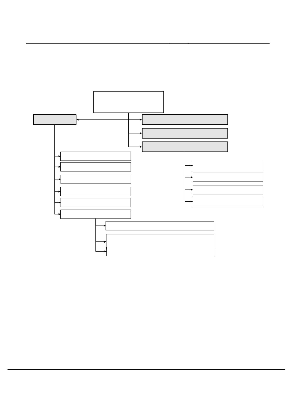
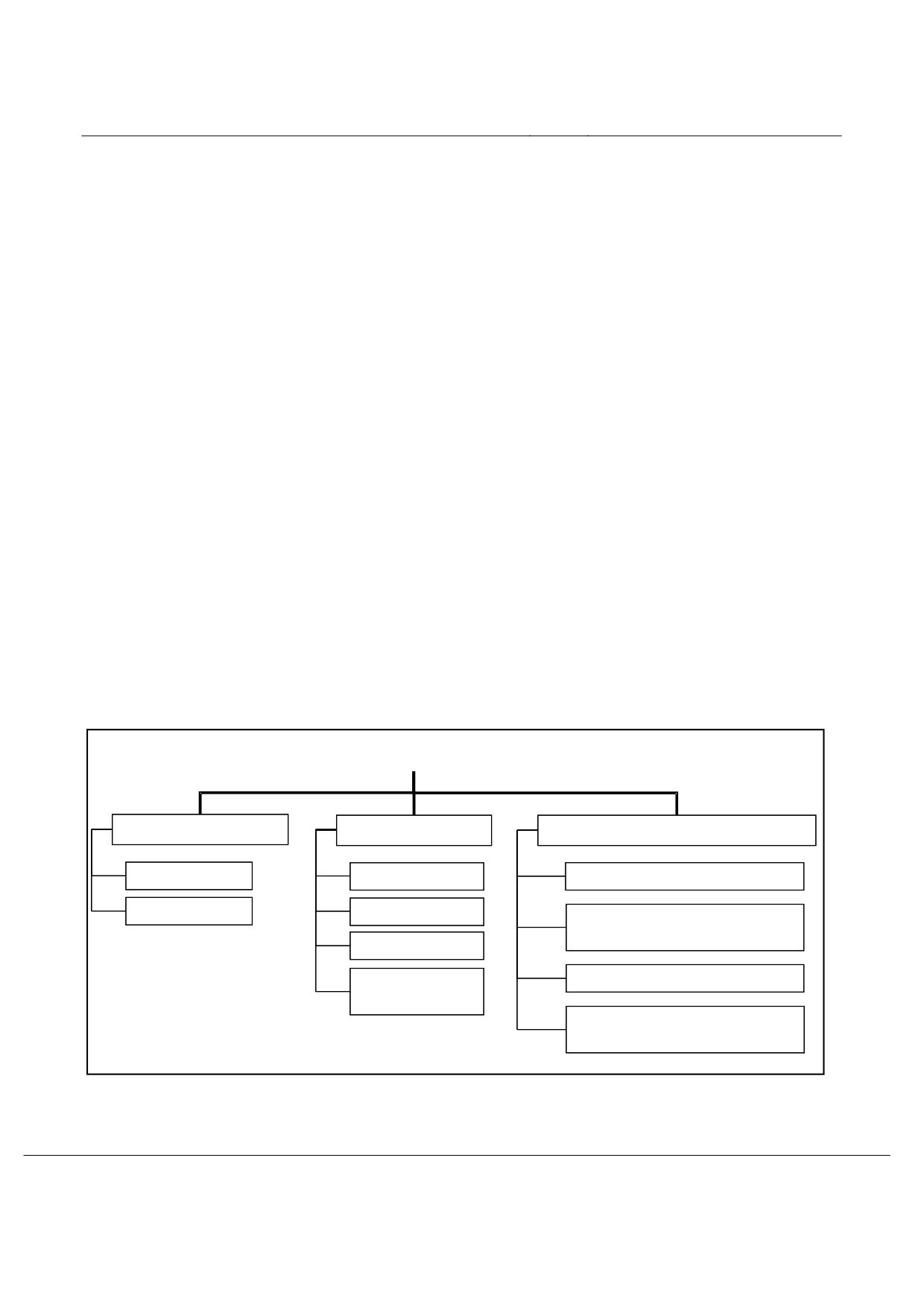
documents. The document tree is shown on figure 1 /MSB AG-GESAMTSYS/.
The overriding design principles, complete system and its annexes apply to the entire documentation:
• High-speed Maglev system design principles, doc. no.: 50630,
/MSB AG-GESAMTSYS/, with its annexes:
• Annex 1: Abbreviations and definitions, doc. no.: 67536,
/MSB AG-ABK&DEF/
• Annex 2: Laws, regulations, standards, and guidelines doc. no.: 67539, /MSB AG-NORM&RILI/
Title
High-speed Maglev system design principles
Guideway Part I - Overriding requirements
Doc.no.:
57284
Version
White paper
Issue date
15.02.2007
Page 8
High-speed Maglev system
Maglev Technical Committee
Design principles
Guideway
• Annex 3: Environmental factors, doc. no: 67285, /MSB AG-UMWELT/
• Annex 4: Rules of operation (vehicle operation and maintenance) doc. no.: 69061,
/MSB AG-BTR&IH/
• Annex 5: Noise, doc.no.: 72963, /MSB AG-SCHALL/
As well as the subordinate, applicable documents:
• High-speed Maglev system design principles, part I: General requirements, doc. no: 67698, /MSB AG-FZ
GEN/
• High-speed Maglev system design principles, part II: Design, doc. no: 67694, /MSB AG-FZ BEM/
• High-speed Maglev system design principles, part III: Kinematic gauge, doc. no.: 67650, /MSB AG-FZ KIN/
• High-speed Maglev system design principles, part IV: Support/guidance technology, doc. no: 73388, /MSB
AG-FZ TRAFÜ/
• High-speed Maglev system, design principles, part V: Braking technology, doc. no.: 73389, /MSB AG-FZ
BREMS/
• High-speed Maglev system design principles, propulsion and energy supply doc. no.: 50998, /MSB AG-ANT/
• High-speed Maglev system design principles, operational control systems, doc. no.: 53328, /MSB AG-BLT/
• High-speed Maglev system design principles, guideway part I: Overriding requirements, doc. no: 57284, /MSB
AG-FW ÜBG/
• High-speed Maglev system design principles, guideway part II: Design, doc. no: 57288, /MSB AG-FW BEM/
• High-speed Maglev system design principles, guideway part III: Geometry, doc. no.: 41727, /MSB AG-FW
GEO/
• High-speed Maglev system design principles, guideway part IV: Trassierung, Dok.-Nr.: 60640, /MSB AG-FW
TRAS/
• High-speed Maglev system design principles, part V: Surveying, doc. no: 60641, /MSB AG-FW VERM/
• High-speed Maglev system design principles, guideway part VI: Maintenance, doc. no: 63842, /MSB AG-FW
IH/
The following is a bullet point summary of parts I to VI of the high-speed Maglev system design principles,
guideway:
Part I Overriding requirements
(1)
Description of the structure of the guideway subsystem and its components;
(2)
Definition of functional and design requirements of the individual components/modules;
(3)
Definition of the verification procedure requirements;
(4)
Definition of the required QA measures;
(5)
Examples of tested system-related design and construction variations;
Part II Design
Title
High-speed Maglev system design principles
Guideway Part I - Overriding requirements
Doc.no.:
57284
Version
White paper
Issue date
15.02.2007
Page 9
High-speed Maglev system
Maglev Technical Committee
Design principles
Guideway
(1)
Definition of actions on the guideway (incl. vehicle/guideway interaction);
(2)
Definition of limit values for the guideway verification procedure (structural safety, material
fatigue and serviceability);
(3)
Definition of permissible deformations;
(4)
Verification procedure guidelines;
Part III
Geometry
(1)
Definition of the target geometry of the guideway and permissible deviations (tolerances in
the form of displacement, slope differences and gaps in functional levels);
(2)
Benchmark definition for surveying the functional levels;
Part IV
Line routeing
(1)
Guideway line routeing guidelines;
(2)
Definition of the permissible line routeing elements and routeing parameters;
Part V Surveying
(1)
Description of the application of available coordinate systems;
(2)
Requirements of the high-speed Maglev system coordinate system;
(3)
Surveying method requirements;
Part VI
Maintenance
(1)
General; requirements for guideway maintenance;
(2)
Fundamental requirements regarding the order of maintenance procedures;
(3)
Fundamental requirements for the creation and content of maintenance programmes for
guideway modules (incl. maintenance personnel requirements);
(4)
Definition of the requirements for special vehicles on the guideway;
Abbreviations and definitions
The abbreviations and definitions provided in /MSB AG-ABK&DEF/ apply.
Laws, regulations, standards, and guidelines
The normative documents listed in /MSB AG-NORM&RILI/ contain stipulations that are referred to in the
high-speed Maglev system design principles and thus form part of that document.
In the case of dated normative documents in /MSB AG-NORM&RILI/ later modifications or revisions of those
publications do not apply. In the case of undated references, the last edition of the normative document in
question applies.
Title
High-speed Maglev system design principles
Guideway Part I - Overriding requirements
Doc.no.:
57284
Version
White paper
Issue date
15.02.2007
Page 10

High-speed Maglev system
Maglev Technical Committee
Design principles
Guideway
The edition of the standards and guidelines
to be observed in a high-speed Maglev sys-
tem project must be bindingly agreed upon
for each specific project. Description and
obligation of requirements
Guidelines according to /DIN 820/ were generally used in the creation of this document.
In the following chapters and annexes of this document
- Requirements are shown in standard font
- Explanations, values and examples are shown in italics
Following the example of /DIN 820/, part 2, Annex G, the degree of obligation of the requirements has been determined
and reflected in the phrasing of the requirements.
Table 90 shows the verb forms that have been used from /DIN 820/, tables G1 to G4. The additional verb form "shall" /
"shall not" has also been added.
Meaning
Verb form
Paraphrase (only used in special cir-
Use
cumstances)
Requirement:
must
is to…
…
Order
is required
For binding requirements,
The requirement is that …
i.e. those that must be ob-
has to
served without alteration.
only … permissible
It is necessary
Requirement:
must not
is not permissible, [permitted], [authorized]
Prohibition
it is forbidden
is not to…
is not to
Requirement:
shall
The requirement is initially
Limited order
binding. However, in valid
special cases exceptions
may be allowed.
Individual necessary excep-
tions must be justified in
writing by the user and
Title
High-speed Maglev system design principles
Guideway Part I - Overriding requirements
Doc.no.:
57284
Version
White paper
Issue date
15.02.2007
Page 11

High-speed Maglev system
Maglev Technical Committee
Design principles
Guideway
Requirement:
shall not
verification of an equal
Limited prohibi-
level of safety and system
tion
compatibility must be pro-
vided.
Recommendation
should
It is recommended that …
Is generally …
When one of several options
is particularly recom-
mended, without referring
to or excluding other op-
tions, or when (negative
form) advising against a
should not
is not recommended
particular option, but not
should be avoided
forbidding it.
Permissibility
may
is permitted
…
is permissible
To convey that something is
… also …
allowed.
need not…
is not required
… is not necessary
Possibility
can
might
…
It is possible that …
To convey a possibility.
allows…
is able to …
can not
might not
It is not possible that …
does not allow…
Table 90:
Verb forms used
Title
High-speed Maglev system design principles
Guideway Part I - Overriding requirements
Doc.no.:
57284
Version
White paper
Issue date
15.02.2007
Page 12
High-speed Maglev system
Maglev Technical Committee
Design principles
Guideway
Operational systems
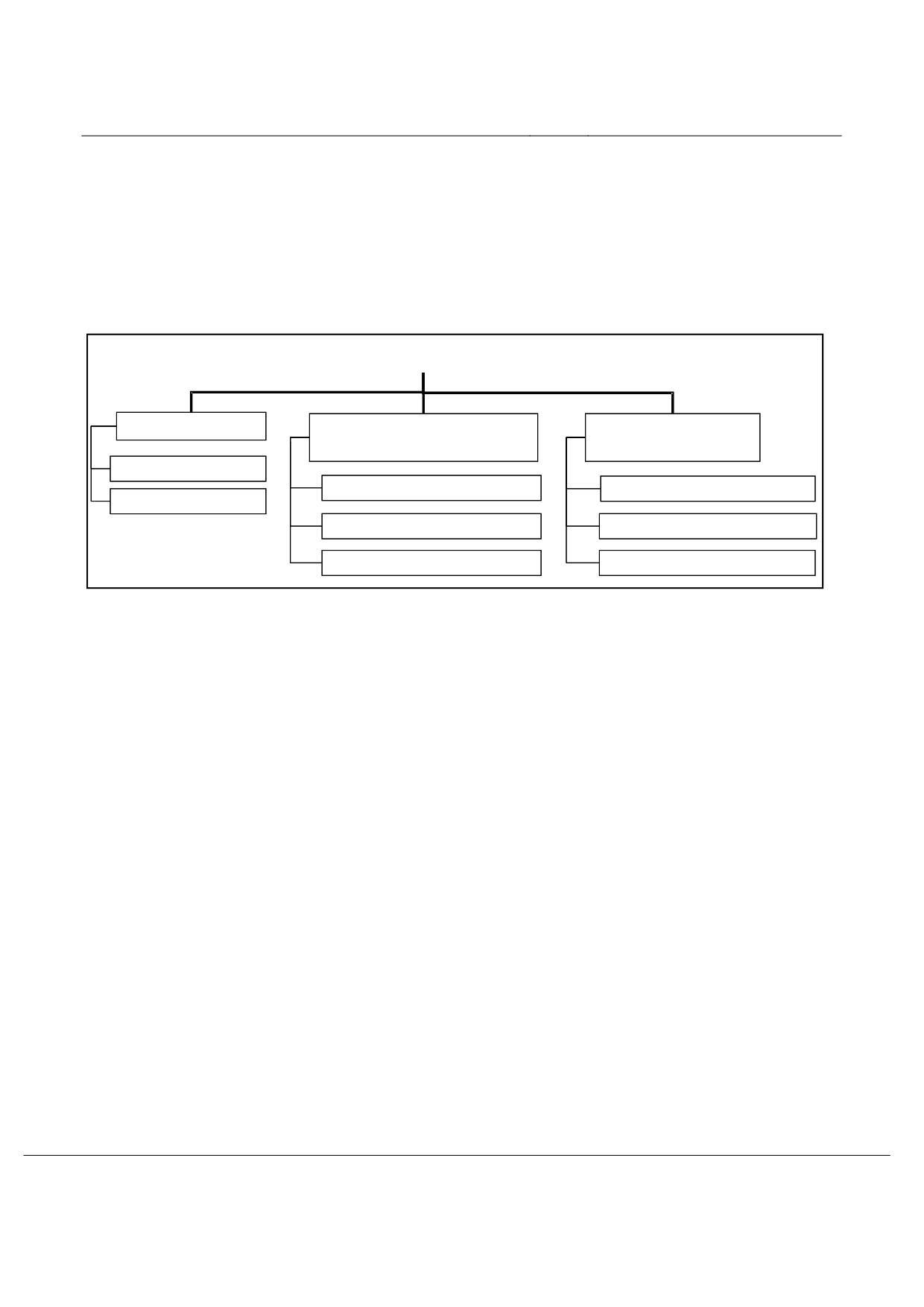
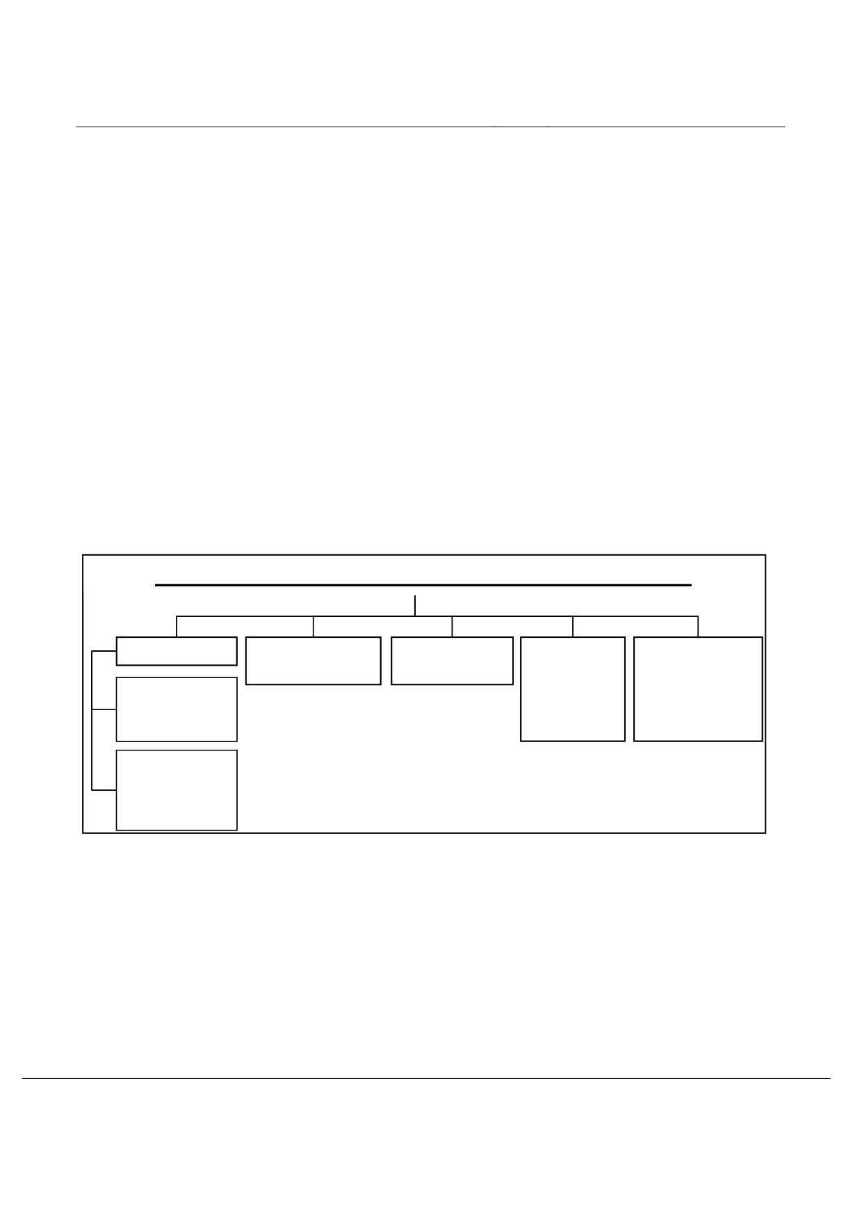
The static systems for the high-speed Maglev system are referred to as operational systems. They includes
the guideway, other structures and static facilities such as substations und stations.
Operational
systems
Guideway
Propulsion/energy supply
Operational control system
Other operational systems
Guideway superstructures
Operations centre
Guideway substructures
Stations
Track switching equipment
Substations
Special contructions
Maintenance systems
Route periphery
Guideway equipment
Maglev-specific guideway equipment
Construction style-specific guideway
equipment
Other constructions
Figure 104: Overview of operational systems
Title
High-speed Maglev system design principles
Guideway Part I - Overriding requirements
Doc.no.:
57284
Version
White paper
Issue date
15.02.2007
Page 13
High-speed Maglev system
Maglev Technical Committee
Design principles
Guideway
Overriding requirements
General
The overriding requirements for all guideway modules and components of the Maglev system are defined
below. The overriding guideway elements which form part of the operational systems can be seen on Figure
104.
Functional requirements
The overriding functional requirements relating to guideway modules/components are:
(1)
The guideway must safely resist all actions resulting from operation and from the environ-
ment and transfer them to the foundations.
(2)
Only tested components/modules should be used for Maglev operation. Otherwise it must be
verified that they are compatible with the complete system.
(3)
Throughout its required service life, the guideway must comply with the serviceability re-
quirements without fail, under the specific boundary conditions. The service life must be de-
termined for each individual project. 80 years can be used as a guide value.
(4)
Risk of spontaneous failure of the guideway and/or its elements must be eliminated.
(5)
The designs should be fault-tolerant and fault-revealing or redundant and fault-revealing.
(6)
Risk of clearance violations through breakdown/failure of a component or a module (break,
unacceptable deformation) and loss of function must be eliminated.
(7)
Deformation changes or changes in gradient and/or displacement in the function levels as a
result of failure (e.g. of fastening elements) must be recognisable during non-interruptive
checks, before permissible deformation, gradient or displacements are exceeded.
Design requirements
The following overriding design requirements must be observed when designing and constructing all compo-
nents/modules:
(1)
All components/modules must be constructed so that they are able to safely withstand the
specific action effects resulting from project-specific environmental conditions throughout
their entire service life.
(2)
The guideway must be designed so that the functional levels do not deviate in a non-
permissible way from the three-dimensional curve path under the simultaneous influence of
the actions from the vehicle and environment.
(3)
The vehicle operation must not be adversely affected by potential vibration of the guideway
as determined by the dynamic characteristics (stiffness, weight application, damping).
(4)
Environmental requirements must be taken into consideration for each specific project in
agreement with the responsible inspectorate. This includes, among others, wind, thermal,
precipitation, ice and seismic actions.
Title
High-speed Maglev system design principles
Guideway Part I - Overriding requirements
Doc.no.:
57284
Version
White paper
Issue date
15.02.2007
Page 14
High-speed Maglev system
Maglev Technical Committee
Design principles
Guideway
(5)
All guideway components/modules must be designed so that environmental emissions do not
exceed the permissible values (see relevant regulations and legislation incl. MbB0). If per-
missible emission limit values cannot be adhered to along the line, additional measures must
be implemented.
(6)
The suitability of the selected materials and manufacturing processes must be verified by
appropriate tests and/or certificates/documents/approval notifications.
(7)
Where guideways are installed in tunnels and enclosed spaces, the current requirements for
fire and catastrophe protection for guideways in tunnels or enclosed spaces must be ob-
served when selecting materials. Individual requirements must be determined for each pro-
ject.
(8)
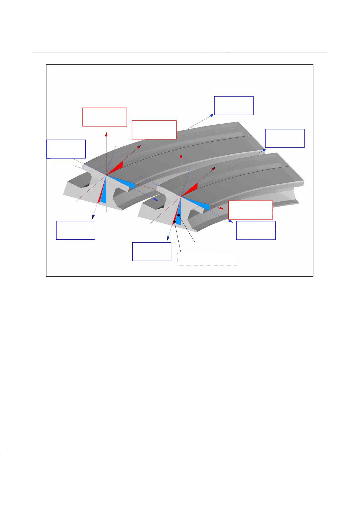
The position of the guideway is defined by the three-dimensional curves of the individual
tracks determined within the framework of the project-specific line routeing and the accom-
panying guideway transverse gradient information α. The defined guideway coordinate sys-
tems (local and global) for the positions of these three-dimensional curves and construction
(productions and assembly) of the guideway can be seen on Figure 105. The local coordi-
nate system (beam production coordinate system) is explained in design principles, guide-
way, part III "Geometry" /MSB AG-FW GEO/. The global coordinate system (high-speed
Maglev system coordinate system) is explained in design principles, guideway, part V "Sur-
veying" /MSB AG-FW VERM/.
(9)
The numbering of the guideway components/modules and other relevant details (bearing
arrangement, type, etc.) are to be included in the maintenance documentation and the build-
ing directory.
(10) It must be possible to carry out maintenance of the guideway; especially the guideway su-
perstructure and guideway equipment from the guideway surface (e.g. using special vehi-
cles). The guideway design should be maintenance-free, require little service and allow
automated inspection to be carried out.
Title
High-speed Maglev system design principles
Guideway Part I - Overriding requirements
Doc.no.:
57284
Version
White paper
Issue date
15.02.2007
Page 15
High-speed Maglev system
Maglev Technical Committee
Design principles
Guideway
x-direction
local li
direction
height (MKS)
direction
vertical (MKS)
x-direction
local re
y-direction
local li
direction
right (MKS)
z-direction
y-direction
local li
local re
z-direction
„α“ transverse gradient
local re
β“longitudinal
gradient
Figure 105: Local and global coordinate system
(11) Overriding values for clearance (loading gauge, kinematic envelope, boundary for fixed in-
stallations and the track centre distance) are defined in /MSB AG-GESAMTSYS/ If neces-
sary, deviations from these values must be approved by the responsible inspectorate. Space
requirements for guideway equipment are defined in /MSB AG-GESAMTSYS/.
(12) Space requirements for high-speed Maglev system-specific guideway equipment are shown
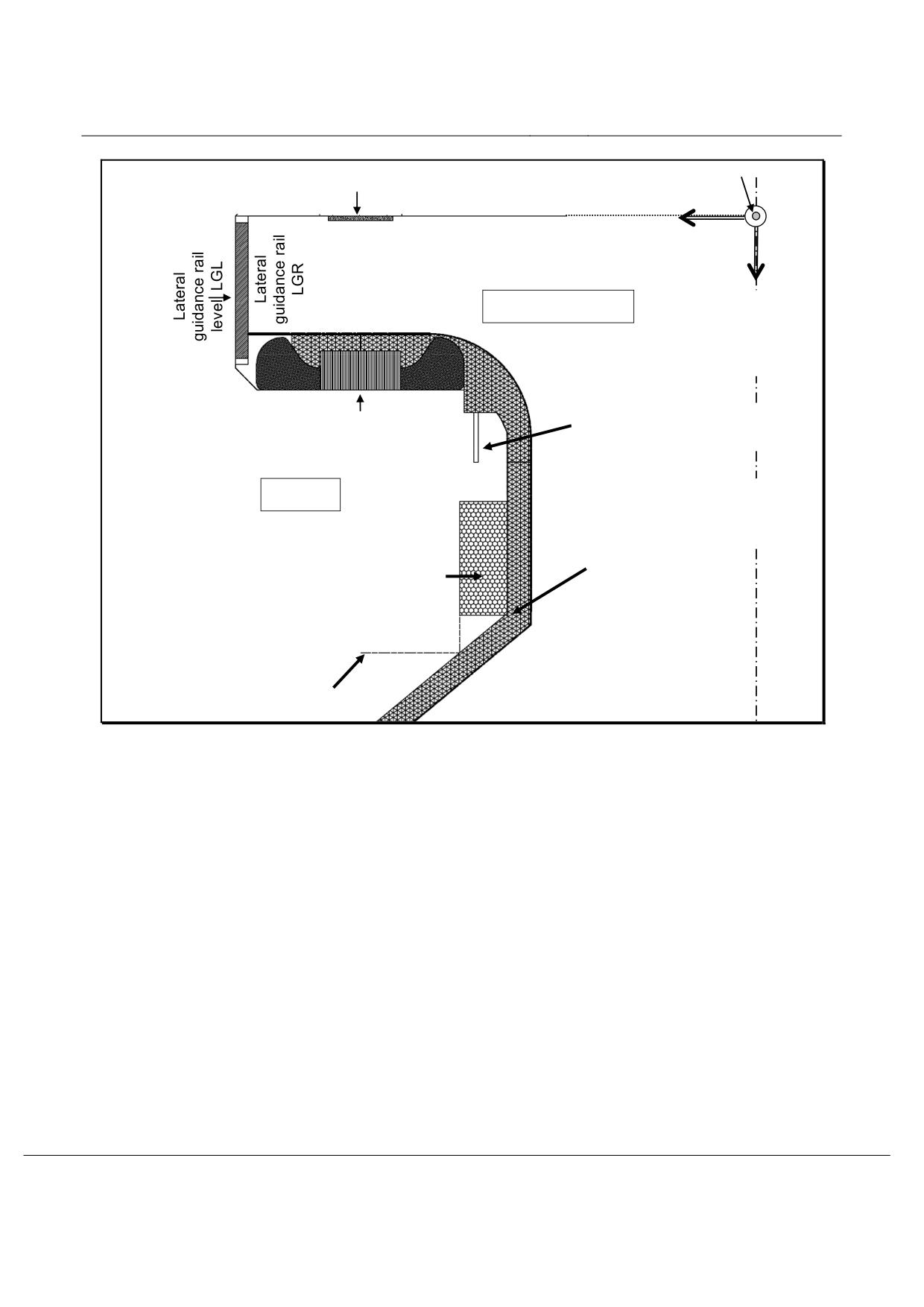
on the following Figure 106. Measurements for the space requirements are defined in /MSB
AG-FW GEO/ on the basis of /MSB AG-GESAMTSYS/.
(13) The maximum measurements for guideway superstructures provided as standard gauge in
the annex for standard guideway types should be adhered to.
Title
High-speed Maglev system design principles
Guideway Part I - Overriding requirements
Doc.no.:
57284
Version
White paper
Issue date
15.02.2007
Page 16
High-speed Maglev system
Maglev Technical Committee
Design principles
Guideway
Sliding surface GE
Three-dimensional curve
y
x
Sliding strip GL
z
Long stator
(stator pack with
Guideway beam
Guideway
motor winding)
beam middle
axis /
symmetry axis
Guideway-side positioning
Stator level SL
modules (e.g. PRS)
Vehicle
Space for attachment elements for
motor winding supply and other
project-specific guideway equipment
Guideway-side modules for the
external on-board energy supply
Vehicle boundary
Figure 106: Overview of the space requirements of the high-speed Maglev system-specific guideway equipment
(14) The system lengths of guideway superstructures must be derived from the interval of the
individual phases of the motor winding of 86 mm, which results from the pole pitch of the long
stator motor of 258 mm (3 · 86 mm), and the resulting model system lengths of a standard
stator pack of 1032 mm from 12 · 86 mm (n · 86 mm).
This results in the following potential control system span lengths (cf. Figure 111, 112, 113)
of the guideway superstructures:
- Guideway type I:
n · 24.768 m or n · 30.960 m (24 or 30 · 1.032 m);
− Guideway type II:
n · 12.384 m (12 · 1.032 m);
− Guideway type III:
6.192 m (6 · 1.032 m);
(with n = 1 for single-span beam and n ≥ 2 for two and multiple-span beams)
(15) The system lengths must relate to the three-dimensional curve. In the case of curved guide-
ways or guideways in dips or on hills, deviating lengths, which result on the functional levels
/MSB AG-FW GEO/ and /MSB AG-FW TRA/, must be taken into account.
(16) A guideway, whose gradient lies at least 3.5 m above the ground, must be designated as an
"elevated guideway”.
Guideway type I is normally used for this type of guideway.
Title
High-speed Maglev system design principles
Guideway Part I - Overriding requirements
Doc.no.:
57284
Version
White paper
Issue date
15.02.2007
Page 17
High-speed Maglev system
Maglev Technical Committee
Design principles
Guideway
(17) A guideway, whose gradient lies between 1.25 m and 3.50 m above the ground, must be
designated as an "at grade guideway”.
Guideway type II or III is normally used for this type of guideway. The minimum gradient height of an
at grade guideway depends on the existing transverse gradient of the installation area and project-
specific boundary conditions (e.g. potential snow accumulation).
Title
High-speed Maglev system design principles
Guideway Part I - Overriding requirements
Doc.no.:
57284
Version
White paper
Issue date
15.02.2007
Page 18
High-speed Maglev system
Maglev Technical Committee
Design principles
Guideway
Verification procedure
The following verification procedure requirements are overriding for all guideway components/modules:
(1)
The "Fundamentals of structural design" in Eurocode EN 1990 and DIN 1055-100 was used
as the basis for the structure verification procedure.
(2)
DIN VDE 0100 and DIN VDE 0101 were used as the basis of the verification procedure for
electrical components and modules.
(3)
The notes contained in the "Eisenbahnspezifischen Liste Technischer Baubestimmungen"
(ELTB) (List of railway technical construction regulations) drawn up by the EBA (Federal
Railway Authority) must be observed.
(4)
The verification procedure for all guideway components and modules must be carried out
using the following methodology, taking into account the actions resulting from the environ-
ment and operation detailed in /MSB AG-FW BEM/, the additional project-specific boundary
conditions (service life, operating parameters etc.) as well as complying with the generally
accepted technical rules and standards:
- Theoretical verification procedure
(calculations);
- Empirical verification procedure
(action effect measurements/test bench trials).
(5)
If the verification procedure and its parameters are not defined in existing regulations (e.g.
design principles, guideway, standards, guidelines, etc.) then they must be determined and
agreed upon with the responsible inspectorate.
(6)
The requirements of the high-speed Maglev system design principles must be adhered to
during the verification process of project independent standardised components/modules. If,
in exceptional cases, there are reasons why these requirements cannot be adhered to, it
must be verified that it is equally as safe and a serviceability verification must be carried out.
(7)
During the verification process, special attention must be paid to the dynamic excitation of
the guideway resulting from the vehicle (see /MSB AG-FW BEM/).
(8)
Environmental resistance and other characteristics such as effects on aerodynamics, noise,
etc. must be verified.
(9)
Potential time-dependent influences (e.g. subsidence of anti-corrosion coatings around
prestressed screw connections, creep of prestressed elements) must be taken into consid-
eration, and include a safety margin, in the verification procedure.
(10)
If there are no permissible limit values available for certain components/modules, then these
must be determined by test bench trials (e.g. component test, material test).
(11)
Untested construction methods, components and modules may only be used commercially
after they have undergone inspection and suitability tests in a test carried out under applica-
tion-specific boundary conditions.
(12)
In the case of untested materials, construction methods, components and modules, or un-
tested combinations, it must be demonstrated that they are compatible with the complete
system.
Title
High-speed Maglev system design principles
Guideway Part I - Overriding requirements
Doc.no.:
57284
Version
White paper
Issue date
15.02.2007
Page 19
High-speed Maglev system
Maglev Technical Committee
Design principles
Guideway
(13)
The influential action effects and combined action effects determined by the theoretical tests
should be reproducibly verified by measurements.
(14)
The theoretical hypotheses used in the verification process, in particular actions not yet
proven in a test run, must be verified by measurements during commissioning.
(15)
The guideway safety level should at the very least correspond to the safety level of similar
railway public transport.
(16)
The project-specific risk analysis created on the basis of DIN EN 50126 can result in exten-
sive safety-related requirements for the guideway and its components/modules.
(17)
During the verification process, all guideway components/modules must be assessed (e.g.
by FMEA) with regard to behaviour as the result of failure.
(18)
Failure of components/modules must be excluded with sufficient reliability, taking into ac-
count the consequences of failure and economic viability.
For fail-safe designs additional verification process requirements must generally be taken
into consideration:
- The influential action effects determined by the theoretical tests and the combined action
effects applied in the verification process must be empirically verified before commercial
use.
- Characteristics that are crucial for the correct functioning of the components/modules
(e.g. material, absence of cracks, strength, compliance with specified measurements,
pretensioning of screws) must be recognised as critical characteristics. For these charac-
teristics a complete test appropriate to the significance of the component must be carried
out.
(19)
Fault-tolerant designs can be achieved with robust construction, for example:
- Components/modules do not break down suddenly and/or loss of sufficient bearing ca-
pacity is signalled by "large"/timely visible deformations or formation of cracks.
(20)
Fault-tolerant designs can be verified by failure effect analysis (failure behaviour in the case
of component failure), for example:
- In the case of theoretical (sudden) failure of a component, it must be proven that through
load deflection, the bearing strength and the serviceability of all components and modules
lying in the force path can be relied upon during their remaining service life or until repair.
- Load deflection can be carried out with diverse or homogeneous redundant load paths. In
the event of component failure, it is permissible for the forces to be transferred along a
load path that is also in operation when the system is functional ("hot" redundancy).
- In the case of redundant load paths that are not directly used when the system is func-
tioning ("cold" redundancy), only the environmental actions and indirect actions from op-
eration (e.g. beam vibrations) need be considered.
- The failure situations to be detected must be determined in agreement with the responsi-
ble inspectorate for all affected components/modules taking maintenance into considera-
tion (failure detection, inspection intervals, etc.).
- In the event of a permissible fault reporting an operationally stable layout of the compo-
nents/modules lying in the force path, which are to be considered in the failure situation,
Title
High-speed Maglev system design principles
Guideway Part I - Overriding requirements
Doc.no.:
57284
Version
White paper
Issue date
15.02.2007
Page 20
High-speed Maglev system
Maglev Technical Committee
Design principles
Guideway
specifying the permissible load cycle (vehicle passing) is sufficient for a project-specific
utilisation profile. The permissible fault reporting/detection as part of guideway mainte-
nance must be verified.
(21)
The requirements to be fulfilled with regard to the necessary quality of the compo-
nents/modules must be clearly and fully defined.
(22)
If the evaluation methods for inspecting the required quality of the components/modules are
not laid down in the present standards, etc., then they must be determined in agreement with
the responsible inspectorate. Evidence that the evaluation methods were used in the evalua-
tion must be provided.
(23)
The production/assembly must be carried out in such a way that the boundary conditions
used as a basis for the verification process are adhered to, with proof. Production/assembly
instructions, which determine the processes and tools, all parameter values that must be ad-
hered to and the permitted tolerances of the parameters, must be drawn up.
(24)
The correct position of the high-speed Maglev system-specific guideway equipment must be
verified before the guideway is commissioned by a clearance test and an inspection of the
long and short wave deviations and the displacements.
(25)
Adherence to the following general requirements is a prerequisite for achieving the required
reliability und serviceability of the guideway:
- Qualified persons are appointed for the development, design and the verification process.
- It is constructed by carefully trained and qualified personnel.
- Appropriate supervision is ensured at the manufacturing plants, the production plants
and at the construction site.
- The guideway is used in accordance with the planning assumptions.
- The guideway elements are correctly maintained. Prerequisite for this is a maintenance
programme drawn up by the manufacturer.
Handling, transport and assembly
The manufacturer should draw up detailed instructions on handling, transport, assembly and disassembly for
all guideways. These must take specific boundary conditions into account (layout, actions as a result of
transport, etc.).
There is no need to create detailed instructions for handling, transport, assembly and disassembly for tried
and tested subordinate components/modules.
All manufacturing/assembly procedures must be documented as part of the verification procedure.
General requirements for maintainability
The following basic requirements for the maintainability of guideway components and modules must be ad-
hered to:
Title
High-speed Maglev system design principles
Guideway Part I - Overriding requirements
Doc.no.:
57284
Version
White paper
Issue date
15.02.2007
Page 21
High-speed Maglev system
Maglev Technical Committee
Design principles
Guideway
All guideway components and modules must be designed in a way that keeps maintenance expenditure to a
minimum. Fault-tolerant, robust and if possible redundant designs are preferred.
(1)
Guideway components and modules should be maintenance-free and require minimal ser-
vice.
(2)
Maintenance should only be planned when it is unavoidable (e.g. for moveable parts of the
track switching equipment) or if maintenance is more favourable economically or in terms of
operation in comparison to inspection/repair.
(3)
The requirements from chapter 5.3.3 in /MSB AG-GESAMTSYS/ and /MSB AG-BTR&IH/
with regard to maintenance must be taken into account in the design of the guideway com-
ponents and modules.
(4)
Damage must reveal itself so that it can be reliably detected during the appropriate inspec-
tion process.
(5)
Multiple failure of components/modules must be detectable by monitoring measures taking
the individual designs into account in accordance with /MSB AG-BTR&IH/ and must be able
to be restored to their normal state.
(6)
The failure of a single component or a single module should not cause problems or interrupt
vehicle operation.
Note: In the not entirely excluded event of entire guideway beams requiring replacement, vehicle op-
eration can be restricted.
(7)
During development and manufacture of the guideway, it is important to reduce the probabil-
ity of (or ideally prevent) repair measures being required.
(8)
Careful, error-free and proper manufacturing (assisted by a quality assurance system) will
result in a high-quality guideway.
(9)
All components and modules must be operationally stable, taking into consideration actions
resulting from the environment and operation, throughout their designed service life.
(10)
Designs that allow non-interruptive, predominantly automated inspection, are preferred.
(11)
If direct detection of failure is not possible, then it must be verified that a potential fault can
be detected indirectly (e.g. as a result of displacement changes on the functional level) be-
fore the fault becomes unacceptable.
(12)
All guideway components and modules must be constructed in a way that keeps inspection
to a minimum.
(13)
Modules and components must be marked in order to enable clear classification as part of
the automatic inspection process so that clear work orders can be issued.
(14)
The maintenance period must be defined according to the specific project.
Title
High-speed Maglev system design principles
Guideway Part I - Overriding requirements
Doc.no.:
57284
Version
White paper
Issue date
15.02.2007
Page 22
High-speed Maglev system
Maglev Technical Committee
Design principles
Guideway
Guideway superstructure
General
The guideway superstructures form the guideway tracks. See Figure 107 for the subdivision of guideway
superstructures.
Guideway superstructures
Guideway beam
Superstructure track
Other guideway
switching equipment
superstructures
Standard beam
Switches
Set-down/parkin
g guideway beams
Special beam
Traversers
Maintenance guideway beam
Swinging platforms
Calibration guideway beam
Figure 107: Types of guideway superstructure
(1)
When planning high-speed Maglev system routes, the following standard guideway beam
types (see. Figures 111, 112 and 113) should be used:
- Guideway beam type I: Single/multiple span beam with system lengths of
> ≈
16 m;
− Guideway beam type II: Single/multiple span beam with system lengths of
≤ ≈
16 m;
− Guideway beam type III: Multiple span plates with small system lengths of, for example,
≈
6 m;
(2)
The choice of standard guideway beam types and system lengths will depend on the project.
(3)
Guideway beam types I and II are generally discretely supported on columns with individual
foundations. The bearing pressure of guideway beam type III is generally transferred to the
foundations via strip footing.
(4)
For the guideway beams the following "construction methods" are currently being tested:
- Concrete construction (concrete beams/plates with integral (concrete) cantilever arms);
- Steel construction (steel beams/plates with integral (steel) cantilever arms);
- Hybrid construction (concrete beams/plates with attached steel modules as cantilever arms).
Other construction methods, such as composite constructions, are also possible.
(5)
Potential "designs" apply to the design of guideway superstructures (⇒ design-specific).
Title
High-speed Maglev system design principles
Guideway Part I - Overriding requirements
Doc.no.:
57284
Version
White paper
Issue date
15.02.2007
Page 23
High-speed Maglev system
Maglev Technical Committee
Design principles
Guideway
Functional requirements
The influential functional requirements for guideway superstructures are:
(1)
Reliable support of actions resulting from operation and the environment and transferral to
the guideway substructures;
(2)
Reliable support of the Maglev-specific guideway equipment;
(3)
Reliable support of other guideway equipment designs and methods;
(4)
Guarantee of required positional accuracy of the Maglev-specific guideway equipment (toler-
ances and deformations).
Design requirements
The design requirements for guideway superstructures are:
(1)
The cross section of the guideway superstructures should comply with the guidelines on Fig-
ures 106, 111, 112 and 113 as well as the defined installation space requirements for the
system guideway equipment in accordance with /MSB AG-FW GEO/, whereby all guideway
equipment connections should be accessible and serviceable in accordance with the design
layout.
(2)
The cross sections illustrated in Figures 106, 111, 112 and 113 may be exceeded if compati-
bility with the complete system is proven. The beam lengths provided are just examples (see
chapter (7) 0).
(3)
Materials (incl. corrosion protection) should be selected by taking into consideration the re-
quired service life according to state-of-the-art technology.
(4)
Maintenance expenditure and unfavourable acoustic effects (noise emissions) should be
kept to a minimum through an optimised cross section and surface design.
(5)
The general requirements on corrosion protection must be observed to ensure durability and
to minimise maintenance expenditure.
(6)
All load-bearing components should be easily accessible for maintenance purposes.
(7)
Box beams/cavities should be designed so there is no need to inspect the inside of them
(e.g. closed steel box beam).
(8)
The drainage for the guideway superstructures should be designed so that all rain water is
able to run off the guideway. Drainage via the lateral guidance rails is permitted. On straight
guideway areas, the guideway should be designed with a transverse gradient of 1.15° (cor-
responds to 2 %) for drainage.
(9)
Transverse gaps between successive guideway beams should be closed (e.g. by a beam
gap cover) if they can become larger than 20 mm (influencing variables: deformation of sub-
structures, variation in the length of the superstructure as a result of temperature and con-
crete creep and shrinkage) and lie in sections that have vehicle passing speeds in accor-
dance with the sectional actual travelling speed of > 150 km/h. The construction requirement
and areas affected are subject to project-specific definition.
Title
High-speed Maglev system design principles
Guideway Part I - Overriding requirements
Doc.no.:
57284
Version
White paper
Issue date
15.02.2007
Page 24
High-speed Maglev system
Maglev Technical Committee
Design principles
Guideway
(10) Longitudinal gaps and other openings on the guideway surface should be avoided.
(11) To enable components to be mounted on the guideway superstructures, suitable connection
points must be included in the design (e.g. spaces in reinforcing cage).
(12) If these connections affect the project independent structural verification of the guideway
superstructures (structural safety and fatigue strength) type approval, then these connections
must be taken into consideration when the verification process is created.The guideway su-
perstructures must be clearly numbered according to project-specific guidelines. Track num-
bering is carried out continuously. The numbers must be legible and permanently marked on
the upper surface of the guideway superstructures (if necessary above the relevant support
point). It is recommended that the numbers are also marked on the sides. The numbering of
the guideway superstructures and substructures must be coordinated.
(14) The design must ensure that the guideway superstructures can be inspected, as far as pos-
sible, with the aid of automated procedures (e.g. evaluation of video recordings).
(15) The design should ensure that repair measures that do not have to be planned well in ad-
vance (lead time < 3 months) can be carried out in the time available under all potential pro-
ject-specific environmental conditions.
Verification process
The overriding requirements for the guideway verification process specified in chapter 0 must be observed.
This applies to the following in particular:
(1)
In addition to the theoretical verification, guideway superstructures must be empirically clas-
sified with regard to the following characteristics:
- Verification of the dynamic behaviour and the dynamic action effects as the vehicle travels
over the guideway at a velocity between v = 0 km/h (with a levitating vehicle) and v = vmax;
- Verification of satisfactory bearing strength and service strength;
- Verification of serviceability
- Adherence to noise emission limit values according to /MSB AG-GESAMTSYS/;
- Verification of maintainability (ease of inspection, accessibility, etc.).
(2)
Research and findings from previous classifications (e.g. from a test run, from running appli-
cation projects) must be drawn upon during the verification process for new guideway super-
structures.
Handling, transport and assembly
(1)
Devices appropriate for the design must be used for the transport and assembly of guideway
superstructures to avoid mechanical damage and permanent deformation.
(2)
The assembly process and the fine positioning of the guideway superstructures must be op-
timised for precision, speed and be able to be carried out in all weathers. Assembly and posi-
tioning instructions must be drawn up with all required details.
Title
High-speed Maglev system design principles
Guideway Part I - Overriding requirements
Doc.no.:
57284
Version
White paper
Issue date
15.02.2007
Page 25
High-speed Maglev system
Maglev Technical Committee
Design principles
Guideway
Guideway substructures
General
The purpose of guideway substructures is to:
- bridge the height difference between the guideway substructures and the ground (guideway
supports);
- transfer forces from the guideway superstructures to the foundations taking system-related re-
quirements into account.
Concrete and steel designs are currently being tested for the columns. Other designs are also possible.
The guideway foundations are generally made of concrete.
The arrangement of the guideway substructures is primarily dependent on rigidity requirements, which are
determined by the permissible deformation and distortion according to /MSB AG-FW BEM/.
The aesthetic arrangement of the substructures depends on the following functional and design require-
ments.
See Figure 108 for the subdivision of guideway substructures.
Guideway substructures
Guideway foundation
Guideway support
s
Other guideway substructures
Standard foundation
Individual suppo
rts
Substructures in tunnels
Deep foundation
Frames
Substructures on
primary supproting structures
Support plates
Mass-spring system
Continuous
longitudinal beam
Substructures of
track switching equipment
Figure 108: Types of guideway substructures
Title
High-speed Maglev system design principles
Guideway Part I - Overriding requirements
Doc.no.:
57284
Version
White paper
Issue date
15.02.2007
Page 26
High-speed Maglev system
Maglev Technical Committee
Design principles
Guideway
Functional requirements
The influential functional requirements for guideway substructures are:
(1)
Guideway substructures must directly support the actions from the superstructures via the
guideway bearing and reliably transfer them to the foundations (reliable support from guide-
way superstructures).
(2)
Guideway equipment components and modules (e.g. motor winding power line and the ex-
ternal on-board energy supply) must be reliably incorporated.
(3)
Guideway substructures must permanently guarantee the required positional accuracy of the
superstructures.
Design requirements
The following design requirements must be considered when designing substructures:
(1)
Safety devices must normally be included according to the project-specific safety concept to
prevent impact of vehicles and devices on crossing and parallel routes.
(2)
Separate substructures for consecutive guideway superstructures should be avoided.
(3)
Dimensioned attachment points for connecting the guideway superstructure lightning protec-
tion system to the substructure reinforcement must be included in the design in accordance
with generally accepted technical rules and standards.
(4)
The design of the transitions between:
- Special structures and adjacent standard tracks,
- Discretely and continuously supported guideways and
- Guideways on mass-spring systems and adjacent guideways
must be verified as being compatible with the complete system.
(5)
To enable components to be fitted retrospectively on the guideway substructures, suitable
design measures must be included in the design (e.g. spaces in reinforcing cage). These
must be agreed upon for each specific project.
(6)
Attachment options for the long stator and external on-board energy supply cables must be
included on all columns in the design.
(7)
The guideway superstructures for the two tracks of the double track guideway should rest on
shared substructures that are arranged radial to the line routeing axis.
Deviations from this are permitted e.g. in the case of expansion of the track centre distance or use
of guideway beam type III. Sensitive areas of the guideway substructures (e.g. the area around the
guideway support) must be designed so that damage can be detected through automated guide-
way inspection procedures
Title
High-speed Maglev system design principles
Guideway Part I - Overriding requirements
Doc.no.:
57284
Version
White paper
Issue date
15.02.2007
Page 27
High-speed Maglev system
Maglev Technical Committee
Design principles
Guideway
Verification process
The overriding requirements for the guideway verification process specified in chapter 0 must be observed.
The following requirements should be highlighted:
(1)
When designing guideway substructures pay attention to the following project-specific points:
- Actions resulting from the superstructures, environment and operation;
- Permissible deformations;
- Static system for each guideway superstructure;
- Local foundation conditions;
- Local gradient heights of the tracks.
(2)
When designing the foundations the (high) loading velocity and the dynamic forces (fre-
quency, amplitudes) from the superstructures must also be observed.
(3)
If there is no research available for a substructure construction type, then extensive theoreti-
cal and/or empirical verification must be provided.
Handling, transport and assembly
Guideway substructures are generally created by cast in-situ concrete methods. If using prefabricated parts
(concrete prefabricated parts, stanchions, composite supports) then corresponding instructions for handling,
transport, assembly must be created.
Title
High-speed Maglev system design principles
Guideway Part I - Overriding requirements
Doc.no.:
57284
Version
White paper
Issue date
15.02.2007
Page 28
High-speed Maglev system
Maglev Technical Committee
Design principles
Guideway
High-speed Maglev system-specific guideway equipment
General
"High-speed Maglev system-specific guideway equipment" includes all components and modules that are
necessary for the operation of the train irrespective of the guideway construction (see Figure 109 and Figure
114).
The high-speed Maglev system-specific guideway equipment consists of:
- Long stator;
- Lateral guidance rails;
- Gliding strips;
- Guideway-side components for the external onboard energy supply;
- Guideway-side components for positioning;
- Lightning protection and earthing of guideway equipment..
The following describes the general requirements of high-speed Maglev system-specific guideway equip-
ment elements.
Maglev-specific guideway equipment
Long stator
Lateral guidance
Sliding strip
Guideway-side
Guideway-side
(inc. attachment)
(inc. attachment)
positioning
components for
component
the external on-
Stator pack
(inc. attach-
board energy
(inc. attachment
ment)
supply (inc. at-
tachment)
Motor winding
with earthing
(inc. attachment)
Figure 109: High-speed Maglev system-specific guideway equipment
Title
High-speed Maglev system design principles
Guideway Part I - Overriding requirements
Doc.no.:
57284
Version
White paper
Issue date
15.02.2007
Page 29
High-speed Maglev system
Maglev Technical Committee
Design principles
Guideway
Long stator
General
The long stator is part of the guideway and is used to propel Maglev vehicles.
It consists of the following elements:
(1)
Stator pack, made up of:
- An electric sheet steel pack with slots to receive the motor windings and to receive inte-
grated elements for attachment to guideway superstructures
(An example stator pack is shown in Figure 115 in the annex);
- Integrated elements for attachment to the stator pack on the guideway superstructure
(e.g. slot traverses);
- Protective coating (corrosion protection).
(2)
Elements for attaching the stator packs to guideway superstructures (i.e. screws);3-phase
motor winding (Figure 116 shows part of a long stator with a motor winding whose cables are
individually laid one after the other);
(4)
Motor winding earthing and additional fixture for the motor winding in the stator pack slots
(e.g. earthing sleeves and cable).
Figure 117 and Figure 118 in the annex show an example of a redundant stator pack attachments solution.
The long stator is directly protected from lightning strike due to its position under the guideway. However, to
avoid damage from indirect actions as a result of lightning strike, it must be guaranteed that lightning is con-
ducted through the attachment in the supporting structure’s earthing system.
Functional requirements
Stator packs
The interface between stator pack and motor winding must be designed so that the motor winding stays
safely in place under all considered actions in accordance with /MSB AG-FW BEM/.
The stator pack performs the following functions:
(1)
Controls the magnetic flux created by the vehicle support magnets, receives and conducts
the forces generated by the magnetic flux (bearing forces);Receives and transfers the accel-
eration and braking force;
(2)
Forms the reference surface (stator level) for measuring the air gap between stator pack and
support magnet;
(3)
Forms the reference surface for guideway monitoring (e.g. position monitoring using dis-
placement measurement);
(4)
Forms the tooth-slot effect for vehicle positioning;
(5)
Forms the tooth-slot geometry for flux modulation to induce an electrical voltage in the vehi-
cle’s linear generators (on-board energy supply).
Title
High-speed Maglev system design principles
Guideway Part I - Overriding requirements
Doc.no.:
57284
Version
White paper
Issue date
15.02.2007
Page 30
High-speed Maglev system
Maglev Technical Committee
Design principles
Guideway
Attachment of stator pack
The following requirements must be taken into consideration for attaching stator packs to the guideway su-
perstructures:
(1)
The stator pack attachment must reliably hold the stator pack in place through all actions
resulting from the environment and operation throughout the duration of the project-specific
service life, according to /MSB AG-FW BEM/ see /MSB AG-FW GEO/).
(2)
If the failure of one or more attachment elements cannot be excluded, limited safe vehicle
operation must be guaranteed for a time period to be defined on a project-specific basis.
(3)
Failure of attachment elements must be detectable by monitoring measures in accordance
with /MSB AG-BTR&IH/ and elements must be able to be restored to their normal state.
(4)
Violation of the permissible position deviations of the stator packs according to /MSB AG-FW
GEO/ must be prevented.
Motor winding
(1)
An electrical moving field is created via the motor winding, from which a thrust force for ac-
celeration and deceleration of the vehicle is created through interaction with the magnetic
field of the vehicle support magnet.
(2)
The thrust forces are transferred to the supporting structure via the stator packs and their
attachments.
Design requirements
Stator pack
(1)
The stator pack components (sheet pack, coating and the integrated attachment elements)
must be designed and assembled so that they meet the required service life taking into con-
sideration actions from the environment and operation in accordance with /MSB AG-
GESAMTSYS/.
(2)
It should be designed so as to minimise maintenance expenditure.
(3)
The quality of the electric sheet must meet the requirements of /MSB AG-GESAMTSYS/.
(4)
The stacking factor of the sheet pack must not be less than 0.97 according to EN 10106.
(5)
Normative dimensions of the sheet pack must be taken into consideration in accordance with
/MSB AG-GESAMTSYS/;
(6)
Stator pack length:
The system length of a stator pack is 1032 mm.
Due to the different lengths between the inside and outside of a curve, different physical sta-
tor pack lengths are required to create the guideway geometry.
The mechanical distance to the front surface of the stator packs should equal 0.5 mm to
2 mm in the support area. In areas with a small horizontal radius and in the case of track
switching equipment, a maximum range of 0 to 10 mm must be adopted.
Title
High-speed Maglev system design principles
Guideway Part I - Overriding requirements
Doc.no.:
57284
Version
White paper
Issue date
15.02.2007
Page 31
High-speed Maglev system
Maglev Technical Committee
Design principles
Guideway
The required lengths of the individual stator packs and their arrangement on the guideway
are project-specific and must be compatible with the vehicle levitation and guidance system.
(7)
The geometry of the mounted stator packs must (taking into consideration the project-
specific tolerances of the guideway attachment surface) meet the tolerance requirements of
the stator level as defined in /MSB AG-FW GEO/.
(8)
A consistent tooth-slot geometry must be adhered to with a grid of 86 mm.
(9)
The coating material (corrosion protection) should be selected by taking into consideration
the required service life and project-specific environmental factors. Suitable design and pro-
duction measures should ensure that the permissible coating thickness on the stator level is
not exceeded, thereby reducing the mechanical gap to an unacceptable level. The coating
must not affect the electrical and electromagnetic properties of the sheet pack. The corrosion
protection must completely cover the stator pack. It should also be permanently ductile and
resistant to abrasion.
(10) The maximum permissible thickness for the corrosion protection on the stator levels may not
exceed 1.8 mm (incl. all tolerances, tapers, etc.).
(11) The permissible stator pack installation space is shown on Figure 106 and in /MSB AG-FW
GEO/.
(12) The dimensions of the integrated attachment elements must be defined according to the type
of attachments, the static requirements and taking into consideration maintenance factors.
(13) The contact surfaces between the guideway cantilever arm and integrated elements for at-
taching the stator pack (e.g. slot traverse) must be designed so that the forces from the envi-
ronment and operation cannot lead to unacceptable displacement of the stator packs.
(14) For the transfer of forces from actions to be considered, the contact surfaces between the
stator pack attachment and the connecting surface on the supporting structure must satisfy
the friction parameter that is used as the basis for the dimensioning.
Attachment of stator packet
(1)
The attachment must be reasonably simple to detach without causing any damage to adja-
cent structures.
(2)
It must be determined, on a project-specific basis, whether the falling off of failed attachment
elements resulting in danger to third-parties must be prevented by implementing protection
measures on project-specific guideway sections (e.g. at intersections with other infrastruc-
ture).
(3)
Attachment elements, whose failure cannot be excluded, must be easy to replace (in be-
tween operating periods) in the event of their failure.
(4)
The construction-specific connection design (guideway cantilever arm and integrated ele-
ments for stator pack attachment) must be taken into consideration in the development and
dimensioning of attachment elements.
(5)
The space available for the stator pack attachment (see Figure 106 und /MSB AG-FW GEO/)
must be defined in agreement with the suppliers of the stator pack and the guideway beam.
It must be individually verified as compatible with the complete system.
Title
High-speed Maglev system design principles
Guideway Part I - Overriding requirements
Doc.no.:
57284
Version
White paper
Issue date
15.02.2007
Page 32
High-speed Maglev system
Maglev Technical Committee
Design principles
Guideway
(6)
Materials and manufacturing methods must be used that, in the event of a systematic failure,
will not lead to a failure of the attachment (e.g. hydrogen embrittlement). The costs associ-
ated with using such materials and methods must be kept within reasonable limits.
(7)
When selecting materials, the environmental influences (corrosion and ageing behaviour)
must be taken into account with regard to the required service life .
Motor winding
(1)
The motor winding must be designed so that the required service life is achieved, taking into
consideration the specified actions from the environment and operation.
(2)
Violation of the permissible clearance during the required service life must be excluded (tak-
ing specified actions from the environment and operation into consideration).
(3)
The mechanical and geometrical characteristics of the cable used for the motor winding must
be taken into consideration during the project-specific design of the attachment and assem-
bly (attachment in stator pack slots taking into account the motor winding earthing and the
tooth-slot geometry).
(4)
The permissible minimum bending radius of the motor winding cable and the permissible
installation space for the motor winding according to Figure 106, /MSB AG-FW GEO/ and
/MSB AG-GESAMTSYS/ must be adhered to.
(5)
The requirements for the electrical function of the motor winding are defined in /MSB AG-
GESAMTSYS/.
(6)
The requirements for the motor winding earthing result from the long stator protection and
can be found in Maglev design principles, propulsion and energy supply /MSB AG-ANT/.
(7)
The motor winding cable must be self-extinguishing to prevent fire.
(8)
Additional requirements for the motor winding material in tunnels and at stations (enclosed
spaces) can be defined on a project-specific basis (toxicity in the event of fire).
(9)
The earthing design and the connection points for the motor winding must be determined on
a project-specific basis, whereby the connection points for the motor winding earthing must
be integrated into the earthing/lightning protection system of the guideway.
(10)
On beam joints it must be ensured, through dimensionally stable arrangement of the motor
windings, that movement of the beams in the x-, y- and z directions, resulting from operation
and environment throughout the course of the required service life, does not lead to violation
of the permissible installation space and to loss of serviceability.
(11)
The determination of the local phase position of the motor winding must include verification
of compatibility with the complete system. (see /AG MSB-GESAMTSYS/ chapter 8.2 fig. 5)
(12)
An example of the 3-phase motor winding can be found in the annex (Figure 116).
(13)
The interface between stator pack and motor winding must be designed so that the motor
winding stays safely in place under all considered actions in accordance with /MSB AG-FW
BEM/.
Verification process
Title
High-speed Maglev system design principles
Guideway Part I - Overriding requirements
Doc.no.:
57284
Version
White paper
Issue date
15.02.2007
Page 33
High-speed Maglev system
Maglev Technical Committee
Design principles
Guideway
Stator packs
The following component/module-specific requirements for the stator pack must also be observed as well as
the overriding requirements for the guideway verification process specified in chapter 0.
(1)
The verification process must focus on the following:
- Verification of the fatigue resistance taking into account dynamic loads;
- Verification of the dimensional accuracy, quality and durability of the coating;
- Verification of the electrical and electromagnetic characteristics.
(2)
To ensure the quality of every individual stator pack a test instruction must be created that
contains all the acceptance criteria to be verified along with the permissible tolerances. The
acceptance tests must be recorded.
(3)
For traceability, all stator packs must be clearly, individually and permanently marked.
Attachment of stator pack
The following component/module-specific requirements for the stator pack attachment must also be ob-
served as well as the overriding requirements for the guideway verification process specified in chapter 0.
(1)
Verification must also be drawn up for failure situations, assuming that failure of attachment
elements is not excluded. The failure situations to be considered in connection with the de-
tection system must be determined after verification of compatibility and in agreement with
the responsible inspectorate.
(2)
It must be verified that for the failure situations all the components and modules in the force
path are designed for the entire project-specific service life.
(3)
In the event of a credible fault appearance, an operationally stable design of the compo-
nents/modules in the force path in the failure situation, specifying the permissible load cycle
(vehicle passing), is sufficient. Credible fault appearance/detection as part of guideway main-
tenance must be verified.
Motor winding
The following component/module-specific requirements for the motor winding must also be observed as well
as the overriding requirements for the guideway verification process specified in chapter 0.
(1)
Adherence to the specified thermal behaviour of the long stator must be verified metrologi-
cally during operation.
(2)
The theoretical load assumptions and serviceability must be verified by measurements both
during prototype development as well as during operation of the final system.
(3)
The current carrying capacity of the circuit, the shield and the electric strength of the wind-
ings must be verified.
(4)
The fatigue resistance of the winding attachment, including the dimensional stability of the
winding head, must be verified empirically.
(5)
The material and structural strength of the motor winding must be verified through the me-
chanical load on the beam joint.
Title
High-speed Maglev system design principles
Guideway Part I - Overriding requirements
Doc.no.:
57284
Version
White paper
Issue date
15.02.2007
Page 34
High-speed Maglev system
Maglev Technical Committee
Design principles
Guideway
(6)
Adherence to the lightning-impulse strength in accordance with /MSB AG-UMWELT/ as well
as project-specific instructions must be verified.
(7)
The permissible continuous current RMS value and current max. value must be empirically
verified, taking into consideration the project-specific cycle time parameter and running time.
(8)
It must be verified that the long stator protection is functioning correctly (earth-fault monitor-
ing).
Handling, transport and assembly
Stator packs
Instructions on handling (transport and storage)and assembly must be drawn up for the stator
pack. The following factors must be included:
(1)
Mechanical damage must be prevented by appropriate transport methods and packaging to
protect against impact.
(2)
The intermediate storage surfaces must be designed so that the stator packs and and/or
their transport packaging can be correctly set down and lifted again without causing any
damage.
(3)
The stator packs should be attached to the guideway superstructures by the manufacturer.
(4)
If stator packs are fitted retrospectively at the site, then additional construction documents
(assembly instructions and acceptance specifications) must be drawn up and verified as be-
ing compatible with the complete system and submitted to the responsible inspectorate for
inspection.
Attachment of stator pack
(1)
The assembly process and parameters must be specified in transport, storage and assembly
instructions.
(2)
The assembly parameters, such as starting torque/rotation angle, must be defined, moni-
tored and documented.
(3)
Connecting parts that have been used before (e.g. screws, washers, nuts) should not be
reused. In exceptional cases (e.g. use of inserts that are embedded in concrete with thread
(see Figure 117)) it must be checked whether the part is reusable before replacing the stator
pack or attachment element.
Motor winding
(1)
Detailed instructions for assembly, transport and intermediate storage must be drawn up in
the form of assembly instructions according to the specific project and design employed.
(2)
The free space within the gauge for the kinematic space requirement of the vehicle according
to /MSB AG-GESAMTSYS/ (or beyond, following project-dependent agreement) is available
for the manufacture and/or laying of windings from the guideway.
(3)
Assembly devices for the long stator motor winding must fulfil the special vehicle require-
ments.
Title
High-speed Maglev system design principles
Guideway Part I - Overriding requirements
Doc.no.:
57284
Version
White paper
Issue date
15.02.2007
Page 35
High-speed Maglev system
Maglev Technical Committee
Design principles
Guideway
Lateral guidance rails/lateral guidance levels
General
The lateral guidance rails, which are an element of the high-speed Maglev system-specific guideway equip-
ment, receive the mechanical and electromagnetic actions from the vehicle and special vehicles..
The fundamental arrangement of the lateral guidance rails on the cantilever arms of the guideway super-
structures can be found in Figure 106 and /MSB AG-FW GEO/.
Functional requirements
Lateral guidance rails
The lateral guidance rails perform the following functions:
(1)
Guide the magnetic flux from the guidance and braking magnet;
(2)
Enable the generation of electrical eddy currents by interacting with the braking magnets;
(3)
Receive the magnetic forces generated by the guidance and braking magnets and transfer
them to the cantilever arm structure;
(4)
Receive the forces initiated by special vehicles and transfer these to the cantilever arm struc-
ture;
(5)
Mechanical guidance in the event of failure of the magnetic guidance function of the guid-
ance magnets;
(6)
Mechanical guidance of the braking magnets on the lateral guidance rails, receive and trans-
fer the forces;
(7)
Forms the reference surface for measuring the air gap between guidance magnet and lateral
guidance rail;
(8)
Forms the reference surface for guideway monitoring (e.g. displacement or displacement
change detection);
(9)
Transferral of excess voltage resulting from lightning on the vehicle;
(10) Lightning protection function for the motor winding.
Attachment of lateral guidance rails
(1)
The attachment elements must reliably transfer the forces from the lateral guidance rails to
the cantilever arm of the guideway superstructures.
Design requirements
Lateral guidance rails
(1)
The lateral guidance rails should follow the course of the three-dimensional curve (transverse
gradient, dips/hills, curves).
Title
High-speed Maglev system design principles
Guideway Part I - Overriding requirements
Doc.no.:
57284
Version
White paper
Issue date
15.02.2007
Page 36
High-speed Maglev system
Maglev Technical Committee
Design principles
Guideway
(2)
Subject to the design used for the support, the lateral guidance rails may have a polygonal
arrangement if it can be verified that this is compatible with the complete system.
(3)
It must be guaranteed that inspection equipment will detect geometry changes and/or dis-
placement before the permissible limit values for these deformations is exceeded.
(4)
The range of possible materials for lateral guidance rails is defined in /MSB AG-
GESAMTSYS/.
(5)
Geometry:
- Thickness: tLGR ≥ 30 mm
− Height: HLGR≥ 300 mm
- Length: Depending on the system, beam-length lateral guidance rails are advantageous.
Shorter lengths can be used depending on the project.
(6)
It must be verified that lateral guidance rails with segment lengths shorter than approx 3.0 m
are compatible with the complete system. The edges of lateral guidance rails must be
rounded on the joints within a carrier field or a beam joint according to the instructions in
/MSB AG-FW GEO/.
(7)
The requirements for the levelness and positional accuracy of lateral guidance rails are listed
in /MSB AG-FW GEO/.
(8)
The lateral guidance rails must be given a coating that will barely be damaged by potential
mechanical loads and guarantee sufficient resistance to corrosive attack from the environ-
ment (see DIN EN ISO 12 944 Part 1 - 8 and TL 918300, page 87).
(9)
The suitability of the coating must be proven with regard to the vehicle side guidance gap
measurement (guidance gap sensors).
(10) The coefficients of friction must be adhered to in accordance with /MSB AG-FW BEM/.
(11) The lateral guidance rails must be connected to the guideway lightning protection system.
Attachment of lateral guidance rails
(1)
The attachment elements for the lateral guidance rails must be designed, according to the
selected design, so that they can safely and reliably withstand all actions to be considered
from the environment and operation throughout the required service life (see /MSB AG-
GESAMTSYS/).
(2)
The attachment of the lateral guidance rails must not affect the correct functioning of the
guidance sensors in an unacceptable manner. The guidance gap measurement areas are
shown in /MSB AG-FW GEO/. If attachment elements are absolutely necessary in these ar-
eas, then the suitability of the design must be verified with regard to the guidance gap meas-
urement.
(3)
The attachment must be optimised with regard to maintainability (ease of access for inspec-
tion and repair).
Verification procedure
Lateral guidance rails
The overriding requirements for the guideway verification process specified in chapter 0 must be observed.
Title
High-speed Maglev system design principles
Guideway Part I - Overriding requirements
Doc.no.:
57284
Version
White paper
Issue date
15.02.2007
Page 37
High-speed Maglev system
Maglev Technical Committee
Design principles
Guideway
Attachment of lateral guidance rails
The requirements according to chapter 0 (stator pack attachment) must be observed alongside the overrid-
ing requirements for the guideway verification process given in chapter 0.
Handling, transport and assembly
(1)
The lateral guidance rails and their attachment elements (specific to the design) must be
handled correctly.
(2)
The lateral guidance rails are normally attached to the guideway beams or guideway plates
by the manufacturer as integrated parts of the supporting structure of the guideway super-
structure or cantilever arm.
(3)
If lateral guidance rails are fitted retrospectively, then construction documents (assembly
instructions and acceptance specifications) must be drawn up and verified as being compati-
ble with the complete system and submitted to the responsible inspectorate for inspection.
Gliding strips/gliding surfaces
General
The gliding strips, which are an element of the high-speed Maglev system-specific guideway equipment, are
required during normal operation to deflect the mechanical forces from the stationary set-down vehicle via
the support skids and to receive the mechanical actions from special vehicles. In the event of a malfunction,
the force of the support skids from the moving vehicles are to be transferred to the guideway superstruc-
tures.
Functional requirements
The gliding strip performs the following functions:
(1)
The gliding strip and its attachment element must be made so that they can reliably with-
stand the specified mechanical and thermal loads along with project-specific environmental
conditions throughout the required service life in accordance with /MSB AG-GESAMTSYS/.
(2)
Forms a fault-tolerant gliding surface with surface conditions defined on a project-specific
basis for the mechanical support/gliding of the vehicle support skids;
(3)
Receives the forces in the x-, y- and z-directions resulting from the support skids incl. the
voltages resulting from temperature changes due to support skid friction as well as transfer-
ring these to the guideway superstructures;
(4)
Receives the forces in the x-, y- and z-directions resulting from special vehicles as well as
transferring these to the guideway superstructures;
Design requirements
Gliding strip/gliding surface
(1)
The gliding strip can be designed as follows:
Title
High-speed Maglev system design principles
Guideway Part I - Overriding requirements
Doc.no.:
57284
Version
White paper
Issue date
15.02.2007
Page 38
High-speed Maglev system
Maglev Technical Committee
Design principles
Guideway
- As an integral part of the beam or plate (e.g. part of the deck plate);
- Attached as a sealed, screwed or dowelled joint to the cantilever arm;
- Indirectly attached to the cantilever arm (e.g. as an integral part of a functional module).
The position of the gliding surface is shown on Figure 106 and in /MSB AG-FW GEO/.
(2)
The gliding surface must follow the course of the three-dimensional curve, taking the trans-
verse gradient into account.
(3)
Subject to the design, the gliding surface elements may have a polygonal arrangement if it
can be verified that this is compatible with the complete system.
(4)
Steel should be used for the gliding strips. If other materials are used, their suitability must be
verified.
(5)
Gliding surfaces must be given a coating that will barely be damaged by potential mechanical
loads and guarantee a high degree of resistance to corrosive attack from the environment -
including under conditions of mechanical stress (for metal gliding surfaces, see DIN EN ISO
12 944 Part 1 - 8 and TL 918300 page 87).
(6)
Geometry:
- Thickness: Depends on static requirements
- Width:
BSS ≥ 150 mm
- Length:
Depending on the system, beam-length gliding surface elements are advantageous.
Shorter lengths can be used depending on the project.
(7)
It must be proven by extensive verification that gliding surface elements with segment
lengths shorter than approx 3.0 m are compatible with the complete system.
(8)
The requirements for the levelness and positional accuracy of gliding surfaces are listed in
/MSB AG-FW GEO/.
(9)
It must be guaranteed that inspection equipment (according to /MSB AG-GESAMTSYS/) will
detect geometry changes and/or displacement before the permissible limit values for these
deformations is exceeded.
(10)
The maximum values for the coefficients of friction given in /MSB AG-FW BEM/ must be ad-
hered to. Minimum values for the coefficients of frictions must be agreed on a project-specific
basis.
(11)
Metallic gliding surface elements must be correctly connected to the guideway lightning pro-
tection system.
Gliding strip attachment
(1)
Attachment should be carried out according to the selected design.
(2)
Attachment must be optimised with regard to maintainability (ease of access for inspection
and repair).
Verification process
Gliding strip/gliding surface
The overriding requirements for the guideway verification process specified in chapter 0 must be observed.
Title
High-speed Maglev system design principles
Guideway Part I - Overriding requirements
Doc.no.:
57284
Version
White paper
Issue date
15.02.2007
Page 39
High-speed Maglev system
Maglev Technical Committee
Design principles
Guideway
Gliding strip attachment
The requirements according to chapter 0 (stator pack attachment) must be observed during the verification
process for gliding surface attachment alongside the overriding requirements for the guideway verification
process given in chapter 0.
Handling, transport and assembly
(1)
The gliding strips and their attachment elements (specific to the design) must be handled
correctly.
(2)
The gliding strips are normally attached to the guideway beams or guideway plates by the
manufacturer as integrated parts of the supporting structure of the guideway superstructure
or cantilever arm.
(3)
If the gliding strips are fitted retrospectively, then special construction documents (assembly
instructions and acceptance specifications) must be drawn up and verified as being compati-
ble with the complete system and submitted to the responsible inspectorate for inspection.
Title
High-speed Maglev system design principles
Guideway Part I - Overriding requirements
Doc.no.:
57284
Version
White paper
Issue date
15.02.2007
Page 40
High-speed Maglev system
Maglev Technical Committee
Design principles
Guideway
Components of the external on-board energy
supply;
General
The external on-board energy supply provides electrical energy to the vehicle in areas in which it travels at a
lower velocity (e.g. in stations including limited acceleration areas, at selected operational stopping points,
evacuation points, parking areas and in maintenance areas).
The route sections requiring an external on-board energy supply are determined on a project-specific basis.
Potential designs for the external on-board energy supply are:
(1)
Current transfer via conduction: Conductor rail (guideway)/current collector (vehicle) as con-
ductor rail system;
(2)
Non-contact energy transfer through induction.
(3)
The installation space for the guideway-side modules of the external energy supply can be
seen in Figure 106 and in /MSB AG-FW GEO/.
The external on-board energy requirements defined in this document must be extended according to the
project with requirements for the guideway, vehicle and propulsion subsystems depending on the design
(loads, geometry, electrical properties, design details).
Conductor rails
Functional requirements
The conductor rails and their attachment elements must be made so that they can reliably withstand the
specified mechanical and thermal loads along with project-specific environmental conditions throughout the
required service life in accordance with /MSB AG-GESAMTSYS/.
The conductor rails perform the following functions:
(1)
Form a contact surface for the vehicle current collector;
(2)
Receive the contact forces in the x-, y- and z-directions resulting from the current collector as
well as transferring these to the supporting structure;
(3)
Transfer energy for uninterrupted vehicle energy supply;
(4)
Enable reliable detection of unacceptable geometry changes and/or displacements.
Design requirements
(1)
The conductor rails on the guideway beam should be made up of conductor rail profiles
joined together by fixed and extendable connectors, which are attached to the guideway
beam by a conductor rail support.
Note: The connectors should be part of the scope of supply of the conductor rail profile. The
conductor rail support should be part of the scope of supply of the guideway beam.
Title
High-speed Maglev system design principles
Guideway Part I - Overriding requirements
Doc.no.:
57284
Version
White paper
Issue date
15.02.2007
Page 41
High-speed Maglev system
Maglev Technical Committee
Design principles
Guideway
(2)
The conductor rail profile should be attached to the conductor rail support by a connection
mechanism (isolator).
Note: This connection mechanism should be part of the scope of supply of the conductor rail
profile;
(3)
The conductor rail supports must be arranged, designed and verified for each individual sup-
port design and track switching device.
(4)
Guideway superstructure movements (in x, y and z direction) must be taken into considera-
tion when designing and arranging the fixed and extendable connectors.
(5)
Conductor rails, connection mechanisms and their attachments to the conductor rail support
must be designed as permanent elements without play.
(6)
The conductor rail support and its attachments to the guideway must be designed as perma-
nent elements without play.
(7)
Conducting components must be adequately isolated.
(8)
The position of the supply point for the conductor rail system must be agreed along with the
supply points for the motor winding when compatibility with the complete system has been
verified.
(9)
Attachment mechanisms must be provided for the cable routing (e.g. anchor rails) at the
supply points on the guideway super/substructures.
(10) An infringement of the space reserved for the vehicle by the conductor rail (e.g. due to failure
of the conductor rail attachment) must be excluded.
(11) Failure of individual attachment elements must not result in loss of serviceability or structural
safety and must be detectable.
(12) The position and dimensions of the space for the conductor rails and their attachment ele-
ments can be found in Figure 106 and /MSB AG-FW GEO/.
Verification process
The requirements according to chapter 0 (stator pack attachment) must be observed alongside the overrid-
ing requirements for the guideway verification process given in chapter 0.
In particular the following requirements must be observed:
(1)
The design must use the project-specific specifications for the current collector/conductor rail
interface on the basis of the overriding actions from the environment and operation specified
in /MSB AG-FW BEM/.
(2)
The vibration behaviour of the guideway superstructures (dependent on the design of the
guideway, the vehicle and the vehicle passing speed) and the free vibration behaviour of the
conductor rail support, as well as the conductor rail modules/components, must be taken into
consideration when designing and arranging the conductor rail support, modules and com-
ponents.
(3)
The load assumptions and serviceability must be verified metrologically both during prototype
development as well as during operation of the finished system;
(4)
Temperature-related deformation of the guideway superstructures (longitudinal strain, verti-
cal and lateral deformation) must be taken into account.
Title
High-speed Maglev system design principles
Guideway Part I - Overriding requirements
Doc.no.:
57284
Version
White paper
Issue date
15.02.2007
Page 42
High-speed Maglev system
Maglev Technical Committee
Design principles
Guideway
Handling, transport and assembly
Detailed instructions for assembly, transport and intermediate storage must be determined
according to the specific project and design employed in the form of assembly instructions.
Inductive energy transfer
Inductive energy transfer is currently still in the development stage. The specific requirements for this module
will be added once development is finished.
Title
High-speed Maglev system design principles
Guideway Part I - Overriding requirements
Doc.no.:
57284
Version
White paper
Issue date
15.02.2007
Page 43
High-speed Maglev system
Maglev Technical Committee
Design principles
Guideway
Positioning system components
General
The modules attached to the guideway provide the positioning system modules installed in the vehicle clear
information on the absolute position and orientation of the vehicle.
Information can be transferred from the guideway to the vehicle using various systems. One solution that has
been used is to transfer data via guideway-side position reference strips (PRR) and vehicle-side sensors
(INKREFA read unit).
The PRR consists of a plastic plate with dimensions of approx. 260 mm x 150 mm x 5 mm (W x H x D).
They are attached to the beam with supports.
Functional requirements
(1)
Providing coded reference information (reference spot) for vehicle-side determination of the
absolute location and the vehicle orientation according to /MSB AG-GESAMTSYS/ (e.g. by
position reference strips);
(2)
When determining the exact location of the reference spots, the phase arrangement of the
motor winding and the requirements of the operational control systems must be considered
(see also /MSB AG-GESAMTSYS/).
Design requirements
(1)
The design requirements for the guideway-side positioning system modules result from the
choice of transmission technology.
Non-contact information transmission to the vehicle (if using position reference strips) can be
taken as a starting point.
(2)
The position of the positioning system modules lengthways on the guideway are determined
on a project-specific basis.
(3)
A reference spot is normally marked on each side of the guideway using three position refer-
ence strips (i.e. each reference spot is marked by 6 position reference strips).
(4)
Attachment of the vehicle-side modules to the guideway must be carried out using special
fixtures e.g. position reference strip support (PRS support), which must be made by the
manufacturer of the guideway superstructure in accordance with the design.
(5)
The space for guideway-side modules is specified in Figure 106 and /MSB AG-FW GEO/.
(6)
Failure of attachment elements (supports) must be demonstrably excluded or detectable in
good time.
(7)
Temperature-related deformation of the guideway superstructures (longitudinal strain, verti-
cal and lateral deformation) must be taken into account.
(8)
Both the design-specific, dynamic excitation of the supports and their attachments, as well as
the vibrations caused by the passing vehicle, must be considered in the design.
Title
High-speed Maglev system design principles
Guideway Part I - Overriding requirements
Doc.no.:
57284
Version
White paper
Issue date
15.02.2007
Page 44
High-speed Maglev system
Maglev Technical Committee
Design principles
Guideway
Verification process
(1)
Along with the overriding requirements for the guideway verification process in chapter 0 the
requirements according to chapter 0 (attachment of stator pack) are to be observed in par-
ticular.
(2)
The vibration behaviour of the guideway superstructures and the free vibration behaviour of
the locating modules/components for the guideway and their attachments are to be taken
into account in the design of the locating modules/components close for the guideway and
the elements used to secure them.
Handling, transport and assembly
(1)
The detailed instructions for the assembly, transport and intermediate storage are to be set
down in the form of assembly instructions specific to the project and design.
(2)
The guideway positioning modules and components are only to be fitted following complete
assembly of the guideway superstructures.
(3)
For the project it is to be specifically prescribed whether guideway positioning modules and
components are to be attached before or after installation of the motor winding and which
modules and components specifically.
Title
High-speed Maglev system design principles
Guideway Part I - Overriding requirements
Doc.no.:
57284
Version
White paper
Issue date
15.02.2007
Page 45
High-speed Maglev system
Maglev Technical Committee
Design principles
Guideway
Construction style specific guideway equipment
General
The modules/components of the guideway equipment, the requirement and design development of which is
dependent on the respective construction style and method of the guideway and is not maglev specific, will
subsequently be identified as construction style specific guideway equipment.
The significant elements/modules of the construction style specific guideway equipment are:
(1)
Guideway supports/mountings;
(2)
Earth and lightning protection installation;
(3)
Beam gap covers;
(4)
Other add ons
Guideway support
Functional requirements
The external and internal forces and moments from the guideway superstructures are reliable and are to be
passed on via the guideway supports/mountings to the guideway substructures while taking into account all
specific boundary conditions (e.g. deformation of the guideway substructures).
Design requirements
The essential requirements of the design layout of the guideway supports are:
(1)
The design development of the guideway supports is to be selected in connection with the
static layout of the complete guideway superstructure and guideway substructure system.
(2)
Suitable supporting systems are to be selected in accordance with the static system of the
guideway superstructures (in figure 119 proven support instructions of single span and twin
span support beam systems are given as an example).
(3)
The determination of the support arrangement in the route taken (sequence fixed-/loose sup-
ports of beams following on from each other and in connection with the mounting of primary
load bearing elements and other guideway superstructures (e.g. track switching equipment)
requires verification of compatibility with the complete system.
(4)
The guideway supports and especially the anchorings are to be constructed robustly.
(5)
There must be no possibility of the failure of individual parts affecting the function of the rele-
vant guideway support in a way which is inadmissible.
(6)
The guideway supports must be clearly identifiable. This must be possible without disman-
tling of add on parts.
(7)
For discretely supported guideway beams additional anchoring elements are not admissible.
In order to guarantee positional stability the distance of the guideway support in direction y
(support spread) must be sufficiently large and all project specific routing parameters and ef-
fects are to be taken into consideration.
Title
High-speed Maglev system design principles
Guideway Part I - Overriding requirements
Doc.no.:
57284
Version
White paper
Issue date
15.02.2007
Page 46
High-speed Maglev system
Maglev Technical Committee
Design principles
Guideway
(8)
For cases of rare actions and combinations of actions it is possible to guarantee the required
positional stability via additional fixtures which are normally not required in normal operation
according to /MSB AG-FW BEM/ (i.e. are inactive).
(9)
By choosing appropriate materials the wear and tear of the moving guideway supports is to
be minimised.
(10)
Shortcomings, damage and the wear to supports should be clearly noticeable and capable of
diagnosis from outside without opening panels (e.g. automation).
(11)
The guideway supports are to be developed in such a way that the guideway superstructures
can be adjusted in the shortest possible time at the lowest possible cost in the case of build-
ing subsidence. The degrees of adjustment are to be prescribed specifically for the project. In
the choice of gradation of the adjustment steps the admissible offsets between the guideway
superstructures following /MSB AG-FW GEO/ are to be taken into account.
Values of ± 10 mm (at-grade guideway) up to ± 20 mm (elevated guideway with around 5m
support height) can be used as guide values depending on the type of guideway in directions
y and x. In direction z the guide value up to - 20 mm can be used.
(12)
If the admissible value limits of the deformations and displacements are exceeded, a balance
should be aimed for by adjusting the guideway supports. If this is not possible a simple ex-
change of the wearing parts must be guaranteed.
(13)
If it is not possible to rule out actions by earthquakes or impact of crossing traffic on the
guideway, then inadmissible displacement of the guideway superstructures must be pre-
vented by suitable additional securing elements on the guideway supports.
(14)
The position of moving guideway supports must be testable in direction x (e.g. automatic).
(15)
The underside of the guideway support must lie above the upper side of the ground.
Guide value for the minimum distance of ground to underside of support: 20 cm
(16)
In the case of direct connection of the guideway superstructures to the guideway substruc-
tures (e.g. in the case of direct casting of guideway plates and guideway substructures) the
durability and safety is to be guaranteed by a robust and error tolerant design.
(17)
For carrying out repairs to supports the guideway superstructures should not be raised more
than 5mm. The location of presses for raising the guideway superstructures is to be defined
and marked on the beam.
(18)
Secondary measures for maintaining guideway supports such as removing windings are to
be avoided.
(19)
The maintenance (inspection and if appropriate the exchange of wearing parts) must be pos-
sible from the guideway superstructure where the guideway is raised (special vehicle).
Verification process
The overriding requirements indicated in chapter 0 concerning the guideway verification process are to be
observed.
The following requirements are to be given particular attention:
(1)
The friction coefficients accepted in the dimensioning of the guideway superstructures and
substructures of the moving guideway supports are to be indicated by giving their functions
and value limits.
Title
High-speed Maglev system design principles
Guideway Part I - Overriding requirements
Doc.no.:
57284
Version
White paper
Issue date
15.02.2007
Page 47
High-speed Maglev system
Maglev Technical Committee
Design principles
Guideway
(2)
The friction coefficient values given for the guideway supports are to be proven. The speed
of movement of the supports is to be taken into account in the theoretical estimation of the
wear of the guideway support (verification of serviceability).
Title
High-speed Maglev system design principles
Guideway Part I - Overriding requirements
Doc.no.:
57284
Version
White paper
Issue date
15.02.2007
Page 48
High-speed Maglev system
Maglev Technical Committee
Design principles
Guideway
Handling, transport and assembly
(1)
It is recommended to fit the guideway supports of discretely supported guideway beams to
the guideway superstructures on site and to cast the anchoring of the supports in the frame-
work of the fine positioning of the guideway superstructures in the recesses of the guideway
substructures provided for this purpose.
(2)
The supports are to be protected against damage when transporting the guideway super-
structures.
(3)
Fitting instructions for the securing of the guideway supports to the guideway superstructures
and substructures are to be created.
Title
High-speed Maglev system design principles
Guideway Part I - Overriding requirements
Doc.no.:
57284
Version
White paper
Issue date
15.02.2007
Page 49
High-speed Maglev system
Maglev Technical Committee
Design principles
Guideway
Earth/lightning protection
General
In order to guarantee faultless and reliable operation, effective earth and potential balancing appliances are
to be provided.
The leakage conductance from excess voltage resulting from lightning action on the vehicle is made over the
functional levels of the guideway.
Along with the general instructions for the layout of earth and lightning protection appliances of DIN VDE
0100, DIN 18014, DIN VDE 0101 and DIN VDE 0185, the following requirements are to be observed.
Functional requirements
(1)
For protection of personnel and protection against the effects of electrostatic charges as well
as in regard to the electromagnetic compatibility (EMC) the electrical actions from:
- Lightning strikes,
- Potential differences and
- System related earth and fault currents of all components and modules of the guideway
are to be drawn off into the ground via an earth and lightning protection system of the guide-
way superstructure and substructure. All electrically conducting components and modules of
the guideway are to be included in this.
(2)
All electrical connections are to be constructed in such a way that they reliably meet the
specified requirements in the project specific environmental conditions during the whole ser-
vice life.
(3)
For the guideway/vehicle interface the guideway is to be constructed in such a way that
- The earth of the vehicle in set down state
- The leakage conductance from excess voltage resulting from lightning actions on the ve-
hicle
is assured over the function levels of the vehicle.
Design requirements
(1)
The lateral guidance rails attached to the cantilever arms of the guideway superstructures
and metallic sliding strips present if appropriate must be incorporated into the lightning pro-
tection system as a lightning current arrester of the lightning protection.
(2)
Guideway equipment for which earth and lightning protection connections are to be provided
in accordance with valid standards are to be integrated into the lightning protection system of
the guideway superstructures.
The earthing cable of the motor winding is to be integrated into the earth and lightning pro-
tection system at the start and end of the beam and at both ends of the guideway beams. For
guideway beam type III the distances between two connecting points along the length of the
guideway must not exceed 30 m.
Note: Corresponding connection points on the earth/lightning protection system are to be
taken into account as early as during the design of the beam.
Title
High-speed Maglev system design principles
Guideway Part I - Overriding requirements
Doc.no.:
57284
Version
White paper
Issue date
15.02.2007
Page 50
High-speed Maglev system
Maglev Technical Committee
Design principles
Guideway
(3)
The earth/lightning protection system of the guideway superstructures is to be connected
with the earth/lightning protection system of the guideway substructures. For this purpose the
earth conductors of the guideway superstructures and substructures are to be made at ex-
ternal connecting points at each support point so that an electrically conductive connection
can be made. For guideway beam type III this is to be provided at each first and last back up
ring.
(4)
For testing and measurement tasks, and also for external installations which are to be incor-
porated in the earth system, connecting points are to be provided in the lower area of the
support connecting points on the earth/lightning protection system. The exact position and
number of these connecting points is to be determined specifically for the project.
(5)
The reinforcement steels with the function of conducting lightning currents are to be identified
in the reinforcement plans.
(6)
The reinforcement steels with the function of conducting lightning currents are to be con-
nected to one another durably and with electrical conductivity in line with the generally rec-
ognised rules of engineering.
(7)
The clearance spaces defined in /MSB AG-GESAMTSYS/ and /MSB AG-FW GEO/ are to be
taken into account.
(8)
The external joining and/or connecting points must be capable of being visually inspected
without dismantling of panels (e.g. with the help of automatic image processing).
(9)
All electrical connections are to be constructed in such a way that they reliably meet the
specified requirements in the project specific environmental conditions during the whole ser-
vice life.
(10) In the dimensioning, sufficient mechanical protection of the external electrical connection
conductor must be guaranteed.
Verification process
The overriding requirements indicated in chapter 0 concerning the guideway verification process are to be
observed.
The following requirements are to be given particular attention:
(1)
The layout of the earth and lightning protection system is to be carried out appropriately in
line with the state of technology and documented (dimensioning and construction/design).
(2)
The suitability of the planned measures is to be tested by the appropriate board of control
and their expert if appropriate.
(3)
For the planning of the construction, verification of compatibility with the complete system is
to be provided.
(4)
Following manufacture of the guideway, the earth resistance of the guideway substructures
(foundation earth electrode) and the transit resistance between the guideway superstructures
and guideway substructures is to be measured and recorded with random samples and in
agreement with the board of control.
Handling, transport and assembly
Title
High-speed Maglev system design principles
Guideway Part I - Overriding requirements
Doc.no.:
57284
Version
White paper
Issue date
15.02.2007
Page 51
High-speed Maglev system
Maglev Technical Committee
Design principles
Guideway
(1)
Electrical connections between the guideway superstructures and the guideway substruc-
tures are to be made on site.
(2)
The accessibility of the connecting points is to be taken into account in the design layout.
(3)
Pre-fabricated connecting leads are recommended.
Title
High-speed Maglev system design principles
Guideway Part I - Overriding requirements
Doc.no.:
57284
Version
White paper
Issue date
15.02.2007
Page 52
High-speed Maglev system
Maglev Technical Committee
Design principles
Guideway
Beam gap covers
General
The horizontal gap between consecutive guideway beams are to be closed in accordance with chapter 7.3
(21) as this gap can lead to inadmissible aerodynamic loads for the vehicle (variations in pressure in the sub
nose area).
Subsequently the system technical requirements for the required beam gap cover are specified.
Functional requirements
(1)
The fluctuations in pressure between the upper side of the guideway and the bottom of it
when crossing beam gaps with the vehicle are to be reduced / prevented.
Design requirements
The design requirements of the beam gap covers are:
(1)
Appropriate choice of material and connections;
(2)
Appropriate choice of corrosion protection;
(3)
Consideration of the movements of the guideway (temperature and substructure deforma-
tions);
(4)
Robust and error tolerant design of all components and modules;
(5)
Minimisation of maintenance expenditure;
(6)
Optimisation of ease of inspection;
(7)
Minimisation of possible negative effects on aerodynamics and noise;
(8)
Consideration of vibrations of the guideway;
(9)
Consideration of possible mechanical and functional repercussions on the guideway;
(10) Possible installation spaces are to be prescribed specifically for the design;
(11) Exclusions of incursions on clearance space through failure of parts;
(12) Minimisation of collections of depressions;
(13) Consideration of aerodynamic actions from the vehicle crossing (pressure/suction);
(16) The upper side of the guideway superstructure should be made level.
Verification process
The overriding requirements indicated in chapter 0 concerning the guideway verification process are to be
observed.
Handling, transport and assembly
Title
High-speed Maglev system design principles
Guideway Part I - Overriding requirements
Doc.no.:
57284
Version
White paper
Issue date
15.02.2007
Page 53
High-speed Maglev system
Maglev Technical Committee
Design principles
Guideway
Where there are particular requirements of assembly and handling,
these are to be prescribed in an assembly and acceptance instruc-
tion. Other add ons.
General
All additional modules/components which are secured to the guideway superstructure or guideway substruc-
ture and were not covered in the previous chapters of guideway equipment are categorised under the term
“Other add ons”.
Examples of these other extensions are:
(1)
Appliances for maintenance (e.g. fixed ladders and protective bars);
(2)
Temporary add ons for testing of new modules/components;
(3)
Appliances for evacuation of passengers.
Functional requirements
(1)
The add ons must be made in such a way that they meet all requirements reliably in the pro-
ject specific operating and environmental conditions during the service life demanded.
(2)
The add ons must be made in such a way that they do not have any inadmissible effects on
the operation.
(3)
The specific functional requirements on the modules and components of the other add ons
are to be defined individually.
Design layout
The design layout of the add ons is to be formed dependent on the specific requirements with the following
general factors being taken into consideration:
(1)
Appropriate choice of material and connections;
(2)
Appropriate choice of corrosion protection;
(3)
Robust and error tolerant design;
(4)
Minimisation of maintenance expenditure;
(5)
Minimisation of possible negative effects on aerodynamics and noise;
(6)
Consideration of vibrations of the guideway as a result of dynamic load actions from opera-
tion and the environment;
(7)
Consideration of possible mechanical and functional repercussions on the guideway;
(8)
Consideration of possible plastic and elastical deformations of the guideway;
(9)
Consideration of possible repercussions on the whole system (e.g. radio system);
Title
High-speed Maglev system design principles
Guideway Part I - Overriding requirements
Doc.no.:
57284
Version
White paper
Issue date
15.02.2007
Page 54
High-speed Maglev system
Maglev Technical Committee
Design principles
Guideway
(10) Possible installation spaces, geometry and admissible tolerances in the area of the guideway
are to be prescribed specifically for the project;
(11) Incursions on clearance space as a result of failure of parts are to be ruled out in the design.
Title
High-speed Maglev system design principles
Guideway Part I - Overriding requirements
Doc.no.:
57284
Version
White paper
Issue date
15.02.2007
Page 55
High-speed Maglev system
Maglev Technical Committee
Design principles
Guideway
Verification process
The overriding requirements indicated in chapter 0 concerning the guideway verification process are gener-
ally to be observed.
The following requirements are to be given particular attention:
(1)
For all designs verification of compatibility with the complete system must be given.
(2)
Dependent on the type and design of the other add ons, further requirements of the verifica-
tion process are to be taken into account where appropriate.
(3)
The load assumptions and serviceability are to be proved by measurements both in the de-
velopment of prototypes and in the commissioning of the system realised.
Handling, transport and assembly
(1)
The other add ons are to be handled and fitted appropriately.
(2)
Where there are particular requirements of fitting and handling, these are to be prescribed in
a fitting and acceptance instruction.
Title
High-speed Maglev system design principles
Guideway Part I - Overriding requirements
Doc.no.:
57284
Version
White paper
Issue date
15.02.2007
Page 56
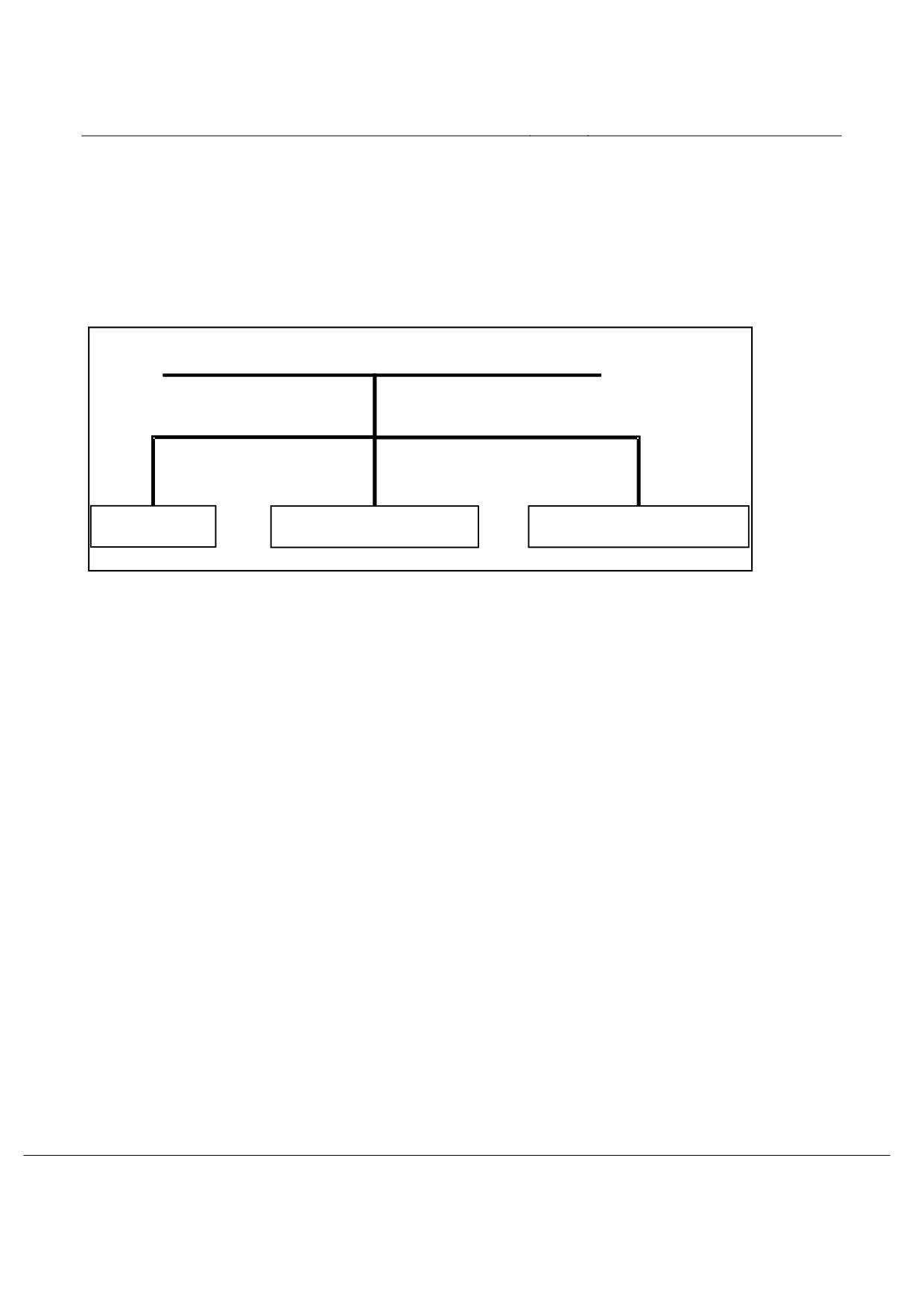
High-speed Maglev system
Maglev Technical Committee
Design principles
Guideway
Track switching equipment
General
The general designs/types of track switching equipment are shown in figure 110.
Track switching equipment
Switches
Traversers
Swinging platforms
Figure 110: Designs/types of track switching equipment
The use of the individual types of track switching equipment is dependent on the operational requirements.
These are divided into
(1)
Track switching equipment which does not require an interruption to the journey (switches
and transfer connections as combinations of switches) and
(2)
Track switching equipment which requires an interruption to the journey (transfer tables,
swinging platform),
Switches in a turning off position can be ridden over at various speeds depending on the geometry (bending
line) (normal arrangement: Slow travel switch and quick travel switch, see /MSB AG-FW TRAS/). Transfer
connections which make the switch to a track which runs parallel possible can be realised through a combi-
nation of switches (see /MSB AG-FW TRAS/).The track switching equipment is normally made up of the
following principal groups:
- Guideway superstructure (e.g. bendable supports with horizontal beams and abutments);
- Positioning elements (normally electro mechanical propulsion systems);
- Locking devices;
- Air gap bypasses;
- Sensor technology and control;
- Energy supply;
- Switchgear areas;
- Guideway equipment.
Title
High-speed Maglev system design principles
Guideway Part I - Overriding requirements
Doc.no.:
57284
Version
White paper
Issue date
15.02.2007
Page 57
High-speed Maglev system
Maglev Technical Committee
Design principles
Guideway
Functional requirements
The following functional requirements are to be taken into account with regard to the operational safety (in-
corporation into the operational control systems) and availability:
(1)
The track switching equipment must make a secure, reliable switch of track possible for vehi-
cles and special vehicles.
(2)
The information about the status “track switching equipment can be travelled over safely” is
needed by the operational control systems BLT for testing.
For this purpose the track switching equipment must make the required signals available for
the systems control technology.
(3)
After reaching a secure end position the track switching equipment must retain its safe end
position regardless of failures in the sensor technology, monitoring or energy supply.
(4)
The design of the track switching equipment must ensure that it is not possible to leave the
secured end position without clearance by the systems control technology.
(5)
The failure of an individual electrical, electronic or electromechanical assembly in positioning
or locking devices, control, monitoring or current supply must remain without effect on the
ability to adjust and the correct message about the condition (safe end position) and the posi-
tion of the track switching equipment on the systems control technology.
(6)
The correct message about the condition (safe end position) and the position of the track
switching equipment (e.g. straight ahead position) must come to the systems control tech-
nology in the case of failure of an individual mechanical assembly too.
(7)
A diagnostic device for online diagnosis is to be integrated.
(8)
A device for adjustment of the track switching equipment on site is to be provided (on site
adjustment operation).
Design requirements
(1)
The interchange of the design is to be taken into account back in the planning phase if the
service life of the track switching equipment does not correspond to the service life of the
section of line.
(2)
The time cost for the exchange of modules/components of the track switching equipment
must correspond to the operational boundary conditions. Prescriptions regarding this must
occur in a project specific way.
(3)
The project specific adjustment times to be prescribed must be taken into account in the di-
mensioning of the propulsion elements.
(4)
The control and monitoring must make it impossible for the support safety and serviceability
of the track switching equipment or their components and modules to be affected adversely
as a result of incorrect function of individual actuating drives (e.g. through monitoring of syn-
chronised operation). The actions from the incorrect function are to be included in the verifi-
cation process of the track switching equipment.
Title
High-speed Maglev system design principles
Guideway Part I - Overriding requirements
Doc.no.:
57284
Version
White paper
Issue date
15.02.2007
Page 58
High-speed Maglev system
Maglev Technical Committee
Design principles
Guideway
(5)
The devices for adjusting and locking of the track switching equipment are to be constructed
with robust and error tolerant modules which are as low maintenance as possible.
(6)
An interruption free supply of current is to be guaranteed for the securing of the track switch-
ing equipment.
(7)
All modules/components are to be developed/integrated in such a way that the maintenance
expenditure is kept to a minimum.
(8)
In order to achieve high availability of the track switching equipment, functional redundancy
of the propulsion systems is to be attained.
(9)
The guideway substructures of at-grade track switching equipment consist of foundation with
elements for supporting and locking the horizontal beams.
(10)
The guideway substructures of elevated track change devices consist of foundation, supports
and support head plates with elements for supporting and locking the horizontal beams.
(11)
The static system of track switching equipment is to be defined dependent on the static and
system technical requirements (e.g. bending line). The prescription of the static system re-
quires proof of the compatibility with the complete system.
(12)
The routing technical requirements of the track switching equipment are set down in /MSB
AG-FW TRAS/.
(13)
The requirements of the geometry of the function levels are set down in /MSB AG-FW GEO/.
(14)
Mountings are to be equipped with stop/anti derail devices and bolts for removal of the sup-
porting forces and these devices are to keep the track switching equipment reliably in the re-
quired position while taking all actions from operation and environment into account.
(15)
Short guideway elements (abutment; L ≥ 1,032 m) are to be used as intermediate elements
between the moving guideway superstructures of the track switching equipment and the
guideway superstructures of the connecting guideway or the moving end of connecting track
switching equipment. The modules for locking and if appropriate gap filling are to be inte-
grated into these abutments.
(16)
The most robust possible products are to the used for the modules and components of the
track switching equipment.
(17)
In order to guarantee fault free winter operation, snow and ice sensitive control equipment is
to be heated and protected against collection and compression of snow where appropriate.
(18)
Rain water is generally to be drained off in such a way that icing up between moving parts
can be ruled out.
(19)
The structure of the control of the track switching equipment and the structure of the inter-
faces for securing the track switching equipment are to be defined project specifically in
agreement with the operational control systems. Suitable installation spaces are to be pro-
vided.
(20)
The control and monitoring of the control and locking equipment (for coming to the position
given by the systems control technology) usually occurs at the instigation of the systems con-
trol technology). A device for manual adjustment of the track switching equipment is to be
provided.
(21)
Buildings (if appropriate areas in existing buildings) which are to be as uniform as possible
are to provided very close to the track switching equipment for the control, safety and current
supply devices.
Title
High-speed Maglev system design principles
Guideway Part I - Overriding requirements
Doc.no.:
57284
Version
White paper
Issue date
15.02.2007
Page 59
High-speed Maglev system
Maglev Technical Committee
Design principles
Guideway
These buildings form part of the periphery of the track.
(22) For returning of the cable of the long stator winding from the mobile to the fixed switch end,
suitable holding fixtures are to be provided.
(23) It is recommended that there is a possibility of illuminating track switching equipment. For
elevated track change devices the fitting of a work surface (e.g. grating) under the continu-
ous girders can be effective. Both help to speed up maintenance measures during breaks in
operation.
(24) The compatibility of the horizontal gap developing at the mobile switch end (to the adjacent
guideway) with the requirements of the complete system is to be proved.
Title
High-speed Maglev system design principles
Guideway Part I - Overriding requirements
Doc.no.:
57284
Version
White paper
Issue date
15.02.2007
Page 60
High-speed Maglev system
Maglev Technical Committee
Design principles
Guideway
Verification process
The overriding requirements indicated in chapter 0 concerning the guideway verification process are gener-
ally to be observed.
The following requirements are to be given particular attention:
(1)
Particular attention in the testing and commissioning of track switching equipment must be
aimed at the proof of incorporation of the track switching equipment into the systems control
technology.
(2)
The adherence of the required transition times for each installed track switching device is to
be proved.
(3)
The frequency of adjustment to be taken as a basis for the dimensioning is to be prescribed
specifically for the project.
(4)
Instructions for the required reliability of the modules/components (e.g. MTBF values) must
occur in a project specific way.
(5)
The electrical power required for operation of the track switching equipment is to be estab-
lished in a project specific way for the dimensioning of the energy supply.
(6)
In track switching equipment, verification of the correct position of the maglev specific guide-
way equipment for each possible operating condition which may be observed (e.g. branching
off or straight ahead positions at switches) must be provided.
Handling, transport and assembly
(1)
For the appropriate transport and error free assembly of the track switching equipment in-
structions are to be created.
Title
High-speed Maglev system design principles
Guideway Part I - Overriding requirements
Doc.no.:
57284
Version
White paper
Issue date
15.02.2007
Page 61
High-speed Maglev system
Maglev Technical Committee
Design principles
Guideway
Special structures
Tunnels
General
The standards for tunnels are to be taken from /MSB AG-GESAMTSYS/
Primary load bearing elements
General
Under the term „primary load bearing element” all structures are included which hold the guideway super-
structure as an interim construction in the place of the usual guideway substructures and whose loads drain
off via its own foundation into the ground. Generally primary load bearing elements are used in order to
bridge large spans (e.g. valley bridges).
Functional requirements
(1)
The functional requirements of the primary load bearing elements correspond to the require-
ments of the guideway substructures (see chapter (2)).
(2)
In addition the consideration of location and/or project specific requirements for holding indi-
vidual modules of the line periphery may be required.
Design requirements
(1)
The required holding of elements/modules of the other guideway equipment or line periphery
is to be prescribed in a project specific way with verification of compatibility with the complete
system.
(2)
The necessity of providing gangplanks for the evacuation of people and other rescue devices
is to be prescribed individually as a function of the project specific safety and operating de-
sign.
(3)
For primary support elements in two stage or multi stage construction the fixed bearing is to
be arranged in the central primary support element area.
(4)
With large spans the gaps which occur at the crossing to the next guideway are to be defined
in such a way by measures which are to be defined in a project specific way that the value
limits given in /MSB AG-FW BEM/ und /MSB AG-FW GEO/ are not exceeded. Essentially
here the temperature related shifts and/or deformations on the primary load bearing element
in x and y direction and the various settlements in direction z with regard to the subsequent
guideway are to be taken into account.
(5)
The project specific requirements for winter service are to be adhered to (e.g. falling snow
when clearing intersection areas).
Verification process
The overriding requirements indicated in chapter 0 concerning the guideway verification process are gener-
ally to be observed.
The following requirements are to be given particular attention:
Title
High-speed Maglev system design principles
Guideway Part I - Overriding requirements
Doc.no.:
57284
Version
White paper
Issue date
15.02.2007
Page 62
High-speed Maglev system
Maglev Technical Committee
Design principles
Guideway
(1)
The dynamic behaviour of the primary load bearing element is to be verified.
(2)
Settlements, expansion gaps and changes in incline at the crossing to the next guideway are
to be shown.
(3)
The requirements and serviceability are to be proved by measurements on commissioning
the system achieved. The scope is to be agreed with the inspectorate.
(4)
The theoretical assumptions applied for the calculations of the deviations in the geometry of
the function levels (between primary load bearing element and subsequent guideway) result-
ing from different structure temperatures are to be verified metrologically.
Handling, transport and assembly
For appropriate transport and error free fitting of the individual components and modules on the
primary load bearing element, project specific instructions are to be created.
Title
High-speed Maglev system design principles
Guideway Part I - Overriding requirements
Doc.no.:
57284
Version
White paper
Issue date
15.02.2007
Page 63
High-speed Maglev system
Maglev Technical Committee
Design principles
Guideway
Edge of line
General
The edge of the line includes
(1)
system technically required small structural appliances which are used in the environment
close to the route (e.g. radio mast, power houses) and
(2)
other required structures which follow the guideway in their position (e.g. noise insulation
wall, visual protection, deviation protection etc).
The edge of the line also includes e.g.:
- Power houses of the propulsion system;
- power houses of the track change devices;
- radio masts;
- cable channels;
- enclosures;
- impact protection structures;
- noise protection structures;
- sight protection structures;
- supporting walls, troughs.
Functional requirements
The functional requirements of the appliances of the edge of the track result from their tasks and are thus
individually different.
The appliances must however all be made in such a way that they
(1)
reliably meet all requirements during the required service life at project specific operating and
environmental conditions (such as e.g. the requirements as a result of aerodynamic actions,
vibrations, consideration of the natural vibration behaviour) and
(2)
have no inadmissible effects on operation.
Design requirements
(1)
The design requirements of the modules/components at the edge of the track are to be pre-
scribed specifically for the project.
(2)
For components at the edge of the track, verification of compatibility with the complete sys-
tem is to be given.
This also relates to the arrangement of the components and modules in planning in particu-
lar.
Title
High-speed Maglev system design principles
Guideway Part I - Overriding requirements
Doc.no.:
57284
Version
White paper
Issue date
15.02.2007
Page 64
High-speed Maglev system
Maglev Technical Committee
Design principles
Guideway
Verification process
(1)
The verification for the appliances at the edge of the track are to be made in line with the
state of technology with possible maglev railway specific actions being taken into account.
(2)
The overriding requirements indicated in chapter 0 concerning the guideway verification
process are generally to be observed.
Handling, transport and assembly
(1)
For the individual appliances at the edge of the track, instructions for handling, transport and
assembly are to be created if this is not yet prescribed in the design planning. This can be
done without in the case of reliable ancillary components/modules.
Title
High-speed Maglev system design principles
Guideway Part I - Overriding requirements
Doc.no.:
57284
Version
White paper
Issue date
15.02.2007
Page 65
High-speed Maglev system
Maglev Technical Committee
Design principles
Guideway
Quality management and quality assurance
General
A comprehensive quality assurance is required in all phases from the planning up to the manufacture and
use of the guideway in order to able to assure adherence to the guideway standards.
These phases are:
- Development;
- Planning (outline/design planning of the routing and structures);
- Verification process (design and qualification);
- Manufacture (production, equipment, transport and assembly);
- Commissioning and testing;
- Maintenance (inspection, servicing, repair).
The measures for assuring the required quality of the guideway are to be set down in a comprehensive qual-
ity management system (QS) - following DIN ISO 9000ff. This system must take all aspects of quality assur-
ance into account and is to be agreed by the supplier with the responsible inspection bodies directly after the
start of the project (e.g. in the form of test specifications, test instructions or work instructions).
The supplier/manufacturer must use quality management and quality assurance to ensure that
(1)
adherence to the system technical and safety technical requirements is assured, verified and
documented in terms of development and manufacture. The aim of the quality assurance is
to ensure and document the adherence to the minimum requirements by testing the required
verifications. This is the prerequisite for the orderly integration of the guideway subsystem
into the complete system.
(2)
the relevant quality documentation is made available for his scope of supply.
(3)
the project dependent quality risks are analysed and suitable measures are prescribed indi-
vidually.
The analysis should occur before the start of the project and in coordination between the
subsystems (guideway, vehicle, propulsion/energy supply and systems control technol-
ogy)and the responsible inspectorate and building manager. For this all interfaces of the
guideway subsystem are to be balanced with those of the other subsystems.
(4)
an assessment and if appropriate an adaptation of the prescribed measures is carried out at
intervals to be prescribed (e.g. at the end of individual project phases) or when unexpected
circumstances arise.
(5)
the results of the quality assurance are documented in a suitable form (test reports, result
records etc), comprehensibly archived and made available in a suitable form for maintenance
and later use.
(6)
the use of the guideway can take place in line with the project specific requirements.
Title
High-speed Maglev system design principles
Guideway Part I - Overriding requirements
Doc.no.:
57284
Version
White paper
Issue date
15.02.2007
Page 66
High-speed Maglev system
Maglev Technical Committee
Design principles
Guideway
In detail it is recommended that
(1)
all required standards are specified.
(2)
the required design regulations and methods are stated and matched to the project engineer-
ing and technologies.
(3)
Methods, processes and tools are prescribed and used in order to prove that all standards
were verified (e.g. through analysis, examination, testing, design review, audit).
(4)
there is a prescribed qualification standard for each module/component which makes it pos-
sible to show that the unit is laid out and designed in such a way that it reliably fulfils all pro-
ject specific standards for operation and environment.
(5)
the design is producible and repeatable and the resultant product can be verified and used
within the operational limits given.
(6)
appropriate monitoring measures for acquiring components, materials, software and hard-
ware elements and services are taken.
(7)
Manufacture, integration, testing and maintenance are demonstrably carried out in such a
way that the end product matches the valid configuration.
(8)
a monitoring system for non conformities is introduced and maintained so that they can be
followed up systematically and their recurrence can be prevented.
(9)
quality notes are made and analysed in order to record and report trends punctually for pre-
ventative and corrective measures.
(10) all required testing equipment and tools for checking, measuring and testing the mod-
ules/components are available and they are regularly calibrated in order to assure their accu-
racy.
(11) Processes and instructions for marking, separating, handling, packing, preserving, storing
and transporting of all modules/components are introduced.
Verification of the guideway with regard to
compatibility to the complete system
The verification of compatibility of the components and modules of the guideway to the complete system
must be planned and carried out in a project specific way.
The responsibility for this lies with the supplier of the guideway or the respective component or module.
The verification helps to assure serviceability (availability, ability to maintain, functionality) of the respective
component/module for use within the complete system and also assures the function of the complete system
when using the respective component/module.
The verification of compatibility with the complete system includes testing of adherence to the system techni-
cal minimum requirements
(1)
of development and design documents.
Title
High-speed Maglev system design principles
Guideway Part I - Overriding requirements
Doc.no.:
57284
Version
White paper
Issue date
15.02.2007
Page 67
High-speed Maglev system
Maglev Technical Committee
Design principles
Guideway
(2)
for the routing (dynamic handling test, geometrical routing test, test of the distribution of sup-
ports and linked to this the maglev specific guideway equipment).
(3)
for project specific planning and design documents including the planned arrangement of the
guideway equipment and edge of the track.
(4)
for manufacturing and assembly processes.
(5)
for the modules and components realised for the guideway.
(6)
for the measurements to be defined project specifically (e.g. noise, ride comfort, aerodynam-
ics, vibrations, interaction of guideway/vehicle).
For the testing of adherence to the system technical minimum requirements on modules and com-
ponents which have been completed, the following verifications must be provided at the very least:
(7)
Verification of quality assurance in the factory (e.g. geometrical checking of guideway
beams);
(8)
Verification of carrying out the interim inspection of the guideway following fine positioning as
a prerequisite for clearance for use with guideway bound special vehicles (and the subse-
quent on site installation of the guideway equipment);
The interim inspection of the guideway must include the following at the very least:
- the establishment of positive results of the quality tests of the materials or components in
the framework of the building design;
- a visual test which includes components which are hard to access with emphasis placed
on the supporting and load discharging components and modules (e.g. supports, cantile-
ver arm);
- the documentation of the test and all deviations established from the desired state.
(9)
Verification of the carrying out of the final system technical inspection of the guideway follow-
ing completed installation of the guideway equipment as a prerequisite for clearance for rid-
ing with vehicles;
The final system technical inspection must include the following at the very least:
- the establishment and documentation of the rectification of all shortcomings and damage
and deviations from the planning documents;
- the geodesic three dimensional recording of the space curve of the routing with devia-
tions from the desired state (if this has not occurred in connection with the assembly);
- the geodesic three dimensional recording of the position of the foundations (if this has not
occurred in connection with the assembly);
- the verification of adherence to the system technical minimum requirements (in accor-
dance with /MSB AG-FW ÜBG/ and /MSB AG-FW GEO/);
- the documentation of the test and all deviations established from the desired state;
- the documentation of the results of an examination which may be repeated after elimina-
tion of deviations.
Title
High-speed Maglev system design principles
Guideway Part I - Overriding requirements
Doc.no.:
57284
Version
White paper
Issue date
15.02.2007
Page 68
High-speed Maglev system
Maglev Technical Committee
Design principles
Guideway
The final system technical inspection serves to establish the “zero condition” (condition of the guideway be-
fore commissioning). This condition is the basis for the assessment of the effects of all changes which occur
later.
Following this test and following commissioning of the vehicles, the reference runs of the automated meas-
urement systems must be carried out within a short period of time and these must be assigned to the geo-
desic measurement data.
The measures demanded in this chapter are required from a system technical viewpoint. They
form part of the total acceptance test.
In the course of creating the components, tests and inspections carried out can be assessed as
part of the building supervisory acceptance if it can be assumed that there have not been any sig-
nificant changes in the meantime.
Title
High-speed Maglev system design principles
Guideway Part I - Overriding requirements
Doc.no.:
57284
Version
White paper
Issue date
15.02.2007
Page 69
High-speed Maglev system
Maglev Technical Committee
Design principles
Guideway
Documentation
General
The documentation of the guideway includes:
(1)
technical documents of the guideway components and modules;
(2)
documentation of the project specific boundary conditions;
(3)
technical documents on construction (including quality assurance documentation);
(4)
Documentation for guideway maintenance.
Verification process for modules/components
(1)
The stability verification (supporting stability, proof of material fatigue), serviceability verifica-
tion and the associated drawings are to be stated with the generally recognised rules of en-
gineering being taken into consideration. For electronic data processing supported verifica-
tion of stability the “guideline for stating and testing of electronic data processing supported
stability verification” /Ri-EDV-AP-2001/ applies.
Project specific requirements
The project specific boundary conditions (requirements and instructions) for the guideway are to be pre-
scribed in a project specification for the guideway.
This specification is to contain at least the following:
(1)
project specific supplementation of the guideway design basis;
(2)
project specific system technical guideway equipment list;
(3)
Maintenance plan/programme for the guideway with an interface to the overriding mainte-
nance plan/programme of the complete system;
(4)
Definitions for guideway equipment (position and coding of the reference rails, position and
arrangement of the stator packs and arrangement of the motor winding, definition of the ar-
eas with external on-board energy supply);
(5)
Definition of the stopping places;
(6)
Creation of a top and limiting velocity from guideway dimensioning;
(7)
Examinations of the actions from the environment (e.g. of snow and ice on the minimum gra-
dient height and/or crossings of the infrastructure).
Technical documents for construction
Title
High-speed Maglev system design principles
Guideway Part I - Overriding requirements
Doc.no.:
57284
Version
White paper
Issue date
15.02.2007
Page 70
High-speed Maglev system
Maglev Technical Committee
Design principles
Guideway
The technical documents for construction must contain design documents and verification of mod-
ules/components of the guideway and neighbouring structures (graphic representation of the component with
corresponding uniformity, serviceability verification, verification of dynamic strength etc) and also the follow-
ing in particular:
(1)
Documents for appliances on the edge of the track and structures on the edge of the track
(with regard to the adherence to system technical requirements);
(2)
Documents on transitions between special structures/special designs and the standard
guideway (with regard to the adherence to the system technical requirements);
(3)
Documents on interfaces of the guideway with stations and stops (to assure adherence to
the system technical requirements);
(4)
Documents for design of the complete lightning protection and earth system including all in-
accessible cables and connections within the guideway superstructures and substructures;
(5)
Quality assurance programmes of the guideway manufacturer to realise a guideway (proce-
dure to ensure that the system technical and safety technical requirements are adhered to);
(6)
results of quality assurance in the factory (e.g. geometrical checking of guideway beams in
the factory);
(7)
results of fine positioning;
(8)
Routing (layout, gradients, banking);
(9)
Maintenance programmes for the individual components and modules of the guideway;
(10) Documents about add ons on the guideway in the project specific system technical guideway
equipment list.
System technical guideway equipment list
In the framework of the design planning a system technical guideway equipment list is to be created.
This document is to contain at least the following information in rising kilometres for each track:
- Track data (space curve, ranges, radius, banking, gradient height over ground etc);
- Substructures (with component numbering, location reference to space curve, and infor-
mation about special structures, track switching equipment and mass spring systems);
- Beams (with component numbering, location reference to space curve, information on the
exact system length of the beam and support arrangement);
- Stator pack arrangement (for each beam with information about the nominal gap on the
beam crossing, type indication of the used stator packs and complemented with module
arrangement if appropriate);
- phase related position of the motor winding (in relation to the use of the stator packs) and
definition of the cable entries and exits (in relation to the substructures);
- the guideway modules of the location system with location reference to the position of the
motor winding (e.g. arrangement and coding of the support reference strips);
- Stopping place areas;
Title
High-speed Maglev system design principles
Guideway Part I - Overriding requirements
Doc.no.:
57284
Version
White paper
Issue date
15.02.2007
Page 71