Design Principles High-speed Maglev System. Information (MSB, 2007) - page 7
High-speed Maglev system
Maglev Technical Committee
Design principles
Vehicle
• The rebound of the levitation chassis is considered separately in 0.
• Allowance is for the vertical rebound in the case of an unoccupied carriage body, taking into
account the dynamic displacements and the new state.
Additional vertical displacements fz
• Additional vertical displacements caused by a longitudinal and lateral inclination of the car-
riage body.
Lateral compression of one body side: deflection in phase on all levitation frames towards the
same guideway side. The displacements are covered in the chapter on rolling 0.
Longitudinal compression of one body end: deflection in phase on the opposite levitation frames of
the levitation chassis (pitching), e.g. in the event of failure of a pneumatic spring circuit.
Additional vertical displacement from the suspension gap control of the levitation chassis. The dis-
placements of the levitation chassis are taken into account in the kinematics of the levitation chas-
sis in Chapter 0.
Asymmetry γ0xz
• Asymmetry γ0xz is the static pitch angle of the carriage body as a result of offset of the load
in the longitudinal direction of the vehicle with a level guideway. The action is taken into ac-
count via the position of the carriage body centre of gravity.
WK
WK
∆y
WK
WK
∆yp8
∆yp8
∆yp1
∆yp1
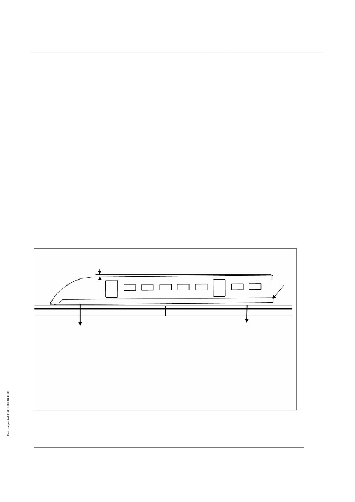
Figure 76: Vehicle kinematics - z-displacements / pitching of carriage body
Title
High-speed Maglev system design principles
Vehicle, Part III, Kinematic Gauge
Document
67650
Version
White Paper Issue date
15.02.2007
Page 27
no.:
High-speed Maglev system
Maglev Technical Committee
Design principles
Vehicle
Z-displacement / pitching load cases to be examined
• The highest z-level of the carriage body occurs with active pneumatic suspension (pressur-
ised pneumatic springs). If individual springs fail, the level is maintained by the level control;
negligible pitching occurs. The operational pitching is deduced taking into account the ac-
tive pneumatic spring system.
• The maximum pitching occurs for the “theoretically constructible” operating malfunction of a
depressurised pneumatic spring circuit.
• The design of the pneumatic spring circuits and the allocation of the springs to the pneu-
matic spring circuits must be such that the probability of occurrence of undue pitching is
negligible.
• The maximum pitch angles of a section occur for the case of an active pneumatic spring
circuit (z-level in the level recording point in nominal position) and a depressurised pneu-
matic spring circuit (z-level lowered on the settling springs). For information purposes, the
correlations for deduction of the pitch angle are included in the annex. The case of upward
rebound (pressure of pneumatic spring circuits above nominal pressure) is not considered
as, for this case, the pitch angle is clearly smaller compared to the stated malfunction situa-
tions and anyway is covered by the load case of empty weight or loading asymmetry.
• The pitch angle and the z-displacements of the carriage body may be calculated in ac-
cordance with Chapter 0.
Vehicle in nominal operation (two active pneumatic spring circuits) with max. z-level in accordance
with Chapter 0
Vehicle on depressurised pneumatic springs in accordance with Chapter 0 with minimum z-level
Vehicle in the case of malfunction with depressurised nose spring circuit in accordance with Chap-
ter 0 with maximum negative pitch angle (nose lowering)
Vehicle in the case of malfunction with depressurised rear spring circuit in accordance with Chap-
ter 0 with maximum positive pitch angle (rear lowering)
• The following cases must be examined:
Deflection/rebound of carriage body as a result of load states (empty weight, max. weight in accor-
dance with Chapter 0)
Vehicle running on guideway with vertical radius Rxz
Deflection/rebound of one end of carriage body as a result of starting / braking at maximum accel-
eration / deceleration
• The effect of crosswind and asymmetry γ0xz must be taken into account for the cases.
• In addition, the fault “lowering of one end of carriage body as a result of failure of a pneu-
matic spring circuit” must be assessed by the manufacturer, and a supplementary operating
measure, where necessary, must be defined.
• Only the end section has to be considered in all demonstrations. The middle sections are
covered by the demonstrations.
• The input parameters for deducing the pitch angle and z-displacements of the carriage
body are given in Chapter 0. Depending on the superimposition of load cases, the data to
Title
High-speed Maglev system design principles
Vehicle, Part III, Kinematic Gauge
Document
67650
Version
White Paper Issue date
15.02.2007
Page 28
no.:
High-speed Maglev system
Maglev Technical Committee
Design principles
Vehicle
be taken into account such as accelerations / decelerations to be assessed, carriage body
dimensions and asymmetries of the load are given in the chapter.
Y-displacement / yawing of carriage body
• The quasi-static yawing of the carriage body is considered on the basis of the secondary
suspension properties.
• The lateral displacements and/or the yawing of the carriage body depend on the suspen-
sion characteristics of the secondary suspension (gravity pendulum, arrangement of the y-
auxiliary springs).
• Characteristic quantity: Lateral displacement y, yaw angle δxy (see Figure 77).
Concepts regarding carriage body y-displacements / yawing
Yawing pivot point
• The pivot point is situated in the section coupling.
Geometric overthrow
Offset of a vehicle element caused by cornering
On the same side of the guideway centreline, it is assumed that all points in the same carriage body
cross-section have the same geometric overthrow (regarded as rigid body).
S projections
Offset of the vehicle end cross-sections caused by cornering
Asymmetry δ0xy
Asymmetry δ0xy is the static yaw angle of the carriage body as a result of offset of the load in the
longitudinal direction of the vehicle with a straight guideway. The action is taken into account via
the position of the carriage body centre of gravity.
Lateral displacements
The lateral displacement of the carriage body is made up of the following parts:
Geometric displacement caused by the vehicle position on a curve and on a straight track where
the vehicle vertical axis is located perpendicular to the guideway;
Quasi-static displacement y of the secondary suspension;
Quasi-static lateral displacement of the levitation chassis. The displacements of the levitation
chassis are taken into account in the kinematics of the levitation chassis in Chapter 0.
Title
High-speed Maglev system design principles
Vehicle, Part III, Kinematic Gauge
Document
67650
Version
White Paper Issue date
15.02.2007
Page 29
no.:
High-speed Maglev system
Maglev Technical Committee
Design principles
Vehicle
WK
WK
WK
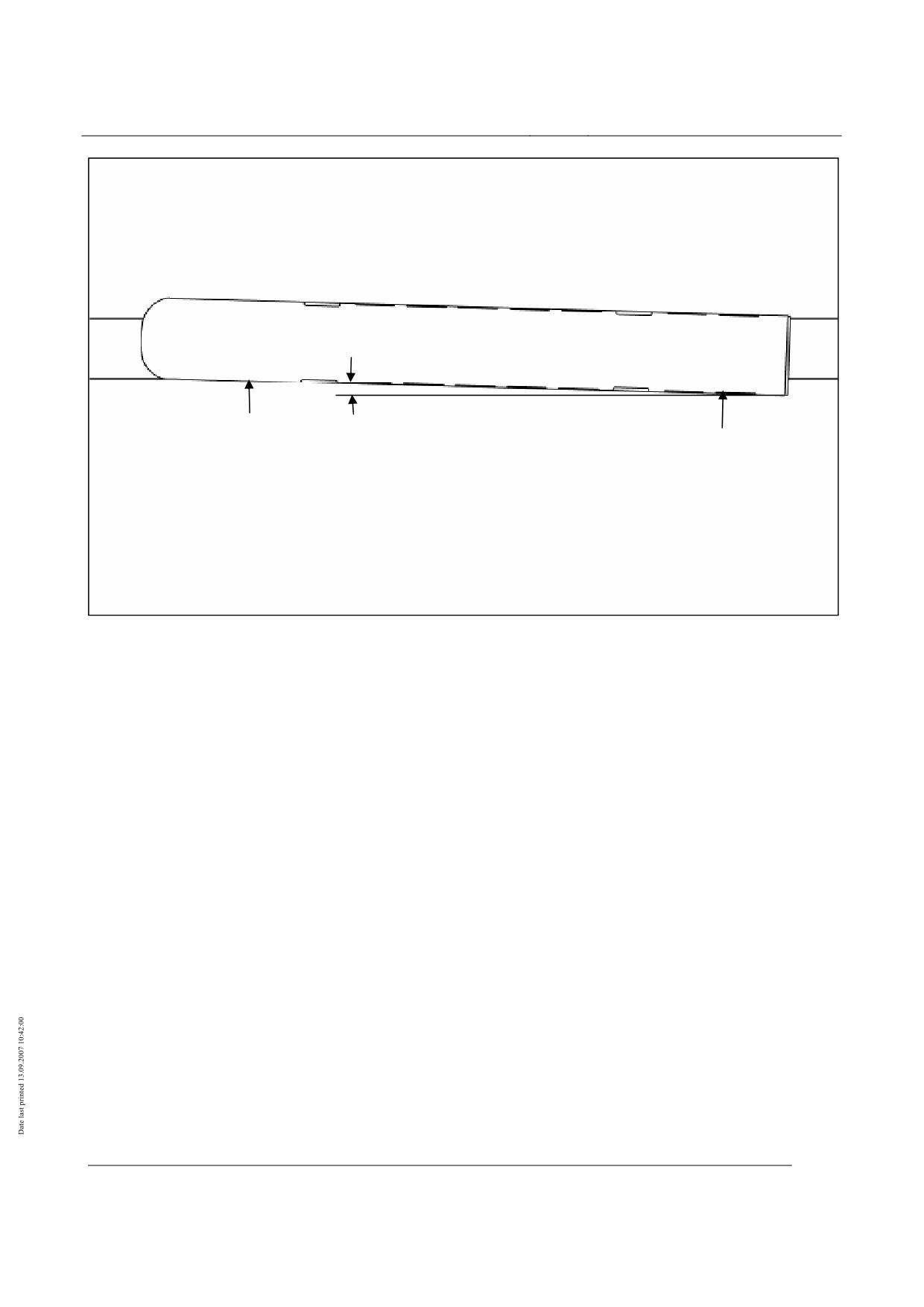
Figure 77: Vehicle kinematics - y-displacements / yawing of carriage body
Title
High-speed Maglev system design principles
Vehicle, Part III, Kinematic Gauge
Document
67650
Version
White Paper Issue date
15.02.2007
Page 30
no.:
High-speed Maglev system
Maglev Technical Committee
Design principles
Vehicle
Y-displacement / yawing load cases to be examined
• The yaw angle and y-displacements of the carriage body may be calculated in accor-
dance with Chapter 0.
• The following cases must be examined:
Vehicle runs on guideway with cant deficiency - displacement and yawing as a result of centrifugal
force
Vehicle runs on guideway with horizontal radius Rxy.
• The effect of crosswind and asymmetry δ0xy must be taken into account for both cases.
• The geometric overthrow and S projections when all displacements (carriage body and
running gear) are superimposed can be determined by means of suitable calculation meth-
ods (e.g. CAD models).
• The input parameters for deducing the yaw angle and y-displacements are given in Chapter
0. Depending on the superimposition of load cases, the data to be taken into account such
as guideway alignment, lateral accelerations to be assessed, carriage body dimensions,
asymmetries of the load and crosswind speeds are given in the chapter.
Title
High-speed Maglev system design principles
Vehicle, Part III, Kinematic Gauge
Document
67650
Version
White Paper Issue date
15.02.2007
Page 31
no.:
High-speed Maglev system
Maglev Technical Committee
Design principles
Vehicle
Kinematics between levitation chassis and guideway
• The statements in the sections of Chapter 0 must be taken into account.
Kinematic degrees of freedom of levitation
chassis
• The non-contact support and guidance allows the following rigid body degrees of freedom
of the levitation chassis:
z-displacement of levitation chassis through support gap control
y-displacement of levitation chassis through guidance gap control (track centre control)
rolling around the longitudinal axis caused by non-uniform support gap left/right (non-uniform z-
displacements)
pitching around the transverse axis caused by non-uniform support gap front/ rear (non-uniform z-
displacement),
yawing around the vertical axis caused by non-uniform guidance gap front/rear (non-uniform y-
displacement)
• In normal operation the relative movements of the levitation chassis to the guideway result
from the dynamic gap differences at the support and guidance magnets.
• The maximum displacements occur in the case of failures of the electromagnetic sup-
port/guidance system. These possible movements are limited as follows:
In the z-direction, upwards by minimum gap monitoring or, in borderline cases, by touching of the
support magnet on the stator, downwards mechanically by the support skid.
In the y-direction, mechanically by the track channel of the guidance magnets (start-up of guidance
magnet on lateral guide rail).
• The support and/or guidance gaps are measured at the position of the gap sensors.
• The following operating states must be taken into account:
Controlled settling of the whole vehicle in a standing position
Normal operation with support gap and track centre control
• In addition to the operating states, the following specific operating cases must be taken into
account:
Settling of individual support frames after failure of two dedicated support control circuits (local
mechanical support on support skid)
Failure of two dedicated guidance magnet control circuits (local mechanical guidance with guid-
ance magnet)
Controlled settling of the whole vehicle from low speed after automatic application of brakes with
eddy current brake
Uncontrolled settling on one side in the case of a short circuit in the propulsion coil
Title
High-speed Maglev system design principles
Vehicle, Part III, Kinematic Gauge
Document
67650
Version
White Paper Issue date
15.02.2007
Page 32
no.:
High-speed Maglev system
Maglev Technical Committee
Design principles
Vehicle
Displacements of levitation chassis
• The air gaps between levitation chassis and guideway are deduced below.
• These determine the possible displacements of the levitation chassis and their position in
relation to the guideway.
Support gap and support skid gap
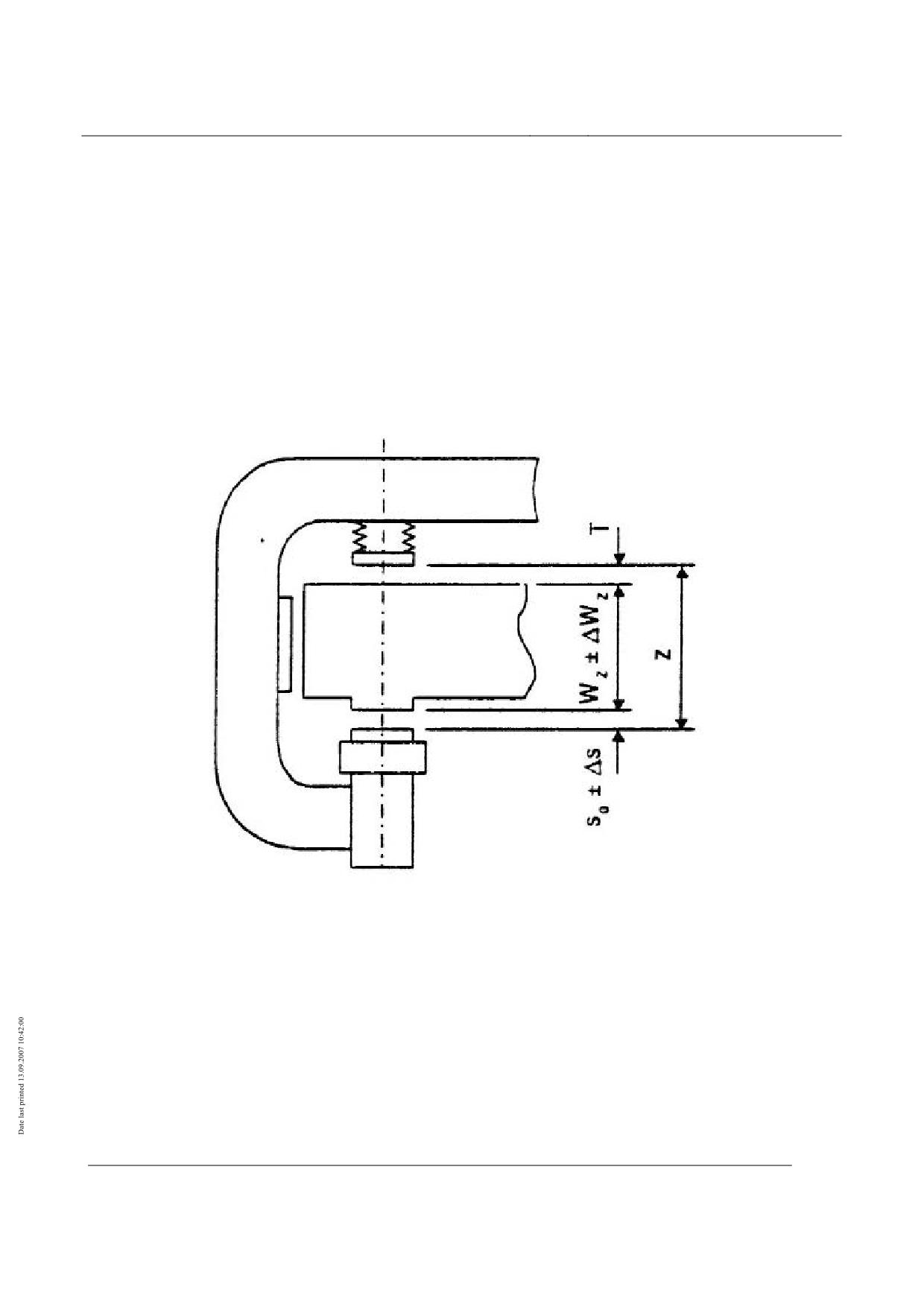
• In nominal state, the vehicle levitates at a defined support gap s0. Upward displacement of
the vehicle is limited by the support magnet resting on the stator surface, and downward
displacement by the contact of the support skid with the sliding surface.
•
Figure 78: Vehicle kinematics - Gap balance support (z-direction)
Title
High-speed Maglev system design principles
Vehicle, Part III, Kinematic Gauge
Document
67650
Version
White Paper Issue date
15.02.2007
Page 33
no.:
High-speed Maglev system
Maglev Technical Committee
Design principles
Vehicle
• Allowing for skid wear ∆V, the actual gripper dimension of the vehicle between the top of
the support magnet and the lower surface of the support skid is calculated generally to be
Z = Z0 ± ∆z + ∆fz + ∆V
Equation 1
• To demonstrate the loading gauge 0, the ∆Wz tolerances for the guideway are set at zero.
•
• For the levitated vehicle, the deflection/rebound of the levitation chassis and of the sup-
port magnet linkage must be taken into account if there is a deviation from the nominal
load.
∆fz = ∆fzG+∆fzTM
Equation 2
•
• For the settled vehicle, the rebound of the levitation chassis and the support magnet link-
age and the deflection of the support skid must be taken into account.
∆fz = ∆fzG+∆fzTM +∆fzTK
Equation 3
•
• The levitated vehicle is shown in nominal position in the construction documents.
• ∆fz= 0
•
• The support gap determines the maximum upward displacement of the levitation frame.
Allowing for the support dynamics in accordance with
• Figure 78, it amounts to
s = s0 ± ∆s
Equation 4
• For the tests, the gap s0 corresponds to the max. value for upward displacement.
•
• The support skid gap determines the maximum downward displacement of the levitation
frame. Allowing for the support dynamics in accordance with
• Figure 78, it amounts to
T = Z0 + ∆z + ∆V - Wz - (s0 ± ∆s )
Equation 5
•
Title
High-speed Maglev system design principles
Vehicle, Part III, Kinematic Gauge
Document
67650
Version
White Paper Issue date
15.02.2007
Page 34
no.:
High-speed Maglev system
Maglev Technical Committee
Design principles
Vehicle
Guidance gap
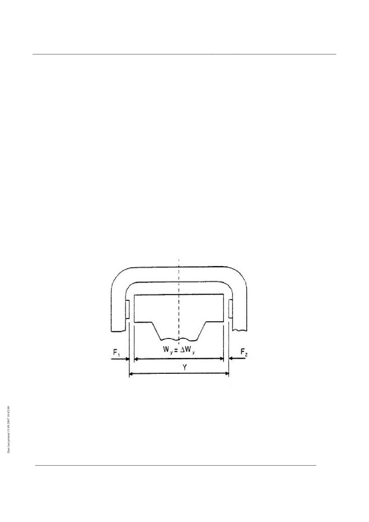
• In nominal state, the vehicle levitates at a defined guidance gap F. Lateral displacement of
the vehicle is limited in both directions ± by the guidance magnet resting on the lateral
guide rails of the guideway.
• With track centre control, the track gauge of the vehicle between the guidance magnets is
Y = Y0 ± ∆y - ∆fy
Equation 6
•
• For the levitated vehicle, deflection/rebound of the levitation chassis ∆fy occurs if there is a
deviation from the nominal load. This value can generally be disregarded.
• The maximum guidance gap occurs during mechanical guidance. The guidance magnet of
one side of the levitation frame rests on the lateral guide rail and is not subject to any force.
The opposite guidance magnet is subject to applied force.
• The vehicle gauge is then
YA = Y0 ± ∆y +∆P
Equation 7
Figure 79: Vehicle kinematics - Gap balance guidance (y-direction)
Title
High-speed Maglev system design principles
Vehicle, Part III, Kinematic Gauge
Document
67650
Version
White Paper Issue date
15.02.2007
Page 35
no.:
High-speed Maglev system
Maglev Technical Committee
Design principles
Vehicle
•
• P represents the maximum abrasion of the terminal strips.
• As it concerns a wear state defined as the most unfavourable, the wear should not be as-
sessed simultaneously for all guidance magnets. Therefore, the full wear is assessed only
for one vehicle side.
• ∆P = P
• Thus, the sum of both guidance gaps is calculated at
FAmax = Y0 + ∆y + P - Wy
Equation 8
• To demonstrate the loading gauge 0, the ∆Wy tolerances for the guideway are set at zero.
• For the side of the levitation frame resting on the guideway, the value of the displacement
of the levitation chassis from the nominal position is
• dy = FAmax - F
• where F corresponds to the nominal gap of the starting position.
•
• The reduction in the guidance gap during cornering in accordance with 0 can be taken into
account with radii of curve of < 1000 m.
•
Torsions of the levitation chassis
• The z- and y-displacements of the levitation chassis (support and guidance gap, support
skid gap) cause rolling, pitching and yawing of the levitation chassis.
• For the vehicle kinematic gauge, the unfavourable carriage body positions occur with the
onset of displacements (support and guidance gap).
• The pitch and yaw torsions reduce the displacements of the carriage body and do not have
to be taken into account.
• The rolling of the levitation chassis must be taken into account since the vehicle roll angle
increases.
Title
High-speed Maglev system design principles
Vehicle, Part III, Kinematic Gauge
Document
67650
Version
White Paper Issue date
15.02.2007
Page 36
no.:
High-speed Maglev system
Maglev Technical Committee
Design principles
Vehicle
Demonstration of the vehicle kinematic gauge
Guidance cross-sections
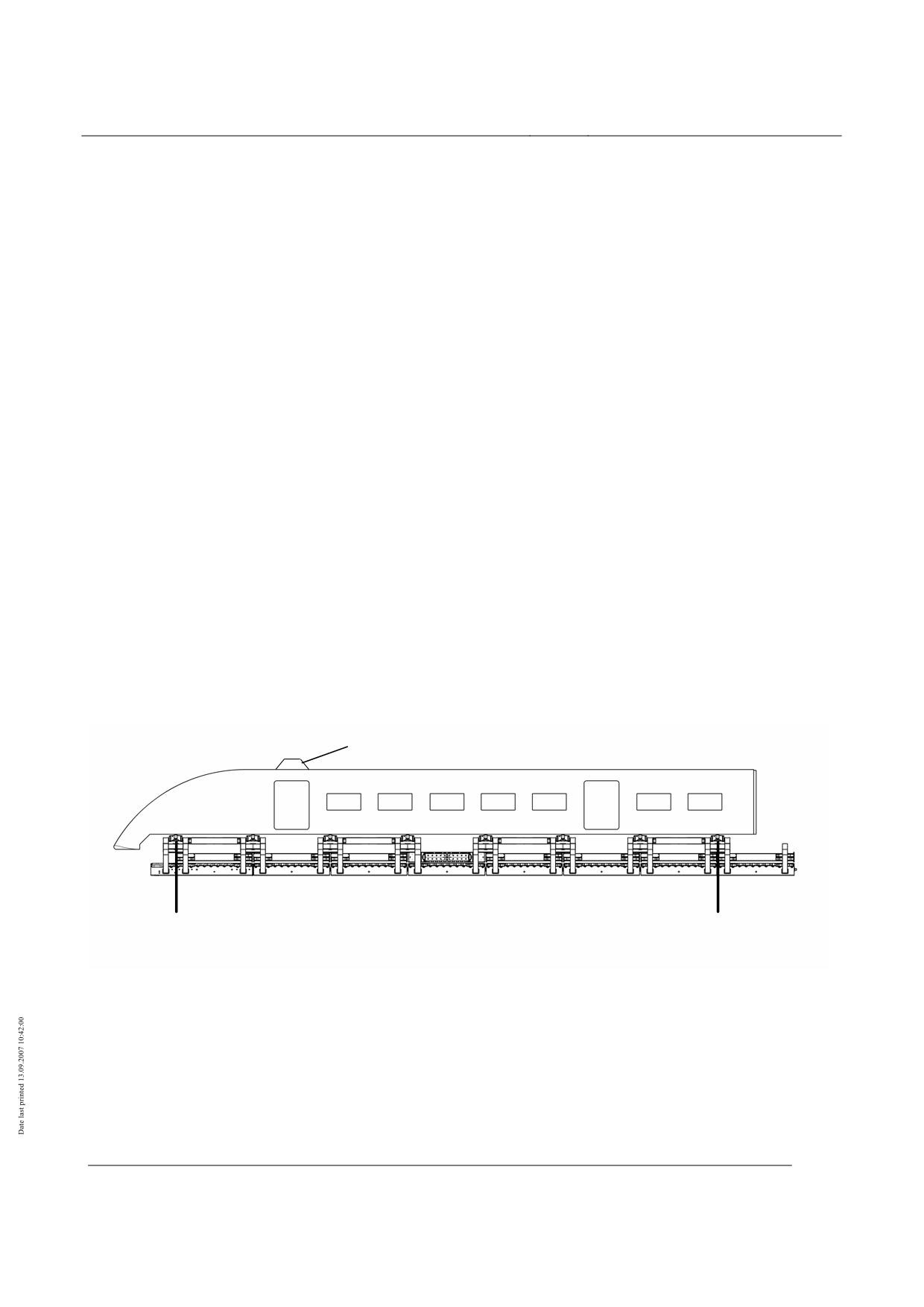
• The following statements regarding processing of the guidance cross-sections must be
taken into account:
• The adjustment of the vehicle in relation to the guideway is determined by means of the ve-
hicle cross-sections.
• Maglev vehicles have 4 levitation chassis per section.
• To demonstrate the kinematic gauge, the guidance cross-sections are located in the first
and last levitation chassis.
• The position of the carriage body in relation to the two levitation chassis is determined from
the position of the linkage consoles of the x-linkage of the carriage body (x- and y-position
centre of levitation chassis, y-position centre carriage body).
• The position of the two middle levitation chassis must be checked for this defined carriage
body position.
• The two middle chassis have a fixed relationship to the guideway and to the carriage body;
in terms of the guideway via the support and guidance gaps, in terms of the carriage body
via the pendulum (y- and z-displacements).
• If a geometric constraining condition occurs because of these chassis, the position of the
carriage body must be adjusted, otherwise the middle levitation chassis are disregarded.
Beispiel für Anbauteil: Funkantenne
Führungsquerschnitt 1
Führungsquerschnitt 2
Example of attachment: radio aerial
Guidance cross-section 1
Guidance cross-section 2
Figure 80: Positioning of vehicle on the guideway
Title
High-speed Maglev system design principles
Vehicle, Part III, Kinematic Gauge
Document
67650
Version
White Paper Issue date
15.02.2007
Page 37
no.:

High-speed Maglev system
Maglev Technical Committee
Design principles
Vehicle
Load cases / geometric situations to be con-
sidered
• As a minimum requirement, the operating load cases in accordance with Chapter 0 must be
demonstrated.
• The specific operating cases, see Chapter 0, must be examined by the manufacturer with
regard to possible effects. Any operational measures which may be required must be
named and must be agreed and laid down with the operator and the licensing authority.
Operating load cases
• The following table contains the load case combinations A to D of the running train which
have to be considered. In addition, the table shows which actions are superimposed when
determining vehicle kinematics. The actions to be taken into account in maintenance facili-
ties for demonstrating the kinematic gauge must be agreed with the operator.
•
Operating cases - vehicle kinematics
Case
A
B
C
D
Inertial forces from:
• Empty weight
X
X
X
X
• Maximum operational loading (1.3 times
maximum payload)
• Maximum deceleration / acceleration ax
X
X
X
X
X
X
• Maximum lateral acceleration ay
X
X
• Maximum vertical acceleration from
concave/convex transition curve az
• Asymmetry of the load
X
X
Alignment
• Vehicle on curved track
X
X
• Vehicle on straight track, concave/ con-
X
X
vex transition curve incl. vehicle move-
ment dynamics
Crosswind
• Crosswind acting constantly during operation
X
X
X
X
Table 77: Operating cases for vehicle dynamics
• The values to be assessed for wind speeds, weights and alignment as well as the asymme-
try of the load must be laid down on a project-specific basis. Superimposition of load cases
may also be laid down on a project-specific basis.
• Unless otherwise agreed for specific projects, the following values are applicable:
Alignment parameter in accordance with Chapter 0
The vehicle movement dynamics of the carriage body as a consequence of the guideway are to be
set as ∆z= ± 10mm (experimental value).
Title
High-speed Maglev system design principles
Vehicle, Part III, Kinematic Gauge
Document
67650
Version
White Paper Issue date
15.02.2007
Page 38
no.:
High-speed Maglev system
Maglev Technical Committee
Design principles
Vehicle
Operational crosswind vw = 10 m/s.
Title
High-speed Maglev system design principles
Vehicle, Part III, Kinematic Gauge
Document
67650
Version
White Paper Issue date
15.02.2007
Page 39
no.:
High-speed Maglev system
Maglev Technical Committee
Design principles
Vehicle
As the maximum levitation chassis displacements are not dependent on suspension character-
istics, a conservative assumption of an “extreme position” of the first levitation chassis is used
(guidance cross-section of the section nose in accordance with Chapter 0) with simultaneous
nominal position of the second levitation chassis (guidance cross-section of the section rear in ac-
cordance with Chapter 0). This method is sensible, as only the first or, where appropriate, last levi-
tation chassis is considered and the two middle levitation chassis in between are disregarded. If
these intervening middle chassis are taken into account, this produces smaller pitch and yaw an-
gles.
Levitation chassis position of guidance cross-section of nose:
The guidance magnets of the guidance-cross sections rest on the inside of the curve during
cornering; allowance is made for the operationally permissible wear on the terminal strips.
Two cases are distinguished for the z-position of the levitation frames:
a) the support magnet of the first chassis rests on the lower edge of the guideway (maxi-
mum pitch of carriage body caused by upward displacements of the levitation chassis)
b) taking into account the static deflection and the permissible operational wear, the sup-
port skid of the first chassis rests on the slide rail (maximum pitch of carriage body cau-
sed by downward displacements of the levitation chassis)
Levitation chassis position of guidance cross-section of rear:
• Nominal dimensions for support, guidance and skid gaps:
• Examples of gap dimensions:
Support gap
10 mm
Guidance gap
11 mm
Support skid gap
16 mm
• Examples of wear values:
Operational wear, and not the maximum possible wear, is assessed for the support skid
coatings and terminal strips. The wear parameters must be laid down on a project-
specific basis.
Skid coatings:
CFC:
1.5 mm
GKB 5:
5 mm
Terminal strips guidance magnet:
1.0 mm.
Title
High-speed Maglev system design principles
Vehicle, Part III, Kinematic Gauge
Document
67650
Version
White Paper Issue date
15.02.2007
Page 40
no.:
High-speed Maglev system
Maglev Technical Committee
Design principles
Vehicle
Specific operating cases
• The following cases should be assessed by the manufacturer as part of the examination of
malfunctions. The cases are not superimposed with other load cases. Worst-case load
cases: malfunctions in the sense of a marginal consideration, which can be disregarded on
the basis of the probability of their occurrence:
•
failure of individual pneumatic spring circuits
•
carriage body on settling springs (discharged pneumatic springs)
• Specific load cases: specified specific operating cases:
maximum crosswind 37 m/s
maximum carriage body load (evacuation case)
uncontrolled settling on one side in the event of winding short circuit
maximum support skid wear
• The maximum wear may be utilised only in the case of mechanical support of a levitation
frame, which counts as a specific operating case, as far as a stopping place to be laid down
on a project-specific basis (see also MSB AG-BLT, Chapter 6.3.3.1). Maintenance meas-
ures are carried out after occurrence of this event.
• The levitation chassis (guidance cross-sections) must be arranged in nominal position.
Title
High-speed Maglev system design principles
Vehicle, Part III, Kinematic Gauge
Document
67650
Version
White Paper Issue date
15.02.2007
Page 41
no.:
High-speed Maglev system
Maglev Technical Committee
Design principles
Vehicle
Annex (for information purposes)
Deduction of the kinematic degrees of freedom
of carriage body
Roll angle of carriage body
The pendular forces ∆Fpz from y-carriage body forces FyWk are calculated as
z
−
z
sWK C
∆F
= 0,5
⋅F
⋅
pz
yWK
y
p
Equation 9
where
FyWk = FySW + FmWKy
Equation 10
FmWKy = mWK ⋅ ay
Equation 11
The carriage body roll angle from crosswind and centrifugal forces ηyzFy occurs as
M
2⋅
∆F
⋅
y
z
−
z
T
pz
p
sWK C
η
=
=
=
F
⋅
yzFy
yWK
c
c
c
ηWK
ηWK
ηWK
z
−
z
sWK C
η
=(m
⋅a
+
F
)
⋅
yzFy
WK
y
ySW
c
ηWK
Equation 12
The carriage body roll angle from guideway canting ηyzα’ occurs with the rolling moment MTα’
M
=(z
−
z
)⋅sinα'⋅F
Tα
'
sWK
C
mWKz
where FmWKz = mWK ⋅ az
z-inertial force of carriage body
M
z
-
z
T
sWK C
=
=
F
⋅
⋅
sinα'
ηyzα
'
mWKz
c
c
ηWK
ηWK
M
z
-
z
T
sWK C
=
=
m
⋅a
⋅
⋅sinα'
ηyzα
'
WK
z
c
c
ηWK
ηWK
Equation 13
Title
High-speed Maglev system design principles
Vehicle, Part III, Kinematic Gauge
Document
67650
Version
White Paper Issue date
15.02.2007
Page 42
no.:
High-speed Maglev system
Maglev Technical Committee
Design principles
Vehicle
Z-displacements and pitch angle of carriage body
Active suspension
The z-pendular forces are deduced as follows for a 3-section vehicle on the basis of the 5 + 3 pneu-
matic spring interconnection of the end section. As the end section is relevant for the investigation,
the number of sections is of no importance. A change in the pneumatic spring interconnection requi-
res adjustment of the equations.
Statically defined, a carriage body is supported via two pneumatic spring circuits, with levitation
frames 1 to 5 of the end section (nose) being supplied by pneumatic spring circuit 1, and levitation
frames 6 to 8 of the end section and levitation frames 1 - 4 of the middle section by pneumatic
spring circuit 2. The pneumatic springs of a circuit have the same pressure p1 or p2 with the pendu-
lar forces FpzLF1 (pneumatic spring circuit 1) and FpzLF2 (pneumatic spring circuit 2).
On the basis of the installed pneumatic spring, the pendular force of the first suspension spring is
Fp1z = 0.5 ⋅ FpzLF1
nose levitation frame
Equation 14
The residual pendular forces occur at
Fpiz = FpzLF1
i = 2.5 end section
Equation 15
Fpiz = FpzLF2
i = 6.8 end section
Equation 16
Fpiz = FpzLF2
i = 1.4 middle section
Equation 17
The pendular forces FpzLF1 and FpzLF2 as well as the coupling force FKz are calculated via the system
of equations to be solved by means of determinants, for example.
A⋅
x=
b
at
⎡
18
28
0⎤
⎡F
⎤
⎡
2⋅F
+
F
⎤
pzLF1
zWKE
zWKM
⎢
⎢
⎥=
⎢
⎥
9
6
1⎥⋅
F
F
pzLF2
zWKE
⎢
⎥
⎢
⎥
⎢
⎥
⎣9
x
6
x
0⎦
⎣
F
⎦
⎣F
⋅
x
+
F
⋅
z
⎦
s1
s2
Kz
zWKE
sE
xWKE
sE
Equation 18
Title
High-speed Maglev system design principles
Vehicle, Part III, Kinematic Gauge
Document
67650
Version
White Paper Issue date
15.02.2007
Page 43
no.:
High-speed Maglev system
Maglev Technical Committee
Design principles
Vehicle
Nose pneumatic spring circuit depressurised
If the nose pneumatic spring circuit is depressurised, the carriage body end section is supported on
levitation frames 1 to 5 via the settling springs.
In deducing the pendular forces and the pitch angle, it is assumed that the residual pendular loads
are supported via the pneumatic suspension.
The forces of the settling springs in relation to the swing axle are
FpizE = cpiE ⋅ zpiE
For the pitch angle η, the distance xNiE from the settling springs to the assumed pitch pivot point of
the carriage body (level measuring point of the adjacent pneumatic spring circuit) gives a settling
spring deflection of
zpiE = tan η ⋅ xNiE
Equation 19
The pendular forces are calculated as
FpizE1 = cpiE ⋅ zpiE
i = 1.5 end section 1 (nose pneumatic
spring circuit depressurised)
Equation 20
FpizE1 = FpzLF2
i = 6.8 end section 1
Equation. 21
FpizM = FpzLF2
i = 1.4 middle section
Equation 22
Fp1zE2 = 0.5 ⋅ FpzLF1 nose levitation frame end section 2
Equation 23
FpizE2 = FpzLF1
i = 2.5 end section 2
Equation. 24
The pitch angle η, the pneumatic spring circuit forces FpzLF1 and FpzLF2 as well as the coupling forces
FKz1 (end section 1) and FKz2 (end section 2) are obtained by solving the following system of equa-
tions:
A⋅
x=
b
at
5
⎡
⎤
(c
⋅
x
)
9
28
0
0
⎢
∑
piE
NiE
⎥
i=1
⎡
tanη
⎤
⎡
2⋅F
+
F
⎤
⎢
⎥
zWKE
zWKM
5
⎢
⎥
⎢
⎥
⎢
⎥
F
F
⋅
x
+
F
⋅
z
(c
⋅
x
⋅
x
)
0
6⋅
x
0
0
pzLF1
zWKE
sE
xWKE
sE
∑
piE
NiE)
iE
s2
⎢
⎥
⎢
⎥
⎢
i=1
⎥⋅⎢
F
⎥
=
⎢
F
⎥
⎢
5
⎥
pzLF
2
zWKE
⎢
⎥
⎢
⎥
⎢
(c
⋅
x
)
0
6
1
0⎥
∑
piE
NiE
F
F
⎢
Kz1
⎥
⎢
zWKE
⎥
⎢
i=1
⎥
⎢
⎥
⎢
⎥
⎢
0
9
6
0
1⎥
F
F
⋅
x
+
F
⋅
z
⎣
Kz1
⎦
⎣
zWKE
sE
xWKE
sE
⎦
⎢
⎥
0
9⋅
x
6⋅
x
0
0
⎣
s1
s2
⎦
Equation 25
Title
High-speed Maglev system design principles
Vehicle, Part III, Kinematic Gauge
Document
67650
Version
White Paper Issue date
15.02.2007
Page 44
no.:
High-speed Maglev system
Maglev Technical Committee
Design principles
Vehicle
For non-linear characteristics ciE or cpiE, the system of equations must be solved iteratively, where
applicable.
Pneumatic spring circuit of E/M section junction depressurised
If the pneumatic spring circuit at the E/M section junction is depressurised, the carriage body end
section is supported on levitation frames 1 to 5 via the pneumatic springs of the nose pneumatic
spring circuit and the settling springs of levitation frames 6 to 8.
To deduce the pendular forces and the pitch angle, only the end section is considered. i.e. the sup-
port from the middle section is disregarded. The level recording point (z-displacement zero) is loca-
ted on levitation frame 2. This point is also the pivot point.
The forces of the settling springs in relation to the swing axle are
FpizE = cpiE ⋅ zpiE
For the pitch angle η, the distance xNiE from the settling springs to the assumed pitch pivot point of
the carriage body (level measuring point of the nose pneumatic spring circuit) gives a settling spring
deflection of
zpiE = tanη ⋅ xNiE
Equation 26
The pendular forces are calculated as
Fp1z = 0.5 ⋅ FpzLF1
nose levitation frame
Equation 27
Fpiz = FpzLF1
i = 2.5 levitation frames 2 to 5
Equation 28
FpizE1 = cpiE ⋅ zpiE
i = 6.8 (pneumatic spring circuit 2
depressurised)
Equation 29
The pitch angle η and the pneumatic spring circuit forces FpzLF1 are obtained by solving the follo-
wing system of equations:
A⋅
x=
b
at
8
⎡
⎤
9
[
c
⋅(
x
-
x
)
]
⎢
∑
iE
2E
iE
⎥
⎡F
⎤
⎡
F
⎤
i=6
pzLF1
zWKE
⎢
=
8
⎥⎢
⎥
⎢
⎥
2
tan
η
F
⋅
x
+
F
⋅
z
⎢
⎥
⎣
⎦
⎣
zWKE
sE
xWKE
sE
⎦
9⋅
x
[
c
⋅(x
⋅
x
-
x
)
]
s1
∑
iE
iE
2E
iE
⎣
⎦
i
=
6
Equation 30
Title
High-speed Maglev system design principles
Vehicle, Part III, Kinematic Gauge
Document
67650
Version
White Paper Issue date
15.02.2007
Page 45
no.:
High-speed Maglev system
Maglev Technical Committee
Design principles
Vehicle
All pneumatic spring circuits depressurised - support on settling springs
With pneumatic springs depressurised, the carriage body is supported exclusively on the settling
springs.
The forces of the settling springs in relation to the swing axle are:
FpizE = cpiE ⋅ zpiE
The pitch pivot point of the carriage body is located in the section coupling. The displacement z0 of
the section coupling gives the following values for the z-displacements of the settling springs:
zpiE = zK + ∆zpiE
Equation 31
and with the distance xiE from the settling springs to the section coupling the pitch angle η is
z
piE
η = arctan
x
iE
Equation 32
The pendular forces are calculated as
FpizE1 = cpiE ⋅ zpiE
end section
Equation 33
The pitch angle η and the static basic deflection zK are obtained from the following system of equa-
tions:
A⋅
x=
b
at
8
4
8
⎡
⎤
c
+
c
(c
⋅
x
)
⎢
∑
piE
∑
piM
∑
piE
iE
⎥
⎡
z
⎤
⎡
0,5F
+
0,25F
⎤
i=1
i=1
i=1
0
zWKE
zWKM
⎢
⎥⋅
=
8
8
⎢
⎥
⎢
⎥
2
tanη
0,5(F
⋅
x
+
F
⋅
z
)
⎢
⎥
⎣
⎦
⎣
zWKE
sE
xWKE
sE
⎦
∑
(
c
piE
⋅
x
iE
)
∑
(c
piE
⋅
x
iE
)
⎣
⎦
i
=1
i
=1
Equation
34
Title
High-speed Maglev system design principles
Vehicle, Part III, Kinematic Gauge
Document
67650
Version
White Paper Issue date
15.02.2007
Page 46
no.:
High-speed Maglev system
Maglev Technical Committee
Design principles
Vehicle
Y-displacements and yaw angle of carriage body
The y-pendular loads and the yaw angle of the carriage body can be deduced analogously to the z-
pendular loads and the pitch angle. Similarly, a 5 + 3 pneumatic spring interconnection of the end
section is taken as the basis.
Y-auxiliary springs are arranged at levitation frames 2 and 3 and also at 6 and 7, parallel to the pen-
dulums.
As has already been stated, if the pneumatic spring interconnection and/or the arrangement of the y-
auxiliary springs are changed, it is necessary to adjust the equations.
The static basic displacement in a lateral direction is y0; this corresponds to the
y-displacement of the section coupling yK.
The additional y-displacement from yawing ∆yi for the levitation frames i = 1.8 results from the
yaw angle δxy
∆y
i
tan
δ
=
xy
x
ZFi
Equation 35
The y-displacement of the points of application of the end-section pendulum is
ypi = yK + ∆yi
where i = 1.8
Equation 36
The pendular forces are calculated at
y
pi
F
=
⋅F
piy
piz
l
p
i = 1.8
Equation 37
The forces at the y-auxiliary spring are obtained from the correlation
FZFiy = cZF⋅ypi
Equation 38
The yaw angle δxy and the static basic deflection yK are obtained from the following system of equa-
tions:
A⋅
x=
b
where
8
x
iE
f
=
2
(F
⋅
)+c
⋅(x
+
x
+
x
+
x
)
1
∑
pizE
ZF
2E
3E
6E
7E
i=1
l
p
8
2
x
iE
2
2
2
2
f
=
2
(F
⋅
)+c
⋅(x
+
x
+
x
+
x
)
2
∑
pizE
ZF
2E
3E
6E
7E
l
i=1
p
Title
High-speed Maglev system design principles
Vehicle, Part III, Kinematic Gauge
Document
67650
Version
White Paper Issue date
15.02.2007
Page 47
no.:
High-speed Maglev system
Maglev Technical Committee
Design principles
Vehicle
8
4
2
2
f
3
=
∑
F
pizE
+
∑
F
pizM
+6⋅
ZF
l
p
i=
1
l
p
i=
1
8
2
f
=
(
F
⋅
x
+
c
+
x
⋅(x
+
x
+
x
+
x
))
4
∑
pizE
iE
ZF
2E
2E
3E
6E
7E
l
p
i
=1
⎡
f
f
⎤
⎡
y
⎤
⎡
F
⋅x
+
F
⋅
x
⎤
1
2
0
yWKE
sE
ySWE
SWE
⋅
=
⎢
⎥
⎢
⎥
⎢
⎥
f
f
tanδ
F
+0,5F
+
F
+
,
F
⎣
3
4
⎦
⎣
xy
⎦
⎣
yWKE
yWKM
ySWE
ySWM
⎦
Equation 39
Guidance gap correction for curved guideway
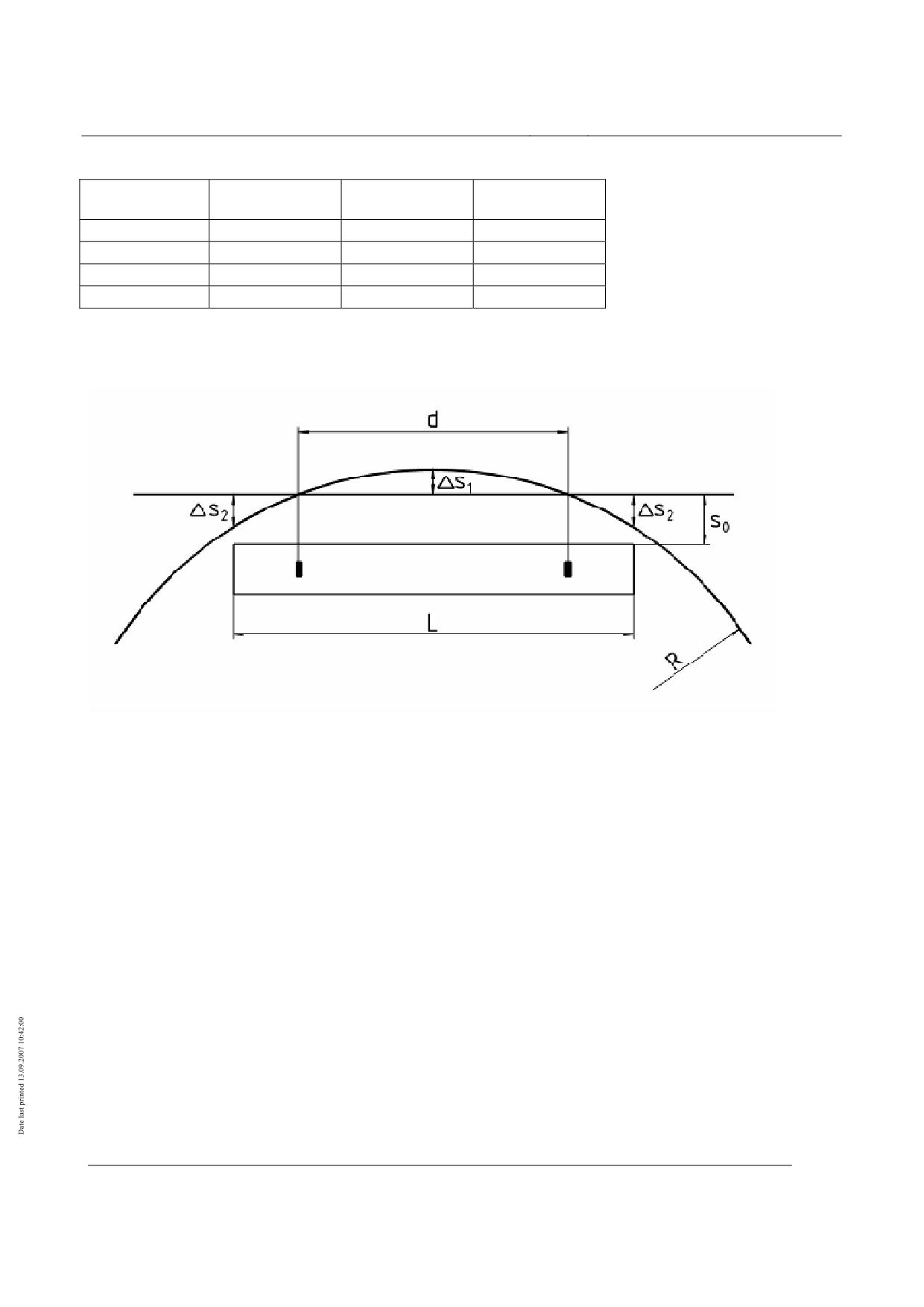
In a curved guideway, location-dependent deviations in the actual air gap compared to the set gap
occur over the magnet length as a result of the curvature of the lateral guide rail. The size of this
deviation depends on the radius of curve R and on the position of the gap sensors (distance d). The
guideway curvature reduces the free air gap. In accordance with Figure 81 the set air gap occurs at
the measuring position of the gap sensors; between the sensors the air gap is reduced by ∆s1, and at
the magnet end it increases by ∆s2. The gap ∆s1 is relevant.
The cumulative gap on cornering is
FR = ∆s1 + ∆s2
Equation 40
2
⎛
L
⎞
2
FM
F
=
R
−
R
−
⎜
⎟
R
⎝
2
⎠
Equation 41
The gap difference at the centre of the guidance magnet is calculated at
2
2
⎛d
⎞
∆s
=
R
−
R
−
⎜
⎟
1
⎝
2
⎠
,
Equation 42
The gap difference at the end of the guidance magnet is calculated at
∆s2 = FR - ∆s1
Equation 43
Correction values for a designed magnet length LTM = 3050 mm and a sensor distance of approx.
2300 mm.
Title
High-speed Maglev system design principles
Vehicle, Part III, Kinematic Gauge
Document
67650
Version
White Paper Issue date
15.02.2007
Page 48
no.:
High-speed Maglev system
Maglev Technical Committee
Design principles
Vehicle
Radius
FR
∆s1
∆s2
[m]
[mm]
[mm]
[mm]
350
3,3
1,8
1,5
1000
1,2
0,7
0,5
2000
0,6
0,3
0,3
Straight track
0
0
0
Table 78: Effect of radius of curve on guidance magnet air gap
Figure 81: Guidance gap correction for cornering
Title
High-speed Maglev system design principles
Vehicle, Part III, Kinematic Gauge
Document
67650
Version
White Paper Issue date
15.02.2007
Page 49
no.:
High-speed Maglev system
Maglev Technical Committee
Design principles
Vehicle
High-speed Maglev system
Design principles
Vehicle
Part IV
Levitation and guidance systems
Title
High-speed Maglev system design principles
Vehicle, Part IV, Levitation and guidance systems
Document
73388
Version
White Paper Issue date
15.02.2007
Page 1
no.:
High-speed Maglev system
Maglev Technical Committee
Design principles
Vehicle
All rights reserved
Title
High-speed Maglev system design principles
Vehicle, Part IV, Levitation and guidance systems
Document
73388
Version
White Paper Issue date
15.02.2007
Page 2
no.:
High-speed Maglev system
Maglev Technical Committee
Design principles
Vehicle
Distribution
The Vehicle Committee has released this document for publication.
Title
High-speed Maglev system design principles
Vehicle, Part IV, Levitation and guidance systems
Document
73388
Version
White Paper Issue date
15.02.2007
Page 3
no.:
High-speed Maglev system
Maglev Technical Committee
Design principles
Vehicle
Revisions
Date of release: 15.02.2007; White Paper, Vehicle Committee.
Title
High-speed Maglev system design principles
Vehicle, Part IV, Levitation and guidance systems
Document
73388
Version
White Paper Issue date
15.02.2007
Page 4
no.:
High-speed Maglev system
Maglev Technical Committee
Design principles
Vehicle
Contents
Distribution
3
Revisions
4
Contents
5
General
8
Purpose and applications
8
High-speed MAGLEV railway general specifications
8
Abbreviations and Definitions
9
Legislation, regulations, standards and directives
9
Identification and mandatory nature of requirements
9
Definitions (vehicle-specific)
10
General specifications for the levitation and guidance system
13
Operation
13
Design and ratings
13
Safety requirements
14
General
14
Requirements for the on-board energy supply
14
Requirements for the execution of a set-down command
16
Systematic faults in the magnet control equipment
16
Maintenance of the safety characteristic of magnet control circuits
16
Lightning overspill
17
ESD
17
Requirements for the assemblies of the levitation and guidance system
18
Structural assemblies of the levitation and guidance system
18
Chassis structure and panelling
18
Carriage body pivot / secondary suspension
18
Magnet pivot
20
Support skid
20
Functional assemblies of the levitation and guidance system
21
Levitation function
21
Guidance function
23
On-board energy supply
24
Safety-relevant control / supervision
26
Title
High-speed Maglev system design principles
Vehicle, Part IV, Levitation and guidance systems
Document
73388
Version
White Paper Issue date
15.02.2007
Page 5
no.:
High-speed Maglev system
Maglev Technical Committee
Design principles
Vehicle
Actions of the levitation and guidance system on the guideway
27
General
27
Types and combinations of actions
27
Characteristic values and load arrangements
28
General
28
Vehicle self weight and payload
29
Quasi-static loads from driving dynamics
30
Quasi-static loads from side wind (without lift)
30
Quasi-static loads from restoring forces in small radius curves
32
Loads from driving and braking with the long stator
33
Maximum loads at the support magnet - stator pack interface
33
Maximum loads at the support magnet - lateral guidance rail interface
37
Maximum loads at the support skid - sliding surface interface
40
Title
High-speed Maglev system design principles
Vehicle, Part IV, Levitation and guidance systems
Document
73388
Version
White Paper Issue date
15.02.2007
Page 6
no.:
High-speed Maglev system
Maglev Technical Committee
Design principles
Vehicle
List of figures
Fig. 1: Side view and cross-section (showing the principle)
10
Fig. 2: Magnet module (example)
11
Fig. 3: Levitation / Guidance magnets (Example)
11
Fig. 4: Support skid (example)
12
Fig. 5: Typical curve for stat pz ± ∆ stat pz
29
Fig. 6: Typical curve for py, SW where vFzg= 400 km/h and SW = 37m/s
31
Fig. 7: Typical curve for py, ZWG
32
Fig. 8: Typical load arrangement for support magnet without technical faults and breakdowns
(Example)
35
Fig. 9: Typical load arrangement for support magnet in the event of a support magnet circuit failure
(Example)
36
Fig. 10: Typical load arragements of guidance magnets (example)
40
List of tables
Table 1: Summary of vehicle loading conditions
28
Table 2: Characteristic static line loads of the vehicle (averaged)
29
Table 3: Actions resulting in side wind on the vehicle
31
Table 4: Maximum local constraining force
32
Table 5: Driving and braking forces with the long stator
33
Table 6: Maximum support magnet load
34
Table 7: Maximum line loads
37
Table 8: Maximum impact force
38
Table 9: Maximum support skid forces
40
Title
High-speed Maglev system design principles
Vehicle, Part IV, Levitation and guidance systems
Document
73388
Version
White Paper Issue date
15.02.2007
Page 7
no.:
High-speed Maglev system
Maglev Technical Committee
Design principles
Vehicle
General
Purpose and applications
This "High-speed magnetic levitation railway vehicle design principles, part IV - levitation and
guidance systems" sets out the requirements for the traction and driving systems of the high-speed
MAGLEV system vehicles that do not depend on the project concerned.
This design principles applies to a Maglev system in accordance with the General Maglev System
Act /AMbG/.
Part IV is to be used for the specification, execution and certification of the levitation and guidance
system of Maglev vehicles and covers:
• Definition of the levitation and guidance system,
• Requirements for the functions of the levitation and guidance system,
• The actions of the levitation and guidance system on the guideway.
High-speed MAGLEV system design principles
This document is part of the documentation for high-speed magnetic levitation railways consisting
of a number of design principles. Figure 1 /MSB AG-GESAMTSYS/ shows the documentation tree.
The overall design principles for the complete system and its appendices apply uniformly to all the
documentation:
•
High-speed MAGLEV system design principles, complete system, Document no.: 50630,
/MSB AG-GESAMTSYS/, with appendices:
•
Annex 1: Abbreviations and definitions, Document no.: 67536, /MSB AG-
ABK&DEF/
•
Annex 2: Legislation, regulations, standards and directives, Document no.: 67539,
/MSB AG-NORM&RILI/
•
Annex 3: Environmental constraints, Document no.: 67285, /MSB AG-UMWELT/
•
Annex 4: Operating rules (operation and maintenance), Document no.: 69061, /MSB
AG-BTR/
•
Annex 5: Noise, Document no.: 72963, /MSB AG-SCHALL/
The documentation on the vehicle consists of the following documents:
•
High-speed Maglev system design principles, vehicle, Part I.: Design principles, Document
no.: 67698, /MSB AG-FZ GEN/
•
High-speed Maglev system design principles, vehicle, Part II.: Design, document no.:
67694, /MSB AG-FZ BEM/
•
High-speed Maglev system design principles, vehicle, Part III.: Kinematic limits, Document
no.: 67650, /MSB AG-FZ KIN/
Title
High-speed Maglev system design principles
Vehicle, Part IV, Levitation and guidance systems
Document
73388
Version
White Paper Issue date
15.02.2007
Page 8
no.:
High-speed Maglev system
Maglev Technical Committee
Design principles
Vehicle
•
High-speed Maglev system design principles, vehicle, Part IV.: Levitation and guidance
systems, Document no.: 73388, /MSB AG-FZ TRAFÜ/
•
High-speed Maglev system design principles, vehicle, Part V.: Braking system, Document
no.: 73389, /MSB AG-FZ BREMS/
Abbreviations and Definitions
The abbreviations and definitions supplied in /MSB AG-ABK&DEF/ should be used.
Legislation, regulations, standards and directi-
ves
The prescriptive documents listed in /MSB AG-NORM&RILI/ contain definitions that are referred
to in the high-speed Maglev system design principles and have become part of the high-speed
Maglev system design principles. Where prescriptive documents in /MSB AG-NORM&RILI/ are
dated, subsequent changes or revisions of these publications do not apply. Where references are
undated, the latest edition of the prescriptive documents referred to is applicable.
The edition of the standards and guidelines to be adhered to in a Maglev project must be made bind-
ing for each specific project.
Identification and mandatory nature of requi-
rements
The content of the present document is substantially based on the provisions of /DIN 820/ .
In the following chapters of this document, and in the appendices,
•
Requirements are shown in standard type
•
Explanations, guidelines and examples are shown in italic.
Where notes on project-specific regulations are given in this document for individual cases, (e.g. in
a specification or a contractual regulation) this means that the manufacturer and the contractor
must consult the approvals authorities and come to an agreement.
Title
High-speed Maglev system design principles
Vehicle, Part IV, Levitation and guidance systems
Document
73388
Version
White Paper Issue date
15.02.2007
Page 9
no.:
High-speed Maglev system
Maglev Technical Committee
Design principles
Vehicle
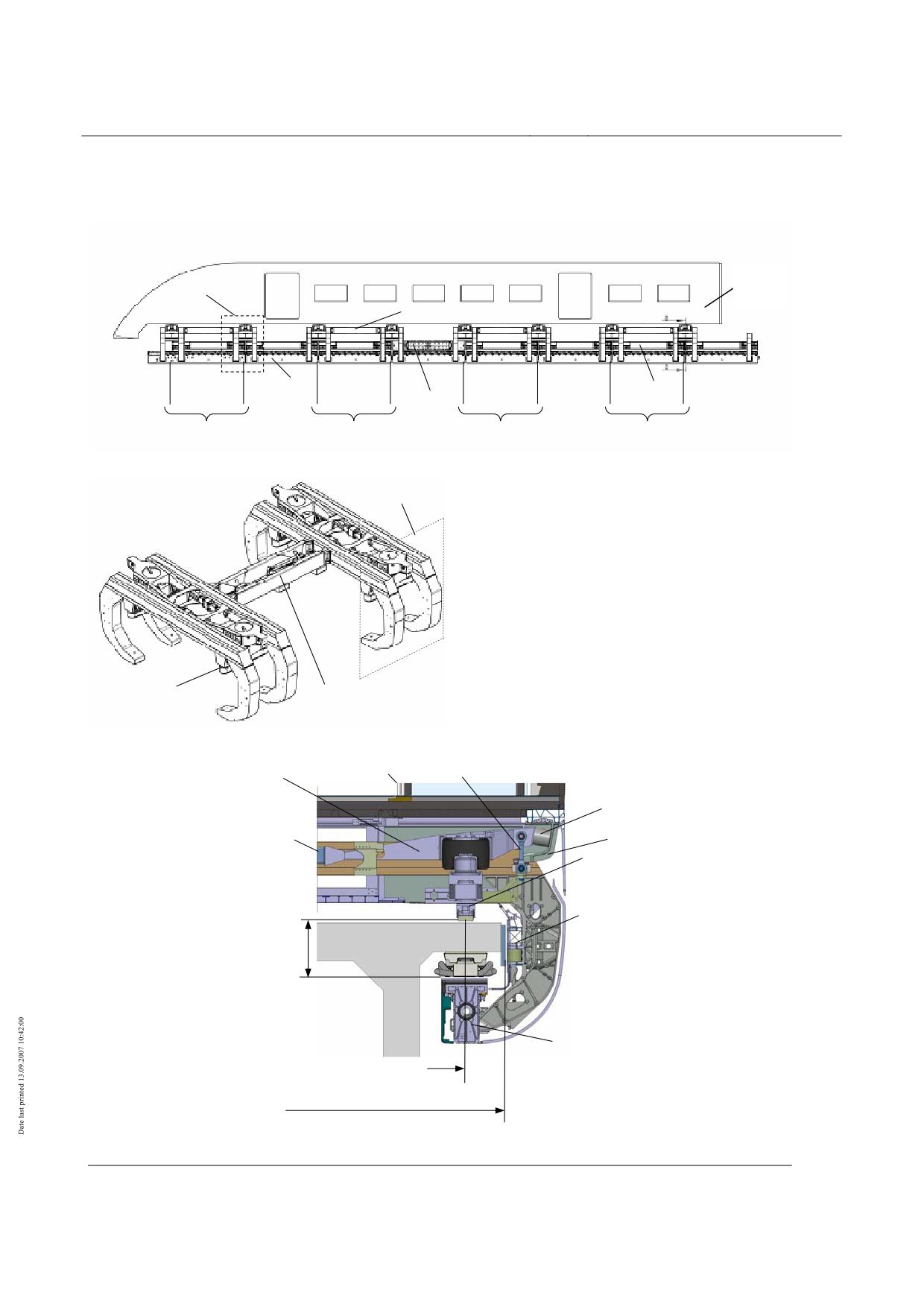
Definitions (vehicle-specific)
WK
SR
∆y
Longitudinal connector
TM
FM
BM
1
2
3
4
5
6
7
8
SG1
SG2
SG3
SG4
Levitation chassis
(without magnets)
SR
SG
= Levitation chassis
SR
= Levitation undercarriage
(2 levitation frames + connecting parts)
TM = Support magnet
FM = Guidance magnet
BM = Braking magnet
TK = Support skid
WK = Carriage body
TK
Longitudinal connector
Pneum. spring
Pendulum
Pneumatic spring
Additional Y spring
Z support for carriage body
Roll stabiliser
TK
FM
Vehicle
frame dimen-
TM
Support magnet centre distance =
support skid centre distance
Vehicle guideway width
Fig. 82: Side view and cross-section (showing the principle)
Title
High-speed Maglev system design principles
Vehicle, Part IV, Levitation and guidance systems
Document
73388
Version
White Paper Issue date
15.02.2007
Page 10
no.:
High-speed Maglev system
Maglev Technical Committee
Design principles
Vehicle
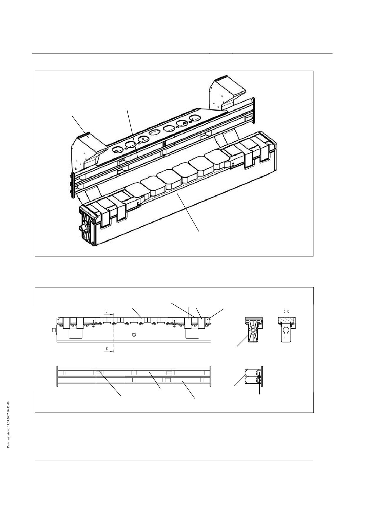
Guidance magnet
Levitation frame
Support magnet
Fig. 83: Magnet module (example)
Levitation
High core pole
Main pole
clearance
Support magnet
End pole
Rear of mag-
net
Rear of mag-
Guidance magnet
GM coil
Pole bar
net
Guidance clearance
Guidance clearance
measuring unit
measuring unit
Fig. 84: Levitation / Guidance magnets (example)
Title
High-speed Maglev system design principles
Vehicle, Part IV, Levitation and guidance systems
Document
73388
Version
White Paper Issue date
15.02.2007
Page 11
no.:
High-speed Maglev system
Maglev Technical Committee
Design principles
Vehicle
Housing
Sliding surface
lining
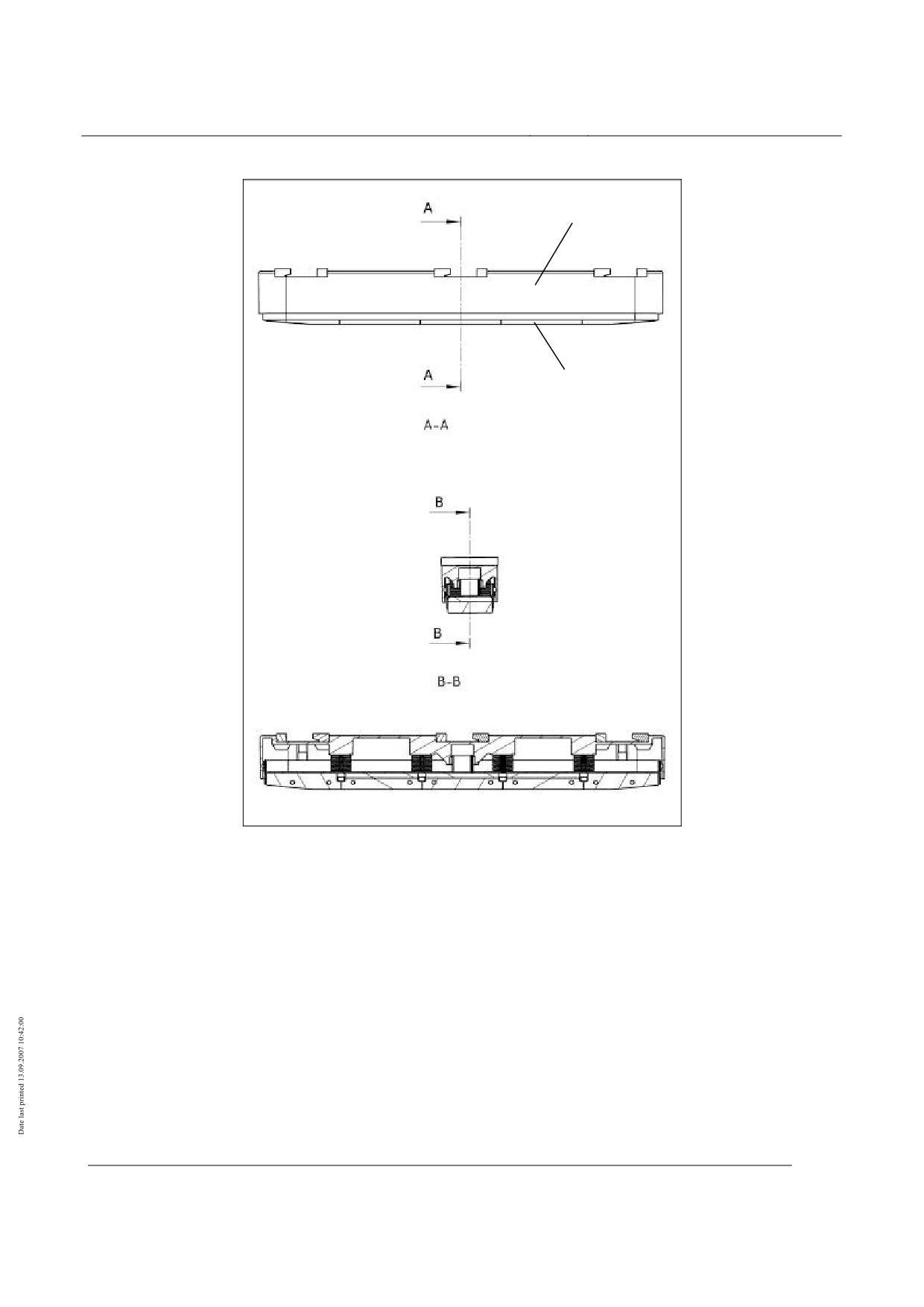
Fig. 85: Support skid (example)
Title
High-speed Maglev system design principles
Vehicle, Part IV, Levitation and guidance systems
Document
73388
Version
White Paper Issue date
15.02.2007
Page 12
no.:
High-speed Maglev system
Maglev Technical Committee
Design principles
Vehicle
Design principles for the levitation and guidance system
Operation
See description in /MSB AG-GESAMTSYS/.
The levitation and guidance system of the Maglev vehicles must perform the following functions
over the whole of the specified speed and distance ranges:
• Magnetic support and guidance by means of controlled stored levitation and guidance magnets.
• Mechanical support using support skids in accidental situations or breakdowns or when the ve-
hicle is standing (set down), for frequency compare /MSB AG-FZ BEM/, chapter 8.
• Mechanical guidance, e.g. using sliding elements on the guidance magnets in the event of rare
technical faults or breakdowns and in accidental operating situations
(superimposition of the actions of extreme operating situations).
In tight curves (RH < 600 m) it may be necessary to limit the speed in order to have freedom of
movement.
Design
The loads that are borne by the structural components and pivots of the levitation and guidance sys-
tem must be determined using /MSB AG-FZ BEM/ and taken into account in their design.
These loads must be documented in a specification (Design loads).
Proof of load-bearing capability (general stress certificate) and fatigue resistance according to the
requirements set out in /MSB AG-FZ BEM/ must be provided for the components that transfer the
load.
Determination of the clearance between the support magnets and the stator pack, between the guid-
ance magnets and the lateral guidance rails and between the support skids and sliding surface must
take account of structural tolerances, load-dependent deformation, relevant operational influences
(e.g. route, speed, wear on the sliding surface lining, etc.) and environmental conditions and must
be documented in a clearance statement.
Title
High-speed Maglev system design principles
Vehicle, Part IV, Levitation and guidance systems
Document
73388
Version
White Paper Issue date
15.02.2007
Page 13
no.:
High-speed Maglev system
Maglev Technical Committee
Design principles
Vehicle
Safety requirements
The levitation and guidance system, consisting of the magnetic and mechanical equipment, must
conform to the safety requirements as per §19, /MbBO/.
General
The levitation and guidance function must be executed so that it is safe for all of its service life.
This property must be proven by means of a safety certificate to /EN 50126/. The safety certificate
is based on a risk analysis. The risk analysis must include the following elements:
• Description of the levitation and guidance system and the protective functions,
• Description of the assemblies participating in the levitation and guidance system, their func-
tions, connections and actions on each other,
• Identification of assemblies and functions that are responsible for safety.
Information on methods of performing the risk analysis is given in /prEN 50126-2/ and /prR009-
004/.
The requirements for and tests on the structural assemblies of the levitation and guidance system
are given in chapter 0.
The requirements for and tests on the functional assemblies of the levitation and guidance system
are given in chapter 0.
The SIL level according to /EN 50129/ for the electronic equipment of the levitation and guidance
system must be determined on the basis of the risk analysis and must be taken into account when
performing the hardware certification.
The level of the safety requirements for the software in the levitation and guidance system that has
been determined on the basis of the risk analysis must be taken into consideration when performing
the certification to /EN 50128/.
Possible faults must be identified using a suitable analysis and must be taken into account in the
safety certificate.
A suitable analysis must include consideration of at least the following faults:
• Fault in the on-board energy supply,
• Untimely execution of a set-down command,
• System failure (of software or hardware).
Certification of the lifetime safety of the levitation and guidance system must be performed using a
suitable method of analysis before the system is commissioned. The theoretical certificate must be
verified after the start of operation by evaluating the life cycle data of the assemblies.
Requirements for the on-board energy supply
Title
High-speed Maglev system design principles
Vehicle, Part IV, Levitation and guidance systems
Document
73388
Version
White Paper Issue date
15.02.2007
Page 14
no.:
High-speed Maglev system
Maglev Technical Committee
Design principles
Vehicle
The specifications for the on-board energy supply can be found in the specifications for the levita-
tion and guidance system, the safe brake and the other vehicle systems that are relevant to safety.
The following information applies to the levitation and guidance system.
The availability of the on-board energy supply as a whole must be guaranteed to match the require-
ments of the safety design (e.g. Failure of the collector rail power from more than one subnetwork),
if, as a consequence of this, the vehicle should be wholly or partly set down or the safe brake should
fail.
Since it is not possible to prevent individual faults in electrical systems with sufficient certainty,
there is an inevitable requirement for redundancy, i.e. the number of independent and electrically /
mechanically separate networks provided for each section must be sufficient to ensure that one
faulty network does not affect the remaining networks and the levitation and guidance function is
maintained.
To increase availability, these networks should be potential-free, i.e. without a direct electrical con-
nection to the vehicle chassis, so that they do not switch off in the event of a short-circuit.
Furthermore equipment must be provided to guarantee the required performance from the mains to
maintain the levitation and guidance function (e.g. batteries) and to guarantee that the vehicle levi-
tates and brakes safely once it has started off (see also/MSB AG-BLT/, chapter 6.3.3.1 and chapter
6.3.3.3).
The possible untimely switching off of all networks that are needed to maintain the levitation and
guidance function and the braking function during a mission, e.g. by triggering a central shutdown
command, must be prevented by means of a suitable technical device. A shutdown command must
only be effective when the vehicle is stationary and set down.
Faults and failures in the shutdown control must not lead to an unwanted shutdown. If the shutdown
command becomes ineffective as a result of a fault or failure it must still be possible to shut the
vehicle down. Access to the corresponding shutdown equipment must be obstructed in such a way
that only trained operators can actuate the shutdown.
The following must be taken into account:
Evidence that a failure of the on-board energy supply is sufficiently unlikely is deemed to be pro-
vided if the on-board energy supply has been certified in accordance with chapter 0 and the follow-
ing certificates are available:
1) Adequate redundancy
Adequate redundancy means that the number of separate independent electric and mechanical
networks is such that in spite of increasing network failure there is still enough on-board power
available to maintain the functions of levitation and guidance according to the specifications of
the safety system.
2) Electrical and mechanical separation of networks
Networks are deemed to be electrically and mechanically separate if they have a certificate of
conformance with the requirements of /EN 50124-1/ "Railway applications - Insulation coordi-
nation". Certification requires type testing of the assemblies, manufacturing tests during con-
struction of the vehicle and commissioning tests on a vehicle.
3) Performance of the networks
Proof is required, in the form of figures and actual practice, that the planned and available de-
vices for maintaining the performance of the networks perform their functions in the event of
Title
High-speed Maglev system design principles
Vehicle, Part IV, Levitation and guidance systems
Document
73388
Version
White Paper Issue date
15.02.2007
Page 15
no.:
High-speed Maglev system
Maglev Technical Committee
Design principles
Vehicle
the partial or complete failure of the external on-board power supplies. Certification must take
place for representative driving profiles under the conditions of use specific to the project.
4) Shutdown
Proof using circuit documentation and practical trials is required that the central shutdown
command is only effective when the vehicle is stationary and set down.
A safety certificate for the shutdown control must be based on a suitable analysis. Evidence is
required that every anticipated failure leads to a safe response, i.e. not to the triggering of a
shutdown.
Furthermore proof is required, through examination of the design drawings and the vehicle con-
trols, that access to manually operated shutdown devices has been made so difficult that only
trained operators can actuate the shutdown command.
Requirements for the execution of a set-down command
The central set-down command must be generated - and must be linked in each levitation and guid-
ance unit by a logical AND to the independently determined speed - in such a way that the com-
mand to set down can only be decentrally effective when the vehicle speed is lower than the permit-
ted set-down speed.
A certificate is required for the set-down control to the effect that the set-down command can only
become effective below the set-down speed and, with sufficient probability, also in the event of all
foreseeable failures.
Systematic faults in the magnet control equipment
Certification that systematic faults are sufficiently unlikely is required in accordance with EN
50128 and EN 50129. This applies to the hardware and, if present, the software of the equipment
that is relevant to safety in the measurement, control, regulation and monitoring systems of the
magnet regulating circuits.
Diagnostic and control equipment should be provided separately as part of the hardware.
Maintenance of the safety characteristic of magnet control cir-
cuits
Electromagnetic levitation is a controlled state in which a preset air gap between the stator pack or
lateral guidance rail and the levitation and guidance magnets is maintained to defined tolerances
according to a project-specific clearance balance.
Faults in the power pack or in the equipment for measurement, control, regulation and supervision
of the magnet control circuits can cause the magnetic force to increase such that the clearance be-
comes zero and non-permissible forces act on the structure of the vehicle and guideway. This type
of failure must therefore be prevented by a suitable and sufficiently reliable failsafe monitoring sys-
tem.
If a permanent fault occurs in the monitoring equipment this must also lead to the release of the
magnetic field. The monitoring equipment must be assigned to each magnet control circuit inde-
pendently.
Title
High-speed Maglev system design principles
Vehicle, Part IV, Levitation and guidance systems
Document
73388
Version
White Paper Issue date
15.02.2007
Page 16
no.:
High-speed Maglev system
Maglev Technical Committee
Design principles
Vehicle
For the magnet control circuit monitoring equipment that is to be executed so as to fail safe, certifi-
cation must use an analysis of the actions of failure to show that the probability of these actions
causing the magnetic circuit to shut down immediately in the event of failure is sufficient.
Examination of the circuit diagrams and practical tests of the complete magnet control circuits must
show that the monitoring equipment is inevitably activated when the magnet clearance regulation is
switched on and that it is not subject to external influences.
Lightning overspill
For levitating vehicle sections paths and lightning overspill points to the guideway must be defined
on the vehicle as provision for lightning overspill.
ESD
Electrostatic discharge from the vehicle must be dissipated in all operating conditions where there is
a possibility of contact between the vehicle and persons connected to earth potential.
/MbBO/, §17(4) applies.
Title
High-speed Maglev system design principles
Vehicle, Part IV, Levitation and guidance systems
Document
73388
Version
White Paper Issue date
15.02.2007
Page 17
no.:
High-speed Maglev system
Maglev Technical Committee
Design principles
Vehicle
Requirements for the assemblies of the levitation and guidance system
Structural assemblies of the levitation and gui-
dance system
The structural assemblies of the levitation and guidance system must be designed according to
/MSB AG-FZ BEM/.
Chassis structure and panelling
Chassis structure
The functionality of components for vehicle dynamics and driving on bends, over rises and in de-
pressions and the corresponding clearances must be designed in such a way that there is no impair-
ment of the driving performance of the vehicle under the environmental conditions set out in /MSB
AG-UMWELT/ or defined specifically for the project.
Fastenings and connections must be accessible for inspection.
Steps must be taken to ensure against loss of components.
The structure of the chassis must be executed so that if one component fails it does not cause a po-
tentially unsafe condition. This property must be demonstrated with a failure modes and effects
analysis (FMEA).
The structure of the chassis must be executed so that the specific behaviour in the cases of collision
described in chapter 8.4 of /MSB AG-FZ BEM/ is guaranteed.
Panelling of the chassis
The parts of the panelling must be designed to have endurance strength, taking into account the de-
sign loads to /MSB AG-FZ BEM/ and considering forms of natural vibration and resonance behav-
iour and also considering the stresses arising from manual operations during maintenance.
Where parts of the outer panelling have to be removable for purposes of accessibility to the under-
floor cavities during maintenance, fasteners should be provided that show (e.g. visually) when their
condition, locked or unlocked, has been changed, but not their actual current position.
Carriage body pivot / secondary suspension
Z suspension
Support for the carriage bodies is determined statically and must be made dynamically separate
from the levitation and guidance system (preferably by means of pneumatic springs).
The travel of the spring between the levitation chassis and the carriage body must be limited both
upwards and downwards.
Title
High-speed Maglev system design principles
Vehicle, Part IV, Levitation and guidance systems
Document
73388
Version
White Paper Issue date
15.02.2007
Page 18
no.:
High-speed Maglev system
Maglev Technical Committee
Design principles
Vehicle
Level regulation / pneumatic spring control
The supply and discharge of air in the pneumatic spring bellows must only be possible when the
control unit is actively controlled.
Provision must be made for an adjustable partial reduction of the pressure in the pneumatic spring
bellows.
Monitoring of the pressures in the distribution lines and the individual pneumatic springs must be
provided. A failure should be reported by the vehicle diagnostic system for repair purposes. Data
from the diagnostics should unambiguously identify and locate the affected assembly. The system
reaction must be defined for each specific project.
Y suspension
Displacements in the Y direction must be taken into account in /MSB AG-FZ KIN/.
Roll stabiliser
Possible rolling of the carriage body must be taken into account in /MSB AG-FZ KIN/.
For reasons of comfort, rolling of the carriage body against the levitation undercarriage must be
restricted and the amount defined specifically for the project.
In the event of side wind or maximum lateral acceleration, the preset carriage body roll value of
1.5° must be taken into account.
Behaviour in the event of failure
The failure of individual pneumatic and electrical assemblies of the Z suspension, together with the
action of the mechanical assemblies of the secondary suspension, must not cause any interruption of
movement. This property must be demonstrated with a suitable analysis, see chapter 0.
The operation and failure behaviour of the pneumatic and electrical assemblies of the
Z suspension, together with the action of the mechanical assemblies of the secondary suspension,
must be verified as part of commissioning the vehicle.
If a defined pressure in the pneumatic springs is not reached the bellows concerned must be sepa-
rated from the collective line.
Title
High-speed Maglev system design principles
Vehicle, Part IV, Levitation and guidance systems
Document
73388
Version
White Paper Issue date
15.02.2007
Page 19
no.:
High-speed Maglev system
Maglev Technical Committee
Design principles
Vehicle
Magnet pivot
The magnet pivot must be executed in such a way that the failure of an individual part does not im-
pair the safety and availability of the levitation and guidance function. This property must be dem-
onstrated with a suitable analysis.
This means that if there is a failure operation can continue and a safe condition is maintained.
Failures must be detected by inspections.
Support skid
The limit values for static and dynamic forces must be verified specifically for the project.
The execution of the support skids and the equipment from which they hang must have sufficient
suspension and damping to ensure that the limits for the loads arising in the event of uncontrolled
setting down are not exceeded.
Damage to the sliding surface lining or the support skid suspension must not result in loss of me-
chanical load-bearing capacity.
Failures and wear must be detected by inspections.
Behaviour in the event of failure must be demonstrated with a suitable analysis, see chapter 0.
Sliding behaviour must be demonstrated with reference to the wear and heating criteria with proto-
types and/or a representative vehicle.
The impact load behaviour must be demonstrated by means of tests or digital simulations.
Title
High-speed Maglev system design principles
Vehicle, Part IV, Levitation and guidance systems
Document
73388
Version
White Paper Issue date
15.02.2007
Page 20
no.:
High-speed Maglev system
Maglev Technical Committee
Design principles
Vehicle
Functional assemblies of the levitation and
guidance system
Levitation function
Levitation control
Decentralized control of the levitation clearance must be provided in autonomous redundant assem-
blies. If project-specific limits (e.g. minimum clearance) are contravened, the control circuit must
switch off so rapidly that there is no possibility of the project-specific design loads for the vehicle
and guideway being exceeded. This process must be reversible.
Measuring the levitation clearance.
The levitation clearance between the pole surface of the support magnets and the surface of the sta-
tor bundles facing the support magnet must be checked using a contactless levitation clearance
measurement system.
When designing the levitation clearance measurement system the expansion gaps at the ends of the
guideway beams, at track switching devices, at transitions from supports to primary load-bearing
structures and between neighbouring stator packs must be observed.
Factors influencing accuracy of measurement of the levitation clearance must be taken into account.
Levitation clearance measurement requirements for the stator bundle properties must be defined
specifically for the project, see /MSB AG-FW ÜBG/.
Power generation
An example of the levitation chassis with support magnets is shown in Fig. 83.
Project-specific limits are required for the rolling of the support magnet about the X axis during
levitation. The action of possible rolling on the distribution of power and the size of the clearance
must be taken into account.
Provision must be made for the poles of a support magnet to be electrically distributed between at
least two independent control circuits.
The control circuits should permit translatory motion in the z direction and rotation about the
y axis.
Behaviour in the event of failure
The levitation control circuits must have monitoring equipment that, in the event of failure of an
operational component and loss of redundancy, switches off the control circuit sufficiently quickly
to ensure that there is no possibility of the project-specific design loads for the vehicle and guide-
way being exceeded.
Title
High-speed Maglev system design principles
Vehicle, Part IV, Levitation and guidance systems
Document
73388
Version
White Paper Issue date
15.02.2007
Page 21
no.:
High-speed Maglev system
Maglev Technical Committee
Design principles
Vehicle
If an individual levitation control circuit fails the levitation function of the levitation undercarriage
must be maintained by a redundant levitation circuit.
In the event of faults leading to the failure of the magnetic levitation function on one levitation un-
dercarriage, the distance travelled must be automatically restricted by the operational control sys-
tems to the specified permissible slide path of the support skid / sliding surface. In this case the levi-
tation function of the undercarriage must be transferred to a support skid. Operational reaction and
repair are to be defined specifically for the project.
In the event of a short circuit of the long stator winding on one side of the guideway beam, reversi-
ble failure of the magnetic levitation function of the corresponding longitudinal side of the vehicle
and the uncontrolled setting down of the vehicle on one side can be tolerated. The magnetic levita-
tion function must be automatically restored when the vehicle has left the area of the shorted wind-
ing.
The levitation function must be guaranteed in the event of lightning striking the vehicle. It is per-
missible for individual circuits to switch off momentarily but there must be no permanent failure of
the individual assemblies of the control circuit. Afterwards the control circuits that switched off
must automatically re-energize.
Failure reporting, diagnostics
For maintenance purposes, loss of redundancy because of the failure of assemblies must be detected
and made obvious by vehicle diagnostics.
Data from the diagnostics should unambiguously identify and locate the affected assembly.
Where devices that are relevant to safety do not automatically report failure, periodic functional
tests / inspections must make failures obvious. The test criteria and intervals must be determined by
means of a suitable analysis.
Certificates
A qualification test with prototypes must be performed on the assemblies of the magnet regulation
circuit to certify the operation, failure behaviour, reporting of failures and environmental resistance.
A suitable analysis must be carried out to certify the lifetime reliability of the levitation and guid-
ance function, see chapter 0.
Behaviour in the event of failure must be verified in tests by simulating the failure of components
on individual levitation undercarriages on a test rig and in operation.
The reliability of the electronic assemblies of the magnet control circuit must be verified by deter-
mining the MTBF from the evaluation of life cycle data on representative assemblies after the start
of operation.
The compatibility of the MTBF verified from life cycle data with the forecast statements of the
analysis must be demonstrated.
Static and dynamic nominal stress on a test rig must demonstrate that the magnet control circuits are
stable in operation.
Title
High-speed Maglev system design principles
Vehicle, Part IV, Levitation and guidance systems
Document
73388
Version
White Paper Issue date
15.02.2007
Page 22
no.:
High-speed Maglev system
Maglev Technical Committee
Design principles
Vehicle
Guidance function
Guidance control
Decentralized control of the guidance clearance must be provided in autonomous redundant assem-
blies.
Measurement of the guidance clearance
The guidance clearance between the pole surface of the guidance magnets and the surface of the
lateral guidance rails must be checked using a contactless guidance clearance measurement system.
When designing the guidance clearance measurement system the expansion gaps at the ends of the
guideway beams, at track switching devices, and transitions from supports to primary load-bearing
structures and between neighbouring guidance rail elements must be observed.
Factors influencing accuracy of measurement of the guidance clearance must be taken into account.
Guidance clearance measurement requirements for the lateral guidance rail properties must be de-
fined specifically for the project.
Power generation
An example of the levitation chassis with guidance magnets is shown in Fig. 83.
Project-specific limits are required for the rolling of the guidance magnet about the X axis during
levitation. The action of possible rolling on the distribution of power and the size of the clearance
must be taken into account.
Provision must be made for the windings of a guidance magnet to be electrically distributed be-
tween at least two independent control circuits.
The control circuits should permit translatory motion in the y direction and rotation about the
z axis.
Behaviour in the event of failure
The individual guidance control circuits must have monitoring devices that reliably switch the con-
trol circuit off in the event of failure of an operational component.
If an individual guidance control circuit fails the guidance function of the levitation undercarriage
must be maintained by a redundant guidance circuit.
In the event of faults leading to the loss of the electromagnetic guidance function of one levitation
undercarriage, the distance travelled must be automatically restricted by the operational control sys-
tems to the specified permissible slide path of the mechanical sliding elements on the lateral guid-
ance rail.
After failure of the magnetic guidance function on one levitation undercarriage the guidance func-
tion must be transferred to a mechanical guidance unit. Limiting values of the loads occurring and
the permissible wear must be defined for the specific project.
Title
High-speed Maglev system design principles
Vehicle, Part IV, Levitation and guidance systems
Document
73388
Version
White Paper Issue date
15.02.2007
Page 23
no.:
High-speed Maglev system
Maglev Technical Committee
Design principles
Vehicle
Reactions in the event of a lightning strike must be similar to those described in chapter 0.
Failure reporting, diagnostics
Failure reporting must be along the lines of chapter 0.
Certificates
Certification procedure must be similar to that described in chapter 0 according to chapter 0.
On-board energy supply
Properties and functions
An on-board energy supply that will be reliable for all of its service life must be provided to ensure
that the "levitation and guidance", "safe braking" and other vehicle systems that are relevant to
safety are reliable for the lifetime of the vehicle.
Environmental conditions must be observed in accordance with /MSB AG-UMWELT/ or as defined
for the project.
The on-board supply must also display lifetime reliability during and after the actions of lightning.
On-board circuits must be designed so that the vehicle can be set down with the power on at any
time without the need for safety-related supervision by personnel.
Electrical safety
The on-board energy supply equipment must satisfy the following requirements:
• Protection against shock current,
• Production and maintenance of a zero potential condition during maintenance,
• Protection against overload and short circuit,
in accordance with the provisions of /EN 50153/ and /EN 50207/.
Uninterruptible power supply
In order to perform forced braking with the safe brake an uninterruptible power supply must be pro-
vided. This must take account of the most adverse environmental and operating conditions that have
been specified.
An additional project-specific on-board energy reserve must be available when operating during a
malfunction.
There must be an adequate supply of stored power, as defined for the project, to operate emergency
lighting, emergency ventilation and communication devices after a stop resulting from a fault.
Title
High-speed Maglev system design principles
Vehicle, Part IV, Levitation and guidance systems
Document
73388
Version
White Paper Issue date
15.02.2007
Page 24
no.:
High-speed Maglev system
Maglev Technical Committee
Design principles
Vehicle
Where batteries are used, explosion prevention measures suitable for the battery type and in accor-
dance with the safety design must be put in place (e.g. battery ventilation with indication of failure
and thermal monitoring and fan run-on after reset).
Control and monitoring function
In the event of the failure of one or more devices that are relevant to the safe condition of the vehi-
cle (e.g. on-board power units or battery ventilation) in one section of the vehicle, there must be an
automatic fail-safe system reaction.
If there is less than the minimum power requirement in the energy store for the uninterruptible
power supply to provide for a forced stop with the safe brake plus the minimum operating time for
the safety consumers needed during the stoppage (e.g. emergency lighting, ventilation and commu-
nication), there must be an automatic fail-safe system reaction.
Behaviour in the event of failure
The failure of individual on-board energy supply assemblies or the failure of an individual on-board
energy supply must not have any effect on operation. It must be possible to continue the journey as
far as the next scheduled station.
Fault tolerance against earth faults must be provided , e.g. by IT networks with insulation monitor-
ing, see also chapter 0.
Failure reporting, diagnostics
A loss of redundancy owing to assembly failure must be signalled by the vehicle diagnostic system
for repair purposes.
Data from the diagnostics should unambiguously identify and locate the affected assembly.
Certificates
A qualification test with prototypes must be performed on the MSB-specific assemblies of the on-
board energy supply to certify the operation, failure behaviour, reporting of failures and environ-
mental resistance.
A suitable analysis must be carried out to certify the lifetime reliability of the function, see chapter
0.
Failure behaviour must be demonstrated in tests, e.g. by means of simulated assembly failures on a
representative vehicle.
The reliability of the electronic assemblies for the supply of power to safety functions must be veri-
fied by determining the MTBF from the evaluation of life cycle data on representative assemblies
after the start of operation.
The compatibility of the MTBF verified from life cycle data with the forecast statements of the
analysis must be demonstrated.
Title
High-speed Maglev system design principles
Vehicle, Part IV, Levitation and guidance systems
Document
73388
Version
White Paper Issue date
15.02.2007
Page 25
no.:
High-speed Maglev system
Maglev Technical Committee
Design principles
Vehicle
Safety-relevant control / supervision
General
Safety-relevant control functions of the levitation and guidance system include:
• the transmission of control commands from the operational control system to devices for the
regulation, control and supervision of the levitation and guidance function and the on-board en-
ergy supply,
• the generation of safety-relevant status information of the levitation and guidance function and
the on-board energy supply and transmission to the operational control system.
Behaviour in the event of failure
The safety-relevant control and supervision must be designed to be redundant.
An individual instance must not lead to the loss or limitation of the control and monitoring func-
tions. Failure of the control and monitoring functions must bring about an automatic failsafe reac-
tion.
Failure reporting, diagnostics
A loss of redundancy must be signalled by the vehicle diagnostic system for repair purposes.
Data from the diagnostics should unambiguously identify and locate the affected assembly.
Certificates
Qualification tests of the control and monitoring equipment must be carried out with prototypes or
on a representative vehicle.
The safety certification of the control and supervision for the levitation and guidance function and
on-board energy supply must be performed in accordance with chapter 0.
Title
High-speed Maglev system design principles
Vehicle, Part IV, Levitation and guidance systems
Document
73388
Version
White Paper Issue date
15.02.2007
Page 26
no.:
High-speed Maglev system
Maglev Technical Committee
Design principles
Vehicle
Actions of the levitation and guidance system on the guideway
General
The forces given below correspond to the characteristic values8 of the actions of the vehicle on the
guideway at the vehicle-guideway interfaces.
Types and combinations of actions
The actions of the levitation and guidance system on the guideway act upon the following inter-
faces:
• Support magnet - stator pack
• Guidance magnet - lateral guidance rail,
• Support skid - sliding surface
The forces acting on the guideway arise from the following functions:
• Magnetic and mechanical levitation,
• Magnetic and mechanical guidance,
• Driving and braking with the long stator propulsion system.
The forces are influenced by the following actions:
• Operation with a variable payload under varying environmental conditions,
• Operation following failure situations and accidental operating situations,
• Operation using the "safe brake" with the loads ensuing therefrom.
The actions of the levitation and guidance system on the structure must be taken into consideration
in accordance with chapter 0 when designing the assemblies.
The variable actions of the vehicle on the guideway must be taken into account when designing the
guideway on the basis of /MSB AG-FW BEM/.
To ensure that the characteristic values for the actions arising from operation of the vehicle that are
assumed in /MSB AG-FW BEM/ agree well enough with actions arising in practice, the values
given in chapter 0 for the forces introduced into the guideway by the vehicle must not be exceeded
(permissible tolerance when verifying the magnitude of the actions is 5%).
8)
The most representative value of an action, from which it is assumed that there is a given probability that it will be
neither exceeded or undershot during the reference period, taking into account the service life of the load-bearing struc-
ture and the corresponding measurement situation. In the case of a variable action the characteristic value is either an
upper value for which there is a given probability that is not exceeded during the defined reference time or a defined
nominal value if there is no known probability distribution (see also DIN EN 1990).
Title
High-speed Maglev system design principles
Vehicle, Part IV, Levitation and guidance systems
Document
73388
Version
White Paper Issue date
15.02.2007
Page 27
no.:
High-speed Maglev system
Maglev Technical Committee
Design principles
Vehicle
The magnitude of the characteristic values of the actions must be set down in a mandatory project-
specific specification for every application.
The magnitudes of the characteristic values of the actions must be verified by taking measurements
on a representative vehicle.
Characteristic values and load arrangements
General
The typical system length of a vehicle section (centre section) LMS = 24.768 m (support magnet
occupied length) is to be used as the reference value for the overall actions induced in the guideway
by the support magnets and the guidance magnets in the x, y and z directions.
Half the length of a support magnet system LSYS,TM / 2 is to be used for determining the reference
value of the local actions induced in the guideway by the support magnets and the guidance mag-
nets in the x, y and z directions.
The definitive loading conditions given in Table 79 below must be defined for certification pur-
poses. In the context of the project, it may also be necessary to consider increased vehicle weight as
a consequence of accumulated snow in the vehicle structure.
Value
Definition
Vehicle self weight
Weight of the vehicle section without payload 1)
Mean vehicle weight
Weight of the vehicle section with standard load 2)
Permitted vehicle weight
Weight of the vehicle section with maximum load 3)
Weight of the vehicle section in accidental operating situations
Maximum vehicle weight
4)
1) The payload is the weight of passengers with luggage or freight / freight containers
2) The mean weight can be defined, e.g. for a payload that is not exceeded in 80% of the
journeys. This must be determined separately for each project.
3) Payload at maximum planned loading that is only exceeded in accidental operating situations;
this must be determined separately for each project, e.g. all seats occupied, assuming 90 kg
per passenger plus 320 kg pro m² of standing room.
4) Maximum possible payload in accidental operating situations;
this must be determined separately for each project, e.g. all seats occupied, assuming 90 kg
per passenger plus 500 kg pro m² of standing room.
Table 79: Summary of vehicle loading conditions
Title
High-speed Maglev system design principles
Vehicle, Part IV, Levitation and guidance systems
Document
73388
Version
White Paper Issue date
15.02.2007
Page 28
no.:
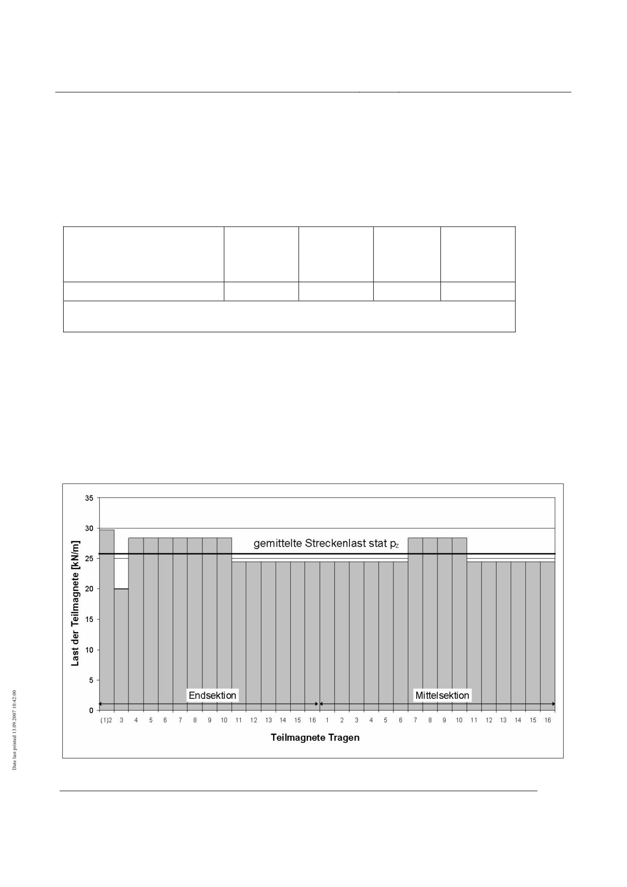
High-speed Maglev system
Maglev Technical Committee
Design principles
Vehicle
Vehicle self weight and payload
The characteristic values of the static actions resulting from the vehicle loading conditions are
given as the line load determined over the vehicle length in Table 80.
The static line loads given in Table 80 are to be used as a basis for determining the characteristic
values of actions of the vehicle.
Static line load per m vehicle
Permitted
Maximum
length (support magnet oc-
Vehicle self
Mean vehicle
vehicle
vehicle
cupied length) without snow
weight
weight
weight
weight
in [kN/m]
stat pz
19 1 (21)
26
29
31
1 applies to light goods vehicles,
for passenger vehicles a mean line load of 21 kN/m can be assumed.
Table 80: Characteristic static line loads of the vehicle (averaged)
The permitted weight G Sekt zul of a vehicle section can be calculated with the aid of the following
equation:
G Sekt zul = stat pz ⋅ LMS / g where g = 9.81 m/s² .
Any possible local increases in the line load ∆stat pz as a result of uneven distribution of the vehicle
weight over its length should be kept to a minimum.
A typical diagram for stat pz ± ∆ stat pz is shown in Fig. 86.
Fig. 86: Typical diagram for stat pz ± ∆ stat pz
Title
High-speed Maglev system design principles
Vehicle, Part IV, Levitation and guidance systems
Document
73388
Version
White Paper Issue date
15.02.2007
Page 29
no.:
High-speed Maglev system
Maglev Technical Committee
Design principles
Vehicle
Last der Teilmagnete
Load on partial magnets
Teilmagnete Tragen
Partial support magnets
gemittelte Streckenlast
Mean line load
Endsektion
End section
Mittelsektion
Centre section
Evidence of stat pz and ∆ stat pz for the defining loading conditions must be provided by weighting.
In certain cases the values of stat pz and ∆ stat pz for the vehicle with payload can be calculated on
the basis of the weighting in the unloaded state.
Quasi-static loads from driving dynamics
Driving over elements of the route such as bends, rises and depressions causes accelerations in the
y and z directions and during driving and braking of the vehicle quasi-static loads are generated in
the x, y and z directions and moments about the x, y and z axes which are affected by the location of
the centre of gravity of the vehicle sections in the z direction.
These actions must be taken into account on the guideway side as mass forces in the x, y and z di-
rections in accordance with /MSB AG-FW BEM/.
The centre of gravity of a section of the vehicle in the z direction must not exceed the following
values9:
• For vehicle self weight
600 mm above the sliding surface,
• For mean vehicle weight:
700 mm above the sliding surface,
• For permitted vehicle weight:
850 mm above the sliding surface,
• For maximum vehicle weight:
950 mm above the sliding surface.
Quasi-static loads from side wind (without lift)
As a consequence of the quasi-stationary effect of side wind (mean value over 5 s according to/MSB
AG-UMWELT/) on the vehicle, the vehicle transfers quasi-static loads to the guideway. The magni-
tude of the loads is determined by the speed of the side wind, the speed of the vehicle and the height
and geometry of the front of the vehicle.
These actions resulting from side wind on the vehicle must be taken into account on the guideway
side in accordance with /MSB AG-FW BEM/.
The actions given in the guideway design specifications and the associated distribution over the
length of the vehicle are respected if the maximum local line load owing to side wind in the y direc-
tion py, SW does not exceed the values given in Table 81.
9) The data is needed in this form for designing the guideway.
Title
High-speed Maglev system design principles
Vehicle, Part IV, Levitation and guidance systems
Document
73388
Version
White Paper Issue date
15.02.2007
Page 30
no.:
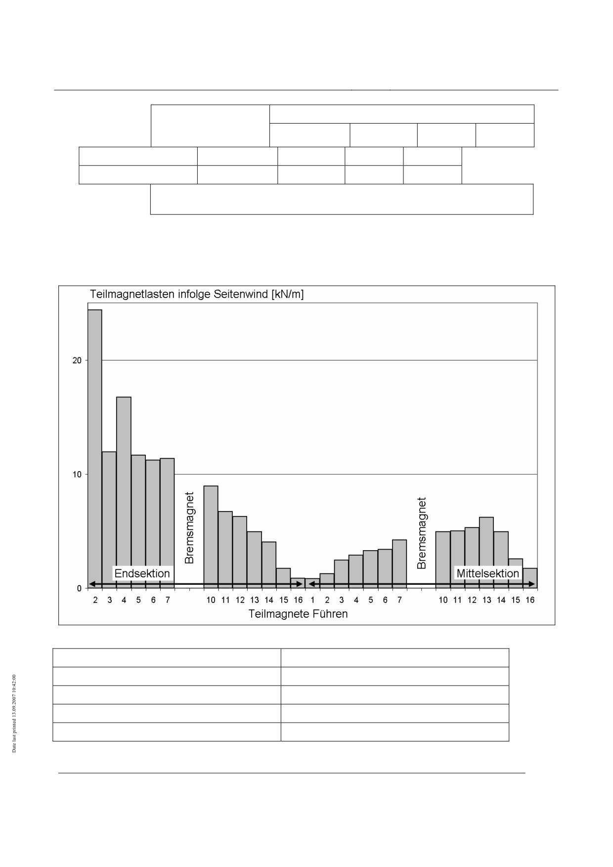
High-speed Maglev system
Maglev Technical Committee
Design principles
Vehicle
Maximum local line
Vehicle speed
load from side wind
200 km/h
300 km/h
400 km/h
500 km/h
in [kN/m]
py, SW
11.0
14.1
24.4
32.4
pz, SW
± 5.4
± 6.4
±6.9
± 7.4
The loads apply for a side wind speed of 37 m/z to wind load zone II at a height
of 20 m above ground.
Table 81: Actions resulting in side wind on the vehicle
The load certification can be done by calculation and simulation of flow behaviour with a verified
simulation model.
Fig. 87: Typical course of py, SW where vFzg= 400 km/h and SW = 37m/s
Teilmagnelasten infolge Seitenwind
Loads on partial magnets as a result of side wind
Teilmagnete Führen
Partial guidance magnets
Bremsmagnet
braking magnet
Endsektion
End section
Mittelsektion
Centre section
Title
High-speed Maglev system design principles
Vehicle, Part IV, Levitation and guidance systems
Document
73388
Version
White Paper Issue date
15.02.2007
Page 31
no.:
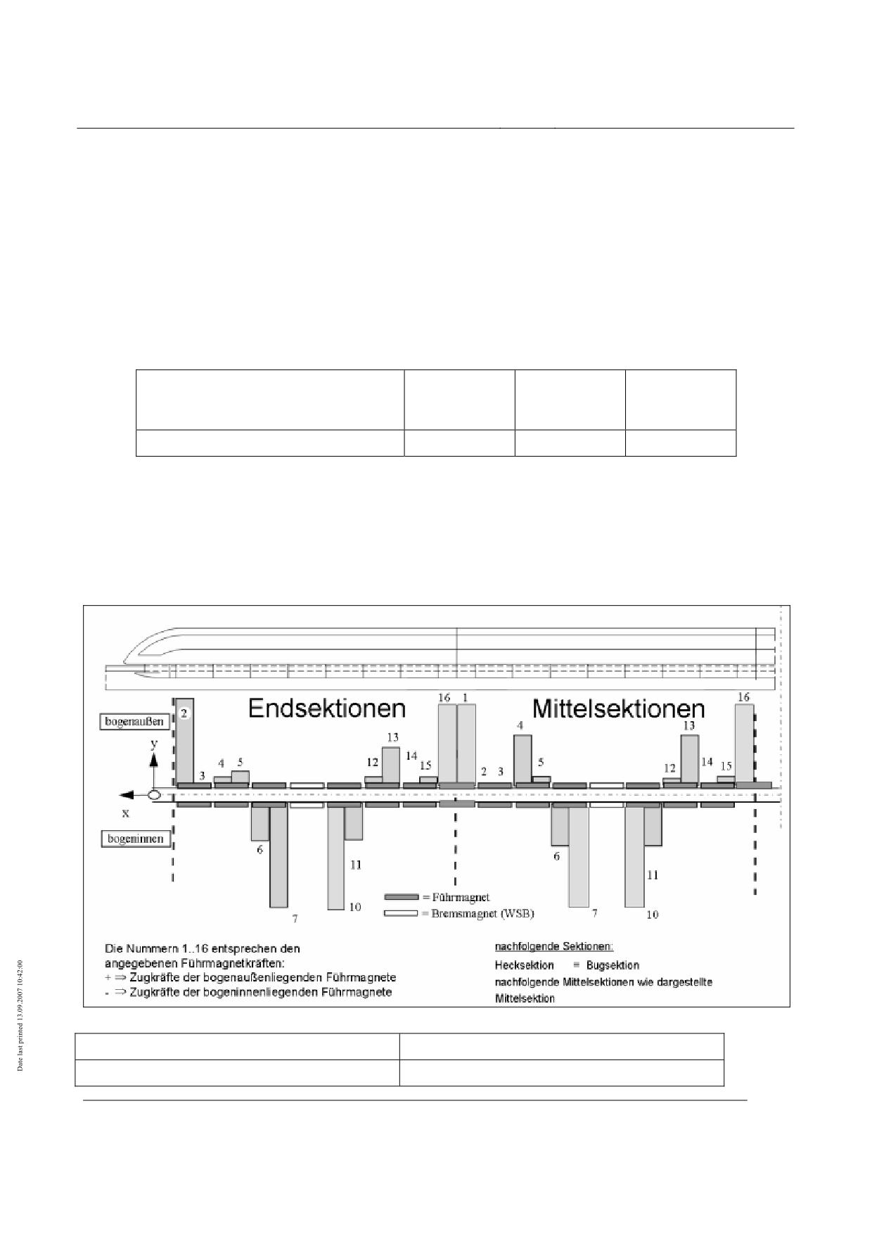
High-speed Maglev system
Maglev Technical Committee
Design principles
Vehicle
Quasi-static loads from restoring forces in small radius curves
In small radius curves, reset forces arise between the levitation chassis of the levitation and guid-
ance system and the carriage body (constraining forces), and these are transmitted to the guideway
as quasi-static loads in the
y direction. The maximum loads in each instance are transferred from the guidance magnets to the
ends and in the area of the centre of the section.
The actions given in the guideway design specifications and their distribution over the length of the
vehicle (see Fig. 88) are respected if the maximum local constraining force in the y direction py, ZWG
does not exceed the values given in Table 82.
Characteristic values of the maxi-
Radius of
Radius of
Radius of
mum constraining force in curves
curve RH =
curve RH =
curve RH =
in [kN/m]
350 m
1,000 m
2,000 m
py, ZWG
21
7
0
Table 82: Maximum local constraining force
The forces can be determined by calculation.
The calculation must be verified by measuring individual restoring forces in a representative vehicle
and curved section.
Fig. 88: Typical response for p
y, ZWG
Endsektionen
End sections
Mittelsektionen
Centre sections
Title
High-speed Maglev system design principles
Vehicle, Part IV, Levitation and guidance systems
Document
73388
Version
White Paper Issue date
15.02.2007
Page 32
no.:

High-speed Maglev system
Maglev Technical Committee
Design principles
Vehicle
Bogenaußen
Bow outside
Bogeninnen
Bow inside
Führmagnet
Guidance magnet
Bremsmagnet
Braking magnet
Die Nummern 1 ... 16 entsprechen den angegebenen
The numbers 1-16 correspond to the guidance mag-
Führmagnetkräften.
net forces shown.
Zugkräfte der bogenaußenliegenden Furhmagnete
Tensile forces of the guidance magnets outside the
bow
Zugkräfte der bogeninnenliegenden Furhmagnete
Tensile forces of the guidance magnets inside the
bow
nachfolgende Sektionen
Following sections
Hecksektion = Bugsektion
Tail section = bow section
nachfolgende Mittelsektionen wie dargestellte Mit-
Following centre sections as centre section shown
telsektion
Loads from driving and braking with the long stator
For the maximum overall actions of a vehicle section on the guideway a maximum force in the x
direction that is obtained from the product of the permitted vehicle weight with the maximum per-
mitted acceleration or braking deceleration of (ax = 1.5 m/s²) is to be used as a regularly repeating
action (see Table 83).
This also covers the propulsion/braking situations where the track rises and falls.
For the maximum overall actions of a vehicle section on the guideway a maximum force in the X
direction of 250 kN / section is to be used as accidental action (see Table 83).
Characteristic values of maximum forces as a result of
propulsion and using the propulsion system for braking
Regularly repeating action with permitted vehicle
Fx = 110 kN / section
weight (ax ≤ 1.5 m/s²)
Case 1: Fx = 185 kN / section (distribution ratio 0.73
/ 0.27 on the right and left sides of the vehicle)
Accidental action
e.g. if the propulsion function is faulty
Case 2: Fx = 250 kN / section (uniform distribution
ratio on the right and left sides of the vehicle)
Table 83: Driving and braking forces with the long stator
The following relationships between the local action in the z direction pz and the local action in the
x direction px must be taken into account:
px ± ∆ px = ( pz ± ∆ p ) ⋅ax / g
Maximum loads at the support magnet - stator pack interface
Title
High-speed Maglev system design principles
Vehicle, Part IV, Levitation and guidance systems
Document
73388
Version
White Paper Issue date
15.02.2007
Page 33
no.:

High-speed Maglev system
Maglev Technical Committee
Design principles
Vehicle
Induced loads
At the interface between the support magnet (TM) and the stator level there is a magnetic transfer
of quasi-static and dynamic tensile forces in the z direction and there is a magnetic transfer of
thrust forces in the x direction via the propulsion function of the long stator.
The following values must be taken into consideration as characteristic values for the maximum
loads per metre of half magnet length:
Direction of
Load per m
Design situations
action
of support magnet
Max. static tensile force from
z direction
16 kN/m
- permitted total weight
Max. dynamic tensile force from
- permitted total weight
z direction
20 kN/m
- ay = 1.5m/s², az = 1.2m/s²,
Side wind 10m/s at 400 km/h
Max. local tensile force in sectional magnet operation and
- permitted total weight
z direction
45 kN/m
- ay = 1.5m/s², az = 1.2m/s²,
Side wind 37m/s at 400 km/h, Fz_dyn_max
Maximum thrust of the propulsion system without technical
failures or faults(max ax = 1.5 m/s²) from
x direction
2.25 kN/m
- permitted overall weight (inc. uneven distribution)
Maximum thrust in the event of failure of the propulsion system
Case 1: 5.5 kN/m
x direction
(see Table 83)
Case 2: 5.0 kN/m
Max. local thrust in the event of failure of a levitation control
x direction
4 kN/m
device
The maximum levitation force of the support magnet must be limited to 45 kN/m.
Table 84: Maximum support magnet load
For local load distribution see Fig. 89 and Fig. 90.
Dynamic excitation
The local distribution of the forces of the support magnets in the x direction is subject to periodicity
of phase spacing that acts on the guideway as a force wave and moves along the guideway at the
vehicle speed v. In the guideway the force wave coming from the vehicle acts as a locally pulsating
steady force at a frequency fe that is dependent on the wavelength of the force λe, its harmonics and
the vehicle speed.
fe = v / λe
The following actions must be taken into account with respect to dynamic excitation of the guide-
way:
Continuously acting variable forces as the vehicle travels over the guideway:
Title
High-speed Maglev system design principles
Vehicle, Part IV, Levitation and guidance systems
Document
73388
Version
White Paper Issue date
15.02.2007
Page 34
no.:
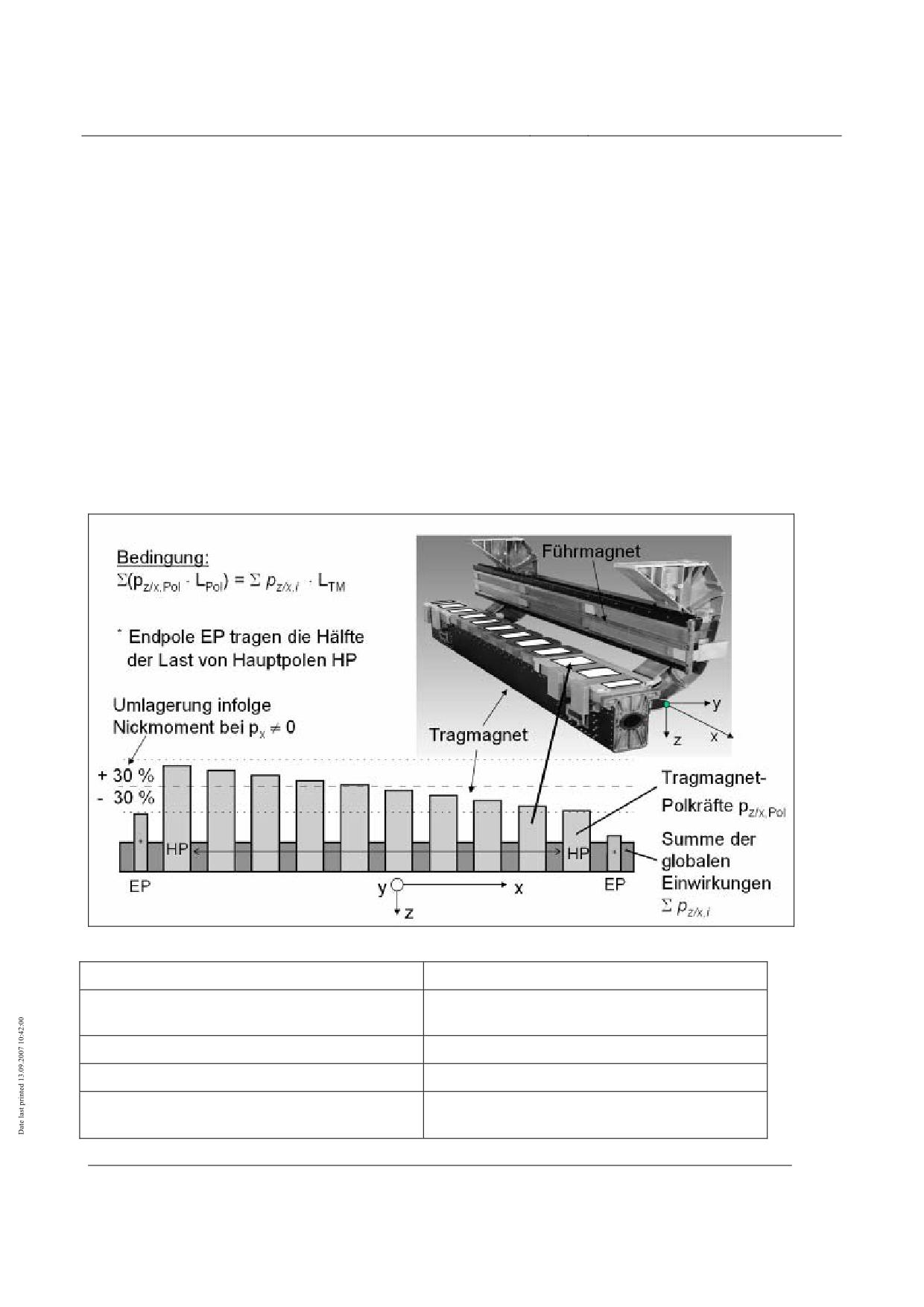
High-speed Maglev system
Maglev Technical Committee
Design principles
Vehicle
• Geometry of the support magnet poles
magnetic effect of the pole geometry at the surface of the pole. e.g. from slots for linear genera-
tors
• Geometry of the arrangement of the support magnet poles in the response of a support magnet,
local movement of the force along the support magnet
• Geometry of the arrangement of the support magnet poles at the ends of a support magnet,
local movement of the force in the area between two support magnets resulting from a different
geometry at the end of the magnet poles from that in the centre
• Force caused by pitching of the support magnet because of the propulsion forces transmitted,
torsion of the individual support magnets about the y axis, "misalignment" (Fig. 89)
Variable forces acting occasionally as the vehicle travels over the guideway:
• Forces in the region of two support magnets after the failure of one magnet control device (Fig.
90)
Fig. 89: Typical load arrangement for support magnet without technical faults and breakdowns (Example)
Bedingung
Condition
Endpolen EP tragen die Hälfte der last von Haupt-
End poles bear half of the loads of main poles HP
polen HP
Führmagnet
Guidance magnet
Tragmagnet
Support magnet
Umlagerung infolge Nickmoment bei px ≠ 0
Superimposition owing to pitching moment when
px ≠
Title
High-speed Maglev system design principles
Vehicle, Part IV, Levitation and guidance systems
Document
73388
Version
White Paper Issue date
15.02.2007
Page 35
no.:
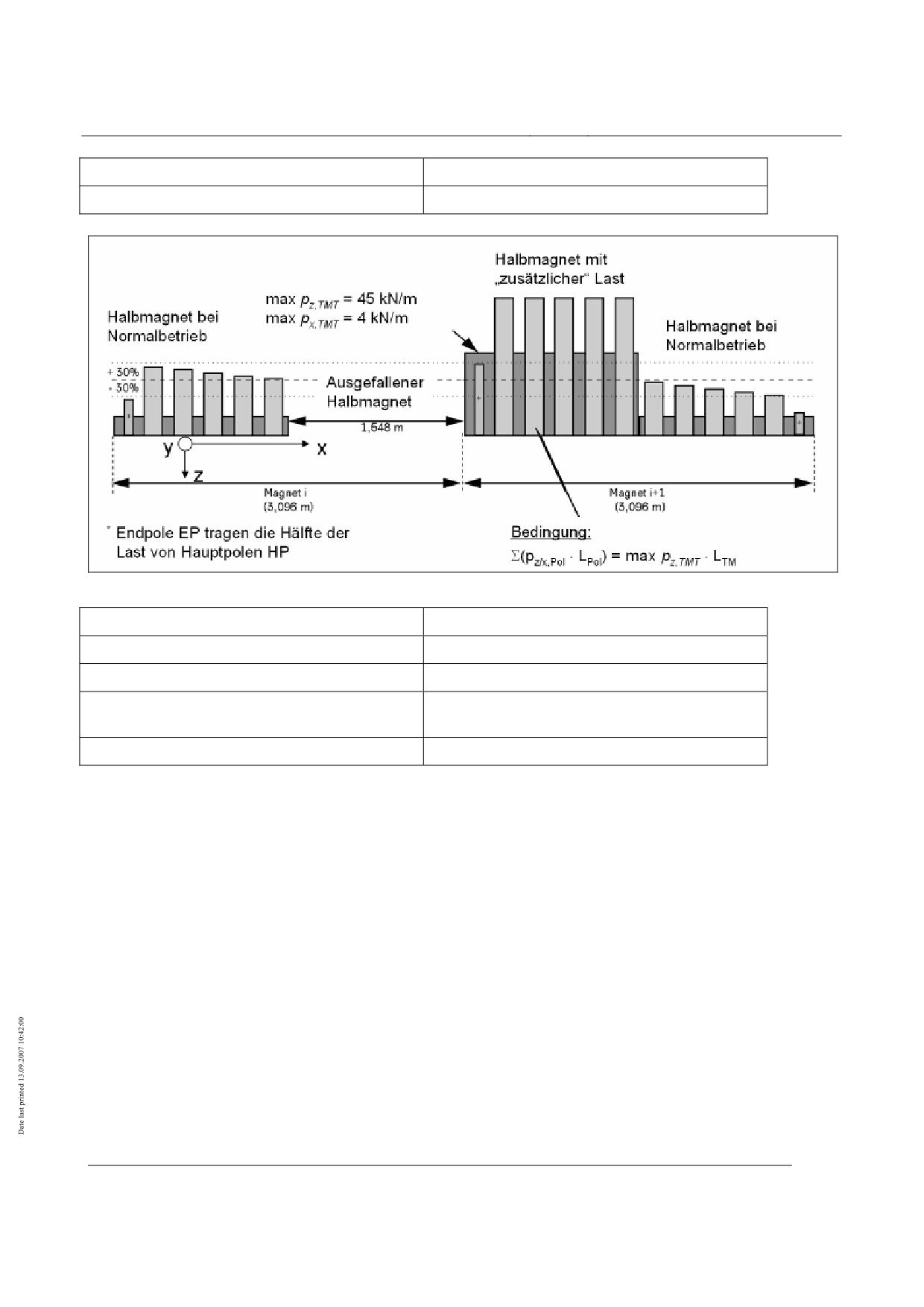
High-speed Maglev system
Maglev Technical Committee
Design principles
Vehicle
Tragmagnet-Polkräfte
Support magnet pole forces
Summe der globalen Einwirkungen
Sum of total actions
Fig. 90: Typical load arrangement for support magnet in the event of a support magnet circuit failure (Example)
Halbmagnet bei Normalbetrieb
Half magnet in normal operation
Halbmagnet mit "zusätzlicher" last
Half magnet with "additional" load
Ausgefallener Halbmagnet
Failed half magnet
Endpolen EP tragen die Hälfte der last von Haupt-
End poles bear half of the loads of main poles HP
polen HP
Bedingung
Condition
Title
High-speed Maglev system design principles
Vehicle, Part IV, Levitation and guidance systems
Document
73388
Version
White Paper Issue date
15.02.2007
Page 36
no.:
High-speed Maglev system
Maglev Technical Committee
Design principles
Vehicle
Maximum loads at the support magnet - lateral guidance rail
interface
Induced loads
The following loads are transmitted at the interface between the guidance magnet (FM) and the
lateral guidance rail (SFS):
• Magnetic quasi-static and dynamic tensile forces in the y direction during operation without
technical failures or faults,
• Mechanical quasi-static and dynamic compressive forces in the y direction during operation
with technical failures or faults,
• Frictional forces in the x direction as a result of mechanical compressive forces during special
operation.
The following values must be taken into consideration as characteristic values for the maximum
loads per metre of partial magnet length.
Direction of
Load per m
Design situations
action
of guidance magnet
Max. tensile force and
- permitted total weight
y direction
25 kN/m
- ay = 1.5 m/s², ax = 1.1 m/s² (WSV),
Side wind 10 m/s at 400 km/h, RH = 1000 m
Max. tensile force in sectional magnet operation and
- permitted total weight
10
y direction
32 kN/m
- ay = 1.5 m/s², ax = 1.1 m/s²(WSV), RH = 1000 m
- Side wind 37 m/s at 400 km/h, Fz_dyn_mittel
- Max quasi-stationary compressive force in the event
of failure of the magnetic guidance function in an
y direction
25 kN/m
individual levitation undercarriage
- Frictional force from quasi-stationary compressive
x direction
7.5 kN/m
force
The centre of gravity of the load introduced in the z direction varies with the type of guidance magnet and in
the event of guidance control equipment failure.
The maximum guidance force of a guidance magnet must be limited to 16 kN/m for a single pole
and 32 kN/m for a double pole.
Table 85: Maximum line loads
For local load distribution and the definition of single pole / double pole see Fig. 91.
10) If the maximum guidance force of 32 kN/m is exceeded this leads to mechanical lateral guidan-
ce(see chapter 0).
Title
High-speed Maglev system design principles
Vehicle, Part IV, Levitation and guidance systems
Document
73388
Version
White Paper Issue date
15.02.2007
Page 37
no.:
High-speed Maglev system
Maglev Technical Committee
Design principles
Vehicle
The following values must be taken into consideration as characteristic values for the maximum
impact force:
Direction of
Load per
Design situations
action
guidance magnet
- Max dynamic impact force in the event of failure of
the magnetic guidance function in an individual levita-
y direction
115 kN
tion undercarriage and gusts of side wind.
- Frictional force from dynamic impact force
x direction
34.5 kN
The centre of gravity of the load introduced in the z direction varies with the type of guidance magnet and in
the event of guidance control equipment failure.
Table 86: Maximum impact force
Title
High-speed Maglev system design principles
Vehicle, Part IV, Levitation and guidance systems
Document
73388
Version
White Paper Issue date
15.02.2007
Page 38
no.:
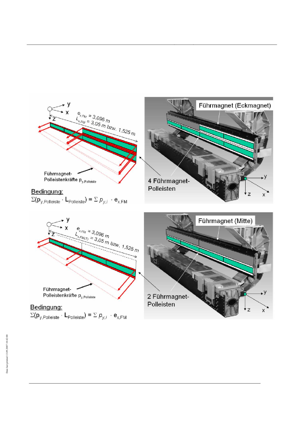
High-speed Maglev system
Maglev Technical Committee
Design principles
Vehicle
Dynamic excitation
In the case of the guideway, possible excitation from the arrangement of the guidance magnets must
be taken into account.
Double pole:
right-hand guidance magnet (corner
magnet)
Single pole:
left-hand guidance magnet (corner
magnet)
Guidance magnet (centre)
Title
High-speed Maglev system design principles
Vehicle, Part IV, Levitation and guidance systems
Document
73388
Version
White Paper Issue date
15.02.2007
Page 39
no.:
High-speed Maglev system
Maglev Technical Committee
Design principles
Vehicle
Fig. 91: Typical load arrangements of guidance magnets (example)
Führmagnet-Polleistenkräfte
Guidance magnet pole strip forces
Bedingung
Condition
Führmagnet (Eckmagnet)
Guidance magnet (corner magnet)
Führmagnet-Polleisten
Guidance magnet pole strips
Führmagnet (Mitte)
Guidance magnet (centre)
Maximum loads at the support skid - sliding surface interface
Induced loads
In the event of levitation system failures the sliding surface (GL) at the interface between the sup-
port skid and the sliding surface is subjected to the following loads:
In the z direction (compressive load):
• proportional quasi-static and dynamic load of a sliding levitation undercarriage
• transient impact load from the uncontrolled setting down of a levitation undercarriage
in the x direction:
• force resulting from the load in the z direction and the coefficient of friction.
The following values must be taken into consideration as characteristic values for the maximum
loads imposed by an individual support skid.
Characteristic values of the maximum
Direction of
Load per support
skid forces in [kN]
action
skid
Static vehicle at 16° transverse inclination
y
14
z
50
Quasi-static and dynamic com-
15 or 25 in the event
pressive force
x
Levitating
of stiction
vehicle
z
100
Impact force limit
x
30
z
-50
Frozen-on support skid
x
25
Table 87: Maximum support skid forces
For local load distribution see Fig. 92.
Title
High-speed Maglev system design principles
Vehicle, Part IV, Levitation and guidance systems
Document
73388
Version
White Paper Issue date
15.02.2007
Page 40
no.:
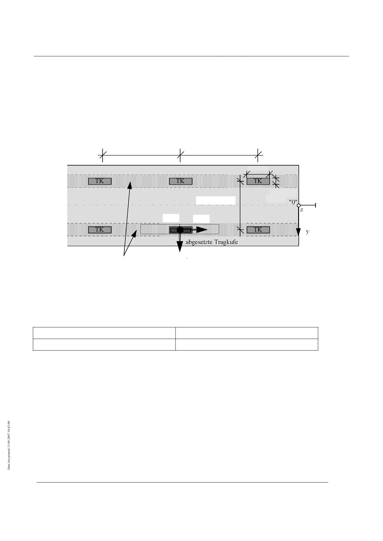
High-speed Maglev system
Maglev Technical Committee
Design principles
Vehicle
Dynamic excitation
Excitation as a result of local actions of the support skid can be ignored as far as the guideway is
concerned.
ex,TK = 3096 mm
ex,TK = 3096 mm
740 mm
110 mm
ey,TK = 2220 mm
Fz,TK
Fx,TK
TMTi
TMT
i+1
Fy,TK
Gleitebene
Fig. 92: Load arrangements of support skid (example
abgesetzte Tragkufe
Set down support skid
Gleitebene
Slideway
Title
High-speed Maglev system design principles
Vehicle, Part IV, Levitation and guidance systems
Document
73388
Version
White Paper Issue date
15.02.2007
Page 41
no.:
High-speed Maglev System
Maglev Technical Commit-
tee
Design principles
Vehicle
High-speed Maglev System
Design principles
Vehicle
Part V
Brake system
All rights reserved
Title
High-speed Maglev system Design principles
Vehicle, Part V, Braking system
Document
73389
Version
White Pa-
Issue date
15.02.2007
Page 1
no.:
per
High-speed Maglev System
Maglev Technical Commit-
tee
Design principles
Vehicle
Distribution
The Vehicle Committee has released this document for publication.
Title
High-speed Maglev system Design principles
Vehicle, Part V, Braking system
Document
73389
Version
White Pa-
Issue date
15.02.2007
Page 2
no.:
per
High-speed Maglev System
Maglev Technical Commit-
tee
Design principles
Vehicle
Revisions
Date of release: 15.02.2007; White Paper, Vehicle Committee.
Title
High-speed Maglev system Design principles
Vehicle, Part V, Braking system
Document
73389
Version
White Pa-
Issue date
15.02.2007
Page 3
no.:
per
High-speed Maglev System
Maglev Technical Commit-
tee
Design principles
Vehicle
Contents
Distribution
2
Change history
3
List of contents
4
General
5
Distribution
2
Revisions
3
Contents
4
General
6
Purpose and applications
6
High-speed Maglev system design principles
6
Abbreviations and Definitions
7
Legislation, regulations, standards and directives
8
Identification and mandatory nature of requirements
8
Definitions (vehicle-specific)
9
General requirements of the braking system
12
Subsystems and equipment
12
Operation
15
Design and ratings
17
Safety requirements
18
Requirements for the on-board energy supply
19
Requirements for the execution of a set-down command
19
Systematic faults in the braking system
19
Taking friction pairing into account
19
Braking magnet / lateral guidance rail,
19
Support skids / sliding surface
20
Requirements for the braking equipment
21
Generation of braking force
21
Properties and functions
21
Effect of failure
21
Failure reporting
21
Title
High-speed Maglev system Design principles
Vehicle, Part V, Braking system
Document
73389
Version
White Pa-
Issue date
15.02.2007
Page 4
no.:
per
High-speed Maglev System
Maglev Technical Commit-
tee
Design principles
Vehicle
Certificates
21
Control and monitoring of the braking effect
23
Properties and functions
23
Behaviour in the event of failure
23
Certificates
23
Actions of the braking equipment on the guideway
24
General
24
Types and combinations of actions
24
Forces and load arrangements
25
Overall actions on the guideway
25
Braking magnet - lateral guidance rail interface
25
Support skid / sliding surface interface
26
List of figures
Fig. 12: Side view and cross-section of a vehicle, identifying the braking equipment (schematic). 10
Fig. 13: Magnet module (example)
10
Fig. 14: View of a braking magnet (example), definition of the essential components
10
Fig. 15: Support skid (example)
11
Fig. 16: Subsystems and equipment involved in safe braking (example)
13
Fig. 17: Braking characteristic for the safe brake for a vehicle section (Figure 10 taken from chapter
8.5 of /MSB AG-GESAMTSYS/)
17
Fig. 18: Project structure for safety-relevant systems (Part I / project-specific example)
27
Fig. 19: Project structure for safety-relevant systems (Part II / project-specific example)
28
List of tables
TOC
Title
High-speed Maglev system Design principles
Vehicle, Part V, Braking system
Document
73389
Version
White Pa-
Issue date
15.02.2007
Page 5
no.:
per
High-speed Maglev System
Maglev Technical Commit-
tee
Design principles
Vehicle
General
Purpose and applications
• This "High-speed magnetic levitation railway vehicle design principles, part V - Brake sys-
tems" sets out the requirements for the safe braking systems installed in the vehicle.
• It applies to a Maglev system in accordance with the General Maglev System Act /AMbG/.
• The "long stator" control braking system is not covered in this document (see /MSB AG-
GESAMTSYS/).
• Part V is to be used for the specification, execution and certification of the braking systems
of MAGLEV vehicles.
• Any deviations from the requirements and definitions given in this document require equal
safety in accordance with /MbBO/ of the certificate.
• Part V of the "MAGLEV vehicle performance specification" comprises:
Definition of the braking equipment;
Requirements for the braking equipment;
The actions of the braking equipment on the guideway;
Description of the interfaces with other systems (on-board operational control system (BLT), on-
board energy supply).
• The requirements for a secure vehicle braking system are summarized. The document
does not include a description of the braking control and monitoring by the BLT. This is
given in /MSB AG-BLT/.
High-speed Maglev system design principles
• This document is part of the documentation for high-speed magnetic levitation railways
consisting of a number of design principles. Figure 1 /MSB AG-GESAMTSYS/ shows the
documentation tree.
• The overall design principles for the complete system and its appendices apply uniformly to
all the documentation.
•
High-speed Maglev system design principles, complete system, Document no.: 50630,
/MSB AG-GESAMTSYS/, with appendices:
•
Annex 1: Abbreviations and definitions, Document no.: 67536, /MSB AG-ABK&DEF/
•
Annex 2: Legislation, regulations, standards and directives, Document no.: 67539, /MSB
AG-NORM&RILI/
•
Annex 3: Environmental constraints, Document no.: 67285, /MSB AG-UMWELT/
•
Annex 4: Operating rules (operation and maintenance), Document no.: 69061, /MSB
AG-BTR/
Title
High-speed Maglev system Design principles
Vehicle, Part V, Braking system
Document
73389
Version
White Pa-
Issue date
15.02.2007
Page 6
no.:
per