Design Principles High-speed Maglev System. Information (MSB, 2007) - page 5
High-speed Maglev System
Maglev Technical Commit-
tee
Design Principles
Vehicle
Amendment summary:
Date of release: 15.02.2007; White Paper, Vehicle Technical Committee.
Title
High-speed Maglev System Design Principles
Vehicle Part I, General Requirements
Doc.no.:
67698
Version
White paper
Issue date
15.02.2007
Page 3
High-speed Maglev System
Maglev Technical Commit-
tee
Design Principles
Vehicle
Table of Contents
Distribution
2
Amendment summary:
3
Table of Contents
4
General
6
Purpose and scope
6
High-speed Maglev System Implementation Bases
6
Abbreviations and definitions
8
Acts, Orders, Standards and Directives
8
Identification and binding force of requirements
9
References
9
Definitions (vehicle-specific)
10
General requirements
20
Function
20
Design of mechanical components
20
Fundamental design principles
20
Collision behaviour
20
Safety requirements
21
Safety-related functions
21
Fire safety
21
Body
24
Support/guidance system, braking equipment
25
Annex Weighing the Maglev Vehicle
26
Preparation
26
Terms of reference and boundary conditions
26
Measurement below support skids
28
Measurement beneath the backs of the support magnets
29
Supplementary measured quantities
30
Evaluation
30
Documentation
32
Annex List of requirements for acceptance (example)
33
Title
High-speed Maglev System Design Principles
Vehicle Part I, General Requirements
Doc.no.:
67698
Version
White paper
Issue date
15.02.2007
Page 4
High-speed Maglev System
Maglev Technical Commit-
tee
Design Principles
Vehicle
Table of Figures
Fig. 10: Side view and front view of a vehicle (schematic diagram)
11
Fig. 11: Vehicle cross-section (schematic diagram)
12
Fig. 12: Main subdivision of vehicle
13
Fig. 13: Subdivision of body
14
Fig. 14: Subdivision of support/guidance system
15
Fig. 15: Designations of essential body structure assemblies (examples)
16
Fig. 16: Designations of fairing elements of body and support/guidance system
(schematic diagram)
17
Fig. 17: Designations of essential assemblies of the support/guidance system (schematic
diagram side view)
18
Fig. 18: Designations of essential assemblies and dimensions of the support/guidance
system (schematic diagram cross-section)
18
Fig. 19: Designations of essential assemblies of the underbody structure (schematic
diagram)
19
Fig. 20: Schematic diagram for the method of measurement beneath the support skid..28
Fig. 21: Schematic diagram of the method of measurement beneath the backs of the
support magnets
29
Fig. 22: Example of measurement results for a vehicle with three sections in the form of a
table and chart (hypothetical measured values)
31
Fig. 23: Example of a schematic diagram for the coupling supporting forces and their
effective direction on a vehicle with three sections
31
Fig. 24: Example of a schematic diagram showing the supplementary measured
quantities for pneumatic spring pressure, levelling position, coupling supporting force
and position of the extra weights on a vehicle with three sections
32
Title
High-speed Maglev System Design Principles
Vehicle Part I, General Requirements
Doc.no.:
67698
Version
White paper
Issue date
15.02.2007
Page 5
High-speed Maglev System
Maglev Technical Commit-
tee
Design Principles
Vehicle
General
Purpose and scope
The present Design Principles Vehicle Part I “General Requirements” lay down the gene-
ral requirements for the vehicle and the certification procedure
The present Design Principles apply to a high-speed maglev system pursuant to the Gene-
ral Maglev Act [Allgemeines Magnetschwebebahngesetz /AMbG/].
The present document shall be applied to the specification, execution and certification of
maglev vehicles.
Project-specific requirements shall be agreed between the approval authority, high-speed
maglev system operator (operator) and vehicle supplier. These shall be documented in the
target requirements (supply and performance specification) based on the maglev opera-
tor’s specification.
The term “vehicle” in the Design Principles Vehicle (Parts I - V) shall exclusively be
taken to mean a levitated vehicle of a high-speed maglev system.
Deviations from the requirements and stipulations in this document require proof of iden-
tical safety.
This Part I of the Design Principles Vehicle comprises:
• Definitions of the vehicle structure and assemblies;
• General requirements for vehicles;
• Requirements for acceptance.
High-speed Maglev System Implementa-
tion Bases
This document forms part of a set of documentation for high-speed maglev systems
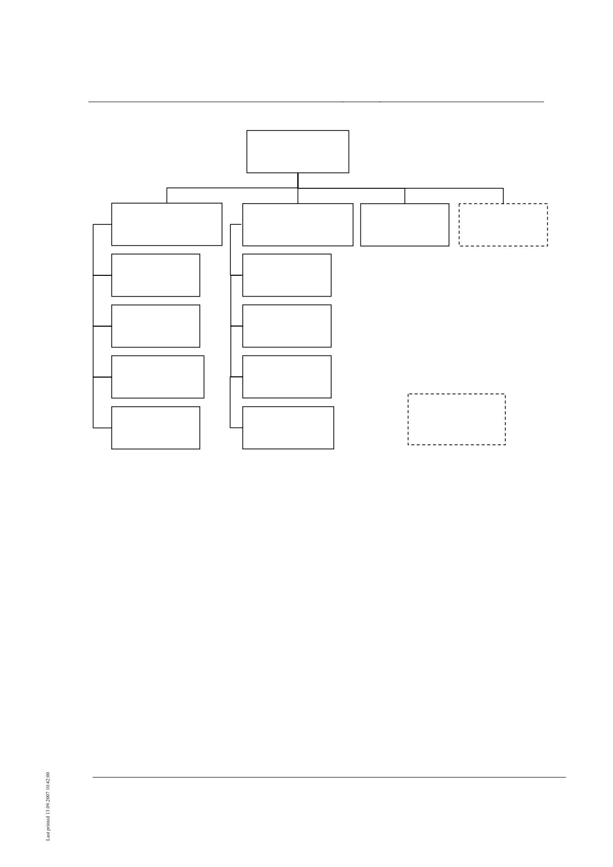
comprising several Implementation Bases. The documentation tree is shown in Figure 1
/MSB AG-GESAMTSYS/.
The parent Design Principles Complete System and the Annexes thereof apply uniformly
to the full set of documentation:
•
High-speed Maglev System Design Principles Complete System, doc. no.: 50630,
/MSB AG-GESAMTSYS/, with Annexes:
•
Annex 1: Abbreviations and definitions, doc. no.: 67536, /MSB AG-
ABK&DEF/
•
Annex 2: Acts, Orders, Standards and Directives, doc. no.: 67539, /MSB AG-
NORM&RILI/
Title
High-speed Maglev System Design Principles
Vehicle Part I, General Requirements
Doc.no.:
67698
Version
White paper
Issue date
15.02.2007
Page 6
High-speed Maglev System
Maglev Technical Commit-
tee
Design Principles
Vehicle
•
Annex 3: Environmental Conditions, doc. no.: 67285, /MSB AG-
ENVIRONMENT/
•
Annex 4: Operating Rules (Driving and Maintenance), doc. no.: 69061, /MSB
AG-BTR/
•
Annex 5: Sound, doc. no.: 72963, /MSB AG-SCHALL/
The documentation relating to the vehicle comprises the following:
•
High-speed Maglev System Design Principles Vehicle, Part I: General Require-
ments, doc. no.: 67698, /MSB AG-FZ GEN/
•
High-speed Maglev System Design Principles Vehicle, Part II: Dimensioning,
doc. no.: 67694, /MSB AG-FZ BEM/
•
High-speed Maglev System Design Principles Vehicle, Part III: Kinematic gauge,
doc. no.: 67650, /MSB AG-FZ KIN/
•
High-speed Maglev System Design Principles Vehicle, Part IV: Support/guidance
Engineering, doc. no.: 73388, /MSB AG-FZ TRAFÜ/
•
High-speed Maglev System Design Principles Vehicle, Part V: Brake Engineering,
doc. no.: 73389, /MSB AG-FZ BREMS/
Overriding definitions of the interfaces between the individual subsystems are given in
High-speed Maglev System Complete System /MSB AG-GESAMTSYS /. The High-
speed Maglev System Design Principles Complete System shall therefore always be used
in conjunction with the other Implementation Bases.
The contents of Parts I to V of the High-speed Maglev System Implementation Bases Ve-
hicle are summarised under the bullet points below:
Part I
General Requirements
• Definitions of the vehicle structure and assemblies;
• General requirements for vehicles;
• Requirements for acceptance.
Part II Design
• Stipulation of operating conditions, influences and combinations of influences;
• Certification of static strength and fatigue strength, stability and rigidity.
Part III Kinematic gauge
Title
High-speed Maglev System Design Principles
Vehicle Part I, General Requirements
Doc.no.:
67698
Version
White paper
Issue date
15.02.2007
Page 7
High-speed Maglev System
Maglev Technical Commit-
tee
Design Principles
Vehicle
• Definition of the kinematic functions;
• Definition of the relevant geometric data and failure states;
• Terms of reference for proof of gauge.
Part IV Support/guidance Engineering
• Definition of the support/guidance system;
• Requirements for support/guidance system functions;
• Influences of the support/guidance system on the guideway.
Part V
Brake Engineering
• Definition of braking equipment;
• Requirements for functions of the braking equipment;
• Influences of braking equipment on the guideway.
Abbreviations and definitions
The abbreviations and definitions given in /MSB AG-ABK&DEF/ apply.
Acts, Orders, Standards and Directives
The normative documents listed in /MSB AG-NORM&RILI/ contain stipulations which
become part of the High-speed Maglev System Implementation Bases by virtue of refe-
rence in the High-speed Maglev System Implementation Bases. When normative docu-
ments in /MSB AG-NORM&RILI/ are dated, later amendments or revisions of these
publications do not apply. When references are undated, the most recent issue of the nor-
mative document referred to is applicable.
The issue date of the Standards and Directives to be taken into account in a maglev pro-
ject shall be fixed with binding force for that specific project.
The checklist in Annex 0 of this document mentions Standards, compliance with which -
inasmuch as applicable to the high-speed maglev system - can be checked in principle on
acceptance of the vehicle pursuant to Section 6 /MbBO/.
The attached checklist serves as an example. It shall be agreed on a project-specific basis
between the approval authority, the high-speed maglev system operator and the vehicle
supplier, together with the Standards and test and certification procedures to be used.
If Standards for the high-speed maglev system are not recognised as uniquely applicable,
further maglev-specific Implementation Bases may be compiled by the Maglev Technical
Committee Vehicle.
There are, in addition, other Standards, e.g. material standards, fabrication standards,
maintenance standards, compliance with which is not explicitly checked as part of ac-
Title
High-speed Maglev System Design Principles
Vehicle Part I, General Requirements
Doc.no.:
67698
Version
White paper
Issue date
15.02.2007
Page 8
High-speed Maglev System
Maglev Technical Commit-
tee
Design Principles
Vehicle
ceptance pursuant to Section 6 /MbBO/, but compliance with which is the responsibil-
ity of the manufacturer or operator.
Identification and binding force of re-
quirements
In compiling the present document, the regulations conforming to /DIN 820/ were essen-
tially applied.
In the following chapters and annexes of this document
• requirements are denoted by regular font
• explanatory notes, guideline values and examples are denoted by italics.
If references are made in this document to project-specific regulations in an individual
case, this means that agreement shall be reached between manufacturer and operator (e.g.
in specifications or a contractual arrangement) in consultation with the approval authori-
ty.
References
The references listed below represent a summary of the reference sources referred to in
this document. A complete list of all the reference documentation referred to in the MSB
Implementation Bases will be found in /MSB AG-NORM&RILI/.
Document
Description
/BrandReg/
Regulation for the fire safety rating of railbound vehicles as part of
acceptance in accordance with Section 32 EBO;
Principles of fire safety requirements with reference to EN 45545;
Agreement between Federal Railways Office, Deutsche Bahn AG,
German Railway Industry Association, 01.06.2006
Title
High-speed Maglev System Design Principles
Vehicle Part I, General Requirements
Doc.no.:
67698
Version
White paper
Issue date
15.02.2007
Page 9
High-speed Maglev System
Maglev Technical Commit-
tee
Design Principles
Vehicle
Definitions (vehicle-specific)
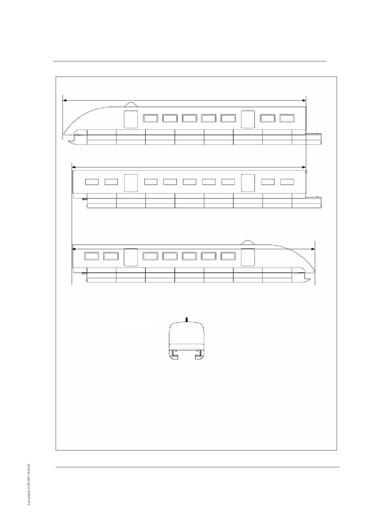
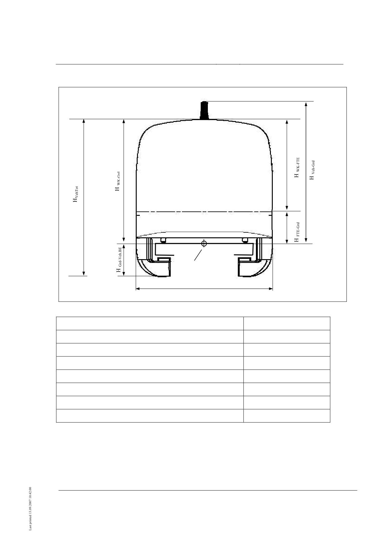
Fig. 49 and Fig. 50 show the side and front view and cross-section of a typical ve-
hicle and explain the characteristic dimensions.
The vehicles shall be formed from vehicle sections which are autarkic in respect
of support and guidance function, braking equipment, on-board energy supply
and bodywork.
The connection of vehicle sections may be effected by section-connecting lift
magnets and by a section coupling (see Fig. 49, Fig. 54, Fig. 56).
There are end sections and mid sections. An end section differs from a mid secti-
on in having a nose additional to the cell structure (Fig. 54).
The underbody structure of the support/guidance system below the nose may be
a nose fairing rigidly mounted to the frame (see Fig. 55).
The equipment of the operational control system, radio facilities and detection
devices required for the functioning of the operational controls and the drive can
be integrated in the end sections.
A vehicle may have 2 end sections and up to 8 mid sections1).
The system length of a vehicle section must correspond to the geometric length
of an LMS mid section.
LMS is equivalent to 8 times the lift magnet system length (Lsys,TM) and 96 times
the pole pitch (ex,pole pitch):
LMS = 8 · Lsys,TM
= 96 · ex,pole pitch
= 8 · 3 096 mm = 96 · 258 mm
= 24 768 mm
LMS is the geometric length of a mid section over centre of section coupling or
centre of section-connecting lift magnets.
The geometric length of the end section LES may deviate from the system length
of the mid section LMS - depending on the design and dimensions of the nose.
The geometric vehicle length LVeh of a vehicle with 2 end sections and n mid sec-
tions is:
LVeh = 2 · LES + n · LMS .
1) Vehicles with only one end section may be used for special applications. Correspon-
ding project-specific adjustments are required.
Vehicles with up to 20 sections may be configured for special applications; here separate
certification is required.
Title
High-speed Maglev System Design Principles
Vehicle Part I, General Requirements
Doc.no.:
67698
Version
White paper
Issue date
15.02.2007
Page 10
High-speed Maglev System
Maglev Technical Commit-
tee
Design Principles
Vehicle
End section length LES
End section side view (E1)
Mid section length LMS
Mid section side view (M)
End section length LES
End section side view (E2)
Front view
•
Fig. 49: Side view and front view of a vehicle (schematic diagram)
Title
High-speed Maglev System Design Principles
Vehicle Part I, General Requirements
Doc.no.:
67698
Version
White paper
Issue date
15.02.2007
Page 11
High-speed Maglev System
Maglev Technical Commit-
tee
Design Principles
Vehicle
grade line
BWK-A
•
Fig. 50: Vehicle cross-section (schematic diagram)
Designation
Abbreviation
External body width
BWK-A
Height body over grade line (without antenna)
HWK-Grd
Height floor top edge over grade line
HFTE-Grd
Height vehicle (incl. antenna) over grade line
HVeh-Grd
Height outside body over floor top edge
HWK-FTE
Height grade line over vehicle bottom edge
HGrd-Veh.BE
Total vehicle height (without antenna)
HVeh.tot
Title
High-speed Maglev System Design Principles
Vehicle Part I, General Requirements
Doc.no.:
67698
Version
White paper
Issue date
15.02.2007
Page 12
High-speed Maglev System
Maglev Technical Commit-
tee
Design Principles
Vehicle
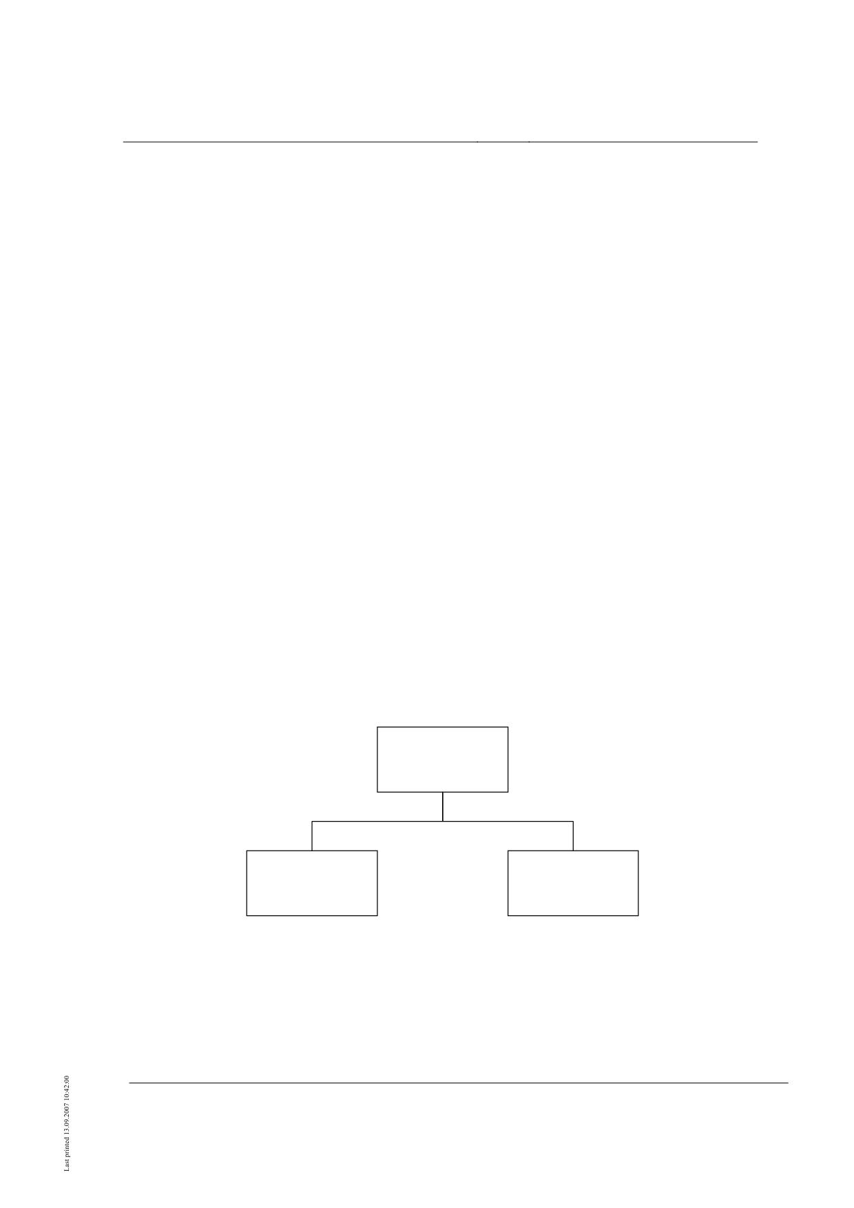
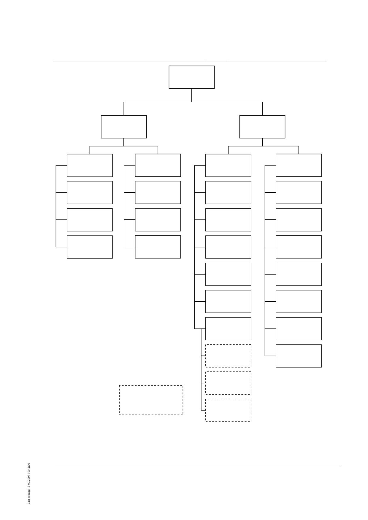
The vehicle is divided up as shown in the diagrams (Fig. 51 to Fig. 53).
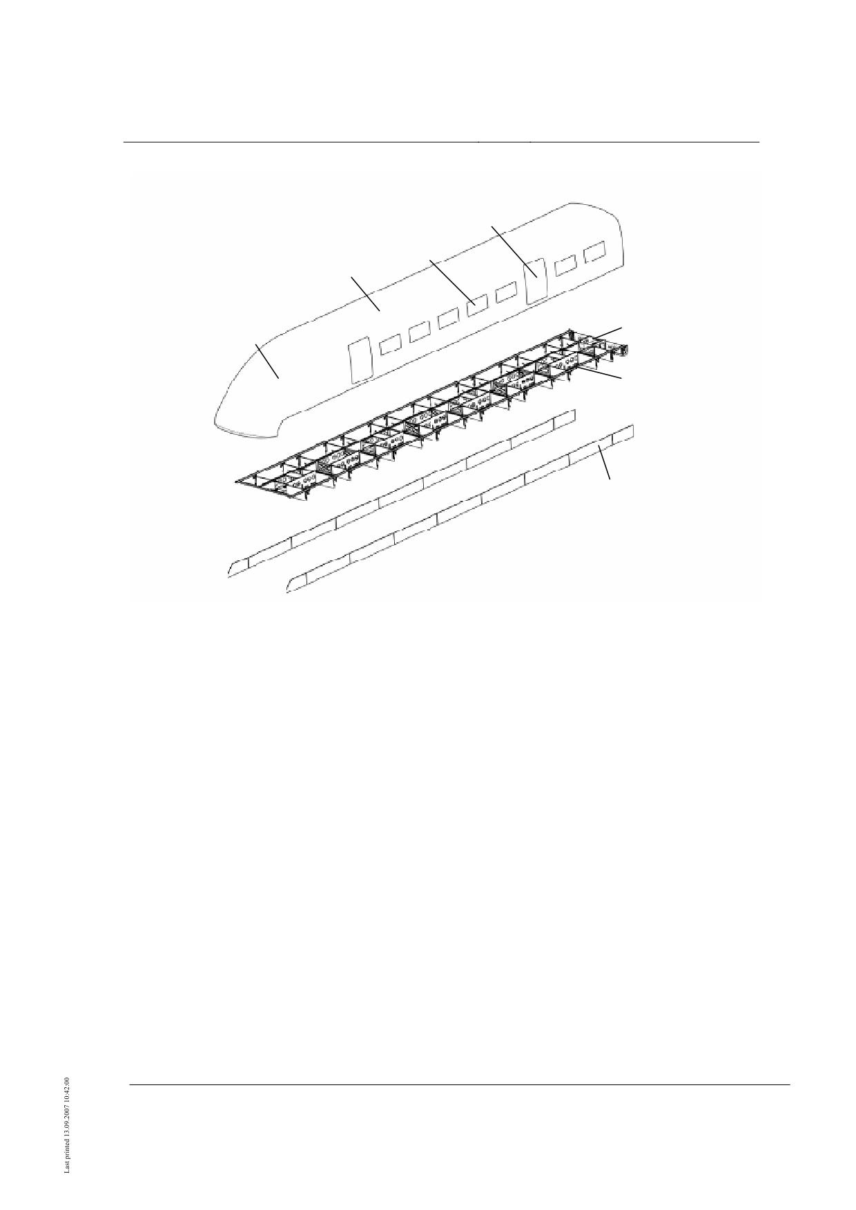
The vehicle section may comprise the body and support/guidance system (Fig. 51). The
bodywork may comprise the body structure with cell and underfloor as well as the body
equipment (Fig. 52).
The cell may comprise the cell structure, nose (end section only) and windows
(Fig. 54).
The cell structure may comprise floor, side walls, windows and roof.
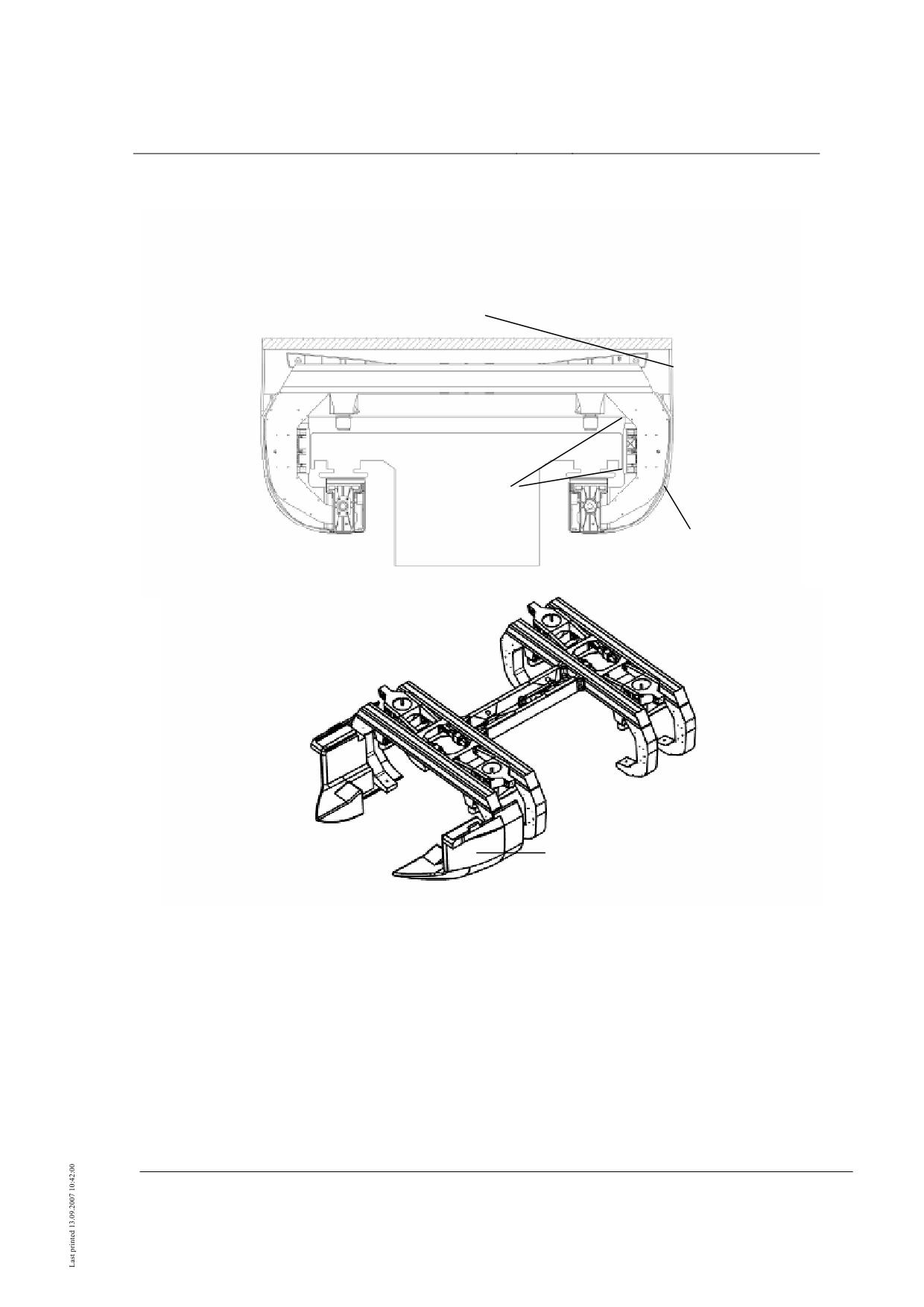
The outer shell may comprise the elements shown in Fig. 55.
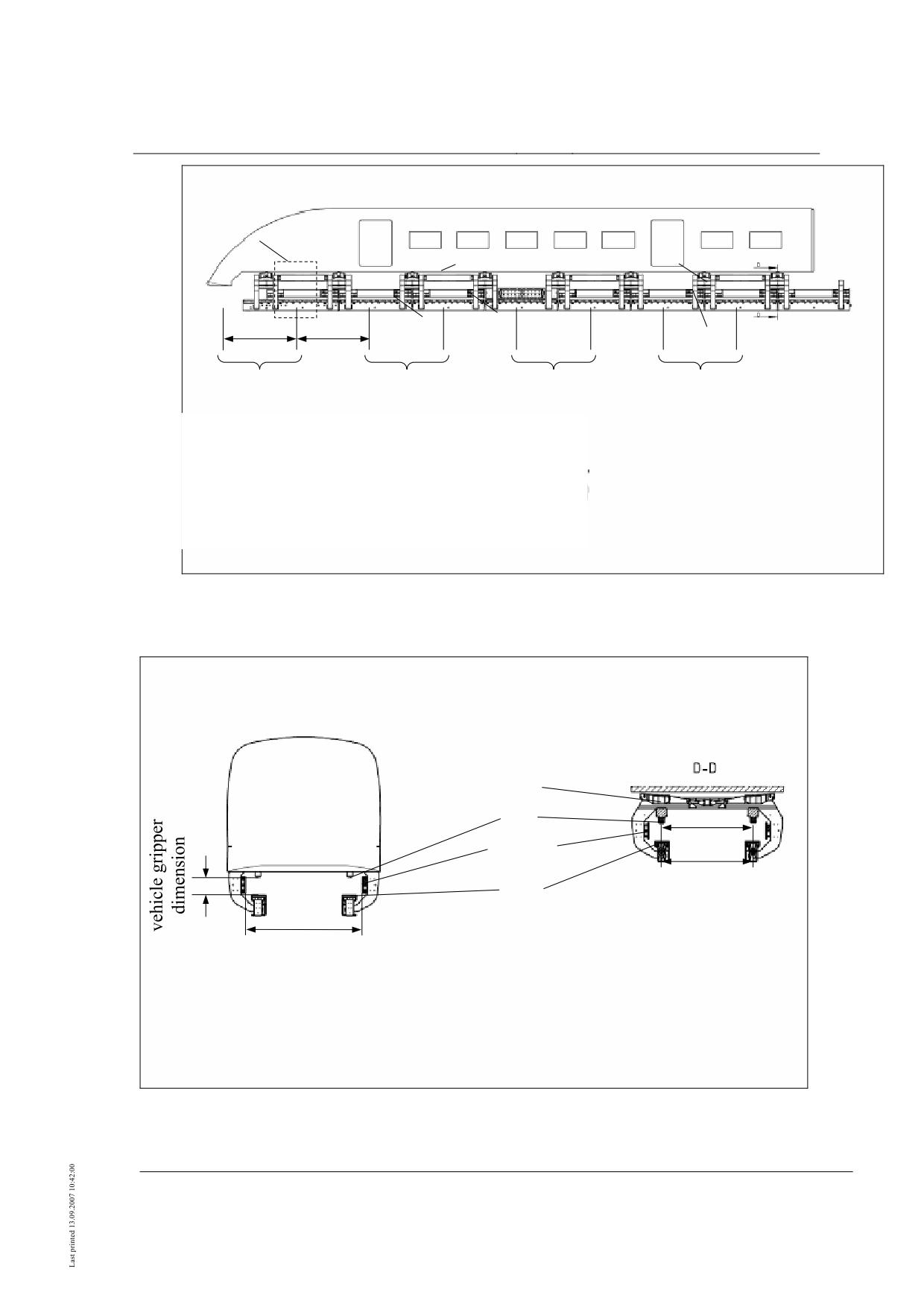
The support/guidance system may comprise the structural assemblies including the shell
(magnetic running gear) and the functional assemblies (electrical and electronic sub-
assemblies) including the on-board energy supply.
The braking equipment may be integrated in the support/guidance system. The brake po-
wer may be generated by brake magnets and removed via the support/guidance structure
(Fig. 56, Fig. 57).
The operational control engineering equipment may be integrated in the body as part of
the technical equipment and have interfaces for the vehicle’s on-board energy supply as
well as for body equipment (e.g. doors) using control and monitoring signals, and for the
support/guidance system (magnetic running gear) including braking equipment. These
interfaces shall be specified between control engineering and vehicle.
Equipment for position fixing for the operation of drive and control engineering may be
integrated in the support/guidance system.
The requirements for position fixing shall be specified from the drive or control enginee-
ring side.
Fahrzeug
Wagen-
Trag- /
kasten
Führsystem
•
Fahrzeug = vehicle; Wagenkasten = body; Trag-/Führsystem = support/guidance system
•
•
Fig. 51: Main subdivision of vehicle
Title
High-speed Maglev System Design Principles
Vehicle Part I, General Requirements
Doc.no.:
67698
Version
White paper
Issue date
15.02.2007
Page 13
High-speed Maglev System
Maglev Technical Commit-
tee
Design Principles
Vehicle
Body
Body structure
Body equipment
Technical equip-
Interior
Cell
Underfloor
ment
equipment
External doors
Interior trim
Cell structure
Mounting structu-
re
Section coupling
Section transition
Nose
Seating
Body bridging
Air conditioning
Luggage racks /
Windows
panel
system
hand rails
Fire safety system
Rescue equipment
Lighting system
Communication /
information equip-
ment
Pneumatic supply
Cargo transporta-
system
tion equipment
Safety equipment
Plumbing unit
(WC)
Radio equipment
Vehicle-integrated equip-
ment for drive and opera-
tional control engineering
Position fixing
*) functions
equipment
•
Fig. 52: Subdivision of body
*)
•
Position and velocity information needed for vehicle operation can be generated by the func-
tional assemblies of the support/guidance system and/or by the position fixing equipment
for the drive and operational control engineering functions.
Title
High-speed Maglev System Design Principles
Vehicle Part I, General Requirements
Doc.no.:
67698
Version
White paper
Issue date
15.02.2007
Page 14
High-speed Maglev System
Maglev Technical Commit-
tee
Design Principles
Vehicle
•
Support/guidance
system
Part IV
Structural assemblies
Functional assemblies
Brake equipment
Position fixing
Support/guidance system
Support/guidance system
Part V
equipment sensors
(magnetic running gear)
Underbody structu-
Support
re
Body coupling/
secondary suspen-
Guidance
sion
Magnets /
On-board energy
magnetic coupling
supply
(incl. battery container)
Equipment for drive
Control /
and operational
Support skids
Monitoring
control engineering
function *)
•
Fig. 53: Subdivision of support/guidance system
*)
•
Position and velocity information needed for vehicle operation can be generated by the func-
tional assemblies of the support/guidance system and/or by the position fixing equipment
for the drive and operational control engineering functions.
Title
High-speed Maglev System Design Principles
Vehicle Part I, General Requirements
Doc.no.:
67698
Version
White paper
Issue date
15.02.2007
Page 15
High-speed Maglev System
Maglev Technical Commit-
tee
Design Principles
Vehicle
external door
window
cell structure
Underfloor area
section coupling
nose
mounting structure
body bridging panel
•
•
Fig. 54: Designations of essential body structure assemblies (examples)
Title
High-speed Maglev System Design Principles
Vehicle Part I, General Requirements
Doc.no.:
67698
Version
White paper
Issue date
15.02.2007
Page 16
High-speed Maglev System
Maglev Technical Commit-
tee
Design Principles
Vehicle
body bridging panel
inner under-
body fairing
outer under-
body fairing
nose fairing rigidly mounted to
underbody
•
Fig. 55: Designations of fairing elements of body and support/guidance system (schematic diagram)
Title
High-speed Maglev System Design Principles
Vehicle Part I, General Requirements
Doc.no.:
67698
Version
White paper
Issue date
15.02.2007
Page 17
High-speed Maglev System
Maglev Technical Commit-
tee
Design Principles
Vehicle
SR
SF
LV
Lsys,TM
Lsys,TM
TM
B
FM
M
1
2
3
4
5
6
7
8
SG1
SG2
SG3
SG4
TM = lift magnet
FM
= guide magnet
BM = brake magnet
SG
= levitation underbody
SR
= levitation frame
SF
= secondary spring
LV
= longitudinal connection
•
•
Fig. 56: Designations of essential assemblies of the support/guidance system (schematic diagram
side view)
SF
TK
ey,TK
FM/BM
ey,TM
TM
lift magnet centre distance ey,TM =
vehicle gau-
support skid centre distance ey,TK
ge
TM = lift magnet
FM
= guide magnet
BM = brake magnet
TK
= support skid
SF
= secondary spring
•
Fig. 57: Designations of essential assemblies and dimensions of the support/guidance system (sche-
matic diagram cross-section)
Title
High-speed Maglev System Design Principles
Vehicle Part I, General Requirements
Doc.no.:
67698
Version
White paper
Issue date
15.02.2007
Page 18
High-speed Maglev System
Maglev Technical Commit-
tee
Design Principles
Vehicle
levitation frame unit
body coupling
traverse module
longitudinal connecti-
on
transverse member
air suspension rocker
Underbody strap
levitation frame
•
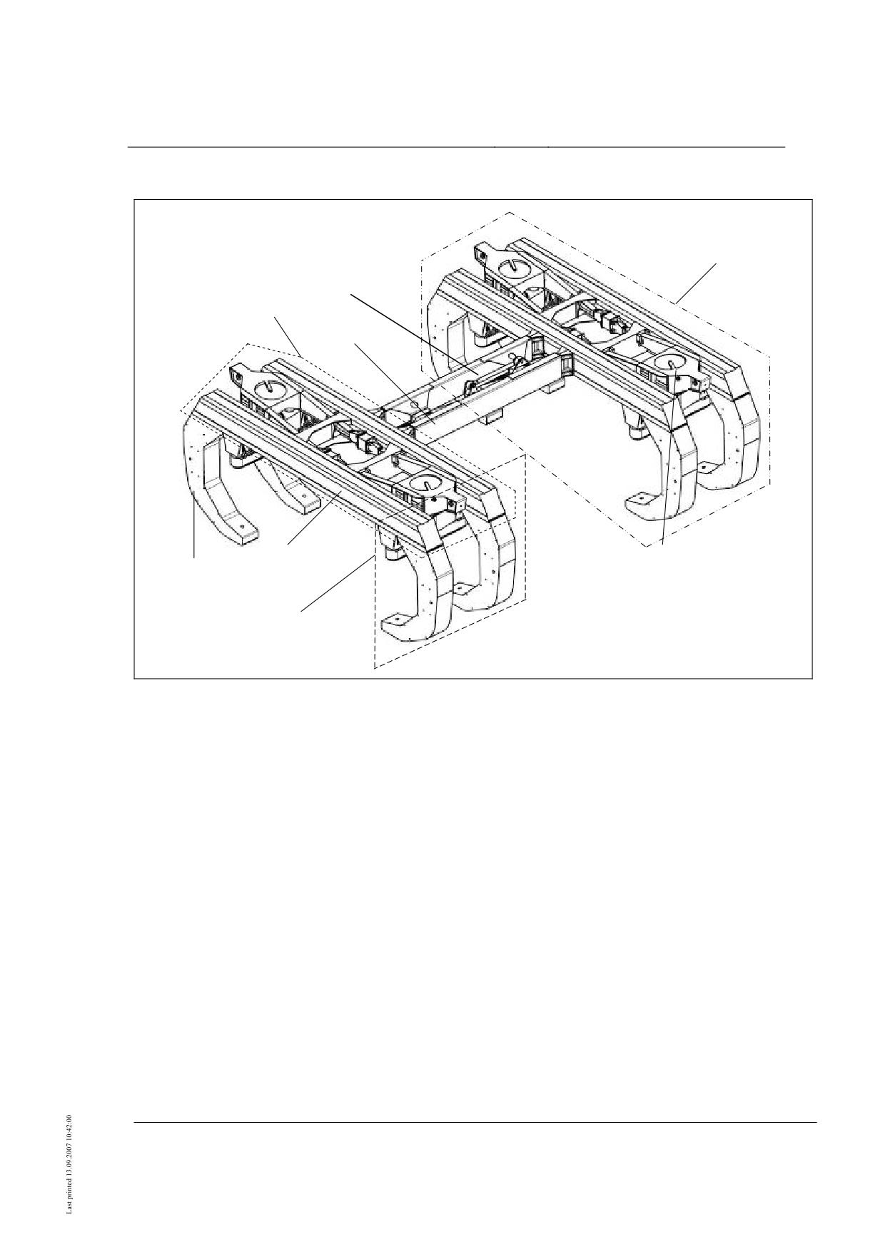
Fig. 58: Designations of essential assemblies of the underbody structure (schematic diagram)
Title
High-speed Maglev System Design Principles
Vehicle Part I, General Requirements
Doc.no.:
67698
Version
White paper
Issue date
15.02.2007
Page 19
High-speed Maglev System
Maglev Technical Commit-
tee
Design Principles
Vehicle
General requirements
Function
•
This is covered by the description in /MSB AG-GESAMTSYS/.
Design of mechanical components
Fundamental design principles
•
The design of load-transmitting structural and fairing parts as well as of externally
mounted and built-in components which do not perform a load-transmitting function shall
be governed by Part II /MSB AG-FZ BEM/.
Collision behaviour
The obstructions defined in /MSB AG-GESAMTSYS/ shall be regarded as a representati-
ve spectrum of collision-causing obstructions which can get into the free space of the ve-
hicle due to environmental or third-party influence.
Collision behaviour shall be determined using numerical simulation calculations und as-
sessed with regard to the impact on vehicle structure and human safety.
In order to obtain the collision behaviour specified in /MSB AG-GESAMTSYS/, chapter
5.4.7.2, the following requirements shall be met:
• no separation of support skids and magnets from the vehicle structure,
• no deformation of cable ducts leading to the failure of safety-related functions,
• no passenger compartment deformation which could pose a threat to personal safety
(deformation with possible threat to personal safety is limited to the end section nose).
• The acceleration acting on the entire vehicle caused by collision in accordance with
defined scenarios shall be tolerated by the assemblies not directly affected by the col-
lision in such a manner that they do not become detached and hence do not affect per-
sonal safety.
The nose space shall not be accessible to passengers. The nose space is not a workplace.2
2 If the nose space is defined as a workplace, the collision scenarios shall take this into
consideration.
Title
High-speed Maglev System Design Principles
Vehicle Part I, General Requirements
Doc.no.:
67698
Version
White paper
Issue date
15.02.2007
Page 20
High-speed Maglev System
Maglev Technical Commit-
tee
Design Principles
Vehicle
Safety requirements
Safety-related functions
A safety certificate taking account of the requirements arising from the project-specific
safety concept (see also /MSB AG-FZ TRAFÜ/ and /MSB AG-FZ BREMS/) shall be
furnished for the following functions:
• Support and guidance,
• Safe braking,
• On-board energy supply.
Other safety-related functions and equipment shall be implemented and certified in accor-
dance with the relevant Standards. See Chapter 0, Annex for definition and certification.
The list of acceptance requirements in Chapter 0, Annex is based on experience gained on
railways and high-speed maglev systems.
/EN 50128/ shall be used for software-implemented safety-related functions.
Fire safety
Fire safety design
In the fire safety design of the vehicles due regard shall be paid to the safety objectives
given in Design Principles Complete System Chapter 5.4.1.1.
Essential fire safety requirements are specified in /MbBO/ (Chapter 4 Vehicles, Section
17 (5). This relates, among other things, to classification of the maglev vehicle according
to DIN 5510-1, fire safety level 4, as well as to the fact that in the event of fire in one ve-
hicle section, people must be protected for at least 30 min. in the other vehicle sections
pending rescue.
The subject-specific regulations from /BrandReg/ shall be used3) to the extent applicable
to the fire safety design and acceptance of maglev vehicles.
The fire safety requirements of the MbBO are covered by /BrandReg/.
Based on /BrandReg/, the maglev vehicle for passenger transportation corresponding to
vehicle type “electric and diesel train units - d” (Chapter 3.2) must be operated with the
classification E4 (Chapter 3.3) if side evacuation is impossible or presents considerable
difficulty on a section of more than 500 m.
3)
The scope of /BrandReg/ relates to rail vehicles. /BrandReg/ does not cover automatically propelled trains. The accep-
tance of maglev vehicles is effected according to Section 6, /MbBO/.
Title
High-speed Maglev System Design Principles
Vehicle Part I, General Requirements
Doc.no.:
67698
Version
White paper
Issue date
15.02.2007
Page 21
High-speed Maglev System
Maglev Technical Commit-
tee
Design Principles
Vehicle
The manufacturer shall draw up a vehicle-related fire safety concept (FSC). This shall be
used as the basis for the fire safety design and certification of the vehicle as well as for the
safety concept in accordance with /MbBO/. Here special allowance shall be made for the
fact that during automatic operation there may be no trained personnel in the vehicle.
One component of the FSC shall be a consideration of fire risks and their possible im-
pacts. Here there shall be an indication of the system-specific interlinking of engineering,
structural and operational measures.
In accordance with /MbBO/, Section 17 (5) (4), the vehicles shall be equipped with auto-
matic fire alarms and portable fire extinguishers. The fire extinguishers shall be kept in
easily accessible locations inside the vehicle and clearly labelled. They shall be distribu-
ted uniformly throughout the length of the vehicle and provided at the ends of the vehicle.
In addition to this, the following areas shall be monitored by fire alarms:
• all areas accessible to passengers,
• the fresh air supply,
• toilets (if present),
• separate engineering areas and separate luggage areas (depending on the fire risk).
When the fire alarm device is activated, the fire alarm shall sound in the vehicle and im-
mediately be transmitted to the operations centre and displayed there. Automatic control
procedures shall be triggered by the fire alarm system installed in the vehicle. For e-
xample, this includes shutting down the air treatment system, if there is one, and trigge-
ring the fire-fighting system.
The engineering equipment of the vehicle shall be designed as far as possible to preclude
the starting of a fire, and so that the impacts with reference to the safety targets defined in
/MSB AG-GESAMTSYS/, Chapter 5.4.1.1 remain acceptable. The specification of the
equipment shall be based on the fire risk analysis, among other things.
With reference to the safety targets defined in the Implementation Bases Complete System
Chapter 5.4.1.1, the requirement with regard to a fire event focussing on “waiting areas”
is fleshed out as follows:
A possible fire event in a vehicle section or in the engineering area shall not lead to loss
of the support, guidance or safe braking functions, or of vehicle stability or vehicle-side
operational control engineering, at least for the period required to reach a suitable stop-
ping place for evacuation4. Over this period and the evacuation period the people waiting
in the vehicle shall be guaranteed conditions acceptable for health.
With regard to minimising the danger to rescue teams, technical installations not associa-
ted with an emergency function shall be shut down. This shall be indicated to the rescue
teams in suitable form. If this is not possible, an appropriate shutdown device shall be
provided on the vehicle.
If necessary, further fire safety measures shall be laid down on a project-specific basis,
depending on the operational function and defined operational boundary conditions.
4 Suitable stopping places for evacuation must be laid down on a project-specific basis.
Title
High-speed Maglev System Design Principles
Vehicle Part I, General Requirements
Doc.no.:
67698
Version
White paper
Issue date
15.02.2007
Page 22
High-speed Maglev System
Maglev Technical Commit-
tee
Design Principles
Vehicle
Fire safety certification
With due regard to the certification requirements listed in /BrandReg/, individual certifi-
cates shall be provided for the following, depending on the transport function (e.g. pas-
senger transport):
•
Fire safety certificate of suitability of materials used
(e.g. seats),
•
Certificates for fire compartmentalising assemblies and functions
(e.g. end doors),
•
Proof of functionality of electrical safety equipment
(e.g. contactors),
•
Proof of functionality of fire detection systems and fire-fighting systems, if present,
•
Proof of the support/guidance function of the high-speed maglev system;
the magnetic support function of the vehicle gives the motivity of the vehicle together
with the operational viability of the drive,
•
Proof of functionality of operational control engineering equipment in the vehicle, see
/MSB AG-GESAMTSYS/, chapter 5.4.1.2.2.1;
the fire safety features of the vehicle’s operational control engineering equipment
shall be covered as part of vehicle fire safety testing,
•
Proof of functionality of communications equipment
(e.g. emergency call equipment),
•
Proof of functionality of emergency exits (e.g. door opening from inside) and rescue
equipment (e.g. ladders),
•
Installation plans for fire safety aids (e.g. fire extinguishers) and communications e-
quipment (e.g. monitors) as well as signs (e.g. pictograms),
•
Proof of third-party rescue facilities (e.g. emergency door opening from outside),
•
Proof of equal safety for measures deviating from regulatory requirements (e.g. mate-
rial requirements),
•
Proof of an adequate time span for passenger evacuation based on the “passenger
compartment” design fire scenario at a continuously increasing heat release rate to a
maximum value of at least 120 kW after 5 min. (minimum fire load of 136 MJ as well
as calorific value at 21 MJ/kg);
a different specification may be agreed on a project-specific basis, depending on
transport function.
Title
High-speed Maglev System Design Principles
Vehicle Part I, General Requirements
Doc.no.:
67698
Version
White paper
Issue date
15.02.2007
Page 23
High-speed Maglev System
Maglev Technical Commit-
tee
Design Principles
Vehicle
Body
Characteristic body bending frequency: see /MSB AG-FZ BEM/, proof of rigidity.
The data specified in /MSB AG-FZ TRAFÜ/ applies to fairing parts and the seals thereof.
Lighting system
Once the on-board electrical system has been inactivated, emergency lighting in the pas-
senger compartment shall be effective for a period of 1 h, see Chapter 0, (III).
The need for persistent escape signs shall be checked on a project-specific basis.
Title
High-speed Maglev System Design Principles
Vehicle Part I, General Requirements
Doc.no.:
67698
Version
White paper
Issue date
15.02.2007
Page 24
High-speed Maglev System
Maglev Technical Commit-
tee
Design Principles
Vehicle
Support/guidance system, braking equipment
The requirements for the support/guidance system are covered in /MSB AG-FZ TRAFÜ/.
The requirements for the braking equipment are covered in /MSB AG-FZ BREMS/.
The requirements for the on-board energy supply from the S/G system, the braking e-
quipment and the operational control equipment integrated in the vehicle are described in
/MSB AG-FZ TRAFÜ/.
Battery containers
The supply and removal of air from the battery container housings shall be monitored. See
/DIN 57510/, /VDE 0510/ for ventilation periods (e.g. overrun after vehicle shutdown).
The intake and outlet battery container ventilation apertures shall be geometrically arran-
ged to preclude battery waste air being sucked in by the air conditioning equipment when
the vehicle is moving or at a standstill. Air conduction shall be guaranteed under all cli-
matic conditions, including winter.
Inadvertent opening of the containers shall be impossible at voltages over 60V.
Title
High-speed Maglev System Design Principles
Vehicle Part I, General Requirements
Doc.no.:
67698
Version
White paper
Issue date
15.02.2007
Page 25
High-speed Maglev System
Maglev Technical Commit-
tee
Design Principles
Vehicle
Annex Weighing the Maglev Vehicle
Preparation
A project-specific test specification shall be submitted before taking the measurements for
the determination of weight.
This serves the purpose of defining the prerequisites, sequence, basic conditions and type
of documentation prior to measurement.
The test specification shall include the following essential points:
• Objective and backg2round of measurements,
• Definition of essential basic conditions (e.g. separate section couplings etc.),
• Description of test method (sequence, plausibility checks etc.),
• Planning variables for the trial (e.g. time requirement, boundary conditions in conduct
of testing),
• Description of measuring equipment (accuracy class, calibration),
• Description of requisite documentation (tables, photographs etc.).
Terms of reference and boundary condi-
tions
Different terms of reference may apply to the determination of weight for maglev vehic-
les, depending on target definition and measurement conditions (e.g. section coupling
condition / measurement below support skid or back of support magnet).
To determine the vehicle weight for maglev vehicles, the measurements shall be taken at
the individual levitation frames of the left and right side of the vehicle in each case.
Two categories may be taken into consideration for the condition of the vehicle during
measurement:
• Measurement of vehicle weight without section coupling engaged,
• Measurement with section coupling engaged, the supporting forces transmitted by the
section coupling then having to be measured as well.
The following boundary conditions shall be met in order to ensure a representative weight
determination:
• The vehicle shall be in the equipped condition (at least with active levelling control).
• The vehicle shall be in the weigher, i.e. the permissible deviations within the support
skid bottom edge reference plane are ± 2 mm relative to the skid linings when new.
This tolerance applies in relation to the levitation frame currently to be measured, at
least to all the levitation frames assigned to the same pneumatic spring circuit, and to
Title
High-speed Maglev System Design Principles
Vehicle Part I, General Requirements
Doc.no.:
67698
Version
White paper
Issue date
15.02.2007
Page 26
High-speed Maglev System
Maglev Technical Commit-
tee
Design Principles
Vehicle
the levitation frames assigned to the adjacent pneumatic spring circuit in the current
section belonging to the same pneumatic spring circuit in the adjacent section, the last
requirement only relating to the case when measurement is carried out without a sepa-
rated section coupling. These conditions apply in the further course of the text if this
tolerance is named.
• The whole train must have levitated completely at least once prior to measurement, so
that internal distortion forces are reduced.
• The bellows present in section transition areas shall be dismantled during measure-
ment in order to preclude any force transmission through same.
• When weight is determined without first detaching the section coupling, the coupling
forces transmitted shall also be measured.
• During sequential measurement, i.e. when the weight is not measured simultaneously
at all levitation frames, sufficient repeat measurements shall be carried out in order to
preclude the influence of any existing distortions or other error sources.
• The tolerance of the measuring equipment shall not exceed ± 2 %.
The weight of the vehicle may be measured at various locations.
Two commonly used methods and the boundary conditions specifically to be taken into
account are described below.
As a rule measurement is accompanied by a weight statement tracking the changes cau-
sed by items fitted and/or removed.
Any deviation from the specified procedure before or during measurement shall be agreed
on a project-specific basis.
Title
High-speed Maglev System Design Principles
Vehicle Part I, General Requirements
Doc.no.:
67698
Version
White paper
Issue date
15.02.2007
Page 27
High-speed Maglev System
Maglev Technical Commit-
tee
Design Principles
Vehicle
Measurement below support skids
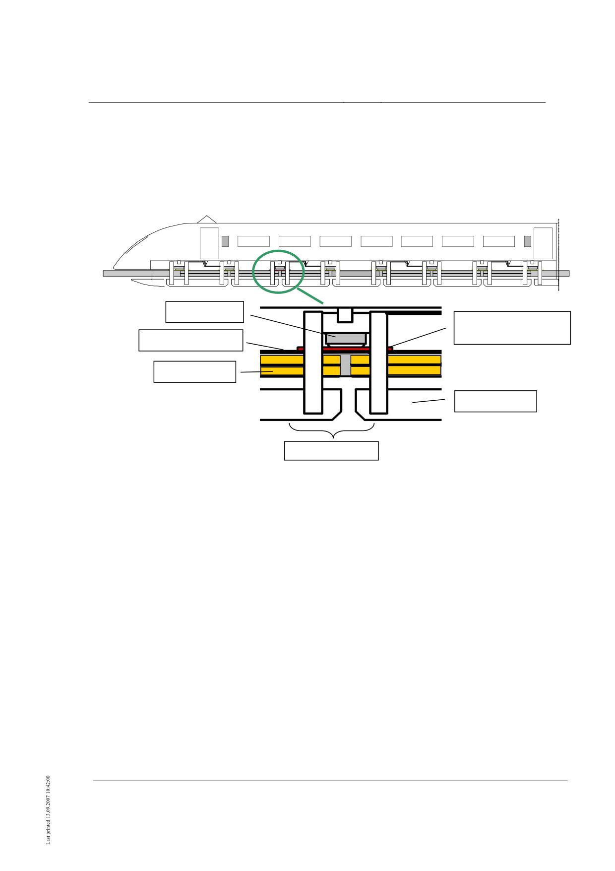
When measurements are taken below the support skids, the measuring equipment must be
located between the support skid and sliding face or top guideway edge with the vehicle
lowered.
support skid
measuring equipment
and equalising plate
sliding face plane
guide magnet
support magnet
levitation frame
•
Fig. 59: Schematic diagram for the method of measurement beneath the support skid
During measurement, care shall be taken to comply with the maximum deviation of ±
2 mm in the plane of the support skid bottom edges. It shall also be ensured that the level-
ling control is in the steady state.
The following applies to measurement:
• For simultaneous measurement at all levitation frames of the section, measuring e-
quipment is placed beneath the support skids.
• For sequential measurement, the section is completely packed underneath with equali-
sing plates which are successively exchanged for measuring equipment of the same
height.
In the aforementioned measurement method beneath the support skids it may be possible
to achieve easier introduction of the measuring equipment (weighing plates between sup-
port skids and guideway) with a different parameter set (smaller support gap).
Title
High-speed Maglev System Design Principles
Vehicle Part I, General Requirements
Doc.no.:
67698
Version
White paper
Issue date
15.02.2007
Page 28
High-speed Maglev System
Maglev Technical Commit-
tee
Design Principles
Vehicle
Measurement beneath the backs of the
support magnets
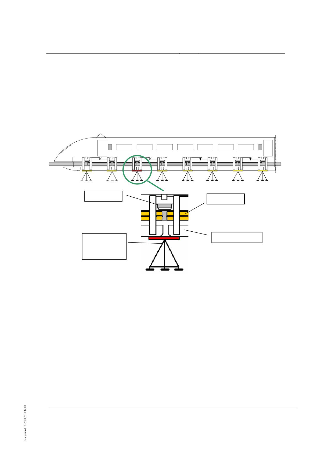
When determining the vehicle weight beneath the backs of the support magnets, the mea-
suring equipment must be located between support magnet bottom edge and a support
(e.g. prop). In this measurement method the vehicle shall be lowered onto the supports
from the levitating state. It shall be ensured that the support skids have no contact with the
guideway during measurement.
support skid
guide magnet
support magnet
support with
measuring e-
quipment
•
•
•
•
Fig. 60: Schematic diagram of the method of measurement beneath the backs of the support magnets
Care shall be taken not to exceed a deviation of ± 2 mm in the plane of the support skid
bottom edges during measurement. Here it shall also be ensured that the levelling control
is in the steady state.
It is recommended that reference marks be introduced in order to comply with the tole-
rances relative to the support skid bottom edges. However these should not be located in
areas of which the geometric position (relative to the bottom edge of the support skids) is
influenced by the introduction of a load to the underbody straps.
Title
High-speed Maglev System Design Principles
Vehicle Part I, General Requirements
Doc.no.:
67698
Version
White paper
Issue date
15.02.2007
Page 29
High-speed Maglev System
Maglev Technical Commit-
tee
Design Principles
Vehicle
The following applies to measurement:
• For simultaneous measurements at all levitation frames of the section, measuring e-
quipment shall be placed at an appropriate height beneath the backs of the support
magnets and the vehicle lowered on top.
• For sequential measurement, the section shall be supported completely at the ap-
propriate height beneath the backs of the support magnets. To determine the weight at
individual levitation frames, the supports shall be successively replaced by a support
with integrated measuring equipment.
Supplementary measured quantities
In order to ensure that recording of the relevant influencing factors is as complete as pos-
sible when taking weight measurements, the additional measurement of the pneumatic
spring pressures and the vehicle’s levelling position is advisable.
When determining the vehicle’s weight and simultaneously measuring the coupling force,
it is advisable to take further measurements with an extra weight (mass > 500 kg) at vari-
ous x-positions in the body, so as to mathematically simulate the influence of a variable
payload on the support behaviour of the section coupling.
Evaluation
The evaluation of the weighing shall list the weights determined at all levitation frames, in
each case separately by left and right side of the vehicle. This data shall be supplemented
by the calculated total weight of the individual sections. For a visual representation of the
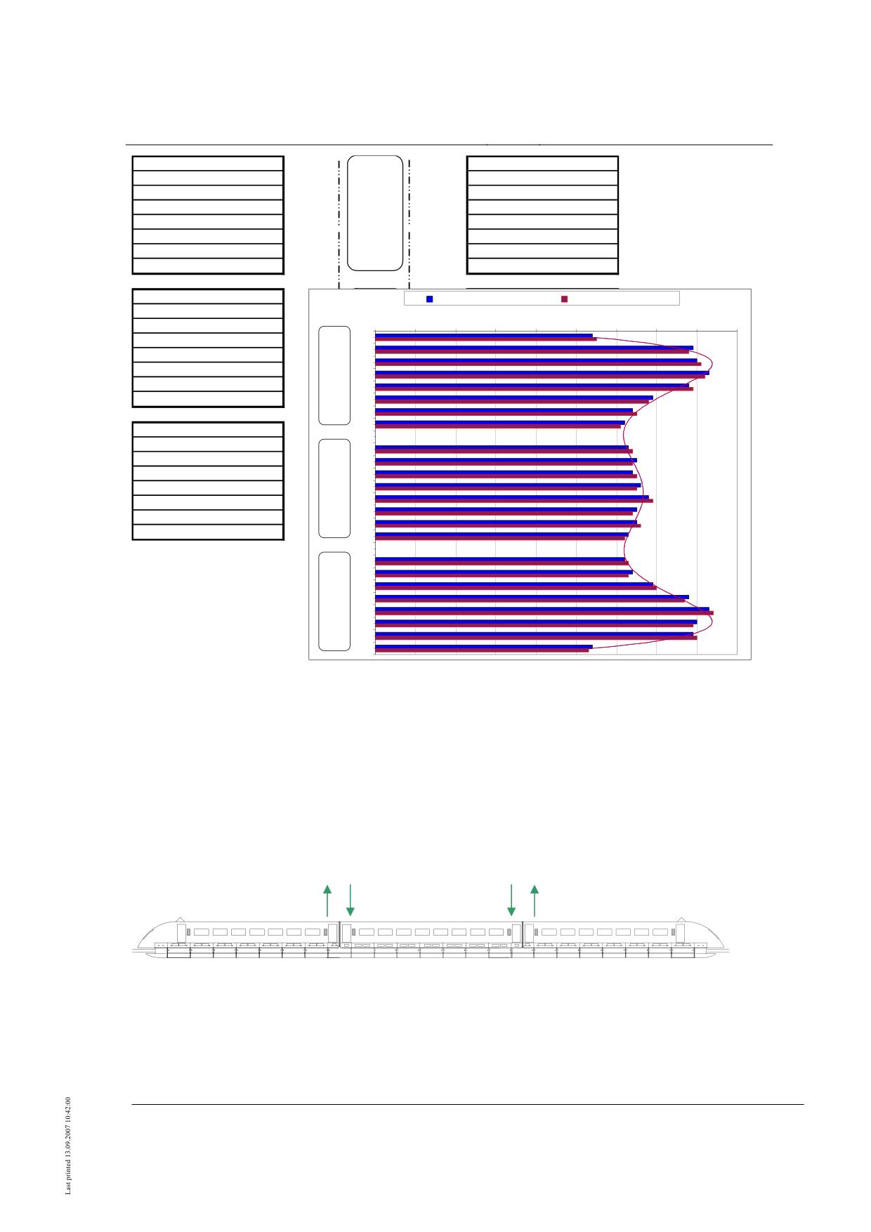
weight distribution over the total length of the vehicle, a supplementary schematic dra-
wing similar to Fig. 61 is recommended.
Title
High-speed Maglev System Design Principles
Vehicle Part I, General Requirements
Doc.no.:
67698
Version
White paper
Issue date
15.02.2007
Page 30
High-speed Maglev System
Maglev Technical Commit-
tee
Design Principles
Vehicle
E1-SR1-L
2700 kg
2750 kg
E1-SR1-R
E1-SR2-L
3950 kg
3900 kg
E1-SR2-R
E1-SR3-L
4000 kg
4050 kg
E1-SR3-R
E1-SR4-L
4150 kg
E1
4100 kg
E1-SR4-R
E1-SR5-L
3900 kg
56900 kg
3950 kg
E1-SR5-R
E1-SR6-L
3450 kg
3400 kg
E1-SR6-R
E1-SR7-L
3200 kg
3250 kg
E1-SR7-R
E1-SR8-L
3100 kg
3050 kg
E1-SR8-R
M-SR1-L
3150 kg
Linke Fahrzeugseite
Rechte Fahrzeugseite
M-SR2-L
3250 kg
0 kg
500 kg
1000 kg
1500 kg
2000 kg
2500 kg
3000 kg
3500 kg
4000 kg
4500 kg
M-SR3-L
3200 kg
E1-1
M-SR4-L
3300 kg
E1-2
M-SR5-L
3400 kg
E1-3
M-SR6-L
3250 kg
E 1
E1-4
M-SR7-L
3250 kg
E1-5
M-SR8-L
3150 kg
E1-6
E1-7
E1-8
E2-SR1-L
3100 kg
E2-SR2-L
3200 kg
M-1
E2-SR3-L
3450 kg
M-2
E2-SR4-L
3900 kg
M-3
M
M-4
E2-SR5-L
4150 kg
M-5
E2-SR6-L
4000 kg
M-6
E2-SR7-L
3950 kg
M-7
E2-SR8-L
2700 kg
M-8
E2-1
E2-2
E2-3
E 2
E2-4
E2-5
E2-6
E2-7
E2-8
•
Linke Fahrzeugseite = left side of vehicle; Rechte Fahrzeugseite = right side of vehicle
•
Fig. 61: Example of measurement results for a vehicle with three sections in the form of a table and
chart (hypothetical measured values)
A schematic diagram like the example shown in Fig. 62 is recommended for giving the
coupling supporting forces and their effective direction. This shall clearly show how the
force acts on the different components.
7.6 kN
8.1 kN
E1
M
E2
•
Fig. 62: Example of a schematic diagram for the coupling supporting forces and their effective direc-
tion on a vehicle with three sections
•
(Arrows show the direction of force with which the sections act on the coupling bolts / hypo-
thetical measured values)
Title
High-speed Maglev System Design Principles
Vehicle Part I, General Requirements
Doc.no.:
67698
Version
White paper
Issue date
15.02.2007
Page 31
High-speed Maglev System
Maglev Technical Commit-
tee
Design Principles
Vehicle
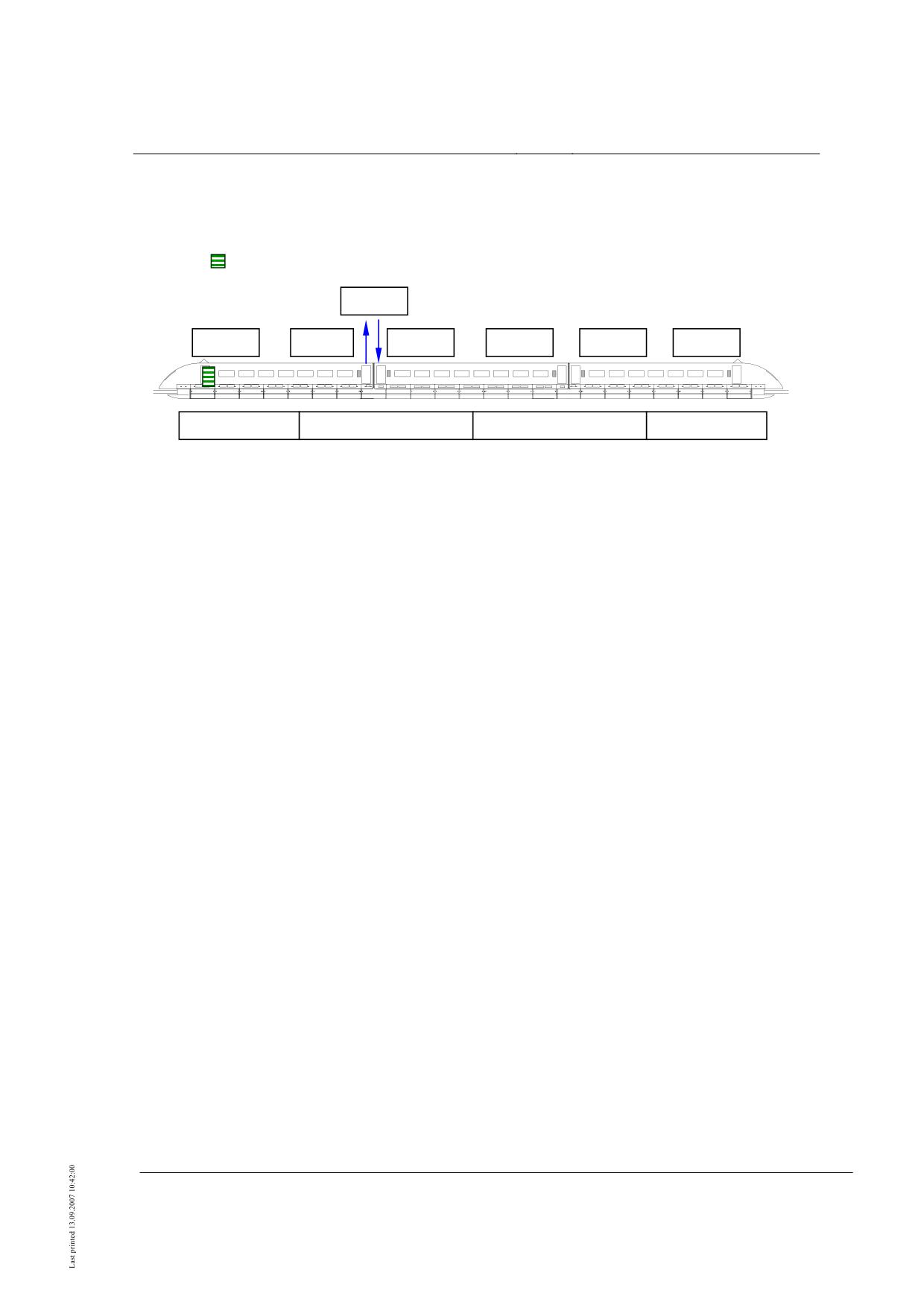
If the weight measurements are supplemented by the quantities given in Chapter 0, a re-
presentation according to the schematic diagram illustrated as an example in Fig. 63 is
recommended. The graphics should show the pneumatic spring pressures, the levelling
position of the body, the measured coupling supporting force and the position of the extra
weight (
).
9.7 kN
-1.3mm
0.7mm
0.9mm
0.4mm
0.2mm
0.4mm
E1
E2
7.00 bar
5.10 bar
5.25 bar
7.10 bar
•
Fig. 63: Example of a schematic diagram showing the supplementary measured quantities for pneu-
matic spring pressure, levelling position, coupling supporting force and position of the extra weights
on a vehicle with three sections
•
(showing individual measurement in which one coupling force is measured / hypothetical
measured values)
Documentation
The documentation of weighing serves to ensure the reproducibility of measurement re-
sults.
Documentation shall contain the elements below:
• Weighing sequence (particularly for sequential measurement of individual levitation
frames) and status of section couplings,
• Note on the weight of the missing transition magnets if individual sections are measu-
red,
• Documentation of the vehicle’s equipment status using a list and/or photographs (mis-
sing or additional components etc.),
• Representation of results of additional measurements for plausibility testing,
• Calibration results of measuring equipment.
Title
High-speed Maglev System Design Principles
Vehicle Part I, General Requirements
Doc.no.:
67698
Version
White paper
Issue date
15.02.2007
Page 32
High-speed Maglev System
Maglev Technical Commit-
tee
Design Principles
Vehicle
Annex List of requirements for acceptance (example)
Requirements for the acceptance of high-speed maglev system vehicles in accordance
with Section 6 (1) /MbBO/.
The attached checklist serves as an example. It shall be agreed on a project-specific basis
between the approval authority, the high-speed maglev system operator and the vehicle
supplier, together with Standards and test and certification procedures to be used.
The list of requirements for acceptance included in this Chapter is based on experience
gained on railways and high-speed maglev systems. It supplements /MSB AG-
NORM&RILI/.
In the “Documents” column the certification documents relating to the relevant features
shall be named on a project-specific basis.
Overview:
I.
General
II.
Basic vehicle parameters
III.
Vehicle requirements
IV.
Construction and fabrication requirements
V.
Body requirements
VI.
Support/guidance system
VII. Software
VIII. Braking equipment
IX.
Systems subject to monitoring
X.
Interior equipment
XI.
On-board energy supply / electrical equipment
XII. Controls and communications, other safety equipment
XIII. Environmental protection provisions
XIV. Occupational safety / personal safety
XV. Fire safety
Title
High-speed Maglev System Design Principles
Vehicle Part I, General Requirements
Doc.no.:
67698
Version
White paper
Issue date
15.02.2007
Page 33
High-speed Maglev System
Maglev Technical Committee
Design principles
Vehicle
I.
General
1
Filing of applica-
Filing of application
Including a declaration as to the section or route
tion
network on which the vehicle will be used within the
scope of AMbG.
2
Declaration on
Declaration that no deviation from the stan-
Section 3 MbBO
compliance with
dards of the MbBO is intended and that
Section 5 MbBO
MbBO
MbBO standards will be complied with.
3
Declaration on
Declaration that no deviation from the ac-
Section 3 MbBO
compliance with
cepted code of engineering practice is in-
accepted code of
tended.
engineering prac-
In the event of deviations: furnish approval
tice
authority with proof of identical safety
Section 3 (2) sentence 2 MbBO
4
Declaration of
Safety concept
Section 23 MbBO
Implementation of the safety concept for the section
compliance with
(incl. rescue concept)
or route network on which the vehicle will be opera-
all safety concept
ted.
Safety targets
requirements
In addition to the requirements directly contained in
Proof of implementation of the measures in
the MbBO and the accepted code of engineering
the vehicle with detailed reference to the
practice, the safety concept according to Section 23
corresponding reference in the safety con-
MbBO may give rise to further requirements from a
cept
maglev vehicle. In part these requirements first crea-
te the prerequisite for the application of a Standard
(e.g. specification of a safety requirement level con-
forming to DIN EN 50128).
5
Complete system contract specification
Analogous to VwV Section 32 EBO
6
Performance specification
Analogous to VwV Section 32 EBO
7
Certificate of conformity with the principles
Principles and procedures for the compilation
and procedures for compilation of the main-
of maintenance programs in accordance with
tenance programs
Section 8 (2) MbBO
Title
High-speed Maglev System Design Principles
Vehicle Part I, General Requirements
Doc.no.:
67698
Version
White paper
Issue date
15.02.2007
Page 1
High-speed Maglev System
Maglev Technical Committee
Design principles
Vehicle
8
Interface documents /
Design Principles Complete System /
Complete system contract specification (5),
Design Principles of further sub-systems
Complete system performance specification
(6)
9
Certification of manufacturer’s / supplier’s
DIN ISO 9001
The approval authority may conduct a random check
quality management system
on the effectiveness of the quality management sys-
tem.
Title
High-speed Maglev System Design Principles
Vehicle Part I, General Requirements
Doc.no.:
67698
Version
White paper
Issue date
15.02.2007
Page 2
High-speed Maglev System
Maglev Technical Committee
Design principles
Vehicle
II.
Basic vehicle parameters
1
General techni-
Technical data on vehicle
cal specificati-
Performance specification
ons
Application for acceptance Section 6
MbBO
1.1
Designation of vehicle type
1.2
Vehicle no.
1.3
Serial no.
1.4
Year of manufacture
1.5
Manufacturer
1.6
Owner/operator
2
Driving capacity
2.1
not applicable
2.2
Operating concept from contract specifica-
tion / performance specification
Maximum velocity,
See Design Principles Complete System
Operational control velocity
Annex 1
2.3
Vehicle length
2.4
Unladen weight
See Chapter 0, Annex Weighing
Analogous to TETF Practice
Skid loads
Loads on section couplings
Position of centre of gravity
2.5
Permissible total weight
Title
High-speed Maglev System Design Principles
Vehicle Part I, General Requirements
Doc.no.:
67698
Version
White paper
Issue date
15.02.2007
Page 3
High-speed Maglev System
Maglev Technical Committee
Design principles
Vehicle
2.6
Max. vehicle weight per unit of length
2.7
Number of places (number of seats and
standing places), persons per unit of area
2.8
Number of compartments
2.10
Number of toilets, washrooms
2.11
Number of other spaces (e.g. luggage sto-
wage spaces)
2.12
Number of vehicle sections
2.13
Levitation frames: arrangement and design,
number of levitation frames, distance bet-
ween levitation frames
2.14
Max. loads acting on support and guidance
Design Principles Vehicle Part II Design
Shall be derived from contract specification and
units
complete system performance specification
2.15
Drive power
see Point I, (8)
On a project-specific basis, see contract specification
and complete system performance specification
2.16
Smallest practicable radius
Design Principles Complete System
Title
High-speed Maglev System Design Principles
Vehicle Part I, General Requirements
Doc.no.:
67698
Version
White paper
Issue date
15.02.2007
Page 4
High-speed Maglev System
Maglev Technical Committee
Design principles
Vehicle
III.
Vehicle requirements
1
Vehicle limitati-
Drawing, proof in accordance with /MSB
Section 17 (3) MbBO in conjunction with
Based on the methodology of UIC 505.
on, vehicle ki-
AG-BEM/
Annex to Section 14 MbBO and IB Vehicle
The expert report on kinematic vehicle limitation
nematics
Part III,
should contain the following statement: “I hereby
Section 14 MbBO
confirm that the vehicle loading gauge was calcula-
ted (according to …..). The loading gauge for the
kinematic space requirement of the vehicle shown in
the Annex to Section 14 MbBO is not exceeded, not
even in cases where ….”.
Certificate according to IB Vehicle Part III
2
Signal equipment
Drawing/ description:
DS / DV 301 “Signal book”
Deviations shall be agreed on a project-specific basis
- head light
- release signal
3
Vehicle addres-
Drawing/ description; list of signs and
UIC 640
Deviations shall be agreed on a project-specific basis
ses
addresses
ISO 7001:1990 (pictograms)
4
Vehicle-side gap
Performance specification
Section 15 MbBO
If present
bridging in em-
DIN EN 14752 (Railway applications -
Ensure coordination with platform doors (Section 15
barkation area
bodyside entrance systems), compliance with
MbBO)!
TSI-PRM
5
Malfunction and
Number, description, drawing with position
Section 18 (3) MbBO
Differentiation in rescue concept according to Secti-
emergency con-
of emergency exits
on 23 MbBO:
cept / emer-
Rescue concept according to Section 23 MbBO lays
gency exit con-
DIN 5510
down emergency concept (relative to complete sys-
cept
Safety concept
tem).
EBA Manual Fire Safety in Passenger Trans-
port Systems of the Federal Railways
As part of vehicle acceptance pursuant to Section 6
MbBO, checking to see whether the measures within
Title
High-speed Maglev System Design Principles
Vehicle Part I, General Requirements
Doc.no.:
67698
Version
White paper
Issue date
15.02.2007
Page 5
High-speed Maglev System
Maglev Technical Committee
Design principles
Vehicle
the safety concept (and rescue concept) as well as
Signage concept
/BrandReg/
the statutory requirements and accepted code of
engineering practice have been implemented in the
actual vehicle.
6
Pressure tight-
Contract specification
UIC 660
Shall be derived for subsequent implementation
ness / Pressure
from contract specification and complete system
Performance specification
/MSB AG-GESAMTSYS/
viability
performance specification
7
Pressure wave
Contract specification
Shall be derived for subsequent implementation
effects
from contract specification and complete system
Performance specification
performance specification
8
Climatic envi-
Contract specification
In accordance with /MSB AG-Environment/
To be stipulated on a project-specific basis.
ronmental condi-
Performance specification
Official explanatory notes to Section 17 MbBO: the
tions
vehicles shall meet all the operating and environ-
mental conditions to be covered
9
Aerodynamics
Performance specification
En 14067,
UIC 660,
DB RIL 807-04 (side wind)
Title
High-speed Maglev System Design Principles
Vehicle Part I, General Requirements
Doc.no.:
67698
Version
White paper
Issue date
15.02.2007
Page 6
High-speed Maglev System
Maglev Technical Committee
Design principles
Vehicle
IV.
Construction and fabrication requirements
1
Bolted joints
Drawings/ descriptions/ testing of structure
Environmental requirements in the relevant
Securing of bolted joints
for proof against loss;
installation space
Proof against loss is particularly important in maglev
Performance specification
DIN 25201
vehicles, as the guideway gradient is considerably
greater than in railways and the velocities are also
Setting the scope of certification and certi-
higher as a rule.
fication procedure (if necessary experimen-
tally)
2
Rivet joints
Drawings
Project-specific certification required.
Setting the scope of certification and certi-
Frictional connection / positive connection (depen-
fication procedure (if necessary experimen-
dent on rivet type and material pairing)
tally)
Test report on relevant component tests
3
Welded as-
Drawings
“Administrative Directive for requirements
Particularly DIN 6700 Part 2
semblies
for the welding of rail vehicles and parts
Æ EBA-recognised specialist welding companies!
within the purview of the EBA”;
DIN 6700
4
Adhesive joints
Drawings/ descriptions/strength certificates/
DIN 6701, Part 1 and 2
Manufacturing procedure for vehicle const-
DVS Fact sheet M 1618 (01/2002 edition)
For elastic thick layer adhesive joints (nose)
ruction (bodywork mechanics)
Elastic thick layer adhesion in rail vehicle
construction
V.
Bodywork requirements
Title
High-speed Maglev System Design Principles
Vehicle Part I, General Requirements
Doc.no.:
67698
Version
White paper
Issue date
15.02.2007
Page 7
High-speed Maglev System
Maglev Technical Committee
Design principles
Vehicle
1
Determination of
Mathematical proof and proof by measure-
The measurement method is described in
vehicle weight
ment
Chapter 0 of this document.
2
Vehicle construc-
General drawing (shell and levitation un-
tion
derbody) with dimensioning; vehicle body
measurement (drawing and measurement
sheet)
Statement of materials used (load transmit-
ting parts)
Arrangement of individual components
Jointing procedures
3
Determination of
Mathematical or experimental proof
Each vehicle section
position of centre
of gravity
4
Representation of
Drawings,
All lifting points shall, where applicable, be inde-
lifting points
Transportation requirement
libly marked on the hardware concerned
5
Clearance at ends
Drawing
UIC 521, Couplings.
If present
of vehicle
Description clearance at coupling end
6
Bodywork of one
Proof relating to collision scenarios
Contract specification/performance specifica-
Section 17 (2) MbBO: “The impact of the vehicle on
section including
tion
the guideway shall not exceed the impact allowed
equipment
for during guideway design”.
Section 17 (2) MbBO
The impact shall be derived for subsequent imple-
MSB document Basis of Dimensioning IB
mentation from contract specification and complete
Vehicle Part II, IB Complete System
system performance specification.
7
Coupling of
Description of construction, mathematical
Section 20 (2) MbBO
sections
and experimental proof
UIC 572
IB Vehicle Part II
Title
High-speed Maglev System Design Principles
Vehicle Part I, General Requirements
Doc.no.:
67698
Version
White paper
Issue date
15.02.2007
Page 8
High-speed Maglev System
Maglev Technical Committee
Design principles
Vehicle
The measurement method for determining the
loading of the section coupling is described in
Chapter 0 of this document.
8
Externally moun-
Drawing/ description/ proof of structural
IB Vehicle Part II
Example: radome
ted components
durability and proof against loss under the
environmental conditions ruling at the in-
stallation location
Contract specification/ performance speci-
fication
9
Transitions
Drawing/ description
Contract specification / performance specifi-
cation
10
External panes
Section 18 (1) MbBO
10.1
Windscreens
Drawing / description
UIC 651
Criteria:
(where present)
Optical quality
TSI HGV Vehicles: Chapters 6.3.2 and
De-icing, condensation prevention.
4.3.19
Windscreen cleaning effected according to pro-
ject-specific terms of reference.
Projectile strike
10.2
Side windows
Drawing / description
UIC 564 - 1
UIC 564-1 does not cover the HGV velocity range.
HGV side windows are therefore tested under PA-
UIC 660
1300, 2005 edition DB Systems engineering test
UIC 567
program for window systems. Testing is conducted
with reference to UIC 564-1.
BN 918511
The load level and number of load cycles shall be
PA-1300, DB Systems engineering test pro-
agreed on the basis of the usage spectrum (load
gram for window systems, 2005 edition.
collective) and meaningful additions.
11
Doors
Section 18 (1) MbBO
Title
High-speed Maglev System Design Principles
Vehicle Part I, General Requirements
Doc.no.:
67698
Version
White paper
Issue date
15.02.2007
Page 9
High-speed Maglev System
Maglev Technical Committee
Design principles
Vehicle
11.1
Entrance doors
Safety concept
Section 18 (2) (1) and (2) MbBO
Cf. also official explanatory notes on Section 18
MbBO: “Door locking according to paragraph 2 is of
Departure preparation procedure
VDV 111
particular importance at high velocities.”
Drawing / description
DIN EN 14752
Automatic door locking when the vehicle is not
Proof of safety functions under given envi-
UIC 560
lowered shall be defined by means of risk analysis.
ronmental conditions according to contract
UIC 566
Description of the interaction of vehicle door, plat-
specification
form door and gap bridging.
DIN 32974 (Acoustic signals)
11.2
Section transition
Drawing / description
Section 17 (5) (3) MbBO
If necessary Section 17 (5)(3) MbBO: 30 min -
doors
criterion
Safety concept
if necessary DIN 5510
Proof of safety functions
VDV 111
DIN EN 14752
UIC 560
11.3
WC doors
Drawing / description
12
Handles, hand
Drawing / description
According to pertinent Railway Standards
rails, steps
Fastening devi-
Drawing / description
Movement of containers may be safety-related
13
ces for luggage
containers
Title
High-speed Maglev System Design Principles
Vehicle Part I, General Requirements
Doc.no.:
67698
Version
White paper
Issue date
15.02.2007
Page 10
High-speed Maglev System
Maglev Technical Committee
Design principles
Vehicle
VI.
Support/guidance system
1
Support/guidance
Proof of static and dynamic strength (ma-
Implementation |Basis Vehicle Part IV Sup-
Nominal values shall be set on a project-specific
structure (levita-
thematical and / or experimental)
port /guidance system & Part II Design
basis.
tion frame, sup-
Details of materials used, particularly sup-
port and guidan-
port skids:
ce magnets)
Thermal behaviour
Support skids
etc.
Mechanical behaviour, breaking strength
Wear
Coefficient of friction support skid / sliding
face
2
Functions of
Safety concept
Design Principles Vehicle Part IV Support
levitation engi-
/guidance system
Drawings/ descriptions:
neering:
Gap measurement units
safe support
function,
Magnet controls
safe guidance
Failure behaviour
function
in conjunction
with safe on-
board energy
supply
3
Vertical loads,
Proof that max. vertical loads plus transver-
Design Principles Part IV T/F System and
transverse forces,
se and longitudinal forces are not exceeded
Part II Design
longitudinal
forces
Title
High-speed Maglev System Design Principles
Vehicle Part I, General Requirements
Doc.no.:
67698
Version
White paper
Issue date
15.02.2007
Page 11
High-speed Maglev System
Maglev Technical Committee
Design principles
Vehicle
VII. Software
1
Classification of
Classification as
EN 50128
Examples:
software
Non safety-related software, safety
Support /guidance system
requirement level (SRL) = 0
On-board energy supply
or
Braking equipment
Safety-related SRL > 0
EN 61508
Door controls
Air conditioning equipment
Fire safety equipment
Communications equipment
2
Safety-related
e.g.:
Safety concept
functions
Brakes,
EN 50128
Embarkation and debarkation,
Guide for the application of EN 50128 to rail
vehicles (09/2005 Edition)
Interfaces to train protection etc.
all equipment which
o engages with the functional train
control system,
o causes the station master to act,
o diagnoses temperatures or fumes.
3
Software creati-
Expert opinion on execution of the Standard
EN 50128
The experimental model shall be executed with the
on process
SRL hereby formed in accordance with the appli-
cable level of EN 50128.
All steps shall be documented and filed and if neces-
sary validated by the expert.
Title
High-speed Maglev System Design Principles
Vehicle Part I, General Requirements
Doc.no.:
67698
Version
White paper
Issue date
15.02.2007
Page 12
High-speed Maglev System
Maglev Technical Committee
Design principles
Vehicle
VIII. Braking equipment
Brakes
1
Braking equip-
Drawing,
Section 20 MbBO in conjunction with Secti-
Boundary conditions on a project-specific basis
ment
on 13
according to contract specification / performance
Performance specification,
specification
Description of braking system, compo-
nents and operation, braking calculati-
Design Principles Vehicle Part V
on,
Service brake, safe brake, stop brake
etc.
Brake testing.
2
Brake enginee-
Braking power etc.
Boundary conditions on a project-specific basis
ring tests
according to contract specification / performance
specification
Title
High-speed Maglev System Design Principles
Vehicle Part I, General Requirements
Doc.no.:
67698
Version
White paper
Issue date
15.02.2007
Page 13
High-speed Maglev System
Maglev Technical Committee
Design principles
Vehicle
IX.
Systems subject to monitoring
1
Pressure vessel
Description of system with air requirement
Section 21 MbBO
systems (pneu-
calculation
in conjunction with “Directive for systems of
matic springs
General drawing of vehicle with position of
Federal Railway vehicles subject to monito-
etc.)
pressure vessels, safety valves and pressure
ring under Section 33 EBO”, Issued:
control devices and pipeline configuration
1.11.2003, in particular Annex 2
Pipe connection diagram, vessel drawing
with parts list
Pressure Equipment Directive 97/23/EC
Declaration of conformity according to
AD 2000
Article 11 of Directive 87/404 EEC or test
certificate issued by a recognised expert
DIN EN 286-4
Certificate for component-tested safety
valves according to AD Fact Sheet A2,
paragraph 10
Compressor ratings
Commissioning certificate, test certificates
of the technical expert according to TRB
505, 511,512, 513, and pre-commissioning
test certificate according to Section 21 (2)
MbBO
Maintenance requirements
Operating instructions
DIN 31051
Title
High-speed Maglev System Design Principles
Vehicle Part I, General Requirements
Doc.no.:
67698
Version
White paper
Issue date
15.02.2007
Page 14
High-speed Maglev System
Maglev Technical Committee
Design principles
Vehicle
2
Batteries incl.
Description of system, drawings, etc.
DIN 57510 VDE 0510
ventilation
Safety
Contract specification/performance specifica-
tion
Earthing
Safety concept
Section 21 MbBO
in conjunction with “Directive for systems of
Federal Railway vehicles subject to monito-
ring under Section 33 EBO”, Issued:
1.11.2003, in particular Annex 4.7
Title
High-speed Maglev System Design Principles
Vehicle Part I, General Requirements
Doc.no.:
67698
Version
White paper
Issue date
15.02.2007
Page 15
High-speed Maglev System
Maglev Technical Committee
Design principles
Vehicle
X.
Interior equipment
1
Passenger com-
Description/drawing
Section 17 (1) MbBO in conjunction with
Ease of access for people with disabilities; installati-
partment
Section 3 (3) MbBO
on of secure wheelchair places;
Disabled Equality Act [Behindertengleich-
possibly Federal Register 49 (USA)
stellungsgesetz (BGG)]
TSI vehicles: Chapter 7.4.3 (Study COST
335)
Compliance with DIN 33402-1 and DIN
33402-3
TSI PRM
UIC 565-3
UIC 563
Federal Ministry of Transport, Construction
and Housing [BMVBW] - Manual “direct”,
56/2001 Computer-aided detection and eva-
luation of barriers
Deutsche Bahn AG program (Publisher: DB
Personenverkehr, P.VMX, 06.2006)
Title
High-speed Maglev System Design Principles
Vehicle Part I, General Requirements
Doc.no.:
67698
Version
White paper
Issue date
15.02.2007
Page 16
High-speed Maglev System
Maglev Technical Committee
Design principles
Vehicle
2
Interior trim
Description/drawing of
Section 18 (1) MbBO
insulation
DIN 5510 / level 4 in conjunction with
/BrandReg/
floor construction
UIC 562
partitions
UIC 564 - 1
wall cladding
DB TT73 Basic principles for the constructi-
ceilings
on and testing of passenger seats in rail ve-
materials used
hicles
luggage and coat hooks
Deutsche Bahn AG program (Publisher: DB
Personenverkehr, P.VMX, 06.2006)
mirrors and other glass components
restraining equipment
seats
restraints for wheelchairs
Performance specification
3
Side corridor
Description/drawing
UIC 567 - 1
UIC 567 - 2
4
Vestibules
Description
5
Air conditioning
Description / drawing / certificates
Safety concept
Classification in Cat. A or B is made on a project-
specific basis according to EN 14750-1.
vibration test
EN14750-1 and EN 14750-2
performance test
EN 13129-1, EN 13129-2,
CO2 content
DIN EN 61373 in conjunction with /MSB
AG-FZ BEM/
emergency lighting
6
WC
Description
where present
7
Drinking water
Approval certificate
Section 72 Infection Protection Act [Infekti-
where present
Title
High-speed Maglev System Design Principles
Vehicle Part I, General Requirements
Doc.no.:
67698
Version
White paper
Issue date
15.02.2007
Page 17
High-speed Maglev System
Maglev Technical Committee
Design principles
Vehicle
system
onsschuzgesetz (IfSG)],
Drawing with parts lists
Section 23 Drinking Water Order [Trinkw-
Description
VO] in conjunction with Directive on “Exer-
cise of official supervision under Section 72
of the Infection Protection Act in the Federal
Railways sphere in drinking water supply and
waste water removal installations in rail ve-
hicles and fixed installations for the filling
and disposal thereof”;
EN1508
DIN 1988 Codes of Practice for drinking
water installations
DVGW Code of Practice W270: Multiplica-
tion of micro-organisms on materials for the
drinking water sphere
KTW Plastics and drinking water
8
Service water
Drawing
EN 1508
where present
system
9
Wastewater system
Drawing
Water Management Act [Wasserhaushaltsge-
where present
setz (WHG)]
UIC 563
10
Repeater
Functional description, incorporation in
See XI, 2
where present
EMC plan
11
Emergency escape
Functional description
Regulation for the testing of emergency
where present
windows
entrance and exit windows in rail vehicles,
EBA, 27.03.2006,
/Service/files/31_32_33_6_1_VwV_NEA.pdf
)
Title
High-speed Maglev System Design Principles
Vehicle Part I, General Requirements
Doc.no.:
67698
Version
White paper
Issue date
15.02.2007
Page 18
High-speed Maglev System
Maglev Technical Committee
Design principles
Vehicle
XI.
On-board energy supply / electrical equipment
1
Current collector
Description of type, drawing, strength cal-
EN 50121
where present
culation, determination of loads acting on
the conductor rail
EMC rail applications
2
Electrical equip-
Description
Section 17 (4) MbBO
Electric strength according to VDE 0160
ment
Block diagram/ flow diagrams
EMVG Act relating to the electromagnetic
Electric field strength according to DIN EN 61000-
compatibility of equipment,
4-3 = VDE 0847-4-3
Supply from linear generator / batteries/
conductor rail
EN 50121 EMC Rail Applications
Magnetic field strength according to DIN EN 61000-
4-8 = VDE 0847-4-8
Earthing concept (impedance test), in
RL 89/336/EC Electromagnetic Compatibili-
particular earthing via the support skids
ty Directive
Burst according to DIN EN 61000-4-4 = VDE 0847-
4-4
High-voltage test (test report)
EBA Supplement on compliance with e-
lectromagnetic compatibility (EMC) limit
Surge according to DIN EN 61000-4-5 = VDE
Lightning protection
values by rail vehicles
0847-4-5
Electromagnetic compatibility (EMC)
DIN EN 50155 VDE 0115-200:2004-01
ESD according to DIN EN 61000-4-2 = VDE 0847-
test
4-2
Rail applications - Electronic devices on rail
Safety precautions relative to electrical
vehicles - German version EN 50155:2001 +
Induced disturbance variables according to DIN EN
hazards
A1:2002 + Corrigendum 2003
61000-4-6 = VDE 0847-4-6
Overvoltages according to DIN EN 50178 = VDE
0160
Standards according to test specifications
DIN EN 50121-1 VDE 0115-121-1:2001-05
Rail applications - Electromagnetic compatibility -
General - German version EN 50121-1:2000
DIN EN 50121-2 VDE 0115-121-2:2001-05
Title
High-speed Maglev System Design Principles
Vehicle Part I, General Requirements
Doc.no.:
67698
Version
White paper
Issue date
15.02.2007
Page 19
High-speed Maglev System
Maglev Technical Committee
Design principles
Vehicle
Rail applications - Electromagnetic compatibility -
Total rail system interference emission to the outside
world - German version EN 50121-2:2000
DIN EN 50121-3-1 VDE 0115-121-3-1:2001-05
Rail applications - Electromagnetic compatibility -
Rail vehicles - Train and complete vehicle - German
version EN 50121-3-1:2000
DIN EN 50121-3-2 VDE 0115-121-3-2:2001-05
Rail applications - Electromagnetic compatibility -
Rail vehicles - Equipment - German version EN
50121-3-2:2000
DIN EN 50121-4 VDE 0115-121-4:2001-05
Rail applications - Electromagnetic compatibility -
Interference emission and interference resistance of
signal and telecommunications equipment - German
version EN 50121-4:2000
DIN EN 50121-5 VDE 0115-121-5:2001-05
Rail applications - Electromagnetic compatibility -
Interference emission and interference resistance of
fixed installations and equipment of the rail energy
supply - German version EN 50121-5:2000
3
Lighting / Emer-
Description
UIC 555, Safety concept
Application EN 50172 on a project-specific basis
gency lighting
(on decision to use e.g. persistent escape sign)
Performance / service life
EN 13272
EN 50172
Title
High-speed Maglev System Design Principles
Vehicle Part I, General Requirements
Doc.no.:
67698
Version
White paper
Issue date
15.02.2007
Page 20
High-speed Maglev System
Maglev Technical Committee
Design principles
Vehicle
XII.
Controls and communications, other safety equipment
1
Control enginee-
Description / safety certificate of signal
DIN EN 50155 VDE 0115-200:2004-01
ring
processing
Rail applications - Electronic equipment on
(hardware/ soft-
rail vehicles - German version EN
ware)
50155:2001 + A1:2002 +Corrigendum 2003
DIN EN 50126
IEC 61508
DIN EN 50128
EBA Fact Sheet
Guide for the application of EN 50128 on rail
vehicles (Issue 09/2005)
2
Emergency call
Description / certificates
Safety concept
equipment /
Section 18 (2) number 3 MbBO
Loudspeaker
system for
TSI Vehicles: Chapter 4.3.16
broadcasting
3
Emergency ligh-
see Lighting
EN 13272
XI.3
ting
4
Emergency ven-
see Air conditioning
X.5
tilation
5
Emergency door
see Entrance doors
V.11
release
XIII.
Environmental protection provisions
Title
High-speed Maglev System Design Principles
Vehicle Part I, General Requirements
Doc.no.:
67698
Version
White paper
Issue date
15.02.2007
Page 21
High-speed Maglev System
Maglev Technical Committee
Design principles
Vehicle
1
Safety data
Application Fact Sheet Mid Section
Comparable ICE specimen
sheets
Application Fact Sheet End Section
2
Sanitary installa-
Proof of environmental compatibility of
UIC 567
where present
tions
sanitary installation
UIC 563
3
Absence of as-
Declaration / proof
Asbestos Prohibition
bestos
4
Absence of CFCs
Declaration / proof
CFC- Halogen Prohibition Order
5
Outside noise
Proof of sound emission
High-speed Maglev System Order Article 2:
Maglev Noise Abatement Order
Design Principles Complete System Annex 5
DIN EN ISO 3095
6
Recycling
VDI-2243
Title
High-speed Maglev System Design Principles
Vehicle Part I, General Requirements
Doc.no.:
67698
Version
White paper
Issue date
15.02.2007
Page 22
High-speed Maglev System
Maglev Technical Committee
Design principles
Vehicle
XIV. Occupational safety / Personal safety
1
Occupational
Proof of compliance with occupational
Contract specification
Where work spaces are provided.
safety
safety
UIC 651
Efforts should be made to obtain the opinion / parti-
Measurement and evaluation of whole-
cipation of the responsible accident insurer.
DIN 45641
body vibration
ISO 2631
Light conditions in passenger com-
partments
UIC 513
EN 13272
ERRI B 153
VDI 2057
2
Internal noise
UIC 567
Fixing of internal noise level project specific
DIN ISO 3381 (11.05)
TSI relates to driver’s cab
TSI-HGV Vehicles, Chapter 4.2.7.6, Rev.
2006
3
Protection a-
MbBO Section 17 (4)
gainst electric
EN 50153, EN 50125-1, EN 60309, VDE
shocks
0115 Part 2, UIC 533
EN 50215
Title
High-speed Maglev System Design Principles
Vehicle Part I, General Requirements
Doc.no.:
67698
Version
White paper
Issue date
15.02.2007
Page 23
High-speed Maglev System
Maglev Technical Committee
Design principles
Vehicle
XV. Fire Safety
1
Structural design,
Proof of compliance with fire safety provi-
Section 17 (5) MbBO
Fire safety level 4
equipment and
sions
/BrandReg/ (01.06. 2006)
See Chapter 0
concept
DIN 5510
VBG 125 (Fire extinguisher pictogram)
DIN 4844 (Safety identification)
EN 1363-1 (Component testing fireproof bulkhead)
EN 60695 (Test for evaluation of fire risk)
DB TT73 Principles for the construction and
testing of passenger seats in rail vehicles
BN 918 433
2
Automatic fire
Description / drawings / certificates (trial)
Section 17 (5) (4) MbBO
alarm
EN 61508
EBA Fact Sheet “Ionisation smoke alarms in
trackbound vehicles”
3
Portable fire
Description / drawing
Section 17 (5) (4) MbBO
extinguishers
4
Dangers in res-
Safety concept
cue force access
Documents for rescue services:
Application Fact Sheet Mid Section,
Application Fact Sheet End Section,
Emergency equipment
5
First aid resour-
Description
Section 18 (2) (4) MbBO
ces
Title
High-speed Maglev System Design Principles
Vehicle Part I, General Requirements
Doc.no.:
67698
Version
White paper
Issue date
15.02.2007
Page 24
Rapid Maglev System
Maglev Technical
Committee
Design Principles
Vehicle
High-speed Maglev System
Design principles
Vehicle
Part II
Dimensioning
The author retains the copyright in this document and all attachments.
All rights reserved
Title
High-speed Maglev System Design Principles
Vehicle, Part II, Dimensioning
Doc.No.:
67694
Version White
Issue date
15.02.2007
Page 1
paper
Rapid Maglev System
Maglev Technical
Committee
Design Principles
Vehicle
Distributor
This document was released for publication by the Vehicle Technical Committee.
Title
High-speed Maglev System Design Principles
Vehicle, Part II, Dimensioning
Doc.No.:
67694
Version White
Issue date
15.02.2007
Page 2
paper
Rapid Maglev System
Maglev Technical
Committee
Design Principles
Vehicle
Summary of amendments
Date of release: 15.02.2007; White Paper, Vehicle Technical Committee.
Title
High-speed Maglev System Design Principles
Vehicle, Part II, Dimensioning
Doc.No.:
67694
Version White
Issue date
15.02.2007
Page 3
paper
Rapid Maglev System
Maglev Technical
Committee
Design Principles
Vehicle
Table of Contents
1
Distributor
2
2
Summary of amendments
3
3
Table of contents
4
4
General
7
4.1
Objective and scope
7
4.2
High-speed Maglev System - Design principles 8
4.3
Abbreviations and definitions
9
4.4
Acts, Orders, Standards and Guidelines
9
4.5
Identification and compulsory nature of the requirements
9
4.6
References
9
5
Definitions (subsystem-specific)
10
5.1
Coordinate system 10
5.2
Articulation forces
11
5.3
General
12
5.4
Vehicle weights for passenger transport 12
5.4.1
Vehicle deadweight
12
5.4.2
Payload for passenger vehicles 12
5.4.3
Vehicle weight with payload
13
5.4.4
Maximum vehicle weight
13
5.5
Vehicle weights for goods transport
13
6
Design release
14
7
Structural requirements
15
7.1
General
15
7.2
Parameters influencing maglev vehicles 16
7.2.1
Design loads
16
7.2.2
Materials
16
7.2.3
Uncertainties
17
7.3
Demonstration of static strength and structural stability
19
7.3.1
Demonstration of load-bearing capacity 19
7.3.2
Demonstration of rigidity
21
7.3.3
Demonstration of fatigue strength
22
7.3.4
Experimental demonstration of strength 23
8
Load cases
27
Title
High-speed Maglev System Design Principles
Vehicle, Part II, Dimensioning
Doc.No.:
67694
Version White
Issue date
15.02.2007
Page 4
paper
Rapid Maglev System
Maglev Technical
Committee
Design Principles
Vehicle
8.1
A-loads (load cases for demonstration of fatigue strength)
27
8.1.1
Inertia forces Error! Bookmark not defined.
8.1.2
Constraining forces resulting from alignment
32
8.1.3
Initial stress caused by guidance magnet loads 32
8.1.4
Aerodynamic loads
32
8.1.5
Loads resulting from temperature changes
37
8.2
S-loads in failure-free system state for demonstration of load-bearing capacity
38
8.2.1
Inertia forces Error! Bookmark not defined.
8.2.2
Constraining forces resulting from alignment
Error! Bookmark not defined.
8.2.3
Initial stress caused by guidance magnet loads 41
8.2.4
Aerodynamic loads
41
8.2.5
Loads resulting from temperature changes
42
8.3
S-loads during operation with failures for demonstration of load-bearing capacity
42
8.3.1
Automated application of brakes with safety brake in the case of brake control-circuit failure
42
8.3.2
Failure of an on-board power supply
43
8.3.3
Local mechanical guidance
44
8.3.4
Local mechanical support
44
8.3.5
Uncontrolled settling of support skids on one side
45
8.3.6
Slipping/vibration
46
8.3.7
Change in coefficient of friction in sliding, settled maglev vehicle 46
8.3.8
Stopping shock from automated application of brakes with the safety brake
46
8.3.9
Exceeding of payload in exceptional operating situations
47
8.3.10
Exceeding the maximum track speed
47
8.3.11
Exceeding of thrust as a result of propulsion failures
47
8.3.12
Entering the shading coil
47
8.3.13
Position of the maglev vehicle with maximum lateral inclination
48
8.3.14
Elevation of maglev vehicle with frozen support skids
48
8.3.15
Failure of nose pneumatic spring
48
8.4
Collision situations
49
8.5
Transport
49
9
Superimposition of load cases
50
9.1
Demonstration of load-bearing capacity 50
9.2
Demonstration of fatigue strength
52
9.2.1
Demonstration of endurance limit
52
9.2.2
Demonstration of structural durability
52
10
Annex - Loading from mounting parts and attachments
53
Title
High-speed Maglev System Design Principles
Vehicle, Part II, Dimensioning
Doc.No.:
67694
Version White
Issue date
15.02.2007
Page 5
paper
Rapid Maglev System
Maglev Technical
Committee
Design Principles
Vehicle
10.1
Definition of environmental spaces
53
10.2
Test levels
Error! Bookmark not defined.
LIST OF ILLUSTRATIONS
Figure 1: Articulation forces on the frame structure
11
Figure 2: Zoning of the end section with regard to aerodynamic effects
33
Figure 3: Alternating pressure wave nose/rear effect
35
Figure 4: Environmental spaces MSB AG-UMWELT
53
Figure 5: Environmental spaces (categories) from DIN EN 61373
55
LIST OF TABLES
Table 1: Terms used for the articulation forces
11
Table 2: Example of pressure amplitudes with trains passing
35
Table 3: Snow densities for different aggregation states
39
Table 4: Superimposition of the S-loads from operation in failure-free state
50
Table 5: S-loads from load cases in the event of failure and/or exceptional actions
51
Table 6: Superimpostion of the A-loads from operation in failure-free state
52
Table 7: Comparison of the clearances
56
Table 8: Test levels for oscillation/shock
56
Title
High-speed Maglev System Design Principles
Vehicle, Part II, Dimensioning
Doc.No.:
67694
Version White
Issue date
15.02.2007
Page 6
paper
Rapid Maglev System
Maglev Technical
Committee
Design Principles
Vehicle
General
Objective and scope
•
This document contains the non-project-specific requirements for dimensioning of maglev
vehicles.
These design principles are applicable to high-speed maglev systems pursuant to the General
Maglev Act (German designation: AmbG).
•
•
Part II of the “High-speed Maglev System Design Principles, Vehicle”
• lays down the operating conditions, load cases and load case combinations,
• covers demonstration of load-bearing capacity (static strength, stability and rigidity) and fa-
tigue strength,
• defines the safety factors for the material parameters to be used,
• and includes the principles for guaranteeing the structure by means of tests.
The principles for establishing the characteristic and representative values of the loads are contained
mainly in MSB AG-GESAMTSYS. The indicated values are based on operating experience and/or
are guidelines pursuant to the Maglev Construction and Operation Order (German designation:
MbBO) for dimensioning and demonstration of maglev vehicles. The targets in this document re-
present the current level of knowledge and must be confirmed and/or altered and verified on a pro-
ject-specific basis. Altered values must be indicated in the project-specific documents (delivery
specification, technical reports). If no explicit agreement is reached, the values in this document
shall apply.
The operating experience on which this document is based relates to the maglev vehicles TR07 and
TR08 on the TVE (Transrapid testing facility) and on the Transrapid Shanghai Project. As a result
of this operating experience, it has been verified that, with dimensioning using the targets contained
in this document, the loadings which occur during operation, including a sufficient margin, do not
exceed the permissible load-bearing capability of the components.
These design principles were drawn up following the existing standards of wheel-rail technology in
DIN EN 12663 and DIN EN 13749. The demonstration procedure, which consists of theoretical
proof and testing, ands the general requirements regarding strength have been extensively adopted,
including the content on materials, safety factors etc. The individual load cases and the load case
combinations have been defined specifically for maglev vehicles and therefore differ from these
standards.
Title
High-speed Maglev System Design Principles
Vehicle, Part II, Dimensioning
Doc.No.:
67694
Version White
Issue date
15.02.2007
Page 7
paper
Rapid Maglev System
Maglev Technical
Committee
Design Principles
Vehicle
High-speed Maglev System - Design Principles
This document forms part of reference material for high-speed maglev systems consisting of several
design principles.
The documentation tree is shown in figure 1 of MSB AG-GESAMTSYS.
The overarching Design Principles (Overall System) and the annexes thereto apply uniformly to all
the reference material:
•
High-speed Maglev System Design Principles (Overall System), Doc. No: 50630, MSB AG-
GESAMTSYS, with annexes:
•
Annex 1: Abbreviations and Definitions, Doc. No: 67536, MSB AG-ABK&DEF
•
Annex 2: Acts, Orders, Standards and Guidelines, Doc. No: 67539, MSB AG-
NORM&RILI
•
Annex 3: Environmental Conditions, Doc. No: 67285, MSB AG-UMWELT
•
Annex 4: Rules for operation (driving and maintenance), Doc. No: 69061, MSB AG-
BTR
•
Annex 5: Sound, Doc. No: 72963, MSB AG-SCHALL
The reference material regarding the vehicle includes the following documents:
•
High-speed Maglev System Design Principles, Vehicle Part I: General Requirements, Doc.
No: 67698, MSB AG-FZ GEN
•
High-speed Maglev System Design Principles, Vehicle Part II: Dimensioning, Doc. No:
67694, MSB AG-FZ BEM
•
High-speed Maglev System Design Principles, Vehicle Part III: Kinematic Gauge, Doc. No:
67650, MSB AG-FZ KIN
•
High-speed Maglev System Design Principles, Vehicle Part IV: Support/Guidance Enginee-
ring, Doc. No: 73388, MSB AG-FZ TRAFÜ
•
High-speed Maglev System Design Principles, Vehicle Part V: Braking Technology, Doc.
No: 73389, MSB AG-FZ BREMS
Title
High-speed Maglev System Design Principles
Vehicle, Part II, Dimensioning
Doc.No.:
67694
Version White
Issue date
15.02.2007
Page 8
paper
Rapid Maglev System
Maglev Technical
Committee
Design Principles
Vehicle
Abbreviations and Definitions
•
The abbreviations and definitions set out in MSB AG-ABK&DEF are applicable.
Acts, Orders, Standards and Guidelines
The standards documents listed in MSB AG-NORM&RILI include provisions which become part
of the High-speed Maglev System Design Principles as a result of being referred to in the High-
speed Maglev System Design Principles. In the case of dated standards documents in MSB AG-
NORM&RILI, subsequent amendments or revisions of these publications are not applicable. In the
case of undated references, the latest edition of the standards document in question is applicable.
The status of the standards and guidelines to be taken into account in a maglev project must be laid
down on a project-specific basis.
Identification and compulsory nature of the
requirements
•
Essentially, the rules pursuant to DIN 820 have been used in drawing up this document.
•
In the following chapters of this document,
• requirements / targets are identified in standard text
• explanations, standard values and examples are identified in italics
•
in accordance with MSB AG-FZGEN.
•
If, in particular cases, this document refers to project-specific arrangements, this means
that agreement must be reached between manufacturer and contractor (e.g. in specifications or a
contractual arrangement) with consultation of the licensing authority.
References
Document
Description
DIN EN 12663
Structural requirements of railway vehicle bodies,
October 2000
DIN EN 13749
Methods of specifying structural requirements of bogie frames,
July 2005
Title
High-speed Maglev System Design Principles
Vehicle, Part II, Dimensioning
Doc.No.:
67694
Version White
Issue date
15.02.2007
Page 9
paper
Rapid Maglev System
Maglev Technical
Committee
Design Principles
Vehicle
Definitions (subsystem-specific)
Coordinate system
• x-direction:
in running direction of the vehicle
• y-direction:
at right angles to the running direction
positive axis in running direction oriented to the right
• z-direction:
vertical to the running direction, positive axis oriented downwards
•
Origin of the coordinate system is the intersection point of mean perpendicular and sliding
surface of the guideway.
Title
High-speed Maglev System Design Principles
Vehicle, Part II, Dimensioning
Doc.No.:
67694
Version White
Issue date
15.02.2007
Page 10
paper
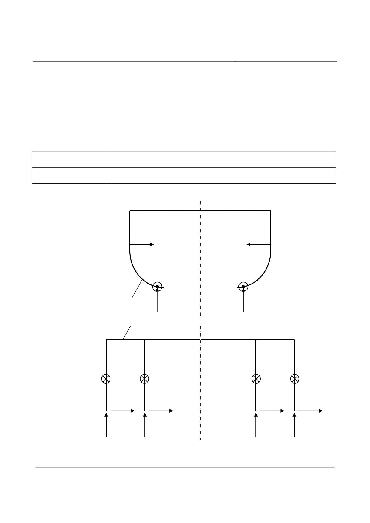
Rapid Maglev System
Maglev Technical
Committee
Design Principles
Vehicle
•
Articulation forces
•
The directions of the forces which are passed via the linkages of the support and guidance
magnets to the frame structure, as outlined in Figure 64, are applicable.
•
The terms used for the forces are explained in Table 3.
•
•
FxTM, FzTM
•
Articulation forces of the support magnets
•
FyFM
•
Articulation forces of the guidance magnets
Table 3: Terms used for the articulation forces
FyFM
FyFM
FxTM
FxTM
FzTM
FzTM
Structure
Suspension frame
FyFM
FyFM
FyFM
FyFM
FxTM
FxTM
FxTM
FxTM
FzTM
FzTM
FzTM
FzTM
•
•
Figure 64: Articulation forces on the frame structure
Title
High-speed Maglev System Design Principles
Vehicle, Part II, Dimensioning
Doc.No.:
67694
Version White
Issue date
15.02.2007
Page 11
paper
Rapid Maglev System
Maglev Technical
Committee
Design Principles
Vehicle
•
•
General
A-loads
Loads from operation in failure-free state for demonstration of fati-
gue strength
S-loads
Maximum possible loads during operation in failure-free state
and/or subject to exceptional actions for demonstration of load-
bearing capacity
Vehicle weights for passenger transport
•
The weight of the maglev vehicles and the payloads to be taken into account shall be laid
down specific to each project.
•
Vehicle sections for passenger transport include luggage compartments (e.g. for passen-
gers’ luggage).
Vehicle deadweight
•
Definition of the vehicle deadweight, see MSB AG-ABK&DEF Annex 1: Weight of the vehi-
cle incl. equipment (e.g. seating) without payload.
•
The overall masses of the operating staff and working stocks are included - where present.
Payload for passenger vehicles
•
Typical passenger weights
• Long-distance traffic
80 kg per passenger with luggage
• Regional traffic
70 kg per passenger
• Airport link
90 kg per passenger with luggage
•
Typical passenger densities in standing room areas
• Long-distance traffic
no standing room
• Regional traffic
320 kg/m²
• Airport link
1 person / m² (80 % of journeys)
2 people / m² (15 % of journeys)
320 kg/m² (5 % of journeys)
•
Typical weight per unit area in luggage area:
Title
High-speed Maglev System Design Principles
Vehicle, Part II, Dimensioning
Doc.No.:
67694
Version White
Issue date
15.02.2007
Page 12
paper
Rapid Maglev System
Maglev Technical
Committee
Design Principles
Vehicle
•
300 kg/m²
•
The weights to be assessed must be confirmed specific for each project or be laid down
differently.
Vehicle weight with payload
•
Weight of the fully equipped vehicle with payload
•
Average vehicle weight:
80% payload
•
Permissible vehicle weight:
100% payload
•
The payload for vehicle sections for passenger transport depends on the number of pas-
senger seats and, in standing room areas, on the number of passengers per m². These values are
set by the operator taking into account the legal provisions regarding this matter and give the mass
of the load and/or passengers which may be carried on the maglev train.
Maximum vehicle weight
•
Weight of the fully equipped vehicle subject to exceptional action.
•
The maximum vehicle weight of a section occurs in exceptional operating situations
(evacuation into neighbouring sections).
•
Typical value for standing room area: see Chapter 0
Vehicle weights for goods transport
•
The payload for goods sections shall be laid down on a project-specific basis and gives the
weight of the load which may be carried on the maglev train.
Title
High-speed Maglev System Design Principles
Vehicle, Part II, Dimensioning
Doc.No.:
67694
Version White
Issue date
15.02.2007
Page 13
paper
Rapid Maglev System
Maglev Technical
Committee
Design Principles
Vehicle
Design release
•
For the release of the design, a release programme must be implemented by the manufac-
turer of the vehicle.
•
The aim of the release programme is to demonstrate that the design of the carriage body
and of the magnetic running gear complies with the conditions laid down in the technical specifica-
tion.
•
The release programme must show that the behaviour of the vehicle assemblies manufac-
tured according to design targets permits appropriate operation without the occurrence of failure or
breakdown, permanent deformation or fatigue cracks. In addition, it must be demonstrated that
further components or sub-assemblies are not adversely affected.
•
The release programme must contain detailed information concerning how release of the
design should proceed and must indicate the necessary parameters for application of the various
parts of the procedure. These parameters must be laid down in three stages:
• the release procedure (e.g. combination of load cases for calculations and static tests, pro-
grammes for fatigue tests, tracks for track tests);
• the values of the different load cases;
• the release criteria (processing of the measured or calculated values, loading limits, criteria for
implementing fatigue tests).
•
The details regarding the release programme are listed in the following section 0.
•
Title
High-speed Maglev System Design Principles
Vehicle, Part II, Dimensioning
Doc.No.:
67694
Version White
Issue date
15.02.2007
Page 14
paper
Rapid Maglev System
Maglev Technical
Committee
Design Principles
Vehicle
Structural requirements
General
•
The maglev vehicles of the maglev system must withstand the maximum loads in accor-
dance with the operating requirements and must achieve the required service life under normal
operating conditions with appropriate probability of survival.
•
The capacity of the maglev vehicle to resist permanent deformations and breakdown must
be demonstrated by means of calculation and/or testing.
•
The vehicle strength shall be assessed according to the following criteria:
• Assessment of the exceptional loads, i.e. the maximum stresses which must be withstood
while maintaining full operating capacity (S-loads).
• Observation of sufficient safety so that uncertainties are covered in the demonstration, and no
risks occur for passengers or third parties if the specified loads are exceeded.
• Demonstration of sufficient rigidity so that the deformations under specified loads and the
characteristic frequencies of the structures conform to the limits determined by the operating
requirements.
• Tolerability of operating or cyclical loads so that structural strength is not impaired during the
stated service life (A-loads).
•
The above requirements shall be demonstrated by means of calculations in accordance
with Chapter 0 by demonstrating the load-bearing capacity or in accordance with Chapter 0 by
demonstrating the fatigue strength.
•
The operator must provide all data which determine the expected operating conditions,
(“project-specific statement”). In cooperation with the operator, it is the task of the manufacturer to
deduce all major load cases from these data so that they can be used as evidence and to ensure
that the design complies with them.
•
Where designs of existing vehicles for which safety has already been demonstrated are
developed further, earlier data may be used for a comparative demonstration if operating condi-
tions are the same. Changes in assemblies must generally be indicated. If changes which are rele-
vant for dimensioning are proposed, after agreement with the licensing authorities, the components
must be recalculated, if necessary, and/or be checked by means of a test. When using construc-
tion materials, the vehicle manufacturer or its sub-contractor must ensure that they have appropri-
ate data regarding compliance with the materials requirements. These data (standards etc) must
conform to the current state of the art.
Title
High-speed Maglev System Design Principles
Vehicle, Part II, Dimensioning
Doc.No.:
67694
Version White
Issue date
15.02.2007
Page 15
paper
Rapid Maglev System
Maglev Technical
Committee
Design Principles
Vehicle
Parameters influencing maglev vehicles
Design loads
•
All design loads which are used as a basis for the vehicle design must include all necessary
tolerances for uncertainties in their values. The design loads laid down in Chapter 0 include these
tolerances.
Materials
General
•
The minimum values of the material properties in accordance with the specifications for the
materials used must be used for the design of the vehicle structure. If the material properties are
affected by, for example,
• stress speed,
• time (e.g. ageing),
• environment (absorption of humidity, temperature etc.),
• welding or other manufacturing processes,
•
suitable minimum material characteristics must be used.
•
Permitted material characteristics
Static strength
•
The underlying static material characteristics, where available, must comply with the mini-
mum yield and/or proof stresses and the tensile strength of the materials data. The values used
should be taken from the corresponding European or national standards. If such standards are not
available, the most appropriate alternative data sources must be used on a project-specific basis.
Fatigue strength
•
The strength behaviour of the materials under oscillating loading must be taken from the
current European or national standards. If such standards are not available, the most appropriate
alternative data sources must be used. At the same time, reference may also be made to alterna-
tive data sources of equivalent status on a project-specific basis. The manufacturer must identify
substantiated materials data. Such materials data may be established by means of suitable tests
with regard to the use.
Title
High-speed Maglev System Design Principles
Vehicle, Part II, Dimensioning
Doc.No.:
67694
Version White
Issue date
15.02.2007
Page 16
paper