Design Principles High-speed Maglev System. Information (MSB, 2007) - page 4

High-speed Maglev System
Maglev Technical
Committee
Design Principles
Complete System
Parameter
Value
Unit
Peak current value main lightning current path
100
kA
Peak current value partial lightning current path
5
kA
Current profile
as first lightning discharge impulse,
-
see Figure 34
Table 52: Currents in the lightning and partial lightning current paths
Fields and induced voltages
Parameter
EMC / Lightning Protection Zones
Unit
0A
0B
1
2
dH/dt
1.6.1011
1.6.1011
1.6.1010
1.6.109
A/ms
H
1.6.105
1.6.105
1.0.105
6.3.104
A/m
dE/dt
5.0.1011
<5.0.1011
<5.0.1010
<5.0.109
V/ms
E
5.0.105
<5.0.105
<5.0.104
<5.0.103
V/m
Table 53: Fields and field changes; distance from lightning current path: 0.1 m
Parameter
EMC / Lightning Protection Zones
Unit
0A
0B
1
2
dH/dt
1.6.1010
1.6.1010
1.6.109
1.6.108
A/ms
H
1.6.104
1.6.104
1.0.104
6.3.103
A/m
dE/dt
5.0.1011
<5.0.1011
<5.0.1010
<5.0.109
V/ms
E
5.0.105
<5.0.105
<5.0.104
<5.0.103
V/m
Table 54: Fields and field changes; distance from lightning current path: 1 m
Parameter
EMC / Lightning Protection Zones
Unit
0A
0B
1
2
Uind in 10x10 cm measurement loop with one turn
2 000
2 000
200
20
V
Uind in 2-core cable,
20 000
20 000
2 000
200
V
core spacing: 1 cm, length: 1 m
Table 55: Induced voltages by magnetic field in lightning strike; distance from lightning current path: 0.1 m
Title
High-speed Maglev System Design Principles
Complete System Annex 3 Environmental Conditions
Doc.No.:
67285
Version White pa-
Issue date
15.02.2007
Page 30
per

High-speed Maglev System
Maglev Technical
Committee
Design Principles
Complete System
Parameter
EMC / Lightning Protection Zones
Unit
0A
0B
1
2
Uind in 10x10 cm measurement loop with one turn
200
2 00
20
2
V
Uind in zweiadriges Kabel,
2 000
2 000
200
20
V
core spacing: 1 cm, length: 1 m
Table 56: Induced voltages by magnetic field in lightning strike; distance from lightning current path: 1 m
Radiated Interference
The immunity of the MSB vehicle to radiated interference must meet the requirements of
/DIN EN 50121/ Part 3-1. The requirements of /DIN EN 50121/ Part 3-2 must be satisfied for
the immunity of devices and equipment installed in the vehicle.
The above requirements must be permanently guaranteed by design engineering measures.
Limits of immunity for high frequency fields
Parameter
EMC / Lightning Protection Zones
Field strength in [V/m]
0A
0B
1
2
Frequency range 0.15 MHz - 1 GHz
20
20
< 12
< 1.2
Frequency range 1-4 GHz
•
Vehicle interior (FI1-FI3)
20
< 20
< 20
- at 0.2 m min. distance from mobile radio devices -
•
Underfloor area (FA1-FA3)
20
20
< 20
< 20
- at 0.4 m min. distance from mobile radio devices -
Frequency range 37-39.5 GHz
-
Vehicle interior (FI1-FI3)
2.1
< 2.1
< 2.1
-
Underfloor area (FA1-FA3)
0.21
0.21
< 0.21
< 0.21
- Field strength is greatly reduced compared with primary environ-
ment as the lightning protection zones are not in the radio beam
range -
Table 57: Electromagnetic interference field strengths in the EMC / lightning protection zones
Title
High-speed Maglev System Design Principles
Complete System Annex 3 Environmental Conditions
Doc.No.:
67285
Version White pa-
Issue date
15.02.2007
Page 31
per

High-speed Maglev System
Maglev Technical
Committee
Design Principles
Complete System
Limits of immunity for magnetic fields
Parameter
EMC / Lightning Protection Zones
Continuous magnetic field strength in [A/m]
0A
0B
1
2
16 2/3 Hz
100
100
100
100
50 Hz
100
100
100
100
Table 58: Magnetic interference field strengths in the EMC / lightning protection zones
It must be assumed that the fields in Zone 0B are attenuated by the car body compared with
Zone 0A. However the car body attenuation is not separately measured so it is conservatively
taken to be 0 dB, i.e. without attenuation.
The levels for Zone 0B contain possible room resonances in the vehicle interior and the fields
of mobile radio devices.
The shield attenuation in Zones 1 and 2 is maintained by design reserves and/or by mainte-
nance.
Secondary environment in installations
The proper operation of the following installations muss must be guaranteed within the sec-
ondary environmental conditions specified in the sections below.
Secondary environment on the long stator
The following environmental conditions that are given for the long-stator winding also apply
by analogy to other items of equipment and mount-on parts of the guideway beams.
It must be remembered that the secondary environmental conditions depend on the design of
the guideway beams and substructures.
The following values must be verified and defined project-specifically.
Temperature
Parameter
Value
Unit
Max. temperature rise of the long-stator space envelope compared with the primary environ-
5
K
ment
Table 59: Temperature
Title
High-speed Maglev System Design Principles
Complete System Annex 3 Environmental Conditions
Doc.No.:
67285
Version White pa-
Issue date
15.02.2007
Page 32
per
High-speed Maglev System
Maglev Technical
Committee
Design Principles
Complete System
Mechanical load on the long-stator winding
The following effects from the guideway beam taken into consideration when determining the
mechanical load:
•
Effects from the static and dynamic deformation of the beam due to operations and
to the beam's natural oscillations that can be caused especially by slow moving
MSB vehicles.
•
Effects from deformation of the beam due to temperature changes
- Linear expansion
- Deformation due to non-uniform temperature distribution
•
Deformation of the substructures due to operation (driving/braking)
The natural oscillation behaviour of the various items of equipment and mount-on parts must
also be allowed for when determining the mechanical load.
Parameter
Value
Unit
Effect on the long-stator winding from guideway beam vibration
Max. frequency
35
Hz
Acceleration in x-direction (RMS)
20
m/s²
Acceleration in y-direction (RMS)
50
m/s²
Acceleration in z-direction (RMS)
50
m/s²
Tägliche Dauer der Einwirkung (akkumuliert)
5
min
Table 60: Typical vibration effects on a the long stator
Parameter
Value
Unit
Mechanical movement at the beam joints
Limits of deviation from nom. dimension
-32 to +63
mm
Table 61: Deviation from nominal dimension at beam joints
Parameter
Value
Unit
Movement cycle at the beam joints due to temperature response curve
Maximum daily beam expansion gap change in x-direction
30
mm
Mean daily beam expansion gap change in x-direction
12
mm
Mean annual beam expansion gap change in x-direction
12
mm
Table 62: Thermal effect at the beam joints
Title
High-speed Maglev System Design Principles
Complete System Annex 3 Environmental Conditions
Doc.No.:
67285
Version White pa-
Issue date
15.02.2007
Page 33
per
High-speed Maglev System
Maglev Technical
Committee
Design Principles
Complete System
Parameter
Value
Unit
Movement cycle due to effects from operation
Max. number of cycles
200
1/day
Min. cycle time resulting from min. train length
1
s
Max. change in beam expansion gap in x-direction (at max. speed)
3.5
mm
Mean change in beam expansion gap in x-direction (at max. speed)
2
mm
Table 63: Effect of vehicle acceleration and retardation and resulting change in beam expansion gap
Pollution Degree
The requirements of /DIN EN 60664-1/ for pollution degree 4 must be satisfied.
EMC / Lightning protection
The requirements defined in / DIN EN 62305-4/ for LPZ 0B must be satisfied.
Secondary environment inside buildings (e.g. substations,
switching points, point switching boxes)
The values for airconditioned service/machine rooms must be defined project-specifically.
Climate
Must be defined project-specifically.
Pollution Degree
The requirements of /DIN EN 60664-1/ for pollution degree 2 must be satisfied.
EMC / Lightning protection
The requirements defined in / DIN EN 62305-4/ for LPZ 0B must be satisfied as a minimum.
Any necessary defining of areas with Zones LPZ 1 or LPZ 2 must be done as part of the EMC
building design.
Title
High-speed Maglev System Design Principles
Complete System Annex 3 Environmental Conditions
Doc.No.:
67285
Version White pa-
Issue date
15.02.2007
Page 34
per
High-speed Maglev System
Maglev Technical
Committee
Design Principles
Complete System
Environmental conditions with covered guideway sections
The following differences compared with guideway sections directly exposed to the actions of
the primary environment must be considered for guideway sections that are covered over:
Characteristic
Differences
Temperature
The max. limits of the primary environment are not achieved.
Humidity
Higher than the average for the primary environment
Wind
max. 10 min. mean: 10 m/s
Ice/snow
No snow or ice cover of the guideway's functional surfaces
Effective length of the cover in relation to wind and
The length of the covered structure less 10 m for each transitional
ice/snow
section is used as a guide value. The actual length must be defined
project-specifically.
Table 64: Environmental conditions in covered guideway sections
Environmental conditions in tunnel sections
In a tunnel, the environmental conditions of temperature, humidity, air movement / wind must
be considered depending on the particular locality and as a function of parameters such as
the number of tracks, tunnel structure, train sequence etc.
The environmental conditions for a particular tunnel will therefore have to be defined project-
specifically.
The data given the following sections, based on Annex A of
/DIN EN 50125-2/, must therefore be regarded as guide values.
Temperature
For tunnels less than 2000 m long and in the first and last 1000 m section of tunnels longer
than 2000 m, the same temperature assumptions should be made as for open air.
The lowest temperature in the central section of long tunnels (> 2000 m) can be assumed to be
20 K higher than in open air and the highest temperature can be reduced by 5 K.
Humidity
Humidity tends to be low where the tunnel walls can prevent a significant amount of humidity
from penetrating.
Structural measures against humidity penetration must be defined project-specifically.
The max. absolute humidity in the tunnel must be assumed according to /DIN EN 50125-3/,
Table 3 as 30 g/m3.
Wind
A figure of 3 m/s can be assumed for the 10 min. mean wind speed.
Title
High-speed Maglev System Design Principles
Complete System Annex 3 Environmental Conditions
Doc.No.:
67285
Version White pa-
Issue date
15.02.2007
Page 35
per
High-speed Maglev System
Maglev Technical Committee
Design Principles
Rules for Operation
High-speed Maglev System
Design Principles
Complete System
Annex 4 Rules for Operation
(Train Operation and Maintenance)
The author reserves the copyright in this document and all attachments.
All rights reserved
Title
High-speed Maglev System Design Principles
Complete System Annex 4, Rules for Operation
Doc. no.:
69061
Version
White paper Issue date
15.02.2007
Page 1
High-speed Maglev System
Maglev Technical Committee
Design Principles
Rules for Operation
Distribution
This documents has been approved for publication by the Technical Committee Rules for Op-
eration (Train Operation and Maintenance).
Title
High-speed Maglev System Design Principles
Complete System Annex 4, Rules for Operation
Doc. no.:
69061
Version
White paper Issue date
15.02.2007
Page 2
High-speed Maglev System
Maglev Technical Committee
Design Principles
Rules for Operation
Change history
Release date: 15.02.2007, white paper, Technical Committee Rules for Operation
Title
High-speed Maglev System Design Principles
Complete System Annex 4, Rules for Operation
Doc. no.:
69061
Version
White paper Issue date
15.02.2007
Page 3
High-speed Maglev System
Maglev Technical Committee
Design Principles
Rules for Operation
List of contents
1 Distribution
2
2 Change history
3
3 List of contents
4
4 General
6
4.1
Purpose of the document, scope
6
4.2
High-speed Maglev System Design Principles
6
4.3
Abbreviations and definitions
7
4.4
Statutes, regulations, standards and directives
7
4.5
Indentification and binding value of requirements
7
5 Preparation of the body of rules for operation
8
6 Structure, breakdown and scope of the body of rules for operation
9
6.1
Structure and breakdown of the body of rules
9
6.2
Parts of the body of rules
9
7 Management types and systems
11
7.1
Safety Management System (SMS)
11
7.2
Quality Management (QM)
11
7.3
Occupational Safety Management
11
7.4
Environmental Protection Management
11
8 Need for regulation - Train operations and maintenance
12
8.1
High-level requirements
12
8.1.1
Monitoring of Limits
12
8.1.2
Requirements for the train operations and maintenance personnel
12
8.1.3
Communication requirements
12
8.2
Need for regulation - Train operations
12
8.2.1
Rules for train operations
12
8.2.2
"Normal operation" mode
13
8.2.3
"Departure from normal operation" mode
14
8.2.4
Train operations with special vehicles
15
8.2.5
Need for regulation for special measures
15
8.2.5.1
Security
15
8.2.5.2
Winter service
16
8.2.5.3
Vegetation control
16
8.3
Need for regulation - Maintenance
17
Title
High-speed Maglev System Design Principles
Complete System Annex 4, Rules for Operation
Doc. no.:
69061
Version
White paper Issue date
15.02.2007
Page 4
High-speed Maglev System
Maglev Technical Committee
Design Principles
Rules for Operation
8.3.1
Rules for Maintenance
17
8.3.1.1
Contents of the rules for maintenance
17
8.3.1.2
Maintenance programme
17
8.3.1.3
Maintenance instructions
18
8.3.1.4
Rules for the performance of maintenance measures
18
8.3.1.5
Rules for the sequence / oganisation of maintenance measures
18
8.3.2
Maintenance management
19
8.3.3
Maintenance measures
19
8.3.3.1
Principles for the performance of maintenance measures
19
8.3.3.2
Planning of maintenance measures
20
8.3.3.3
Ordering of maintenance measures
20
8.3.3.4
Performance of maintenance measures
20
8.3.3.5
Completion of maintenance measures
20
8.3.3.6
Confirmation/documentation of maintenance measures
20
8.4
Need for regulation - Interface between train operations and maintenance
21
8.4.1
Principles of interfacing between train operations and maintenance
21
8.4.2
Clearance procedure
22
8.4.3
Hand-over and acceptance procedure
23
8.4.4
Trains operations support by Maintenance
23
Title
High-speed Maglev System Design Principles
Complete System Annex 4, Rules for Operation
Doc. no.:
69061
Version
White paper Issue date
15.02.2007
Page 5
High-speed Maglev System
Maglev Technical Committee
Design Principles
Rules for Operation
General
Purpose of the document, scope
This design principles applies to a high-speed maglev system according to the General
Maglev System Act /AMbG/.
Sections 24 and 8 /MbBO/ require the MSB entrepreneur to establish rules for operation.
This document contains the non project-specific requirements for rules for the operation of
MSB systems, consisting of train operation and maintenance.
This Design Principles applies in conjunction with the High-speed Maglev System Design
Principles Complete System /MSB AG-GESAMTSYS/ and its Annexes.
This Design Principles governs the operation of MSB systems.
Separate rules must be established for operation during the construction and commissioning of
MSB systems.
The following statements relate to the MSB entrepreneur's rules for operation (train operation
and maintenance), referred to hereafter as the "body of rules", for the use of MSB systems to
carry passengers.
The carriage of goods must be considered separately.
The requirements are addressed to MSB entrepreneurs (as per Section 5 /AMbG/).
The requirements are also addressed to the manufacturers of the MSB system and its compo-
nents in so far as they make statements about required documentation and impose conditions
on the organisation and procedures for the operation of the MSB system that must be taken
into consideration in the design of all subject areas of the MSB system.
Where the MSB entrepreneur's or manufacturer's internal rules differ from the requirements of
this Design Principles, those internal rules may be retained subject to evidence of equivalent
safety or, in the case of definitions and vocabulary, subject to proof of analogous meaning.
High-speed Maglev System Design Principles
This document forms part of documentation for high-speed maglev systems consisting
of a series of Design Principles. The document tree is shown in Figure 1 /MSB AG-
GESAMTSYS/.
The high-level "complete system" design principles and its annexes apply uniformly for the
whole documentation:
•
High-speed Maglev System Design Principles Complete System, Doc. No.: 50630,
/MSB AG-GESAMTSYS/
•
Annex 1: High-speed Maglev System Abbreviations and Definitions, Doc. No.:
67536, /MSB AG-ABK&DEF/
•
Annex 2: High-speed Maglev System Statutes, Regulations, Standards and Direc-
tives, Doc. No.: 67539, /MSB AG-NORM&RILI/
Title
High-speed Maglev System Design Principles
Complete System Annex 4, Rules for Operation
Doc. no.:
69061
Version
White paper Issue date
15.02.2007
Page 6
High-speed Maglev System
Maglev Technical Committee
Design Principles
Rules for Operation
•
Annex 3: High-speed Maglev System Environmental Conditions, Doc. No.: 67285,
/MSB AG-UMWELT/
•
Annex 5: High-speed Maglev System Noise, Doc. No.: 72963, /MSB AG-
SCHALL/
Abbreviations and definitions
The abbreviations and definitions given in /MSB AG-ABK&DEF/ apply.
Instead of the term "train operation" as used in this document, the term "operation" is also in
commonly used among operators of track-guided transport systems and may therefore be used
in the body of rules of the MSB entrepreneur instead of the term "train operation". This also
applies to corresponding word combinations.
Statutes, regulations, standards and guide-
lines
The normative documents listed in /MSB AG-NORM&RILI/ contain requirements that form
part of the High-speed Maglev System Design Principles by cross reference in the High-speed
Maglev System Design Principles.
Where normative documents in /MSB AG-NORM&RILI/ are dated, subsequent changes or
revisions of these publications do not apply.
With undated references, the latest version of the normative document that is referred to ap-
plies.
The version of the standards and guidelines to be observed in an MSB project must be decided
bindingly on a project-specific basis.
A list of statutes, ordinances, standards and directives for the MSB entrepreneur's body of
rules will be found in the document Maglev High-speed System Design Principles Complete
System, Annex 2: Statutes, Regulations, Standards and Directives /MSB AG-NORM&RILI/.
Identification and binding value of require-
ments
The requirements of /DIN 820/, Part 2, were essentially applied in the preparation of this
document.
In the following chapters and the annexes of this document
•
Requirements are shown in normal font
•
Explanations, guide values and examples are shown in italics
Title
High-speed Maglev System Design Principles
Complete System Annex 4, Rules for Operation
Doc. no.:
69061
Version
White paper Issue date
15.02.2007
Page 7
High-speed Maglev System
Maglev Technical Committee
Design Principles
Rules for Operation
Preparation of the body of rules for operation
The entirety of the rules must be:
•
complete,
•
consistent,
•
free from contradiction
within themselves.
The rules must conform to the MSB entrepreneur's requirements relating to safety manage-
ment, especially according to /DIN EN 61508/, /DIN EN 50126/ and /DIN EN 50129/ (see
Chapter 0).
Requirements in the body of rules must be checked for consistency with the project-specific
safety, operation and maintenance concept.
The terms and abbreviations used in the body of rules must be clearly defined. The defined
terms and abbreviations must be used consistently.
The structure of the body of rules must be user-friendly.
A body of rules is user-friendly in particular when
•
it directly addresses the individual target groups,
•
its contents are presented in a clear, understandable and descriptive manner, and
•
the auxiliary verbs in it are used according to DIN 820-2/ Annex G.
The body of rules must be practicable.
A body of rules is practicable when
•
the rules it contains optimally support the specified functionality of the deployed
technology, and
•
all users can apply the rules well and without particular difficulty in operation.
The body of rules should be modular in structure.
It is modular in structure when it consists of individual self-contained modules which are
mutually compatible.
Title
High-speed Maglev System Design Principles
Complete System Annex 4, Rules for Operation
Doc. no.:
69061
Version
White paper Issue date
15.02.2007
Page 8
High-speed Maglev System
Maglev Technical Committee
Design Principles
Rules for Operation
Structure, breakdown and scope of the body of rules for operation
Structure and breakdown of the body of
rules
The body of rules must present the structure and breakdown of the rules in a suitable form,
e.g. as a table of contents.
Additional provisions can be published as annexes or supplements. The body of rules may
contain printed forms to aid working.
If the MSB entrepreneur stipulates uniform principles for the drafting, structure, presentation
and documentation of rules, then these principles should be applied to the entire body of rules.
Parts of the body of rules
The basic understanding of the MBS system that is necessary for the work by the personnel
must be conveyed to the personnel.
The description and presentation must include the installations that are relevant for operation.
The installations should be presented in clear form in a location plan.
The MSB vehicles and special vehicles used in the project as well as any trailers and work
scaffolding must be described.
The body of rules for the operation of the MSB system consists of:
•
rules for train operations,
•
rules for maintenance,
•
general organisational rules for operation (train operations and maintenance).
General organisational rules must at least describe the division and distribution of responsi-
bilities within the MSB entrepreneur's organisation.
General organisational rules can exist either as a separate document or can be incorporated
into the rules for train operations or rules for maintenance.
The general organisational rules must be formulated so that it is clear how the defined safety
objectives are to be achieved under the given project-specific system preconditions and within
the project-specific operational framework.
The rules must clearly set out the principle for the division of responsibility for safety related
and non safety related (e.g. commercial) factors of operation in the organisation as well as in
the work and management processes, systems and types.
Other applicable documents must be defined in the body of rules. They are subject to the same
quality criteria as the body of rules itself.
Examples of other applicable documents:
•
Operating instructions of the MSB system manufacturers,
•
Maintenance instructions of the MSB system manufacturers.
Basic documents used to prepare the body of rules do not form part of it.
Examples of basic documents:
•
the safety related instructions for use (SAV) of the MSB system manufacturers,
Title
High-speed Maglev System Design Principles
Complete System Annex 4, Rules for Operation
Doc. no.:
69061
Version
White paper Issue date
15.02.2007
Page 9
High-speed Maglev System
Maglev Technical Committee
Design Principles
Rules for Operation
•
the instructions according to /Directive 98/37/EC/,
•
conditions and secondary provisions in official decisions / permits,
•
documents necessitated by requirements in relevant legislation, regulations, stan-
dards and directives (e.g. manuals for Safety Management / Quality Management).
Title
High-speed Maglev System Design Principles
Complete System Annex 4, Rules for Operation
Doc. no.:
69061
Version
White paper Issue date
15.02.2007
Page 10
High-speed Maglev System
Maglev Technical Committee
Design Principles
Rules for Operation
Management types and systems
Safety Management System (SMS)
The MSB entrepreneur must put in place a safety management system based on /Directive
2004/49/EC/.
The SMS is the organisation established by an MSB entrepreneur and the precautions he
takes to guarantee the safe execution of his operational procedures.
The SMS must guarantee that the rules for organisation, train operations and maintenance
which arise out of the project-specific safety concept are incorporated into the body of rules.
Quality Management (QM)
The measures and rules for quality management must be presented in the body of rules and
conform to the applicable regional, national and international regulations, standards (e.g.
/standards series EN ISO 9000 ff./) and the MSB entrepreneur's QM Manual.
Rules for quality assurance, quality planning and the quality procedures must be contained in
the body of rules if they relate to the safety of the operation of the MSB system.
Occupational Safety Management
The measures and arrangements put in place for occupational safety must be set out in the
body of rules and must satisfy the applicable regional, national and international rules, stan-
dards, regulations and national legislation.
Personnel protection must be assured by appropriate arrangements.
The national legislation includes a collection of statutes and ordinances on this subject that
are contained in /MSB AG-NORM&RILI/ /PERSSCH/.
The occupational safety arrangements may be summarised in a suitable manner, e.g. in the
form of an occupational safety management system.
Environmental Protection Management
The measures and arrangements put in place for environmental protection must be set out in
the body of rules and must satisfy the applicable regional, national and international rules,
standards, regulations and national legislation. The current environmental findings must be
taken into consideration.
The national legislation includes a collection of statutes and ordinances on this subject that
are contained in /MSB AG-NORM&RILI/ /PERSSCH/.
The reviews of work processes and work contents and their impact on the environment and
the measures for reviewing compliance with environmental protection measures must be de-
fined in the body of rules.
The environmental protection arrangements may be summarised in a suitable manner, e.g. in
the form of an environmental protection management system.
Title
High-speed Maglev System Design Principles
Complete System Annex 4, Rules for Operation
Doc. no.:
69061
Version
White paper Issue date
15.02.2007
Page 11
High-speed Maglev System
Maglev Technical Committee
Design Principles
Rules for Operation
Need for regulation - Train operations and maintenance
High-level Requirements
Monitoring of Limits
The MSB entrepreneur must monitor compliance with the limits and other specified values
defined in the Design Principles Complete System and Subsystems.
The corresponding rules, recording and analysis procedures, assessment criteria and the
measures to be taken in case of noncompliance must be defined project-specifically in the
body of rules.
The body of rules must define how the effects of special load cases are registered their reli-
ability assured in accordance with the MSB Design Principles Complete System /MSB AG-
GESAMTSYS/.
Requirements for the train operation and maintenance per-
sonnel
The body of rules must describe for each workplace the requirements which the MSB entre-
preneur makes regarding personnel suitability, fitness and qualification.
The body of rules must stipulate that every activity in train operations and maintenance may
only be carried out by suitable, fit and qualified personnel.
The procedures used to determine the suitability and fitness of personnel, the regular review
and requirements governing review intervals, periods and documentation must be laid down
in the body of rules.
Personnel training/qualification must be anchored in the body of rules at least to the extent
that it is clearly stated which duties, competences and responsibilities of the personnel are
associated with which minimum qualification.
It must be clearly stated how the qualification is obtained, if necessary how it is regularly re-
peated and/or received, and how all qualifications of the personnel are organised, documented
and administered.
Communication requirements
Rules for safety related communication including technical and organisational requirements
must be defined.
Technical communications equipment, its fallback policies in the event of fault or failure, and
its integration into operational procedures must be described.
The rules for recording and storing communications must be defined.
Need for regulation - Train operations
Rules for train operations
The rules for train operations must be defined in the Operation Manual according to Section
24 /MbBO/ and must cover at least the entire train operations.
Title
High-speed Maglev System Design Principles
Complete System Annex 4, Rules for Operation
Doc. no.:
69061
Version
White paper Issue date
15.02.2007
Page 12
High-speed Maglev System
Maglev Technical Committee
Design Principles
Rules for Operation
The train operations must be carried out in one of the following two modes (see High-speed
Maglev System Design Principles Complete System /MSB AG-GESAMTSYS/, Chapter
6.3.1.2):
•
Normal operation
•
Departure from normal operation.
The option of executing both modes simultaneously must be provided so far as is technically
possible and desirable for operational reasons.
The body of rules must lay down the conditions under which maintenance operations may be
performed in the event of disruptions in train operations.
Responsibilities during this process must be described.
Arrangements must be put in place in the event of an nonscheduled stop by the MSB vehicle.
In the event of disruptions in train operations which involve evacuation of the MSB vehicle,
the body of rules must state how the evacuation must be initiated and carried out.
The safety related planning and dispatching processes for the train operations must be de-
scribed.
Planning and dispatching processes are safety related when they ensure that specified limits
for the MSB system are complied with or their realisation may affect the integrity of persons
and property.
"Normal operation" mode
The constraints for normal operation (see Annex 1: High-speed Maglev System Abbreviations
and Definitions /MSB AG-ABK&DEF/ ) must be laid down and described in the rules for
train operations.
In the body of rules, the MSB entrepreneur must define (see also Section 22 /MbBO/):
•
operational preconditions for the start and sequence of normal operation,
•
technical preconditions for the start and sequence of normal operation,
•
changes between manually and automatically generated journey inputs within
normal operation,
•
conditions for leaving the normal operation mode,
•
requirements and procedures for return to the normal operation mode,
•
procedures when journey preconditions are no longer met.
When individual processes require actions by the operating personnel in normal operation,
these actions must be described.
The actions and restrictions necessary to prevent or avert potential hazardous states in normal
operation must be described.
The measures that must be taken in the event of foreseeable technical and operational disrup-
tions in the operation flow must be described.
The measures that must be taken in the event of foreseeable hazardous incidents must be de-
scribed.
The monitoring activities, measures and intervention in the control and protection of train
operations to be carried out by operating personnel in response to technical or operational
requirements must be described.
Title
High-speed Maglev System Design Principles
Complete System Annex 4, Rules for Operation
Doc. no.:
69061
Version
White paper Issue date
15.02.2007
Page 13
High-speed Maglev System
Maglev Technical Committee
Design Principles
Rules for Operation
Where train operations are carried out simultaneously with construction and/or maintenance
operations, it must be decided
•
whether and how far construction and/or maintenance operations (e.g. subsystem
related, locally closed sections of line) may take place during normal operation,
and
•
how the areas in which construction and/or maintenance operations are being car-
ried out should be closed off and secured.
Responsibilities during this process must be defined.
"Departure from normal operation" mode
The functions that are not contained in the technical protection system must be defined in the
rules for train operation.
If necessary, appropriate safety measures (technical and/or organisational) must be described
in the body of rules.
The measures to be taken under personnel responsibility must be described in the body of
rules.
In the body of rules, the MSB entrepreneur must define (see also Section 22 /MbBO/):
•
operational preconditions for the start and sequence of the "departure from normal
operation" mode,
•
technical preconditions for the start and sequence of the "departure from normal
operation" mode,
•
changes between manually and automatically generated journey inputs within the
"departure from normal operation" mode,
•
conditions for leaving the "departure from normal operation" mode,
•
requirements and procedures for return to the "departure from normal operation"
mode,
•
procedures when journey preconditions are no longer met.
Provisions in the body of rules must ensure that the "departure from normal operation" mode
does not lead to an unsafe state of the MSB system.
The body of rules must define the conditions under which train operations are to be inter-
rupted due to the "departure from normal operation" mode.
Project-specific technical characteristics of the installations and of the MSB vehicles must be
taken into consideration when defining actions and measures taken under personnel responsi-
bility.
Automatic responses by the technical MSB equipment during the "departure from normal op-
eration" mode and the extent of the remaining technical protection must be described for the
train operation personnel.
This also applies to the monitoring activities, measures and intervention in the control and
protection of train operations to be carried out by operating personnel in response to technical
or non technical requirements.
Operations-monitoring measures for the systematic detection, identification/evaluation and
documentation of causes for the "departure from normal operation" mode must be defined in
the body of rules.
Title
High-speed Maglev System Design Principles
Complete System Annex 4, Rules for Operation
Doc. no.:
69061
Version
White paper Issue date
15.02.2007
Page 14
High-speed Maglev System
Maglev Technical Committee
Design Principles
Rules for Operation
The body of rules must define how the traffic movement director is to be informed of circum-
stances that may lead to the "departure from normal operation" mode.
The nature, format and scope of communication during the "departure from normal operation"
mode must be specified in the body of rules.
Actions for individual measures and operator interventions to ensure the required level of
safety under personnel responsibility, especially in an emergency situation, must be defined in
the body of rules in a suitable format (checklists, flow charts etc.).
Where train operations are carried out simultaneously with construction and/or maintenance
operations, it must be decided
•
whether and how far construction and/or maintenance operations (e.g. subsystem
related, locally closed sections of line) may take place during "departure from
normal operation" mode, and
•
how the areas in which construction and/or maintenance operations are being car-
ried out should be closed off and secured.
Responsibilities during this process must be defined.
Train operations with special vehicles
The body of rules must define types of special vehicles project-specifically.
Rules for moving special vehicles must be defined project-specifically.
Sequences, operator actions and communication as well as technical and non technical meas-
ures will depend on the technical equipment of the special vehicles.
The body of rules must indicate the conditions under which special vehicles may travel on the
MSB line (environmental conditions, MSB vehicles in service etc.).
Depending on the equipment of the special vehicles, measures against gauge profile violations
must be laid down.
Depending on the equipment of the special vehicles, measures for the avoidance of collisions
with
•
other special vehicles,
•
MSB vehicles,
•
installations,
•
persons and objects that project into the gauge profile
must be defined.
Parking and standby positions for special vehicles and the measures for immobilising the spe-
cial vehicles must be defined project-specifically.
Need for regulation for special measures
Security
The body of rules must describe the security system and security tasks in relation to the MSB
system. It must describe:
•
the principles and objectives of security,
•
the responsibility and acting persons for security,
Title
High-speed Maglev System Design Principles
Complete System Annex 4, Rules for Operation
Doc. no.:
69061
Version
White paper Issue date
15.02.2007
Page 15
High-speed Maglev System
Maglev Technical Committee
Design Principles
Rules for Operation
•
the tasks and scope of building security,
•
the tasks and scope of organisational security,
•
the documentation, verification and reporting of security.
It must be stipulated which security measures must be defined as a minimum. This relates to
all active and passive measures such as:
•
security of vehicles and installations from unauthorised access and unauthorised
intervention,
•
response to alarms and emergency calls,
•
Co-operation with authorities and organisations with security duties (BOS),
•
involvement of surveillance and security services.
Winter service
The rules for train operations must define the limits within which the safe operation of the
MSB system is also possible under winter weather conditions. The limits are specified in An-
nex 3: High-speed Maglev System Environmental conditions /MSB AG-UMWELT/.
The following limits are mentioned by way of example:
•
the permissible thickness of guideway icing (levitation / guidance areas),
•
the acceptable depth of snow on the guideway table and under the gradient.
The rules for train operations must state that the MSB system may only be operated within the
specified limits.
They must also indicate the responsibilities and measures for an approach to the limits being
detected in good time and being responded to with the necessary measures in accordance with
requirements.
General winter service measures around the traffic installations, the maintenance centre and
the transport routes that may also be performed by third parties must be project-specifically
regulated.
Vegetation control
Vegetation stocks long the MSB route must be monitored and cared for by regular inspec-
tions.
Measures must be defined for keeping the clearance gauge free. The following categories
must be taken into consideration:
•
Measures to protect against clearance gauge violation,
•
Measures for detecting a clearance gauge violation,
•
Measures for eliminating a clearance gauge violation.
The vegetation control measures must take into account that encroachment into the clearance
gauge due to natural growth is impossible and due to environmental influences (e.g. wind
break, snow loads on the vegetation) is largely prevented.
Title
High-speed Maglev System Design Principles
Complete System Annex 4, Rules for Operation
Doc. no.:
69061
Version
White paper Issue date
15.02.2007
Page 16
High-speed Maglev System
Maglev Technical Committee
Design Principles
Rules for Operation
Need for regulation - Maintenance
Rules for maintenance
Contents of the rules for maintenance
The principles of maintenance and the complete subdivision of maintenance into its basic ac-
tions are laid down in /DIN 31051/.
The basic terminology of maintenance and the classification of maintenance into different
types are defined in /DIN EN 13306/. /DIN EN 50126/ also applies.
These principles, subdivisions, terms and classifications must be used in the body of rules for
maintenance.
The maintenance of the MSB subsystems must be combined in an appropriate manner with
the maintenance of the MSB Complete System. The rules for maintenance must reflect this.
The rules for maintenance consist of:
•
maintenance programme,
•
maintenance instructions (for all of the maintenance measures listed in the mainte-
nance programme),
•
rules containing project-specific or location specific supplements (e.g. as work in-
structions and procedures).
Maintenance programme
A maintenance programme for the Complete System must be prepared on the basis of the
“Principles and procedures for creating the maintenance programme” (see /MbBO/ Section 8).
The maintenance programme must be prepared having particular regard to the following
points:
•
The maintenance programmes for the subsystems must contain all necessary main-
tenance measures for the particular subsystem.
•
The maintenance programmes for the subsystems must cover the Complete Sys-
tem.
•
The manufacturer of a particular item must list the possible faults and malfunctions
of that item and clearly assign them to a fault class.
•
The necessary responses and action by personnel must be defined for each fault
class. The action must at least take account of the impact of malfunctions and
faults on the safety of the system.
•
To identify the necessary maintenance measures, structural and/or functional
analyses of all MSB subsystems must be carried out, and the action defined, based
on accepted methods (e.g. FMEA /MSB AG-ABK&DEF/). The frequen-
cies/intervals of the maintenance measures must be defined on this basis.
•
A product structure plan is the basis for the structural and functional analysis.
•
A classification and/or prioritisation of maintenance measures in regard to their
safety relevance must be provided.
Title
High-speed Maglev System Design Principles
Complete System Annex 4, Rules for Operation
Doc. no.:
69061
Version
White paper Issue date
15.02.2007
Page 17
High-speed Maglev System
Maglev Technical Committee
Design Principles
Rules for Operation
The body of rules must clearly indicate the differentiation of responses to different classes /
priorities of maintenance measure.
Further requirements governing the creation of the maintenance programme - where they exist
- are contained in the respective Design Principles for the subsystems.
Maintenance instructions
Maintenance instructions must exist for all maintenance measures defined in the maintenance
programme.
The maintenance instructions must be prepared by the manufacturer of the particular technical
item under consideration (e.g. subsystem manufacturer).
They should be uniform in structure and presentation.
The maintenance instructions must contain all the information that is necessary to carry out
the maintenance measure.
Rules for the performance of maintenance measures
The maintenance rules must contain project and/or location specific information and instruc-
tions for the technical performance of the maintenance measures, e.g. in the form of work
instructions. These supplement the maintenance instructions.
The naming of the project and/or location specific information and instructions for the techni-
cal performance of maintenance measures shall be at the discretion of the entrepreneur.
The project and/or location specific information and instructions should contain at the least
the following particulars:
•
description of how the maintenance measures are carried out,
•
use of specific work aids/tools,
•
particulars about the use of the infrastructure,
•
specific information about occupational safety/environmental protection and the
use of personal protective equipment,
•
specific details about personnel qualification.
The project and/or location specific information and instructions, details and additions must
not unduly alter the contents of the maintenance instructions.
Rules for the sequence / organisation of maintenance measures
The maintenance rules must contain project and/or location specific information and instruc-
tions about the sequence and/or organisation of maintenance measures, e.g. in the form of
process instructions. These supplement the maintenance instructions.
The naming of the project and/or location specific information and instructions about the se-
quence and/or organisation of maintenance measures shall be at the discretion of the entre-
preneur.
The project and/or location specific information and instructions should contain at the least
the following particulars:
•
procedures for access to and presence in maintenance areas,
•
logging in/out, and safety procedures as well as warning procedures for mainte-
nance work,
Title
High-speed Maglev System Design Principles
Complete System Annex 4, Rules for Operation
Doc. no.:
69061
Version
White paper Issue date
15.02.2007
Page 18
High-speed Maglev System
Maglev Technical Committee
Design Principles
Rules for Operation
•
ordering maintenance work,
•
carrying out maintenance work,
•
completion and confirmation of maintenance work,
•
documenting maintenance work.
For fast moving and automatically operated vehicles, warning procedures are not suitable as
organisational measures for the protection of personnel inside the guideway danger area, and
must be excluded.
The project and/or location specific information and instructions, details and additions must
not unduly alter the contents of the maintenance instructions.
Maintenance management
The body of rules must present the complete maintenance process for the vehicles and instal-
lations, including maintenance management and the maintenance strategy.
All planning and scheduling processes for maintenance must be described.
The safety related planning and scheduling processes must be identified.
Planning and dispatching processes are safety related when they ensure that specified limits
for the MSB system are complied with or their realisation may affect the integrity of persons
and property.
Consideration must be given to the following requirements for maintenance management in
addition to the requirements of Chapter 0:
•
The body of rules for maintenance must be linked through the interface rules for
train operations and maintenance to the rules for train operations, and be consistent
with them.
•
Rules arising out of existing statutes, standards and directives (e.g. occupational
safety, environmental protection, fire safety, quality management etc.) must be an-
chored in the body of rules. This can be done by defining specific rules or by ref-
erences to the applicable documents.
Maintenance measures
Principles for the performance of maintenance measures
The "performance of maintenance measures" process sequence comprises the sub-processes
of planning, ordering, performing, completion and confirmation/documentation.
The sub-processes must be comprehensively described in the body of rules. The description
must provide at least the following particulars for all sub-processes:
•
contents of the sub-process,
•
sub-process sequence,
•
acting and responsible persons,
•
input variables of the sub-process,
•
output variables of the sub-process.
Title
High-speed Maglev System Design Principles
Complete System Annex 4, Rules for Operation
Doc. no.:
69061
Version
White paper Issue date
15.02.2007
Page 19
High-speed Maglev System
Maglev Technical Committee
Design Principles
Rules for Operation
The sub-process in which a maintenance measure is, and the person responsible for signing
off that maintenance measure, must be identifiable at all times. The technical and/or organisa-
tional arrangements that are necessary for this must be written down.
Planning of maintenance measures
Planning means the preparation of the future performance of maintenance measures. This
preparation relates to the resources of time, dates, personnel, material and infrastructure.
The planning must cover at least those measures identified in the maintenance programme as
safety related and measures covered by a statutory duty to produce supporting documentation.
Beside the requirements referred to in Chapter 0, the body of rules must also contain particu-
lars of the planning time and planning period and about how the planning is made known.
Ordering of maintenance measures
The principle of maintenance performance, "no work without an order", must be enshrined in
the body of rules.
The contents of the order and the format (printed paper forms, computer forms etc.) must be
defined.
The ordering of maintenance measures must be verifiable.
Performance of maintenance measures
The maintenance measures must be performed according to the manufacturer's technical in-
structions and the organisational rules of Maintenance.
Procedures for monitoring the maintenance measures must be defined.
The procedures and the acting and responsible persons for controlling the maintenance tasks
(e.g. in the event of plan/actual deviations) must be defined.
Rules must be laid down for executing vehicle movements for maintenance purposes. The
rules must relate to the items listed in Chapter 0.
Completion of maintenance measures
The completion of maintenance measures determined by reporting the technical completion of
the ordered measure.
Additional special rules must be made for safety related activities (e.g. the 'two pairs of eyes'
principle).
The contents of the completion report and the format (printed paper forms, computer forms
etc.) must be defined.
The completion report must be verifiable.
Confirmation/documentation of maintenance measures
The confirmation of a maintenance measure is determined by the detailed description of the
activity that has actually been carried out.
The data that are required for the confirmation of the completed measures must be defined.
The contents of the confirmation and the format (printed paper forms, computer forms etc.)
must be defined.
The confirmation must be verifiable.
Title
High-speed Maglev System Design Principles
Complete System Annex 4, Rules for Operation
Doc. no.:
69061
Version
White paper Issue date
15.02.2007
Page 20
High-speed Maglev System
Maglev Technical Committee
Design Principles
Rules for Operation
The lifecycle of replaced/repaired modules/smallest replaceable units must be clearly and
verifiably documented together with a fault description, the cause of the fault and the repair
carried out (if applicable, destruction of the faulty part and replacement by a new part).
Need for regulation Interface between train
operations and maintenance
Principles of interfacing between train operations and
maintenance
The operation of the MSB system is divided into train operations and maintenance.
There may be different areas of responsibility in the train operations and the maintenance of
the MSB system.
The individual areas of responsibility must be clearly described and separated from each other
in the body of rules.
In train operations and in maintenance, the areas of responsibility must be clearly allocated at
all times.
Train operations and maintenance can take place both simultaneously and consecutively.
Where train operations and maintenance take place simultaneously, the body of rules must
define criteria for the nature and scope of admissibility.
The framework conditions and prerequisites must be described and regulated.
Train operations and maintenance can take place simultaneously when reciprocal safety risks
do not arise.
If train operations and maintenance take place consecutively the body of rules must contain
arrangements for the transfer of responsibility.
In both instances, the body of rules must describe:
•
the organisation of the interfaces,
•
the technical systems involved in the interface,
•
the content and limits of the activities,
•
responsibility for initiating the measures,
•
the boundaries of responsibility for the complete system or subsystems,
•
the acting function owners,
•
the communication and information flows,
•
the necessary documentation,
•
the issuing of orders and suspension / clearance procedures,
•
the safety procedures,
•
the hand-over and acceptance procedures,
•
the performance of the maintenance measures.
The following communication rules in particular must be put in writing for train operations
and for the interface between train operations and maintenance:
Title
High-speed Maglev System Design Principles
Complete System Annex 4, Rules for Operation
Doc. no.:
69061
Version
White paper Issue date
15.02.2007
Page 21
High-speed Maglev System
Maglev Technical Committee
Design Principles
Rules for Operation
•
information about vehicle movements,
•
warning procedures,
•
written instructions,
•
information about temporary/local restrictions and special features,
•
rules governing how the persons responsible interact,
•
transmission of clearances and suspensions.
For fast moving and automatically operated vehicles, warning procedures are not suitable as
organisational measures for the protection of personnel inside the guideway danger area, and
must be excluded.
Clearance procedure
The body of rules must define responsibility for technical clearances of the system or - if in-
tended - of system components, both for the organisation and for the management and work
processes.
Technical and non technical journey preconditions must be met before train operations can
commence.
These journey preconditions must be described in the body of rules according to /MbBO/ Sec-
tion 22.
The various responsibilities for confirming compliance with the individual journey precondi-
tions must also be defined in the body of rules.
Compliance with the journey precondition must be confirmed according to an appropriate
clearance procedure.
The clearance procedure must also describe the associated verification processes.
Compliance with the technical journey preconditions must be established and confirmed by
the area of responsibility of Maintenance. This confirmation certifies that the technical re-
quirements (functional capability as per /DIN 31051/ and /DIN EN 13306/) for the use of the
system (subsystem, complete system) are fulfilled.
The non technical journey preconditions must be confirmed in the area of responsibility of
train operations.
If there is provision for clearing the parts of a subsystem, then the above mentioned descrip-
tions must relate accordingly to the level of those parts of the subsystems. The parts must be
defined.
The clearance procedures, clearance conditions and the withdrawal of clearances must be de-
scribed in the body of rules. The description must cover at least the following points:
•
the persons acting (person responsible, recipient etc.),
•
the content of the message (technical, operational, subsystem etc.),
•
an indication of the criteria against which checks are made,
•
the possible restrictions/constraints,
•
the format and/or manner (e.g. in writing, electronic),
•
the documentation.
Title
High-speed Maglev System Design Principles
Complete System Annex 4, Rules for Operation
Doc. no.:
69061
Version
White paper Issue date
15.02.2007
Page 22
High-speed Maglev System
Maglev Technical Committee
Design Principles
Rules for Operation
Hand-over and acceptance procedure
Responsibility for the handed over/accepted system/subsystem changes upon hand-
over/acceptance. If there is provision for handing over/accepting the parts of a subsystem,
then the above mentioned descriptions must relate accordingly to the level of those parts of
the subsystems. The parts must be defined.
The technical and organisational procedures of the hand-over and acceptance must be de-
scribed in the body of rules. This description must at least contain:
•
the persons acting in the hand-over/acceptance (person responsible, recipient etc.),
•
the content of the hand-over/acceptance report (technical, operational, subsystem
etc.),
•
the basis for the hand-over/acceptance (the criteria it is checked against),
•
the format and/or manner of the hand-over/acceptance (e.g. in writing, electronic),
•
the documentation of the hand-over/acceptance.
For mobile systems (MSB vehicles, special vehicles etc.) the local hand-over/acceptance point
must be indicated and any particular features of the process must be described.
Train operations support by Maintenance
Support for the train operations personnel by the maintenance personnel may be necessary
depending on the technical equipment of the MSB system.
If this support is required, it must be described in the body of rules. The scope of the support
must include at least the following points:
•
monitoring the technical operating status,
•
evaluating the technical operating status,
•
documenting particular aspects during the train operations,
•
support and assistance when malfunctions occur.
The necessary reporting and communication paths and the interaction between the function
owners of train operations and maintenance must be described.
If necessary, hierarchically graded courses of action must be described depending on the po-
tential impacts of malfunctions on the safety of the MSB system.
Title
High-speed Maglev System Design Principles
Complete System Annex 4, Rules for Operation
Doc. no.:
69061
Version
White paper Issue date
15.02.2007
Page 23
High-speed Maglev System
Maglev Technical Committee
Design Principles
Complete System
High-speed Maglev System
Design Principles
Complete System, Annex 5
Sound
The author owns the copyright to this document and all attachments.
•
All rights reserved
Title
High-speed Maglev System Design Principles
Complete System Annex 5, Sound
Doc. no.:
72963
Version
White paper Issue date
15.02.2007
Page 1
High-speed Maglev System
Maglev Technical Committee
Design Principles
Complete System
Distribution
•
This document was released for publication by the Complete System Technical Committee.
Title
High-speed Maglev System Design Principles
Complete System Annex 5, Sound
Doc. no.:
72963
Version
White paper Issue date
15.02.2007
Page 2
High-speed Maglev System
Maglev Technical Committee
Design Principles
Complete System
Amendment Summary
•
Date of release: 15.02.2007, White paper, Complete System Technical Committee
Title
High-speed Maglev System Design Principles
Complete System Annex 5, Sound
Doc. no.:
72963
Version
White paper Issue date
15.02.2007
Page 3
High-speed Maglev System
Maglev Technical Committee
Design Principles
Complete System
Table of Contents
Distribution
2
Amendment Summary
3
Table of Contents
4
General
7
Document purpose and scope
7
High-speed Maglev System Implementation Bases
7
Abbreviations, definitions and symbols
9
Acts, Orders, Standards and Directives
11
Identification and mandatory requirements
12
Compiling a test specification
13
Taking measurements
14
General measurement terms of reference
14
Requirements for measurement and immission locations
14
Requirements for vehicles and their passes
15
Velocity rating and number of passes
15
Weather requirements
16
Measurement variable and measuring equipment
16
Additional measurement conditions for the determination of DFz
16
Additional measurement conditions for the determination of DFb
16
Additional measurement conditions when determining DFb on short laid lengths of guideway test
specimen
17
Measurement method with single microphones at a reduced measuring distance
17
Measurement method with a microphone array
18
Documentation of measurement procedure
20
Evaluation of measurement data
21
Calculation of hourly averaging level
21
Additional terms of reference for evaluations with short laid lengths of guideway test specimen
22
Data evaluation in the measuring method with single microphones at a reduced measuring distance.22
Data evaluation in the array measurement method
22
Documentation for measurement data evaluation
24
Determination of DFz and DFb sound level differences
25
Determination of DFz,me and DFz,ae values
25
Title
High-speed Maglev System Design Principles
Complete System Annex 5, Sound
Doc. no.:
72963
Version
White paper Issue date
15.02.2007
Page 4
High-speed Maglev System
Maglev Technical Committee
Design Principles
Complete System
Determination of the DFb value
27
Additional terms of reference for the determination of DFb on short laid lengths of the guideway test
specimen
29
Documentation for determination of DFz and DFb sound level differences
29
Annex
31
Example for determination of DFz sound level differences DFz,me and DFz,ae
32
Example for determination of sound level difference DFb
33
Determination of auxiliary variables DFzH,me and DFzH,ae
33
Determination of DFb value for a guideway test specimen with long extension
35
Determination of DFb value for a guideway test specimen of short laid length
38
Degree of automation of the inspections
20
Title
High-speed Maglev System Design Principles
Complete System Annex 5, Sound
Doc. no.:
72963
Version
White paper Issue date
15.02.2007
Page 5
High-speed Maglev System
Maglev Technical Committee
Design Principles
Complete System
List of Figures
Figure 1: Explanation of measuring time TM and event time TE
21
Figure 2: Corrected LAm,1h,corr hourly averaging levels, equalising polynomial LAm,1h,corr(v)
and total rating sound level Lr(v) based on the DFz values determined by the iteration
method 32
Figure 3: Sound level difference ∆LDiff(v) of total rating sound level and equalising
polynomial from Figure 2
33
Figure 4: LAm,1h,ref hourly averaging level, equalising polynomial LAm,1h,ref(v) and Lr(v) total
rating sound level based on the DFzH values determined by the modified iteration method
34
Figure 5: ∆LDiff(v) sound level differential of total rating sound level and equalising
polynomial from Figure 4
34
Figure 6: LAm,1h,test hourly averaging level and equalising polynomial LAm,1h,test(v)
36
Figure 7: ∆LAm,1h(v) sound level differential
36
Figure 8: Calculated DFb,test values of a guideway test specimen for hypothetical
measurements on a specimen with a “long” extension
37
Figure 9: Calculated DFb,test values of a guideway test specimen for hypothetical
measurements on a specimen of “short” laid length
38
List of Tables and Equations
Table 0-1: Microphone positions in the WH10x array
19
Table 0-1: Sub-arrays of the WH10x array with associated microphones and frequency
ranges
23
Table 0-1: Hourly averaging levels hypothetically determined at the measuring point with the
reference concrete guideway
31
Table 0-2: Hypothetical hourly averaging levels determined at the measuring point with the
guideway test specimen
35
Equations (1a-1i)
25
Equation (2)
26
Equation (3)
26
Equation (4)
26
Equation (5)
28
Equation (6)
28
Title
High-speed Maglev System Design Principles
Complete System Annex 5, Sound
Doc. no.:
72963
Version
White paper Issue date
15.02.2007
Page 6
High-speed Maglev System
Maglev Technical Committee
Design Principles
Complete System
General
Document purpose and scope
The present document defines the procedures for the determination by measurement of the
DFz,me and DFz,ae sound level differences for new vehicles and DFb for new guideways as the
basis for certification within the meaning of the footnote provision of the Maglev Noise Aba-
tement Order [Magnetschwebebahn-Lärmschutzverordnung /MSB-LSV/]. The setting of the
sound level differences listed in the Maglev Noise Abatement Order may need additional cer-
tification with regard to permanence.
Each of the tables listed in the Maglev Noise Abatement Order for “DFz,me and DFz,ae sound
level differences due to different vehicle types” (/MSB-LSV/, Table 3) and “DFb sound level
differences due to different guideway types” (/MSB-LSV/, Table 4) contains footnotes in-
structing that appropriate correction values, i.e. other values for DFz,me, DFz,ae and DFb, be used
for other noise emission proven in the long term.
In defining the certification procedures for the above sound level differences, use is essential-
ly made of the procedure in the “Project-accompanying Sound 03/Sound -Transrapid Com-
mittee”, which worked on the text of the current /MSB-LSV/. The present document contains
a detailed description of all the necessary measurements and evaluation methods on the basis
of which determination of the DFz,me, DFz,ae and DFb sound level differences must be carried
out. The present document shall be used as the base document for the certification of vehicle
and guideway subsystems.
The present Design Principles apply to a high-speed maglev system pursuant to the General
Maglev Act [Allgemeines Magnetschwebebahngesetz /AMbG/].
High-speed Maglev System Implementation
Bases
This document forms part of a set of documentation for high-speed maglev systems compri-
sing several Implementation Bases. The document tree is shown in Figure 1 /MSB
AGGESAMTSYS/.
The overriding Complete System Design Principles and its Annexes apply uniformly to the
full set of documentation:
• High-speed Maglev System Design Principles Complete System, doc. no.: 50630, /MSB
AG-GESAMTSYS/,
with annexes:
• Annex 1: Abbreviations and definitions, doc. no.: 67536, /MSB AG-ABK&DEF/
• Annex 2: Acts, Orders, Standards and Directives, doc. no.: 67539,
/MSB AG-NORM&RILI/
• Annex 3: Environment, doc. no.: 67285, /MSB AG-ENVIRONMENT/
Title
High-speed Maglev System Design Principles
Complete System Annex 5, Sound
Doc. no.:
72963
Version
White paper Issue date
15.02.2007
Page 7
High-speed Maglev System
Maglev Technical Committee
Design Principles
Complete System
• Annex 4: Rules for operation and maintenance, doc. no.: 69061, /MSB AG-BTR/
• Annex 5: Sound, doc. no.: 72963, /MSB AG-SCHALL/, (present document)
Title
High-speed Maglev System Design Principles
Complete System Annex 5, Sound
Doc. no.:
72963
Version
White paper Issue date
15.02.2007
Page 8
High-speed Maglev System
Maglev Technical Committee
Design Principles
Complete System
Abbreviations, definitions and symbols
The abbreviations and definitions given in /MSB AG-ABK&DEF/ apply.
The abbreviations and definitions below represent abbreviations and definitions specific to
Design Principles Sound:
Symbol
Unit
Meaning
•
C
dB(A)
Constants in Equation (6)
Ctest
dB(A)
Allowance for sound propagation influences pursuant to /MSB-LSV/ at the
measuring point of the guideway test specimen
Cref
dB(A)
Allowance for sound propagation influences pursuant to /MSB-LSV/ at the
measuring point of the reference concrete guideway
DBM,k
dB(A)
Sound level difference due to ground and meteorology damping
DFb
dB(A)
Sound level difference due to different guideway types
DFb,test
dB(A)
DFb value of guideway test specimen
DFb,ref
dB(A)
DFb value of reference concrete guideway
DFz
dB(A)
Sound level differences due to different vehicle types
DFz,me
dB(A)
Sound level difference due to different vehicle types, mechanical proportion
DFz,ae
dB(A)
Sound level difference due to different vehicle types, aerodynamic proportion
DFzH
dB(A)
Auxiliary variable in the determination of DFb
DFzH,me
dB(A)
Auxiliary variable in the determination of DFb, mechanical proportion
DFzH,ae
dB(A)
Auxiliary variable in the determination of DFb, aerodynamic proportion
DL,k
dB(A)
Sound level difference due to air absorption
Ds,k
dB(A)
Sound level difference due to distance
LA
dB(A)
A- and FAST evaluated sound pressure level
LAm,E
dB(A)
Event level by averaging over event time TE
LAm,E,evl
dB(A)
Event level by averaging over event time TE,evl
LAm,E,r
dB(A)
Event level by averaging over event time TE,r
LAm,1h
dB(A)
Hourly averaging level for one vehicle pass per hour
LAm,1h,evl
dB(A)
Hourly averaging level for one vehicle pass per hour (array method)
•
Hourly averaging level corrected for number of sections (Equation (2))
LAm,1h,corr
dB(A)
LAm,1h,r
dB(A)
Hourly averaging level for one vehicle pass per hour (single microphone
method at reduced measurement distance)
LE,me
dB(A)
Mechanical proportion of emission level pursuant to /MSB-LSV/
Title
High-speed Maglev System Design Principles
Complete System Annex 5, Sound
Doc. no.:
72963
Version
White paper Issue date
15.02.2007
Page 9
High-speed Maglev System
Maglev Technical Committee
Design Principles
Complete System
Symbol
Unit
Meaning
LE,ae
dB(A)
Aerodynamic proportion of emission level pursuant to /MSB-LSV/
Lr
dB(A)
Total rating sound level pursuant to /MSB-LSV/
∆LAm,1h
dB(A)
Difference between the hourly averaging level (Equation (5)) taken at the
measuring point of the guideway test specimen and at the measuring point of
the reference concrete guideway
∆LDiff
dB(A)
Difference between total rating sound level and corrected hourly averaging
level (Equation (4))
∆Lk
dB(A)
Sum of sound level differences in the part section method according to /MSB-
LSV/
∆LSec
dB(A)
Sound level difference due to number of vehicle sections
a, b, c
-
Coefficients of a second grade equalising polynomial (Equation (3))
k
-
Running index in the part section method according to /MSB-LSV/
l
m
Length of vehicle from nose tip to rear end
lk
m
Part section length
p
Pa
Sound pressure
R
m
Radius of route
S
dB(A)
Correction level to allow for special features of lines
t
s
Time
t1
s
Time at start of averaging time TE
t1,evl
s
Time at start of averaging time TE,evl (array method)
t1,r
s
Time at start of averaging time TE,r (single microphone method at reduced
measuring distance)
t2
s
Time at end of averaging time TE
t2,evl
s
Time at end of averaging time TE,evl (array method)
t2,r
s
Time at end of averaging time TE,r (single microphone method at reduced
measuring distance)
TE
s
Averaging time for the event level
TE,evl
s
Averaging time for the event level (array method)
TE,r
s
Averaging time for the event level (single microphone method at reduced
measuring distance)
TM
s
Measuring time
v
km/h
Vehicle velocity
Title
High-speed Maglev System Design Principles
Complete System Annex 5, Sound
Doc. no.:
72963
Version
White paper Issue date
15.02.2007
Page 10
High-speed Maglev System
Maglev Technical Committee
Design Principles
Complete System
Symbol
Unit
Meaning
v0
km/h
Reference velocity (v0 = 100 km/h)
•
Term/
Meaning
Abbreviation
Emission location
Top guideway edge at guideway support centre in the measurement cross-
section according to /MSB-LSV/
Immission locati-
Location of a microphone or microphone array
on
Short laid length
Guideway test specimen of laid length > 24 m and < 250 m
Maximum sound
Maximum sound level in time behaviour LA(t) during passage of the vehicle
level
Measuring point
Immediate surroundings within range of emission and immission location
Measurement
Plane through immission location with guideway as the normal
cross-section
Section
With a vehicle unit assumed at approx. 25 m in length
TGE
Top guideway edge
TETF
Transrapid Emsland Test Facility
Acts, Orders, Standards and Directives
The normative documents listed in /MSB AG-NORM&RILI/ contain stipulations which be-
come part of the High-speed Maglev System Design Principles by virtue of reference in the
High-speed Maglev System Implementation Bases. When normative documents in /MSB AG-
NORM&RILI/ are dated, later amendments or revisions of these publications do not apply.
When references are undated, the most recent issue of the normative document referred to is
applicable.
The issue date of the Standards and Directives to be taken into account in a maglev project
shall be fixed with binding force for that specific project.
The abbreviations and definitions below represent specific abbreviations and definitions of
Design Principles Sound:
In this document particular reference is made to the Orders and Standards listed below.
Abbreviation
Orders and Standards
/MbBO/
High-speed Maglev System - Construction and Operating Regulations
[Magnetschwebebahn - Bau- und Betriebsordnung - MbBO]
(Article 1 of the Maglev Construction and Operating Regulations)
/MSB-LSV/
Maglev System - Noise Abatement Order [Magnetschwebebahn - Lärm-
schutzverordnung]
Title
High-speed Maglev System Design Principles
Complete System Annex 5, Sound
Doc. no.:
72963
Version
White paper Issue date
15.02.2007
Page 11
High-speed Maglev System
Maglev Technical Committee
Design Principles
Complete System
(Article 2 of the Maglev Construction and Operating Regulations)
•
/DIN EN ISO
Acoustics - Measurement of noise emitted by railbound vehicles
3095/
Identification and mandatory requirements
In compiling the present document, the regulations conforming to /DIN 820/ were applied by
analogy.
In the following chapters of this document
• requirements are denoted by regular font
• explanatory notes, guideline values and examples are denoted by italics.
Title
High-speed Maglev System Design Principles
Complete System Annex 5, Sound
Doc. no.:
72963
Version
White paper Issue date
15.02.2007
Page 12
High-speed Maglev System
Maglev Technical Committee
Design Principles
Complete System
Compiling a test specification
The contractor selected to take measurements and evaluate data for determination of the DFz
sound level differences of a new vehicle and the DFb sound level difference of a guideway test
specimen shall submit a test specification to the client. Before measurements are taken, this
shall be discussed and agreed with the competent supervisory and licensing authority or with
an expert appointed by same. The test specification shall contain the following essential
points:
• a statement to the effect that the measurement conditions at the planned measuring points
in the area of the reference concrete guideway and of the guideway test specimen conform
to the data specified in Chapter 0, particularly as regards the position of the immission lo-
cations,
• a statement to the effect that the acoustic condition of the vehicle to be used when taking
the measurements meets the requirements stipulated in Chapter 0,
• the submission of a flow chart guaranteeing the number and velocities of the vehicle pas-
ses for each measuring point required according to Chapter 0.
• a list of the measurement and data recording equipment anticipated for use, and
• proof of familiarity with the methods of data evaluation and determination of DFz and DFb
sound level differences described in Chapter 0 and particularly in Chapter 0.
NB: The intended contractor shall in particular describe the details of his knowledge of the
measurement and evaluation methods used (see Chapters 0 and 0) to the Supervisory and
Licensing Authority or the appointed expert, a prerequisite being that the contractor has had
sufficient practical experience of these methods of measurement.
Title
High-speed Maglev System Design Principles
Complete System Annex 5, Sound
Doc. no.:
72963
Version
White paper Issue date
15.02.2007
Page 13
High-speed Maglev System
Maglev Technical Committee
Design Principles
Complete System
Taking measurements
In the measurements described in this chapter to determine DFz sound level differences, i.e. of
DFz,me and DFz,ae, and of DFb sound level differences, there shall be compliance with the gene-
ral terms of reference in Chapter 0. The following two chapters give further measurement
conditions relating solely to the determination of DFz sound level differences (Chapter 0) and
the determination of the DFb sound level difference (Chapter 0). Here the DFb value of a gui-
deway test specimen shall in principle be determined at only one measuring point at which the
line comprises a “long” extension of the test specimen guideway type (see Chapter 0). Should
this exceptionally be impossible since, as a prototype carrier, the guideway test specimen only
has a “short” laid length of typically between 25 and 60 m, DFb shall be determined by means
of a single microphone method at a reduced measuring distance and by means of a method
using a microphone array. The special measurement conditions in this regard are described in
Chapter 0. Chapter 0 further gives the points required for all the measurement methods within
the measurement documentation framework.
General measurement terms of reference
When taking measurements on vehicles and guideways the following requirements, based on
/DIN EN ISO 3095/, shall be met for proof of sound emission. The general terms of reference
for measurements comprise requirements for measurement and immission location, the vehic-
les and their passes, the velocity classification and number of same, the weather conditions,
and data relating to measurement quantity and measuring equipment.
Requirements for measurement and immission locations
The terrain at the measuring location shall be open and level, at least on the side of the route
on which sound immission is measured. As little reflection as possible shall be ensured on the
away-facing side. There should be arable land and/or meadows in the area between guideway
and immission location; low growth is permissible. Sound propagation, interfering obstacles
and unacceptable reflecting surfaces are not permitted in the surroundings of the immission
location on the route side of the measurement for up to three times the measuring distance.
The measuring locations used shall only be sections in which the route runs straight (R >
10.000 m). Guideway banking of ≤ 2° is permitted. In the area of the measuring location the
guideway must be constructed from the identical guideway type over a “long” extension. A
“long” extension means that the same guideway type is present for at least 125 m on either
side of the measurement cross-section.
The measuring location shall be selected so that the backg2round noise can be ignored during
all vehicle passes. For this the A- and FAST-rated sound pressure level caused by interfering
sound sources shall be at least 15 dB(A) below the maximum sound level measured during a
pass and also the third-octave levels relevant to the maximum level shall be at least 15 dB(A)
above those of the backg2round noise. Should it be impossible to comply with the requisite
sound level difference of 15 dB(A) due to an unforeseen sound event (e.g. overflying aircraft)
during an individual pass, the measurement in question shall be discarded and the pass repea-
ted as a matter of principle.
Title
High-speed Maglev System Design Principles
Complete System Annex 5, Sound
Doc. no.:
72963
Version
White paper Issue date
15.02.2007
Page 14
High-speed Maglev System
Maglev Technical Committee
Design Principles
Complete System
Where the guideway to be tested is of the “long” extension type, the measurement cross-
section shall without exception be located centrally between two adjacent supports. The
measurement distance between guideway support centre and immission location projected
vertically to the ground in the measurement cross-section shall be 25 m.
The height of the immission location shall be:
•
3.5 m above ground at TGE heights of up to 7.0 m above ground,
•
3.5 m below TGE at TGE heights over 7.0 m above ground.
Requirements for vehicles and their passes
When taking measurements to determine the DFz sound level differences, the vehicle shall be
in the acoustic condition corresponding to the operational application, or for which the DFz
sound level differences pursuant to /MSB-LSV/ are to be determined. As part of the determi-
nation of the DFb sound level difference the vehicle may also have a different acoustic condi-
tion during measurement, as prior to determining DFb’ the DFzH auxiliary variables (see Chap-
ter 0) of the current vehicle must he measured and then used. The vehicle length and number
of sections during the measurements described here are optional.
NB: Corrections in respect of number of sections are allowed for in the DFz determination in
Chapter 0.
In all the measurements taken here the requirement is for passes at a constant velocity, in each
case in the range of 125 m plus half the vehicle length on either side of the measurement
cross-section. As previous experience has shown that the direction of travel, the section actu-
ally in front, the facing side of the vehicle and the loading condition of the vehicle have no
influence on the sound pressure level measured at the immission location, runs in different
directions and at different loadings may be used when determining DFz and DFb. However, a
record shall be made of the direction of travel, the forward section, the facing side of the ve-
hicle and the loading.
With new vehicles a test shall be conducted (e.g. using design documentation and/or measu-
rements) to determine whether their sound emission is the same on both sides of the vehicle.
Where emissions differ according to vehicle side, the DFz values of the vehicle shall be deter-
mined for the side of the vehicle with the higher sound emission. When emissions differ ac-
cording to vehicle side, the auxiliary variable DFzH pursuant to Chapter 0 and the DFb value of
the guideway shall always be determined on the same side of the vehicle.
Velocity rating and number of passes
Each of the velocity ranges required to determine DFz and DFb sound level differences is gi-
ven in Chapters 0 and 0. In every case, however, pass velocities shall be graduated in steps of
10 km/h. At least two runs shall be measured for each velocity step. At least three measure-
ments shall be taken at maximum velocity.
Title
High-speed Maglev System Design Principles
Complete System Annex 5, Sound
Doc. no.:
72963
Version
White paper Issue date
15.02.2007
Page 15
High-speed Maglev System
Maglev Technical Committee
Design Principles
Complete System
Weather requirements
Wind speeds for immission location measurements shall not exceed 5 m/s. There shall be no
snow on the ground within the measuring point area. No measurements shall be taken when it
is raining.
Measurement variable and measuring equipment
The measurement variable is the sound pressure p at the immission location. In each case the
measurement variable shall be recorded either as the time curve of the sound pressure p(t) or
as the time curve of the A- and FAST-rated sound pressure level LA(t) over a sufficient mea-
surement period TM. Measurement commences when the noise of passage starts to be clearly
distinguishable from the backg2round noise, and ends when the noise of passage is once again
masked by the backg2round noise. The p(t) and LA(t) time curves obtained for the individual
vehicle passes shall be evaluated as specified in Chapter 0.
The requirements for measuring equipment and the calibration thereof shall be those specified
in /DIN EN ISO 3095/. The entire equipment chain and the sound level meter shall be calibra-
ted on each measuring day before and after measurement. If the equipment chain is modified,
fresh calibrations shall be carried out before and after the modification. The calibration signals
shall be stored and the calibration process logged.
Additional measurement conditions for the
determination of DFz
When taking measurements to determine the DFz sound level differences, the following mea-
surement conditions shall be met in addition to the general requirements for measurements
stipulated in Chapter 0:
• The vehicle passes shall be measured at a measuring location at which the route comprises
the reference concrete guideway of construction phase 1 or 2 of the TETF, i.e. construc-
ted prior to 1989. A DFb value of 0 dB(A) is set for this type of guideway in /MSB-LSV/.
• Passes in the velocity range from 130 to at least 400 km/h shall be measured, i.e. subject
to the criteria of Chapter 0 the number of runs shall be at least 57.
Additional measurement conditions for the
determination of DFb
The following measurement conditions shall be met in addition to the general requirements
for measurements in accordance with Chapter 0 when taking measurements to determine the
DFb sound level difference:
• It is permissible to give the DFb value of a guideway type for limited velocity ranges, na-
mely up to and including 300 km/h, from > 300 km/h up to and including 400 km/h and
Title
High-speed Maglev System Design Principles
Complete System Annex 5, Sound
Doc. no.:
72963
Version
White paper Issue date
15.02.2007
Page 16
High-speed Maglev System
Maglev Technical Committee
Design Principles
Complete System
from > 400 km/h up to the maximum authorised guideway velocity. Passes on the guide-
way test specimen may therefore only be required in commensurately restricted velocity
ranges. Hence from case to case the velocity range in the measurements for the determina-
tion of DFb may extend from 130 to 300 km/h, from 130 to 400 km/h or up to the maxi-
mum authorised velocity for the guideway. The relevant minimum numbers of passes are
obtained according to Chapter 0.
• Determination of the DFb value assumes knowledge of the DFzH, i.e. DFzH,me and DFzH,ae
auxiliary variables of the vehicle which carried out the passes on the guideway test speci-
men. The DFzH values may actually be calculated from this vehicle’s existing measurement
data taken during the measurement of passes on the reference concrete guideway, but they
should preferably be determined by a new measurement taken just beforehand with this
vehicle on the reference concrete guideway (cf. Chapter 0). If relevant modifications were
carried out on the vehicle since the last sound emission measurement, the DFzH auxiliary
variables shall be re-determined. When determining DFb, DFzH values shall refer to the ve-
locity range of up to at least 400 km/h, irrespective of any restricted velocity range.
Additional measurement conditions when
determining DFb on short laid lengths of
guideway test specimen
With a guideway test specimen of “short” laid length, the DFb value shall be determined by
means of the single microphone method at a reduced measuring distance and by means of the
array method, the stipulation being to take these measurements by both methods simultane-
ously.
There should be a slight deviation from the requirement that the measurement cross-section be
located exactly centrally between two adjacent supports if there is a reflecting object centrally
between the supports.
Measurement method with single microphones at a re-
duced measuring distance
When taking measurements with a single microphone on a “short” laid length of guideway
test specimen, the measuring distance shall be reduced in order to minimise the influence of
adjacent guideways of a different type; the measuring distance between the centre of the gui-
deway support and immission location in the measurement cross-section projected vertically
to the ground shall be 12.5 m if the laid length of the test specimen is ≥ 49 m and < 250 m,
and 6.5 m if the test specimen length is > 24 m and < 49 m. Furthermore, allowance shall be
made for the vertical directional characteristic of guideway and vehicle by means of simulta-
neous measurement at the required distance at two immission locations of different height, so
that two sound pressure signals p(t) and two sound level patterns LA(t) must be recorded. The
heights of the immission locations shall be fixed as follows:
• the top immission location is at TGE level,
Title
High-speed Maglev System Design Principles
Complete System Annex 5, Sound
Doc. no.:
72963
Version
White paper Issue date
15.02.2007
Page 17
High-speed Maglev System
Maglev Technical Committee
Design Principles
Complete System
• the bottom immission location is 3.5 m below TGE, but at least 1.0 m above ground.
Due to the “short” laid length of the guideway test specimen, the minimum range of the vehic-
le’s constant pass velocity is reduced to the actual length of the test specimen plus half the
vehicle length before and after the test specimen.
As the determination of the DFb value in Chapter 0 is based on a comparative measurement at
the reference concrete guideway, the measurements at the most recent measuring location
must be taken at the same reduced measuring distance as at the guideway test specimen, at
two immission heights corresponding to the TGE height of the reference concrete guideway.
NB: During passage of the vehicle, particularly at high velocities, instantaneous pressure fluctuations occur at the nose and rear
end area of the vehicle; these may produce signal saturation at immission locations 6.5 m away, so for this measuring distance
it is recommended that if necessary a high-pass filter with a limit frequency of approx. 20 Hz be inserted at the signal amplifica-
tion input.
Measurement method with a microphone array
To determine the DFb value of a guideway test specimen with a “short” laid length, a measu-
rement method with a microphone array is specified in addition to the method described in
Chapter 0. The array method serves to measure the DFb value of the immission location at a
distance of 25 m from the guideway support centre, i.e. at
• a height of 3.5 m above ground for TGE levels of up to 7.0 m above ground and
• a height of 3.5 m below TGE for TGE levels above 7.0 m above ground.
During measurement a linear, hence one-dimensional, array in horizontal and parallel orienta-
tion to the guideway is used, the central microphone of which is located in the measurement
cross-section. While the sound emissions of adjacent guideways of different design are cut out
by the strong horizontal directivity of this array, such an array has the characteristics of a sin-
gle microphone in the vertical direction, i.e. influences on the immission level are correctly
reproduced during measurement due to the vertical directional characteristic of guideway and
vehicle as well as due to ground reflection.
Lateral, and hence unwanted, portions of sound are sufficiently reduced by the array on recep-
tion if, when straight focussing centrally between two supports, the array resolution and the
width of the array main lobe in the object plane is a maximum of 5 m at a distance of 25 m.
Furthermore, with such a resolution for the suppression of the emissions of adjacent carriers, a
distance between the array main lobe and the secondary lobes, i.e. an array dynamic of at least
10 dB is required, as is obtained by a linear array even without shading.
As the resolution of an array depends greatly on the frequency, and the main lobe width
when straight focussing in the whole frequency range evaluated should deviate by no more
than ±20 % relative to a mean value, the array configuration used here is a “box array”, i.e.
an array in which there are a number of sub-arrays. Each sub-array is designed for a definite
Title
High-speed Maglev System Design Principles
Complete System Annex 5, Sound
Doc. no.:
72963
Version
White paper Issue date
15.02.2007
Page 18
High-speed Maglev System
Maglev Technical Committee
Design Principles
Complete System
frequency range, each of which has a mean resolution of 4 m in the object plane at a dis-
tance of 25 m.
Here the use of the array described below, the “WH10x array”, is mandatory as the implemen-
tation of an array satisfying the above requirements. By multiple use its total 27 microphones
are split into groups for 10 sub-arrays. Each sub-array comprises seven microphones, only the
sub-array with the smallest microphone distance of 4 cm comprises nine microphones.
Table 3 lists the microphone positions in the WH10x-Array, with microphone number 14 re-
presenting the array centre.
Microphone number
Position [m]
Microphone number
Position [m]
1
3.52
15
-0.04
2
2.56
16
-0.08
3
1.92
17
-0.12
4
1.28
18
-0.16
5
0.96
19
-0.24
6
0.64
20
-0.32
7
0.48
21
-0.48
8
0.32
22
-0.64
9
0.24
23
-0.96
10
0.16
24
-1.28
11
0.12
25
-1.92
12
0.08
26
-2.56
13
0.04
27
-3.52
14
0
-
-
•
Table 0-1: Microphone positions in the WH10x array
As in measurements with single microphones, the requirements formulated in Chapter 0 apply
to the array microphones and their calibration. Because of the limited frequency range in array
measurements (125 to 8000 Hz in the WH10x array, see Chapter 0), the criteria in respect of
constancy and consistency of the amplitude and phase characteristics of the individual array
microphones must only be met in this limited frequency range.
Owing to the simultaneous signal detection of the 27 microphones in the WH10x array and at
least one further time signal which, due to a trigger mechanism (e.g. by means of a light bar-
rier), receives information on the vehicle position relative to the time signals of the array mic-
rophones and on vehicle velocity, at least a 28-channel, i.e. usually a 32-channel data acquisi-
tion system shall be used when taking measurements. At a minimum sampling frequency of
25 kHz per channel, required because of array technology, the storage capacity of the data
acquisition systems shall be designed to allow the continuous recording of signals over a time
span of up to 15 s. The deep pass filters required for each channel in A/D conversion shall be
designed at least as 2nd order filters with a limit frequency corresponding to the sampling
frequency selected.
The data acquisition system must allow the recorded signals to be checked immediately after
each measurement, i.e. vehicle pass (monitoring saturation, interference, adequate vehicle
pass lead time and wake time, etc.), so that the doubtful pass can be repeated if necessary.
Title
High-speed Maglev System Design Principles
Complete System Annex 5, Sound
Doc. no.:
72963
Version
White paper Issue date
15.02.2007
Page 19
High-speed Maglev System
Maglev Technical Committee
Design Principles
Complete System
The data loss of at most one channel or microphone during recording can be tolerated, as
long as it is not microphone number 14 or the channel with the trigger signal.
As in the measurement procedure in Chapter 0, the array measurement shall also be carried
out both at the measuring location with the guideway test specimen and at the measuring loca-
tion with the reference concrete guideway, as the comparative data are needed for the deter-
mination of DFb according to Chapter 0.
Documentation of measurement procedure
The measurement procedure shall be logged in the measurement report. This shall describe at
least the following:
• the purpose of the measurements,
• the measuring location with its acoustically relevant boundary conditions (on both si-
des of the route),
• the guideway type and its TGE height above ground in the measurement cross-section
as well as the extension of this guideway type on either side of the measurement cross-
section,
• the position of the immission location(s) with regard to distance from the guideway
support centre as well as the height(s) of the immission location(s) above ground,
• the vehicle, its number of sections and length, its loading condition and, if necessary,
data on acoustically-relevant modifications,
• the chronological sequence of measurements and passes, giving the vehicle velocity,
direction of travel, the lead section, the facing side of the vehicle, the loading and any
problems which may have occurred,
• the meteorological data during individual vehicle passes (temperature, air pressure,
atmospheric humidity, wind speed and direction), and
• the measuring equipment used, i.e. the equipment chain from microphones to data re-
cording equipment or sound level meters, giving details of calibration and calibration
times.
Further documentation requirements relating to data evaluation are given in Chapter 0 and to
the determination of DFz and DFb in Chapter 0.
Title
High-speed Maglev System Design Principles
Complete System Annex 5, Sound
Doc. no.:
72963
Version
White paper Issue date
15.02.2007
Page 20
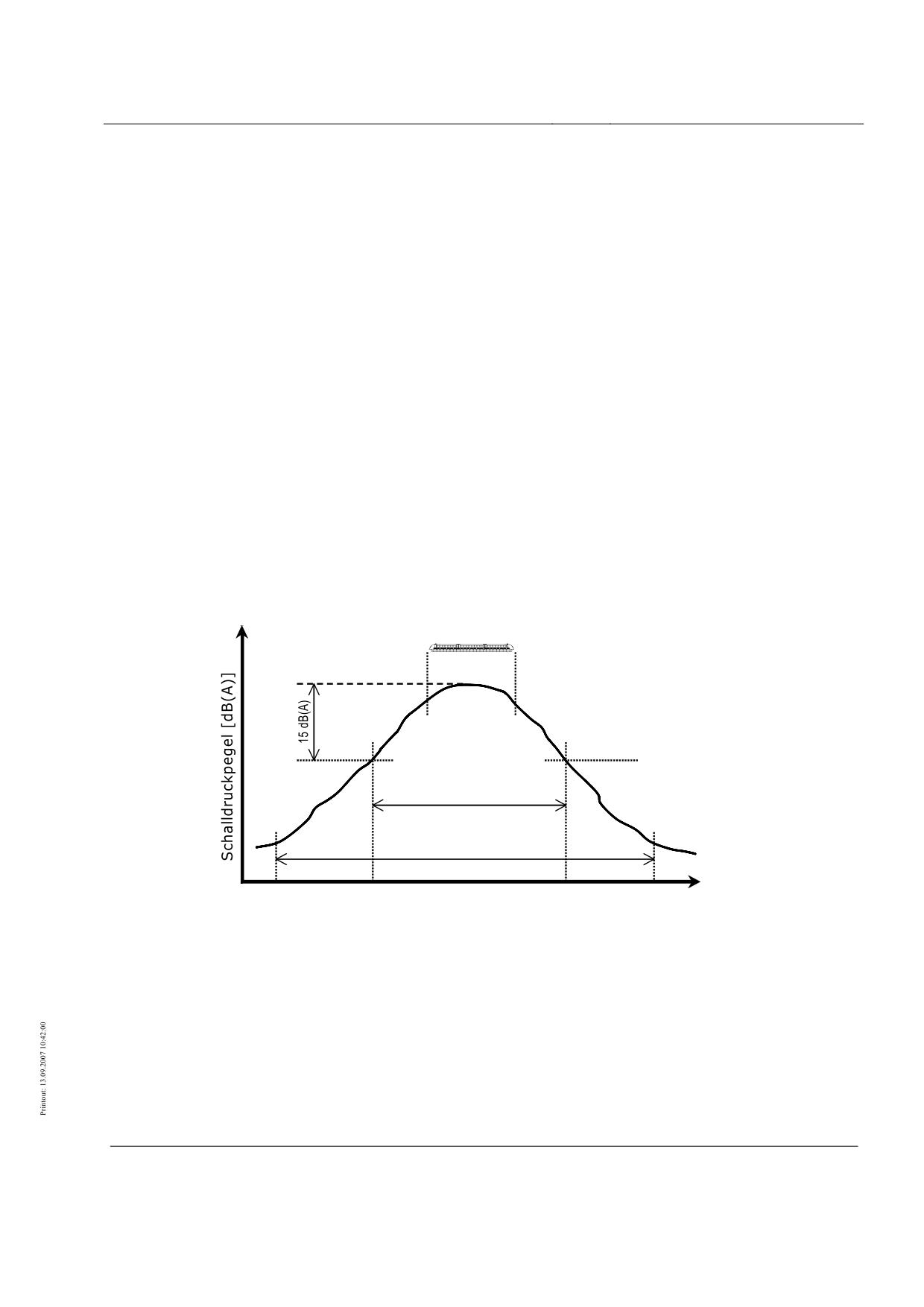
High-speed Maglev System
Maglev Technical Committee
Design Principles
Complete System
Evaluation of measurement data
After taking the measurements in accordance with Chapter 0, analog or digitally stored time
signals of the sound pressure p(t) or time curves of the sound pressure level LA(t) over a suffi-
cient measuring time TM in each case (see Chapter 0) are available for the determination of
both the DFz sound level differences and the DFb sound level difference for specific numbers
of vehicle passes in each case. The evaluation of these measurement data is described in the
present chapter.
Calculation of hourly averaging level
The hourly averaging level LAm,1h shall be calculated for each pass measured and for each
immission location. First the event level LAm,E is calculated by averaging LA(t) over the ave-
raging time TE. Here TE = t2 - t1 is the “event time”, which begins relative to a vehicle pass at
time t1, when the level LA during the vehicle’s approach is for the first time 15 dB(A) below
the maximum level during the vehicle’s passage, and ends at time t2, when after the vehicle’s
passage the level LA has for the last time faded by 15 dB(A) relative to the maximum level.
Figure 40 shows the measuring time TM and the event time TE with times t1 and t2 using the
example of a typical sound level curve LA(t) during the passage of a vehicle.
Maximalpegel
Ereigniszeit TE
Messzeit TM
t1
t2
Zeit [s]
•
Figure 40: Explanation of measuring time TM and event time TE
•
Schalldruckpegel = sound pressure level; Maximalpegel = maximum level; Ereigniszeit = event time;
Messzeit = measuring time; Zeit = time
Title
High-speed Maglev System Design Principles
Complete System Annex 5, Sound
Doc. no.:
72963
Version
White paper Issue date
15.02.2007
Page 21
High-speed Maglev System
Maglev Technical Committee
Design Principles
Complete System
The hourly averaging level follows from the event level LAm,E by adding the term
10lg(TE/3600 s), the result being mathematically rounded to one decimal place. The hourly
averaging levels LAm,1h thus calculated for one pass per hour in each case constitute the basis
for determination of the DFz and DFb sound level differences in Chapter 0.
Additional terms of reference for evalua-
tions with short laid lengths of guideway
test specimen
Separate terms of reference shall be observed with regard to evaluation of the sound pressure
signals p(t) or sound level patterns LA(t) recorded by the measurement method using single
microphones at a reduced measuring distance according to Chapter 0 and by the array method
according to Chapter 0, as described in the following two chapters.
Data evaluation in the measuring method with single mi-
crophones at a reduced measuring distance
In the present measuring method the hourly averaging level LAm,1h is calculated in principle as
described in Chapter 0, but a reduced event time TE,r = t2,r - t1,r is introduced. Here t1,r is the
time at which the vehicle nose reaches the guideway test specimen, and t2,r the time at which
the rear end of the vehicle leaves the guideway test specimen. This definition of times t1,r and
t2,r ensures that during the event time at least one part of the vehicle is travelling over the gui-
deway test specimen. By averaging over the time TE,r, first the event level LAm,E,r is calculated,
then the hourly averaging level LAm,1h,r by adding the term 10lg(TE,r /3600 s) and mathematical
rounding to one decimal place.
The hourly averaging level LAm,1h,r for the top and bottom immission location shall be given
for each vehicle pass. For reasons of comparability, the hourly averaging levels at the measu-
ring location shall be determined with the reference concrete guideway under the same geo-
metric conditions as with measurement at the guideway test specimen, i.e. the extension of the
reference concrete guideway on either side of the measurement cross-section shall be assumed
to be identical with the extension of the guideway test specimen on either side of the measu-
rement cross-section. From this it follows that the difference t2,r - t1,r and therefore the event
time TE,r are the same at both measuring locations. The hourly averaging levels LAm,1h,r thus
calculated at the reference concrete guideway and the guideway test specimen are the input
variables for the determination of DFb in Chapters 0 and 0.
Data evaluation in the array measurement method
The recorded signals of the 27 microphones in the WH10x array shall be evaluated separately
without using shading factors by means of the “delay-and-sum beam forming” algorithm (see
I.E. Johnson and D. E. Dudgeon, Array Signal Processing: Concepts and Techniques, P T R
Prentice Hall, 1993) in the time range for each of the 10 sub-arrays. Table 0-1 shows the as-
signment of individual microphones to the sub-arrays. When calculating the composite array
signals, the requisite sampled values of the microphone signals shall be generated by linear
Title
High-speed Maglev System Design Principles
Complete System Annex 5, Sound
Doc. no.:
72963
Version
White paper Issue date
15.02.2007
Page 22
High-speed Maglev System
Maglev Technical Committee
Design Principles
Complete System
interpolation of the real time signal sample values. The results of beam forming in the indivi-
dual sub-arrays apply to the frequency ranges listed in Table 0-1. The WH10x array conse-
quently accounts for the total frequency range of 125 to 8000 Hz sufficient for the determina-
tion of DFb .
Sub-array
Contains microphones numbered
Frequency range [Hz]
WH128
1, 2, 4, 14, 24, 26, 27
125 - 250
WH096
2, 3, 5, 14, 23, 25, 26
250 - 355
WH064
3, 4, 6, 14, 22, 24, 25
355 - 500
WH048
4, 5, 7, 14, 21, 23, 24
500 - 710
WH032
5, 6, 8, 14, 20, 22, 23
710 - 1000
WH024
6, 7, 9, 14, 19, 21, 22
1000 - 1410
WH016
7, 8, 10, 14, 18, 20, 21
1410 - 2000
WH012
8, 9, 11, 14, 17, 19, 20
2000 - 2820
WH008
9, 10, 12, 14, 16, 18, 19
2820 - 4000
WH004
10, 11, 12, 13, 14, 15, 16, 17, 18
4000 - 8000
•
Table 0-1: Sub-arrays of the WH10x array with associated microphones and frequency ranges
The evaluation mode chosen during beam forming shall be a fixed focus with vertical a-
lignment to the line of microphones. Here - in accordance with the positioning of the array
during measurements - the focal point shall be 25 m from the array. Data evaluation shall be
carried out at each sub-array for measuring and focal points at 1.0 m intervals along the pas-
sing vehicle, i.e. at time intervals corresponding to the progression of the vehicle by 1.0 m at
the current vehicle velocity. At each of these measuring points the composite array signal
shall again be averaged over a time which equals the progression of the vehicle by 5.0 m.
Data evaluation shall commence approx. 100 m in front of the vehicle nose and finish approx.
100 m behind the end of the vehicle. The trigger signal recorded at the same time serves to
link the vehicle position with the sound pressure signals.
The sound level patterns thus calculated and also A-rated for each sub-array in the part fre-
quency ranges of Table 0-1 shall then be energetically totalled, thus giving the time curve of
the sound pressure level in the 125 to 8000 Hz frequency range measured by the WH10x array
for the relevant vehicle pass. In the array method the determination of the associated event
level is linked to the “extended vehicle length” “(evl)”, i.e. with the length of the vehicle ex-
tended by 24.0 m: the event time TE,evl commences at time t1,evl, at which the nose of the ve-
hicle is still 12.0 m in front of the measurement cross-section, and finishes at time t2,evl, at
which, once the vehicle has passed, its rear end is 12.0 m away from the measurement cross-
section. By averaging over the event time TE,evl = t2,evl - t1,evl first the event level LAm,E,evl, then
the hourly averaging level LAm,1h,evl is calculated by adding 10lg(TE,evl /3600 s) and mathema-
tical rounding to one decimal place.
The method of data evaluation thus described shall be applied equally to the measurements at
the vehicle test specimen as well as at the reference concrete guideway. The relevant hourly
averaging levels LAm,1h,evl are the input variables for the determination of DFb in Chapters 0
and 0.
Title
High-speed Maglev System Design Principles
Complete System Annex 5, Sound
Doc. no.:
72963
Version
White paper Issue date
15.02.2007
Page 23
High-speed Maglev System
Maglev Technical Committee
Design Principles
Complete System
Documentation for measurement data
evaluation
The results of the measurement data evaluation carried out in accordance with Chapters 0 and
0 shall be fully documented in tabular form in the measurement report, i.e. for each measured
pass and for each immission location the vehicle velocity, the event time TE (and TE,r or
TE,evl), the event level LAm,E (and LAm,E,r or LAm,E,evl) and the hourly averaging level LAm,1h
(and LAm,1h,r or LAm,1h,evl) shall be given, the vehicle velocity being the velocity notified for the
measuring point by the operator of the maglev section. Results of passes in which the calcula-
ted levels appear doubtful owing to an obvious measuring error shall still be listed in the table,
but shall be highlighted. However they shall not be taken into account when determining DFz
and. DFb in Chapter 0. The causes of the measuring error shall be described.
In addition to the above documentation of the measurement results in tabular form, the curves
LA(t) for all the passes and for each immission location shall be represented in graph form
over the measuring period TM. In this sound level recording the times t1 and t1,r , t2 and t2,r
shall be identified for calculation of the event level. When measurements are made with the
microphone array, the time curves of the composite array signal calculated according to Chap-
ter 0 with the times t1,evl and t2,evl shall be logged as sound level recording LA(t). The represen-
tation of the most recent sound level recording may be restricted to the area approx. 100 m in
front of the nose of the vehicle to approx. 100 m behind the end of the vehicle instead of the
measuring time TM.
Furthermore, sound pressure third-octave spectra shall be compiled in absolute levels from the
25 Hz third-octave centre frequency to the 10 kHz third-octave centre frequency - but in the
array method only for the third octaves from 160 to 6300 Hz. For this the evaluation of each
run at 150, 200, 250, 300 and, depending upon the requisite velocity range, 350 and 400 km/h
is sufficient. For the third-octave spectra the time signal p(t) - in the array method the compo-
site signal of the time signals p(t) of the array microphones - shall be evaluated over the event
time of the relevant pass. The representation of unrated or A-rated third-octave spectra is
permissible; the corresponding choice shall be made clear in the ordinate labelling. Each
third-octave spectrum must, moreover, give the “linear”, i.e. unrated and A-rated total sound
level as the energetic sum of the aforementioned third-octave levels.
Title
High-speed Maglev System Design Principles
Complete System Annex 5, Sound
Doc. no.:
72963
Version
White paper Issue date
15.02.2007
Page 24
High-speed Maglev System
Maglev Technical Committee
Design Principles
Complete System
Determination of DFz and DFb sound level differences
The LAm,1h hourly averaging levels for the individual vehicle passes calculated according to
Chapter 0 are the basis for determining DFz sound level differences, i.e. DFz,me and DFz,ae desc-
ribed below, as well as the DFb sound level difference.
Determination of DFz,me and DFz,ae values
To determine DFz,me and DFz,ae values only the measurement results for the passes on the refe-
rence concrete guideway according to Chapter 0 shall be used under the measurement condi-
tions also given in this chapter. As, according to Chapter 0, the length of the vehicle and its
number of sections is optional in measurements to determine DFz, with reference to the mea-
sured hourly averaging levels LAm,1h this means a necessary correction by values ∆LSec, which
depend on the number of sections and the vehicle velocity and are given below for 2- to 10-
section vehicles.
NB: The compilation of /MSB-LSV/ was based on measured immission levels from passes of
the TR 07/1 comprising two sections. Values for multiple-section vehicles were predicted with
the aid of model calculations based on a sound source location on the TR 07/1. These predic-
ted values were used as substitutes for the missing measurements for multi-section vehicles
and used to compile the formulae (2.1) and (2.2) in /MSB-LSV/ for taking the vehicle length
into consideration. Within this method the immission levels during the measurement and mo-
del calculations were below the arithmetic values then laid down in /MSB-LSV/ (by up to
1.2 dB(A) for a 2-section vehicle and by up to 2.1 dB(A) for a 4-section vehicle). These diffe-
rences were accepted as a conservative assessment and are reflected in the∆LSec correction
values.
The ∆LSec values for correction of the measured LAm,1h hourly averaging levels are given by
Equations (1a-1i), and in the calculation below shall be mathematically rounded to two deci-
mal places:
∆LSec(2 sections,v) = -2.7 + 16.5 ⋅ lg(v/v0) - 17.9 ⋅ (lg(v/v0))2 [dB(A)],
(1a)
∆LSec(3 sections,v) = -2.5 + 17.5 ⋅ lg(v/v0) - 18.7 ⋅ (lg(v/v0))2 [dB(A)],
(1b)
∆LSec(4 sections,v) = -2.4 + 18.4 ⋅ lg(v/v0) - 19.6 ⋅ (lg(v/v0))2 [dB(A)],
(1c)
∆LSec(5 sections,v) = -2.4 + 19.0 ⋅ lg(v/v0) - 19.5 ⋅ (lg(v/v0))2 [dB(A)],
(1d)
∆LSec(6 sections,v) = -2.4 + 19.5 ⋅ lg(v/v0) - 19.4 ⋅ (lg(v/v0))2 [dB(A)],
(1e)
∆LSec(7 sections,v) = -2.4 + 19.4 ⋅ lg(v/v0) - 18.7 ⋅ (lg(v/v0))2 [dB(A)],
(1f)
∆LSec(8 sections,v) = -2.3 + 19.3 ⋅ lg(v/v0) - 18.0 ⋅ (lg(v/v0))2 [dB(A)],
(1g)
∆LSec(9 sections,v) = -2.3 + 18.9 ⋅ lg(v/v0) - 17.0 ⋅ (lg(v/v0))2 [dB(A)],
(1h)
∆LSec(10 sections,v) = -2.2 + 18.5 ⋅ lg(v/v0) - 16.0 ⋅ (lg(v/v0))2 [dB(A)].
(1i)
•
Equations (1a-1i)
NB: Equations (1a-1i) are based on a section length of approx. 25 m. Should the section
length deviate substantially from this, the equation for the nearest vehicle length shall be u-
sed.
Accordingly the corrected LAm,1h,corr hourly averaging levels for the measured passes at the
relevant velocity v with ∆LSec for the number of sections during measurement are
LAm,1h,corr = LAm,1h + ∆LSec [dB(A)].
(2)
Title
High-speed Maglev System Design Principles
Complete System Annex 5, Sound
Doc. no.:
72963
Version
White paper Issue date
15.02.2007
Page 25
High-speed Maglev System
Maglev Technical Committee
Design Principles
Complete System
•
Equation (2)
The next thing to determine, on the basis of the thus corrected LAm,1h,corr hourly averaging le-
vels available in 10 km/h steps from 130 to at least 400 km/h, is an equalising second grade
polynomial of the form
LAm,1h,corr(v) = a + b ⋅ lg(v/v0) + c ⋅ (lg(v/v0))2 [dB(A)],
(3)
•
Equation (3)
the coefficients a, b and c being calculated by the smallest error square method and the vehic-
le velocities of the individual LAm,1h,corr hourly averaging levels being the velocities given by
the operator of the maglev sector. The polynomial LAm,1h,corr(v) is the representative of the
measured values in the following. It is basically only valid within the range of the velocities
measured. An exception, however, is the velocity range below 170 km/h where, according to
the ruling in /MSB-LSV/ sub-section 2.5, the hourly averaging levels shall be set to the value
at 170 km/h. Furthermore, in cases where LAm,1h,corr hourly averaging levels above the pass
measured at the highest velocity are required, these may be extrapolated by using the polyno-
mial up to velocities which are no more than 5 % higher than the highest measured velocity.
Determination of the values of DFz,me and DFz,ae is carried out as part of the iterative procedure
described below. Here the levels of the polynomial LAm,1h,corr(v) are compared with those of
the total rating sound level Lr(v) calculated according to /MSB-LSV/. To do this the total ra-
ting sound level is calculated as the energetic sum of the mechanical and aerodynamic rating
sound level for different combinations of DFz,me and DFz,ae for the period of one hour for one
pass in this time by means of the part-section method for the geometric situation when taking
the measurement at the reference concrete guideway. Here part sections over a length of at
least 500 m on both sides of the measurement cross-section shall be included. When calcula-
ting the rating sound level, the correction level S allowing for the special features of railways
(see /MSB-LSV/) shall be ignored.
The iteration method comprises the following part steps:
1) Calculation of the total rating sound level Lr(v) for a combination of DFz,me and
DFz,ae values,
2) Calculation of the sound level differences ∆LDiff(v) between the calculated total
rating sound level Lr(v) and the polynomial LAm,1h,corr(v) in the velocity range of
170 km/h to at least 400 km/h in steps of 1 km/h according to
∆LDiff(v) = Lr(v) - LAm,1h,corr(v) [dB(A)],
(4)
•
Equation (4)
3) Mathematical rounding of the values of ∆LDiff(v) to one decimal place,
4) Variation of the DFz,me and DFz,ae values in 0.5 dB steps to determine the
com-
bination of values at which both the following conditions are met:
a) The rounded sound level differences ∆LDiff (v) ≥ 0 for all the velocities between
170 km/h and the highest velocity (at least 400 km/h, see Chapter 0); this con-
dition shall be checked at 1 km/h steps to ensure that the predicted total rating
Title
High-speed Maglev System Design Principles
Complete System Annex 5, Sound
Doc. no.:
72963
Version
White paper Issue date
15.02.2007
Page 26
High-speed Maglev System
Maglev Technical Committee
Design Principles
Complete System
sound levels always lie above the measured values (represented by the values
of the polynomial LAm,1h,corr(v)).
b) In the range from 170 km/h to the highest velocity (at least 400 km/h, see
Chapter 0), the sum of the squares of the rounded ∆LDiff(v) sound level diffe-
rences is minimal. When calculating this sum the graduation is again 1 km/h.
The combination of DFz values found on completion of step 4 of the iteration process repre-
sents the values for DFz,me und DFz,ae sought for a new vehicle.
Determination of the DFb value
Determination of the DFb value assumes knowledge of the DFzH auxiliary variables, i.e. of
DFzH,me and DFzH,ae, of the vehicle with which the passes on the guideway test specimen were
carried out and for which the DFb value is to be determined. Here the DFzH values in principle
represent the DFz sound level differences; however they are determined without the ∆LSec cor-
rections relating to the number of sections. In general they are based on preliminary measu-
rements at the reference concrete guideway taken just prior to the actual measurements at the
guideway test specimen.
Preliminary measurements and data evaluation for determination of DFzH values
The preliminary measurements to determine the DFzH values on the reference concrete guide-
way are subject to the requirements given in Chapter 0. Even evaluation of the measurement
data does not differ from that for the determination of DFz. The calculation of DFzH,me and
DFzH,ae is therefore carried out analogously using the iteration method from Chapter 0. Howe-
ver four exceptions should be noted here:
• The LAm,1h hourly averaging levels are not acted upon by the correction values ∆LSec,
so that the equalising polynomial from Equation (3) is derived from the values actually
measured for the hourly averaging levels.
• The rounding of ∆LDiff (v) in step 3 of the iteration process is omitted.
• In step 4 of the iteration process the variation of the DFzH,me and DFzH,ae values is car-
ried out in 0.1 dB steps and
• the condition ∆LDiff (v) ≥ 0 is not applicable.
The combination of DFzH values found on completion of step 4 of the iteration process repre-
sents the values sought for DFzH,me and DFzH,ae.
Title
High-speed Maglev System Design Principles
Complete System Annex 5, Sound
Doc. no.:
72963
Version
White paper Issue date
15.02.2007
Page 27
High-speed Maglev System
Maglev Technical Committee
Design Principles
Complete System
Determination of DFb value on the basis of DFzH values
To determine the DFb value of the guideway test specimen, the differential curve ∆LAm,1h(v) is
first created from the LAm,1h,test hourly averaging levels measured at the measuring location
with the guideway test specimen and from the LAm,1h,ref sound levels measured at the reference
location with the reference concrete guideway in the velocity range common to both measu-
ring locations, namely
∆LAm,1h(v) = LAm,1h,test(v) - LAm,1h,ref(v) [dB(A)],
(5)
•
Equation (5)
where LAm,1h,test(v) and LAm,1h,ref(v) are equalising polynomials to be determined according to
Equation (3). The curve path ∆LAm,1h(v) is therefore representative of the sound level diffe-
rence determined at the immission location with the guideway test specimen relative to the
immission location with the reference concrete guideway subject to the velocity. Knowing the
auxiliary variables DFzH,me and DFzH,ae of the current vehicle, i.e. the vehicle with which the
passes on the guideway test specimen were carried out, the DFb value of the guideway test
specimen, i.e. DFb,test, is calculated using Equation (6):
(∆L
Am,1h
−C)/10
(∆L
Am,1h
−C+L
E,ae
−L
E,me
)/10
(L
E,ae
−L
E,me
)/10
D
(v)
=10lg(0
+10
−10
)
[dB(A)]
Fb,test
(6)
•
Equation (6)
where LE,me = 40 + DFzH,me + 10lg(l/100 m) + 20lg(v/v0) + DFb,ref [dB(A)],
LE,ae = 24 + DFzH,ae + 10lg((0.6⋅l + 40)/100 m) + 60lg(v/v0) [dB(A)],
DFb,ref = 0
C = Ctest - Cref [dB(A)],
L
k,test
/10
C
=10lg
test
∑10∆
k
where
[dB(A)] (according to the part-section method of
/MSB-LSV/),
∆L
k,ref
/10
C
=
10lg
10
∑
ref
k
[dB(A)] (according to the part-section method of
MSB-LSV/),
where ∆Lk,test = 18 + 10lg(lk,test) + Ds,k,test + DL,k,test + DBM,k,test [dB(A)],
∆Lk,ref = 18 + 10lg(lk,ref) + Ds,k,ref + DL,k,ref + DBM,k,ref [dB(A)].
NB: The terms Ctest and Cref allow for different above-ground heights of the guideway top
edge and of the immission location at the measuring point of the guideway test specimen and
the reference concrete guideway. If the heights of the top guideway edge at both measuring
locations are the same, the difference Ctest - Cref is zero, so that term C in Equation (6) is not
applicable.
Equation (6) applies expressly only to the boundary conditions to be observed during measu-
rements under the terms of reference in Chapter 0. It should again be noted that in (6) part-
sections over a length of at least 500 m on either side of the measurement cross-section must
be included within the framework of the part-section method.
The maximum value of DFb,test determined according to Equation (6) in the velocity range
from 170 km/h onwards shall be rounded up in 0.5 dB steps. The resultant value represents
the sought DFb value of the guideway test specimen. According to Chapter 0 it is permissible
to give the DFb value of the guideway test specimen in velocity ranges, namely up to and inc-
Title
High-speed Maglev System Design Principles
Complete System Annex 5, Sound
Doc. no.:
72963
Version
White paper Issue date
15.02.2007
Page 28
High-speed Maglev System
Maglev Technical Committee
Design Principles
Complete System
luding 300 km/h, from > 300 km/h up to and including 400 km/h and in the range above that,
so the determination of DFb by means of Equation (6) shall if necessary be carried out separa-
tely in the individual velocity ranges. The DFb values thus obtainable shall be identified in
relation to their scope.
Additional terms of reference for the determina-
tion of DFb on short laid lengths of the guide-
way test specimen
The greater value determined in each case from the single microphone method at a reduced
measuring distance and the array method is set as the DFb value of the guideway test speci-
men. This rule applies to the total velocity range from 170 km/h onwards, and also separately
for the partial velocity ranges possible according to Chapter 0. The following details should
also be noted:
• The determination of DFb by the single microphone method at reduced measuring di-
stance is effected in principle as described in Chapter 0. However, for the ∆LAm,1h(v)
sound level differences in Equation (5), when calculating the polynomials LAm,1h,test(v)
and LAm,1h,ref(v) according to Equation (3), all the LAm,1h,r hourly averaging levels de-
termined at one measuring point, i.e. the levels from both immission heights, are inc-
luded at the same time. If term C in Equation (6) has to be taken into account due to
the different heights of the immission locations at both measuring locations, the height
of the immission location for each measuring location required to calculate Ctest and
Cref shall be averaged from both immission location heights of each measuring locati-
on.
• The determination of DFb by the array method is effected congruently as described in
Chapter 0. The LAm,1h,evl hourly averaging levels are used when calculating the poly-
nomials LAm,1h,test(v) and LAm,1h,ref(v) according to Equation (3).
NB: By taking into account the hourly averaging levels measured in two immission location heights by the single microphone
method, the averaging obtained in the polynomial calculation for each measuring location reduces the errors caused by the
vertical directional characteristic of guideway and vehicle.
Documentation for determination of DFz and
DFb sound level differences
The documentation relating to the values for DFz,me and DFz,ae for a new vehicle found by the
iterative method in Chapter 0 comprises two graphs intended to illustrate the “best” ad-
justment of the total rating sound levels calculated according to /MSB-LSV/ to the corrected
hourly averaging levels measured at the reference concrete guideway. The first graph shall
compare:
• the individual corrected LAm,1h,corr hourly averaging levels,
• the equalising polynomial LAm,1h,corr(v) derived from these values, and
Title
High-speed Maglev System Design Principles
Complete System Annex 5, Sound
Doc. no.:
72963
Version
White paper Issue date
15.02.2007
Page 29
High-speed Maglev System
Maglev Technical Committee
Design Principles
Complete System
• the curve of the total rating sound level Lr(v) calculated according to /MSB-LSV/.
Plotted in the second graph is the curve of the ∆LDiff(v) sound level difference according to (4)
which led to discontinuation of the iteration process.
As part of the determination of the DFb value for the guideway test specimen, a graph is first
drawn by analogy with the determination of DFz values in respect of the values for DFzH,me and
DFzH,ae resulting from the iteration process according to Chapter 0. This graph shall show
• the individual measured hourly averaging levels LAm,1h,
• the equalising polynomial LAm,1h(v) derived from these values, and
• the curve of the total rating sound level Lr(v) calculated according to /MSB-LSV/ with
DFzH,me for DFz,me and DFzH,ae for DFz,ae
for the case of “best” adjustment of the total rating sound level to be calculated and the hourly
averaging levels measured. This “best” adjustment shall be illustrated by another graph in
which is plotted the curve of the ∆LDiff(v) sound level difference according to (4) which led
to discontinuation of the iteration process.
Furthermore, the measured values at the guideway test specimen shall be recorded in a graph
• the individual measured LAm,1h,test hourly averaging levels and
• the equalising polynomial LAm,1h,test(v) derived from these values.
To record the DFb value determined by means of Equation (6), two graphs shall be drawn
showing
• the measured ∆LAm,1h sound level difference as a function of velocity, and
• the calculated DFb,test values as a function of velocity
in the velocity range from 170 km/h onwards. On the one hand the latter graph illustrates the
dependence of the DFb,test values on the velocity of the vehicle, on the other it shows the velo-
city at which the maximum value of DFb,test , and hence ultimately the DFb value, of the guide-
way test specimen was determined.
Title
High-speed Maglev System Design Principles
Complete System Annex 5, Sound
Doc. no.:
72963
Version
White paper Issue date
15.02.2007
Page 30
High-speed Maglev System
Maglev Technical Committee
Design Principles
Complete System
Annex
In this Annex an example is used to illustrate the determination of DFz-, DFzH- and DFb values
and the result documentation. Table 0-1 lists hypothetical LAm,1h hourly averaging levels
which should have been measured under conditions according to Chapter 0 at the reference
concrete guideway and determined according to the terms of reference given in Chapter 0.
The present example assumes the following boundary conditions and hypothetical readings:
• single microphone at a distance of 25 m from the guideway support centre
• “long” extension of guideway,
• top guideway edge in the measurement cross-section at a height of 6.7 m above the
ground,
• vehicle of 79.2 m in length.
v
LAm,1h
v
LAm,1h
v
LAm,1h
[km/h]
[dB(A)]
[km/h]
[dB(A)]
[km/h]
[dB(A)]
129.9
41.9
229.2
46.6
330.1
53.6
130.0
42.5
230.3
46.8
330.5
53.8
139.9
42.5
240.1
47.4
339.9
54.4
140.1
42.2
240.3
47.9
340.3
54.8
150.1
41.9
249.9
48.2
349.7
55.3
150.4
42.5
250.3
48.5
350.1
55.1
160.0
42.3
260.2
48.8
360.1
55.6
160.1
42.7
260.5
49.2
360.4
55.2
170.1
42.6
269.8
49.7
369.7
56.5
170.4
43.4
270.2
50.3
370.1
56.3
180.1
43.5
280.0
50.2
379.7
56.8
180.2
42.7
280.2
50.5
380.1
56.7
190.1
43.6
289.9
51.2
390.0
57.0
190.3
44.4
290.2
51.5
390.2
57.4
200.1
44.4
300.2
51.9
400.1
58.0
200.3
44.7
300.6
52.3
400.3
57.7
210.2
44.9
310.5
52.3
409.6
58.4
210.4
45.1
310.8
52.6
409.9
58.9
219.8
45.9
319.9
52.8
410.3
58.6
220.2
45.5
320.1
53.1
-
-
•
Table 0-1: Hourly averaging levels hypothetically determined at the measuring location with the reference
concrete guideway
Title
High-speed Maglev System Design Principles
Complete System Annex 5, Sound
Doc. no.:
72963
Version
White paper Issue date
15.02.2007
Page 31
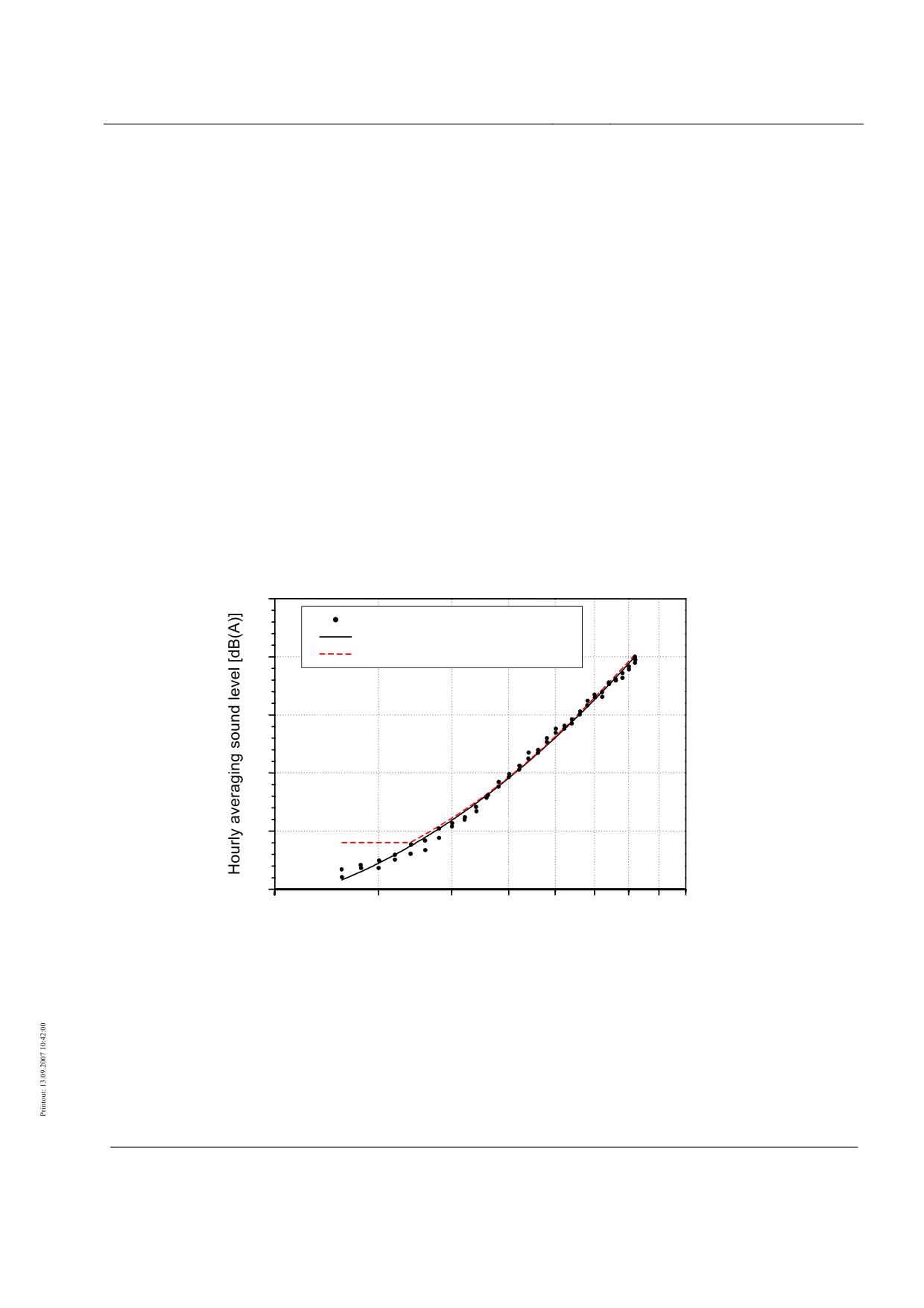
High-speed Maglev System
Maglev Technical Committee
Design Principles
Complete System
Example for determination of DFz sound level
differences DFz,me and DFz,ae
The LAm,1h hourly averaging levels from Table 0-1 are first corrected with regard to the num-
ber of sections of the vehicle according to Equation (2). The resultant LAm,1h,corr hourly avera-
ging levels are entered in Figure 41 (in accordance with Chapter 0). From the LAm,1h,corr levels
the equalising polynomial LAm,1h,corr(v) is then formed according to Equation (3) and added to
Figure 41 (see Chapter 0). In the present example the values a = 38.90, b = 12.62 and
c = 35.70 are obtained for the coefficients of the equalising polynomials.
By applying the iteration process set out in Chapter 0, the DFz,me and DFz,ae values are determi-
ned which deliver the “best” adjustment of the Lr(v) total rating sound level calculated in ac-
cordance with /MSB-LSV/ to the equalising polynomial LAm,1h,corr(v), special note being taken
of the fact that the calculated total rating sound level must always be above the equalising
polynomial. In this example the values determined are DFz,me = -0.5 dB(A) and DFz,ae = -
0.5 dB(A). The curve of the total rating sound level for both these values is also entered in
Figure 41 (see Chapter 0).
For the rest, the value for Cref needed for calculation of the total rating sound level at the refe-
rence concrete guideway based on the geometric conditions given above and the part sections
taken into consideration over ± 500 m on either side of the measurement cross-section is
0.0218 dB(A).
65
Corrected reading
Equalising polynomial
60
Total rating sound level
55
50
45
40
100
150
200
250
300
350
400
450
500
Velocity v [km/h]
•
Figure 41: Corrected LAm,1h,corr hourly averaging levels, equalising polynomial LAm,1h,corr(v) and total rating
sound level Lr(v) based on the DFz values determined by the iteration method
According to the terms of reference in Chapter 0, in Figure 42 the curve of the ∆LDiff sound
level differential according to Equation (4) is shown as the difference of the total rating sound
level and equalising polynomial curves from Figure 41. Figure 42 serves as proof that in the
determination of DFz,me and DFz,ae the condition ∆LDiff ≥ 0 was complied with the total velocity
range from 170 km/h to the maximum velocity.
Title
High-speed Maglev System Design Principles
Complete System Annex 5, Sound
Doc. no.:
72963
Version
White paper Issue date
15.02.2007
Page 32
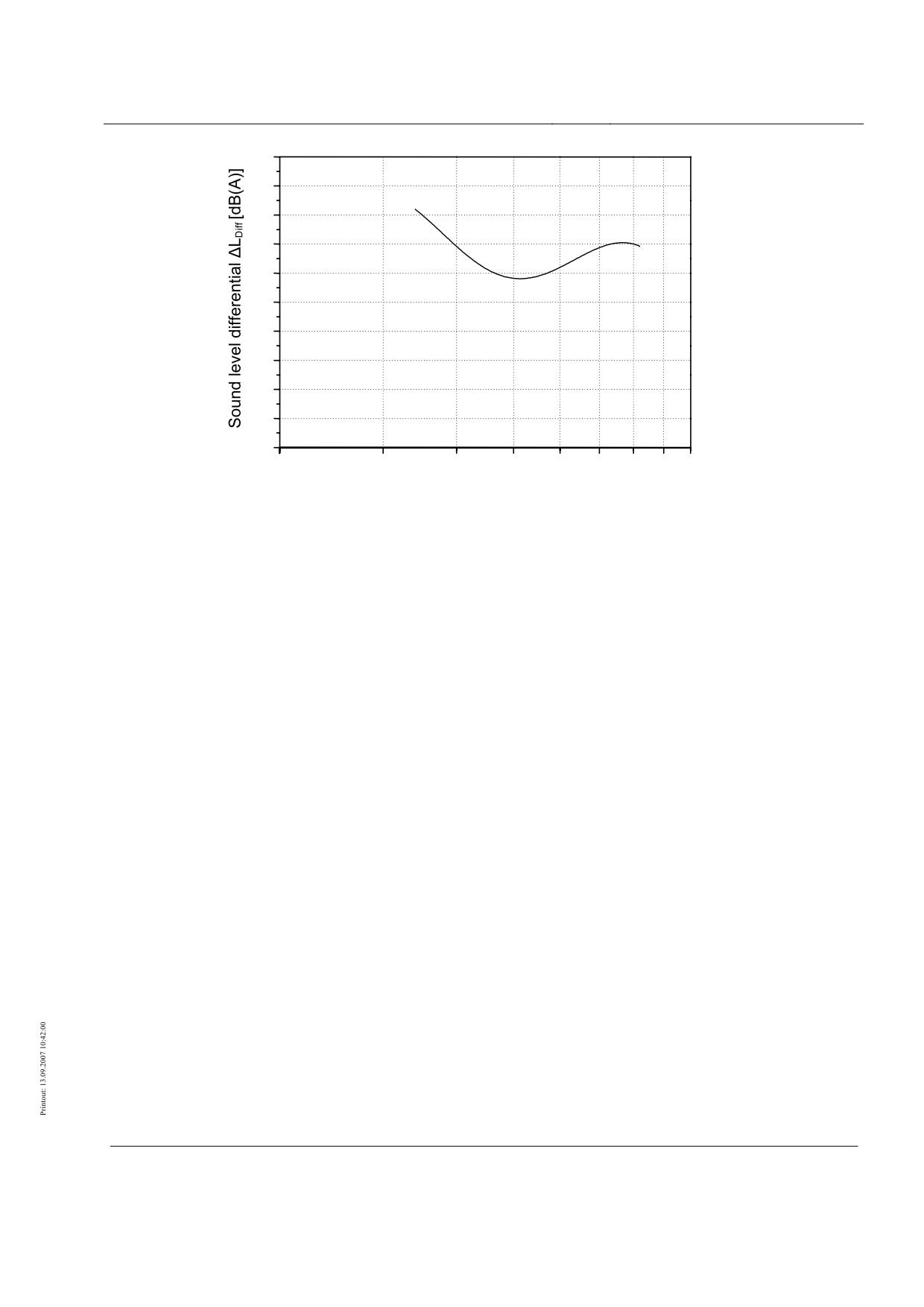
High-speed Maglev System
Maglev Technical Committee
Design Principles
Complete System
0.5
0.4
0.3
0.2
0.1
0.0
-0.1
-0.2
-0.3
-0.4
-0.5
100
150
200
250
300
350
400
450
500
Velocity v [km/h]
•
Figure 42: Sound level difference ∆LDiff(v) of total rating sound level and equalising polynomial from
Figure 41
Example for determination of sound level
difference DFb
In a first step, measurements are taken at the reference guideway to determine for the vehicle
the auxiliary variables DFzH,me and DFzH,ae at which the runs on the guideway test specimen
were carried out. The sound level difference DFb is then determined from the difference bet-
ween the hourly averaging levels measured at the guideway test specimen and at the reference
concrete guideway.
Determination of auxiliary variables DFzH,me and DFzH,ae
First, in accordance with Chapter 0, the hourly averaging levels LAm,1h = LAm,1h,ref from Table
0-1 determined at the reference concrete guideway are represented by a graph (see Figure 43).
No correction is made in respect of the number of vehicle sections. An equalising polynomial
LAm,1h,ref(v) is adjusted to these values using Equation (3) and also represented by a graph (see
Figure 43). In the example the values given for the coefficients of this equalising polynomial
are a = 41.43, b = -4.81 and c = 54.38.
Using the iteration method modified according to Chapter 0, the auxiliary variables DFzH,me
and DFzH,ae are determined by the “best” adjustment of the Lr(v) total rating sound level to the
equalising polynomial LAm,1h,ref(v) calculated according to /MSB-LSV/. In accordance with
Chapter 0, the curve of Lr(v) in Figure 43 predicted by the values found for DFzH,me and DFzH,ae
is added. In the present example the iteration method gives the values DFzH,me = -1.6 dB(A)
and DFzH,ae = -2.2 dB(A). For the DFzH values thus determined the curve of the ∆LDiff sound
level differential according to Equation (4) is shown in accordance with Chapter 0 in a separa-
Title
High-speed Maglev System Design Principles
Complete System Annex 5, Sound
Doc. no.:
72963
Version
White paper Issue date
15.02.2007
Page 33
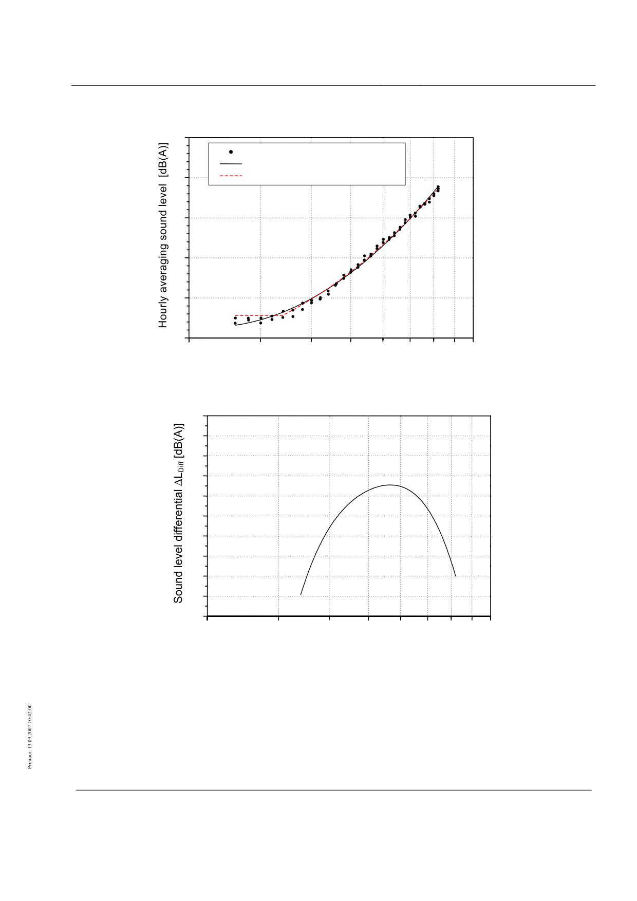
High-speed Maglev System
Maglev Technical Committee
Design Principles
Complete System
te graph (see Figure 44) as the difference of the total rating sound level and equalising poly-
nomial curves from Figure 43.
65
Readings
Equalising polynomial
60
Total rating sound level
55
50
45
40
100
150
200
250
300
350
400
450
500
Velocity v [km/h]
•
Figure 43: LAm,1h,ref hourly averaging level, equalising polynomial LAm,1h,ref(v) and Lr(v) total rating sound
level based on the DFzH values determined by the modified iteration method
0.5
0.4
0.3
0.2
0.1
0.0
-0.1
-0.2
-0.3
-0.4
-0.5
100
150
200
250
300
350
400
450
500
Velocity v [km/h]
•
•
Figure 44: ∆LDiff(v) sound level differential of total rating sound level and equalising polynomial from Figure
43
Title
High-speed Maglev System Design Principles
Complete System Annex 5, Sound
Doc. no.:
72963
Version
White paper Issue date
15.02.2007
Page 34
High-speed Maglev System
Maglev Technical Committee
Design Principles
Complete System
Determination of DFb value for a guideway test specimen
with long extension
Once the auxiliary variables DFzH,me and DFzH,ae are determined, the DFb value of the
guideway test specimen can be calculated using Equation (6). For this Table 0-2 lists hypothe-
tical LAm,1h hourly averaging levels which should have been measured under conditions ac-
cording to Chapter 0 on the guideway test specimen and determined according to the terms of
reference in Chapter 0.
The present example assumes the following boundary conditions and hypothetical readings:
•
single microphone at a distance of 25 m from the guideway support centre,
•
“long” extension of guideway,
•
Top guideway edge in the measured cross-section at a height of 6.5 m above
ground.
v
LAm,1h
v
LAm,1h
v
LAm,1h
[km/h]
[dB(A)]
[km/h]
[dB(A)]
[km/h]
[dB(A)]
130.1
44.6
229.7
49.4
329.8
55.0
130.3
45.0
230.1
49.7
330.4
55.4
139.8
44.9
240.0
50.2
340.0
55.6
140.0
44.6
240.2
50.6
340.4
56.1
149.8
44.3
249.8
50.6
349.9
56.5
150.2
44.8
250.1
51.0
350.3
56.2
159.9
44.6
260.1
51.3
359.8
56.7
160.1
45.0
260.5
51.6
360.3
56.4
170.0
44.9
269.7
51.7
369.7
57.6
170.3
45.6
270.1
52.3
370.3
57.3
179.9
45.8
279.5
52.4
379.9
57.7
180.1
45.1
280.1
52.8
380.2
57.5
189.8
46.0
289.8
53.1
390.1
57.7
190.1
46.9
290.2
53.3
390.4
58.2
199.9
47.0
299.7
53.7
399.8
58.6
200.3
47.4
300.3
54.0
400.4
58.4
210.0
47.8
310.1
54.1
409.6
59.0
210.4
48.1
310.5
54.3
410.0
59.3
219.7
48.8
319.9
54.4
410.4
59.1
220.2
48.5
320.3
54.6
-
-
•
Table 0-2: Hypothetical hourly averaging levels determined at the measuring location with the guideway
test specimen
Title
High-speed Maglev System Design Principles
Complete System Annex 5, Sound
Doc. no.:
72963
Version
White paper Issue date
15.02.2007
Page 35
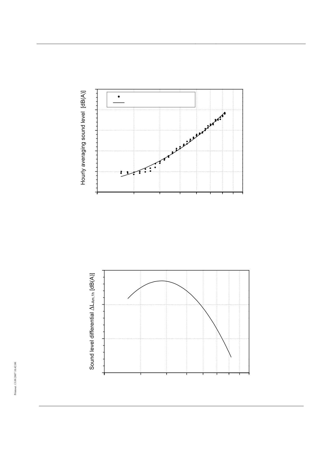
High-speed Maglev System
Maglev Technical Committee
Design Principles
Complete System
The equalising polynomial LAm,1h,test(v) is first formed from the hourly averaging levels
LAm,1h = LAm,1h,test in Table 0-2, and in accordance with Chapter 0 represented together with
the LAm,1h,test sound levels (see Figure 45). In the present example the values for the coeffi-
cients of the equalising polynomial are a = 42.62, b = 6.06 and c = 34.69.
65
Readings
Equalising polynomial
60
55
50
45
40
100
150
200
250
300
350
400
450
500
Velocity v [km/h]
•
Figure 45: LAm,1h,test hourly averaging level and equalising polynomial LAm,1h,test(v)
With the polynomial LAm,1h,ref(v) already calculated above, Equation (5) is used to obtain the
∆LAm,1h(v) sound level differential which represents the input variable for Equation (6) resul-
ting from the measurements. The curve of ∆LAm,1h(v) is represented in a separate graph accor-
ding to Chapter 0 as an important intermediate variable in the determination of DFb (see Figure
46).
3
2
1
0
100
150
200
250
300
350
400
450
500
Velocity v [km/h]
•
•
Figure 46: ∆LAm,1h(v) sound level differential
Title
High-speed Maglev System Design Principles
Complete System Annex 5, Sound
Doc. no.:
72963
Version
White paper Issue date
15.02.2007
Page 36
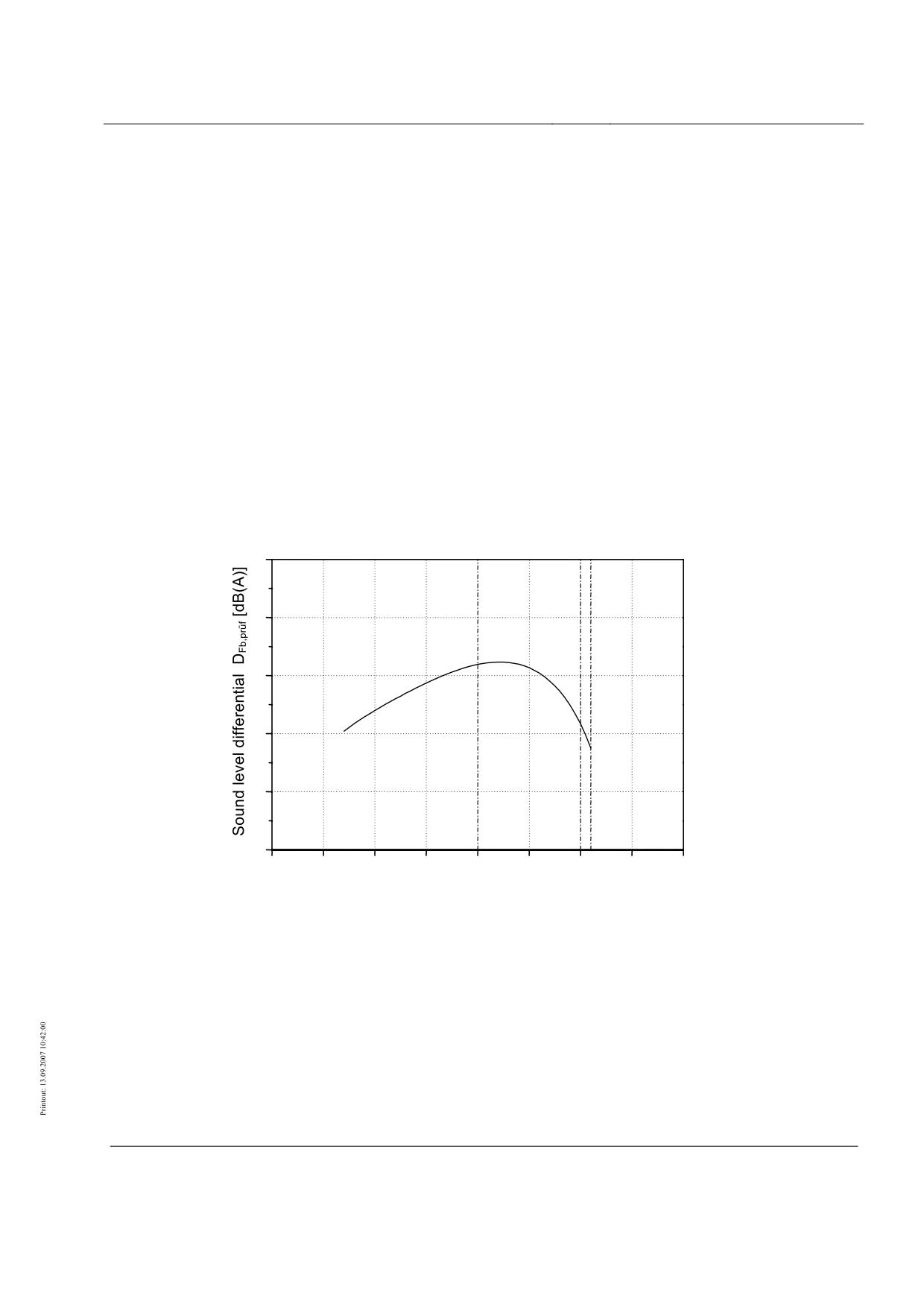
High-speed Maglev System
Maglev Technical Committee
Design Principles
Complete System
The next step is to determine DFb,test(v) from ∆LAm,1h(v) using Equation (6). Here the term
C = Ctest - Cref must be calculated at both measuring locations with due regard to the geometric
circumstances. The value 0.0218 dB(A) was already determined for Cref in Chapter 0 . Due to
the slightly changed geometric situation relative to the reference concrete guideway at the
measuring location with the guideway test specimen (see above) this gives
Ctest = 0.0144 dB(A), so that for C a value of -0.0075 dB(A) is obtained.
In Figure 47, as a result of the calculations using Equation (6), the values of DFb,test(v) are
plotted as a function of vehicle velocity. The DFb value of the guideway test specimen is now
obtained from the maximum value of DFb,test rounded up in 0.5 dB steps, either in the total
velocity range from 170 km/h onwards or in the part ranges possible according to Chapter 0.
In the present example these are:
•
DFb = 4.5 dB(A) in the total velocity range up to 410 km/h,
•
DFb = 4.5 dB(A) in the part range up to 300 km/h,
•
DFb = 4.5 dB(A) in the part range 300 < v ≤ 400 km/h,
•
DFb = 3.5 dB(A) in the part range 400 < v ≤ 410 km/h.
6
5
4
3
2
1
100
150
200
250
300
350
400
450
500
Velocity v [km/h]
•
Figure 47: Calculated DFb,test values of a guideway test specimen for hypothetical measurements on a
specimen with a “long” extension
Title
High-speed Maglev System Design Principles
Complete System Annex 5, Sound
Doc. no.:
72963
Version
White paper Issue date
15.02.2007
Page 37
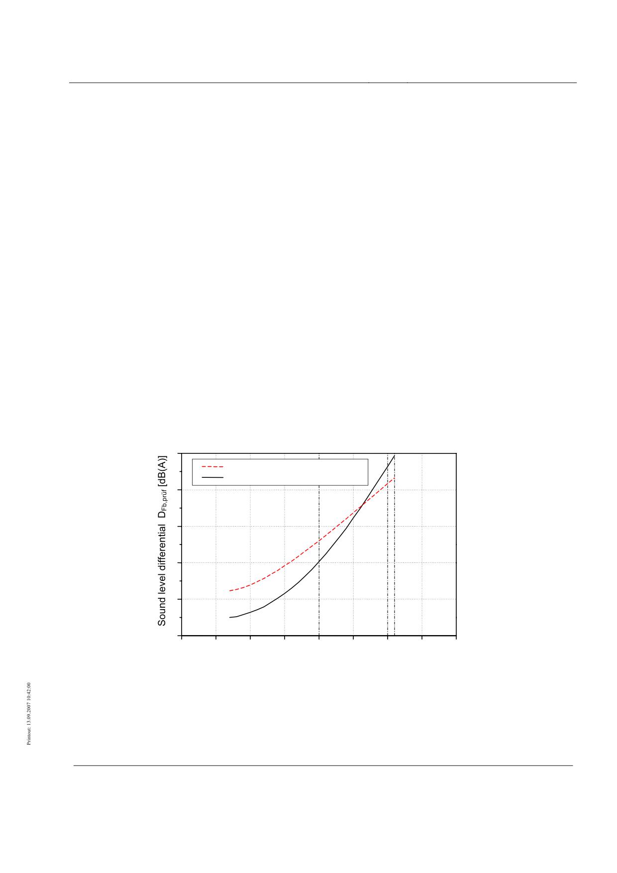
High-speed Maglev System
Maglev Technical Committee
Design Principles
Complete System
Determination of DFb value for a guideway test specimen of
short laid length
Finally, for a guideway test specimen of “short” laid length, Figure 48 shows the example of a
DFb determination result using the single microphone method at a reduced measurement di-
stance and the array method, whereby the terms of reference in Chapter 8.3 shall be noted.
These stipulate in particular that the DFb value of the guideway test specimen shall be the
greater of the two values determined by both methods, both in the total velocity range from
170 km/h onwards and separately in the part velocity ranges. Consequently the DFb value in
the present example after being rounded up in 0.5 dB steps is
•
DFb = 6.0 dB(A) in the total velocity range to 410 km/h, determined from the
single microphone measurement,
•
DFb = 4.0 dB(A) in the part range up to 300 km/h, determined from the array
measurement,
•
DFb = 6.0 dB(A) in the part range 300 < v ≤ 400 km/h, determined from the
single microphone measurement,
•
DFb = 6.0 dB(A) in the part range 400 < v ≤ 410 km/h, determined from the
single microphone measurement.
6
Array method
Single microphone method
5
4
3
2
1
100
150
200
250
300
350
400
450
500
Velocity v [km/h]
•
Figure 48: Calculated DFb,test values of a guideway test specimen for hypothetical measurements on a
specimen of “short” laid length
NB: Re the very different curves of DFb,test as a function of velocity in Figure 47 and Figure
48, it should be noted that Figure 47 reflects a possible case in which the increased sound
emission of the guideway test specimen is based solely on an additional proportion with a
Title
High-speed Maglev System Design Principles
Complete System Annex 5, Sound
Doc. no.:
72963
Version
White paper Issue date
15.02.2007
Page 38
High-speed Maglev System
Maglev Technical Committee
Design Principles
Complete System
mechanical cause. In the hypothetical case of Figure 48, on the other hand, both mechanical
and aerodynamic causes are responsible for the greater radiation of the test specimen.
Title
High-speed Maglev System Design Principles
Complete System Annex 5, Sound
Doc. no.:
72963
Version
White paper Issue date
15.02.2007
Page 39
High-speed Maglev System
Maglev Technical Commit-
tee
Design Principles
Vehicle
High-speed Maglev System
Design Principles
Vehicle
Part I
General Requirements
The author owns the copyright to this document and all attachments.
•
All rights reserved
Title
High-speed Maglev System Design Principles
Vehicle Part I, General Requirements
Doc. no.:
67698
Version
White paper
Issue date
15.02.2007
Page 1 of 991
High-speed Maglev System
Maglev Technical Commit-
tee
Design Principles
Vehicle
Distribution
This document was released for publication by the Vehicle Technical Committee.
Title
High-speed Maglev System Design Principles
Vehicle Part I, General Requirements
Doc.no.:
67698
Version
White paper
Issue date
15.02.2007
Page 2