Design Principles High-speed Maglev System. Information (MSB, 2007) - page 2
Rapid Maglev System
Maglev Technical
Committee
Design Principles
Complete System
Figure 2: System structure
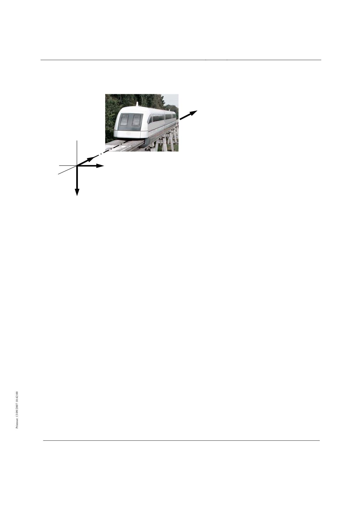
Direction of travel
x - Linear direction
y - Transverse direction
z - Vertical direction
Other coordinate systems are defined in the
subsystems to show special circumstances.
Figure 3: System of coordinates
Title
High-speed Maglev System Design Principles
Complete System
Doc.No.:
50630
Version White
Issue date
15.02.2007
Page 71
paper
Rapid Maglev System
Maglev Technical
Committee
Design Principles
Complete System
Reverse (toward end section 2)
Direction of travel
Forward (toward end section 1)
(vehicle-related)
End section 2
Centre section n+1
Centre section n=1
End section 1
View from above
left side of vehicle
x
right side of vehicle
y
Vehicle and
section centre
with 3, 5 etc.
Gradient
sections
y
Start / End
Line section B
Z
z
Vehicle
hovering
Guideway
Reference hover gap
10
mm
Vehicle and Guideway Coordinates
left side of guideway
ascending kilometre markers
right side of guideway
End
Line section A
In direction of descending kilometre markers
Direction of travel
In direction of ascending kilometre markers
(vehicle-related)
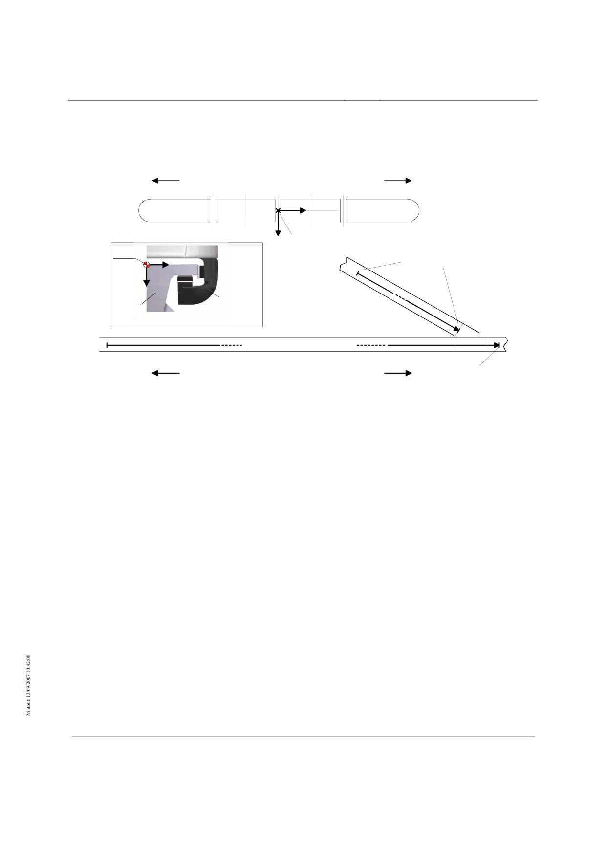
Figure 4: System of coordinates and direction of travel
Title
High-speed Maglev System Design Principles
Complete System
Doc.No.:
50630
Version White
Issue date
15.02.2007
Page 72
paper
Rapid Maglev System
Maglev Technical
Committee
Design Principles
Complete System
U
V
W
t
Î
t
0
Stator pack
3-phase system:
Î
Î/
V
W U
V W U
2
n winding periods
Guideway reference point:
left side of guideway
Direction of thrust
km marker
centreline of the middle position reference strip
right side of guideway
U
V
W
Position ref. strip
U V W
Î/
Î
2
Î
Î/
Lev. magnet ex
citer poles
U
V
W2
U V W
Vehicle reference point:
Centre of levitation magnet in train centre
Reference time
t0
of the 3-phase system
Vehicle reference pointto guideway reference point
Pole position angle 0°
View of guideway from above
V
W U
V W U
Î/
Î
2
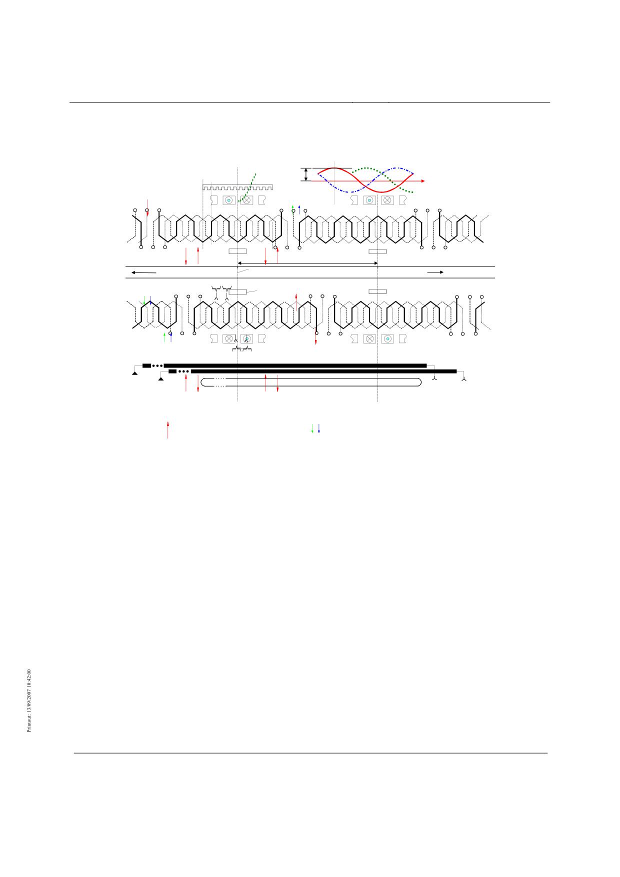
Figure 5: Layout of winding legs, reference position, exciter poles
Title
High-speed Maglev System Design Principles
Complete System
Doc.No.:
50630
Version White
Issue date
15.02.2007
Page 73
paper
Rapid Maglev System
Maglev Technical
Committee
Design Principles
Complete System
MSB vehicle sections for passenger trans-
port
Rettungssystem
Title
High-speed Maglev System Design Principles
Complete System
Doc.No.:
50630
Version White
Issue date
15.02.2007
Page 74
paper
Rapid Maglev System
Maglev Technical
Committee
Design Principles
Complete System
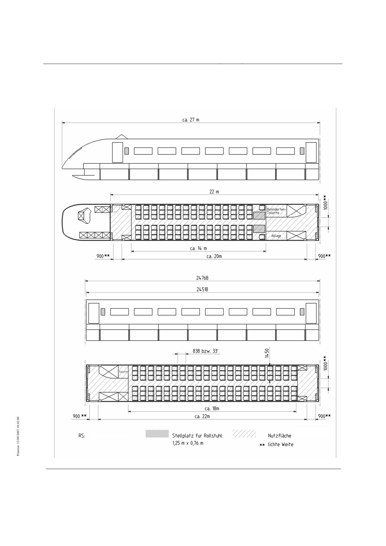
Figure 6: Vehicle sections for passenger transport long-haul (example)
Behindertentoilette
Disabled toilet
Ablage
Storage
bzw.
or
Rettungssystem
Rescue system
Stellplatz für Rollstuhl
Place for wheelchair
Nutzfläche
Useful surface area
lichte Weite
Clear width
Title
High-speed Maglev System Design Principles
Complete System
Doc.No.:
50630
Version White
Issue date
15.02.2007
Page 75
paper
Rapid Maglev System
Maglev Technical
Committee
Design Principles
Complete System
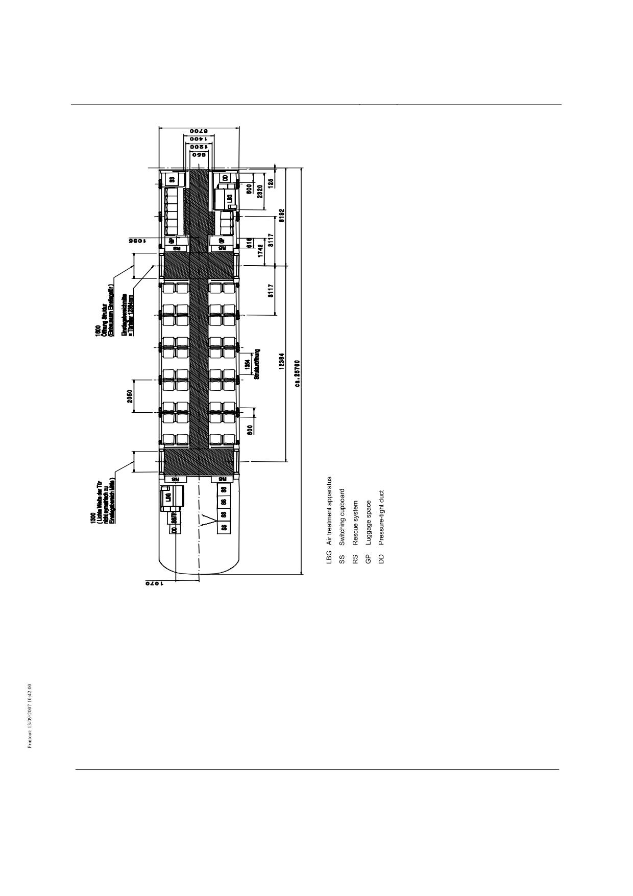
Figure 7: Vehicle end sections for passenger transport airport link (example)
Title
High-speed Maglev System Design Principles
Complete System
Doc.No.:
50630
Version White
Issue date
15.02.2007
Page 76
paper
Rapid Maglev System
Maglev Technical
Committee
Design Principles
Complete System
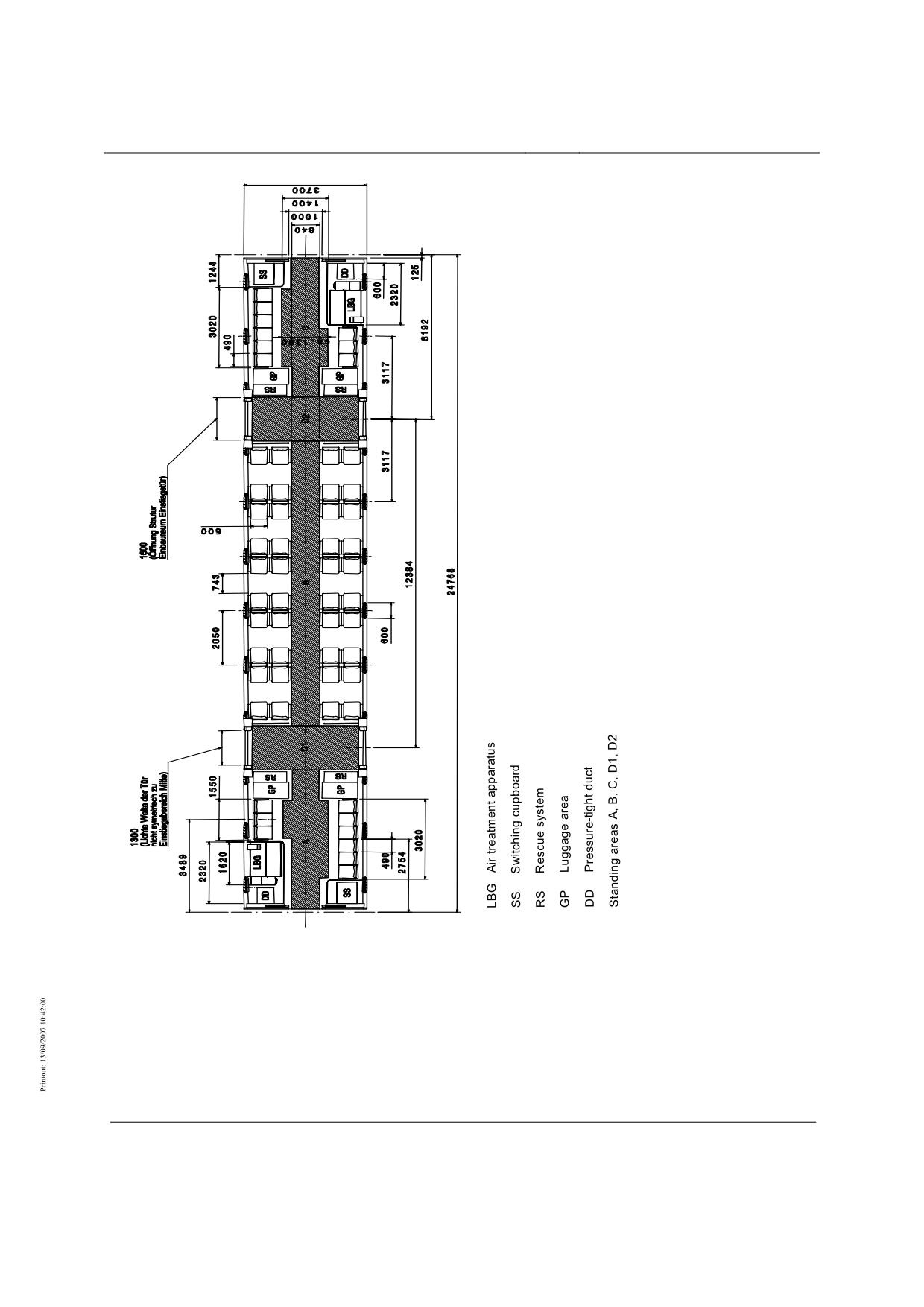
Figure 8: Vehicle centre sections for passenger transport airport link (example)
Title
High-speed Maglev System Design Principles
Complete System
Doc.No.:
50630
Version White
Issue date
15.02.2007
Page 77
paper
Rapid Maglev System
Maglev Technical
Committee
Design Principles
Complete System
Levitation/guide system
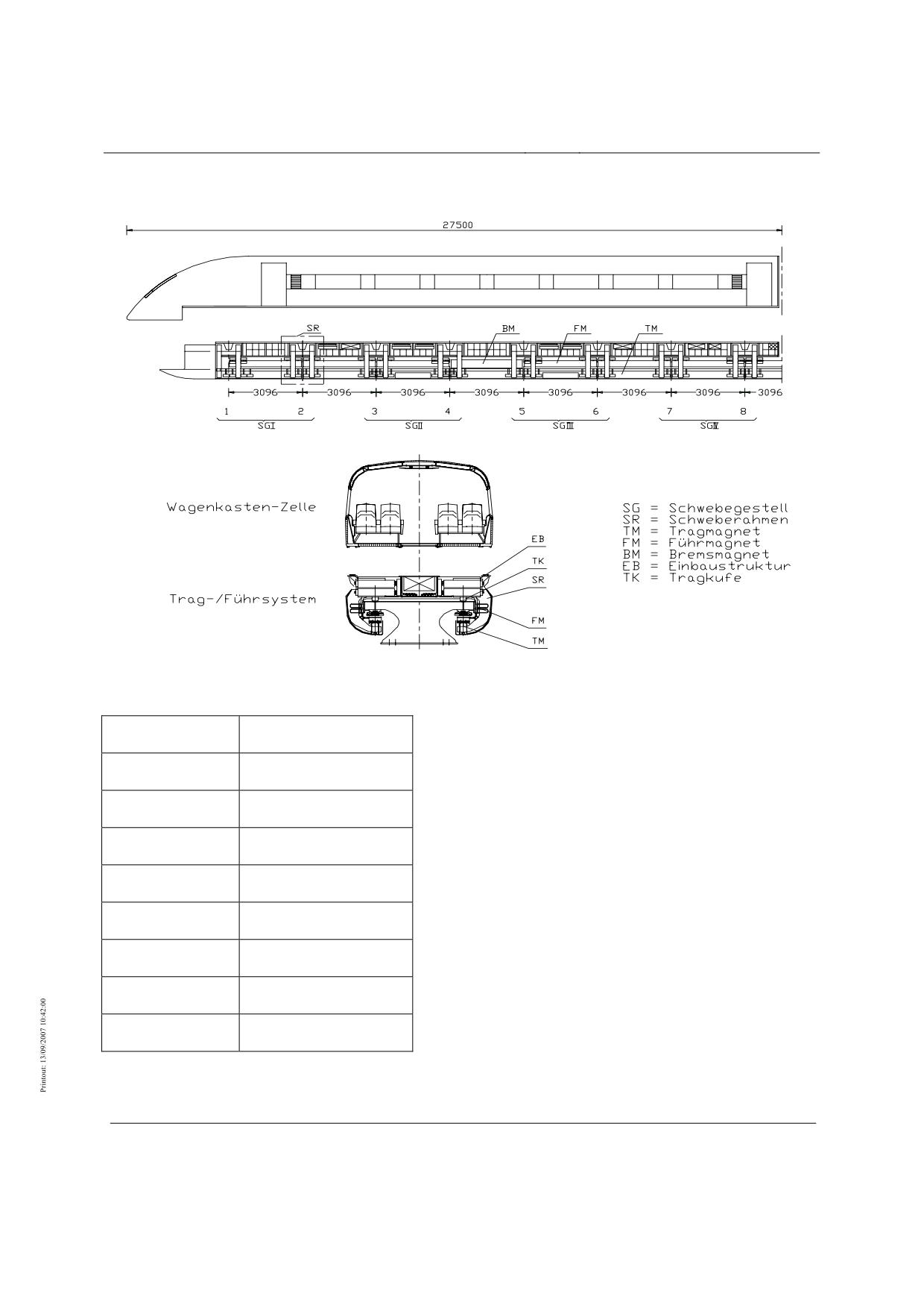
Figure 9: Levitation/guide system (example)
Wagenkasten-Zelle
Body cell
Trag-/Führsystem
Support/guidance system
Schwebegestell
Levitation chassis
Schweberahmen
Levitation frame
Tragmagnet
Support magnet
Führmagnet
Guidance magnet
Bremsmagnet
Braking magnet
Einbaustruktur
Mounting structure
Tragkufe
Support skid
Title
High-speed Maglev System Design Principles
Complete System
Doc.No.:
50630
Version White
Issue date
15.02.2007
Page 78
paper
Rapid Maglev System
Maglev Technical
Committee
Design Principles
Complete System
Braking curve Safe Brake
360 kN
F
Braking force
[kN/section]
250 kN
350
v = 0 km/h
Fx = 360 kN/section (stiction)
max. Dynamic braking force
t
Transitional area:
300
Sliding friction → Stiction
Fx = 250 kN/section
100 ... 200 ms
Sliding in transition to stiction
Fx = 215 kN/section
1
Maximum braking characteristic
250
(basis for designing vehicle and guideway)
Touchdown of skids from slide friction
2
Limiting line for permissible retardation with 1.5 m/s²
Fx = 110 kN/section (equivalent to retardation of 1.5
200
m/s² at max. vehicle weight)
3
Minimum braking force on iced guideway
Minimum braking characteristic
4
(basis of the safe brake profile)
150
1
Force during exceptional effect
2
100
3
4
50
0
0
50
100
150
200
250
300
350
400
450
500
550
Brake magnet resting
Brake magnet
Speed
against lateral guide rail
No contact
[km/h]
Sliding
Braking force from
on support skids
eddy-current brake
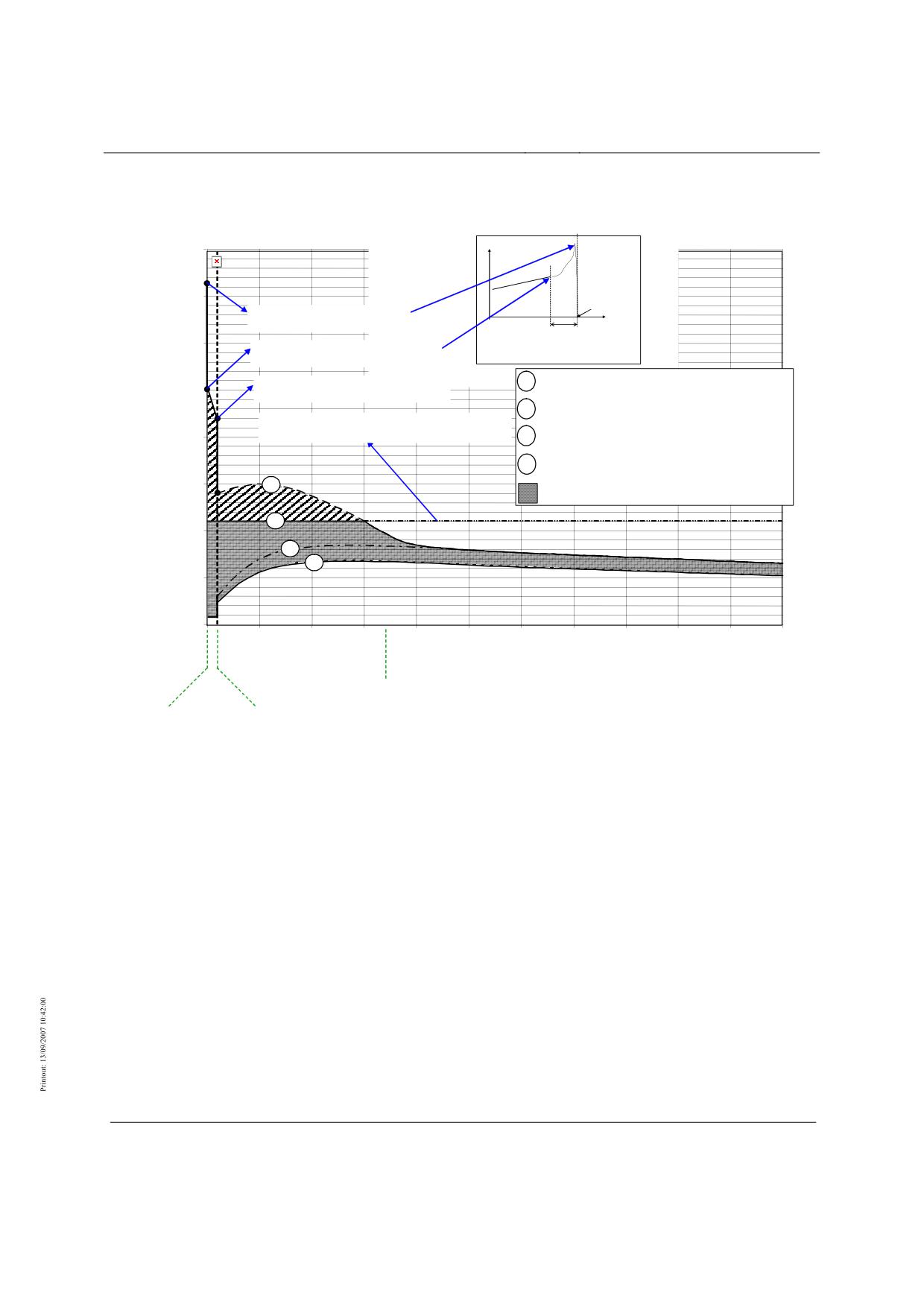
Figure 10: Braking characteristic of safe brake for an MSB vehicle section.
Title
High-speed Maglev System Design Principles
Complete System
Doc.No.:
50630
Version White
Issue date
15.02.2007
Page 79
paper
Rapid Maglev System
Maglev Technical
Committee
Design Principles
Complete System
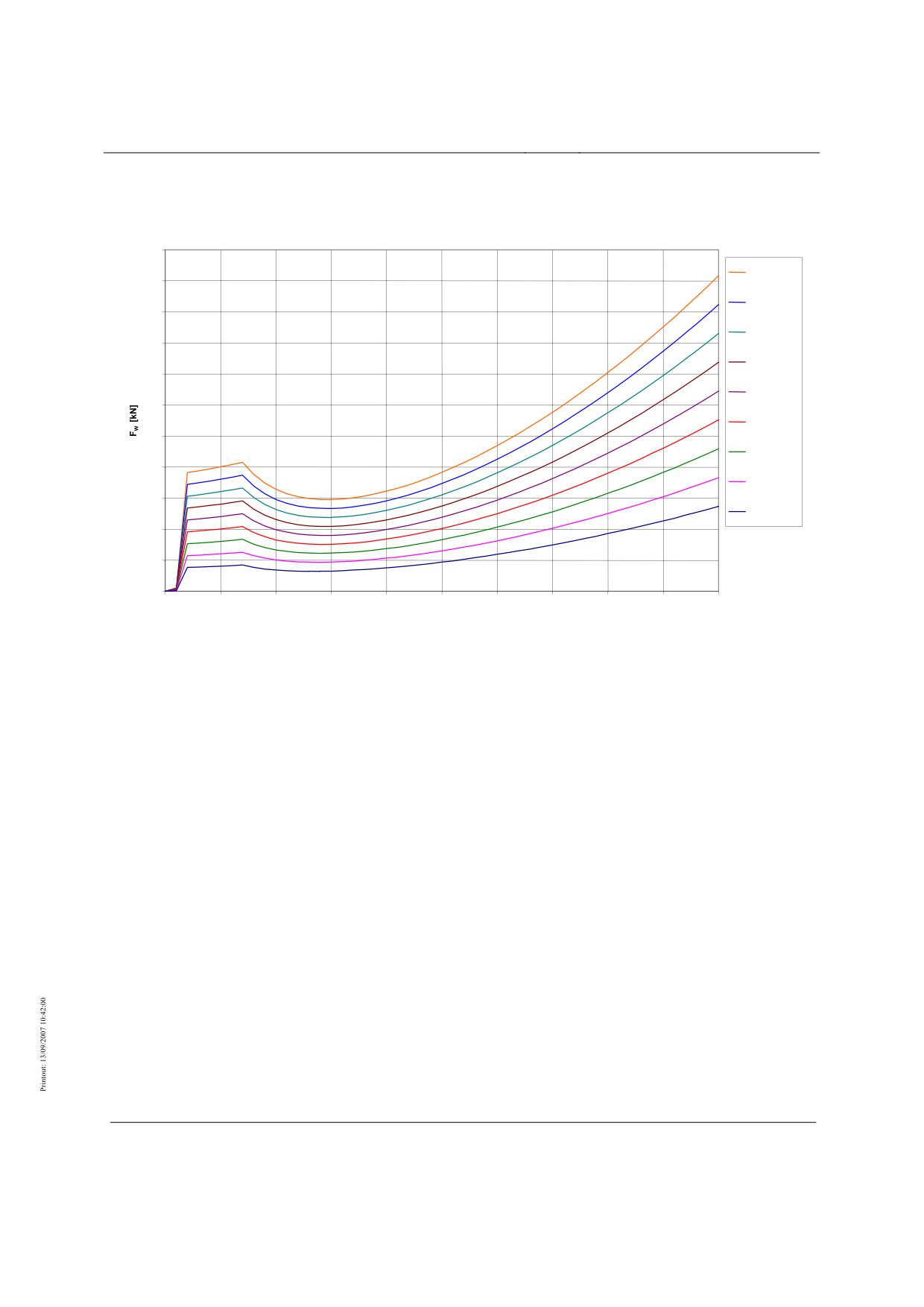
Running resistance
220
10 Sections
200
9 Sections
180
8 Sections
160
7 Sections
140
6 Sections
120
5 Sections
100
4 Sections
80
3 Sections
60
2 Sections
40
20
0
0
50
100
150
200
250
300
350
400
450
500
v [km/h]
For explanation see Chapter 0
Figure 11: Running resistance (airport link - planning status 2006)
Title
High-speed Maglev System Design Principles
Complete System
Doc.No.:
50630
Version White
Issue date
15.02.2007
Page 80
paper
Rapid Maglev System
Maglev Technical
Committee
Design Principles
Complete System
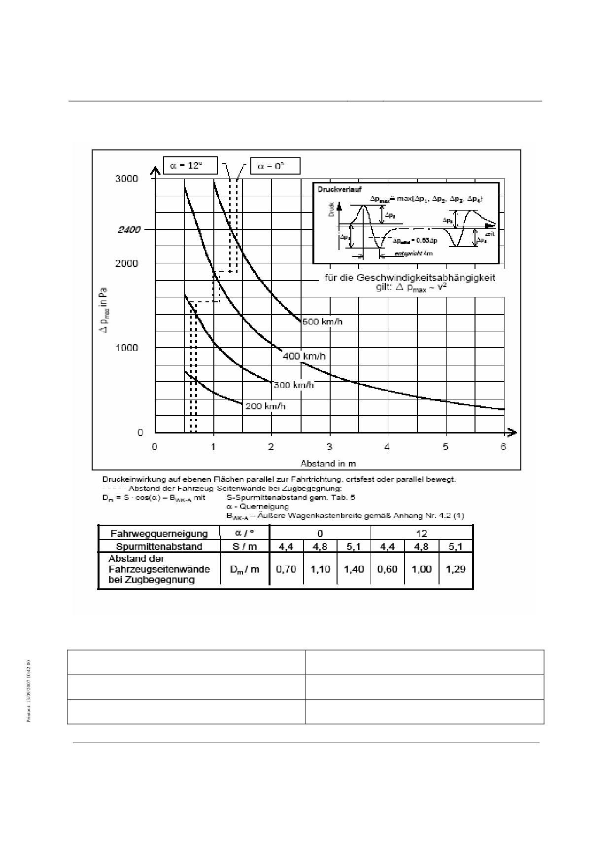
Pressure effect (outside tunnels)
Figure 12: Pressure effect from a passing MSB vehicle (outside tunnels)
(airport link - planning status 2006)
Druckverlauf
Pressure curve
für die Geschwindigkeitsabhängigkeit gilt
the following applies to the velocity function
Abstand in m
Distance in m
Title
High-speed Maglev System Design Principles
Complete System
Doc.No.:
50630
Version White
Issue date
15.02.2007
Page 81
paper
Rapid Maglev System
Maglev Technical
Committee
Design Principles
Complete System
Druckeinwirkung auf ebenen Flächen…
Pressure effect on even surfaces parallel to direction of
travel, fixed or moving in parallel
Abstand der Fahrzeug-Seitenwände…
Distance between vehicle side walls when trains meet
Spurmittenabstand gem. Tab. 5
Track centres according to Table 5
Querneigung
Incline
Äußere Wagenkastenbreite…
External body width according to Annex 4.2 (4)
Fahrwegquerneigung
Guideway incline
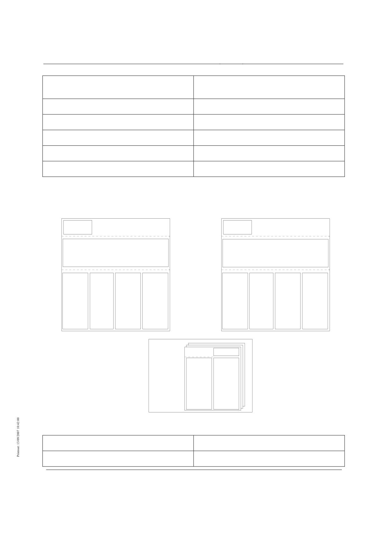
Structure of the energy supply
Unterwerk n
Unterwerk n+1
Steuerung
Steuerung
Energie-
Energie-
versorgung
versorgung
Energieanpassung und -verteilung
Energieanpassung und -verteilung
Hilsenergie-
Blindleistungs-
Externe
Traktions-
Hilfsenergie-
Blindleistungs-
Externe
Traktions-
versorgung
kompensation
Bordenergie-
energie-
versorgung
kompensation
Bordenergie-
energie-
einspeisung
versorgung
einspeisung
versorgung
Streckenseitige Einrichtungen
Steuerung Energie-
versorgung
Hilfsenergie-
Externe
versorgung
Bordenergie-
einspeisung
Unterwerk
Substructure
Steuerung Energie-versorgung
Control of energy supply
Title
High-speed Maglev System Design Principles
Complete System
Doc.No.:
50630
Version White
Issue date
15.02.2007
Page 82
paper

Rapid Maglev System
Maglev Technical
Committee
Design Principles
Complete System
Energieanpassung und -verteilung
Energy adaption and distribution
Hilfsenergieversorgung
Auxiliary energy supply
Blindleistungskompensation
Reactive power compensation
Externe Bordenergie-einspeisung
External onboard energy supply
Traktions-energie-versorgung
Traction energy supply
Streckenseitige Einrichtungen
Track-side equipment
Figure 13: Structure of the energy supply (example)
Structure and functions of the drive
Unterwerk n
Unterwerk n+1
Antriebsregelung/-
Antriebsregelung/-
steuerung
steuerung
Umrichter
Umrichter
Antriebsstrecke m
Streckenkabel
Fahrwegseite
Schaltstelle
Statorab-
schnitt
Figure 14: Structure of the drive (example)
Unterwerk
Substructure
Antriebsregelung/-steuerung
Propulsion system regulation/control
Umrichter
Converter
Antriebsstrecke
Drive section
Title
High-speed Maglev System Design Principles
Complete System
Doc.No.:
50630
Version White
Issue date
15.02.2007
Page 83
paper
Rapid Maglev System
Maglev Technical
Committee
Design Principles
Complete System
Streckenkabel
Section cable
Fahrwegseite
Guideway side
Statorabschnitt
Stator section
Schaltstelle
Switching point
Betriebsleittechnik
Fahrzeug
Antriebsvorgaben
Antriebsvorgaben
Ortsinformation
über Datenübertragung der BLT
Antriebssteuerung
Abschaltbefehl
Betriebsart
Betriebsart
Betriebsart
Streckensteuerung
Fahrzeugführung
Fahrzeugort,
-geschwindigkeit
aktiver Statorabschnitt
Sollvorgabe Statorstrom
Stromregelung
Betriebsart
Stellgrößen
Schaltbefehle
Istwerte Motor
Umrichterregelung / -
steuerung
Steuerbefehle
Istwerte
Antriebsstrecke
Umrichter
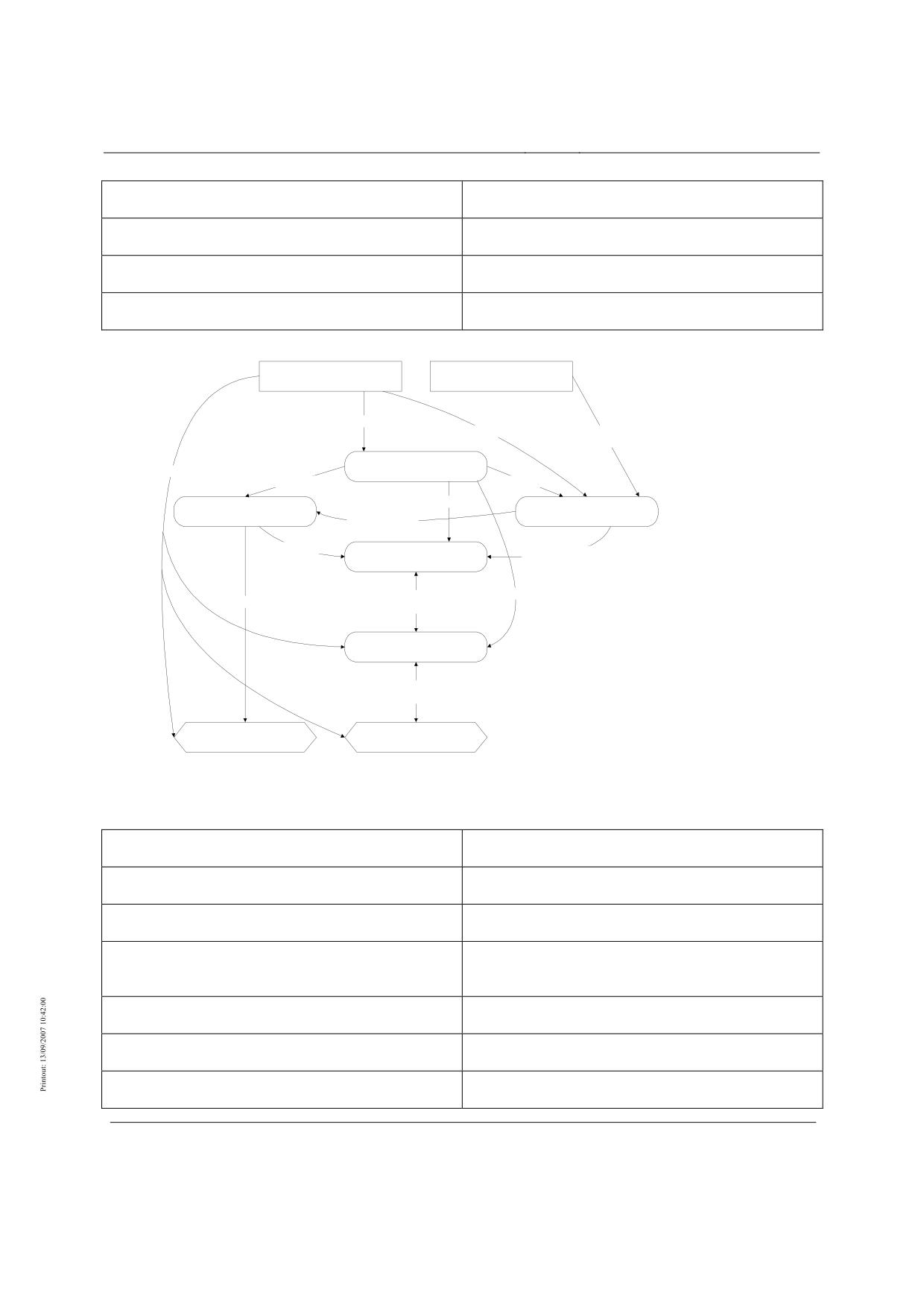
Drive functions are shown in oval boxes and external components in rectangular boxes.
Figure 15: Functions of the drive
Betriebsleittechnik
Operational control system (BLT)
Fahrzeug
Vehicle
Antriebsvorgaben
Propulsion system settings
Ortsinformation über Datenübertragung der BLT
Location information regarding data transmission from
BLT
Abschaltbefehl
Shutdown command
Betriebsart
Type of operation
Antriebssteuerung
Propulsion system control
Title
High-speed Maglev System Design Principles
Complete System
Doc.No.:
50630
Version White
Issue date
15.02.2007
Page 84
paper
Rapid Maglev System
Maglev Technical
Committee
Design Principles
Complete System
Streckensteuerung
Section control
Fahrzeugart, -geschwindigkeit
Vehicle type, speed
Fahrzeugführung
Vehicle guidance
aktiver Statorabschnitt
active stator section
Stromregelung
power control
Sollvorgabe Statorstrom
Desired settings for stator power
Stellgrößen Istwerte Motor
Variables for actual values for motor
Schaltbefehle
Switching commands
Umrichterregelung/-steuerung
Convertor regulation/control
Steuerbefehle Istwerte
Control commands actual values
Antriebsstrecke
Propulsion system section
Umrichter
Covnertor
Structure and functions of the operation
control system
Fahrdienst -
leitung
Fahrweg,
BLT
Fahrzeug
Stationen
Antrieb
Instandhaltung
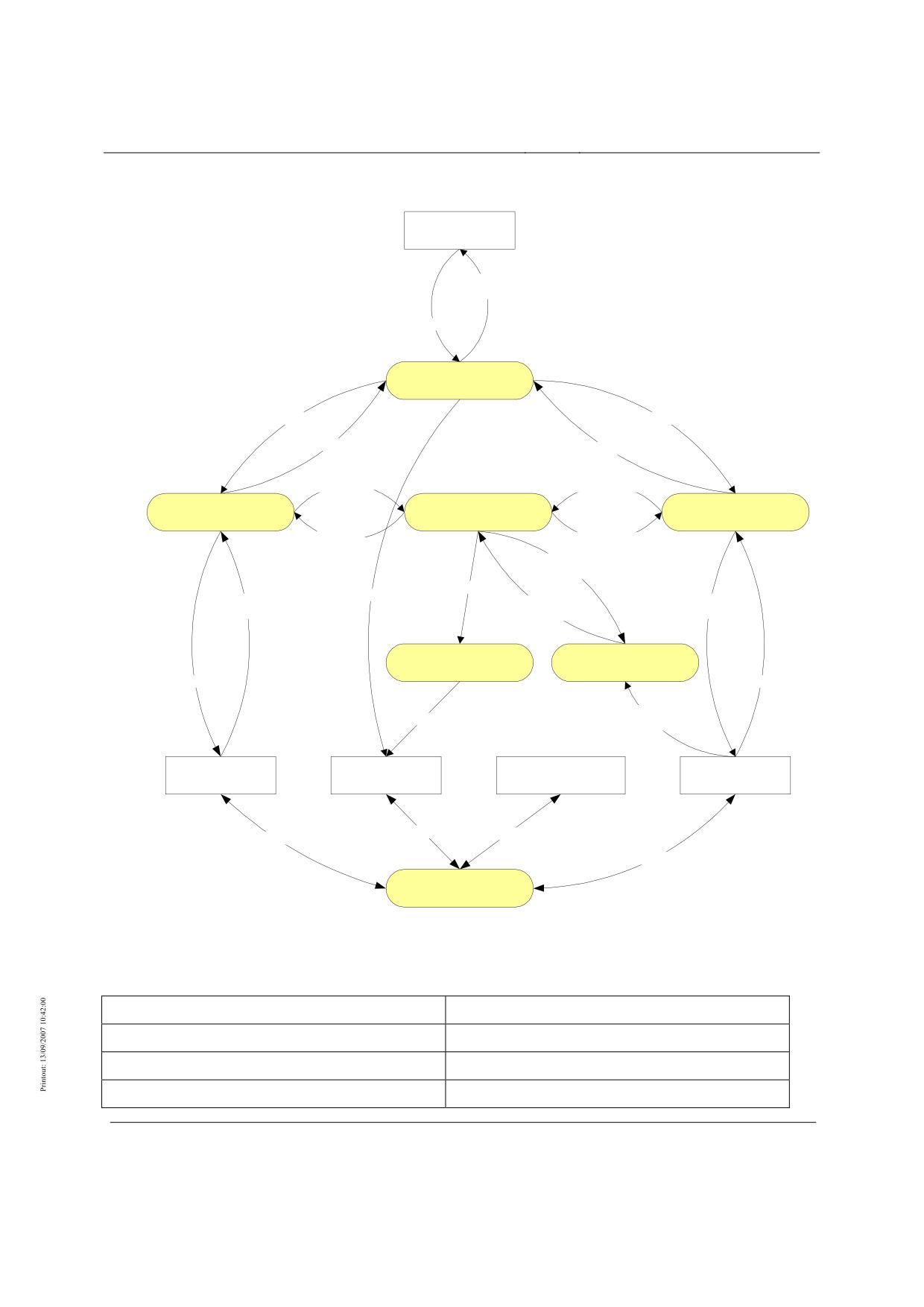
Figure 16: Placement and interfaces of the OCS
Title
High-speed Maglev System Design Principles
Complete System
Doc.No.:
50630
Version White
Issue date
15.02.2007
Page 85
paper
Rapid Maglev System
Maglev Technical
Committee
Design Principles
Complete System
Fahrdienstleitung
Traffic controller
Fahrweg, Stationen
Guideway, stations
Fahrzeug
Vehicle
Antrieb
Propulsion system
Instandhaltung
Maintenance
Title
High-speed Maglev System Design Principles
Complete System
Doc.No.:
50630
Version White
Issue date
15.02.2007
Page 86
paper
Rapid Maglev System
Maglev Technical
Committee
Design Principles
Complete System
Fahrdienstleitung
Meldungen,
Anzeigen
Fahrtvorgaben
Fahrablaufsteuerung
Fahrwegparameter
Fahrzeugparameter
Fahrweggdaten
Fahrzeugdaten
Fahrwegdaten
Fahrzeugdaten
Fahrprofil -
Fahrwegsicherung
Fahrzeugsicherung
überwachung
Fahrzeug-
Profilverletzung
bewegung
Ortungs-
parameter
Profilverletzung
Antriebsvorgaben
Lageinformation,
Ort,
Stellbefehle,
Meldungen
Geschwindigkeit
Ausgaben
Antriebsabschaltung
Sichere Ortung
Stellbefehle
Eingaben
Ort,
Abschaltbefehl
Geschindigkeit
Fahrweg,
Antrieb
Instandhaltung
Fahrzeug
Stationen
Daten
Daten
Daten
Daten
Datenübertragung
OCS functions are shown in oval boxes and external components in rectangular boxes.
Figure 17: OCS functions and data flows
Fahrdienstleitung
Traffic controller
Meldungen, anzeigen
Messages, displays
Fahrtvorgaben
Trip settings
Fahrablaufsteurerung
Trip progress control
Title
High-speed Maglev System Design Principles
Complete System
Doc.No.:
50630
Version White
Issue date
15.02.2007
Page 87
paper
Rapid Maglev System
Maglev Technical
Committee
Design Principles
Complete System
Fahrwegparameter
Guideway parameters
Fahrzeugparameter
Vehicle parameters
Fahrwegdaten
Guideway data
Fahrzeugdaten
Vehicle data
Fahrwegsicherung
Guideway protection
Fahrprofilüberwachung
Driving profile monitoring
Fahrzeugsicherung
Vehicle protection
Fahrzeugbewegung
Vehicle movement
Profilverletzung
Profile violation
Ortungsparameter
Location parameters
Lageinformationen, Meldungen
Position information, messages
Antriebsvorgaben
Propulsion system settings
Ort, Geschwindigkeit
Location, speed
Stellbefehle, Ausgaben
Actuator commands and output
Antriebsabschaltung
Propulsion system shutdown
Sichere Ortung
Safe location
Stellbefehle
Actuator commands
Eingaben
Inputs
Abschaltbefehl
Shutdown command
Ort, Geschwindigkeit
Location, speed
Fahrweg, Stationen
Guideway, stations
Antrieb
Propulsion system
Instandhaltung
Maintenance
Fahrzeug
Vehicle
Daten
Data
Datenübertragung
Data transmission
Title
High-speed Maglev System Design Principles
Complete System
Doc.No.:
50630
Version White
Issue date
15.02.2007
Page 88
paper
Rapid Maglev System
Maglev Technical
Committee
Design Principles
Complete System
Structure of the positioning
Einrichtungen am Fahrzeug
Anzeige
Betriebsleittechnik
Antrieb
Sichere Ortung
BLT-Funktionen
Steuerungstechnisch relev ante
Ortung
Datenübertragung
Antriebsregelung
Mobil-Ortsf est
Referenzorte
Relativ ort
Einrichtungen am Fahrweg
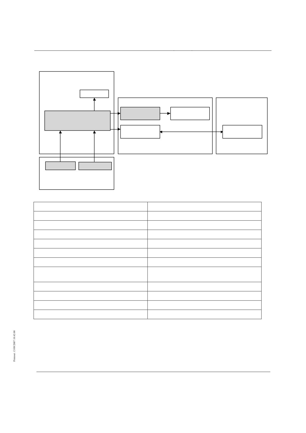
Figure 18: Structure of the positioning (example)
Einrichtungen am Fahrzeug
Equipment on vehicle
Anzeige
Display
Betriebsleittechnik
Operational control system (BLT)
Antrieb
Propulsion system
Sichere Ortung
Safe location
BLT-Funktionen
BLT functions
Steuerungstechnisch relevante Ortung
Location that is relevant to the controls
Datenübertragung Mobil-Ortsfest
Transmission of data between mobile and fixed
locations
Antriebsregelung
Regulation of propulsion system
Referenzorte
Reference locations
Relativort
Relative location
Einrichtungen am Fahrweg
Equipment on guideway
Title
High-speed Maglev System Design Principles
Complete System
Doc.No.:
50630
Version White
Issue date
15.02.2007
Page 89
paper
Rapid Maglev System
Maglev Technical
Committee
Design Principles
Complete System
Elevated guideway
Clearance gauge
Boundary line for the
kinematic space requirement
of the vehicle
e.g. 24768
Superstruct
Substructur
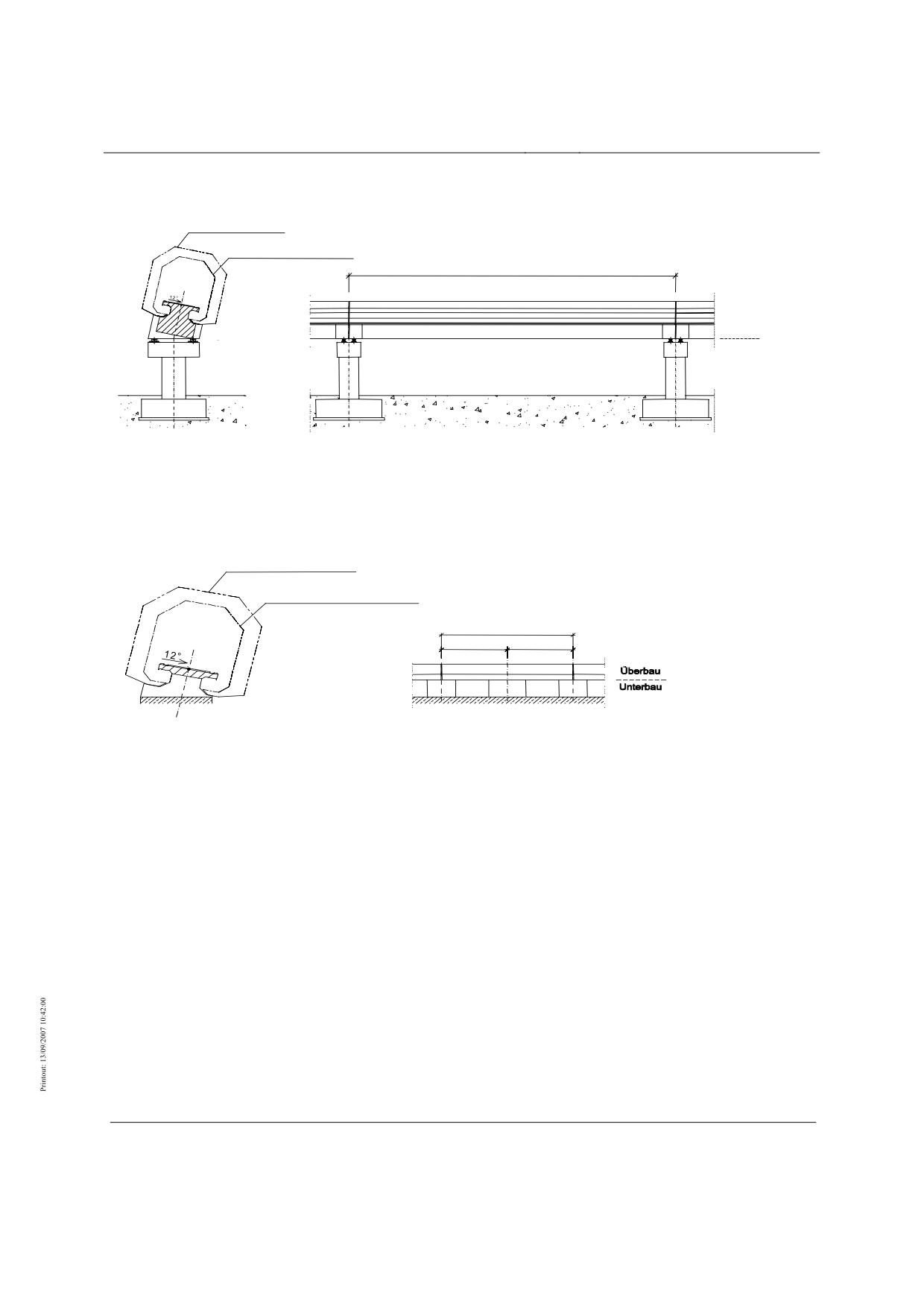
Figure 19: Elevated guideway (example)
At-grade guideway
Clearance gauge
Boundary lie for the
kinem atic space requirem ent
of the vehicle
6192
3096
3096
Figure 20: At-grade guideway (example)
Title
High-speed Maglev System Design Principles
Complete System
Doc.No.:
50630
Version White
Issue date
15.02.2007
Page 90
paper
Rapid Maglev System
Maglev Technical
Committee
Design Principles
Complete System
Beam dimension
Component length (L)
System axis
System axis
Stator axis (outside of bend)
System length of
guideway beam
(L
)
Sys
3D curve
Stator axis (inside of bend)
R
H
Gap at beam joint
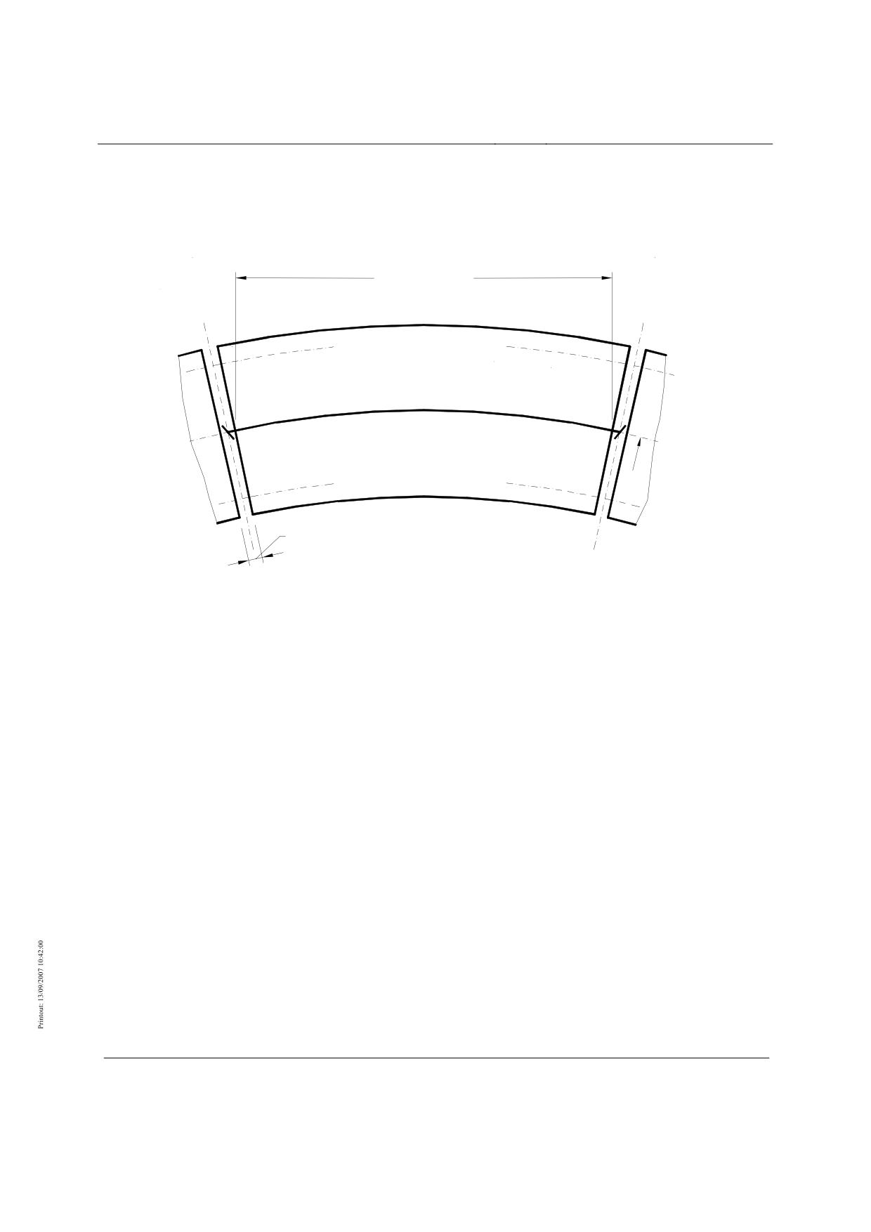
Figure 21: Beam dimension - Relationship between component length and system length
Title
High-speed Maglev System Design Principles
Complete System
Doc.No.:
50630
Version White
Issue date
15.02.2007
Page 91
paper
Rapid Maglev System
Maglev Technical
Committee
Design Principles
Complete System
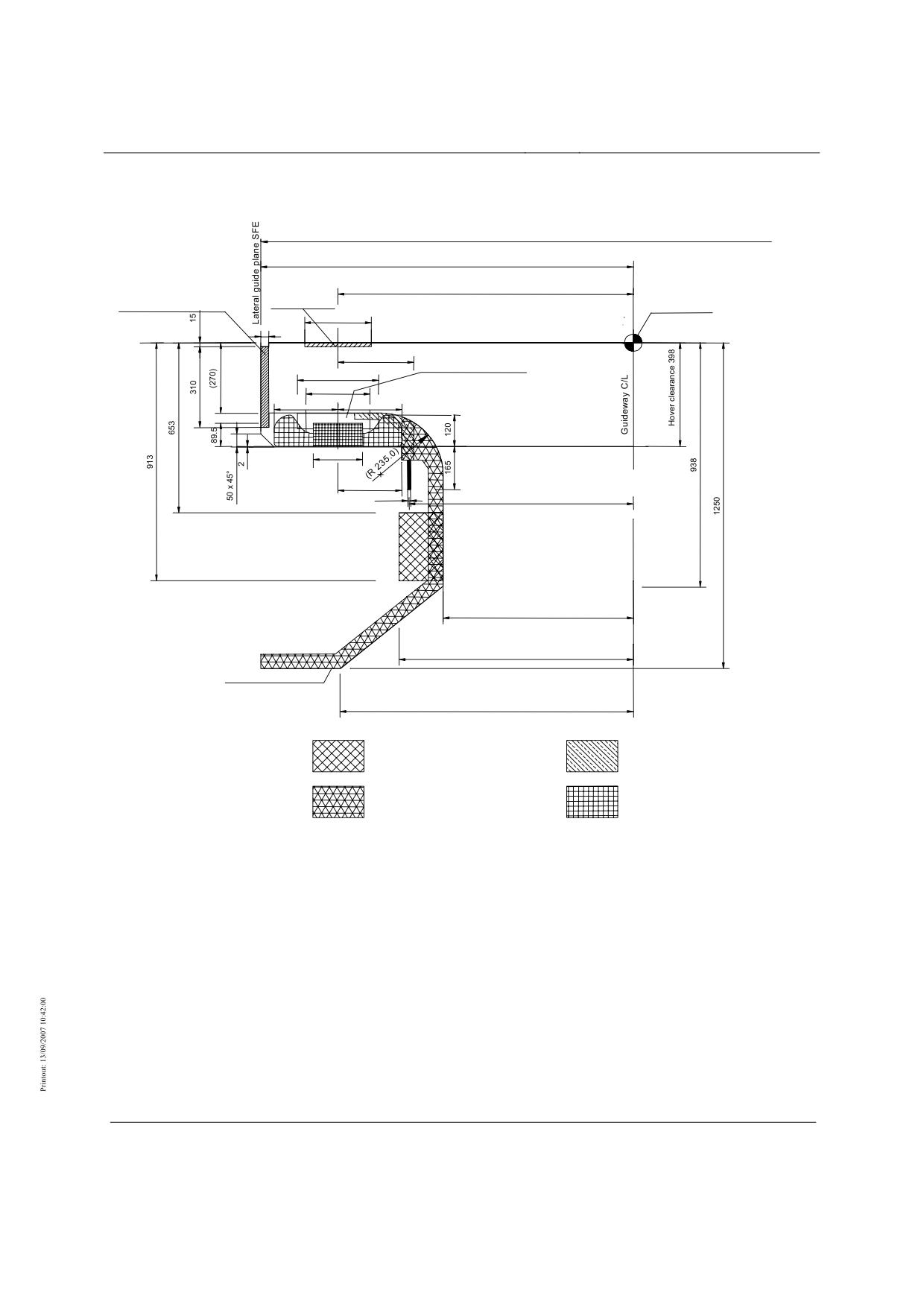
Guideway equipment and functional planes
Gauge 2800
1400
1110
Lateral guide rail SFS
Slide rail GL
3D curve
250
min. 30
Slide plane GE
285
Stator pack mounting
305
240
max. 240
max. 240
Stator plane SE
185
240
10
842.5
715
885
Guideway boundary
1102
Space for external
Space for
onboard energy supply
positioning modules
Space for
Space for
LSW incoming and outgoing cable
motor winding
(
) Figures in brackets are design-specific
Figure 22: Functional elements, functional planes and installation spaces on the guideway, dimensions (nominal)
Title
High-speed Maglev System Design Principles
Complete System
Doc.No.:
50630
Version White
Issue date
15.02.2007
Page 92
paper
Rapid Maglev System
Maglev Technical
Committee
Design Principles
Complete System
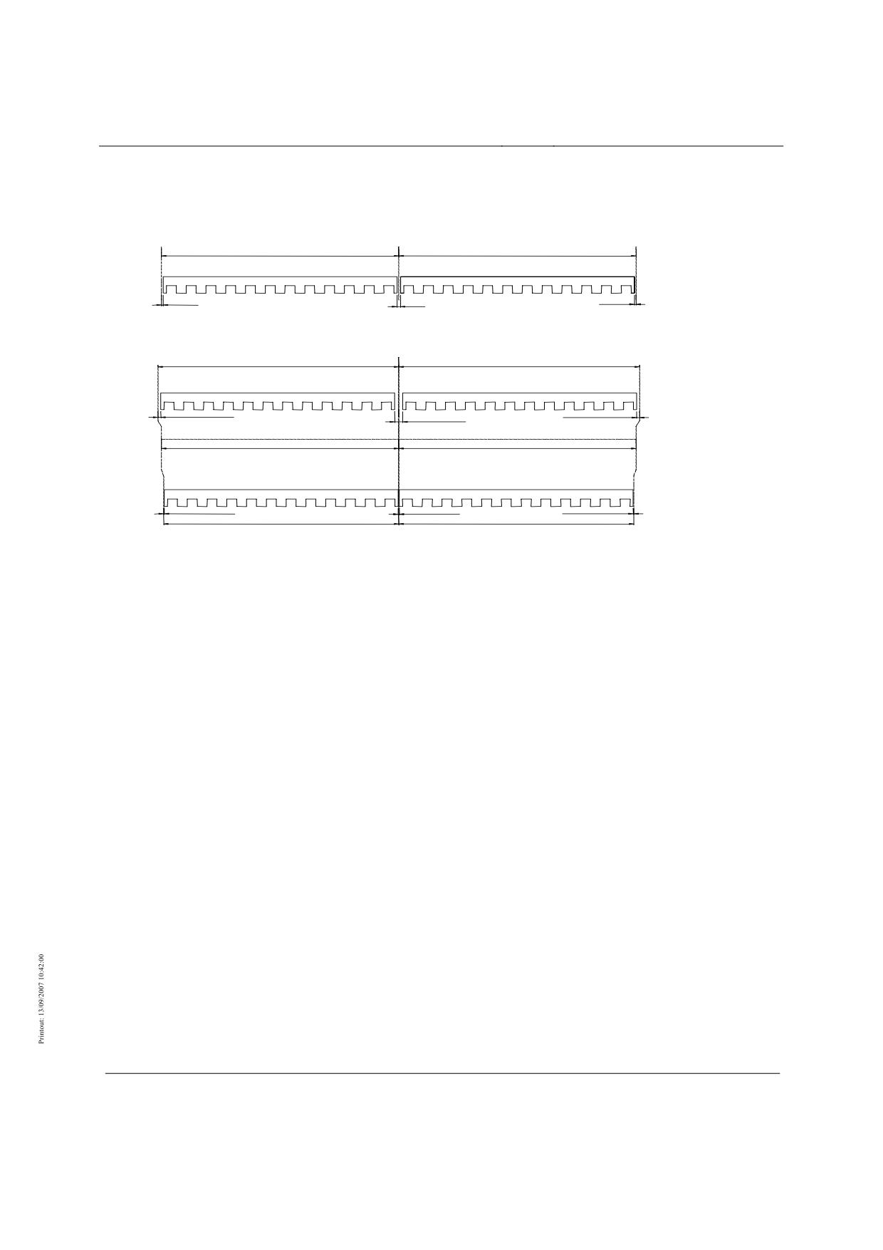
Stator pack arrangement
Stator pack arrangement on straight guideway
1032 (System dimension)
1032 (System dimension)
1/2 gap
gap
1/2 gap
Stator pack arrangement on horizontally curved guideway
1032 (System dimension) + differenc xe for outside bend
1032 (System dim ension) + difference for outside bend
(bend outside)
1/2 gap bend outside
1/2 gap bend outside
Gap bend outside
3D curve
1032 (System dimension)
1032 (System dimension)
(bend inside)
1/2 gap bend inside
Gap bend inside
1/2 gap bend inside
1032 (System dimension) - difference for inside bend
1032 (System dimension) - difference for inside bend
The lengths of the individual stator pack types must be defined project-specifically.
Figure 23: Stator pack arrangement (example)
Title
High-speed Maglev System Design Principles
Complete System
Doc.No.:
50630
Version White
Issue date
15.02.2007
Page 93
paper
Rapid Maglev System
Maglev Technical
Committee
Design Principles
Complete System
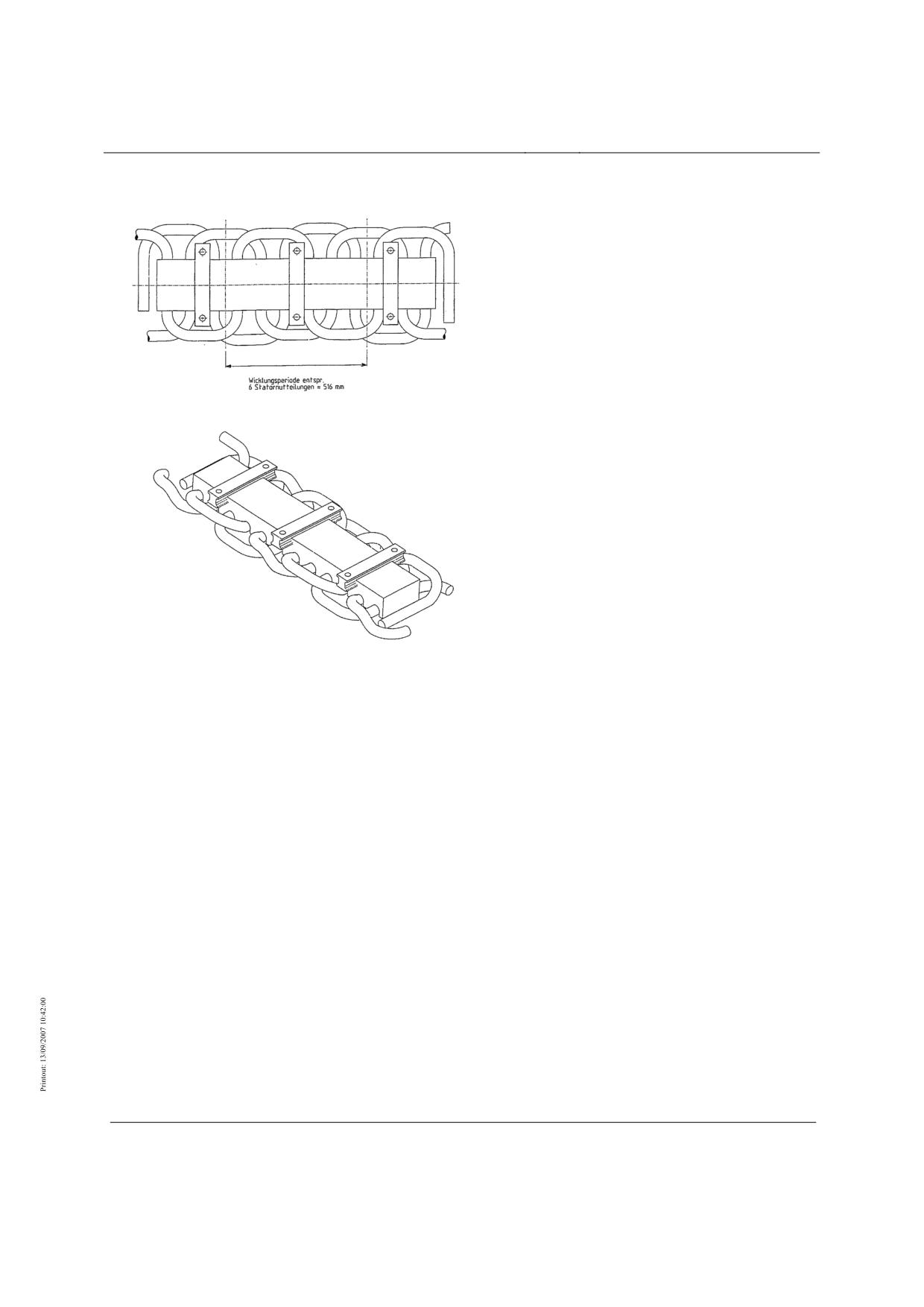
Long-stator winding
Figure 24: Long-stator winding (example)
Wicklungsperiode entspr. 6 Statornutteilungen = Winding period corresponding to 6 stator slot pitches
Title
High-speed Maglev System Design Principles
Complete System
Doc.No.:
50630
Version White
Issue date
15.02.2007
Page 94
paper
Rapid Maglev System
Maglev Technical
Committee
Design Principles
Complete System
Track-switching devices
Title
High-speed Maglev System Design Principles
Complete System
Doc.No.:
50630
Version White
Issue date
15.02.2007
Page 95
paper
Rapid Maglev System
Maglev Technical
Committee
Design Principles
Complete System
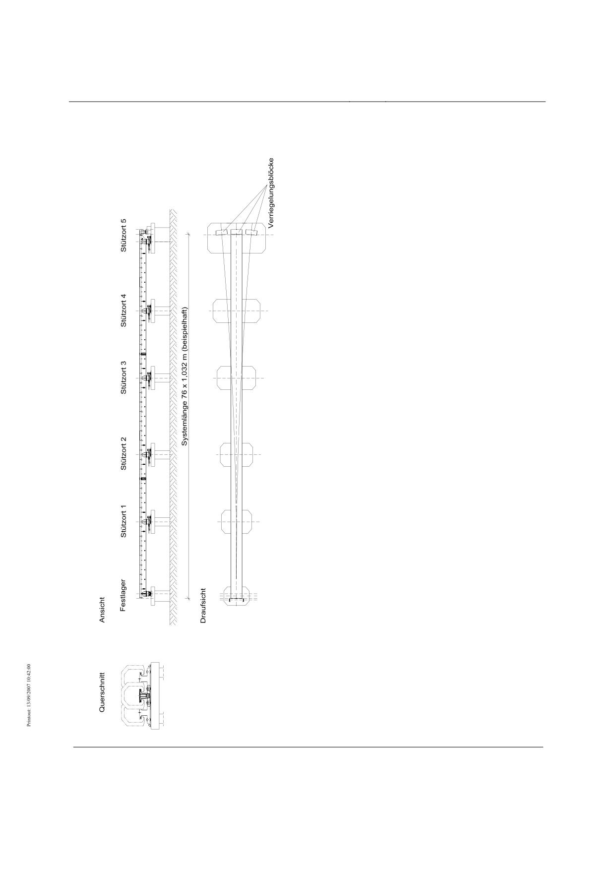
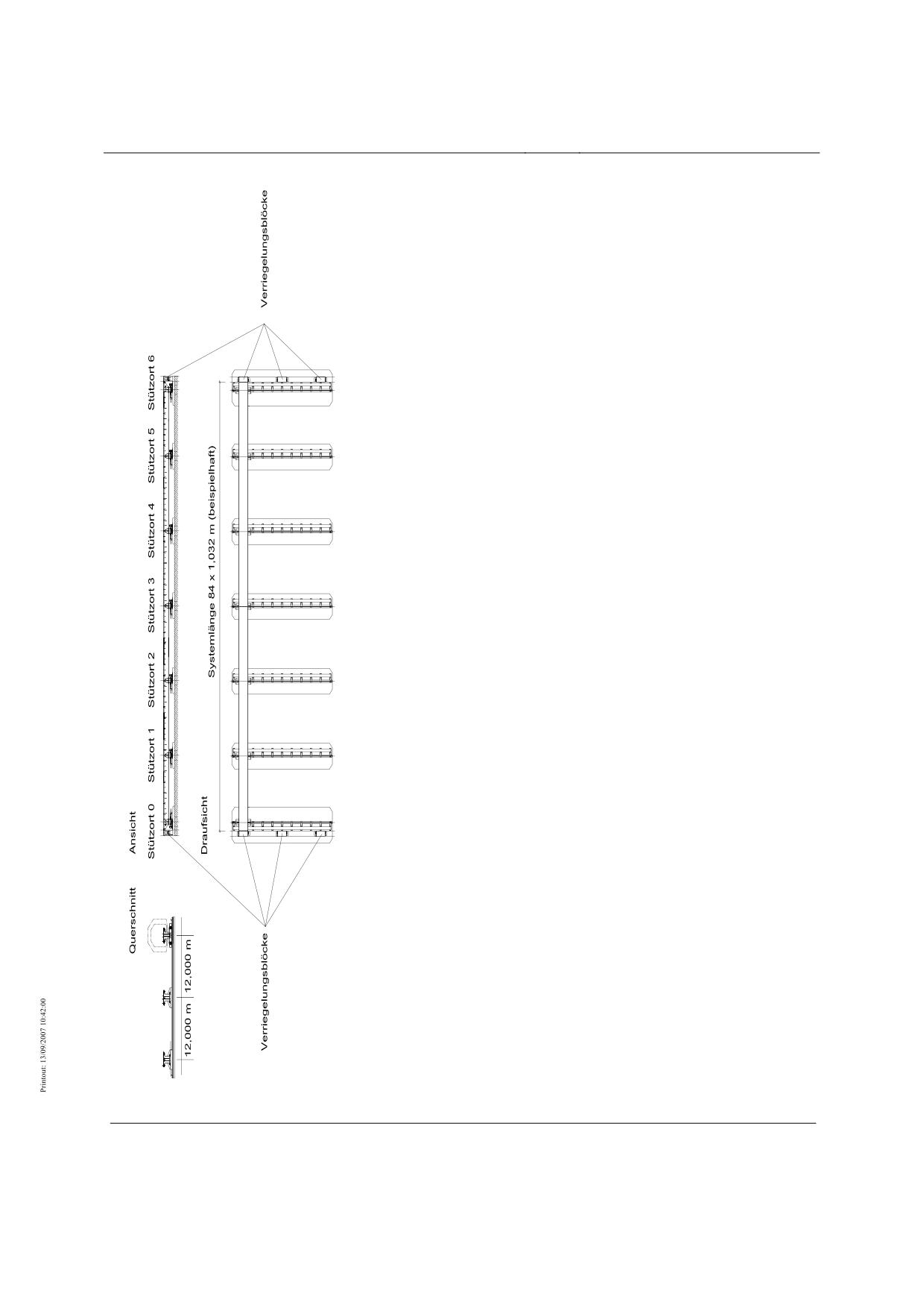
Figure 25: Point (example)
Querschnitt
Cross-section
Ansicht
Front view
Festlager
Fixed bearing
Stützort
Support point
Systemlänge (beispielhaft)
System length (example)
Draufsicht
Plan view
Verriegelungsblöcke
Locking blocks
Title
High-speed Maglev System Design Principles
Complete System
Doc.No.:
50630
Version White
Issue date
15.02.2007
Page 96
paper
Rapid Maglev System
Maglev Technical
Committee
Design Principles
Complete System
Title
High-speed Maglev System Design Principles
Complete System
Doc.No.:
50630
Version White
Issue date
15.02.2007
Page 97
paper
Rapid Maglev System
Maglev Technical
Committee
Design Principles
Complete System
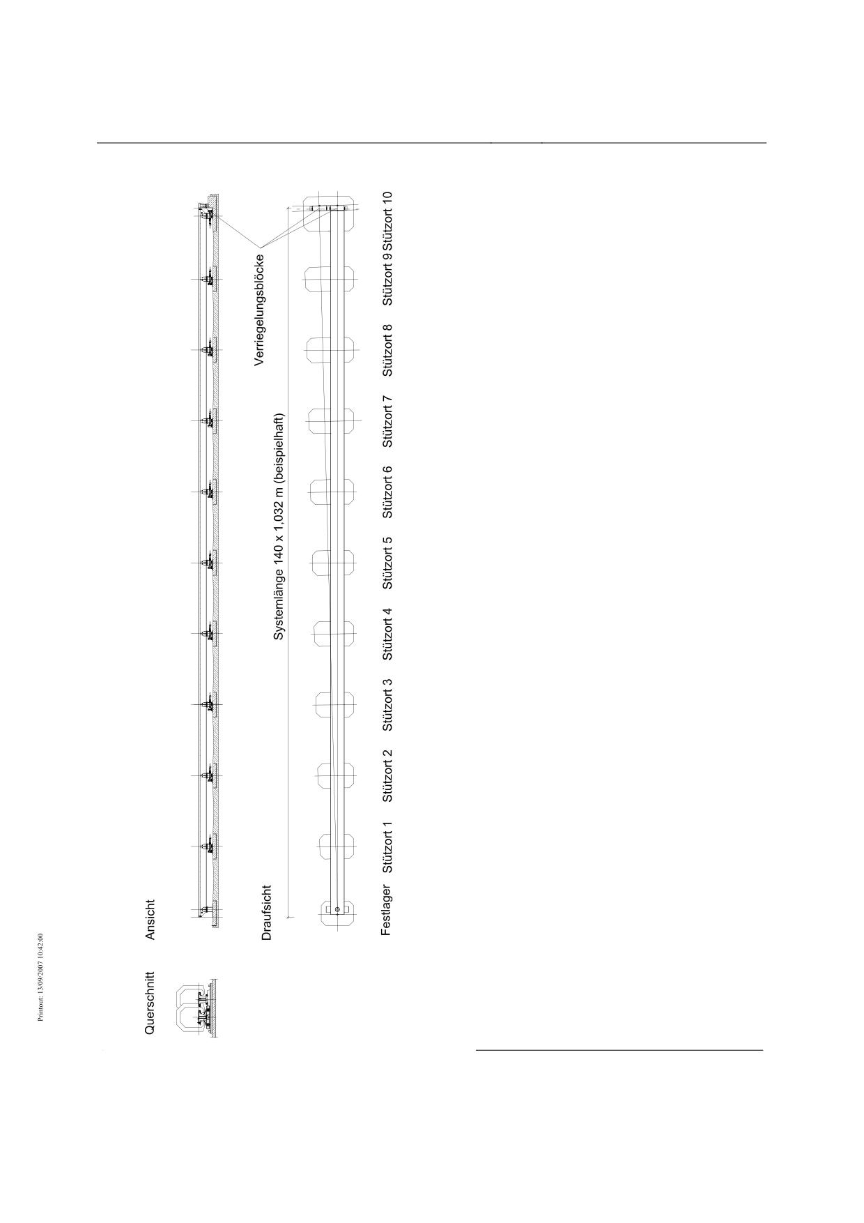
Figure 26: Traverser (example)
Querschnitt
Cross-section
Ansicht
Front view
Stützort
Support point
Systemlänge (beispielhaft)
System length (example)
Draufsicht
Plan view
Verriegelungsblöcke
Locking blocks
Title
High-speed Maglev System Design Principles
Complete System
Doc.No.:
50630
Version White
Issue date
15.02.2007
Page 98
paper
Rapid Maglev System
Maglev Technical
Committee
Design Principles
Complete System
Title
High-speed Maglev System Design Principles
Complete System
Doc.No.:
50630
Version White
Issue date
15.02.2007
Page 99
paper
Rapid Maglev System
Maglev Technical
Committee
Design Principles
Complete System
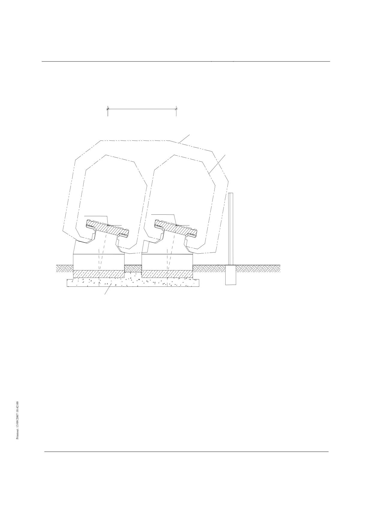
Figure 27: Turntable (example)
Querschnitt
Cross-section
Ansicht
Front view
Festlager
Fixed bearing
Stützort
Support point
Systemlänge (beispielhaft)
System length (example)
Draufsicht
Plan view
Verriegelungsblöcke
Locking blocks
Title
High-speed Maglev System Design Principles
Complete System
Doc.No.:
50630
Version White
Issue date
15.02.2007
Page 100
paper
Rapid Maglev System
Maglev Technical
Committee
Design Principles
Complete System
Protective structures
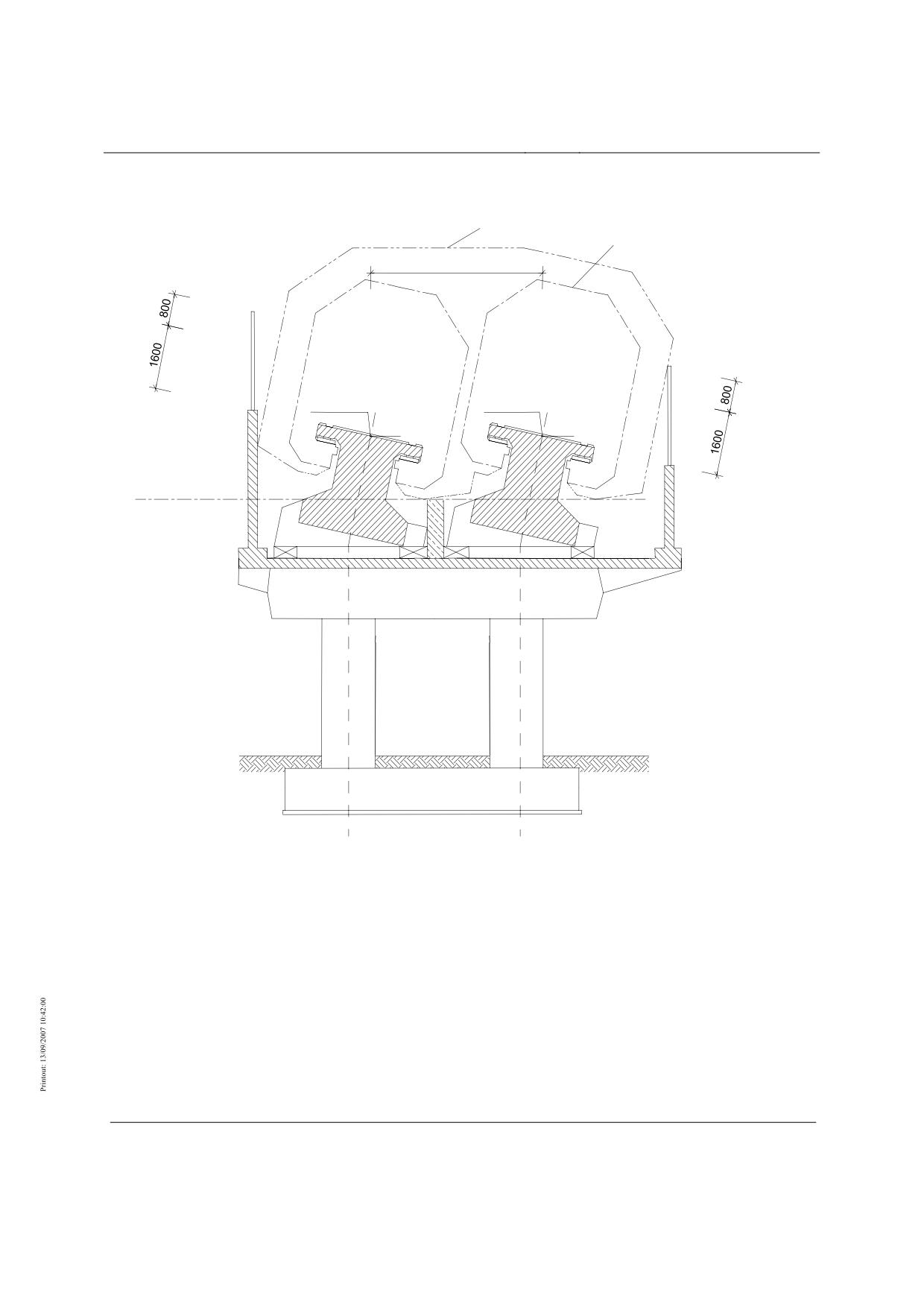
s
Clearance gauge
Boundary line for the
kinematic space requirement
of the vehicle
3D curve
3D curve
Possible site of noise barrier or
possible site of fence on the
12°
12°
clearance boundary
Grade
Frost protection layer
Figure 28: Noise barrier and fence on at-grade guideway (example)
Title
High-speed Maglev System Design Principles
Complete System
Doc.No.:
50630
Version White
Issue date
15.02.2007
Page 101
paper
Rapid Maglev System
Maglev Technical
Committee
Design Principles
Complete System
Clearance gauge
Boundary line for the
kinematic space requirement
of the vehicle
s
3D curve
3D curve
12°
12°
Walkway
level
Figure 29: Noise barrier on elevated guideway (example)
Title
High-speed Maglev System Design Principles
Complete System
Doc.No.:
50630
Version White
Issue date
15.02.2007
Page 102
paper
Rapid Maglev System
Maglev Technical
Committee
Design Principles
Complete System
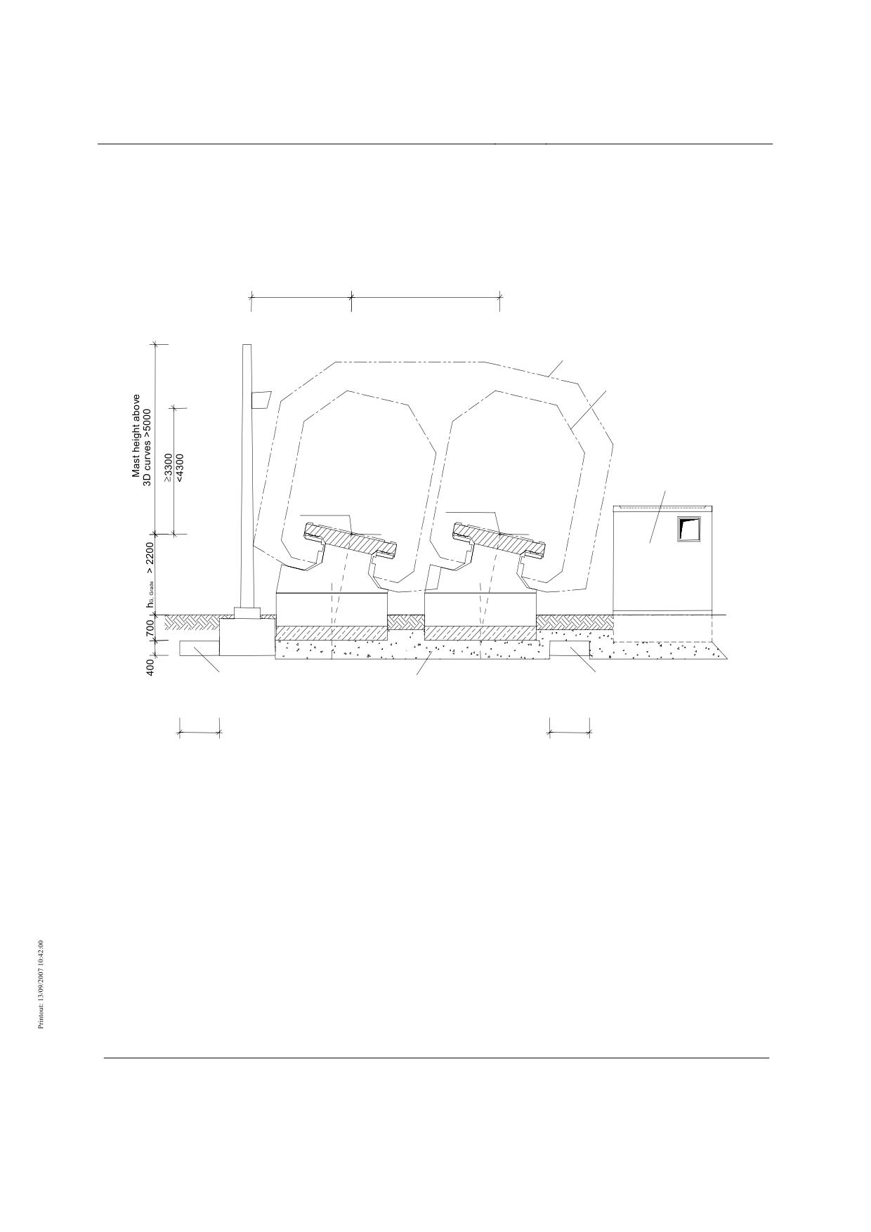
Route peripherals
Radio mast
minimum clearance *
3254 (12°)
(3150 2 %)
s
Clearance gauge
Boundary line for the
kinematic space requirement
of the vehicle
possible
site of the
switch point /
transformer station /
emergency power /
BE station
3D curve
3D curve
12°
12°
Space for cables
Space for cables für
Frost protection layer
1200
1200
* except special cases
hG, Grade - Gradient height above grade after completion
Figure 30: Route peripherals with at-grade guideway (example)
Title
High-speed Maglev System Design Principles
Complete System
Doc.No.:
50630
Version White
Issue date
15.02.2007
Page 103
paper
Rapid Maglev System
Maglev Technical
Committee
Design Principles
Complete System
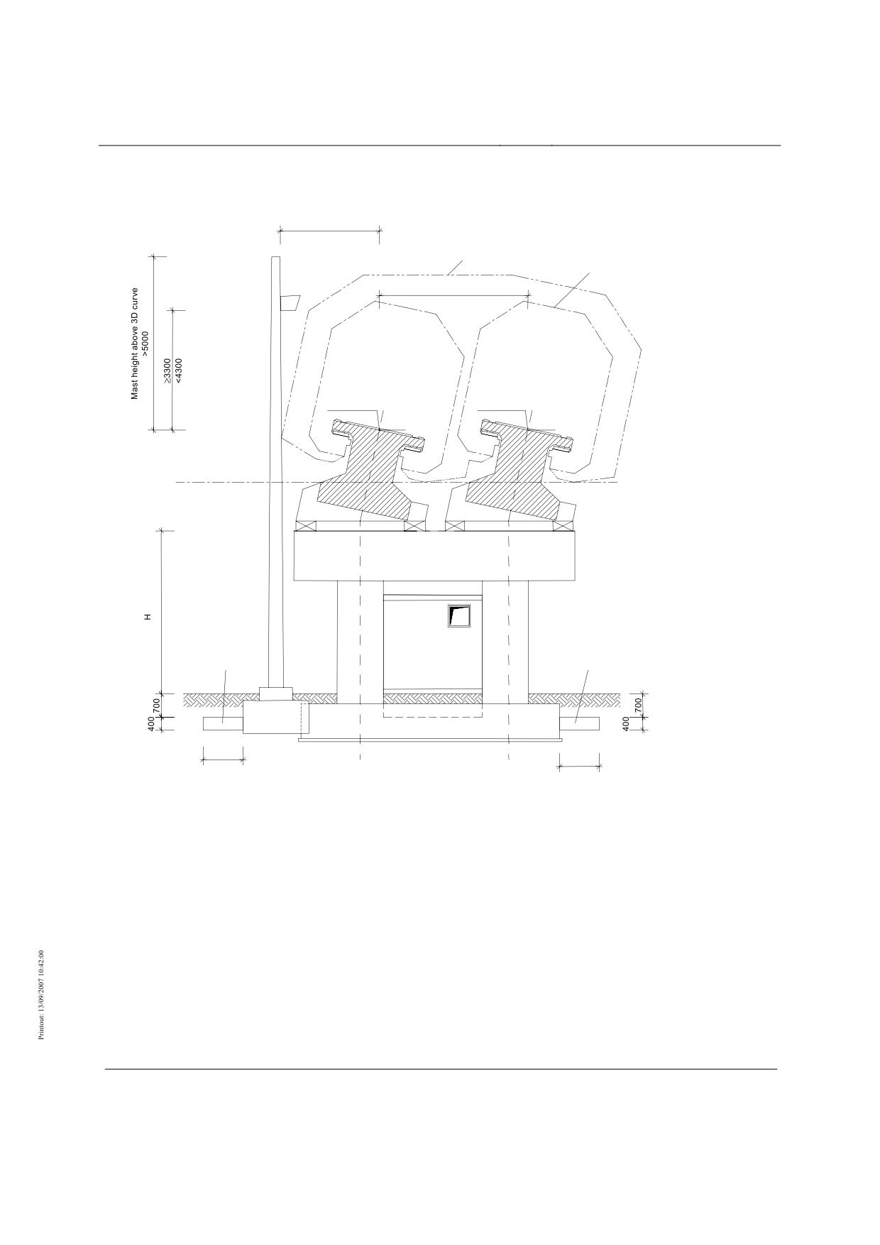
Radio mast
Minimum clearance *
3254 (12°)
(3150 2 %)
Boundary line for the
Clearance gauge
kinematic space requirement
of the vehicle
s
3D curve
3D curve
12°
12°
Walkway
level
possible
site of
switching point /
Space for cables
transformer station /
Space for cables
emergency power /
BE station
1200
1200
* except special cases
H - Headroom as per requirements for overpass of railway or road
Figure 31: Route peripherals with elevated guideway (example)
Title
High-speed Maglev System Design Principles
Complete System
Doc.No.:
50630
Version White
Issue date
15.02.2007
Page 104
paper
Rapid Maglev System
Maglev Technical
Committee
Design Principles
Complete System
Annex: High-speed Maglev System Data
Title
High-speed Maglev System Design Principles
Complete System
Doc.No.:
50630
Version White
Issue date
15.02.2007
Page 105
paper

Rapid Maglev System
Maglev Technical
Committee
Design Principles
Complete System
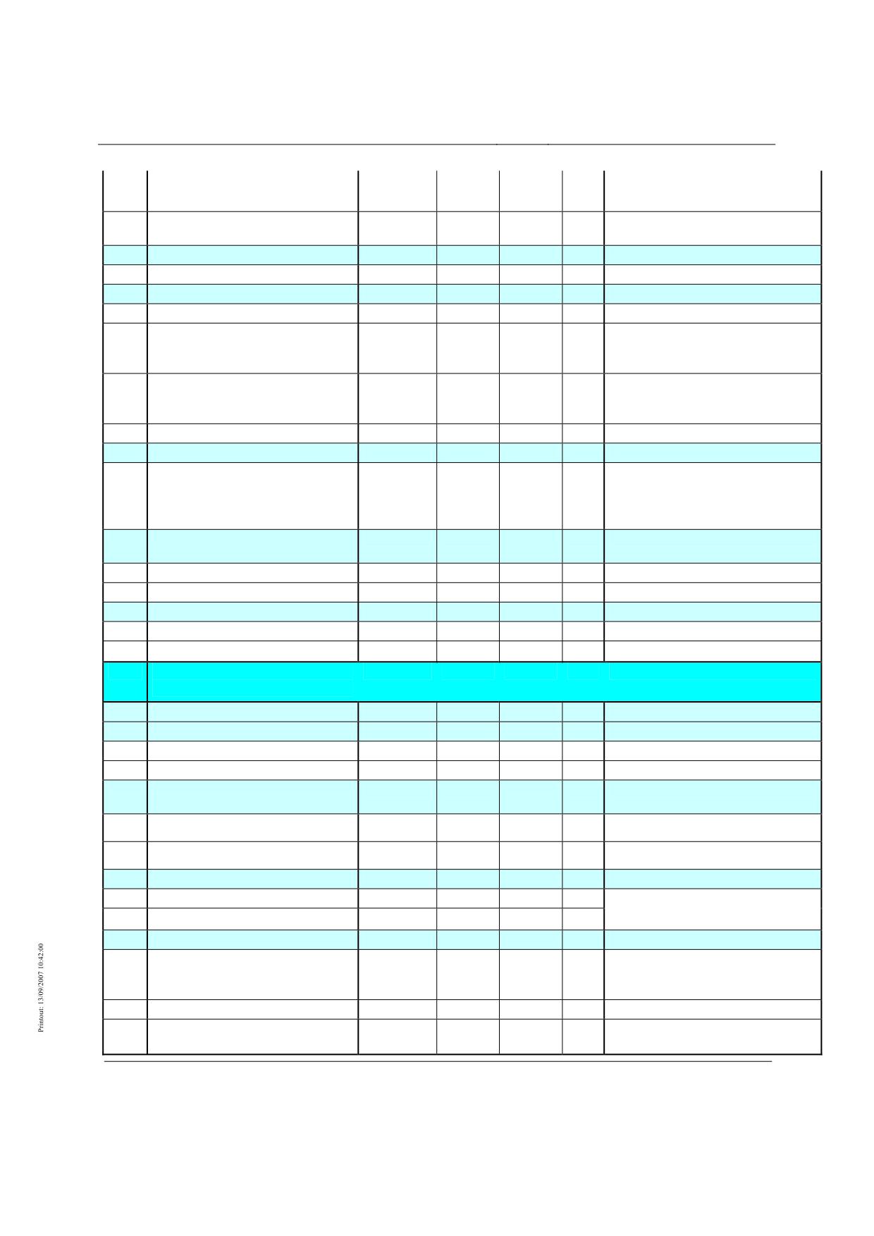
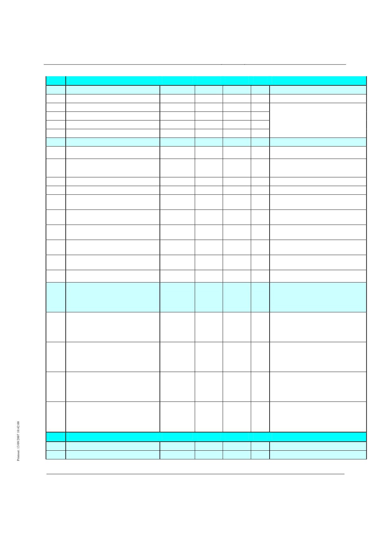
The system data defined below are required in order to design subsystems and modules of the MSB. The system data that are identified
in this Annex as "system parameters" apply to all projects. The project-specific or product-specific data (not specially identified here as
"system parameters") must be confirmed project-specifically by application of the Design Principles, or defined differently. The defini-
tions must be allowed for in the verification process.
System
Symbol
No.
Name
para-
Value
Unit
Explanation
meter
1.
Transport / operational pa-
rameters
1.1.
Speed
(1)
Maximum vehicle speed
vFz,max
500
km/h
Constant speed derived from the per-
missible continuous loads for the vehi-
cle.
(2)
Vehicle speed limit
vFz,limit
-
km/h
Constant speed derived from the per-
missible vehicle loads (special load
cases).
To be defined project-specifically based
on incident analyses.
(3)
Maximum guideway speed
vFw,max (x)
≤ 500
km/h
Position-dependent profile of the per-
missible speed for an aligned route
derived from the strength of the guide-
way.
(4)
Guideway speed limit
vFw,limit (x)
-
km/h
Position-dependent profile of the per-
missible speed for an aligned route
derived from the strength of the guide-
way under exceptional effects.
To be defined project-specifically based
on incident analyses.
1.2.
Schedule
(1)
Signal headway
-
min
Project-specific decision
2.
Track alignment
2.1.
Horizontal radius
(1)
Minimum horizontal radius
RH min
x
350
m
2.2.
Limits of transverse inclination
(1)
- in platform area
αmax (BS)
x
3
°
*) /MBbO Section 13 (3) limits the
permissible transverse inclination in the
stationary train in the platform area to
3.4 °. The max. permitted transverse
inclination of 3.0 ° for line routing is
derived from this.
(2)
- at service stopping places for opera-
αmax (HP_2)
6
°
Comfort guide value as per project-
tionally related stop
specific definition
(3)
- at other service stopping places
αmax (HP_1)
x
12
°
Title
High-speed Maglev System Design Principles
Complete System
Doc.No.:
50630
Version White
Issue date
15.02.2007
Page 106
paper
Rapid Maglev System
Maglev Technical
Committee
Design Principles
Complete System
(4)
- outside stopping places
αmax (ST)
x
12
°
MbBO Section 13, (3)
16
MbBO Section 13, (3) for approval in
individual cases
(5)
Desired transverse inclination to drain
αmin (ST)
≥ 1.15
°
equivalent to 2%
the top of the guideway beam
2.3.
Vertical radius
(1)
Minimum vertical radius
RV min
x
530
m
2.4.
Limits of linear inclination
(1)
- in platform area
smax (BS) (β)
x
5
‰
MbBO Section 13, (2)
(2)
- in areas in which standing vehicles
smax (BE) (β)
x
5
‰
MbBO Section 13, (2), exception per-
must be secured from inadvertent
mitted as per MbBO Section 5, (1)
movement
(3)
- at stopping places
smax (HP) (β)
≤ 100
‰
Defined project-specifically according
to proof of the hold function
(4)
- outside stopping places
smax (ST) (β)
x
100
‰
2.5.
Limits of guideway warp
(1)
Limits of guideway warp
∆αmax (ST)
x
0.10
°/m
up to 0.15°/m in special cases
combination of transverse inclination
over 12° and warp over 0.1°/m only
after verification in individual cases.
2.6.
Overlaying of alignment elements
(1)
Rx,z criterion
Rx,z min
x
fx,z(∆α)
m
(2)
Rx,y criterion
Rx,y min
x
fx,y(∆α)
m
2.7.
Other alignment parameters
(1)
Track centres
SM
x
≥ 4,400
mm
according to MbBO, speed-dependent
(2)
Clearance gauge
-
x
-
mm
according to MbBO
3.
Accelerations, jolts, vibra-
tion and pressures
3.1.
Acceleration
3.1.1.
Linear acceleration (x-direction)
(1)
Maximum value of drive acceleration
ax,max,accelerate
x
≤ 1.5
m/s²
MbBO Section 13, (5)
(2)
Maximum value of brake acceleration
ax,max,brake
x
≥ -1.5
m/s²
MbBO Section 13, (5)
3.1.2.
Unbalanced (free) lateral accelera-
tion (y-direction)
(1)
Line
ay,max
x
≤ 1.5
m/s²
to outside of bend, MbBO Section 13,
(4)
(2)
Track-switching device
ay,max,SWE
x
≤ 2.0
m/s²
to outside of bend, MbBO Section 13,
(4)
3.1.3.
Normal acceleration (z-direction)
(1)
Trough
az,max
≤ 1.2
m/s²
MbBO Section 13, (6), may be ex-
ceeded in individual cases (variable
(2)
Crown
az,min
≥ -0.6
m/s²
effects)
3.2.
Jolt
(1)
Lateral pressure
åy,max
0.5
m/s³
Comfort criterion, for city entrances at
constraints: up to 1.0 m/s³ in individual
cases
(2)
Lateral jolt, point at junction
åy,max,SWE
2.0
m/s³
Comfort criterion
(3)
Vertical jolt
åz,max
0.5
m/s³
Comfort criterion, in individual cases at
constraints: up to 1.0 m/s³
Title
High-speed Maglev System Design Principles
Complete System
Doc.No.:
50630
Version White
Issue date
15.02.2007
Page 107
paper
Rapid Maglev System
Maglev Technical
Committee
Design Principles
Complete System
4.
MSB Vehicle
4.1.
Vehicle configuration
(1)
Number of vehicle sections
NSekt
2 … 10
no.
(2)
Useful area per vehicle section
ANutz
-
m²
Project-specific decision
(3)
Seats per vehicle section
NSitz
-
-
(4)
Standing places per vehicle section
NSteh
-
-
(5)
Payload per vehicle section
NL
-
kg
4.2.
Vehicle geometry
Airport link - planning status 2006
(1)
Geometrical length, end section
LES
approx.
m
25
(2)
Geometrical length, centre section
LMS
x
24.768
m
see also No. 6.1.1. (3): Levitation
(system length vehicle section)
magnet occupancy length, centre
section
(3)
Geometrical length of vehicle
LFzg
m
LFZG=2*LES+(NSekt-2)*LMS
(4)
Exterior width of car body
BWK-A
x
3.7
m
(5)
Height of car body over gradient (excl.
HWK-Grd
approx.
m
Vehicle set down, to be defined project-
antenna)
3.3
specifically
(6)
Height of top of floor above gradient
HFOK-Grd
approx.
m
Vehicle set down, to be defined project-
0.93
specifically
(7)
Height of vehicle (incl. antenna) over
HFzg-Grd
approx.
m
Vehicle set down, to be defined project-
gradient
3.8
specifically
(8)
Ext. height car body over top of floor
HWK-FOK
approx.
m
to be defined project-specifically
2.4
(9)
Height of gradient over bottom of
HGrd-Fzg.UK
approx.
m
Vehicle set down, to be defined project-
vehicle
0.9
specifically
(10)
Overall height of vehicle (excl. an-
HFzg.Ges
approx.
m
to be defined project-specifically
tenna)
4.2
4.3.
Vehicle weights
The line loads given below are the
basis for the guideway design. A toler-
ance of +/- 5% of the line loads is
permissible on the vehicle side.
(1)
Dead weight of a vehicle section
MEG
≥
kg
The vehicle dead weight may not be
less than the value equivalent to a line
load of 19 kN/m averaged over the
system length of a vehicle section.
(2)
Mean weight of a vehicle section
MMG
≤
kg
The mean vehicle weight is equivalent
to a mean line load of 26 kN/m aver-
aged over the system length of a vehi-
cle section.
(3)
Permissible weight of a vehicle sec-
MZG
≤
kg
The permissible vehicle weight may not
tion
exceed the value equivalent to a line
load of 29 kN/m averaged over the
system length of a vehicle section.
(4)
Maximum weight of a vehicle section
MXG
≤
kg
The maximum vehicle weight may not
exceed the value equivalent to a line
load of 31 kN/m averaged over the
system length of a vehicle section.
5.
Guideway
5.1.
Guideway configuration
5.1.1.
Basic dimensions
Title
High-speed Maglev System Design Principles
Complete System
Doc.No.:
50630
Version White
Issue date
15.02.2007
Page 108
paper

Rapid Maglev System
Maglev Technical
Committee
Design Principles
Complete System
(1)
Stator pack system length
LSP,Sys
x
1,032
mm
see also Fig. 23 /MSB AG-
GESAMTSYS/, Chapter 8.16
5.1.2.
Standard beam lengths
(1)
Standard guideway type I
LSys,Typ I
> 16
m
Usually supported discretely on individ-
ual footings. To be defined project-
specifically.
(2)
Standard guideway type II
LSys,Type II
≤16
m
Usually supported discretely on individ-
ual footings. To be defined project-
specifically.
(3)
Standard guideway type III
LSys,Typ III
approx. 6
m
Usually supported discretely on strip
footings. To be defined project-
specifically.
5.2.
Guideway geometry
(1)
Gauge (distance between lateral
SSFE
x
2,800
mm
guide planes)
(2)
Guideway hover clearance slide
TZM,GLE-SE
x
398
mm
plane/stator plane
5.3.
Deviations of position of the func-
tional planes
5.3.1.
Tolerance guideway hover clear-
ance
(1)
Guideway hover clearance in beam
∆TZM
+3 / -5
mm
bay
(2)
Relative difference in hover clear-
± 0.4
mm
ances at beam joint
5.3.2.
Gauge width tolerance
(1)
Gauge width in beam bay
max ∆S
± 2
mm
(2)
Relative gauge difference at beam
± 1
mm
joint
5.4.
Guideway superstructure deforma-
tion
5.4.1.
in x-direction due to traffic
(1)
at beam joint
10
mm
periodical
20
with autom. braking
5.4.2.
in z-direction due to traffic
(1)
Single-bay beam
max fz,Fzg
x
LSt/4,000
mm
with static effect at permissible vehicle
weight
(2)
Dual-bay beam
x
LSt/4,800
mm
with static effect at permissible vehicle
weight
(3)
Guideway plates
The construction must be assessed in
individual cases.
5.4.3.
in y-direction due to traffic
(1)
Single-bay beam
max fy,Fzg
x
LSt/15,000
mm
with static effect at permissible vehicle
weight and ay,max
(2)
Dual-bay beam
x
LSt/18,000
mm
with static effect at permissible vehicle
weight and ay,max
(3)
Guideway plates
The construction must be assessed in
individual cases.
5.5.
Track-switching devices
(1)
Turnaround time of a 2-way point from
30
s
Typical value
end position to end position
6.
Geometry of the vehi-
cle/guideway interfaces
6.1.
Levitation magnet / long stator
Title
High-speed Maglev System Design Principles
Complete System
Doc.No.:
50630
Version White
Issue date
15.02.2007
Page 109
paper

Rapid Maglev System
Maglev Technical
Committee
Design Principles
Complete System
6.1.1.
Levitation magnet
(1)
Levitation magnet system length
Lsys,TM
x
3,096
mm
(standard length magnet)
(2)
Levitation magnet centres in y-
ey,TM
x
2,220
mm
direction
(3)
Levitation magnet occupancy length
LTM-B,MS
x
24,768
mm
centre section
(4)
Levitation magnet occupancy length
LTM-B,ES
23,753
mm
no system dimension, may vary pro-
end section
ject-specifically
6.1.2
Long stator
(1)
Lang stator centres in y-direction
ey,SP
x
2220
mm
Nom. dim.
(2)
Width of stator pack (geometrical)
by,SP
≥ 185
mm
Typical embodiment: 185 mm, to be
defined project-specifically
(3)
Pole centres
ex,pole centres
x
258
mm
Nom. dim., 3-phase motor winding
(4)
Slot pitch (centres of the motor wind-
ex,slot pitch
x
86
mm
Nom. dim.
ing cable)
6.2.
Guide magnet - lateral guide rail
6.2.1.
Guide magnet
(1)
Guide magnet system length
Lsys,FM
x
3,096
mm
6.2.2.
Lateral guide rail
(1)
Lateral guide rail height
hSFS
x
310
mm
(2)
Lateral guide rail thickness
dSFS
≥ 30
mm
30 mm, Typical embodiment, to be
defined project-specifically
6.3.
Brake magnet - lateral guide rail
(1)
Brake magnet centres in x-direction
ex,BM
24,768
mm
Guide value, different dimensions may
be defined project-specifically.
6.4.
Support skid / slide plane
6.4.1
Support skid
(1)
Support skid length
Lx,TK
740
mm
Guide value, different dimensions may
be defined project-specifically.
(2)
Support skid width
by,TK
110
mm
Guide value, different dimensions may
be defined project-specifically.
(3)
Skid centres in x-direction
ex,TK
3,096
mm
(4)
Skid centres in y-direction
ey,TK
x
2,220
mm
6.4.2
Slide plane
(1)
Slide plane / slide rail width
min by,GL
≥ 150
mm
7.
Effects at the vehi-
cle/guideway interfaces in x-
direction
(1)
Variable effects with drive/brakes
max stat px
4.8
kN/m
Local maximum; mean over a vehicle
section 4.4 kN/m for a centre section of
length 24.768 m.
Drive current is limited so that the
maximum permissible force is not
exceeded.
(2)
Exceptional effects (symmetrical)
max px
10.0
kN/m
Equivalent to approx. 250 kN/vehicle
section
for a centre section of length 24.768 m
Title
High-speed Maglev System Design Principles
Complete System
Doc.No.:
50630
Version White
Issue date
15.02.2007
Page 110
paper
Rapid Maglev System
Maglev Technical
Committee
Design Principles
Complete System
(3)
Exceptional effects (asymmetrical)
max px r,l
5.5
kN/m
Equivalent to a maximum total force of
or 2.0
185 kN/vehicle section for a centre
section of length 24.768 m and a
maximum uneven distribution of 0.73 :
0.27 between the two guideway/vehicle
sides
8.
Drive
8.1.
Motor geometry
see Levitation magnet and Long stator
-
8.2.
Motor constants
(1)
Shear force constant per centre sec-
cM,MS
-
N/A
Correlated quantity equation: cM,MS =
tion
43.0 * √(mMS[t] / 64.5 t)
with mMS - actual weight of centre
section
Values may vary at very high and very
low temperatures due to the expansion
of long MSB vehicles.
(2)
Shear force constant per end section
cM,ES
-
N/A
Correlated quantity equation: cM,ES =
41.3 * √(mES[t] / 62.0 t)
with mES - actual weight of end section
Values may vary at very high and very
low temperatures due to the expansion
of long MSB vehicles.
(3)
Induced motor voltage per vehicle
up
-
V
Equivalent to 1/6 * cM * speed
section long side
(4)
Conductor cross-section
AS
300
mm
Guide value for aluminium conductor
(5)
Conductor resistance
RS
0.23
Ω
Guide value per km stator length at
20°C and 0-30 Hz
(6)
Resistance/temp. coefficient
θSt
0.004
1/°C
Guide value factor is:
(1+θSt*(temperature-20°C))
(7)
Resistance/frequency coefficient
fSt
0.004
s
Guide value factor is: (1+fSt*(frequency-
30Hz))
(8)
Leakage inductance
LS
2.6
mH
Guide value per km stator length with-
out vehicle
(9)
Vehicle magnetizing inductance
Lh
0.1
mH
Guide value per section and side incl.
LS
(10)
Earth capacitance
CS
1
uF
Guide value per km stator length
(11)
Length factor moving field line/long
2.35
Guide value
stator
(12)
Max. conductor temperature
TLmax
70
°C
Guide value for service life reasons,
technically 90°C
(13)
Thermal time constant
τStat
1...5
h
Guide value
(14)
Nom. voltage
UNenn
10...20
kV
Guide value interlinked fundamental
component rms
8.3.
Motor interconnection
(1)
Motor section length
ds
1,200
m
Guide value, individually between
approx. 0.5 and 3 km
(2)
Motor section offset
vers
300
m
Guide value, individually between 0
and ds/2
9.
Operation Control System
9.1
Safe positioning
Title
High-speed Maglev System Design Principles
Complete System
Doc.No.:
50630
Version White
Issue date
15.02.2007
Page 111
paper

Rapid Maglev System
Maglev Technical
Committee
Design Principles
Complete System
(1)
Positional information tolerance, static
2
m
Typical value. The value must be de-
termined project-specifically.
(2)
Speed information tolerance
5
km/h
Typical value. The value must be de-
termined project-specifically.
9.2
Vehicle-related speeds
(1)
Setdown speed
5
km/h
Typical value. The value must be de-
termined project-specifically.
9.3
Deceleration and running times
(1)
Max. drive shutdown time
2.3
s
Guide value for the shutdown time of
the drive and braking energy for a
safety-relevant shutdown reason by the
OCS
10.
Aerodynamics
10.1.
Pressure during vehicle passage
(1)
Max. pressure amplitude on the vehi-
x
2,400
Pa
cle sides
(2)
Pressure amplitude on structures on
-
Pa
dependent on clearance and vehicle
the guideway
speed
(3)
Pressure load on guideway table and
x
-7.6 to
kN/m2
vehicle underfloor
15.2
10.2.
Pressure in tunnel
(1)
Design pressure for tunnel design
5,500
Pa
Differential pressure vehicle inte-
rior/exterior
(2)
Design pressure for vehicle design
6,000
Pa
Differential pressure vehicle inte-
rior/exterior
Title
High-speed Maglev System Design Principles
Complete System
Doc.No.:
50630
Version White
Issue date
15.02.2007
Page 112
paper
Rapid Maglev System
Maglev Technical
Committee
Design Principles
Complete System
Title
High-speed Maglev System Design Principles
Complete System
Doc.No.:
50630
Version White
Issue date
15.02.2007
Page 113
paper
Rapid Maglev System
Maglev Technical
Committee
Design Principles
Complete System
Title
High-speed Maglev System Design Principles
Complete System
Doc.No.:
50630
Version White
Issue date
15.02.2007
Page 114
paper
High-speed Maglev System
Maglev Technical
Committee
Design Principles
Complete System
High-speed Maglev System
Design Principles
Complete System
Annex 1
Abbreviations and definitions
The author reserves the copyright in this document and all attachments.
All rights reserved
Title
High-speed Maglev System Design Principles
Complete System, Annex 1 Abbreviations and Definitions
Doc.No.:
67536
Version White pa-
Issue date
15.02.2007
Page 1
per
High-speed Maglev System
Maglev Technical
Committee
Design Principles
Complete System
Distribution
This document has been released for publication by the Technical Committee "Complete Sys-
tem".
Title
High-speed Maglev System Design Principles
Complete System, Annex 1 Abbreviations and Definitions
Doc.No.:
67536
Version White pa-
Issue date
15.02.2007
Page 2
per
High-speed Maglev System
Maglev Technical
Committee
Design Principles
Complete System
Change history
Release date: 15.02.2007; white paper, Technical Committee "Complete System"
Title
High-speed Maglev System Design Principles
Complete System, Annex 1 Abbreviations and Definitions
Doc.No.:
67536
Version White pa-
Issue date
15.02.2007
Page 3
per
High-speed Maglev System
Maglev Technical
Committee
Design Principles
Complete System
List of contents
1 Distribution
2
2 Change history
3
3 List of contents
4
4 General
5
4.1 Purpose of the document, scope
5
4.2 High-speed Maglev System Design Principles
5
4.3 Abbreviations and definitions
5
4.4 Statutes, regulations, standards and directives
5
4.5 Identification and binding value of requirements
6
5 Overviews
7
6 Abbreviations
9
7 Definitions
21
List of illustrations
Figure 1: Chart of operation, modes
7
Figure 2: Chart of speed terms
8
Title
High-speed Maglev System Design Principles
Complete System, Annex 1 Abbreviations and Definitions
Doc.No.:
67536
Version White pa-
Issue date
15.02.2007
Page 4
per
High-speed Maglev System
Maglev Technical
Committee
Design Principles
Complete System
General
Purpose of the document, scope
This document contains abbreviations and definitions for high-speed maglev systems.
These design principles apply to a high-speed maglev system according to the General
Maglev System Act /AMbG/.
High-speed Maglev System Design Princi-
ples
This document is an annex to the Design Principles Complete System and so forms part of a
documentation for high-speed maglev systems consisting of several design principles. The
document tree is shown in Figure 1 /MSB AG-GESAMTSYS/.
The high-level "complete system" design principles and their annexes apply uniformly for the
whole documentation:
•
High-speed Maglev System Design Principles Complete System, Doc. No.: 50630,
/MSB AG-GESAMTSYS/
•
Annex 1: Abbreviations and Definitions, Doc. No.: 67536, /MSB AG-ABK&DEF/
•
Annex 2: Statutes, Regulations, Standards and Directives, Doc. No.: 67539, /MSB
AG-NORM&RILI/
•
Annex 3: Environmental Conditions, Doc. No.: 67285, /MSB AG-UMWELT/
•
Annex 4: Rules for Operation and Maintenance, Doc. No.: 69061, /MSB AG-
BTR/
•
Annex 5: Noise, Doc. No.: 72963, /MSB AG-SCHALL/
Abbreviations and definitions
Abbreviations and definitions are listed in this document.
Further specific abbreviations and definitions may be defined in the lower-level design prin-
ciples.
Statutes, regulations, standards and direc-
tives
The normative documents listed in /MSB AG-NORM&RILI/ contain requirements that form
part of the High-speed Maglev System Design Principles by cross reference in the High-speed
Maglev System Design Principles. Where normative documents in /MSB AG-NORM&RILI/
are dated, subsequent changes or revisions of these publications do not apply. With undated
references, the latest version of the normative document that is referred to applies.
Title
High-speed Maglev System Design Principles
Complete System, Annex 1 Abbreviations and Definitions
Doc.No.:
67536
Version White pa-
Issue date
15.02.2007
Page 5
per
High-speed Maglev System
Maglev Technical
Committee
Design Principles
Complete System
The version of the standards and directives to be observed in an MSB project must be decided
bindingly on a project-specific basis.
Identification and binding value of require-
ments
The requirements of /DIN 820/ were essentially applied in the preparation of this document.
In the following chapters and the annexes of this document
•
Requirements are shown in normal font
•
Explanations, guide values and examples are shown in italics
The degree to which the requirements are binding has been defined by reference to /DIN 820-
2/ Annex G, and has been taken into consideration when formulating the individual require-
ments.
Title
High-speed Maglev System Design Principles
Complete System, Annex 1 Abbreviations and Definitions
Doc.No.:
67536
Version White pa-
Issue date
15.02.2007
Page 6
per
High-speed Maglev System
Maglev Technical
Committee
Design Principles
Complete System
Overviews
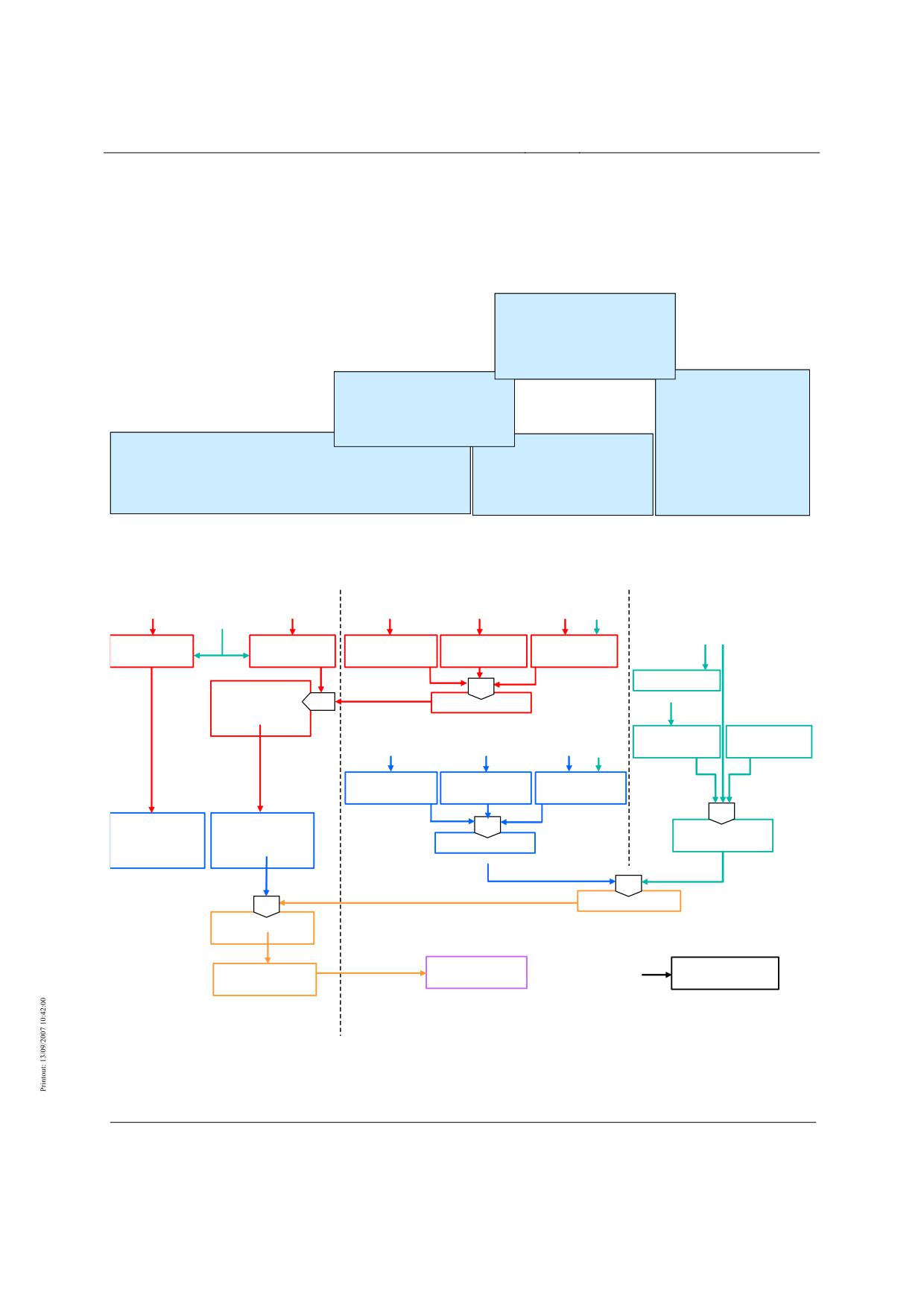
The following terms and definitions must be used for the High-speed Maglev System Design
Principles.
The terms and definitions are summarised alphabetically below in Chapters 0 and 0.
Operation
Operation is the totality of all
measures used to carry persons
and goods (Section 2, (1)
/MbBO/)
Train operations
Maintenance
Preparation and execution of
Combination of all technical and
journeys with vehicles and
administrative measures
special vehicles.
including
monitoring measures with which
Normal operation
Departure from normal operation
an item is maintained in, or restored
to, its functional condition
Fully technically protected train operations.
Not fully technically protected train
Note: The term ‚normal operation’ is the result of an operational analysis according to MbBO §24
(according to EN 50129/)
operations under
personnel responsibility.
Figure 32: Chart of Operation, Modes
Special loads
Alignment
Project inputs
Alignment
(noise control, energy demand,
comfort values, journey times etc)
Safe levitation
Safe braking
Vehicle speed
Tunnel speed
Guideway
profile
profile
limit
limit
speed limit
Design speed
min
Limiting running
min
Line speed limit
profile
Recomm. speed
Max. operating
Continuous loads
Alignment
for comfort
speed
Safety engineering
responses
Max. vehicle
Max. tunnel
Max. guideway
speed
speed
speed
min
min
Recommended
Min. running
Max. running
Max. line speed
line speed
profile
profile
for tech. reasons
not for tech. reasons
Drive control
tolerance,
min
Positioning toleranc
Nominal speed
min
Nominal running
profi
le
Drive pe
rformance
Project-dependent
Failure scenarios
Minimum line
special decisions
Technical maximum
Actual running
speed
speed
profile(s)
SP related
non SP related
Title
High-speed Maglev System Design Principles
Complete System, Annex 1 Abbreviations and Definitions
Doc.No.:
67536
Version White pa-
Issue date
15.02.2007
Page 7
per
High-speed Maglev System
Maglev Technical
Committee
Design Principles
Complete System
Figure 33: Chart of Speed Terms
Notes on the "Chart of Speed Terms":
The speed terms are divided up into:
•
stopping place-related speeds ("profiles") for the approach to stopping places, and
•
non stopping place-related speeds ("speeds")
Only profiles are directly monitored by the safety systems.
Stopping place-related:
The alignment and various system characteristics determine the safe levitation profile and the
safe braking profile.
The minimum and maximum running profiles of the stopping place are obtained by forming
the minimum value with the line speed limit (leads to the limiting running profile) and allow-
ing for the safety-technical reactions. These profiles are monitored by the OCS to ensure safe
compliance with the safe levitation profile / braking profile and/or the limiting running pro-
file. The nominal running profile which should be run by the drive is obtained after deducting
drive control tolerances and positioning tolerances and allowing for the nominal speed. The
profile which the drive actually runs because of its efficiency is known as the actual profile. A
minimum line speed which can still be run in operation and that is independent of stopping
places also arises from defined failure scenarios of the drive.
Not stopping place-related:
The defined special loads and the alignment determine the corresponding speed limits for
vehicle, tunnel and guideway. The minimum of these three components is referred to as the
line speed limit. This limit must never be exceeded and so forms part of the limiting running
profile.
The defined continuous loads for vehicle, tunnel and guideway determine the corresponding
maximum speeds. The minimum of the three components it the maximum line speed. This
represents the restriction on the nominal speed for technical reasons. There is also the rec-
ommended line speed as a further limitation on the nominal speed. This consists of comfort-
related and possibly other non safety-related project inputs. The nominal speed forms part of
the nominal running profile (see above).
In addition to all other speeds there is the technical maximum speed which, on a project-
specific basis, is the maximum speed that may be run under defined special conditions, e.g.
for individual journeys for verification purposes.
Title
High-speed Maglev System Design Principles
Complete System, Annex 1 Abbreviations and Definitions
Doc.No.:
67536
Version White pa-
Issue date
15.02.2007
Page 8
per
High-speed Maglev System
Maglev Technical
Committee
Design Principles
Complete System
Abbreviations
Abbreviation
Definition
p
averaged, static line load
α
Guideway transverse inclination
α
Ellipsoidal azimuth at the zero point (P0) of the inclined conform projec-
tion (MKS)
α’
Change in transverse inclination of guideway (superelevation angle)
β
Guideway linear inclination (incline +, decline -) of the three-
dimensional guideway axis
∆
Delta, difference
δ or δxy
Yaw angle (rotation about the z-axis)
∆α
Angular deviation of the y-z-plane, change in guideway transverse incli-
nation (guideway warp)
∆αmax
Maximum permissible guideway warp
∆αy
Difference in the unbalanced lateral acceleration from sinusoid or clot-
hoid end and beginning
∆αz
Difference in the normal acceleration of clothoid end and beginning
∆λ
Ellipsoidal linear difference relative to P0
∆ϕ
Ellipsoidal width difference relative to P0
∆Τ
Linear temperature difference
δ0xy
Static yaw angle due to load asymmetry
∆Fpz
Deviation of z-oscillation force from nominal load
∆fy
Force-dependent static y-downward deflection of the chassis structure
with excited guide magnet and deviation from nominal load
∆fz
Force-dependent static downward / upward deflection with deviations
from the nominal load
∆fzG
Force-dependent static downward / upward deflection of the chassis
structure with deviations from the nominal load
∆fzTK
Static deflection of the support skid with vehicle setdown
∆fzTM
Force-dependent static downward / upward deflection of the levitation
magnet link with deviations from the nominal load
∆P
Wear to guide magnet pole strip
∆s
Dynamic gap deviation, air gap levitation/guidance
∆s1
Gap difference at guide magnet centre on bends
∆s2
Gap difference at guide magnet end on bends
∆T0
Linear temperature difference between top and bottom of beam at which
nominal precamber /MSB AG-FW GEO/ occurs in the unstressed condi-
tion
∆TM
Linear temperature difference
∆TM,y
Linear temperature difference in y-direction
Title
High-speed Maglev System Design Principles
Complete System, Annex 1 Abbreviations and Definitions
Doc.No.:
67536
Version White pa-
Issue date
15.02.2007
Page 9
per
High-speed Maglev System
Maglev Technical
Committee
Design Principles
Complete System
Abbreviation
Definition
∆TM,z
Linear temperature difference in z-direction
∆TN
Total variation in constant temperature component
∆Tre/li
Temperature difference of the right and left side
∆VTK
Support slid lining wear
∆Wy
y-construction tolerances, guideway gauge
∆Wz
z-construction tolerances, guideway hover clearance
∆xA,E
Dimension for the distance from system axis to beam beginning and end
∆y
y-construction tolerances, vehicle gauge
∆yi
y-offset, levitation frame i
∆z
z-construction tolerances, vehicle hover clearance
∆zi
z-offset, levitation frame i
η
Angle of articulation
η or ηyz
Roll angle (rotation about x axis)
η0yz
Static roll angle due to load asymmetry
ηyzα’
Roll angle of car body from guideway superelevation
ηyzFy
Roll angle of car body from mass force and side wind
γ
Factor of safety, partial factor of safety
γ bzw. γxz
Pitch angle (rotation about y axis)
γ0xz
Static pitch angle due to load asymmetry
γA
Partial factor of safety for exceptional effects
γG
Partial factor of safety for continuous effects
γQ
Partial factor of safety for variable effects
λ
Ellipsoidal length
λ
Wavelength of vehicle-side excitations or effects
λ0
Ellipsoidal length of the projection zero point
µ
Weight per unit area of the guideway beam
µ
Coefficient of friction
µH
Coefficient of friction for the holding brake function
µH min
Minimum coefficient of friction for the holding brake function on an
iced guideway
ϕ
Dynamic superelevation factor, vibration coefficient
ϕ
Ellipsoidal width
ϕ0
Ellipsoidal width of the projection zero point
ψ
Combination factor
ψ0
Combination factors for variable effects
ψ1
Combination factors for frequent effects (/1/week)
ψ1'
Combination factors for non frequent effects (1/year)
ψ2
Combination factors for quasi-continuous effects
ρ°
Symbol rho, factor for converting the unit radian to degree [°]
Title
High-speed Maglev System Design Principles
Complete System, Annex 1 Abbreviations and Definitions
Doc.No.:
67536
Version White pa-
Issue date
15.02.2007
Page 10
per
High-speed Maglev System
Maglev Technical
Committee
Design Principles
Complete System
Abbreviation
Definition
τ
Points angle tau
ϑ
Tangential torsion at beam joints
a
Acceleration, deceleration
a
In the MKS: lateral distance from the geodetic line projected true-to-
length
a
Outside track
A
Clothoid parameter
A
Start
A
Area
A
Lift
A
Load cases of exceptional effects
a(t)
Acceleration amplitude at time t
ABE
Drive sector
aeff or aRMS
Root-mean-square of acceleration
ai
Acceleration in x ,y ,z direction (i=x,y,z)
ai max
Maximum acceleration in x ,y ,z direction (i=x,y,z) (S-loads)
ai mitt
Mean operational acceleration in x ,y ,z direction (i=x,y,z)
(A-loads)
AL
Starting strip
AW
Lift from wind effects
ax
Drive and braking acceleration
ax max
Permitted maximum value for the drive and braking acceleration
ay
Unbalanced free y-lateral acceleration (on bends)
ay max
Permissible maximum value for the unbalanced free lateral acceleration
az
Normal acceleration (g + trough/crown run)
az max
Permissible maximum value for normal acceleration
B, b
Width (general)
bG
Maximum lateral distance of a passenger from the three-dimensional
curve (centre of the outside seat in each case)
Bg
Component, global
BHPL
Service stopping place
Bl
Component, local
OCS
Operation Control System
BM
Braking magnet
BSK
Fire safety concept
BZ
Operations centre
c
Spring constant
cηWK
Roll rigidity of car body, relative to pendulum
CAD
Computer Aided Design
cpiE
Rigidity of the z-setdown spring i, relative to the pendulum axis
cZF
Rigidity of y-auxiliary spring
Title
High-speed Maglev System Design Principles
Complete System, Annex 1 Abbreviations and Definitions
Doc.No.:
67536
Version White pa-
Issue date
15.02.2007
Page 11
per
High-speed Maglev System
Maglev Technical
Committee
Design Principles
Complete System
Abbreviation
Definition
d
Distance of guide magnet gap sensors
D
Damping factor, Lehr's damping factor
D
Permissible conflict between outward and return path of geometrical
levelling
D
Pressure
DIN
Deutsches Institut für Normung (German Standards Institute)
DSV
Three-step method
dyn
dynamic
e
Distances in general, centres
E
End
E
Elastic modulus
E
Outcomes of effects (deformation, <stress resultants, stresses, bearing
forces)
EBA
Eisenbahn-Bundesamt (German Federal Railway Authority)
EFT
Single-bay beam
EG
Load case designation for vehicle tare weight
EI
Flexural strength
elas
elastic
Em
Mean actual value of a line observation
EMF
Electromagnetic fields
EMS
Electromagnetic levitation
EMC
Electromagnetic compatibility
EN
European Standard
EP
End pole of the levitation magnets
ES
End section
ESD
Electrostatic discharge
EVU
Energy utility company
f
Frequency; deformation
F
Force
FA
Aerodynamic running resistance
FA
Vehicle exterior,
FB
Running resistance from on-board energy generation
FBrems
Braking force of the vehicle through the effect of vehicle-side brakes
FEM
Finite Element Method
FG
Total braking force of the vehicle
FH
Holding brake force
FI
Vehicle interior,
FKz1
z-coupling force, section coupling end section 1 to centre section
FKz2
z-coupling force, section coupling end section 2 to centre section
FM
Running resistance from magnetisation of stator and lateral guide rail
FM
Guide magnet
Title
High-speed Maglev System Design Principles
Complete System, Annex 1 Abbreviations and Definitions
Doc.No.:
67536
Version White pa-
Issue date
15.02.2007
Page 12
per
High-speed Maglev System
Maglev Technical
Committee
Design Principles
Complete System
Abbreviation
Definition
FMEA
Failure Mode & Effect Analysis
FMT
Section of guide magnet assigned to a guidance control circuit = partial
magnet
FmWKy
y-inertial force of car body (superelevation deficit)
FmWKz
z-inertial force of car body
Fp1z
z-oscillation force, tail levitation frame, end section
Fpiy
y-oscillation force, levitation frame i
Fpiz
z-oscillation force levitation frame i
FpzLFi
z-oscillation force air suspension circuit i
FW
Running resistance of the vehicle
FW
Guideway
Fx,Schub
Drive force installed in the guideway
FxTM
x-force at the levitation magnet link
FyFM
y-force at the guide magnet link
FyFM0
Guide magnet preload
FySW
Side wind force on end section E, centre section M
FyWK
y-forces car body end section E, centre section M
fz
z-offsets
fz,Fzg
Deformation of guideway in z-direction by the maglev vehicle
fz,Fzg,max
Maximum deformation of guideway in z-direction by the maglev vehi-
cle
FZFiy
y-force at y-aux. spring levitation frame i
Fzg
Vehicle
FzTM
z-force at the levitation magnet link
FzWK
z-forces car body end section E, centre section M
g
Normal case acceleration (acceleration due to gravity
G
Weight
G
Load cases continuous effects
G
Shear modulus
GAv
Shearing rigidity
ges, Ges
total
GL
Slide rail
GLE, GE
Slide plane
GLM
Slide rail centres
GPS
Global Positioning System
H
horizontal
H, h
Height (general)
HG
Load case name for increased vehicle weight
hG,Gelände
Gradient height above grade after completion
HIC
Head Injury Criterion
HL
Northing in the national system
Title
High-speed Maglev System Design Principles
Complete System, Annex 1 Abbreviations and Definitions
Doc.No.:
67536
Version White pa-
Issue date
15.02.2007
Page 13
per
High-speed Maglev System
Maglev Technical
Committee
Design Principles
Complete System
Abbreviation
Definition
HP
Main pole of the levitation magnets
i
Inside track
I
Moment of inertia
i, j
Integer control variable
IH
Maintenance
ILT
Infrastructure control system
INKREFA
Incremental Vehicle Location System
K
Curvature, reciprocal of radius
K
Crown
k
Factor, coefficient
Kw
Shortwave deviation
l
left, left-hand
L
Length (general)
LA
Long-stator centreline
Lb
Clear width
Le
Total length of an alignment element
LES
Vehicle length, end section
LFM
Magnet length, guide magnet
LFM-B
Guide magnet occupancy length of the vehicle
LFw
Length, bay width from support centres
Li
Beam segment length
LK
Length of clothoid
LK min
Minimum length of clothoid
LM
System length of a module in x-direction
LMS
Vehicle length, centre section
LP
Length of the element up to point P
lp
Pendulum length
LPZ
Lighting Protection Zone as per /DIN EN 62305-1/
LRL
Location reference lug
LS
Length of sinusoid
LS min
Minimum length of sinusoid
LSt
Guideway beam spans (centres between bearing axes, usually a multiple
of 1.032 m and relative to the centres of the support axes in the 3D
curve)
LSys
System length of the beam
LTangente
Tangential length
LTM
Levitation magnet length
LTM-B
Levitation magnet occupancy length of the vehicle
Lv
Length distortion as scale difference
Lw
Long-wave deviation
m
Masse
Title
High-speed Maglev System Design Principles
Complete System, Annex 1 Abbreviations and Definitions
Doc.No.:
67536
Version White pa-
Issue date
15.02.2007
Page 14
per
High-speed Maglev System
Maglev Technical
Committee
Design Principles
Complete System
Abbreviation
Definition
m
Linear effects due to torsion
M
Moment (general)
M
Modular construction
max
maximum
mb
Set-down component of the vehicle mass
MbBO
Magnetschwebebahn-Bau- und Betriebsordnung (Maglev Construction
and Operation Regulations)
MDT
Mean Down Time
MFE
Mechanical guidance element, e.g. guide magnet strips or startup strips
MG
Load case designation for mean vehicle weight
min
minimum
MKS
Maglev coordinate system
MRE
Magnet control unit
MREB
Magnet control unit, braking
MREF
Magnet control unit, guidance
MRET
Magnet control unit, levitation
MRK
Magnet control circuit comprising of the control circuit elements: mag-
net, magnet control unit and if necessary the gap measuring unit
MS
Centre section
MSB
Magnetic levitation railway, high-speed maglev system
mSekt
Total weight of a vehicle section (with or without payload)
MSF
Scale factor of the projection distortion
MSH
Special magnetic steel from the 'Heinrichshütte' (special magnetic steel
with good magnetic properties)
MT
Car body rolling moment
MTBF
Mean Time Between Failures
MTTR
Mean Time to Repair
mWK
Mass of car body
n
Number, general
n
Number of sections
N
Number of bays of a beam
NBT
Normal operation
NGK
Inclination change criterion [mm/m]
NL
Payload
NLÜ
Payload excess
NT
Slot arm
o
top
OG
Upper chord, top of guideway
OK
Top, top edge
P
Maximum pole strip wear
P
Any desired point on the alignment element
Title
High-speed Maglev System Design Principles
Complete System, Annex 1 Abbreviations and Definitions
Doc.No.:
67536
Version White pa-
Issue date
15.02.2007
Page 15
per
High-speed Maglev System
Maglev Technical
Committee
Design Principles
Complete System
Abbreviation
Definition
P0
Zero point for the MKS, also the apex of the ellipsoidal azimuth and
projection zero point
PK
Pole core
PL
Pole strip
plas
plastic
PMitte
Point in the centre of the alignment element
PRW
Rotor angle
px, py, pz
Line or track load x, y and z direction
Q
Load cases of variable effects
QS
Quality assurance
qx, qy, qz
Area load in x, y and z direction
r
Earth radius
r
right, right-hand
R
Guideway radius of curvature
R
Radius
R
Regulation
RAMS
R
- Reliability
A
- Availability
M
- Maintainability
S
- Safety
RH
Horizontal radius
RH
Horizontal curve radius
RH min
Minimum permissible horizontal radius
RH,P
Horizontal radius at point P
RK,W
Vertical radius (crown, trough in the gradient) ≡ RV
RKK
Three-dimensional curve coordinate system
RKK
Three-dimensional curve coordinate system
Rl
Regulation
Rm
Mean earth radius (for calculating projection distortions)
RMS
RMS Value (Root Mean Square)
RV
Vertical radius
RV
Vertical curve radius
RV min
Minimum permissible vertical radius
Rx,y
Three-dimensional radius by overlaying a gradient curvature (radius)
with a horizontal curvature (radius)
Rx,z
Three-dimensional radius by overlaying horizontal curvature and gradi-
ent curvature
Rx,zmin
Minimum permissible three-dimensional radius (as a function of the
guideway warp)
Rxy
Curve radius
s
Section, distance
Title
High-speed Maglev System Design Principles
Complete System, Annex 1 Abbreviations and Definitions
Doc.No.:
67536
Version White pa-
Issue date
15.02.2007
Page 16
per
High-speed Maglev System
Maglev Technical
Committee
Design Principles
Complete System
Abbreviation
Definition
S
Guideway gauge
S
Track centres
S
Gap dimension
S
Wake
S
Centre of gravity
s0
Nominal air gap levitation magnet / guide magnet
SA
Stator section
SB
Safe Brake
SE
Stator plane
Sekt
Section
SF
Nominal gap, guiding
SFE
Lateral guide rail plane
SFS
Lateral guide rail
SFZ
Railway vehicle
SGN
Sign (algebraic) of a number
SIAB
sichere Antriebsabschaltung (safe drive shutdown)
SK
Lateral force
SP
Stator pack
SPB
Stator pack mounting, fastener
SPD
Surge Protection Device as per
/DIN EN 62305-1/
SR
Nominal gap, guiding on bend
SS
Number of vibration cycles
St
Support, support point, span
ST
Support skid gap
stat
static
SW
Safety wind
t
Sheet metal thickness
t
Time
T
Temperature
T0
Nominal / construction temperature
TFK
Beam fabrication coordinate system
TK
Support skid
Tl
Temperature of the left-hand edge of the loadbearing cross-section
TM
Levitation magnet
TMT
A "levitation magnet half" (= partial magnet) assigned to a levitation
control circuit
To
Object temperature at the upper chord
TP
Trigonometrical survey point
Tr
Temperature of the right-hand edge of the loadbearing cross-section
TRS
Traction regulation and control
Title
High-speed Maglev System Design Principles
Complete System, Annex 1 Abbreviations and Definitions
Doc.No.:
67536
Version White pa-
Issue date
15.02.2007
Page 17
per
High-speed Maglev System
Maglev Technical
Committee
Design Principles
Complete System
Abbreviation
Definition
Tu
Object temperature at the lower chord
TVE
Transrapid Versuchsanlage Emsland (Transrapid Test Facility)
tZM
Hover clearance (nominal dimension distance stator plane to slide plane)
u
bottom
URS
Converter regulation and control
USV
Uninterruptible Power Supply (UPS)
UW
Substation
v
Speed
V
Vertical
V
Offset
V
Transfer force (at bearers)
VDE
Verband Deutscher Elektrotechniker (German Association for Electri-
cal, Electronic & Information Technologies)
VDI
Verein Deutscher Ingenieure (German Institute of Engineers
ve
Design speed
vEinsatz
Working speed of the on-board energy supply
vFzg
Vehicle speed
vGrenz
Vehicle speed limit
vmax
Location-dependent maximum speed for the maximum running profile
Vor
Preload
vW
Wind speed
w
Deflection
W
Trough
W
Wind
WK
Car body
WLZ
Wind load zone
WSB
Eddy-current brake
WSE
Material fatigue
WSV
Alternating step method
Wy
Guideway track width (distance between lateral guide rails)
Wz
Nominal hover clearance of guideway between top of slide plane and
bottom of stator pack
X
Designation for the longitudinal axis of the MKS (= determining straight
line) through P0
X0
Addend for the zero offset in X direction in the MKS
x2E
Distance of levitation frame 2 end section to section coupling
xi
x-value at point "i"(i=1→n)
xiE
Distance of the z-setdown spring i from the section coupling
xNiE
Distance of the z-setdown spring i from the car body pitch pivot point
xsE
x-distance from centre of gravity end section to section coupling
Title
High-speed Maglev System Design Principles
Complete System, Annex 1 Abbreviations and Definitions
Doc.No.:
67536
Version White pa-
Issue date
15.02.2007
Page 18
per
High-speed Maglev System
Maglev Technical
Committee
Design Principles
Complete System
Abbreviation
Definition
xsi
Distance from resulting force application point air suspension circuit i to
section coupling
xSWE
Distance from side wind force end section to section coupling
xZFi
Distance from y-auxiliary spring i to section coupling
Y
Designation for the transverse axis of the MKS
(perpendicular to X)
Y
Vehicle track width
Y0
Addend for the zero offset in Y direction in the MKS
Y0
Vehicle nominal track width with non excited guide magnets (vehicle
set down)
yi
y-value at point "i"(i=1→n)
yK
y-offset of the section coupling
yLw,Ist
y-actual-value for the longwave deviation
yLw,max
Permissible maximum y-value for the longwave deviation
yp
y-coordinate car body oscillation force application point
ypiE
y-displacement pendulum i end section
ysWK
y-centre of gravity coordinates car body
Z
Hover clearance between bottom of support skid and top of levitation
magnet
Z0
Hover clearance: nominal dimension
(Hover clearance vehicle: Distance between the bottom of the support
skid and the top of the levitation magnet based on nominal load on the
levitation magnet with the vehicle hovering)
zC
z-coordinate pivot point, car body axial rotation
ZG
Load case designation for permissible vehicle weight
zi
z-value at point "i"(i=1 to n)
zi,Ist
z-value in actual position at point "i"
ZIst
Hover clearance: existing z-actual-value
zK
z-offset of the section coupling
zpiE
z-displacement pendulum i end section
zsE
z-distance from centre of gravity end section to section coupling
ZSoll
Hover clearance: planned nominal value
zsWK
z-centre-of-gravity coordinate car body
Zw
Gusset solution
ZWK
Constraining force
ÜA
Beginning of clothoid
ÜE
End of clothoid
åo
Omnidirectional jolt
åo max
Maximum permissible omnidirectional jolt
åx
Linear jolt
åy
Lateral jolt
Title
High-speed Maglev System Design Principles
Complete System, Annex 1 Abbreviations and Definitions
Doc.No.:
67536
Version White pa-
Issue date
15.02.2007
Page 19
per
High-speed Maglev System
Maglev Technical
Committee
Design Principles
Complete System
Abbreviation
Definition
åy max
Maximum permissible lateral jolt
åz
Vertical jolt
åz max
Maximum permissible vertical jolt
Title
High-speed Maglev System Design Principles
Complete System, Annex 1 Abbreviations and Definitions
Doc.No.:
67536
Version White pa-
Issue date
15.02.2007
Page 20
per
High-speed Maglev System
Maglev Technical
Committee
Design Principles
Complete System
Definitions
Term
Definition
Acceleration deficit (downhill force)
Unbalanced lateral acceleration which on a trans-
versely inclined guideway acts towards the down-
angled surface of the guideway (inside of the bend).
Acceleration surplus
Unbalanced lateral acceleration which on a trans-
versely inclined guideway acts towards the outside of
the bend, towards the up-angled surface of the
guideway.
Actual running profile
Location-dependent speed profile that sets in accord-
ing to the input of the nominal running profile de-
pending on the given constraints (e.g. the available
power).
Alignment-accompanying height da-
Height datum points as a basis for the construction-
tum point field
accompanying survey work in the elevation compo-
nent (Z) of the maglev coordinate system.
Alignment-accompanying position
Position datum points as a basis for the construction-
datum point field
accompanying survey work in the ground plan com-
ponent (X,Y) of the maglev coordinate system.
A-loads
Loads from normal operation for fatigue strength
calculations.
Alternating step method
Stator section changeover method with two right-
hand and two left-hand motor systems with recipro-
cally offset stator sections. Within a motor system,
the changeover is currentless, usually causing a dip in
thrust.
Aptitude
Aptitude denotes the fulfilment of psychological and
cognitive requirements for a person to perform a de-
fined activity.
Automatic braking
Braking manoeuvre automatically initiated by the
operation control system to the stopping place cur-
rently defined by the OCS.
Automatic mode
Operating mode in which the protection of train op-
erations is completely technical and the control is
automatic.
Automatic stop
Stop by a train at a stopping place after initiation and
execution of automatic braking to that place.
Automatic stop service station
Stop by a train at a service station after initiation and
execution of automatic braking to that place.
Title
High-speed Maglev System Design Principles
Complete System, Annex 1 Abbreviations and Definitions
Doc.No.:
67536
Version White pa-
Issue date
15.02.2007
Page 21
per
High-speed Maglev System
Maglev Technical
Committee
Design Principles
Complete System
Term
Definition
Availability
The ability of a product to be in a state in which it
can fulfil a required function under given conditions
at a given time or during a given period or provided
that the required external aids are made available (as
per /EN 50126/).
Azimuth
Angle which at a point P forms a random surface
curve with the meridian through P. In the ellipsoidal
azimuth, the lines run on the surface of the selected
ellipsoid of revolution.
Bending point
Track-switching device that uses elastic deformation
of the guideway superstructure (multiple-bay beam)
to facilitate the switch to other tracks while comply-
ing with the geometrical inputs.
Brake acceleration
Acceleration component which brings about the re-
tardation of the vehicle in the longitudinal direction
of the guideway centreline and parallel to the guide-
way surface, sign (-).
Buffer time
Addition to the minimum signal headway that must
be allowed for when designing the schedule so as to
minimise the delay carryover in case of irregularities.
Building coordinate system
A system of coordinates (X,Y,Z) used for the three-
dimensional design, alignment and monitoring of
engineering structures.
Building horizon
Mean elevation to which the ground plan components
of the maglev system of coordinates (X,Y) are re-
duced.
Calibration guideway
Section of the maintenance guideway with height-
ened requirements for the positional accuracy of the
functional planes for commissioning the MSB vehi-
cle or individual modules.
Cantilever arm
Lateral sections of the guideway superstructures
which support the long stator, the lateral guide rails
and the slide rails.
Car body
The car body encompasses all loadbearing parts in
the primary power stream above the magnetic
drivetrain. It includes all components which are at-
tached to these parts and which directly contribute to
its strength, rigidity and stability.
Cartesian coordinates
Coordinates which determine points in space, ex-
pressed by values (x, y, z) on axes that are perpen-
dicular to each other.
Title
High-speed Maglev System Design Principles
Complete System, Annex 1 Abbreviations and Definitions
Doc.No.:
67536
Version White pa-
Issue date
15.02.2007
Page 22
per
High-speed Maglev System
Maglev Technical
Committee
Design Principles
Complete System
Term
Definition
Chainage
Continuous true-to-length dimensioning (kilometre
marking) of the guideway or line axis, either in
ground plan or in three-dimensional space according
to requirements.
Cleaning
Cleaning tasks and measures which according to Sec-
tion 3 /MdBO/ support safe and proper operation or
which, as a marketing instrument, assist the positive
overall image of the MSB.
Clearance gauge
Contour line in a section plane normal to the guide-
way axis - or in the case of dual-track guideways
normal to the line axis - which defines the space that
must be kept clear of obstructions and which rotates
with the transverse inclination of the guideway about
the three-dimensional curve. Dedicated system struc-
tures may be present up to the "limiting line for fixed
internals".
Clothoid
Transitional bend with a linearly increasing or dimin-
ishing curvature.
Collision
Collision between vehicles or between vehicles and
other objects.
Conformal projection
A map projection which is a conformal mapping, i.e.
one for which local (infinitesimal) angles on a sphere
are mapped to the same angles in the projection.
Used for example in the cylindrical projections ac-
cording to Gauß-Krüger or in the Universal Trans-
verse Mercator Grid System (UTM).
Connection guideway
Distance between the danger point and the destina-
tion point of a stopping place (both relative to the
front of the train).
Constraint
Point strictly specified locally or by planning that
must be allowed for in the detailed alignment.
Converter
Device for generating a traction current for a motor
system.
Converter regulation/control
Part of the drive regulation/control system for regu-
lating and controlling the converter.
Criterion of inclination change
Angle deviation of two adjacent 1 m long functional-
plane elements in y and z direction.
Cross-over
Device which uses bending points to facilitate the
switch from one track to another parallel track with-
out interrupting the journey.
Title
High-speed Maglev System Design Principles
Complete System, Annex 1 Abbreviations and Definitions
Doc.No.:
67536
Version White pa-
Issue date
15.02.2007
Page 23
per
High-speed Maglev System
Maglev Technical
Committee
Design Principles
Complete System
Term
Definition
Current stopping place
Stopping place which the MSB vehicle can currently
reach. This stopping place is approached in case of an
automatic stop. Within the running profile monitor-
ing system, there is always exactly one current stop-
ping place for the MSB vehicle.
Danger point
Nadir of the safe braking profile, marks (in the direc-
tion of travel) the end of a stopping place.
Delay
Train arrival or departure at a station that is late com-
pared with the timetable, above a project-specifically
defined threshold.
Design speed
Speed stipulated for each track section at the start of
the planning of the track alignment which adheres to
the comfort parameters. The value is a constant over
a definable track section. (Note: The actual speeds
and running profiles in a project are the result of the
alignment based on the draft design and on the sys-
tem limits and system parameters.)
Diagnosis
The collection, storage and evaluation of information
about the operational status and functional capability
of a system to support operation or maintenance.
Diagnostic system
Facility for monitoring certain variables and process
states for deviations from the desired nominal state.
Drive
Subsystem that provides the traction power for MSB
vehicles.
Drive acceleration (ax)
Acceleration component which brings about the drive
of the vehicle, in the longitudinal direction of the
guideway centreline and parallel to the guideway
surface, sign (+).
Drive block
Part of the drive in the substation for transforming
the traction energy for a vehicle.
Drive circuit
Line-side drive components of a drive sector.
Drive control system
Collective term for the regulating and control devices
of the drive sector.
Drive sector
A section of the line in which a maximum of one
vehicle can be driven.
Drive unit
Components of the drive sector for operating a vehi-
cle, consisting of one or two drive blocks and the
drive circuit of the drive sectors.
Element
Depending on the subject matter, the unit on the low-
est level of consideration regarded as indivisible (as
per /DIN 40150/).
Title
High-speed Maglev System Design Principles
Complete System, Annex 1 Abbreviations and Definitions
Doc.No.:
67536
Version White pa-
Issue date
15.02.2007
Page 24
per
High-speed Maglev System
Maglev Technical
Committee
Design Principles
Complete System
Term
Definition
Elevated guideway
Sections of guideway at a guideway height of 3.5 m
< H ≤ 20 m (H > 20 m in special cases) are referred
to as elevated.
Elevation reference surface
Equipotential surface as a reference for elevations.
Empirical value
Value assessed conservatively based on measure-
ments on the existing MSB system. Must be re-
viewed project-specifically.
Energy supply
Subsystem for providing the energy for the complete
system.
Entrepreneur
Railways are public utilities or private enterprises
(according to AEG/)
which provide rail traffic services (rail traffic compa-
nies) or which operate a railway infrastructure (rail-
way infrastructure companies). Rail traffic services
are the carriage of persons or goods on a railway in-
frastructure. Rail traffic companies must be able to
ensure train traction.
Environment
Totality of all influences to which a system, subsys-
tem or component is actually exposed or could be
exposed during manufacture, storage, transport, inte-
gration and use.
Equipment
Functional, physical item (as per /DIN 50129/).
Equipotential surface
Surface of constant gravity potential.
Evacuation stopping place
Defined section of line to allow the stopping of trains
in emergencies, provided with facilities for the rapid
and easy evacuation of persons from the vehicle onto
an alighting platform.
External on-board energy infeed
Stationary items of equipment for the energy supply
of vehicles that are assigned to the Drive and Energy
Supply subsystem. They do not include the transmis-
sion components on the guideway and in the vehicle.
External on-board energy supply
All electrical items of equipment for the supply of the
MSB vehicles with electrical energy.
Fail-safe
Concept incorporated in the design of a product to
ensure that, if it fails, it will enter or maintain a safe
state (as per /EN 50129/).
Fault-tree analysis
An analytical method for determining which failure
types of the product, of the sub-product or external
events or combinations of these can lead to an agreed
failure type of the product; the analysis being repre-
sented in the form of a fault tree (as per /EN 50126/).
Fitness
Fitness refers to the fulfilment of the physical re-
quirements to perform a defined activity by a person.
Title
High-speed Maglev System Design Principles
Complete System, Annex 1 Abbreviations and Definitions
Doc.No.:
67536
Version White pa-
Issue date
15.02.2007
Page 25
per
High-speed Maglev System
Maglev Technical
Committee
Design Principles
Complete System
Term
Definition
Free (unbalanced) lateral acceleration
Acceleration surplus (acts towards the outside of a
bend: ay = positive),
Acceleration deficit (acts towards the inside of a
bend: ay = negative).
Free bearing
Bearing of a geodesic grid (1, 2 or 3-dimensional) on
approximate coordinates while minimising the re-
maining gaps. Deformation of the grid by connection
constraints is avoided in this way.
Function
Type of action or activity by which a product fulfils
its intended purpose (as per /EN 50129/).
Functional plane
System-characterising reference planes for the levita-
tion/guidance functions of the vehicle
Functional unit
Item that is delineated according to task or action.
Derived terms as a function of the consideration cri-
teria are:
•
Constructional unit
•
Operational unit
•
Maintenance unit
(as per /DIN 40150/)
Geoid
A shape of the Earth described by an equipotential
surface of the Earth's gravitational field (normal to
the force of gravity) level with mean seal level no-
tionally continued under the continents.
Global Positioning System
Satellite-assisted method for absolute or relative posi-
tioning.
Gradient
Course of the three-dimensional curve of the guide-
way in longitudinal section.
Grid North
The direction of the gridlines running parallel with
the main meridian of the geodetic system of coordi-
nates.
Guide value
Value which, if necessary together with other guide
values, is according to practice capable of fulfilling
the requirements.
Guideway
Track structure which absorbs all forces resulting
from the vehicles and the environment and transmits
them to the subsoil, and which contains or carries the
modules that are necessary for vehicle hovering (levi-
tation, guidance, drive and brakes).
Guideway axis
The centreline between the slide planes of the guide-
way. It is equivalent to the three-dimensional curve.
Title
High-speed Maglev System Design Principles
Complete System, Annex 1 Abbreviations and Definitions
Doc.No.:
67536
Version White pa-
Issue date
15.02.2007
Page 26
per
High-speed Maglev System
Maglev Technical
Committee
Design Principles
Complete System
Term
Definition
Guideway beam
Discretely borne support system with a beam-type
supporting action; it is usual to use single and dual
bay beams for standard guideway and multi-bay
beams for track-switching equipment.
Guideway bearer
Collective term for all elements/modules such as
guideway beam bearer, supports etc.
Guideway construction methods
Definition of the guideway depending on the materi-
als used for the guideway superstructures (e.g. steel
construction, concrete construction, hybrid construc-
tion)
Guideway designs
Manufacturer-specific execution of a guideway con-
struction method.
Guideway elements
Collective term for all components and modules of
the guideway.
Guideway equipment
MSB-specific and design specific mod-
ules/components of the guideway.
Guideway plates
Special type of guideway beam; support system with
a two-dimensional or plate-like supporting action due
to its short length (or span) relative to its width.
Guideway speed limit
Location-dependent profile of the maximum permis-
sible speed of an aligned route, derived from the
maximum effects applied in the guideway design due
to non-frequent or exceptional design situations.
Guideway substructures
Foundation, supports and similar components that
transmit the forces from the guideway superstructures
and the environment to the subsoil.
Guideway superstructures
Guideway beam and guideway plates (including the
guideway equipment) which absorb the effects from
the vehicles and the environment and transmit them
to the guideway substructures.
Guideway surface
Surface passing through the slide plane, contains the
three-dimensional curve.
Guideway types
Definition of the guideway superstructures as a func-
tion of the span; a distinction is made between stan-
dard guideway superstructures (standard guideway
beam Type I and Type II, standard guideway plates
Type III) and special guideway superstructures (spe-
cial guideway beams, special guideway plates).
Head Injury Criterion
Measure for the risk of a head injury in a vehicle col-
lision (as per /HIC/).
Note: With a value of less than 1,000 it can be as-
sumed that there will be no severe head injuries.
Title
High-speed Maglev System Design Principles
Complete System, Annex 1 Abbreviations and Definitions
Doc.No.:
67536
Version White pa-
Issue date
15.02.2007
Page 27
per