Design Principles High-speed Maglev System. Information (MSB, 2007) - page 3
High-speed Maglev System
Maglev Technical
Committee
Design Principles
Complete System
Term
Definition
Immediate stop
An immediate activation of the Safe Brake with full
unregulated braking force continuously to a standstill
and setdown irrespective of stopping places. Accom-
panied by a safe drive shutdown.
Inhibition
Levitation and starting of a stopped vehicle prevented
by safety systems.
Installations
Land, sites, structures and items of equipment, except
vehicles, that are used for the operation, its process-
ing and protection.
Interface
An interface is a point of contact, connection or sepa-
ration of systems or components.
Journey
Movement of vehicles on the guideway.
Kilometre marking
Three-dimensional developed length of the three-
dimensional curve (same as chainage).
Kinematic gauge
Is the theoretical enveloping line of a vehicle based
on normal coordinates, taking into account the least
favourable positions of the levitation chassis relative
to the guideway and the quasi-static movements of
the car body.
Random factors (vibration, asymmetries) are not al-
lowed for.
Lateral acceleration, unbalanced
Acceleration component parallel to the guideway
surface and normal to the guideway axis, sign (+)
acceleration in direction of travel to the left, (-) ac-
celeration to the right.
Lateral guidance planes
Functional planes formed by the lateral outer faces of
the lateral guide rails.
Lateral guide rails
Guideway-side modules on the outsides of the canti-
lever arms used to withstand mechanical and elec-
tromagnetic effects.
Lateral pressure (åy)
Differential change in the unbalanced lateral accel-
eration (ay) per unit of time.
Least favourably specified conditions
Combination of specified conditions which produces
the least favourable effects for a considered func-
tional unit or a considered process in regard to its
specified function.
Levitation
Combination of the carrying and guidance functions
of the vehicle.
Levitation profile
Location-dependent speed profile leading to the asso-
ciated stopping place that can be attained with the
vehicle's levitation capability.
Title
High-speed Maglev System Design Principles
Complete System, Annex 1 Abbreviations and Definitions
Doc.No.:
67536
Version White pa-
Issue date
15.02.2007
Page 28
per
High-speed Maglev System
Maglev Technical
Committee
Design Principles
Complete System
Term
Definition
Limiting running profile
Speed profile that allows for all speed limitations that
must be observed for safety purposes (line speed
limit and safe braking profile) depending on the loca-
tion. The profile is dependent on the stopping place.
Line
Is the aligned course of one or more parallel-laid
guideways equipped with safety equipment, chainage
and ancillary installations.
Line axis
The course of the centreline of two guideway axes on
dual-track guideways.
Line cable system
Three-phase medium-voltage cable arrangement that
connects the switching points to the substations.
Line cross-section
Representation of guideway and peripheral line
equipment in cross-section at any point on the line.
Line speed limit
Location-dependent minimum out of vehicle speed
limit, tunnel speed limit and guideway speed limit.
Linear generator
Vehicle-side equipment for on-board energy genera-
tion.
Linear inclination (s, b)
Angle (b) by which the guideway axis is inclined to
the horizontal in the direction of chainage. (s) = Tan-
gent value of the angle (b). Sign (+) for rising, (-) for
falling guideway axis, expressed in [°] or [%].
Linear jolt (åx)
Differential change in the drive and brake accelera-
tion (ax) per unit of time
Local maintenance depot
Maintenance facility where parts of the maintenance
resources and maintenance management are held
locally on site for the maintenance of MSB subsys-
tems.
Long stator
Guideway-side module of the drive system consisting
of stator packs, stator pack attachment, motor wind-
ing and the associated earthing.
Long-stator drive
Device for propelling and braking MSB vehicles,
consisting of components of the Drive subsystem
(supplying the tractive power) and the long-stator
motors themselves.
Long-stator winding
Motor winding with earthing equipment and connec-
tion to the switching points.
Long-wave deviation
Determined deviation from the nominal position on
the basis of discrete measurements.
Maglev Coordinate System (MKS)
Special object-based system of position and elevation
coordinates for three-dimensional detailing, construc-
tion and structure monitoring (X,Y,Z).
Title
High-speed Maglev System Design Principles
Complete System, Annex 1 Abbreviations and Definitions
Doc.No.:
67536
Version White pa-
Issue date
15.02.2007
Page 29
per
High-speed Maglev System
Maglev Technical
Committee
Design Principles
Complete System
Term
Definition
Magnetic drivetrain
The magnetic drivetrain includes all supporting parts
beneath the car body which lie within the primary
force flow. It comprises the loadbearing parts of the
structure, the secondary suspension and x-articulation
as interface with the car body, the magnet articula-
tions and the magnets (levitation, guidance and brake
magnets). It also includes all components which are
attached to these parts and which directly contribute
to their strength, rigidity and stability.
Main alignment point
Point on the three-dimensional curve at which 2 adja-
cent alignment elements of ground plan or elevation
coincide.
Maintenance
Combination of all technical and administrative
measures and management measures during the life-
cycle of an item to maintain or restore its functional
condition so that it can perform the required function.
'Item' in this context means any part, component,
device, subsystem, any functional unit, equipment or
system which can be considered on its own (EN
31051 and DIN EN 13306).
For distinctions, see also Winter service and Vegeta-
tion control.
Maintenance centre
Maintenance facility where the essential maintenance
resources and maintenance management for the
maintenance of the MSB subsystems are held cen-
trally.
Maintenance concept
Concept for the operational and organisational per-
formance of maintenance.
Maintenance guideway
Guideway within a vehicle maintenance area with
heightened requirements in regard to access to the
modules of the MSB vehicle.
Maintenance installations
Installations for the maintenance of all subsystems.
Depending on the specific project, they can be cen-
tral, decentral or an appropriate combination of both.
Title
High-speed Maglev System Design Principles
Complete System, Annex 1 Abbreviations and Definitions
Doc.No.:
67536
Version White pa-
Issue date
15.02.2007
Page 30
per
High-speed Maglev System
Maglev Technical
Committee
Design Principles
Complete System
Term
Definition
Maintenance instructions
Maintenance instructions are written by the manufac-
turer of a system / item. They contain all instructions,
data and steps that are necessary to perform a main-
tenance operation. They also contain information
about occupational health and safety and environ-
mental protection necessitated by the individual steps
or the supplies and consumables used, and informa-
tion about the necessary maintenance aids. Mainte-
nance instructions are project and location dependent.
Maintenance management
All management activities which determine the ob-
jectives, strategy and responsibilities of maintenance
and implement them through means such as mainte-
nance planning, control and monitoring and im-
provement of the organisation methods including
commercial aspects (as per /EN 13306/).
Maintenance management system
Electronic system to assist maintenance management
(/DIN EN 13306/).
Maintenance programme
Definition of the maintenance measures for a subsys-
tem. Maintenance programmes are updated in line
with operational experience.
Maintenance resources
Includes infrastructure, personnel, material, work
equipment and inspection and test equipment for
maintenance.
Maximum acceleration deficit of the
Maximum acceleration limit which may act from the
drive
drive to accelerate or retard the MSB vehicle in the
longitudinal direction (x-direction) of the guideway
axis in the event of a fault, allowing for least fa-
vourably specified drive parameters.
Maximum guideway speed
Location-dependent profile of the maximum permis-
sible speed of an aligned route, derived from the
maximum effects of frequent design situations used
in the guideway design.
Maximum line speed
Location-dependent minimum out of maximum vehi-
cle speed, maximum tunnel speed and maximum
guideway speed.
Maximum operational speed
The maximum speed that is desirable for operational
reasons. It can be defined by sections.
Title
High-speed Maglev System Design Principles
Complete System, Annex 1 Abbreviations and Definitions
Doc.No.:
67536
Version White pa-
Issue date
15.02.2007
Page 31
per
High-speed Maglev System
Maglev Technical
Committee
Design Principles
Complete System
Term
Definition
Maximum power deficit of the drive
Maximum power limit which the drive may generate
in the event of a fault, allowing for least favourably
specified drive parameters, as the interface force be-
tween long stator (guideway) and the MSB vehicle in
the longitudinal direction (x-direction) of the guide-
way axis.
Maximum running profile
OCS-monitored, location-dependent and stopping
place-dependent maximum speed profile for achiev-
ing the limiting running profile. If exceeded, there is
a Safe Drive Shutdown and the Safe Brake is acti-
vated.
Maximum speed profile
Maximum speed profile dependent on the location
and stopping place which can be used operationally
from a technical viewpoint. Lies around the standard
tolerance of the drive under the maximum running
profile and may not exceed the maximum line speed.
Maximum tunnel speed
Location-dependent profile of the greatest permissi-
ble speed in a tunnel, derived from the greatest per-
missible pressure loads of the vehicle in the tunnel
for frequent design situations.
Maximum vehicle speed
Maximum permissible speed (constant variable) de-
rived from the maximum effects of frequent design
situations used in the vehicle design.
Maximum vehicle weight
Dead weight of the vehicle with increased payload in
an exceptional operating situation (e.g. evacuation of
adjacent sections in case of fire).
Mean Down Time
The average time for which a failed module is not
available pending re-commissioning.
Mean Time Between Failures
The average time between two failures of a module.
Mean Time to Repair
The average repair time.
Mean vehicle weight
Dead weight of the vehicle with frequently expected
payload component.
Minimum line speed
Location-dependent speed that is at least attainable
by the drive taking account of project-specifically
defined constraints and failure scenarios. Must be
allowed for when designing stopping places.
Minimum running profile
OCS-monitored, location-dependent and stopping
place-dependent minimum speed profile for achiev-
ing the safe levitation profile. If undershot, the drive
is reliably shut down.
Title
High-speed Maglev System Design Principles
Complete System, Annex 1 Abbreviations and Definitions
Doc.No.:
67536
Version White pa-
Issue date
15.02.2007
Page 32
per
High-speed Maglev System
Maglev Technical
Committee
Design Principles
Complete System
Term
Definition
Modes
Defined and clearly delimited types of train operation
which differ in their technical and nontechnical
measures for the execution of journeys.
Module
Mass-produced or individually manufactured compo-
nent, or a functional set of mass-produced or indi-
vidually manufactured components, which form a
whole (as per /EN 61508-4/).
Motor regulation/control
Central part of the drive regulation/control system for
primary regulation/control tasks such as vehicle
guidance and organisation of the drive unit.
Motor system
Consists of one or more converters, line controlgear
and a line cable system with the associated switching
points and stator sections. A drive unit consists of
one or two motor systems.
MSB Vehicle
Vehicle equipped with magnetic levitation and guid-
ance functions for the carriage of passengers and/or
goods.
National reference system
System of coordinates of the official national survey.
Nominal precamber
Superelevation of the guideway beam in the z-
direction, to largely offset the deformations due to
vehicle and temperature effects.
Nominal running profile
Location-dependent minimum out of nominal speed
and maximum running profile less positioning and
drive control tolerances as nominal values for the
drive to approach the destination point of a stopping
place.
Nominal speed
Location-dependent minimum out of recommended
line speed and maximum line speed as graduated and
smoothed nominal values for the drive, e.g. for pur-
poses of travelling-time simulation.
Normal acceleration (az)
acceleration component normal to the guideway sur-
face that deviates from the normal free-fall accelera-
tion (vertical direction), sign (+) in the direction of
normal free-fall acceleration, sign (-) contrary to the
direction of normal free-fall acceleration.
Normal free-fall acceleration (g)
Acceleration due to gravity (g = 9.81 m/s2).
Normal operation
Fully technically protected train operations.
Note: The term 'normal operation' results from an
operational analysis according to /MbBO/ Section
24.
Title
High-speed Maglev System Design Principles
Complete System, Annex 1 Abbreviations and Definitions
Doc.No.:
67536
Version White pa-
Issue date
15.02.2007
Page 33
per
High-speed Maglev System
Maglev Technical
Committee
Design Principles
Complete System
Term
Definition
Offset
Linear deviation of two adjacent functional plane
elements in y and z-direction.
Operate and observe
Part of the Man/Machine Interface of the Drive and
Energy Supply subsystem. System for process moni-
toring and operation.
Operating manual
Contractor's instructions for the safe execution and
monitoring of train operations which take into con-
sideration normal operation as well as non-standard
operating states and the interface with maintenance.
Operation
Operation is the totality of all measures used to carry
passengers and goods (Section 2, (1) /MbBO/).
Operation Control System
The operation control system provides the compo-
nents for securing, monitoring and controlling the
operation.
Operation personnel
See Public employee.
Operationally related active module
Module that is required to maintain regular operation
or fault-mode operation.
Operations control centre
Central installation with equipment for signalling,
control and communication and with operating and
display devices of the MSB subsystems.
Payload
Weight of the persons (incl. baggage) or goods that
are being carried.
Permissible vehicle weight
Vehicle tare weight with maximum payload.
Personnel responsibility
The performance of defined safety-related duties by
personnel.
Pitching
Rotational motion of the car body or levitation chas-
sis about the y-axis
Planning coordinate system (planning
The coordinate system used for the particular plan-
system)
ning purpose. Here: National system for preliminary
design, rough planning and/or maglev coordinate
system for detailed alignment and construction.
Point
Guideway element that permits switching from one
track to another at track changes or line junctions
without interrupting the journey. Points in the high-
speed maglev are bending points.
Polygonal line
Used for determining datum points of position by
lines. The polygonal points to be coordinated are
derived from the measured side lengths of the train
and the angles of refraction measured at its vertices.
Title
High-speed Maglev System Design Principles
Complete System, Annex 1 Abbreviations and Definitions
Doc.No.:
67536
Version White pa-
Issue date
15.02.2007
Page 34
per
High-speed Maglev System
Maglev Technical
Committee
Design Principles
Complete System
Term
Definition
Primary datum point frame
Primary position and elevation datum points of the
maglev coordinate system as a basis for the detailed
alignment and for laying out the position and eleva-
tion datum point fields that accompany the align-
ment.
Primary environment
The environment which acts on a subsystem of the
maglev without being influenced by it ("original cli-
mate").
Primary structure
Special building structure to take the guideway su-
perstructures and if necessary structural installations
of the line peripherals (e.g. bridge with noise attenua-
tion).
Process instructions
Process instructions contain general information and
regulations for work procedures (e.g. processes, or-
ganisation, ordering of maintenance work, general
guidelines for performing work, documentation of
measures etc.). Process instructions are project and
site dependent.
Projection reduction
Any necessary improvements that must be made to
measured variables when projecting on the flat sur-
face.
Projection surface
Mathematically defined surface onto which points or
objects of the physical surface of the Earth are pro-
jected.
Proof of safety
Documented proof that a product meets the specified
safety requirements (as per /EN 50129/).
Proximity principle
Basic principle of all geodesic measurements, calcu-
lations and marking-out, which states that particular
attention must be given to existing geometric rela-
tionships between neighbouring object points.
Public employee
Section 26, (2) /MbBO/
A public employee is a person who is engaged
1. in train operations,
2. in the control or monitoring of operations,
3. as a responsible person in the maintenance of in-
stallations or vehicles,
4. as manager or supervisor of operational personnel
according to Numbers 1 to 3.
Quality
Quality is the entirety of properties and characteris-
tics of a product or service that relates to its ability to
fulfil defined or implied requirements.
Title
High-speed Maglev System Design Principles
Complete System, Annex 1 Abbreviations and Definitions
Doc.No.:
67536
Version White pa-
Issue date
15.02.2007
Page 35
per
High-speed Maglev System
Maglev Technical
Committee
Design Principles
Complete System
Term
Definition
Quality assurance process
Verification of whether the system-technical re-
quirements of the Design Principles and, if applica-
ble, of the project specifications have been complied
with. The verification is carried out as part of quality
assurance process when planning and executing the
particular subsystem.
Raised walkway
An elevated walkway running alongside the guide-
way that is provided for the rescue and evacuation of
passengers at special evacuation stopping places.
High-speed Maglev System
A magnetic levitation railway as defined by the All-
gemeines Magnetschwebebahngesetz (/AMbG/).
Reachability point
Nadir of the levitation profile, marks (in the direction
of travel) the start of a stopping place.
Recommended line speed
Minimum recommended speed out of travelling com-
fort and maximum operating speed, possibly allow-
ing for other project-specific inputs (e.g. energy de-
mand, sound attenuation).
Recommended speed for travelling
Local speed at which exactly the project-specifically
comfort
defined comfort parameters are achieved with the
given alignment.
Redundancy
Provision of one or more additional, usually identical
measures in order to maintain the failure tolerance
(/DIN 50129/).
Reference position
Reference position used to synchronise the position-
ing system at defined reference points on the line.
Reference temperature
Project-related reference temperature for the geomet-
rical design and tolerancing of components. Usually
half-way between the max. and min. anticipated
component temperature.
Regular operation
Operation action without the operator's responsibility
for safety, i.e. without personnel responsibility. Re-
sponsibility for safety lies with the OCS.
Relative position
The relative position is formed continuously during
the journey and is based on the last valid reference
position.
Reliability
Ability of a unit to provide a required function under
given conditions for a given time (as per /EN
50129/).
Reserve
Setting of the moving guideway elements, continuous
and fully technical protection of the guideway to be
travelled, and assignment of only one OCS-protected
vehicle to that guideway.
Title
High-speed Maglev System Design Principles
Complete System, Annex 1 Abbreviations and Definitions
Doc.No.:
67536
Version White pa-
Issue date
15.02.2007
Page 36
per
High-speed Maglev System
Maglev Technical
Committee
Design Principles
Complete System
Term
Definition
RMS value (root-mean-square)
RMS value is the quadratic mean ( Root Mean
Square) of a periodic signal.
Rolling
Rotational motion of the car body or levitation chas-
sis about the x-axis
Route peripherals
Collective term for
•
small structures needed close to the
guideway route (e.g. radio masts, switch-
ing points) that are required for systems
engineering purposes,
•
other necessary structures closely associ-
ated with the guideway in their arrange-
ment (e.g. noise barrier wall, sight
screen).
Running profile
A characteristic which indicates the vehicle speed as
a function of the vehicle position taking account of
operational and alignment data and which is relative
to a stopping place.
Running profile monitoring
Subfunction of the operational control system's safety
function. Monitors the vehicle speed for violation of
technical safety inputs (running profiles).
Running resistance
The running resistance consists of three components
•
aerodynamic resistance FA (the increase
in tunnels must be determined for the spe-
cific structure),
•
running resistance FM due to the mag-
netization/demagnetization of long stator
and lateral guide rail of the guideway,
•
running resistance FB due to on-board en-
ergy generation by linear generator for the
vehicle.
Safe Brake
Safe-life brake built into the train, e.g. implemented
by a destination-controlled eddy-current brake and
the train sliding to a stop on support skids.
Safe braking profile
Location-dependent speed profile leading to the asso-
ciated stopping place that can be attained with the
Safe Brake.
Safe drive shutdown
Function for the safe shutdown of the long-stator
drive.
Safe Position
Positional, speed and direction-of-travel information
of a vehicle verified by a safety system.
Title
High-speed Maglev System Design Principles
Complete System, Annex 1 Abbreviations and Definitions
Doc.No.:
67536
Version White pa-
Issue date
15.02.2007
Page 37
per
High-speed Maglev System
Maglev Technical
Committee
Design Principles
Complete System
Term
Definition
Safe-life
Describes a property/function that is pre-
sent/available throughout the entire useful life; im-
plemented alternatively by
•
Failure prevention based on operationally
safe design and comprehensive inspection
and testing in production and mainte-
nance, or
•
Redundancy with failure tolerance for re-
dundant modules, and a residual probabil-
ity of failure of the function that is accept-
able compared with the risk and proven
by fault-tree analysis.
Safety
Freedom from unacceptable risks of loss (as per /DIN
50129/).
Safety management
Safety management is the organisation put in place
by an MSB contractor and the precautions he takes to
guarantee the safe control of his operational proce-
dures.
Schedule
Definition of the planned journeys of the trains in
regard to departure and arrival stations, traffic days,
travel times.
Secondary environment
Environmental characteristics induced by the opera-
tion of a technical system and a downstream con-
structional unit. Compared with the primary envi-
ronment, the secondary environment may involve
new characteristics that differ from one another for
individual modules.
Sector overlap
A functionality that in defined sections of track al-
lows the drive and safety functions of those drive
and/or safety sections to be taken over by neighbour-
ing drive and/or safety sections.
Security
Measures to protect, monitor and prevent attacks on
MSB installations.
Service journey
A journey with no passengers, e.g. transfer journeys.
Service life
Predicted minimum period of time in which a part or
module displays service strength against a defined
load population. Depending on the loads which actu-
ally occur in operation, the predicted service life is
reviewed on the basis of the results of the inspections
according to the maintenance programme and ad-
justed as necessary.
Title
High-speed Maglev System Design Principles
Complete System, Annex 1 Abbreviations and Definitions
Doc.No.:
67536
Version White pa-
Issue date
15.02.2007
Page 38
per
High-speed Maglev System
Maglev Technical
Committee
Design Principles
Complete System
Term
Definition
Service station
Stopping place where repairs to the vehicle can be
carried out.
Service stopping place
Section of line used for unscheduled stops by trains.
Service strength
Load-bearing capacity taking account of the effect
from operation and the environment with a defined
frequency and duration of the load.
Setdown speed
Speed at which the vehicle setdown sequence is initi-
ated by the OCS.
Short interruption of the grid
Loss of public energy supply for a period ≥ 1s (based
on /EN 50160/).
Shortwave deviation
Overlaying of the longwave deviation as absolute
boundary for the spatial extent of a functional plane.
Sinusoid
Transitional bend with a sinusoidally increasing or
diminishing curvature.
Slide plane
Functional plane formed by the surfaces of the slide
rails.
Slide rail
Guideway-side modules on top of the cantilever arms
used to take mechanical effects.
Sliding distance
Distance which a new sliding skid can cover on the
slide rail with the vehicle at nominal mass and in dry
conditions until the skid requires maintenance.
Special guideway beams
Guideway beams whose design (e.g. cross-section,
span) differs from the project-specifically defined
standard guideway beam types.
Special structures
Usually one-off/special structures to take the guide-
way (primary support structures and tunnels).
Special vehicle
Vehicles (wheeled vehicles or MSB vehicles with
special equipment) which run on the guideway dur-
ing the construction and commissioning of the MSB
or for maintenance, winter service, vegetation control
or rescue duties.
Standard (regular) guideway beam
Characterisation of guideway beams by project-
specific input of constraints (e.g. standard span)
which constitutes the basis for economical manufac-
ture in regard to economies of scale; standard guide-
way beam types can be constructed by different
methods and in different designs.
Start journey
Journey to verify the start point given by the traffic
movement director and for failure disclosure of posi-
tioning.
Station
Operating installation for the scheduled stop of trains
and the switching of passengers and freight.
Title
High-speed Maglev System Design Principles
Complete System, Annex 1 Abbreviations and Definitions
Doc.No.:
67536
Version White pa-
Issue date
15.02.2007
Page 39
per
High-speed Maglev System
Maglev Technical
Committee
Design Principles
Complete System
Term
Definition
Stator pack
Part of the long stator; core stack consisting of
bonded magnetic sheet steel laminations with a de-
fined geometry, coating and integrated elements for
mounting onto the cantilever arms.
Stator planes
Functional planes formed by the underside of the
stator packs.
Stator section
Switchable stator winding section on a guideway side
that can be supplied independently.
Stator section changeover
Transition from one stator section to the next syn-
chronous with the vehicle's motion over the corre-
sponding stator sections. Different methods are used,
e.g. alternating step method und three-step method.
Stopping place
A defined section of track for the scheduled or un-
scheduled stopping of trains; stopping places are sta-
tions (scheduled stop) and service stopping places
(unscheduled stop).
Substation
Enclosed electrical plant which essentially contains
the components of the drive, the energy supply and
the OCS.
Subsystem
Part of a system which fulfils a specific function
(/DIN 50129/).
Switching point
Line-side device for switching stator sections.
System
Set of subsystems which interact according to a de-
sign (as per /DIN 50129/).
System engineering trials
Provision of the required proofs under near-
application (boundary) conditions, integrated into the
complete system of vehicle, drive, operation control
system and guideway.
System lengths
Dimensions in the x-direction, derived from the dis-
tance between the individual phases of the motor
winding (n × 86 mm, smallest divisible system di-
mension).
System parameter
Generic, non derivable variable by which the maglev
system is characterised in the given version.
Three-dimensional curve / spatial
Spatial course of the axis line of the guideway. The
guideway axis
three-dimensional curve is generated by computa-
tionally superimposing the alignment and gradient
definitions.
Three-step method
Stator section changeover method with three circuit
cable systems in which the left and right separate and
mutually offset stator sections are fed independently
of each other and without a changeover delay.
Title
High-speed Maglev System Design Principles
Complete System, Annex 1 Abbreviations and Definitions
Doc.No.:
67536
Version White pa-
Issue date
15.02.2007
Page 40
per
High-speed Maglev System
Maglev Technical
Committee
Design Principles
Complete System
Term
Definition
Tilting
Rotation of a functional plane about the measurement
point of the y/z plane.
Track alignment
Axial curve of the guideway in plan view. Synony-
mous with alignment axis.
Track centres
Horizontal distance between the guideway axes of
the dual-track guideway.
Track-switching devices
Moving guideway elements used to switch a vehicle
from one track to other tracks.
Train
Technically protected guideway-bound vehicle in
operation.
Train journey
A train journey is a controlled, technically monitored
and technically protected movement by a train be-
tween a start point and a destination point.
Train operations
The preparation and execution of journeys with vehi-
cles and special vehicles.
Transformation
Conversion of points from one coordinate system to
another.
Translation
Displacement (usually along one of the coordinate
axes).
Transverse inclination
Angle by which the guideway surface is rotated from
the horizontal, sign (+) for clockwise rotation, (-) for
counterclockwise rotation (looking in the direction of
ascending kilometre markings), expressed in [°].
Transverse inclination tolerance
Deviation from the nominal transverse inclination.
Traverser
A track-switching device by which a stationary vehi-
cle can be switched to different tracks by the parallel
traversing of the guideway superstructure.
Tunnel speed limit
Location-dependent profile of the maximum permis-
sible speed in a tunnel, derived from the maximum
permissible pressure loads of the vehicle in the tunnel
as a result of non frequent or exceptional design
situations.
Title
High-speed Maglev System Design Principles
Complete System, Annex 1 Abbreviations and Definitions
Doc.No.:
67536
Version White pa-
Issue date
15.02.2007
Page 41
per
High-speed Maglev System
Maglev Technical
Committee
Design Principles
Complete System
Term
Definition
Tunnels
Tunnels are structures which allow a man-made un-
derground passage.
When they are constructed
•
underground they count as tunnels irrespec-
tive of length,
•
by the open cut tunnelling method they count
as tunnels from a closed length of 300 m and
over. For shorter structures, the requirements
defined for tunnels must be applied analo-
gously in regard to stability and design.
Turntable
A track-switching device by which a stationary vehi-
cle can be switched to different tracks by swivel-
ling/rotating the guideway superstructure.
Undulation of the geoid
Separation between the geoid and the ellipsoid.
Uninterruptible Power Supply (UPS)
Equipment for generating a supply voltage without
interruptions in the event of a mains power failure.
Usability
"Usability is the extent to which a product can be
used by specified users to achieve specified goals
with effectiveness, efficiency and satisfaction in a
specified context of use. The context of use consists
of the users, tasks, equipment (hardware, software
and materials) and the physical and societal environ-
ments in which the product is used." (EN ISO 9241,
Part 11)
Useful life
Guide value for the period of time in which a subsys-
tem can be used. The useful life is used as a basis for
the maintenance strategy and when planning spare
parts supplies. Parts/modules with a life shorter than
the useful life are replaced as part of in-operation
maintenance.
Vegetation control
Totality of all measures for keeping the defined
clearance gauge of the MSB system clear of vegeta-
tion including preventive measures against falling
trees.
Vehicle
MSB vehicles and special vehicles (see also the defi-
nitions of MSB vehicle and special vehicle).
Vehicle exterior
Term used for the various EMC and lightning protec-
tion areas provided on the outside of the vehicle.
Vehicle gauge
Contour line based on the cross-section to be investi-
gated, that may not be crossed by any part of the ve-
hicle (vehicle contour).
Title
High-speed Maglev System Design Principles
Complete System, Annex 1 Abbreviations and Definitions
Doc.No.:
67536
Version White pa-
Issue date
15.02.2007
Page 42
per
High-speed Maglev System
Maglev Technical
Committee
Design Principles
Complete System
Term
Definition
Vehicle section
Unit for forming a vehicle.
Vehicle speed limit
Maximum permissible speed (constant variable) de-
rived from the maximum effects used in the vehicle
design due to non-frequent or exceptional design
situations.
Vehicle tare weight
Weight of the vehicle including equipment (e.g. seat-
ing) excluding payload.
Vertical jolt
Differential change in normal acceleration (az) per
unit of time.
Walkway
An at-grade walkway running alongside the guide-
way that is provided for the rescue and evacuation of
passengers at special evacuation stopping places.
Warping
Change in transverse inclination per unit of length,
dimension [°/m].
Winter service
Totality of all technical and non-technical measures
taken to maintain the defined environmental condi-
tions for MSB operation in winter conditions. In-
cludes the planning, organisation and implementation
of the measures for the guideway and MSB system
parts, as well as general winter service measures
around the traffic installations, operating installations
and route infrastructure.
Work instructions
Work instructions comprise the maintenance instruc-
tions and supplement them with particular local
and/or project-specific characteristics. These special
characteristics may relate to the use of special tools,
carrying out work within the scope of the local infra-
structure, or information about the work sequence.
The additional requirements which these special
characteristics involve for occupational safety and
environmental protection are contained here. Work
instructions are project and site dependent.
Yaw
Rotational motion of the car body or levitation chas-
sis about the z-axis
Title
High-speed Maglev System Design Principles
Complete System, Annex 1 Abbreviations and Definitions
Doc.No.:
67536
Version White pa-
Issue date
15.02.2007
Page 43
per
High-speed Maglev System
Maglev Technical
Committee
Design Principles
Complete System
High-speed Maglev System
Design Principles
Complete System
Annex 2
Statutes, regulations, standards and di-
rectives
The author reserves the copyright in this document and all attachments.
All rights reserved
Title
High-speed Maglev System Design Principles
Complete System Annex 2 Statutes, Regulations, Standards and Directives
Doc.No.:
67539
Version White pa-
Issue date
15.02.2007
Page 1
per
High-speed Maglev System
Maglev Technical
Committee
Design Principles
Complete System
Distribution
This document has been released for publication by the Technical Committee "Complete Sys-
tem".
Title
High-speed Maglev System Design Principles
Complete System Annex 2 Statutes, Regulations, Standards and Directives
Doc.No.:
67539
Version White pa-
Issue date
15.02.2007
Page 2
per
High-speed Maglev System
Maglev Technical
Committee
Design Principles
Complete System
Change history
Release date: 15.02.2007; white paper, Technical Committee "Complete System"
Title
High-speed Maglev System Design Principles
Complete System Annex 2 Statutes, Regulations, Standards and Directives
Doc.No.:
67539
Version White pa-
Issue date
15.02.2007
Page 3
per
High-speed Maglev System
Maglev Technical
Committee
Design Principles
Complete System
List of contents
Distribution
2
Change history
3
List of contents
4
General
5
Purpose of the document, scope
5
MSB Design Principles
5
Abbreviations and definitions
5
Statutes, regulations, standards and directives
5
Identification and binding value of requirements
5
Design Principles
7
Statutes and Ordinances
8
Standards and Directives
10
List of tables
Table 1: Design Principles
7
Table 2: Statutes and Ordinances
9
Table 3: Standards and Directives
21
Title
High-speed Maglev System Design Principles
Complete System Annex 2 Statutes, Regulations, Standards and Directives
Doc.No.:
67539
Version White pa-
Issue date
15.02.2007
Page 4
per
High-speed Maglev System
Maglev Technical
Committee
Design Principles
Complete System
General
Purpose of the document, scope
This document contains statutes, regulations, standards and directives for MSB systems.
MSB Design Principles
This document is an annex to the Design Principles Complete System and so forms part of a
documentation for high-speed maglev systems consisting of different design principles.
The high-level "complete system" design principles and their annexes apply uniformly for the
whole documentation:
•
MSB Design Principles Complete System, Doc. No.: 50630, /MSB AG-
GESAMTSYS/
•
Annex 1: MSB Abbreviations and Definitions, Doc. No.: 67536, /MSB AG-
ABK&DEF/
•
Annex 2: MSB Statutes, Regulations, Standards and Directives, Doc. No.: 67539,
/MSB AG-NORM&RILI/
•
Annex 3: MSB Environment, Doc. No.: 67285, /MSB AG-UMWELT/
•
Annex 4: MSB Rules for Operation and Maintenance, Doc. No.: 69061, /MSB
AG-BTR/
•
Annex 5: MSB Noise, Doc. No.: 72963, /MSB AG-SCHALL/
Abbreviations and definitions
The abbreviations and definitions given in /MSB AG-ABK&DEF/ apply.
Statutes, regulations, standards and direc-
tives
The statutes, regulations, standards and directives are listed in this document.
Identification and binding value of require-
ments
The requirements of /DIN 820/ were applied analogously in the preparation of this document.
In the following chapters and the annexes of this document
•
Requirements are shown in normal font
•
Explanations, guide values and examples are shown in italics
Title
High-speed Maglev System Design Principles
Complete System Annex 2 Statutes, Regulations, Standards and Directives
Doc.No.:
67539
Version White pa-
Issue date
15.02.2007
Page 5
per
High-speed Maglev System
Maglev Technical
Committee
Design Principles
Complete System
The degree to which the requirements are binding has been defined by reference to /DIN 820-
2/ Annex G, and has been taken into consideration when formulating the individual require-
ments.
Title
High-speed Maglev System Design Principles
Complete System Annex 2 Statutes, Regulations, Standards and Directives
Doc.No.:
67539
Version White pa-
Issue date
15.02.2007
Page 6
per
High-speed Maglev System
Maglev Technical
Committee
Design Principles
Complete System
Design Principles
Short form
Description
/MSB AG-GESAMTSYS/
MSB Design Principles Complete System, Doc. No.: 50630,
with the annexes:
/MSB AG-ABK&DEF/
Annex 1: MSB Abbreviations and Definitions, Doc. No.: 67536,
/MSB AG-NORM&RILI/
Annex 2: MSB Statutes, Regulations, Standards and Directives, Doc. No.: 67539,
/MSB AG-UMWELT/
Annex 3: MSB Environmental Conditions, Doc. No.: 67285,
/MSB AG-BTR/
Annex 4: MSB Rules for Operation (Train Operation and Maintenance), Doc. No.: 69061,
/MSB AG-SCHALL/
Annex 5: MSB Noise, Doc. No.: 72963,
/MSB AG-FZ GEN/
MSB Design Principles Vehicle, Part I: General Requirements, Doc. No.: 67698,
/MSB AG-FZ BEM/
MSB Design Principles Vehicle, Part II: Dimensioning, Doc. No.: 67694,
/MSB AG-FZ KIN/
MSB Design Principles Vehicle, Part III: Kinematic Gauge, Doc. No.: 67650,
/MSB AG-FZ TRAFÜ/
MSB Design Principles Vehicle, Part IV: Support/Guidance System, Doc. No.: 73388,
/MSB AG-FZ BREMS/
MSB Design Principles Vehicle, Part V: Brake System, Doc. No.: 73389,
/MSB AG-ANT/
MSB Design Principles Drive and Energy Supply, Doc. No.: 50998,
/MSB AG-BLT/
MSB Design Principles Operation Control System, Doc. No.: 53328,
/MSB AG-FW ÜBG/
MSB Design Principles Guideway, Part I: High-level Requirements, Doc. No.: 57284,
/MSB AG-FW BEM/
MSB Design Principles Guideway, Part II: Dimensioning, Doc. No.: 67694,
/MSB AG-FW GEO/
MSB Design Principles Guideway, Part III: Geometry, Doc. No.: 41727,
/MSB AG-FW TRAS/
MSB Design Principles Guideway, Part IV: Alignment, Doc. No.: 60640,
/MSB AG-FW VERM/
MSB Design Principles Guideway, Part V: Surveying, Doc. No.: 60641,
/MSB AG-FW IH/
MSB Design Principles Guideway, Part VI: Maintenance, Doc. No.: 63842,
Table 8: Design Principles
Title
High-speed Maglev System Design Principles
Complete System Annex 2 Statutes, Regulations, Standards and Directives
Doc.No.:
67539
Version White pa-
Issue date
15.02.2007
Page 7
per
High-speed Maglev System
Maglev Technical
Committee
Design Principles
Complete System
Statutes and Ordinances
The statutes and ordinances used in the MSB Design Principles are listed below. The edition
indicated is the version of the statutes and ordinances at the time of issue of the MSB Design
Principles.
Statute
Description
/26. BImSchV/
Twenty-Sixth Ordinance on the Implementation of the Federal Immission Control Law (Electromag-
netic Field Ordinance - 26. BImSchV)
"Ordinance on Electromagnetic Fields of 16 December 1996 (BGBl. I p. 1966)"
/AMbG/
"General Magnetic Levitation Railway Law of 19 July 1996 (BGBl. I p. 1019), last amended by Arti-
cle 303 of the Ordinance of 31 October 2006 (BGBl. I p. 2407)"
/Occupation Safety/
Statutes and ordinances on occupational safety
/ArbSchG/, /ArbstättV/, /ASiG/, /BaustellV/, /BetrSichV/, /BildscharbV/, /GPSG/, /GPSGV/, /GSGV/,
/LasthandhabV/, /PSA-BV/.
/ArbSchG/
"Occupational Safely Law of 07 August 1996 (BGBl. I p. 1246), last amended by Article 227 of the
Ordinance of 31 October 2006 (BGBl. I p. 2407)"
/ArbStättV/
"Health and safety at work act of 12 August 2004 (BGBl. I p. 2179), amended by Article 388 of the
Ordinance of 31 October 2006 (BGBl. I p. 2407)"
/ASiG/
"Law on company doctors, safety engineers and other specialists for occupational safety of 12
December 1973 (BGBl. I p. 1885), last amended by Article 226 of the Ordinance of 31 October 2006
(BGBl. I p. 2407)"
/BaustellV/
"Construction Site Ordinance of 10 June 1998 (BGBl. I p. 1283), amended by Article 15 of the Ordi-
nance of 23 December 2004 (BGBl. I p. 3758)"
/BetrSichV/
"Ordinance on Industrial Safety and Health of 27 September 2002 (BGBl. I p. 3777), last amended
by Article 439 of the Ordinance of 31 October 2006 (BGBl. I p. 2407)"
/BildscharbV/
"VDU Work Ordinance of 04 December 1996 (BGBl. I p. 1843), last amended by Article 437 of the
Ordinance of 31 October 2006 (BGBl. I p. 2407)"
/BImSchG/
"Federal Immission Control Law in the version of the proclamation of 26 September 2002 (BGBl. I p.
3830), last amended by Article 3 of the Law of 18 December 2006 (BGBl. I p. 3180)"
/BNatSchG/
"Federal Nature Conservation Law of 25 March 2002 (BGBl. I p. 1193), last amended by Article 8 of
the Law of 09 December 2006 (BGBl. I p. 2833)"
/ChemG/
"Chemicals Law in the version of the proclamation of 20 June 2002 (BGBl. I p. 2090), last amended
by Article 231 of the Ordinance of 31 October 2006 (BGBl. I p. 2407)"
/GefStoffV/
"Hazardous Substances Ordinance of 23 December 2004 (BGBl. I p. 3758, 3759), last amended by
Article 442 of the Ordinance of 31 October 2006 (BGBl. I p. 2407)"
/GPSG/
"Equipment and Product Safety Law of 06 January 2004 (BGBl. I p. 2 (219)), last amended by Arti-
cle 3 Paragraph 33 of the Law of 07 July 2005 (BGBl. I p. 1970)"
/GPSGV/
Machine Ordinance
"Ninth Ordinance on the Equipment and Product Safety Law (Machine Ordinance) of 12 May 1993
(BGBl. I p. 704), last amended by Article 14 of the Ordinance of 23 December 2004 (BGBl. I p.
3758)"
/KrW- AbfG/
"Recycling and Waste Management Law of 27 September 1994 (BGBl. I p. 2705), last amended by
Article 7 of the Law of 09 December 2006 (BGBl. I p. 2819)"
Title
High-speed Maglev System Design Principles
Complete System Annex 2 Statutes, Regulations, Standards and Directives
Doc.No.:
67539
Version White pa-
Issue date
15.02.2007
Page 8
per
High-speed Maglev System
Maglev Technical
Committee
Design Principles
Complete System
Statute
Description
/LasthandhabV/
"Load Handling Ordinance of 04 December 1996 (BGBl. I p. 1842), last amended by Article 436 of
the Ordinance of 31 October 2006 (BGBl. I p. 2407)"
/MbBO/
"Maglev Construction and Operation Ordinance of 23 September 1997 (BGBl. I p. 2329)"
/MSB-LSchV/
"Maglev Noise Control Ordinance of 23 September 1997 (BGBl. I p. 2329, 2338)“
Legislation on the protection of persons
/PERSCH/
/ArbSchG/, /BetrSichV/, /BildscharbV/, /PSA-BV/, /LasthandhabV/, /ArbStättV/, /BaustellV/, /GPSG/,
/GPSGV/, /ASiG/, /ChemG/, /GefStoffV/.
/PSA-BV/
"Ordinance on the Use of PPE of 04 December 1996 (BGBl. I p. 1841)"
/Directive 2004/49/EC/
Corrigendum to Directive 2004/49/EC of the European Parliament and of the Council of 29 April
2004 on safety on the Community’s railways and amending Council Directive 95/18/EC on the li-
censing of railway undertakings and Directive 2001/14/EC on the allocation of railway infrastructure
capacity and the levying of charges for the use of railway infrastructure and safety certification
("Railway Safety Directive")
Official Journal of the European Union L 164 of 30 April 2004)
/Directive 98/37/
Directive 98/37/EC
Directive 98/37/EC of the European Parliament and of the Council of 22 June 1998 on the approxi-
mation of the laws of the Member States relating to machinery
Official journal no. L 207 of 23.07.1998 p. 0001 - 0046
/Environment/
Environmental protection laws
/BImSchG/, /BNatSchG/, /ChemG/, /GefStoffV/, /KrW- AbfG/, /WHG/
/WHG/
"Water Management Law in the version of the proclamation of 19 August 2002 (BGBl. I p. 3245),
last amended by Article 2 of the Law of 25 June 2005 (BGBl. I p. 1746)"
Table 9:Statutes and Ordinances
Title
High-speed Maglev System Design Principles
Complete System Annex 2 Statutes, Regulations, Standards and Directives
Doc.No.:
67539
Version White pa-
Issue date
15.02.2007
Page 9
per
High-speed Maglev System
Maglev Technical
Committee
Design Principles
Complete System
Standards and Directives
The standards and guidelines referred to in the MSB Design Principles are listed below. The
edition indicated is the version of the standards and guidelines at the time of issue of the MSB
Design Principles.
Standard
Description
/BrandReg/
"Rules for the fire safety assessment of rail vehicles as part of acceptance
according to Section 32 EBO - Principles of fire safety requirements based on
EN 45545",
EBA
2006-06-01
/DIN 1055-100/
Effects on Structures - Part 100: Fundamentals of structural engineering -
Safety concept and design rules
2001-03-01
/DIN 1076/
Highway structures - Testing and inspection
1999-11-01
/DIN 18014/
Foundation earth electrodes
1994-02-01
/DIN 31051/
Fundamentals of Maintenance
2003-06-01
/DIN 4149/
Structures in German earthquake zones - Design loads, dimensioning and
construction of conventional buildings
2005-04-01
/DIN 5510-1/
Preventive fire protection in railway rolling stock; fire protection classes, fire
protection measures and proofs
1988-10-01
/DIN 5510-2/
Preventive fire protection in railway rolling stock - Part 2: Combustion behaviour
and secondary combustion phenomena of materials and components; Classifi-
cation, requirements and test methods
Draft
2003-09-01
/DIN 5510-4/
Preventive fire protection in railway rolling stock; Design engineering of vehi-
cles; Safety engineering requirements
1988-10-01
/DIN 5510-5/
Preventive fire protection in railway rolling stock; Electrical equipment; Safety
engineering requirements
1988-10-01
/DIN 5510-6/
Preventive fire protection in rail vehicles; Accompanying measures; Function of
the emergency brake, information systems, fire alarms, fire fighting equipment;
Safety engineering requirements
1988-10-01
/DIN 57510/
VDE Regulations for accumulators and battery systems
/DIN VDE 0510/
1977-01-01
/VDE 0510/
Title
High-speed Maglev System Design Principles
Complete System Annex 2 Statutes, Regulations, Standards and Directives
Doc.No.:
67539
Version White pa-
Issue date
15.02.2007
Page 10
per
High-speed Maglev System
Maglev Technical
Committee
Design Principles
Complete System
Standard
Description
/DIN 820-2/
Standardization - Part 2: Presentation of documents (ISO/IEC Directives - Part
2, modified); Trilingual version CEN/CENELEC-Internal Regulations - Part 3:
Rules for the structure and drafting of CEN/CENELEC publications
2004-10-01
/DIN EN 12663/
Railway applications - Structural requirements of rolling stock bodies;
(German version EN 12663:2000)
2000-10-01
/DIN EN 13306/
Maintenance terminology; Trilingual version EN 13306:2001
2001-09-01
/DIN EN 14750-1/
Railway applications - Air conditioning for urban and suburban rolling stock -
Part 1: Comfort parameters;
(German version EN 14750-1:2006)
2006-08-01
/DIN EN 50121/
Standard series:
Railway applications - Electromagnetic Compatibility
/DIN EN 50121-1/
Railway applications - Electromagnetic Compatibility - Part 1: General;
(VDE 0115-121-1)
(German version EN 50121-1:2000 / DIN V ENV 50121-1 (1997-02) also ap-
plies up to 2003-04-01.)
2001-05-01
/DIN EN 50121-2/
Railway applications - Electromagnetic Compatibility - Part 2: Radiated EMI of
(VDE 0115-121-2)
the whole rail system into the environment;
(German version EN 50121-2:2000 / DIN V ENV 50121-2 (1997-02) also ap-
plies up to 2003-04-01.)
2001-05-01
/DIN EN 50121-3-1/
Railway applications - Electromagnetic Compatibility - Part 3-1: Railway vehi-
(VDE 0115-121-3-1)
cles; train and complete vehicle;
(German version EN 50121-3-1:2000 / DIN V ENV 50121-3-1 (1997-02) also
applies up to 2003-04-01.)
2001-05-01
/DIN EN 50121-3-2/
Railway applications - Electromagnetic Compatibility - Part 3-2: Railway vehi-
(VDE 0115-121-3-2)
cles; Devices;
(German version EN 50121-3-2:2000 / DIN V ENV 50121-3-2 (1997-02) also
applies up to 2003-04-01.)
2001-05-01
/DIN EN 50121-4/
Railway applications - Electromagnetic Compatibility - Part 4: Radiated EMI and
(VDE 0115-121-4)
immunity of signalling and communications equipment;
(German version EN 50121-4:2000 / DIN V ENV 50121-4 (1997-02) also ap-
plies up to 2003-04-01.)
2001-05-01
/DIN EN 50121-5/
Railway applications - Electromagnetic Compatibility - Part 5: Radiated EMI and
(VDE 0115-121-5)
immunity of stationary installations and equipment of the railway energy supply
(German version EN 50121-5:2000 / DIN V ENV 50121-5 (1997-02) also ap-
plies up to 2003-04-01.)
2001-05-01
/DIN EN 50126/
Railway applications - The specification and demonstration of Reliability, Avail-
(VDE 0115-103)
ability, Maintainability and Safety (RAMS);
(German version EN 50126:1999)
2000-03-01
/DIN EN 50128/
Railway applications - Communications, signalling and processing systems -
(VDE 0831-128)
Software for railway control and protection systems;
(German version EN 50128:200)
2001-11-01
Title
High-speed Maglev System Design Principles
Complete System Annex 2 Statutes, Regulations, Standards and Directives
Doc.No.:
67539
Version White pa-
Issue date
15.02.2007
Page 11
per
High-speed Maglev System
Maglev Technical
Committee
Design Principles
Complete System
Standard
Description
/DIN EN 50129/
Railway applications. Communication, signalling and processing systems.
(VDE 0831-129)
Safety related electronic systems for signalling ;
(German version EN 50129:2003 / DIN V ENV 50129 (1999-07) also applies up
to 2005-12-01.)
2003-12-01
/DIN EN 50153/
Railway applications - Rolling stock - Protective provisions relating to electrical
(VDE 0115-2)
hazards;
(German version EN 50153:2002 / DIN EN 50153 (1996-12) also applies up to
2005-05-01.)
2003-07-01
/DIN EN 50159-1/
Railway applications - Communication, signalling and processing systems - Part
(VDE 0831-159-1)
1: Safety-related communication in closed transmission systems;
(German version EN 50159-1:2001)
2001-11-01
/DIN EN 50159-2/
Railway applications - Communication, signalling and processing systems - Part
(VDE 0831-159-2)
2: Safety-related communication in open transmission systems;
(German version EN 50159-2:2001)
2001-12-01
/DIN EN 50160/
Voltage characteristics of electricity supplied by public distribution systems;
(German version EN 50160:1999)
2000-03-01
/DIN EN 50178/
Electronic equipment for use in power installations;
(VDE 0160)
(German version EN 50178:1997)
1998-04-01
/DIN EN 60068/
Standards family, environmental tests
/DIN EN 60071-1/
Insulation co-ordination - Part 1: Definitions, principles and rules (IEC 60071-
(VDE 0111-1)
1:2006);
(German version EN 60071-1:2006 / DIN EN 60071-1 (1996-07) also applies up
to 2009-03-01.)
2006-11-01
/DIN EN 60071-2/
Insulation co-ordination - Part 2: Application guide (IEC 60071-2:1996); German
(VDE 0111-2)
version EN 60071-2:1997
1997-09-01
/DIN EN 60076-/
Standard series:
Power transformers
/DIN EN 60076-1/
Power transformers - Part 1: General (IEC 60076-1:1993, modified + A1:1999);
(VDE 0532-76-1)
(German version EN 60076-1:1997 + A1:2000 + A12:2002 / DIN EN 60076-1
(1997-12) and DIN EN 60076-1/A1 (2001-07) also apply up to 2005-02-01.)
2003-01-01
/DIN EN 60076-10/
Power transformers - Part 10: Determination of sound levels (IEC 60076-
(VDE 0532-76-10)
10:2001); German version EN 60076-10:2001 / DIN EN 60551 (1993-11) and
DIN EN 60551/A1 (1998-02) also apply up to 2004-06-01.
2002-04-01
/DIN EN 60076-11/
Power transformers - Part 11: Dry-type transformers (IEC 60076-11:2004);
(VDE 0532-76-11)
German version EN 60076-11:2004 / DIN EN 60726 (2003-10) also applies up
to 2007-07-01.
2005-04-01
/DIN EN 60076-2/
Power transformers - Part 2: Temperature rise (IEC 60076-2:1993, modified);
(VDE 0532-102)
German version EN 60076-2:1997
1997-12-01
Title
High-speed Maglev System Design Principles
Complete System Annex 2 Statutes, Regulations, Standards and Directives
Doc.No.:
67539
Version White pa-
Issue date
15.02.2007
Page 12
per
High-speed Maglev System
Maglev Technical
Committee
Design Principles
Complete System
Standard
Description
/DIN EN 60076-3 CORRIGENDUM 1/
Corrigenda to DIN EN 60076-3 (VDE 0532 Part 3):2001-11
(VDE 0532-3 CORRIGENDUM 1)
2002-04-01
/DIN EN 60076-3/
Power transformers - Part 3: Insulation levels, dielectric tests and external
(VDE 0532-3)
clearances in air (IEC 60076-3:2000 + Corrigendum:2000); German version EN
60076-3:2001 / DIN VDE 0532-3 (1987-07) and DIN VDE 0532-3/A1 (1995-12)
also apply up to 2004-01-01.
2001-11-01
/DIN EN 60076-4/
Power transformers - Part 4: Guide to the lightning impulse and switching im-
(VDE 0532-76-4)
pulse testing of power transformers and reactors (IEC 60076-4:2002); German
version EN 60076-4:2002 / DIN VDE 0532-13 (1984-07) also applies up to
2005-09-01.
2003-06-01
/DIN EN 60076-5/
Power transformers - Part 5: Ability to withstand short-circuit (IEC 60076-
(VDE 0532-76-5)
5:2006); German version EN 60076-5:2006 / DIN EN 60076-5 (2001-11) also
applies up to 2009-04-01.
2007-01-01
/DIN EN 60228/
Conductors of insulated cables (IEC 60228:2004);
(VDE 0295)
(German version EN 60228:2005 + Corrigendum:2005 / DIN VDE 0295 (1992-
06) also applies up to 2007-12-01.)
2005-09-01
/DIN EN 60529/
Degrees of protection provided by enclosures (IP code) (IEC 60529:1989 +
(VDE 0470-1)
A1:1999);
(German version EN 60529:1991 + A1:2000 / DIN VDE 0470-1 (1992-11) also
applies up to 2003-01-01.)
2000-09-01
/DIN EN 60664-1/
Insulation coordination for equipment within low-voltage systems - Part 1: Prin-
(VDE 0110-1)
ciples, requirements and tests (IEC 60664-1:1992 + A1:2000 + A2:2002);
(German version EN 60664-1:2003 / DIN VDE 0110-1 (1997-04) also applies
up to 2006-04-01.)
2003-11-01
/DIN EN 60694/
Common specifications for high-voltage switchgear and controlgear standards
(VDE 0670-1000)
(IEC 60694:1996 + Corr. 1:2001 + A1:2000 + A2:2001 + Corr. 1:2001);
(German version EN 60694:1996 + A1:2000 + A2:2001 / DIN EN 60694 (1998-
10) also applies up to 2003-11-01.)
2002-09-01
/DIN EN 60695-1-1/
Fire hazard testing - Part 1-1: Guidance for assessing fire hazard of electro-
(VDE 0471-1-1)
technical products; General guidance (IEC 60695-1-1:1999 + Corrigendum
2000);
(German version EN 60695-1-1:2000 / DIN EN 60695-1-1 (1996-07) also ap-
plies up to 2003-01-01.)
2000-10-01
/DIN EN 60909-0/
Short-circuit currents in three-phase a.c. systems - Part 0: Calculation of cur-
(VDE 0102)
rents (IEC 60909-0:2001);
(German version EN 60909-0:2001 / DIN VDE 0102 (1990-01) also applies up
to 2003-01-01.)
2002-07-01
/DIN EN 61378-1/
Converter transformers - Part 1: Transformers for industrial applications (IEC
(VDE 0532-41)
61378-1:1997);
(German version EN 61378-1:1998 + Corrigendum 1998)
1999-09-01
Title
High-speed Maglev System Design Principles
Complete System Annex 2 Statutes, Regulations, Standards and Directives
Doc.No.:
67539
Version White pa-
Issue date
15.02.2007
Page 13
per
High-speed Maglev System
Maglev Technical
Committee
Design Principles
Complete System
Standard
Description
/DIN EN 61508-1/
Functional safety of electrical/electronic/programmable electronic safety-related
(VDE 0803-1)
systems - Part 1: General requirements (IEC 61508-1:1998 + Corrigendum
1999);
(German version EN 61508-1:2001)
2002-11-01
/DIN EN 61508-2/
Functional safety of electrical/electronic/programmable electronic safety-related
(VDE 0803-2)
systems - Part 2: Requirements for electrical/electronic/programmable elec-
tronic safety-related systems (IEC 61508-2:2000); German version EN 61508-
2:2001
2002-12-01
/DIN EN 61508-3/
Functional safety of electrical/electronic/programmable electronic safety-related
(VDE 0803-3)
systems - Part 3: Software requirements (IEC 61508-3:1998 + Corrigendum
1999); German version EN 61508-3:2001
2002-12-01
/DIN EN 61508-4/
Functional safety of electrical/electronic/programmable electronic safety-related
(VDE 0803-4)
systems - Part 4: Definitions and abbreviations (IEC 61508-4:1998 + Corrigen-
dum 1999); German version EN 61508-4:2001
2002-11-01
/DIN EN 61508-5/
Functional safety of electrical/electronic/programmable electronic safety-related
(VDE 0803-5)
systems - Part 5: Examples of methods for the determination of safety integrity
levels (IEC 61508-5:1998 + Corrigendum 1999); German version EN 61508-
5:2001
2002-11-01
/DIN EN 61508-6/
Functional safety of electrical/electronic/programmable electronic safety-related
(VDE 0803-6)
systems - Part 6: Guidance on the application of IEC 61508-2 and IEC 61508-3
(IEC 61508-6:2000); German version EN 61508-6:2001
2003-06-01
/DIN EN 61508-7/
Functional safety of electrical/electronic/programmable electronic safety-related
(VDE 0803-7)
systems - Part 7: Overview of techniques and measures (IEC 61508-7:2000);
German version EN 61508-7:2001
2003-06-01
/DIN EN 61642/
Industrial a.c. networks affected by harmonics. Application of filters and shunt
(VDE 0560-430)
capacitors (IEC 61642:1997);
(German version EN 61642:1997)
1998-11-01
/DIN EN 62040/
Standard series:
Uninterruptible Power System (UPS)
/DIN EN 62040-1-1/
Uninterruptible power systems (UPS) - Part 1-1: General and safety require-
(VDE 0558-511)
ments for UPS used in operator access areas (IEC 62040-1-1:2002 + Corrigen-
dum 2002);
(German version EN 62040-1-1:2003 / DIN EN 50091-1-1 (1997-07) also ap-
plies up to 2005-11-01.)
2003-10-01
/DIN EN 62040-1-2/
Uninterruptible power systems (UPS) - Part 1-2: General and safety require-
(VDE 0558-512)
ments for UPS used in restricted access locations (IEC 62040-1-1:2002 +
Corrigendum 2002);
(German version EN 62040-1-2:2003 / DIN EN 50091-1-2 (1999-05) and DIN
EN 50091-1-2 Corrigendum 1 (2000-07) also apply up to 2005-11-01.)
2003-10-01
Title
High-speed Maglev System Design Principles
Complete System Annex 2 Statutes, Regulations, Standards and Directives
Doc.No.:
67539
Version White pa-
Issue date
15.02.2007
Page 14
per
High-speed Maglev System
Maglev Technical
Committee
Design Principles
Complete System
Standard
Description
/DIN EN 62040-2/
Uninterruptible power systems (UPS) - Part 2: Electromagnetic compatibility
(VDE 0558-520)
(EMC) requirements (IEC 62040-2:2005);
German version EN 62040-2:2006 / DIN EN 50091-2 (1996-05) also applies up
to 2008-10-01.)
2006-07-01
/DIN EN 62040-3/
Uninterruptible power systems (UPS) - Part 3: Methods of specifying the per-
(VDE 0558-530)
formance and test requirements (IEC 62040-3:1999, modified);
(German version EN 62040-3:2001 / DIN VDE 0558-5 (1988-09) and DIN VDE
0558-6 (1992-04) also apply up to 2003-08-01.)
2002-02-01
/DIN EN 62271/
Standard series:
High voltage switchgear and controlgear
/DIN EN 62271-100/
High-voltage switchgear and controlgear - Part 100: High-voltage alternating-
(VDE 0671-100)
current circuit-breakers (IEC 62271-100:2001 + A1:2002 + Corrigendum 1:2002
+ Corrigendum 2:2003);
(German version EN 62271-100:2001 + A1:2002 / DIN VDE 0670-101 (1992-
12), DIN VDE 0670-102 (1992-12), DIN VDE 0670-103 (1992-10), DIN VDE
0670-104 (1992-10), DIN VDE 0670-105 (1992-10) and DIN VDE 0670-106
(1992-10) also apply up to 2004-09-01.)
2004-04-01
/DIN EN 62271-102/
High-voltage switchgear and controlgear - Part 102: Alternating current discon-
(VDE 0671-102)
nectors and earthing switches (IEC 62271-102:2001 + Corrigendum 1:2002 +
Corrigendum 2:2003);
(German version EN 62271-102:2002 / DIN EN 60129 (1998-03), DIN EN
61129 (1995-02), DIN EN 61129/A1 (1998-01) and DIN EN 61259 (1996-06)
also apply up to 2005-03-01.)
2003-10-01
/DIN EN 62271-105/
High-voltage switchgear and controlgear - Part 105: Alternating current switch-
(VDE 0671-105)
fuse combinations (IEC 62271-105:2002);
(German version EN 62271-105:2003 / DIN EN 60420 (1994-09) also applies
up to 2005-10-01.)
2003-12-01
/DIN EN 62271-107/
High-voltage switchgear and controlgear - Part 107: Alternating current fused
(VDE 0671-107)
circuit-switchers for rated voltages above 1 kV up to and including 52 kV (IEC
62271-107:2005);
(German version EN 62271-107:2005)
2006-07-01
/DIN EN 62271-108/
High-voltage switchgear and controlgear - Part 108: High-voltage alternating
(VDE 0671-108)
current disconnecting circuit-breakers for rated voltages of 72.5 kV and above
(IEC 62271-108:2005);
(German version EN 62271-108:2006)
2006-10-01
/DIN EN 62271-110/
High-voltage switchgear and controlgear - Part 110: Inductive load switching
(VDE 0671-110)
(IEC 62271-110:2005);
(German version EN 62271-110:2005)
2006-07-01
/DIN EN 62271-2/
High-voltage switchgear and controlgear - Part 2: Seismic qualification for rated
(VDE 0671-2)
voltages of 72.5 kV and above (IEC 62271-2:2003);
( German version EN 62271-2:2003
2004-01-01
Title
High-speed Maglev System Design Principles
Complete System Annex 2 Statutes, Regulations, Standards and Directives
Doc.No.:
67539
Version White pa-
Issue date
15.02.2007
Page 15
per
High-speed Maglev System
Maglev Technical
Committee
Design Principles
Complete System
Standard
Description
/DIN EN 62271-200/
High-voltage switchgear and controlgear - Part 200: A.C. metal-enclosed
(VDE 0671-200)
switchgear and controlgear for rated voltages above 1 kV and up to and includ-
ing 52 kV (IEC 62271-200:2003);
(German version EN 62271-200:2004 / DIN EN 60298 (1998-05), DIN EN
60298 Corrigendum 1 (1999-03) and DIN EN 60298 Corrigendum 2 (2001-09)
also apply up to 2007-02-01.)
2004-10-01
/DIN EN 62271-203/
High-voltage switchgear and controlgear - Part 203: Gas-insulated metal-
(VDE 0671-203)
enclosed switchgear for rated voltages above 52 kV (IEC 62271-203:2003);
(German version EN 62271-203:2004 / DIN EN 60517 (1998-10) and DIN EN
60517 Corrigendum 1 (2001-08) also apply up to 2007-02-01.)
2004-11-01
/DIN EN 62305/
Standard series:
Protection against lightning
/DIN EN 62305-1/
Protection against lightning - Part 1: General principles (IEC 62305-1:2006);
(VDE 0185-305-1)
(German version EN 62305-1:2006 / DIN V VDE V 0185-1 (2002-11) also
applies up 2008-10-01.)
2006-10-01
/DIN EN 62305-2/
Protection against lightning - Part 2: Risk management (IEC 62305-2:2006);
(VDE 0185-305-2)
(German version EN 62305-2:2006 / DIN V VDE V 0185-2 (2002-11), DIN V
VDE V 0185-2 Corrigendum 1 (2004-02) and DIN V VDE V 0185-2 Supplement
1 (2004-06) also apply up to 2008-10-01.)
2006-10-01
/DIN EN 62305-3/
Protection against lightning - Part 3: Physical damage to structures and life
(VDE 0185-305-3)
hazard (IEC 62305-3:2006, modified);
(German version EN 62305-3:2006 / DIN V VDE V 0185-3 (2002-11) and DIN V
VDE V 0185-3/A1 (2005-06) also apply up to 2008-10-01.)
2006-10-01
/DIN EN 62305-4/
Protection against lightning - Part 4: Electrical and electronic systems within
(VDE 0185-305-4)
structures (IEC 62305-4:2006);
(German version EN 62305-4:2006 / DIN V VDE V 0185-4 (2002-11) also
applies up 2008-10-01.)
2006-10-01
/DIN EN ISO 12944-1/
Paints and varnishes - Corrosion protection of steel structures by protective
paint systems - Part 1: General introduction (ISO 12944-1:1998);
(German version EN ISO 12944-1:1998)
1998-07-01
/DIN EN ISO 12944-2/
Paints and varnishes - Corrosion protection of steel structures by protective
paint systems - Part 2: Classification of environments (ISO 12944-2:1998);
(German version EN ISO 12944-2:1998)
1998-07-01
/DIN EN ISO 12944-3/
Paints and varnishes - Corrosion protection of steel structures by protective
paint systems - Part 3: Design considerations (ISO 12944-3:1998);
(German version EN ISO 12944-3:1998)
1998-07-01
/DIN EN ISO 12944-4/
Paints and varnishes - Corrosion protection of steel structures by protective
paint systems - Part 4: Types of surface and surface preparation (ISO 12944-
4:1998);
(German version EN ISO 12944-4:1998)
1998-07-01
Title
High-speed Maglev System Design Principles
Complete System Annex 2 Statutes, Regulations, Standards and Directives
Doc.No.:
67539
Version White pa-
Issue date
15.02.2007
Page 16
per
High-speed Maglev System
Maglev Technical
Committee
Design Principles
Complete System
Standard
Description
/DIN EN ISO 12944-5/
Paints and varnishes - Corrosion protection of steel structures by protective
paint systems - Part 5: Protective paint systems (ISO 12944-5:1998);
(German version EN ISO 12944-5:1998)
1998-07-01
/DIN EN ISO 12944-6/
Paints and varnishes - Corrosion protection of steel structures by protective
paint systems - Part 6: Laboratory performance test methods and assessment
criteria (ISO 12944-6:1998);
(German version EN ISO 12944-6:1998)
1998-07-01
/DIN EN ISO 12944-7/
Paints and varnishes - Corrosion protection of steel structures by protective
paint systems - Part 7: Execution and supervision of paint work (ISO 12944-
7:1998);
(German version EN ISO 12944-7:1998)
1998-07-01
/DIN EN ISO 12944-8/
Paints and varnishes - Corrosion protection of steel structures by protective
paint systems - Part 8: Development of specifications for new work and mainte-
nance (ISO 12944-8:1998);
(German version EN ISO 12944-8:1998)
1998-07-01
/DIN EN ISO 3095/
Railway applications - Acoustics - Measurement of noise emitted by railbound
vehicles (ISO 3095:2005);
(German version EN ISO 3095:2005)
2005-11-01
/DIN EN ISO 9000/
Quality management systems - Fundamentals and vocabulary (ISO
9000:2005); Trilingual version EN ISO 9000:2005
DIN EN ISO 9000
/DIN EN ISO 9001/
Quality management systems - Requirements (ISO 9001:2000-09); Trilingual
version EN ISO 9001:2000
2000-12-01
/DIN EN ISO 9004/
Quality management systems - Guidelines for performance improvements (ISO
9004:2000); Trilingual version EN ISO 9004:2000
2000-12-01
/DIN Technical Report 101/
Actions on bridges; March 2003; ISBN-3-410-15007-2;
2003-01-01
/DIN VDE 0100/
Provisions for the Erection of Power Installations with Rated Voltages Below
(VDE 0100)
1000 V / 01 November 1958 in the version of May 1973 / Was withdrawn in
error. The sections that are reproduced in Supplement 2 of May 2001 in Table 2
still apply / observe the transitional period defined by DIN VDE 0100-443 (2002-
01) and DIN VDE 0100-530 (2005-06), up to 2006-05-31.
1973-05-01
/DIN VDE 0101/
Power installations exceeding 1 kV;
(VDE 0101)
(German version HD 637 S1:1999 / DIN VDE 0101 (1989-05) and DIN VDE
0141 (1989-07) also apply up to 2001-01-01. / observe the transitional period
defined by DIN EN 60204-11 (2001-05), up to 2003-09-01.)
2000-01-01
/DIN VDE 0105-100/
Operation of electrical installations - Part 100: General requirements / DIN VDE
(VDE 0105-100)
0105-100 (2000-06) and DIN VDE 0105-100/A3 (2003-11) also apply up to
2007-07-01.
2005-06-01
Title
High-speed Maglev System Design Principles
Complete System Annex 2 Statutes, Regulations, Standards and Directives
Doc.No.:
67539
Version White pa-
Issue date
15.02.2007
Page 17
per
High-speed Maglev System
Maglev Technical
Committee
Design Principles
Complete System
Standard
Description
/DIN VDE 0276-632/
Power cables with extruded insulation and their accessories for rated voltages
(VDE 0276-632)
above 36 kV (U<(Index)m> = 42 kV) up to 150 kV (U<(Index)m> = 170 kV);
(German version HD 632 S1 Parts 1, 3D, 4D, 5D:1998)
1999-05-01
/DIN VDE 0888/
Standard series:
Optical fibre cables for communication systems
/DIN VDE 0888-3 CORRIGENDUM 1/
Corrigendum to DIN VDE 0888-3 (VDE 0888 Part 3):1999-10
/VDE 0888-3 CORRIGENDUM 1/
2001-08-01
/DIN VDE 0888-3/
Optical fibre cables for communication systems - Part 3: Outdoor cables
(VDE 0888-3)
1999-10-01
/DIN VDE 0888-4/
Optical fibre cables for communication systems - Part 4: Indoor cables with one
(VDE 0888-4)
fibre
1999-10-01
/DIN VDE 0888-5/
Optical fibre cables for communication systems - Part 5: Outdoor fan-out cables
(VDE 0888-5)
1999-10-01
/DIN VDE 0888-6/
Optical fibre cables for communication systems - Part 6: Indoor cables with
(VDE 0888-6)
several fibres
1999-10-01
/EBA-Lf Station/
EBA - Guide "Fire protection in passenger transport installations of the federal
railways"; January 2001
also additional information for the guide when used for passenger transport
installations of maglev railways; April 2002
/EBA-RL MSB Tunnel/
Guide for the construction and operation of maglev tunnels in regard to fire and
emergency management and hazard prevention; German Federal Railway
Authority;
2005-03-01
/EN 10106/
Cold rolled non-oriented electrical steel sheet and strip delivered in the fully
processed state; German version EN 10106:1995
1996-02-01
/EN 1317-1/
Road restraint systems - Part 1: Terminology and general criteria for test meth-
ods
1998-04-01
/EN 1363-1/
Fire resistance tests - Part 1: General requirements
1999-08-01
/EN 14067-2/
Railway applications - Aerodynamics - Part 2: Aerodynamics on open track
2003-04-01
/EN 14067-3/
Railway applications - Aerodynamics - Part 3: Aerodynamics in tunnels
2003-04-01
/EN 1990/
Eurocode: Basis of structural design
2002-04-01
/EN 1991/
Standard series
Eurocode 1: Actions on structures
/EN 1991-1-1/
Eurocode 1: Actions on structures- Part 1-1: Densities, self-weight, imposed
loads for buildings
2002-04-01
Title
High-speed Maglev System Design Principles
Complete System Annex 2 Statutes, Regulations, Standards and Directives
Doc.No.:
67539
Version White pa-
Issue date
15.02.2007
Page 18
per
High-speed Maglev System
Maglev Technical
Committee
Design Principles
Complete System
Standard
Description
/EN 1991-1-2/
Eurocode 1 - Actions on structures - Part 1-2: General actions; Actions on
structures exposed to fire
2002-11-01
/EN 1991-1-3/
Eurocode 1 - Actions on structures - Part 1-3: General actions, snow loads
2003-07-01
/EN 1991-1-4/
Eurocode 1 - Actions on structures - Part 1-4: General actions, wind loads
2005-04-01
/EN 1991-1-5/
Eurocode 1 - Actions on structures - Part 1-5: General actions; temperature
actions
2003-11-01
/EN 1991-1-6/
Eurocode 1 - Actions on structures - Part 1-6: General actions - Actions during
execution
2005-06-01
/EN 1991-1-7/
Eurocode 1 - Actions on structures - Part 1-7: General actions - accidental
actions
2006-07-01
/EN 1991-2/
Eurocode 1: Actions on structures - Part 2: Traffic loads on bridges
2003-09-01
/EN 1991-3/
Eurocode 1 - Actions on structures - Part 3: Actions induced by cranes and
machinery
2006-07-01
/EN 1992/
Standard series Eurocode 2:
Design of concrete structures
/EN 1992-1-1/
Eurocode 2: Design of concrete structures - Part 1-1: General rules for build-
ings
2004-12-01
/EN 1992-1-2/
Eurocode 2: Design of concrete structures - Part 1-2: General rules - Structural
fire design
2004-12-01
/EN 1992-2/
Eurocode 2 - Design of concrete structures - Part 2: Concrete bridges - Design
and detailing rules
2005-10-01
/EN 1992-3/
Eurocode 2 - Design of concrete structures - Part 3: Liquid retaining and con-
tainment structures
2006-06-01
/EN 1993/
Standards family Eurocode 3: Design of steel structures; July 2005
/EN 1998/
Standards family Eurocode 8: Design of structures for earthquake resistance;
December 2004
/EN 1999/
Standards family Eurocode 9: Design of aluminium structures; Preliminary
standard: October 2000
/EN 50124-1/
Railway applications - Insulation coordination - Part 1: Basic requirements;
Clearances and creepage distances for all electrical and electronic equipment
2001-03-01
/EN 50125/
Standards series - Railway applications
Title
High-speed Maglev System Design Principles
Complete System Annex 2 Statutes, Regulations, Standards and Directives
Doc.No.:
67539
Version White pa-
Issue date
15.02.2007
Page 19
per
High-speed Maglev System
Maglev Technical
Committee
Design Principles
Complete System
Standard
Description
/EN 50125-1/
Railway applications - Environmental conditions for equipment - Part 1: Equip-
ment on board rolling stock
1999-09-01
/EN 50125-2/
Railway applications - Environmental conditions for equipment - Part 2: Fixed
electrical installations
2002-12-01
/EN 50125-3/
Railway applications - Environmental conditions for equipment - Part 3: Equip-
ment for signalling and telecommunications
2003-01-01
/EN 50207/
Railway applications - Electronic power converters for rolling stock
2000-09-01
/EN 60721/
Standard series:
Classification of environmental conditions
/EN 60721-1/
Classification of environmental conditions - Part 1: Environmental parameters
and their severities (IEC 60721-1:1990 + A1:1992)
1995-04-01
/EN 60721-1/A2
Classification of environmental conditions - Part 1: Environmental parameters
and their limits; Amendment A2 (IEC 60721-1:1990/A2:1995)
1995-07-01
/EN 60721-3-0/
Classification of environmental conditions - Part 3: Classification of groups of
environmental parameters and their severities - Introduction (IEC 60721-3-
0:1984 + A1:1987)
1993-07-01
/EN 60721-3-1/
Classification of environmental conditions - Part 3: Classification of groups of
environmental parameters and their severities; section 1: Storage (IEC 60721-
3-1:1997)
1997-03-01
/EN 60721-3-2/
Classification of environmental conditions - Part 3: Classification of groups of
environmental parameters and their severities; section 2: Transport (IEC
60721-3-2:1997)
1997-03-01
/EN 60721-3-3/
Classification of environmental conditions - Part 3: Classification of groups of
environmental parameters and their severities - Section 3: Stationary use at
weatherprotected locations (IEC 60721-3-3:1994)
1995-01-01
/EN 60721-3-3/A2/
Classification of environmental conditions - Part 3: Classification of groups of
environmental parameters and their severities - Section 3: Stationary use at
weatherprotected locations; Amendment A2 (IEC 60721-3-3:1994/A2:1996))
1997-01-01
/EN 60721-3-4/
Classification of environmental conditions - Part 3: Classification of groups of
environmental parameters and their severities - Section 4: Stationary use at
non-weatherprotected locations (IEC 60721-3-4:1994)
1995-02-01
/EN 60721-3-4/A1/
Classification of environmental conditions - Part 3: Classification of groups of
environmental parameters and their severities - Section 4: Stationary use at
non-weatherprotected locations; Amendment A1 (IEC 60721-3-
4:1995/A1:1996)
1997-01-01
Title
High-speed Maglev System Design Principles
Complete System Annex 2 Statutes, Regulations, Standards and Directives
Doc.No.:
67539
Version White pa-
Issue date
15.02.2007
Page 20
per
High-speed Maglev System
Maglev Technical
Committee
Design Principles
Complete System
Standard
Description
/EN 60721-3-5/
Classification of environmental conditions - Part 3: Classification of groups of
environmental parameters and their severities; Section 5: Ground vehicle instal-
lations (IEC 60721-3-5:1997)
1997-04-01
/EN 61373/
Railway applications - Rolling stock equipment - Shock and vibration tests (IEC
61373:1999)
1999-04-01
/EN ISO 12543/
Standard series:
Glass in building - Laminated glass and laminated safety glass -
/ERRI B 153 RP-1/
APPLICATION OF STANDARD ISO 2631 TO RAILWAY ROLLING STOCK
Study of the different application methods of ISO 2631 used in the railway
sector
1981-09-01
/ISO 2631/
Standard series:
Mechanical Vibration
/ISO 2631-1/
Mechanical vibration and shock - Evaluation of human exposure to whole-body
vibration - Part 1: General requirements - / Corrected version of July 1997
1997-05-01
/ISO 2631-2/
Mechanical vibration and shock - Evaluation of human exposure to whole-body
vibration - Part 2: Vibration in buildings (1 Hz - 80 Hz)
2003-04-01
/ISO 2631-5/
Mechanical vibration and shock - Evaluation of human exposure to whole-body
vibration - Part 5: Method for evaluation of vibration containing multiple shocks
2004-02-01
/prEN 50126-2/
Railway Applications
The Specification and Demonstration of Reliability, Availability, Maintainability
and Safety (RAMS)
Part 2: Guide to the application on EN 50126 for Safety
Draft July 05
/R009-004/
Railway specifications. Systematic allocation of safety integrity requirements.
CENELEC Report R009-004:2001
/RI-EDV-AP-2001/
Guideline for the preparation and testing of IT-aided stability calculations;
National Association of Checking Engineers in Construction;
April 2001
/RPS/
Guidelines for passive safety equipment on highways
HIGHWAYS AND TRANSPORT RESEARCH ASSOCIATION, WORKING
PARTY ON TRAFFIC GUIDANCE AND SAFETY
1989
/TL 918300 Sheet 87/
Deutsche Bahn AG, corrosion protection,
technical delivery conditions;
/UIC 651/
Layout on drivers’ cab in locomotives, railcars, multiple-unit trains and driving
trailers; July 2002
/Wiesinger/
Prof. Dr. Wiesinger
Study into the lightning threat and electrostatic threat to maglev railways,
May 1979
Table 10: Standards and Directives
Title
High-speed Maglev System Design Principles
Complete System Annex 2 Statutes, Regulations, Standards and Directives
Doc.No.:
67539
Version White pa-
Issue date
15.02.2007
Page 21
per
High-speed Maglev System
Maglev Technical
Committee
Design Principles
Complete System
High-speed Maglev System
Design Principles
Complete System
Annex 3
Environmental Conditions
The author reserves the copyright in this document and all attachments.
All rights reserved
Title
High-speed Maglev System Design Principles
Complete System Annex 3 Environmental Conditions
Doc.No.:
67285
Version White pa-
Issue date
15.02.2007
Page 1
per
High-speed Maglev System
Maglev Technical
Committee
Design Principles
Complete System
Distribution
This document has been released for publication by the Technical Committee "Complete Sys-
tem".
Title
High-speed Maglev System Design Principles
Complete System Annex 3 Environmental Conditions
Doc.No.:
67285
Version White pa-
Issue date
15.02.2007
Page 2
per
High-speed Maglev System
Maglev Technical
Committee
Design Principles
Complete System
Change history
Release date: 15.02.2007; white paper, Technical Committee "Complete System"
Title
High-speed Maglev System Design Principles
Complete System Annex 3 Environmental Conditions
Doc.No.:
67285
Version White pa-
Issue date
15.02.2007
Page 3
per
High-speed Maglev System
Maglev Technical
Committee
Design Principles
Complete System
List of contents
List of illustrations
List of tables
General
Purpose of the document, scope
This document specifies the environmental conditions of the MSB system independently of
any particular project.
This design principles applies to a high-speed maglev system according to the General
Maglev System Act /AMbG/.
The parameters of the primary environment specified in this document should be used as a
basis for the design of the MSB system in an application project.
To guarantee the required degree of resistance to environmental conditions, the said condi-
tions should be used as a basis for the system development, qualification and verification of
subsystems and modules for the particular application project.
Parameters that differ in specific projects must be taken into consideration in the design and
the necessary verifications carried out.
The monitoring of the primary environmental parameters specified in this document, and the
taking of the appropriate measures if the limits indicated here are exceeded, is not a matter for
this document and will be dealt with in the corresponding project-specific documents.
The environmental conditions for operation, storage and transport according to /EN 60721/
are defined in Chapter 5.
The environmental conditions prevailing inside buildings or other weather-protected installa-
tions are not a matter for this document.
Conditions that are a function of a specific project-dependent route alignment, e.g. local geol-
ogy/hydrology, are not covered by this document.
MSB Design Principles
This document is an annex to the Design Principles Complete System and so forms part of a
documentation for high-speed maglev systems consisting of different design principles. The
document tree is shown in Figure 1 /MSB AG-GESAMTSYS/.
The high-level "complete system" design principles and its annexes apply uniformly for the
whole documentation:
•
MSB Design Principles Complete System, Doc. No.: 50630, /MSB AG-
GESAMTSYS/
•
Annex 1: Abbreviations and Definitions, Doc. No.: 67536, /MSB AG-ABK&DEF/
Title
High-speed Maglev System Design Principles
Complete System Annex 3 Environmental Conditions
Doc.No.:
67285
Version White pa-
Issue date
15.02.2007
Page 4
per
High-speed Maglev System
Maglev Technical
Committee
Design Principles
Complete System
•
Annex 2: Statutes, Regulations, Standards and Directives, Doc. No.: 67539, /MSB
AG-NORM&RILI/
•
Annex 3: Environmental Conditions, Doc. No.: 67285, /MSB AG-UMWELT/
•
Annex 4: Rules for Operation (Train Operation and Maintenance), Doc. No.:
69061,
/MSB AG-BTR/
•
Annex 5: Noise, Doc. No.: 72963, /MSB AG-SCHALL/
Abbreviations and definitions
The abbreviations and definitions given in /MSB AG-ABK&DEF/ apply.
Statutes, regulations, standards and guide-
lines
The normative documents listed in /MSB AG-NORM&RILI/ contain requirements that form
part of the High-speed Maglev System Design Principles by cross reference in the High-speed
Maglev System Design Principles. Where normative documents in /MSB AG-NORM&RILI/
are dated, subsequent changes or revisions of these publications do not apply. With undated
references, the latest version of the normative document that is referred to applies.
The version of the standards and guidelines to be observed in an MSB project must be decided
bindingly on a project-specific basis.
Identification and binding value of require-
ments
The requirements of /DIN 820/ were essentially applied in the preparation of this document.
In the following chapters and the annexes of this document
•
Requirements are shown in normal font
•
Explanations, guide values and examples are shown in italics
The degree to which the requirements are binding has been defined by reference to /DIN 820-
2/ Annex G, and has been taken into consideration when formulating the individual require-
ments.
Title
High-speed Maglev System Design Principles
Complete System Annex 3 Environmental Conditions
Doc.No.:
67285
Version White pa-
Issue date
15.02.2007
Page 5
per
High-speed Maglev System
Maglev Technical
Committee
Design Principles
Complete System
Resistance to environmental conditions
This Design Principles Environment is intended to facilitate, for a design of a high-speed
maglev system, a resistance to environmental conditions according to the characteristics and
data specified below.
The MSB system must be designed so that unrestricted operation is possible within the envi-
ronmental conditions specified below.
Climate
The climatic data are based on the key data of the climatic class "widespread" according to
/EN 60721-2/.
The associated climatic classes for operation, transport and storage must conform to the re-
quirements of /EN 60721-3-1/, /EN 60721-3-2/, /EN 60721-3-3/, /EN 60721-3-4/ und /EN
60721-3-5/ where applicable.
The following requirements must be observed:
Air pressure
Climatic classes according to /EN 60721-3-4/, /EN 60721-3-1/ and /EN 60721-3-2/: 4K3,
1K5, 2K4.
Parameter
Value
Unit
Air pressure (train operation, storage, maritime and land transport)
70 - 106
kPa
(equivalent to 0 m to 3000 m above SL)
Table 11: Air pressure for train operation, storage, maritime and land transport
Value
Unit
Parameter
Air pressure (air cargo conditions)
55
kPa
Table 12: Air pressure, air transport
Relative humidity
Climatic classes according to /EN 60721-3-4/, /EN 60721-3-1/ and /EN 60721-3-2/: 4K3,
1K5, 2K4 or /DIN EN 50125-3/ Table 3; Climatic class T1.
Parameter
Value
Unit
Relative humidity (train operation, storage, maritime and land transport)
15 to 100
%
Table 13: Relative humidity, train operation, storage, maritime and land transport
Climatic classes according to /EN 60721-3-4/, /EN 60721-3-1/ and /EN 60721-3-2/: 4K3,
1K5, 2K4.
Title
High-speed Maglev System Design Principles
Complete System Annex 3 Environmental Conditions
Doc.No.:
67285
Version White pa-
Issue date
15.02.2007
Page 6
per
High-speed Maglev System
Maglev Technical
Committee
Design Principles
Complete System
Parameter
Value
Unit
Relative humidity (air cargo conditions)
20 to 40
%
Table 14: Relative humidity, air transport
Air temperature
Climatic class according to /EN 60721-3-5/: 5K2 or /DIN EN 50125-3/, Table 2; Climatic
class T1 (outdoors).
Parameter
Value
Unit
Air temperature (train operation)
-25 to + 40
°C
Table 15: Air temperature, train operation
Climatic classes according to /EN 60721-3-1/ and /EN 60721-3-2/: 1K5, 2K4.
Parameter
Value
Unit
Air temperature (storage and transport)
-40 to + 70
°C
Table 16: Air temperature, storage and transport
Parameter
Value
Unit
Annual mean temperature, Temperate Zones
10
°C
Annual mean temperature, Subtropical Zones
20
°C
Table 17: Annual mean temperatures
Change in weather in the course of a day
Parameter
Value
Unit
Temperature change per day max.
40
K/day
Temperature change per day, mean
15
K/day
Temperature change, operation, max.
10
K/h
Temperature change, storage and transport max.
20
K/h
Table 18: Temperature change
Parameter
Value
Unit
Humidity change max.
50
%
Table 19: Humidity change
Title
High-speed Maglev System Design Principles
Complete System Annex 3 Environmental Conditions
Doc.No.:
67285
Version White pa-
Issue date
15.02.2007
Page 7
per
High-speed Maglev System
Maglev Technical
Committee
Design Principles
Complete System
Parameter
Value
Unit
Air pressure change max.
10
kPa
Table 20: Air pressure change
Wind
Maintaining train operations with the project-specifically defined maximum line speed must
be possible for the wind speeds given below for the "10-min average for every 10 years" ac-
cording to wind load zone II as per /DIN EN 1991-1-4 /.
Train operation may be continued at a higher wind speed with project-dependent additional
operational measures (e.g. reduced running speed) and/or special measures (e.g. structural
measures).
Typical wind speeds in m/s for wind load zone II according to
/DIN EN 1991-1-4/ at heights of 5m, 10m and 20m:
Parameter
Value
Unit
Wind speed at 5m height, max. 10 min. average
per year
19.0
m/s
every 10 years
22.4
m/s
every 50 years
24.7
m/s
every 100 years
25.8
m/s
Table 21: Wind speed at 5m height, max. 10 min. average
Parameter
Value
Unit
Wind speed at 10m height, max. 10 min. average
per year
21.3
m/s
every 10 years
25.0
m/s
every 50 years
27.6
m/s
every 100 years
28.8
m/s
Table 22: Wind speed at 10m height, max. 10 min. average
Title
High-speed Maglev System Design Principles
Complete System Annex 3 Environmental Conditions
Doc.No.:
67285
Version White pa-
Issue date
15.02.2007
Page 8
per
High-speed Maglev System
Maglev Technical
Committee
Design Principles
Complete System
Parameter
Value
Unit
Wind speed at 20m height, max. 10 min. average
per year
23.7
m/s
every 10 years
27.9
m/s
every 50 years
30.8
m/s
every 100 years
32.0
m/s
Table 23: Wind speed at 20m height, max. 10 min. average
Parameter
Value
Unit
Gusting speed for height 5m
per year 1-second value
30.7
m/s
per year 5-second value
27.2
m/s
every 10 years 1-second value
36.1
m/s
every 10 years 5-second value
32.2
m/s
Table 24: Gusting speed for height 5m
Parameter
Value
Unit
Gusting speed for height 10m
per year 1-second value
33.1
m/s
per year 5-second value
29.4
m/s
every 10 years 1-second value
39.0
m/s
every 10 years 5-second value
34.6
m/s
Table 25: Gusting speed for height 10m
Parameter
Value
Unit
Gusting speed for height 20m
per year 1-second value
35.7
m/s
per year 5-second value
31.7
m/s
every 10 years 1-second value
42.1
m/s
every 10 years 5-second value
37.3
m/s
Table 26: Gusting speed for height 20m
Title
High-speed Maglev System Design Principles
Complete System Annex 3 Environmental Conditions
Doc.No.:
67285
Version White pa-
Issue date
15.02.2007
Page 9
per
High-speed Maglev System
Maglev Technical
Committee
Design Principles
Complete System
Parameter
Value
Unit
Annual action time of the 10-minute averages at 10 m height
Wind speed > 10 m/s
74
h
Wind speed >17 m/s
3
h
Table 27: Annual action time of the 10-minute averages at 10 m height
Rain
Limit for transport and operation according to /EN 60721-3-2/, /EN 60721-3-5/:2K4, 5K3 or
DIN EN 50125-3, Chapter 4.6, Climatic class T1.
Parameter
Value
Unit
Rain volume - general
6
mm/min
Rain volume - Limit for radio design
project-specific *)
*) The propagation properties of radio links, especially at higher frequencies, depend on precipitation, among other factors.
Precipitation leads to higher path attenuation, so appropriate signal level reserves (headroom) must be allowed for when
designing the links. Rain has the greatest effect on path attenuation and so is used when calculating the signal level reserve.
The path attenuation due to rain is due chiefly to the rainfall rate measured in mm/h, besides other factors such as the distri-
bution of the raindrop size.
For the purpose of designing radio links therefore, the upper limit for rain intensity is not defined according to a climatic
class but from an analysis of rainfall statistics from the local weather service. As well as the rainfall rate, the probability of
occurrence of the upper limit must also be determined for the project zone. A guideline figure here is that the defined upper
limit for the rainfall rate is not exceeded with a time probability of >99.99 % p.a.
This is not a limit in the strict sense of leading to a system malfunction if exceeded, rather that beyond this recommended
value the system's reserves are generally reduced in terms of radio range in individual sections of the line that are affected.
This would not normally impact on train operations.
Table 28: Rainfall rate
Snow
Parameter
Value
Unit
Tolerable depth of snow on guideway table
10
cm
Table 29: Depth of snow
Title
High-speed Maglev System Design Principles
Complete System Annex 3 Environmental Conditions
Doc.No.:
67285
Version White pa-
Issue date
15.02.2007
Page 10
per
High-speed Maglev System
Maglev Technical
Committee
Design Principles
Complete System
Ice
Parameter
Value
Unit
Permissible guideway icing
mean layer thicknesses on the slide plane
10
mm
mean layer thicknesses in levitation/guidance area
5
mm
max. local layer thicknesses, max. 2 m long on the slide plane
20
mm
local layer thicknesses, max. 2 m long in levitation/guidance area
10
mm
Table 30: Permissible guideway icing
Solar irradiation
Climatic classes according to /EN 60721-3-1/ to /EN 60721-3-5/: 1K4, 2K4, 4K3, 5K3 or
/DIN EN 50125-3/ Chapter 4.9.
Parameter
Value
Unit
Maximum hourly global irradiation
1120
W/m2
Table 31: Solar irradiation (for storage, transport and operation)
Atmospheric parameters
Rain
Parameter
Value
Unit
pH rain
3.4 to 7.6 (mean value 5.4) *
-
*: The natural pH of rain is approx. 5.5, while the pH of "acid rain" in Germany is 4...4.6.
This value for the pH of rain is a "meaningful" figure with an "adequate safety reserve" which takes account of the average
range of rain pH value observed in Nature.
Table 32: pH of rain
This figure must be reviewed project-specifically and adjusted as necessary.
Title
High-speed Maglev System Design Principles
Complete System Annex 3 Environmental Conditions
Doc.No.:
67285
Version White pa-
Issue date
15.02.2007
Page 11
per
High-speed Maglev System
Maglev Technical
Committee
Design Principles
Complete System
Chemically Active Substances
Contaminant load as per /EN 60721-3-4/ 4C3 for the mean values, and
/EN 60721-3-4/ 4C4 for the peak value / limits. Requirement for the mean values identical
with /EN 50125-3/, Table 4, heavy contamination.
Environmental parameter
Mean *
Limit **
Unit
Sea salt
Occurrence of salt spray
---
Sulphur dioxide
5.0
40
mg/m3
Hydrogen sulphide
3.0
70
mg/m3
Chlorine
0.3
3.0
mg/m3
Hydrogen chloride
1.0
5.0
mg/m3
Hydrogen fluoride
0.1
2.0
mg/m3
Ammonia
10
175
mg/m3
Ozone
0.1
2.0
mg/m3
Nitrous oxides
(given in equivalent values to
3.0
20
mg/m3
nitrogen dioxide)
*) Figures are the mean values of Class 4C3 of EN 60721-3-4
**) Figures are the mean values of Class 4C3 of EN 60721-3-4
Table 33: Air, loading by chemically active substances
Mechanically active substances
Loading from mechanically active substances according to /EN 60721-3-4/.
Class
Environmental parameter
4S1 *
4S2 **
Unit
Sand in the air
30
300
mg/m3
Dust (suspended matter)
0.5
5
mg/m3
Dust (precipitation)
15.0
20
mg / (m2 h)
*) Used in sparsely populated areas, not near to sources of sand
**) Used in areas with sources of sand or dust, including densely populated areas
Table 34: Air, loading by mechanically active substances
Title
High-speed Maglev System Design Principles
Complete System Annex 3 Environmental Conditions
Doc.No.:
67285
Version White pa-
Issue date
15.02.2007
Page 12
per
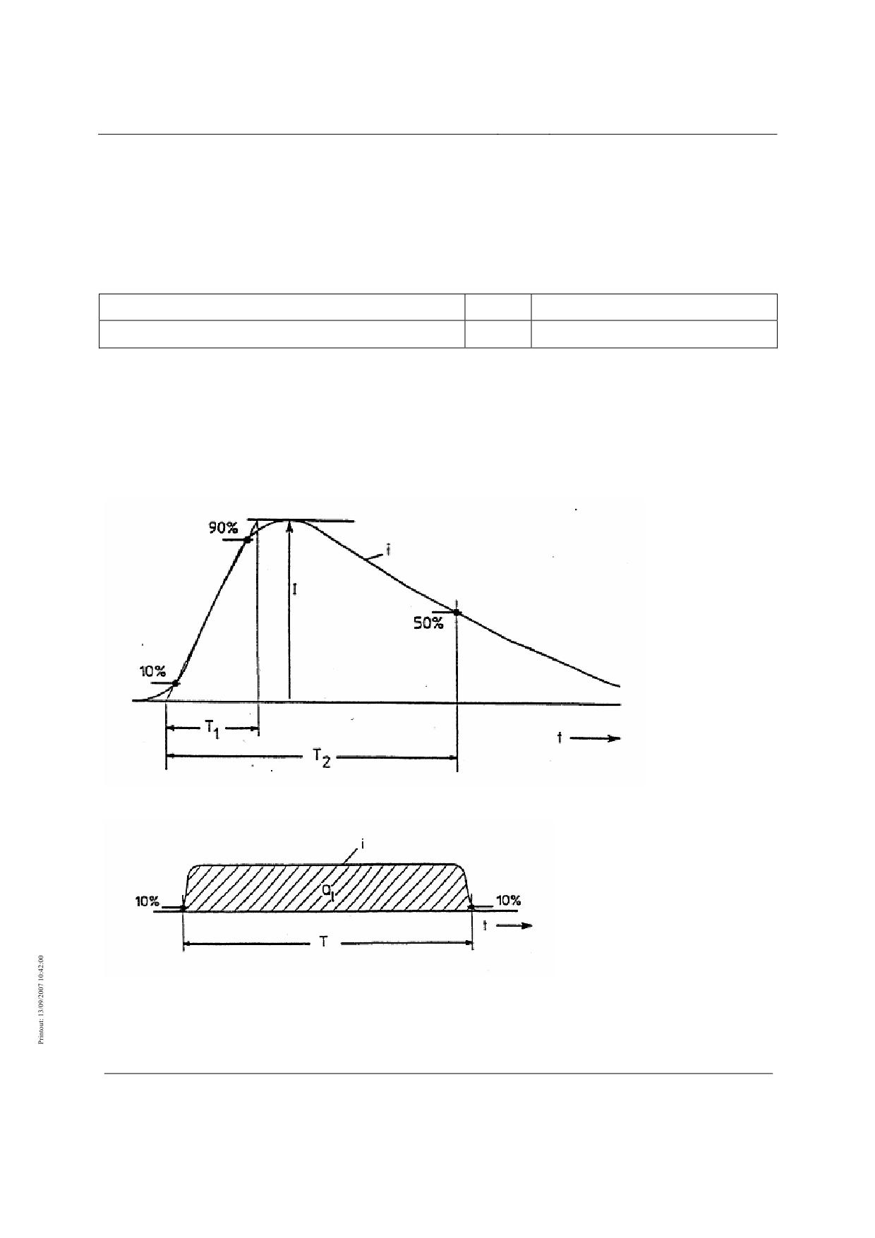
High-speed Maglev System
Maglev Technical
Committee
Design Principles
Complete System
Lightning
The MSB system must be protected from the actions of lightning specified below.
Lightning protection for structures must comply with local building regulations.
Frequency
Parameter
Value
Unit
Lightning strikes
20 *
strikes per square kilometre/year
*) This frequency of lightning strike is a meaningful figure with an adequate "safety interval" from the average "lightning charac-
teristics" observed in nature based on /WIESINGER/.
Table 35: Frequency of lightning strike
Intensity
according to /DIN EN 62305-1/ (VDE 0185-305-1)
Figure 34: First lightning discharge impulse and subsequent discharge impulse
Figure 35: Sustained discharge impulse
Title
High-speed Maglev System Design Principles
Complete System Annex 3 Environmental Conditions
Doc.No.:
67285
Version White pa-
Issue date
15.02.2007
Page 13
per
High-speed Maglev System
Maglev Technical
Committee
Design Principles
Complete System
Lightning current parameters of the first lightning discharge impulse
Parameter
Value
Unit
Peak current I
200
kA
Front time T1
10
µs
Time to half-value T2
350
µs
Charge of the transient discharge pulse Qs
100
C
Specific energy W/R
10
MJ/Ω
Table 36: Lightning current parameters of the first lightning discharge impulse (see Figure 34)
Lightning current parameters of the subsequent lightning discharge impulse
Parameter
Value
Unit
Peak current I
50
kA
Front time T1
0.25
µs
Time to half-value T2
100
µs
Mittlere Steilheit I/T1
200
kA/µs
Table 37: Lightning current parameters of the subsequent lightning discharge impulse (see Figure 34)
Lightning current parameters of the sustained lightning discharge impulse
Parameter
Value
Unit
Charge QI
200
C
Time T
0.5
s
Table 38: Lightning current parameters of the sustained lightning discharge impulse (see Figure 35)
Electrical and magnetic field strengths
Parameter
Value
Unit
dH/dt
3.2*1011
A/(m*s)
H
3.2*105
A/m
dE/dt
5.0 * 1011
V/(m*s)
E
5*105
V/m
Table 39: Distance from main lightning current path: 0.1 m
Title
High-speed Maglev System Design Principles
Complete System Annex 3 Environmental Conditions
Doc.No.:
67285
Version White pa-
Issue date
15.02.2007
Page 14
per
High-speed Maglev System
Maglev Technical
Committee
Design Principles
Complete System
Parameter
Value
Unit
dH/dt
3.2*1010
A/(m*s)
H
3.2*104
A/m
dE/dt
5.0 * 1011
V/(m*s)
E
5*105
V/m
Table 40: Distance from main lightning cur-
rent path: 1 mEarthquake
The local building regulations must be complied with in regard to earthquake safety when
designing structures for a specific project. For projects in Germany, and depending on the
specific project, the relevant earthquake strengths according to
/DIN 4149/, "Structures in German earthquake zones" must be determined and used as a basis
for structure design.
Immunity from electromagnetic interference
The immunity of MSB subsystems from interference must basically conform to European
standard DIN EN 50121 (Electromagnetic Compatibility; Railway Applications). The in-
tended performance characteristics of the MSB system must not be impaired by interference-
field strengths or conducted interference up to the limits given below.
Subsystems
Limits as per standard
Stationary installations and equipment for the drive and energy supply
DIN EN 50121-5
Vehicle
DIN EN 50121-3-1
appliances installed in vehicles
DIN EN 50121-3-2
Signalling and communications equipment incl. OCS radio
DIN EN 50121-4
Table 41: European standards for the immunity of MSB subsystems
Title
High-speed Maglev System Design Principles
Complete System Annex 3 Environmental Conditions
Doc.No.:
67285
Version White pa-
Issue date
15.02.2007
Page 15
per
High-speed Maglev System
Maglev Technical
Committee
Design Principles
Complete System
Specification of parameters for the secondary environment
This chapter lists the parameters for the secondary environment for the subsystems 'MSB ve-
hicle' and 'Installations'. It specifies the environmental spaces and
EMC/ lightning protection zones according to /DIN EN 62305-1/ (VDE 0185-305-1).
The following figures are based on operational experience with the secondary environment.
They reflect the current level of knowledge and should be confirmed project-specifically
and/or adjusted and verified as required. Adjusted values must be indicated in the project-
specific documentation (delivery specification, technical reports). The values in this document
apply in the absence of an explicit agreement.
The operational experience reflected in this document is based on MSB vehicles TR07 and
TR08 on the TVE and on the Shanghai Transrapid project.
The parameters for the EMC / lightning protection zones must allow for the radiation-related
electromagnetic effects due to lightning strike and to all types of field-related interference
effects, e.g. radio transmitters.
Secondary environment in MSB vehicle
The following requirements apply to all components and mount-on parts in and on the MSB
vehicle.
The environmental spaces of the MSB vehicle are shown in Figure 36 .
Title
High-speed Maglev System Design Principles
Complete System Annex 3 Environmental Conditions
Doc.No.:
67285
Version White pa-
Issue date
15.02.2007
Page 16
per
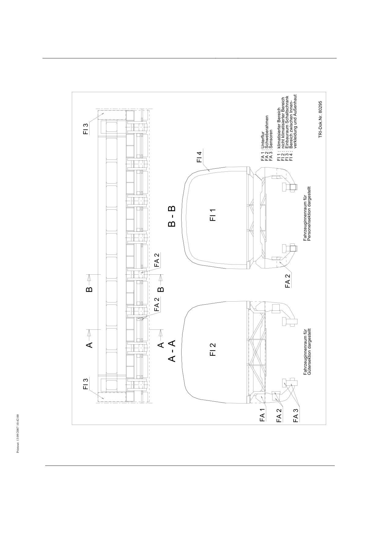
High-speed Maglev System
Maglev Technical
Committee
Design Principles
Complete System
Title
High-speed Maglev System Design Principles
Complete System Annex 3 Environmental Conditions
Doc.No.:
67285
Version White pa-
Issue date
15.02.2007
Page 17
per
High-speed Maglev System
Maglev Technical
Committee
Design Principles
Complete System
Figure 36: Environmental spaces of the MSB vehicle (typical arrangement)
Vehicle Exterior (FA):
•
Underfloor (FA1),
Space envelope for electrical/electronic modules, cable trunking, compressed air
supply equipment
•
Levitation frame (FA2),
- Space envelope for guide magnets
- Space envelope for brake magnets
- Space envelope for sensor electronics
- Panelling and mechanical structure levitation frame
•
Space envelope (FA3) for
- Levitation magnets
- Sensors.
Vehicle Interior (FI):
•
Airconditioned area (FI1),
Space envelope for service/communication/operating equipment
•
Non airconditioned area (FI2)
Space envelope for loading equipment
•
Control cubicle vehicle section (FI3)
Space envelope for control/safety equipment
•
Ceiling/wall behind panelling (FI4)
Space envelope for cables, lighting.
Vehicle - Exteriors (FA)
Exterior - Underfloor (FA1)
Parameter
Value
Unit
Temperature
Min. operating temperature for electronic components/batteries*)
-25
°C
Max. temperature rise compared with primary environment
10
K
Mean temperature rise compared with primary environment
5
K
*) When used with outside air temperature -25 °C to -40 °C it must be ensured that
• the components do not fall below min. operating temperature during train operations,
• parked vehicles are not allowed to cool to below -25 °C before startup and during preparation for train operation.
Parameter
Value
Unit
Title
High-speed Maglev System Design Principles
Complete System Annex 3 Environmental Conditions
Doc.No.:
67285
Version White pa-
Issue date
15.02.2007
Page 18
per
High-speed Maglev System
Maglev Technical
Committee
Design Principles
Complete System
Parameter
Value
Unit
Humidity (relative humidity)
Annual mean
≤90
%
Maximum value on 30 days spread over the year continuous
100
%
Condensation
yes
-
Parameter
Value
Unit
Pollution
Pollution degree according to /DIN EN 60664-1/
4
-
Degree of protection for internals according to /DIN EN 60529/
IP 65
-
Table 42: Temperature, humidity and pollution in FA1
Exterior - levitation frame (FA2)
Parameter
Value
Unit
Temperature
Min. operating temperature for electronic components/batteries*)
-25
°C
Max. temperature rise compared with primary environment
10
K
Mean temperature rise compared with primary environment
5
K
*) When used with outside air temperature <-25 °C to -40 °C it must be ensured that
• the components do not fall below min. operating temperature during train operations,
• parked vehicles are not allowed to cool to below -25 °C before startup and during preparation for train operation.
Parameter
Value
Unit
Humidity (relative humidity)
Annual mean
≤90
%
Maximum value on 30 days spread over the year continuous
100
%
Condensation
yes
-
Parameter
Value
Unit
Pollution
Pollution degree according to /DIN EN 60664-1/
4
-
Degree of protection for internals according to /DIN EN 60529/
IP 65
-
Table 43: Temperature, humidity and pollution in FA2
Title
High-speed Maglev System Design Principles
Complete System Annex 3 Environmental Conditions
Doc.No.:
67285
Version White pa-
Issue date
15.02.2007
Page 19
per
High-speed Maglev System
Maglev Technical
Committee
Design Principles
Complete System
Exterior - Space envelope for levitation magnets, sensors (FA3)
Parameter
Value
Unit
Temperature
Min. operating temperature for electronic components/batteries*)
-25
°C
max. Temperature rise compared with primary environment
25
K
Space envelope for sensor electronics in the magnet back
Max. temperature rise compared with primary environment
80
K
Space envelope for sensors in the magnet pole area on the side facing the winding
Mean temperature rise compared with primary environment
10
K
Space envelope for sensor electronics in the magnet back
Mean temperature rise compared with primary environment
30
K
Space envelope for sensors in the magnet pole area on the side facing the winding
*) When used with outside air temperature < -25 °C to -40 °C it must be ensured that
• the components do not fall below min. operating temperature during train operations,
• parked vehicles are not allowed to cool to below -25 °C before startup and during preparation for train operation.
Parameter
Value
Unit
Humidity (relative humidity)
Annual mean
≤90
%
Maximum value on 30 days spread over the year continuous
100
%
Condensation
yes
-
Parameter
Value
Unit
Pollution
Pollution degree according to /DIN EN 60664-1/
4
-
Degree of protection for internals according to /DIN EN 60529/
IP 65
-
Table 44: Temperature, humidity and pollution in FA3
Title
High-speed Maglev System Design Principles
Complete System Annex 3 Environmental Conditions
Doc.No.:
67285
Version White pa-
Issue date
15.02.2007
Page 20
per
High-speed Maglev System
Maglev Technical
Committee
Design Principles
Complete System
Vehicle - Interiors (FI)
Interior - Airconditioned area (FI1)
Parameter
Value
Unit
Temperature
Min. interior temperature *)
5
°C
Mean temperature in train operations (active air-conditioning)
**)
Max. temperature rise compared with primary environment in train operation (inactive air-
10
K
conditioning)
*) Vehicles parked during breaks in operation are air-conditioned such that the minimum interior temperature is maintained.
Maintenance with vehicle deactivation is carried out in a heated workshop. The minimum interior temperature following
maintenance is tested with the air-conditioning off according to the maintenance manual.
**) The mean room temperature follows the temperature curve shown in Annex A of /DIN EN 14750-1/ as a function of the
outside temperature.
Parameter
Value
Unit
Humidity (relative humidity)
Annual mean
≤65
%
Maximum value on 60 days spread over the year continuous
85
%
Condensation
no
-
Parameter
Value
Unit
Pollution
Pollution degree according to /DIN EN 60664-1/
2
-
Degree of protection according to /DIN EN 60529/
IP 54
-
Table 45: Temperature, humidity and pollution in FI1
Interior - Non airconditioned area (FI2)
Parameter
Value
Unit
Temperature
Min. interior temperature
-25
°C
Mean temperature in train operations (active air-conditioning)
------
-
Max. temperature rise compared with primary environment in train operation (inactive air-
10
K
conditioning)
Title
High-speed Maglev System Design Principles
Complete System Annex 3 Environmental Conditions
Doc.No.:
67285
Version White pa-
Issue date
15.02.2007
Page 21
per
High-speed Maglev System
Maglev Technical
Committee
Design Principles
Complete System
Parameter
Value
Unit
Humidity (relative humidity)
Annual mean
≤65
%
Maximum value on 60 days spread over the year continuous
85
%
Condensation
light condensation
-
Parameter
Value
Unit
Pollution
Pollution degree according to /DIN EN 60664-1/
2
-
Degree of protection according to /DIN EN 60529/
IP 54
-
Table 46: Temperature, humidity and pollution in FI2
Interior - Control cubicle vehicle section (FI3)
Parameter
Value
Unit
Temperature
Min. interior temperature *)
5
°C
Mean temperature in train operations (active air-conditioning)
25
°C
Max. temperature rise compared with primary environment in train operation (inactive air-
10
K
conditioning).**)
Max. temperature rise compared with primary environment in train operation (inactive air-
5
K
conditioning).**)
*) Vehicles parked during breaks in operation are air-conditioned such that the minimum interior temperature is maintained.
Maintenance with vehicle deactivation is carried out in a heated workshop. The minimum interior temperature following
maintenance is tested with the air-conditioning off according to the maintenance manual.
**) The interior temperature following maintenance is tested with the air-conditioning off according to the maintenance
manual.
***)When used with outside air temperature > 40 °C to 45 °C, the space envelope is ventilated with ambient air.
Parameter
Value
Unit
Humidity (relative atmospheric humidity)
Annual mean
≤65
%
Maximum value on 60 days spread over the year continuous
85
%
Condensation
no
-
Parameter
Value
Unit
Pollution
Title
High-speed Maglev System Design Principles
Complete System Annex 3 Environmental Conditions
Doc.No.:
67285
Version White pa-
Issue date
15.02.2007
Page 22
per
High-speed Maglev System
Maglev Technical
Committee
Design Principles
Complete System
Parameter
Value
Unit
Pollution degree according to /DIN EN 60664-1/
2
-
Degree of protection according to /DIN EN 60529/
IP 54
-
Table 47: Temperature, humidity and pollution in FI3
Interior - Ceiling/wall behind panelling (FI4)
Parameter
Value
Unit
Temperature
Min. interior temperature
- 25
°C
Mean temperature in train operations (active air-conditioning)
-----
-
Max. temperature rise compared with primary environment in train operation (inactive air-
15
K
conditioning)
Parameter
Value
Unit
Humidity (relative humidity)
Annual mean
≤65
%
Maximum value on 60 days spread over the year continuous
85
%
Condensation
no
-
Parameter
Value
Unit
Pollution
Pollution degree according to /DIN EN 60664-1/
2
-
Degree of protection according to /DIN EN 60529/
IP 54
-
Table 48: Temperature, humidity and pollution in FI4
Title
High-speed Maglev System Design Principles
Complete System Annex 3 Environmental Conditions
Doc.No.:
67285
Version White pa-
Issue date
15.02.2007
Page 23
per
High-speed Maglev System
Maglev Technical
Committee
Design Principles
Complete System
Mechanical excitation
The vehicle is excited to vibrate as its passes over the beams. The figures given below should
be regarded as actions on the components of the vehicle's exterior areas.
Source
Length
Max. frequency *)
Bay-wide guideway beams, beam precamber and longwave devia-
31 m
4.5 Hz
tion from the nominal position
Stator pack, fitting tolerance
1.032 m
135 Hz
Stator slot pitch
86 mm
1.6 kHz
*) The effect may be reduced if a maximum vehicle speed of less than 500 km/h is proposed in the application project con-
cerned.
Table 49: Source of vibration excitation at v = 500 km/h.
The actions due to vibration and shock are given in /MSB AG-FZ BEM/.
ESD Protection
The secondary environment in the vehicle can be electrostatically charged during noncontact
levitation relative to the stationary installations. From the safety aspect, the secondary envi-
ronment in the vehicle must be electrostatically discharged in such a way that the energy re-
maining after the discharge according to Section 17, Paragraph MbBO is less than 350 mJ.
EMC / Lightning protection
Definition of EMC / lightning protection zones
The EMC / lightning protection zones must be separated by electromagnetic shields.
Lines with cross the zone boundaries must be provided with protective circuits.
Four EMC / lightning protection zones are defined for the vehicle, and are characterised by
the following threats (see Figure 39) :
Zone 0A
•
Direct lightning strike possible.
•
Main and partial stroke current paths are inside the zone
•
Unattenuated field effect
Zone 0B
•
No direct lightning strike possible
•
No main and partial stroke current paths
•
Virtually unattenuated field effect
Zone 1
Title
High-speed Maglev System Design Principles
Complete System Annex 3 Environmental Conditions
Doc.No.:
67285
Version White pa-
Issue date
15.02.2007
Page 24
per
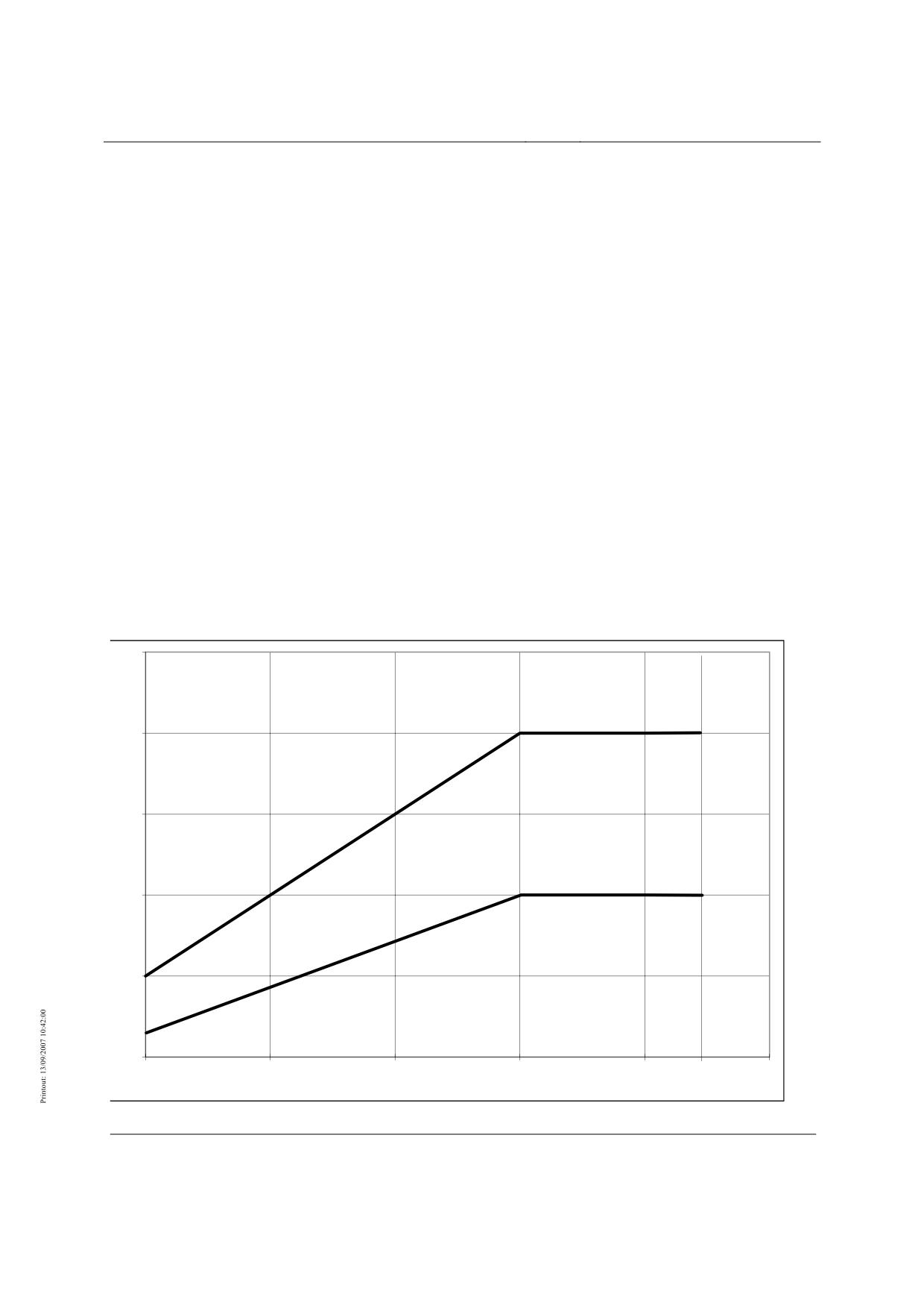
High-speed Maglev System
Maglev Technical
Committee
Design Principles
Complete System
•
No direct lightning strike possible
•
No main and partial stroke current paths
•
Field attenuation must satisfy the following minimum values:
-
for magnetic fields: as per Figure 37
-
for electrical fields: as per Figure 38
Zone 2
•
No direct lightning strike possible
•
No main and partial stroke current paths
•
Field attenuation must satisfy the following minimum values:
- for magnetic fields based on Zone 0A: as per Figure 37
- for magnetic fields based on Zone 1: as per Figure 37
- for electrical fields based on Zone 0A: as per Figure 38
- for electrical fields based on Zone 1: as per Figure 38
50
Dämpfung
(dB)
Zone 0→2
40
30
Zone 0→1
Zone 1→2
20
10
0
0,001
0,01
0,1
1
10
30
100
f (MHz)
Figure 37: Magnetic field attenuation
Title
High-speed Maglev System Design Principles
Complete System Annex 3 Environmental Conditions
Doc.No.:
67285
Version White pa-
Issue date
15.02.2007
Page 25
per
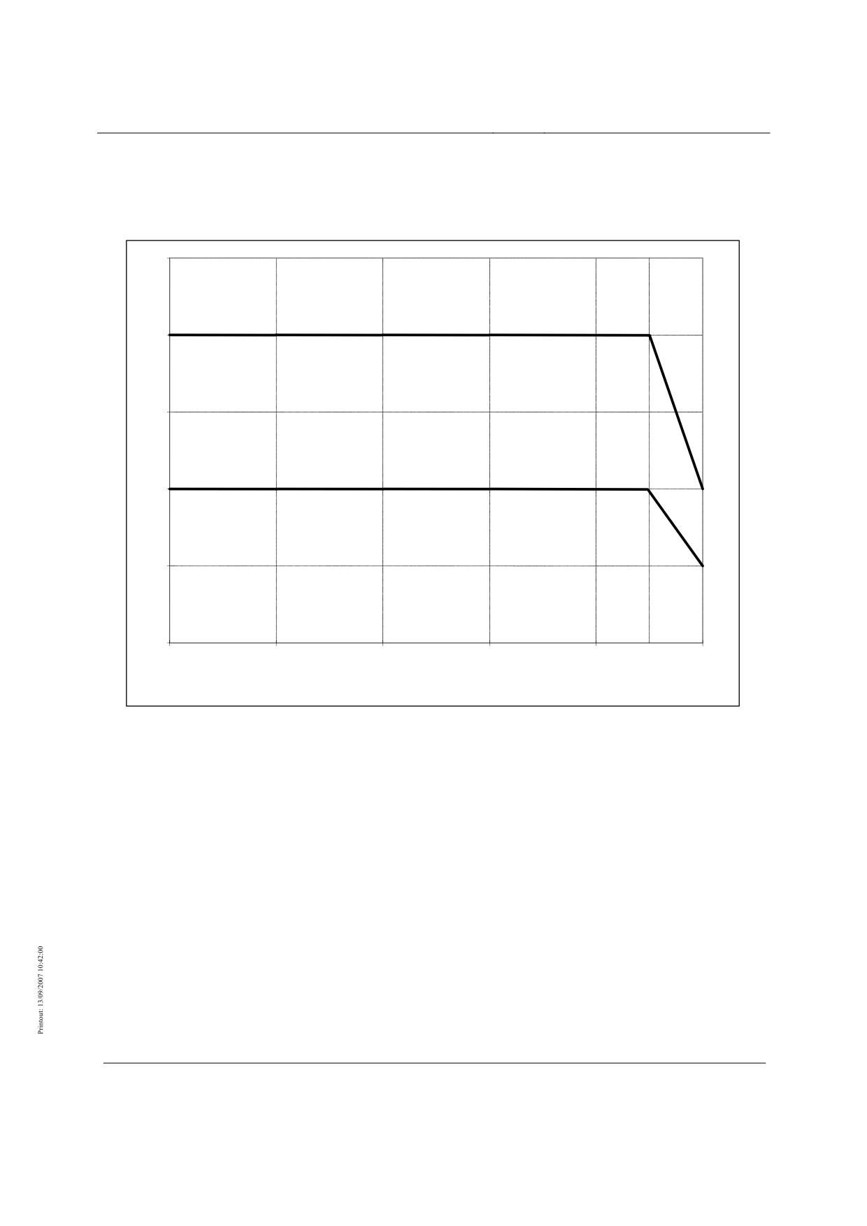
High-speed Maglev System
Maglev Technical
Committee
Design Principles
Complete System
50
Attenuation
(dB)
Zone 0->2
40
30
Zone 0->1
Zone 1->2
20
10
0
0,01
0,1
1
10
100
300
1000
Attenuation for f > 10 GHz: 0 dB
f (MHz)
Figure 38: Electrical field attenuation
Title
High-speed Maglev System Design Principles
Complete System Annex 3 Environmental Conditions
Doc.No.:
67285
Version White pa-
Issue date
15.02.2007
Page 26
per
High-speed Maglev System
Maglev Technical
Committee
Design Principles
Complete System
Assignment of the EMC / lightning protection zones to the space envelopes
The EMC / lightning protection zones are assigned to the space envelopes as follows:
Zone 0A
•
Exposed areas
•
Unshielded or unprotected underfloor area
Zone 0B
•
Car body interior, outside control cubicles and other shields
•
Underfloor areas protected from main and partial lightning currents
Zone 1
•
Shielded cable trunking
•
Interior of control cubicles inside the car body
•
Cores outside singly shielded cables
•
Housing interiors
Zone 2
Housing or cable shield interior. The housings and cables can be inside zones 0A, 0B or 1. The
required shield attenuation values must be achieved.
Title
High-speed Maglev System Design Principles
Complete System Annex 3 Environmental Conditions
Doc.No.:
67285
Version White pa-
Issue date
15.02.2007
Page 27
per
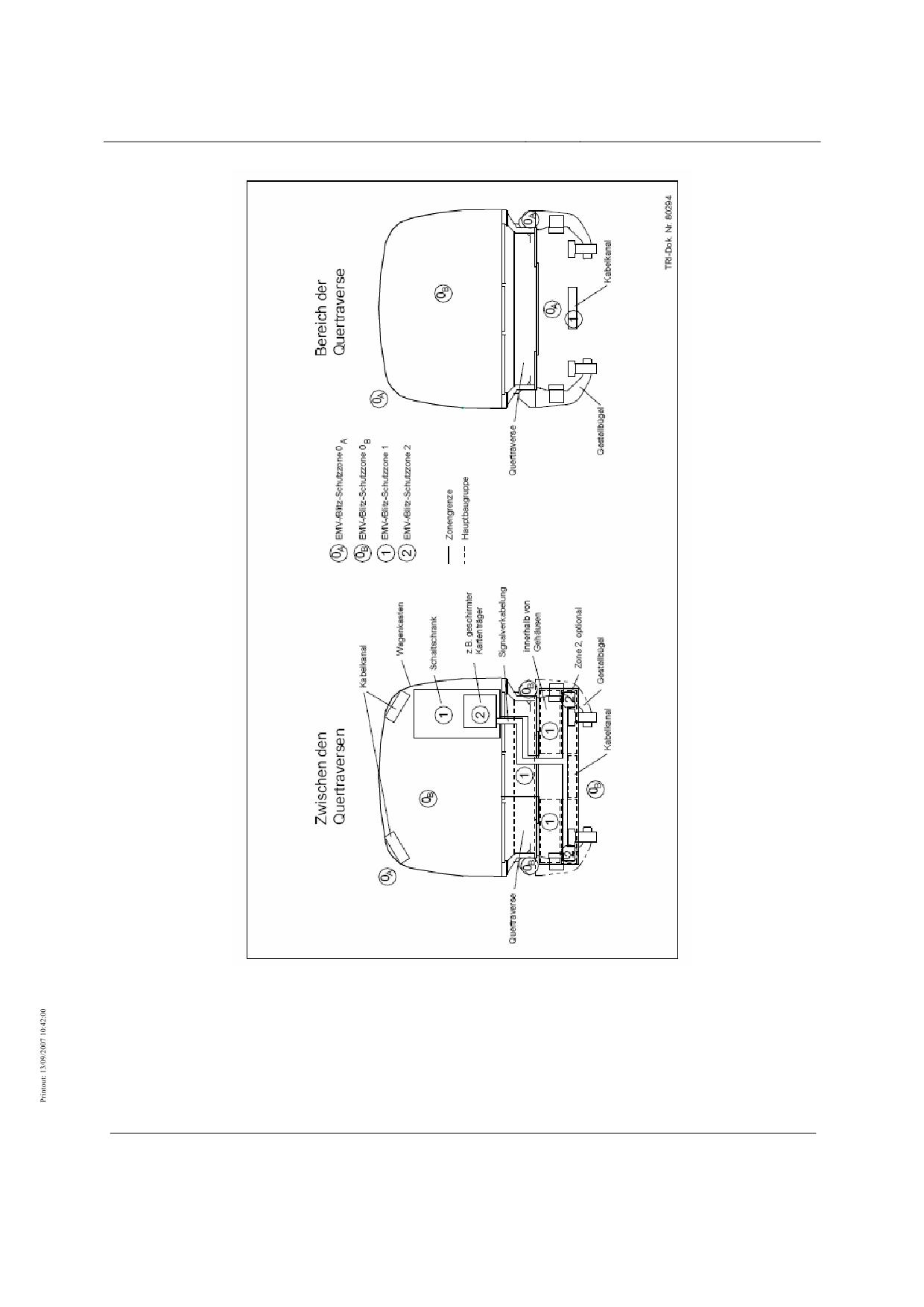
High-speed Maglev System
Maglev Technical
Committee
Design Principles
Complete System
Figure 39: EMC / lightning protection zones of the MSB vehicle
Title
High-speed Maglev System Design Principles
Complete System Annex 3 Environmental Conditions
Doc.No.:
67285
Version White pa-
Issue date
15.02.2007
Page 28
per
High-speed Maglev System
Maglev Technical
Committee
Design Principles
Complete System
Direct lightning strike - Threat levels for EMC / lightning protection zone 0A
At least two lightning flashover points per lightning impulse current, i.e. at least two lightning
current paths, must be expected in the event of a lightning strike into the vehicle.
The design of the lightning current-carrying equipotential bonding conductors, the shielding
and the electronic components is based on two partial stroke impulse currents with identical
lightning parameters.
This results in the following reduction factors compared with the lightning parameters given
in Chapter 0:
•
Lightning current peak value:
2
•
Lightning impulse charge:
2
•
Specific lightning energy:
4
For sustained current, the parameters are taken from Chapter 0.
A minimum distance of 0.1 m between the sink and the lightning current paths is assumed
when determining the limits of the lightning threat.
The minimum distance must be guaranteed by design engineering. With greater distances, the
threat values decrease proportional to the distance.
The maximum magnetic field threat values H or dH/dt are given according to /DIN EN
62305-4/ by the distance and the maximum lightning current values I or dI/dt.
H and I are derived from the first stroke, dH/dt and dI/dt from the subsequent strokes.
In the event of lightning strike according to / DIN EN 62305-4/ the electrical field E or dE/dt
is largely independent of distance at ranges of up to approx. 100 m from the strike point.
Lightning strike current
Lightning strike current (see Figure 35 and Figure 34):
Parameter
Value
Unit
Peak current I
100
kA
Charge of the transient discharge pulse Qs
50
C
Specific energy W/R
2.5
MJ/Ω
Table 50: Lightning current parameters of the first lightning discharge impulse
Parameter
Value
Unit
Peak current I
25
kA
Mean steepness I/T1
100
kA/µs
Table 51: Lightning current parameters of the subsequent discharge impulse
Title
High-speed Maglev System Design Principles
Complete System Annex 3 Environmental Conditions
Doc.No.:
67285
Version White pa-
Issue date
15.02.2007
Page 29
per