Design Principles High-speed Maglev System. Information (MSB, 2007) - page 6
Rapid Maglev System
Maglev Technical
Committee
Design Principles
Vehicle
•
In general, suitable materials data must satisfy the following requirements:
• Use of the fatigue strength data from recognised standards such as Eurocode 3 for steel mate-
rials and Eurocode 9 for aluminium materials.
• A preferred probability of survival of 97.5%, at least 95%.
• For materials not included in recognised standards, for which the values are established from
other reliable sources or from tests:
o A minimum number of 2 ⋅106 cycles with constant amplitude for steel materials, in
accordance with the endurance limit,
o A minimum number of 1 ⋅ 107 cycles with constant amplitude for aluminium materi-
als, in accordance with the fatigue limit.
• Classification of the designs (including the stress concentrations) in relation to stress concen-
trations.
• Data regarding capacity to withstand stresses obtained from small bar-shaped test objects
shall be checked on actual components with regard to their transferability.
• The stress-number curve, which is used to represent the fatigue behaviour of a material, must
show the influences named in Chapter 0 and the lower limit of the reproducibility defined pre-
viously.
•
The manufacturing and quality assurance procedures must highlight product qualities which
conform to the design data.
Uncertainties
•
The following influences produce uncertainties in the design and must be taken into ac-
count:
•
a) Dimensional tolerances
•
In general it is acceptable to use the nominal sizes of the components as a basis for the
calculations. Minimum dimensions have to be taken into account only if substantial reductions in
the thickness (because of wear etc.) are typical for operation of the component. Appropriate pro-
tection against corrosion is an integral part of the vehicle specification. The loss of material caused
by this can usually be disregarded.
•
b) Manufacturing process
•
The characteristics displayed by the material in an actual component may differ from those
deduced from test samples. Such differences can be traced back to variations in the manufacturing
process and to the workmanship, which cannot be detected in any practicable quality control pro-
cedure.
•
c) Accuracy of calculations
•
Every calculation procedure includes approximate values and simplifications. It is the manu-
facturer’s responsibility to apply the calculation procedure deliberately conservatively to the design.
Allowance must be made in the calculation procedure for the uncertainties described in a) and b)
by means of a factor. This “safety factor”, denoted by S, must be used when the calculated stress
is compared with the material limit value.
Title
High-speed Maglev System Design Principles
Vehicle, Part II, Dimensioning
Doc.No.:
67694
Version White
Issue date
15.02.2007
Page 17
paper
Rapid Maglev System
Maglev Technical
Committee
Design Principles
Vehicle
•
Title
High-speed Maglev System Design Principles
Vehicle, Part II, Dimensioning
Doc.No.:
67694
Version White
Issue date
15.02.2007
Page 18
paper
Rapid Maglev System
Maglev Technical
Committee
Design Principles
Vehicle
Demonstration of static strength and structural
stability
•
The following statements represent the minimum requirements for metallic materials and
must be taken into account. For non-metallic materials, the safety factors shall be agreed between
operator, manufacturer and supervisory authority.
Demonstration of load-bearing capacity
•
Calculation and testing (see Chapter 0) shall be used to demonstrate that no permanent
deformation or breakdown of the entire structure and/or individual parts will occur in the prescribed
load cases pursuant to Chapter 0 and the load case combinations in accordance with Chapter 0.
These requirements must be met by observing Chapter 0. If the structure is also restricted by the
conditions in Chapter 0 and Chapter 0, these must also be observed.
•
General stress demonstration
Yield or proof stress
•
If the strength of the structure is established exclusively by means of calculation, S1 must =
1.15 for metallic materials for each individual load case. For specific projects, S1 may be assumed
to be 1.0, if:
• the load cases are checked by tests or
• it can be shown that the uncertainties referred to in Chapter 0 are very small, or
• the superimposition of the load cases is demonstrated by means of calculation (see Chapter 0)
and
• there is sufficient operating experience. This must be substantiated in a comprehensible man-
ner.
•
Under the static load cases, as set out in Chapter 0, the ratio of the permissible to the cal-
culated stress must be greater than or equal to S1:
R
≥
S
1
σ
be
• Where:
R
is the material yield stress (Rel) or 0.2% - proof stress (Rp02), in N/mm².
σbe
is the calculated stress in N/mm²
•
When determining the stress levels of ductile materials, it is not necessary to take into ac-
count features which produce a local stress concentration. However, if the calculation includes
local stress concentrations, the theoretical stress may exceed the material yield stress or 0.2% -
Title
High-speed Maglev System Design Principles
Vehicle, Part II, Dimensioning
Doc.No.:
67694
Version White
Issue date
15.02.2007
Page 19
paper
Rapid Maglev System
Maglev Technical
Committee
Design Principles
Vehicle
proof stress. These ranges in local plastic deformation in connection with stress concentrations
must be so small that they do not cause any significant permanent deformation when the load is
removed.
Tensile strength
•
It is necessary to provide a safety margin between the maximum stress and the load-
bearing capability. This is achieved by incorporating a safety factor S2, where the ratio between
tensile strength and calculated stress must be greater than or equal to S2. (S2 includes the safety
factor S1)
R
m ≥
S
2
σ
be
• Where:
Rm is the tensile strength of the material in N/mm²,
σbe is the calculated stress in N/mm².
•
As a rule S2 is equal to 1.5, but the factor can be reduced if at least one of the following
conditions is met:
• there are alternative elements with sufficient load-bearing capacity;
• parts of the structure are designed in such a way that they fail in a controlled way;
• the calculations are so accurate that there is great confidence in the load-bearing capacity of
the critical structural areas.
•
The processing of stress concentrations as described in Chapter 0 is also applicable to this
case. The effect of stress concentrations must be taken into account in more detail for non-ductile,
if such stresses cannot be relieved by local plastic deformations.
•
A lower value for S2 must be laid down on a project-specific basis.
•
Stability failure
•
Local instability in the form of elastic buckling is permitted provided that alternative ele-
ments with sufficient load-bearing capacity are present and the yield or proof stress criterion is ob-
served.
•
The vehicle design must include a margin of safety against a global failure as a result of
instability. This is achieved by ensuring that the ratio between critical buckling or warping stress
and calculated stress is greater than or equal to S3 is:
σ
kKB
≥
S
3
σ
be
• Where:
σkKB is the critical buckling or warping stress in N/mm²,
σbe is the calculated stress in N/mm².
Title
High-speed Maglev System Design Principles
Vehicle, Part II, Dimensioning
Doc.No.:
67694
Version White
Issue date
15.02.2007
Page 20
paper
Rapid Maglev System
Maglev Technical
Committee
Design Principles
Vehicle
•
As a rule S3 is equal to 1.5. The factor can be reduced if the structure is designed so that it
fails in a controlled way. A lower value for S3 must be laid down on a project-specific basis.
•
Demonstration of rigidity
•
The rigidities of the vehicle assemblies must ensure the transmission of the specified loads
while observing the necessary loading gauges and preventing undue dynamic reactions.
•
The necessary rigidity may be set as maximum deformation under a prescribed load or as
minimum natural frequency. The requirements are applicable to the complete carriage body and/or
the magnetic running gear and also to individual components or assemblies.
•
The necessary body rigidity is fixed by means of the minimum natural frequency (bending
natural frequency).
•
The first bending natural frequency for the fully equipped carriage body assumed to be
freely levitated must be at least 7 Hz at an operating maximum speed of 500 km/h (experimental
value).
•
This value is obtained from the quotient of the vehicle maximum speed 500 km/h and the
guideway-support length 25 m plus reserve.
•
At an operating maximum speed of less than 500 km/h the natural frequency can be re-
duced to 500 km/h in linear proportion to the operating maximum speed.
•
At an operating maximum speed of 400 km/h a bending natural frequency of 5.6 Hz is suffi-
cient.
•
The requirement applies even where guideway supports with a support length > 25 m are
used.
•
The natural frequency must be demonstrated theoretically.
•
Requirements in excess of this must be laid down on a project-specific basis.
Title
High-speed Maglev System Design Principles
Vehicle, Part II, Dimensioning
Doc.No.:
67694
Version White
Issue date
15.02.2007
Page 21
paper
Rapid Maglev System
Maglev Technical
Committee
Design Principles
Vehicle
Demonstration of fatigue strength
•
The required service life or endurance limit of the structure in the prescribed load cases
pursuant to Chapter 0 and the load case combinations pursuant to Chapter 0 must be demon-
strated by means of calculations and testing (see Chapter 0). The proofs must comply with the
requirements in Chapter 0 and Chapter 0.
•
General
•
Account must be taken of the fact that the carriage body of the maglev vehicle as well as
the magnetic running gear are exposed to a great many dynamic loads of varying sizes during their
operating life.
•
The effect of these loads is most obvious in critical areas of the structure. Examples of such
areas are:
• sites where forces are introduced (including mounts for items of equipment),
• connections between components (e.g. welds, bolted connections),
• changes in geometry leading to stress concentrations (e.g. corners of doors and windows).
•
These critical areas must be identified. In this, the manufacturers’ experience must be taken
in to account in conjunction with the results of calculations and tests. Detailed investigations of the
local areas may be necessary.
•
Fatigue strength may be demonstrated using two different calculation methods:
• Demonstration of endurance limit (see Chapter 0),
• Demonstration of structural durability (see Chapter 0).
•
Account must be taken of the fact that the nature and quality of the available data affect the
choice of the procedures described in Chapter 0. The procedure applied must be laid down on a
project-specific basis.
•
If the investigated dynamic load cases in the fatigue calculation already include tolerances
for uncertainties, and provided that the minimum material characteristics as described in Chapter 0
are used, no further safety factor is necessary in this calculation.
•
Procedures to demonstrate fatigue behaviour experimentally or to check the calculation
results are described in Chapter 0.
Title
High-speed Maglev System Design Principles
Vehicle, Part II, Dimensioning
Doc.No.:
67694
Version White
Issue date
15.02.2007
Page 22
paper
Rapid Maglev System
Maglev Technical
Committee
Design Principles
Vehicle
Calculation method
Demonstration of endurance limit
•
This is permissible if the materials data show that there is a fatigue limit. The fatigue limit is
the stress at which no fatigue damage occurs provided that all dynamic load cycles remain below
it.
•
The necessary fatigue strength has been demonstrated if the stresses as a result of all
suitable combinations of steady load situations as laid down in Chapter 0 remain below the fatigue
limit.
Demonstration of structural durability
•
This is to be demonstrated if it is impractical to keep the stress level below the endurance
limit for all fundamental load combinations, or if no endurance limit can be laid down for the mate-
rial.
•
Each load case defined in Chapter 0 must be shown with regard to amplitude and number
of cycles by means of representative curves. Due account must be taken of concurrent load com-
binations. Damage as a result of each such case is then assessed again using a suitable material
S-N curve (stress-number curve). The total damage is determined in accordance with a proven
damage accumulation hypothesis (such as Palmgren-Miner, for example).
•
Load curves and combinations may be simplified provided that this produces results which
are reliable in appropriate respects.
Experimental demonstration of strength
•
The release procedure for the strength of vehicle assemblies provides for experimental
proof in addition to proof based on calculations:
• static tests,
• fatigue tests,
• track tests.
•
Usually, tests must be carried out to provide complete proof of strength and stability in ac-
cordance with the requirements of Chapter 0. It is not necessary to carry out tests if checked data
from earlier tests on similar structures are available and tests and calculations agree with each
other. If, however, there have been significant changes in the design or the operating conditions,
tests must be carried out.
•
The test programme must be laid down on a project-specific basis.
Title
High-speed Maglev System Design Principles
Vehicle, Part II, Dimensioning
Doc.No.:
67694
Version White
Issue date
15.02.2007
Page 23
paper
Rapid Maglev System
Maglev Technical
Committee
Design Principles
Vehicle
•
The specific aims of the static tests and fatigue tests are:
• to test the strength of the structure when this is exposed to the maximum load,
• to check that there is no permanent deformation after the maximum load has been removed,
• to demonstrate the strength of the structure in the operating load cases,
• to determine the dynamic behaviour of the structure.
•
If necessary, see above, the tests must include the following:
• static simulation of selected load cases,
• measurement of stresses by means of a strain gauge or other suitable procedure,
• measurement of structural deformation under loading,
• measurement of natural frequency behaviour.
•
The tested components and/or assemblies must be of the same kind and manufacture as
those subsequently used in operation. The test stand equipment must be properly and practicably
capable of applying the same loading to which the components and/or assemblies are exposed in
subsequent operation when they have been installed.
Static tests
•
The general purpose of static tests is to establish that components and/or assemblies are
not exposed to the risk of excessive deflections or permanent deformation in the case of excep-
tional loads.
•
Tests can be carried out to verify the proofs provided by means of calculations.
Generally, in the tests, strain controls are carried out in the areas of the components and/or as-
semblies subject to heavy stresses by means of resistance strain gauges, which measure in one di-
rection at points where the stress act in only one direction, but in at least two directions at all other
points.
•
The test programme for static tests must include the following information:
• size and position of the forces to be applied,
• combination of the forces to be applied,
• evaluation and interpretation procedure for the measured stresses,
• stress limit values,
• all further release criteria,
• measuring point plan for strain controls.
•
The measurements to be carried out in the entire test must be recorded in such a way as to
allow analysis of all measuring points in each load case, i.e. it must be ensured that at least the
minimum and maximum stress is determined.
•
The maximum value of the principal stress σmax and the minimum value of the principal
stress σmin define the mean value σm and the amplitude σa.
Title
High-speed Maglev System Design Principles
Vehicle, Part II, Dimensioning
Doc.No.:
67694
Version White
Issue date
15.02.2007
Page 24
paper
Rapid Maglev System
Maglev Technical
Committee
Design Principles
Vehicle
•
Mean values and amplitudes of the principal stress according to subsequent correlation
must be compared with the load-bearing capability of the material (e.g. fatigue limits) and evalu-
ated.
•
Where:
σm
is the mean value of the principal stress
σa
is the amplitude of the principal stress
σmax
is the maximum value of the principal stress
σmin
is the minimum value of the principal stress
Structural durability and endurance limit tests
•
Endurance tests consist of a main test and, possibly, additional specific tests.
•
The aim of the main test is to confirm that the strength of the assemblies and/or compo-
nents is sufficient with regard to the principle loads acting in them. Principal loads are loads which
trigger stresses in the entire structure.
•
Further tests may be carried out if necessary, particularly in the light of the results of calcu-
lations or static tests. These tests relate to forces which act only locally.
•
Fatigue tests must be carried out on vehicle parts of the primary power flux which are ex-
posed to dynamic loads, if the calculation includes uncertainties or if measurement results from the
operation of that detail type are not available.
•
Fatigue tests shall be carried out for components of the magnetic running gear (levitation
chassis and secondary suspension). For the frame of the carriage body, the mathematical model
must at least be verified by means of static tests.
•
The following test types may be used:
• Laboratory fatigue tests in which suitable load curves are applied to the vehicle assemblies for
the entire service life. No cracks which would adversely affect the safety or availability of the
structure may occur;
• Fatigue calculation on the basis of strain controls using the data from the test or from other
static tests;
• Fatigue calculation on the basis of strain controls using the data on representative operating
conditions.
•
The test programme for endurance tests must include the following information:
• forces to be applied and their position (static constant loads and dynamic parts),
• combination of the different forces, taking into account the phase relationships of different cy-
clical forces and their relative frequency,
• number of cycles (loadings),
• evaluation process,
Title
High-speed Maglev System Design Principles
Vehicle, Part II, Dimensioning
Doc.No.:
67694
Version White
Issue date
15.02.2007
Page 25
paper
Rapid Maglev System
Maglev Technical
Committee
Design Principles
Vehicle
• release criteria,
• measuring points plan for strain controls.
•
In general, for reasons of costs and time, only one assembly and/or one component is ex-
amined in the endurance test. As soon as it has been demonstrated that the specimen conforms to
the initial requirements, the test loads can be gradually increased. In this way it is possible to de-
termine the safety margin which covers the spread of the endurance limits.
•
For materials which have similar spreads in load-bearing capability, such as welds in steel
structures, the test procedure and the decision-making criterion in accordance with DIN EN 13749,
Annex G are used.
Track tests
•
Track tests must be carried out in order to demonstrate the operational requirements re-
garding the vehicle as well as the design loads and stresses in service.
•
As a rule, they are carried out as part of the commissioning of the vehicle and must be laid
down on a project-specific basis.
The programme for track tests must contain at least the following information:
• the vehicle to be used as well as the guideway-support types,
• description of the journeys to be undertaken (load cases, speeds, etc.),
• load conditions of the vehicle,
• assessment and interpretation procedures for the stresses,
• permissible load limits,
• all additional release criteria,
• measuring points plan for e.g. position measurements, acceleration measurements, power and
strain controls.
Title
High-speed Maglev System Design Principles
Vehicle, Part II, Dimensioning
Doc.No.:
67694
Version White
Issue date
15.02.2007
Page 26
paper
Rapid Maglev System
Maglev Technical
Committee
Design Principles
Vehicle
Load cases
•
This section sets out the load cases which are to be used when designing maglev vehicle
structures (carriage bodies, magnetic running gear, cowling parts etc.). It contains the minimum
load cases to be taken into account for demonstrating the load-bearing capacity and the fatigue
strength.
•
The targets indicated for the load cases represent minimum requirements. If an operator
considers higher values to be necessary to achieve safe operation, it must lay down the require-
ment. A lower value is acceptable for certain operating conditions or structural features if there are
technical grounds to prove this. In addition to the fixed load cases and all further requirements or
variations determined by the operator, it is the manufacturer’s responsibility to ensure that the
structure can withstand every other relevant static or dynamic load which occurs during the opera-
tion of the maglev vehicle.
•
The load cases for mechanical assemblies are classified in the following way according to
the probability of their occurrence:
• operation in failure-free state: continuous occurrence,
• exceptional loads (operation with failures and/or subject to exceptional actions): frequency of
occurrence 10 per annum per component of 100 per annum per section.
•
These values represent the current level of knowledge and must be verified by recording
evaluations of mechanical assemblies as part of maintenance. The demonstrations must be ad-
justed on the basis of these recordings, if necessary.
•
In accordance with MSB AG-GESAMTSYS, load cases resulting from malfunctions or fail-
ures, for which the probability of occurrence is less than 10-6 per annum, are not demonstrated.
A-loads (load cases for demonstration of fa-
tigue strength)
•
The data regarding A-loads apply with regard to demonstration of fatigue strength as dem-
onstration of endurance limit. For cases in which it is necessary or wiser to demonstrate structural
durability, load spectra based on the following information must be deduced.
Inertia forces
Vehicle weight
•
The possible loading states (vehicle deadweight, vehicle weight with payload) must be
taken into account.
•
The average vehicle weight is assessed for long-distance vehicles with restriction on ac-
cess (no standing room). Non-uniform load distributions as a result of payload fluctuations (non-
uniform distribution of the payload in x- and y-direction) are covered by the increase in the support
magnetic forces. An increase of 5% in the mean ultimate load per support magnet linkage is as-
sessed as the experimental value.
Title
High-speed Maglev System Design Principles
Vehicle, Part II, Dimensioning
Doc.No.:
67694
Version White
Issue date
15.02.2007
Page 27
paper
Rapid Maglev System
Maglev Technical
Committee
Design Principles
Vehicle
•
For vehicles such as airport links with a restriction on the number of seats and 320 kg/m² of
standing room area, the following typical load states serve as guideline values:
•
Case 1: 80 % of the journeys with all seats occupied and standing room density of one per-
son/m² (standard capacity utilisation)
•
Case 2: 15 % of the journeys with all seats occupied and standing room density of two per-
sons/m² (full use of capacity)
•
Case 3: 5 % of the journeys with all seats occupied and a maximum standing room density
of 320 kg/m² (maximum use of capacity).
•
The endurance limit must be demonstrated with the loading state ‘full use of capacity in
accordance with case 2. Accumulations of snow must be taken into account in accordance with
Chapter 0 on a project-specific basis.
•
In the case of operation with no restriction on access, passenger numbers must be re-
corded during operation (e.g. statistical evaluation) and, if necessary, appropriate measures must
be taken.
•
Unless otherwise agreed with the operator, the data for airport links are used for regional
transport.
•
Passing over concave and/or convex transition curves
•
Allowance must be made for the inertia forces when passing over the alignment elements
of concave/convex transition curves by assessment of the target for the maximum free vertical ac-
celeration.
•
Target:
•
azmax (convex transition curve) = -06 m/s²
azmax (concave transition curve) = 1.2 m/s²
Operational accumulations of snow
•
Loads resulting from accumulations of snow are not relevant for the carriage body and the
secondary suspension.
•
Accumulations of snow in cavities of the magnetic running gear, anticipated during opera-
tion, must be taken into account for the purposes of the demonstration. A covering of snow and ice
on the cowling of the magnetic running gear - inside and outside - may result in an increase in the
quantities in the magnetic running gear. Additional constraining forces caused by a reduction in the
maglev vehicle kinematics or a change in the maglev vehicle aerodynamics do not occur because
of the cowling of the magnetic running gear. If necessary, additional measures must be agreed
with the operator until project-specific operating experience is available.
•
The snow quantities to be assessed in operation for the load case of snow accumulation in
the maglev vehicle depend on the climatic zone of use and must be laid down on a project-specific
basis.
Title
High-speed Maglev System Design Principles
Vehicle, Part II, Dimensioning
Doc.No.:
67694
Version White
Issue date
15.02.2007
Page 28
paper
Rapid Maglev System
Maglev Technical
Committee
Design Principles
Vehicle
•
Unless otherwise agreed, the quantities are calculated on the basis of wet snow in accor-
dance with Table 5.
•
•
Acceleration / braking with propulsion alternating step process
•
The thrust forces are transmitted as quasi-static forces between long stator and support
magnet by interaction of support magnetic field and synchronous long stator current.
•
The inertia forces occurring during acceleration/braking with long stator propulsion must be
taken into account.
•
There are various, project-specific processes available for motor section switching: alternat-
ing step, three-step, leapfrog and time-shifting processes.
•
The following points must be taken into account:
• A location- and time-dependent thrust change, which is different on both sidewalls of the
maglev vehicle, acts on the maglev vehicle during motor section switching. In order to mini-
mise the onset of the thrust, the propulsion force on the active motor side can be increased.
There is no thrust on the opposite side at this time.
• To deduce the inertia forces, only the alternating step process at the time of section switching
is taken into account, as the stresses caused by the asymmetrical load introduction during the
section switching process are the greatest, and this covers all other processes.
• By agreement with the operator, the three-step process can also be taken into account on a
project-specific basis, as the loads are lower in this case as a result of the symmetrical intro-
duction of the force.
• The x-force to be assessed in the alternating step process corresponds to half of the thrust on
a maglev vehicle section and is applied on one vehicle side. The mean propulsion acceleration
axmitt is assessed for operation in failure-free state.
Specification (experimental value from TVE):
Acceleration:
axmitt = ± 0.8 m/s²
Thrust of the active motor side: 73 % of the propulsive force per section
Normal running with propulsion alternating step procedure
•
It is necessary to allow for the fact that forces from normal running are covered, see Chap-
ter 0. If structural durability is demonstrated instead of endurance limit, the vehicle thrust is to be
determined subject to the aerodynamic loads and the alignment for ax = 0 m/s².
•
Free lateral acceleration
•
The inertia forces from unbalanced lateral accelerations can be taken into account by as-
sessing the maximum operational free lateral acceleration.
•
That means that, for simplification, it is conservatively assumed that curves ≥ 1000 m are
taken exclusively with maximum free operational lateral acceleration.
•
Maximum value for cornering:
Title
High-speed Maglev System Design Principles
Vehicle, Part II, Dimensioning
Doc.No.:
67694
Version White
Issue date
15.02.2007
Page 29
paper
Rapid Maglev System
Maglev Technical
Committee
Design Principles
Vehicle
•
aymax = ± 1,5 m/s².
Dynamics of vehicle movement
•
The dynamic forces and moments (vehicle movement dynamics) resulting from the long-
wave positional tolerances of the functional surfaces of long stator and lateral guide rails must be
combined with the static reaction forces at the interfaces.
•
Alternating forces resulting from the magnetic action of the long stator nuts on the support
magnets and from short-wave positional tolerances or misalignments of stator packs and lateral
guide rails act as high-frequency noise and may be disregarded in the demonstrations. These al-
ternating forces must be taken into account when assessing the natural oscillation and resonance
behaviour and must be established as mechanical stress due to oscillation in the environmental
spaces of the maglev vehicle on a project-specific basis.
•
If the vehicle movement dynamics are taken into account via forces, no additional oscilla-
tory factor must be used.
Carriage body
•
An oscillatory factor of f = 1.0 ± 0.12 (verified value for carriage bodies with pneumatic sus-
pension) must be assessed as the target for dimensioning of the bodies.
Support/guidance system structure
•
Parts of the dynamic loads from vehicle movement dynamics must be added to the existing
constant load from propulsion/braking, support and guidance as quasi-static loads for each levita-
tion chassis on the most unfavourable basis. It is not necessary to allow for an additional adjust-
ment over and above an oscillatory factor.
•
Target for each linkage: (verified values for the structure of the support/guidance system):
•
∆FxTMA = ± 1.0 kN propulsion/braking (includes alternating step process)
•
∆FyFMA = ± 9.0 kN guidance
•
∆FzTMA = ± 4.0 kN support
Cowlings
•
The following acceleration values must be assessed as the targets for the external and
internal frame cowlings for the environmental space of the levitation frame (maximum values
from TVE experience):
•
ax = ± 2.0 m/s²
•
ay = ± 15 m/s²
•
az = ± 15 m/s²
•
•
Target for the nose cowling fixed to the frame:
•
ax = ± 8.m/s²
Title
High-speed Maglev System Design Principles
Vehicle, Part II, Dimensioning
Doc.No.:
67694
Version White
Issue date
15.02.2007
Page 30
paper
Rapid Maglev System
Maglev Technical
Committee
Design Principles
Vehicle
•
ay = ± 15.0 m/s²
•
az = +15.0 m/s² / -10.0 m/s²
Title
High-speed Maglev System Design Principles
Vehicle, Part II, Dimensioning
Doc.No.:
67694
Version White
Issue date
15.02.2007
Page 31
paper
Rapid Maglev System
Maglev Technical
Committee
Design Principles
Vehicle
•
Target for the carriage body transition plate:
•
ax = ± 3.5 m/s²
•
ay = ± 10.0 m/s²
•
az = ± 3.2 m/s²
•
For other vehicle configurations or suspension characteristics, estimates should be made
on the basis of adjusted oscillatory factors or dynamic loads and be verified when brought into ser-
vice.
•
Settled maglev vehicle
•
Lifting/settling at vFzg = 0 km/h at stations and service stops.
•
As a rule, loads for the settled vehicle are to be taken into account only for the magnetic
running gear (load reversal at the support magnet linkages). Operating loads can be disregarded
for the carriage bodies.
Constraining forces resulting from alignment
•
Account must be taken of the fact that return forces occur in the magnetic running gear
when horizontal radius RH is < 2000 m and guideway distortion α’ is greater than 0,1°/m.
•
Unless the project-specific parameters are different, the following alignment parameters
must be used for the demonstration:
•
Allowance may be made for the constraining forces which are relevant for operation by su-
perimposing the curve radius RH = 1000 m, the operationally aligned guideway gradient α = 120
and the guideway distortion α‘ = 0.1 0/m.
Initial stress caused by guidance magnet loads
•
If there are no project-specific data available, allowance must be made for an initial stress
force on the guidance magnet linkages.
•
Target:
•
FyFM0 = 4.5 kN (approx. 50% of the vehicle movement dynamics)
Aerodynamic loads
•
A distinction must be made when considering aerodynamic loads for the individual maglev
vehicle sections (carriage body nose, cylindrical area of the body, nose inlets, vehicle undercar-
riage, frame cowlings).
•
The following points must be taken into account:
• A location-dependent, non-uniform pressure distribution occurs on the surface of the nose
area in the leading and following-on section.
• In the cylindrical area of the maglev vehicle the pressure loads are to a large extent constant.
Title
High-speed Maglev System Design Principles
Vehicle, Part II, Dimensioning
Doc.No.:
67694
Version White
Issue date
15.02.2007
Page 32
paper
Rapid Maglev System
Maglev Technical
Committee
Design Principles
Vehicle
•
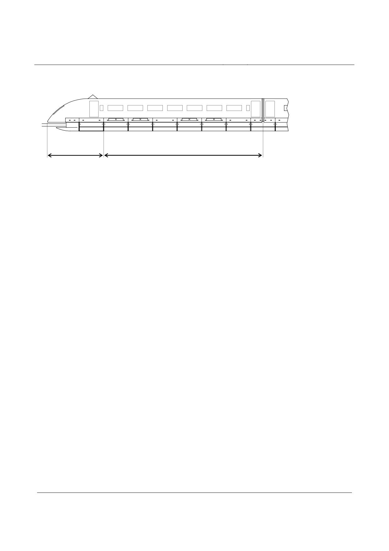
The end section can therefore be divided into two zones. The division in the zones can be
taken from the following illustration.
Zone 1
Zone 2
Figure 65: Zoning of the end section with regard to aerodynamic effects
•
Zone 1 comprises the nose area up to the transition to the cylindrical area of the body. The
flap of the external frame cowling at the transition from zone 1 to zone 2 is still completely attached
to zone 1. The middle sections are calculated with loads from zone 2.
•
If the aerodynamic loads are not indicated specifically for the project, data from worked ve-
hicles can be used if the shape of the head is comparable.
•
Unless agreed differently with the operator, the endurance limit demonstration can be pro-
vided at aerodynamic loads for the maximum vehicle speed and for the maximum tunnel speed.
Aerodynamic loads from relative wind
•
The speed-dependent local pressure distribution in the nose area (zone 1) and the constant
pressure distribution in the cylindrical area of the maglev vehicle (zone 2) must be taken into ac-
count as quasi-static loads acting on the surface of the maglev vehicle.
•
Loads from relative wind on the internal frame cowling and body undercarriage cowlings
may likewise be assessed as quasi-static loads.
•
Loads from relative wind include the effects of contrary wind. The wind-speed value to be
taken into account for A-loads, vW = 10 m/s, is lower than 10 % of the maximum vehicle speed.
•
Aerodynamic loads from crosswind
•
Unless different arrangements are made, the following targets are applicable (see also
MSB AG-Umwelt, Chapter 5.1.5):
•
A permanently acting, operational crosswind of vW = 10 m/s is taken to be the statically ap-
plied load.
•
On the basis of experience so far, the effective duration of a 10 min. mean value for wind >
10 m/s in a 10 m high guideway is 74 h per annum. That means that, for 99 % of the annual oper-
ating time, a wind of ≤ 10 m/s can be expected.
•
The overall height of the vehicle excluding aerial shall be assessed as the relevant height
for determining crosswind forces.
Title
High-speed Maglev System Design Principles
Vehicle, Part II, Dimensioning
Doc.No.:
67694
Version White
Issue date
15.02.2007
Page 33
paper
Rapid Maglev System
Maglev Technical
Committee
Design Principles
Vehicle
Forces on the carriage body
•
The body transition plate must be taken into account in the carriage body (see illustration in
MSB AG-FZ GEN.
•
The resulting force from the crosswind may be taken into account as a quasi-static area
force acting on the carriage body.
•
This load is dispersed by the support/guidance system.
•
Account must be taken of the fact that substantially higher aerodynamic loads are acting on
the leading nose section than on the following-on nose section in a crosswind and that these are
therefore determining for ascertaining the interface loads.
Forces on the external frame cowling
•
Account must be taken of the fact that the maximum loads act on the external frame cowl-
ing of zone 1. The resulting forces on the external frame cowling must, therefore, be deduced from
the pressure distribution in zone 1 and taken into account as a quasi-static load.
•
Account must be taken of the fact that the internal frame cowling and the body undercar-
riage are not subject to any relevant loads as a result of crosswind.
Aerodynamic loads from trains passing
•
The amplitudes of the pressure action on the bodies in free field shall be deduced as a
function of speed, track centre distance and the guideway lateral inclination.
•
The pressure amplitude acting at the vehicle speed and the projected guideway lateral in-
clination must be assumed for each passing of trains.
•
A corresponding function is included in MSB AG-GESAMTSYS.
•
If there are no specified data to the contrary available, this function may be used in the
demonstration. These data must be verified as part of the approval pursuant to MbBO.
•
For the global and local stresses on the structure or individual assemblies, the maximum
amplitude of the alternating pressure wave for the maximum vehicle speed vmax may be used for
the demonstration compared with operating loads.
•
The alternating pressure wave may be conservatively idealised as a step function. It may
be assumed that the loads act as quasi-static alternating quantities on a vehicle side, where two
alternating pressure waves have to be taken into account for trains passing (action of nose and
rear).
Title
High-speed Maglev System Design Principles
Vehicle, Part II, Dimensioning
Doc.No.:
67694
Version White
Issue date
15.02.2007
Page 34
paper
Rapid Maglev System
Maglev Technical
Committee
Design Principles
Vehicle
∆p
∆p
Pressure function
Real pressure
4 m
for demonstration
distribution
of ∆p
of ∆p
8 m
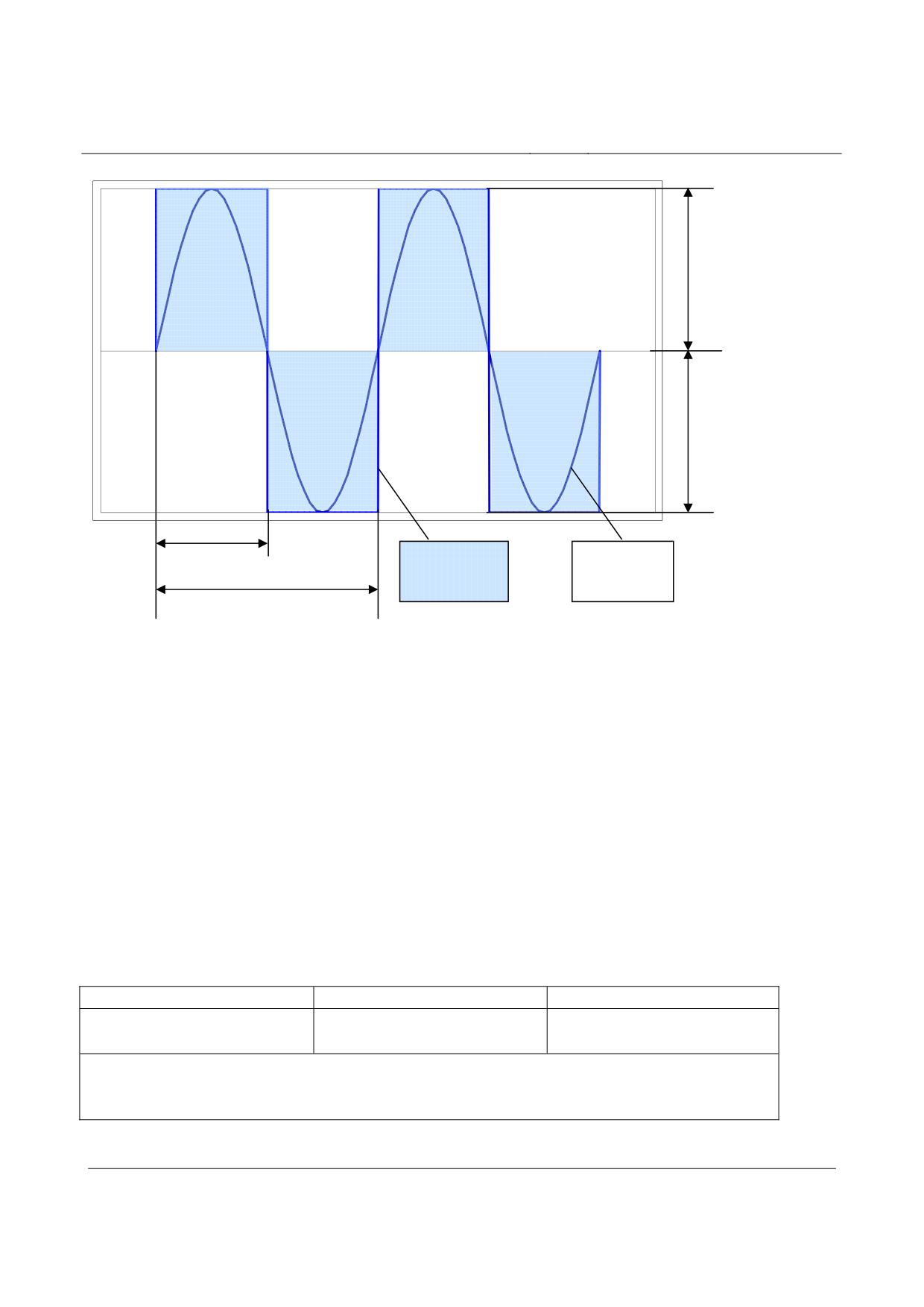
Figure 66: Alternating pressure wave nose/rear effect
•
The following points must be taken into account:
• The length of the pressure/drag load assessed in accordance with Figure 66 is 4 m in each
case, the two pressure/drag amplitudes 8 m.
• The alternating pressure waves run along the entire train.
•
The most unfavourable positions lengthwise along the vehicle must be taken into account
for the demonstration.
•
An oscillatory factor of 1.15 must be taken into account to allow for structural dynamics.
The assumptions must be verified as part of commissioning.
•
Additional loads caused by trains passing are not to be taken into account when dimension-
ing the guidance system.
•
The maximum vehicle speed vmax must be applied for the A-loads.
•
Example for deducing the alternating pressure amplitude in accordance with MSB AG-
GESAMTSYS:
Cylindrical part of body
Nose/rear of body
Trains passing
∆p = ± 1900 ⋅ 1.15
∆p = p(x, y, z) ± 1900 ⋅ 1.15
(vmax = 400 km/h)
∆p
Pressure change in [Pa]
p(x, y, z) Pressure at nose resulting from cp-distribution
Distance between side walls of passing vehicles 1.1 m
Guideway lateral inclination α = 12°
Table 70: Example of pressure amplitudes with trains passing
Title
High-speed Maglev System Design Principles
Vehicle, Part II, Dimensioning
Doc.No.:
67694
Version White
Issue date
15.02.2007
Page 35
paper
Rapid Maglev System
Maglev Technical
Committee
Design Principles
Vehicle
•
The frame cowlings can be treated in the same way as the cylindrical part of the carriage
body - unless otherwise agreed for specific projects.
Title
High-speed Maglev System Design Principles
Vehicle, Part II, Dimensioning
Doc.No.:
67694
Version White
Issue date
15.02.2007
Page 36
paper
Rapid Maglev System
Maglev Technical
Committee
Design Principles
Vehicle
Aerodynamic loads when passing through tunnels and open cuts
•
Compression stresses as a result of tunnel operation, with/without trains passing in single
and double tubes, must be taken into account on a project-specific basis.
•
Trains passing are only to be taken into account where there is appropriate alignment or
appropriate operating concepts.
•
For the A-loads, the scheduled vehicle speed vmax(Tunnel) is to be assessed in the tunnel.
•
As a result of the pressure difference between external and internal pressure, varying loads
occur on the pressure-tight carriage body. The amplitude and the number of relevant pressure
changes (loadings), which are dependent on vehicle speed, tunnel length, size of the obstruction
and the pressure tightness coefficient of the carriage body, must be ascertained on a project-
specific basis or may be taken from comparable applications.
•
The following must be taken into account:
•
The differential pressure between “pressure-tight” interior and external area of the vehicle is
dimensioning. In this case, the stationary maximum differential pressure is assessed for the maxi-
mum vehicle speed in the tunnel. The pressure/drag loads are applied as a constant value on the
total carriage body. The areas of the magnetic running gear which are not designed as pressure-
tight are not subject to any relevant stresses as a result of the pressure compensation.
•
The internal and external compressive values to be assessed must be determined and as-
sessed on a project-specific basis by means of suitable simulation and measurement processes.
•
The ∆p -values must be multiplied by a dynamic factor 1.15.
•
The compressive values for zone 1 must be superimposed with the pressure distribution
from steady travel outside the tunnel (free-field travel).
•
If project-specific pressure curves are available, these may be used.
•
To allow for passing through open cuts, the assessments for tunnel operation apply mutatis
mutandis.
•
The assumptions regarding tunnel operation and passing through open cuts must be veri-
fied by appropriate measurements on a project-specific basis as part of the approval.
•
Aerodynamic loads from lift
•
The aerodynamic lift of the carriage body acts in the opposite direction to the gravitational
force and can be disregarded in dimensioning of the body. The loads via the vehicle movement
dynamics, see Chapter 0, are recorded for the magnetic running gear.
Loads resulting from temperature changes
•
Allowance must be made for stresses on structures (e.g. carriage body) resulting from tem-
perature changes.
•
Effects of a possible temperature-dependent extension of long vehicles (more than 8 sec-
tions) on the propulsion thrust must be adjusted to the propulsion subsystem on a project-specific
basis.
Title
High-speed Maglev System Design Principles
Vehicle, Part II, Dimensioning
Doc.No.:
67694
Version White
Issue date
15.02.2007
Page 37
paper
Rapid Maglev System
Maglev Technical
Committee
Design Principles
Vehicle
S-loads in failure-free system state for demon-
stration of load-bearing capacity
•
In principle, the statements pursuant to Chapter 0 are applicable. Differences to allow
mainly for maximum operating loads are described below.
Inertia forces
Vehicle weight
•
The weight with 100 % payload (permissible vehicle weight, see Chapter 0) is to be taken
into account.
•
Passing over concave and/or convex transition curves
Allowance must be made for the inertia forces when passing over the alignment elements of con-
cave/convex transition curves with the accelerations pursuant to Chapter 0.
Maximum snow accumulations
•
The maximum snow accumulations to be expected in the cavities of the magnetic running
gear must be taken into account for the demonstration.
•
Appropriate measures must be taken to preclude the occurrence of inadmissible constrain-
ing forces inside the magnetic running gear through a reduction of the kinematics of the vehicle as
a result of snow covering. If necessary, provision must be made for operational measures in ex-
treme winter conditions, and the snow loads to be assessed and the supplementary measures
must be laid down until project-specific operating data are available.
•
The maximum snow quantities to be assessed for the load case of snow accumulation in
the vehicle depend on the climatic zone where the vehicle is used and must be laid down for the
specific project.
•
To demonstrate load-bearing capacity, the snow accumulations are determined by the
maximum possible volume of the magnetic running gear. The manufacturer must make realistic
assumptions regarding the possible volume and the snow density. If necessary, additional meas-
ures must be laid down until project-specific experience is available.
•
The snow densities indicated in Table 5 must be assessed to calculate the weight of snow.
Unless otherwise agreed, the quantities are to be calculated on the basis of wet snow.
Density of snow
Snow condition
[kg/m3]
New snow
100
Old snow
300
Title
High-speed Maglev System Design Principles
Vehicle, Part II, Dimensioning
Doc.No.:
67694
Version White
Issue date
15.02.2007
Page 38
paper
Rapid Maglev System
Maglev Technical
Committee
Design Principles
Vehicle
Wet snow
500
Table 5: Snow densities for different aggregation conditions
Acceleration / braking with propulsion alternating step process
•
As stated in Chapter 0, the alternating step process must be taken into account at the mo-
ment of motor section switching to demonstrate the acceleration/braking loads.
•
For operation in failure-free state with S-loads, the maximum propulsion acceleration pur-
suant to MSB AG-GESAMTSYS axmax must be assessed.
•
Maximum value: axmax = ± 1.5 m/s²
Target:
Thrust of the active motor side:
73 % of the propulsive force per section
•
Dynamic canting may be disregarded as the maximum thrust is used for calculation.
•
Normal running with propulsion alternating step procedure
•
Account must be taken of the fact that the inertia forces correspond to the A-loads from
Chapter 0 and are covered by the loads from Chapter 0 for demonstration of load-bearing capacity.
•
Free lateral acceleration
•
The maximum specified free lateral acceleration must be assessed to record the maximum
operational inertia forces from unbalanced lateral accelerations.
•
Maximum value for travel over points:
•
aymax = ± 2.0 m/s²
Title
High-speed Maglev System Design Principles
Vehicle, Part II, Dimensioning
Doc.No.:
67694
Version White
Issue date
15.02.2007
Page 39
paper
Rapid Maglev System
Maglev Technical
Committee
Design Principles
Vehicle
Dynamics of vehicle movement
Carriage body
•
The same oscillatory factors as for the A-loads in Chapter 0 are applied for dimensioning for
S-loads.
Magnetic running gear
•
Part of the dynamic loads from vehicle movement dynamics must be added to the existing
constant load from propulsion/braking, support and guidance as quasi-static loads for the magnetic
running gear. An additional adjustment over and above an oscillatory factor is not necessary.
•
Target (verified values for magnetic running gear TR08):
•
∆FxTMA = ± 1.2 kN propulsion/braking (includes alternating step process)
•
∆FyFMA = ± 9 kN guidance
•
∆FzTMA = ± 5 kN support
Cowlings
•
The same values as for the A-loads in Chapter 0 are applied for dimensioning of the exter-
nal and internal frame cowlings.
•
Target for the nose cowling fixed to the frame:
•
ax = ± 16.0 m/s²
•
ay = ± 25.0 m/s²
•
az = +21.0 m/s² / -10.0 m/s²
•
The same values as for the A-loads in Chapter 0 are assessed for dimensioning of the body
transition plate.
•
For other vehicle configurations or suspension characteristics, estimates must be made on
the basis of appropriately adjusted oscillatory factors or dynamic loads, analogous to Chapter 0,
and must be verified when brought into service.
•
Settled maglev vehicle
•
The same values as for the A-loads in 0 are assessed for dimensioning of the vehicle as-
semblies for S-loads. Demonstration of the inertia forces is covered by Chapter 0.
Title
High-speed Maglev System Design Principles
Vehicle, Part II, Dimensioning
Doc.No.:
67694
Version White
Issue date
15.02.2007
Page 40
paper
Rapid Maglev System
Maglev Technical
Committee
Design Principles
Vehicle
Constraining forces resulting from alignment
•
The two cases, “minimum horizontal radius without guideway lateral inclination” and “max.
guideway distortion”, must be taken into account to determine the maximum operating constraining
forces.
•
Unless other arrangements have been laid down between operator and manufacturer, the
following alignment parameters must be used for the demonstration:
•
Case 1: Minimum horizontal radius, radius RH = 350 m, α = 0° (vFzg = 100 km/h)
•
Case 2: Maximum guideway distortion, radius RH = RV = ∞, α‘ = 0.15°/m
Initial stress caused by guidance magnet loads
•
The same values as for the A-loads in Chapter 0 must be used for dimensioning of the ve-
hicle assemblies for S-loads.
Aerodynamic loads
•
The statements in Chapter 0 shall be applied mutatis mutandis with the following targets for
vehicle speed:
Line travel without tunnel:
vgrenz = vehicle limit speed
Tunnel operation
vgrenz(tunnel) = specified tunnel limit speed of the vehicle
•
Aerodynamic loads from relative wind
•
The statements in Chapter 0 are applicable. Unlike the A-loads, the vehicle limit speed
must be fixed.
Aerodynamic loads from crosswind
•
The statements in Chapter 0 are applicable.
•
The following load cases may be assessed to allow for the maximum operating loads; see
also MSB AG-Umwelt, Chapter 5.1.5:
•
Case 1: Continuous maximum crosswind of
vW = 37.3 m/s at vmitt
•
Case 2: Continuous maximum crosswind of vW = 37.3 m/s at vmax
•
Case 3: Continuous maximum crosswind of vW = 10.0 m/s at vmax
•
•
The 5-second gust of vW = 37.3 m/s at a height of 20 m, occurring every 10 years, is treated
as maximum load in the combinations of actions. Primary supporting frameworks, which are con-
Title
High-speed Maglev System Design Principles
Vehicle, Part II, Dimensioning
Doc.No.:
67694
Version White
Issue date
15.02.2007
Page 41
paper
Rapid Maglev System
Maglev Technical
Committee
Design Principles
Vehicle
structed with additional wind protection where appropriate, are provided for higher guideway sec-
tions.
•
In cases 2 and 3, the maximum vehicle speed is set as the vehicle speed.
•
Aerodynamic loads from trains passing
•
The statements in Chapter 0 are applicable.
•
Unlike the A-loads, the vehicle limit speed must be set in order to establish the pressure
alternating amplitude.
•
Aerodynamic loads from tunnel operation
•
The statements in Chapter 0 are applicable.
•
The demonstration must be at maximum static pressure difference during tunnel operation.
•
Maximum value: ∆p = ± 5500 Pa.
•
The demonstration must be at a pressure of ± 6000 Pa for the design (increased safety
factor 500 Pa).
•
Allowance for trains passing may result in higher pressure/drag loads. These must be laid
down on a project-specific basis.
•
Aerodynamic loads from lift
•
See Chapter 0.
Loads resulting from temperature changes
•
See Chapter 0.
S-loads during operation with failures for dem-
onstration of load-bearing capacity
•
Because there is little probability of occurrence of the exceptional load cases and the corre-
sponding load case combinations pursuant to Chapter 0, a safety factor of S = 1.0 can be used in
calculating for the demonstration.
Automated application of brakes with safety brake in the case
of brake control-circuit failure
•
During automated application of brakes with the safety brake (eddy current brake) and long
stator drive switched off, the vehicle settles steadily at the specified settling speed. The load case
Title
High-speed Maglev System Design Principles
Vehicle, Part II, Dimensioning
Doc.No.:
67694
Version White
Issue date
15.02.2007
Page 42
paper
Rapid Maglev System
Maglev Technical
Committee
Design Principles
Vehicle
pursuant to Chapter 0 relates to the state before settling. Loads from the state “settled vehicle” are
covered by specified special load cases.
•
The following effects must be taken into account for the load case represented by auto-
mated application of brakes with safety brake (eddy current brake) with failure of a brake circuit:
• Magnetic braking and accelerating forces as well as mechanical compressive and frictional
forces at the interface between braking magnet and lateral guide rails.
• Because of the non-uniform braking force of the individual maglev vehicle sections, the as-
sumed simultaneous failure of a brake control circuit also leads to a quasi-static transmission
of braking forces between the maglev vehicle sections.
• Non-uniform braking forces of the individual maglev vehicle sections also occur with local
guideway icing (different friction values of the braking magnets adjacent to the lateral guide
rails).
• The asymmetrical braking magnet-accelerating forces resulting from failure of a brake circuit
are dispersed on both sides of the guideway via the adjacent guidance control circuits.
•
Where applicable, account must be taken on a project-specific basis of superimposition of
the drive and eddy current brake and the superimposition of the eddy current and skid brake (set-
tled skid), if the probability of their occurring is > 10-6 per annum.
•
Allowance must be made for the following effects from the safety brake as the subject of
additional operating cases:
• slipping of the vehicle on support skids at a vehicle speed ≤ settling speed including stopping
shock (see Chapters 0, 0),
• non-uniform braking forces of the individual maglev vehicle sections as a result of local guide-
way icing (different friction values at the support skids where the vehicle slips, see Chapter 0).
•
The maximum decelerations occurring and the forces at the vehicle/guideway interface
(frictional forces) must be laid down and taken into account on a project-specific basis.
Failure of an on-board power supply
•
The load case covers operation with support/guidance control circuits switched off, either
separately or in combination. The failure of an on-board power supply causes the failure of individ-
ual support and guidance control circuits distributed over several levitation frames. The sup-
port/guidance control circuits are not adjacent.
•
The load case relates to the non-contact levitated vehicle, as support and guidance control
circuits are redundant and the support/guidance function is maintained. The loads at the interfaces
between support magnet and long stator and between guidance magnet and lateral guide rails are
transmitted in accordance with the target for the magnet control circuits.
•
Dual failures of adjacent support or guidance control circuits result in mechanical load dis-
persal via contact forces (see mechanical support, Chapter 0 or mechanical guidance, Chapter 0.
•
As a result of failure of a support control circuit, increased magnetic quasi-static and dy-
namic forces occur at the support magnet - long stator interface, and as a result of failure of a
guidance control circuit at the guidance magnet - lateral guide rail interface.
•
The moment of the failure up to and including partial venting of the pneumatic springs must
be taken into account for support control circuits.
Title
High-speed Maglev System Design Principles
Vehicle, Part II, Dimensioning
Doc.No.:
67694
Version White
Issue date
15.02.2007
Page 43
paper
Rapid Maglev System
Maglev Technical
Committee
Design Principles
Vehicle
•
The maximum decelerations occurring must be laid down and taken into account on a pro-
ject-specific basis.
Local mechanical guidance
•
In local mechanical guidance, the guidance loads are dispersed by mechanical contact of
the guidance magnets with the guideway lateral guide rails.
•
The mechanical compressive forces occurring at the interface between guidance magnet
and lateral guide rail must be taken into account.
•
With local mechanical guidance, a distinction must be made between:
• Running along onto the lateral guide rails as a result of failure of two adjacent guidance control
circuits and operation with mechanically guided levitation frame over a track to be set with the
operator on a project-specific basis.
• Running into local ice layers:
The maximum impact load must be set on a project-specific basis. If transferable data are
available from comparable structures, these may be set. Otherwise, the loads and stresses
must be ascertained by numerical simulation and/or experimental proof.
•
The maximum decelerations occurring and the forces at the vehicle-guideway interface
(frictional forces) must be laid down and taken into account with the operator on a project-specific
basis.
•
Running into layers of ice, the depths of which exceed the permissible values, must be
treated as collision with an obstacle. It is not necessary to refer to the loads occurring for dimen-
sioning with regard to load-bearing capacity, but it is necessary to ensure that no parts can break
off and leave the maglev vehicle.
•
The dynamic loads when running along on lateral guide rails must be taken into account
with an oscillatory coefficient of 1.15. Otherwise, dynamic forces on the guidance magnet, which
result from the positional tolerances and misalignments of the lateral guide rails during sliding and
act as high-frequency noise, may be disregarded.
•
The mechanical guidance function over the specified track and the magnitude of the oscilla-
tory factor may be demonstrated by means of experimental values with work vehicles. If it is not
possible to refer to experience with work vehicles and implemented slide combinations, trial inves-
tigations agreed with the operator must be carried out as part of the commissioning process.
Local mechanical support
•
In local mechanical support, the support forces at the support skids are dispersed by me-
chanical contact with the guideway sliding surface.
•
The mechanical forces occurring at the interface between support magnet and slide rail
must be taken into account.
•
With local mechanical support, a distinction must be made between:
• Settling of a support skid as a result of dual failure of two adjacent support control circuits
with/without venting of the pneumatic springs.
Afterwards, operation with mechanically supported levitation frame over a track agreed with
the operator on a project-specific basis, taking into account mechanical support with non, par-
Title
High-speed Maglev System Design Principles
Vehicle, Part II, Dimensioning
Doc.No.:
67694
Version White
Issue date
15.02.2007
Page 44
paper
Rapid Maglev System
Maglev Technical
Committee
Design Principles
Vehicle
tially or fully vented pneumatic springs.
The forces during controlled settling must be taken into account as static forces.
The impact factor for controlled settling of the vehicle is 1.0 (experimental value).
• Running of a support skid into a local, specified layer of ice:
The loads occurring in x- and z-direction are covered by the load case “uncontrolled settling”
(see 0) and are not demonstrated separately.
•
The maximum decelerations occurring and the forces at the vehicle/guideway interface
(frictional forces) must be laid down and taken into account on a project-specific basis.
•
Dynamic forces on the support skids resulting from the positional tolerances and misalign-
ments of the slide rail during sliding must be taken into account by means of an oscillatory factor of
1.15.
•
The mechanical support function of a levitation frame over the specified track and the oscil-
latory factor may be demonstrated by means of experimental values with work vehicles. If it is not
possible to refer on experience with work vehicles and implemented slide combinations, trial inves-
tigations agreed with the operator must be carried out as part of the commissioning process.
•
Target for the maximum permissible impact load:
•
Fz = 100 kN (corresponds to an impact factor of approx. 2).
•
Permissible ice-layer thicknesses must be fixed with the operator on a project- specific ba-
sis.
•
Running onto layers of ice, the depths of which exceed the permissible values, must be
treated as collision with an obstacle. If transferable data from comparable structures are available,
these may be applied. Otherwise, the loads and stresses must be determined by numerical simula-
tion and/or demonstrated experimentally. It is not necessary to refer to the loads occurring in a
collision for dimensioning with regard to load-bearing capacity.
Uncontrolled settling of support skids on one side
•
The load case relates to the uncontrolled settling of the maglev vehicle on one side onto the
support skids (of one side of a vehicle) as a result of a defective short circuit in a long stator motor
section. The magnetic feedback of the short circuit currents in the long stator lead to the support
control circuit being switched off, which is reversible.
•
The information in Chapter 0 must be used for the maximum impact load / support skid.
•
Target for friction coefficient:
µR = 0.3.
•
The maximum vehicle speed and the maximum support skid gap (at settling speed) must
be set for the simulation of uncontrolled settling on one side.
•
The support skid gap is made up of the static nominal value and a gap variance - resulting
from the control dynamics and the component tolerances.
•
A simultaneity factor of ψ = 0.8 must be set for the distribution of the individual skid gaps
over the vehicle.
Title
High-speed Maglev System Design Principles
Vehicle, Part II, Dimensioning
Doc.No.:
67694
Version White
Issue date
15.02.2007
Page 45
paper
Rapid Maglev System
Maglev Technical
Committee
Design Principles
Vehicle
Slipping/vibration
•
Slipping/vibration (asynchronous movement of the maglev vehicle with the magnetic long
stator-travelling field) causes increased magnetic, quasi-static and dynamic forces at the lift mag-
net/long stator interface.
•
Slipping /vibration must be taken into account as an action:
•
Target for magnetic forces:
FzTM = ± 2.5 kN/m
FxTM = ± 2.0 kN/m
•
Maximum frequency 538 Hz.
•
Demonstration of the load case is covered by demonstration of the alternating step process
pursuant to Chapter Error! Reference source not found..
•
•
Change in coefficient of friction in sliding, settled maglev vehi-
cle
•
Where changes occur in the coefficient of friction as a result of the environment (icing of
guideway, wet track etc.), allowance must be made for local differences in the coefficient of friction
in accordance with minimum or maximum coefficients of friction laid down on a project-specific
basis. The stresses initiated as a result of non-uniform distribution of interface loads must be taken
into account.
•
The different coefficients of friction at the support skids or at the braking magnet slide plates
result in non-uniform braking forces of the individual maglev vehicle sections.
•
Target for the change in coefficient of friction:
∆µR = 0.3.
Stopping shock from automated application of brakes with the
safety brake
•
Account must be taken of the stopping shock from slipping of the vehicle as a result of mov-
ing from sliding friction to static friction at the support skid / slide rail interface.
•
Target for sliding of support skid:
µR = 0.3.
•
Target for moving from sliding friction to static friction:
µTK-GL→Haft = 0.5.
•
The coefficient of friction covers the short-term peak forces of the stopping shock (approx -
200 ms).
Title
High-speed Maglev System Design Principles
Vehicle, Part II, Dimensioning
Doc.No.:
67694
Version White
Issue date
15.02.2007
Page 46
paper
Rapid Maglev System
Maglev Technical
Committee
Design Principles
Vehicle
Exceeding of payload in exceptional operating situations
•
Evacuation of a section in the case of fire must be taken to represent exceeding of the pay-
load in exceptional operating situations.
•
The passengers from the section to be evacuated are led to the adjacent section so that the
maximum payload is exceeded.
•
It may be assumed that the increased weight to be demonstrated is evenly distributed as a
result of the high density of people.
•
Target for maglev vehicles:
All seats occupied, standing room density 500 kg/m².
•
The weight targets must be agreed with the operator.
Exceeding the maximum track speed
•
The load case takes into account incorrect exceeding of maximum guideway speed as a
result of an error in propulsion control/control system.
•
The values for accelerations for cornering and passing through concave transition curves
must be increased to demonstrate the load case.
•
Target:
Increase in accelerations by 20 %.
•
The effect of the aerodynamic loads must be tested separately (load cases are not super-
imposed).
Exceeding of thrust as a result of propulsion failures
•
The following propulsion failures must be taken into account:
• Failure of the propulsion function of one guideway side (single-sided propulsion), introduction
of a load into the vehicle on the opposite side; this failure acts like propulsion via alternating
step process at the time of motor section switch.
• Exceeding the thrust through the long stator propulsion as a result of defective control of the
long stator current with uniform distribution to the left and right side of the vehicle.
Target: Thrust Fx = 250 kN per maglev vehicle (see MSB AG-GESAMTSYS, Chapter 9, No 7).
•
The yawing moment caused by the introduction of thrust on one side results in increased
magnetic force at the guidance magnet/lateral guide rail interface.
•
Because of the low probability of this occurring, a safety factor of S = 1.0 can be used for
calculating this load case.
Entering the shading coil
•
Braking of the maglev vehicle by entering areas of the long stator system with shading coil
at the end of the track.
Title
High-speed Maglev System Design Principles
Vehicle, Part II, Dimensioning
Doc.No.:
67694
Version White
Issue date
15.02.2007
Page 47
paper
Rapid Maglev System
Maglev Technical
Committee
Design Principles
Vehicle
•
The load case is covered by the other load cases for operation with failure or exceptional
action during propulsion and braking.
Position of the maglev vehicle with maximum lateral inclina-
tion
•
Allowance must be made for the load case of lifting / settling / standing of the maglev vehi-
cle according to worst-case stop on guideway with maximum lateral inclination.
•
The load case “position of the maglev vehicle at maximum wind speed of 37.3 m/s to be
taken into account (100-year maximum value)” is not considered. Loads from this action are not
relevant for dimensioning of the maglev vehicle structure, as experience shows that the impact
pressure caused by crosswinds for the 100-year maximum value at a height of 20 m in wind load
zone III is clearly below the static and dynamic design pressure of the carriage body. At a consid-
ered maglev vehicle height of 4.16 m, the force transmitted to the guideway every m from the im-
pact pressure on the magnetic running gear is lower than the force which is transmitted in the case
of a stationary maglev vehicle with 16° guideway lateral inclination at right angles to the longitudi-
nal axis.
•
The stopping forces in the x- and y-direction with longitudinally and laterally inclined guide-
way must be taken into account as static forces.
•
Maximum values: α = 16°
Elevation of maglev vehicle with frozen support skids
•
The load case must be demonstrated unless specific agreements concerning additional
measures have been reached with the operator (heated stop etc.).
•
The x- and z-loads when detaching a support skid which is frozen to the slide rail must be
taken into account in the demonstration of the components in the power flux.
•
Target for each support skid:
•
Tractive force in z-direction Fz = 50.0 kN,
•
Thrust in x-direction Fx = 25.0 kN.
Failure of nose pneumatic spring
•
During operation in failure-free state, the body is supported over all z-supports of the car-
riage body.
•
The loads at the z-support (pendulum) result from the pressure of the related pneumatic
spring. After venting of a pneumatic spring, in the case of partial venting reduced loads are dis-
persed by the associated pendulum, and in the case of full venting no loads are dispersed. The
differential forces are in part taken over by the other pendulums by rearrangement of the loads.
•
For dimensioning the body with mounting structure, the case of full venting at the nose
pneumatic springs (pendulum at the nose without power) must be demonstrated as the most unfa-
vourable load case.
Title
High-speed Maglev System Design Principles
Vehicle, Part II, Dimensioning
Doc.No.:
67694
Version White
Issue date
15.02.2007
Page 48
paper
Rapid Maglev System
Maglev Technical
Committee
Design Principles
Vehicle
Collision situations
•
The representative collision situations pursuant to MSB AG-GESAMTSYS or MSB AG-FZ
GEN must be established numerically.
•
The collision situations must be defined in the corresponding specifications of the assem-
blies; they are not relevant for dimensioning within the meaning of this document.
•
Separate documentary proof must be drawn up for the design of the assemblies relevant in
collisions, with the following objectives:
• compliance with the acceleration values in the body, as given in MSB AG-GESAMTSYS,
• no risk to tracking or to the stability of the guideway,
• continuation of the journey after a collision (no “blocking” of the vehicle), termination of pas-
senger travel and travel to maintenance for inspection and repair / replacement of the compo-
nents concerned,
• deformations of the body must be limited so that people are not trapped in the compartment,
• risk examination to assess components which fly off on a case-related basis.
Transport
•
Allowance is made for transport of the maglev vehicle without magnet modules, with static
ultimate/lifting loads and a proportion of the impact load during transport and assembly.
•
The following actions must be demonstrated for the vehicle configurations to be trans-
ported:
• Elevation with special lifting devices.
• To demonstrate elevation, a factor of 1.1 must be taken into account. The masses actually
elevated must be taken into account.
•
It must be possible for the vehicle structure to be transported without magnet modules (levi-
tation frame with support, guidance and braking magnets).
Title
High-speed Maglev System Design Principles
Vehicle, Part II, Dimensioning
Doc.No.:
67694
Version White
Issue date
15.02.2007
Page 49
paper
Rapid Maglev System
Maglev Technical
Committee
Design Principles
Vehicle
Superimposition of load cases
Demonstration of load-bearing capacity
•
The load cases from A-loads must be superimposed in accordance with Table 72 for the
demonstrations. Only the most unfavourable combinations have to be demonstrated.
Loads from running (S-loads)
Load case combinations S
1
2
3
4
5
6
Inertia forces from:
• Vehicle weight from Chapter 0
X
X
X
X
X
X
• Acceleration/braking with alternating step process with
X
X
X
X
X
axmax = 1.5 m/s²
• Passing over concave/convex transition curves with
X
X
X
X
X
azmax= + 1.2 m/s² / -0.6 m/s²
• Free lateral acceleration with
X
X
X
X
X
aymax = 2.0 m/s²
• Vehicle movement dynamics
X
X
X
X
• Settled maglev vehicle
X
Constraining forces resulting from alignment
• Radius RH = 350 m, α = 0 0 (vFzg ≤ 1 00 km/h)
X
• Radius RH = RV = ∞, α‘ = 0.15 0/m
X
X
X
Initial stress caused by guidance magnet loads
X
X
X
X
X
Aerodynamic loads from
• Relative wind vgrenz
X
X
• Relative wind vmax
X
• Crosswind
vW = 10.0 m/s
X
X
vW = 37.3 m/s
X
• Trains passing, pressure load at vgrenz
X
• Tunnel operation, pressure load at vgrenz (tunnel)
X
Temperature
X
X
X
X
X
X
Snow accumulation maglev vehicle (maximum)
X
X
X
X
X
X
Table 72: Superimposition of the S-loads from operation in failure-free state
•
Comments on Table 72:
Trains passing and crosswind are not superimposed because of the shadow effect.
The load case of normal running is not taken into account in the superimposition table, as the stres-
ses from the load cases of propulsion/braking with alternating step process are greater. At a running
speed of v < 100 km/h, the vehicle movement dynamics and the actions from aerodynamics are dis-
regarded because of the negligible effect. If relevant for the specific project, tunnel operation and
trains passing must be superimposed.
•
The following points must be taken into account:
• The load case combinations from operation in failure-free state in accordance with Table 72
may occur in combination with certain load cases in the event of failure or exceptional action
from Table 73.
Title
High-speed Maglev System Design Principles
Vehicle, Part II, Dimensioning
Doc.No.:
67694
Version White
Issue date
15.02.2007
Page 50
paper
Rapid Maglev System
Maglev Technical
Committee
Design Principles
Vehicle
• Because of the low probability of occurrence, superimposition is undertaken in that case with a
maximum of one of the load cases in the event of failure or exceptional action.
The superimpositions must be determined on a project-specific basis.
Loads in the event of failure and/or exceptional actions (S-loads)
-
Automated application of brakes with safety brake with asymmetric introduction of
braking force in the case of brake control-circuit failure
Failure of an on-board power supply
-
Local mechanical guidance
-
Local mechanical support
-
Uncontrolled settling of support skids on one side
-
Slipping/vibration
-
Change in coefficient of friction in sliding, settled maglev vehicle
-
Stopping shock from automated application of brakes
-
Exceeding of payload in exceptional operating situations (maximum vehicle weight in
accordance with Chapter 0)
-
Exceeding of maximum track speed
-
Exceeding of thrust as a result of propulsion failure
-
Entering the shading coil
-
Failure of nose pneumatic spring
-
Position of the maglev vehicle with lateral inclination α = 16°
-
Elevation of maglev vehicle with frozen support skids
-
Transport/assembly conditions: maglev vehicle equipped, without magnet modules
Table 73: S-loads from load cases in the event of failure and/or exceptional actions
•
•
Comments on Table 73:
•
The load case “position of the maglev vehicle with lateral inclination” with a maximum
marked-out lateral inclination of α = 16° is dimensioning for forces in y-direction only for the sup-
port skid and its fixing. The load case “elevation of maglev vehicle with frozen support skids” is
dimensioning in the x- and y-direction only for establishing the layers on the support skids. These
two combinations of actions must therefore taken into account separately, and not combined with
other actions.
•
The combination of the load case “change in coefficient of friction in sliding, settled maglev
vehicle” with a running speed of vmax does not occur as, in operation, the maglev vehicle is settled
only at vFzg < settling speed.
•
Similarly, the combination of the load case “change in coefficient of friction in sliding, settled
maglev vehicle” with tunnel operation does not occur, as it is assumed that the coefficient of friction
of the slide rail in the tunnel always remains within the usual tolerance.
Title
High-speed Maglev System Design Principles
Vehicle, Part II, Dimensioning
Doc.No.:
67694
Version White
Issue date
15.02.2007
Page 51
paper
Rapid Maglev System
Maglev Technical
Committee
Design Principles
Vehicle
Demonstration of fatigue strength
Demonstration of endurance limit
•
The load situations from A-loads must be superimposed in accordance with Table 74 for the
demonstrations. Only the most unfavourable combinations have to be demonstrated.
•
Loads from running (A-loads)
Load case combinations A
1
2
3
4
5
6
Inertia forces from:
• Total weight according to Chapter 0
X
X
X
X
X
X
• Acceleration / braking with alternating step process,
X
X
X
axmitt
• Normal running with alternating step process
X
X
• Passing over concave/convex transition curves with
X
X
X
X
X
azmax= + 1.2 m/s² / -0.6 m/s²
• Free lateral acceleration with
X
X
X
X
X
aymax = 1.5 m/s²
• Vehicle movement dynamics/oscillatory factor
X
X
X
X
X
• Settled maglev vehicle
X
Constraining forces resulting from alignment
• Radius RH = 1000 m, α = 12 0, α‘ = 0.1 0/m
X
X
X
X
Aerodynamic loads from
• Relative wind with vmax
X
X
X
X
• Crosswind vW = 10.0 m/s
X
X
• Trains passing, pressure load at vmax
X
X
• Tunnel operation, pressure load at vmax (Tunnel)
X
Snow accumulation, maglev vehicle (operational)
X
X
X
X
X
X
Table 74: Superimposition of the A-loads from operation in failure-free state
Comments on Table 74:
Trains passing and crosswind are not superimposed because of the shadow effect. The superim-
posing of A3 and A4 are covered by A1 and A2. If relevant for the specific project, tunnel operation
and trains passing must be superimposed.
Demonstration of structural durability
•
Load spectrums for the demonstration of structural durability must be agreed with the op-
erator or the licensing authority on the basis of project-specific data - unless transferable data from
earlier applications are available.
•
The demonstration must relate to the service life required by the operator. In this respect,
the vehicle service life and the life of the individual assemblies are not identical in all cases. For
assemblies which have a life shorter than the vehicle service life, maintenance measures must be
agreed in consultation with the operator (inspection intervals, repair and replacement measures,
Title
High-speed Maglev System Design Principles
Vehicle, Part II, Dimensioning
Doc.No.:
67694
Version White
Issue date
15.02.2007
Page 52
paper
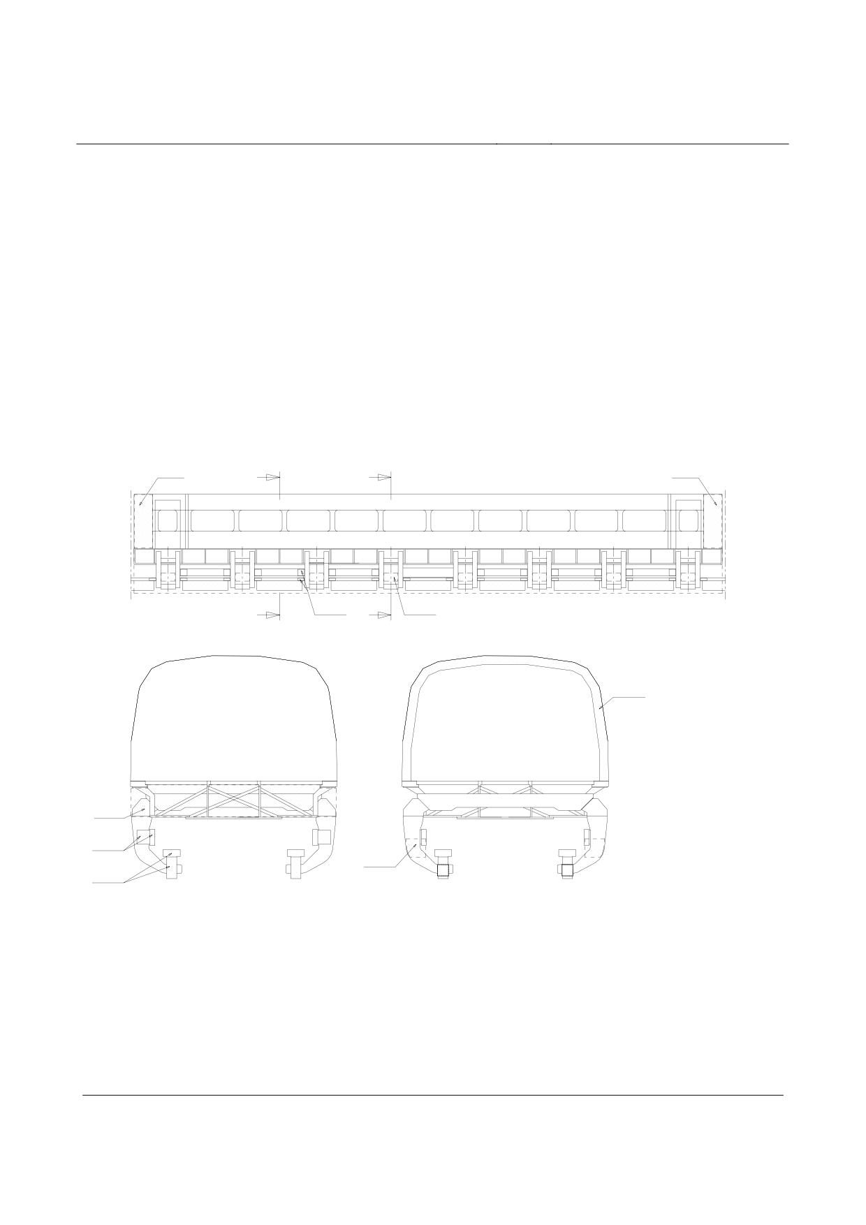
Rapid Maglev System
Maglev Technical
Committee
Design Principles
Vehicle
information regarding disclosure of defects). If required, additional demonstration methods such as
failure mode and effects analyses (FMEA) may be taken into consideration in order to assess
component failures.
Annex - Loading of mounting parts and attachments
•
The test criteria for qualification of the mounting parts and attachments with regard to load-
bearing capability against “vibration/shock” effects are set out below with reference to DIN EN
61373 and MSB AG-UMWELT.
Definition of environmental spaces
FI 3
FI 3
A
B
FA 2
FA 2
A
B
A - A
B - B
FI 4
FI 2
FI 1
FA 1
FA 1 :Unterflur
FA 2 :Schweberahmen
FA 3 :Sensoren
FA 2
FI 1 :
klimatisierter Bereich
FI 2 :
nicht klimatisierter Bereich
FA 2
FI 3 :
Einbauraum Schaltschrank
FI 4 :
Bereich zwischen Innen-
FA 3
verkleidung und Außenhaut
Fahrzeuginnenraum für
Fahrzeuginnenraum für
Gütersektion dargestellt
Personensektion dargestellt
Figure 67: Environmental spaces from MSB AG-UMWELT
Fl 2
Fl 1
FA 1: under-floor
Vehicle interior shown
Vehicle interior shown
FA 2: levitation frame
for goods section
for passenger section
FA 3: sensors
Fl 1: air-conditioned area
Fl 2: non-air-conditioned area
Fl 3: switchgear clearance
Fl 4: Area between internal cladding
Title
High-speed Maglev System Design Principles
Vehicle, Part II, Dimensioning
Doc.No.:
67694
Version White
Issue date
15.02.2007
Page 53
paper
Rapid Maglev System
Maglev Technical
Committee
Design Principles
Vehicle
and outer skin
Title
High-speed Maglev System Design Principles
Vehicle, Part II, Dimensioning
Doc.No.:
67694
Version White
Issue date
15.02.2007
Page 54
paper
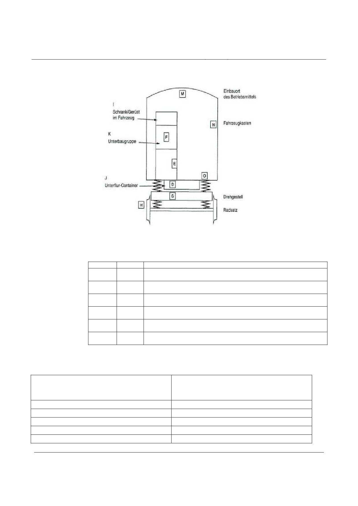
Rapid Maglev System
Maglev Technical
Committee
Design Principles
Vehicle
I = cabinet/housing in the vehicle
M = installation place for equipment
K = sub-assembly
N = vehicle body
J = under-floor container
G = bogie
H = wheel set
Category
Position
Description of the installation place of the equipment
1
M, N, O,
Describes components/equipment which are fixed on or in the vehicle
Class A
I and J
body
1
D
Describes components/equipment, installed in a container, which is fixed
Class B
in the underframe to the vehicle body
1
K and E
Describes components/equipment, installed in a large cabinet/ housing,
Class B
which is fixed to the vehicle body
1
F
Describes components/equipment as a part of a subassembly, installed in
Class B
a cabinet/housing, which is fixed to the vehicle body
2
G
Casings, components/equipment, which are fixed to the bogie of a rail
vehicle
3
H
Casings, components/equipment, which are fixed to the wheel set of a rail
vehicle
Figure 68: Environmental spaces (categories) from DIN EN 61373
:
Maglev - Design Principles Overall System,
DIN EN 61373
Annex 3 MAGLEV - Environmental spaces
MSB AG-UMWELT
Environmental space
Category
FA 3
Category 3
FA 2
Category 2
FA 1
Category 1 Class B
FI 1 - FI 4
Category 1 Class A or Class B
Title
High-speed Maglev System Design Principles
Vehicle, Part II, Dimensioning
Doc.No.:
67694
Version White
Issue date
15.02.2007
Page 55
paper
Rapid Maglev System
Maglev Technical
Committee
Design Principles
Vehicle
Table 75: Comparison of the clearances
Test levels
•
The relevant actions for loading of the mounting parts and attachments by “vibration/shock”
are taken from measurements on vehicles TR07, TR08 and Transrapid Shanghai.
•
The actions determined on the basis of the results of these measurements are shown in
Table 76. The values in Table 76 must be referred to as test levels for functional testing of the as-
semblies. The test levels and test duration for the life testing must be deduced on the basis of DIN
EN 61373.
•
The values given in the following table must be verified for modified components or configu-
rations of the vehicle and guideway engineering.
•
Environ-
Direction
Acceleration
Test level of the
Test du-
Test fre-
mental
level (FRTL-
life testing as ac-
ration
quency
space cate-
level pursuant
tual value
gory
to
[h]
DIN EN 61373)
[m/s2]
[m/s2]
[Hz]
FA 1
lengthwise (x)
0.20
1.6
5
10 - 150
Cat 1/ Cl B
transverse (y)
0.45
3.6
5
vertical (z)
0.75
6.0
5
FA 2
lengthwise (x) 1)
1.0
8
5
10 - 1600
Cat 2
transverse (y) 1)
4.0
32
5
vertical (z)1)
5.0
40
5
FA 3
lengthwise (x) 1)
25.0
100
73
10 - 1600
Cat 3
transverse (y) 1)
30.0
100
152
vertical (z) 1)
30.0
100
152
FI 1-4
lengthwise (x)
0.20
1.6
5
10 -150
Cat 1/ Cl A
transverse (y)
0.45
3.6
5
Cat 1/ Cl B
vertical (z)
0.75
6.0
5
Peak acceleration
Shock
duration
[m/s²]
[ms]
vertical
300
11
All
transverse
300
11
lengthwise
300
11
1)
Test frequency for all support and/or guidance magnets in accordance with DIN EN 61373
Table 76: Test levels for vibration/shock
Title
High-speed Maglev System Design Principles
Vehicle, Part II, Dimensioning
Doc.No.:
67694
Version White
Issue date
15.02.2007
Page 56
paper
High-speed Maglev system
Maglev Technical Committee
Design principles
Vehicle
High-speed Maglev System
Design Principles
Vehicle
Part III
Kinematic Gauge
The author retains the copyright in this document and all attachments.
All rights reserved
Title
High-speed Maglev system design principles
Vehicle, Part III, Kinematic Gauge
Document
67650
Version
White Paper Issue date
15.02.2007
Page 1
no.:
High-speed Maglev system
Maglev Technical Committee
Design principles
Vehicle
Distributor:
This document was released for publication by the Vehicle Technical Committee.
Title
High-speed Maglev system design principles
Vehicle, Part III, Kinematic Gauge
Document
67650
Version
White Paper Issue date
15.02.2007
Page 2
no.:
High-speed Maglev system
Maglev Technical Committee
Design principles
Vehicle
Summary of amendments
Date of release: 15.02.2007; White Paper, Vehicle Technical Committee.
Title
High-speed Maglev system design principles
Vehicle, Part III, Kinematic Gauge
Document
67650
Version
White Paper Issue date
15.02.2007
Page 3
no.:
High-speed Maglev system
Maglev Technical Committee
Design principles
Vehicle
Table of Contents
1
Distributor:
Error! Bookmark not defined.
2
Summary of amendments
Error! Bookmark not defined.
3
Table of contents
4
4
General
6
4.1
Objective and scope
6
4.2
High-speed Maglev System - Design Principles 7
4.3
Abbreviations and definitions
8
4.4
Acts, Orders, Standards and Guidelines 8
4.5
Identification and compulsory nature of the requirements
8
4.6
References
8
5
Definitions (subsystem-specific)
9
5.1
Coordinate system
9
5.2
Concepts
11
5.3
Abbreviations 12
5.4
Definitions and terminology
15
5.5
Alignment parameters
18
5.6
Loading gauge
18
6
Demonstration procedure
21
7
Kinematic degrees of freedom of carriage body
23
7.1
Rolling of carriage body 23
7.1.1
Concepts regarding carriage body rolling
23
7.1.2
Rolling load cases to be examined
25
7.2
Z-displacements / pitching of carriage body
26
7.2.1
Concepts regarding carriage body z-displacements / pitching
26
7.2.2
Z-displacement / pitching load cases to be examined Error! Bookmark not defined.
7.3
Y-displacement / yawing of carriage body 29
7.3.1
Concepts regarding carriage body y-displacements / yawing
29
7.3.2
Y-displacement / yawing load cases to be examined
31
8
Kinematics between levitation chassis and guideway
32
8.1
Kinematic degrees of freedom of levitation chassis
32
8.2
Displacements of levitation chassis
33
8.2.1
Support gap and support skid gap
33
Title
High-speed Maglev system design principles
Vehicle, Part III, Kinematic Gauge
Document
67650
Version
White Paper Issue date
15.02.2007
Page 4
no.:
High-speed Maglev system
Maglev Technical Committee
Design principles
Vehicle
8.2.2 Guidance gap
35
8.3
Torsions of the levitation chassis
36
9
Demonstration of the vehicle kinematic gauge
37
9.1
Guidance cross-sections
37
9.2
Load cases / geometric situations to be considered
38
9.2.1 Operational load cases 38
9.2.2 Specific operational cases
41
10
Annex (for information purposes)
42
10.1
Deduction of the kinematic degrees of freedom of carriage body 42
10.1.1 Roll angle of carriage body
42
10.1.2 Z-displacements and pitch angle of carriage body
43
10.1.3 Y-displacements and yaw angle of carriage body
47
10.2
Guidance gap correction for curved guideway
48
LIST OF ILLUSTRATIONS
Figure 1: Vehicle coordinate system 10
Figure 2: Side view and cross-section of a vehicle (diagrammatic representation)
15
Figure 3: Relevant geometric definitions of guideway dimensions 16
Figure 4: Characteristic quantities for the kinematics of maglev vehicles
17
Figure 5: Loading gauge of maglev vehicles - straight track 19
Figure 6: Loading gauge of maglev vehicles - curve radius 350 m to 3500 m
20
Figure 7: Vehicle kinematics - rolling of carriage body
24
Figure 8: Vehicle kinematics - z-displacements / pitching of carriage body
27
Figure 9: Vehicle kinematics - y-displacements / yawing of carriage body
30
Figure 10: Vehicle kinematics - gap balance support (z-direction) 33
Figure 11: Vehicle kinematics - gap balance guidance (y-direction)
35
Figure 12: Positioning of vehicle on guideway
37
Figure 13: Guidance gap correction for cornering
49
LIST OF TABLES
Table 1: Operating cases for vehicle kinematics
38
Table 2: Effect of radius of curve on guidance magnet air gap
49
Title
High-speed Maglev system design principles
Vehicle, Part III, Kinematic Gauge
Document
67650
Version
White Paper Issue date
15.02.2007
Page 5
no.:
High-speed Maglev system
Maglev Technical Committee
Design principles
Vehicle
General
Objective and scope
• These “High-speed Maglev System Design Principles, Vehicle Part III - kinematic gauge”
lay down the procedure for demonstrating the kinematic gauge of maglev vehicles pursuant
to MSB AG-FZ GEN.
These design principles are applicable to high-speed maglev systems pursuant to the General
Maglev Act (German designation: AmbG).
• The design principles give a general description for demonstration of the kinematic space
requirement of the vehicle. It is to be used for furnishing proof regarding the vehicle. 5
• This document includes the
definition of the vehicle kinematics to be taken into account,
definition of the relevant actions,
procedure for demonstrating the loading gauge.
• The following points must be taken into account:
Unlike DIN EN 27505, the necessary loading gauge is not calculated; however the swept envelope
is considered in accordance with the Maglev Construction and Operation Order (German designa-
tion: MbBO), fig. 1, to ensure compliance with the default loading gauge. The geometrically possi-
ble vehicle states must be determined for this purpose, and it must be demonstrated that space
remains for clearance and/or the centre is not impaired.
The loading gauge pursuant to the MbBO, fig. 1 is applicable (see also Chapter 0). The design
principles describe the minimum requirements for the demonstration procedure. Departures from
the design principles are permissible only if equivalent safety can be demonstrated.
The demonstration is confined to the moving vehicle and to the stationary vehicle with closed en-
trance doors. Open doors may exceed the loading gauge profile pursuant to MbBO, fig. 1 (see also
Chapter 0) only during changeover of passengers and during cleaning and maintenance. Following
the example of UIC 505-1, only operationally relevant vehicle states, and no worst-case situations,
are considered in order to demonstrate the kinematic gauge. Certain abnormal incidents which
result in the maglev vehicles exceeding the loading gauge must be investigated by the manufac-
turer, and if necessary their effects must be the subject of special measures (operating arrange-
ments, fault reports etc.), which are to be drawn up by the operator.
5 To provide a general understanding, design-specific features of the Transrapid are used in part
for explaining the demonstration procedure. The corresponding features are applicable on a pro-
ject-specific basis.
Title
High-speed Maglev system design principles
Vehicle, Part III, Kinematic Gauge
Document
67650
Version
White Paper Issue date
15.02.2007
Page 6
no.:
High-speed Maglev system
Maglev Technical Committee
Design principles
Vehicle
High-speed Maglev System - Design Principles
This document forms part of reference material regarding high-speed maglev systems consisting of
several design principles. The documentation tree is shown in figure 1 of MSB AG-GESAMTSYS.
The overarching design principles (Overall System) and the annexes thereto apply uniformly to all
the reference material:
•
High-speed Maglev System Design Principles (Overall System), Doc. No: 50630, MSB AG-
GESAMTSYS, with annexes:
•
Annex 1: Abbreviations and Definitions, Doc. No: 67536, MSB AG-ABK&DEF
•
Annex 2: Acts, Orders, Standards and Guidelines, Doc. No: 67539, MSB AG-
NORM&RILI
•
Annex 3: Environmental Conditions, Doc. No: 67285, MSB AG-UMWELT
•
Annex 4: Rules for operation (driving and maintenance), Doc. No: 69061, MSB AG-
BTR
•
Annex 5: Sound, Doc. No: 72963, MSB AG-SCHALL
The reference material regarding the vehicle includes the following documents:
•
High-speed Maglev System Design Principles, Vehicle Part I: General Requirements, Doc.
No: 67698, MSB AG-FZ GEN
•
High-speed Maglev System Design Principles, Vehicle Part II: Dimensioning, Doc. No:
67694, MSB AG-FZ BEM
•
High-speed Maglev System Design Principles, Vehicle Part III: Kinematic Gauge, Doc. No:
67650, MSB AG-FZ KIN
•
High-speed Maglev System Design Principles, Vehicle Part IV: Support/Guidance Enginee-
ring, Doc. No: 73388, MSB AG-FZ TRAFÜ
•
High-speed Maglev System Design Principles, Vehicle Part V: Braking Technology, Doc.
No: 73389, MSB AG-FZ BREMS
Title
High-speed Maglev system design principles
Vehicle, Part III, Kinematic Gauge
Document
67650
Version
White Paper Issue date
15.02.2007
Page 7
no.:
High-speed Maglev system
Maglev Technical Committee
Design principles
Vehicle
Abbreviations and definitions
The abbreviations and definitions set out in MSB AG-ABK&DEF are applicable.
Acts, Orders, Standards and Guidelines
The standards documents listed in MSB AG-NORM&RILI include provisions which become part
of the High-speed Maglev System Design Principles as a result of being referred to in the High-
speed Maglev System Design Principles. In the case of dated standards documents in MSB AG-
NORM&RILI, subsequent amendments or revisions of these publications are not applicable. In the
case of undated references, the latest edition of the standards document in question is applicable.
The status of the standards and guidelines to be taken into account in a maglev project must be laid
down on a project-specific basis.
Identification and compulsory nature of the
requirements
• Essentially, the rules pursuant to DIN 820 have been used in drawing up this document.
• In the following chapters of this document
requirements are identified in standard text
explanations, standard values and examples are identified in italics
• in accordance with MSB AG-FZGEN.
• If, in particular cases, this document refers to project-specific arrangements, this means
that agreement must be reached between manufacturer and contractor (e.g. in specifica-
tions or a contractual arrangement) with consultation of the licensing authority.
References
Document
Description
DIN 27505
Railway vehicles -
Vehicle gauge and obstruction gauge
Position: Draft 01.01.1999
UIC 505-1
Rail Transport Stock -
Rolling stock constructional gauge
Position: November 2003 (9th edition)
Title
High-speed Maglev system design principles
Vehicle, Part III, Kinematic Gauge
Document
67650
Version
White Paper Issue date
15.02.2007
Page 8
no.:
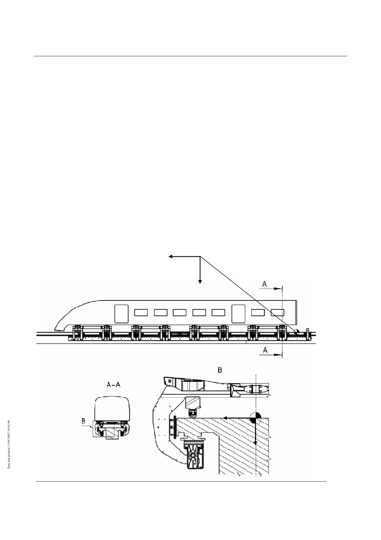
High-speed Maglev system
Maglev Technical Committee
Design principles
Vehicle
Definitions (subsystem-specific)
Coordinate system
• Coordinate system, see Figure 69:
x-direction:
in direction of end section 1 of the vehicle
y-direction:
at right angles to the running direction in the sliding surface
to the right
z-direction:
vertical to the running direction, positive axis oriented
downwards
• Origin of the coordinate system is the gradients of the guideway and, in the x-direction for
the vehicle, the guideway centre; see MSB AG-GESAMTSYS, figure 3 and figure. When
considering individual sections, the origin lies in the x-direction in the centre of the section
coupling.
z
z
WK
∆y8
WK
∆y8
Title
High-speed Maglev system design principles
Vehicle, Part III, Kinematic Gauge
Document
67650
Version
White Paper Issue date
15.02.2007
Page 9
no.:
High-speed Maglev system
Maglev Technical Committee
Design principles
Vehicle
Figure 69: Vehicle coordinate system
Title
High-speed Maglev system design principles
Vehicle, Part III, Kinematic Gauge
Document
67650
Version
White Paper Issue date
15.02.2007
Page 10
no.:
High-speed Maglev system
Maglev Technical Committee
Design principles
Vehicle
Concepts
• The definitions in MSB AG-ABK&DEF are applicable. The concepts explained in this chap-
ter are necessary for understanding of this document. They complement the concepts in
MSB AG-ABK&DEF.
Normal coordinates Orthogonal coordinates defined in a plane normal to the centreline of the
guideway in nominal position.
Horizontal axis (y-axis): intersection of the specified plane and the sliding
surface (running surface in the case of railway vehicles).
Vertical axis (z-axis): Perpendicular to horizontal axis, at equal distance
from the slide rails (rails in the case of railway vehicles).
Maximum construc-
Profile, in relation to the cross section to be investigated, which the various
tion gauge
parts of the vehicles must respect (vehicle profile)
Kinematic gauge
This is the theoretical centre of a vehicle in relation to the normal coordi-
nates, taking into account the most unfavourable positions of the levitation
chassis on the guideway and the quasi-static movements of the carriage
body. No account is taken of random factors (oscillations, asymmetries).
Rolling
Rotational motion of the carriage body or levitation chassis around the x-
axis
Pitching
Rotational motion of the carriage body or levitation chassis around the y-
axis
Yawing
Rotational motion of the carriage body or levitation chassis around the z-
axis
Title
High-speed Maglev system design principles
Vehicle, Part III, Kinematic Gauge
Document
67650
Version
White Paper Issue date
15.02.2007
Page 11
no.:
High-speed Maglev system
Maglev Technical Committee
Design principles
Vehicle
Abbreviations
•
The abbreviations pursuant to MSB AG-ABK&DEF are applicable. The abbreviations ex-
plained in this chapter are necessary for understanding of this document. They complement
the concepts in MSB AG-ABK&DEF.
•
GE
Sliding surface
GL
Slide rail
GLM
Sliding surface centre distance
ay
Free y-lateral acceleration (cornering)
az
z-acceleration (g + passing over concave / convex transition curves)
C
Centre of rotation of the carriage body rotation
c
Spring constants
cpiE
Stiffness of the z-settling springs i, in relation to the swing axle
cZF
Stiffness of the y-auxiliary springs
cηWK
Roll stiffness of carriage body, in relation to pendulum
d
Distance between guidance magnet gap sensors
FKz1
z-coupling force of section coupling of end section 1 to central section
FKz2
z-coupling force of section coupling of end section 2 to central section
FmWKy
y-inertia force of carriage body (cant deficiency)
FmWKz
z-inertia force of carriage body
Fpiy
y-pendular force of levitation frame i
Fpiz
z-pendular force of levitation frame i
Fp1z
z-pendular force of nose levitation frame end section
∆Fpz
Deviation of z-pendular force from nominal load
FpzLFi
z-pendular force pneumatic spring circuit i
FZFiy
y-force at y-auxiliary springs of levitation frame i
FySW
Crosswind force on end section E, central section M
FzWK
z-forces of carriage body end section E, central section M
FyWK
y-forces of carriage body end section E, central section M
∆fy
Force-dependent static y- deflection of the frame structure with excited guidance
magnet and deviation from the nominal load
∆fz
Force-dependent static deflection or rebound in the case of deviations from the nomi-
nal load
∆fzG
Force-dependent static deflection or rebound of the frame structure in the case of
deviations from the nominal load
∆fzTM
Force-dependent static deflection or rebound of the support magnet linkage in the
Title
High-speed Maglev system design principles
Vehicle, Part III, Kinematic Gauge
Document
67650
Version
White Paper Issue date
15.02.2007
Page 12
no.:
High-speed Maglev system
Maglev Technical Committee
Design principles
Vehicle
case of deviations from the nominal load
∆fzTK
Static deflection of the support skid in settled vehicle
F
Nominal gap guidance
FR
Guidance gap on cornering (nominal gap)
fz
z-displacements
LFM
Magnet length of guidance magnet
lp
Pendulum length
mWK
Carriage body mass
MT
Rolling moment carriage body
∆P
Wear on terminal strip of guidance magnet
P
Maximum terminal strip wear
R
Guideway radius of curvature (Rxz or Rxy)
Rxz
Radius convex / concave transition curve
Rxy
Radius of curve
S
Projection in cornering
s0
Nominal air gap of support / guidance magnet
∆s
Dynamic gap deviation in support / guidance air gap
∆s1
Gap difference in guidance magnet centre during cornering
∆s2
Gap difference at the guidance magnet end during cornering
T
Support skid gap
∆V
Wear on support skid coating
Wz
Nominal dimension of guideway gripper between top of the sliding surface and lower
surface of the stator pack
∆Wz
z-construction tolerances of guideway gripper dimension
Wy
Guideway track gauge (distance between lateral guide rails)
∆Wy
y-construction tolerances of guideway track gauge
xiE
Distance from the z-settling spring i to the section coupling
xNiE
Distance from the z-settling spring i to the pivot point of carriage body pitching
xsi
Distance from resulting point of application of force of pneumatic spring circuit i to
section coupling
xsE
x-distance from end section centre of gravity to section coupling
xSWE
Distance from end section crosswind to section coupling
xZFi
Distance from y-auxiliary spring i to section coupling
x2E
Distance from levitation frame of end section 2 to section coupling
yK
y-displacement of the section coupling
ysWK
y-centre of gravity coordinates of carriage body
ypiE
y-displacement of pendulum i of end section
Title
High-speed Maglev system design principles
Vehicle, Part III, Kinematic Gauge
Document
67650
Version
White Paper Issue date
15.02.2007
Page 13
no.:
High-speed Maglev system
Maglev Technical Committee
Design principles
Vehicle
∆yi
y-displacement of levitation frame i
Y
Vehicle track gauge
YA
Vehicle track gauge in failure situations or with mechanical guidance
Y0
Nominal vehicle track gauge with non-excited guidance magnets (settled vehicle)
∆y
y-construction tolerances of vehicle track gauge
yp
y-coordinates point of application of force of carriage body pendulum
zK
z-displacement of the section coupling
zsE
z-distance from end section centre of gravity to section coupling
zpiE
z-displacement of pendulum i end section
zsWK
z-centre of gravity coordinates of carriage body
zC
z-coordinates pivot point of carriage body rolling
∆zi
z-displacement of levitation frame i
Z
Gripper dimension between lower surface of support skid and top of support magnet
Z0
Nominal dimension of vehicle gripper between lower surface of support skid and top
of support magnet in relation to the nominal load on the support magnet (levitated
vehicle)
∆z
z-construction tolerances vehicle gripper dimension
α
Guideway - angle of lateral inclination
γ bzw. γxz
Pitch angle (rotation around y-axis)
γ0xz
Static pitch angle from asymmetry of loading
δ bzw. δxy Yaw angle (rotation around the z-axis)
δ0xy
Static yaw angle from asymmetry of loading
η bzw. ηyz Roll angle (rotation around x-axis)
η0yz
Static roll angle from asymmetry of loading
ηyzFy
Roll angle of carriage body from centrifugal force and crosswind
ηyzα’
Roll angle of carriage body from guideway canting
Title
High-speed Maglev system design principles
Vehicle, Part III, Kinematic Gauge
Document
67650
Version
White Paper Issue date
15.02.2007
Page 14
no.:
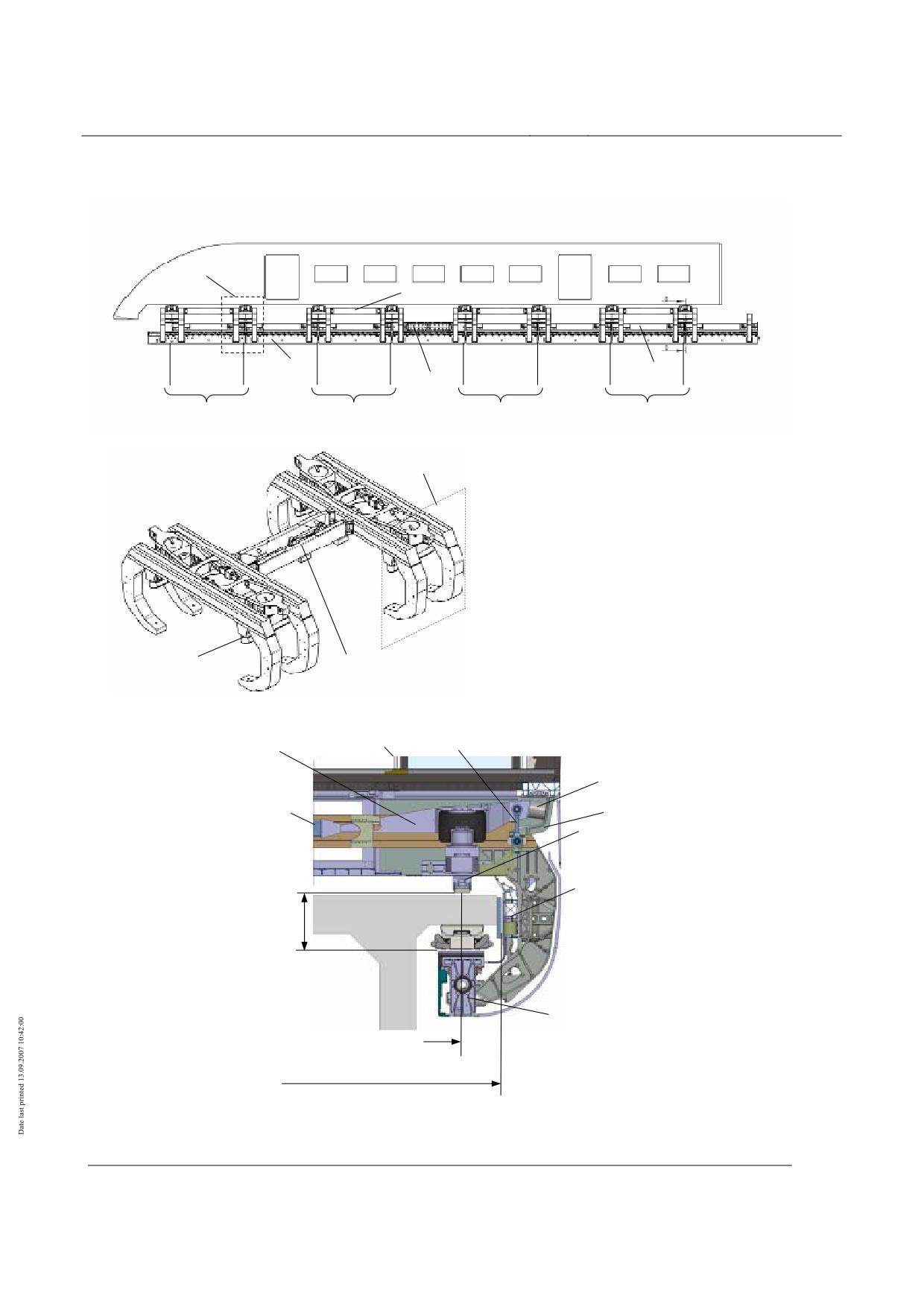
High-speed Maglev system
Maglev Technical Committee
Design principles
Vehicle
Definitions and terminology
WK
∆
WK
∆
WK
WK
WK
∆
WK
WK
WK
WK
WK
WK
WK∆
WK
∆
WK
WK
WK
WK
∆
∆
∆
∆
WK
WK
WK
∆yp8
∆yp8
∆yp1
δxy
C
∆zp8
(Le
vel
WK
WK
Pneumatic spring
WK
WK
WK
WK
WK
WK
WK
WK
WK
∆yp8
WK
WK
∆yp8
WK
Figure 70: Side view and cross-section of a vehicle (diagrammatic representation)
Title
High-speed Maglev system design principles
Vehicle, Part III, Kinematic Gauge
Document
67650
Version
White Paper Issue date
15.02.2007
Page 15
no.:
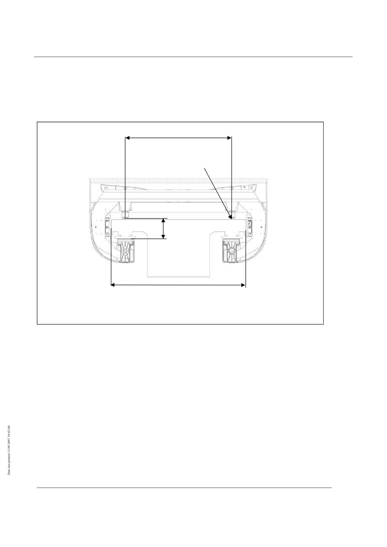
High-speed Maglev system
Maglev Technical Committee
Design principles
Vehicle
WK
WK
WK
WK
Figure 71: Relevant geometric definitions of guideway dimensions
Title
High-speed Maglev system design principles
Vehicle, Part III, Kinematic Gauge
Document
67650
Version
White Paper Issue date
15.02.2007
Page 16
no.:
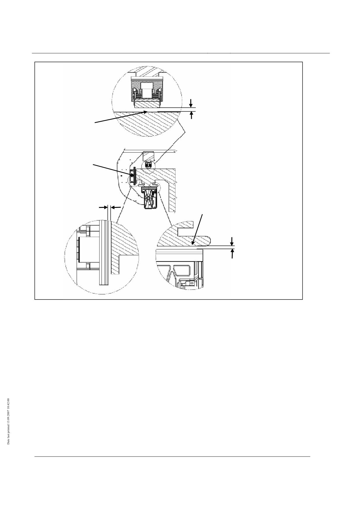
High-speed Maglev system
Maglev Technical Committee
Design principles
Vehicle
WK
WK
WK
WK
WK
WK
Figure 72: Characteristic quantities for the kinematics of maglev vehicles
Title
High-speed Maglev system design principles
Vehicle, Part III, Kinematic Gauge
Document
67650
Version
White Paper Issue date
15.02.2007
Page 17
no.:
High-speed Maglev system
Maglev Technical Committee
Design principles
Vehicle
Alignment parameters
• The following alignment parameters must be taken into account:
Concave transition curve:
Vertical radius Rxz
530 m
Convex transition curve:
Vertical radius Rxz
530 m
Curve:
Horizontal radius Rxy 1000 m
• Different values may be agreed on a project-specific basis. Smaller specified alignment pa-
rameters must be demonstrated by the manufacturer with regard to the aspect of non-
contact between guideway and vehicle.
• These investigations do not form part of the demonstration regarding the kinematic gauge.
Loading gauge
• The loading gauge shown in Figure 73 corresponds to the loading gauge line C (MbBO) for
straight tracks. Figure 74 shows the loading gauge for curve radii < 3500 m. Dimensions of
the guideway boundary not shown in the MbBO have been added without an indication of
tolerances.
Title
High-speed Maglev system design principles
Vehicle, Part III, Kinematic Gauge
Document
67650
Version
White Paper Issue date
15.02.2007
Page 18
no.:
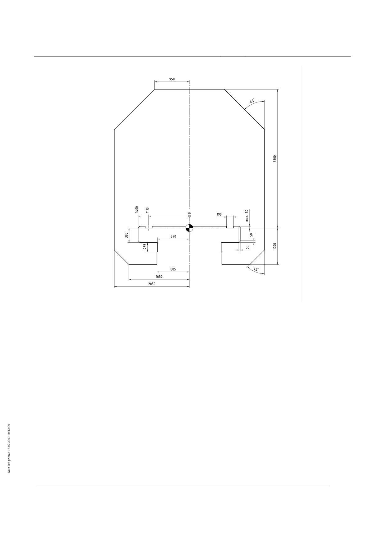
High-speed Maglev system
Maglev Technical Committee
Design principles
Vehicle
Figure 73: Gauge of maglev vehicles - straight track
Title
High-speed Maglev system design principles
Vehicle, Part III, Kinematic Gauge
Document
67650
Version
White Paper Issue date
15.02.2007
Page 19
no.:
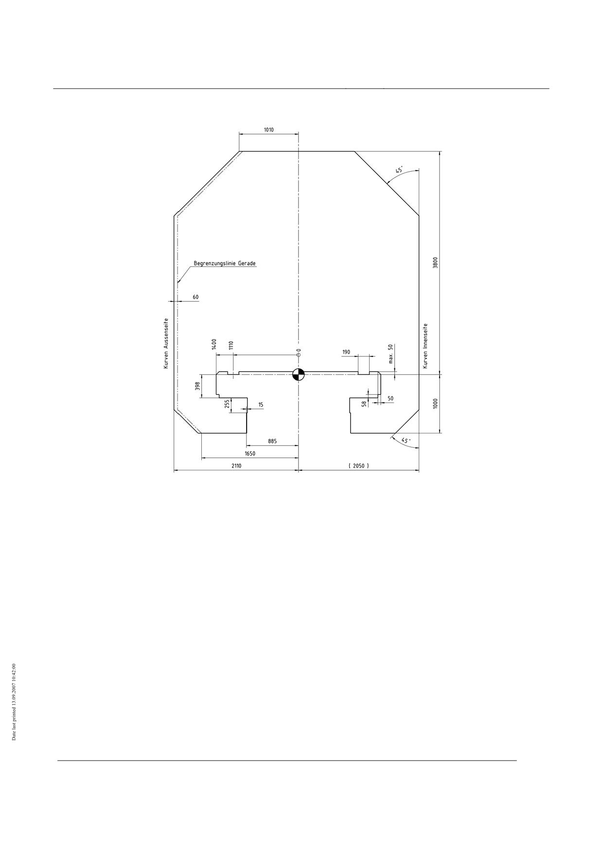
High-speed Maglev system
Maglev Technical Committee
Design principles
Vehicle
Figure 74: Loading gauge of maglev vehicles - curve radius 350 m to 3500 m
Key
Begrenzungslinie Gerade = Loading gauge straight track
Kurven Aussenseite = Outside of curves
Kurven Innenseite = Inside of curves
Title
High-speed Maglev system design principles
Vehicle, Part III, Kinematic Gauge
Document
67650
Version
White Paper Issue date
15.02.2007
Page 20
no.:
High-speed Maglev system
Maglev Technical Committee
Design principles
Vehicle
Demonstration procedure
• The following procedure should be used to demonstrate the kinematic gauge of the maglev
vehicle. Differences must be agreed on a project-specific basis.
• The displacements and torsions of the carriage body and the displacements of the levitation
chassis must be applied to the guideway.
• The superimposing of the carriage body displacements with the displacements of the levita-
tion chassis produces the overall displacements of the carriage body.
• The overall displacement of the carriage body must be determined by superimposing the
carriage body displacement with the displacements of the levitation chassis.
• The resulting displacements of the vehicle external profile must be checked against the
loading gauge in the MbBO.
• The carriage body must then be regarded as a rigid body. The elastic forces of the levita-
tion chassis to be taken into account must then be included in the corresponding displace-
ments of the levitation chassis.
• The displacements / deformations of the carriage body and the levitation chassis must be
determined separately and then superimposed.
• The displacements are deduced for the carriage body in Chapter 0, and for the levitation
chassis in Chapter 0.
• Analytical procedures or suitable software applications (e.g. CAD software products) may
be used for this definitive examination of the boundary envelope.
• The following conditions must form the basis for the demonstration procedure, where appli-
cable:
Centres of rotation are assumed in order to deduce the displacements from rolling / pitching / yaw-
ing. The resulting centre of rotation shifts as a result of superimposing of the displacements.
The position of the resulting centre of rotation precludes certain superimpositions because of
the constraining kinematic conditions.
The position of the resulting centre of rotation must be tested. The individual movements must
be corrected subsequently when the individual displacements are superimposed.
Construction tolerances of the carriage body must be taken into account. The construction toler-
ances of the levitation chassis should be disregarded as support and guidance gaps are ad-
justed to the specified dimension.
The specified wear caused by vehicles on the support skid coatings and the terminal strips of the
guidance magnets must be taken into account.
Wear and construction tolerances in respect of the guideway are disregarded. These are recorded
above range B, MbBO, fig. 1.
Deflections and elastic deformations (bending, torsion) for the carriage body must not be taken into
account.
The elastic deformations from support (z-loads) and guidance (y-loads) must be taken into ac-
count for the levitation chassis.
Pneumatic suspension:
A distinction must be made between the cases of pressurised and/or deflated cushions. With
Title
High-speed Maglev system design principles
Vehicle, Part III, Kinematic Gauge
Document
67650
Version
White Paper Issue date
15.02.2007
Page 21
no.:
High-speed Maglev system
Maglev Technical Committee
Design principles
Vehicle
depressurised pneumatic springs, allowance must be made for the spring suspension via the
settling springs.
Rubber and steel springs
Deflection under static load must be taken into account, if necessary allowance for additional
deflection from dynamic stresses. Deflections because of suspension tolerances may be disre-
garded. These are included in the adjustment tolerances of the magnet linkages.
The support/guidance function of the maglev vehicle is designed as an active system; in the case
of failure, the function of the individual systems is taken over by adjacent systems on the basis
of the redundant design. Corresponding proof is provided inter alia by means of FMEA analy-
ses during the development of the Transrapid vehicles. Adequate support behaviour is also
validated by means of the demonstration.
Component failure of structural assemblies of the support / guidance system (components in
the primary power flux, e.g. support bracket) may not lead to the loading gauges pursuant to
Chapter 0 being breached.
In the case of a specified failure of the magnetic support or guidance function, the loads are dis-
persed mechanically via the support skids and/or guidance magnets. This state must be taken
into account when deducing the support or guidance gap.
Crosswind action must be taken into account. The aerodynamic lift on the carriage body may be
disregarded. Local aerodynamic loads from trains passing and tunnel operation may also be
disregarded.6
The different loading states must be taken into account (vehicle deadweight, mean and permissible
vehicle weight as well as maximum vehicle weight, see also MSB AG-FZ BEM).
Maximum carriage body load: assessment of the larger value of
a. 30 % excess load in relation to the maximum payload at maximum capacity utilisation,
b. Load in the case of evacuation (maximum vehicle weight), if relevant for the application.
An additional clearance requirement for attachments to the carriage body (e.g. radio aerials, Figure
80) must be taken into account on a project-specific basis.
6 Local effects are not taken into account because the carriage body is regarded as a rigid body.
The required vehicle rigidity is dealt with in MSB AG-FZ BEM.
Title
High-speed Maglev system design principles
Vehicle, Part III, Kinematic Gauge
Document
67650
Version
White Paper Issue date
15.02.2007
Page 22
no.:
High-speed Maglev system
Maglev Technical Committee
Design principles
Vehicle
Kinematic degrees of freedom of carriage body
• The carriage body has the following rigid-body degrees of freedom:
z-displacement of carriage body (deflection, rebound),
y-displacements (lateral movements),
rolling around the longitudinal axis (roll in the case of rail vehicles),
pitching around the transverse axis (non-uniform z-displacement),
yawing around the vertical axis (non-uniform y-displacement).
• Below, the z-displacements are considered with pitching of the carriage body, and the y-
displacements together with yawing of the carriage body.
• To obtain the absolute carriage body displacements, the displacements of the levitation
chassis must be superimposed with the displacements deduced below.
• The statements in the sections of Chapter 0 must be taken into account.
Rolling of carriage body
•
The quasi-static rolling of the carriage body is considered on the basis of the characteristics
of the secondary suspension. Stops which limit the movement of the carriage body to the
levitation chassis are taken into account. Characteristic quantity is the roll angle ηyz.
Concepts regarding carriage body rolling
Pivot point of carriage body rolling
• The centre of rotation of carriage body rolling C (roll centre C in rail vehicles) is not fixed
because of the pendulum characteristics. For straight rolling it is situated in the vehicle cen-
tre in the section coupling (Figure 75). The centre of rotation C moves upwards as a result
of the lateral displacement caused by the gravity pendulum.
• As the roll angle would be reduced as a result of the upward displacement of the centre of
rotation, the centre of rotation C is situated in the section coupling for the purposes of dem-
onstration and is assumed to be fixed.
•
Asymmetry η0yz
• Asymmetry η0yz is the static roll angle of the carriage body as a result of offset of the load
with a level guideway. The offset is recorded by means of the position of the carriage body
centre of gravity xSE.
•
Guideway canting
• Guideway canting (lateral inclination α) means the difference in elevation of the inner curve
of the stator surfaces compared to the outer curve.
Title
High-speed Maglev system design principles
Vehicle, Part III, Kinematic Gauge
Document
67650
Version
White Paper Issue date
15.02.2007
Page 23
no.:
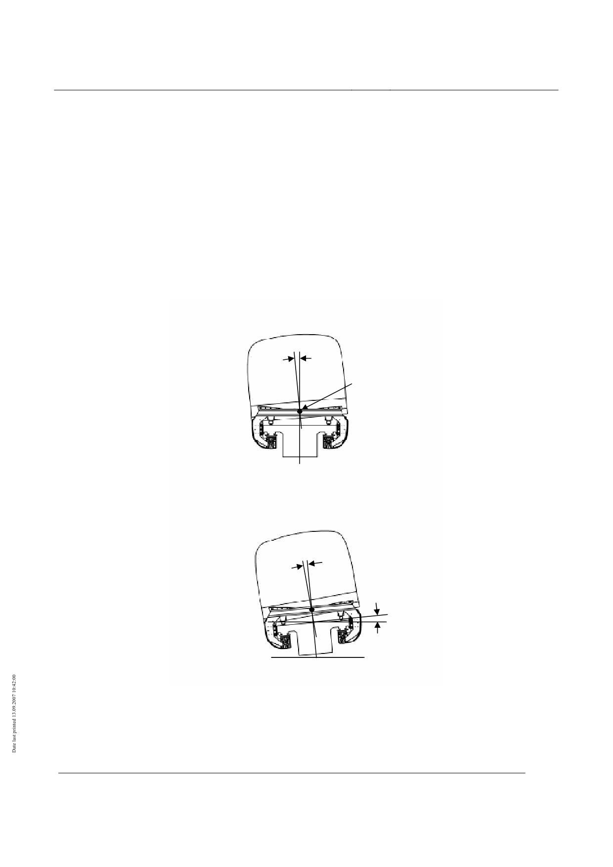
High-speed Maglev system
Maglev Technical Committee
Design principles
Vehicle
Rolling caused by cant deficiency
• The cant deficiency is the dimension by which the actual guideway cant differs from the
compensatory cant. The maximum lateral acceleration ay is set for the investigations.
•
Rolling caused by gravity
• When the vehicle is standing on a canted guideway, the sliding surface of which forms an
angle α with the horizontal line, the carriage body rotates and forms an angle ηyz with the
perpendicular to the guideway.
• The roll angle is dependent on the load state of the vehicle. The greatest load value in the
most unfavourable load state is taken into account.
WK
WK
WK
WK
∆y8
Figure 75: Vehicle kinematics - Rolling of carriage body
Title
High-speed Maglev system design principles
Vehicle, Part III, Kinematic Gauge
Document
67650
Version
White Paper Issue date
15.02.2007
Page 24
no.:
High-speed Maglev system
Maglev Technical Committee
Design principles
Vehicle
Rolling load cases to be examined
• The roll angle can be calculated in accordance with Chapter 0. The calculation method
applies to maglev vehicles in accordance with MSB AG-FZ GEN.
• The settling springs are disregarded when determining the roll stiffness. Depressurised
pneumatic springs, i.e. where the carriage body is supported on the 16 settling springs, re-
sult in a higher roll stiffness and thus a reduced roll angle. The structure leaves the loading
gauge as a result of the simultaneous lowering of the level. Thus, an intact pneumatic sus-
pension (if present) is taken into consideration for rolling.
• The following cases must be tested:
Vehicle stands on maximum canted guideway - rolling caused by gravity
Vehicle runs on guideway with cant deficiency - rolling caused by centrifugal force
The effect of crosswind and asymmetry η0yz must be taken into account for both cases.
• The input parameters for deducing the roll angle of the carriage body are given in Chapter
0. Depending on the superimposition of load cases, the data to be taken into account such
as guideway alignment, lateral accelerations to be assessed, carriage body dimensions,
asymmetries of the load and crosswind speeds are given in the chapter.
Title
High-speed Maglev system design principles
Vehicle, Part III, Kinematic Gauge
Document
67650
Version
White Paper Issue date
15.02.2007
Page 25
no.:
High-speed Maglev system
Maglev Technical Committee
Design principles
Vehicle
Z-displacements / pitching of carriage body
• The quasi-static deflection/rebound and pitching of the carriage body is considered on the
basis of the secondary suspension characteristics.
•
Stops which limit the movement of the carriage body to the levitation chassis are taken into
account. Characteristic quantity: displacement z and pitch angle γxz.
Concepts regarding carriage body z-displacements / pitching
Pivot point of carriage body pitching
• With active pneumatic suspension the pivot point is situated in the section coupling (Figure
76).
• With full venting of a pneumatic spring circuit, the pivot point ideally lies in the level re-
cording point of the adjacent active pneumatic spring circuit of the section. The level re-
cording points are vehicle-specific and, pursuant to MSB AG-FZ GEN, are located in the
first and last levitation frame for maglev vehicles (Figure 76).
•
Vehicle height
The vehicle heights for the empty (unloaded) and full (loaded) vehicle considered.
Downward vertical displacements f1
• The vertical displacement f1 7 is made up of the deflection ∆fz and the supplementary dis-
placements fz (see 0). In a levitated vehicle, the deflection ∆fz is made up of the spring
travel of the secondary suspension, the spring travel of the support magnet linkage and the
elastic force of the levitation chassis. In a settled vehicle, the deflection ∆ fz consists of the
spring travel of the secondary suspension and the deflection of the support skid. The values
for spring travel of the secondary suspension correspond to the derived carriage body dis-
placements.
• The deflection of the levitation chassis is considered separately in 0.
• The vertical deflection is taken into account at max. operating loading.
Upward vertical displacement f2
• The vertical displacement f2 7 is obtained from the rebound ∆fz of the secondary suspension
and the levitation chassis.
• In a levitated vehicle, the rebound ∆fz is made up of the spring travel of the secondary sus-
pension, the spring travel of the support magnet linkage and the elastic force of the levita-
tion chassis.
• In a settled vehicle, the rebound ∆fz corresponds to the spring travel of the secondary sus-
pension, i.e. the derived carriage body displacements.
7 For terminology, see DIN 27505
Title
High-speed Maglev system design principles
Vehicle, Part III, Kinematic Gauge
Document
67650
Version
White Paper Issue date
15.02.2007
Page 26
no.: