Design Principles High-speed Maglev System. Information (MSB, 2007) - page 11
High-speed maglev systems
Maglev Technical Committee
Design principles
Guideway
py,axWSV,i,ZG (l)
-
8.5
0.5
0
6.2
0.5
0
-
-
4.6
0
0
4.8
1.1
0
0
Middle sections
FMTi in
[kN/m]
1
2
3
4
5
6
7
BM
10
11
12
13
14
15
16
py,axWSV,i,ZG (r)
0
0
1.7
4.3
0
0
4.7
-
-
0
1.1
5.8
0
0
1.4
4.4
py,axWSV,i,ZG (l)
5
0.8
0
0
6.2
0.6
0
-
-
4.8
0
0
4.9
1.1
0
0
The actions listed in this table take into account the permissible vehicle weight according to Table 100 and the max.
permissible braking/propulsion acceleration according to Table 91.
The force balance of the end sections is not balanced (transfer of a remaining force over the section coupling).
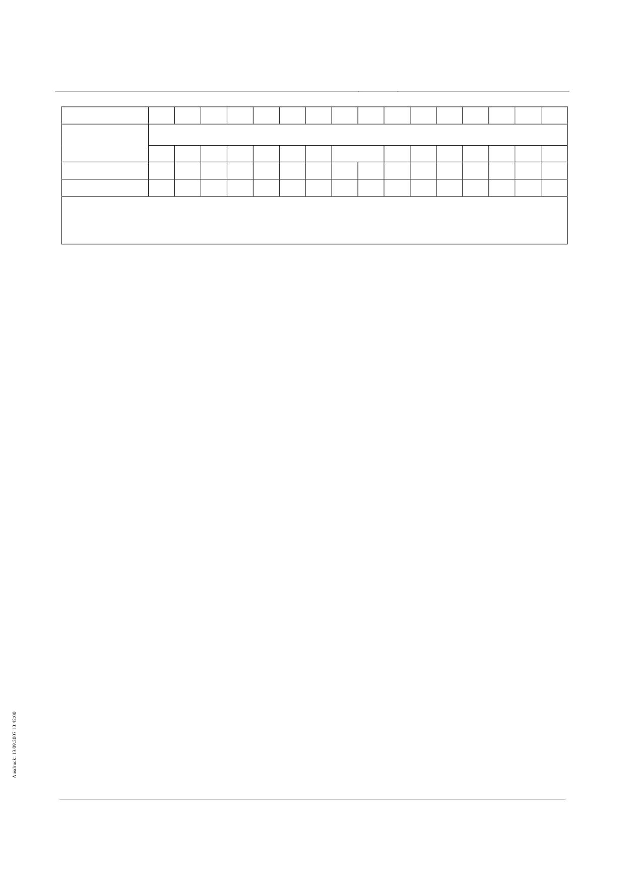
Table 104 - Typical distribution of the guidance magnets from ax,WSV
Title
High-speed Maglev Systems - Design principles
Guideway - Part II: Design
Doc. no.:
57288
Version
White Paper Issue date
15.02.2007
Page 59

High-speed maglev systems
Maglev Technical Committee
Design principles
Guideway
Actions in z-direction (Q1.. Q3)
Acceleration in z-direction
(4)
The actions from the vehicle weight as a consequence of az (see equation (4)) in z-direction
are to be established with the help of the subsequent equations (14) and (15) and the distri-
bution given in table 105 over the vehicle length (see chapter 0).
a
z
( 14)
p
=
p
⋅
in [kN/m]
z,a
z
,EG/MG/ZG/HG
Z,EG/MG/ZG/HG
g
(5)
The limit values for az are to be taken from Table 91.
(6)
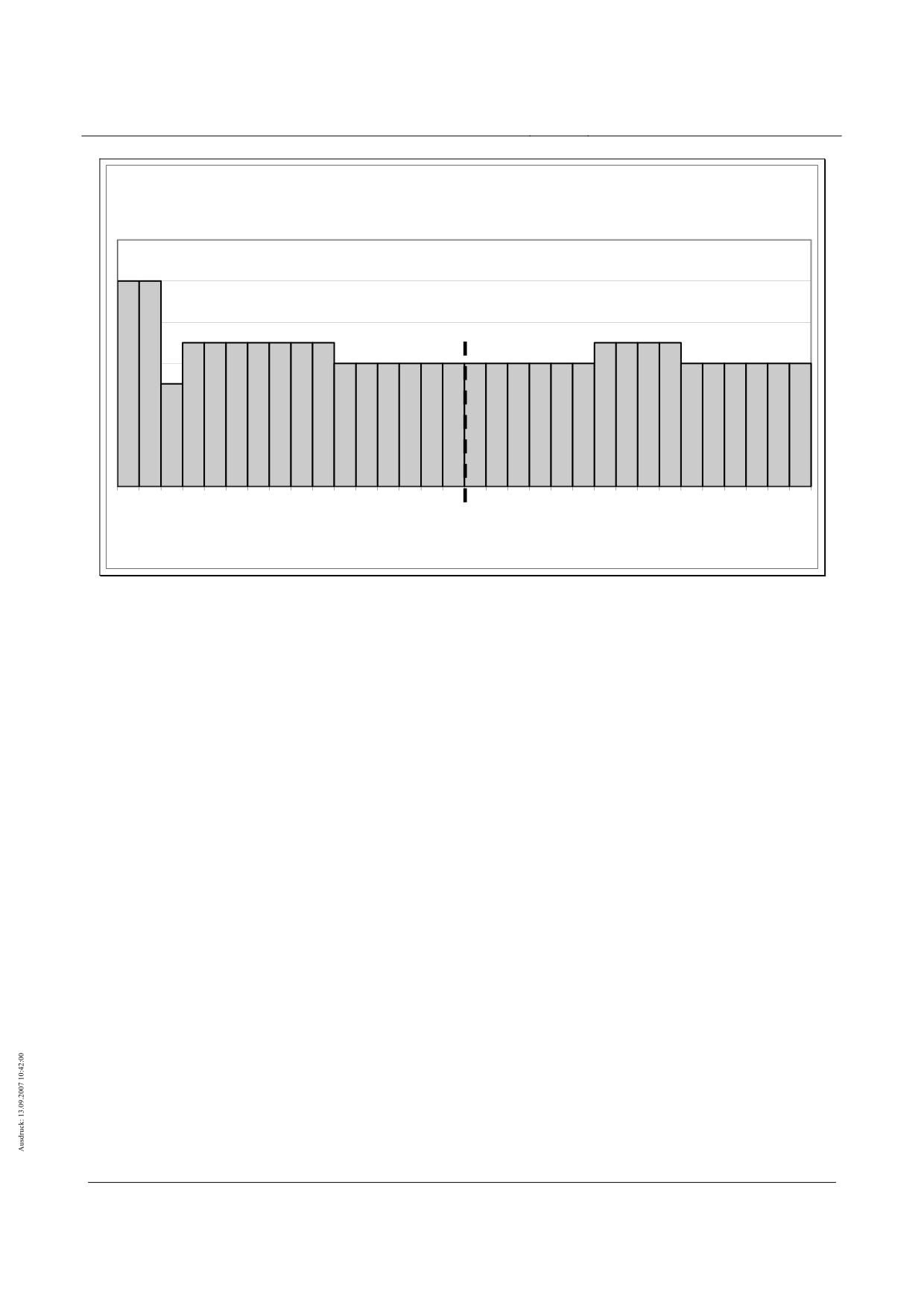
For the individual partial magnets TMTi according to figure 121 the corresponding forces are
to be determined according to equation ( 15). In the distribution of the partial magnet actions
the unequal distribution through the factors kz,az,i (see table 105) as a consequence of vehi-
cle centre of gravity position in x-direction is included following chapter 0.
L
a
k
ES/MS
z
z,az,i
p
=
0,5
⋅
p
⋅
⋅
⋅
in [kN/m]
( 15)
z,az,TMT
i
,EG/MG/ZG/HG
Z,EG/MG /ZG/HG
L
g
100
TMT
i
(7)
Component dynamics and control dynamics following chapter 0 are to be taken into account.
End sections
TMT
i
1 *
2
3
4
5
6
7
8
9
10
11
12
13
14
15
16
kz,az,i
10
10
5
7
7
7
7
7
7
7
6
6
6
6
6
6
[%]
Middle sections
TMT
i
1
2
3
4
5
6
7
8
9
10
11
12
13
14
15
16
kz,az,i
6
6
6
6
6
6
7
7
7
7
6
6
6
6
6
6
[%]
* TMT1 conforms as typical extension of TMT2 (see figure 122).
Table 105 - Typical distribution of the guidance magnet forces from az over the length of the vehicle
Title
High-speed Maglev Systems - Design principles
Guideway - Part II: Design
Doc. no.:
57288
Version
White Paper Issue date
15.02.2007
Page 60
High-speed maglev systems
Maglev Technical Committee
Design principles
Guideway
Acceleration and braking
(1)
The pitching moments of the carriage body round the y-axis as a consequence of the centre of gravity
distance in z-direction (see chapter 0) while braking and accelerating are to be taken into account in
accordance with the load arrangement (loading and unloading) in accordance with figure 131 (circuits
of air suspension connection) (here see also the force distribution from the tilting of the support-
guidance structure following chapter 0).
(2)
This load arrangement is to the unfavourably transferred to the static guideway load following chapter
0.
(3)
Component dynamics and control dynamics following chapter 0 are to be taken into account.
Endsektionen
Mittelsektionen
0 bzw. -(+) ∆pz,ax
0 bzw. -(+) ∆pz,ax
0 bzw. +(-) ∆pz,ax
0 bzw. +(-) ∆pz,ax
x
y
14,465 m
9,288 m
12,384 m
12,384 m
z
Mit max ∆pz,ax = +(-) 0,5 kN/m bei ax = 1,5 m/s²
(+ ∆pz,ax bei Bremsung, - ∆pz,ax bei Beschleunigung)
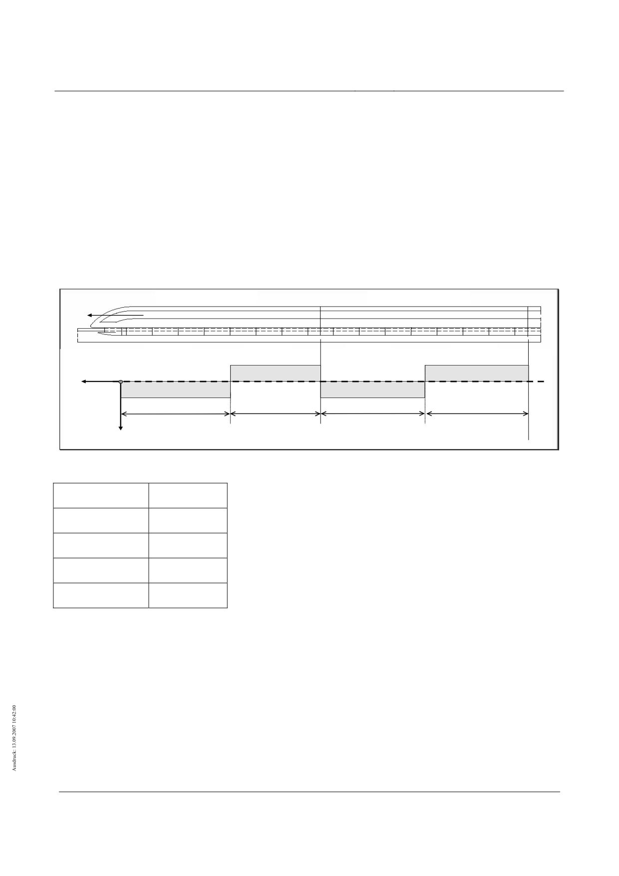
Figure 131- Typical additional loads in z-direction as a consequence of braking/accelerating
Endsektionen
End sections
Mittelsektionen
Middle sections
Mit max
With max
Bei Bremsung
For braking
Bei Beschleunigung
For acceleration
Title
High-speed Maglev Systems - Design principles
Guideway - Part II: Design
Doc. no.:
57288
Version
White Paper Issue date
15.02.2007
Page 61
High-speed maglev systems
Maglev Technical Committee
Design principles
Guideway
Special operating situations
Regulated setting down of the vehicle at v = 0 km/h (Q1, Q2)
(45) With regulated setting down in stations and operating structures dynamic actions are created on the
guideway via the support skids. The static action from a support skid is to be established in the follow-
ing way:
F
= (p
+p
)⋅L
;
in [kN]
z,TK,j/j+1
z,az,TMT
j
z,az,TMT
j+1
sys,TMT
( 16)
with pz,az,TMT from equation ( 15) and j = 1, 3, 5, 7, 9, 11, 13, 15
(46) Component dynamics and control dynamics following chapter 0 are to be taken into account.
(47) The time function of the regulated setting down to be taken into account is to be taken from figure 135
in chapter (8)
(48) The forces which occur as a consequence of guideway longitudinal and crossways tilting as a conse-
quence of the friction coefficient µ (see table 98) for a support skid Fx/y,TK in x- and/or y-direction which
are limited by the maximum forces max Fx/y,TK dependent on the friction coefficient are to be applied
following equation (17) and (18).
y
a
( 17)
F
=
F
⋅
whereby
max F
= µ⋅F
;
in [kN]
y,TK
z,TK
y,TK
z,TK
a
z
and
a
x
( 18)
F
x,TK
=
F
z,TK
⋅
whereby
max F
x,TK
= µ⋅F
z,TK
;
in [kN]
a
z
Set down vehicle (Q1, Q2)
(49) The actions from the operating condition “set down vehicle” are covered by the actions from the regu-
lated setting down process (see chapter 0).
Levitating vehicle and hovering (Q1, Q2)
(1)
The magnetic forces analogous to the previous chapter are to be applied.
(2)
Component dynamics and control dynamics following chapter 0 are to be taken into account. In this a
possible excitation of natural frequencies of the guideway is to be observed through the magnet regu-
lation above all (see chapter 0).
Title
High-speed Maglev Systems - Design principles
Guideway - Part II: Design
Doc. no.:
57288
Version
White Paper Issue date
15.02.2007
Page 62
High-speed maglev systems
Maglev Technical Committee
Design principles
Guideway
Aerodynamic actions from the vehicle (Q7, Q8)
Meeting of trains (Q7a)
(50) Additional guidance magnet forces as a consequence of a meeting of trains may be ignored on adher-
ence to the track centre distances stipulated.
Tunnel travel (Q7b)
(51) Direct actions from the vehicle
A reduced space (tunnel cross section) for the displacement of the air results through the tunnel. The
values indicated in table 107 for pressure and suction are to be applied with a 10% increase.
(52) Indirect actions as a consequence of the variability of the all-round pressure of the surrounding area
A change in pressure from 5500 Pa only effects the pressure tight closed cavities (e.g. cavity boxes of
guideway beams which are sealed through welding). This action is not to be transferred with the in-
creased pressure/suction value. It is recommended, in guideway areas in which corresponding
changes in pressure are possible not to use pressure tight guideway designs.
(53) Indirect actions as a consequence of reflected blast/suction waves
Actions as a consequence of reflected blast/suction waves are negligible.
(54) Unequal pressure distribution / air buffeting
The characteristic values of possible actions as a consequence of unequal pressure distribution and
air buffeting are to be set down project specifically with the available boundary conditions (tunnel cross
section, tunnel length, travel speed) being taken into consideration.
Actions on structures close to track/tunnels (Q7c)
(55) The actions on structures close to the track are to be taken from EN 1991-2 chapter 6.6 with the vehi-
cle width being taken into account. Here the width of the track vehicle is to be applied with 3.07m and
the width of the maglev vehicle with 3.70 m.
(56) The values for higher speeds are to be extrapolated in proportion to the squares of the speed.
(57) The factor k1 from EN 1991-2 chapter 6.6 for consideration of a favourable aerodynamic form is to be
applied with k1 = 0.6 (streamlined vehicle)
(58) Further coefficients are to be taken into account in line with EN 1991-2 chapter 6.6.
(59) Dynamic step ups through excitation of natural forms are to be proven.
Title
High-speed Maglev Systems - Design principles
Guideway - Part II: Design
Doc. no.:
57288
Version
White Paper Issue date
15.02.2007
Page 63
High-speed maglev systems
Maglev Technical Committee
Design principles
Guideway
Impulse (Q8a)
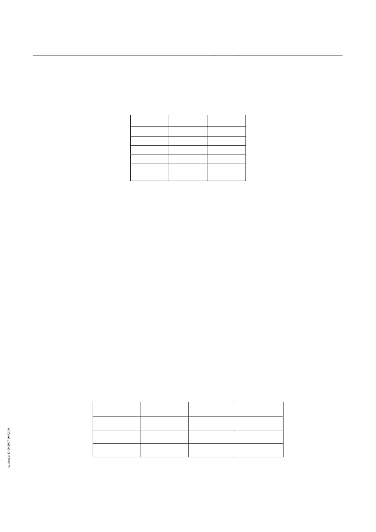
(60) The forces in table 106 in z- direction analogous to figure 133 are to be applied for the nose/tail sec-
tions as a function of the travel speed v.
v
pz,A,1
pz,A,2
[km/h]
[kN/m]
[kN/m]
0
0
0
200
-0.8
0.5
300
-1.8
1.2
400
-3.2
2.1
500
-5.0
3.2
Table 106 - Typical impulse forces nose/tail section
(61) For the middle sections the following impulse forces are to be applied continuously:
p
(v)
z,A,1
( 19)
p
(v)
=
in [kN/m]
z,A,3
3
(62) The impulse forces are only to be applied when they operate unfavourably.
(63) The impulse forces reduce the vertical loads. In verification of the positional stability the minimum vi-
bration coefficient (e.g.1/ϕz,Bg) is to be taken into account.
(64) The actions Q8a and Q9b are not to be applied simultaneously.
(65) Q8a is to be taken into account as an action effective against fatigue.
Direct pressure/suction action on the guideway (Q8b)
(66) Pressure and suction forces act on the guideway in the immediate vicinity of the vehicle. These are
dependent on the travelling speed and the respective location of the guideway cross section.
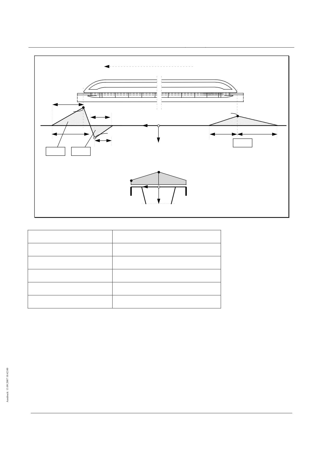
(67) On the upper side of the guideway a pressure/suction load in line with the distribution shown in figure
1323 is to be applied. The associated action quantities for v = 500 km/h (530 km/h) are to be taken
from table 107.
(68) The values for other travelling speeds are to be established quadratically with the speed interpolated.
v
qD/S,OG,1
qD/S,OG,2
qD/S,OG,3
0 km/h
0 kN/m²
0 kN/m²
0 kN/m²
500 km/h
+ 14 kN/m²
- 7 kN/m²
+ 7 kN/m²
530 km/h
+ 16 kN/m²
- 8 kN/m²
+ 8 kN/m²
Table 107 - Typical pressure - (+) and suction forces (-) on the upper side of the guideway
Title
High-speed Maglev Systems - Design principles
Guideway - Part II: Design
Doc. no.:
57288
Version
White Paper Issue date
15.02.2007
Page 64
High-speed maglev systems
Maglev Technical Committee
Design principles
Guideway
Fahrtrichtung
Endsektionen
2,5 m
qD/S,OG,1
1,0 m**
q
D/S,OG,3
x
y
3 m*
2 m
3 m
q
D/S,OG,2
z
Druck
0,7 m
Druck
Sog
Verteilung in Fahrweglängsrichtung
qD/S,OG,i
1/3 qD/S,OG,i
* Druck
22 ms bei v=500 km/h
y
x
** Sog
7 ms
"
z
Verteilung in Fahrwegquerrichtung
Figure 132 - Typical distribution of the pressure/suction action on the upper side of the guideway
Fahrtrichtung
Direction of travel
Endsektionen
End sections
Verteilung in Fahrweglängsrichtung
Distribution in guideway longitudinal direction
Druck
Pressure
Sog
Suction
Verteilung in Fahrwegquerrichtung
Distribution in guideway transverse direction
(69) If required the pressure/suction actions for other points on the guideway beam are to be specially es-
tablished whereby the diagram shown in figure 6 from /DIN Fachbericht 101/ for pressure load when a
vehicle travels by is to be used.
(70) Component dynamics are to be taken into account following chapter 0.
Wind on the vehicle (Q9)
General
(71) Subsequently the actions to be taken into account as a consequence of wind on stationary and mov-
ing vehicles are given (basis is /MSB AG-UMWELT/).
Title
High-speed Maglev Systems - Design principles
Guideway - Part II: Design
Doc. no.:
57288
Version
White Paper Issue date
15.02.2007
Page 65
High-speed maglev systems
Maglev Technical Committee
Design principles
Guideway
(72) Wind can bring about lateral forces and y-direction and moments via the weak point of the resulting
wind power round the x- and z- axis and impulse forces in z-direction.
(73) The sizes and the weak points of the actions as a consequence of wind on the vehicle are dependent
on the:
• Travel speed vFzg
• Wind speed vW,b or vW,m
• Geometry of the vehicle (c-value)
(74) The travel speed and the wind speed which occurs are dependent on the project and the location.
Action as a consequence of side wind on the vehicle (Q9a)
(75) As a basis for the wind speeds to be taken into account in the layout of the guideway the following
rounded nominal gust wind speeds (5 sec.-mean value) vb,10 at hW,Gelände = 10 m, which occur once per
year are to be assumed.
• Wind zone I
vW,b,10 = 27 m/s
• Wind zone II 19
vW,b,10 = 30 m/s
• Wind zone III
vW,b,10 = 34 m/s
• Wind zone IV
vW,b,10 = 38 m/s
(76) Opposite the ground speed vW,m,10 (10 min-mean value in 10m height and in 10 years) with a wind
speedvW,m,10 = 25 m/s for the wind zone II, there results a gust factor of 1.44 (e.g. wind zone II: (30
m/s)² / (25 m/s)² = 1.44). This factor covers a possible dynamic step up of the guideway requirement
from the wind on the vehicle at constant wind (10 min mean value; ground speed).
(77) Nominal gust wind speeds with different heights hW (in m) over land surface are to be calculated with
the help of equation (20) and zW= approx 1.3m and rounded up to whole numbers.
0,11
v
W,b,h
⎛
h
⎞
W
W
( 20)
=
with hW = hG, Gelände + zW in [m/s]
⎜
⎟
v
W,b,10
⎝
10 m
⎠
(78) As a consequence of the distance of the resultant force of the wind force in z-direction a track moment
is effective round the axis. The pair of forces which results from this in z-direction is introduced to the
guideway via the support magnets and is to be taken into account.
19 Decisive wind zone of the guideway regulation dimensioning for German applications.
Title
High-speed Maglev Systems - Design principles
Guideway - Part II: Design
Doc. no.:
57288
Version
White Paper Issue date
15.02.2007
Page 66
High-speed maglev systems
Maglev Technical Committee
Design principles
Guideway
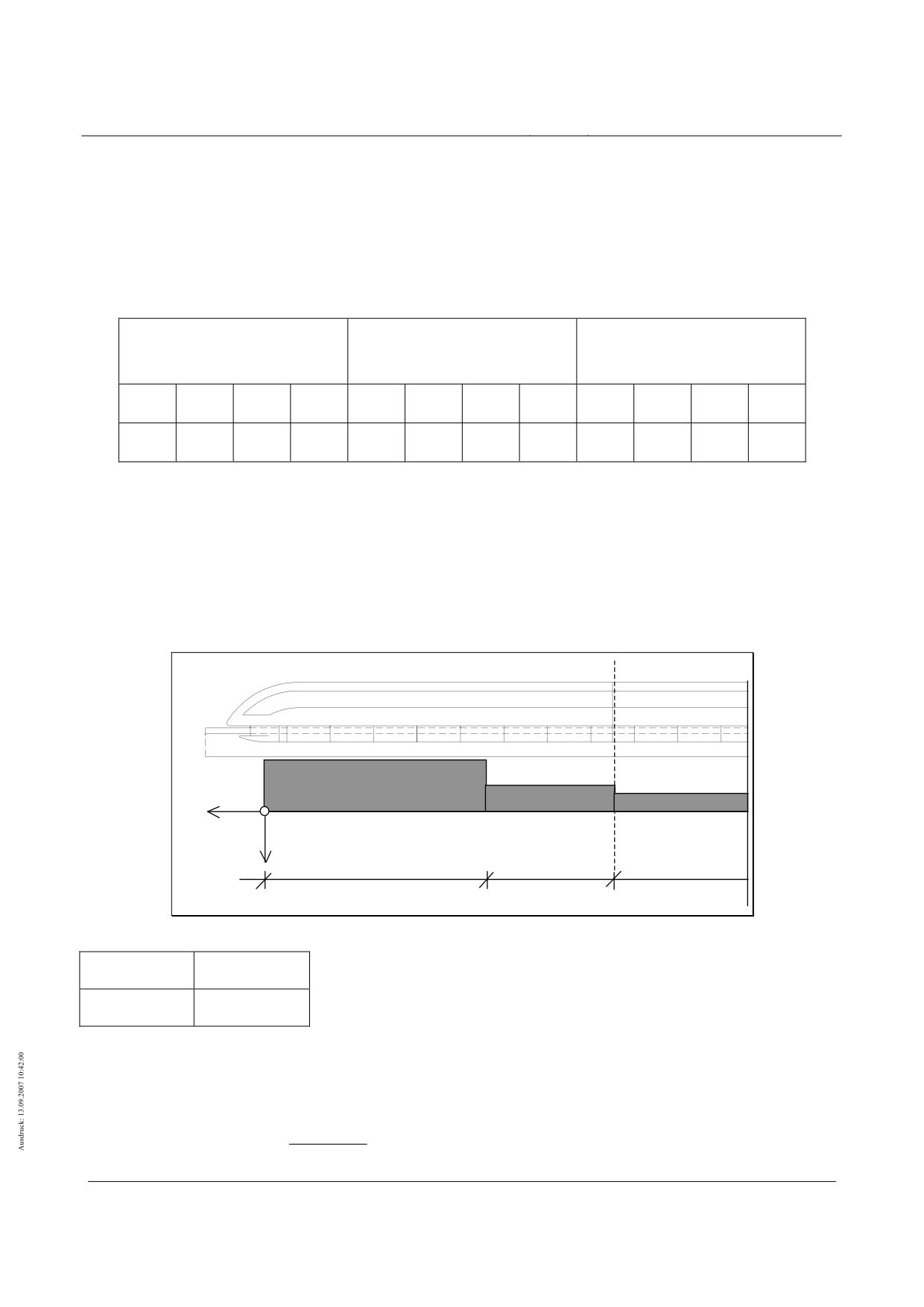
(79) The guidance and support magnet forces to be applied are to be taken from the tables contained in
Annex II-E (Tables 118 to 136) for various travel speeds and wind speeds (see e.g. table 108). The
forces for deviating travel speeds are to be established through linear interpolation for vFzg < 500 km/h
For travel speeds vFzg> 500 km/h the forces are to be established through extrapolation in proportion
to the squares of the travel speeds.
wind speed at
wind speed at
Wind speeds at hG,Gelände ≤ 4.0 m
4,0 m < hG,Gelände ≤ 13.0 m
13,0 m < hG,Gelände ≤ 20.0 m
in wind zone
in wind zone
in wind zone
I
II
III
IV
I
II
III
IV
I
II
III
IV
25
28
32
36
28
31
36
40
29
33
37
42
Table 108 - Wind speeds [m/s] with relevant guideway heights
Aerodynamic impulse as a consequence of wind (Q9b)
(80) The impulse forces for side wind are dependent on the travel speed and the wind speed and are to be
applied in line with table 109.
(81) The associated geometry is to be assumed in accordance with figure 24.
Endsektionen
Mittelsektionen
y
x
pz,AW,1
pz,AW,2
pz,AW,3
z
14,465 m
9,288 m
n x 24,768 m
Figure 133 - Typical load arrangement for the aerodynamic propulsion
Endsektionen
End sections
Mittelsektionen
Middle sections
(82) The impulse forces reduce the vertical loads and are only to be applied when they operate unfavoura-
bly.
(83) For the middle sections the following impulse forces are to be applied continuously:
p
(v)
z,AW ,1
p
(v)
=
in [kN/m]
( 21)
z,AW ,3
3
Title
High-speed Maglev Systems - Design principles
Guideway - Part II: Design
Doc. no.:
57288
Version
White Paper Issue date
15.02.2007
Page 67
High-speed maglev systems
Maglev Technical Committee
Design principles
Guideway
(84) For the rear section the aerodynamic impulse forces are smaller than for the nose section. Therefore
the values of the nose section can also be applied safely for the rear section.
Title
High-speed Maglev Systems - Design principles
Guideway - Part II: Design
Doc. no.:
57288
Version
White Paper Issue date
15.02.2007
Page 68

High-speed maglev systems
Maglev Technical Committee
Design principles
Guideway
(85) The actions as a consequence of Q8a and Q9b are not to be taken into account at the same time as
the action Q9b contains the action Q8a.
vW
vFzg = 0 km/h
vFzg = 200 km/h
vFzg = 300 km/h
vFzg = 400 km/h
vFzg = 500 km/h
vFzg = 530 km/h
[m/s]
pz,AW,1
pz,AW,2
pz,AW,1
pz,AW,2
pz,AW,1
pz,AW,2
pz,AW,1
pz,AW,2
pz,AW,1
pz,AW,2
pz,AW.1
pz,AW.2
40
-2.4
-1.5
-7.5
-9.6
-8.1
-8.9
-9.0
-6.9
-10.2
-5.1
-10.6
-4.5
39
-2.3
-1.4
-7.2
-9.2
-7.8
-8.3
-8.6
-6.4
-9.8
-4.6
-10.2
-4.1
38
-2.2
-1.4
-6.9
-8.7
-7.4
-7.8
-8.3
-5.9
-9.5
-4.2
-9.9
-3.7
37
-2.1
-1.3
-6.6
-8.3
-7.1
-7.2
-8.0
-5.4
-9.2
-3.7
-9.6
-3.3
36
-2.0
-1.2
-6.3
-7.9
-6.8
-6.7
-7.7
-4.9
-8.9
-3.3
-9.2
-2.9
35
-1.9
-1.1
-6.0
-7.5
-6.5
-6.2
-7.4
-4.5
-8.6
-2.9
-8.9
-2.5
34
-1.8
-1.1
-5.7
-7.1
-6.2
-5.7
-7.1
-4.1
-8.2
-2.6
-8.6
-2.2
33
-1.6
-1.0
-5.4
-6.7
-5.9
-5.2
-6.8
-3.6
-7.9
-2.2
-8.3
-1.8
32
-1.6
-1.0
-5.1
-6.3
-5.6
-4.8
-6.5
-3.2
-7.6
-1.9
-8.0
-1.5
31
-1.5
-0.9
-4.8
-5.8
-5.3
-4.3
-6.2
-2.9
-7.4
-1.6
-7.7
-1.3
30
-1.4
-0.8
-4.5
-5.3
-5.1
-3.9
-6.0
-2.5
-7.1
-1.3
-7.4
-1.0
29
-1.3
-0.8
-4.2
-4.9
-4.8
-3.5
-5.7
-2.2
-6.8
-1.1
-7.2
-0.7
28
-1.2
-0.7
-4.0
-4.5
-4.6
-3.1
-5.5
-1.9
-6.5
-0.8
-6.9
-0.5
27
-1.1
-0.7
-3.7
-4.1
-4.3
-2.8
-5.2
-1.6
-6.3
-0.6
-6.7
-0.3
26
-1.0
-0.6
-3.5
-3.7
-4.1
-2.4
-5.0
-1.3
-6.0
-0.4
-6.4
-0.1
25
-0.9
-0.6
-3.2
-3.3
-3.9
-2.1
-4.8
-1.1
-5.8
-0.2
-6.2
0.1
24
-0.9
-0.5
-3.0
-3.0
-3.7
-1.8
-4.5
-0.8
-5.6
0
-5.9
0.3
23
-0.8
-0.5
-2.8
-2.6
-3.5
-1.6
-4.3
-0.6
-5.4
0.2
-5.7
0.4
22
-0.7
-0.5
-2.6
-2.3
-3.3
-1.3
-4.1
-0.4
-5.1
0.3
-5.5
0.6
21
-0.7
-0.4
-2.4
-2.0
-3.1
-1.1
-3.9
-0.3
-4.9
0.5
-5.3
0.7
20
-0.6
-0.4
-2.2
-1.7
-2.9
-0.8
-3.7
-0.1
-4.8
0.6
-5.1
0.8
19
-0.5
-0.3
-2.1
-1.5
-2.7
-0.7
-3.5
0
-4.6
0.7
-4.9
0.9
18
-0.5
-0.3
-1.9
-1.2
-2.6
-0.5
-3.4
0.2
-4.4
0.8
-4.8
1.0
17
-0.4
-0.3
-1.8
-1.0
-2.4
-0.3
-3.2
-0.3
-4.3
0.9
-4.6
1.1
16
-0.4
-0.2
-1.6
-0.8
-2.2
-0.2
-3.0
0.4
-4.1
1.0
-4.5
1.2
15
-0.3
-0.2
-1.5
-0.6
-2.1
-0.1
-2.9
0.5
-4.0
1.1
-4.4
1.3
14
-0.3
-0.2
-1.4
-0.5
-2.0
0
-2.8
0.6
-3.9
1.2
-4.3
1.4
13
-0.3
-0.2
-1.2
-1.3
-1.8
0.1
-2.7
0.6
-3.8
1.3
-4.2
1.5
12
-0.2
-0.1
-1.1
-1.2
-1.7
0.2
-2.6
0.7
-3.7
1.3
-4.2
1.6
11
-0.2
-0.1
-1.0
-0.1
-1.6
0.3
-2.5
0.8
-3.7
1.4
-4.1
1.7
10
-0.2
-0.1
-0.9
0
-1.5
0.3
-2.4
0.8
-3.7
1.5
-4.1
1.8
Table 109 - Typical side wind determined impulse forces of the nose section
Title
High-speed Maglev Systems - Design principles
Guideway - Part II: Design
Doc. no.:
57288
Version
White Paper Issue date
15.02.2007
Page 69
High-speed maglev systems
Maglev Technical Committee
Design principles
Guideway
Wind with unfavourable aerodynamic influences
(86) In the area of tunnel exits and entrances, on valley bridges and for other unfavourable dynamic influ-
ences higher actions are to be taken into account project specifically.
(87) The actions from possible higher wind speeds in the entrance and exit area of tunnels and on valley
bridges are to be limited in such a way (e.g. through wind protection measures) that the actions indi-
cated in chapters 0 and 0 are not exceeded. In addition aerodynamic influences such as e.g. exposed
positions are to be taken into account in line with the regulations of the standards and directions.
Thermal action as a consequence of propulsion (Q10)
(88) Between the stator packs of the long stator and the beam cantilever arm a maximum temperature
difference of max ∆TAntrieb = 15 K
is to be taken into account.20
(89) The temperature difference is caused by the propulsion and is to be transferred with the temperature
difference from the environment. For this action a vibration cycle of max SS(∆TAntrieb) = 2 SS/Tag is to
be assumed. The vibration cycles take into account 2 phases with compressed travel operation (morn-
ing and evening).
20 Should the actions in x-direction only be transferred into the cantilever arm of the guideway beams
through friction in the connecting contacts of the stator pack securing attachment (e.g. pre-stressed screw
connection), then there results maximum power from the maximum pre-stressing force and the maximum
friction coefficient as a consequence of propulsion and environment from temperature action.
Title
High-speed Maglev Systems - Design principles
Guideway - Part II: Design
Doc. no.:
57288
Version
White Paper Issue date
15.02.2007
Page 70
High-speed maglev systems
Maglev Technical Committee
Design principles
Guideway
Infrequent variable actions (Q11a...Q11k)
General
(90) Subsequent infrequent actions from the vehicle are to be taken into account with regard to the safety
level analogous to the frequent variable actions if
• no guideway inspection is to be carried out immediately following start of the action and/or
• a statement of the start of the action is not assured and thus an inspection cannot be carried out.
(91) If a safety risk through e.g. redundant elements or moving of the load etc can be ruled out, then a re-
duction of the partial safety factors may occur in agreement with the responsible inspectorate for tak-
ing into account the small probability of the infrequent actions occurring.
(92) In the formation of combinations in line with chapter 0 The infrequent actions are to be applied as
guiding actions with γF = 1,35.
(93) Dynamic step ups following chapter 0 are to be taken into account in each of the subsequent actions
if nothing expressly to the contrary is indicated.
Exceeding of payload (Q11a)
(94) A possible exceeding of the payload during unusual operating systems such as fire with evacuation in
neighbouring sections is covered by the maximum vehicle weight.
Failure of a support magnet circuit (Q11b)
(95) With the failure of a magnet regulating circuit for support MRET the proportionate supporting force of
the failed partial magnet is passed on into the guideway through the neighbouring partial magnet of
the neighbouring support magnet.
(96) The following maximum magnetic actions (limit capacity of the support magnets21) is to be applied for
local proofs for these neighbouring support magnets on a length of Lsys,TMT = 1,548 m
• in z-direction:
max pz,TMT,Q11b =
45,0 kN/m
• in x-direction:
max px,TMT,Q11b = ± 4,0 kN/m
(97) The regulating factor is to be applied with ϕRl =1,0.
(98) The associated load arrangement is to be taken from Figure 149.
(99) For global proofs replacement loads may be applied in place of the above value limits of the support
magnet forces which result from the global actions following chapter 0.
21 The capacity limit is derived from the maximum half magnet force which results from the most unfavour-
able vehicle action combination (incl. fail situations) on the most unfavourable position of the vehicle.
Title
High-speed Maglev Systems - Design principles
Guideway - Part II: Design
Doc. no.:
57288
Version
White Paper Issue date
15.02.2007
Page 71
High-speed maglev systems
Maglev Technical Committee
Design principles
Guideway
Failure of neighbouring support magnet circuits (Q11c)
(1)
When regulating circuits of neighbouring support magnets fail, the assigned support skid stops on the
sliding strip. The maximum local actions from the support skid (incl. local component dynamics) are to
be applied
• Impact load
max Fz,TK,Stoß = 100 kN
• quasi-static load
max Fz,TK,stat
=
50 kN
(2)
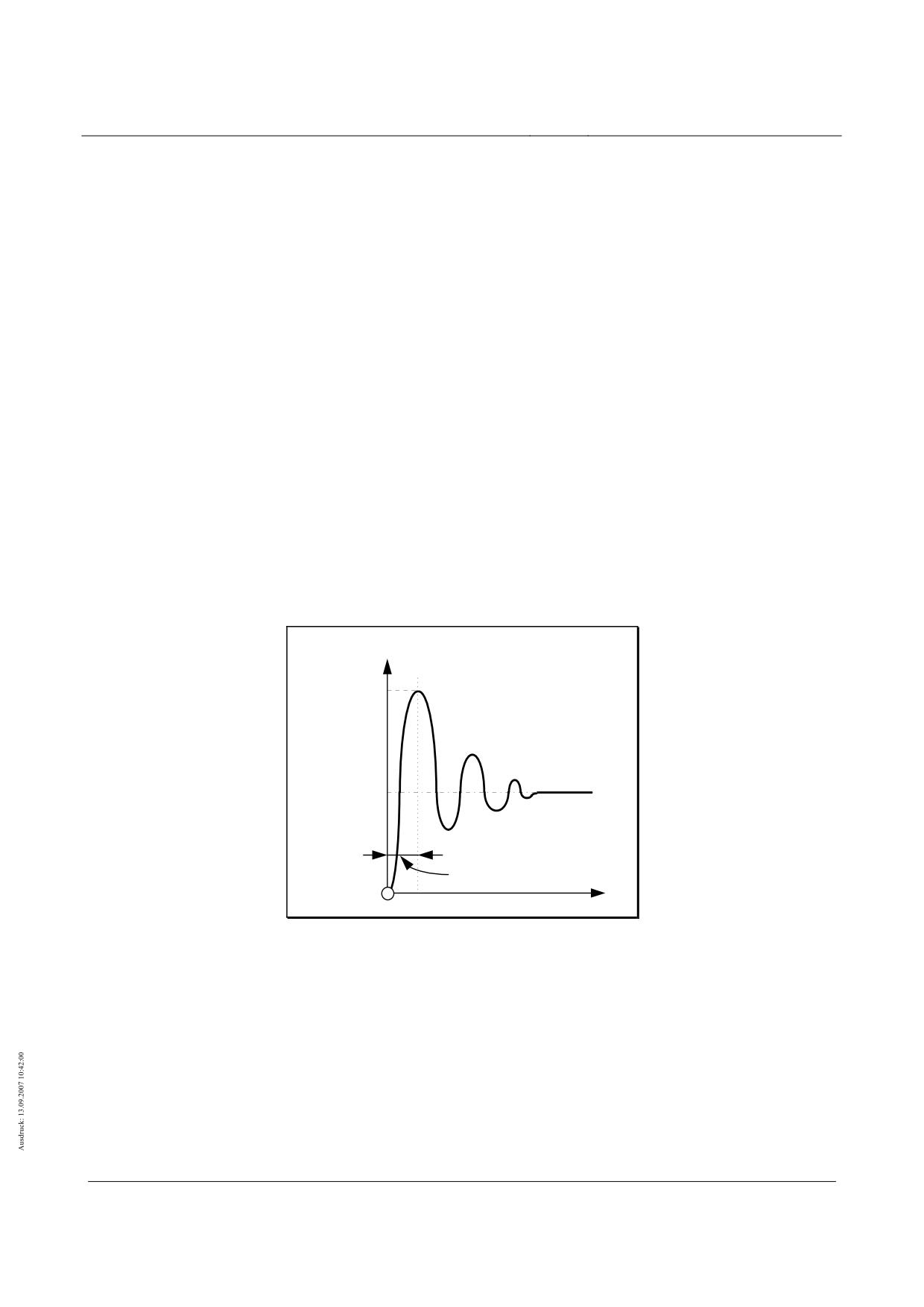
The maximum value is limited to 100kN by the vehicle for the most unfavourable situation. The dy-
namic effects can be proved e.g. with the help of the force time course following figure 134.
(3)
The associated power in x-direction from the above impact force and the maximum friction coefficients
following table 98 is to be applied as follows:
• from impact force (with µTK-GL = 0,30)
max Fx,TK,Stoß = 30 kN
• from quasi-static load (with µTK-GL,Haft = 0,50) max Fx,TK,stat = 25 kN
(4)
The friction coefficient may be reduced with the minimum location dependent travel speed following
table 98 being taken into account.
(5)
As a consequence of friction between support skid and sliding plane the support skid heats up. The
maximum amount of heat stored in the sliding surfaces of the support skid amounts to 650kJ. With a
stopping vehicle this leads to heating of the sliding strip/sliding plane in the area of the support skid.
The resultant temperature increase is to be established dependent on the design.
Fz
max Fz,TK,Stoß
= 100 kN
max Fz,TK,stat
= 50 kN
10...15 ms
t
Figure 134 - Typical force-time course of the dynamic support skid force
(6)
The local deformations as a consequence of the impact load are to be established. The verification of
compatibility to the vehicle is to be shown for the deformations to be expected.
(7)
The surface loads are to be established as follows with the dimensions in figure 125 being taken into
account:
max qz,TK = max Fz,TK / (LTK ⋅ bTK) max qz,TK = max Fz,TK / (LTK ⋅ bTK)
( 22)
max qx,TK = µ ⋅ max Fz,TK / (LTK ⋅ bTK)max qx,TK = µ ⋅ max Fz,TK / (LTK ⋅ bTK)
( 23)
(8)
For global proofs replacement loads may be applied in place of the above value limits of the support
skid forces which result from the global actions following chapter 0.
Title
High-speed Maglev Systems - Design principles
Guideway - Part II: Design
Doc. no.:
57288
Version
White Paper Issue date
15.02.2007
Page 72
High-speed maglev systems
Maglev Technical Committee
Design principles
Guideway
Failure of a guidance magnet circuit (Q11d)
(1)
With failure of a magnet regulating circuit for guidance MREF the proportionate guidance force of the
failed partial magnet (see load arrangement) is transferred from the neighbouring partial magnet of the
neighbouring guidance magnet.
(2)
For local proofs the following maximum magnetic forces in y-direction are to be applied for this action
(limit capacity of the guidance magnets):
• max py,FMT = 16 kN/m for guidance magnets with magnetic poles below
• max py,FMT = 32 kN/m for guidance magnets with magnetic poles below and above
(3)
The associated load arrangement is to be taken from Figure 152 (chapter 0)
(4)
For global proofs replacement loads may be applied in place of the above value limits of the guidance
magnet forces which result from the global actions following chapter 0.
Failure of neighbouring support magnet circuits (Q11e)
(1)
With failure of both magnet regulating circuits on one levitating framework the start strips of the guid-
ance magnets opposite transfer the proportionate guidance forces to the lateral guidance rails me-
chanically (compressive force).
(2)
The maximum local impact force on the lateral guidance rails (incl. local component dynamics) is to be
applied as follows for local proofs:
• max Fy,FM,Q11e1 =
63 kN (with γF =1,35) without wind
• max Fy,FM,Q11e2 = 115 kN (with γF =1,00) 22 with wind (vW = 25 m/s)
(3)
The action Fy,FM,Q11e2 is to be classified as “accidental action” with reference to the probability of oc-
currence.
(4)
The associated maximum power in x-direction is to be established from the above impact force and
the maximum friction coefficient of µFM,SFS = 0,3 at v ⇒ 0 km/h as follows:
max Fx,FM = µFM_SFS ⋅ max Fy,FM
( 24)
(5)
The coefficient of friction may be reduced, taking into consideration the local minimum operating ve-
locity in accordance with Tabelle 97 .
(6)
The geometry of the action is to be taken from Figure 153.
(7)
The temperature increase as a consequence of mechanical guiding (start up) is covered by the action
from the safe brake.
(8)
For global proofs replacement loads may be applied in place of the above value limits of the start up
forces of the guidance magnet which result from the global actions following chapter 0.
22 If the serviceability and safety are not affected inadmissibly, local plastic deformations with the
application of max Fy1FMQ11e2 can be permitted in agreement with the responsible inspectorate.
Title
High-speed Maglev Systems - Design principles
Guideway - Part II: Design
Doc. no.:
57288
Version
White Paper Issue date
15.02.2007
Page 73
High-speed maglev systems
Maglev Technical Committee
Design principles
Guideway
•
Use of the vehicle "safe brake" (Q11f)
Rule
If the braking system (long stator motor) fails, the vehicle safe brake is activated (for the geometry and posi-
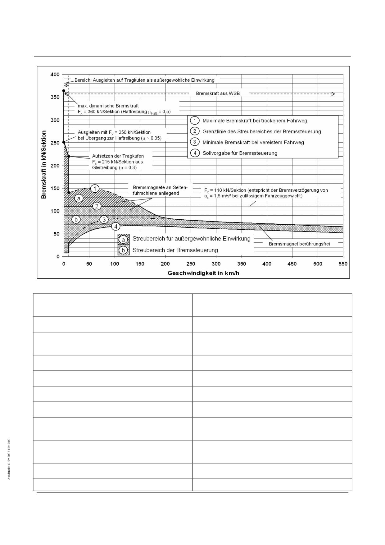
tioning of the braking magnets on the vehicle see Figure 124). The braking process is divided into two
sections according to the actions on the guideway (see Figure 137):
• Section I:
Non-contact application of the eddy-current braking force ("free" braking magnet)
• Section II: Applying the braking magnets to the lateral guidance rails
In the case of an empty vehicle, the braking forces may be reduced in accordance with the lower mass in the
ratio of the dead weight of the vehicle to its permitted total weight (see chapter 0).
For section I (≈200 km/h ≤ vVeh ≤ 530 km/h) the following actions must be taken into account:
Non-contact application of the eddy-current braking force Fx,BM,, whereby the magnetic force increases as the
velocity decreases:
max Fx,BM,I
= 63 kN/section ... ≈ 85 kN/section 23
The accompanying magnetic tensile force py,BM,I on the lateral guidance rails, which takes effect as an "inner
force" similar to the prestressing force of the guidance magnet, taking into account the tolerances and
range, amounts to:
max py,BM,I ≤
37.5 kN/m
For the support magnets near the eddy-current brakes, an uneven distribution of the support magnet force of
around 30% must be set, as shown in Figure 148. This combination must also be considered in the
following braking section II.
In section II (0 km/h < vFzg < ≈200 km/h) the following actions must be taken into account:
At vFzg < ≈200 km/h the braking magnets are applied to the lateral guidance rails. The amount of acting fricti-
onal force in the x-direction, together with the decreasing magnetic braking force is limited to a maxi-
mum braking force, max Fx,BM,II of:
max Fx,BM,II ≤ 110 kN/section
The maximum tensile force in the y-direction max py,BM,II is: max py,BM,II = 37.5 kN/m
Compressive force does not occur in the y-direction. When using max py,BM,II, ϕRl = 1.0 can be used.
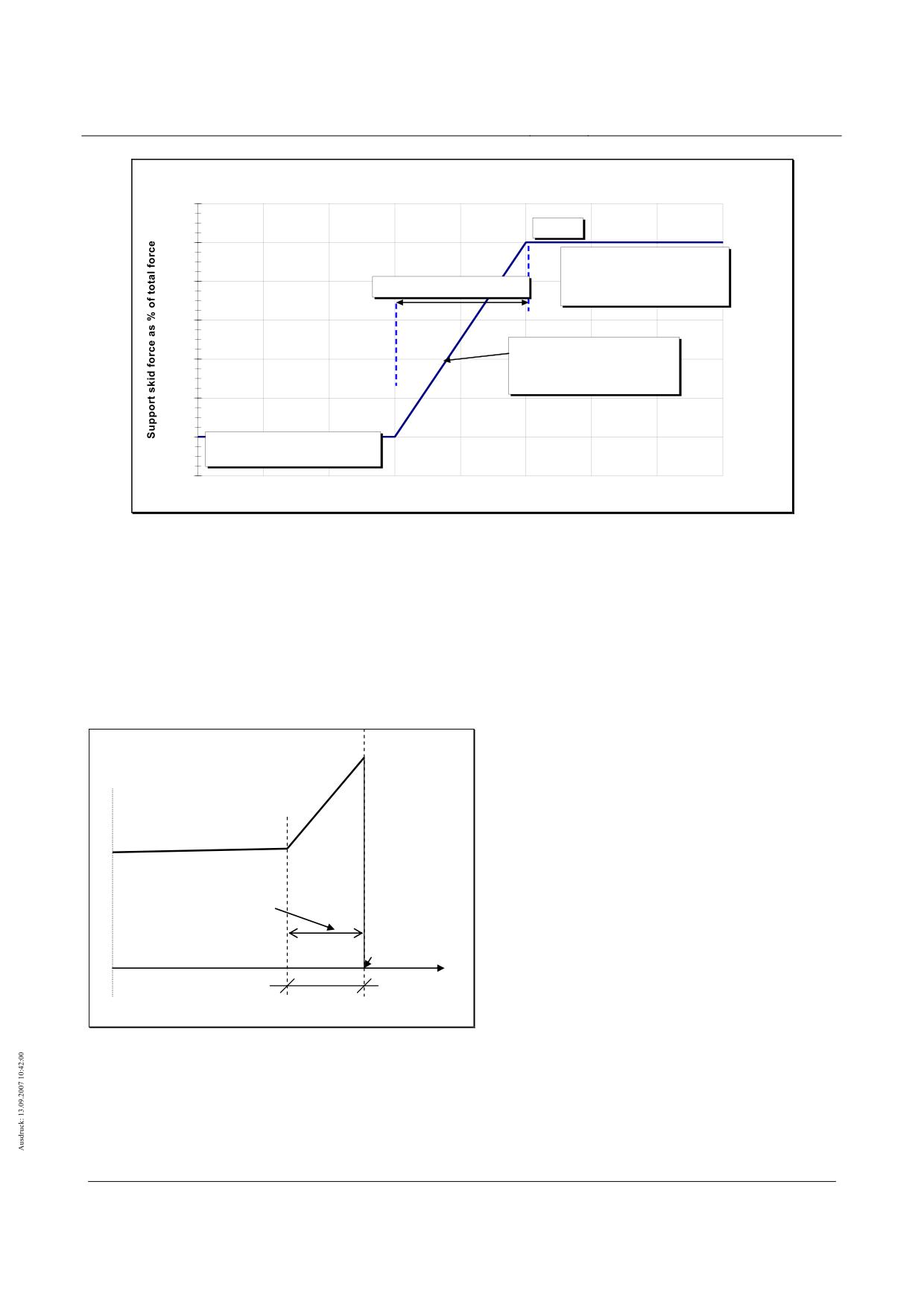
At vVeh = 5 km/h the set-down command comes into force and the vehicle is set down on the guideway in a
controlled manner. As the support skids are lowered onto the sliding surfaces, the vehicle’s velocity
vFzg = 0 km/h. The support skids’ strength can be determined in a similar manner to that in chapter 0,
taking the corresponding vibration coefficient into consideration. The time function of the controlled set
down of the vehicle is shown in Figure 135. This must be taken into account when verifying the dyna-
mics in the x- and z-directions.
The increase in temperature on the lateral guidance rails caused by the braking magnets must be set at
∆TBM_SFS ≤ 8 K for a 10 section vehicle. This temperature increase must be superimposed with the en-
vironmental thermal actions in accordance with chapter 0.
The load arrangement for the braking magnets must be taken from Figure 154.
As with braking and acceleration via the long stator, the overturning moment occurs around the y-axle when
the "safe brake" is applied. The resulting z-force distribution must be taken into account.
23 Intermediate values may be added linearly.
Title
High-speed Maglev Systems - Design principles
Guideway - Part II: Design
Doc. no.:
57288
Version
White Paper Issue date
15.02.2007
Page 74
High-speed maglev systems
Maglev Technical Committee
Design principles
Guideway
Controlled vehicle set-down on the support skids
120
100 %
100
Loaded support skids
when support skids are
80
Set-down time
0.5 ..2 s
set down
60
Increase of force in the
40
support skids during
controlled set down
20
0
Unloaded support skids
/
-20
Tim e [s]
Figure 135 - Typical, simplified time function of controlled vehicle set down
Special cases
When the braking power of the braking magnets (see Figure 137: line 1), the slide vVeh ⇒ 0 of a vehicle with
permitted weight placed on the support skids (see Figure 137: area vveh < 10 km/h) and γQ = 1.0 is ex-
ceeded, this must be considered as an accidental design situation.
For these special cases, when designing the guideway observe the time lapse provided in the following Figu-
re 136 for the acceleration ax during the transition from sliding to static friction.
µHaft= 0.5
µGleit= 0.3…0.35
Transition region
Sliding to static friction
vFzg= 0 km/h
t
0.10 s … 0.25 s
Figure 136 - Typical acceleration time function for sliding on the support skids
Title
High-speed Maglev Systems - Design principles
Guideway - Part II: Design
Doc. no.:
57288
Version
White Paper Issue date
15.02.2007
Page 75
High-speed maglev systems
Maglev Technical Committee
Design principles
Guideway
Figure 137 - "Safe brake" braking force progression
Bereich: Ausgleiten auf Tragkufen als außergewöhnliche
Area: Sliding on support skids as accidental action
Einwirkung
Bremskraft aus WSB
Braking force from WSB
Max. dynamischer Bremskraft Fx = 360 Kn/Sektion
Max. dynamic braking force Fx = 360 Kn/section (static
(Haftreibung)
friction)
Maximale Bremskraft bei trockenem Fahrweg
Maximum braking force on a dry guideway
Grenzlinie des Streubereiches der Bremssteuerung
Limit of the range of dispersion of the braking control
Minimale Bremskraft bei vereistem Fahrweg
Minimum braking force on icy guideway
Sollvorgabe für Bremsteuerung
Target values for braking control
Ausgleiten mit Fx = 250 kN/Sektion bei Übergang zur
Sliding at Fx = 250 Kn/section during transition to static
Haftreibung
friction
Aufsetzen der Tragkufen Fx = 215 kN/Sektion aus Gleit-
Setting down of the support skids Fx = 215 Kn/section
reibung
from sliding friction
Bremsmagnete an Seitenführschiene anliegend
Braking magnet placed on lateral guidance rail
Fx = 110 Kn/Sektion (entspricht der Bremsverzögerung
Fx = 110 Kn/section (corresponds to brake retardation
Title
High-speed Maglev Systems - Design principles
Guideway - Part II: Design
Doc. no.:
57288
Version
White Paper Issue date
15.02.2007
Page 76
High-speed maglev systems
Maglev Technical Committee
Design principles
Guideway
von Ax = 1.5 m/s² bei zulässigem Fahrzeuggewicht)
of Ax = 1.5 m/s² with permissible vehicle weight)
Streubereich für außergewöhnliche Einwirkung
Range of dispersion for accidental action
Streubereich der Bremssteuerung
Range of dispersion of the braking control
Bremsmagnet berührungsfrei
Contactless braking magnet
Geschwindigkeit in km/h
Velocity in km/h
Bremskraft in kN/Sektion
Braking force in kN/section
Velocity deviations (Q11g)
Actions resulting from velocity deviations (e.g. stationary vehicles outside stations or slow moving vehicles
on 12° guideway transverse gradients (ay ⇒ 2.04 m/s²)) must be regarded as infrequent variable ac-
tions in comparison to frequent variable actions (for more information regarding this see chapter 0).
Title
High-speed Maglev Systems - Design principles
Guideway - Part II: Design
Doc. no.:
57288
Version
White Paper Issue date
15.02.2007
Page 77
High-speed maglev systems
Maglev Technical Committee
Design principles
Guideway
Propulsion system failure (Q11h)
One-sided propulsion system failure
The "one-sided propulsion system failure" malfunction must be considered as described and covered in
chapter 0 (actions relating to motor section switching during the alternating step method).
Other propulsion system malfunctions
In the case of unfavourable side-selective unequal distribution 0.73/0.27, a maximum thrust of Fx,Q11h1,HG =
185 kN/middle section should be taken into account24. This results in the following forces on each side
of the guideway:
max px, Q11h1, HG, right/left = 0.73 ⋅ 185 kN / 24.768 m = 5.5 kN/m
min px, Q11h1,HG, left/right = 0.27 ⋅ 185 kN / 24.768 m = 2.0 kN/m (without dynamic force)
When there are equally effective, maximum resulting actions in the x-direction on both guideway sides in the
event
of
malfunction,
take
into
consideration
the
following
force:
px,Q11h2 = 250 kN / middle section = 250 kN / 24.768 m = approx. 10.0 kN/m
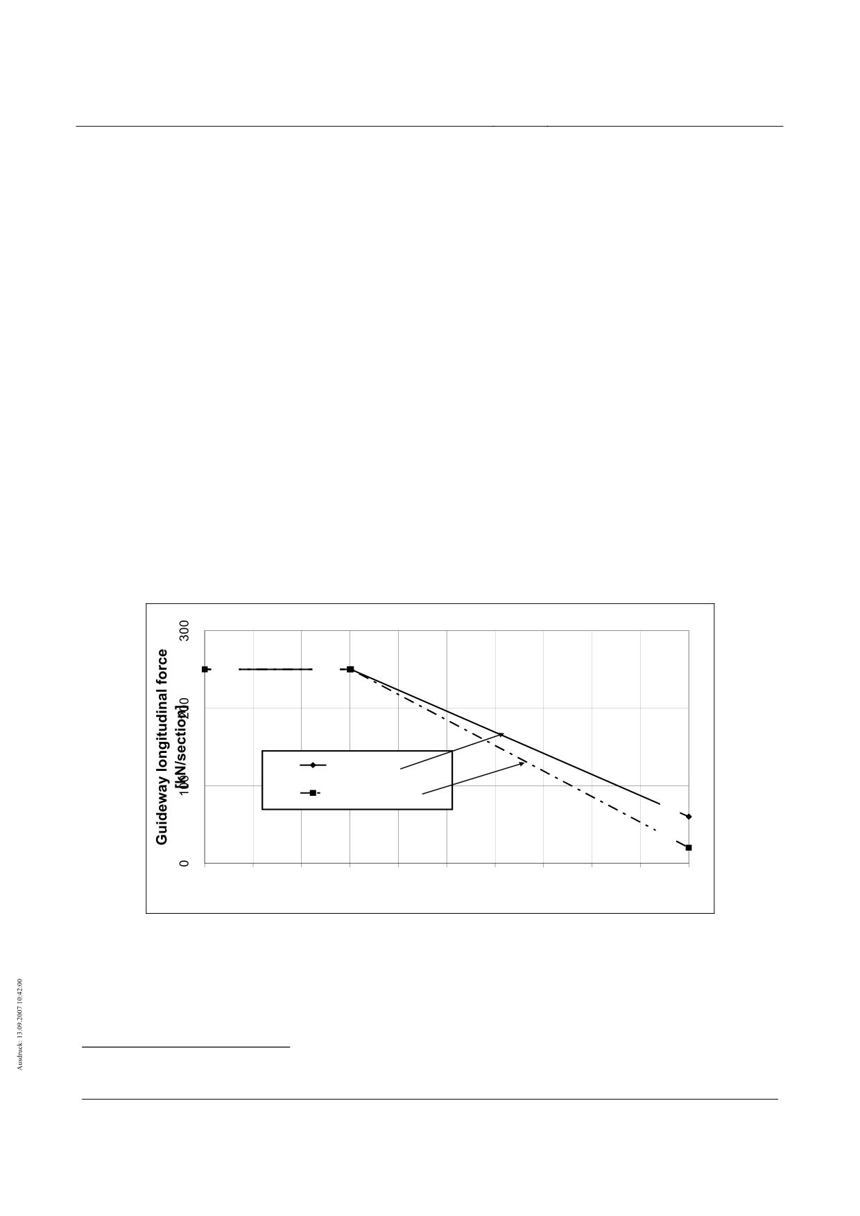
A typical (simplified) function of the action dependent on velocity and vehicle length (number of sections) as
a result of propulsion system malfunction is shown as an example on Figure 138. In the case of pro-
ject independent verification, the specified reduction must be applied.
With regard to probability of occurrence, the action px,Q11h2 must be considered unusual (γQ = 1.0).
Whether it is necessary to consider these actions and the scale of the reduction depends on the project and
must always be confirmed on a case by case basis.
Forces resulting from pitching moments must be taken into consideration as in chapter 0
250
250
2 Sections
>= 7 Sections
60
20
0
50
100
150
200
250
300
350
400
450
500
Travelling velocity [km/h]
Figure 138 - Velocity function of the x-forces as a result of propulsion system malfunction
One-sided set-down of the vehicle (Q11i)
General
24 The actions for the other vehicle weights are: Fx,Q11h1,ZG = 180 kN/middle section, Fx,Q11h1,MG = 170
kN/middle section and max Fx,Q11h1,EG = 150 kN/middle section
Title
High-speed Maglev Systems - Design principles
Guideway - Part II: Design
Doc. no.:
57288
Version
White Paper Issue date
15.02.2007
Page 78
High-speed maglev systems
Maglev Technical Committee
Design principles
Guideway
In the event of a short circuit of the long stator winding, the two following design situations must be conside-
red with regard to the actions on the guideway.
Design situation 1
There is a short circuit on the windings, the vehicle is above the location of the short circuit, which is near to
the winding star point (motor section switching) and the velocity is v ≥ 25 km/h. This results in the ve-
hicle being set-down on one side on the sliding surface of the guideway beams. The support skids
come into contact with the gliding strips one after the other. The side of the vehicle opposite the short
circuit continues to levitate.
Taking the vehicle weight into consideration, the unilateral section loads qz,set and qz,fun will be as follows:
• Set down side:
( 25)
qz,Q11i,set. = 0.5 ⋅ stat pz ⋅ az /g
• "functional" (levitating) side:
( 26)
qz,Q11i,fun. = 0.5 ⋅ stat pz ⋅ az / g
Other actions (e.g. centrifugal force) must be superimposed according to chapter 0. The skid forces on the
set down side must be calculated using ex,SS = support skid centre distance, as follows:
( 27)
Fz,SS,Q11i = qz,Q11i,set ⋅ ex,SS
The velocity-dependent coefficient of friction can be found in Table 98.
An additional vibration coefficient of max. ϕB,z,Q11i = 1.8 must be taken into account for the set down side.
Determine the vibration coefficient in the z-direction with a min. of ϕB,z,Q11i = 0.9 for the functioning op-
posite side.
The effect from the propulsion system may be positive (braking), negative (acceleration) or zero in accordan-
ce with chapter 0.
The different forces in the x-direction on both the functional and set down side cause a moment to act on the
z-axle. This moment ensures that the forces on the lateral guidance rails (y-direction) are balanced.
The guidance magnet forces act in a similar manner to that described in chapter 0. The remaining ac-
tions in the y-direction must be determined in a similar way to the frequent actions.
Only take into account the combination that has the vehicle weight as the leading variable action.
Design situation 2
The short circuit location is not near the cable winding star point or the vehicle has travelled over an already
existing short circuit.
This design situation has an effect on the short circuit side on the support magnet/long stator interface bra-
king force, which is globally covered by the x-forces from a) and locally covered by the x-forces from
Q11b.
Activating/contact with magnets (Q11j)
Support magnets
The vehicle-side minimum gap monitoring prevents a force-induced activation of the support magnets on the
stator packs.
Potential activation due to interference as a result of unfavourable boundary conditions (guideway toleran-
ces, state of motion and load status of the support magnet) is covered by the actions listed in chapter
0.
Guidance magnets
Title
High-speed Maglev Systems - Design principles
Guideway - Part II: Design
Doc. no.:
57288
Version
White Paper Issue date
15.02.2007
Page 79
High-speed maglev systems
Maglev Technical Committee
Design principles
Guideway
If the ultimate bearing capacity of the guidance magnets is exceeded as described in chapter 0, this may
lead to contact with the guidance magnets positioned opposite.
Actions caused by contact with guidance magnets are described in chapter 0 "Failure of neighbouring sup-
port magnet circuits (Q11e)".
Raising frozen support skids (Q11k)
The tension and thrust created by releasing a frozen support skid is transferred to the supporting structure
via the gliding strips.
The maximum actions caused by raising frozen support skids are applied locally using the following forces:
• Tension in z-direction
Fz,Q11k =
50.0 kN / skid
• Thrust in x-direction Fz,Q11k = 25.0 kN / skid
It is unwise to assume that the locally assigned support magnets on the frozen support skid do not receive
any of the force (see chapter 0).
Increase in vehicle weight due to snow (Q11l)
Take into account that snow accumulation on the vehicle increases the section load, using the following va-
lues:
• ∆pZ,EG,Q11l(1) = 1.6 kN/m → infrequent
• ∆pZ,EG,Q11l(2) = 3.2 kN/m → accidental
The frequency of occurrence and the characteristic values to be applied must be determined on an individual
basis (see also /MSB AG-FW IH/; reference carrier, monitoring).
The centroidal distance of the snow accumulation in the z-direction must be set at sz,Q11l = 400 mm.
Actions resulting from maintenance (Q30)
Action effects including potential dynamic step-ups resulting from maintenance (incl. the associated special
vehicles, devices and payloads) must not be measured.
Title
High-speed Maglev Systems - Design principles
Guideway - Part II: Design
Doc. no.:
57288
Version
White Paper Issue date
15.02.2007
Page 80
High-speed maglev systems
Maglev Technical Committee
Design principles
Guideway
Environmental temperature (Q50)
General
/DIN technical report 101/chapter V describes the rules and procedures for the determination of thermal ac-
tions on bridges, including their sections. The characteristic values of the actions, as far as they are
applicable to the guideway elements of the high-speed Maglev system, can be taken from there. It
does not include application-dependent thermal actions.
The following will be referred to:
• Thermal fluctuation: a regular change in the centroidal temperature of all components (see /DIN
technical report 101/chapter V, 6.3.1.3)
• Linear temperature difference: linear thermal gradient between opposite edges of components
(see /DIN technical report 101/chapter V, 6.3.1.4)
• Uneven heating of components: a jump (thermal difference) between the centroidal temperature of
individual components, which are not joined together and/or are made of different types of material
(see /DIN technical report 101/chapter V, 6.3.1.6)
The thermal expansion coefficient for the components must be taken from /DIN technical report 101/.
Thermal fluctuations in the guideway superstructure (Q50a)
If the min. and max. outside air temperature cannot be determined more exactly, then the typical values gi-
ven in Table 110 (column 1) can be used for central European projects. These refer to outside air
temperatures between -24°C and +37°C over a period of 50 years.
When calculating the bearing play and (expansion) joints increase the values in Table 110 by 25%.
The possibility of reducing the actions described in Table 110 must be agreed upon on an individual basis
with the responsible inspectorate.
Linear temperature difference (Q50b)
General
The temperature differences that need to be taken into account are, among other things, dependent on the
condition of the surface, the geometry and climatic conditions.
The following symbols apply to the subsequent threshold values:
∆TM
linear temperature difference To - Tu or Tl - Tr
To
Top chord temperature
Tu
Bottom chord temperature
Tl
Temperature of the left edge of the load-bearing cross section
Tr
Temperature of the right edge of the load-bearing cross section
(For full cross sections use the values on the cross section edge for To and Tu.)
Title
High-speed Maglev Systems - Design principles
Guideway - Part II: Design
Doc. no.:
57288
Version
White Paper Issue date
15.02.2007
Page 81
High-speed maglev systems
Maglev Technical Committee
Design principles
Guideway
Guideway superstructure
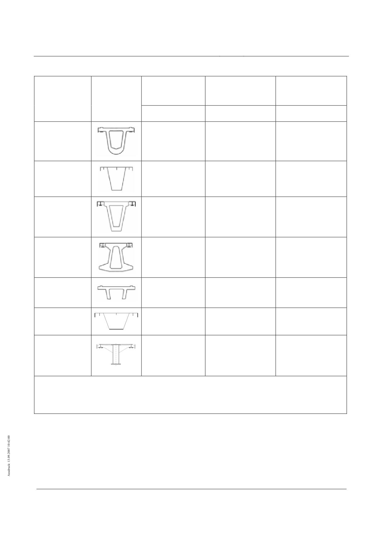
Characteristic values for linear temperature differences for various types of bridge superstructure and varying
bridge surface thicknesses can be found in /DIN technical report 101/chapter V, 6.3.1.4. These values
are upper limit values for the linear temperature differences for typical examples of the bridge geo-
metry of roads and railway bridges.
The following guidelines must also be considered for the high-speed Maglev system’s guideway beams:
• Guideway type I and II
For discretely supported guideway beams, the characteristic values provided in Table 110 (column
2) can be used, if their cross section and surface is similar. Check the suitability of these values
for each individual case with the responsible inspectorate.
• Guideway type III and other guideway designs
For guideway plate systems and other guideway constructions that are not covered by the values
provided in Table 110, then the values are to be agreed upon with the responsible inspectorate (if
necessary by theoretical investigation on the basis of calculation simulations).
• Guideways in tunnels
In the case of guideways in tunnels, there is generally no need to apply a temperature difference
as a result of environmental factors.
• Track switching equipment
see Table 110
To ensure an optimal guideway position in peak periods, (this is to be determined on an individual project
basis), when determining the supporting theoretical position, take into account an expected linear
temperature difference T0 - TU for this period, during the determination of the theoretical pre-curve.
This temperature difference results in an optimal guideway position (i.e. the guideway position cor-
responds to the guideway gradient when the vehicle is on it).
For cross sections not covered in Table 110, hypotheses for the temperature scales must be determined in
cooperation with the responsible inspectorate with reference to Table 100 and any other experience or
findings. If necessary, these hypotheses must be proven by measurements.
Guideway substructures
Environmental thermal actions for guideway substructures can be found in /DIN technical report 101/chapter
V, 6.3.2.
Uneven heating of components due to environmental factors (Q50c)
Set ∆T = ± 15 K as the temperature difference between steel and concrete parts for the cases described in
/DIN technical report 101/chapter 6.3.1.6.
With steel and concrete components that are connected by an entire surface (e.g. LGR or SS on concrete
girders) use temperature differences of ∆T = ± 10 K when lower temperatures have not been verified.
The uneven heating mentioned above is to be superimposed on components, whose temperature increases
as a result of traffic.
Title
High-speed Maglev Systems - Design principles
Guideway - Part II: Design
Doc. no.:
57288
Version
White Paper Issue date
15.02.2007
Page 82
High-speed maglev systems
Maglev Technical Committee
Design principles
Guideway
Linear temperature
Linear temperature
Thermal fluctua-
difference ∆Tz,My
difference ∆Ty,Mz lat-
Construction
tion TN
Cross section
vertical [K]
eral [K]
method
1
2
3
Concrete con-
struction
-15 °C ≤ TN ≤ 35 °C
-5 ≤ ∆Tz,My ≤ 17
-10 ≤ ∆Ty,Mz ≤ 10
(Height: 2 m)
Steel construction
-20 °C ≤ TN ≤ 50 °C
-5 ≤ ∆Tz,My ≤ 25
-17 ≤ ∆Ty,Mz
≤ 17
(Height: 2 m)
Hybrid construc-
tion I
-15 °C ≤ TN ≤ 35 °C
-5 ≤ ∆Tz,My ≤ 15
-10 ≤ ∆Ty,Mz ≤ 10 *
(Height: 2 m)
Hybrid construc-
tion II
-15 °C ≤ TN ≤ 35 °C
-5 ≤ ∆Tz,My ≤ 10
-10 ≤ ∆Ty,Mz ≤ 10 *
(Height: 2.2 m)
Concrete con-
struction
-15 °C ≤ TN ≤ 35 °C
-5 ≤ ∆Tz,My ≤ 17
-5 ≤ ∆Ty,Mz ≤ 5
(Height: 1 m)
Steel construction
-20 °C ≤ TN ≤ 50 °C
-8 ≤ ∆Tz,My ≤ 25
-13 ≤ ∆Ty,Mz ≤ 13
(Height: 1 m)
Flexible steel
(bendable girder
-20 °C ≤ TN ≤ 50 °C
-10 ≤ ∆Tz,My ≤ 20
-10 ≤ ∆Ty,Mz ≤ 10
WxH: 0.45 m x
1.5 m)
The characteristic values provided for the thermal actions were determined according to the information
given in /DIN technical report 101/, the theoretical calculation results in /R 1/ and the measurement results
from TVE.
* on the supporting concrete cross section
Table 110 - thermal fluctuations and linear temperature differences
Title
High-speed Maglev Systems - Design principles
Guideway - Part II: Design
Doc. no.:
57288
Version
White Paper Issue date
15.02.2007
Page 83
High-speed maglev systems
Maglev Technical Committee
Design principles
Guideway
Effect of wind on the supporting structure (Q51)
Effect of both wind and traffic on the supporting structure (Q51)
Assess wind actions in conjunction with traffic on the supporting structure as described in /DIN technical
report 101/.
It is assumed that the guideway is not susceptible to vibration with regard to wind actions, otherwise more
exact verification is required.
Assume the wind direction is horizontal.
In the case of double track guideways, measure the individual tracks for the full wind load from both directi-
ons.
In the case of wind and traffic acting on the supporting structure, only the area of the guideway not covered
by the vehicle is used as the wind exposed surface.
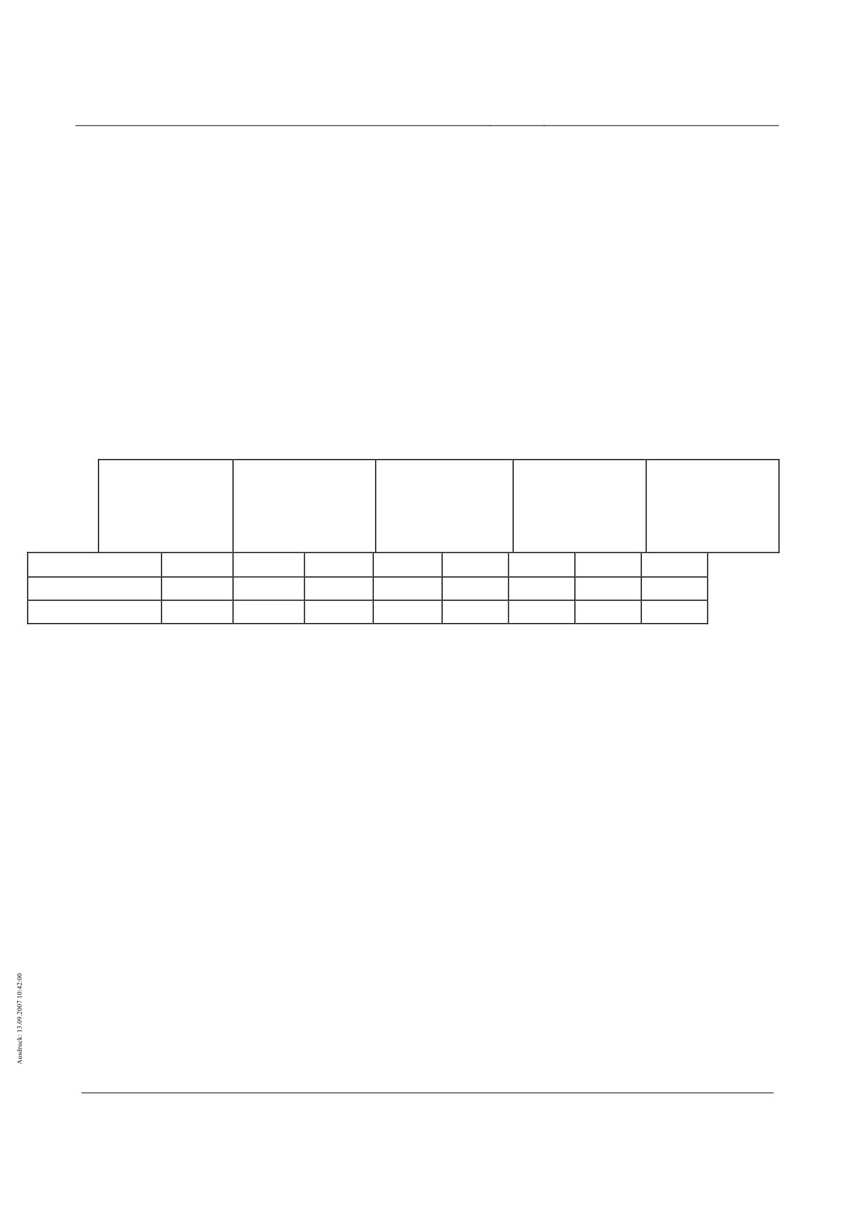
The dynamic pressure to be considered for the nominal wind gust velocity vb,10 (5 second average, once a
year) in wind zones I, II,III and IV for various gradients across ground must be taken from Table 111.
Form factors and other factors for determining the size of the action on the supporting structure caused by
wind must be taken from the existing regulations of the relevant structure.
WZ II
WZ II
WZ I
WZ IV
Gradient height
vW
qW,supporting
vW
qW,supporting
vW
qW,supporting
vW
qW,supporting
hG,ground
structure
structure
structure
structure
[m/s]
[kN/m²]
[m/s]
[kN/m²]
[m/s]
[kN/m²]
[m/s]
[kN/m²]
≤ 4.0 m
25
0.40
28
0.50
32
0.65
36
0.80
> 4.0 m … 13.0 m
28
0.50
31
0.60
36
0.80
40
1.00
> 13.0 m … 20.0 m
29
0.55
33
0.70
37
0.85
42
1.10
Table 111 - dynamic pressure qW,supporting structure on the supporting structure
Effect of wind without traffic on the supporting structure (Q51)
Verify wind actions without traffic on the supporting structure in accordance with the /DIN technical report
101/.
It is assumed that the guideway is not susceptible to vibration with regard to wind actions, otherwise more
exact verification is required.
Snow and ice loads (Q52)
With
traffic:
The assumed snow depth with traffic is 10 cm. Take into account an area load of qsnow = 0.5 kN/m²,
this corresponds to assuming a unit weight of 5 kN/m³ (wet snow).
Without
traffic:
For snow without traffic use the values in /DIN technical report 101/. For the guideway beams, this ac-
tion combination is covered by traffic actions.
Variable water pressure forces (Q53)
•
Variable water pressure forces must be taken into account as appropriate for local cir-
cumstances.
Title
High-speed Maglev Systems - Design principles
Guideway - Part II: Design
Doc. no.:
57288
Version
White Paper Issue date
15.02.2007
Page 84
High-speed maglev systems
Maglev Technical Committee
Design principles
Guideway
Wind load in construction stages (Q54)
Wind actions in construction stages must be regarded as variable actions on the basis of /DIN
technical report 101/.
Maintenance conditions (Q55)
Actions resulting from maintenance conditions or similar conditions (e.g. due to raising the suppor-
ting structure to replace bearings and bearing parts) must be taken into account.
Construction stages (Q56)
Actions as a result of construction and assembly stages must be considered when dimensioning the suppor-
ting structure.
In order the take into account the actions as a result of the assembly of the stator packs and the long stator
winding, the following actions must be applied locally for the verification of the stator packs and their
attachment to the guideway structure:
dyn pz = - 5.0 kN/m
dyn px = 5.0 kN/m
Actions on track switching equipment (Q57)
Elastic bending of deflection switches (Q57a)
Calculate the flexural tensile stresses from forced bending of the deflection switches and the ad-
justment forces using the elastic deflection curve of the relevant switch.
Actions resulting from the propulsion system (Q57b)
Take into consideration actions resulting from the inertia, friction and asynchronism of the location
of the track switching equipment drive system (deflection switches, travelling platforms).
Displacement resistance of bearings (Q58)
Actions from bearing friction must be considered in accordance with the legal construction regulati-
ons.
Failure of supporting structure elements (Q59)
It must be verified that the guideway will remain fit for traffic for a defined amount of time in the event of failu-
re of the supporting structure elements.
The measures required for this (e.g. redundancy) and the verification process must be agreed upon with the
responsible inspectorate.
Lateral earth pressure from variable actions (Q60)
•
Lateral earth pressure from variable actions must be considered in accordance with the ge-
nerally accepted technical rules and standards.
Title
High-speed Maglev Systems - Design principles
Guideway - Part II: Design
Doc. no.:
57288
Version
White Paper Issue date
15.02.2007
Page 85

High-speed maglev systems
Maglev Technical Committee
Design principles
Guideway
Accidental actions
General
The strategies and regulations for protecting the structural works of the guideway from identifiable and non-
identifiable accidental actions can be found in the appropriate standards and regulations (e.g. EN
1991).
Accidental actions resulting from the vehicle
Actions as a result of loading gauge violations (A1)
Provided that the measures on how to avoid loading gauge violations described in /MSB AG-GESAMTSYS/
are taken into account, actions as a result of loading gauge violation by the vehicle do not need to be
explored.
Safety wind load on the vehicle (A2)
An additional stability verification taking into account the hundred year wind ("safety wind load") must be
carried out for the operating situation "guideway with stationary vehicle". The safety wind load on the
vehicle must be applied using the following nominal wind gust velocities vb,10 (5 second average) at a
height of 10 m and a probability of occurrence of once every 100 years:
• Wind zone I
vb,10 = 36 m/s
• Wind zone II
vb,10 = 40 m/s
• Wind zone III
vb,10 = 46 m/s
• Wind zone IV
vb,10 = 52 m/s
The buoyancy forces on the vehicle that result from the wind velocity must be taken from Table 112. The
actions must be determined in accordance with chapter 0.
The guidance magnet forces py,SW,FMTi and the accompanying forces from the moment around the x-axle
must be determined in a similar manner to that described in chapter 0 and annex II-E.
Gradient height
Gradient height
Gradient height
Actions in kN/m
h
G,ground
≤ 4.0 m
4.0 m < hG,ground ≤ 13.0 m
13.0 m < hG,ground ≤ 20.0 m
pz,SA,1
-1.8
-1.9
-2.2
Wind zone I
p
z,SA,2
-1.1
-1.1
-1.4
pz,SA,1
-2.2
-2.3
-2.7
Wind zone II
p
z,SA,2
-1.4
-1.4
-1.7
pz,SA,1
-2.8
-3.1
-3.6
Wind zone III
p
z,SA,2
-1.7
-1.9
-2.3
pz,SA,1
-3.6
-3.9
-4.6
Wind zone IV
p
z,SA,2
-2.3
-2.4
-2.8
Table 112 - Typical actions from vehicle buoyancy as a result of safety wind load
Title
High-speed Maglev Systems - Design principles
Guideway - Part II: Design
Doc. no.:
57288
Version
White Paper Issue date
15.02.2007
Page 86
High-speed maglev systems
Maglev Technical Committee
Design principles
Guideway
Accidental actions resulting from maintenance (A3)
Action effects from maintenance do not have to verified for the vehicle.
In accordance with /MSB AG-FW ÜBG/, all special vehicles, devices and payloads required for maintenance
must be dimensioned so that action effects resulting from maintenance are covered by the Maglev ve-
hicle action effects.
Safety wind load on the supporting structure (A4)
Apply the wind actions according to /DIN technical report 101/ annex N.2 as the actions as a result of the
safety wind load (SW) on the supporting structure.
Possible foundation movements (A5)
Possible foundation movements must be taken into consideration in accordance with the generally accepted
technical rules and standards and the local guideway circumstances with regard to stability and servi-
ceability (see chapter 0).
Impact
General
If necessary, project specific additional verification must be carried out for the structural works of the guide-
way taking into account accidental actions as a result of an impact.
Potential measures to prevent impact and/or required verification for the consideration of impact on columns
and pillars can be found in existing regulations (e.g. /DIN technical report 101/).
Apply a vehicle impact load of at least 500 kN in the most unfavourable direction for all columns and pillars
e.g. even in areas in agricultural use. The load acts horizontally 1.25 m above the ground and must be
regarded as an accidental action. A dual-layer reinforcement design and a shattering layer are not ne-
cessary.
For all situations, the application of measures selected to prevent impact and/or required verification for the
consideration of impact with guideway beams must be carried out in accordance with the generally
accepted technical rules and standards and agreed upon with the responsible inspectorate.
Annex B of the prEN 199117:2005 contains advice on planning and implementing risk analysis.
Impact of track-guided vehicles (A6)
The requirements that must be considered regarding the impact of track-guided vehicles (railroad cars) must
be agreed upon with the responsible inspectorate.
The /DIN technical report 101/, the prEN 199117:2005, section 4.4 and the accompanying national attach-
ment contain information on verifying accidental actions resulting from impacts.
Title
High-speed Maglev Systems - Design principles
Guideway - Part II: Design
Doc. no.:
57288
Version
White Paper Issue date
15.02.2007
Page 87
High-speed maglev systems
Maglev Technical Committee
Design principles
Guideway
Road vehicle impact (A7)
Accidental actions as a result of road vehicle impact on supporting substructures and guideway superstructu-
res must be considered on the basis of EN 1991-1-7, section 4.3.
For personal safety, the guideway supports must also be measured for the following simultaneously acting,
resultant forces, in order to verify stability in the event of a road vehicle impact on guideway beams:
Resultant force in y-direction:
FY,impact,bearing = 1000 kN;
Resultant force in z-direction:
FZ,impact,bearing = -300 kN;
Set the response time of the resultant forces at 60 ms.
The resultant forces apply to discretely supported guideway beams made of steel and concrete with design
characteristics (stiffness, area density) similar to the TVE guideway beams.
The transferability of the resultant forces to other boundary conditions (guideway and vehicle data) or signs
of deviating resultant forces must be verified for the responsible inspectorate.
Observe the permissible deformations for accidental actions as a result of impact on columns and guideway
beams according to chapter 0.
Ice jam, thermal ice pressure, impact from watercraft (A8)
The actions and verification processes to apply for each individual case must be agreed upon with the
responsible inspectorate.
Accidental actions resulting from ship collisions must be taken from EN 1991-1-7, section 4.6.
Earthquakes (A9)
As a general rule, the design conditions according to the applicable technical construction regulations and
the generally accepted technical rules and standards (e.g. according to Eurocode EN 1998 "Design of
structures for earthquake resistance") can be used.
If in doubt, consult the responsible inspectorate as to which earthquake actions are to be taken into account.
Title
High-speed Maglev Systems - Design principles
Guideway - Part II: Design
Doc. no.:
57288
Version
White Paper Issue date
15.02.2007
Page 88
High-speed maglev systems
Maglev Technical Committee
Design principles
Guideway
Vehicle load arrangements
General
The following load arrangements must be applied according to the size of the structure being examined for
global and/or local verifications of the vehicle.
Global load arrangements
Inertia forces
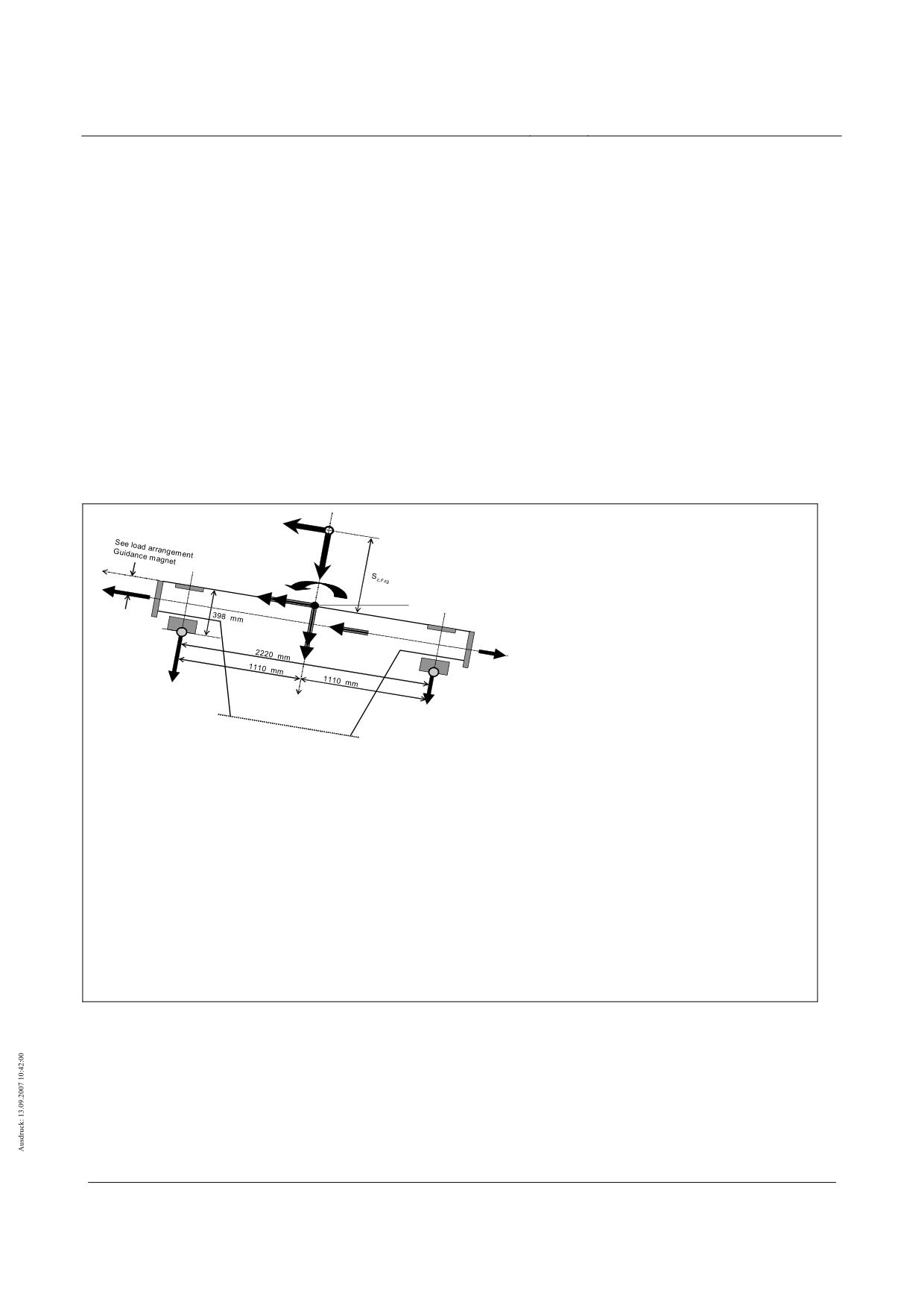
The load arrangements for the vehicle-side inertia forces (incl. dynamic lateral loads and constraint forces) in
the x-, y- and z-direction must be taken from Figure 139, Figure 143 and Figure 144 in accordance
with chapter 0
The global actions p*, px, py, pz and mx, my and mz resulting from the vehicle give rise to the interface forces
px, py, pz, Fx, Fy, and Fz.
a
y
SFzg
(Vehicle centre of gravity)
ax
y
GL
mx
az
py,r
SFS
„0“
py,my
px
x
α
GL
SP
px,r
*
py,l
py
SFS
pz,mz
SP
pz,r
px,l
z
pz,l
py* : Dynamic lateral forces and constraint
forces
• In the x-direction, take into account the magnet array lengths in accordance with chapter 0
Figure 139 - Global load arrangement for the levitating vehicle
The distribution of the inertia forces resulting from az and ay across the length of the vehicle is shown on the
following illustrations.
Determine the individual magnitudes using the equations provided.
Title
High-speed Maglev Systems - Design principles
Guideway - Part II: Design
Doc. no.:
57288
Version
White Paper Issue date
15.02.2007
Page 89
High-speed maglev systems
Maglev Technical Committee
Design principles
Guideway
Typical distribution of the support magnet force of az along the vehicle length
(1)
2
3
4
5
6
7
8
9
10 11 12 13 14 15 16
1
2
3
4
5
6
7
8
9
10 11 12 13 14 15 16
End section
Middle section
Partial magnets support TMTi
Figure 140 - Typical load arrangement for the force distribution of pz,az according to equation ( 15)
Title
High-speed Maglev Systems - Design principles
Guideway - Part II: Design
Doc. no.:
57288
Version
White Paper Issue date
15.02.2007
Page 90
High-speed maglev systems
Maglev Technical Committee
Design principles
Guideway
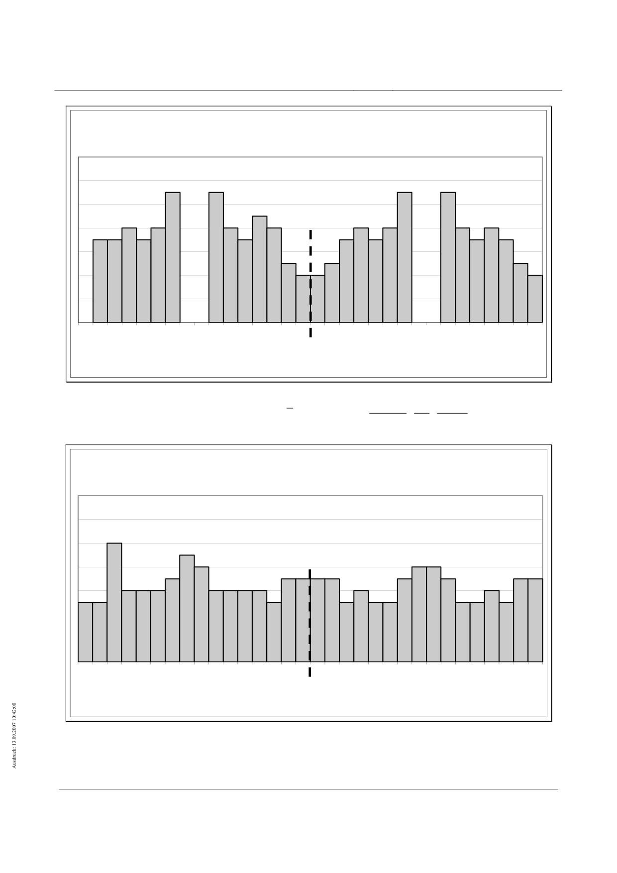
Typical distribution of the guidance magnet forces of ay across the vehicle length
BM
BM
(1)
2
3
4
5
6
7
8
9
10 11 12 13 14 15 16
1
2
3
4
5
6
7
8
9
10 11 12 13 14 15 16
End section
Middle section
Partial magnet guidance FMTi
Figure 141 - Typical load arrangement for the force distribution of py,ay according to equation
a
k
L
ES/MS
y
y,ay,i
p
y,ay,FM T
,E G / M G / Z G / H G
=
p
Z,EG/MG/ZG/HG
⋅
⋅
⋅
i
L
g
100
FMT
in [kN/m]
Typical distribution of the support magnet forces of ay across the length of the vehicle
(1)
2
3
4
5
6
7
8
9
10 11 12 13 14 15 16
1
2
3
4
5
6
7
8
9
10 11 12 13 14 15 16
End section
Middle section
Partial magnet supportTMTi
Figure 142 - Typical load arrangement for the force distribution of pz,ay according to equation ( 11)
Title
High-speed Maglev Systems - Design principles
Guideway - Part II: Design
Doc. no.:
57288
Version
White Paper Issue date
15.02.2007
Page 91
High-speed maglev systems
Maglev Technical Committee
Design principles
Guideway
SFzg
(Vehicle centre of gravity)
a
x
a
y
F
z, TK, r
*
y
Fy, TK, r
m x
az
Fx ,TK, r
F
z, TK, l
SFS
„0“
GL
py ,m
y
p
α
py ,r
x
x
GL
Fx ,TK, l
SP
*
F
y, TK, l
*
SFS
py
pz ,m z
SP
py ,l
z
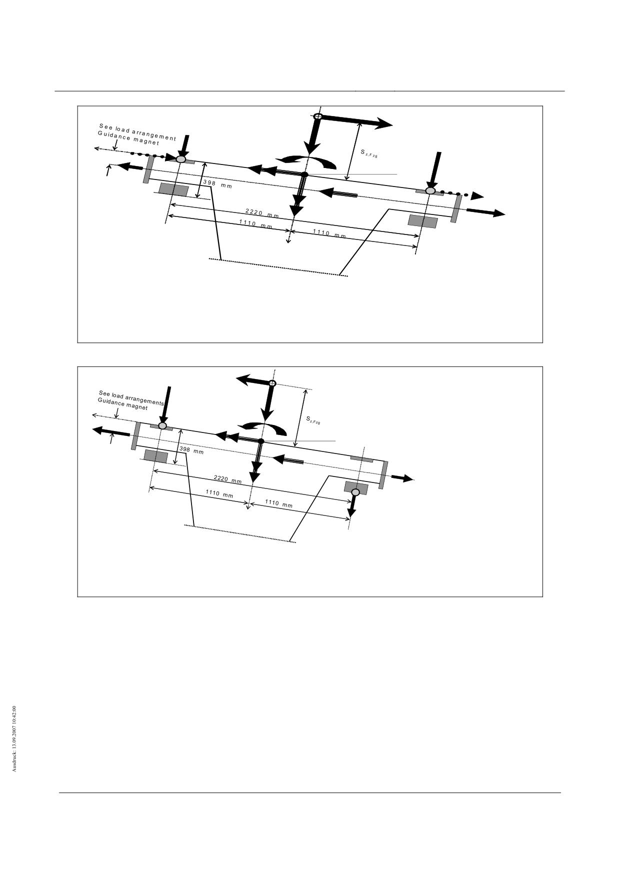
• py* : Dynamic lateral forces and constraint forces
• In the x-direction, take into account the magnet array lengths in accordance with chapter 0
• Fy, TK,r/l * act only when the guidance magnets are deactivated py, r = py, l = 0
Figure 143 - Global load arrangement for the levitating vehicle / stationary vehicle
Vehicle side setting down
a
SFzg
(Vehicle centre of gravity)
y
ax
Fz, TK, r
y
GL
F
mx
az
x, TK, r
Levitating vehicle s
py,r
SFS
„0“
py,my
px
α
x
GL
SP
py
*
SFS
py,l
pz,mz
SP
px,l
z
pz,l
• py* : Dynamic lateral forces and constraint forces
• In the x-direction, take into account the magnet array lengths in accordance with chapter 0
Figure 144 - Global load arrangement for the design situation Q11i
Title
High-speed Maglev Systems - Design principles
Guideway - Part II: Design
Doc. no.:
57288
Version
White Paper Issue date
15.02.2007
Page 92
High-speed maglev systems
Maglev Technical Committee
Design principles
Guideway
Wind on the vehicle
The load arrangement for actions as a result of "wind on the vehicle" and "buoyancy" according to chapter 0
must be taken from Figure 145.
The global actions p*, px, py, pz and mx, my und mz resulting from the vehicle give rise to the interface forces
px, py, pz, Fx, Fy, und Fz.
Uplift A
(normal to the guideway table)
Lateral wind W
SW (wind attack point)
(parallel to guideway table)
y
mx, W
SS
LGR
„0“
py,r, W
py,W
α
x
SS
SP
(py,l, W)
LGR
pz, A , mz, W
SP
pz,r, A/W
z
pz,l, A/W
• In the x-direction, take into account the magnet array lengths in accordance with chapter 0 and the
wind force distribution in accordance with chapter 0
•
* height of the guideway beams, independent of the vehicle
Figure 145 - Global load arrangement "wind" and "buoyancy" on levitating vehicle
The global load arrangement for actions resulting from "wind on the vehicle" and "buoyancy" must be deter-
mined for the infrequent operating situation "one-sided set down of the vehicle as a result of a short
circuit at the windings" as shown on Figure 144.
Figure 143 applies mutatis mutandis to the set down vehicle.
The following illustrations show the distributions of the support and guidance magnet forces as a result of
cross wind along the length of the vehicle. Determine the individual intensities using the equations
provided.
Title
High-speed Maglev Systems - Design principles
Guideway - Part II: Design
Doc. no.:
57288
Version
White Paper Issue date
15.02.2007
Page 93
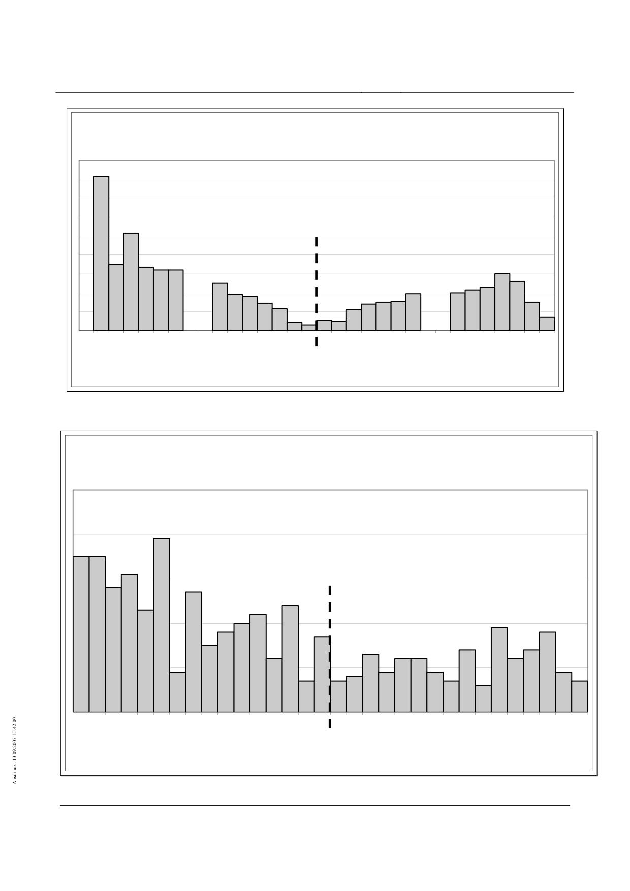
High-speed maglev systems
Maglev Technical Committee
Design principles
Guideway
Typical distribution of the guidance magnet forces from lateral wind along the length of
the vehicle
BM
BM
(1)
2
3
4
5
6
7
8
9
10 11 12 13 14 15 16
1
2
3
4
5
6
7
8
9
10 11 12 13 14 15 16
End section
Middle section
Partial magnet guidance FMTi
Figure 146 - Typical load arrangement for py,W with vW = 25 m/s and vFzg = 500 km/h
Typical distribution of the support magnet forces from lateral wind along the
length of the vehicle
(1)
2
3
4
5
6
7
8
9
10
11
12
13
14
15
16
1
2
3
4
5
6
7
8
9
10
11
12
13
14
15
16
End section
Middle section
Partial magnets support TMTi
Figure 147 - Typical load arrangement for pz,W with vW = 25 m/s and vFzg = 500 km/h
Title
High-speed Maglev Systems - Design principles
Guideway - Part II: Design
Doc. no.:
57288
Version
White Paper Issue date
15.02.2007
Page 94
High-speed maglev systems
Maglev Technical Committee
Design principles
Guideway
Title
High-speed Maglev Systems - Design principles
Guideway - Part II: Design
Doc. no.:
57288
Version
White Paper Issue date
15.02.2007
Page 95
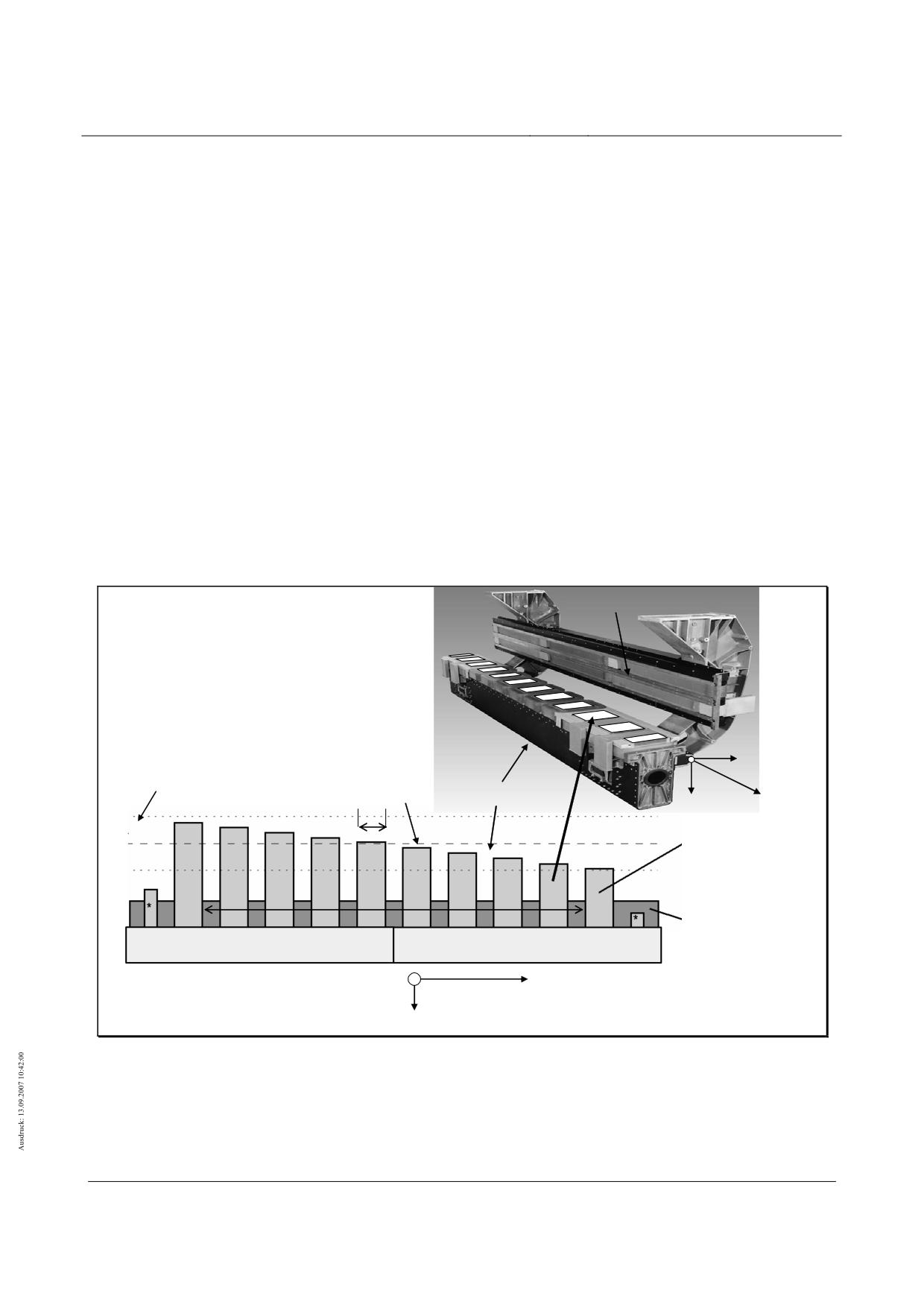
High-speed maglev systems
Maglev Technical Committee
Design principles
Guideway
Local load arrangements
Support magnet/long stator interface (stator pack)
Actions from frequent design situations (Q1...Q10)
For frequently variable design situations, calculate the local interface forces from the vehicle taking into ac-
count the relevant position of the potential vehicle-side combination groups and those resulting from
global actions.
For local verification, the control dynamic factor must also be taken into account for the structural dynamics
(see chapter 0). The minimum unit length is 1.548 m (partial magnet length). The maximum actions
must be increased or reduced for 2 adjacent partial magnets, taking the total loading into account.
In the case of simultaneous transfer of forces along the long stator in the x-direction with max. thrust, an
additional force redistribution of max. of 30% (see Figure 148) from the inclination of the support mag-
nets must be taken into consideration. In the case of lower thrust, this redistribution must be linearly
reduced according to the existing thrust force.
The action geometry (see Figure 148) must be superimposed as most unfavourable with the actions on the
lateral guidance rails/guidance magnet interfaces.
The load arrangement can also be used for global verification, i.e. the total of the forces remains the same.
The following figures show a control support magnet. The first and last magnets on a vehicle (nose and tail
magnets) may have two additional poles (see also Figure 122).
Information for determining the pole forces incl. 30 % redistribution: See annex chapter 0;
Guidance magnet
Condition:
Σ(pz/x,PK ⋅ LPK) = Σ pz/x,i ⋅ LTM
* End pole EP bears 50% of the
load from the main pole MP
Redistribution as result of
y
pitching moment at px
≠0
pz/x,PK
Support magnet
x
z
LPK
+ 30 %
Support
-
30 %
magnet
Pole forces
Total of global
MP
pz/x,PK
MP
actions
Σpz/x,i
TMTi
TMTi+1
EP
EP
y
x
z
Figure 148 - Typical load arrangement for the support magnet during operation without technical failure
Title
High-speed Maglev Systems - Design principles
Guideway - Part II: Design
Doc. no.:
57288
Version
White Paper Issue date
15.02.2007
Page 96
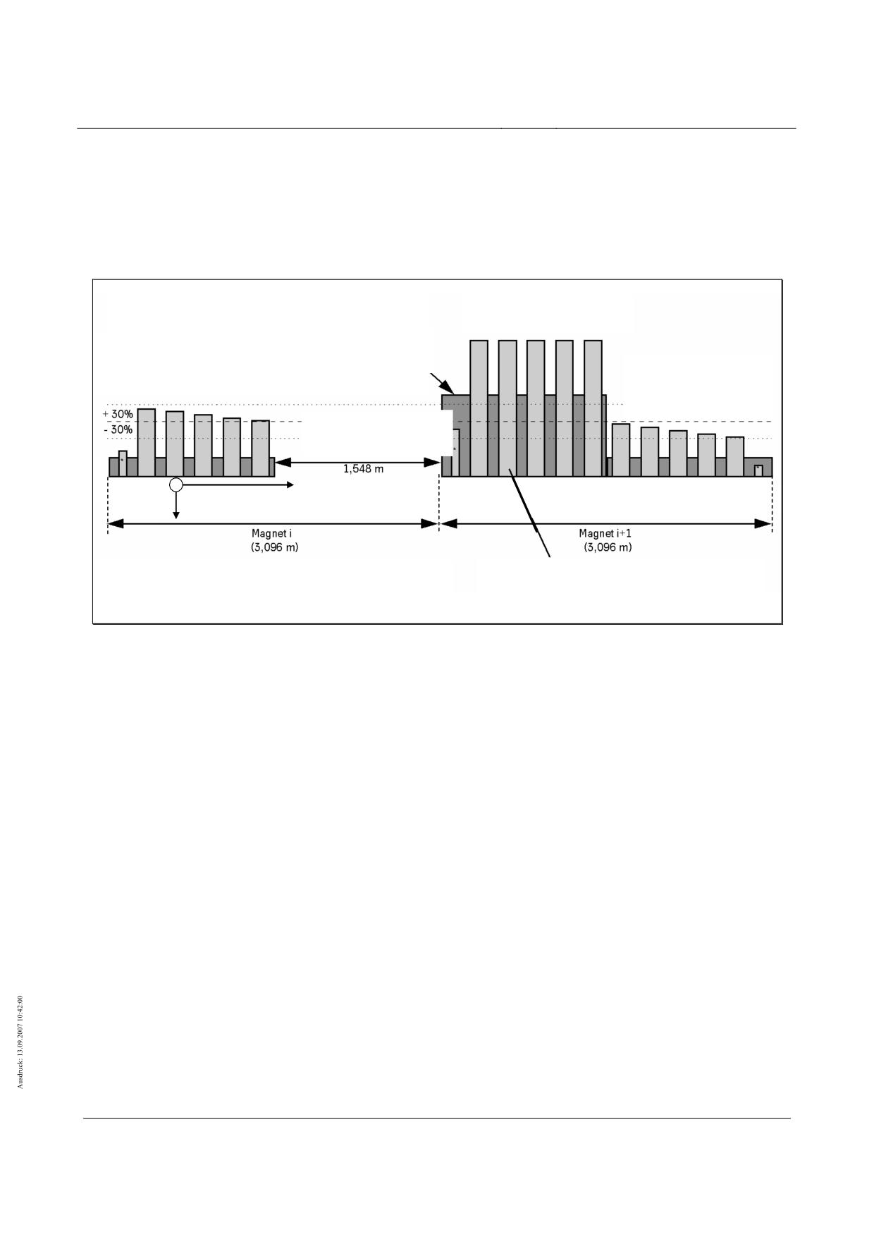
High-speed maglev systems
Maglev Technical Committee
Design principles
Guideway
Actions from infrequent design situations
Failure of a support magnet control system (Q11b)
The action geometry for the failure of a support magnet control system must be taken from Figure 149.
The corresponding action must be applied locally as a maximum value.
Partial magnet with
“additional” load TMTi+1
max pz,TMT,Q11b = 45 kN/m
Partial magnet
= 4 kN/m
max px,TMT,Q11b
without failure
Partial magnet
TMTi+2
without failure
TMTi+2
Malfunctioning
Partial magnet TMTi
y
x
z
•End pole EP bears 50% of the load from the main
Condition:
poles MP
Σ(pz/x,PK ⋅ LPK) = max pz,TMT,Q11b ⋅ LTM
Figure 149 - Typical load arrangement for the failure of a support magnet control system (Q11b)
Dual failure of support magnet control systems (Q11c)
The dual failure of the support magnet control systems on a levitation frame results in an action from the
levitation frame’s support skid (see 0).
Other infrequent design situations (Q11a, Q11d to Q11i)
The design situations Q11a, Q11d to Q11i must be handled according to Figure 148.
Local component dynamic
See chapter 0.
Title
High-speed Maglev Systems - Design principles
Guideway - Part II: Design
Doc. no.:
57288
Version
White Paper Issue date
15.02.2007
Page 97
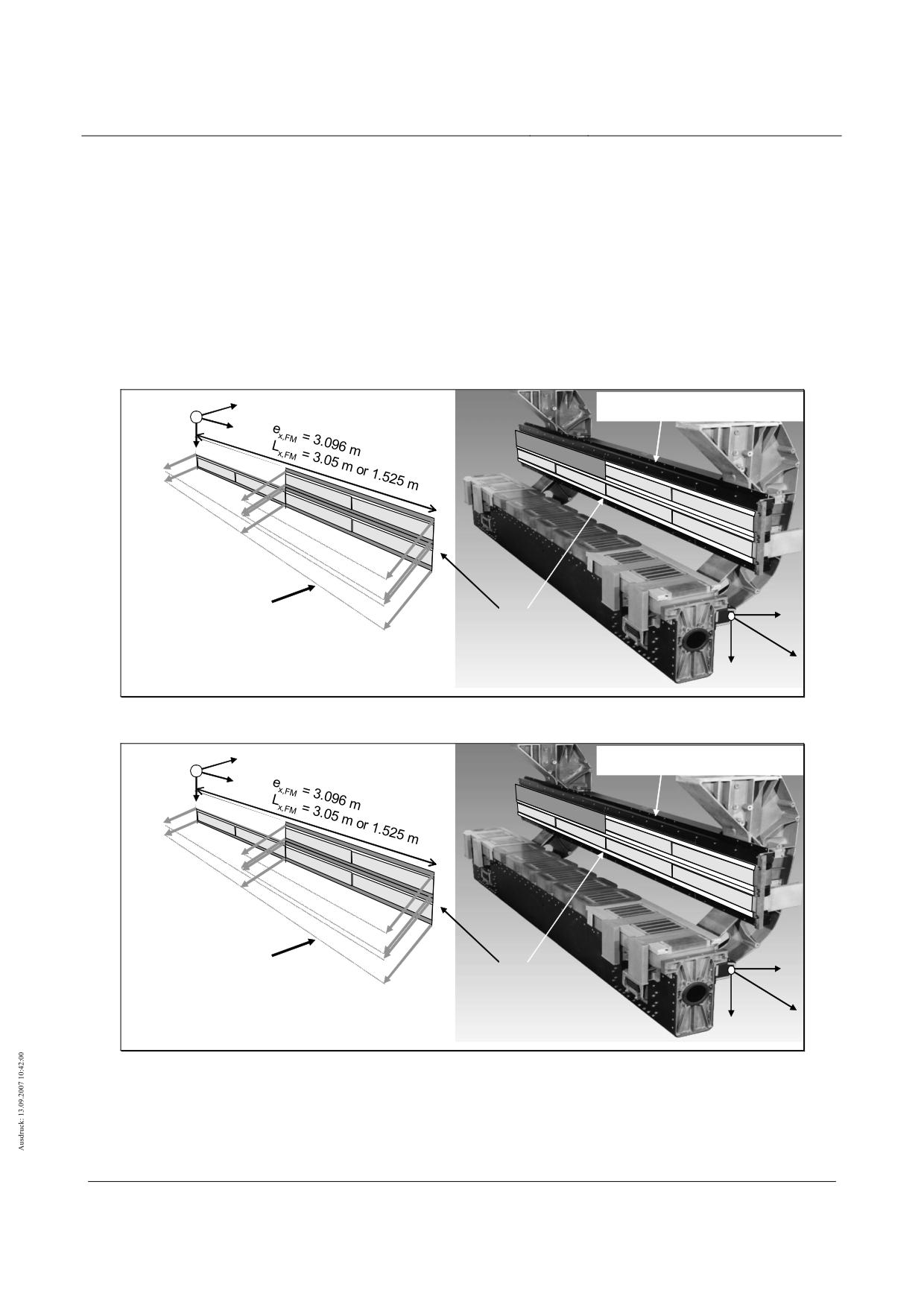
High-speed maglev systems
Maglev Technical Committee
Design principles
Guideway
Guidance magnets - lateral guidance rails interface
Actions from frequent design situations (Q1...Q10)
For frequently variable design situations, calculate the local interface forces from the vehicle taking into con-
sideration the relevant position of the potential vehicle-side combination groups and those resulting
from global actions. Make sure that the guidance forces can only be transferred by magnetic force.
For local verification, the control dynamic factor must also be taken into account for the structural dynamics
(see chapter 0). the actions must be increased or reduced for a max. of 2 adjacent partial magnets,
taking the total loading into account.
The action geometry (see chapter 0) must be superimposed as most unfavourable with the actions on the
long stator/support magnet interface.
y
Guidance magnet (corner m
x
z
Guidance magnet
y
Pole strip forces py,PL
4 guidance
magnet pole strips
Condition:
z
x
Σ(p
⋅ LPL) = Σ py,i ⋅ ex,FM
y,PL
Figure 150 - Typical load arrangement of a guidance magnet (corner magnet)c
y
Guidance magnet (corner m
x
z
Guidance magnet
y
Pole strip forces py,PL
4 guidance
magnet pole strips
Condition:
z
x
Σ(p
⋅ LPL) = Σ py,i ⋅ ex,FM
y,PL
Figure 151 - Typical load arrangement of a guidance magnet (middle magnet)
Title
High-speed Maglev Systems - Design principles
Guideway - Part II: Design
Doc. no.:
57288
Version
White Paper Issue date
15.02.2007
Page 98
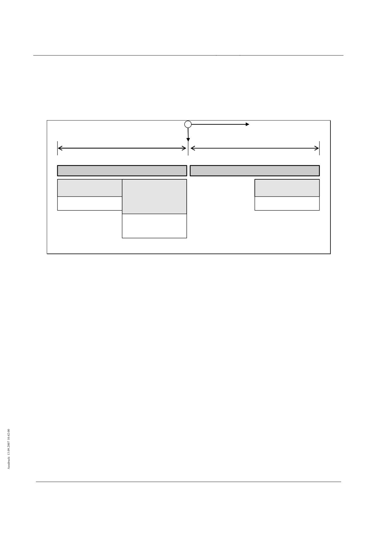
High-speed maglev systems
Maglev Technical Committee
Design principles
Guideway
Actions from infrequent design situations
Failure of a guidance magnet control system (Q11d)
The action geometry for the failure of a guidance magnet control system (MREF) must be taken from Figure
152.
z
x
y
LFM= 3.096m
LFM = 3.096 m
LFM,PL = 3.05 m
LFM,PL= 3.05m
GMi
GMi+1
Partial magnet
Partial magnet
Malfunctioning
Partial magnet
without failure
without failure
partial magnet
with “additional”
FMpy,PL
FMTi+1
py,PL
load
Fpy,PL, Q11d
Condition:
Σ(py,PL ⋅ LFMT,PL) = Σ py,i ⋅ LFMT,PL
LFMT,PL, Q11d = 3.05 m / 2
Max py,FMT, Q11d = 32 kN/m
Figure 152 - Typical load arrangement for the failure of a guidance magnet control system (Q11d)
Title
High-speed Maglev Systems - Design principles
Guideway - Part II: Design
Doc. no.:
57288
Version
White Paper Issue date
15.02.2007
Page 99
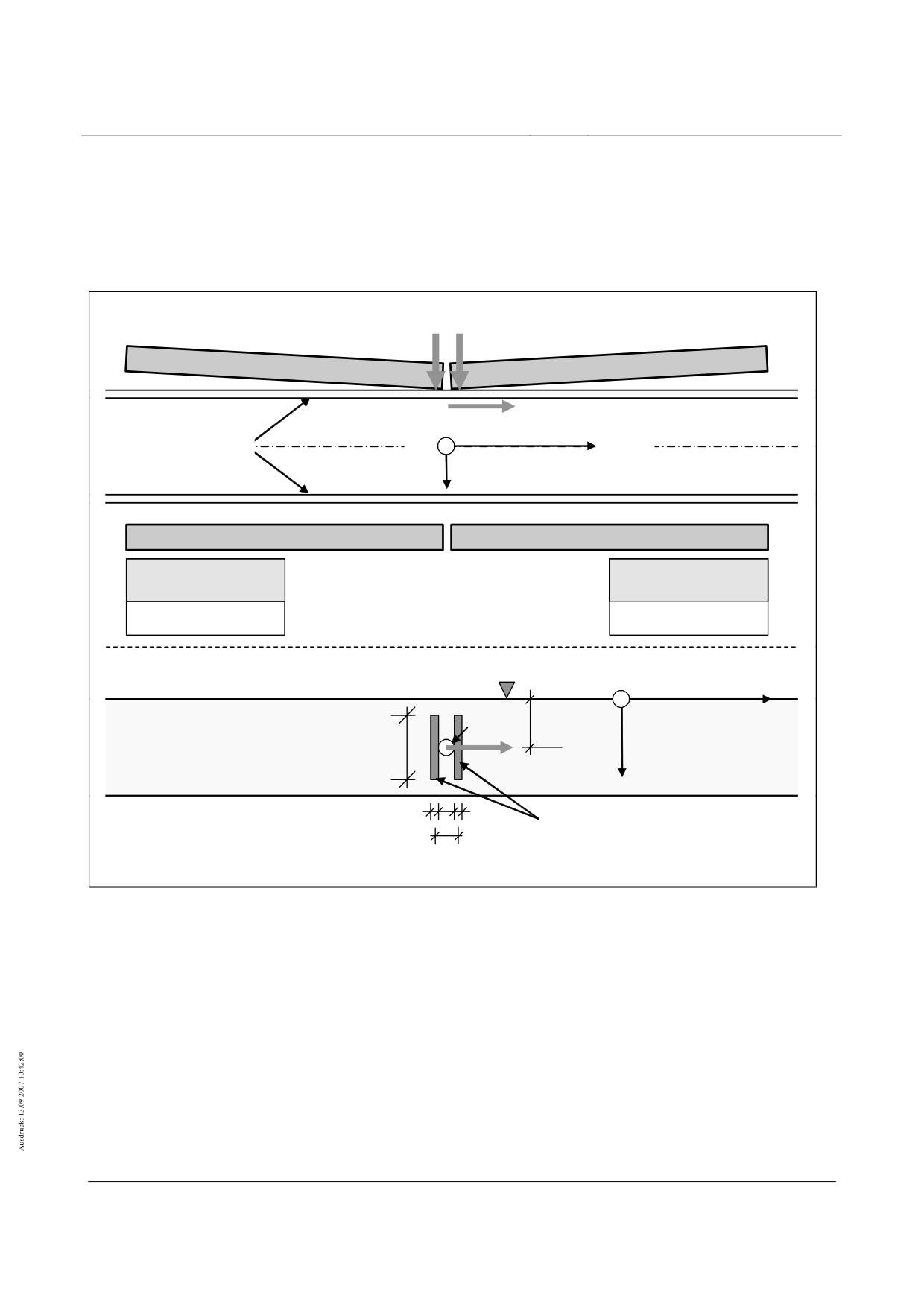
High-speed maglev systems
Maglev Technical Committee
Design principles
Guideway
Dual failure of guidance magnet control systems (Q11e)
The failure of two adjacent guidance magnet control systems results in an action from the guidance magnets
positioned opposite (activation of guidance magnets).
The action geometry for this local action must be taken from Figure 153.
Forces from the activation of the guidance magnets opposite (activation strips)
Lateral guidance rails
z
x, v
y
Guidance magnet i
Guidance magnet i+1
Partial magnet without
Malfunctioning partial
Partial magnet without
Malfunctioning partial
failure
magnet
failure
magnet
py,PL,
py,PL
Sliding strips level
Fy,FM
170 mm
y
x, v
z
Lateral guidance rail
283 mm
Fx,FM
5 mm
5 mm
Running surface of the guidance magnet
activation strips
Centre distance
approx. 41 mm
Figure 153 - Typical load arrangement in the event of dual failure of the guidance magnet control systems (Q11e)
Local component dynamic
For the actions as a result of the dual failure of guidance magnet control systems (activation of the guidance
magnets) according to chapter 0 an additional dynamic scaling factor to account for a local, design-
dependent component dynamic must not be applied, as the maximum dynamic loads of a potential
dynamic are already taken into account.
Title
High-speed Maglev Systems - Design principles
Guideway - Part II: Design
Doc. no.:
57288
Version
White Paper Issue date
15.02.2007
Page 100
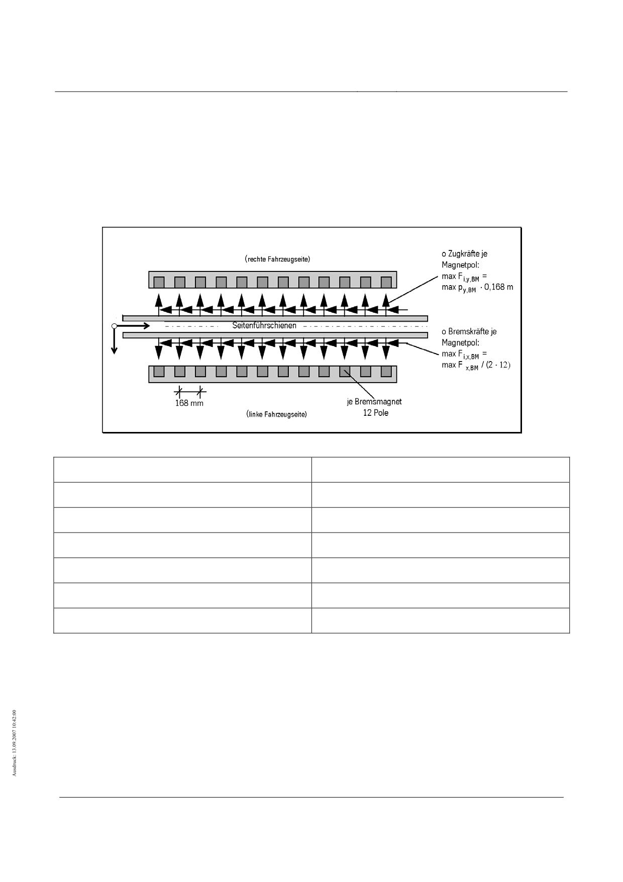
High-speed maglev systems
Maglev Technical Committee
Design principles
Guideway
Braking magnet/lateral guidance rails interface
Infrequent design situations (Q11f)
The action geometry for the actions from the non-contact or adjoining braking magnets must be taken from
Figure 154.
The braking magnet actions must be superimposed as infrequent variable actions, with the corresponding
actions from the support/guidance systems taking into account the conditions in 0 and 0 (see also
(8)).
z
x
y
Figure 154 - Typical load arrangement for the braking magnets (non-contact or adjacent)
Rechte Fahrzeugseite
Right-hand side of the vehicle
Seitenführschienen
Lateral guidance rails
Zugkräfte je Magnetpol
Tensile force for each magnet pole
Bremskräfte je Magnetpol
Braking force for each magnet pole
Je Bremsmagnet 12 Pole
12 poles per braking magnet
Linke Fahrzeugseite
Left-hand side of the vehicle
Abgesetzte Tragkufe
Set down support skid
Local component dynamic
See chapter 0.
Title
High-speed Maglev Systems - Design principles
Guideway - Part II: Design
Doc. no.:
57288
Version
White Paper Issue date
15.02.2007
Page 101
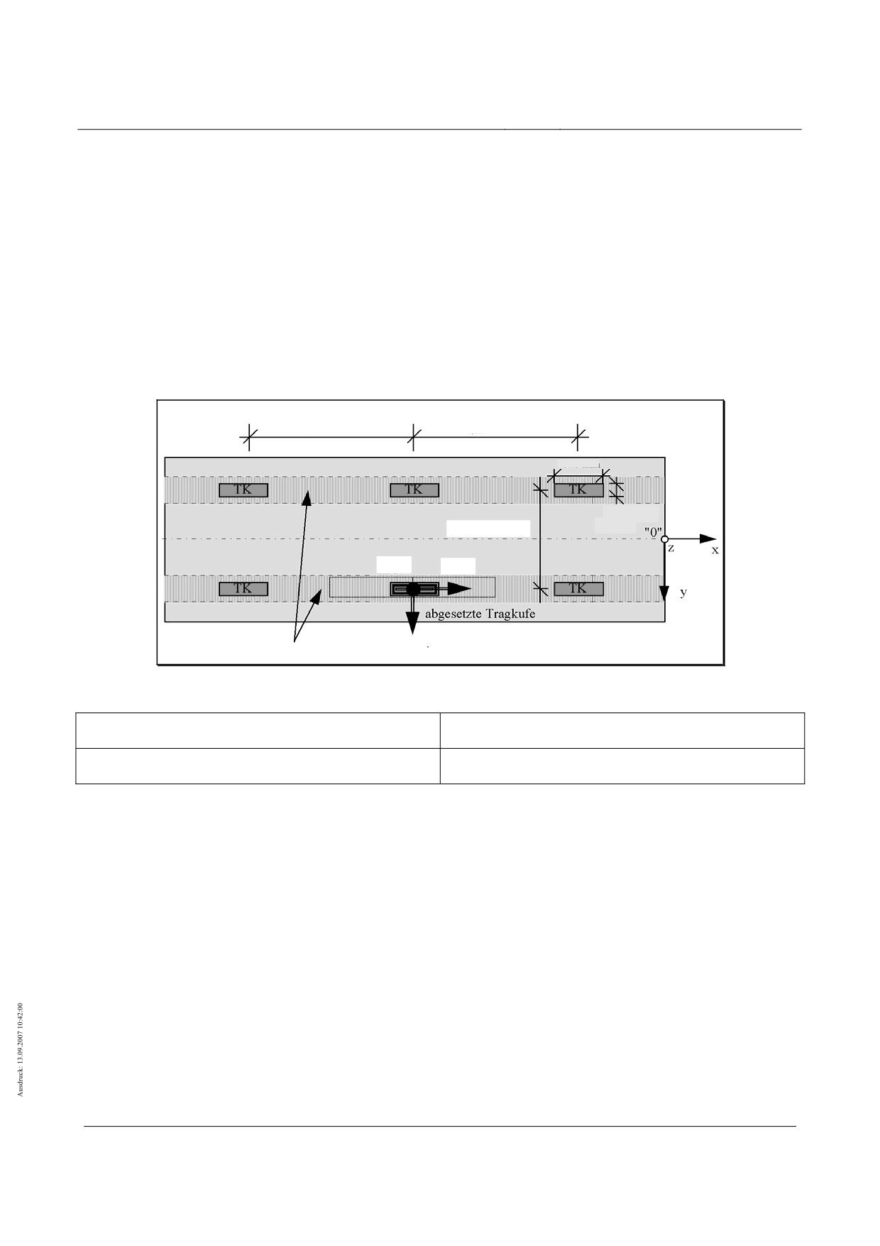
High-speed maglev systems
Maglev Technical Committee
Design principles
Guideway
Support skid/gliding strip interface
Actions from frequent design situations (Q1...Q10)
The support skids’ load arrangement as a result of actions in frequent design situations (stationary vehicle
being set down or stationary set down vehicle) must be taken from Figure 155 (see also chapter 0).
All actions from the vehicle are transferred to the guideway via the support skids.
Actions from infrequent design situations
Dual failure of support magnet control systems (Q11c)
Apply the max. impact force given in chapter 0 as the action from the support skid. Assume that the 2 partial
support magnets (TMTi and TMTi+1) directly assigned to the support skid, are inactive.
ex,TK = 3096 mm
ex,TK = 3096 mm
740 mm
110 mm
ey,TK = 2220 mm
Fz,TK
Fx,TK
TMTi
TMT
i+1
Fy,TK
Gleitleisten
Figure 155 - Typical load arrangement of support skids
Gleitleisten
Sliding srtip
abgesetzte Tragkufe
Set down support skid
Use of the vehicle "safe brake" (Q11f)
For the design situation "vehicle being set down" "safe brake" apply the load arrangements shown in Figure
155 and Figure 143.
One-sided set down of the vehicle (Q11i)
For the design situation "one-sided set down of the vehicle", the skids arranged on one side of the vehicle
bear the load (see also Figure 144).
Title
High-speed Maglev Systems - Design principles
Guideway - Part II: Design
Doc. no.:
57288
Version
White Paper Issue date
15.02.2007
Page 102
High-speed maglev systems
Maglev Technical Committee
Design principles
Guideway
Local component dynamic
An additional dynamic scaling factor to take into account a local design-dependent component dynamic does
not need to be applied for the infrequent design situation "dual failure of support magnet control sys-
tems", as the max. dynamic loads from the support skid are already taken into account.
Other interfaces
Action and load arrangement guidelines for other vehicle/guideway interfaces (e.g. external on-board energy
supply) must be determined individually for each project. These guidelines must be approved for use
by the responsible inspectorate.
Title
High-speed Maglev Systems - Design principles
Guideway - Part II: Design
Doc. no.:
57288
Version
White Paper Issue date
15.02.2007
Page 103
High-speed maglev systems
Maglev Technical Committee
Design principles
Guideway
Verification
General
Verification requirements are defined in detail, for example, in /EN 1990/ and DIN 1055 Part 100.
As a rule, the following must be verified:
Verification of the ultimate limit states
• Verification of the capacity of the components, cross sections and joints to withstand stress (tension
verification)
• Verification of the stability of the supporting structure
• Verification of stability
• Verification of material fatigue (verification of the service strength by cumulative damage or verifica-
tion of damage-equivalent stress variation range)
Verification for serviceability limit states
• Verification of deformation limit values specific to the high-speed Maglev system
• Verification of dynamic effects
• Verification of limit values specific to the building material
If the rules regarding applicability to the high-speed Maglev system guideway are not clear, then they must
be determined in agreement with the responsible inspectorate.
To carry out the verification specified above, on the basis of the actions put together in this design principles
document taking into account project-specific information on the significant operating and geometric
parameters for the sections to be verified, it is recommended that action tables are created (in simpli-
fied form if necessary). These tables can be created according to the verification process to individual-
ly assemble the significant combinations of actions. They must be approved by the responsible in-
spectorate as part of the verification audit.
The safety and serviceability of the guideway must be preserved during the planned (project-specific) period
of use by specific maintenance measures that are appropriate for the guideway construction.
The following general observations regarding actions must be considered during verification:
• The inertia forces must be calculated by taking into consideration the permissible accelerations
and velocities (min vFzg, max vFzg).
• The dead weight of the vehicle given in chapter 0 for the middle and end sections takes into ac-
count goods and passenger vehicles.
• Allow for dynamic step-ups of the actions. Dynamic factors and dynamic lateral forces do not need
to be applied when vFzg = 0 km/h. However, the control dynamic must always be considered.
• Actions resulting from interdependent causes must be applied together.
• Within the braking profile provided for the vehicle-side "safe brake" the actions must be classed as
infrequent. With regard to the braking process, setting down at vFzg ≤ 5 km/h must be only consid-
ered an infrequent event in defined sections (restricted area at and in front of the stopping place).
• Setting down at vFzg > 5 km/h with skidding of the set down vehicle on any area of the guideway
must be considered an accidental design situation (Worst-Case-Halt).
• Actions arising from maintenance must be considered and verified if necessary (see also /MSB
AG-FW ÜBG/). If necessary, potential actions arising from guideway maintenance must be
classed as variable or accidental actions according to the probability of them occurring.
• For the verification of shared guideway substructures for double track guideways, a shadow factor
may be applied for cross wind actions on the 2nd track (see EN 1991-1-4).
Title
High-speed Maglev Systems - Design principles
Guideway - Part II: Design
Doc. no.:
57288
Version
White Paper Issue date
15.02.2007
Page 104
High-speed maglev systems
Maglev Technical Committee
Design principles
Guideway
In agreement with the responsible inspectorate the safety factors can be adjusted to account for the low pro-
bability of occurrence of infrequent operating situations. Depending on the probability of occurrence
and the expected results, an inspection of the guideway is not necessarily required.
Simplification of the actions and/or load arrangements is permissible if it is clear or proven that the simplifica-
tions are on the safe side.
Title
High-speed Maglev Systems - Design principles
Guideway - Part II: Design
Doc. no.:
57288
Version
White Paper Issue date
15.02.2007
Page 105
High-speed maglev systems
Maglev Technical Committee
Design principles
Guideway
Verification of the ultimate limit states
General
Verification must be carried out for the actions resulting from the line routeing and operating parameters (e.g.
for straight guideway beams ay = 0) within the limits laid down by the MbBO and with the limits provi-
ded for the vehicle weight, accelerations and other actions.
To verify the ultimate limit states, the design parameters for the decisive loading cases/design situations
must be determined from the actions by a combination of the simultaneously occurring actions.
The combination rules can be found in /EN 1990/ chapter 6.4.3. If it is not clear which is the leading action,
consider each variable action in turn as the leading variable action. Combinations for designing acci-
dental situations are based either on an explicit accidental action or applied to the situation (condition)
according to an accidental event.
Combinations may be simplified. However, it must be verified that simplified combinations are on the safe
side in comparison to the standard combinations.
Partial safety factors of the actions
The partial safety factors of the actions for the verification of the ultimate limit states must be taken from
Table 113.
When forming the loading cases or combinations, apply the representative and characteristic values of the
actions in accordance with the Eurocodes and the notes for Table 113 with the appropriate partial sa-
fety factors.
The partial safety factors of the actions cover, in accordance with DIN 1055 part 100,
• The possibility of unfavourable deviations of the actions (magnitude and distribution of the actions),
• The possibility of inaccurate model assumptions for the actions and
• Uncertainty in the determination of the effects.
The partial safety factors are assigned to the following actions:
• Permanent actions
⇒
γG
• Variable actions (frequent and infrequent)
⇒
γQ
• Accidental actions
⇒
γA
For the accidental actions (A), the safety margins given in Table 113 are permissible under acceptance of
sectional damage.
If the result is relatively low local action effects, then a check must be carried out to see whether small ad-
justments to the system or the geometry of the actions will result in larger action effects or vice versa.
If necessary, additional buffers for the action effects must be provided.
Title
High-speed Maglev Systems - Design principles
Guideway - Part II: Design
Doc. no.:
57288
Version
White Paper Issue date
15.02.2007
Page 106

High-speed maglev systems
Maglev Technical Committee
Design principles
Guideway
Effect
Symbol
Situations *
Partial safety factors γ
G/Q A
Permanent actions G1… G6:
See Eurocodes and DIN technical report
Variable actions from the vehicle
unfavourable
γQi
1.35
1
1)
Inertia forces from permissible and maximum
Q1...Q6
vehicle weight, constraint forces, lead dynamic
favourable
γ
1.0 / 0
0
Qi
unfavourable
γQi
1.35
1
1)
Q7...Q8
Aerodynamic actions from vVeh
favourable
γQi
0
0
unfavourable
γQi
1.5
1
1)
Q9
Aerodynamic actions from wind on the vehicle
favourable
γQi
0
0
unfavourable
γQi
1.35
1
1)
Q10
Temperature as a result of propulsion system
favourable
γQi
0
0
unfavourable
γQi
1.35
0
2)
Actions resulting from technical failure or
Q11
malfunction
favourable
γ
0
0
Qi
Other variable actions
unfavourable
γQi
1.5
1
2)
Q30
Actions resulting from maintenance
favourable
γQi
0
0
unfavourable
γQi
1.5
1
3)
o general
favourable
γQi
0
0
Q50 ... Q60
unfavourable
γQi
1.35
1
o with verified limit values
favourable
γQi
0
0
Accidental actions
A1...A9
General
γAi
1
4)
* G/Q: Permanent and variable situations; A: Accidental situations
Table continues overleaf.
Table 91 - Partial safety factors of the actions
Title
High-speed Maglev Systems - Design principles
Guideway - Part II: Design
Doc. no.:
57288
Version
White Paper Issue date
15.02.2007
Page 107
High-speed maglev systems
Maglev Technical Committee
Design principles
Guideway
Table cont.: Partial safety factors of the actions
Notes
1) Taking limit values from actions resulting from the vehicle into consideration (e.g. vehicle dead weight,
payloads, permissible accelerations), which have been determined in accordance with current regula-
tions, a partial safety value of γQi = 1.35 can be applied on agreement with the responsible inspectorate .
The classification of the possible vehicle weight conditions according to Table 100 must also be observed.
2) The vehicle-side actions resulting from technical failure or malfunction relating to individual guideway
elements (e.g. guideway beams) are rare or very rare events. Due to their low probability of occurrence
they should be regarded as predominantly static actions. Superimposing several such actions in accor-
dance with Table 93 is not required. In agreement with the responsible inspectorate the partial safety fac-
tor can be reduced, if necessary, to account for the low probability of them occurring.
There is no need to superimpose the vehicle-side actions from infrequent design situations Q11 (a...k)
with accidental actions A1...A9 due to their low probability of occurrence.
3) If the environmental thermal actions are determined by secure measurements, a lower value, which must
be determined in agreement with the responsible inspectorate (e.g. γQ50 = 1.35 ), may be used instead
of γQ50 = 1.50. When superimposing the snow/ice loads given in 0 (limit value taking into account the
space between the vehicle and guideway) with traffic loads, a value of γQ50 = 1.00 may be used.
4) Whether it is necessary to form accidental design situations taking into account actions from mainte-
nance must be checked from case to case and agreed upon with the responsible inspectorate.
Title
High-speed Maglev Systems - Design principles
Guideway - Part II: Design
Doc. no.:
57288
Version
White Paper Issue date
15.02.2007
Page 108

High-speed maglev systems
Maglev Technical Committee
Design principles
Guideway
Combination values
When forming combinations of actions according to the combination rules provided in /EN 1990/, the combi-
nation factors ψ compiled in the following tables must be used to take into account the simultaneity
and probability of occurrence of the actions, whilst observing the accompanying notes.
The combination factors of the variable actions are arranged into the following groups based on the probabi-
lity of occurrence of the actions:
• For variable actions
⇒
ψ0
• For infrequent actions (1/year) ⇒
ψ1'
• For frequent actions (1/week)
⇒
ψ1
• For quasi-permanent actions
⇒
ψ2
Combination factors ψ
ψ0
ψ1'
ψ1
ψ2
Notes
Actions resulting from the vehicle
Q1/Q2
Dynamic inertia forces from the vehicle weight
1
1
1
1
Q3/Q4
Uneven distribution of the payload
1
1
1
0
Q5
Lead dynamic (dyn. lateral forces)
1
1
1
1
Q6
Constraint forces in tight radii
1
1
1
1
Q7
Aerodynamic lateral forces
1
1
1
0
Q8
Airstream actions
1
1
1
1
Q9
Wind actions on the vehicle
0.6
0.6
0.5
0
4)
Q10
Temperature as a result of propulsion system
1
1
1
1
Actions resulting from technical failure or malfunc-
Q11a..k
1
0
0
0
5) 6)
tion
Q11l
Increase in vehicle weight due to snow
0.7
0.2
0.2
0
Other variable actions
Q30
Actions from maintenance
1)
Q50
Environment temperature
0.6
0.8
0.6
0.5
4) 5) 7) 8)
Q51
Wind on the supporting structure
0.6
0.6
0.5
0
4)
Q52
Snow and ice loads
0.7
0.2
0.2
0
Q53
Variable water pressure forces
2)
Q54
Wind load on construction stages
2)
Q55
Maintenance conditions
2)
Q56
Construction stages
2)
Q57
Actions from track switching equipment
1.0
1.0
1.0
1.0
Q58
Displacement resistance of bearings
2)
Q59
Failure of supporting structure elements
2) 3)
Q60
Lateral earth pressure from variable actions
2)
Table continues overleaf.
Table 92 - Combination factors ψi of actions
Title
High-speed Maglev Systems - Design principles
Guideway - Part II: Design
Doc. no.:
57288
Version
White Paper Issue date
15.02.2007
Page 109
High-speed maglev systems
Maglev Technical Committee
Design principles
Guideway
Table cont.: Combination factors ψi of actions
Notes
1) The combination factors for actions resulting from maintenance must be determined individually and
agreed upon with the responsible inspectorate.
2) The combination factors for the respective actions can either be taken from /EN 1990/ or the appropriate
rules, standards and regulations or determined on a individual basis in agreement with the responsible
inspectorate.
3) The loss of, for example, a screw connection or other component must be considered a permanent ac-
tion if it cannot be guaranteed that it will be repaired immediately.
4) When using Q9 and Q51 as the leading variable action, a combination factor of ψ0 = 0.5 can be set for
Q50b+c, and vice versa.
5) When thermal actions resulting from braking magnet BM, support skids SS and mechanical guidance
elements MGE, are superimposed with environmental thermal actions, the environmental uneven heat-
ing (Q50c) between different components can be reduced to half the value.
6) Due to the low probability of occurrence, the combination factors ψ1 or ψ1 can be used with the remaining
actions in Q11a, Q11b, Q11c, Q11d, Q11e, Q11g, Q11i (case 1), Q11j , Q11k as leading variable actions
for forming the combinations of actions. The actions Q11a..k do not need to be applied simultaneously.
If the action Q11l must specifically be considered for a project, combine Q11l(1) as opposed to Q11l(2)
with the remaining Q11 actions.
7) Maximum temperature differences between the upper and bottom chord of the beam and maximum
temperature difference between the left and right sides of the beam must not be considered simultane-
ously with their maximum values. When superimposing temperature differences, one of the two tem-
perature differences should be reduced by 1/3.
8) When superimposing the beam temperature difference in accordance with chapter 0 with actions as a
result of traffic, apply the appropriate value for ∆T in accordance with Table 110.
9) For the verification of the serviceability limit state do not apply the actions from Q11a .. Q11k.
Title
High-speed Maglev Systems - Design principles
Guideway - Part II: Design
Doc. no.:
57288
Version
White Paper Issue date
15.02.2007
Page 110
High-speed maglev systems
Maglev Technical Committee
Design principles
Guideway
Proof of the performance capability limit states
General
(1)
The limit values relating to guideway deformation and the regulations concerning the furnishing of
proof which are specific to high-speed maglev systems are indicated below. These reflect current ex-
perience levels and, when observed, generally result in guideways which are fit for their purpose, i.e.
guideways which are in keeping with the system.
(2)
Permitted deformations, offsets, displacements and gap changes are defined as follows in relation to
the functional areas comprising stator level, lateral guide rail level and slider level, as well as in rela-
tion to the position of the space curve in the three directions according to the local coordinate system:
• permitted long- or short-wave deformations in the support structures (e.g. global girder deflection)
which are the result of actions
• permitted displacements in the functional areas at the girder joint and in the girder section which
are the result of actions
• permitted elastic and plastic deformations in the guideway substructures (long-wave alteration in
the position of the functional areas)
(3)
In addition to the static deformations resulting from the actions of vehicles, the dynamic behaviour
(vibrational behaviour) influences the performance capability of the guideway. Specifications in this re-
gard are given in Chapter 10.3.5.
(4)
The combinations of effects regarding the performance capability limit states are generally laid down
by means of the equations defined in EN 1990.
(5)
The general combination factors shall be taken from Table 114.
(6)
In addition, the load model, effects and combinations of effects which are specific to high-speed
maglev systems shall be taken into consideration in accordance with the following sections.
(7)
The effects arising from Q11a to Q11k shall not be specified.
(8)
In addition to these requirements which are specific to high-speed maglev systems, the corresponding
provisions adopted by the building inspectorate concerning proof of performance capability shall be
taken into consideration (e.g. the limiting of compressive strains and crack widths in the concrete con-
struction).
(9)
If the following chapters or Annex (Chapter 11.4) do not stipulate any applicable requirements in rela-
tion to limit values and combinations of effects which are specific to high-speed maglev systems as
proof of performance capability, proof of the vehicle’s compatibility must be furnished in relation to the
accepted limit values and combinations.
(10)
In each individual case, proof of the vehicle’s compatibility must be furnished as proof of the perform-
ance capability of construction methods and structural forms not qualified previously.
Global deformations in discretely mounted guideway super-
structures
General
(1)
As regards the deformation limit values below, a maximum free lateral acceleration of ay = ± 1.5 m/s²
is taken as a basis.
(2)
In the case of discretely mounted support structures, proof of global deformations in functional areas
may generally be furnished in the form of proof of the centre of gravity displacement of the support
structures, provided functional area deformation is negligibly small compared with the amount of de-
formation in the support structure.
Title
High-speed Maglev Systems - Design principles
Guideway - Part II: Design
Doc. no.:
57288
Version
White Paper Issue date
15.02.2007
Page 111
High-speed maglev systems
Maglev Technical Committee
Design principles
Guideway
(3)
As regards the static proofs of deflections in the y and z directions given below, maximum dynamic
cambers of 20% in the z direction and 40% in the y direction form the basis for permitted deflections. If
dynamic tests establish greater dynamic cambers, static deflections must be reduced to the extent that
the permitted deformations specified below are not exceeded, taking into account the existing dynamic
camber.
(4)
Proof must be furnished in a particular case as to the extent to which static deflection may be in-
creased in the case of smaller dynamic cambers.
Deformations in the z direction
Effects resulting from the vehicle
General
(1)
Proof of permitted deflection in the z direction must be furnished for all routing scenarios, girder con-
structions and static systems under the following girder loads (see Chapter 8.2.1.2):
pz,fz = pz,ZG = 29 kN/m
(2)
As regards the static systems indicated below, consideration must be given to the following limit val-
ues as regards deformation in the z direction. Generally speaking, the span of the support structures
LSt shall be used as the reference length when furnishing proof of the global deformations in guideway
superstructures. Depending on the support structure mounting conditions, LSt may differ for the y and z
directions.
(3)
The permitted deformations indicated correspond to a tangential torsion at the end of the girder of ϑy =
0.0008 rad.
(4)
Permitted girder deformation progression (e.g. maximum deflection) in the case of girders with sudden
changes in rigidity shall be specified in a particular case.
(5)
When determining the load-free design precurvature of the support structures in the z direction in ac-
cordance with the Guideway design principles for high-speed maglev systems - Part III: Geometry, the
actual maximum deflection under the effect of the mean vehicle weight pz,MG = 26 kN/m shall be
specified as the load for all girder sections.
Simple beam N = 1
(1)
Maximum permitted deflection in the midspan of the simple beam:
( 28)
max fz,Fzg ≤ LSt / 4000
Title
High-speed Maglev Systems - Design principles
Guideway - Part II: Design
Doc. no.:
57288
Version
White Paper Issue date
15.02.2007
Page 112
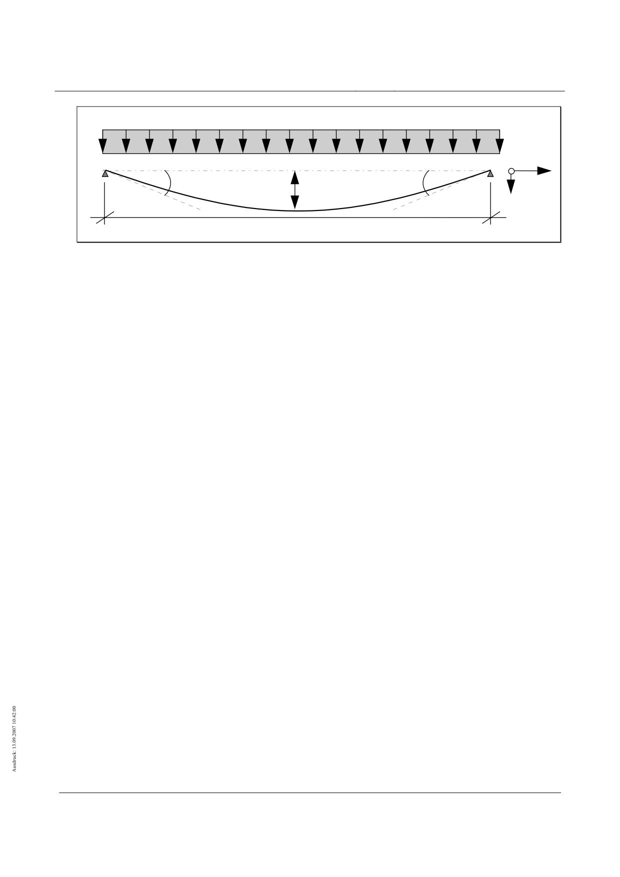
High-speed maglev systems
Maglev Technical Committee
Design principles
Guideway
pz,fz
y
x
max fz,Fzg
z
LSt
Fig. 156 - Permitted deformation in the z direction caused by a vehicle in the case of simple beams
Title
High-speed Maglev Systems - Design principles
Guideway - Part II: Design
Doc. no.:
57288
Version
White Paper Issue date
15.02.2007
Page 113
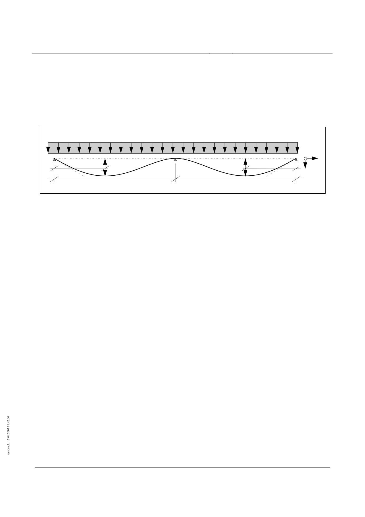
High-speed maglev systems
Maglev Technical Committee
Design principles
Guideway
Two-span beams with the same spans N = 2
(1)
Maximum permitted deflection in the girder section where xmax fz = 0.421⋅ LSt, in which connection, both
girder sections are subjected to loads:
( 29)
max fz,Fzg ≤ LSt / 4800
pz,fz
y
max fz,Fzg,1
max fz,Fzg,2
x
xmax fz,1
xmax fz,2
z
LSt,1
LSt,2
Fig. 157 - Deflection in the z direction in the case of two-span beams with the same spans
Two-span beams with unequal spans
(1)
The cross-sectional values for the girder sections shall be chosen such that, when both sections are
subjected to loads, the requirements pertaining to two-span beams with the same spans (see Chapter
10.3.2.2.1.3) are observed in relation to each section.
Multiple span girders N > 2
(1)
The cross-sectional values for girders with more than two sections shall be chosen such that when all
the sections are subjected to loads, the following requirements are observed:
• Edge sections: limit value the same as with two-span beams
• Internal sections: limit value the same as with simple beams
Title
High-speed Maglev Systems - Design principles
Guideway - Part II: Design
Doc. no.:
57288
Version
White Paper Issue date
15.02.2007
Page 114
High-speed maglev systems
Maglev Technical Committee
Design principles
Guideway
Temperate differential
(1)
Deformations resulting from differences in temperature between the top and bottom booms may not
exceed the following limit values (also refer in this regard to Chapter 8.2.3.3).
(2)
If a temperature differential ∆T0 is already taken into consideration when stipulating the load-free de-
sign precurvature (e.g. ∆T0 = 7 K, i.e. the theoretical position which is not subject to a load is adjusted
with a temperature differential of 7 K), this nominal temperature differential may be taken into account
accordingly when proving deformations as a result of a temperature differential as per Chapter
8.2.3.3.2.
Simple beam N = 1
( 30)
to > tu:
max fz,∆T = LSt / 6500
( 31)
to < tu:
max fz,∆T = + LSt / 5400
Two-span beams with the same spans N = 2
( 32)
to > tu:
max fz,∆T = LSt / 8000
( 33)
to < tu:
max fz,∆T = + LSt / 6500
Two-span beams with unequal spans
(1)
The cross-sectional values for the girder sections shall be chosen such that, when specifying ∆T in
both sections, the requirements pertaining to two-span beams with the same spans (see Chapter
10.3.2.2.2.2) are observed in relation to each section.
Multiple span girders N > 2
(1)
The cross-sectional values for girders with more than two sections shall be chosen such that when
specifying ∆T in all sections, the following requirements are observed:
• Edge sections: limit value the same as with two-span beams
• Internal sections: limit value the same as with simple beams
Deformations specific to the building material
(1)
Long-wave deviations from the support structure theoretical position as a result of properties which are
specific to the building materials (e.g. creeping/shrinkage of the concrete) shall be estimated for the
requisite period of use using approved calculation methods.
(2)
The calculated values shall be incorporated within the permitted tolerance band for long-wave devia-
tion which is laid down in the Guideway design principles for high-speed maglev systems - Part III:
Geometry.
Title
High-speed Maglev Systems - Design principles
Guideway - Part II: Design
Doc. no.:
57288
Version
White Paper Issue date
15.02.2007
Page 115
High-speed maglev systems
Maglev Technical Committee
Design principles
Guideway
Deformations in the y direction
Effects resulting from the vehicle
General
(1)
Proof of permitted deflection in the y direction must be furnished for all routing scenarios, girder con-
structions and static systems under the following girder loads:
p
= pz,ZG ⋅ max ay / g = 29 kN/m ⋅ 1.5 m/s² / 9.81 m/s² = 4.5 kN/m
y,fy
(2)
Permitted girder deformations relate to girders which have constant rigidity. As regards support struc-
tures with different girder rigidities (e.g. sudden changes in rigidity), the permitted deformation pro-
gression shall be specified in a particular case.
Simple beam N = 1
(1)
Maximum permitted deflection in the y direction as per fig. 156 in the midspan:
( 34)
max fy,Fzg ≤ ⏐ LSt / 15000 ⏐
Two-span beams with the same spans N = 2
(1)
Maximum permitted deflection in the y direction as per fig. 157 in the girder section where x = 0.421⋅
LSt:
( 35)
max fy,Fzg ≤ ⏐ LSt / 18000 ⏐
Two-span beams with unequal spans N = 2
(1)
The cross-sectional values for the girder sections shall be chosen such that, when both sections are
subjected to loads, the requirements pertaining to two-span beams with the same spans (see Chapter
10.3.2.3.1.3) are observed in relation to each section.
Multiple span girders N > 2
(1)
The cross-sectional values for girders with more than two sections shall be chosen such that when all
the sections are subjected to loads, the following requirements are observed:
• Edge sections: limit value the same as with two-span beams
• Internal sections: limit value the same as with simple beams
Temperate differential
General
(1)
Deformations resulting from differences in temperature between the left and right sides of the support
structure girder should not exceed the following limit values (also refer in this regard to Chapter
8.2.3.3).
Simple beam N = 1
( 36)
max fy,∆T = ± LSt / 5800
Two-span beams with the same spans N = 2
( 37)
max fy,∆T = ± LSt / 6960
Title
High-speed Maglev Systems - Design principles
Guideway - Part II: Design
Doc. no.:
57288
Version
White Paper Issue date
15.02.2007
Page 116
High-speed maglev systems
Maglev Technical Committee
Design principles
Guideway
Two-span beams with unequal spans N = 2
(1)
The cross-sectional values for the girder sections shall be chosen such that the requirements pertain-
ing to two-span beams with the same spans (see Chapter 10.3.2.3.2.3) are observed in relation to
each section.
Multiple span girders N > 2
(1)
The cross-sectional values for girders with more than two sections shall be chosen such that the fol-
lowing requirements are observed:
• Edge sections: limit value the same as with two-span beams
• Internal sections: limit value the same as with simple beams
Deformations specific to the building material
(1)
Long-wave deviations from the support structure theoretical position as a result of properties which are
specific to the building materials (e.g. creeping/shrinkage of the concrete) shall be estimated for the
requisite period of use using approved calculation methods.
(2)
The calculated values shall be incorporated within the permitted tolerance band for long-wave devia-
tion which is laid down in the Guideway design principles for high-speed maglev systems - Part III:
Geometry.
Wind
(1)
Additional support structure deformations as a result of wind are compatible with the system when
observing the requirements mentioned in Chapters 10.3.2.3.1 and 10.3.2.3.2 pertaining to rigidity and
maximum wind speeds (see Q9) in wind zone II up to a height of hG,Ground = 20 m (see Table 108), tak-
ing into account note 7 to Table 113. Proof of deformation as a result of wind is therefore not required.
(2)
With higher wind speeds, the data contained in Chapter 8.2.1.4.7 must be taken into account. System
compatibility shall be examined in this instance.
Deformations in the x direction
Traffic
(1)
The permitted gap changes between the support structures must be observed (see Chapter 10.3.7).
(2)
Gap changes in the x direction may also be caused, for instance, by support structure deformations in
the area of the x solid bearing (e.g. crosswise bending of support brackets or as a result of elastic de-
formation of the bearings themselves).
Temperature
(1)
The permitted gap changes between the support structures must be observed (see Chapter 10.3.7).
Creeping and shrinkage
(1)
The permitted gap changes between the support structures must be observed (see Chapter 10.3.7).
Wind
(1)
Support structure deformations in the x direction as a result of wind are not definitive.
Title
High-speed Maglev Systems - Design principles
Guideway - Part II: Design
Doc. no.:
57288
Version
White Paper Issue date
15.02.2007
Page 117
High-speed maglev systems
Maglev Technical Committee
Design principles
Guideway
Deformation as a result of torsion around the x axis
(1)
On account of the gap between the centre of gravity of the vehicle and the shear centre of the guide-
way in the y and z directions, torsion in the girder cross-section around the x-axis arises as a result of
effects in the y and z directions.
(2)
Torsion brings about displacement of the functional areas in the y and z directions. The level of dis-
placement in the y direction is negligible.
(3)
In simplified terms, displacement of the functional areas in the z direction as a result of torsion is lim-
ited by the following rules:
a) The calculated deformation fz,rot,x of the stator level in the z direction as a result of torsion may ex-
ceed the permitted deformation in the z direction due to vertical effects (see Chapter 10.3.2.2.1) at any
point by a maximum of 20% of the permitted deformation as per Chapter 10.3.2.2.1.
b) If the calculated, actual static deformation as a result of vertical effects is smaller than the limit value
as per Chapter 10.3.2.2.1, deformation as a result of torsion may be no more than 50% of the limit
value as per Chapter 10.3.2.2.1, in which connection the limit as per a) may not be exceeded.
c) The static line load stat py,fy = 4.5 kN/m as per Chapter 10.3.2.3.1 shall be specified as an action in
the vehicle’s centre of gravity.
Permitted local support structure deformations
(1)
Local guideway superstructure deformations should not result in the respective assemblies being posi-
tioned in areas where they are not allowed (contact freedom).
(2)
Limit values for the allowable positions of the lateral guide rails, sliding rails and the longitudinal stator
are laid down in the Principles concerning the overall system design of high-speed maglev systems
and the Guideway design principles for high-speed maglev systems - Part III: Geometry.
(3)
As regards the stator level, a maximum offset of 4 mm in the z direction between two stator plates is
permitted temporarily in a particular case (e.g. with an “activated” redundant attachment).
(4)
As regards support structures whose functional areas comprising the lateral guide rail level and slider
level are interrupted in a grid smaller than 6.192 m, the limit values specified below do not generally
apply to offsets. To this end, construction-dependent limit values shall be laid down, providing evi-
dence of the vehicle’s compatibility.
Permitted deformations in guideway plates
(1)
Given the small spans of guideway plates (approx. 6 m), as regards the guideway plates, the dis-
placement criteria between the individual plates are generally definitive (see Chapter 10.3.6).
(2)
Since guideway plates are generally repeatedly mounted in a statically indeterminate manner on con-
tinuous strip foundations, an overall deformation assessment of the plates / foundation system is nec-
essary in an individual case.
Dynamic deformations when stimulating inherent frequencies
(1)
As a result of vehicles stimulating the guideway itself, dynamic oscillation amplitudes may be gener-
ated in the functional levels which may result in minimal magnet disconnections (also refer to Chapter
7.4 in this regard).
(2)
Magnet disconnections are not anticipated when these oscillation amplitudes are limited to a maxi-
mum of ± 3 mm.
(3)
System compatibility must be verified in each case by means of tests.
Title
High-speed Maglev Systems - Design principles
Guideway - Part II: Design
Doc. no.:
57288
Version
White Paper Issue date
15.02.2007
Page 118
High-speed maglev systems
Maglev Technical Committee
Design principles
Guideway
Permitted offsets in the functional levels
Variable effects to be specified
(1)
Q1 ÷ Q60 (minus Q11) or the effects indicated in Chapters 10.3.6.2 and 10.3.6.3 where γi = 1.0, com-
bination factors ψi as per Table 114 and combinations of effects as per EN 1990.
(2)
The limit values below apply irrespective of the type and design of the guideway substructures, i.e.
also in the case of separate substructures along girder joints.
Permitted offsets in the stator and slider levels
(1)
as a result of a live load in the x direction (braking force) as per Chapter 8.2.1.2 (Q1+Q2) arising from
the elastic deformation of the guideway substructures:
permitted ∆Vz,1 = 0.4 mm
(2)
as a result of a live load as per Chapter 8.2.1.4 (Q1+Q2) arising from the elastic deformation of the
guideway superstructures, the guideway bearings and the guideway substructures:
permitted ∆Vz,2 = 0.6 mm
(3)
as a result of the plastic deformation of the guideway substructures:
permitted ∆Vz,3 = 0.5 mm
Permitted offsets in the lateral guide rail level
(1)
as a result of a live load in the y direction as per Chapter 8.2.1.2 (Q1+Q2) arising from elastic beam
bending and as a result of the elastic and plastic deformation of the substructures (subsoil settlement,
plastic creeping and shrinkage deformations):
permitted ∆Vy,1 = 0.3 mm
Proof of the gap in the x direction along girder joints
Variable effects to be specified
(1)
Q1 ÷ Q60 (as a Q11 effect, only Q11(f) is to be specified) or the effects indicated in Chapter 10.3.7.2
where γi = 1.0, combination factors ψi as per Table 114 and combinations of effects as per EN 1990.
Control gaps
Elastic gap changes as a result of traffic
(1)
The following values must be considered as limit values for the gap change in the x direction along the
functional areas as a result of elastic deformation of the guideway substructures and support struc-
tures (deviation from the guideway support locations in the longitudinal direction as per the Principles
concerning the overall system design of high-speed maglev systems):
a) periodically by driving and braking as a frequently occurring operational situation: max. ∆Sx,Q1/Q2 =
10 mm
b) in the case of uncommon and unusual operational situations:
max. ∆Sx,Q11/A = 20 mm
Title
High-speed Maglev Systems - Design principles
Guideway - Part II: Design
Doc. no.:
57288
Version
White Paper Issue date
15.02.2007
Page 119
High-speed maglev systems
Maglev Technical Committee
Design principles
Guideway
Limit values for the gap in the x direction
(1)
Proof of the maximum gap width max Sx shall be furnished by ∆Tr with proof of the minimum gap width
min Sx furnished by ∆Tf.
(2)
min/max Sx as per the Guideway design principles for high-speed maglev systems - Part III: Geometry
(3)
A minimum gap of 5 mm between the function components shall be guaranteed, where necessary, by
suitable structural measures (e.g. axial force buffer).
Proof of freedom from shear
(1)
With ∆TN, proof must be furnished that the support structures are free from shear in accordance with
Chapter 8.2.3.2. If proof cannot be furnished, shear forces must be taken into account.
Special gaps
(1)
In the case of interrupted long stator winding, larger gaps are permitted (refer to the Guideway design
principles for high-speed maglev systems - Part III: Geometry, for the limit values) in relation to gauge
change devices, transition structures in the case of guideways on primary supporting frameworks, etc.
Elastic and plastic deformation in substructures
General
(1)
As a result of elastic and plastic deformations in the guideway substructures (e.g. supports, founda-
tions, subsoil), angles η result along the support structure support sites (see figs. 158 - 160) in the
functional areas which are specific to high-speed maglev systems. These angles along the functional
areas are limited in all coordinate directions by means of the definition of permitted guideway sub-
structure deformations which is dependent on the system length.
(2)
When the permissible deviations in the positions of guideway substructures are exceeded (= probable
subsoil movements), readjustment of the guideway bearings is necessary for ensuring system com-
patibility.
(3)
Generally speaking, the system length of the girder sections for the direction under consideration each
time shall be used as the reference length LSys. Depending on the support structure mounting condi-
tions, LSys may differ for the y and z directions. In the case of supports along which support structures
with unequal system lengths (LSys,1 ≠ LSys,2) rest, the mean of the two system widths shall be specified
for determining permitted substructure deformation.
(4)
Substructure deformation is limited by the stipulations of the following chapters. These limits involve
differential deformations, i.e. positional deviations between the individual mounting points. With regard
to clearance, proof must also be furnished of the absolute deformations in relation to the space curve.
Proof must also be furnished for uncommon design situations.
(5)
To determine substructure deformations, the combinations of effects as per the equations in Chapter
10.3.1 shall be applied.
(6)
In this regard, the partial safety coefficients as regards the characteristic values of the effects shall be
specified at γi = 1.0.
Substructure deformation in the x direction
(1)
Elastic and plastic substructure deformation in the x direction shall be limited in such a way that the
limit values indicated in Chapter 10.3.7 (e.g. freedom from shear) are observed.
Title
High-speed Maglev Systems - Design principles
Guideway - Part II: Design
Doc. no.:
57288
Version
White Paper Issue date
15.02.2007
Page 120
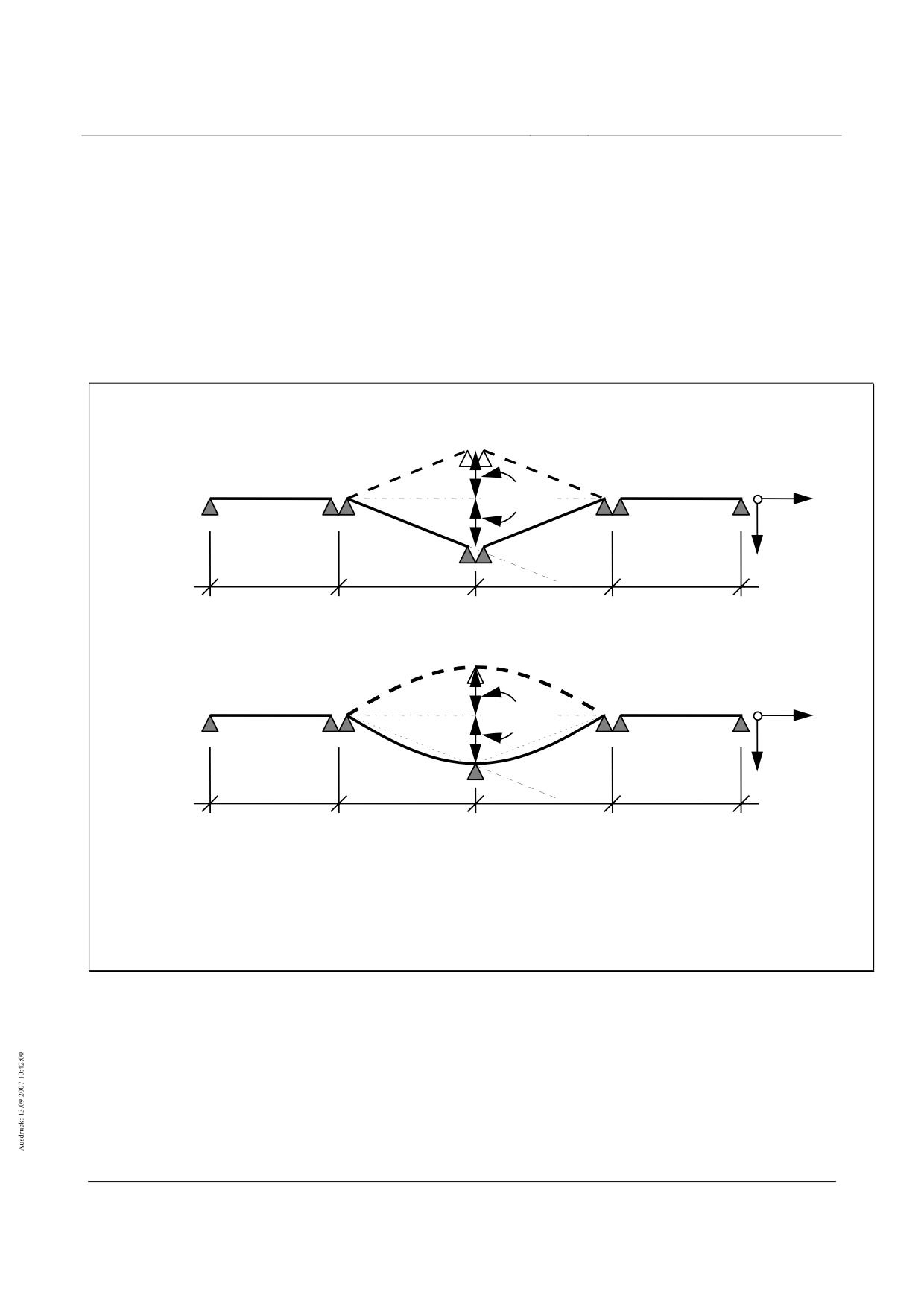
High-speed maglev systems
Maglev Technical Committee
Design principles
Guideway
Substructure deformation in the y direction
Plastic substructure deformation
(1)
The following limit values for guideway substructure deformation in the y direction must be observed
by both simple beams and multiple span girders:
( 38)
• Supports with girder joints:
∆ySt,1,plas = ± LSys / 6000
( 39)
• King posts in the case of multiple
∆ySt,2,plas = ± LSys / 4500
span girders:
(2)
When the limit value is exceeded, the support structure mounting must be readjusted.
Trägerstöße
(z.B. bei Einfeldträgern)
∆ySt,1,plas
z
x
y
LSys
LSys
LSys
LSys
Mittelstützen
(z.B. bei Zweifeldträgern)
∆ySt,2,plas
z
x
y
LSys
LSys
LSys
LSys
Fig. 158 - Plastic substructure deformation in the y direction (example)
[Key to diagram:
Tragerstöße (z.B. bei Einfeldträgern) = girder joints (e.g. in the case of simple beams)
Mittelstützen (z.B. bei Zweifeldträgern) = king posts (e.g. in the case of two-span beams)]
Elastic substructure deformation
(1)
The following limit values must be observed as regards the elastic deformation of substructures in the
y direction as a result of the variable effects Q1 ÷ Q10 and Q50 ÷ Q60:
Title
High-speed Maglev Systems - Design principles
Guideway - Part II: Design
Doc. no.:
57288
Version
White Paper Issue date
15.02.2007
Page 121
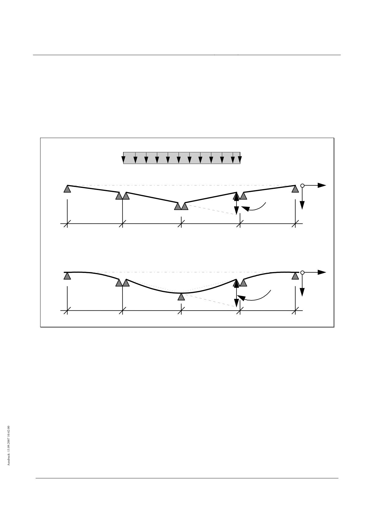
High-speed maglev systems
Maglev Technical Committee
Design principles
Guideway
( 40)
• Supports with girder joints:
∆ySt,1,elas = ± LSys · (0.0013 -1/ 6000) ⋅ k
( 41)
• King posts in the case of multiple span
∆ySt,2,elas = ± LSys · (0,0015 -1/ 4500) ⋅ k
girders:
where k = hG,Ground [m]/ 20 m, hG,Ground ≥ 3 m and k ≤ 1
Fahrzeug
Trägerstöße
(z.B. bei Einfeldträgern)
x
z
∆ySt,1,elas
y
LSys
LSys
LSys
LSys
Mittelstützen
(z.B. bei Zweifeldträgern)
x
z
∆ySt,2,elas
y
LSys
LSys
LSys
LSys
Fig. 159 - Elastic substructure deformation in the y direction (example 1)
[Key to diagram:
Fahrzeug = vehicle
Tragerstöße (z.B. bei Einfeldträgern) = girder joints (e.g. in the case of simple beams)
Mittelstützen (z.B. bei Zweifeldträgern) = king posts (e.g. in the case of two-span beams)]
Title
High-speed Maglev Systems - Design principles
Guideway - Part II: Design
Doc. no.:
57288
Version
White Paper Issue date
15.02.2007
Page 122
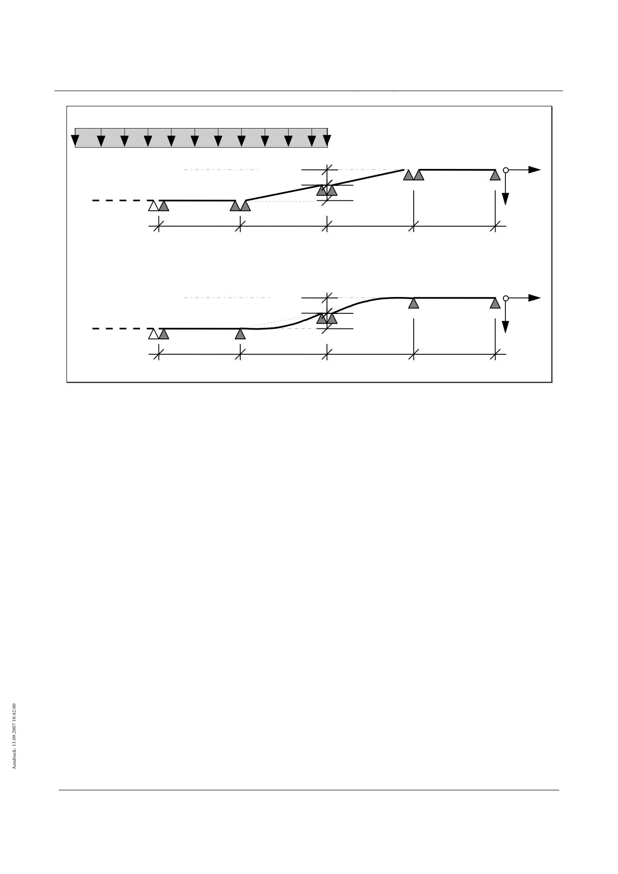
High-speed maglev systems
Maglev Technical Committee
Design principles
Guideway
Fahrzeug
Trägerstöße
∆ySt,1,elas
z
x
(z.B. bei Einfeldträgern)
∆ySt,1,elas
y
LSys
LSys
LSys
LSys
Mittelstützen
∆ySt,2,elas
z
x
(z.B. bei Zweifeldträgern)
∆ySt,2,elas
y
LSys
LSys
LSys
LSys
Fig. 160 - Elastic substructure deformation in the y direction (example 2)
[Key to diagram:
Fahrzeug = vehicle
Tragerstöße (z.B. bei Einfeldträgern) = girder joints (e.g. in the case of simple beams)
Mittelstützen (z.B. bei Zweifeldträgern) = king posts (e.g. in the case of two-span beams)]
Substructure deformation in the z direction
Plastic substructure deformation
(1)
The following limit values for plastic substructure deformation in the z direction (representation similar
to fig. 158) must be observed by both simple beams and multiple span girders:
( 42)
• Supports with girder joints:
∆zSt,1,plas = ± LSys / 6000
• King posts in the case of multiple
( 43)
∆zSt,2,plas = ± LSys / 4500
span girders:
(2)
When the limit value is exceeded, the support structure mounting must be readjusted.
Elastic substructure deformation
(1)
The following limit values must be observed as regards the elastic deformation of substructures in the
z direction as a result of the variable effects Q1 ÷ Q10 and Q50 ÷ Q60 (representation similar to figs.
159 and 160):
( 44)
• Supports with girder joints:
∆zSt,1,elas = ± LSys / 6000
( 45)
• King posts in the case of multiple
∆zSt,2,elas = ± LSys / 4500
span girders:
Title
High-speed Maglev Systems - Design principles
Guideway - Part II: Design
Doc. no.:
57288
Version
White Paper Issue date
15.02.2007
Page 123
High-speed maglev systems
Maglev Technical Committee
Design principles
Guideway
Deformation of continuous strip foundations
(1)
An assessment of the deformation of continuous strip foundations (e.g. the guideway plate) shall be
conducted in a particular case. As a rule in this regard, the limiting of permitted offsets at the functional
levels (stator, lateral guide and slider levels) is decisive (see Chapter 10.3.6).
(2)
The equations and figures from Chapter 10.3.8 are not applicable here.
Primary supporting framework deformation
(1)
The permitted deformation of primary supporting frameworks (e.g. viaducts with “laid” support structu-
res of low-lying/ground level design) shall be limited such that the abovementioned requirements per-
taining to
• the end tangent angle of rotation ϑ (see figs. 156 and 157),
• the gap dimensions and
• offsets
are satisfied.
(2)
Following agreement with the competent supervisory authority, taking into account the framework
condition whereby the guideway position on the primary supporting framework corresponds to the
standard camber of 100%, as regards primary supporting frameworks, the limit values for supporting
framework deflection in the z direction as set out in Chapter 10.3.2.2.1 may be doubled where justified
in exceptional circumstances (i.e. unstressed, 100% camber, 100% deflection under a load).
(3)
Proof must be furnished of the compatibility of primary supporting frameworks in relation to the vehicle.
Title
High-speed Maglev Systems - Design principles
Guideway - Part II: Design
Doc. no.:
57288
Version
White Paper Issue date
15.02.2007
Page 124
High-speed maglev systems
Maglev Technical Committee
Design principles
Guideway
Deformations in the event of collisions on the guideway
(1)
If a collision on the guideway is to be considered in accordance with Chapter 8.3.6, the offsets which
remain between the “functional levels” (stator levels, lateral guide rail levels) along girder joints follow-
ing a collision involving supports or support structures should not exceed 3 mm.
Metal fatigue
General
(1)
The general principles concerning the furnishing of proof of structural durability/fatigue evaluation (fa-
tigue classes with the associated stress-number line, partial safety coefficients of the resistance side,
etc.) shall be taken from EN 1990 and the respective standards and guidelines, as well as other per-
mitted regulations and the Guideway design principles for high-speed maglev systems - Part I: Princi-
ple requirements.
(2)
Selected parameters which are dependent on the structure shall be substantiated when proof is fur-
nished.
Framework conditions which are specific to high-speed maglev
systems
(1)
Unless otherwise stipulated in relation to a specific project, the following typical formulations apply to
the proofs concerning metal fatigue:
• vehicle weights Q1…Q4 and the appurtenant frequencies as per Chapter 8.2.1.2
•
130 journeys per traffic lane per day (basis: approx. 20 hours/day with 6 journeys/hour)
•
a service life of 80 years (365 days/year)
•
free lateral acceleration ay = - 0.5 m/s² … 1.5 m/s²
•
vertical acceleration (incl. g) az = 9.21 m/s² …11.01 m/s²
•
load in the x direction as per Table 101 with the option of a project-specific grading of the longitudi-
nal forces based on the propulsion design for a project-specific design (of the guideway substructu-
res, for instance)
• taking into account the dynamics as per Chapter 7.4
• taking into account the pertinent global/local load scenarios
• allowing for the travel dynamics (dynamic lateral forces) and constraint forces
• allowing for a head wind
• taking into consideration the numerous variable environmental effect values25
• taking into account the bending load of the points arising from the adjustment procedure to the
branch positions
• with increased vehicle weight as a result of snow (the frequency and size of the load shall be stipu-
lated in relation to the particular project)
• disregarding the effects of uncommon operational situations
• disregarding unusual influences
(2)
As regards the local support components at the points of intersection between the longitudinal stator
and the levitation magnet and the lateral guide rail and the guidance magnet, the conditions specified
in Chapters 10.4.3 and 10.4.4 apply.
Title
High-speed Maglev Systems - Design principles
Guideway - Part II: Design
Doc. no.:
57288
Version
White Paper Issue date
15.02.2007
Page 125
High-speed maglev systems
Maglev Technical Committee
Design principles
Guideway
Point of intersection between the longitudinal stator and the
levitation magnet
• the project-dependent design of the building components and assemblies as per Chapter 10.4.2;
• consideration of the levitation magnet pole division as per Chapter 7.3;
• where the building components and assemblies are designed independent of the project, the action limit
values must be taken into consideration.
• allowing for the structural and control dynamics;26
Point of intersection between the lateral guide rail and the
guidance magnet
• the project-dependent design of the building components and assemblies as per Chapter 10.4.2;
• the smallest device for considering the control dynamics is the part magnet (1525 mm). Interruptions in
the pole terminal strips in the x direction between two adjacent guidance magnets and within the guidan-
ce magnets are negligible;
• where the building components and assemblies are designed independent of the project, the action limit
values must be taken into consideration;
• allowing for the structural and control dynamics;27
Title
High-speed Maglev Systems - Design principles
Guideway - Part II: Design
Doc. no.:
57288
Version
White Paper Issue date
15.02.2007
Page 126
High-speed maglev systems
Maglev Technical Committee
Design principles
Guideway
Annex
Title
High-speed Maglev Systems - Design principles
Guideway - Part II: Design
Doc. no.:
57288
Version
White Paper Issue date
15.02.2007
Page 127

High-speed maglev systems
Maglev Technical Committee
Design principles
Guideway
Annex II-A: Allocation of the effects at the
points of intersection
No.
Effects resulting from the vehicle/drive
Comments
Common design situations
x
x
x
Q1
Forces of gravity, incl. dynamics arising from a vehicle’s own weight
Q2
Forces of gravity, incl. dynamics arising from the live load
x
x
x
x
x
x
Q3
Unequal distribution of the vehicle weight in the x direction
x
x
Q4
Unequal distribution of the vehicle weight in the y direction
Q5
Travel dynamics (dynamic forces arising from tracking)
x
x
Q6
Constraint forces in narrow radii
x
Q7a
Aerodynamic forces arising from train crossings
Q7b
Aerodynamic forces arising from journeys through tunnels
(x)
(x)
(x)
Q7c
Aerodynamic forces on structural works situated close to the guideway
x
Q8a
Effects of the head wind: lift
Q8b
Effects of the head wind: pressure/pull
(x)
(x)
(x)
x
x
x
Q9a
Lateral forces as a result of atmospheric wind
x
Q9b
Lift as a result of atmospheric wind
Q10
Temperature as a result of propulsion
x
Uncommon design situations
x
x
x
Q11a
Increased vehicle weight
x
Q11b
Failure of a magnet control circuit, support
x
Q11c
Double failure of magnet control circuits, support
x
Q11d
Failure of a magnet control circuit, guidance
x
Q11e
Double failure of magnet control circuits, guidance
Use of the “secure brake”
x
x
x
Q11f
x
x
(x)
Q11g
Speed fluctuations
x
(x)
Q11h
Propulsion mechanism malfunction
x
x
Q11i
Effects as a result of a motor short circuit
x
Q11j
Magnet start up
x
Q11k
Lifting up skid pads frozen to the guideway
x
x
x
Q11l
Increased vehicle weight as a result of snow in the vehicle
Unusual effects (analogous)
Table 115 - Assignment of effects to the functional levels
[Key to table:
SE = stator level
SFE = lateral guide rail level
Title
High-speed Maglev Systems - Design principles
Guideway - Part II: Design
Doc. no.:
57288
Version
White Paper Issue date
15.02.2007
Page 128
High-speed maglev systems
Maglev Technical Committee
Design principles
Guideway
GLE = slider level]
Title
High-speed Maglev Systems - Design principles
Guideway - Part II: Design
Doc. no.:
57288
Version
White Paper Issue date
15.02.2007
Page 129