Design Principles High-speed Maglev System. Information (MSB, 2007) - page 13
High-speed maglev systems
Maglev Technical Committee
Design principles
Guideway
wave deviation. The beginning and end of the girder of the first or final section, as well as
the support locations, shall be assigned the absolute value “0”.
It is assumed that deviations from “0” which may occur during production at the support lo-
cations are compensated during assembly and precise positioning.
• Determining the progression of the precurvature in the case of multiple span girder systems
(> 2 sections) does not constitute part of this document.
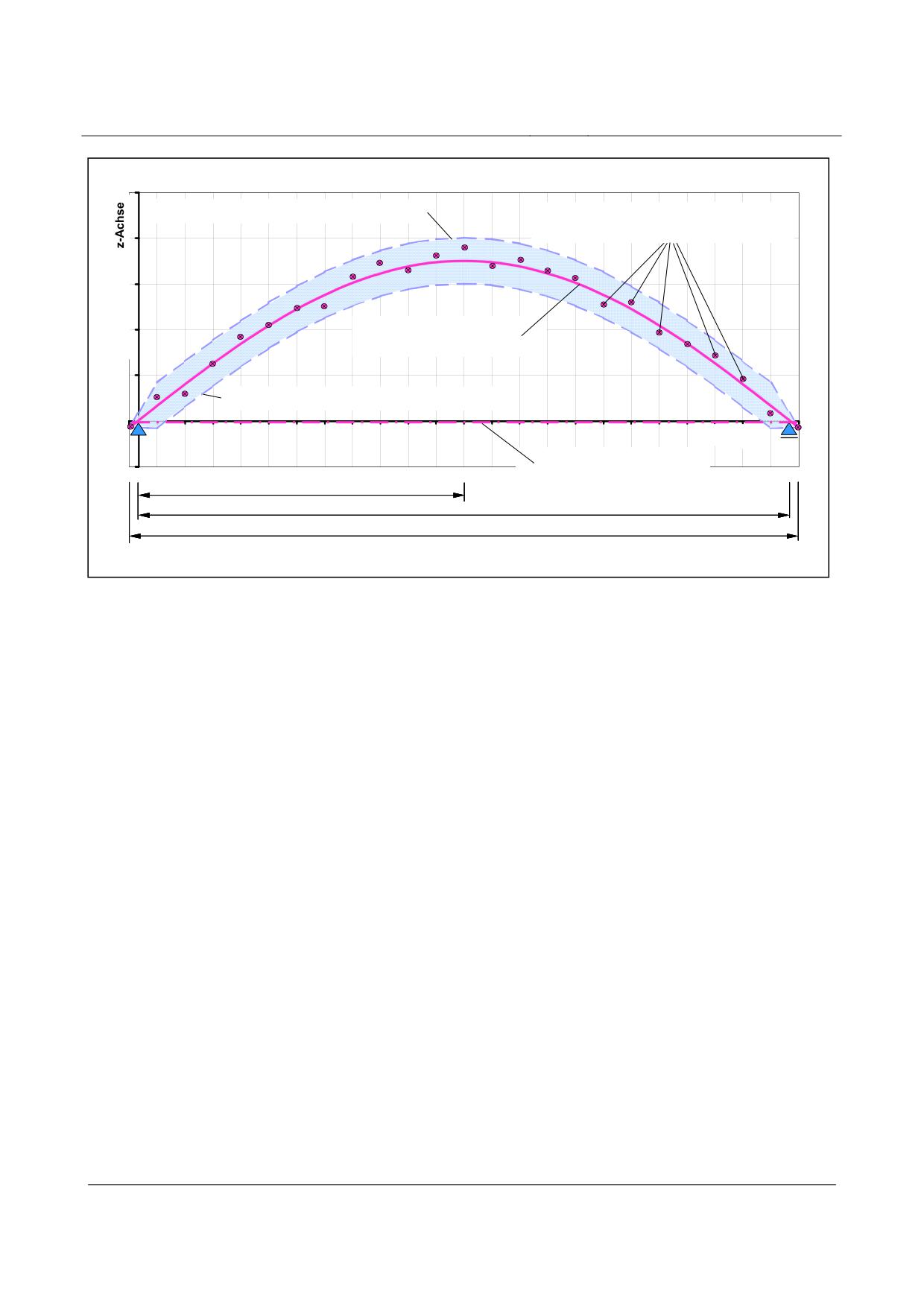
The actual location of the long-wave deviation (see fig. 199) may be determined from the continu-
ous measured values, taking the functions to be assumed as a basis (see above), using Gauss’ law of
errors and the method of least squares, or by means of areal compensation.
The actual progression determined in this way as a function f(x) of the functional level considered,
in conjunction with the superimposed tolerance zone of the short-wave deviation reflects the maxi-
mum possible deviations in terms of the continuous measured values from the actual location of the
long-wave deviation.
The possible progression of the actual position of the long-wave deviation is limited in this regard
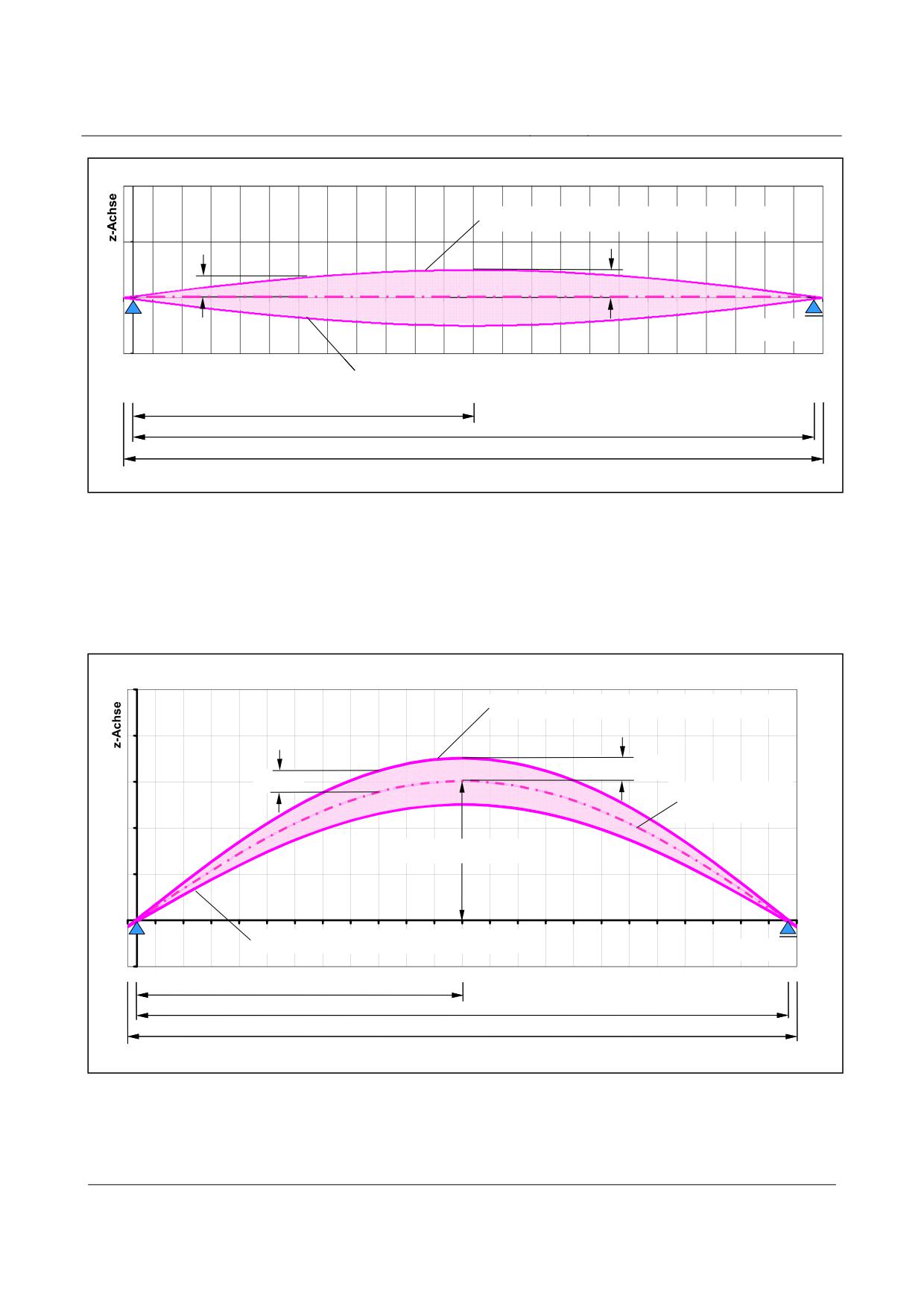
by the long-wave deviation tolerance zone (see figs. 201, 202 and 203).
Title
High-speed Maglev Systems - Design principles
Guideway - Part III: Geometry
Doc. no.:
41727
Version White Paper Issue date
15.02.2007
Page 27
High-speed maglev systems
Maglev Technical Committee
Design principles
Guideway
Obergrenze der kurzwelligen Abweichung
diskrete Meßwerte zur Ermittlung der
Ist - Lage der langwelligen Abweichung
Ist - Lage der
langwelligen Abweichung
Untergrenze der kurzwelligen Abweichung
x-Achse
Soll - Lage
(als Gerade dargestellt)
LSt/ 2
St
LSt
St
L
Fig. 199:
Correlation between continuous measured values, the actual location of the long-wave deviation and the
associated short-wave deviation limit values
[Key to diagram:
Obergrenze der kurzwelligen Abweichung = upper limit for short-wave deviation
diskrete Meßwerte zur Ermittlung der Ist-Lage der langwelligen Abweichung = continuous measured values
for determining the actual position of the long-wave deviation
Ist-Lage der langwelligen Abweichung = actual position of the long-wave deviation
Untergrenze der kurzwelligen Abweichung = lower limit for short-wave deviation
Soll-Lage (als Gerade dargestellt) = theoretical position (portrayed as a straight line)
x-Achse = x-axis
z-Achse = z-axis]
When determining the long-wave deviation, the projected ∆ zi of the gusset solution (Chapter 6.6.5)
must be taken into consideration when using the continuous measured values.
Long-wave deviation in the case of simple beams
The diagrams and equations below relating to the long-wave deviation tolerance zone have been
drawn up in relation to the z coordinates by way of example and can be applied, by analogy, to the
y coordinates.
As regards simple beams, long-wave deviation progression as regards the tolerance zone is descri-
bed by the following equation:
3
4
384
⎛
x
2*x
x
⎞
i
i
i
Equation 18
∆z
=±
max∆z
*
*
-
+
[mm]
i,Lw
Lw
⎜
3
4
⎟
120
L
L
L
⎝
⎠
Title
High-speed Maglev Systems - Design principles
Guideway - Part III: Geometry
Doc. no.:
41727
Version White Paper Issue date
15.02.2007
Page 28
High-speed maglev systems
Maglev Technical Committee
Design principles
Guideway
Obergrenze für die langwellige Abweichung
∆zi,Lw
max ∆ zLw
x-Achse
Untergrenze für die langwellige Abweichung
LSt/ 2
St
LSt
L
Fig. 200:
The progression and position of the long-wave deviation tolerance zone in the case of simple beams with-
out precurvature, using the example of the stator level
[Key to diagram:
Obergrenze für die langwellige Abweichung = upper limit for long-wave deviation
Untergrenze für die langwellige Abweichung = lower limit for long-wave deviation
x-Achse = x-axis
z-Achse = z-axis]
Obergrenze für die langwellige Abweichung
max ∆ zLw
∆zi,Lw
Soll-
Vorkrümmung
max. Sollvorkrümmung
Untergrenze für die langwellige Abweichung
x-Achse
LSt/ 2
LSt
L
Fig. 201:
The progression and position of the long-wave deviation tolerance zone in the case of simple beams with
precurvature, using the example of the stator level
[Key to diagram:
Obergrenze für die langwellige Abweichung = upper limit for long-wave deviation
Soll-Vorkrümmung = design precurvature
Title
High-speed Maglev Systems - Design principles
Guideway - Part III: Geometry
Doc. no.:
41727
Version White Paper Issue date
15.02.2007
Page 29
High-speed maglev systems
Maglev Technical Committee
Design principles
Guideway
max. Soll-Vorkrümmung = maximum design precurvature
Untergrenze für die langwellige Abweichung = lower limit for long-wave deviation
x-Achse = x-axis
z-Achse = z-axis]
Title
High-speed Maglev Systems - Design principles
Guideway - Part III: Geometry
Doc. no.:
41727
Version White Paper Issue date
15.02.2007
Page 30
High-speed maglev systems
Maglev Technical Committee
Design principles
Guideway
Long-wave deviation in the case of two-span beams and multiple span girders as
well as gauge change devices
The diagrams and equations below relating to the long-wave deviation tolerance zone have been
drawn up in relation to the z coordinates by way of example and can be applied, by analogy, to the
y coordinates.
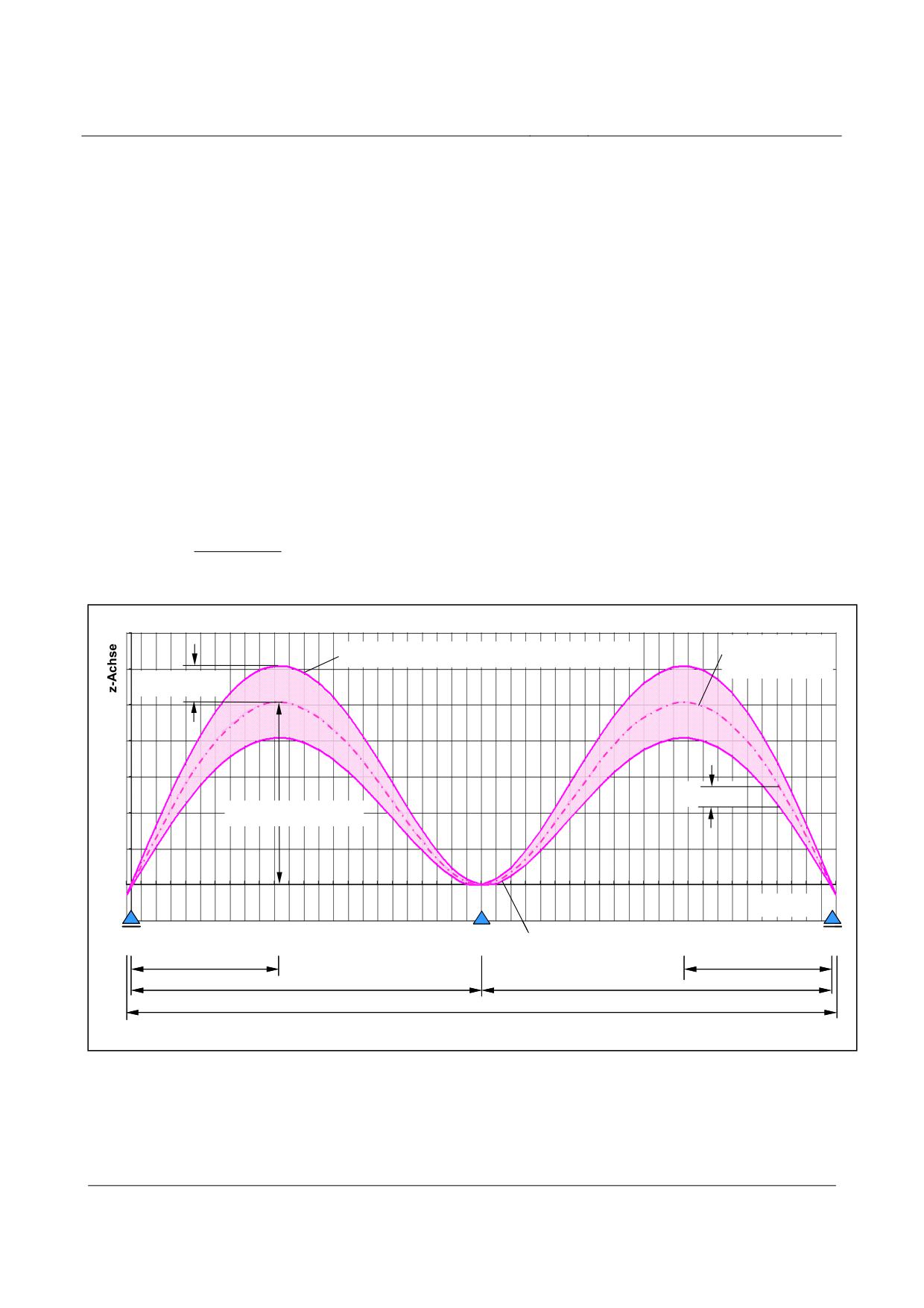
As regards two-span beams, long-wave deviation progression as regards the tolerance zone in the
area of the beginning or end of the girder as far as the centre support is described by the following
equation:
3
4
185
⎛
x
3*x
2*x
⎞
i
i
i
Equation 19
∆z
=±
max
∆z
*
*
-
+
[mm]
i,Lw
Lw
⎜
3
4
⎟
48
L
L
L
⎝
i
i
i
⎠
The following equation is used for a simplified determination of the long-wave deviation tolerance
zone in the case of bowed functional levels of simple and two-span beams between the beginning
or end of the girder and the centre support:
z
i,Soll
Equation 20
∆z
=±
[mm]
i,Lw
max z
Soll
Soll-
Obergrenze für die langwellige Abweichung
Vorkrümmung
max ∆ zLw
∆ z i, Lw
maxSollvorkrümmung
x-Achse
Untergrenze für die langwellige Abweichung
0,421* L St 1
0,421* L St 2
St 1
St 2
LSt 1
LSt 2
St 1
St 2
L = L1+ L212
Fig. 202:
The progression and position of the long-wave deviation tolerance zone in the case of two-span beams with
precurvature, using the example of the stator level
[Key to diagram:
Obergrenze für die langwellige Abweichung = upper limit for long-wave deviation
Soll-Vorkrümmung = design precurvature
max. Soll-Vorkrümmung = maximum design precurvature
Title
High-speed Maglev Systems - Design principles
Guideway - Part III: Geometry
Doc. no.:
41727
Version White Paper Issue date
15.02.2007
Page 31
High-speed maglev systems
Maglev Technical Committee
Design principles
Guideway
Untergrenze für die langwellige Abweichung = lower limit for long-wave deviation
x-Achse = x-axis
z-Achse = z-axis]
Soll-Lage der SE (= Gradientenverlauf)
Obergrenze für die langwellige Abweichung
max ∆ z i, Lw
∆ z i, Lw
x-Achse
Untergrenze für die langwellige Abweichung
LSt 1
LSt n
St 1
St n
L
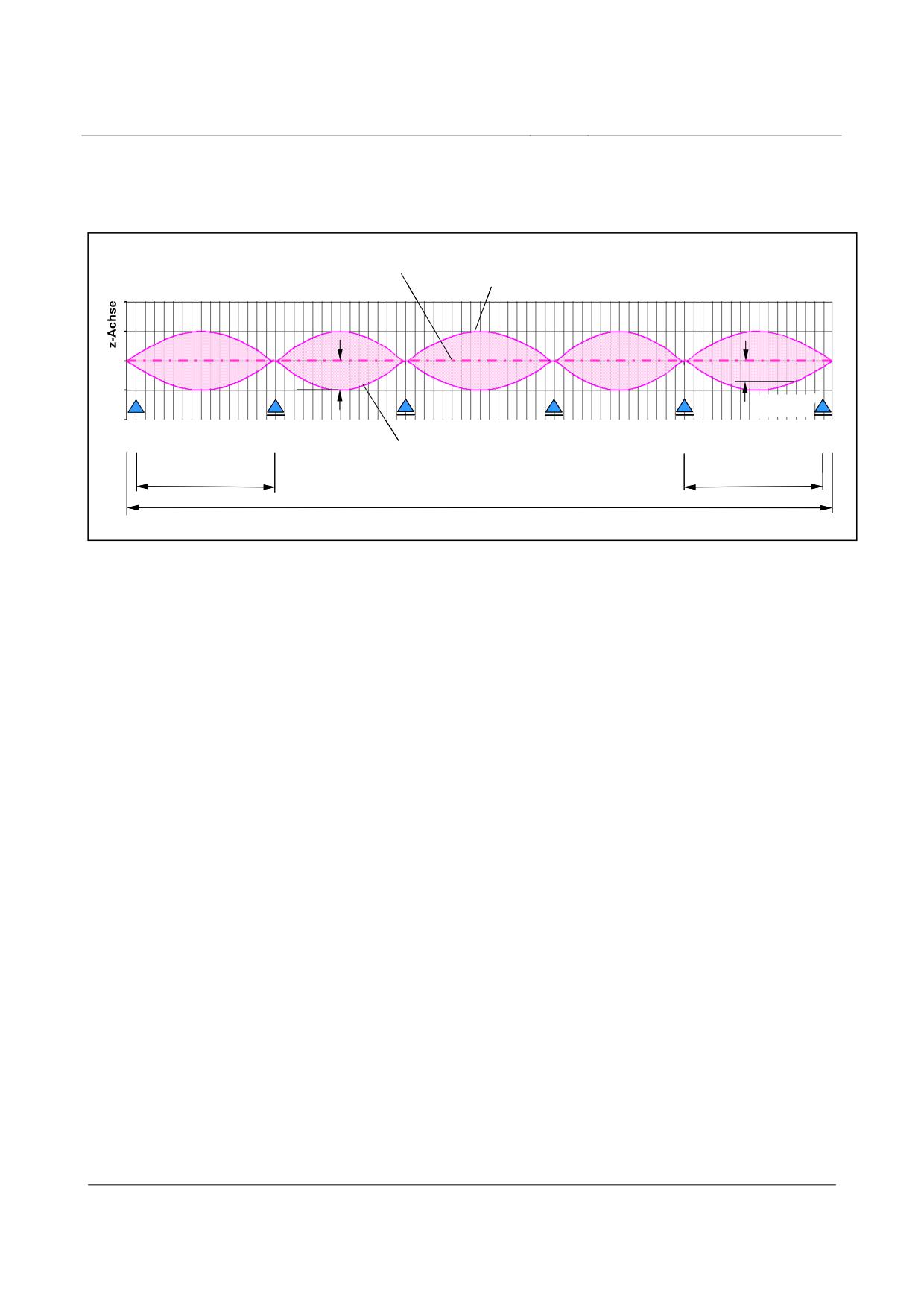
Fig. 203:
The progression and position of the long-wave deviation tolerance zone using the example of the stator
level of a gauge change device without design precurvature
[Key to diagram:
Soll-Lage der SE (= Gradientenverlauf) = theoretical position of the stator level (= progression of the gra-
dient)
Obergrenze für die langwellige Abweichung = upper limit for long-wave deviation
Untergrenze für die langwellige Abweichung = lower limit for long-wave deviation
x-Achse = x-axis
z-Achse = z-axis]
Short-wave deviation
Short-wave deviation superimposes the actual location of the long-wave deviation. It comprises all
tolerances as regards material, production and placement of those elements which determine the
functional levels.
All absolute values at the local measurement points of the functional area, as well as all areas be-
tween the individual measurement points, must lie within its tolerance zone.
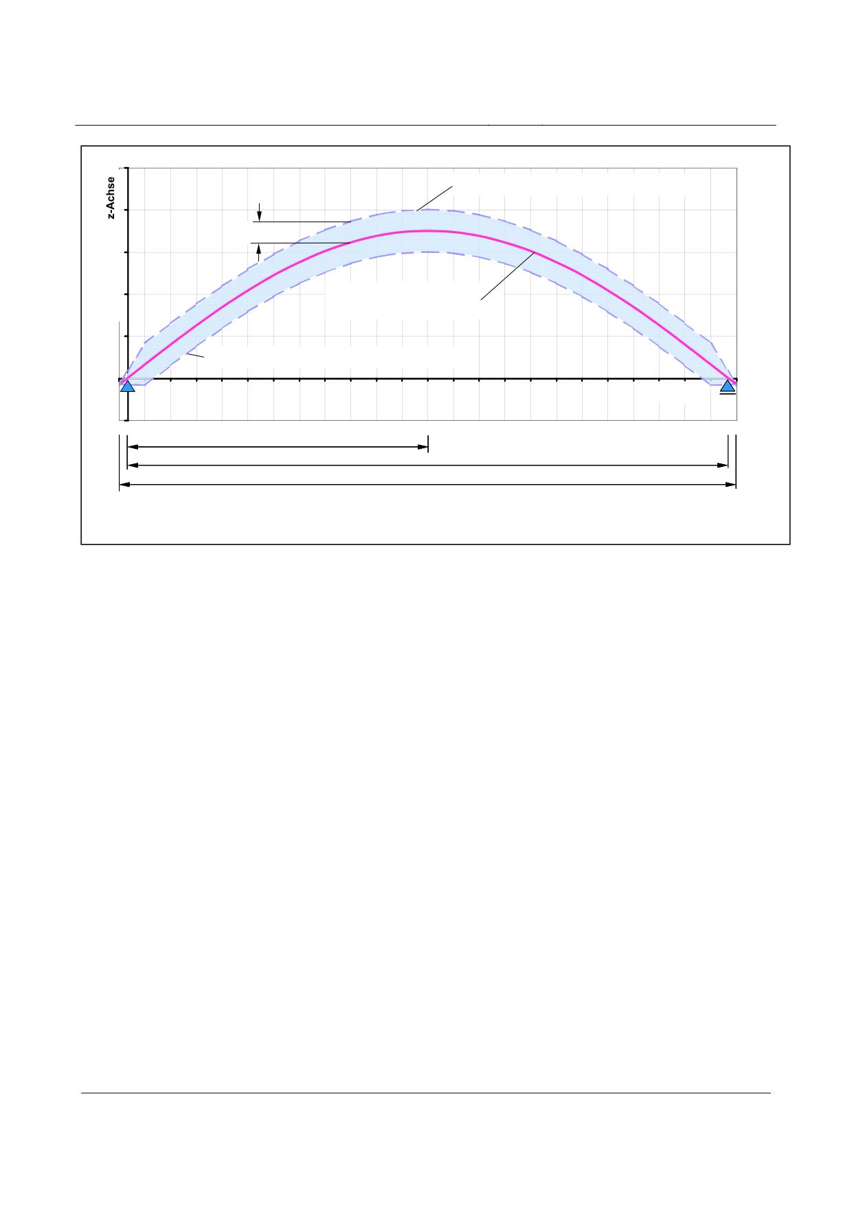
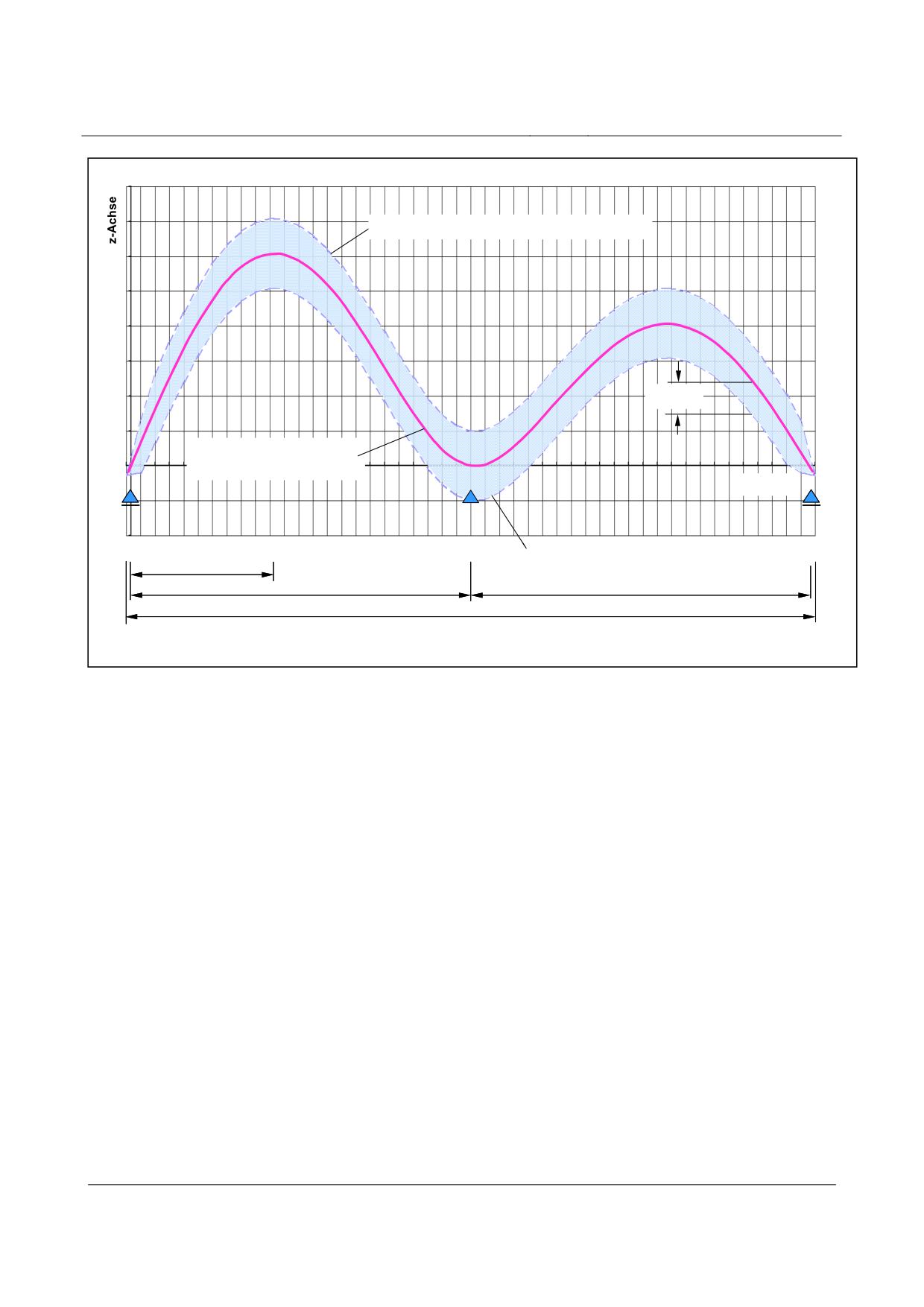
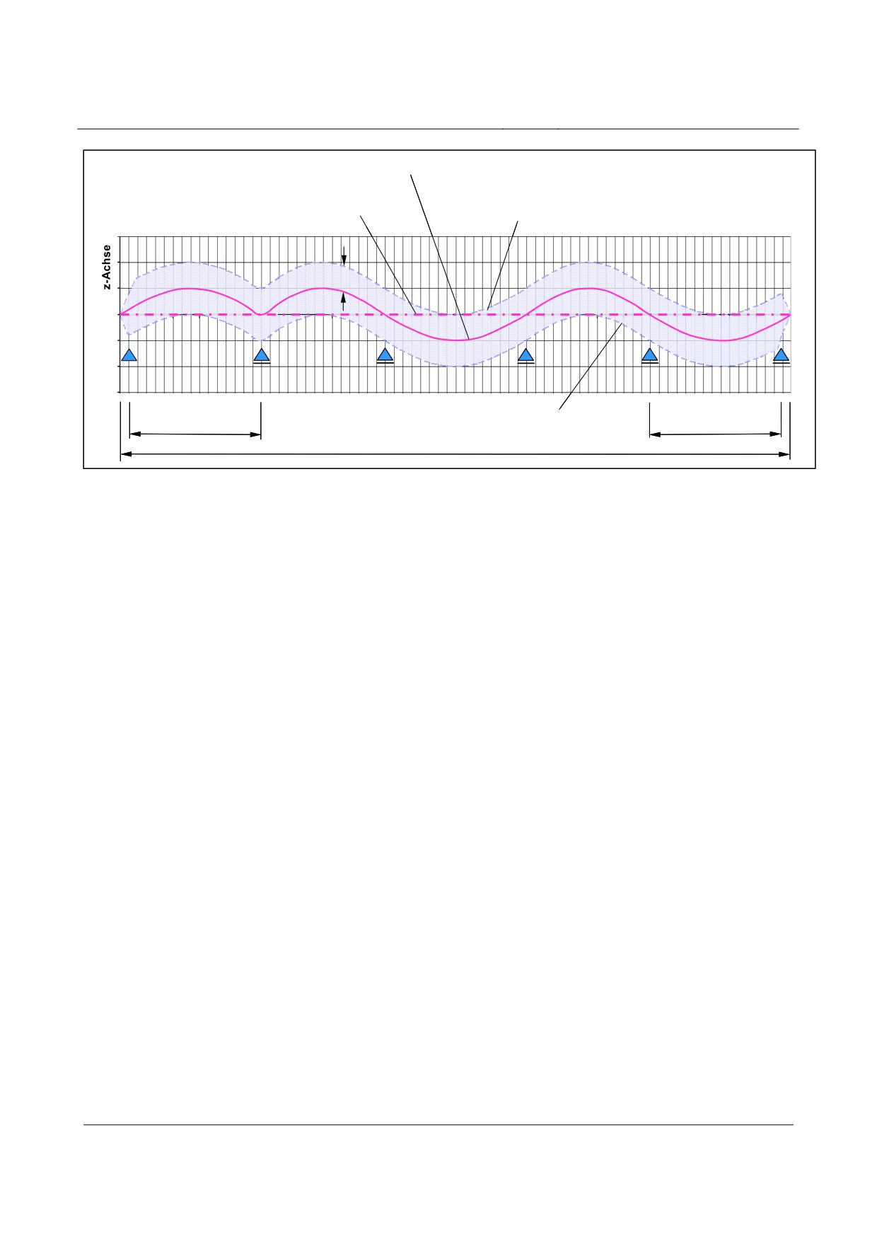
Up to the area of the immediate beginning and end of the girder, the tolerance width remains
constant over the length of the support structure (see also figs. 204, 205 and 206).
The design at the beginning and end of the girder is characterised by the gradient-altering criterion
which is permitted there (Chapter 6.6.5).
The diagrams below relating to short-wave deviation have been drawn up in relation to the z coor-
dinates by way of example and can be applied, by analogy, to the y coordinates.
Title
High-speed Maglev Systems - Design principles
Guideway - Part III: Geometry
Doc. no.:
41727
Version White Paper Issue date
15.02.2007
Page 32
High-speed maglev systems
Maglev Technical Committee
Design principles
Guideway
Obergrenze der kurzwelligen Abweichung
∆zi,Kw
Ist - Lage der
langwelligen Abweichung
Untergrenze der kurzwelligen Abweichung
x-Achse
LSt/ 2
St
LSt
St
L
Fig. 204:
Tolerance zone progression of the short-wave deviation in the case of simple beams with precurvature,
using the example of the stator level
[Key to diagram:
Obergrenze der kurzwelligen Abweichung = upper limit for short-wave deviation
Ist-Lage der langwelligen Abweichung = actual position of the long-wave deviation
Untergrenze der kurzwelligen Abweichung = lower limit for short-wave deviation
x-Achse = x-axis
z-Achse = z-axis]
Title
High-speed Maglev Systems - Design principles
Guideway - Part III: Geometry
Doc. no.:
41727
Version White Paper Issue date
15.02.2007
Page 33
High-speed maglev systems
Maglev Technical Committee
Design principles
Guideway
Obergrenze der kurzwelligen Abweichung
∆zi, Kw
Ist - Lage der
langwelligen Abweichung
x-Achse
Untergrenze der kurzwelligen Abweichung
0,421*LSt1
St1
LSt1
LSt2
St1
St2
L
Fig. 205:
Tolerance zone progression of the short-wave deviation in the case of two-span beams with design precur-
vature and reference to the actual location of the long-wave deviation, using the example of the stator level
[Key to diagram:
Obergrenze der kurzwelligen Abweichung = upper limit for short-wave deviation
Ist-Lage der langwelligen Abweichung = actual position of the long-wave deviation
Untergrenze der kurzwelligen Abweichung = lower limit for short-wave deviation
x-Achse = x-axis
z-Achse = z-axis]
Title
High-speed Maglev Systems - Design principles
Guideway - Part III: Geometry
Doc. no.:
41727
Version White Paper Issue date
15.02.2007
Page 34
High-speed maglev systems
Maglev Technical Committee
Design principles
Guideway
Ist - Lage der langwelligen
Abweichung
Soll-Lage der SE (= Gradientenverlauf)
Obergrenze der kurzwelligen Abweichung
∆ z i, Kw
x-Achse
Untergrenze der kurzwelligen Abweichung
LSt 1
LSt n
St 1
St n
L
Fig. 206:
Tolerance zone progression of the short-wave deviation of a gauge change device with reference to the
actual location of the long-wave deviation, using the example of the stator level
[Key to diagram:
Ist-Lage der langwelligen Abweichung = actual position of the long-wave deviation
Soll-Lage der SE (= Gradientenverlauf) = theoretical position of the stator level (= progression of the gra-
dient)
Obergrenze der kurzwelligen Abweichung = upper limit for short-wave deviation
Untergrenze der kurzwelligen Abweichung = lower limit for short-wave deviation
x-Achse = x-axis
z-Achse = z-axis]
Gradient-altering criterion
The angle deviation in mm, determined at the measurement points defined under point 6.1 of two
adjacent 1 m long part elements of a functional level moving lengthwise along the guideway (x a-
xis), constitutes the gradient-altering criterion.
When assessing the gradient-altering criterion, the following approach shall be assumed:
When examining tolerances, a gradient-altering criterion which is to be found in the girder
may be regarded as constant depending on operation and temperature.
However, the gradient-altering criterion at the girder transition has the following properties:
• a fixed girder production portion which is determined by the portion from the design pre-
curvature and the tolerance range definition of the short-wave deviation at the beginning or
end of the girder,
• additionally, a variable portion which is dependent on the deformation of the girder under
the effects of load and temperature at the place of installation during the period of operati-
on.
This means that, depending on the deformation characteristics of the girder, the tolerance zones
for short-wave deviation at the beginning or end of the girder shall be stipulated in observance of
the system-related contractual limit values (refer to the Principles concerning the overall system
design of high-speed maglev systems).
Title
High-speed Maglev Systems - Design principles
Guideway - Part III: Geometry
Doc. no.:
41727
Version White Paper Issue date
15.02.2007
Page 35
High-speed maglev systems
Maglev Technical Committee
Design principles
Guideway
As a rule, the permitted gradient-altering criterion at the beginning and end of the girder should
not exceed half the permitted value in the support structure, relative to the theoretical position (ta-
king account of the design precurvature).
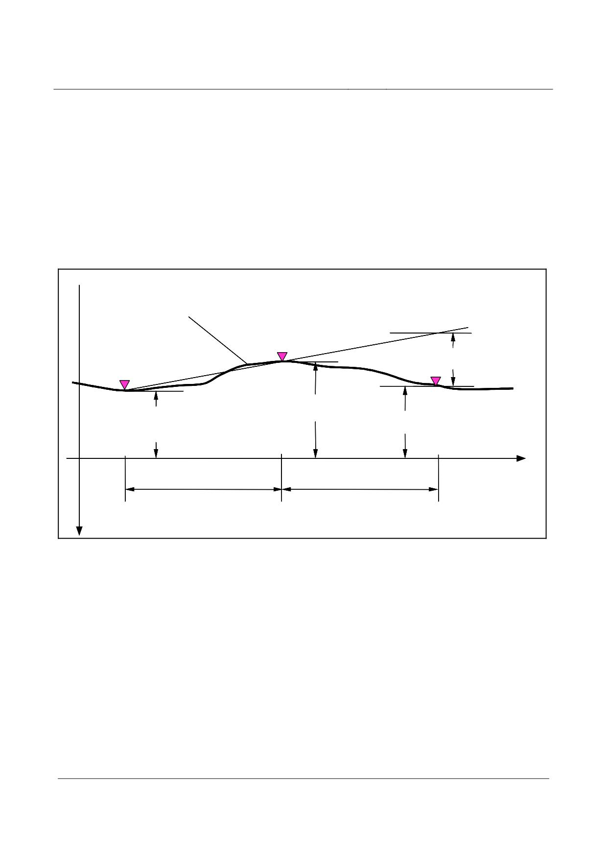
Criteria concerned with altering the incline are determined in accordance with equation 21, see fig.
207.
The equation is presented using the z coordinates as an example
⎡⎛
z
-z
⎞
⎛
z
−z
⎞⎤
i i-1
i i+1
Equation 21
NGK
=
+
i
⎢⎜
⎟
⎜
⎟⎥
⎣⎝
L
1
⎠
⎝
L
2
⎠⎦
Verlauf der GE-Oberfläche
Messpunkt i
NGKi, GLE
Messpunkt i-1
Messpunkt i+1
Zi
i
Zi + 1
Zi - 1
i + 1
1
L1
L2
x-Achse
z-Achse
Fig. 207:
Depiction of the gradient-altering criterion using the example of the slider level
[Key to diagram:
Verlauf der GE-Oberfläche = progression of the slider level surface
Messpunkt = measuring point
x-Achse = x-axis
z-Achse = z-axis]
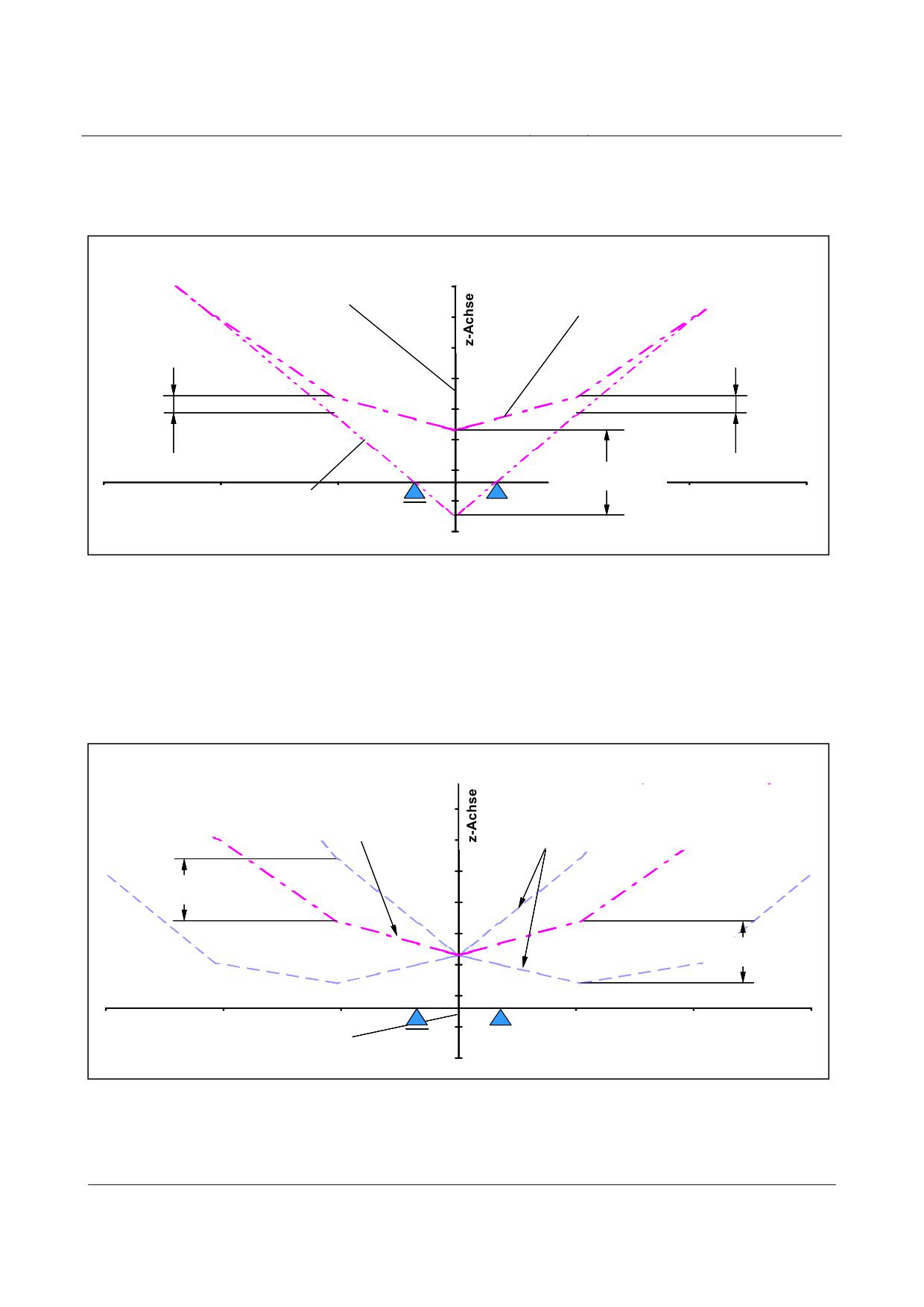
Gusset solution
To adapt the short-wave deviation tolerance zone at the beginning and end of the girder with the
aim of observing the gradient-altering criterion of the functional level (according to the Principles
concerning the overall system design of high-speed maglev systems) under all operating conditions
(the maximum actual temperature differential between the top and bottom booms of the girder; gir-
der geometry with loaded and unloaded girders), the position of the functional level at the begin-
ning and end of the girder can be optimised using the gusset solution. The x axis measurement
points constitute the reference point (see fig. 185).
Title
High-speed Maglev Systems - Design principles
Guideway - Part III: Geometry
Doc. no.:
41727
Version White Paper Issue date
15.02.2007
Page 36
High-speed maglev systems
Maglev Technical Committee
Design principles
Guideway
The gusset solution is currently only applied at the stator level, depending on the rigidity of the
girder in the z direction.
The procedure, in principle, for stipulating the theoretical position is evident from fig. 208.
Verlauf der Soll-Vorkrümmung
System-Achse am Trägerstoß
unter Berücksichtigung der Zwickellösung
∆ Z i -1,Zw
∆ Z i+1,Zw
max ∆ Z i,Zw
x-Achse
Verlauf der Soll-Vorkrümmung
Fig. 208:
Gusset solution design in the stator level
[Key to diagram:
System-Achse am Trägerstoß = system axis at the girder joint
Verlauf der Soll-Vorkrümmung unter Berücksichtigung der Zwickellösung = progression of the design precur-
vature, taking into account the gusset solution
Verlauf der Soll-Vorkrümmung = progression of the design precurvature
x-Achse = x-axis
z-Achse = z-axis]
Verlauf der Soll-Vorkrümmung
Verlauf der kurzwelligen Abweichung
am Trägerstoß
am Trägerstoß
unter Berücksichtigung der Zwickellösung
unter Berücksichtigung der Zwickellösung
∆Zi,Kw
∆Zi,Kw
x-Achse
Z-Achse entspr. System-Achse am Trägerstoß
Fig. 209:
Short-wave deviation progression of the stator level at the girder transition when applying the gusset solu-
tion
[Key to diagram:
Verlauf der Soll-Vorkrümmung am Trägerstoß, unter Berücksichtigung der Zwickellösung = progression of
the design precurvature along the girder joint, taking into account the gusset solution
Title
High-speed Maglev Systems - Design principles
Guideway - Part III: Geometry
Doc. no.:
41727
Version White Paper Issue date
15.02.2007
Page 37
High-speed maglev systems
Maglev Technical Committee
Design principles
Guideway
Verlauf der kurzwelligen Abweichung am Trägerstoß, unter Berücksichtigung der Zwickellösung = progressi-
on of the short-wave deviation along the girder joint, taking into account the gusset solution
Z-Achse entspr. System-Achse am Trägerstoß = z-axis corresponding to the system axis at the girder joint
x-Achse = x-axis
z-Achse = z-axis]
Giving consideration to the gusset solution at the time the girder is manufactured leads to a displa-
cement of the short-wave deviation tolerance zone in the girder start and end area, see fig. 209.
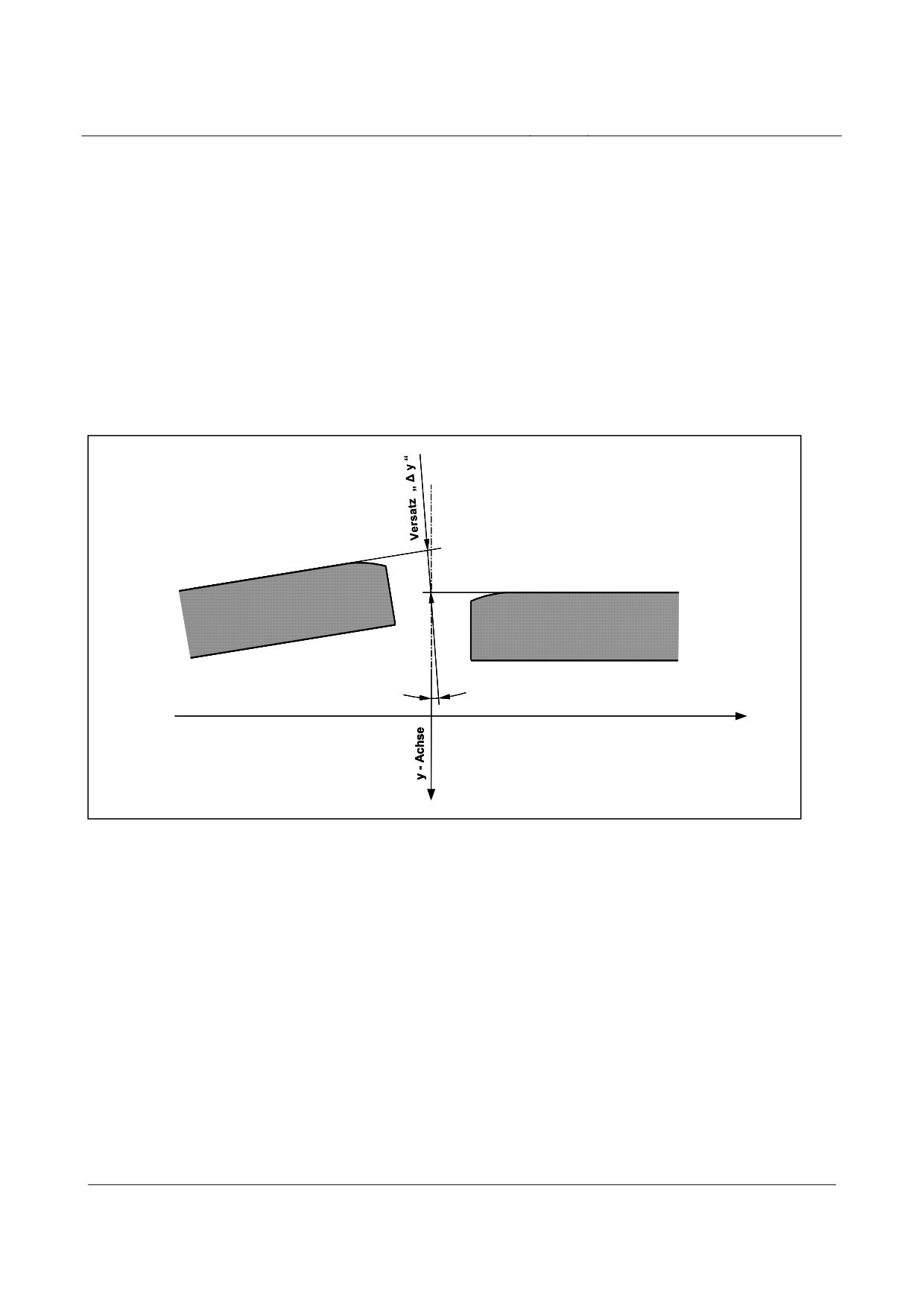
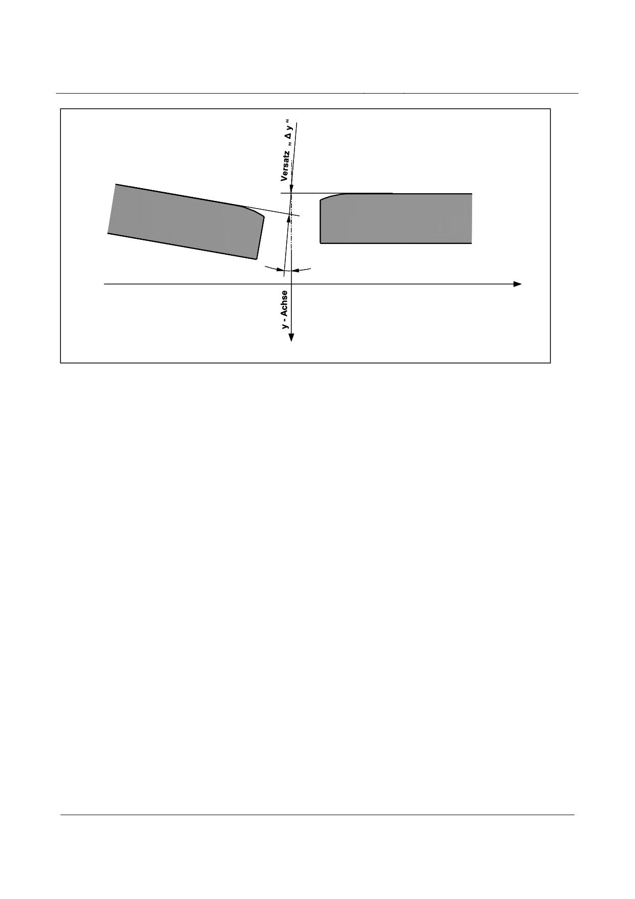
Displacement
The difference between the absolute values of two adjacent functional level elements at the immedi-
ate transition is designated as displacement, see figs. 210 and 211.
NGK/2
x - Achse
Fig. 210:
Presentation of negative displacement at the lateral guide rail level with superimposed gradient-altering
criterion
[Key to diagram:
Versatz = displacement
NGK = gradient-altering criterion
x-Achse = x-axis
y-Achse = y-axis]
Title
High-speed Maglev Systems - Design principles
Guideway - Part III: Geometry
Doc. no.:
41727
Version White Paper Issue date
15.02.2007
Page 38
High-speed maglev systems
Maglev Technical Committee
Design principles
Guideway
NGK/2
x - Achse
Fig. 211:
Presentation of positive displacement at the lateral guide rail level with superimposed gradient-altering
criterion
[Key to diagram:
Versatz = displacement
NGK = gradient-altering criterion
x-Achse = x-axis
y-Achse = y-axis]
Tilting
Functional level torsion at the measurement point (fig. 185) around the functional level longitudi-
nal axis (x axis) is described as tilting.
Lateral incline tolerance
If a functional level or geometric parameter, such as the lateral incline of the guideway, is made up
of two or more part areas (e.g. right and left stator levels), the lateral incline tolerance reflects the
deviation in the mean actual locations (e.g. zi,Ist) of the respective part areas at the same reference
point xi, from the theoretical position.
The lateral incline tolerance is only defined within the girder and comprises the actual progressions
of the short-wave deviation tolerance range of the functional levels in question.
Superimposition of tolerances and positional deviations
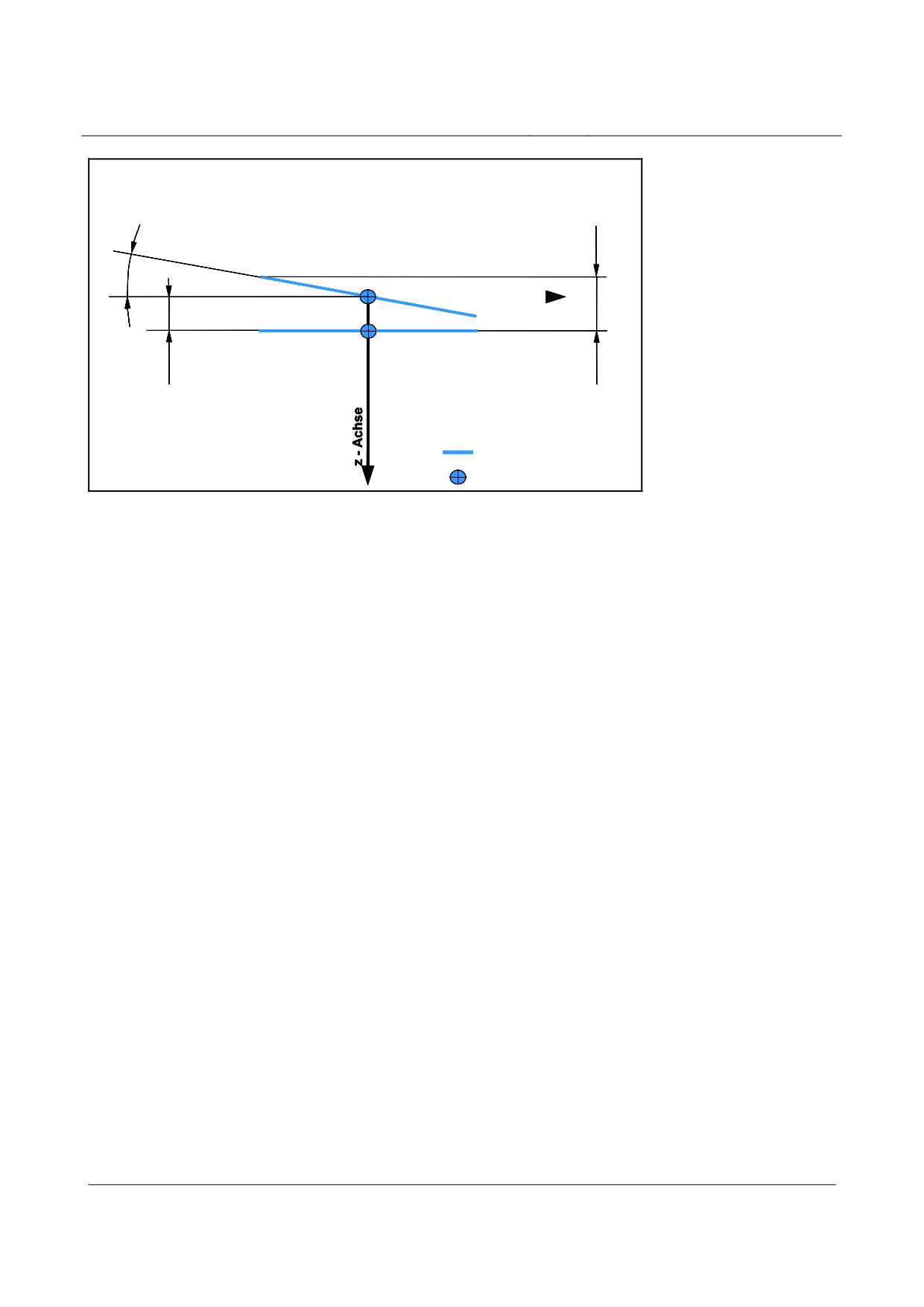
The positional deviations and tolerances listed in the preceding chapters are defined in relation to
the measurement point each time. Consequently, displacement which is considered, for instance,
over the entire extension of the functional level in the y direction, is the sum of the displacement
portions and the associated tilting portion (see fig. 212).
Gradient-altering criteria values only reflect the actual angle deviation of adjacent functional le-
vels, excluding any additional displacements which may be present (see figs. 210 and 211).
Title
High-speed Maglev Systems - Design principles
Guideway - Part III: Geometry
Doc. no.:
41727
Version White Paper Issue date
15.02.2007
Page 39
High-speed maglev systems
Maglev Technical Committee
Design principles
Guideway
Verkippung „ ∆ α“
max. Versatz „ ∆ z “
bezogen auf den
über die Breite der
Meßpunkt
Funktionsebene
y - Achse
Versatz „ ∆ z “
bezogen auf den
Meßpunkte
Funktionsebene
Meßpunkt (Kap. 5.1)
Fig. 212:
Superimposition of displacement and tilting along the same adjacent functional levels (e.g. in the case of
stator plates in the stator level)
[Key to diagram:
Verkippung “Uα” bezogen auf den Meßpunkt = tilting “Uα” relative to the measuring point
max. Versatz “U z” über die Breite der Funktionsebene = maximum displacement “U z” over the width of the
functional level
Versatz “U z” bezogen auf den Meßpunkt = displacement “U z” relative to the measuring point
Funktionsebene = functional level
Meßpunkt (Kap. 5.1) = measuring point (chapter 5.1)
y-Achse = y-axis
z-Achse = z-axis]
The mutual influence exerted by the individual positional deviations and tolerances is presented in
summary form in the following chapters in relation to the functional levels each time.
Title
High-speed Maglev Systems - Design principles
Guideway - Part III: Geometry
Doc. no.:
41727
Version White Paper Issue date
15.02.2007
Page 40
High-speed maglev systems
Maglev Technical Committee
Design principles
Guideway
Permitted tolerance and positional deviations
Stator level tolerances and positional deviations
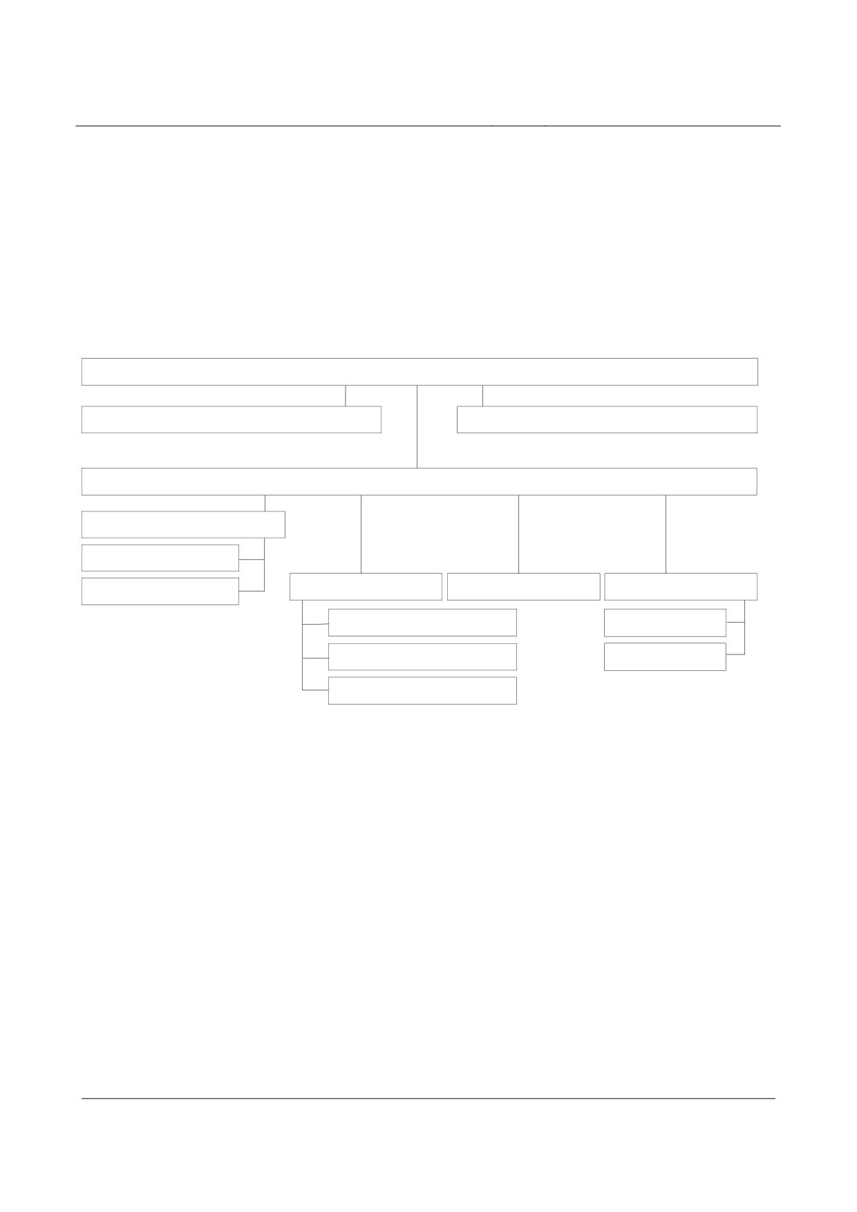
The mutual influence exerted by the individual stator level tolerances and positional deviations in
the z coordinates is presented in the following overview (fig. 213).
The x and y coordinate correlations were not presented given their secondary importance.
Lage der SE im MKS
Montagetoleranz des FW-Trägers bei der Ausrichtung zu einem bereits
Montagetoleranz des FW-Trägers, freies Ausrichten im MKS
montierten FW-Träger
Z-Koordinaten der SE im Trägerkoordinatensystem (bei der Fertigung)
Abweichung der rechten zur linken SE eines
Trägers in Z-Richtung
zulässige Verkippung der Statorpakete
um ihre X-Achse
kurzwellige Abweichung
langwellige Abweichung
Soll-Vorkrümmung in Z-Richtung
Querneigungstoleranz
Neigungsänderungskriterium benachbarter
zu berücksichtigendes ∆T
Statorpakete
to/tu
zulässiger Versatz benachbarter Statorpakete
zulässige Durchbiegung
in Z-Richtung
Zwickellösung am Trägeranfang und -ende
Fig. 213:
Stator level tolerances and positional deviations and their mutual dependence
[Key to diagram:
Lage der SE im MKS = position of the stator level in the maglev train coordinate system
Montagetoleranz des FW-Trägers bei der Ausrichtung zu einem bereits montierten FW-Träger = assembly
tolerance of the guideway girder in the case of alignment with a guideway girder which has already been
installed
Montagetoleranz des FW-Trägers, freies Ausrichten im MKS = assembly tolerance of the guideway girder,
free alignment in the maglev train coordinate system
Z-Koordinaten der SE im Trägerkoordinatensystem (bei der Fertigung) = z-coordinates of the stator level in
the girder coordinate system (during production)
Abweichung der rechten zur linken SE eines Trägers in Z-Richtung = deviation between the right and left
stator levels of a girder in the z direction
zulässige Verkippung der Statorpakete um ihre X-Achse = permitted tilting of the stator plates about its x-
axis
Querneigungstoleranz = permitted variation in the lateral incline
kurzwellige Abweichung = short-wave deviation
langwellige Abweichung = long-wave deviation
Soll-Vorkrümmung in Z-Richtung = design precurvature in the z direction
Title
High-speed Maglev Systems - Design principles
Guideway - Part III: Geometry
Doc. no.:
41727
Version White Paper Issue date
15.02.2007
Page 41
High-speed maglev systems
Maglev Technical Committee
Design principles
Guideway
Neigungsänderungskriterium benachbarter Statorpakete = gradient-altering criterion of adjacent stator plates
zu berücksichtigendes U T to/tu = U T to/tu to be considered
zulässiger Versatz benachbarter Statorpakete in Z-Richtung = permitted displacement in adjacent stator
plates in the z direction
zulässige Durchbiegung = permitted bending
Zwickellösung am Trägeranfang und -ende = spandrel solution at the beginning and end of the girder]
Permitted positional deviation of the stator plates in the x direction
The theoretical position of the individual stator plates in the support structure and, consequently,
their positioning in the x direction, are stipulated in relation to the project, taking into consideration
the Principles concerning the overall system design of high-speed maglev systems.
Moreover, at the support structure crossovers, the envisaged position of the motor winding cable
must be observed.
The manufacturing tolerances for incorporating the stator plates shall be selected in such a way that
when observing the stipulations set out in the Guideway design principles for high-speed maglev
systems - Part II: Dimensioning (guideway load and deformation), adjacent stator plates in the x
direction shall remain free from contact. In the girder section, the mechanical gaps at the sides of
the stator plates should be 0.5 to 2 mm.
Title
High-speed Maglev Systems - Design principles
Guideway - Part III: Geometry
Doc. no.:
41727
Version White Paper Issue date
15.02.2007
Page 42
High-speed maglev systems
Maglev Technical Committee
Design principles
Guideway
Permitted positional deviation of the centre axis of the longitudinal stator in the y
direction
The permitted positional deviation of the centre axis of the longitudinal stator (see fig. 185) in the y
direction in relation to the theoretical position is uniformly
∆
y
=
±2 mm
max
Stator level tolerances in the z direction
Design precurvature
The theoretical progression between the support axes of simple and two-span beams can be deter-
mined in accordance with equations 16 or 17. Similar equations concerning deflection shall be used
for multiple span elements. The deflection which is characteristic of the respective girder under a
vehicle load shall be calculated as zmax.
The permitted deflection is determined in accordance with the Guideway design principles for high-
speed maglev systems - Part II: Dimensioning.
When calculating the design precurvature, consideration must be given to the deformation in the
girder as a result of the difference in temperature within the girder cross-section ∆TBe according to
the Guideway design principles for high-speed maglev systems - Part II: Dimensioning.
Long-wave deviation in the stator level
The long-wave deviation tolerance zone progression relative to the progression of the design pre-
curvature is described as follows depending on the design of the girder:
Simple beams
x
<
x
<
x
⇒ equations 18 or 20
Trägeranfang
i
Trägerende
∆z i,Lw
Two-span beams
x
≤x
≤x
⇒ equations 19 or 20
Trägeranfang
i
L
1
∆zi,Lw
x
≤x
≤x
⇒ equations 19 or 20
L
2
i
Trägerende
∆zi,Lw
When using equations 18 and 19 to determine the upper and lower limits
max∆z
=1mm
Lw
shall be used.
Title
High-speed Maglev Systems - Design principles
Guideway - Part III: Geometry
Doc. no.:
41727
Version White Paper Issue date
15.02.2007
Page 43
High-speed maglev systems
Maglev Technical Committee
Design principles
Guideway
Multiple span girders (gauge change devices)
x
≤x
≤x
Trägeranfang
i
L
1
∆zi,Lw⇒ follows the mathematical description of the elastic
line *
x
≤x
≤x
L
1
i
L
n
∆zi,Lw⇒ follows the mathematical description of the elastic
line *
x
≤x
≤x
L
n
i
Trägerende
∆zi,Lw⇒ follows the mathematical description of the elastic
line *
* see Chapter 6.6.2;
max∆z
= 1mm i = number of sections
i,Lw
Short-wave deviation in relation to the actual location of the stator level (long-wave devia-
tion), tolerances at the girder joint
The short-wave deviation tolerance zone progression relative to the progression of the actual long-
wave deviation is described by the following basic data in a standard manner for the simple beam
and multiple span girder:
x
;
x
∆z=0
Trägeranfang
Trägerende
x
<
x
<
x
;
x
<
x
<
x
, n = 1, 2..* ∆
z
≤±1mm
Trägeranfang
i
0+n*1032
L-n*1032
i
Trägerende
i
x
<
x
<
x
∆z = ±1mm
0
+n*1032
i
L-n*1032
* n shall be stipulated in observance of the maximum permitted gradient-altering criterion
Gradient-altering criterion within the short-wave deviation
Within the short-wave deviation tolerance zone, to protect the proximity relation, a gradient-altering
criterion of
NGK
≤ 1,5mm
SE
must be observed in the stator level.
For determining the tolerance zone progression of the stator level at the beginning and end of the
girder (girder transition), consideration must be given to the system-related limit values set out in
the Principles concerning the overall system design of high-speed maglev systems and the permit-
ted limit values from the Guideway design principles for high-speed maglev systems - Part II: Di-
mensioning.
Relative to the theoretical progression of the functional level, a gradient-altering criterion of
NGK
≤ 0,75mm
SE,Anfang;Ende
shall be specified as a starting point.
As regards the gradient-altering criterion to be defined at these points for inspection and acceptance
measurements, the measurement conditions and references must be specified unconditionally.
Title
High-speed Maglev Systems - Design principles
Guideway - Part III: Geometry
Doc. no.:
41727
Version White Paper Issue date
15.02.2007
Page 44
High-speed maglev systems
Maglev Technical Committee
Design principles
Guideway
Permitted stator level displacements / tilting
The following tolerances relate to the measurement points according to fig. 185. In the x direction,
the first and last full-depth tooth of the adjacent stator plates are used as the measurement point
each time (see Chapter 6.1).
The tolerances are the same for all guideway designs.
• Displacements:
within the girder
∆z
=
0,4mm
i
max
at the girder joint
∆z
=
0,6mm
i
max
Displacement at the girder joint in this regard is purely an assembly tolerance which is only
adjusted following precise positioning of the girder.
The maximum permitted displacement of the stator level in the event of the failure of the
primary fixing device must be stipulated in relation to the specific project.
• tilting (relative to the measurement point in the centre axis of the longitudinal stator):
∆α
=±
arctan
(
0,2mm / 92,5mm
)
SE
max
Stator level lateral incline tolerance
The lateral incline tolerance is only defined for simple and two-span beams.
x
;
x
∆α = 0° shall be set for calculation purposes
Trägeranfang
Trägerende
x
<
x
<
x
∆α
=±
arctan
(
2mm/1110mm
)
*
Trägeranfang
i
Trägerende
max
* only permitted on condition that the tolerances are observed for each individual stator level to be
considered.
Lateral guide rail level tolerances and positional deviations
The position of the two lateral guide levels is decisive as regards the horizontal alignment (guide-
way guidance) of the maglev train. Both levels are joined via the guideway gauge. The theoretical
position in the girder production coordinate system is determined by the position of the guideway’s
centre axis.
The mutual influence exerted by the individual tolerances and positional deviations in the y coordi-
nates is presented in the following overview (fig. 214).
The x and z coordinate correlations were not presented given their secondary importance.
Title
High-speed Maglev Systems - Design principles
Guideway - Part III: Geometry
Doc. no.:
41727
Version White Paper Issue date
15.02.2007
Page 45

High-speed maglev systems
Maglev Technical Committee
Design principles
Guideway
Lage der SFE im MKS
Montagetoleranz des FW-Trägers bei der Ausrichtung zu einem bereits
Montagetoleranz des FW-Trägers, freies Ausrichten im MKS
montierten FW-Träger
Abrückung
Y-Koordinaten der SFE im Trägerkoordinatensystem (bei der Fertigung)
Abweichung der rechten zur linken SFE eines
Trägers in Y-Richtung
Spurweitentoleranz
Spurweitentoleranz am
zulässige Verkippung der SFE um ihre
Trägeranfang und Ende
kurzwellige Abweichung
langwellige Abweichung
X-Achse
Neigungsänderungskriterium am Anfang und
Ende der SFE
Neigungsänderungskriterium benachbarter
Seitenführschienenelemente
zulässiger Versatz benachbarter
Seitenführschienenelemente in Y-Richtung
Fig. 214:
Lateral guide level tolerances and positional deviations and their mutual dependence
[Key to diagram:
Lage der SFE im MKS = position of the lateral guide rail level in the maglev train coordinate system
Montagetoleranz des FW-Trägers bei der Ausrichtung zu einem bereits montierten FW-Träger = assembly
tolerance of the guideway girder in the case of alignment with a guideway girder which has already been
installed
Montagetoleranz des FW-Trägers, freies Ausrichten im MKS = assembly tolerance of the guideway girder,
free alignment in the maglev train coordinate system
Abrückung = retraction
Y-Koordinaten der SFE im Trägerkoordinatensystem (bei der Fertigung) = Y coordinates of the lateral guide
rail level in the girder coordinate system (during production)
Abweichung der rechten zur linken SFE eines Trägers in Y-Richtung = deviation between the right and left
lateral guide rail levels of a girder in the Y direction
Spurweitentoleranz = guideway gauge tolerance
Spurweitentoleranz am Trägeranfang und Ende = guideway gauge tolerance at the beginning and end of the
girder
zulässige Verkippung der SFE um ihre X-Achse = permitted tilting of the lateral guide rail level about its x-
axis
kurzwellige Abweichung = short-wave deviation
langwellige Abweichung = long-wave deviation
Neigungsänderungskriterium am Anfang und Ende der SFE = gradient-altering criterion at the beginning and
end of the lateral guide rail level
Neigungsänderungskriterium benachbarter Seitenführschienenelemente = gradient-altering criterion of adja-
cent lateral guide rail elements
zulässiger Versatz benachbarter Seitenführschienenelemente in Y-Richtung = permitted displacement in
adjacent lateral guide rail elements in the Y direction]
Title
High-speed Maglev Systems - Design principles
Guideway - Part III: Geometry
Doc. no.:
41727
Version White Paper Issue date
15.02.2007
Page 46
High-speed maglev systems
Maglev Technical Committee
Design principles
Guideway
Lateral guide rail level tolerances in the x direction
To determine the minimum gap at the support structure crossover, i.e. the gap to the system axis,
the heat expansion of the guideway elements under the Guideway design principles for high-speed
maglev systems - Part II: Dimensioning, the arrangement of the fixed and movable bearings and the
permitted substructure deformation as per the Principles concerning the overall system design of
high-speed maglev systems must be taken into consideration. The following standard values are
specified:
The gap between the start or end of the element and the system axes are as follows:
Support structure (12 m ≤ system length ≤ 25 m)
∆x
= 20mm
A,E
Guideway plates (system length ≤ 6 m)
∆x
=10mm
A,E
Intermediate parameters shall be explained in accordance with the introductory remarks.
For all support structure crossovers, the aim shall be to have girder joints of equal size at a defined
reference temperature.
In the case of interruptions to the lateral guide rail level in the support structure which are the result
of its design (e.g. with a modular design), the positional stability and form deviation of the lateral
guide rail level attachment must be taken into consideration when determining the theoretical gap
widths.
In the case of deflections, the required minimum gap between the lateral guide rail level elements is
determined in accordance with equation 22, taking into account the deformations in the bending
position.
∆x≥L
−L
*
(
R
−S/2
)
/R
+2
[mm]
Equation 22
M
M
H
H
A collision between like, adjacent functional level elements must be avoided.
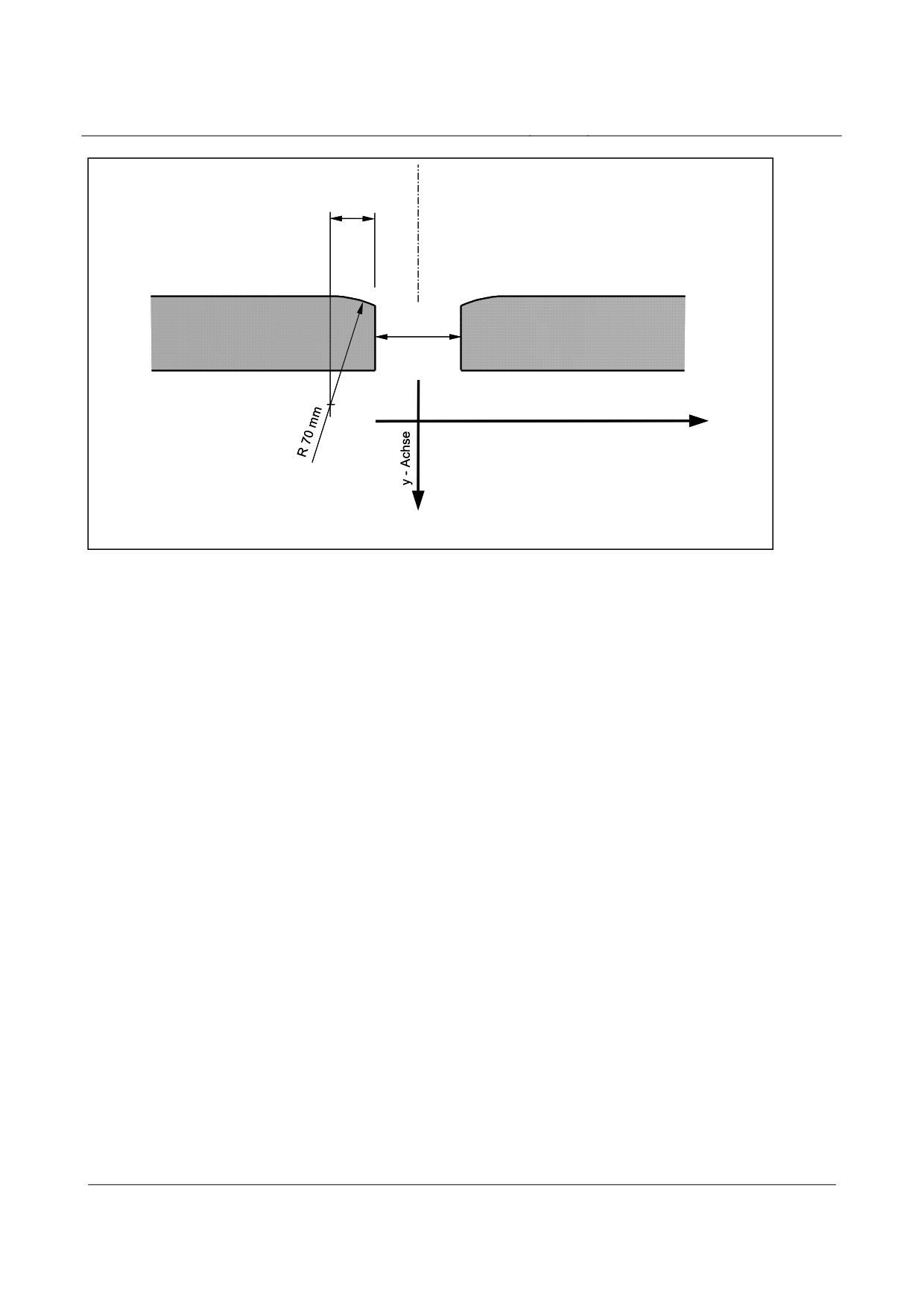
The joints in the lateral guide rail level shall be designed in accordance with fig. 215.
Title
High-speed Maglev Systems - Design principles
Guideway - Part III: Geometry
Doc. no.:
41727
Version White Paper Issue date
15.02.2007
Page 47
High-speed maglev systems
Maglev Technical Committee
Design principles
Guideway
22 mm
Spalt ∆X
x - Achse
Fig. 215:
Surface design of the lateral guide rail level at the girder joint or in the event of interruptions
[Key to diagram:
Spalt = opening
x-Achse = x-axis
y-Achse = y-axis]
Positional deviation of the lateral guide rail level in the y direction
Theoretical position
The theoretical position of the two lateral guide rail levels is specified by the routing. Long-wave
deviation tolerance zone progression relates to these theoretical positions. The following data per-
taining to long- and short-wave deviation relates to every individual lateral guide rail level. The
compulsorily existing dependency of the actual positions of the two long-wave deviations is not
taken into consideration with a view to observing the guideway gauge tolerance.
Possible deformation as a result of the vehicle load impact and temperature differences in the
guideway are disregarded when determining the theoretical position of the lateral guide rail level.
Long-wave deviation in the lateral guide rail level
Long-wave deviation tolerance zone progression is described as follows depending on the design
of the girder:
Simple beams
x
<x
<x
∆
y
as per equation 18 *
Trägeranfang
i
Trägerende
i,Lw
* L
≤12384
max∆y
=1,0
Lw
[mm]
L
>12384
max∆y
=
L * 2,0/24768
Lw
Title
High-speed Maglev Systems - Design principles
Guideway - Part III: Geometry
Doc. no.:
41727
Version White Paper Issue date
15.02.2007
Page 48
High-speed maglev systems
Maglev Technical Committee
Design principles
Guideway
Two-span beams
x
≤x
≤L
∆
y
as per equation 19 *
Trägeranfang
i
1
i,Lw
L
≤x
≤x
∆
y
as per equation
2
i
Trägerende
i,Lw
19 **
* L
≤12384
max∆y
=1,0
1
Lw
[mm]
L
>12384
max∆y
=
L
* 2,0 / 24768
1
Lw
1
** L
≤12384
max∆y
=
1,0
1
Lw
[mm]
L
>12384
max∆y
=
L
* 2,0 / 24768
1
Lw
2
Multiple span girders (gauge change devices)
x
≤x
≤L
∆
y
⇒ follows the mathematical description of the elastic
Trägeranfang
i
1
i,Lw
line *
L
<
x
<
∆
y
⇒ follows the mathematical description of the elastic
2
i
L
n 1
i,Lw
line *
L
≤x
≤x
∆
y
⇒ follows the mathematical description of the elastic
n
i
Trägerende
i,Lw
line *
* L
≤12384
max∆y
=
1,0
i
Lw
[mm]
L
>12384
max∆y
=
L
* 2,0 / 24768
i
Lw
i
i = 1,...n
see Chapter 6.6.2;
Short-wave deviation in relation to the actual location of the lateral guide rail level (long-
wave deviation), tolerances at the girder joint
Short-wave deviation tolerance zone progression relative to the actual progression of the long-
wave deviation is described by the following basic data in a standard manner for the simple beam
and multiple span girder:
x
;
x
∆y=0
Trägeranfang
Trägerende
x
<
x
<
;
Trägeranfang
i
x0+n*1032
x
<
x
<
x
n =1,2...*
∆y
≤±2mm
L-n*1032
i
Trägerende
i
x
<
x
<
x
∆y=±2mm
0+n*1032
i
L−n*1032
* n shall be stipulated in observance of the maximum permitted gradient-altering criterion
Title
High-speed Maglev Systems - Design principles
Guideway - Part III: Geometry
Doc. no.:
41727
Version White Paper Issue date
15.02.2007
Page 49
High-speed maglev systems
Maglev Technical Committee
Design principles
Guideway
Within the short-wave deviation tolerance zone, the following proximity relation must be observed
in the lateral guide rail level:
NGK
≤ 2,0mm
SFE
For determining the tolerance zone progression of the lateral guide rail level at the beginning and
end of the girder (girder transition), a gradient-altering criterion, relative to the theoretical position,
of
NGK
≤ 1,0mm
SFE,Anfang;Ende
shall be calculated.
The permitted limit values set out in the Guideway design principles for high-speed maglev systems
- Part II: Dimensioning, must be observed in this regard.
As regards the gradient-altering criterion to be defined at these points for inspection and acceptance
measurements, the measurement conditions must be specified.
Permitted lateral guide rail level displacements / tilting
The following tolerances relate to the measurement points according to fig. 185 and the stipulations
concerning the choice of the pertinent x coordinates.
The tolerances listed below are the same for all types of guideway.
-
Displacements:
within the girder
∆y
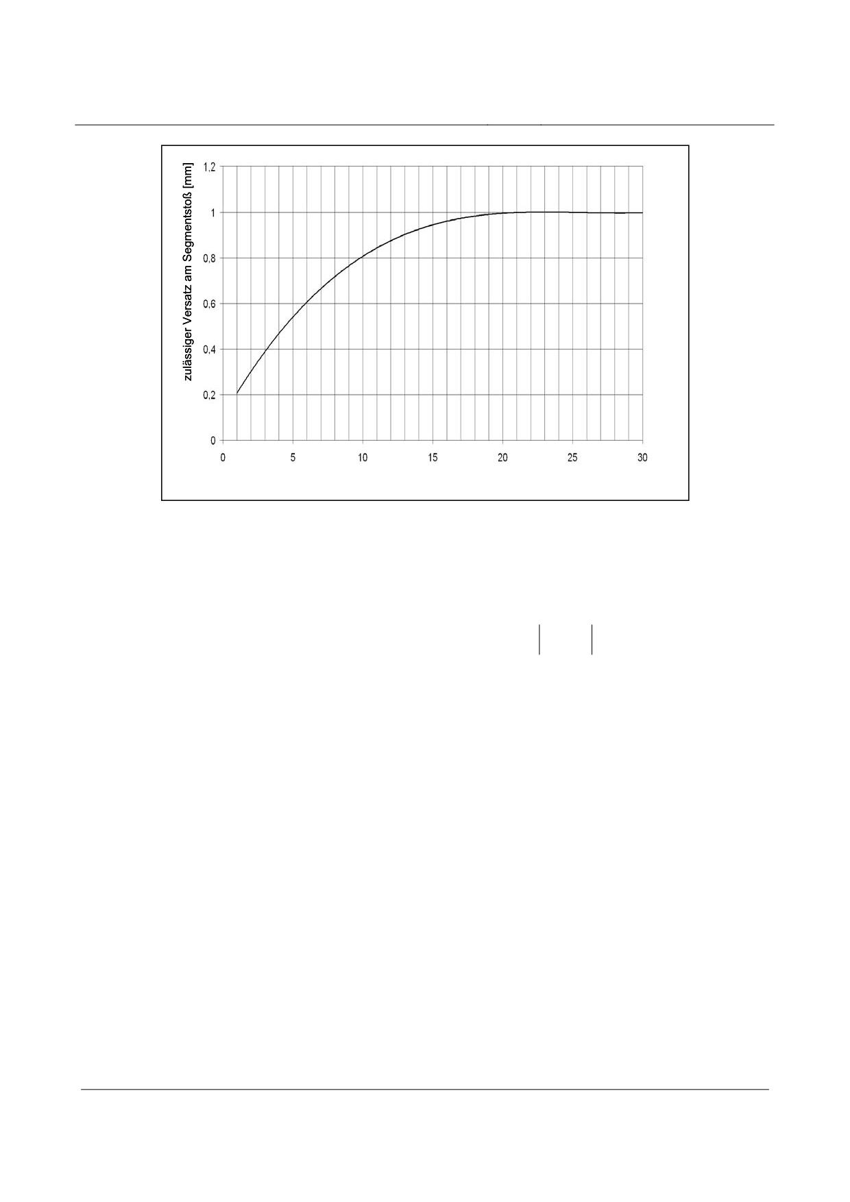
= 0,6mm *
i
max
* the assumed segment length in this regard is 6 m,
With different lengths, the value shall be taken from the diagram below:
Title
High-speed Maglev Systems - Design principles
Guideway - Part III: Geometry
Doc. no.:
41727
Version White Paper Issue date
15.02.2007
Page 50
High-speed maglev systems
Maglev Technical Committee
Design principles
Guideway
Segmentlänge [m]
Fig. 216:
Permitted displacements in the lateral guide rail level within a support structure depending on the segment
lengths of the lateral guides
[Key to diagram:
zulässiger Versatz am Segmentstoß = permitted displacement at the segment joint
Segmentlänge = segment length]
at the girder joint
∆y
= 1,0mm
i
max
Displacement at the girder joint is adjusted following precise positioning of the girder and
presupposes a guideway gauge tolerance of ± 1mm (see point 6.7.2.3).
-
tilting (relative to the measurement point):
within the girder
∆α
=±arctan(1,0mm/155mm)
SFE
max
inside, at lateral guide rail level joints
∆α
= ±arctan(0,7mm/155mm)
SFE
max
at the girder joint
∆α
= ±arctan(0,5mm/155mm)
SFE
max
Permitted guideway gauge tolerance
Changes in the guideway gauge as a result of a uniform change in the girder temperature in relation
to the reference temperature (“temperature at the time of installation”) must be considered over and
above the permitted tolerance.
The guideway gauge tolerance for all types of guideway is as follows:
within the support structure
∆S=±2mm
Title
High-speed Maglev Systems - Design principles
Guideway - Part III: Geometry
Doc. no.:
41727
Version White Paper Issue date
15.02.2007
Page 51
High-speed maglev systems
Maglev Technical Committee
Design principles
Guideway
at the beginning/end of the support structure
∆S
= ±1mm
Anfang;Ende
Title
High-speed Maglev Systems - Design principles
Guideway - Part III: Geometry
Doc. no.:
41727
Version White Paper Issue date
15.02.2007
Page 52

High-speed maglev systems
Maglev Technical Committee
Design principles
Guideway
Slider level tolerances and positional deviations
The slider level becomes the functional area when a maglev train sets off.
In terms of considerations regarding tolerance and positional deviation, its relationship with the
actual progression of the stator level is given by means of the hover clearance. In other words, the
actual long-wave deviation in the stator level shall be taken into consideration when determining the
theoretical progression of the slider level (see fig. 219).
If a slider level reference to the theoretical position of the stator level is necessary for production-
related reasons, when stipulating the slider level tolerance zone, inter alia, the two extremes in terms
of long-wave stator level deviation must be taken into account.
The tolerance in terms of the hover clearance and data concerning the gradient-altering criterion
limit values for the slider level must also be observed.
The mutual influence exerted by the individual tolerances and positional deviations in the z coordi-
nates is presented in the following overview (fig. 217).
The x and y coordinate correlations were not presented given their secondary importance.
Lage der GE im MKS
Montagetoleranz des FW-Trägers bei der Ausrichtung zu einem bereits
Montagetoleranz des FW-Trägers, freies Ausrichten im MKS
montierten FW-Träger
Z-Koordinaten der GLE im Trägerkoordinatensystem (bei der Fertigung)
Abweichung der rechten zur linken GE eines
kurzwellige Abweichung GE
Trägers in Z-Richtung (Querneigungstoleranz)
zulässige Verkippung der GE um ihre
langwellige Abweichung der SE + Zangenmaß
X-Achse
Neigungsänderungskriterium innerhalb der
GE
Ausbildung der GE am Trägeranfang
und -ende
Fig. 217:
Slider level tolerances and positional deviations in the z direction and their mutual dependence
[Key to diagram:
Lage der GE im MKS = position of the slider level in the maglev train coordinate system
Montagetoleranz des FW-Trägers bei der Ausrichtung zu einem bereits montierten FW-Träger = assembly
tolerance of the guideway girder in the case of alignment with a guideway girder which has already been
installed
Montagetoleranz des FW-Trägers, freies Ausrichten im MKS = assembly tolerance of the guideway girder,
free alignment in the maglev train coordinate system
Z-Koordinaten der GLE im Trägerkoordinatensystem (bei der Fertigung) = z-coordinates of the slider level in
the girder coordinate system (during production)
Abweichung der rechten zur linken GE eines Trägers in Z-Richtung (Querneigungstoleranz) = deviation bet-
ween the right and left slider levels of a girder in the z direction (lateral incline tolerance)
kurzwellige Abweichung GE = short-wave deviation in the slider level
zulässige Verkippung der GE um ihre X-Achse = permitted tilting of the slider level about its x-axis
langwellige Abweichung der SE + Zangenmaß = long-wave deviation in the stator level + the hover clearan-
ce
Neigungsänderungskriterium innerhalb der GE = gradient-altering criterion within the slider level
Title
High-speed Maglev Systems - Design principles
Guideway - Part III: Geometry
Doc. no.:
41727
Version White Paper Issue date
15.02.2007
Page 53
High-speed maglev systems
Maglev Technical Committee
Design principles
Guideway
Ausbildung der GE am Trägeranfang und -ende = slider level formation at the beginning and end of the gir-
der]
Title
High-speed Maglev Systems - Design principles
Guideway - Part III: Geometry
Doc. no.:
41727
Version White Paper Issue date
15.02.2007
Page 54
High-speed maglev systems
Maglev Technical Committee
Design principles
Guideway
Permitted slider level tolerances in the x direction
Permitted gap in the x direction within the sliding rail
The maximum permitted gap widths depending on their position in the guideway are defined in the
Principles concerning the overall system design of high-speed maglev systems.
In the case of a one-piece slider level design over the entire length of the support structure, its heat
expansion as set out in the Guideway design principles for high-speed maglev systems - Part II:
Dimensioning, must be taken into consideration relative to the system axes at the beginning and end
of the girder.
To determine the minimum gap, i.e. the distance from the beginning and end of the girder to the
system axis, in the case of support structures, the arrangement of the fixed and movable bearings, as
well as the permitted support deformation as per the Principles concerning the overall system design
of high-speed maglev systems, must be taken into consideration.
The following standard values are specified:
The gap between the start or end of the girder and the system axes:
Support structure (12 m ≤ system length ≤ 25 m)
∆x
= 20mm
A,E
Guideway plates (system length ≤ 6 m)
∆x
=10mm
A,E
The aim will be to achieve uniform girder joints at the reference temperature.
In the case of interruptions to the slider level which are the result of its design (e.g. with a modular
design), the positional stability and form deviation of the slider level elements must be taken into
consideration when determining the theoretical gap widths in the support structure.
In the case of points, the minimum gap which is required within the point between the slider level
elements is determined in accordance with equation 22.
The number of gaps in the slider level is to be kept to a minimum (6.7.3.3.4).
A collision between like, adjacent functional level elements must be avoided.
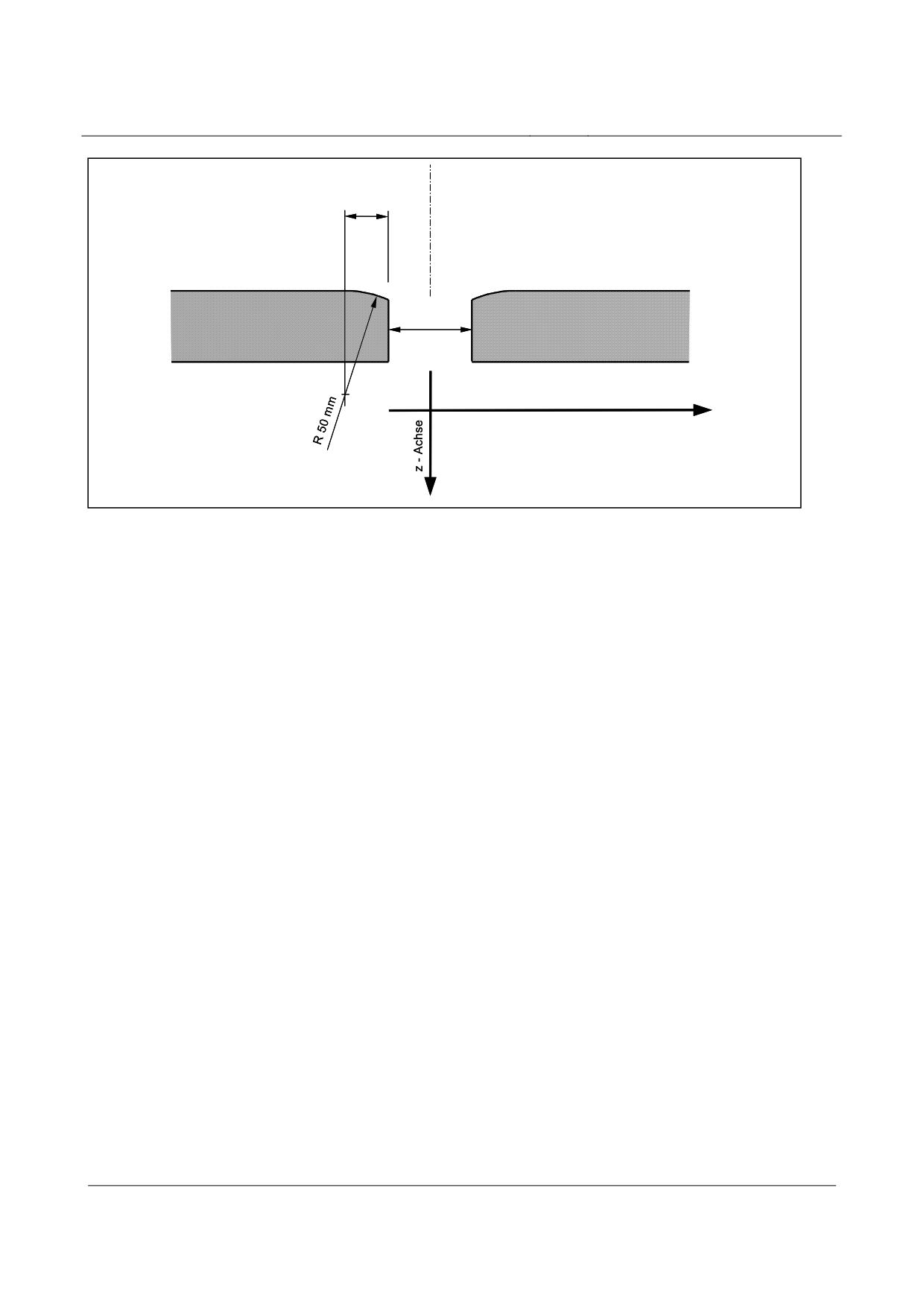
The joints in the slider level shall be designed in accordance with fig. 218.
Title
High-speed Maglev Systems - Design principles
Guideway - Part III: Geometry
Doc. no.:
41727
Version White Paper Issue date
15.02.2007
Page 55
High-speed maglev systems
Maglev Technical Committee
Design principles
Guideway
22 mm
Spalt
∆X
x - Achse
Fig. 218:
Surface design of the slider level at the girder joint or in the event of interruptions
[Key to diagram:
Spalt = opening
x-Achse = x-axis
z-Achse = z-axis]
Permitted slider level tolerances in the Y direction
Relative to the centre axis of the longitudinal stator, the following uniform tolerance applies to all
types of guideway from the beginning of the support structure to the end:
∆y = ±16mm
Permitted slider level tolerances in the z direction
Theoretical position
The theoretical position of the slider level is stipulated in relation to the stator level by means of the
hover clearance (-398 mm to the actual position of the stator level base).
As a basis for the actual position in this regard, the long-wave deviation progression, which is de-
termined using the continuous stator level measured values, is used (see fig. 219).
Title
High-speed Maglev Systems - Design principles
Guideway - Part III: Geometry
Doc. no.:
41727
Version White Paper Issue date
15.02.2007
Page 56
High-speed maglev systems
Maglev Technical Committee
Design principles
Guideway
Obergrenze der kurzwelligen Abweichung
∆zi,Kw
projizierte Ist - Lage der
langwelligen Abweichung der SE
Untergrenze der kurzwelligen Abweichung
Zangenmaß 398 mm
Ist - Lage der
langwelligen Abweichung der SE
x-Achse
LSt/ 2
LSt
L
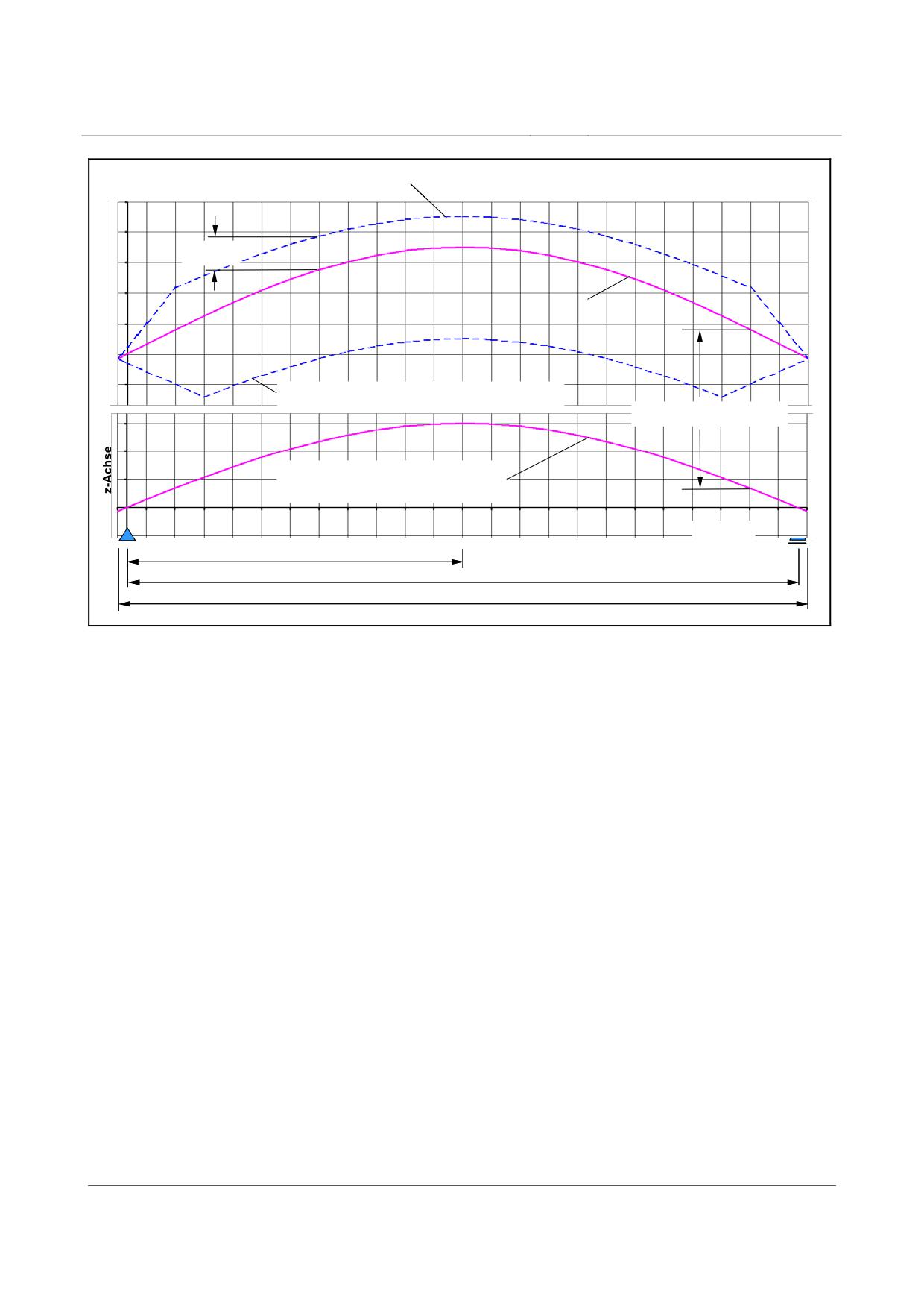
Fig. 219:
The progression and position of the slider level’s short-wave deviation using the example of a simple beam
with precurvature
[Key to diagram:
Obergrenze der kurzwelligen Abweichung = upper limit for short-wave deviation
projizierte Ist-Lage der langwelligen Abweichung der SE = projected actual position of the long-wave deviati-
on in the stator level
Untergrenze der kurzwelligen Abweichung = lower limit for the short-wave deviation
Zangenmaß = hover clearance
Ist-Lage der langwelligen Abweichung der SE = actual position of the long-wave deviation in the stator level
x-Achse = x-axis
z-Achse = z-axis]
The tolerances given below are valid for each slider level (right and left sides). A direct dependence
on one another of the theoretical positions of the two slider levels is not envisaged.
Long-wave deviation in the slider level
The slider level tolerance range is determined by the actual long-wave progression of the stator le-
vel. For this purpose, the latter is displaced by the hover clearance.
A separate examination is dispensed with (see fig. 219).
Title
High-speed Maglev Systems - Design principles
Guideway - Part III: Geometry
Doc. no.:
41727
Version White Paper Issue date
15.02.2007
Page 57
High-speed maglev systems
Maglev Technical Committee
Design principles
Guideway
Short-wave deviation in the slider level
The actual long-wave progression of the stator level is shifted upwards by the amount of the hover
clearance.
The upper and lower limit range is superimposed on this, which is described in a uniform manner
for all guideway types by the following basic data:
x
;
x
∆z
=±0,4mm
0
L
i
x
<
x
<
x
;
x
<
x
<
x
n =1,2...*
- 3mm ≤ ∆ z
≤+5mm
0
i
0+n
L-n
i
L
i
x
<
x
<
x
- 3mm = ∆ z
=+5mm
>n
i
<
(
L-n
)
i
* n shall be stipulated in observance of the maximum permitted gradient-altering criterion
At each point, the criterion concerned with the gradient-altering criterion must also be observed (see 6.7.3.4).
Within the short-wave deviation tolerance zone, the following proximity relation must be observed
in the slider level:
NGK
≤
3,0mm
GE
For determining the tolerance range progression of the slider level at the beginning and end of the
girder (girder transition), a gradient-altering criterion, relative to the theoretical position of the sta-
tor level, of
NGK
≤1,5mm
GE,Anfang;Ende
shall be applied.
The permitted limit values set out in the Guideway design principles for high-speed maglev sys-
tems - Part II: Dimensioning, must be observed in this regard.
Title
High-speed Maglev Systems - Design principles
Guideway - Part III: Geometry
Doc. no.:
41727
Version White Paper Issue date
15.02.2007
Page 58
High-speed maglev systems
Maglev Technical Committee
Design principles
Guideway
Permitted slider level displacements / tilting
The following tolerances relate to the measurement points according to fig. 185 and the stipulations
concerning the choice of the pertinent x coordinates.
The tolerances listed below are the same for all types of guideway.
• Displacements:
within the girder
∆z
= 0,2mm *
i
max
* Depending on the frequency with which they occur, tolerances may be exceeded in conti-
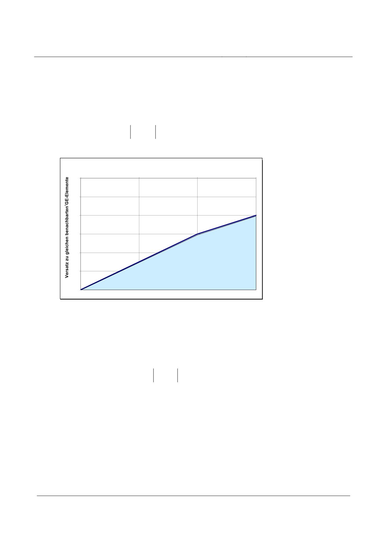
guous guideway sections under the conditions presented in fig. 220:
Anzahl aller GE-Unterbrechungen in den Fahrwegträgern
0
10
20
30
0
0,1
0,2
0,3
0,4
0,5
0,6
Fig. 220:
Permitted displacements in the slider level within the support structure depending on their extent and the
frequency with which they occur
[Key to diagram:
Anzahl aller GE-Unterbrechungen in den Fahrwegträgern = number of all the slider level interruptions in the
support structures
Versatz zu gleichen benachbarten GE-Elemente = displacement in relation to similar adjacent slider level
elements]
at the girder joint
∆z
= 0,6mm
i
max
The displacement at the girder joint comprises the tolerance width of the short-wave deviati-
on for the slider level at the girder joint, the portion of tolerance relating to the hover clea-
rance (Chapter 6.7.3.4) and the assembly tolerance.
• tilting (relative to the measurement point in the centre axis of the longitudinal stator):
∆α
=±arctan
(
0,5mm / 75mm
)
GE
max
Title
High-speed Maglev Systems - Design principles
Guideway - Part III: Geometry
Doc. no.:
41727
Version White Paper Issue date
15.02.2007
Page 59
High-speed maglev systems
Maglev Technical Committee
Design principles
Guideway
Hover clearance
The permitted hover clearance is established from a calculation of the permitted short-wave toleran-
ces regarding the stator and slider levels (see Chapter 6.7.3.3.3 and fig. 219).
The following dimensions may be used as standard values for a punctual, geometric inspection u-
sing sample points without taking into account the long- and short-wave tolerances:
Nominal size:
398 mm
Standard value within the girder:
from 393 mm to 401 mm
Standard value at the beginning/end of the girder: from 397.6 mm to 398.4 mm
Title
High-speed Maglev Systems - Design principles
Guideway - Part III: Geometry
Doc. no.:
41727
Version White Paper Issue date
15.02.2007
Page 60
High-speed maglev systems
Maglev Technical Committee
Design principles
Guideway
Guideway assembly
The tolerances relating to precise positioning are specified in the Guideway design principles for
high-speed maglev systems - Part IV: Surveying.
Title
High-speed Maglev Systems - Design principles
Guideway - Part III: Geometry
Doc. no.:
41727
Version White Paper Issue date
15.02.2007
Page 61
High-speed maglev systems
Maglev Technical Committee
Design principles
Guideway
Geometric requirements pertaining to the calibrated guideway
Irrespective of the data provided previously, more stringent requirements are laid down in relation
to the geometry of calibrated girders (guideway section within the central maintenance depot, as-
sists in calibrating the maglev train). In this regard, the tolerances mentioned below in relation to
the load-free girder are regarded as framework conditions for the time being:
As regards the stator level:
∆zmax = ±1 mm
where
L
≥18m
│∆zi│≤ ∆zmax
Sys
where
L
<18m
0,1mm <
∆z
<
∆z
*L
/18m
Sys
i
max
Sys
As regards the lateral guide level:
∆ymax = ±1 mm
where
L
≥18m
│∆yi│≤ ∆ymax
Sys
where
L
<18m
0,1mm <
∆y
<
∆y
*L
/18m
Sys
i
max
Sys
As regards the guideway gauge:
∆Smax = ±0,5 mm
where
L
≥18m
│∆Si│≤ ∆Smax
Sys
where
L
<18m
0,1mm <
∆S
<
∆S
*L
/18m
Sys
i
max
Sys
As regards the hover clearance:
∆Zmax = ±1 mm
where
L
≥18m
│∆Zi│≤ ∆Zmax
Sys
where
L
<18m
0,1mm <
∆Z
<
∆Z
*L
/18m
Sys
i
max
Sys
Title
High-speed Maglev Systems - Design principles
Guideway - Part III: Geometry
Doc. no.:
41727
Version White Paper Issue date
15.02.2007
Page 62
High-speed maglev systems
Maglev Technical Committee
Design principles
Guideway
In addition, the following requirements pertaining to the rigidity of the girder apply:
Where the girder is subjected to a load comprising the weight of the vehicle (vehicle fully equip-
ped), the following applies to the difference between the girder under load and the load-free girder
in the z direction:
∆zmax = 1 mm
where
L
≥18m
│∆zi│≤ ∆zmax
Sys
where
L
<18m
0,1mm <
∆z
<
∆z
*L
/18m
Sys
i
max
Sys
With a lateral load of 0.3 g:
∆ymax = 1 mm
where
L
≥18m
│∆yi│≤ ∆ymax
Sys
where
L
<18m
0,1mm <
∆y
<
∆y
*L
/18m
Sys
i
max
Sys
Title
High-speed Maglev Systems - Design principles
Guideway - Part III: Geometry
Doc. no.:
41727
Version White Paper Issue date
15.02.2007
Page 63
High-speed maglev systems
Maglev Technical Committee
Design principles
Guideway
Positional requirements relating to guideway ancillary devices and
equipment items
Position of the motor winding
The clearance required for motor winding installation is defined in the Principles concerning the
overall system design of high-speed maglev systems.
The motor winding shall be positioned such that the clearance is observed under all operating con-
ditions.
The arrangement and location of the individual phases in relation to each other are defined in the
Principles concerning the overall system design of high-speed maglev systems.
The distances between the meander of the motor winding and their x grids are determined by the
chosen arrangement of the stator plates in the x direction. The basic meander grid is 258 mm.
Location of the positional reference guide rail
The clearance in the y and z directions which is required for installation of the positional reference
guide rail is defined in the Principles concerning the overall system design of high-speed maglev
systems.
The arrangement in the x direction is based on the position of the girder reference locations which
is dependent on the actuation period.
Positional reference guide rails are secured to the guideway at the reference locations by means of
special supports. The design of the supports and their attachment is defined in relation to the speci-
fic project.
The guideway reference locations are laid down in relation to the project with the drive design and
the operational process control system.
Location of the external inductive power sup-
ply guideway-side assemblies
Location of the conductor rail guideway-side assemblies
The location of the conductor rails is laid down for individual sections of guideway in relation to
the specific project.
The clearance in the y and z directions which is required for installation of the conductor rails is
defined in the Principles concerning the overall system design of high-speed maglev systems.
The location, in principle, of the conductor rail supports is laid down in the Guideway design prin-
ciples for high-speed maglev systems - Part I: Principle requirements.
Title
High-speed Maglev Systems - Design principles
Guideway - Part III: Geometry
Doc. no.:
41727
Version White Paper Issue date
15.02.2007
Page 64
High-speed maglev systems
Maglev Technical Committee
Design principles
Guideway
Location of the inductive power transmission guideway-side
assemblies
The inductive power transmission is currently still at the development stage. The requirements per-
taining to this assembly are therefore added.
Temporarily, the project-independent requirements relating to “other guideway equipment as-
semblies” and project-specific stipulations apply.
Title
High-speed Maglev Systems - Design principles
Guideway - Part III: Geometry
Doc. no.:
41727
Version White Paper Issue date
15.02.2007
Page 65
High-speed maglev systems
Maglev Technical Committee
Design principles
Guideway
Proofs
Building components and assemblies shall be measured within the framework of quality assurance
following the production steps and variance comparisons carried out and documented.
The production documentation shall specify the date and the dimensions to be checked. The tole-
rance to be considered at the time of testing shall be determined in accordance with the overall tole-
rance assessment.
The fundamental requirements pertaining to quality assurance, building and acceptance shall be
taken from the Guideway design principles for high-speed maglev systems - Part I: Principle requi-
rements.
The approved measuring instruments and methods which are suitable for acceptance measurements
shall be applied to prove observance of the tolerances in accordance with these design principles.
Title
High-speed Maglev Systems - Design principles
Guideway - Part III: Geometry
Doc. no.:
41727
Version White Paper Issue date
15.02.2007
Page 66
High-speed maglev systems
Maglev Technical Committee
Design principles
Guideway
Annex III-A
Stator plate attachment (support structure side)
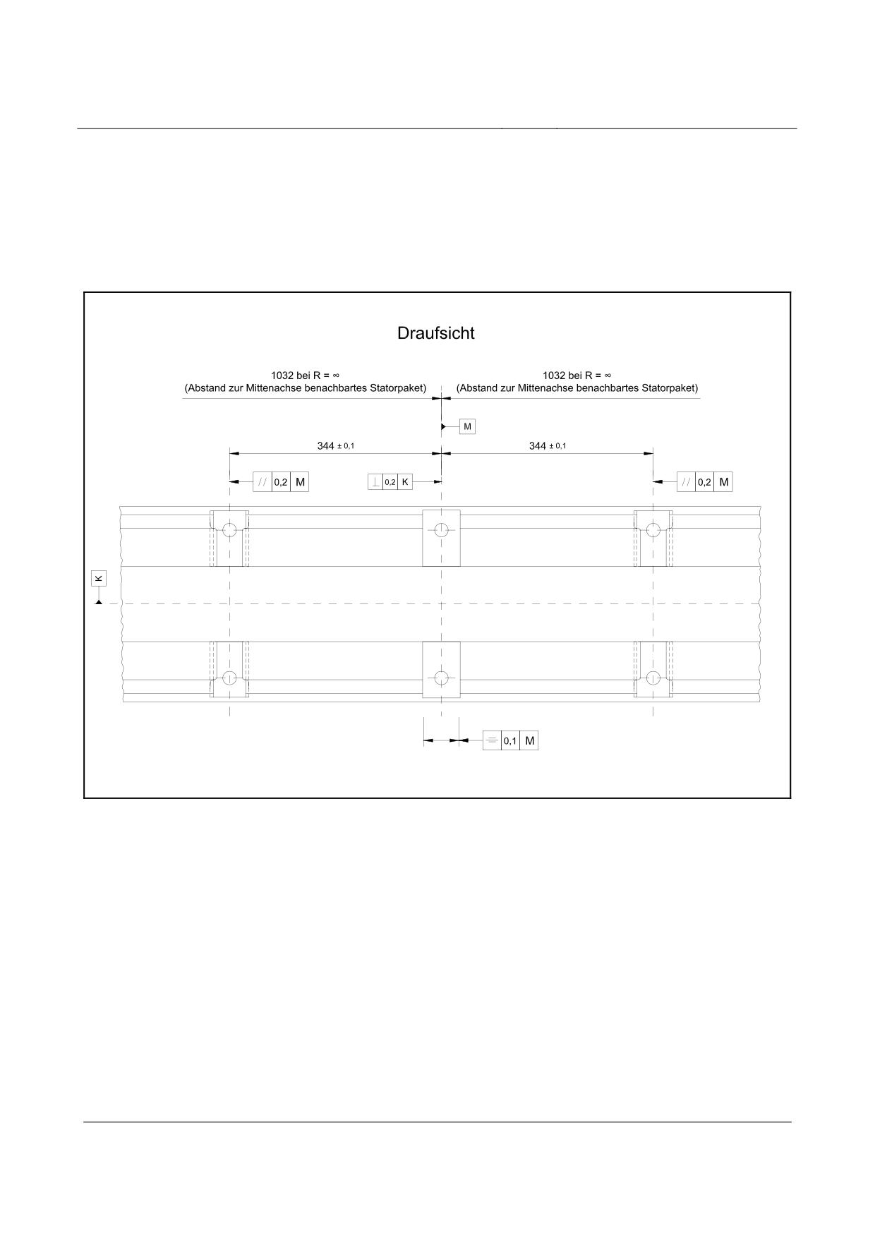
The diagrams below (figs, 221, 222, 223 and 224) are examples of a solution for incorporating the
stator plates along a continuous stator girder boom.
As an alternative, so called inserts are possible. The specified dimensions and tolerances apply to
both variants.
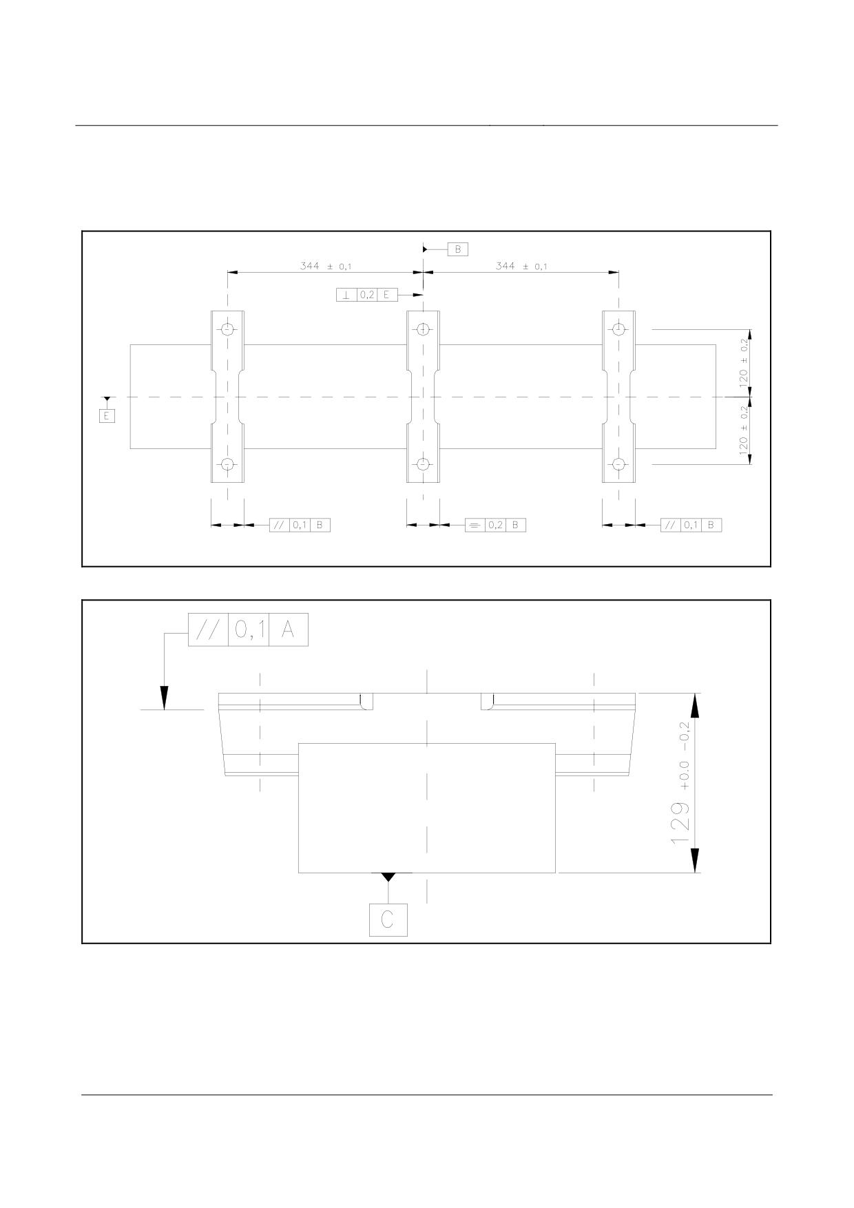
Fig. 221:
Dimensions and tolerances for designing stator plate incorporation in a steel construction (top view)
[Key to diagram:
Draufsicht = top view
Abstand zur Mittenachse benachbartes Statorpaket = distance to the centre axis of the adjacent stator plate]
Title
High-speed Maglev Systems - Design principles
Guideway - Part III: Geometry
Doc. no.:
41727
Version White Paper Issue date
15.02.2007
Page 67
High-speed maglev systems
Maglev Technical Committee
Design principles
Guideway
Fig. 222:
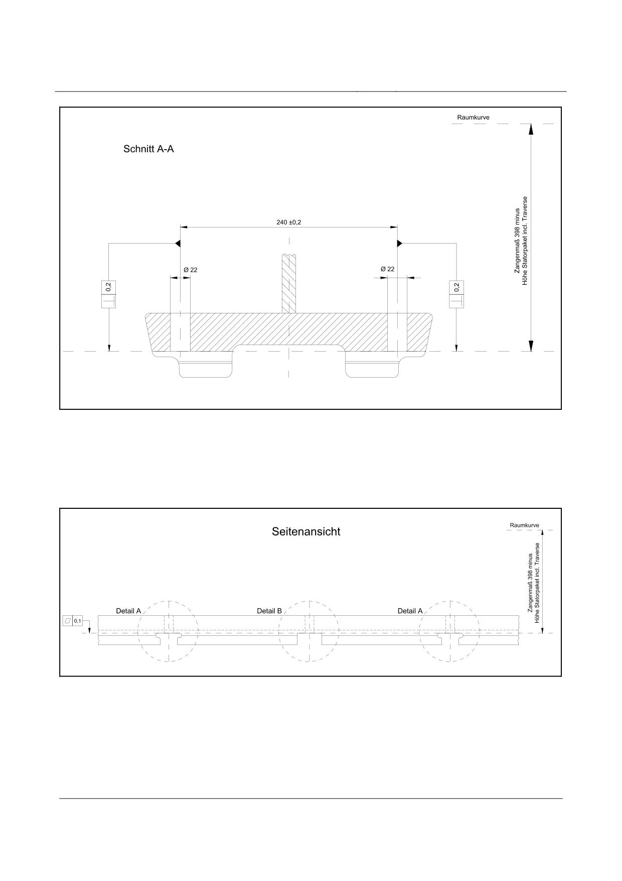
Dimensions and tolerances for designing stator plate incorporation in a steel construction (cross-section)
[Key to diagram:
Raumkurve = space curve
Schnitt A-A = section A-A
Zangenmaß 398 minus Höhe Statorpaket incl. Traverse = hover clearance 398, minus the height of the sta-
tor plate, including the tie-bar]
Fig. 223:
Dimensions and tolerances for designing stator plate incorporation in a steel construction (side view)
[Key to diagram:
Raumkurve = space curve
Seitenansicht = side view
Zangenmaß 398 minus Höhe Statorpaket incl. Traverse = hover clearance 398, minus the height of the sta-
tor plate, including the tie-bar
Detail = detail]
Title
High-speed Maglev Systems - Design principles
Guideway - Part III: Geometry
Doc. no.:
41727
Version White Paper Issue date
15.02.2007
Page 68
High-speed maglev systems
Maglev Technical Committee
Design principles
Guideway
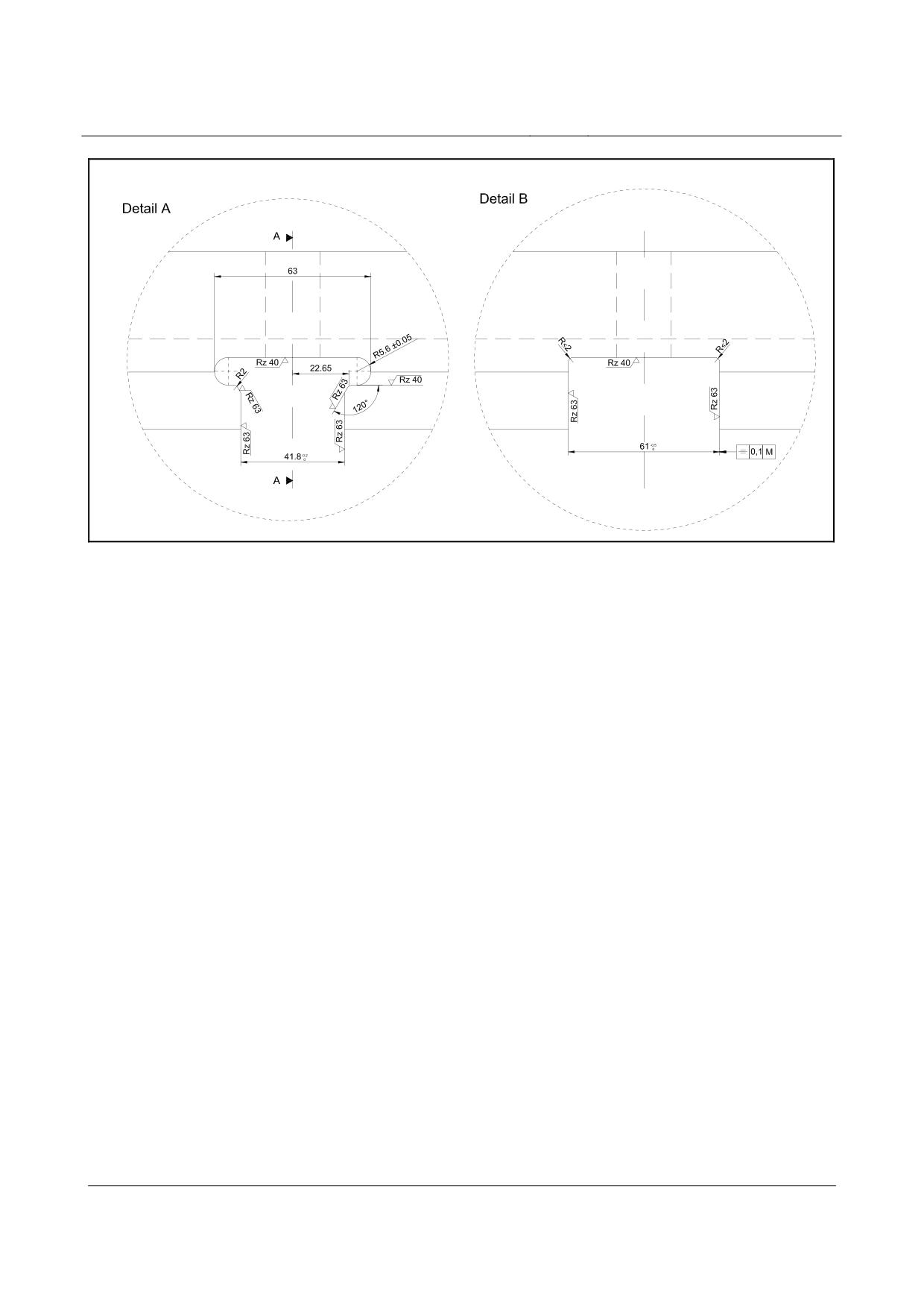
Fig. 224:
Dimensions and tolerances for designing stator plate incorporation in a steel construction (details A and B)
[Key to diagram:
Detail = detail]
Title
High-speed Maglev Systems - Design principles
Guideway - Part III: Geometry
Doc. no.:
41727
Version White Paper Issue date
15.02.2007
Page 69
High-speed maglev systems
Maglev Technical Committee
Design principles
Guideway
Annex III-B
Stator plate fixing axes
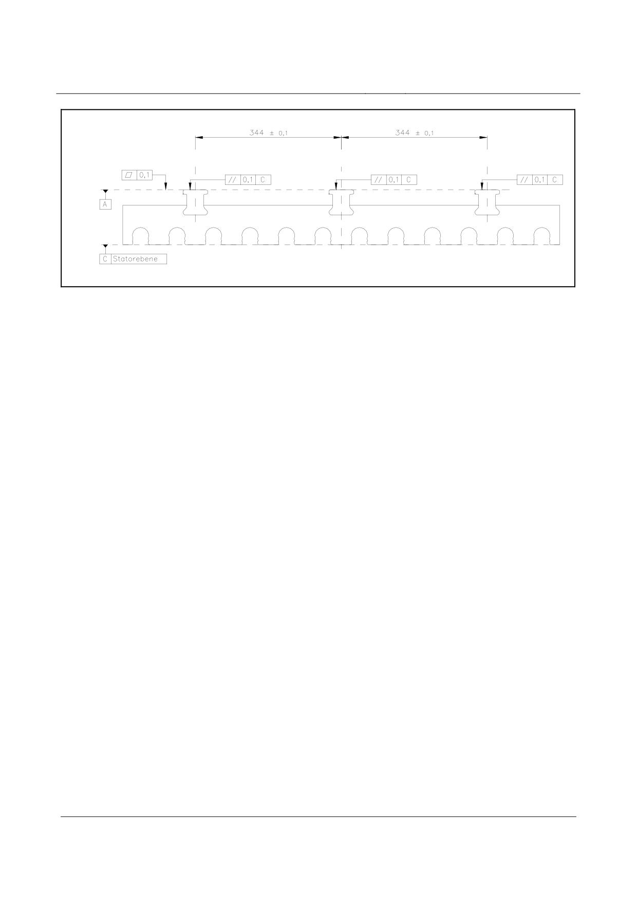
The diagrams below (figs. 225, 226 and 227) are examples of stator plate fixing axes.
Fig. 225:
Stator plate fixing axes (top view)
Fig. 226:
Stator plate fixing axes (cross-section)
Title
High-speed Maglev Systems - Design principles
Guideway - Part III: Geometry
Doc. no.:
41727
Version White Paper Issue date
15.02.2007
Page 70
High-speed maglev systems
Maglev Technical Committee
Design principles
Guideway
Fig. 227:
Stator plate fixing axes (side view)
Title
High-speed Maglev Systems - Design principles
Guideway - Part III: Geometry
Doc. no.:
41727
Version White Paper Issue date
15.02.2007
Page 71
High-speed Maglev system
Maglev Technical Committee
Design principles
Guideway
High-speed maglev systems
Design principles
Guideway
Part IV
Routing
The author has copyright over this document and all of its annexes.
All rights reserved
Title
High-speed Maglev system, design principles
Guideway, Part IV, Routing
Doc. No.:
60640
Version White pa-
Issue date
15.02.2007
Page 1
per
High-speed Maglev system
Maglev Technical Committee
Design principles
Guideway
Distributor
This document was released for publication by the Guideway Technical Committee.
Title
High-speed Maglev system, design principles
Guideway, Part IV, Routing
Doc. No.:
60640
Version White pa-
Issue date
15.02.2007
Page 2
per
High-speed Maglev system
Maglev Technical Committee
Design principles
Guideway
Revision history
Date of release: 15.02.2007, White Paper published by the Guideway Technical Committee
Title
High-speed Maglev system, design principles
Guideway, Part IV, Routing
Doc. No.:
60640
Version White pa-
Issue date
15.02.2007
Page 3
per
High-speed Maglev system
Maglev Technical Committee
Design principles
Guideway
Table of contents
List of diagrams
List of Tables
Title
High-speed Maglev system, design principles
Guideway, Part IV, Routing
Doc. No.:
60640
Version White pa-
Issue date
15.02.2007
Page 4
per
High-speed Maglev system
Maglev Technical Committee
Design principles
Guideway
General
Object and area of application
This document sets out in detail the generally applicable technical stipulations regarding the routing
of guideways for high-speed maglev systems.
These design principles apply to a maglev train in accordance with the General Maglev Systems’
Act.
Principles for the design of high-speed maglev
systems
This document is part of the documentation relating to high-speed maglev systems consisting of
several design principles. The document tree is presented in fig. 1 of the Principles concerning the
overall system design of high-speed maglev systems.
The primary overall system design documentation and its annexes apply in a uniform manner to
the documentation as a whole:
• Principles concerning the overall system design of high-speed maglev systems, document
number 50630, and its annexes:
• Annex 1: Abbreviations and definitions, document number 67536 [Principles for the de-
sign of high-speed maglev systems - Abbreviations and definitions]
• Annex 2: Acts, Orders, Standards and Guidelines, document number 67539 [Principles
for the design of high-speed maglev systems - Standards and guidelines]
• Annex 3: Environmental conditions, document number 67285 [Principles for the design
of high-speed maglev systems - The environment]
• Annex 4: Rules for operation (driving and maintenance), document number 69061
[Principles for the design of high-speed maglev systems - Driving and maintenance]
• Annex 5: Sound, document number 72963 [Principles for the design of high-speed
maglev systems - Sound]
Abbreviations and definitions
The abbreviations and definitions specified in the Principles for the design of high-speed maglev
systems - Abbreviations and definitions - apply.
Acts, Orders, Standards and Guidelines
The normative documents listed in the Principles for the design of high-speed maglev systems -
Standards and guidelines, contain stipulations which, by reference to the Principles for the design
of high-speed maglev systems, become part of the same. Later amendments or revisions to these
publications do not apply to dated, normative documents found in the Principles for the design of
high-speed maglev systems - Standards and guidelines. Where references are not dated, the most
recent version of the normative document referred to applies.
Title
High-speed Maglev system, design principles
Guideway, Part IV, Routing
Doc. No.:
60640
Version White pa-
Issue date
15.02.2007
Page 5
per
High-speed Maglev system
Maglev Technical Committee
Design principles
Guideway
The status of the standards and guidelines to be taken into consideration in a maglev train project
must be laid down in a binding manner specific to the project.
Title
High-speed Maglev system, design principles
Guideway, Part IV, Routing
Doc. No.:
60640
Version White pa-
Issue date
15.02.2007
Page 6
per
High-speed Maglev system
Maglev Technical Committee
Design principles
Guideway
Indicating requirements and their binding na-
ture
The provisions pursuant to DIN 820 were essentially applied when preparing this document.
In the chapters following and the annexes to this document,
• requirements are set out in standard type and
• explanatory notes, standard values and examples are set out in italics
(refer to the Guideway design principles for high-speed maglev systems - Part I: Principle require-
ments).
Title
High-speed Maglev system, design principles
Guideway, Part IV, Routing
Doc. No.:
60640
Version White pa-
Issue date
15.02.2007
Page 7
per
High-speed Maglev system
Maglev Technical Committee
Design principles
Guideway
Routing
General principles governing routing
Taking into account the technical options available, the routing should be chosen in such a way
that during operation involving the theoretical path taken as a basis, economically optimum coordi-
nation is achieved between requirements in terms of travel dynamics, travel comfort, building and
repair costs.
The ultimate aim is for the vehicle to be able to travel over long sections at a constant speed.
Other requirements which are relevant from the point of view of routing, for instance, environmental
and sound insulation reasons, networking with other highways, aesthetic points of view and prod-
uct design, may influence the planning of the line’s location and shall be included in relation to the
specific project.
Guideway axis (space curve)
Guideway axes (space curves) consist of the three-dimensional superimposition of the horizontal
and vertical plan alignment.
Guideway axes shall be provided with a clear designation. This should be numerical and comprise
three digits.
In the case of multi-guideways, every guideway axis shall be routed separately.
Chainage
Based on the use of finished parts as a result of their system and design, chainage shall relate to
the spatial termination of the guideway axis (space curve).
Horizontal and vertical plan alignment
Horizontal and vertical plan routing should be effected separately in the first instance.
The space curve established as a result of the superimposition of the horizontal and vertical plan
alignment must fulfil all the requirements contained in this design principle.
Routing of the stretch as a whole shall be examined using the definitive, simulated actual paths to
ensure that it fully satisfies the projected comfort limit values.
Inclusion of the routing design in calculations
Routing design should be carried out on the basis of general pans and gradient diagrams, together
with their image systems.
The geometric and geodetic bases of the general pans and gradient diagrams shall be examined in
terms of their applicability.
Title
High-speed Maglev system, design principles
Guideway, Part IV, Routing
Doc. No.:
60640
Version White pa-
Issue date
15.02.2007
Page 8
per
High-speed Maglev system
Maglev Technical Committee
Design principles
Guideway
In terms of design-related follow-up work (stipulating the division of supports, bridge structures,
points systems) and as regards subsequent staking, the graphic design shall be included in the
maglev train coordinate system as set out in the Guideway design principles for high-speed maglev
systems - Part IV: Surveying, according to location and elevation.
Existing constraining points shall be surveyed, coordinated and taken into consideration in the cal-
culation.
Inclusion in calculations shall be effected in such a way that
• the progression of the line corresponds to the graphic representation given in the design
plans to the standard degree of precision,
• strictly tangential transitions exist along the main points of the line,
• a steady progression exists in the curvature string and cross-fall string (the exception being
the curvature string deflection and vmax < 100 km/h) and
• the three-dimensional x, y and z coordinates of all the main line points are determined using
the corresponding chainages.
The calculations shall identify
• coordinates and elevations to four decimal places (1/10 mm) and
• data concerning angles to five decimal places.
Horizontal plan routing elements
Standard guideway
Horizontal plan routing elements are as follows:
• straight lines (RH = ∞)
• arcs [of a circle] (RH = constant)
• sinusoids (standard scenario, as a transition curve)
• clothoids (special scenario, as a transition curve)
Sinusoids should be used as transition curves.
In the case of sinusoids, curvature, cross-fall, unbalanced lateral acceleration and lateral jolts are
established as a function of time and the distance travelled.
Clothoids in the form of transition curves can be used in the accelerating and braking areas at sta-
tions and in areas where there are no passengers (e.g. IHZ approaches). This only applies to sec-
tions of guideway on which the theoretical path speed does not exceed 100 km/h.
Subsequent use of that part of the guideway with a higher maximum speed (e.g. in the case of a
network expansion and possible through passage at this station) should be assessed.
Title
High-speed Maglev system, design principles
Guideway, Part IV, Routing
Doc. No.:
60640
Version White pa-
Issue date
15.02.2007
Page 9
per
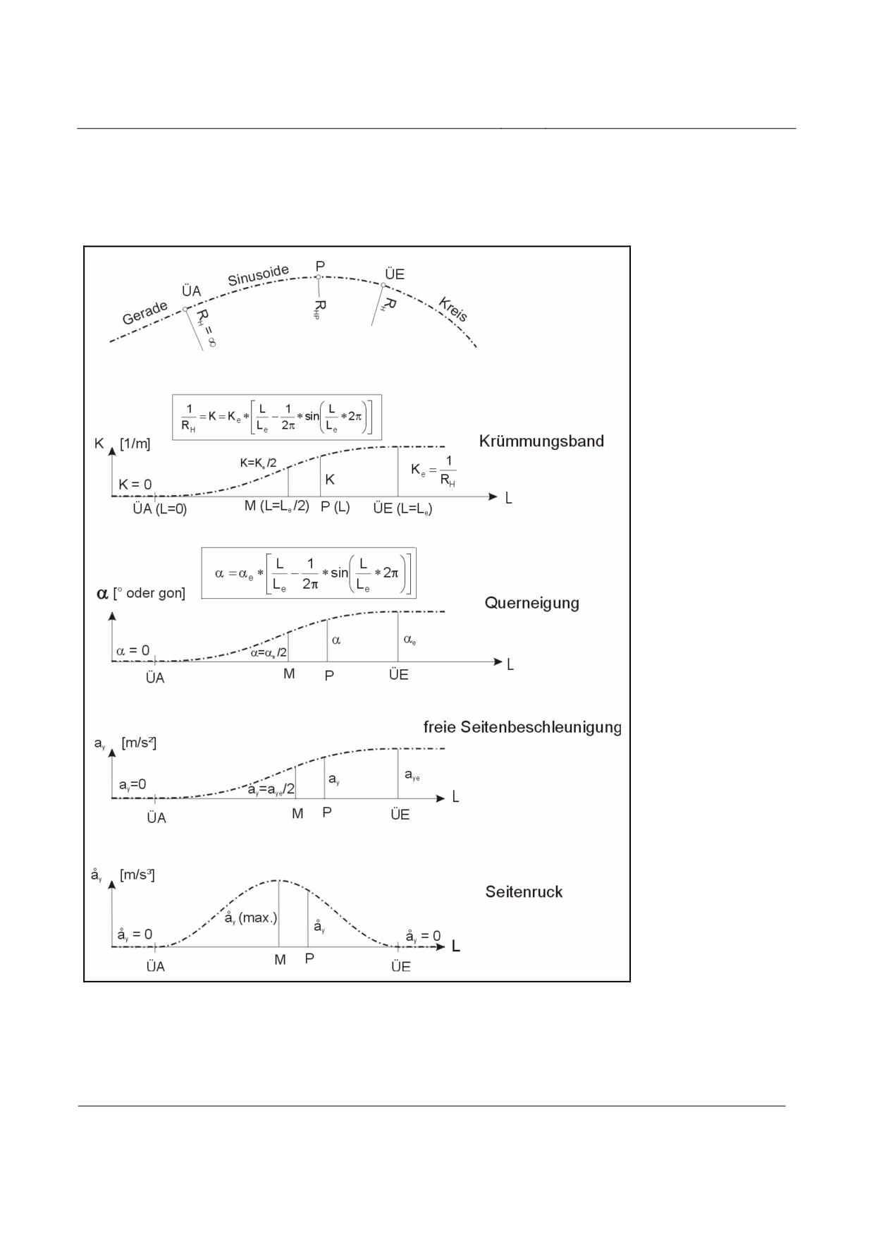
High-speed Maglev system
Maglev Technical Committee
Design principles
Guideway
Cant gradients (S jolts) shall be routed as an element (continuous sinusoids).
The geometric characteristics of the sinusoids and clothoids and those concerning travel dynamics
are presented below in figs. 228 and 229. The calculation of the minimum sinusoid and clothoid
lengths is explained under point 6.2.4.
Fig. 228:
Geometric characteristics of the sinusoids and those concerning travel dynamics
[Key to diagram:
Gerade = straight line
Sinusoide = sinusoid
Kreis = circle
Title
High-speed Maglev system, design principles
Guideway, Part IV, Routing
Doc. No.:
60640
Version White pa-
Issue date
15.02.2007
Page 10
per
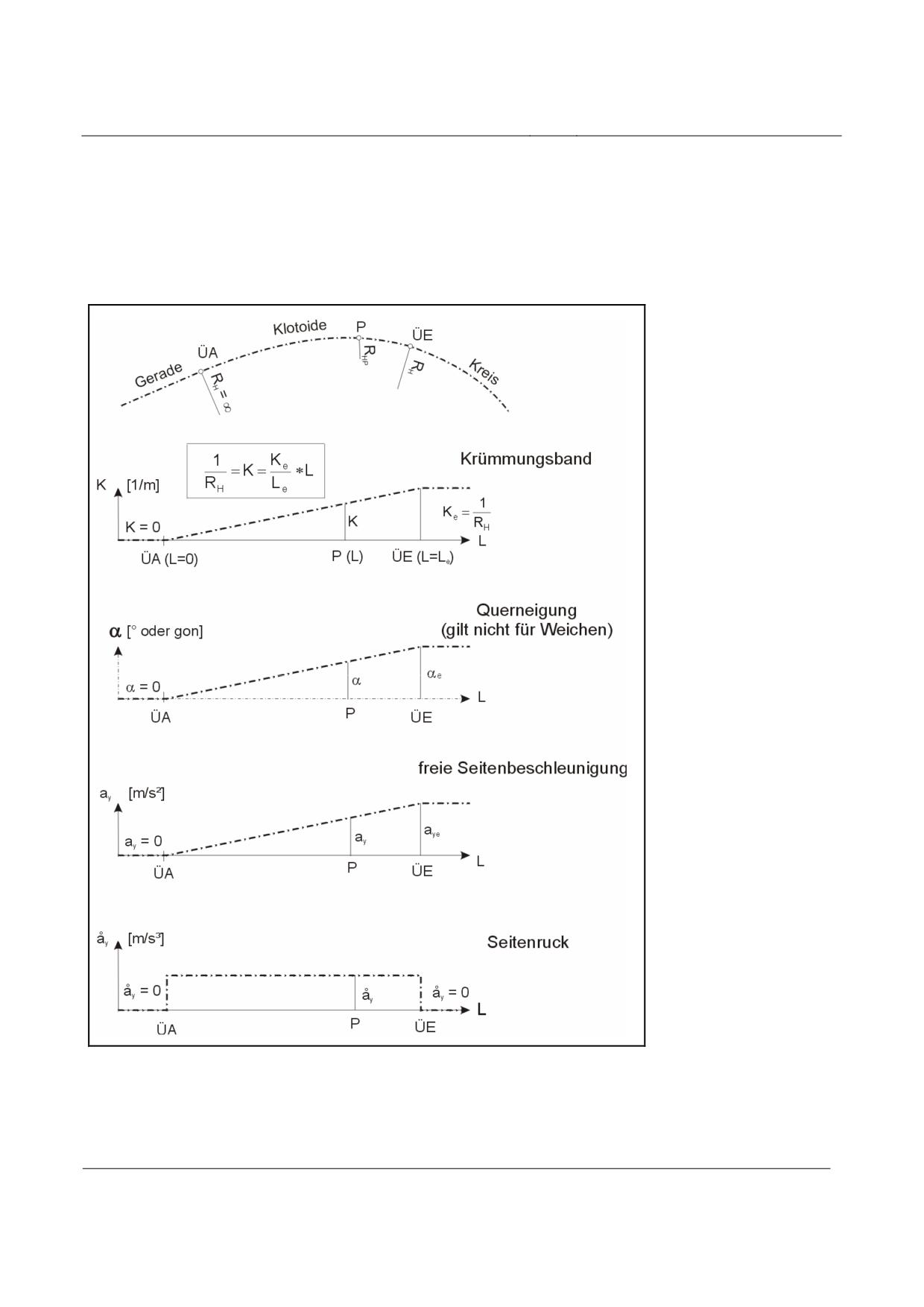
High-speed Maglev system
Maglev Technical Committee
Design principles
Guideway
Krümmungsband = curvature string
oder gon = or gon
Querneigung = lateral incline
freie Seitenbeschleunigung = free lateral acceleration
Seitenruck = lateral jolt]
The lateral incline has a sinusoidal structure in a similar way to the curvature.
Fig. 229:
Geometric characteristics of the clothoids and those concerning travel dynamics
[Key to diagram:
Gerade = straight line
Klotoide = clothoid
Kreis = circle
Title
High-speed Maglev system, design principles
Guideway, Part IV, Routing
Doc. No.:
60640
Version White pa-
Issue date
15.02.2007
Page 11
per
High-speed Maglev system
Maglev Technical Committee
Design principles
Guideway
Krümmungsband = curvature string
oder gon = or gon
Querneigung (gilt nicht für Weichen) = lateral incline (does not apply to points)
freie Seitenbeschleunigung = free lateral acceleration
Seitenruck = lateral jolt]
Title
High-speed Maglev system, design principles
Guideway, Part IV, Routing
Doc. No.:
60640
Version White pa-
Issue date
15.02.2007
Page 12
per
High-speed Maglev system
Maglev Technical Committee
Design principles
Guideway
Vertical plan routing elements
Standard guideway
The standard guideway vertical plan includes the following:
• straight lines (RV = ∞)
• radii (arcs [of a circle], RV = constant)
• clothoids (transition curve)
Between the straight lines and the radii, clothoids shall be engaged to prevent curvature jumps in
the progression of the gradient (vertical jolt åz = ∞).
The maximum permitted longitudinal gradient in the straight lines is laid down under point 6.1.1.
Points
Points should not be arranged in the area of vertical fillets. The maximum permitted longitudinal
gradient in the straight lines is laid down under point 6.1.1.
Title
High-speed Maglev system, design principles
Guideway, Part IV, Routing
Doc. No.:
60640
Version White pa-
Issue date
15.02.2007
Page 13
per

High-speed Maglev system
Maglev Technical Committee
Design principles
Guideway
Routing parameters
Geometric routing parameters
Explicitly identified special cases require authorisation.
Section 3(2) and Section 5(1)(2) of the Maglev Construction and Operation Ordinance apply to e-
xemptions from these provisions.
Limit values for the longitudinal gradient of the guideway
The limit values for the longitudinal gradient of the guideway are listed in Table 141.
Place
Area
Limit value
Stipulated by
Open section of guide-
⏐s⏐= 100‰
Section 13(2) of the
way outside stopping
Maglev Construction
places
and Operation Ordi-
nance
Within stopping places
Platform area
⏐s⏐= 5‰
Section 13(2) of the
Maglev Construction
and Operation Ordi-
nance
Operational-related
⏐s⏐= 100‰
Section 13(2) of the
stopping places
Maglev Construction
in accordance with the
and Operation Ordi-
proof of the halting
nance
function
Other operational stop-
⏐s⏐= 100‰
Section 13(2) of the
ping places
Maglev Construction
in accordance with the
and Operation Ordi-
proof of the halting
nance
function
Stopping places for
⏐s⏐= 5‰
Section 13(2) of the
evacuation purposes
Maglev Construction
and Operation Ordi-
nance
Table 141: Longitudinal gradient of the guideway
Sign convention:
+ s = slope
- s = gradient
Title
High-speed Maglev system, design principles
Guideway, Part IV, Routing
Doc. No.:
60640
Version White pa-
Issue date
15.02.2007
Page 14
per

High-speed Maglev system
Maglev Technical Committee
Design principles
Guideway
Limit values for the lateral incline of the guideway
The guideway levels shall be planned with a lateral incline to eliminate or reduce the unbalanced
lateral acceleration which occurs when going round bends. The limit values are listed in Table 142.
The lateral incline is produced by rotating the guideway superstructures around the guideway axis
which maintain their heights (gradients). Consequently, the vehicle’s centre of gravity always main-
tains the same gap from the guideway axis. When stopping (at platforms or operational stopping
places), the lateral incline causes acceleration towards the inside of the bend.
Place
Area
Limit value
Stipulated by
Open section of gui-
⏐α⏐ = 12°
Section 13(3) of the
deway outside stop-
Maglev Construction
ping places
and Operation Ordi-
nance
⏐α⏐ = 16°
Section 13(3) of the
Maglev Construction
in special cases
and Operation Ordi-
nance
Within stopping pla-
Platform area
⏐α⏐ = 3.0° *
the system as a whole
ces
Operational-related
⏐α⏐ = 6.0°
the system as a whole
stopping places
Corresponds to ay =
1.0 m/s² (inside of the
bend)
Other operational
⏐α⏐ = 12°
the system as a whole
stopping places
Corresponds to ay =
2.0 m/s² (inside of the
bend)
Stopping places for
⏐α⏐ = 6.0°
the system as a whole
evacuation purposes
Corresponds to ay =
1.0 m/s² (inside of the
bend)
Points
⏐α⏐ = 0°
the system as a whole
Upright or bending
position (calculated
where
⏐s⏐ = 0 ‰)
Table 142: Lateral incline of the guideway
Title
High-speed Maglev system, design principles
Guideway, Part IV, Routing
Doc. No.:
60640
Version White pa-
Issue date
15.02.2007
Page 15
per
High-speed Maglev system
Maglev Technical Committee
Design principles
Guideway
*) In Section 13(3) of the Maglev Construction and Operation Ordinance, the permitted lateral in-
cline of a stationary vehicle in the platform area is limited to 3.4°. The maximum permitted lateral
incline of 3.0° is laid down for system-related reasons.
The guideway should be drained via the top side of the guideway superstructures according to the
Guideway design principles for high-speed maglev systems - Part I: Principle requirements.
The minimum lateral incline of the guideway is
⏐α⏐ = 1.15 ° (corresponds to 2%).
(Areas where the direction of the lateral incline changes (e.g. S jolts) are exempt, along with par-
king and maintenance lanes, stations and points).
Sign convention:
+ α = clockwise rotation (viewed in the direction of the chainage)
+ α = anti-clockwise rotation (viewed in the direction of the chainage)
Title
High-speed Maglev system, design principles
Guideway, Part IV, Routing
Doc. No.:
60640
Version White pa-
Issue date
15.02.2007
Page 16
per
High-speed Maglev system
Maglev Technical Committee
Design principles
Guideway
Guideway distortion and the minimum permitted distortion
length
The distortion section is the transition area between constant lateral incline sections.
The start and end points of distortion sections and transition curves in the case of horizontal plan
routing should coincide with the position.
In a particular case, distortion sections can also be arranged in guideway sections with a constant
horizontal plan curvature (also refer to the formula for calculating the lateral incline α where Le =
the length of the distortion in point 5.2.1).
The progression of the distortion in the cross-fall string should be similar to the progression of the
curvature in the horizontal plan routing.
When using sinusoids in the horizontal plan routing, the guideway distortion should be of sinusoi-
dal design. However, if distortion coincides with a clothoid in the horizontal plan, the distortion
shall be linear, i.e. with a uniform change in the lateral incline over the length of the element (see
fig. 229).
Distortion
Stipulated by
Maximum value
⏐∆αmax⏐ = 0.10 °/m
the system as a whole
(geometry of the vehic-
le)
Limit value according
⏐∆αmax⏐ = 0.15 °/m
the system as a whole
to the project-specific
(geometry of the vehic-
agreement
le)
The minimum permitted length of the distortion section is established from the maximum permitted
distortion, the maximum lateral jolt (see 6.2.3.1) and the maximum vertical jolt (see 6.2.3.2 and
6.2.4).
Title
High-speed Maglev system, design principles
Guideway, Part IV, Routing
Doc. No.:
60640
Version White pa-
Issue date
15.02.2007
Page 17
per
High-speed Maglev system
Maglev Technical Committee
Design principles
Guideway
Minimum permitted horizontal radius
As regards arc radii without unbalanced lateral acceleration, the following applies:
v
2
2
(
)
⋅cosα
⋅cos
β
3,6
R
=
H
2
⎛
v
⎞
(
)
⎜
3,6
g⋅cosβ
+
⎟⋅sinα
⎜
⎟
-
R
⎜
V
⎟
⎝
⎠
ay = 0 m/s²
(1)
As regards arc radii with non-compensated, unbalanced lateral acceleration, the following applies:
v
2
2
(
)
⋅
cosα
⋅cos
β
3,6
R
=
H
⎛
v
2
⎞
(
)
⎜
3,6
a
y
+
g⋅cosβ
+
⎟⋅sinα
⎜
⎟
⎜
-
R
V
⎟
⎝
⎠
ay ≤ ay max
(2)
Sign convention:
+ RH = clockwise curve
(viewed in the direction of the chainage)
- RH = anti-clockwise curve (viewed in the direction of the chainage)
The limit values for ay are listed under point 6.2.2.2. Consideration must also be given to the fact
that the values for v, α, β and Rv may not remain constant over the entire arc of the circle but may
alter with forward movement along the space curve. RH is calculated using the above formulae for a
single point on the space curve. Where a horizontal plan curvature is superimposed with a vertical
fillet, the conditions pertaining to the Rx,z criterion and the Rx,y criterion must also be heeded (see
point 6.1.6).
Minimum permitted
Stipulated by
horizontal radius
Limit value
⏐RH min⏐ = 350 m
the system as a whole
(geometry of the vehic-
le)
Title
High-speed Maglev system, design principles
Guideway, Part IV, Routing
Doc. No.:
60640
Version White pa-
Issue date
15.02.2007
Page 18
per
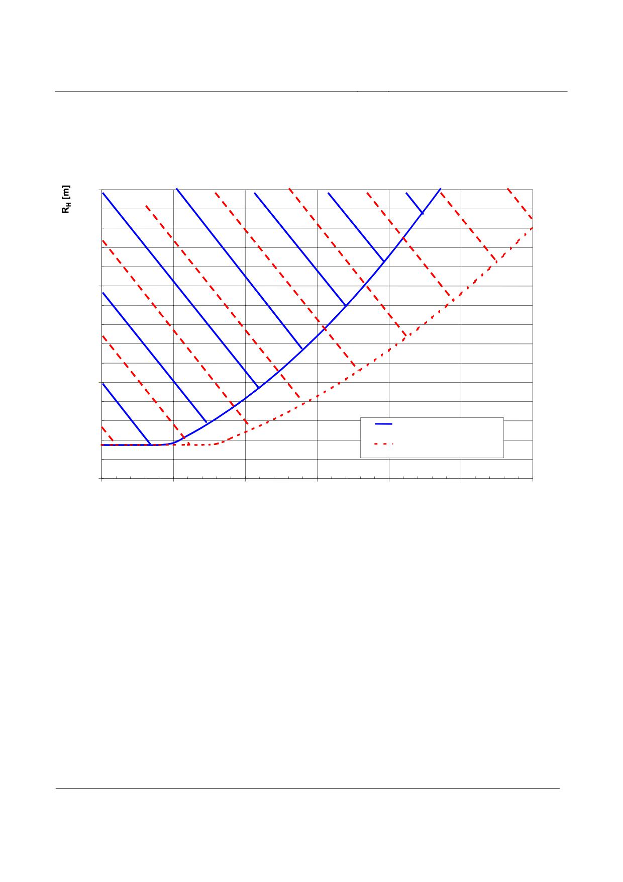
High-speed Maglev system
Maglev Technical Committee
Design principles
Guideway
Fig. 230 below shows an example of the progression of the minimum permitted horizontal radius
depending on the speed of the vehicle if stipulations in terms of travel dynamics are to be taken into
consideration (see Chapter 6.2.2.2). In this example, a lateral incline of the guideway of 12° is as-
sumed and the smallest horizontal radii are sought for an unbalanced lateral acceleration of 0.0
m/s² or 1.5 m/s².
3000
2000
1000
Min zulässiger Horizontalradius
(bei ay = 0,0 m/s², α = 12°)
Min zulässiger Horizontalradius
(bei ay = 1,5 m/s², α = 12°)
0
50
100
150
200
250
300
350
V [km/h]
Fig. 230:
Minimum permitted horizontal radius
[Key to diagram:
Min. zulässiger Horizontalradius (bei ay =
) = minimum permitted horizontal radius (where ay =
)]
Title
High-speed Maglev system, design principles
Guideway, Part IV, Routing
Doc. No.:
60640
Version White pa-
Issue date
15.02.2007
Page 19
per
High-speed Maglev system
Maglev Technical Committee
Design principles
Guideway
Minimum permitted vertical radius
The radii chosen should be such that the standard acceleration which occurs is as low as possible.
Using the limit values for acceleration which are cited under point 6.2.1, the minimum fillet radii
values are established as follows:
v
2
(
)
⋅cosα
3,6
R
=
V min
2
2
sinα⋅cos
β
v
g⋅(cosα⋅cosβ
-1)+(
)
⋅
−azmax
3,6
R
H
(3)
Sign convention:
+ RV = peaks
- RV = troughs
Different limit values for az max apply to peaks and troughs.
Here, too, a point on the space curve is calculated and consideration must be given to the possible
change in v, α, β and RH during the journey as a result of the radius when determining the result.
Minimum permitted
Stipulated by
vertical radius
Limit value
⏐RV min⏐ = 530 m
the system as a whole
(geometry of the vehic-
le)
Points should not be located in the area of vertical fillets.
The sign convention is required on account of using transition curves in the gradient calculation.
Title
High-speed Maglev system, design principles
Guideway, Part IV, Routing
Doc. No.:
60640
Version White pa-
Issue date
15.02.2007
Page 20
per
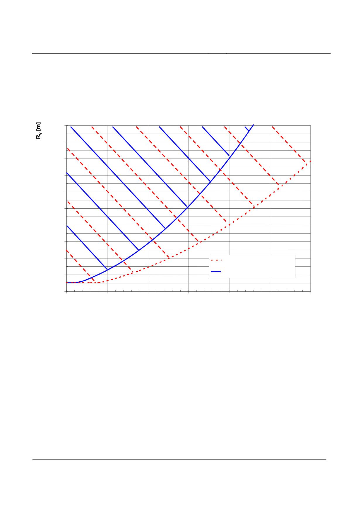
High-speed Maglev system
Maglev Technical Committee
Design principles
Guideway
Fig. 231 below provides an example of the minimum permitted vertical diameter depending on the
speed of the vehicle for the maximum standard acceleration which is permitted each time at peaks
and in troughs. The stipulations concerning travel dynamics are used to calculate RV min according
to equation (3) above.
10000
9000
8000
7000
6000
5000
4000
3000
2000
Min zulässiger Halbmesser (Wanne)
Min zulässiger Halbmesser (Kuppe)
1000
0
50
100
150
200
250
300
350
V [km/h]
Fig. 231:
Minimum permitted vertical radius
[Key to diagram:
Min. zulässiger Halbmesser (Wanne) = minimum permitted radius (trough)
Min. zulässiger Halbmesser (Kuppe) = minimum permitted radius (peak)]
Title
High-speed Maglev system, design principles
Guideway, Part IV, Routing
Doc. No.:
60640
Version White pa-
Issue date
15.02.2007
Page 21
per

High-speed Maglev system
Maglev Technical Committee
Design principles
Guideway
Rx,z criterion
When superimposing a gradient curvature (radius) with a horizontal curvature (radius), the Rx,z cri-
terion (spatial radius) must be heeded.
2
1
cosα
sinα
⋅
cos
β
=
-
R
R
R
x,
z
V
H
(4)
Refer to Chapters 6.1.1 to 6.1.5 for the sign conventions of the parameters used.
Minimum permitted
Stipulated by
Rx,z criterion
Limit value
⏐Rx,z min⏐ = 530 m
the system as a whole
where ∆α = 0.00 °/m (geometry of the vehicle)
With additional superimposition involving distortion, the spatial radius depends on the distortion
which exists locally.
The limit values laid down in Table 143 depend on the geometry of the vehicle which is specific to
the particular project. (The Intermediate values must be determined by linear interpolation).
∆α
[°/m]
0.00
0.01
0.02
0.03
0.04
0.05
Rx,z min [m]
530
550
590
630
670
710
∆α
[°/m]
0.06
0.07
0.08
0.09
0.10
0.11
Rx,z min [m]
770
830
900
990
1100
1230
∆α
[°/m]
0.12
0.13
0.14
0.15
Rx,z min [m]
1410
1640
1950
2430
Table 143: Limit values for Rx,z in the case of guideway distortion
Title
High-speed Maglev system, design principles
Guideway, Part IV, Routing
Doc. No.:
60640
Version White pa-
Issue date
15.02.2007
Page 22
per
High-speed Maglev system
Maglev Technical Committee
Design principles
Guideway
Rx,y criterion
When superimposing a gradient curvature (radius) with a horizontal curvature (radius), the Rx,y cri-
terion (spatial radius) must be heeded.
2
1
sinα
cosα
⋅
cos
β
=
+
R
R
R
x,
y
V
H
(5)
Refer to Chapters 6.1.1 to 6.1.5 for the sign conventions of the parameters used.
Minimum permitted
Stipulated by
Rx,y criterion
Limit value
⏐Rx,y min⏐ = 350 m
the system as a whole
(geometry of the vehicle)
The minimum permitted radius for the Rx,z criterion shall be set at 530 m. On this basis, the limit
value for the Rx,y criterion of 350 m can also only be achieved by means of special routing geo-
metries.
As regards possible superimposition involving distortion, project-specific regulations must be laid
down depending on the geometry of the vehicle.
Title
High-speed Maglev system, design principles
Guideway, Part IV, Routing
Doc. No.:
60640
Version White pa-
Issue date
15.02.2007
Page 23
per
High-speed Maglev system
Maglev Technical Committee
Design principles
Guideway
Driving dynamic specifications
Target line speed and permissible line speed
The target line speed is the local minimum, defined on the basis of the maximum running speed, the
target speed from the point of view of ride comfort and further project specifications (see /MSB AG-
ABK&DEF/ for diagram).
For the guideway dimensioning, the following upper limits are defined for the permissible speed for
guideways and tunnels:
Line section
Permissible speed
Defined by
Open track
vmax ≤ 500 km/h
Guideway (steady loads)
Tunnel sections (de-
vmax ≤ 500 km/h
Guideway (steady loads)
pendent upon cross-
section)
Guideway (steady loads)
Switches in straight
vmax ≤ 500 km/h
position
Switches in turnout
Model-specific
Guideway (steady loads)
position
Taking into account also the permissible speed for the vehicle (project-specific or /MSB AG-
GESAMT/), the permissible speed for the line is determined from the above-mentioned permissible
speeds.
The programmed speed is the minimum of target line speed and permissible line speed.
The actual driving profile required for the driving-dynamic simulations (see /MSB AG-ABK&DEF/
for diagram) is generated by additional drive simulations, in which the actual project-related per-
formance of the drive is taken into account.
Title
High-speed Maglev system, design principles
Guideway, Part IV, Routing
Doc. No.:
60640
Version White pa-
Issue date
15.02.2007
Page 24
per
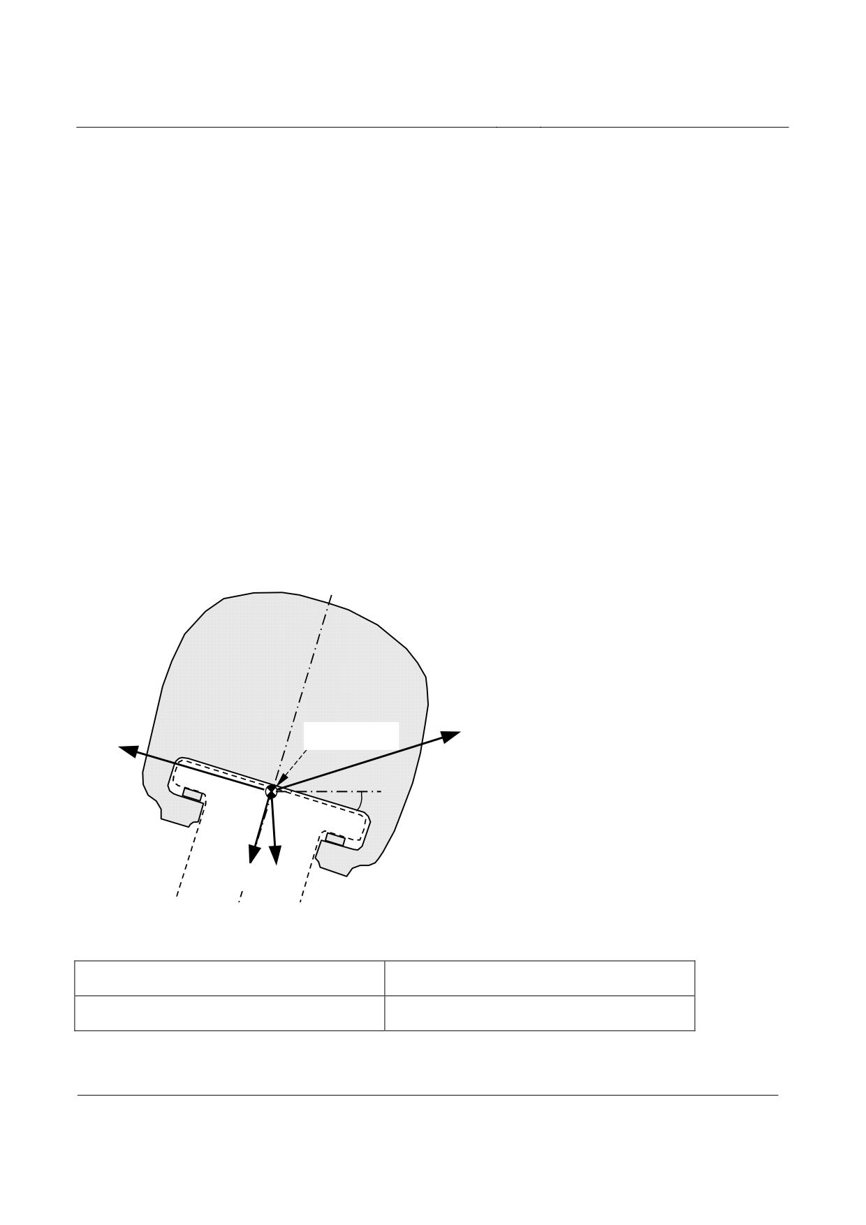
High-speed Maglev system
Maglev Technical Committee
Design principles
Guideway
Accelerations
Depending upon their direction of action, the accelerations are divided into:
• Drive or braking acceleration
ax
• Uncompensated lateral acceleration
ay
• Normal acceleration (comfort value)
az
• Normal case acceleration (acceleration due to gravity)
g
The acceleration limit values for the uncompensated lateral acceleration and for the normal accele-
ration should be adhered to by the three-dimensional guideway axis (three-dimensional curve). The
drive subsystem is responsible for adherence to the limit values for the drive or braking acceleration
(see /MSB AG-ANT/).
For reasons of ride comfort, the lowest possible uncompensated lateral and normal acceleration va-
lues should be striven for by a suitable choice of route parameters. At switches, compensation for
lateral acceleration is not possible since the guideway may not be tilted.
Figure 232 shows in cross-section a high-speed Maglev vehicle (viewed in direction of increasing
kilometrage) upon which the acceleration in question acts with a positive sign.
+ax
Raumkurve
+ay
(Blickrichtung =
aufsteigende
+α
Kilometrierung)
+az
+g
Figure 232: Sign of accelerations
Raumkurve
Three-dimensional curve
(Blickrichtung = …
(Viewing direction = rising kilometrage)
Title
High-speed Maglev system, design principles
Guideway, Part IV, Routing
Doc. No.:
60640
Version White pa-
Issue date
15.02.2007
Page 25
per
High-speed Maglev system
Maglev Technical Committee
Design principles
Guideway
Drive and braking acceleration
The drive subsystem is responsible for adherence to the limit values for the drive / braking accelera-
tion (see /MSB AG-ANT/).
Adherence to the limit values for the drive and braking acceleration should be checked at selected
points, taking into consideration the predetermined maximum driving profile and the slope of the
guideway resulting from the route study.
Drive and braking
Determined by
acceleration
Limit value
|ax max | = 1.5 m/s²
MbBO
Comfort-determined maximum values (ride comfort) can be defined on a project-specific basis.
Uncompensated lateral acceleration
The uncompensated lateral acceleration is calculated as follows:
v
2
⎛
v
2
⎞
(
)
(
)
3.6
2
⎜
3.6
⎟
a
y
=
⋅cosα⋅cos
β-
g⋅cosβ
+
⋅sinα
(6)
⎜
⎟
R
⎜
-
R
⎟
H
V
⎝
⎠
The sign of the calculated uncompensated lateral acceleration indicates the direction of the accele-
ration for the passenger:
In the case of a positive sign towards the left in direction of travel,
In the case of a negative sign towards the right in direction of travel.
Limit value
Uncompensated late-
Determined by
ral acceleration
For normal guideway |ay max | = 1.5 m/s²
MbBO (towards outside of curve)
For switches
|ay max | = 2.0 m/s²
Complete system (dimensioning of
switches)
Comfort-determined maximum values (ride comfort) can be defined on a project-specific basis.
If the speed of the vehicle is optimally adapted to the lateral tilt and the radius no lateral accelera-
tion will occur (ay = 0).
If the speed is higher, it acts towards the outside of the curve, i.e. upwards on the tilted surface of
guideway as “excess acceleration”.
Title
High-speed Maglev system, design principles
Guideway, Part IV, Routing
Doc. No.:
60640
Version White pa-
Issue date
15.02.2007
Page 26
per
High-speed Maglev system
Maglev Technical Committee
Design principles
Guideway
If it is lower, it acts towards the inside of the curve, i.e. downwards on the tilted surface of the gui-
deway as deficient acceleration (descending force).
The relationship of the current horizontal radius in the direction of travel, the associated direction of
guideway lateral tilt and the sign of ay from the calculation is shown in Table 144 for information.
Right-hand curve and positive
Left-hand curve and negative la-
lateral tilt
teral tilt
Route parameters in
RH and α with positive sign (+)
RH and α with negative sign (-)
direction of travel
ay with positive sign
Acceleration in direction of
Acceleration in direction of tra-
(+)
travel towards the left = excess
vel towards the left =
acceleration
deficient acceleration
ay with negative sign
Acceleration in direction of
Acceleration in direction of tra-
(-)
travel towards the right
vel towards the right
= deficient acceleration
= excess acceleration
Table 144: Direction of excess and deficient acceleration
In the /MSB AG-FW BEM/, in deviation from these design principles, the direction of action of the
free lateral acceleration is differentiated exclusively according to whether it is towards the inside or
outside of curve. A negative sign in the /MSB AG-FW BEM/ always describes acceleration towards
the inside of the curve (deficient acceleration) and a positive sign always describes an acceleration
towards the outside of the curve (excess acceleration).
Title
High-speed Maglev system, design principles
Guideway, Part IV, Routing
Doc. No.:
60640
Version White pa-
Issue date
15.02.2007
Page 27
per
High-speed Maglev system
Maglev Technical Committee
Design principles
Guideway
Normal acceleration (comfort value)
The normal acceleration (comfort value) resulting from the routing of the three-dimensional curve
is calculated as follows:
2
2
v
⎛
v
⎞
(
)
(
)
3,6
2
⎜
3,6
⎟
a
=
⋅sinα
⋅cos
β
+
g⋅cosβ
+
⋅cosα
−g
(7)
z
R
⎜
-R
⎟
H
V
⎝
⎠
The normal acceleration (comfort value) within a twisted line section (rotation about the three-
dimensional curve) is found as follows:
2
⎛
v
⎞
(
)
α
-
α
⎛
L
⎞
e
a
⎜
3.6
⎟
a
=±b
⋅2π
⋅
⋅
⋅sin⎜2π
⋅
⎟
(8)
z
G
⎜
⎟
⎜
⎟
ρ°
⎜
L
⎟
L
e
⎝
e
⎠
⎝
⎠
The extreme values of the above-mentioned normal acceleration (comfort value) are as follows
when L = Le / 4 and L = 3 Le / 4:
2
⎛
v
⎞
(
)
α
-
α
⎜
⎟
e
a
3.6
a
=±
b
⋅2π
⋅
⋅
(9)
z
G
⎜
⎟
ρ°
⎜
L
⎟
e
⎝
⎠
The normal acceleration resulting from the twist acts with the opposing sign on the right-hand and
left-hand side of the vehicle. In the addition of the two above-mentioned normal accelerations the
least favourable case should always be calculated, i.e. the sign of the second component should be
selected according to the normal acceleration components from the route in front view.
Limit value
Normal acceleration
Determined by
For humps
az max = -0.6 m/s²
Complete system (dimensioning of
guideway), recommendation of
MbBO
For valleys
az max = +1.2 m/s²
Complete system (dimensioning of
guideway), recommendation of
MbBO
Comfort-determined maximum values (ride comfort) can be defined on a project-specific basis.
Title
High-speed Maglev system, design principles
Guideway, Part IV, Routing
Doc. No.:
60640
Version White pa-
Issue date
15.02.2007
Page 28
per
High-speed Maglev system
Maglev Technical Committee
Design principles
Guideway
Jerks
Jerks are differential changes in the acceleration per unit time.
The jerks are calculated based upon the three-dimensional guideway axis (three-dimensional curve).
Transition curves should be routed so that the maximum values for the jerks (differential changes in
acceleration per unit time) are not exceeded.
The jerks are divided as follows depending upon direction of action:
•
Lateral jerk
åy
•
Vertical jerk
åz
•
Longitudinal jerk
åx
•
Omnidirectional jerk (not at switches)
åo
The lowest possible jerk values increase the subjective ride enjoyment of the passengers (good ride
comfort). This can be achieved for example by extending the transition curve in the ground plan.
The formulae listed below for the calculation of the jerk values are only applicable if the path of the
curve and twist sections are the same. If no analogous path is available, adherence to the limit va-
lues should be checked at selected points.
Title
High-speed Maglev system, design principles
Guideway, Part IV, Routing
Doc. No.:
60640
Version White pa-
Issue date
15.02.2007
Page 29
per
High-speed Maglev system
Maglev Technical Committee
Design principles
Guideway
Lateral jerk
The lateral jerk is calculated as follows:
• For clotoids
∆a
y
v
å
=
⋅
(10)
y
L
3.6
K
• For sinusoids (for the maximum value)
∆a
y
v
å
=
2⋅
⋅
(11)
y
L
3.6
S
Maximum value
Lateral jerk
Determined by
In principle
|åy max| = 0.5 m/s³
Complete system (ride comfort)
Exceptions, e.g. for vici-
|åy max| = 1.0 m/s³
Complete system (ride comfort)
nity of stations
For switches (turnout
|åy max| = 2.0 m/s³
Complete system (ride comfort)
position)
To the extent that standing passengers can be expected on a regular basis in the regional service
when the high-speed Maglev system is used, lower permissible lateral jerk values should be de-
fined for the negotiation of switches, on a project-specific basis.
Title
High-speed Maglev system, design principles
Guideway, Part IV, Routing
Doc. No.:
60640
Version White pa-
Issue date
15.02.2007
Page 30
per
High-speed Maglev system
Maglev Technical Committee
Design principles
Guideway
Vertical jerk
The vertical jerk is calculated as follows:
∆a
z
v
å
=
⋅
(12)
z
L
3.6
K
The vertical jerk component within a twistroad (rotation about the three-dimensional curve) is as
follows:
3
⎛
v
⎞
(
)
α
-
α
⎛
L
⎞
2
e
a
⎜
3.6
⎟
å
=±b
⋅4π
⋅
⋅
⋅cos⎜2π
⋅
⎟
(13)
z
G
⎜
⎟
⎜
⎟
ρ°
⎜
L
⎟
L
e
⎝
e
⎠
⎝
⎠
The extreme values of the above-mentioned vertical jerk component are as follows where L = 0, L
= Le / 2 and L = Le:
3
⎛
v
⎞
(
)
α
-
α
2
e
a
⎜
3.6
⎟
å
=±b
⋅4π
⋅
⋅
(14)
z
G
⎜
⎟
ρ°
⎜
L
⎟
e
⎝
⎠
The vertical jerk component resulting from the twist acts with an opposing sign on the right-hand
and left-hand sides of the vehicle. In the addition of the two above-mentioned vertical jerk compo-
nents the least favourable case should always be used for the calculation, i.e. the sign of the second
component should be selected according to that of the vertical jerk component from the routing of
the three-dimensional curve.
Maximum value
Vertical jerk
Determined by
In principle
|åz max| = 0.5 m/s³
Complete system (ride comfort)
Exceptions, e.g. for the
|åz max| = 1.0 m/s³
Complete system (ride comfort)
vicinity of stations
Special cases with increased vertical jerk are permissible after testing for compatibility in the indi-
vidual case.
Title
High-speed Maglev system, design principles
Guideway, Part IV, Routing
Doc. No.:
60640
Version White pa-
Issue date
15.02.2007
Page 31
per
High-speed Maglev system
Maglev Technical Committee
Design principles
Guideway
Longitudinal jerk
The longitudinal jerk is not primarily dependent upon the path of the three-dimensional curve but
upon the path of speed.
The operator requirements of longitudinal jerk should be adhered to by the driving profile.
Omnidirectional jerk
The spatial superposition of longitudinal jerk, lateral jerk and vertical jerk yield the omnidirectional
jerk.
This is calculated as follows:
2
2
2
å =
åx+ åy+ å
z
(15)
o
Maximum value
Omnidirectional jerk
Determined by
In principle
|åo max| = 1.0 m/s³
Complete system (ride comfort)
Special cases with increased omnidirectional jerk are permissible after testing for compatibility in
the individual case.
No maximum value for omnidirectional jerk is specified for switches (turnout position).
Title
High-speed Maglev system, design principles
Guideway, Part IV, Routing
Doc. No.:
60640
Version White pa-
Issue date
15.02.2007
Page 32
per
High-speed Maglev system
Maglev Technical Committee
Design principles
Guideway
Minimum length of sinusoid
In the route path the sinusoids in question (including in s-twist amongst others) are defined by the
length L and the radii RHa or RHe, whereby a radius can also be RH = ∞ (straight).
The minimum length is found from the criteria of the maximum lateral jerk, the maximum permis-
sible twist or the maximum vertical jerk using the formulae listed below, whereby the greatest
length is always definitive.
a ⋅SGN(R
)-a
⋅
SGN(R
)
y,e
y,a
H, e
H,
a
v
L
=
2⋅
⋅
(16)
S min
å
3.6
y max
α
−α
e
a
L
=
2⋅
(17)
S min
∆α
max
α
−
α
3
2
e
a
L
=
3
(v
)
⋅b
⋅4π
⋅
(18)
S min
3.6
G
ρ°
⋅å
z max
The listed formulae for the calculation of the minimum length of the sinusoids only apply if curve
and twistroads have identical start and end points along the guideway axis. If no identical path e-
xists, particular care should be taken that the limit values are adhered to.
In the event of the superposition of twists with vertical transitions, adherence to the limit values
should be checked at selected points, since the vertical jerk component from the three-dimensional
curve is not taken into consideration in the above-mentioned formula (see 0).).
Title
High-speed Maglev system, design principles
Guideway, Part IV, Routing
Doc. No.:
60640
Version White pa-
Issue date
15.02.2007
Page 33
per
High-speed Maglev system
Maglev Technical Committee
Design principles
Guideway
Minimum length of clotoid
In the layout of the line the clotoids in question are defined by the radius (RH) or the radius (RV) of
the following arc and the length L of the transition curve. L should be selected such that the maxi-
mum lateral or vertical jerk is not exceeded. The minimum length is found from the formulae listed
below:
In the ground plan (in the standard guideway only for switches or at route obstacles where V < 100
km/h)
∆
ay
v
L
=
⋅
(19)
K min
å
3.6
y max
In the vertical plan
∆
az
v
L
=
⋅
(20)
K min
å z
3.6
max
In the case of the superposition of twists with vertical transitions, particular care should be taken
that the limit values are adhered to, since in the above-mentioned formula the vertical jerk compo-
nent from the twist is not taken into account (see 0).
Title
High-speed Maglev system, design principles
Guideway, Part IV, Routing
Doc. No.:
60640
Version White pa-
Issue date
15.02.2007
Page 34
per
High-speed Maglev system
Maglev Technical Committee
Design principles
Guideway
Comfort criteria in relation to the overall journey time for the
routed section
For the routing, not only should the specification of the individual route elements and their combi-
nation be checked from a system-technical point of view, the criteria of ride comfort should also be
taken into account. In this connection, the overall sequence of route elements and their effect upon
the passenger are important. In what follows the dimensioning and evaluation of the comfort of a
planned route section are shown based upon the line layout and the envisaged maximum driving
profile for this, independently of the vehicle and the passenger behaviour.
The effective value of accelerations (RMS value) is drawn upon as an evaluation criterion for the
assessment of ride comfort. This value is found using the equation (21):
T
1
2
a
=a
=
a
(t)dt
(21)
eff
rms
∫
T
0
where a(t) = acceleration amplitude at point in time t
and T
= overall journey time (complete section length)
For the route design the following requirements are defined:
For the ground plan routing
- The effective value of uncompensated lateral acceleration must lie below the (sometimes
extrapolated) limit values shown in the diagram “Ride comfort for longitudinal and lateral
acceleration”. This diagram is shown in Figure 232.
- The action time corresponds to the overall journey time.
- A minimum length for the ground plan elements ‘straight line’ and ‘circle’ is not necessary
for the consideration of the effective value.
For vertical plan routing
- The effective value of the normal acceleration must lie below the limit vales shown in the
diagram “Ride comfort for normal acceleration”, for example to avoid kinetosis effects (tra-
vel sickness) this should be 20% below the limit value. This diagram is shown in Figure
234.
- The action time corresponds with the overall journey time.
- The periodic arrangement of transitions over an extended route section should be avoided.
- A minimum length for the vertical plan elements ‘straight line’ and ‘radius’ is not necessary.
Title
High-speed Maglev system, design principles
Guideway, Part IV, Routing
Doc. No.:
60640
Version White pa-
Issue date
15.02.2007
Page 35
per
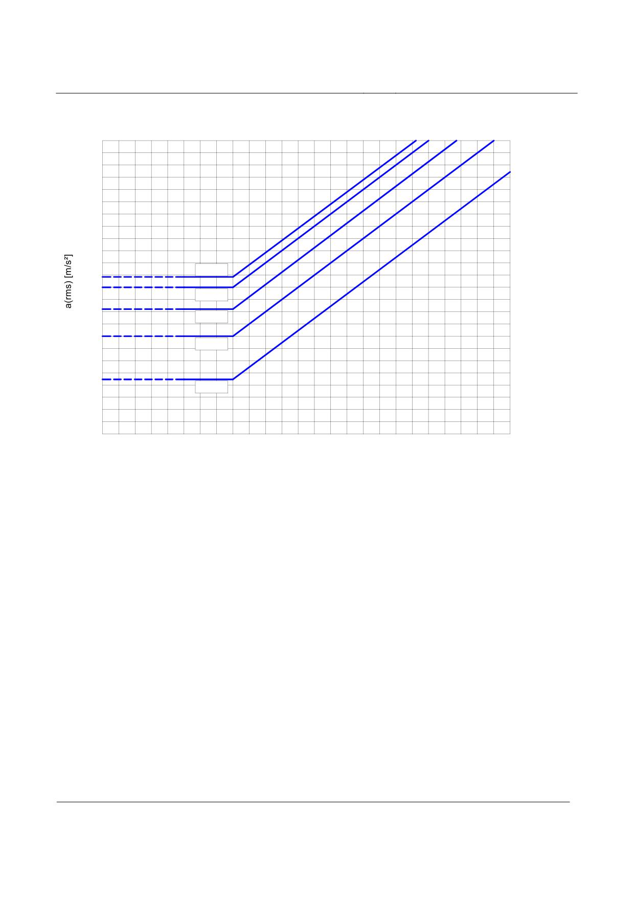
High-speed Maglev system
Maglev Technical Committee
Design principles
Guideway
20
16
12,5
10
8,0
6,3
5,0
4,0
3,15
2,5
2,0
16 min.
1,6
1,25
25 min.
1,0
0,8
1 h
0,63
0,50
2,5 h
0,40
0,315
0,25
0,20
8 h
0,16
0,125
0,10
0,0164 0,5 0,63,8 1,0 1,25,6 2,0 2,5 3,15,0 5,0 6,3 8,0 10
12,516 20 25 31,540 50 63 80
Frequency [Hz]
Acceleration limits as a function of the frequency and action time
Figure 233: Ride comfort for longitudinal and lateral acceleration (according to ISO 2631)
Title
High-speed Maglev system, design principles
Guideway, Part IV, Routing
Doc. No.:
60640
Version White pa-
Issue date
15.02.2007
Page 36
per
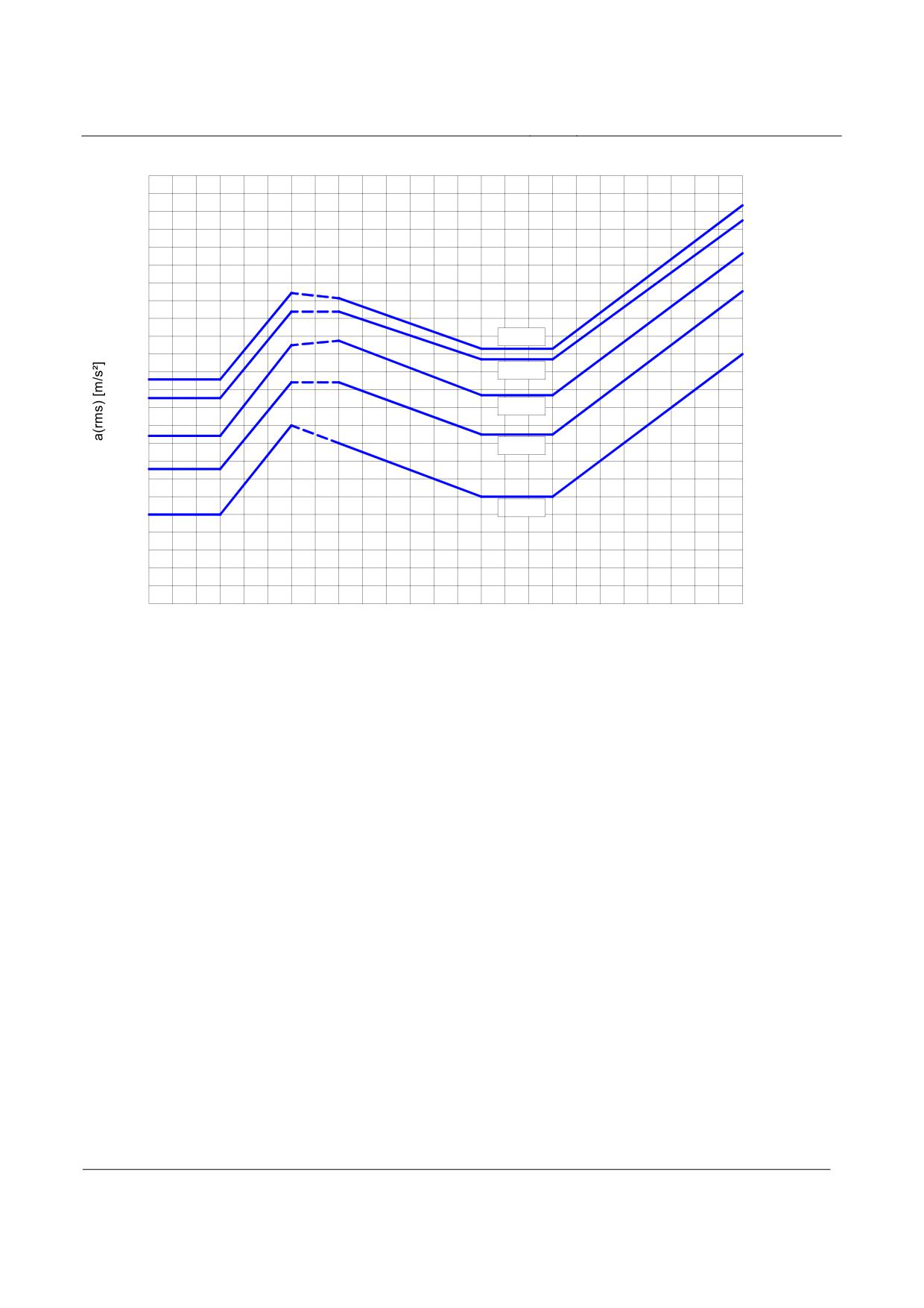
High-speed Maglev system
Maglev Technical Committee
Design principles
Guideway
20
16
12,5
10
8,0
6,3
5,0
4,0
3,15
2,5
16 min.
2,0
1,6
25 min.
1,25
1,0
1 h
0,8
0,63
2,5 h
0,50
0,40
0,315
8 h
0,25
0,20
0,16
0,125
0,10
0,0
0,200,250,3
0,4 0,5 0,630,8 1,0 1,251,6 2,0 2,5 3,154,0 5,0 6,3 8,0 10
12,516 20 25 31,540
Frequency [Hz]
Acceleration limits as a function of the frequency and action time
Figure 234: Ride comfort - normal acceleration (according to ISO 2631)
Title
High-speed Maglev system, design principles
Guideway, Part IV, Routing
Doc. No.:
60640
Version White pa-
Issue date
15.02.2007
Page 37
per
High-speed Maglev system
Maglev Technical Committee
Design principles
Guideway
Support division and field widths
Single track guideway
After the determination of the three-dimensional curve path the field widths preferred from a tech-
nical and economic point of view for further planning should be considered. The support divisions
relate to the defined field widths (/MSB AG-FW ÜBG/) and are assigned to the three-dimensional
curve.
The field widths are determined on a project-specific basis.
Shorter field widths can also be used at route obstacles. It is possible to reduce the field width by an
integer multiple of a groove / tooth period (86 mm). The calculation of the system lengths of gui-
deway beams is performed using the following formula:
L = n×1032-m×86
(22)
where m ≤ 4 (number of reductions)
Title
High-speed Maglev system, design principles
Guideway, Part IV, Routing
Doc. No.:
60640
Version White pa-
Issue date
15.02.2007
Page 38
per
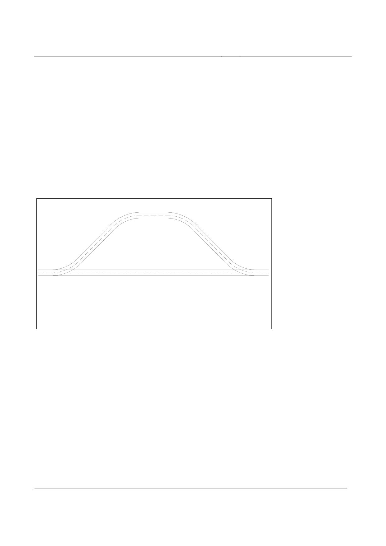
High-speed Maglev system
Maglev Technical Committee
Design principles
Guideway
Double or multiple track guideway
In the case of the support division for double / multiple guideways, reduced field widths (/MSB
AG-FW ÜBG, 7.1) can also be used in order to achieve an approximately radial arrangement of the
support heads. Track switching equipment connect routing axis sections.
The spatial lengths of these routing axis sections between line changing devices must be an integer
multiple of a drive period (516 mm).
These routing axis sections can be shortened by an integer multiple of a groove / tooth period (86
mm).
Figure 235 shows as an example two routing axes that run from a common start point in a track
switching device to a common end point in a track switching device and the spatial lengths of which
must comply with the stated condition.
Axis 1
Axis 2
Length of axis 1: a * 1032 + n * 86 [mm]
Length of axis 2: b * 1032 + n * 86 [mm]
Figure 235: Three-dimensional curve lengths in the case of multiple track guideway
In the case of geometric constraints the deviations of individual routing axis sections (< 516 mm)
from the am/ condition can be uniformly distributed among the field widths within this routing axis
section.
As a guide value for planning, a maximum 6.5 mm extension or up to 0.5 mm reduction can be used
for a field width of 24.7680 m.
Title
High-speed Maglev system, design principles
Guideway, Part IV, Routing
Doc. No.:
60640
Version White pa-
Issue date
15.02.2007
Page 39
per

High-speed Maglev system
Maglev Technical Committee
Design principles
Guideway
Guideway pitch and clearance
Guideway pitch
In the routing of parallel lines at least the guideway pitches described in Table 2 (in relation to the
design speed Ve) should be adhered to.
In addition, there is a differentiation between the minimum guideway pitch due to the lateral tilt (α)
and the horizontal radius (RH) used to avoid the intersection of clearances in category 1 (Ve ≤ 300
km/h).
This rule applies only for lateral tilts up to a maximum of 12° and where the three-dimensional
curve heights (gradients) are the same for adjacent tracks. If the gradient heights are not the same
the clearances of both tracks should be investigated with regard to a possible intersection and the
guideway pitch S modified accordingly.
Category
Design speed
Lateral tilt
Horizontal
Guideway pitch S
α
radius RH
ve
[km/h]
[°]
[m]
[m]
1
ve ≤ 300
4.40
α > 10°
4.50
5° < α ≤ 10°
RH ≤ 3500
2
300 < ve ≤ 400
4.80
3
400 < ve ≤ 500
5.10
Table 145: Guideway pitch
Accuracy
The guideway pitch should be adhered to 2 decimal places (in accordance with /MbBO/).
Non-parallelism of sinusoids
In the routing of parallel lines, sinusoids cannot be routed such that they are precisely geometrical-
ly parallel.
The deviations are included in the space requirement for positional deviations and tolerances of the
guideways in relation to the three-dimensional curve and need not be taken into account here.
Title
High-speed Maglev system, design principles
Guideway, Part IV, Routing
Doc. No.:
60640
Version White pa-
Issue date
15.02.2007
Page 40
per
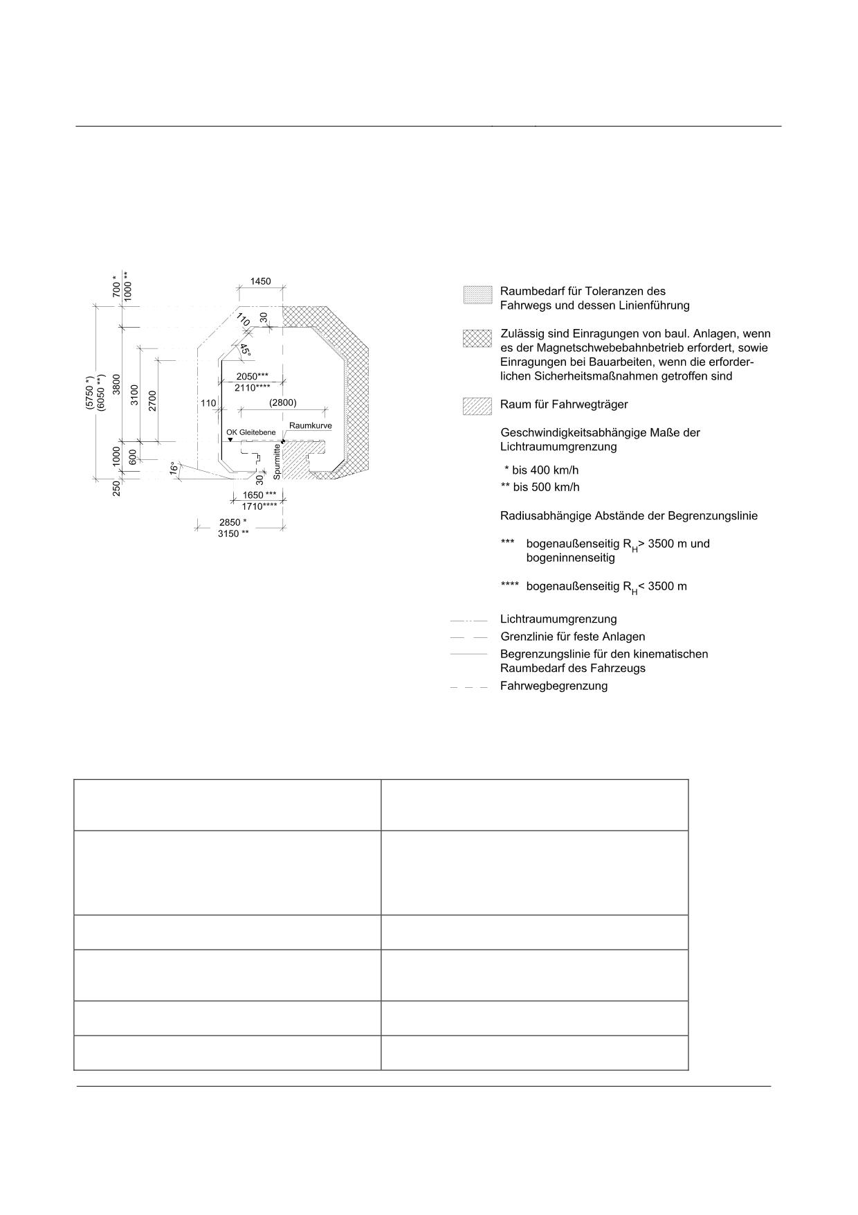
High-speed Maglev system
Maglev Technical Committee
Design principles
Guideway
Clearance and gauges
The figures from the /MbBO/ were used as the basis for Figures 9 to 13 and supplemented by the
lateral tilt area.
Figure 236: Clearance and gauges of the Maglev system single track guideway, α = 0°
Raumbedarf für Toleranzen des Fahrweg…
Space requirement for tolerances of the guideway
and its line layout
Zulässig sind Einragungen ..
The protrusion of structures is permissible if re-
quired by the operation of the high-speed Maglev
system, and protrusions in the case of construction
work, if the required safety measures are taken
Raum für Fahrwegträger
Space for guideway beams
Geschwindigkeitsabhängige Maße …
Speed-dependent dimensions of the clearance
gauge
bis
up to
Radiusabhängige Abstände …
Radius-dependent spacing of gauges
Title
High-speed Maglev system, design principles
Guideway, Part IV, Routing
Doc. No.:
60640
Version White pa-
Issue date
15.02.2007
Page 41
per
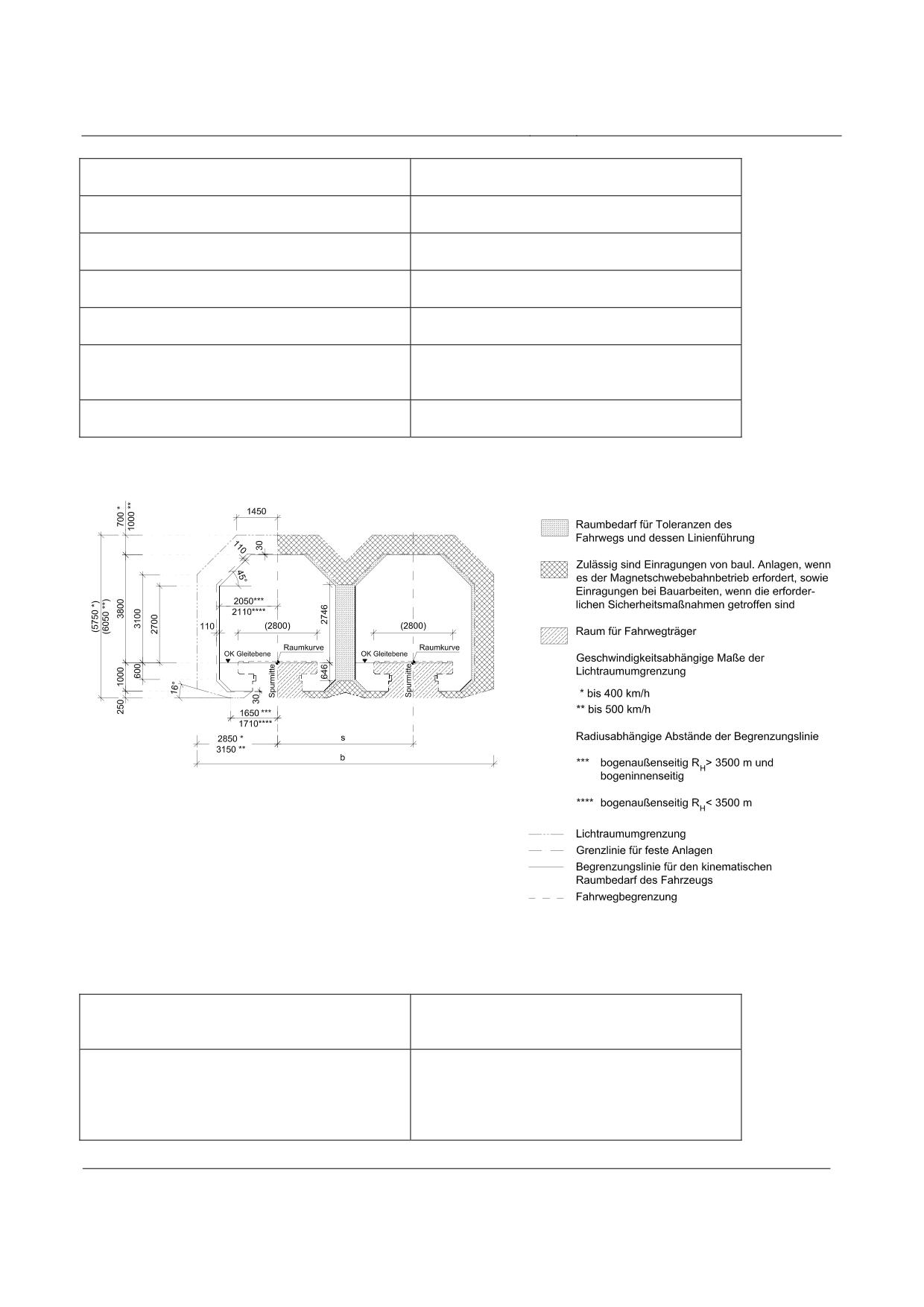
High-speed Maglev system
Maglev Technical Committee
Design principles
Guideway
bogenaußenseitig
Outside of curve
und
and
bogeninnenseitig
Inside of curve
Lichtraumbegrenzung
Clearance limit
Grenzlinie für feste Anlagen
Boundary for fixed structures
Begrenzungslinie für den kinematischen Raumbe-
Gauge for the kinematic space requirement of the
darf des Fahrzeugs
vehicle
Fahrwegbegrenzung
Guideway limit
Figure 237: Clearance and gauges of the Maglev system double track guideway, α = 0°
Raumbedarf für Toleranzen des Fahrweg…
Space requirement for tolerances of the guideway
and its line layout
Zulässig sind Einragungen ..
The protrusion of structures is permissible if re-
quired by the operation of the high-speed Maglev
system, and protrusions in the case of construction
work, if the required safety measures are taken
Title
High-speed Maglev system, design principles
Guideway, Part IV, Routing
Doc. No.:
60640
Version White pa-
Issue date
15.02.2007
Page 42
per
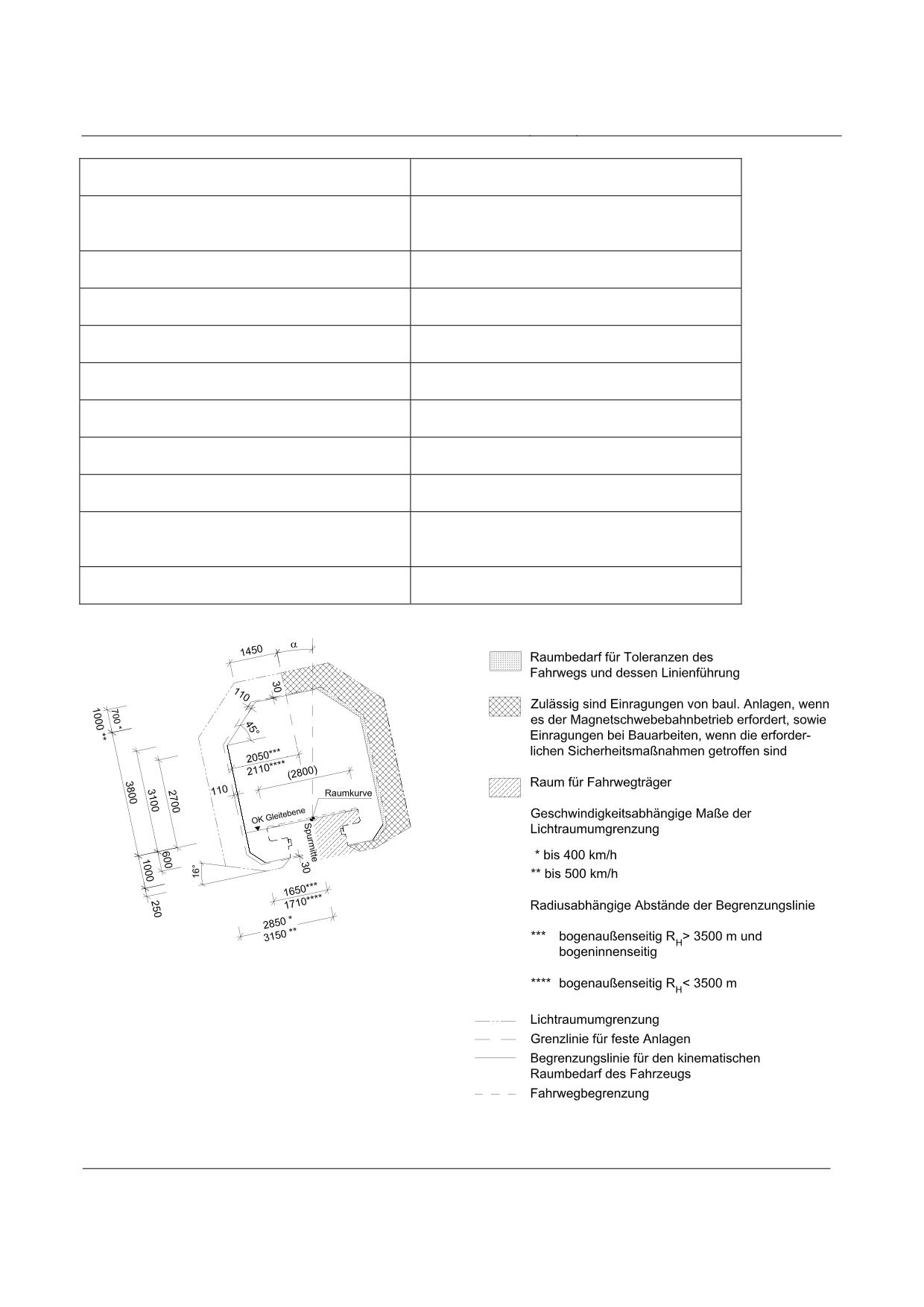
High-speed Maglev system
Maglev Technical Committee
Design principles
Guideway
Raum für Fahrwegträger
Space for guideway beams
Geschwindigkeitsabhängige Maße …
Speed-dependent dimensions of the clearance
gauge
bis
up to
Radiusabhängige Abstände …
Radius-dependent spacing of gauges
bogenaußenseitig
Outside of curve
und
and
bogeninnenseitig
Inside of curve
Lichtraumbegrenzung
Clearance limit
Grenzlinie für feste Anlagen
Boundary for fixed structures
Begrenzungslinie für den kinematischen Raumbe-
Gauge for the kinematic space requirement of the
darf des Fahrzeugs
vehicle
Fahrwegbegrenzung
Guideway limit
Figure 238: Clearance and gauges of the Maglev system single track guideway, α <= 12°
Title
High-speed Maglev system, design principles
Guideway, Part IV, Routing
Doc. No.:
60640
Version White pa-
Issue date
15.02.2007
Page 43
per
High-speed Maglev system
Maglev Technical Committee
Design principles
Guideway
Raumbedarf für Toleranzen des Fahrweg…
Space requirement for tolerances of the guideway
and its line layout
Zulässig sind Einragungen ..
The protrusion of structures is permissible if re-
quired by the operation of the high-speed Maglev
system, and protrusions in the case of construction
work, if the required safety measures are taken
Raum für Fahrwegträger
Space for guideway beams
Geschwindigkeitsabhängige Maße …
Speed-dependent dimensions of the clearance
gauge
bis
up to
Radiusabhängige Abstände …
Radius-dependent spacing of gauges
bogenaußenseitig
Outside of curve
und
and
bogeninnenseitig
Inside of curve
Lichtraumbegrenzung
Clearance limit
Grenzlinie für feste Anlagen
Boundary for fixed structures
Begrenzungslinie für den kinematischen Raumbe-
Gauge for the kinematic space requirement of the
darf des Fahrzeugs
vehicle
Fahrwegbegrenzung
Guideway limit
Title
High-speed Maglev system, design principles
Guideway, Part IV, Routing
Doc. No.:
60640
Version White pa-
Issue date
15.02.2007
Page 44
per
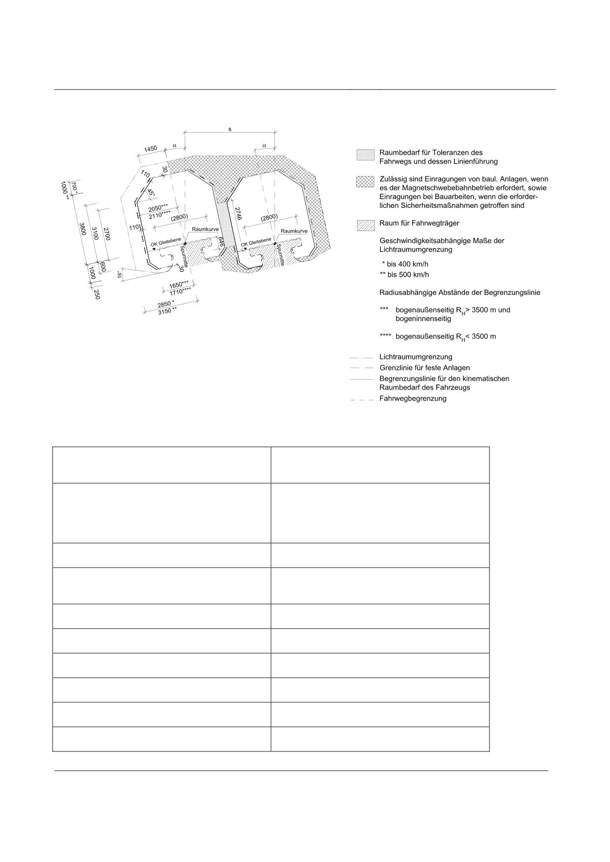
High-speed Maglev system
Maglev Technical Committee
Design principles
Guideway
Figure 239: Clearance and gauges for the Maglev system double track guideway, α ≤ 12°
Raumbedarf für Toleranzen des Fahrweg…
Space requirement for tolerances of the guideway
and its line layout
Zulässig sind Einragungen ..
The protrusion of structures is permissible if re-
quired by the operation of the high-speed Maglev
system, and protrusions in the case of construction
work, if the required safety measures are taken
Raum für Fahrwegträger
Space for guideway beams
Geschwindigkeitsabhängige Maße …
Speed-dependent dimensions of the clearance
gauge
bis
up to
Radiusabhängige Abstände …
Radius-dependent spacing of gauges
bogenaußenseitig
Outside of curve
und
and
bogeninnenseitig
Inside of curve
Lichtraumbegrenzung
Clearance limit
Title
High-speed Maglev system, design principles
Guideway, Part IV, Routing
Doc. No.:
60640
Version White pa-
Issue date
15.02.2007
Page 45
per
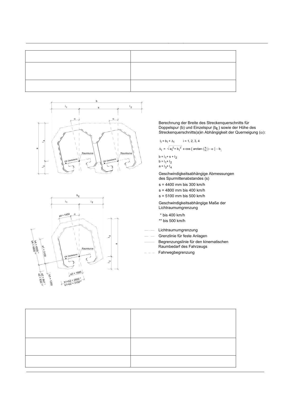
High-speed Maglev system
Maglev Technical Committee
Design principles
Guideway
Grenzlinie für feste Anlagen
Boundary for fixed structures
Begrenzungslinie für den kinematischen Raumbe-
Gauge for the kinematic space requirement of the
darf des Fahrzeugs
vehicle
Fahrwegbegrenzung
Guideway limit
Figure 240: Clearance of the Maglev system in relation to α ≤ 12°
Berechnung der Breite ...
Calculation of the width of the route cross-section
for double track (b) and single track (bE) as well
as the height of the route cross-section (a) in rela-
tion to the lateral tilt (α)
Geschwindigkeitsabhängige Maße …
Speed-dependent dimensions of the clearance
gauge
bis
up to
Title
High-speed Maglev system, design principles
Guideway, Part IV, Routing
Doc. No.:
60640
Version White pa-
Issue date
15.02.2007
Page 46
per
High-speed Maglev system
Maglev Technical Committee
Design principles
Guideway
Lichtraumbegrenzung
Clearance limit
Grenzlinie für feste Anlagen
Boundary for fixed structures
Begrenzungslinie für den kinematischen Raumbe-
Gauge for the kinematic space requirement of the
darf des Fahrzeugs
vehicle
Fahrwegbegrenzung
Guideway limit
Title
High-speed Maglev system, design principles
Guideway, Part IV, Routing
Doc. No.:
60640
Version White pa-
Issue date
15.02.2007
Page 47
per
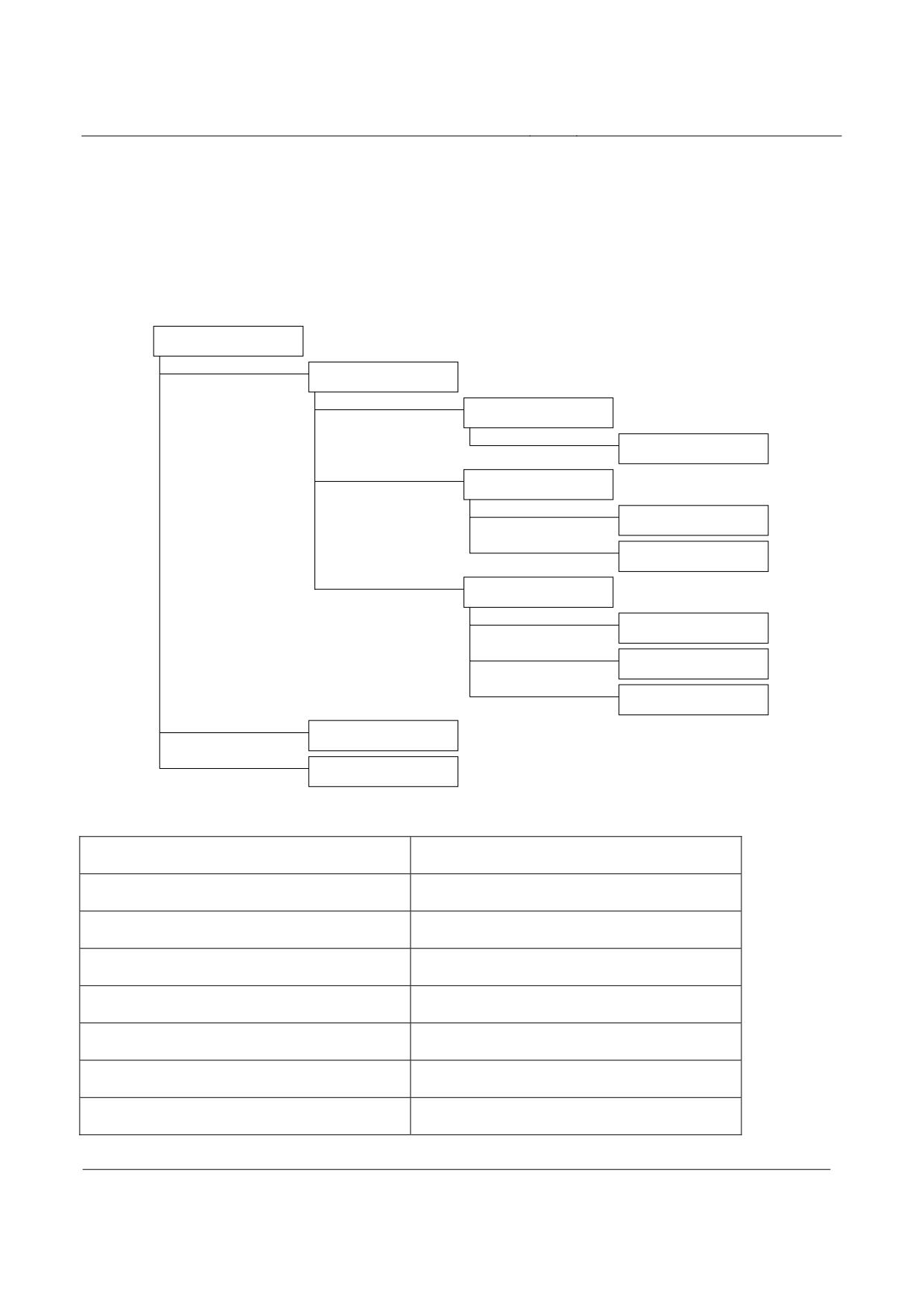
High-speed Maglev system
Maglev Technical Committee
Design principles
Guideway
Track switching equipment
General
Figure 241 shows the current variants of track switching equipment.
Spurwechseleinrichtungen
Weichen
Schnellfahrweichen
2 - Wege - SFW
Langsamfahrweichen
2 - Wege - LFW
3 - Wege - LFW
Überleitstelle
mit 2 - Wege - SFW
mit 2 - Wege - LFW
X-Überleitverbindung mit
Spurmitenabstand 5,10 m
Schiebebühne
Schwenkbühne
Figure 241: Classification of track switching devices
Spurwechseleinrichtungen
Line changing devices
Weichen
Switches
Schnellfahrweichen
High-speed switches
2-Wege SFW
2-way HSS
Langsamfahrweiche
Low-speed switches
2-Wege LFW
2-way LSS
3-Wege LFW
3-way LSS
Überleitstelle
Cross-over
Title
High-speed Maglev system, design principles
Guideway, Part IV, Routing
Doc. No.:
60640
Version White pa-
Issue date
15.02.2007
Page 48
per
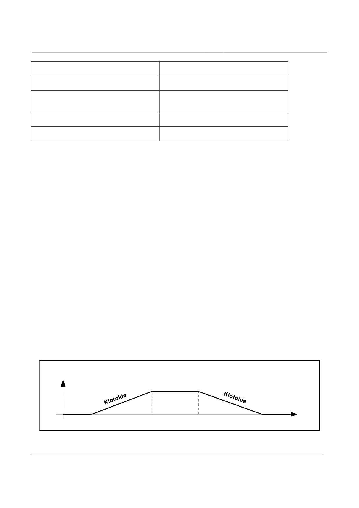
High-speed Maglev system
Maglev Technical Committee
Design principles
Guideway
mit 2-Wege SFW
With 2-way HSS
mit 2-Wege LFW
With 2-way LSS
X-Überleitverbindung mit Spurmittenabstand 5.10
X-connection with guideway pitch 5.10 m
m
Schiebebühne
Travelling platform
Schwenkbühne
Swinging platform
Switches
General
The following principles should be observed for the layout of switches:
• The entire switch support can be bent from the straight position to the turnout position.
• In the ground plan the geometric sequence is as follows: straight-clotoid-circle-clotoid-
straight. This sequence largely approximates the bending line of the switch support.
Figure 11 shows the elements of the curve band of a switch in the turnout position.
• For reasons of comfort it is recommended that a straight section (RH = ∞) be included in
the layout of the turnout track behind a switch for the travel time of 2 seconds.
This recommendation does not apply for connections, since in this case a second switch is
negotiated immediately after the first.
• In the gradient only the radius RV = ∞ is permissible.
• The planned lateral tilt of the switch is 0°.
• The planned longitudinal tilt of the switch is up to 100 ‰.
If a longitudinal tilt not equal to 0 ‰ is used route elements not mathematically defined in
the ground plan of the turnout position occur.
K = 1/RH
K
Kreis
RH = ∞
RH = ∞
L
Figure 242: Curve band for switch
Title
High-speed Maglev system, design principles
Guideway, Part IV, Routing
Doc. No.:
60640
Version White pa-
Issue date
15.02.2007
Page 49
per
High-speed Maglev system
Maglev Technical Committee
Design principles
Guideway
Klotoide
Clotoid
Kreis
Circle
Design examples of switch
Currently known design examples are shown below. Further switches can be defined on a project-
specific basis.
The design examples include the geometric sequence of the route elements and a table containing
the permissible speeds and the resulting lateral acceleration and lateral jerk values.
The title “medium-section / long-section application” and “regional application” arose due to the
vehicle design (sitting passengers / standing passengers).
The values for the “regional application” should be taken as a recommendation.
The recommendations given in the following tables for regional applications are based upon com-
fort investigations focussing upon standing passengers.
Connections consist of 2 bendable switches and a locking device.
X-connections consist of 4 bendable switches, the guideway pitch is 5.100 m. In the turnout position
it is necessary to set even the non-negotiated bendable switch in the turnout position, as otherwise
the gauge for fixed installations would be exceeded (Chapter 0).
Title
High-speed Maglev system, design principles
Guideway, Part IV, Routing
Doc. No.:
60640
Version White pa-
Issue date
15.02.2007
Page 50
per
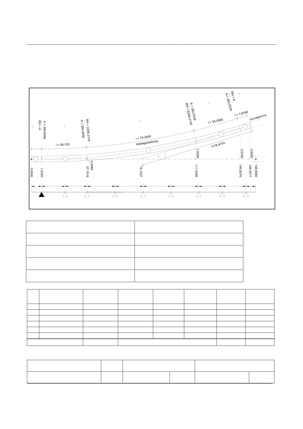
High-speed Maglev system
Maglev Technical Committee
Design principles
Guideway
High-speed switch
The route elements of the high-speed switch are shown in Figure 12 in ground-plan form and not to
scale, and are listed in Table 3.
The driving dynamic values for this switch are listed in Table 4.
5
4
3
1
2
5
4
l= 1,0320
3
Verriegelung
1
2
Geradeausstellung
1,0320
17,5440
18,5760
18,5760
18,5760
18,5760
18,5760
18,5760
16,9600
1,6160
Stütze 0
Stütze 1
Stütze 2
Stütze 3
Stütze 4
Stütze 5
Stütze 6
Stütze 7
Stütze 8
Festlager
Figure 243: Route elements for high-speed switch (design example)
Verriegelung
Lock
Abbiegestellung
Turnout position
Geradeausstellung
Straight position
Stütze
Support
Festlager
Fixed bearing
No.
Element
Length
Radius
Abscissa
Ordinate
τ
τ
[m]
[m]
[m]
[m]
[gon]
[°]
WA
0.0000
0.0000
0,00000
0,00000
1
Straight
1.0320
1.0320
0.0000
0,00000
0,00000
2
Clotoid
36.1200
37.1518
0.0968
0,51183
0,46065
3
Arc
74.3040
-2246.3179
111.4299
1.9228
2,10582
1,89524
4
Clotoid
35.5360
146.9276
3.5708
0,50356
0,45320
5
Straight
1.6160
148.5417
3.6500
0,00000
0,00000
∑
148.6080
3.12121
2.80909
Table 146:
Route parameters for high-speed switch (design example)
Variable
Medium section application /
Regional application
Long section application
(Recommendation)
Permissible speed
vmax
500
[km/h]
500
[km/h]
straight position
Title
High-speed Maglev system, design principles
Guideway, Part IV, Routing
Doc. No.:
60640
Version White pa-
Issue date
15.02.2007
Page 51
per
High-speed Maglev system
Maglev Technical Committee
Design principles
Guideway
Permissible speed
vmax
195
[km/h]
155
[km/h]
turnout position
Uncompensated
ay
1.31
[m/s²]
0.83
[m/s²]
lateral acceleration
Lateral jerk
åy
1.96 / 1.99
[m/s3]
0.98 / 1.00
[m/s3]
(1st / 2nd clotoid)
Table 147: Driving dynamic values for high-speed switch (design example)
Title
High-speed Maglev system, design principles
Guideway, Part IV, Routing
Doc. No.:
60640
Version White pa-
Issue date
15.02.2007
Page 52
per
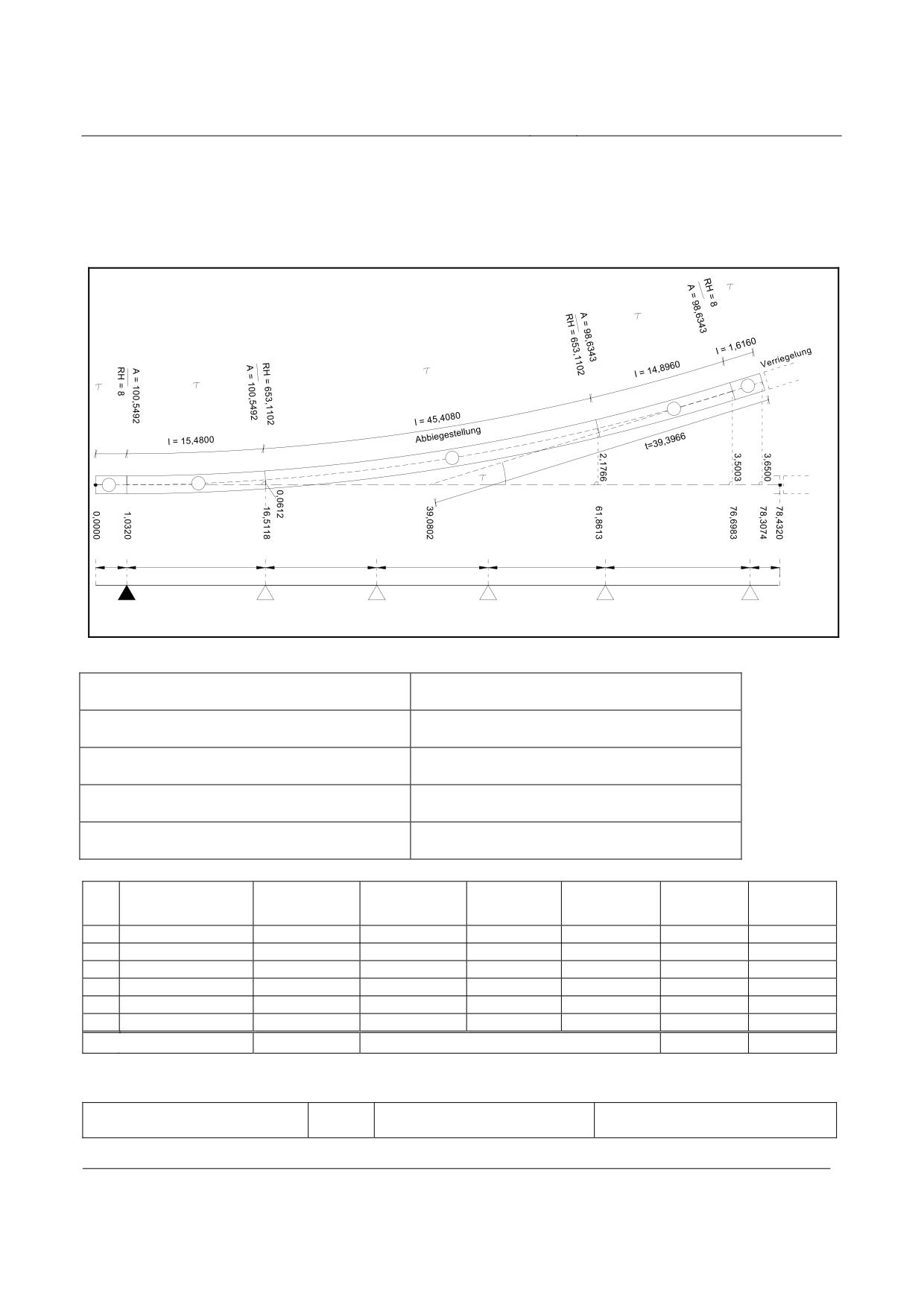
High-speed Maglev system
Maglev Technical Committee
Design principles
Guideway
Low-speed switch
The route elements of the low-speed switch are shown in Figure 13 in ground plan form and not to
scale, and are listed in Table 5.
The driving dynamic values for this switch are listed in Table 6.
5
4
3
1
2
5
4
l= 1,0320
3
Verriegelung
1
2
Geradeausstellung
1,0320
15,4800
14,4480
16,5120
14,4480
14,8960
1,6160
Stütze 0
Stütze 1
Stütze 2
Stütze 3
Stütze 4
Stütze 5
Festlager
Figure 244: Route elements for 2-way low-speed switch (design example)
Verriegelung
Lock
Abbiegestellung
Turnout position
Geradeausstellung
Straight position
Stütze
Support
Festlager
Fixed bearing
No.
Element
Length
Radius
Abscissa
Ordinate
τ
τ
[m]
[m]
[m]
[m]
[gon]
[°]
WA
0.0000
0.0000
0.00000
0,00000
1
Straight
1.0320
1.0320
0.0000
0.00000
0,00000
2
Clotoid
15.4800
16.5118
0.0612
0.75446
0,67901
3
Arc
45.4080
-653.1102
61.8613
2.1766
4.42615
3,98354
4
Clotoid
14.8960
76.6983
3.5003
0.72599
0,65339
5
Straight
1.6160
78.3074
3.6500
0.00000
0,00000
∑
78.4320
5.90660
5.31594
Table 148:
Route parameters for 2-way low-speed switch (design example)
Size
Medium section application /
Regional application
Long section application
(Recommendation)
Title
High-speed Maglev system, design principles
Guideway, Part IV, Routing
Doc. No.:
60640
Version White pa-
Issue date
15.02.2007
Page 53
per
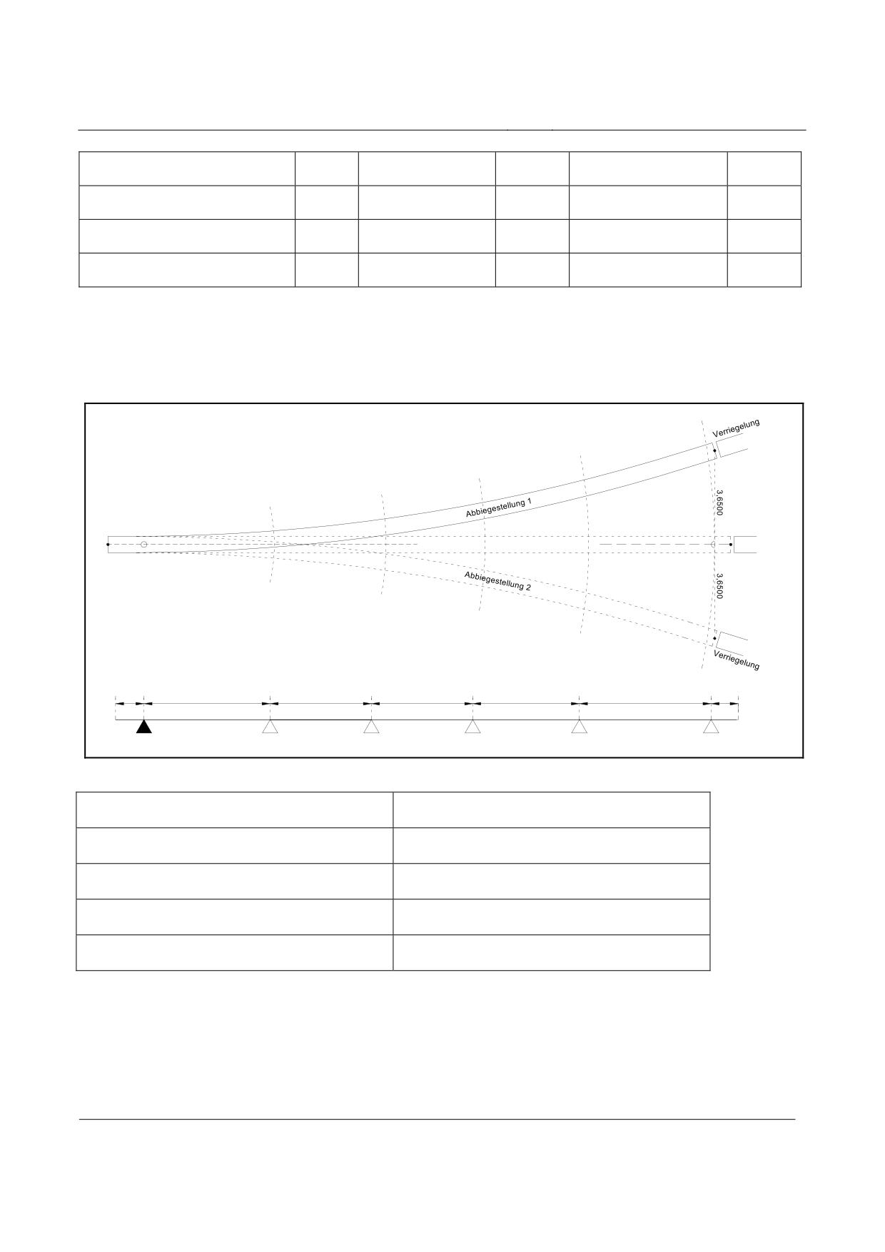
High-speed Maglev system
Maglev Technical Committee
Design principles
Guideway
Permissible speed
vmax
500
[km/h]
500
[km/h]
straight position
Permissible speed
vmax
97
[km/h]
77
[km/h]
turnout position
Uncompensated
ay
1.10
[m/s²]
0.69
[m/s²]
lateral acceleration
Lateral jerk
åy
1.91 / 1.98
[m/s3]
0.95 / 0.99
[m/s3]
(1st / 2nd clotoid)
Table 149: Driving dynamic values of the 2-way low-speed switch (design example)
The geometric dimensions of the 3-way low-speed switch correspond to those of the 2-way low-
speed switch (see Figure 244 and Table 148) with the straight direction as the axis of symmetry.
Figure 245 shows the position variants.
Verriegelung
Geradeausstellung
1,0320
15,4800
14,4480
16,5120
14,4480
14,8960
1,6160
Stütze 0
Stütze 1
Stütze 2
Stütze 3
Stütze 4
Stütze 5
Festlager
Figure 245: Position variants of the 3-way low-speed switch (design example)
Verriegelung
Lock
Abbiegestellung
Turnout position
Geradeausstellung
Straight position
Stütze
Support
Festlager
Fixed bearing
Title
High-speed Maglev system, design principles
Guideway, Part IV, Routing
Doc. No.:
60640
Version White pa-
Issue date
15.02.2007
Page 54
per
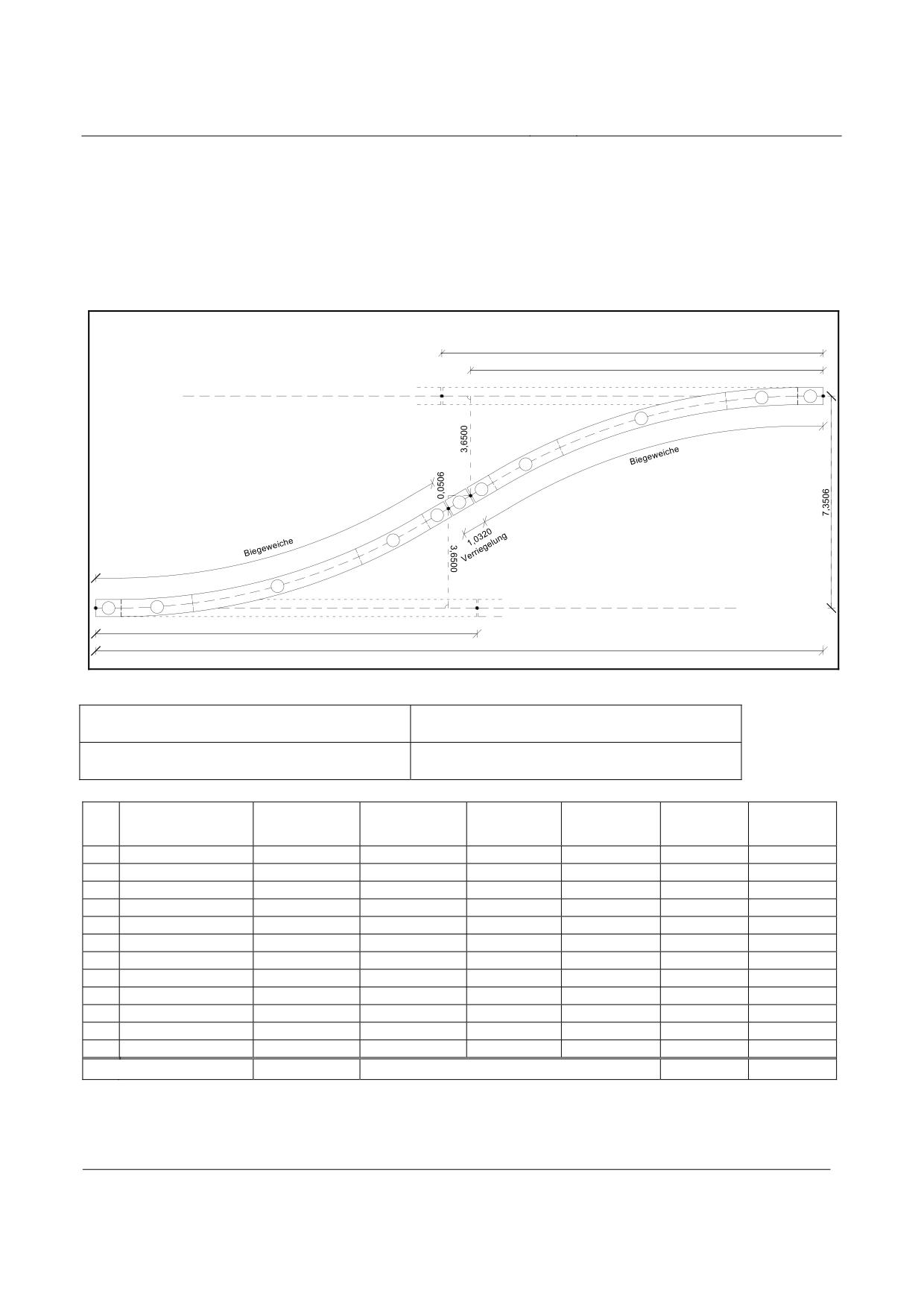
High-speed Maglev system
Maglev Technical Committee
Design principles
Guideway
Connection with high-speed switch
Connections between tracks running in parallel are produced by the combination of several ben-
dable switches.
Figure 246 shows the sequence of route elements for a connection with high-speed switches, depic-
tion is not to scale, Table 150 shows the route elements.
Table 151 contains the driving dynamic values for this connection.
l = 148,6080
148,5418
10
11
Verriegelung
9
1,0308
8
7
6
5
4
3
Verriegelung
1
2
l = 148,6080
l = 298,1144
Figure 246:
Route elements for the connection with high-speed switches (design example)
Verriegelung
Lock
Biegeweiche
Bendable switch
No.
Element
Length
Radius
Abscissa
Ordinate
τ
τ
[m]
[m]
[m]
[m]
[gon]
[°]
WA
0.0000
0.0000
0,00000
0,00000
1
Straight
0.5000
0.5000
0.0000
0,00000
0,00000
2
Clotoid
36.6520
37.1518
0.0992
0,51687
0,46518
3
Arc
74.3040
-2257.1800
111.4300
1.9252
2,09569
1,88612
4
Clotoid
36.0680
147.4591
3.5969
0,50863
0,45777
5
Straight
1.0840
148.5418
3.6500
0,00000
0,00000
6
Straight
0.5000
149.5726
3.7006
0,00000
0,00000
7
Straight
1.0840
150.6553
3.7537
0,00000
0,00000
8
Clotoid
36.0680
186.6844
5.4254
-0,50863
-0,45777
9
Arc
74.3040
+2257.1800
260.9626
7.2514
-2,09569
-1,88612
10
Clotoid
36.6520
297.6144
7.3506
-0,51687
-0,46518
11
Straight
0.5000
298.1144
7.3506
0,00000
0,00000
∑
298.248
0.00000
0.00000
Table 150: Route parameters for the connection with high-speed switches (design example)
Title
High-speed Maglev system, design principles
Guideway, Part IV, Routing
Doc. No.:
60640
Version White pa-
Issue date
15.02.2007
Page 55
per

High-speed Maglev system
Maglev Technical Committee
Design principles
Guideway
Variable
Medium section application /
Regional application
Long section application
(Recommendation)
Permissible speed
vmax
500
[km/h]
500
[km/h]
straight position
Permissible speed
vmax
196
[km/h]
124
[km/h]
turnout position
Uncompensated
ay
1.31
[m/s²]
0.53
[m/s²]
lateral acceleration
Lateral jerk
åy
1.95 / 1.98
[m/s3]
0.49 / 0.50
[m/s3]
(1st / 2nd clotoid)
Table 151: Driving dynamic values of the connection with high-speed switches (design example)
Title
High-speed Maglev system, design principles
Guideway, Part IV, Routing
Doc. No.:
60640
Version White pa-
Issue date
15.02.2007
Page 56
per
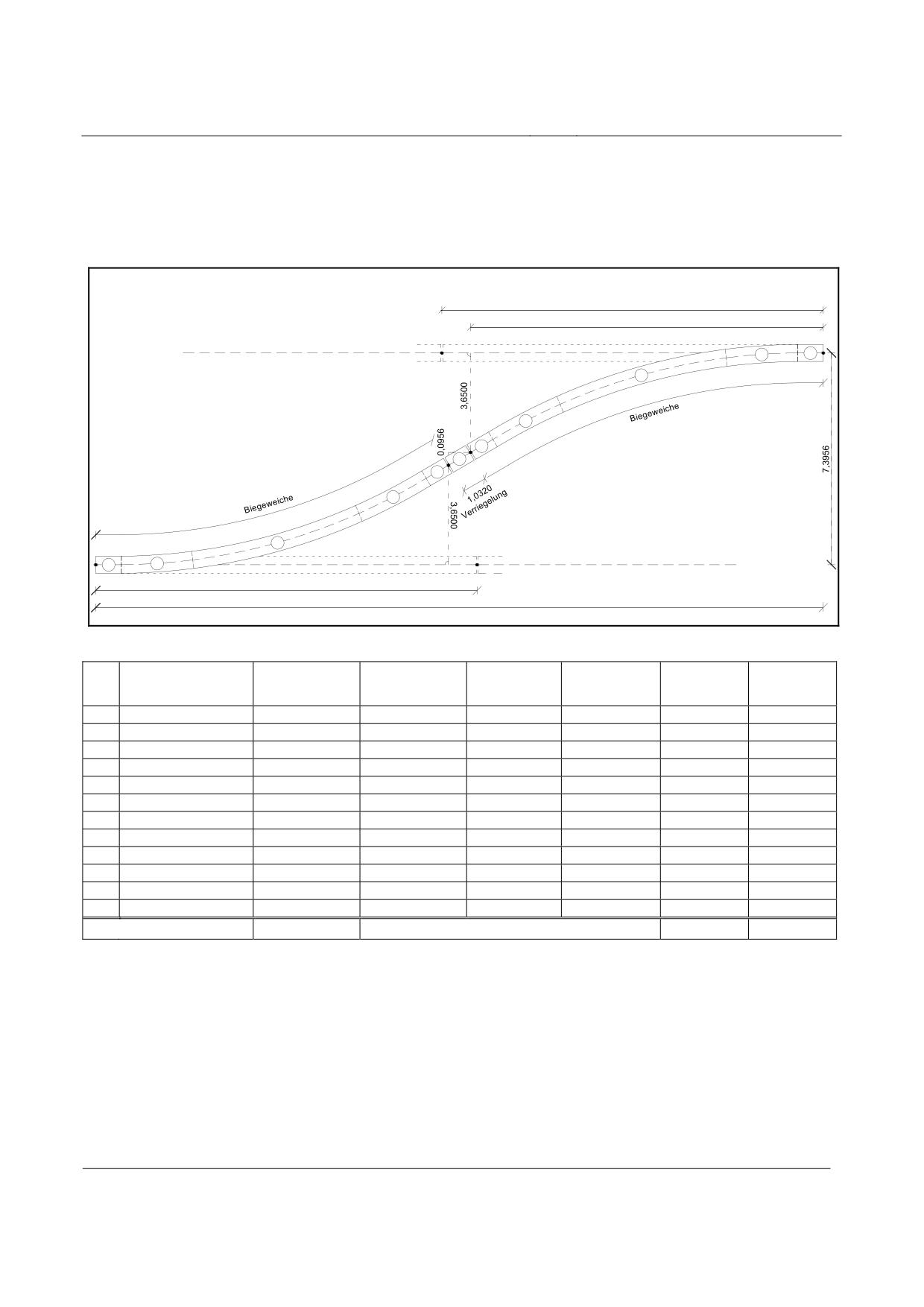
High-speed Maglev system
Maglev Technical Committee
Design principles
Guideway
Connection with low-speed switch
Figure 247 shows the routing sequence for a connection with low-speed switches, depiction is not
to scale, Table 152 shows the route elements.
Table 153 contains the driving dynamic values for this connection.
l= 78,4320
78,3074
10
11
Verriegelung
9
1,0275
8
7
6
5
4
3
Verriegelung
1
2
l = 78,4320
l = 157,6423
Figure 247:
Route elements of the connection with low-speed switches (design example)
No.
Element
Length
Radius
Abscissa
Ordinate
τ
τ
[m]
[m]
[m]
[m]
[gon]
[°]
WA
0.0000
0.0000
0,00000
0,00000
1
Straight
1.0320
1.0320
0.0000
0,00000
0,00000
2
Clotoid
15.4800
16.5118
0.0612
0,75446
0,67901
3
Arc
45.4080
-653.1102
61.8613
2.1766
4,42615
3,98354
4
Clotoid
14.8960
76.6983
3.5003
0,72599
0,65339
5
Straight
1.6160
78.3074
3.6500
0,00000
0,00000
6
Straight
1.0320
79.3349
3.7456
0,00000
0,00000
7
Straight
1.6160
80.9440
3.8953
0,00000
0,00000
8
Clotoid
14.8960
95.7810
5.2190
-0.72599
-0,65339
9
Arc
45.4080
+653.1102
141.1305
7.3345
-4.42615
3,98354
10
Clotoid
15.4800
156.6103
7.3956
-0.75446
-0,67901
11
Straight
1.0320
157.6423
7.3956
0.00000
0,00000
∑
157.8960
0.00000
0.00000
Table 152: Route parameters of the connection with low-speed switches (design example)
Title
High-speed Maglev system, design principles
Guideway, Part IV, Routing
Doc. No.:
60640
Version White pa-
Issue date
15.02.2007
Page 57
per
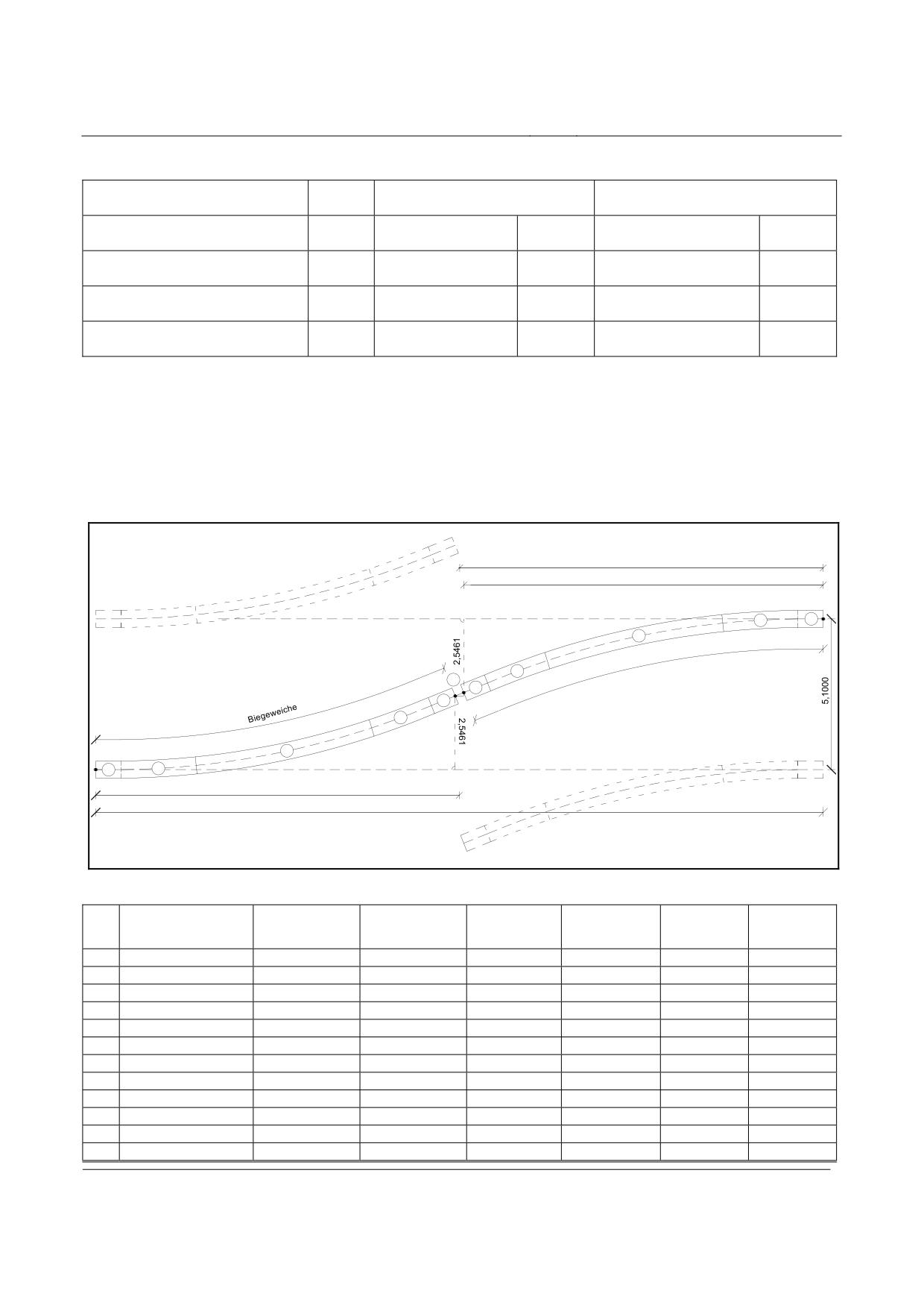
High-speed Maglev system
Maglev Technical Committee
Design principles
Guideway
Variable
Medium section application /
Regional application
Long section application
(Recommendation)
Permissible speed
vmax
500
[km/h]
500
[km/h]
straight position
Permissible speed
vmax
97
[km/h]
61
[km/h]
turnout position
Uncompensated
ay
1.10
[m/s²]
0.44
[m/s²]
lateral acceleration
Lateral jerk
åy
1.91 / 1.98
[m/s3]
0.47 / 0.49
[m/s3]
(1st / 2nd clotoid)
Table 153: Driving dynamic values of the connection with low-speed switches (design example)
X-connection with low-speed switches for a guideway pitch of 5.10 m
The arrangement of low-speed switches into an X-connection with a guideway pitch of 5.10 m can
be routed as a space saving variant (Figure 248, Table 154, Table 155).
The open ends of the straight tracks must be turned outwards at the connection in order to maintain
the required clearances.
l = 78,4320
78,3714
10
11
9
8
6
7
5
4
3
1
2
l = 78,4320
l = 156,8640
Figure 148: X-connection with low-speed switches (guideway pitch 5.10 m) (design example)
No.
Element
Length
Radius
Abscissa
Ordinate
τ
τ
[m]
[m]
[m]
[m]
[gon]
[°]
WA
0,0000
0,0000
0.00000
0.00000
1
Straight
1.0320
1.0320
0.0000
0.00000
0.00000
2
Clotoid
15.4800
16.5119
0.0426
0.52604
0.47344
3
Arc
45.4080
-936.7000
61.8915
1.5181
3.08612
2.77751
4
Clotoid
14.8960
76.7588
2.4416
0.50619
0.45557
5
Straight
1.6160
78.3714
2.5461
0.00000
0.00000
6
geom. gap
0.1216
78.4926
2.5539
0.00000
0.00000
7
Straight
1.6160
80.1053
2.6584
0.00000
0.00000
8
Clotoid
14.8960
94.9726
3.5820
-0.50619
-0.45557
9
Arc
45.4080
+936.7000
140.3521
5.0574
-3.08612
-2.77751
10
Clotoid
15.4800
155.8320
5.1000
-0.52604
-0.47344
11
Straight
1.0320
156.8640
5.1000
0.00000
0.00000
Title
High-speed Maglev system, design principles
Guideway, Part IV, Routing
Doc. No.:
60640
Version White pa-
Issue date
15.02.2007
Page 58
per
High-speed Maglev system
Maglev Technical Committee
Design principles
Guideway
∑
157.8960
0.00000
0.00000
Table 154: Route parameters of the X-connection with low-speed switches (guideway pitch 5.10 m) (design example)
Title
High-speed Maglev system, design principles
Guideway, Part IV, Routing
Doc. No.:
60640
Version White pa-
Issue date
15.02.2007
Page 59
per

High-speed Maglev system
Maglev Technical Committee
Design principles
Guideway
Variable
Medium section application /
Regional application
Long section application
(Recommendation)
Permissible speed
vmax
500
[km/h]
500
[km/h]
straight position
Permissible speed
vmax
109
[km/h]
69
[km/h]
turnout position
Uncompensated
ay
1.98
[m/s²]
0.39
[m/s²]
lateral acceleration
Lateral jerk
åy
1.91 / 1.98
[m/s3]
0.47 / 0.50
[m/s3]
(1st / 2nd clotoid)
Table 155: Driving dynamic values of the X-connection with low-speed switches (guideway pitch 5.10 m) (design ex-
ample)
Title
High-speed Maglev system, design principles
Guideway, Part IV, Routing
Doc. No.:
60640
Version White pa-
Issue date
15.02.2007
Page 60
per
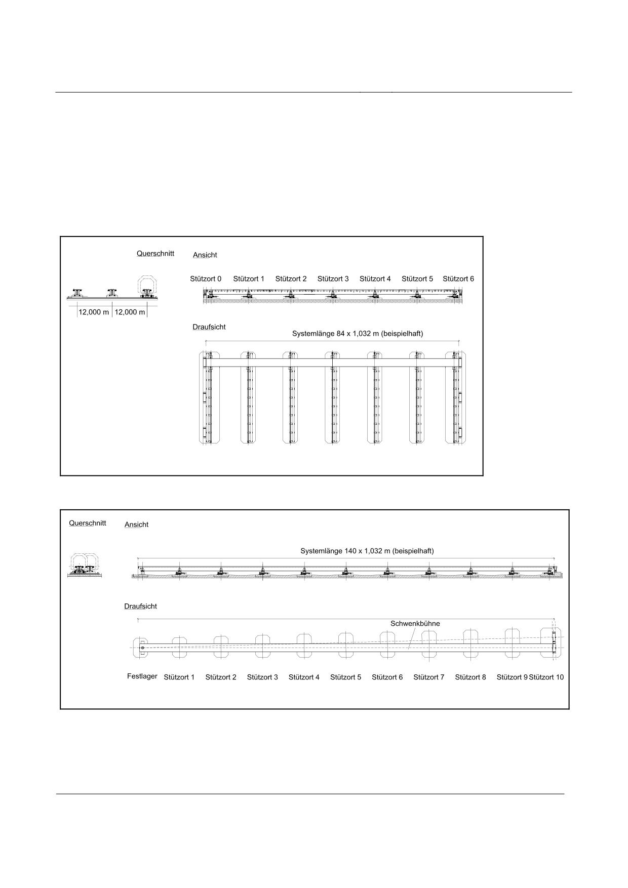
High-speed Maglev system
Maglev Technical Committee
Design principles
Guideway
Travelling platform and swinging platform
The travelling platform (Figure 249) and the swinging platform (Figure 250) are routed as straight
track (RH = ∞) in the ground plan.
In the gradient path, depiction as hump or valley is possible.
The travelling platform and the swinging platform are moved while the vehicle is stationary. Ac-
cording to Chapter Error! Reference source not found. slopes should not be used.
Figure 249: Travelling platform (example)
Figure 250: Swinging platform (example)
Title
High-speed Maglev system, design principles
Guideway, Part IV, Routing
Doc. No.:
60640
Version White pa-
Issue date
15.02.2007
Page 61
per
High-speed Maglev system
Maglev Technical Committee
Design principles
Guideway
Operations facilities
Operations facilities such as stations or maintenance facilities will be designed on a project-
specific basis.
They are therefore not part of these design principles for the layout of high-speed Maglev guide-
ways.
The routing limit values given in this document however also apply for the operations facilities.
Within operations facilities, clotoids in the form of transition curves can be used as route elements
in the ground plan under the above-mentioned conditions.
If a platform is planned between the guideways of a laterally tilted double track, the height differen-
ce between the entry levels should be compensated by parallel height adjustment of the gradients, so
that the platform can run horizontally in the transverse direction.
Title
High-speed Maglev system, design principles
Guideway, Part IV, Routing
Doc. No.:
60640
Version White pa-
Issue date
15.02.2007
Page 62
per
High-speed Maglev system
Maglev Technical Committee
Design principles
Guideway
High-speed Maglev System
Design Principles
Guideway
Part V
Surveying
The copyright to this document and all appendices remains the property of the creator.
All rights reserved
Title
High-speed Maglev system, design principles
Guideway, Part V, Surveying
Doc. No.:
60641
Version White pa-
Issue date
15.02.2007
Page 1
per
High-speed Maglev system
Maglev Technical Committee
Design principles
Guideway
Distributor
This document was released for publication by the ‘Guideway’ committee of experts.
Title
High-speed Maglev system, design principles
Guideway, Part V, Surveying
Doc. No.:
60641
Version White pa-
Issue date
15.02.2007
Page 2
per
High-speed Maglev system
Maglev Technical Committee
Design principles
Guideway
Overview of revisions
Date of release: 15.02.2007, currently valid version, ‘Guideway’ committee of experts.
Title
High-speed Maglev system, design principles
Guideway, Part V, Surveying
Doc. No.:
60641
Version White pa-
Issue date
15.02.2007
Page 3
per
High-speed Maglev system
Maglev Technical Committee
Design principles
Guideway
Table of Contents
Driving dynamic specifications
24
Target line speed and permissible line speed
24
Accelerations
25
Drive and braking acceleration
26
Uncompensated lateral acceleration
26
Normal acceleration (comfort value)
28
Jerks
29
Lateral jerk
30
Vertical jerk
31
Longitudinal jerk
32
Omnidirectional jerk
32
Minimum length of sinusoid
33
Minimum length of clotoid
34
Comfort criteria in relation to the overall journey time for the routed section
35
Support division and field widths
38
Single guideway
38
Double or multiple guideway
39
Guideway pitch and clearance
40
Guideway pitch
40
Accuracy
40
Non-parallelism of sinusoids
40
Clearance and gauges
41
Line changing devices
48
General
48
Switches
49
General
49
Design examples of switch
50
High-speed switch
51
Low-speed switch
53
Connection with high-speed switch
55
Connection with low-speed switch
57
X-connection with low-speed switches for a guideway pitch of 5.10 m
58
Travelling platform and swinging platform
61
Operations facilities
62
Title
High-speed Maglev system, design principles
Guideway, Part V, Surveying
Doc. No.:
60641
Version White pa-
Issue date
15.02.2007
Page 4
per
High-speed Maglev system
Maglev Technical Committee
Design principles
Guideway
Distributor
2
Overview of revisions
3
Table of Contents
4
General
9
Purpose and field of application
9
High-speed Maglev system - design principles
9
Abbreviations and definitions
9
Laws, decrees, standards and directives
9
Identification and binding nature of requirements
10
System of co-ordinates
11
National co-ordinate systems
11
High-speed Maglev co-ordinate system (MCS)
11
Beam production co-ordinate system (BPC)
12
Three-dimensional curve co-ordinate system (TCC)
12
Requirements of the high-speed Maglev co-ordinate system (MCS)
13
Properties
13
Determination of the positional components
13
Projection and transformation
16
Height component
17
Realisation
17
Higher-level fixed point network of the MCS
19
Position determination
19
Height determination
20
Marking out
21
Transformation of the planning system in MCS
23
Route-related fixed-point network in the MCS
24
Position determination
25
Height determination
26
Detailed positioning of the guideway beams
27
Documentation
30
Annex V-A Gauß-Krüger co-ordinate system
31
Annex V-B Universal, transversal mecator projection
33
Distributor
2
Overview of revisions
3
Table of contents
4
Title
High-speed Maglev system, design principles
Guideway, Part V, Surveying
Doc. No.:
60641
Version White pa-
Issue date
15.02.2007
Page 5
per
High-speed Maglev system
Maglev Technical Committee
Design principles
Guideway
General
6
Purpose and field of application
6
Design principles for high-speed Maglev systems
6
Abbreviations and definitions
7
Laws, decrees, standards and directives
7
Identification and binding nature of requirements
7
Requirements regarding guideway maintenance
8
Basic principles
8
Specifications and recommendations for the maintenance strategy
9
Specifications
9
Recommendations
10
Requirements relating to personnel
10
Servicing
11
Inspections
12
General requirements relating to inspections
12
Monitoring
12
Investigations
13
Appraisals
14
Special inspections
14
Maintenance
16
Other measures
17
Requirements regarding the sequences of maintenance processes
18
Technical notes on the performance of inspections
20
Possibilities for monitoring
20
Degree of automation of the inspections
20
Inspection of the geometry
20
Visual inspections
21
Inspection by means of stationary measuring devices
21
Other inspections
21
Fundamental requirements regarding documentation
22
Title
High-speed Maglev system, design principles
Guideway, Part V, Surveying
Doc. No.:
60641
Version White pa-
Issue date
15.02.2007
Page 6
per
High-speed Maglev system
Maglev Technical Committee
Design principles
Guideway
Table of figures
Figure 1: Sign of accelerations
25
Figure 2: Ride comfort for longitudinal and lateral acceleration (according to ISO 2631)
36
Figure 3: Ride comfort - normal acceleration (according to ISO 2631)
37
Figure 4: Three-dimensional curve lengths in the case of multiple guideway
39
Figure 5: Clearance and gauges of the Maglev system single guideway, α = 0°
41
Figure 6: Clearance and gauges of the Maglev system double guideway, α = 0°
42
Figure 7: Clearance and gauges of the Maglev system single guideway, α <= 12°
43
Figure 8: Clearance and gauges for the Maglev system double guideway, α ≤ 12°
45
Figure 9: Clearance of the Maglev system in relation to α ≤ 12°
46
Figure 10: Classification of line changing devices
48
Figure 11: Curve band for switch
49
Figure 12: Route elements for high-speed switch (design example)
51
Figure 13: Route elements for 2-way low-speed switch (design example)
53
Figure 14: Position variants of the 3-way low-speed switch (design example)
54
Figure 15: Route elements for the connection with high-speed switches (design example)
55
Figure 16: Route elements of the connection with low-speed switches (design example)
57
Figure 17: X-connection with low-speed switches (guideway pitch 5.10 m) (design example)
58
Figure 18: Travelling platform (example)
61
Figure 19: Swinging platform (example)
61
Figure 20: Parameter representation of the high-speed Maglev co-ordinate system
14
Figure 21: Lateral limitation of the MCS
15
Figure 22: Examples of the design of fixed-point marking out
21
Figure 23: Recommended layout accompanying fixed-point field
24
Figure 24: Requirements of the fine positioning of the guideway beams
27
Figure 25: Scale distortion in the Gauß-Krüger system
31
Figure 26: Scale distortion in the UTM system
33
Table of tables
Table 1: Direction of excess and deficient acceleration
27
Table 2: Guideway pitch
40
Table 3: Route parameters for high-speed switch (design example)
51
Table 4: Driving dynamic values for high-speed switch (design example)
52
Table 5: Route parameters for 2-way low-speed switch (design example)
53
Table 6: Driving dynamic values of the 2-way low-speed switch (design example)
54
Table 7: Route parameters for the connection with high-speed switches (design example)
55
Table 8: Driving dynamic values of the connection with high-speed switches (design example) 56
Title
High-speed Maglev system, design principles
Guideway, Part V, Surveying
Doc. No.:
60641
Version White pa-
Issue date
15.02.2007
Page 7
per
High-speed Maglev system
Maglev Technical Committee
Design principles
Guideway
Table 9: Route parameters of the connection with low-speed switches (design example)
57
Table 10: Driving dynamic values of the connection with low-speed switches (design example) 58
Table 11: Route parameters of the X-connection with low-speed switches (guideway
pitch 5.10 m) (design example)
59
Tabelle 12: Driving dynamic values of the X-connection with low-speed switches (guideway
pitch 5.10 m) (design example)
60
Table 13: Depiction distortions
15
Title
High-speed Maglev system, design principles
Guideway, Part V, Surveying
Doc. No.:
60641
Version White pa-
Issue date
15.02.2007
Page 8
per
High-speed Maglev system
Maglev Technical Committee
Design principles
Guideway
General
Purpose and field of application
This document specifies the requirements for the surveying of high-speed Maglev systems. The
network of fixed points (position and height) to be created from it forms the basis for the planning,
construction and the monitoring based on surveying technology during the maintenance of high-
speed Maglev guideways.
These design principles apply independently of projects and serve as the basis for further surveying
and calculation concepts.
Supplementary to this, to improve clarity in this document, explanations and justifications will be
provided regarding the surveying and calculation procedures.
These design principles apply for a high-speed Maglev system in accordance with the Allgemeinem
Magnetschwebebahngesetzt /AMbG/ (General Magnetic Levitation Systems Act).
High-speed Maglev system - design principles
This document is part of the documentation for high-speed Maglev systems consisting of several
design principles. The document tree is shown in Figure 1 /MSB AG-GESAMTSYS/.
The higher-level document Design principles, complete system and its appendices apply consis-
tently for the entire documentation:
• High-speed Maglev system - design principles, complete system, doc. no.: 50630,
/MSB AG-GESAMTSYS/ with the appendices:
• Annex 1: Abbreviations and definitions, doc. no.: 67536, /MSB AG-ABK&DEF/
• Annex 2: Laws, regulations, standards and directives, doc. no.: 67539,
/MSB AG-NORM&RILI/
• Annex 3: Environmental conditions, doc. no.: 67285, /MSB AG-UMWELT/
• Annex 4: Rules for operation (train service and maintenance), doc. no.: 69061,
/MSB AG-BTR&IH/
• Annex 5: Noise, doc. no.: 72963, /MSB AG-SCHALL/
Abbreviations and definitions
The abbreviations and definitions set down in /MSB AG-ABK&DEF/ apply.
Laws, regulations, standards and directives
The normative documents listed in /MSB AG-NORM&RILI/ contain statements that become part
of the design principles for high-speed Maglev systems by reference to them in the design prin-
ciples for high-speed Maglev systems. In the case of dated normative documents in /MSB AG-
NORM&RILI/ subsequent changes or revisions to these publications do not apply. In the case of
undated references the latest edition of the normative document in question applies.
Title
High-speed Maglev system, design principles
Guideway, Part V, Surveying
Doc. No.:
60641
Version White pa-
Issue date
15.02.2007
Page 9
per
High-speed Maglev system
Maglev Technical Committee
Design principles
Guideway
The version of the standards and directives to be observed in a high-speed Maglev system project
must be stated in binding terms on a project-specific basis.
Identification and binding nature of require-
ments
When this document was drawn up the rules in accordance with /DIN 820/ were in the main ap-
plied.
In the sections that follow and in the appendices of this document
• requirements are given in standard type and
• explanations, guide values and examples are given in italics
(see /MSB AG-FW ÜBG/).
Title
High-speed Maglev system, design principles
Guideway, Part V, Surveying
Doc. No.:
60641
Version White pa-
Issue date
15.02.2007
Page 10
per
High-speed Maglev system
Maglev Technical Committee
Design principles
Guideway
Co-ordinate system
In the first instance, the existing official maps based upon national co-ordinate systems can be used
as the technical basis for planning high-speed Maglev projects.
For the detailed routing of the three-dimensional curves of the guideways in question including the
spacing of supports and beams (/MSB AG-FW TRAS/) and for the realisation of the structure a
standardised, low-stress and structure-related geodetic reference system should be created.
Despite ongoing improvements in the national network with regard to homogeneity and accuracy,
which have been achieved by satellite measuring technology, existing fixed point fields - determi-
ned by locality and history - still exhibit various shortcomings, for example
• different projection properties,
• differences in up-to-dateness,
• inadequate quality (accuracy), stability, density and configuration.
National co-ordinate systems
In surveying the co-ordinate systems for position and height are separated based upon the different
calculation surfaces (rotational ellipsoid or quasigeoid).
The height relates to the quasigeoid, a level surface at the height of the average sea level, at which
all perpendiculars are vertical.
For the position system, conformal (i.e. differentially isogonal) projections are primarily used of
the surface of the earth for the calculation or map plan in question, which is approximated by a
rotational ellipsoid.
The co-ordinate system used in surveying can generally not be used for the further measurements
due to projection distortions and inhomogeneities due to different observation procedures, differen-
ces in up-to-dateness and grid voltages (e.g. deformations). These influences are superimposed u-
pon one another and can lead to a loss of accuracy in the guideway surveying that is intolerable for
the high-speed Maglev system.
Information on the projection and scale distortion is given in Annex A for the Gauß-Krüger projec-
tion system and in Annex B for the ETRS89/UTM projection system.
High-speed Maglev co-ordinate system (MCS)
For the detailed routing and realisation of the structure, a network of fixed points that fulfils the
specific requirements should be planned, marked out, geodetically determined, calculated and main-
tained in a high-speed Maglev co-ordinate system (MCS). (Chapter 0).
Title
High-speed Maglev system, design principles
Guideway, Part V, Surveying
Doc. No.:
60641
Version White pa-
Issue date
15.02.2007
Page 11
per
High-speed Maglev system
Maglev Technical Committee
Design principles
Guideway
Beam production co-ordinate system (BPC)
The planning, production and approval of guideway beams takes place within the beam production
co-ordinate system specified for each beam /MSB AG-FW GEO/.
The co-ordinate axes are designated Y, X and Z /MSB AG-FW GEO/ and are not described in
these design principles.
Three-dimensional curve co-ordinate system
(TCC)
The functional levels stator level, lateral guidance rail and gliding surface /MSB AG-FW GEO/, the
clearance and the gauges /MSB AG-FW TRAS/ plus the installation space for the guideway equip-
ment /MSB AG-FW ÜBG/ relate to the co-ordinate system following three-dimensional curve with
local lateral tilt.
The co-ordinate axes are designated y, x and z /MSB AG-FW GEO/ and are not described in these
design principles.
Title
High-speed Maglev system, design principles
Guideway, Part V, Surveying
Doc. No.:
60641
Version White pa-
Issue date
15.02.2007
Page 12
per
High-speed Maglev system
Maglev Technical Committee
Design principles
Guideway
Requirements of the high-speed Maglev co-ordinate system (MCS)
The high-speed Maglev co-ordinate system (MCS) should be defined and geodetically realised as a
technical special network.
The MCS should be designed in two network stages:
(1)
Higher-level fixed point network (1st order) with point spacing of approx. 3 km as the basis
for detailed routing.
(2)
Routing fixed point network (2nd order) with point spacing of approx. 200 m, as the basis
for surveying tasks during construction.
In the MCS the route obstacles of the routing are recorded as the basis for the detailed route. This
takes place by geodetic measurement or by transformation (see Chapter 0), if these route obstacles
are not present in the MCS. It is also used for the performance of all subsequent surveying work
during construction.
Properties
The MCS projects the surface of the earth in a suitably conformal (i.e. differentially isogonal) man-
ner in the planning and calculation planes.
Any (unavoidable) distance distortions that occur are limited to an order of magnitude that is non-
critical for a project with high sensitivity to length preservation.
Requirements regarding
• the quality of the marking out (frost-free basis, uniform centering accuracy),
• homogeneity (same equal creation date, equivalent observation procedure),
• adjacency preserving (high quality requirement for geometric adjacency relationships),
• a reasonable point density (suitable for planning, marking out, approval and calculation) and
• a suitable configuration (suitable marking-out geometry)
are made of the MCS.
The realisation of the MCS takes place separately in the ground plan and vertical plan components.
This takes place on the basis of the different types of reference surfaces for the position (rotational
ellipsoid) and the height (level surface) as well as the measuring methods for the determination of
position and height that are sometimes still different today.
Determination of the positional components
A plane longitude / latitude system in the form of an inclined-axis, conformal projection of the el-
lipsoid is selected as the positional component of the MCS.
Title
High-speed Maglev system, design principles
Guideway, Part V, Surveying
Doc. No.:
60641
Version White pa-
Issue date
15.02.2007
Page 13
per
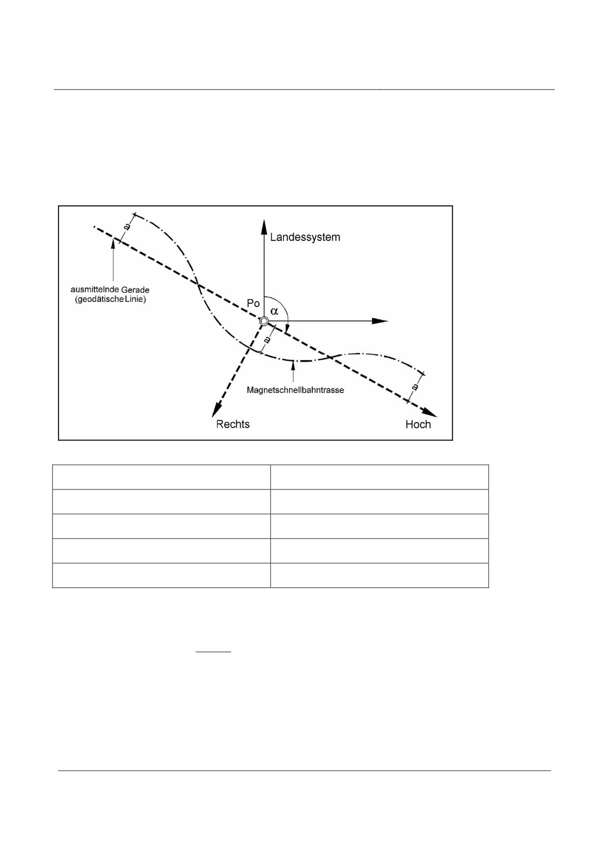
High-speed Maglev system
Maglev Technical Committee
Design principles
Guideway
In this projection a geodetic line, defined by the point PO and the azimuth α, is projected with length
preservation.
To minimise the distance distortions, which increase with lateral distance a, the geodetic line is pla-
ced over the route as an averaging straight line.
Figure 251 shows as an example the fictitious position of a high-speed Maglev route and an advan-
tageously positioned geodetic line, as well as the axis designations.
Figure 251: Parameter representation of the high-speed Maglev co-ordinate system (MCS)
Landessystem
National system
ausmittelnde Gerade (geodätische Linie)
Averaging line (geodetic line)
Magnetschnellbahntrasse
High-speed Maglev route
Rechts
Longitude
Hoch
Latitude
The remaining distance distortions (scale differences) can be estimated by:
2
a
Lv
≈
2
2⋅R
m
(1)
where Rm = average radius of the Earth (6378 km)
The increase of these distance distortions with growing distance from the averaging straight line is
shown in Table 156 based upon calculated examples.
Title
High-speed Maglev system, design principles
Guideway, Part V, Surveying
Doc. No.:
60641
Version White pa-
Issue date
15.02.2007
Page 14
per
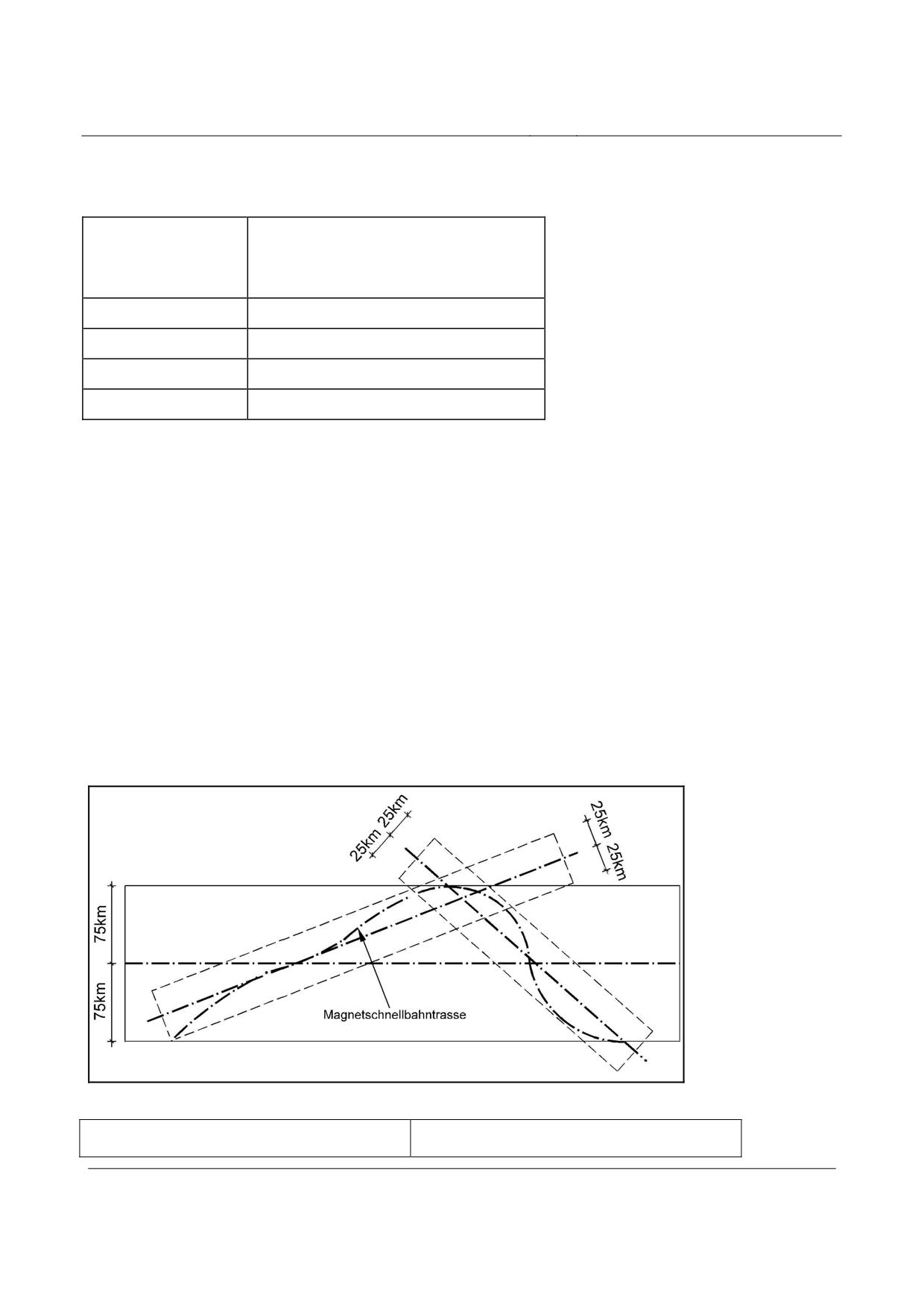
High-speed Maglev system
Maglev Technical Committee
Design principles
Guideway
Lateral distance a
Distance distortion Lv per 100 m
[km]
[mm/100 m]
10
+0.1
25
+0.8
50
+3.1
75
+6.9
Table 156: Projection distortions
The maximum lateral distance of the route to the selected geodetic line through PO should be around
25 km.
This limitation means that the remaining deviations (projection distortions) lie in an order of magni-
tude of 1 mm per 100 m and are thus within tolerable magnitudes. They can thus be disregarded in
all subsequent calculations / measurements.
The required calculations can then take place according to the simple formulae of plane trigonome-
try. In particular, the application of projection reductions can be dispensed with.
If the recommended maximum lateral distance a ≤ 25 km cannot be adhered to, several MCS secti-
ons with sufficiently large areas of overlap (at least 3 points of the higher-level fixed-point frame
each, corresponding to approx. 6 km length) should be defined. Such an arrangement is shown in
Figure 252.
Figure 252: Lateral limitation of the MCS
Magnetschnellbahntrasse
High-speed Maglev route
Title
High-speed Maglev system, design principles
Guideway, Part V, Surveying
Doc. No.:
60641
Version White pa-
Issue date
15.02.2007
Page 15
per
High-speed Maglev system
Maglev Technical Committee
Design principles
Guideway
Regardless of the properties of the above-mentioned projection, route measurements (in additional
to the normal instrument and atmospheric corrections) must be geometrically reduced in the deter-
mination of the fixed-point network and during construction (reduction to the horizontal and const-
ruction horizon and taking into account the curvature of the earth).
The determination of the MCS (position) should take place in the following sub-steps:
(1)
Determination by maps of an averaging straight line such that the lateral distances be-
tween route and averaging straight lines are no more than 25 km (subdividing into sev-
eral sections if necessary).
(2)
Graphical determination of a reference point PO (ϕo, λo) on the averaging straight line in
the central area of the route (with rounded ellipsoidal co-ordinates if appropriate).
(3)
Determination graphically or by calculation of the ellipsoidal azimuth α of the averaging
straight line at this reference point PO.
(4)
Determination of the MCS such that
- the zero point is identical with the above-mentioned reference point PO and
- the positive latitude axis corresponds to the geographical North in PO.
(5)
Projection of this North-oriented system in the map or calculation level in accordance with
the rules for an inclined-axis conformal projection. Here the averaging straight line run-
ning through the reference point PO (ϕo, λo) at the geographic direction angle α (corre-
sponds to the ellipsoid of a geodetic line) is projected in the plane system with length
preservation.
(6)
Rotation in the (longitude / latitude) co-ordinate system (oriented in the main direction of
the route) with subsequent additive zero-point displacement by the values latitudeO and
longitudeO (to avoid negative co-ordinates).
- latitude = longitudeLK · sin(α) + latitudeLK · cos(α) + latitudeo
- longitude = longitudeLK · cos(α) - latitudeLK · sin(α) + longitudeo
(2)
Projection and transformation
The projection by calculation of the ellipsoidal co-ordinates for the points of the higher-level fixed
point framework (cf. Chapter Error! Reference source not found.), generally derived from GPS
measurements, takes place on the basis of the above-mentioned definitions (ϕo, λo and α).
For expedience, this projection is based upon the same ellipsoidal parameters (large semiaxis and
oblateness) of the reference ellipsoid (currently WGS84), upon which the ellipsoidal co-ordinates
are based.
We will dispense here with the representation of the comprehensive and confusing functions of the
inclined-axis conformal projection. The mathematical principles can be found in geodetic technical
literature.
The above-mentioned transformation equations are series, the development of which is limited to a
corresponding calculation accuracy. In addition to the above-mentioned distance distortions to the
Title
High-speed Maglev system, design principles
Guideway, Part V, Surveying
Doc. No.:
60641
Version White pa-
Issue date
15.02.2007
Page 16
per
High-speed Maglev system
Maglev Technical Committee
Design principles
Guideway
side of the line to be projected with length preservation (and the resulting maximum stripe width of
25 km to each side; see Chapter 0) this also limits the field of application (longitudinal extension).
This limitation is primarily dependent upon the following parameters:
(1)
Geographic width ϕo of the reference point PO,
(2)
Orientation α of the primary axis (latitude),
(3)
Longitudinal extension of the MCS,
(4)
Stripe width of the MCS and
(5)
Break off criterion in the calculation program used.
In order to keep calculation errors low enough to be negligible, the following are defined as reliable
calculation accuracies:
(1)
Maximum 1 mm between adjacent points at a distance of 1 km,
(2)
Maximum 20 mm for the most distant point in relation to the co-ordinate origin.
In order to keep subsequent height reductions low the MCS is defined at an average construction
horizon. From a calculation point of view the consideration of the construction horizon takes place
for expedience by the adaptation of the parameters of the reference ellipsoid in the above-
mentioned calculations. Depending upon the topography of the route it is sometimes possible to
avoid height reductions in this manner, which is particularly advantageous during the detailed rout-
ing and the pegging out during construction.
Height component
As a height system, a fixed-point field is created that guarantees the adjacency preservation nec-
essary for the routing of the high-speed Maglev system.
The height network is connected to the ordnance survey height reference area via connecting mea-
surements. This simplifies co-ordination with other technical planning and the acceptance of data
regarding the existing infrastructure.
The adjustment of the height network should be performed by a constraint-free positioning.
If there are different national height networks within the route, subsections can be created. If indi-
vidual points or groups of points are connected to several height systems (e.g. system of Deutsche
Bahn AG, the German waterways and shipping administration, etc.), independent point numbers
should be issued for unique identification.
Realisation
The MCS is realised by the totality of all fixed points for position and height. The network structure
is performed in two stages (for both position and height), these are broken down into:
Title
High-speed Maglev system, design principles
Guideway, Part V, Surveying
Doc. No.:
60641
Version White pa-
Issue date
15.02.2007
Page 17
per
High-speed Maglev system
Maglev Technical Committee
Design principles
Guideway
(1)
Creation of a higher-level fixed point network with point spacing of approx. 3000 m (cf.
Chapter 0) for the performance of the work required for detailed routing and for subse-
quent integration in sections of the fixed point field for the route. The plane co-ordinates
(longitude / latitude) or the height are determined according to the data in Chapter 0 and
Error! Reference source not found..
(2)
The creation of a fixed point network for the route with point spacings of approx. 200 m
(cf. Section 0) for surveying to assist construction.
The co-ordination of these points (position and height) takes place under forced connec-
tion to the higher-level fixed point framework.
The following reasons, amongst others, exist for the two-stage network structure:
(1)
The necessary network homogeneity over the entire planning and construction phase;
(2)
The technically well-balanced connection to the national system that can be made at a
reasonable economic cost (see Chapter 0);
(3)
Different measurement procedures used.
Title
High-speed Maglev system, design principles
Guideway, Part V, Surveying
Doc. No.:
60641
Version White pa-
Issue date
15.02.2007
Page 18
per
High-speed Maglev system
Maglev Technical Committee
Design principles
Guideway
Higher-level fixed point network of the MCS
According to the fundamental geodetic principle “from big to small”, a wide-meshed network with
point spacings of approx. 3000 m should be set up along the route. This point field firstly serves the
detailed planning or detailed routing.
Furthermore, it forms the framework into which the route-related fixed point network for the const-
ruction-related surveying work (see Section 0) is linked.
The points of the higher-level fixed-point network should be found such that
(1)
Permanent point stability is guaranteed,
(2)
GPS measurements can be performed (low shadowing),
(3)
Route obstacles can be detected for the detailed routing,
(4)
The subsequent connection of the route-related fixed point network (with higher point
density) is facilitated (accessibility, visual connections, stability) and
(5)
If possible, there are visual connections to the adjacent points of the higher-level fixed-
point framework.
The investigation should be documented in the network design including an explanatory report ta-
king into account the measuring procedure used.
The network design should be checked with regard to quality and economic viability by means of a
simulated adjustment calculation and optimised if necessary.
The plane co-ordinates (longitude / latitude) and the height are determined according to the specifi-
cations in Chapter 0 and Error! Reference source not found..
Position determination
The determination of the position of the points of the higher-level fixed point framework should
take place using satellite-assisted measurement procedures.
For independent checking of scale, selected side lengths of the fixed-point network should be de-
termined by means of conventional procedures (electro-optical distance measurement).
The free positioning in the national system takes place using identical points (e.g. EUREF, DREF
points or higher-order TPs). A scale reduction should be applied if necessary.
The resulting positional co-ordinates are converted into the plane, right-angled MCS in accordance
with Chapter 0.
All parameters should be three-dimensionally balanced out together with the GPS measurements.
Title
High-speed Maglev system, design principles
Guideway, Part V, Surveying
Doc. No.:
60641
Version White pa-
Issue date
15.02.2007
Page 19
per
High-speed Maglev system
Maglev Technical Committee
Design principles
Guideway
The positional accuracies listed should be adhered to:
• Point-related accuracy in accordance with HELMERT
< 5 mm
• Relative accuracy of the base lines
< (5 mm + 1 ppm)
Height determination
The height determination of the fixed points of the higher-level fixed-point framework takes place
by means of geometric detailed levelling.
The stated discrepancy (D) of the forward and backward levelling between two adjacent fixed
points should be adhered to:
D[m]=±3⋅
S[m]
(3)
See Chapter Error! Reference source not found. for the definition of the height system of the
MCS and for the adjustment sequence according to the procedure.
Title
High-speed Maglev system, design principles
Guideway, Part V, Surveying
Doc. No.:
60641
Version White pa-
Issue date
15.02.2007
Page 20
per
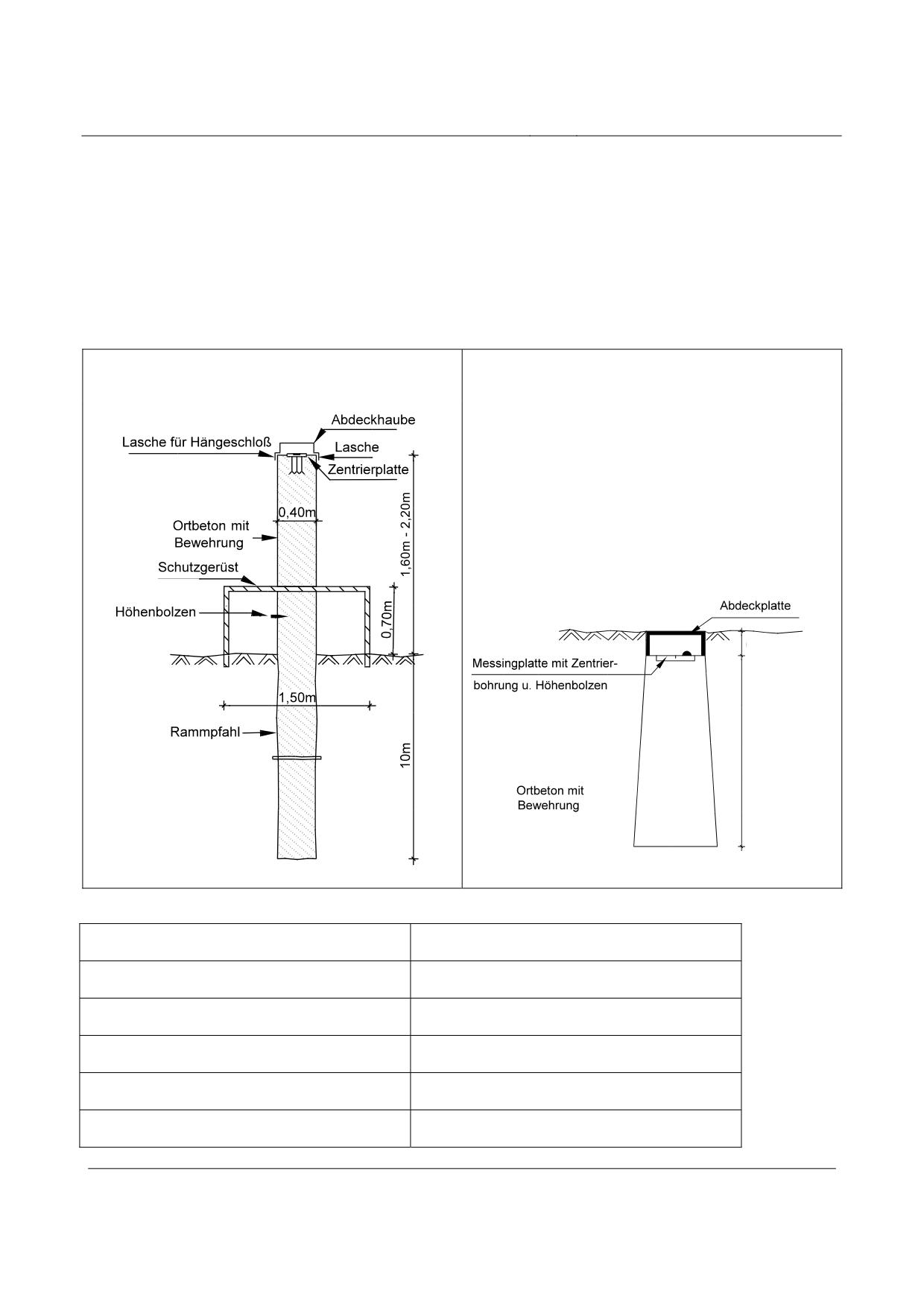
High-speed Maglev system
Maglev Technical Committee
Design principles
Guideway
Marking out
The individual fixed points (position and height) should be marked out in a stable and permanent
manner.
The marking out (see Figure 253 for example) should be performed in good time due to possible
initial settling.
Local concrete pillars with positive centering and
Base point with centering hole and height pegs
concreted-in height pegs
0,10 m - 0,20 m
0,80 m - 1,00 m
Figure 253: Examples of the design of fixed-point markers
Lasche für Hängeschloß
Shackle for padlock
Abdeckhaube
Covering cap
Lasche
Shackle
Zentrierplatte
Centering plate
Ortbeton mit Bewehrung
Site-mixed reinforced concrete
Schutzgerüst
Guard scaffolding
Title
High-speed Maglev system, design principles
Guideway, Part V, Surveying
Doc. No.:
60641
Version White pa-
Issue date
15.02.2007
Page 21
per
High-speed Maglev system
Maglev Technical Committee
Design principles
Guideway
Höhenbolzen
Height peg
Rammpfahl
Driven foundation pile
Abdeckplatte
Covering plate
Messingplatte mit Zentrierbohrung u. Höhenbol-
Brass plate with centering hole and height peg
zen
Title
High-speed Maglev system, design principles
Guideway, Part V, Surveying
Doc. No.:
60641
Version White pa-
Issue date
15.02.2007
Page 22
per
High-speed Maglev system
Maglev Technical Committee
Design principles
Guideway
Transformation of the planning system in MCS
The planning documents from the national system should each be transferred into the MCS in secti-
ons by means of a 4-parameter transformation.
In addition, from each two adjacent fixed points of the higher-level fixed-point network the parame-
ters
(1)
2 x translation
(2)
1 x rotation
(3)
1 x scale factor
should be determined for the 4-parameter positional transformations.
Graphical planning contents should be transformed in sections using the determined transformation
parameters.
Title
High-speed Maglev system, design principles
Guideway, Part V, Surveying
Doc. No.:
60641
Version White pa-
Issue date
15.02.2007
Page 23
per
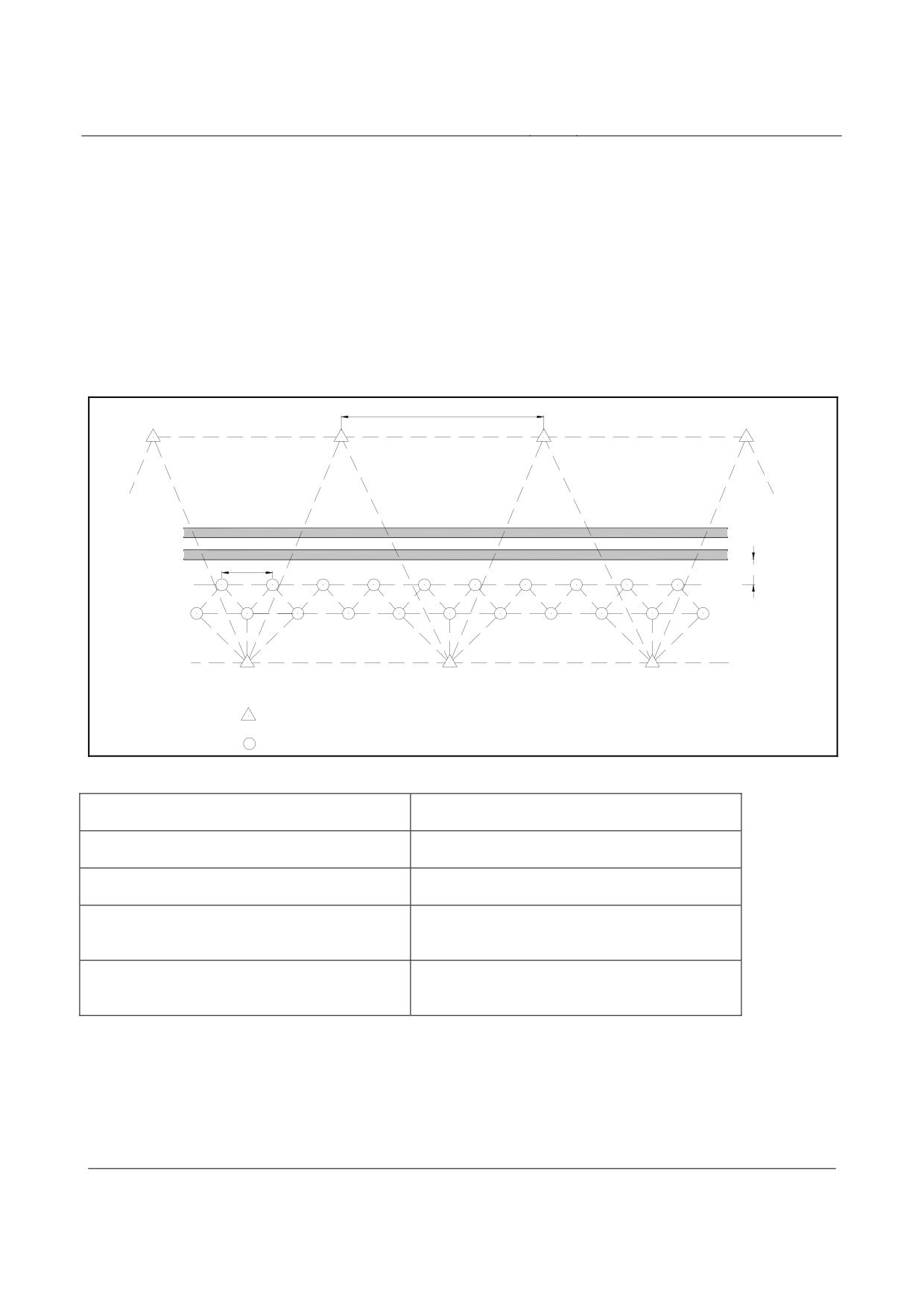
High-speed Maglev system
Maglev Technical Committee
Design principles
Guideway
Route-related fixed-point network in the MCS
As the basis for all construction-related surveying work (marking out, detailed positioning, accep-
tance, etc.) the higher-level fixed-point network described in Chapter 0 should be compressed.
The point spacing of the route-related fixed-point network is approx. 200 m.
The lateral distance of the fixed points to the planned guideway is generally 30 m to 60 m (see Fi-
gure 254).
In special cases (e.g. vicinity of stations, grade separation structures) a smaller compression interval
or a smaller lateral distance from the high-speed Maglev layout is possible.
2 - 3 km
geplante MSB-Trasse
ca. 200m
Abstand ca. 30 - 60m
Übergeordneter Festpunktrahmen (z.B mittles GPS-Messungen)
Trassenbegleitendes Festpunktfeld (Verdichtung z.B mittels Tachymetermessungen)
Figure 254: Recommended route-related fixed-point field
geplante MSB-Trasse
Planned high-speed Maglev route
Distance
Spacing
ca.
approx.
Übergeordneter Festpunktrahmen (e.g. mittles
Higher-level fixed-point framework (e.g. central
GPS-Messungen)
GPS measurements)
Trassenbegleitendes Festpunktfeld (Verdichtung
Route-related fixed-point field (compression e.g.
z.B. mittels Tachymetermessungen)
by means of tachymeter measurements)
The co-ordination of these points (position and height) takes place under forced connection to the
higher-level fixed-point network.
Title
High-speed Maglev system, design principles
Guideway, Part V, Surveying
Doc. No.:
60641
Version White pa-
Issue date
15.02.2007
Page 24
per
High-speed Maglev system
Maglev Technical Committee
Design principles
Guideway
Position determination
The position determination of the route-related fixed-point field should be performed at a high level
of accuracy in accordance with the latest measuring technology developments.
The listed positional accuracies should be adhered to:
• Point-related accuracy according to HELMERT
< 2 mm
The measuring accuracies for the route-related positional fixed-point network are defined as fol-
lows:
Standard deviation of the arithmetic mean
• of a measured direction
sa(Hz) = 0.2 mgon
• of a measured distance to adjacent point
sa(Sh) = 1.0 mm
The calculation of co-ordinates (position) of all newly defined fixed points between two points of
the higher-level fixed-point framework takes place by common network adjustment in the plane
(longitude / latitude) system of the MCS.
The individual measuring elements should be assigned a weighting based on their standard deviati-
ons.
The adjustment accuracy below should be adhered to:
sa((∆long, ∆lat) = 1.0 mm
adjusted co-ordinate difference
Standard deviations of the adjusted co-ordinate difference ∆longitude or ∆latitude of two ad-
jacent route-related fixed-points
Title
High-speed Maglev system, design principles
Guideway, Part V, Surveying
Doc. No.:
60641
Version White pa-
Issue date
15.02.2007
Page 25
per
High-speed Maglev system
Maglev Technical Committee
Design principles
Guideway
Height determination
The height determination of the route-related fixed-point network takes place by means of geo-
metric detailed levelling.
The stated discrepancy (D) between the forwards and backwards levelling between two adjacent
route-related fixed points should be adhered to:
D[mm]=±3⋅
S[m]
(4)
The measured values should arranged in sections to form height networks and adjusted under forced
connection to the higher-level height fixed-point framework. If height points of the national height
fixed-point field are drawn into the MCS then these are treated as new points, i.e. the existing natio-
nal heights remain unconsidered.
The adjustment accuracy stated below should be adhered to:
sa((∆height) = 1.0 mm
adjusted height difference
Standard deviation of an adjusted height deviation between two adjacent route-related fixed
points
Title
High-speed Maglev system, design principles
Guideway, Part V, Surveying
Doc. No.:
60641
Version White pa-
Issue date
15.02.2007
Page 26
per
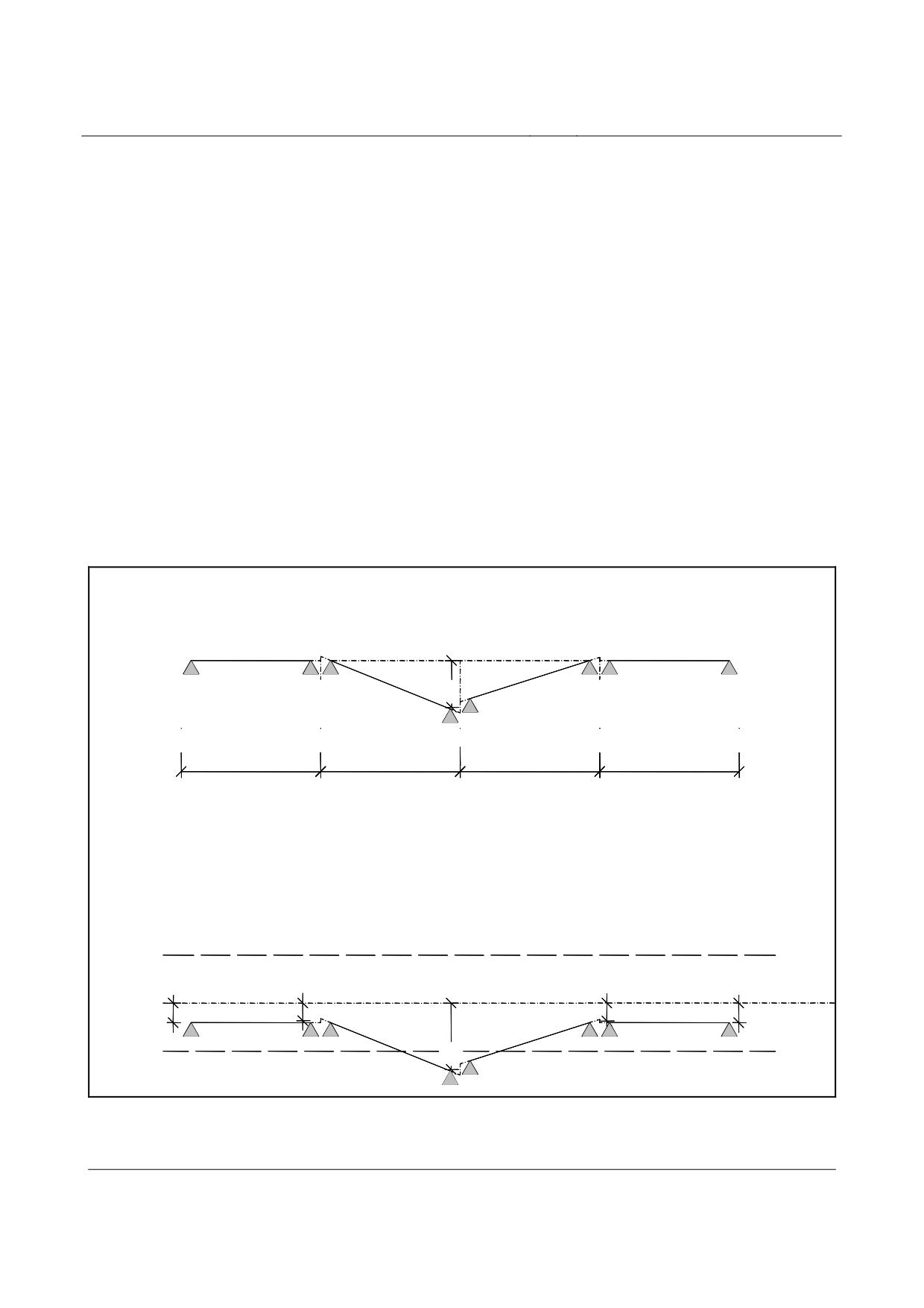
High-speed Maglev system
Maglev Technical Committee
Design principles
Guideway
Detailed positioning of the guideway beams
The detailed positioning of the guideway beams takes place some time after the rough assembly
(the laying) of the guideway beams.
The procedure for the detailed positioning should be drawn up on a project-specific basis.
The geometric requirements of the functional levels within the guideway beams are described in
/MSB AG-FW GEO/.
The longwave deviations should be calculated for the two functional levels stator level (in z-
direction) and lateral guidance level (in y-direction), taking into account the calculated target pre-
bending.
The requirements for the relative spatial position are derived from the permissible longwave devia-
tion within the guideway beam.
Adherence to the permissible tolerances for these longwave deviations in the y- and z-direction of
the BPC (beam production co-ordinate system), (/MSB AG-FW GEO/) prevents unplanned accel-
erations and jerks.
1. Relative Lage der Fahrwegträger zueinander
relative Solllage
dy
1
LSys
LSys
LSys
LSys
2. Absolute Lage der Fahrwegträger zur Raumkurve
-5
globale Solllage (Raumkurve)
dy
dy
dy2
dy
2
2
2
2
dy
+5
2
Figure 255: Requirements of the detailed positioning of the guideway beams
Title
High-speed Maglev system, design principles
Guideway, Part V, Surveying
Doc. No.:
60641
Version White pa-
Issue date
15.02.2007
Page 27
per
High-speed Maglev system
Maglev Technical Committee
Design principles
Guideway
Relative Lage der Fahrwegträger zueinander
Position of guideway beams in relation to one
another
relative Solllage
Relative target position
Absolute Lage der Fahrwegträger zur Raumkurve
Absolute position of guideway beams on three-
dimensional curve
globale Sollage (Raumkurve)
Global target position (three-dimensional curve)
For the detailed positioning of a guideway beam the requirements are divided into the
• relative spatial position (in each case considering the previous and next guideway beam) and
• absolute spatial position (position of the guideway in relation to the three-dimensional cur-
ve).
The measuring points on the functional levels stator level, lateral guidance rails and sliding surfaces
are defined in /MSB AG-FW GEO/ within the beam.
The requirements relate to the average beam position in the beam joint (system axis). The permis-
sible tolerance of the relative spatial position of the guideway beam (spanning beams) in the beam
joint is:
For beam lengths > 12.384 m:
dy
=±
⋅L
1
sys
24768
[mm]
(5)
dz
=±
⋅L
1
sys
24768
[mm]
(6)
where Lsys = field width (e.g. 24768 mm)
For beam lengths < 12.384 m:
dy
=
±
1
[mm]
dz
1
=
±
[mm]
The geometric requirements of the offset and the NGK in the beam joint are defined in /MSB AG-
FW GEO/.
The permissible tolerance of the absolute spatial position of the guideway beam in relation to the
planned three-dimensional curve is as follows in the beam joint:
Title
High-speed Maglev system, design principles
Guideway, Part V, Surveying
Doc. No.:
60641
Version White pa-
Issue date
15.02.2007
Page 28
per
High-speed Maglev system
Maglev Technical Committee
Design principles
Guideway
dy
=
±
2
[mm]
dz
=
±
2
[mm]
Title
High-speed Maglev system, design principles
Guideway, Part V, Surveying
Doc. No.:
60641
Version White pa-
Issue date
15.02.2007
Page 29
per
High-speed Maglev system
Maglev Technical Committee
Design principles
Guideway
Documentation
The requirements of the quality assurance and documentation are set down in /MSB-AG FW
ÜBG/.
Title
High-speed Maglev system, design principles
Guideway, Part V, Surveying
Doc. No.:
60641
Version White pa-
Issue date
15.02.2007
Page 30
per
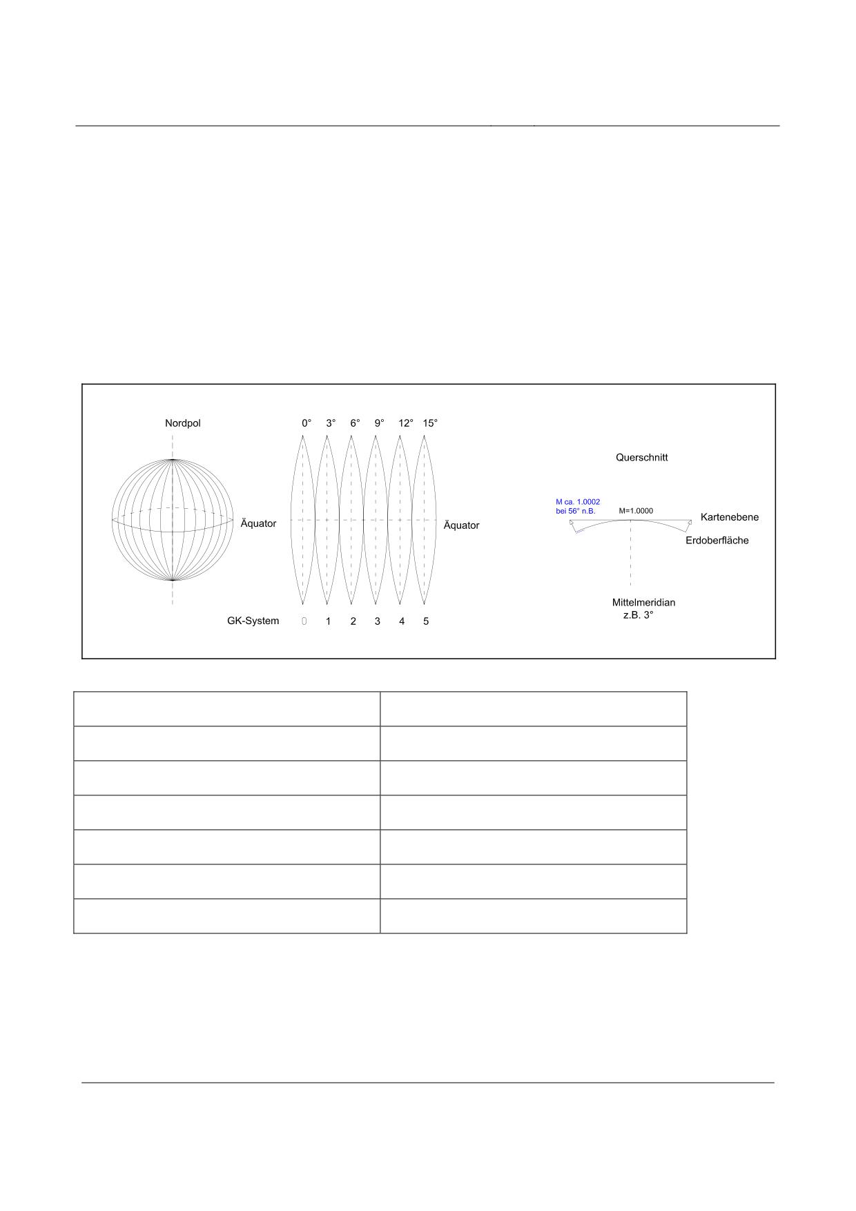
High-speed Maglev system
Maglev Technical Committee
Design principles
Guideway
Appendix V-A Gauß-Krüger co-ordinate system
Official topographical maps, in particular those with large and medium scale, build upon the
Gauß-Krüger co-ordinate system.
Gauß-Krüger co-ordinates are a conformal projection of the ellipsoid of the earth as a plane.
The earth is divided into meridian stripes 3° wide. Its limiting meridians lie precisely 3° apart. In
the centre of the meridian stripe runs the so-called central meridian. Each meridian stripe has a
reference figure. In the classic determination this is derived from the integer multiplication of 3° for
the central meridian (0°, 3°, 6°, etc.).
Figure 256: Scale distortion in the Gauß-Krüger system
Nordpol
North pole
Querschnitt
Cross-section
Kartenebene
Map plane
Erdoberfläche
Surface of the earth
Äquator
Equator
GK-System
GK system
Mittelmeridian
Central meridian
For mapping the curved surface of the earth is projected onto the map plane. The projection distor-
tions that arise increase with increasing distance from the central meridian (see Figure 256).
These locally-differing length distortions must be taken into account by calculation in the detailed
planning (detailed routing) and the local conversion of all relevant subsystems of the high-speed
Maglev system. A continuous routing calculation with “true” distances is not possible.
Title
High-speed Maglev system, design principles
Guideway, Part V, Surveying
Doc. No.:
60641
Version White pa-
Issue date
15.02.2007
Page 31
per
High-speed Maglev system
Maglev Technical Committee
Design principles
Guideway
All relevant components (e.g. guideway beams, longitudinal stators) and e.g. the directory of e-
quipment would have to be taken into account in the planning co-ordinate system with correspon-
ding scale factors.
Title
High-speed Maglev system, design principles
Guideway, Part V, Surveying
Doc. No.:
60641
Version White pa-
Issue date
15.02.2007
Page 32
per
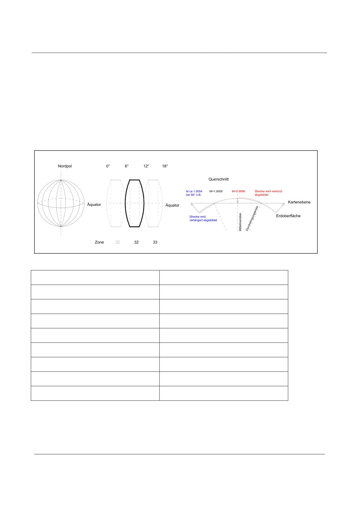
High-speed Maglev system
Maglev Technical Committee
Design principles
Guideway
Annex V-B Universal, transversal mecator projection
For the ordnance surveying of all German Länder the ETRS89 (European Terrestrial Reference
System 1989) with UTM projection will be compulsory as of 2009.
The ETRS89 is a three-dimensional Cartesian co-ordinate system. It relates to geocentric co-
ordinates the origin of which lies in the geocentre (centre of gravity of the earth). In UTM projecti-
on, the ellipsoid of the earth is divided into 6° wide stripes, which all run through the poles and are
at the greatest distances from each other at the equator.
Figure 256: Scale distortion in the UTM system
Nordpol
North pole
Querschnitt
Cross-section
Äquator
Equator
Strecke wird verkürzt abgebildet
Section is shortened in projection
Kartenebene
Map plane
Erdoberfläche
Surface of the earth
Mittelmeridian
Central meridian
Durchdringungskreis
Penetration circle
Strecke wird verlängert abgebildet
Section is extended in projection
For UTM projection the curved surface of the earth is projected onto the map plan using 2 penetra-
tion circles. Only on the penetration circles is the depiction length-preserving. Between the penetra-
tion circles, distances are compressed, outside the penetration circles, distances are extended (see
Figure 256).
Title
High-speed Maglev system, design principles
Guideway, Part V, Surveying
Doc. No.:
60641
Version White pa-
Issue date
15.02.2007
Page 33
per
High-speed Maglev system
Maglev Technical Committee
Design principles
Guideway
These locally differing length distortions must be taken into account in the detailed planning (detai-
led routing) and the local conversion of all relevant subsystems of the high-speed Maglev system by
calculation. A continuous routing calculation with “true” lengths is not possible.
All relevant components (e.g. guideway beams, long stators) and e.g. the list of equipment would
have to be taken into account in the planning co-ordinate system with suitable scale factors.
Title
High-speed Maglev system, design principles
Guideway, Part V, Surveying
Doc. No.:
60641
Version White pa-
Issue date
15.02.2007
Page 34
per
High-speed Maglev system
Maglev Technical Committee
design principles
Guideway
High-speed Maglev system
Design principles
Guideway
Part VI
Maintenance
The copyright to this document and all appendices remains the property of the creator.
All rights reserved
Title
High-speed Maglev system design principles
Guideway Part VI - Maintenance
Doc.no.:
63842
Version
White paper
Issue date
15.02.2007
Page 1
High-speed Maglev system
Maglev Technical Committee
design principles
Guideway
Distributor
This document was released for publication by the ‘Guideway’ committee of experts.
Title
High-speed Maglev system design principles
Guideway Part VI - Maintenance
Doc.no.:
63842
Version
White paper
Issue date
15.02.2007
Page 2
High-speed Maglev system
Maglev Technical Committee
design principles
Guideway
Overview of revisions
Date of release: 15.02.2007, currently valid version, ‘Guideway’ committee of experts.
Title
High-speed Maglev system design principles
Guideway Part VI - Maintenance
Doc.no.:
63842
Version
White paper
Issue date
15.02.2007
Page 3
High-speed Maglev system
Maglev Technical Committee
design principles
Guideway
Table of contents
Distributor
2
Overview of revisions
3
Table of contents
4
General
6
Purpose and field of application
6
Design principles for high-speed Maglev systems
6
Abbreviations and definitions
7
Laws, decrees, standards and directives
7
Identification and binding nature of requirements
7
Requirements regarding guideway maintenance
8
Basic principles
8
Specifications and recommendations for the maintenance strategy
9
Specifications
9
Recommmendations
Error! Bookmark not defined.
Requirements of personnel
10
Servicing
11
Inspections
12
General requirements relating to inspections
12
Monitoring
12
Investigations
13
Appraisals
14
Special inspections
14
Maintenance
16
Other measures
17
Requirements regarding the sequences of maintenance processes
18
Technical notes on the performance of inspections
20
Possibility of monitoring
20
Degree of automation of the inspections
20
Inspection of the geometry
20
Visual inspections
21
Inspection by means of stationary measuring devices
21
Other inspections
21
Title
High-speed Maglev system design principles
Guideway Part VI - Maintenance
Doc.no.:
63842
Version
White paper
Issue date
15.02.2007
Page 4
High-speed Maglev system
Maglev Technical Committee
design principles
Guideway
Fundamental requirements regarding documentation
22
Title
High-speed Maglev system design principles
Guideway Part VI - Maintenance
Doc.no.:
63842
Version
White paper
Issue date
15.02.2007
Page 5
High-speed Maglev system
Maglev Technical Committee
design principles
Guideway
General
Purpose and field of application
This document specifies in binding terms the general specifications for the maintenance of high-
speed Maglev guideways, insofar as safety and order are involved. Furthermore, these design prin-
ciples contain recommendations.
This document is one of the foundations that should be taken into account in the design, planning,
realisation and operation of application projects of the high-speed Maglev.
The statements in the document are subordinate to those of the MbBO and are based upon the e-
xisting state of the art for the maintenance of structures.
Part VI of the guideway design principles should be used in association with Parts I to V of the gui-
deway design principles, the complete system design principles and the design principles relating to
the other subsystems.
This document includes:
•
General requirements for guideway maintenance;
•
Fundamental requirements for the processes of guideway maintenance;
•
Fundamental requirements for the technical performance of monitoring;
•
Fundamental requirements for documentation;
The requirements of this document should be more precisely specified and supplemented on a pro-
ject-specific basis and according to the current status of the project.
Requirements regarding the maintainability of the individual assemblies can be found in the /MSB
AG-FW ÜBG/.
These design principles apply for a high-speed Maglev system in accordance with the Allgemeinem
Magnetschwebebahngesetzt /AMbG/ (General Law on Magnetic Levitation Systems).
Design principles for high-speed Maglev sys-
tems
This document is part of the documentation for high-speed Maglev systems comprising several sets
of design principles. The document tree is shown in Figure 1 /MSB AG-GESAMTSYS/.
The higher-level document ‘Design principles, complete system’ and its appendices apply consis-
tently for the entire documentation:
• High-speed Maglev system design principles, complete system, doc. no.: 50630,
/MSB AG-GESAMTSYS/ with the appendices:
• Annex 1: Abbreviations and definitions, doc. no.: 67536, /MSB AG-ABK&DEF/
• Annex 2: Laws, regulations, standards and directives, doc. no.: 67539,
/MSB AG-NORM&RILI/
• Annex 3: Environmental conditions, doc. no.: 67285, /MSB AG-UMWELT/
Title
High-speed Maglev system design principles
Guideway Part VI - Maintenance
Doc.no.:
63842
Version
White paper
Issue date
15.02.2007
Page 6
High-speed Maglev system
Maglev Technical Committee
design principles
Guideway
• Annex 4: Rules for operation (train service and maintenance), doc. no.: 69061,
/MSB AG-BTR&IH/
• Annex 5: Noise, doc. no.: 72963, /MSB AG-SCHALL/
Abbreviations and definitions
The abbreviations and definitions given in /MSB AG-ABK&DEF/ apply.
The assemblies of the guideway are defined in ‘Design Principles, Guideway, Part I’. In deviation
from the terminology in the other design principles, the terms shortcoming, error and damage are
used in accordance with the terminology of construction in guideway design principles.
A shortcoming in the sense of the document is an impermissible deviation of an assembly from the
target state that existed at the moment of acceptance. It is insignificant here whether the shortco-
ming was recognised at the moment of acceptance or not until later. A shortcoming can cause one
or more cases of damage.
An error is an inappropriate action or an omission which can lead to one or more shortcomings and /
or cases of damage.
Damage is an impermissible deviation of an assembly from the target state which occurs during
use.
Laws, regulations, standards and directives
The normative documents listed in /MSB AG-NORM&RILI/ contain statements that become part of
the high-speed Maglev design principles when referred to in the high-speed Maglev design princi-
ples. In the case of dated normative documents in /MSB AG-NORM&RILI/ subsequent changes or
revisions to these publications do not apply. In the case of undated references the latest edition of
the normative document referred to applies.
The status of the standards and directives to be taken into consideration in a Maglev project must
be specified on a project-specific and binding basis.
Identification and binding nature of require-
ments
In the creation of this document the rules in accordance with /DIN 820/ were mainly applied.
In the sections that follow and in the appendices to this document
• requirements are printed in standard type and
• explanations, guide values and examples are printed in italics
(see /MSB AG-FW ÜBG/).
Title
High-speed Maglev system design principles
Guideway Part VI - Maintenance
Doc.no.:
63842
Version
White paper
Issue date
15.02.2007
Page 7
High-speed Maglev system
Maglev Technical Committee
design principles
Guideway
Requirements regarding guideway maintenance
Basic principles
In accordance with DIN 31051 the maintenance of the guideway comprises
(1)
Inspection,
(2)
Servicing,
(3)
Maintenance and improvements
of the named components of the guideway (the improvements are dealt with in this document to-
gether with other, e.g. operationally determined measures).
The overriding goal of maintenance is to put in place the technical prerequisites for the continuation
of the operation of the high-speed Maglev system in accordance with regulations. Preventative and
condition-oriented maintenance should ensure that repairs leading to disruption to the guideway are
not necessary.
The monitoring and testing of the guideway should accompany operation and should be automated
as far as possible. The safety level achieved may not be lower than in a conventional structure test
on the basis of /DIN 1076/ or the valid regulations regarding wheel/rail technology. The time inter-
vals specified in these regulations can however be adapted to the peculiarities of a high-speed
Maglev route where appropriate.
The purpose of the regular monitoring is to recognise shortcomings and any damage that have oc-
curred early enough that the necessary measures can be taken at an early stage or to rectify short-
comings and any defects that have arisen before safety and availability are impaired.
Furthermore, the necessary data material for a forward-looking maintenance planning should be
provided.
The independence of the personnel entrusted with the maintenance for the guideway regarding
technical decisions in relation to
(1)
the necessity of the performance of inspection measures;
(2)
the technical release;
shall be ensured by appropriate organisational rules.
A project-specific maintenance concept shall be drawn up for the engineering structures of the gui-
deway in accordance with /MSB AG-FW ÜBG/, containing statements regarding the monitoring
and testing of the structures of the guideway for the high-speed Maglev system in relation to stabili-
ty, traffic safety and durability.
Note: According to MbBO there is a duty of disclosure towards the supervising and testing agency
with regard to data and findings that are relevant to the monitoring and testing of the structure and
that are detected and assessed within the framework of operation.
It should be ensured that in addition to the person responsible for the system, the works manager
and the responsible supervisory body, third parties who can demonstrate a legitimate interest in the
results of investigation (e.g. project manager for crossing traffic routes), are informed of maintenan-
ce events that are relevant to them.
Title
High-speed Maglev system design principles
Guideway Part VI - Maintenance
Doc.no.:
63842
Version
White paper
Issue date
15.02.2007
Page 8
High-speed Maglev system
Maglev Technical Committee
design principles
Guideway
Specifications and recommendations for the
maintenance strategy
Specifications
The maintenance of the guideway rests upon a known condition. This condition is recorded and
documented in the framework of the manufacture and maintenance of the guideway as the “zero
condition” on the finished guideway (section) before its first negotiation by a Maglev vehicle.
During subsequent operation all significant changes from the original “zero condition” are continu-
ously documented and assessed and if necessary set down as a new reference condition.
Any substitution of components in the existing equipment (e.g. exchange of a stator assembly) can
necessitate the definition of a new reference condition, which then forms the basis for future moni-
toring.
Maintenance programs should be drawn up in accordance with “Principles and procedures for the
drawing up of the maintenance program”, Section 5.3.3 in /MSB AG-GESAMTSYS/ and the /MSB
AG-BTR&IH/.
Maintenance programs should be drawn up for all assemblies by the manufacturer / supplier in
question.
The individual maintenance programs should be summarised in a maintenance program.
The guideway maintenance program developed from this must be compatible with the requirements
of the complete system.
The guideway maintenance program should be drawn up on the basis of the database of structures.
For each individual measure included in the maintenance program the manufacturer / supplier
should drawn up an instruction card for the maintenance in accordance with Section 5.3.3 in /MSB
AG-GESAMTSYS/ and /MSB AG-BTR&IH/.
The construction of the components and assemblies of the guideway should be designed in accor-
dance with the ‘Design Principles, Guideway, Part I’ such that it is fault-tolerant, so that maintenan-
ce need not take place immediately after the detection of damage.
Maintenance-related feedback on other subsystems (e.g. levitation/guidance signals from the vehic-
le) should be taken into consideration in the maintenance of the guideway).
The maintenance must be performed exclusively by suitably qualified personnel (see also /MSB
AG-BTR&IH/).
Possible influence by third parties should be taken into consideration in the maintenance strategy on
a project-specific basis.
Findings and documentation from the manufacture and commissioning should be documented and
drawn upon for the maintenance.
Title
High-speed Maglev system design principles
Guideway Part VI - Maintenance
Doc.no.:
63842
Version
White paper
Issue date
15.02.2007
Page 9
High-speed Maglev system
Maglev Technical Committee
design principles
Guideway
Recommendations
The monitoring of the guideway (where appropriate with the exception of special structures and the
route periphery) should be performed continuously (or at short intervals of time), as far as possible
on an automated basis, and in a manner that supports operations.
Maintenance measures should be performed from the guideway (special vehicle) as far as possible.
The maintenance measures should be planned such that they can be performed within the space
defined for them on a project-specific basis.
The time period available for maintenance measures should be defined on a project-specific basis
(it should take place in the pause in operations to be defined on a project-specific basis).
The evaluation and assessment of the inspection results should take place within a short period of
time. Specially monitored reference objects should be defined at points in the route to be defined on
a project-specific basis.
Drawing upon the other findings from operation and maintenance, the monitoring of the reference
objects should facilitate a condition analysis for the guideway.
Measures relating to structures (e.g. the renewal of the corrosion protection on steel components
after long periods) should be considered separately in the maintenance planning. Assemblies for
which a planned replacement is necessary during the required period of use of the route or for
which the probability of failure leads to the expectation that replacement will be necessary should
be kept in stock in a sufficient number on a project-specific basis.
Requirements relating to personnel
The overriding requirements of the personnel are defined in the design principles for the complete
system.
The leader of the agency responsible for monitoring and testing the guideway must be entitled to
manage the title “engineer”. The position must be occupied by a person with the necessary technical
knowledge and relevant vocational experience of at least five-years.
Title
High-speed Maglev system design principles
Guideway Part VI - Maintenance
Doc.no.:
63842
Version
White paper
Issue date
15.02.2007
Page 10
High-speed Maglev system
Maglev Technical Committee
design principles
Guideway
Servicing
Planning, performance and revision of servicing must take place on the basis of the specifications
defined in Section 5.3.3 in /MSB AG-GESAMTSYS/ and in /MSB AG-BTR&IH/.
Specifications regarding the servicing of the assemblies in the maintenance program and in the
maintenance instructions should take place on a make- and model-specific basis.
The following principles apply for servicing:
(1)
The servicing of the individual assemblies should not obstruct the operation of the system;
(2)
It should be possible to perform the servicing within the times defined on a project-specific
basis;
(3)
It should be possible to perform the servicing within the space to be defined for the mainte-
nance on a project-specific basis;
(4)
It should be possible to perform the servicing using the resources (personnel, equipment) and
processes defined on a project-specific basis;
(5)
The realisability of the servicing tasks should be demonstrated (on a prototype if appropriate)
under preconditions similar to those of application.
Title
High-speed Maglev system design principles
Guideway Part VI - Maintenance
Doc.no.:
63842
Version
White paper
Issue date
15.02.2007
Page 11
High-speed Maglev system
Maglev Technical Committee
design principles
Guideway
Inspections
General requirements relating to inspections
Planning, performance and revision of the inspections must take place on the basis of the specifica-
tions defined in Section 5.3.3 in /MSB AG-GESAMTSYS/ and in /MSB AG-BTR&IH/.
Inspections can be subdivided into:
(1)
Monitoring
(2)
Investigations
(3)
Expert opinions
(4)
Special inspections
Information on the inspection of the assemblies in the maintenance programs and in the maintenan-
ce instructions should take place on a make- and model-specific basis. The following principles
apply for inspections:
(5)
The inspections of the individual assemblies should not obstruct the operation of the system;
(6)
It should be possible to perform the inspections within the times defined on a project-specific
basis;
(7)
It should be possible to perform the inspections within the space to be defined for the mainte-
nance on a project-specific basis;
(8)
It should be possible to perform the inspections using the resources (personnel, equipment)
and processes defined on a project-specific basis;
(9)
The realisability of the inspections should be demonstrated.
This should take place, using a prototype where appropriate, under preconditions similar to those
of application.
The inspection intervals should be defined on a model-dependent and project-specific basis in ac-
cordance with “Principles and Procedures for the Drawing up of the Maintenance Program”.
If the inspection of the assemblies of the guideway does not take place on the basis of /DIN 1076/
or the current state of the art for wheel/rail technology, demonstration of an equal safety level is
necessary.
Monitoring
Monitoring takes place by the annual viewing of the guideway and/or by taking photographs.
Furthermore, at short intervals (continuously where appropriate) supplementary procedures (e.g.
monitoring of functional level geometry) should be applied.
Monitoring is a part of planned inspections to be performed.
It can be vehicle assisted or special vehicle assisted. Project-specific procedures are also possible.
The monitoring of the guideway should take place on a project-specific basis and in a manner de-
pendent upon the make and model.
Regardless of model-specific peculiarities, particular attention should be paid to the following du-
ring monitoring:
Title
High-speed Maglev system design principles
Guideway Part VI - Maintenance
Doc.no.:
63842
Version
White paper
Issue date
15.02.2007
Page 12
High-speed Maglev system
Maglev Technical Committee
design principles
Guideway
(1)
Monitoring of the shortwave geometry of the functional levels;
(2)
Monitoring of the longwave guideway geometry;
(3)
Monitoring the condition of the supports;
(4)
Surface changes (e.g. cracks in the concrete, flaking off of corrosion protection);
(5)
Monitoring of the guideway equipment;
(6)
Monitoring of the defined spaces;
(7)
Monitoring of the special structures and the route periphery;
(8)
Determination of the effects of external influences (collision at road crossings, winter service,
vegetation, earthquakes, vandalism, etc.);
(9)
Where appropriate, monitoring of selected reference objects.
The results should be evaluated continuously and within a short period of time in accordance with
project-specific specifications, so that any shortcomings/damage jeopardising safety and order can
be found without delay.
The necessity of reference objects, and their number and position should be determined on a pro-
ject-specific basis.
Note: These reference objects are, for example, a few guideway beams in exposed positions, to be
specified in co-ordination with the responsible supervisory authorities and their recognised repre-
sentatives. These should be particularly monitored using measuring technology (e.g. temperature
path, carbonisation, coating thickness of the corrosion protection, etc.).
The results of the monitoring of the reference beams are used to evaluate the overall condition of
the route and to evaluate the individual findings.
Investigations
The periods for the investigations should be adjusted in line with the peculiarities of the structural
shape, the loads and the sensitivity of the assemblies. The periods should be stated on a model-
specific basis for all assemblies of the guideway in the project-specific maintenance plan (inspecti-
on plans).
The assemblies of the guideway should be regularly closely inspected for obvious shortcomings or
damage in the framework of the investigation. This close inspection should initially be performed
every year.
This interval can be altered depending upon the project-specific preconditions.
The maximum interval between two investigations is six years.
In the close investigation, particular attention should be paid to shortcomings / damage that are ex-
ternally visible but cannot be detected by the guideway monitoring systems. The investigation also
includes a viewing and evaluation of the monitoring results for the route section that is to be subject
to close investigation.
Title
High-speed Maglev system design principles
Guideway Part VI - Maintenance
Doc.no.:
63842
Version
White paper
Issue date
15.02.2007
Page 13
High-speed Maglev system
Maglev Technical Committee
design principles
Guideway
Appraisals
In an appraisal it should be determined whether:
(1)
The soundness of the assemblies still complies with the specifications from the planning pha-
se and the status of the preceding appraisal;
(2)
There is a danger of the progression of shortcomings and damage within the next six years to
an extent that could significantly impair the fitness for use or soundness;
(3)
Shortcomings, damage or dimensional deviations from the planned condition exist that ne-
cessitate a more detailed investigation.
The appraisal extends to all assemblies of the guideway. Operational influences, which exhibit a not
inconsiderable importance for the guideway (e.g. vegetation in the surrounding area, change to the
peripheral development in the area near the route) should be taken into account. Appraisals should
be performed every six years.
The time between an investigation and an appraisal should be no greater than 3 years.
In the appraisal, all significant shortcomings and damage in the guideway should be assessed and
documented. Any impairment to soundness should be established, evaluated and also documented,
as should the remaining safety and durability. If necessary, special investigations (e.g. additional
geodetic measurements on the guideway) should also be commissioned.
To provide evidence of the appraisal, a detailed report should be drawn up on the scope of the in-
spection, the depth of the inspection and the inspection results. This report should include a predic-
tion on the further course of the shortcomings and damage found. Furthermore, recommendations
should be formulated within it on changes to the maintenance periods and on the maintenance work
necessary within the next appraisal interval.
If procedures for the automated monitoring of the guideway are installed and used and / or reference
objects are monitored, inspection results can be used as part of the appraisal.
If the appraisal of the assemblies of the guideway does not take place on the basis of /DIN 1076/ or
according to the current state of the art in wheel/rail technology, the appraisal should take place by
the evaluation of the results of the previous inspections.
The following points should be taken into account in this connection:
(4)
Continuous monitoring of the guideway or the assemblies covered by this regulation;
(5)
Documentation and evaluation of all inspection results;
(6)
Evaluation of the findings of the monitoring of reference beams;
(7)
Regular close viewing in the framework of the investigations with the focus upon those as-
semblies that are not automatically monitored;
(8)
Accessibility of guideway documentation.
Special inspections
Special inspections must be performed after special events influencing the condition of the guide-
way, or if stipulated by the results of structure inspections.
Events that necessitate a special inspection can be:
(1)
Findings from monitoring, investigation and appraisal;
(2)
Collision of (road) vehicles on the guideway;
Title
High-speed Maglev system design principles
Guideway Part VI - Maintenance
Doc.no.:
63842
Version
White paper
Issue date
15.02.2007
Page 14
High-speed Maglev system
Maglev Technical Committee
design principles
Guideway
(3)
Unforeseen mode of operation of a vehicle with significant effect upon the guideway;
(4)
Conclusion of measures covering structures or maintenance measures on the guideway, if
there is any possibility that the guideway may be damaged due to this work;
(5)
Extraordinary environmental influences.
This list is not comprehensive.
In the framework of a special inspection the stability of the assemblies can also be demonstrated by
experiment (e.g. by loading experiments). In this connection, the performance of tests should be
supported by calculations so that damage to the guideway due to overloading is ruled out. These
experiments may only be planned and performed by specially qualified personnel, and require the
approval of the responsible supervisory bodies.
Title
High-speed Maglev system design principles
Guideway Part VI - Maintenance
Doc.no.:
63842
Version
White paper
Issue date
15.02.2007
Page 15
High-speed Maglev system
Maglev Technical Committee
design principles
Guideway
Maintenance
Planning, performance and revision of maintenance must take place on the basis of the specificati-
ons defined in Section 5.3.3 in /MSB AG-GESAMTSYS/ and in /MSB AG-BTR&IH/.
The following principles apply for maintenance:
(1)
The maintenance of the individual assemblies should not obstruct the operation of the system;
(2)
It should be possible to perform the maintenance within the times defined on a project-
specific basis;
(3)
It should be possible to perform the inspections within the space to be defined for the mainte-
nance on a project-specific basis;
(4)
It should be possible to perform the inspections using the resources (personnel, equipment)
and processes defined on a project-specific basis;
(5)
The realisability of the inspections should be demonstrated (where appropriate on a prototype)
under boundary conditions approximating those of practical application.
The instructions to be drawn up for the maintenance of the guideway must cover at least the follo-
wing points:
(1)
Required personnel (number and qualifications);
(2)
Required equipment and materials;
(3)
Required working time;
(4)
Technological specifications (e.g. hardening times, etc.);
(5)
Predictions regarding environmental influences.
Comprehensive maintenance measures that influence operation should be considered separately and
on a project-specific basis as special measures (examples of this are the full replacement of the cor-
rosion protection on steel components or a fundamental concrete refurbishment).
Title
High-speed Maglev system design principles
Guideway Part VI - Maintenance
Doc.no.:
63842
Version
White paper
Issue date
15.02.2007
Page 16
High-speed Maglev system
Maglev Technical Committee
design principles
Guideway
Other measures
Other measures can be operationally determined or become necessary due to maintenance and
should be defined on a project-specific basis.
They typically include:
(1)
Improvements of/to assemblies;
(2)
Comprehensive maintenance measures that influence operation;
(3)
Measures for the care and control of vegetation;
(4)
Winter service measures.
Similarly, the technical requirements of maintenance as described in this document also apply to the
performance of the other measures. Project-specific concepts and programs should be developed in
good time before the performance of the measures.
Title
High-speed Maglev system design principles
Guideway Part VI - Maintenance
Doc.no.:
63842
Version
White paper
Issue date
15.02.2007
Page 17
High-speed Maglev system
Maglev Technical Committee
design principles
Guideway
Requirements regarding the sequences of maintenance processes
The following requirements are made of the sequences of maintenance processes:
(1)
The specifications in /MSB AG-GESAMTSYS/ and /MSB AG-BTR&IH/ take precedence;
(2)
Maintenance processes that are proven, are not time-critical, can be performed in any
weather and that require little special knowledge on the part of staff should be given prefer-
ence;
(3)
The condition before first use (time of creation) or after maintenance has taken place (actual
condition) must fulfil the specifications according to the plan; this condition should be docu-
mented, it then serves as a reference condition for the evaluation of changes that have occur-
red;
(4)
Determination of the actual condition;
The actual condition, which changes over time and should ideally be known at all times, is
compared with the reference condition and evaluated with regard to the changes that have ta-
ken place; the limits at which measures must be implemented should be defined and set down
for the guideway;
(5)
For all assemblies a preventative, condition-oriented maintenance should be the goal;
(6)
It is possible to deviate from the preventative maintenance for technical, economic or opera-
tional reasons;
(7)
By additional inspections or inspections carried out at closer intervals an extension of the
period of use of assemblies can be achieved;
(8)
Severe damage to the guideway, which cannot be rectified by a simple repair should be taken
into account in the planning of maintenance;
(9)
The required measures (emergency support, replacement of entire beams, etc.) should be con-
ceptually planned in advance to the extent that the maintenance work can be begun within a
short period of time after the occurrence of the damage;
(10)
Measures on third-party systems should be performed in accordance with the general statutory
provisions;
(11)
Express reference is made to the Magnetschwebebahnplanungsgesetz (MBPlG) (Magnetic
Levitation System Planning Act) and the project-specific crossing agreements to be conclu-
ded;
(12)
Measures in the immediate vicinity of the route require project-specific handover and release
procedures.
Note: the following steps should typically be observed in such cases:
(13) Drawing up of a work order e.g. by the organisational unit charged with the maintenance of
the guideway and co-ordination with the train service;
(14) Recorded handover of the work area (e.g. guideway section) from train service to maintenan-
ce;
(15) Performance of the measures and recording of the information required for documentation;
(16) Technical release of the work area by the maintenance;
Title
High-speed Maglev system design principles
Guideway Part VI - Maintenance
Doc.no.:
63842
Version
White paper
Issue date
15.02.2007
Page 18
High-speed Maglev system
Maglev Technical Committee
design principles
Guideway
(17) Recorded acceptance of the work area from the maintenance by the train service;
(18) Documentation of the measures performed.
Note: to make work easier the operational departments can be jointly represented in relation to the
agency charged with the maintenance of the guideway by a “Co-ordinator for train services / struc-
ture testing”. The co-ordinator has a duty of reporting / disclosure in relation to the agency charged
with the maintenance of the guideway and to the supervisory bodies.
Title
High-speed Maglev system design principles
Guideway Part VI - Maintenance
Doc.no.:
63842
Version
White paper
Issue date
15.02.2007
Page 19
High-speed Maglev system
Maglev Technical Committee
design principles
Guideway
Technical notes on the performance of inspections
Possibilities for monitoring
Normally the monitoring procedures to be used can be broken down as follows:
(1)
Measurements from the vehicle (during train service);
(2)
Monitoring by measurement from special vehicle (generally during breaks in train service);
(3)
Stationary monitoring by measuring (generally ongoing);
(4)
Other procedures.
In the selection of the monitoring systems those systems that recognise damage or changes that in-
dicate damage as early as possible should be given preference. The data transfer of the results of
individual monitoring processes generally does not take place online. The evaluation of the data
therefore generally takes place after a time delay; model- and project-specific preconditions should
be taken into account in the setting of evaluation periods.
A decision should be made regarding the necessity of online transfer of monitoring information to
the district control office on a project-specific basis.
Degree of automation of the inspections
The aim should be the maximum possible automation of the monitoring of the guideway. The degree
of automation and the tasks to be performed by the automated inspections should be defined on a
project-specific basis.
If the intention is to draw conclusions about the condition of a large number of assemblies from the
automated inspection of individual assemblies, the number and exposure of the monitoring sensors
should be defined to facilitate a safe prediction.
The functionality of the automated inspection systems should be monitored. The method of recogni-
sing the failure of the automated system should be defined.
The measures that will be taken to ensure that the inspection tasks are still performed even after the
failure of an individual automated system should be defined on a project-specific basis.
For the assemblies with particular relevance to safety, it may be necessary to provide the possibility
of independent checking in an automated inspection for the verification of the measurement or test
results.
Inspection of the geometry
The inspection of the guideway geometry covers the inspection of the shortwave and the longwave
geometry.
In both cases the monitoring should take place on the basis of the documented reference condition.
The inspection of the shortwave geometry (offset, NGK, track gauge, guideway depth, gap) shall
take place according to the state of the art.
Adherence to the specifications defined in /MSB AG-FW GEO/ should be monitored.
Model-specific preconditions (failure recognition, redundancy, error loops) should be taken into
account when specifying the inspection technique.
Title
High-speed Maglev system design principles
Guideway Part VI - Maintenance
Doc.no.:
63842
Version
White paper
Issue date
15.02.2007
Page 20
High-speed Maglev system
Maglev Technical Committee
design principles
Guideway
The inspection of the longwave geometry takes place on the basis of a reference measurement and
according to the state of the art. Geodetic measurements should be performed and documented du-
ring commissioning (see Section 0).
Subsequent geodetic measurements can be used to quantify any changes found or to evaluate the
changes.
Visual inspections
Visual inspections can be both close and automated. The specifications for these should be made on
a project-specific basis and according to the state of the art.
Inspection by means of stationary measuring
devices
Stationary measuring devices are installed at reference objects.
They should correspond with the current state of the art and should be selected by model and in
agreement with the responsible supervisory authorities and where appropriate their recognised
representatives.
The method of recognising the failure of stationary measuring devices should be determined. If
weather data is recorded along the route, the measuring points should be in the immediate proximi-
ty of individual reference objects in order to be able to produce direct relationships between
weather data and measuring data.
Other inspections
Further inspections that are required from the point of view of maintenance or that cover operatio-
nal aspects such as clearance monitoring, the accumulation of snow and ice, vegetation control,
etc. should be defined on a project-specific basis.
These inspections should correspond with the current state of the art and be selected on a model-
specific basis and in co-ordination with the responsible supervisory authorities and where ap-
propriate their recognised representatives.
Title
High-speed Maglev system design principles
Guideway Part VI - Maintenance
Doc.no.:
63842
Version
White paper
Issue date
15.02.2007
Page 21
High-speed Maglev system
Maglev Technical Committee
design principles
Guideway
Fundamental requirements regarding documentation
The specifications in /MSB AG-GESAMTSYS/ and /MSB AG-BTR&IH/ take precedence.
A database of structures should be created on a project-specific basis.
It should either be generated from the system-based directory of equipment or a clear relationship
to this document should be created.
The database of structures contains all important data on the guideway (or refers to it) that is ne-
cessary for the fulfilment of the monitoring and testing tasks on an object-related basis.
All relevant results of the maintenance must be entered into the database of structures. The database
of structures must contain at least the following information:
(1)
Representation and brief description of the assemblies or equipment components;
(2)
Type and location of the storage of documents or storage of data, from which detailed infor-
mation about planning, approval, manufacture, previous investigations and measurement re-
sults can be drawn;
(3)
Conservation and maintenance measures performed;
(4)
Significant changes to the guideway equipment or supporting structure. The database should
be updated and maintained on a continuous basis. Data from the phases
(5)
Planning of structures and approval;
(6)
Construction of structures;
(7)
Commissioning;
(8)
Acceptance of structures;
(9)
Ongoing maintenance, repairs and renovation
should be acquired.
The method of preparation and representation of data should be defined on a project-specific basis.
The documentation should make a trend in the changes of conditions recognisable. This requires
for example that bearing distances are always related to the same reference temperature.
Title
High-speed Maglev system design principles
Guideway Part VI - Maintenance
Doc.no.:
63842
Version
White paper
Issue date
15.02.2007
Page 22