JCB 3CX, 4CX, 214e, 214, 215, 217 & VARIANTS Backhoe Loader. Service Manual - page 32
Section F
Transmission
Section F
134 - 2
Powershift Gearbox
134 - 2
PS 760 - 2/4WD Clutch (Pressure ON)
- Dismantling
1
Remove bearing 1, only if to be renewed.
2
Carefully remove piston ring seal 2. Note, If the piston
ring seal is damaged or excessively worn then check for
burrs or damage on the shaft groove. If necessary
remove burrs with a fine grade abrasion paper and oil.
3
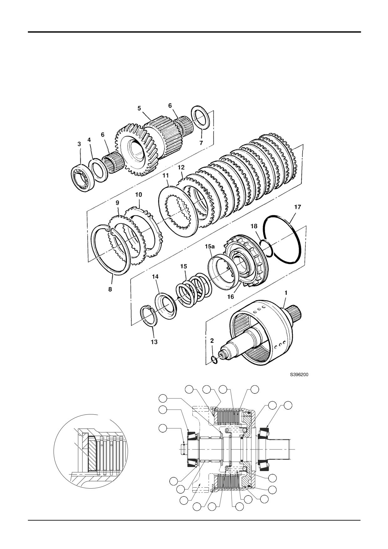
Using a puller or press, withdraw the 4WD gear and
splined hub 5, together with its bearing 3, needle roller
bearings 6 and thrust washer 4. Remove thrust washer
13
7. (Note that thrust washers 4 and 7 are not
interchangeable).
4
Remove the clutch friction/counter plates retaining
circlip 8.
5
Remove pressure end plate 10 and shim 9, if fitted.
6
Remove the clutch friction plates 11 and counter plates
12. Keep them together in sets, DO NOT mix the plates
A401360
with those from other clutches.
7
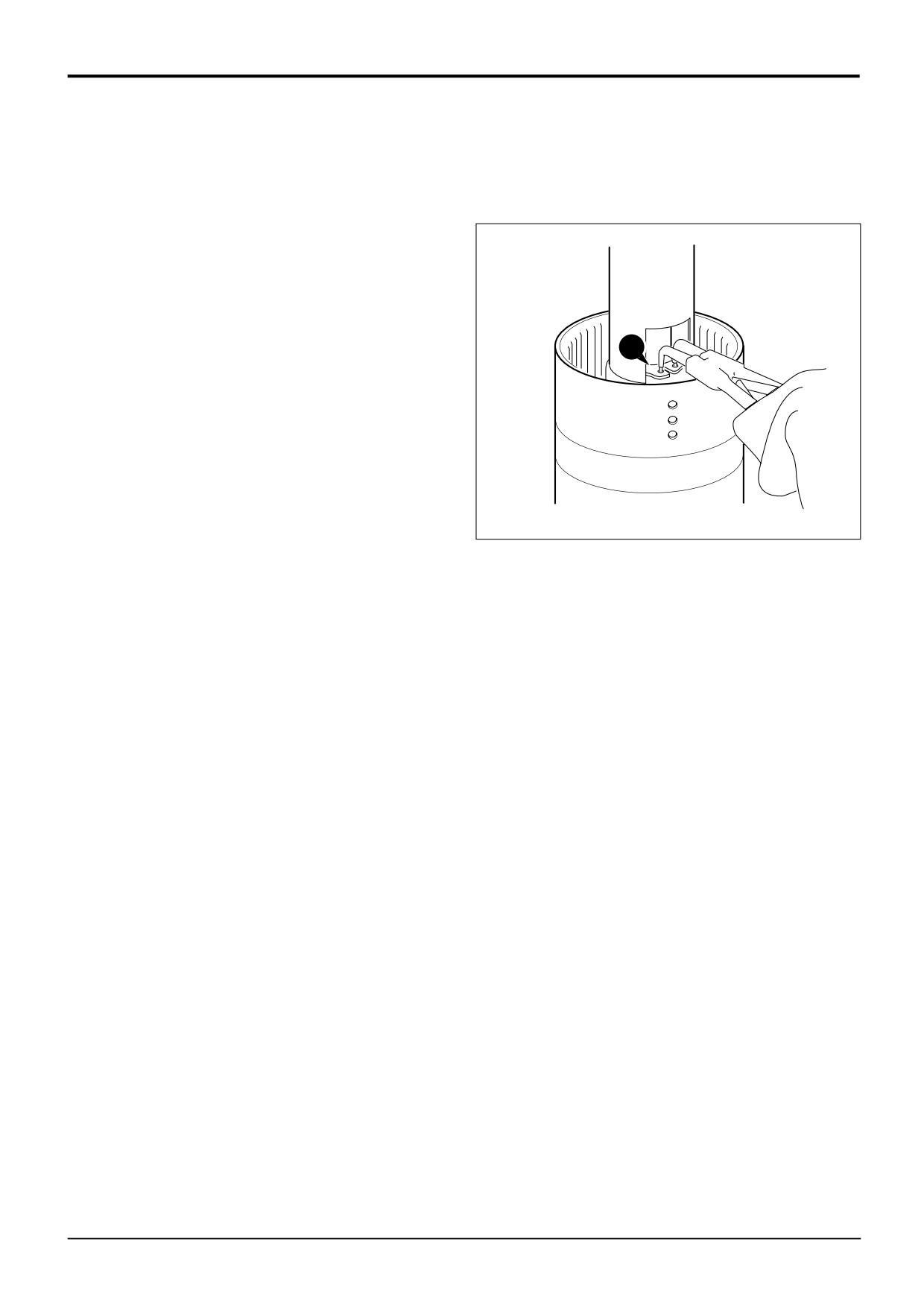
Position clutch assembly in a suitable press, with a cut
away tube compress the piston spring as shown, then
remove circlip 13.
8
Lift off spring retaining plate 14.
9
Remove the spring 15 and oil baffle 15A.
10
Turn the assembly over and knock the clutch shaft on a
piece of aluminium (or wood) to loosen the piston 16.
Note: If the piston does not loosen when the clutch shaft is
knocked on aluminium, then hand pump air down the shaft oil
inlet hole.
11
Remove the piston 16. Remove and discard the piston
'O' ring 17 and shaft 'O' ring18.
9803/3280
Issue 1
Section F
Transmission
Section F
134 - 3
Powershift Gearbox
134 - 3
PS 760 - 2/4WD Clutch (Pressure ON) - Assembly
10
9
12
11
7
18
1
3
A
8
2
10
15a
4
6
17
5
15
16
8
14
13
A396260
9803/3280
Issue 2*
Section F
Transmission
Section F
134 - 4
Powershift Gearbox
134 - 4
PS 760 - 2/4WD Clutch (Pressure ON)
- Assembly
Visually inspect the friction and counter plates:
9
Fit thrust washer 7.
Counter plates - light scoring/polishing is permissible,
10
Carefully align the teeth of the clutch plates using a thin
plates that are not flat, worn or heavily marked or
rod (or screwdriver) and fit the 4WD gear and splined
scored must be replaced with a new set.
hub 5, needle roller bearings 6 and thrust washer 4.
Friction plates - the cross hatching should be clearly
11
Smear the clutch end bearing 3 with gearbox oil and
visible, plates that are not flat, have friction material
press the bearing onto the shaft to seat on thrust
damage or scoring must be replaced with a new set.
washer 4.
DO NOT mix old, new and worn plates, if a plate is
12
Fit piston ring seal 2, refer to Piston Ring Seals -
damaged/worn fit a complete new set.
Fitting Procedure.
Needle roller bearings should slide into position freely, do not
bend or distort the cage to fit. If the cage has been distorted
fit new bearings.
Note: The piston incorporates a small check valve. Visually
inspect the piston to ensure the ball is in place and that the
seat is free from contamination. If necessary clean the valve
by blowing through with an air line. DO NOT use a wire rod
(or screwdriver) as damage to the valve seat could occure.
1
Fit new 'O' rings 17 and 18. Lubricate the piston 16 with
oil and press fully into bore of clutch housing.
2
Fit oil baffle 15A, piston spring 15, make sure the spring
seats in the piston.
3
Fit the spring retaining plate 14.
4
Compress the spring and secure with circlip 13.
5
Fit one counter plate 12 followed by one friction plate
11. Continue fitting alternate counter and friction plates,
finishing with a friction plate.
* 6
Fit the pressure end plate 10, do not fit shim 9 at this
stage. Make sure that the chamfered face is fitted
facing the clutch pack as shown at A. Make sure the
teeth are not aligned with the lubrication slots in the
housing.
7
Fit the clutch friction/counter plates retaining circlip 8.
8
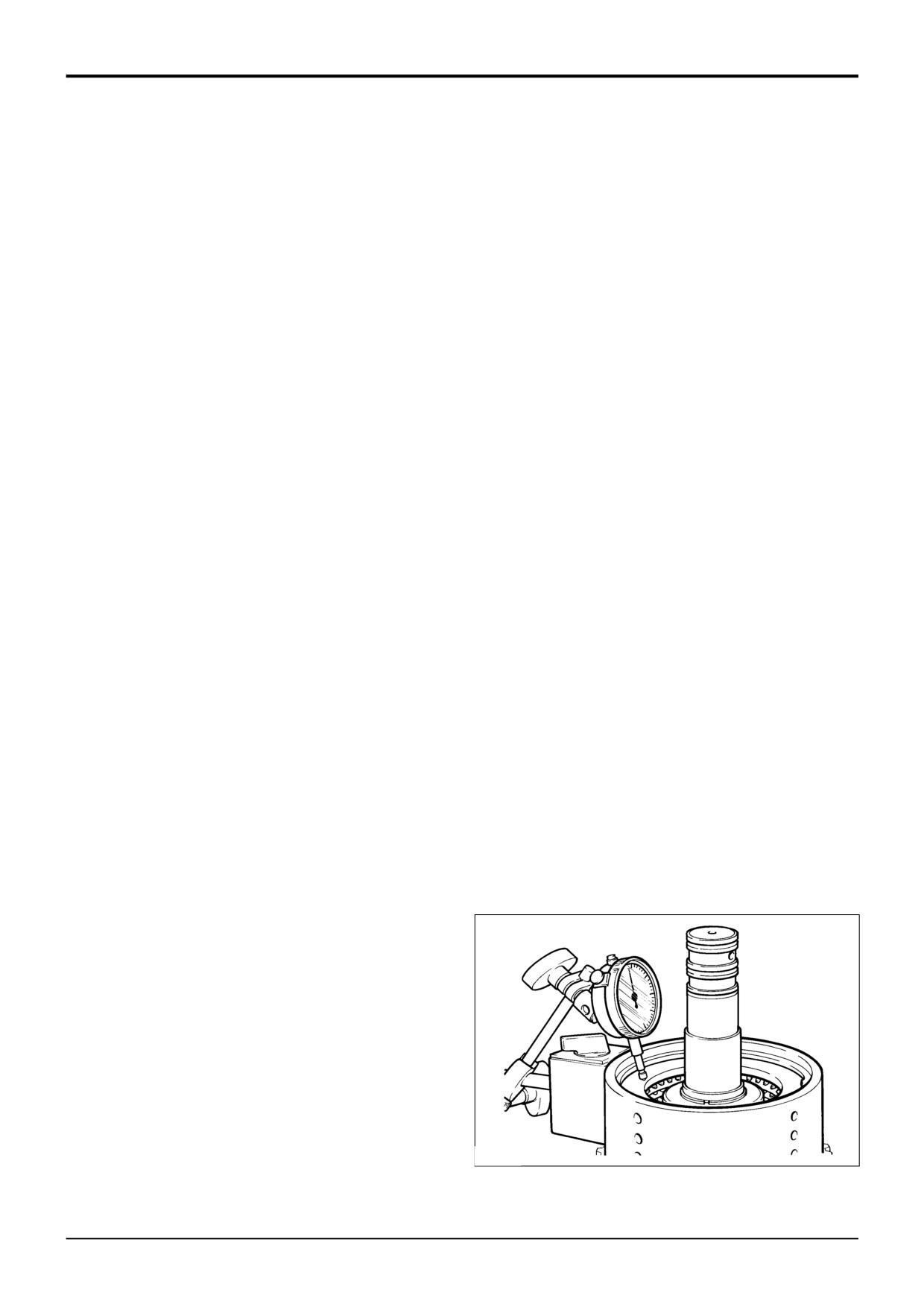
Using a dial test indicator as shown, measure the end
float of the pressure end plate 10, which should be 1.9
to 2.5 mm (0.075 to 0.098 in).
If it is necessary to adjust the end float to bring it within
tolerance, there is a choice of fitting a 6.0mm (0.23in) or
6.5mm (0.25in) thick pressure end plate 10, with either a
shim 9 or an extra counter plate 12 between the
retaining circlip 8 and pressure end plate 10.
Use an airline to check the operation of the clutch.
217590
9803/3280
Issue 2*
Section F
Transmission
Section F
140 - 1
Powershift Gearbox
140 - 1
Polytetrafluoroethylene (PTFE) Piston Ring Seals - Fitting Procedure
See Synchro Shuttle Gearbox, Piston Ring Seals - Fitting
Procedure.
9803/3280
Issue 1
Section F
Transmission
Section F
150 - 1
Torque Converter
150 - 1
Torque Converter
Removal
See the relevant gearbox removal procedure for torque
11
Rotate the flywheel until the next bolt hole is
converter removal.
accessible, fit and hand tighten the next bolt 3. Repeat
the operation until all bolts are fitted. Finally torque
tighten bolts 3 to 44 Nm (32 lbf ft), rotating the flywheel
Replacing
Ensure that flywheel face, drive plate, and hardware are
each time to align bolts 3 with access hole. Refit
clean and free from burrs or other surface imperfections.
access plate.
When Replacing
1
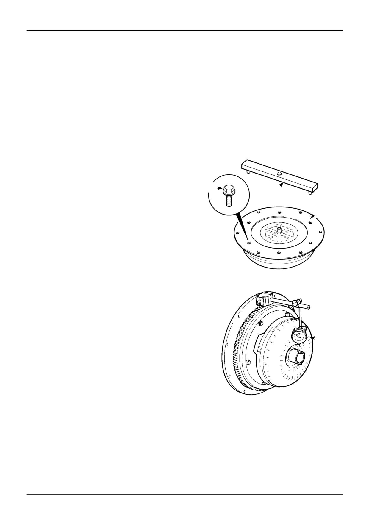
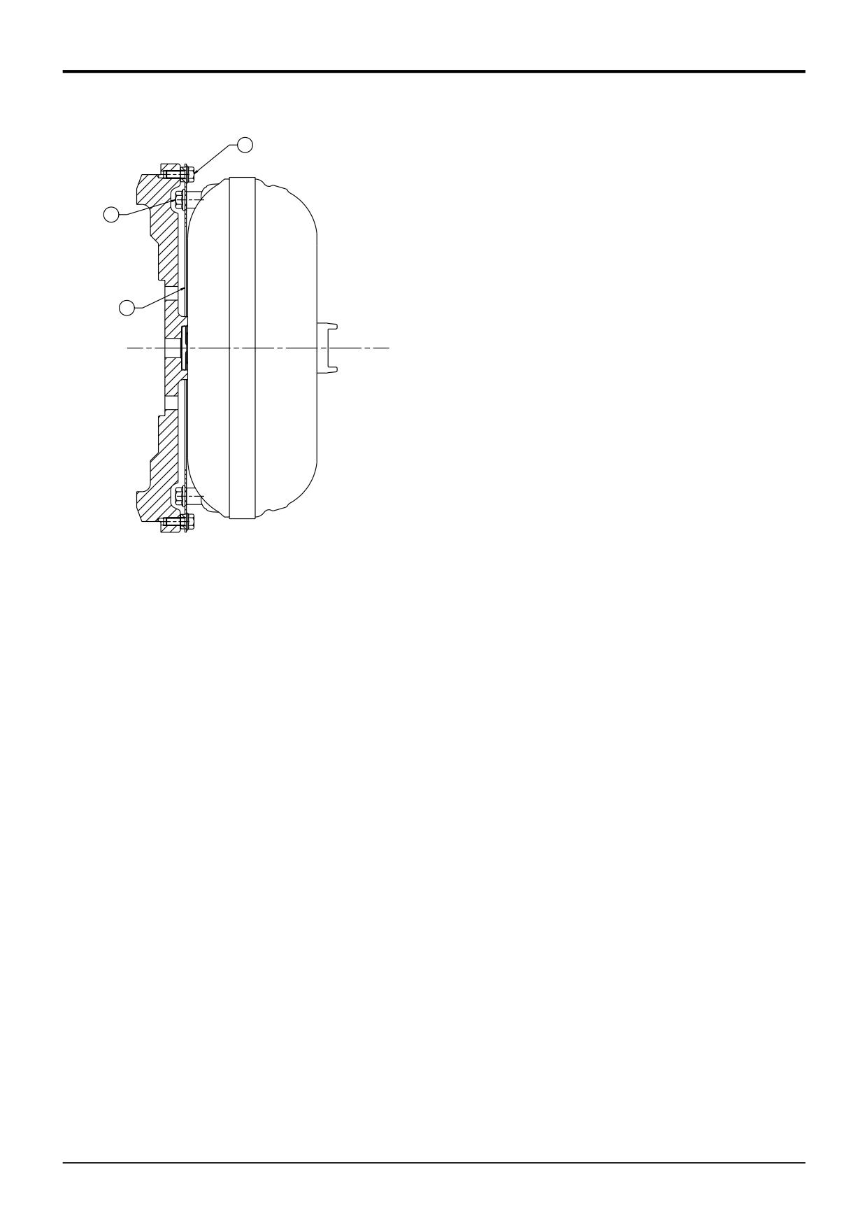
Offer drive plate 1 to the torque converter.
2
Place the torque converter alignment tool A over the
torque converter spigot, make sure that the tool locates
in two of the converter bolt holes as shown. It is
important to note that the converter drive tube must be
protected against damage or contamination at all times.
3
Fit four of the M10 flanged bolts 2 and torque tighten to
2
A
84 Nm (62 lbf ft). Remove the alignment tool and fit the
remaining two retaining bolts 2.
1
4
Offer the torque converter and drive plate assembly to
the flywheel, bolt the drive plate to the flywheel (use
only 3 bolts). Check the converter run-out as shown at
B, which should not exceed 0.38mm (0.015 in.).
Note: In the unlikely event that the run-out exceeds 0.38 mm
S267910
(0.015 in.), remove the converter and check the spigot for
burrs, remove the drive plate and rotate it 180° on the torque
converter, repeat steps 2 to 4.
5
Remove the torque converter and drive plate assembly
from the flywheel.
6
Install the torque converter with its drive plate assembly
onto the transmission input shaft, make sure that the
dogs on the converter pump drive shaft engage with
the recesses in the pump, also take care not to damage
the oil seal.
B
7
Rotate the engine flywheel so that one bolt hole is in a
six O' clock position.
8
Rotate the torque converter and drive plate assembly
so that one bolt hole is in a six O' clock position.
9
Install the transmission/torque converter assembly to
S161470
the engine. See the relevant gearbox replacement
procedure. It is vitally important that the torque
converter is fitted at the gearbox and engine
flywheel correctly. Failure to locate the converter
correctly will result in damage to the gearbox oil pump
on engine start up.
10
Remove the access plate from the bottom of the engine
flywheel housing and through the access hole fit and
hand tighten one M8 flanged bolt (item 3) in the six 'O'
clock position
9803/3280
Issue 1
Section F
Transmission
Section F
150 - 2
Torque Converter
150 - 2
3
2
1
A265990
9803/3280
Issue 1
Section G
Brakes
Section G
i
i
Contents
Page No.
Technical Data
System type
2 - 1
Basic System Operation
Compensating Master Cylinder - Description
3 - 1
Pedals Locked - Normal Operation
3 - 1
Pedals Locked - Compensating Operation
3 - 1
Pedals Unlocked - Normal Operation
3 - 1
Fault Finding
10 - 1
Service Procedures
Service Brakes
- Brake Light Switch - Adjustment
20 - 1
- Brake Piston Seal Leakage Test
20 - 2
Parking Brake
- Testing
20 - 3
- Adjustment
20 - 4
- Switch Adjustment
20 - 5
- Renewing the Brake Pads
20 - 6
Master Cylinder and Servo Unit
Removal and Replacement
30 - 1
Dismantling and Assembly
30 - 3
Service Brakes
Dismantling and Assembly
40 - 1
Bleeding
40 - 2
Parking Brake
Torque Figures
50 - 1
Calliper Removal and Replacement
50 - 2
Calliper Dismantling and Assembly
50 - 3
Brake Disc - Removal and Replacement
50 - 7
9803/3280
Issue 1
Section G
Brakes
Section G
2-1
Technical Data
2-1
System Type
Hydraulic servo assisted service brakes in rear axle only, operated from
* separate pedals. Independant cable operated parking brake in the drive to
the rear wheels.
Service Brake
Type
JCB Oil-immersed multi-plate disc
Actuation
Hydraulic - vacuum servo assisted
Location
Rear axle centre casing (2 brake packs)
Friction Plates (5 per brake pack)
Outside Diameter
220 mm (7.992 in)
Inside Diameter
160 mm (6.299 in)
Nominal Facing Area per Plate
18603 mm2 (28.8 in2)
Hydraulic Piston Diameter
216 mm (8.5 in)
Master Cylinder (combined servo assistance)
Number of Cylinders
2
Type
Compensated master cylinder
Piston Diameter (each)
22.22 mm (0.875 in)
Parking Brake
Type
Disc brake, manually adjusted calliper
Actuation
Cable operated
Location
* Mounted on the rear axle drive head.
Disc Diameter
279.4 mm (11 in)
Note: Because the service brakes are located in the rear axle, instructions for dismantling and assembly are shown in Section
F - Rear Axle Brakes.
9803/3280
Issue 2*
Section G
Brakes
Section G
3 - 1
Basic System Operation
3 - 1
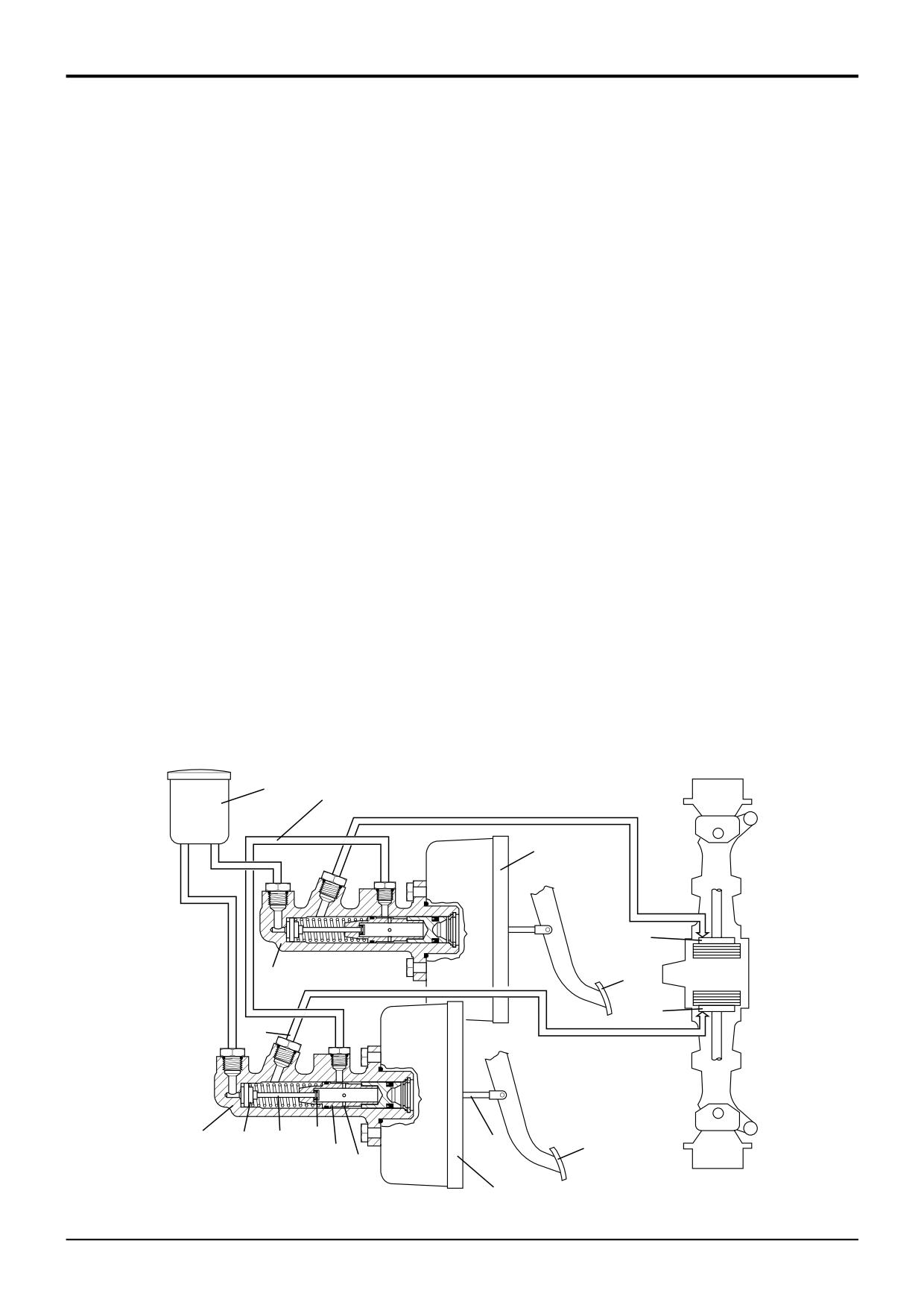
Compensating Master Cylinder
Pedals Locked - Compensating Operation
When the brake pedals are pushed down (the brake pedals
are mechanically locked together), actuation of the brake
Description
packs H and H1 is as described in Pedals Locked - Normal
Compensating master cylinders overcome the problem of
Operation. If however, the brakes have not worn equally,
unequal wear between the right and left brake. The units
then the amount of fluid displaced from each master
incorporate both master cylinder and compensating valve.
cylinder will vary and some form of compensation is
required.
Each brake has its own master cylinder A, A1, brake pedals
B, B1, servo units N, N1 and associated pipework. Both
Pedal application moves plungers E down the bores of
master cylinders have one common reservoir C.
master cylinders A and A1. Linings of brake H are brought
into contact before the linings of brake H1 because they
Note: Dual pedal braking is applicable only to 2WS
have not worn as severely.
machines. 4WS machines have a single brake pedal.
If further displacement took place at the linings, brake H
Pedals Locked - Normal Operation
would be applied before brake H1. Therefore master
When the brake pedals are pushed down (the brake pedals
cylinder A begins to compensate for master cylinder A1.
are mechanically locked together), rod D pushes the plunger
E down the bore of the master cylinder. Pressurised oil
Fluid is displaced from A to A1 via bridge pipe M until the
acting on centre valve seal F via valve stem G causes the
pressures are equalised. In this condition both
seal to close off the reservoir supply port. As the plunger
compensating valves are open and both brakes are applied
continues to move down the bore, pressurised oil flows to
evenly.
the brake pack H via service port J and the associated
pipework.
Pedals Unlocked - Normal Operation
When a single brake pedal is pushed down, rod D pushes
Master cylinder A1 operates in the same way to feed brake
the plunger E down the bore of the master cylinder.
pack H1.
Pressurised oil acting on centre valve seal F via valve stem
G causes the seal to close off the reservoir supply port. As
With valve stem G at maximum travel, further movement of
the plunger continues to move down the bore, pressurised
plunger E causes valve K to lift off its seat. Both master
oil flows to the brake pack H via service port J and
cylinders are interconnected via bridge pipe M, therefore
associated pipework, thus braking one wheel only.
hydraulic pressure in both cylinders will be equal.
With valve stem G at maximum travel, further movement of
If the brake packs H and H1 have worn equally, then the
plunger E causes valve K to lift off its seat. Fluid is
amount of oil displacement between cylinders will be
displaced through drillings P from the active cylinder A via
minimal and the brakes will be applied evenly.
bridge pipe M to passive cylinder A1. Valve K1 in the
passive cylinder is held on its seat by the displaced
pressurised fluid.
C
M
N1
H1
A1
B1
H
J
A
K
F
G
D
B
E
P
N
A265570
9803/3280
Issue 1
Section G
Brakes
Section G
10 - 1
Fault Finding
10 - 1
Brake System
Note: The brakes generate a high temperature when operating, this means that the casing will be hot to touch, this condition
is normal. Note aslo that 4WS machines do not have dual pedal braking.
FAULT
POSSIBLE CAUSE
ACTION
A
One or both brakes do not apply.
1
Master cylinder fault.
1
Check master cylinder in single and
(Brake travel not excessive, brakes
coupled pedal modes to identify fault
not pulling to one side).
area, service as required.
2
Friction/counter plate distortion.
2
Check friction/counter plates.
B
Pedal travel excessive (but not
1
Air in hydraulic system.
1
Check fluid reservoir level. Check for
touching floor).
fluid/air leaks, rectify as required.
2
Leak in hydraulic system.
2
Check for fluid loss at master
cylinder and brake piston, all pipes
and fittings for loose connections.
Rectify as required.
3
Friction/counter plate distortion.
3
Renew friction/counter plates
-
BOTH sides.
C
Applying one brake (pedals
1
Valve stem seal inside (non-active)
1
Renew master cylinder piston.
unlocked) also partially engages
master cylinder piston not sealing.
the other brake.
D
Pedal hard to operate.
1
Tightness at pedal pivot.
1
Inspect
pedal
pivot.
Free-
off/lubricate.
2
Fluid contamination/seal damage.
2
Flush system and renew all hydraulic
seals.
3
Misaligned push rod/pedal.
3
Check and rectify as required.
4
Kinked or crushed brake pipes.
4
Check/renew brake pipework.
Items 5 to 7 are for machines fitted
with servo assisted brakes only:
5
Vacuum failure due to low vacuum
5
Inspect/service engine mounted
at source.
exhauster unit as required.
6
Blocked/leaking vacuum pipe.
6
Check/renew vacuum pipe.
7
Servo defect.
7
Renew servo unit.
E
Pedals touch floor under constant
1
Master cylinder fault.
1
Check master cylinder in single and
pressure - no fluid loss.
coupled pedal modes to identify fault
area, service as required.
2
Friction/counter plate distortion.
2
Renew friction/counter plates
-
BOTH sides.
3
Air in hydraulic system.
3
See item B.1.
F
Pedals touch floor under constant
1
External fluid leaks.
1
Visually check brake circuit for fluid
pressure - and fluid loss.
loss, service as required.
2
Internal fluid leaks.
2
Refer to Service Procedures
-
Brake Piston Seal Leakage Test.
G
Pulling to one side when pedals
1
Compensating
feature
not
1
Inspect
master
cylinder
locked together.
working.
compensating operation. Check if
blockage in bridging pipe. Service as
required.
9803/3280
Issue 1
Section G
Brakes
Section G
10 - 2
Fault Finding
10 - 2
FAULT
POSSIBLE CAUSE
ACTION
G Pulling to one side when pedals
2
Braking system inoperative on
2
Unlatch pedals to test circuits
locked together (cont'd).
one side.
individually.
3
Friction plates worn beyond limits
3
Renew
friction/counter plates
-
or distorted on one side.
BOTH sides.
4
Badly adjusted push rods.
4
Adjust push rod (1mm minimum).
5
Servo operating rod out of
5
Adjust servo operating rod.
adjustment.
6
Annular piston fault (see item J6).
6
See item J6.
H Poor braking (not pulling to one
1
Friction plates worn beyond limits
1
Renew
friction/counter plates
-
side).
or distorted on one side.
BOTH sides.
2
Master cylinder fault.
2
Check master cylinder in single and
coupled pedal modes to identify fault
area, service as required.
3
Annular piston fault (see item J6).
3
See item J6.
4
Incorrect/low axle oil.
4
Fill axle with correct type of oil.
5
Vacuum failure (machines fitted
5
Inspect vacuum
source/pipes,
with servo assisted brakes only).
service as required.
J One or both brakes not releasing.
1
Brake pedal spring fault.
1
Fit a new spring.
2
Master cylinder fault (plunger
2
Service as required.
stuck in bore).
3
Blocked hole in master cylinder
3
Fit a new reservoir cap.
reservoir cap.
4
Brake pedal free travel incorrect.
4
Adjust pedal free travel.
5
Fluid contamination/seal damage.
5
Flush system and renew hydraulic
seals.
6
Annular brake piston(s) binding in
6.1
Check that correct brake fluid has
axle.
been used (incorrect fluid could swell
the annular brake piston seals).
6.2
Check if annular brake piston seals
in good condition.
6.3
Check that annular brake piston
rotates freely in its housing with no
seals fitted.
6.4
Check that the annular brake piston
seal
retracts
the
piston
approximately 0.5mm (0.020 in).
7
Kinked or crushed brake pipes.
7
Check and renew pipes as required.
8
Friction/counter plates not free on
8
Check friction/counter plates for free
splines and/or dowels.
movement, replace if required
-
BOTH sides.
9803/3280
Issue 1
Section G
Brakes
Section G
10 - 3
Fault Finding
10 - 3
FAULT
POSSIBLE CAUSE
ACTION
K Poor braking when hot.
1
Moisture in system vapourizing
1
Strip axle and clean annular piston to
when axle is hot.
remove moisture. Remove master
cylinders and check for corrosion,
service as required. Flush hydraulic
brake system.
L Excessive brake noise in operation.
1
Deterioration of axle oil or wrong
1
Change axle oil.
type of axle oil.
Note: Due to the metal to metal contact
of oil immersed brakes, limited noise
2
Axle oil loss.
2
Refill axle with correct oil and check
can be heard which is consistent with
for leaks.
this type of design - this is normal.
3
Friction plates worn beyond limits.
3
Renew friction/counter plates.
4
Friction/counter plates in poor
4
Check for distortion or surface
condition.
pitting
and/or roughness of
friction/counter plates (annular
grooving of counter plates is
acceptable).
M Fluid loss when machine standing,
1
Slight cut or nick in the brake
1
Strip axle, replace seal.
for instance - overnight (see note).
piston seal, refer to Service
Procedures - Brake Piston Seal
Note: Confirm fault is as indicated by
Leakage Test.
checking that the pedals DO NOT touch
floor under constant pressure.
9803/3280
Issue 1
Section G
Brakes
Section G
20 - 1
Service Procedures
20 - 1
Service Brakes
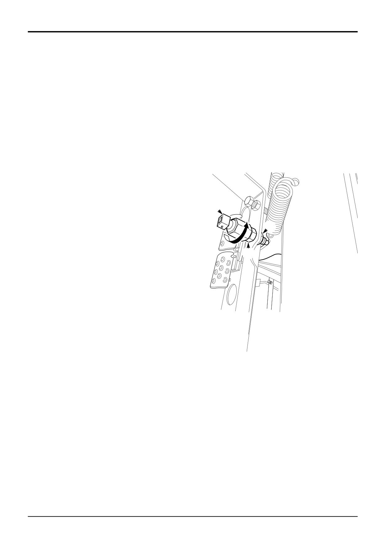
Brake Light Switch - Adjustment
1
Select the starter key switch to the ON position, do not
start the engine.
2
With the brake pedal in the return position, adjust
locknuts B and use feeler gauges to set the proximity
switch A so that there is clearance of 2mm MIN - 3mm
MAX between the end of the switch and the brake
pedal lever. The light emitting diode (L.E.D.) on the
switch should be illuminated.
3
Secure the switch in position by tightening locknuts B.
4
Depress the brake pedal and check the correct
operation of the brake lights.
Torque Settings
Item
Nm
kgf m
lbf ft
A
B
29
2.95
21
B
B
9803/3280
Issue 1
Section G
Brakes
Section G
20 - 2
Service Procedures
20 - 2
Service Brakes
5
Repeat steps 1 to 4 for the opposite brake piston seal.
6
Reconnect all brake pipes and bleed the brake system.
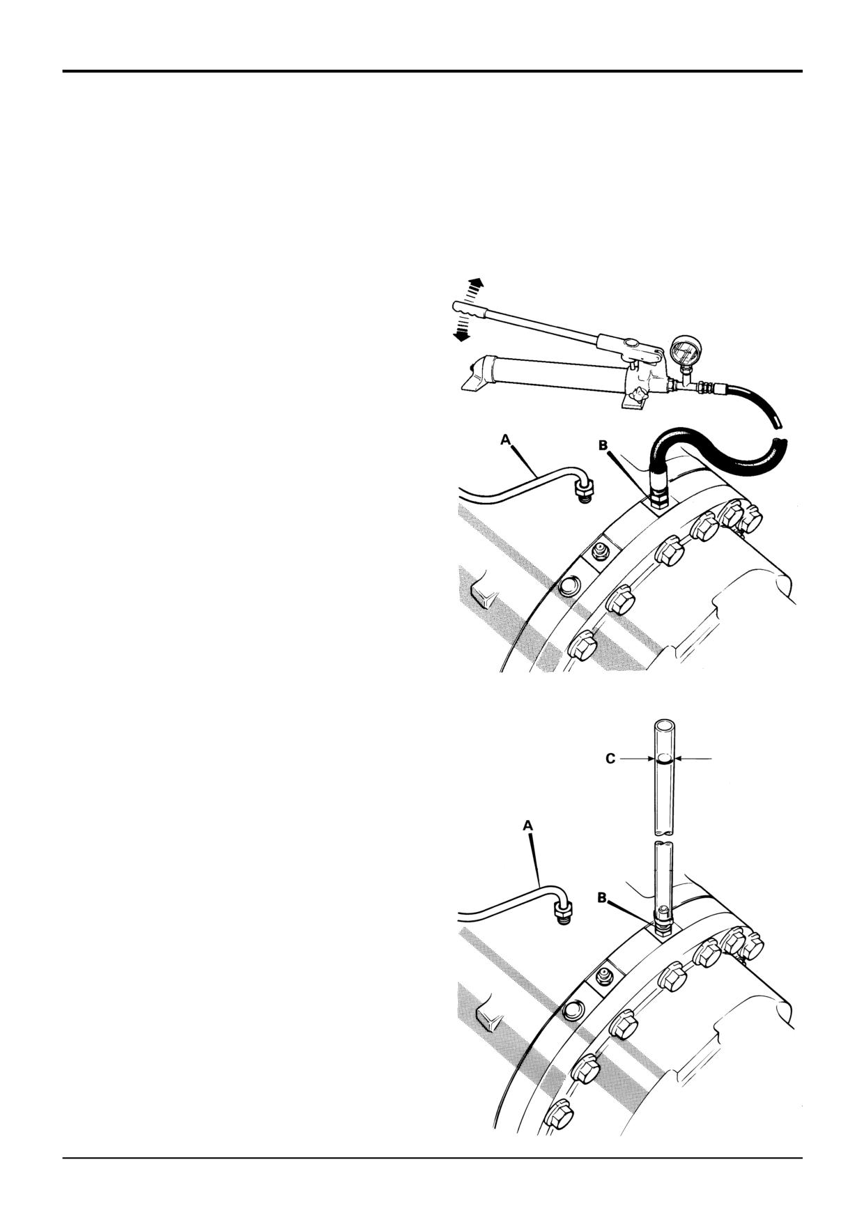
Brake Piston Seal Leakage Test
Refer to Service Brakes - Bleeding.
The following procedure explains how to check if a brake
piston seal is severely damaged/perished or if the seal has a
small cut or nick. The test must only be done when the axle
is COLD.
! WARNING
X
Before working on the brake system make sure the
machine is on level ground and chock all four wheels.
BRAK 1-4
! WARNING
Do not drive the machine with any part of its brake
system disconnected. When the following test has been
completed reconnect all brake pipes and bleed the brake
system using the recommended procedure.
BRAK 2-1
1
Remove and cap brake piston feed pipe A.
2
Fill the brake piston housing with JCB Light Hydraulic
Fluid.
3
Check for severe piston seal damage:
a Install a hand pump fitted with a 0 - 40 bar (0 - 600
lbf/in2) pressure gauge to port B, as shown at X.
Note: The hand pump MUST be filled with JCB Light
Hydraulic Fluid. DO NOT exceed 69bar (1000 lbf/in2).
159830X
b Use the hand pump to generate a pressure in the
brake piston housing.
c If the pressure falls off rapidly, or if no pressure
reading can be obtained, the seal is severely
Y
damaged and needs replacing with a new one.
4
Check for small cuts or nicks in the piston seal:
a Install an adapter fitted with a piece of clear tube to
the brake piston port B, as shown at Y.
Note: The tube must be kept vertical during the test, use
tape to attach the tube to the side of the machine.
b Fill the tube until approximately three quarters full
with JCB Light Hydraulic Fluid
c Using a suitable pen, mark the level line of the
brake fluid on the tube, as shown at C.
d After approximately 1/2 hour, check if the level has
dropped below the original marked line, if it has
then check the brake piston seal for slight nicks,
cuts or generally for wear.
159830Y
9803/3280
Issue 1
Section G
Brakes
Section G
20 - 3
Service Procedures
20 - 3
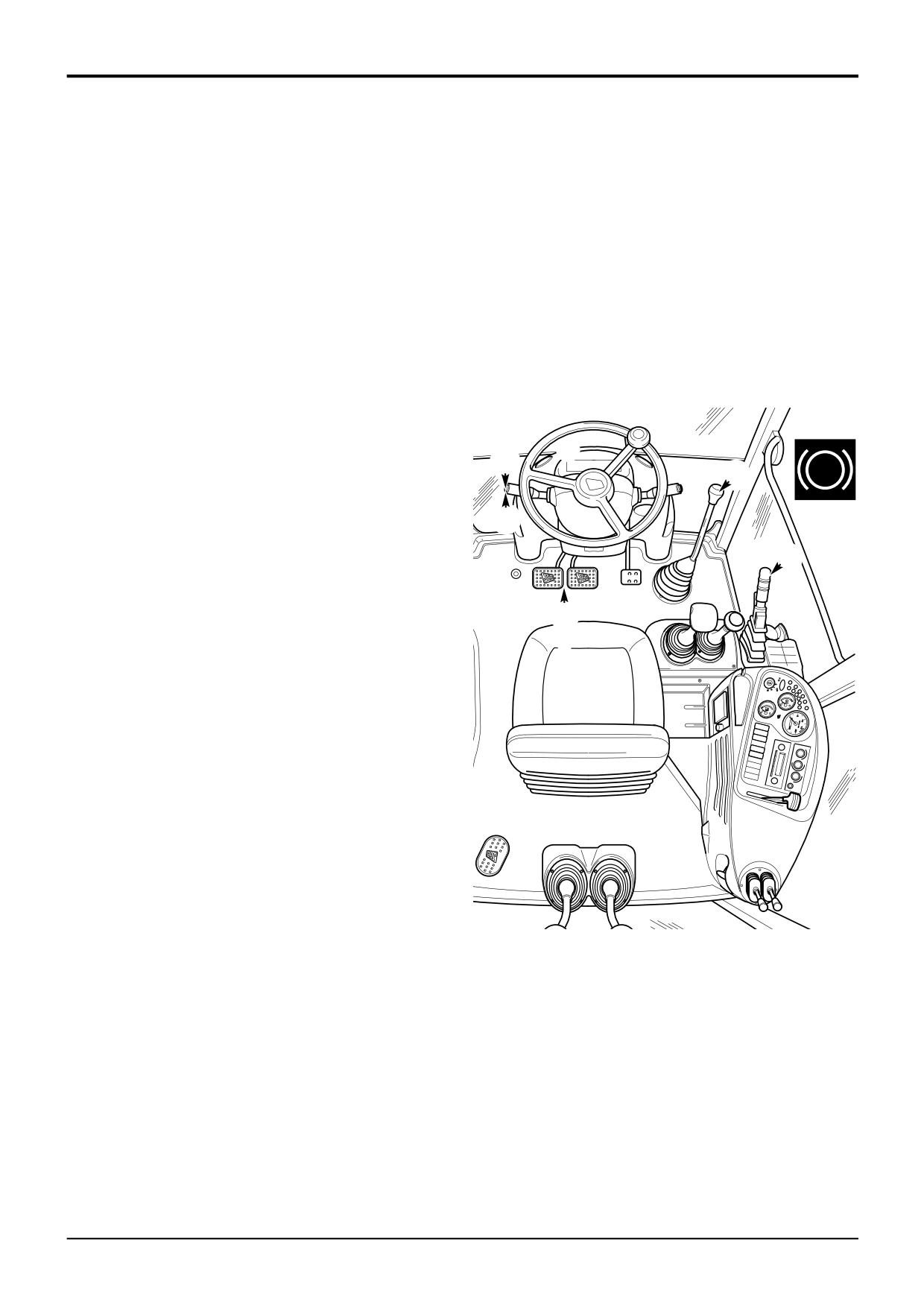
Parking Brake - Testing
If you have any queries concerning this test procedure or
SAFETY NOTICE: Ensure all routine health and safety
parking brake adjustment, consult your local JCB distributor.
precautions are observed before operating machines.
! WARNING
! WARNING
Do not use a machine with a faulty parking brake.
Before testing the parking brake make sure the area
3-2-3-10
around the machine is clear of people.
2-2-4-5
! CAUTION
1
Enter the machine. Fasten your seat belt and park the
Non approved modifications to axle ratios, machine
machine on a level dry surface.
weight or wheel and tyre sizes may adversely affect the
performance of the parking brake.
2
Fully apply the parking brake 1.
3-2-3-11
3
On machines with two brake pedals ensure they are
locked together.
6
4
Start the engine and raise the attachments to the
6
appropriate travelling position.
3
P
2
5
Select fourth gear, 2 for syncro shuttle machines or 3
for powershift machines.
5
6
Push down hard on foot brake pedal 4.
1
7
Select forward drive 5.
! WARNING
4
If the machine starts to move during the following test,
immediately apply the foot brakes and reduce the engine
speed.
2-2-5-1
Test the parking brake as follows:
8
Move the parking brake lever fractionally forward until
the warning light 6 is just extinguished.
9
Slowly release the foot brake pedal 4.
10
If the machine has not moved, use the accelerator
pedal to gradually increase the engine speed to 1500
RPM. The machine should not move.
11
Do not do this test for longer than 20 seconds.
A394410
12
Reduce the engine speed to idle and select neutral 5.
13
Return the park brake lever 1 to the fully on position
from its partially applied position.
14
Lower attachments and stop the engine.
15
If the machine moved during this test, adjust the
parking brake and repeat the test. See Service
Procedures, Parking Brake - Adjustment.
9803/3280
Issue 1
Section G
Brakes
Section G
20 - 4
Service Procedures
20 - 4
Parking Brake - Adjustment
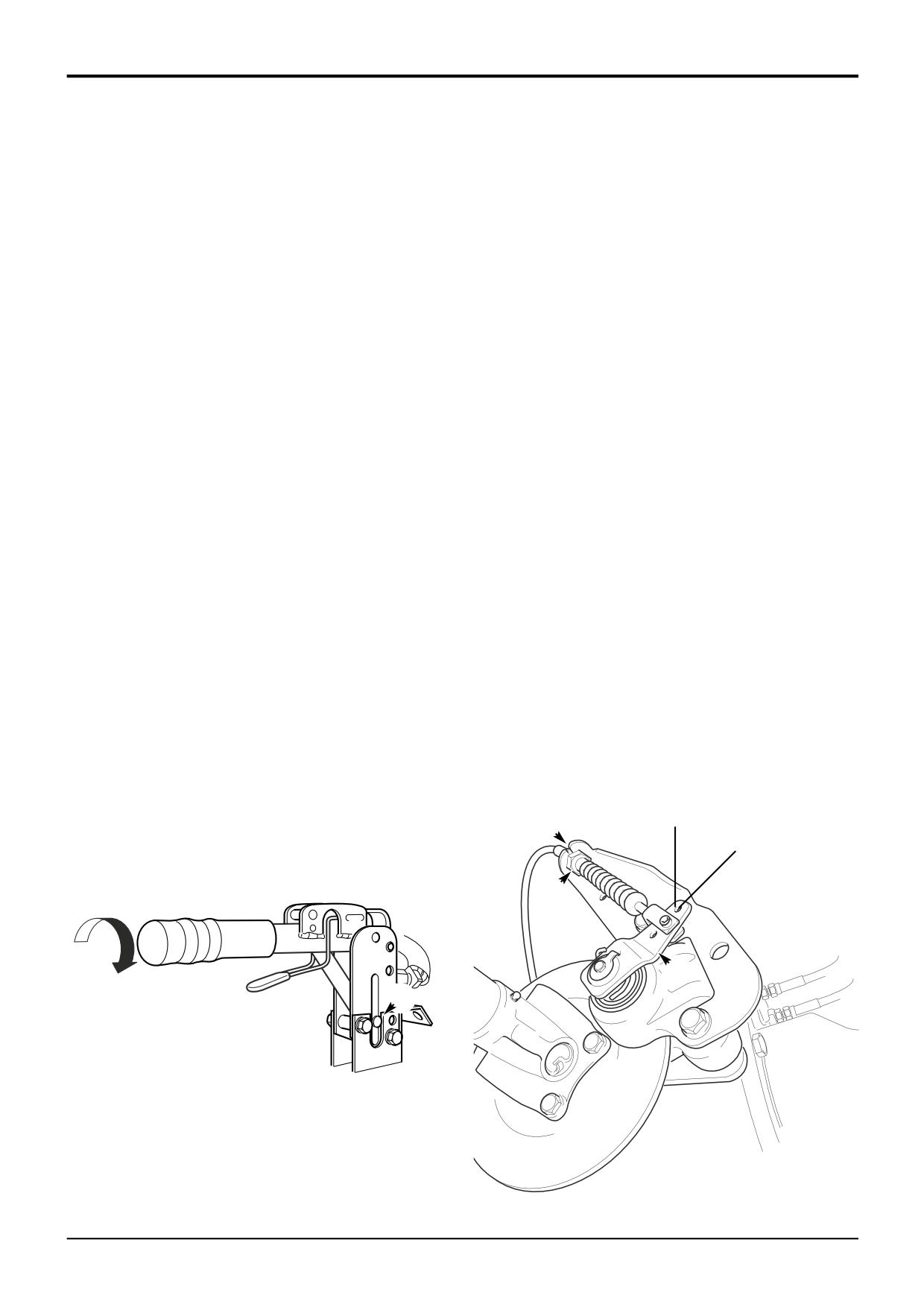
Cable Adjustment
! CAUTION
Adjust the cable at the calliper if there is insufficient
The parking brake must not be used to slow the machine
adjustment at the parking brake lever.
from travelling speed, except in an emergency,
otherwise the efficiency of the brake will be reduced.
If there is no adjustment at the lever or the calliper, change
Whenever the parking brake has been used in an
the brake pads, refer to Parking Brake - Renewing the
emergency, always renew both brake pads.
4-2-1-1/2
Brake Pads.
! WARNING
Always renew a worn or damaged cable.
Before working on the parking brake, make sure that the
1
Disengage the parking brake (lever horizontal).
machine is on level ground. Put chocks each side of all
four wheels. Disconnect the battery so that the engine
2
Turn hand grip E anti-clockwise to centre the pin F in its
cannot be started. If you do not take these precautions
slot.
the machine could run over you.
2-3-2-4/1
3
Release the two locknuts at B and adjust the cable
The parking brake should be fully engaged when the lever is
length to give 10 to 15mm (0.40 to 0.60 in) of caliper
vertical. The parking brake indicator light should light when
lever movement at the outer cable fixing hole H. The
the brake is engaged with the forward/reverse lever away
total clearance between the brake pad to brake disc
from neutral (starter switch at IGN).
should be 0.5 to 0.75 mm (0.02 to 0.3 in).
4
Make sure there is adequate freedom of movement of
! WARNING
operating lever C to ensure a positive brake application,
Over adjustment of the parking brake could result in the
and that the lever returns to the rest position when the
parking brake not fully releasing
parking brake is released.
0011
5
Test the parking brake, refer to Parking Brake -
Lever Adjustment
Testing. Make final adjustments at the park brake lever
if the brake fails the test. Refer to Lever Adjustment.
1
Disengage the parking brake (lever horizontal).
2
Turn handle grip E clockwise, half a turn.
3
Test the parking brake, refer to Parking Brake -
Testing.
4
If the brake fails the test, repeat steps 1, 2 and 3. If
there is no more adjustment and pin F is at the end of
B
its travel adjust the cable.
H
B
C
E
F
A390850
A396181
9803/3280
Issue 2*
Section G
Brakes
Section G
20 - 5
Service Procedures
20 - 5
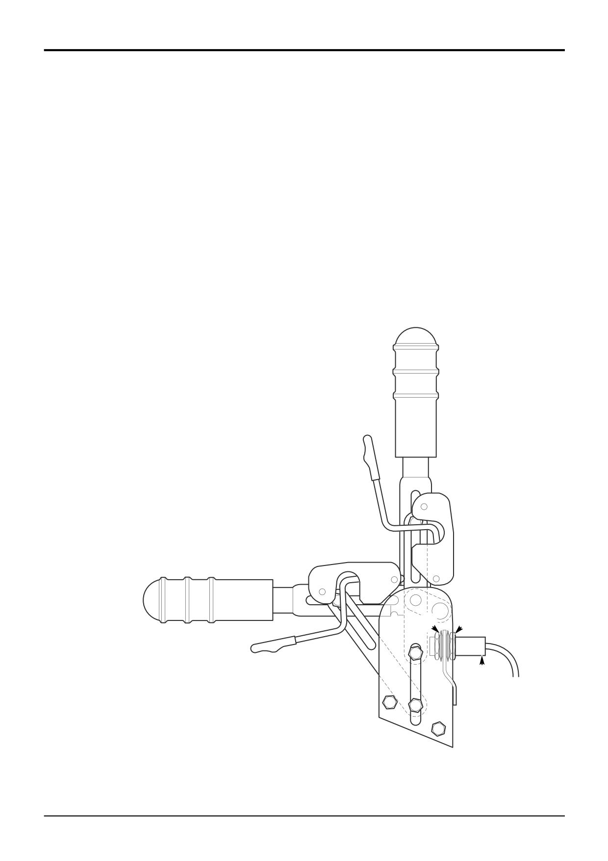
Parking Brake - Switch Adjustment
1
Select the starter key switch to the ON position, do not
start the engine.
2
Select either forward or reverse.
3
Raise the handbrake to the ON position.
4
Adjust locknuts B and use feeler gauges to set the
proximity switch A so that there is clearance of 2mm
MIN - 3mm MAX between the end of the switch and the
handbrake lever. The light emitting diode (L.E.D.) on the
switch should be illuminated and the audible alarm
should sound.
5
Secure the switch in position by tightening locknuts B.
6
Release the parking brake and the audible alarm should
cease.
For adjustment of the Parking Brake, refer to Parking Brake
- Adjustment.
Torque Settings
Item
Nm
kgf m
lbf ft
B
29
2.95
21
B
B
A
A396440
9803/3280
Issue 1
Section G
Brakes
Section G
20 - 6
Service Procedures
20 - 6
Parking Brake - Renewing the Brake Pads
Pad Replacement
1
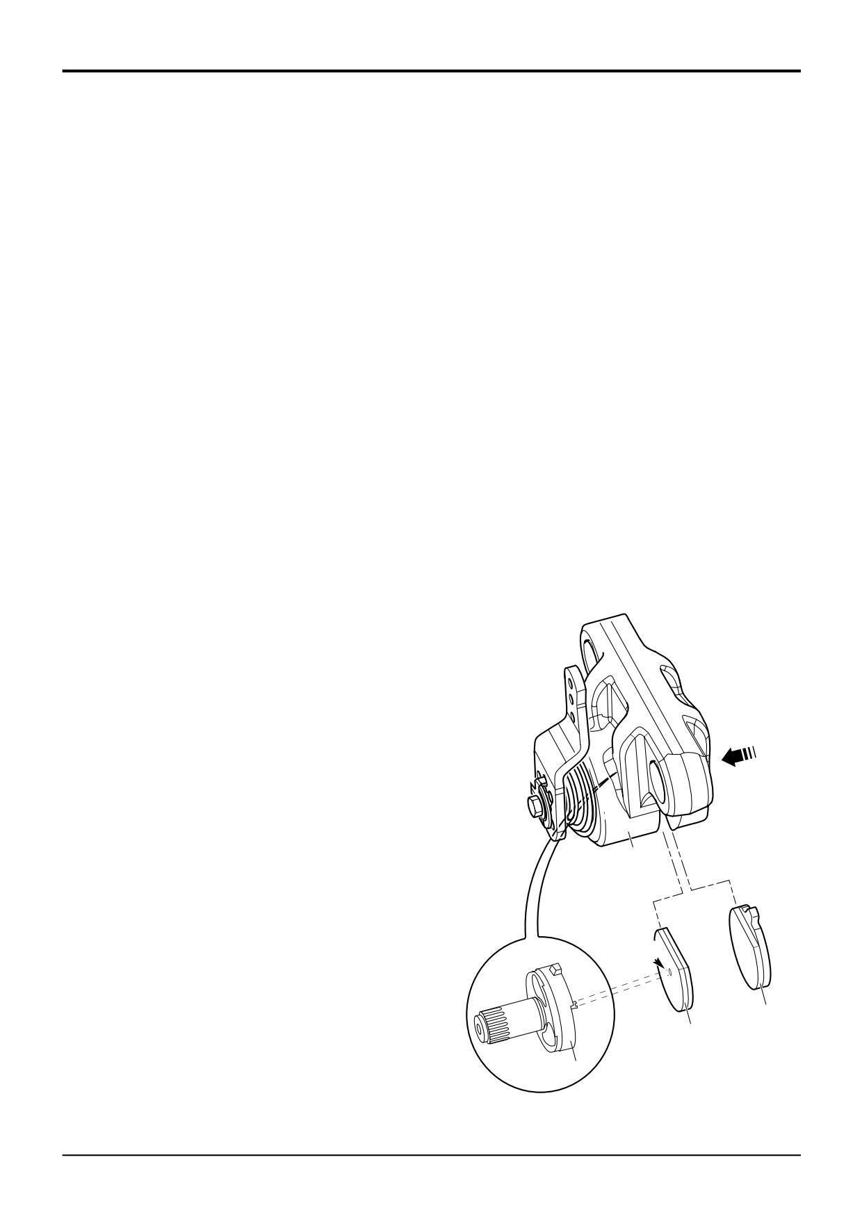
Fit the pad 2 to the lever side of the calliper. Position
! WARNING
the pad inside housing 15. Locate the plastic clip in the
This is a safety critical installation. Do not attempt to do
centre of the rotor 9 into the hole X, and press the pad
this procedure unless you are skilled and competent to
into place.
do so.
2
Fit the pad 1 to the carrier sde of the calliper. Add a
Installation and mounting of the parking brake calliper
small amount of silicon sealant to the back outer edge
requires tightening of the mounting bolts to a specific
of the backing plate to hold the pad in place within the
torque figure. Do not attempt to do this job unless you
housing.
have the correct tools available.
0010
3
Replace the calliper, refer to Parking Brake - Calliper
! WARNING
Removal and Replacement.
Before working on the parking brake, park on level
ground and put chocks each side of all four wheels. Stop
Note: If there is insufficient adjustment after fitting new pads
the engine and disconnect the battery so that the engine
change the brake cable.
cannot be started. If you do not take these precautions
the machine could run over you.
BRAK 8-8
! WARNING
Brake pads generate dust which if inhaled, may
endanger health. Wash off the calliper before
commencing work. Clean hands thoroughly after work.
13-3-1-3
Pad Removal
1
Remove the parking brake calliper from the axle
mounting bracket, refer to Parking Brake - Calliper
Removal and Replacement.
2
Press carrier side pad 1 into housing 15 and remove.
Ensure any residual silicone used for pad retention
during assembly is removed.
3
Carefully lever pad 2 from the rotor inside the housing
using a flat blade screwdriver. Take care to prevent
damage to the plastic clip in the centre of the rotor 9
(there is no need to remove the rotor from the calliper).
Pad Inspection
! WARNING
Oil on the brake disc will reduce brake effectiveness.
Keep oil away from the brake disc. Remove any oil from
15
the disc with a suitable solvent. Read and understand
the solvent manufacturer’s safety instructions. If the
pads are oily, new ones must be fitted.
2-3-2-3/3
1
The minimum thickness of the friction material on either
pad is 1mm (0.04 in), but it is recommended new pads
X
are fitted as pads worn to this limit may not be able to
be adjusted.
1
2
Check the condition of the disc surface. Renew the disc
2
if badly warped, pitted or worn. For brake disc removal,
refer to Parking Brake, Brake Disc - Removal and
Replacement.
9
A390680
3
Renew the cable if worn or damaged.
9803/3280
Issue 1
Section G
Brakes
Section G
30 - 1
30 - 1
G
F
A396450
B
D
E
H
H
E
J
K
327340
9803/3280
Issue 1
Section G
Brakes
Section G
30 - 2
Master Cylinder and Servo Unit
30 - 2
Removal and Replacement
Replacement
! WARNING
Before working on the brake system make sure the
Replacement is a reversal of the removal sequence.
machine is on level ground and chock all four wheels.
BRAK 1-4
Refit the cylinders in their original positions.
Removal
If the brake master cylinders or brake servo units are
1
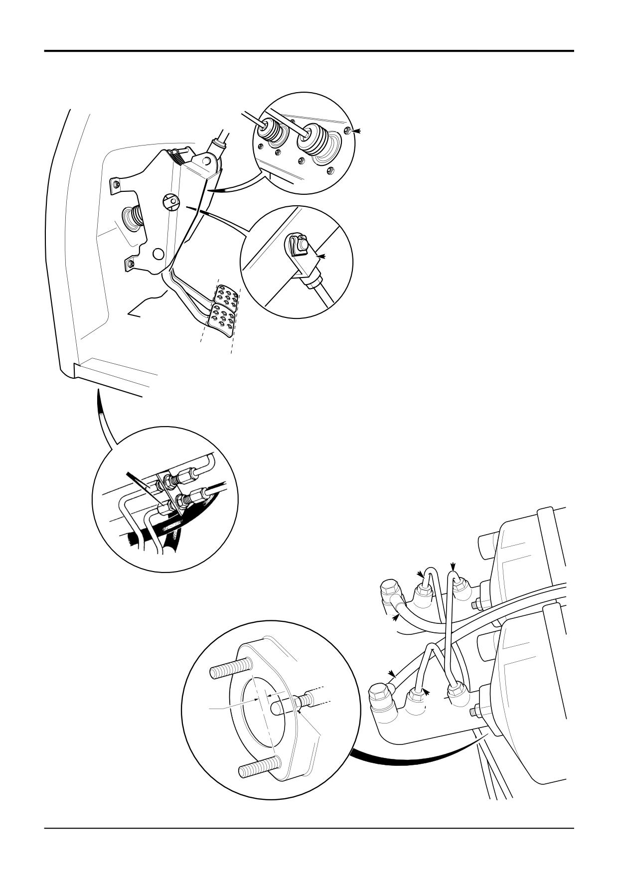
Gain access the the brake pedal box assembly.
removed it is recommended that the servo brake assembly
Remove the steering wheel, column switches and
operating rod measurement is checked.
console assembly. See Section D, Steering Column -
Removal for procedures.
If the rod length is not checked it may result in differing
brake pedal travel which could result in uneven braking.
2
Working outside the cab, loosen and remove brake
pipe unions B, plug and cap to prevent loss of fluid and
1
With the brake master cylinder removed, measure from
ingress of dirt.
the face of the servo unit to the end of the servo brake
rod as shown at J which should be 8.5 to 8.3mm (0.334
3
Remove the brake pipes from the master cylinders:
master cylinders bridging pipe D; axle feed pipes E and
to 0.326in).
reservoir supply pipes H.
2
Adjust measurement J by screwing domed bolt K in/out
4
Working inside the cab, remove the brake pedals clevis
as required, secure in position with JCB Threadlocker &
F and disengage the brake pedal from the servo unit
Sealer.
(both pedals).
Note: If no adjustment is required make sure the domed bolt
5
Loosen and remove the servo unit retaining nuts G
K can not be rotated by finger pressure.
(both units).
! WARNING
6
Tag the cylinders (left and right hand). Remove the
Use of incorrect fluid will cause serious damage to the
master cylinder and servo units.
seals which could in turn cause brake failure.
BRAK 1-1
3
Fill the brake system with JCB Light Hydraulic Fluid and
bleed the system. Refer to Service Brakes - Bleeding.
Note: 4WS machines do not have dual pedal braking.
Procedures described still apply to a single pedal
application.
4
Unlatch pedals and ensure that pedal pads are level
with each other and fully back against their stops.
5
Adjust pedal linkages for free movement to give 1 mm
(0.040 in) on each pushrod.
6
With pedals still unlatched, apply an equal force to each
pedal and check if pedals remain level. If necessary
adjust by increasing the clearance on one of the
pushrods. Do not decrease either clearance below 1
mm (0.040 in).
7
On completion bleed the brake system and check the
brakes operate correctly and that machine stops in a
straight line. Refer to Service Brakes - Bleeding.
8
Latch pedals and check for straight line braking; if
satisfactory straight line braking cannot be achieved
refer to Fault Finding.
Torque Settings
Item
Nm
kgf m
lbf ft
H
30-34
3.0-3.5
22-25
9803/3280
Issue 1
Section G
Brakes
Section G
30 - 3
Master Cylinder and Servo Unit
30 - 3
Dismantling and Assembly
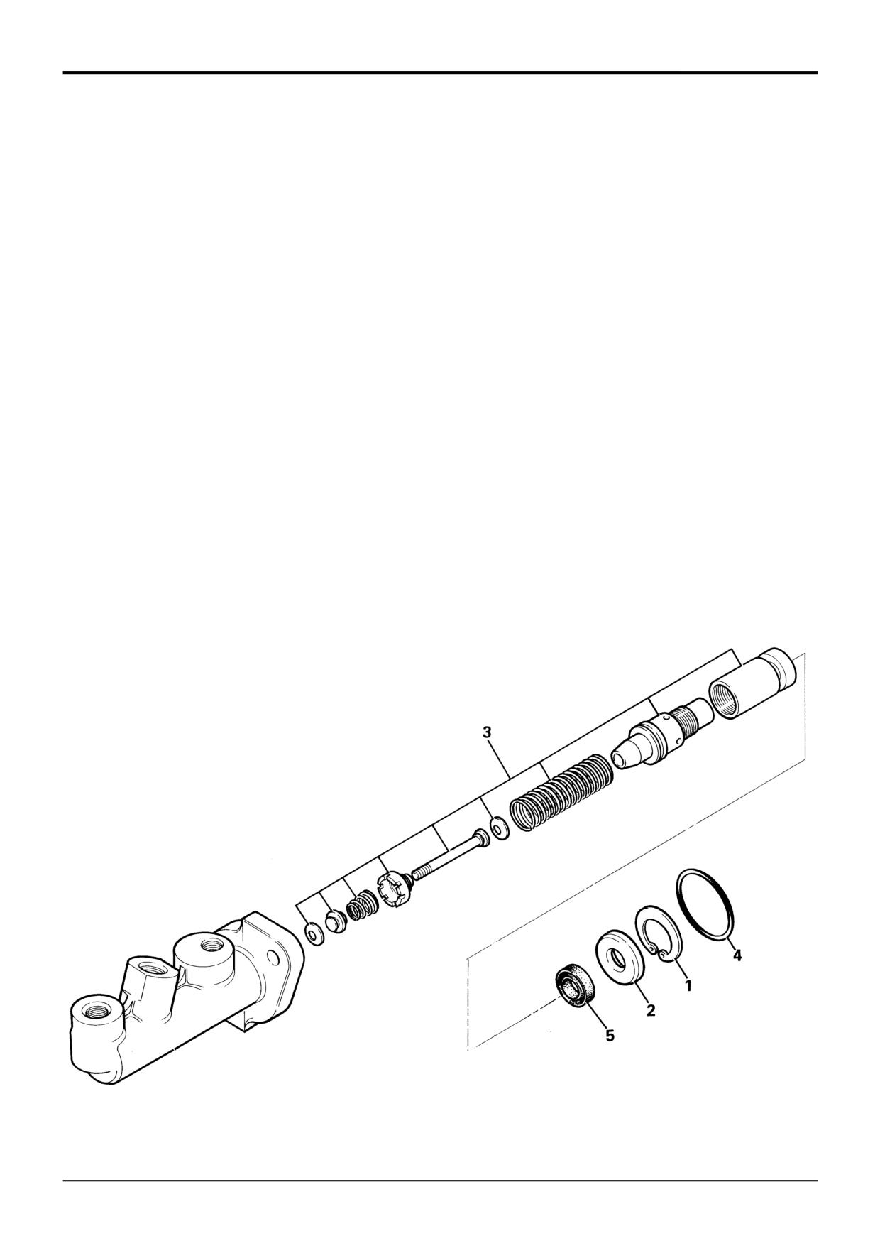
Note 1: The servo unit (not shown) is a non serviceable part.
A faulty servo unit must be replaced with a new one.
Note 2: Seal kits are no longer available for the master
cylinders, the only servicing permitted is a major repair kit
which comprises of a full piston assembly. A faulty master
cylinder and piston assembly must be replaced with new
ones.
Dismantling
Assembly
1
Remove circlip 1 and washer 2.
! WARNING
Use of incorrect fluid will cause serious damage to the
2
Shake the cylinder body, or use compressed air, to
seals which could in turn cause brake failure.
eject piston assembly 3. Take care not to damage the
BRAK 1-1
piston assembly or the bore of the cylinder body.
1
Clean and lubricate all components, including new
3
Examine the working surfaces of piston and cylinder. If
seals, with JCB Special Hydraulic Fluid. DO NOT USE
these are not in perfect condition the master cylinder
CONVENTIONAL BRAKE FLUID OR SERIOUS
assembly must be renewed. The piston assembly 3
DAMAGE WILL BE CAUSED.
cannot be dismantled. If it is damaged (including seal 5),
the complete piston/seal assembly must be renewed,
2
Take care not to damage the machined faces of piston
see Note 2:
assembly 3 when assembling.
S151280
9803/3280
Issue 1
Section G
Brakes
Section G
40 - 1
Service Brakes
40 - 1
Dismantling and Assembly
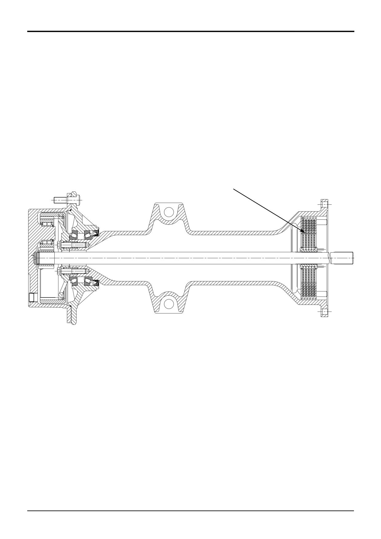
The service brakes are located in the rear axle, as shown at
A. Instructions for dismantling and assembly of the brake are
described in Section F - Rear Axle Brakes.
A
A264180
9803/3280
Issue 1
Section G
Brakes
Section G
40 - 2
Service Brakes
40 - 2
Bleeding
! WARNING
Before proceeding with the bleeding procedure it is
important to ensure that the parking brake is engaged
and that one pair of wheels is blocked on both sides.
BRAK 1-2
! WARNING
Use of incorrect fluid will cause serious damage to the
seals which could in turn cause brake failure.
BRAK 1-1
1
Fill the master cylinder reservoir with the correct fluid,
refer to Section 3 Fluids, Lubricants, Capacities and
Specifications, and ensure that throughout the
bleeding process the level is not allowed to fall below
the MINIMUM mark.
2
Unlatch the pedals, and bleed each brake separately as
follows:
3
Right Hand Master Cylinder
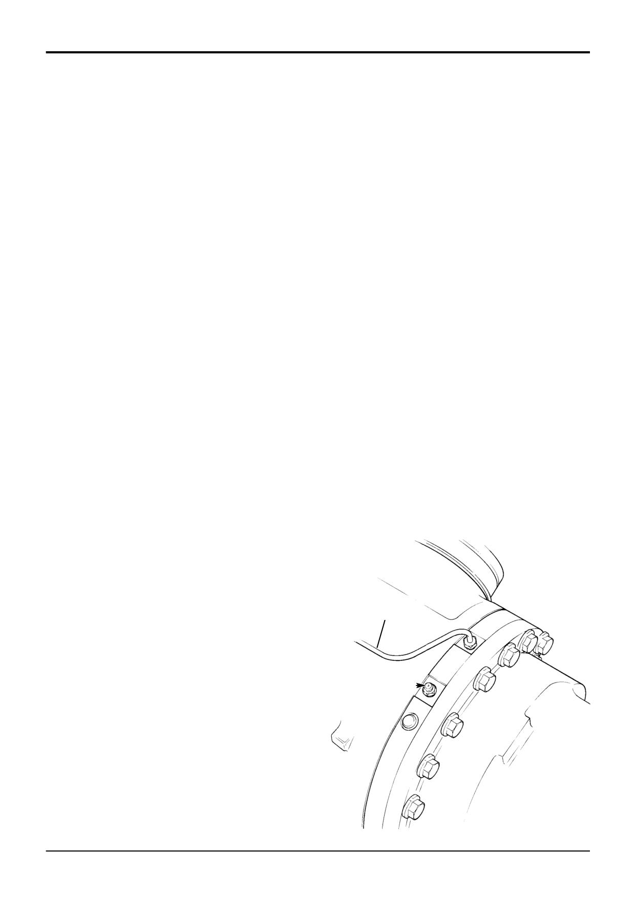
a Attach a tube to the right hand brake bleed screw
A, ensuring that the free end of the tube is
immersed in fluid contained in a suitable container.
b Open the brake bleed screw and apply full pedal
strokes of the right hand brake pedal until all air is
expelled.
c Close the brake bleed screw with the pedal fully
depressed.
4
Left Hand Master Cylinder
a Repeat procedure as for 'Right Hand Master
Cylinder' but use left hand bleed screw and pedal.
5
Bridge Pipe
a Attach a tube to either the left or right hand brake
bleed screw, ensuring that the free end of the tube
is immersed in fluid contained in a suitable
5
container.
b Make sure that the brake pedals are locked
together.
Note: 4WS machines do not have dual pedal braking. These
machines are fitted with a single pedal that operates both
A
master cylinders.
c Open the bleed screw and apply full pedal strokes
of the brake pedals until all air is expelled.
d Close the bleed screw with the pedals fully
depressed.
6
Repeat the procedures as necessary.
7
Top up the reservoir to the full mark.
S107710-1
9803/3280
Issue 1
Section G
Brakes
Section G
50 - 1
Parking Brake
50 - 1
Torque Figures
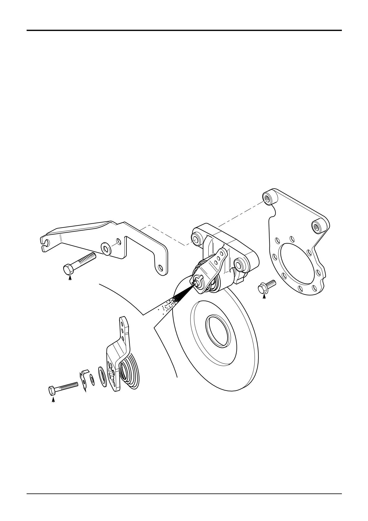
The illustration shows a typical installation.
Where appropriate, the grade of bolt is indicated in
parenthesis eg. (10.9). Refer also to relevant dismantling and
assembly procedures.
Torque Settings
Item
Nm
lbf ft
A
166
122
(12.9)
B
13-15
9-12
C
255
188
(10.9 Tuflok)
C
A
A396540
B
9803/3280
Issue 1
Section G
Brakes
Section G
50 - 2
Parking Brake
50 - 2
Calliper Removal and Replacement
Replacement
! WARNING
This is a safety critical installation. Do not attempt to do
Replacement is the reverse of the removal sequence.
this procedure unless you are skilled and competent to
do so.
1
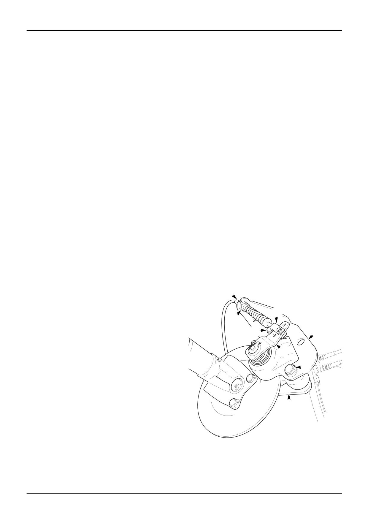
Locate the calliper on the brake disc and fit new
mounting bolts C with hardened washers, torque
Installation and mounting of the parking brake calliper
tighten to 255 Nm (188 lbf ft).
requires tightening of the mounting bolts to a specific
torque figure. Do not attempt to do this job unless you
2
Insert cable into bracket D, do not tighten locknuts B at
have the correct tools available.
this stage as the brake will need adjusting.
0010
! WARNING
*
3
Refit the clevis A into the hole in the operating lever E
Before working on the parking brake, park on level
as shown.
ground and put chocks each side of all four wheels. Stop
the engine and disconnect the battery so that the engine
4
Make sure there is adequate freedom of movement of
cannot be started. If you do not take these precautions
operating lever E to ensure a positive brake application,
the machine could run over you.
and that the lever returns to the rest position when the
BRAK 8-8
parking brake is released.
! WARNING
Brake pads generate dust which if inhaled, may
5
Adjust the parking brake, see Service Procedures,
endanger health. Wash off the calliper before
Parking Brake Adjustment. Never unscrew the
commencing work. Clean hands thoroughly after work.
clevis A to adjust the cable.
13-3-1-3
Removal
Torque Settings
1
Release the parking brake lever (lever horizontal).
Item
Nm
lbf ft
2
Disconnect clevis A, note which of the three holes on
C
255
188
the lever is used.
3
Undo locknuts B and disconnect the cable from the
bracket D.
B
4
Support the calliper and remove the two mounting bolts
and hardened washers C. Lift the calliper and bracket D
clear of the brake disc.
A
B
Note: Do not remove axle mounting bracket F unless it
needs to be renewed.
C
D
E
C
F
A396181
9803/3280
Issue 2*
Section G
Brakes
Section G
50 - 3
Parking Brake
50 - 3
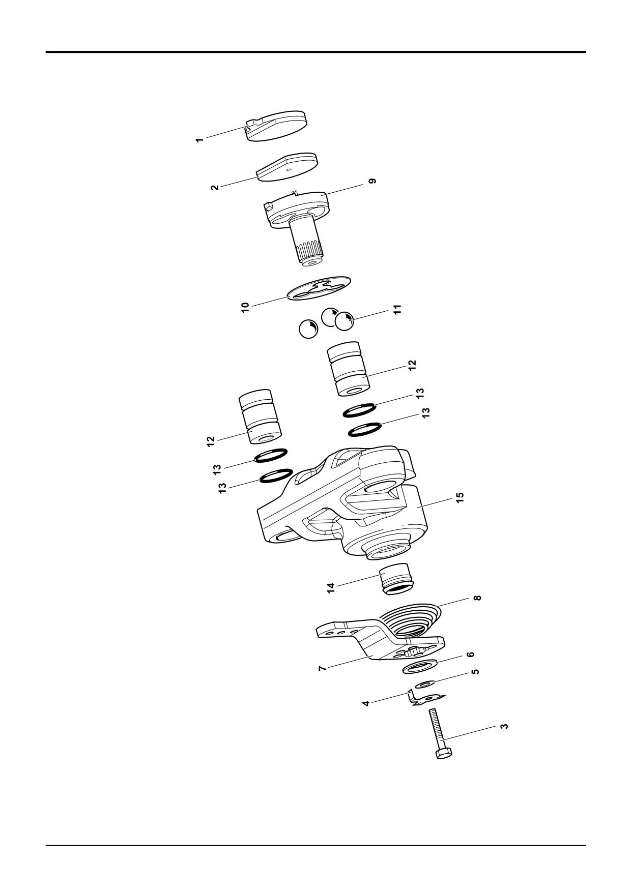
Component Listing:
1
Carrier Side Pad
2
Lever Side Pad
3
Bolt
4
Anti-rotation Clip
5
Washer
6
Washer
7
Lever
8
Spring
9
Rotor
10
Ball Spacer
11
Ball Bearings
12
Mounting Bush
13
O-ring
14
Shaft Seal
15
Housing
228362
9803/3280
Issue 1
Section G
Brakes
Section G
50 - 4
Parking Brake
50 - 4
Calliper Dismantling and Assembly
Dismantling
Inspection
The numerical sequence shown on the illustration on the
1
Clean and dry all parts. Check all parts are free from
adjacent page is intended as a guide to dismantling.
excessive wear, damage or corrosion. Light scores or
stains should be removed. Renew corroded or deeply
! WARNING
scored parts.
This is a safety critical installation. Do not attempt to do
2
Check rotor 9 for damage or distortion. Renew if
this procedure unless you are skilled and competent to
necessary.
do so.
Always renew both brake pads if the parking brake has
Installation and mounting of the parking brake calliper
been used in an emergency.
requires tightening of the mounting bolts to a specific
torque figure. Do not attempt to do this job unless you
3
Check the ball pockets in housing 15 for signs of
have the correct tools available.
scoring, pitting, damage or corrosion. Renew the
0010
housing if damaged.
! WARNING
4
Check spring 8 is not broken or distorted.
Before working on the parking brake, park on level
ground and put chocks each side of all four wheels. Stop
5
Check the condition of the disc surface. Renew the disc
the engine and disconnect the battery so that the engine
if badly warped, pitted or worn.
cannot be started. If you do not take these precautions
the machine could run over you.
BRAK 8-8
! WARNING
Brake pads generate dust which if inhaled, may
endanger health. Wash off the calliper before
commencing work. Clean hands thoroughly after work.
13-3-1-3
1
Remove the calliper and brake pads, refer to Calliper -
Removal and Replacement.
2
Bend the tabs on anti-rotation clip 4. Remove bolt 3,
anti-rotation clip 4 and washers 5 and 6. Hold lever 7
against the tension of the spring as the bolt is removed.
3
Note the position of lever 7 and the splines of the shaft.
Mark the end of the shaft and lever 7 to aid assembly.
Remove lever 7 and spring 8.
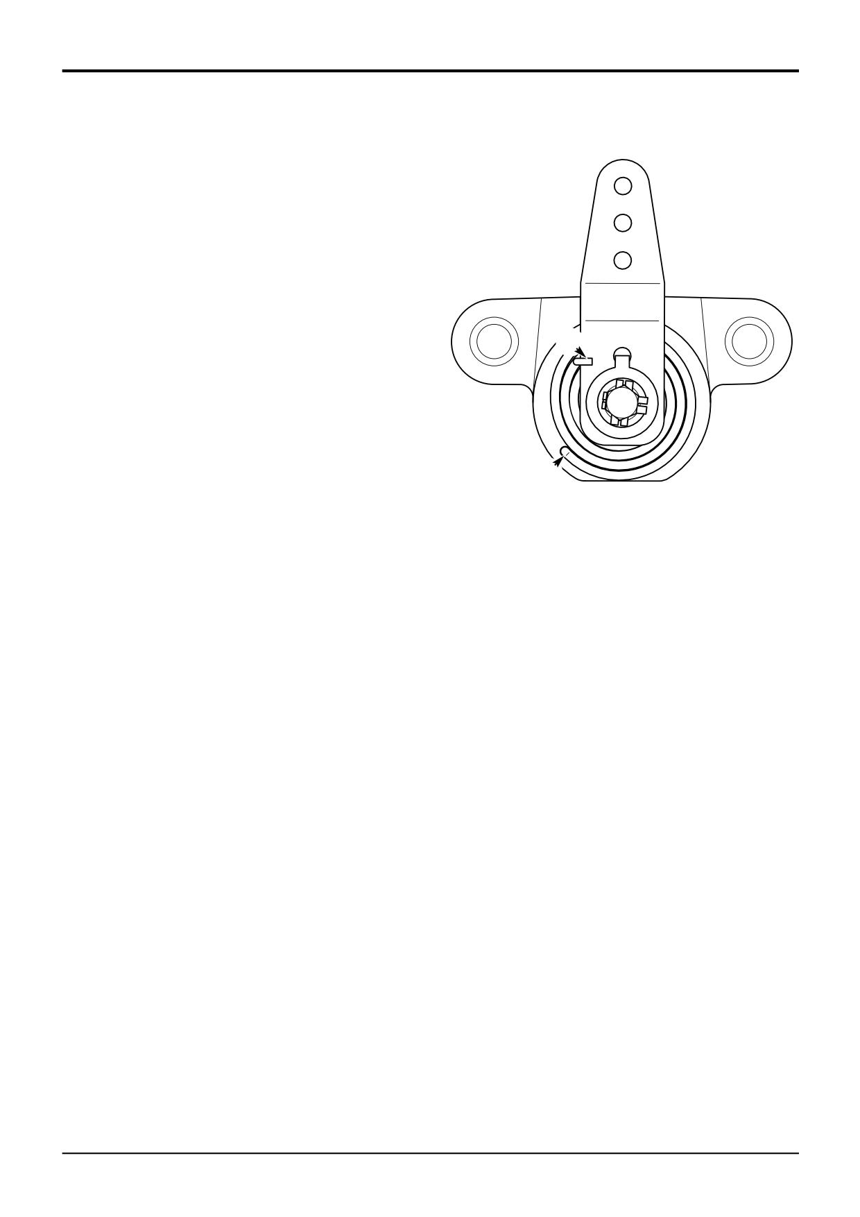
4
Push out rotor 9 and remove ball spacer 10 and ball
bearings 11. Take care not to lose the ball bearings.
5
Push out mounting bushes 12 and remove O-rings 13.
Note: Shaft seal 14 will not need to be renewed unless
excessively worn or damaged. If removal is necessary, press
the seal out from inside the housing using a suitable spacer
block and bench press. Clean out any remains of the seal
after removal.
9803/3280
Issue 1
1
12
13
2
13
10
7
14
4
9
11
12
13
13
15
6
5
8
3
Section G
Brakes
Section G
50 - 6
Parking Brake
50 - 6
Dismantling and Assembly (cont’d)
Assembly
Before assembly make sure all parts are clean and
serviceable.
1
Fit a new shaft seal 14 if removed. Install the seal as
shown. Press the seal into the housing using a suitable
spacer block and bench press.
2
Coat the the shaft and ball pockets of rotor 9 and the
ball pockets of housing 15 with silicone grease.
Y
3
Insert the three ball bearings 11 into the pockets in the
housing 15. Insert ball spacer 10.
4
Slide rotor 9 through the casting and seat the ball
pockets against the bearings.
5
Position spring 8 over the shaft of rotor 9. Insert the
A348331
large diameter end of the spring into hole X in the face
X
of the housing.
6
Locate the small diameter end of spring 8 around the
outside edge of lever 7 as shown at Y.
7
Fit lever 7. Align the lever to the mark made during
dismantling.
8
Hold the lever against the tension of the spring and fit
washers 6 and 5, and new anti-rotation clip 4. Fit bolt 3
and tighten to 13-16 Nm (9-12 lbf ft).
9
Bend up a tab of the anti-rotation clip that aligns with
one of the flats on the bolt.
10
Fit the new brake pads, refer to Service Procedures -
Parking Brake - Renewing the Brake Pads.
11
Lubricate the O-rings 13 and bushes 12 with silicone
grease. Fit O-rings into the housing and insert mounting
bushes. Wipe off any excess grease.
12
Before fitting the calliper, ensure the lever rotates
smoothly and that the lever side pad 2 returns to the off
position when the lever is released.
13
Refit the brake calliper. Refer to Calliper - Removal
and Replacement.
14
Adjust the parking brake, refer to Service Procedures
- Parking Brake - Adjustment.
Torque Settings
Item
Nm
lbf ft
3
13-16
9-12
9803/3280
Issue 1
Section G
Brakes
Section G
50 - 7
Parking Brake
50 - 7
Brake Disc - Removal and Replacement
! WARNING
This is a safety critical installation. Do not attempt to do
this procedure unless you are skilled and competent to
do so.
! WARNING
Before working on the parking brake, park on level
ground and put chocks each side of all four wheels. Stop
the engine and disconnect the battery so that the engine
cannot be started. If you do not take these precautions
the machine could run over you.
BRAK 8-8
Removal
1
Disconnect the propshaft to the rear axle, refer to
Section F Propshafts - Removal and Replacement.
2
Remove the calliper from the axle mounting bracket F,
refer to Calliper Removal and Replacement.
3
Undo the stake nut and withdraw the brake disc from
the drive pinion shaft.
Note: If the axle is not mounted to a machine, fit flange
spanner (service tool 992/04800) to prevent brake disc and
drive pinion shaft turning when loosening or tightening the
stake nut. Refer to Section F - Service Tools.
Replacement
Replacement is the reverse of the removal sequence.
1
Fit a new stake nut and torque tighten to 300 Nm (221
lbf ft), see Note:
2
Re-stake the nut using a square ended staking tool.
Torque Settings
Item
Nm
kgf m
lbf ft
1
300
30.6
221
9803/3280
Issue 1
Section H
Steering
Section H
i
i
Contents
Page No.
Service Tools
1 - 1
Technical Data
System Type
2 - 1
Basic System Operation
2 Wheel Steer Machines
- Steer System Schematics
3 - 1
- Hydraulic Operation
3 - 2
4 Wheel Steer Machines
- Steer System Schematics
3 - 3
- Hydraulic Operation
3 - 4
- Electrical Operation
3 - 5
Circuit Descriptions
Steer Unit Operation
- 2 Wheel Steer Machines
4 - 1
- 4 Wheel Steer Machines
4 Wheel Steer Mode
4 - 2
2 Wheel Steer Mode
4 - 13
Crab Steer Mode
4 - 14
Priority Valve Operation
5 - 1
Fault Finding
10 - 1
Service Procedures
Steering System
- Bleeding
20 - 1
- Pressure Testing
20 - 2
Proximity Switch - Setting
20 - 3
Steer Mode Valve - Checking Solenoid Operation
20 - 4
Priority Valve
- Cleaning
20 - 5
- Standby Pressure Testing
20 - 6
Power Track Rod
Removal and Replacement
30 - 1
Link Arms - Removal and Replacement
31 - 1
Rams - Dismantling and Assembly
32 - 1
Priority Valve
Removal and Replacement
40 - 1
Dismantling and Assembly
40 - 1
Bleeding
40 - 1
Steer Mode Valve
Removal and Replacement
45 - 1
Dismantling and Assembly
45 - 2
Hydraulic Steer Unit
Removal and Replacement
50 - 1
Dismantling and Assembly
50 - 3
9803/3280
Issue 1
Section H
Steering
Section H
1 - 1
Service Tools
1 - 1
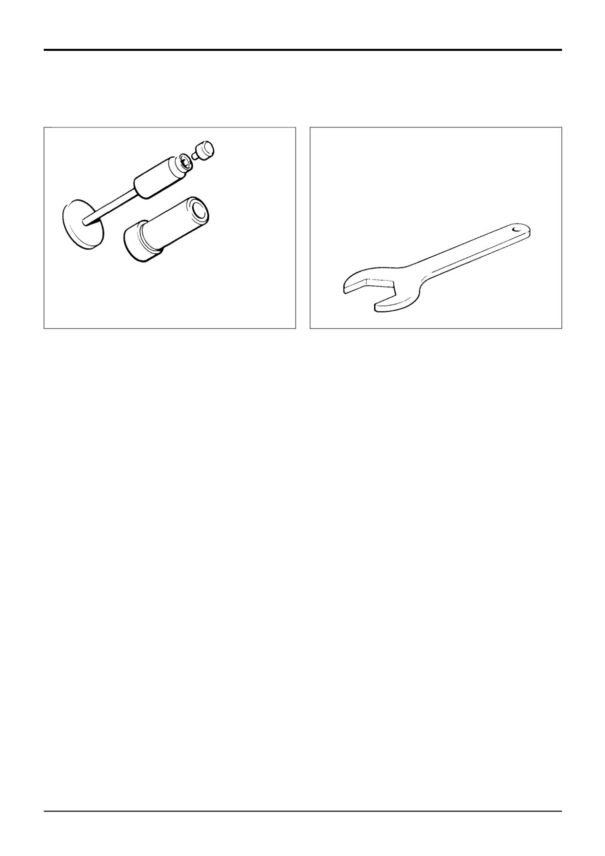
Hexagon Spanners for Ram Pistons and End Caps
992/09300
55mm A/F
992/09400
65mm A/F
992/09500
75mm A/F
992/09600
85mm A/F
992/09700
95mm A/F
992/09900
115mm A/F
992/10000
125mm A/F
S191750
892/0018
Seal Fitting Tool for fitting 'O' ring and kin
ring to Hydraulic Steer Unit
S193930
9803/3280
Issue 1
Section H
Steering
Section H
2 - 1
Technical Data
2 - 1
System Type
Full power hydrostatic with selectable 2-wheel, 4-
wheel and crab steer modes on 4 wheel steer
machines.
Oil supply from Main Hydraulic Pump via Priority Valve
to Steer Unit Valve complete with Load Sensing and
Integral Relief Valve.
Double acting power track rod rams mounted on axles.
2 Wheel Steer Machines
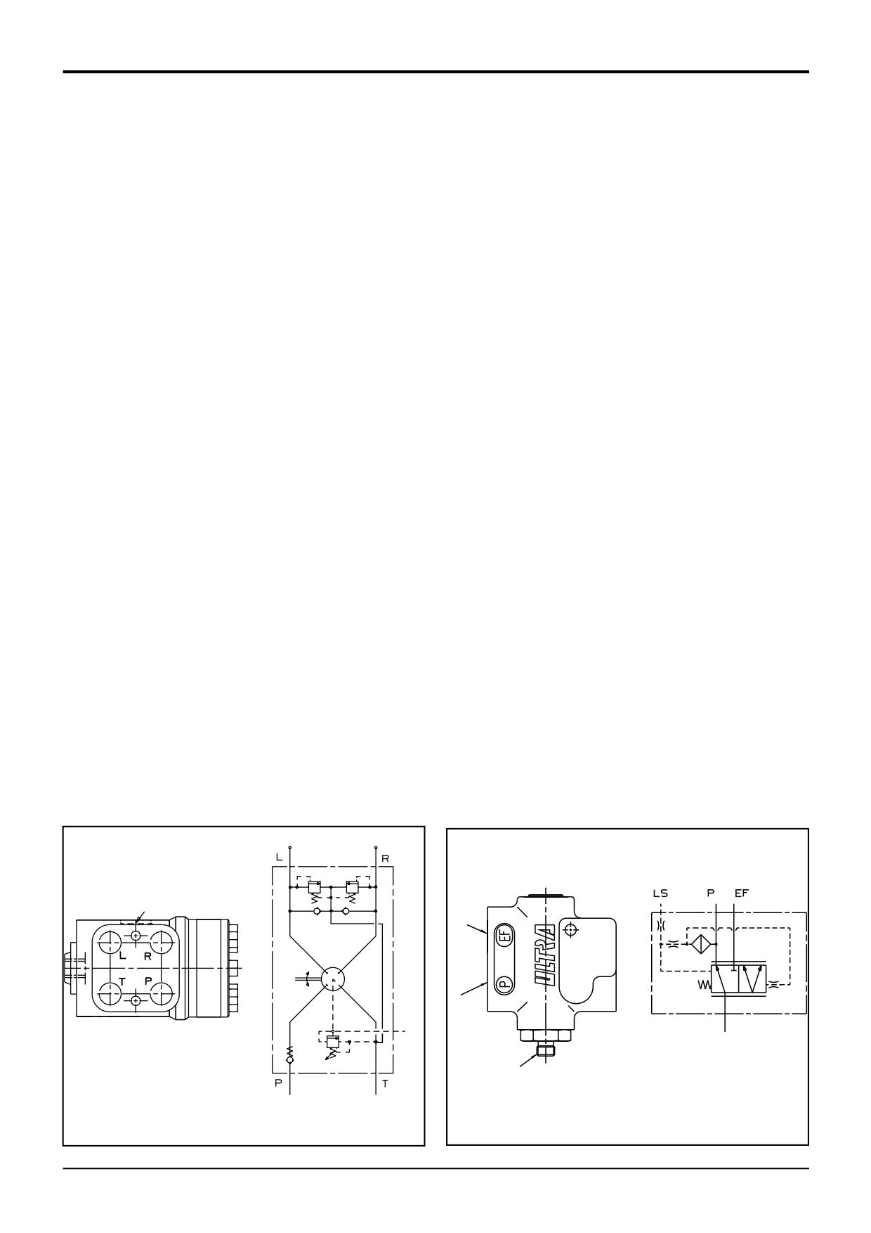
STEER UNIT - FIG 1
Model
200 OSPC
- Volumetric Displacement
200 cc/rev
- Relief Valve
Fitted
- Check Valve
Fitted
- Shock Valve
Fitted
- Relief Valve Operating Pressure (at 1500 revs/min)
120 ± 3 bar
122 ± 3.5 kgf/cm2
1740 ± 50 lbf/in2
-Shock Valve Operating Pressure
175 - 190bar 178 - 199 kgf/cm2
2538 - 2756 lbf/in2
Model
250 OSPC
- Volumetric Displacement
250 cc/rev
- Relief Valve
Fitted
- Check Valve
Fitted
- Shock Valve
Not Fitted
- Relief Valve Operating Pressure (at 1500 revs/min)
120 ± 3 bar
122 ± 3.5 kgf/cm2
1740 ± 50 lbf/in2
PRIORITY VALVE - FIG 2
-Stand by Pressure
7 bar
7.1 kgf/cm2
102 lbf/in2
4 Wheel Steer Machines
STEER UNIT - FIG 1
Model
160 OSPC
- Volumetric Displacement
160 cc/rev
- Relief Valve
Fitted
- Check Valve
Fitted
- Shock Valve
Fitted
- Relief Valve Operating Pressure (at 1500 revs/min)
120 ± 3 bar
122 ± 3.5 kgf/cm2
1740 ± 50 lbf/in2
- Shock Valve Operating Pressure
175 - 190bar 178 - 199 kgf/cm2
2538 - 2756 lbf/in2
PRIORITY VALVE - FIG 2
-Stand by Pressure
7 bar
7.1 kgf/cm2
102 lbf/in2
LS
EF
P
LS
LS
A263810
A263820
FIG 1
FIG 2
9803/3280
Issue 1
Section H
Steering
Section H
3 - 1
Basic System Operation
3 - 1
2 Wheel Steer Machines
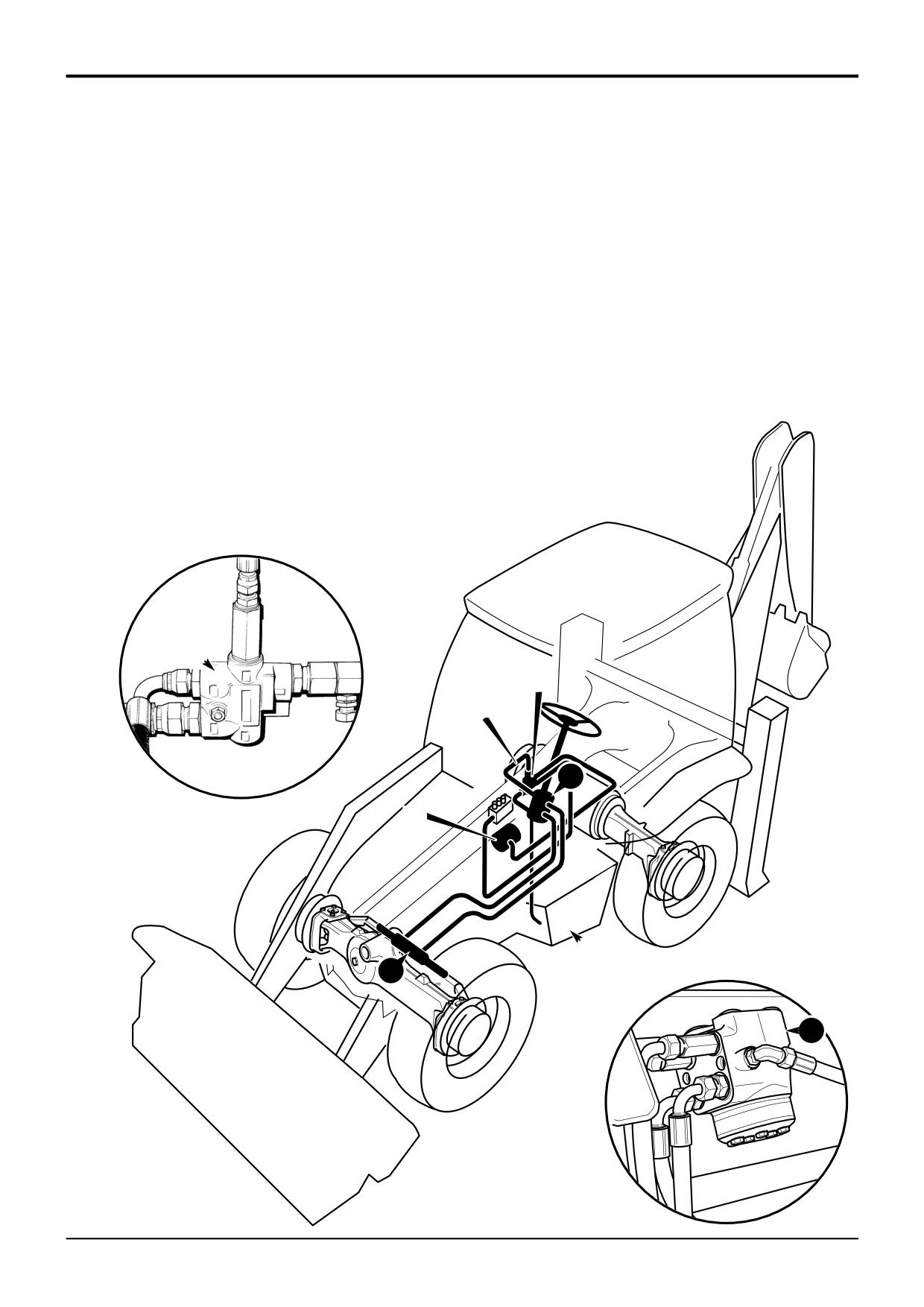
Steer System Schematics
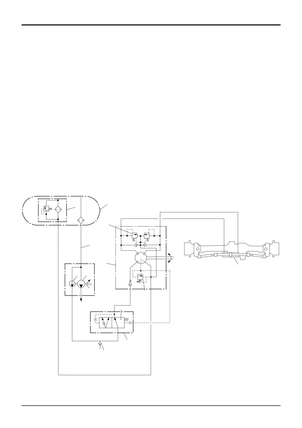
Component Key:
P1
Pump, Main Section
P2
Pump, Secondary Section
P2A
Pressure Test Point
S
Suction Line
T
Tank
6
In-tank Filter
7
Priority Valve
10
Front Power Track Rod Ram
42
Steer Unit
43
Shock Valve
44
Steer Unit Relief Valve
Note: Hydraulic component port identification letters are
shown in parenthesis, e.g. (LS). The same letters will be
stamped on the actual component.
T
6
43
(L)
(R)
S
42
(LS)
10
P2
P1
(P)
(T)
44
(CF)
(EF)
(LS)
(P)
7
P2A
A263860
9803/3280
Issue 1
Section H
Steering
Section H
3 - 2
Basic System Operation
3 - 2
2 Wheel Steer Machines
Hydraulic Operation
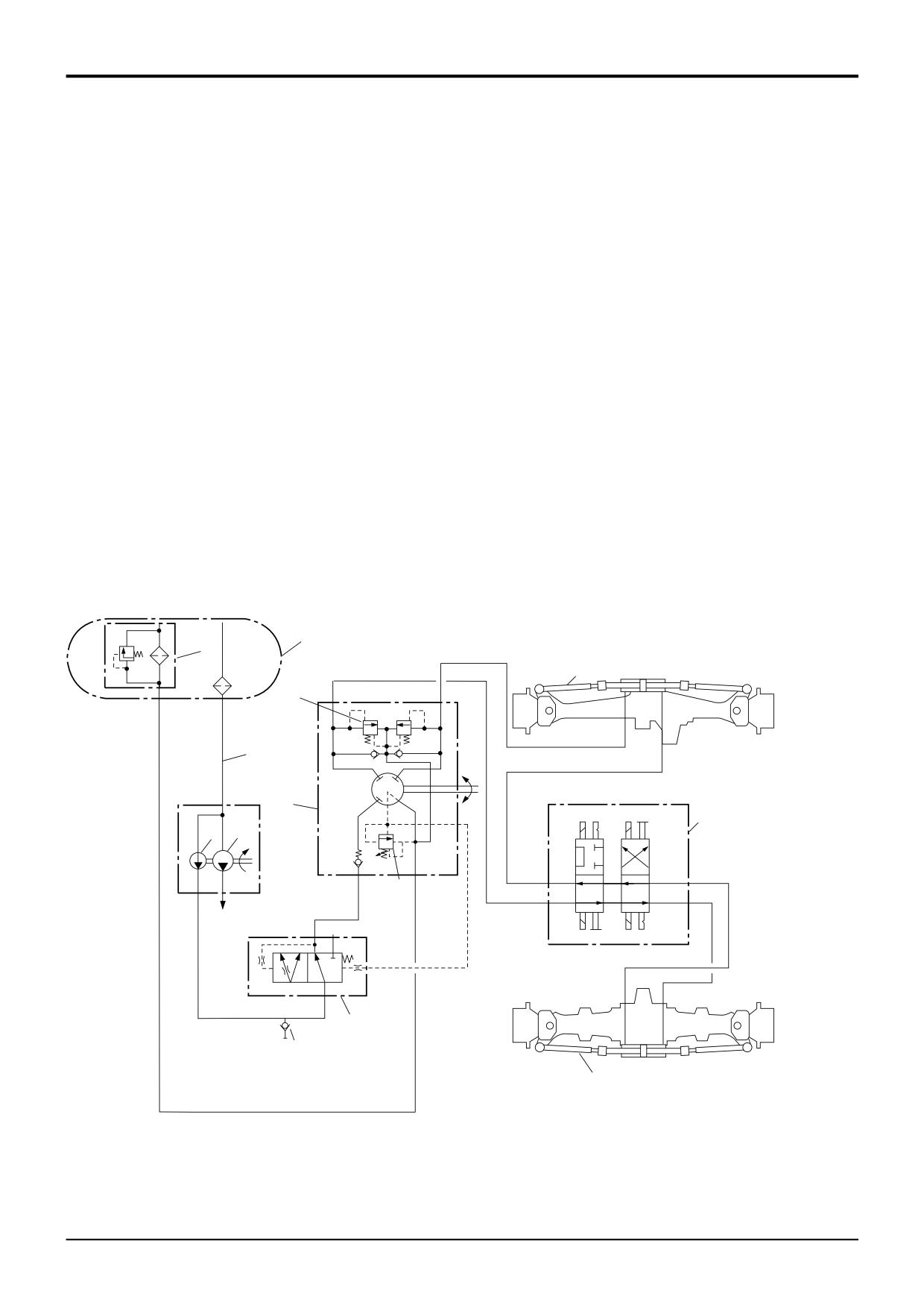
The main components of the steering system are the priority
valve 7, load sensing steer unit 42, hydraulic tank T and the
front power track rod ram 10.
When the steering wheel is turned, a pressure demand is
sensed at the priority valve 7 via load sensing line LS.
Oil from the hydraulic pump P2 is then distributed via the
priority valve to the steer unit 42, which then directs the oil
to the front power track rod ram 10 untill the required
steering lock is achieved.
When the steering lock is held, the pressure signal LS
ceases, flow from the hydraulic pump P2 is now distributed
to the main hydraulic circuit via the priority valve 7.
Maximum steering system pressure is controlled by a relief
valve located in the steering unit 42.
7
7
LS
42
P2
T
10
42
A401110
9803/3280
Issue 1
Section H
Steering
Section H
3 - 3
Basic System Operation
3 - 3
4 Wheel Steer Machines
Steer System Schematics
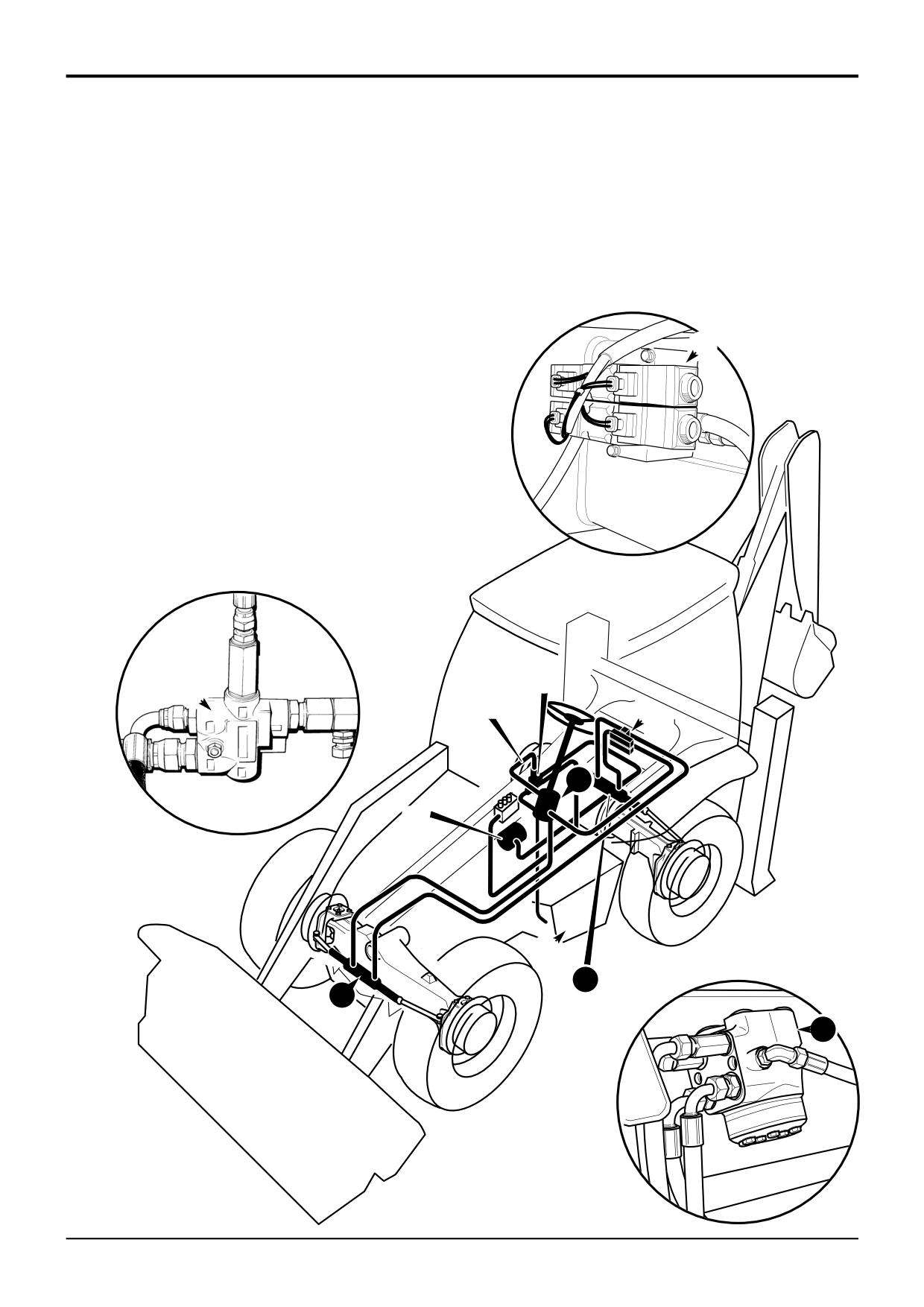
Component Key:
P1
Pump, Main Section
P2
Pump, Secondary Section
P2A
Pressure Test Point
S
Suction Line
T
Tank
6
In-tank Filter
7
Priority Valve
8
Steer Mode Control Valve
10
Front Power Track Rod Ram
11
Rear Power Track Rod Ram
42
Steer Unit
43
Shock Valve
44
Steer Unit Relief Valve
Note: Hydraulic component port identification letters are
shown in parenthesis, e.g. (LS). The same letters will be
stamped on the actual component.
T
6
10
43
(L)
(R)
S
42
(LS)
8
P2
P1
(T)
(B)
(P)
44
(T)
(P)
(A)
(CF)
(EF)
(LS)
(P)
7
P2A
11
A263850
9803/3280
Issue 1
Section H
Steering
Section H
3 - 4
Basic System Operation
3 - 4
4 Wheel Steer Machines
Hydraulic Operation
The main components of the steering system are the priority
valve 7, load sensing steer unit 42, hydraulic tank T, front
power track rod ram 10 and rear power track rod ram 11.
When the steering wheel is turned, a pressure demand is
sensed at the priority valve 7 via load sensing line LS.
Oil from the hydraulic pump P2 is then distributed via the
priority valve to the steer unit 42.
8
When left turn is selected, oil is distributed from steer unit 42
to the rear power track rod ram 11 via the steer mode
control valve 8. When right turn is selected, oil is delivered
directly to the front power track rod ram 10.
When the steering lock is held, the pressure signal LS
ceases, flow from the hydraulic pump is now distributed to
the main hydraulic circuit via the priority valve 7.
A396570
Maximum steering system pressure is controlled by a relief
valve located in the steering unit 42.
7
7
LS
8
42
P2
T
11
10
42
A401120
9803/3280
Issue 1
Section H
Steering
Section H
3 - 5
Basic System Operation
3 - 5
4 Wheel Steer Machines
B
Electrical Operation
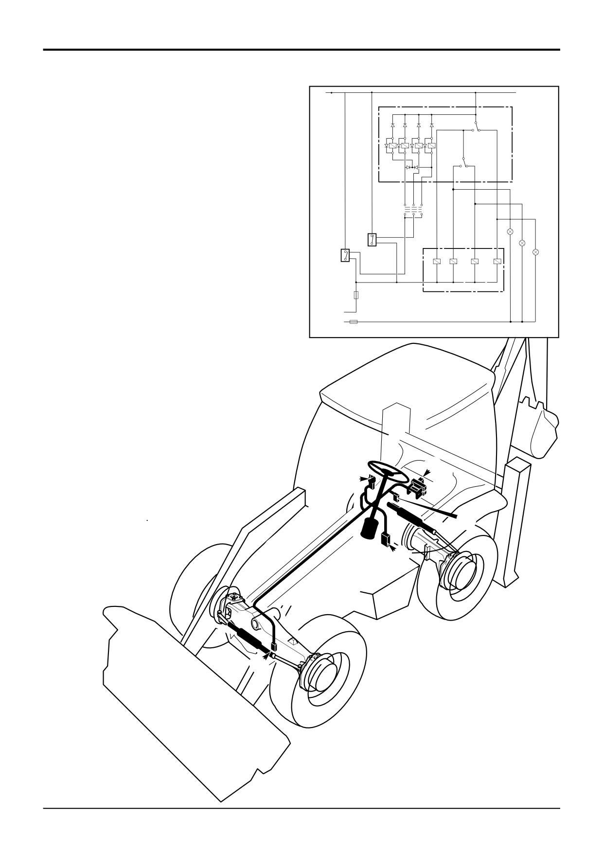
Three steering modes are available:
- 2 Wheel Steer (front axle)
- 4 Wheel Steer
- Crab Steer
The three modes are selected in the cab from a three
position switch A which operates relays in the steer mode
A
control unit B. The relays switch the energising supplies to
the solenoid operated steer mode control valve C. Proximity
E
L1
switches on the front D and rear E axles signal when the
L2
wheels are in the straight ahead position.
C
L3
D
Lights L1, L2 or L3 on the instrument panel illuminate to
indicate the steer mode currently operative.
In 2 wheel steer mode only the front wheels are steered. In 4
wheel steer mode both axles are steered, giving a smaller
A401140
turning circle and so improving manoeuvrability. The crab
steer mode allows the machine to be driven diagonally into
loading/unloading positions which might otherwise be
inaccessible.
The system is prevented from changing mode until the
relevant proximity switch is energised. If, for example, the
system is set in 4 wheel steer and 2 wheel steer is then
selected, the system will stay in 4 wheel steer untill the rear
wheels are turned to the straight ahead position, thus
energising the rear axle proximity switch. The rear wheels
are then hydraulically locked in the straight ahead position.
C
A
E
B
D
A401130
9803/3280
Issue 1
Steer Unit Operation
- 2 Wheel Steer Machines
On 2 wheel steer machines the hydraulic steer unit
operation is identical to that described for the 4
wheel steer machines, except the unit pumps oil
out directly to a power track rod ram fitted on the
front axle only. Also, therefore the 2 wheel steer
machines do not have a steer mode control valve.
Refer to, Steer Unit Operation - 4 Wheel Steer
Machines.
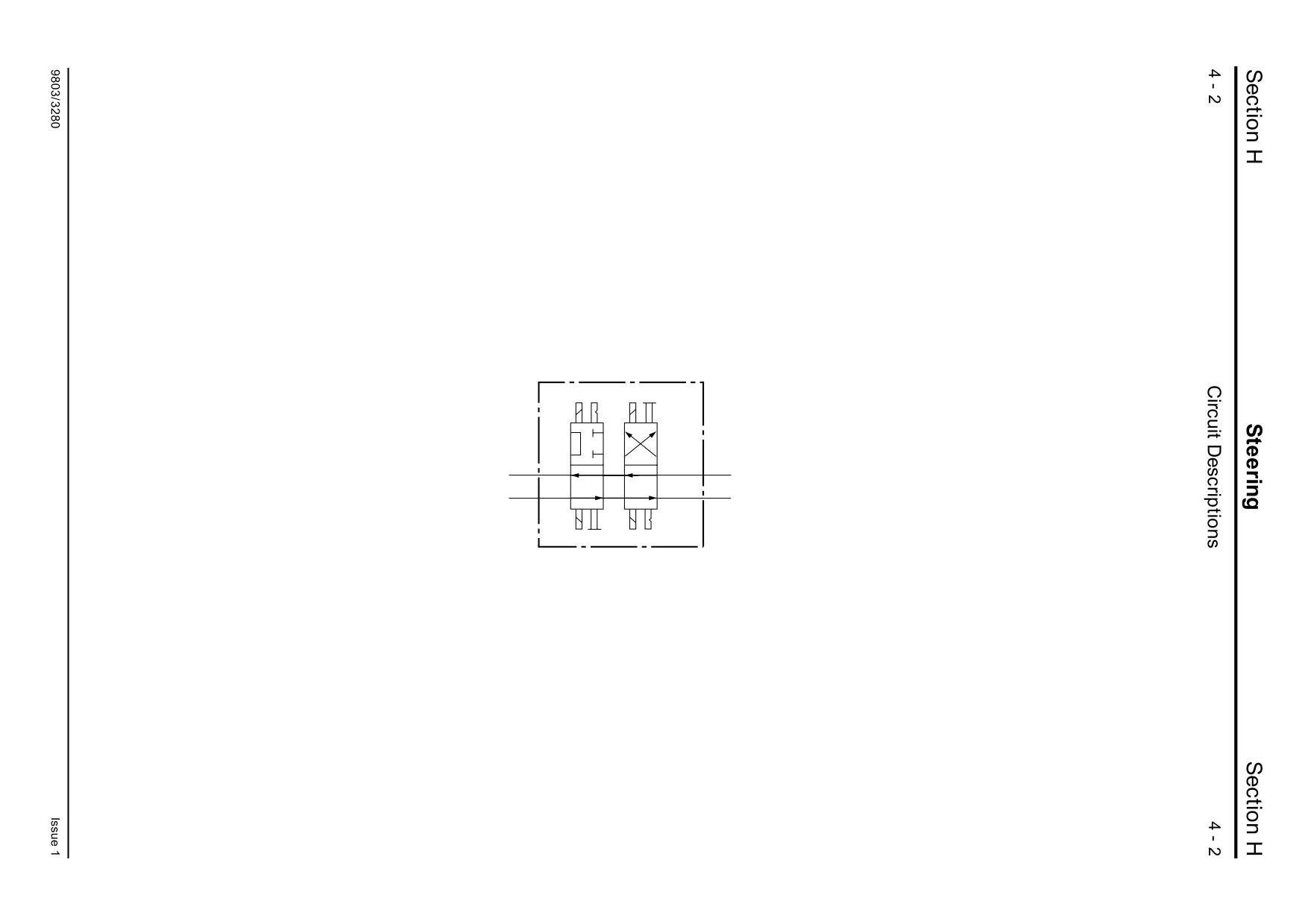
Steer Unit Operation
- 4 Wheel Steer Machines
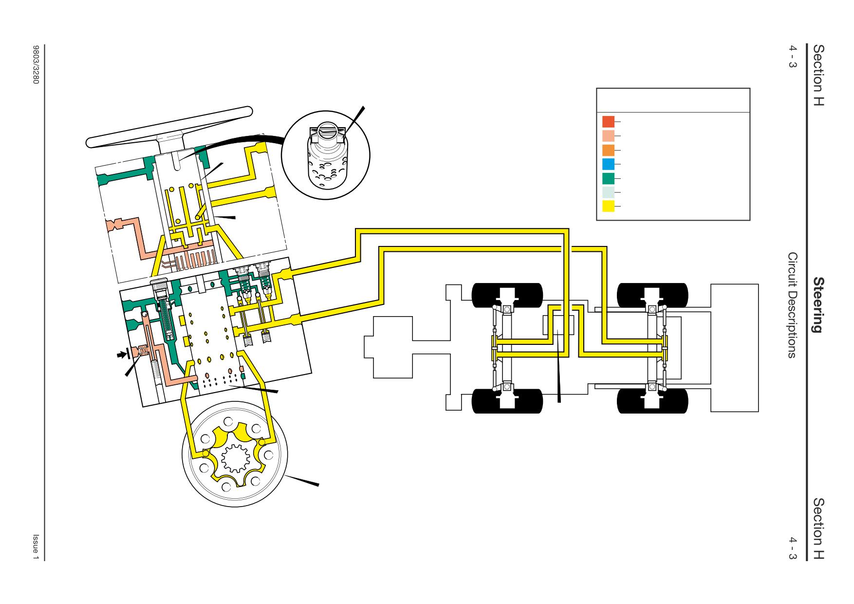
4 Wheel Steer Mode
- Neutral
Flow from the priority valve enters the steering unit
through the bottom right hand port past the non-
return valve 43C. When the steering wheel is
stationary the inner spool A and sleeve B are held
in the neutral position by the centring springs K. As
the unit is 'closed centre' the flow from the pump is
dead ended by the steering unit.
In 4 wheel steer mode the spools of the steer mode
control valve X are configured as shown.
Component Key:
A Inner Spool
B Sleeve
D Stator
K Centring Springs
X Steer Mode Control Valve
43C Non-Return Valve
A395730
K
Key to Oil Flow & Pressure
Full Pressure
Pressure
Servo
A
Neutral
Exhaust
Cavitation
Lock Up
B
A390630
43C
B
X
D
A395640
Key to Oil Flow & Pressure
Full Pressure
Pressure
Servo
Neutral
A
Exhaust
Cavitation
Lock Up
B
A390630
40
43B
41
LS
B
X
D
A395650
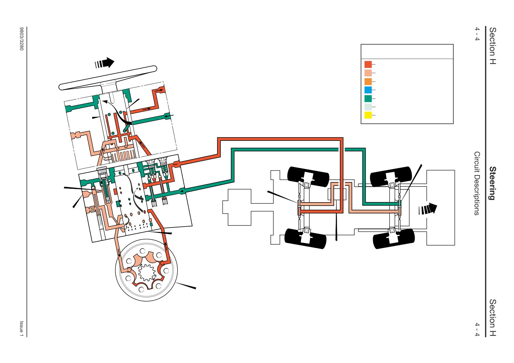
Steer Unit Operation
- 4 Wheel Steer Machines
4 Wheel Steer Mode
- Left Turn
The illustration shows the flow through the steering
unit in a left hand turn condition. Turning the
steering wheel rotates the inner spool A a few
degrees relative to the outer spool B, and sends a
pressure signal to the relief valve 43B and through
the LS port back to the priority valve.
The relative movement between A and B directs
pressure oil through 6 of the 12 holes in the bottom
of sleeve B. The metering unit is linked to the
spools by a cross pin. As the steering is operated
the oil is diverted by inner spool A into the stator D.
The rotor lobes pump the oil out to one side of the
rear power track rod ram 41 turning the rear wheels
to the right. At the same time pressurised oil from
the other side of the power track rod ram 41 is fed
to the front power track rod ram 40, hence turning
the front wheels the required degree of left turn.
Component Key:
A Inner Spool
B Outer Spool
D Stator
LS Load Sensing Port
X Steer Mode Control Valve
40
Front Power Track Rod Ram
41
Rear Power Track Rod Ram
43B Relief Valve
Steer Unit Operation
- 4 Wheel Steer Machines
4 Wheel Steer Mode
- Right Turn
The illustration shows the flow through the steering
unit in a right hand turn condition. The operation is
identical to that described for a left hand turn,
except that the oil is diverted by spool A to the
other side of stator D and power track rod rams 40
and 41.
Component Key:
A Inner Spool
B Outer Spool
D Stator
LS Load Sensing Port
X Steer Mode Control Valve
40
Front Power Track Rod Ram
41
Rear Power Track Rod Ram
43B Relief Valve
43C Non-Return Valve