JCB 3CX, 4CX, 214e, 214, 215, 217 & VARIANTS Backhoe Loader. Service Manual - page 30
Section F
Transmission
Section F
120 - 3
Powershift Gearbox
120 - 3
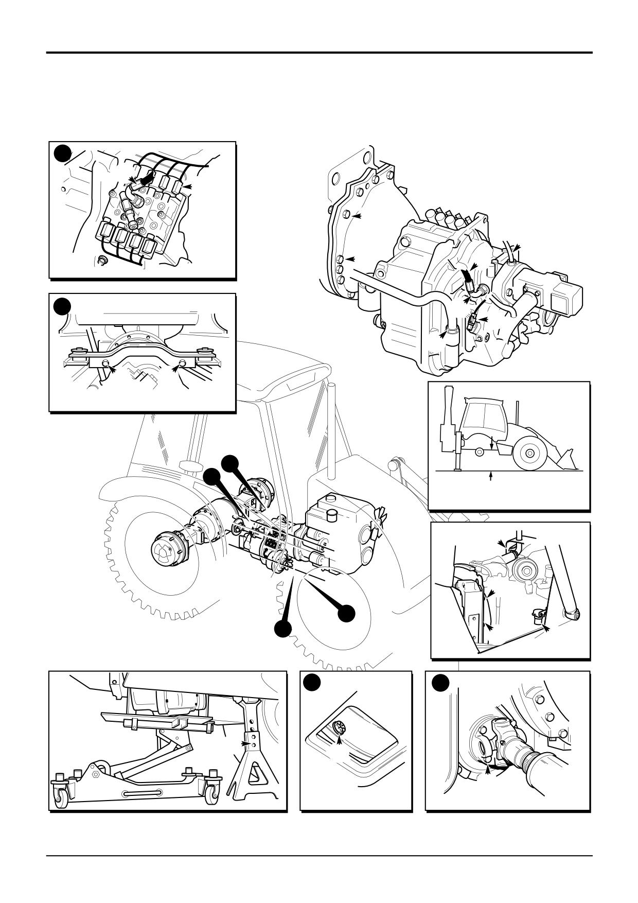
Removal and Replacement (cont’d)
c
R
M
J
K
T
N
d
P
S
L
H
H
d
c
X
F
G
b
a
G
E
a
b
Z
Y
D
B
A401320
9803/3280
Issue 1
Section F
Transmission
Section F
120 - 4
Powershift Gearbox
120 - 4
Removal and Replacement (cont’d)
Replacement
Replacement is a reversal of the removal procedure but note
the following:
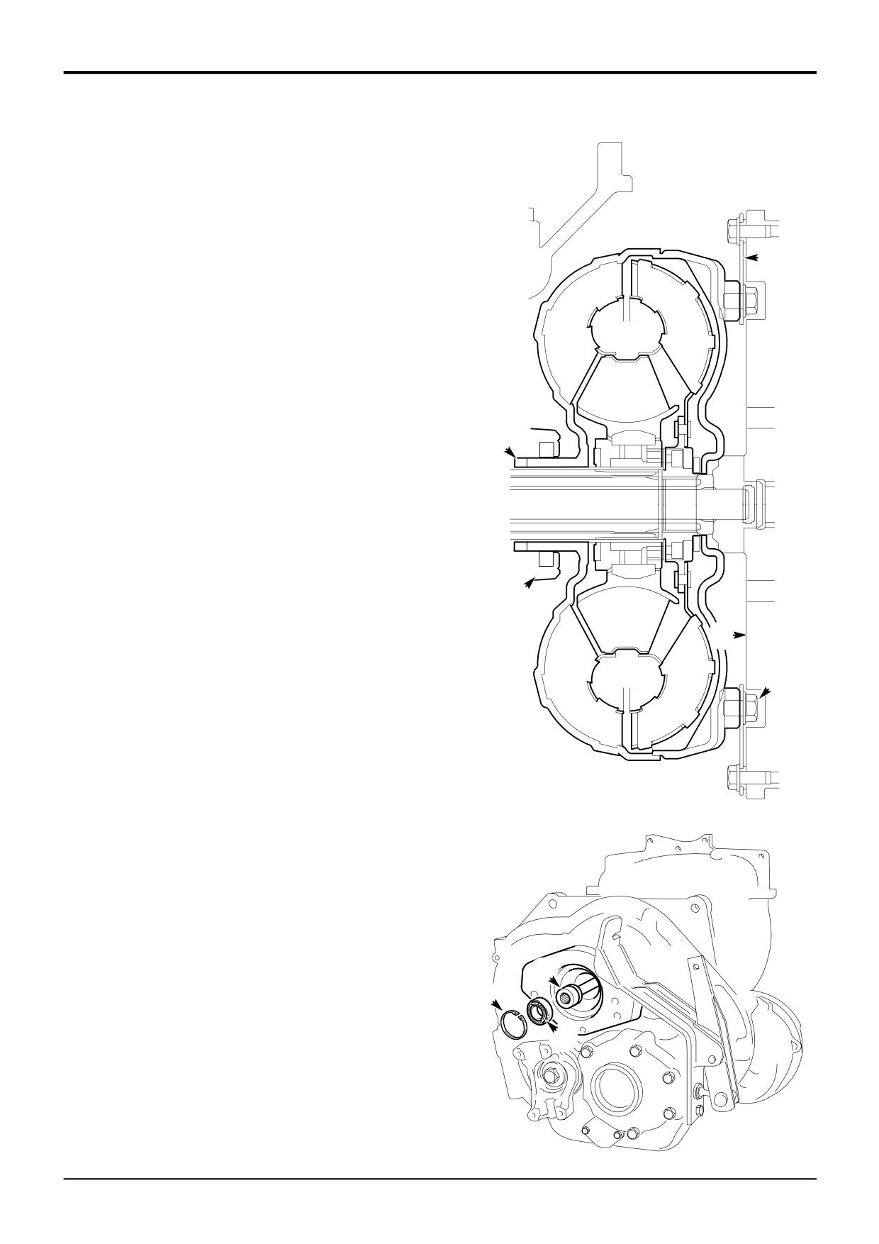
1
Before replacing the gearbox remove circlip 5 and
8
withdraw the pump driveshaft 6 together with its
bearing 7 approximately 50 mm (2.0 in). The shaft can
then be engaged after the gearbox has been fitted,
making replacing the gearbox easier. Remember to
engage the pump drive shaft, refit the bearing and
circlip after the gearbox has been fitted.
2
Set the torque converter as described in Torque
Converter, Removal and Replacement.
3
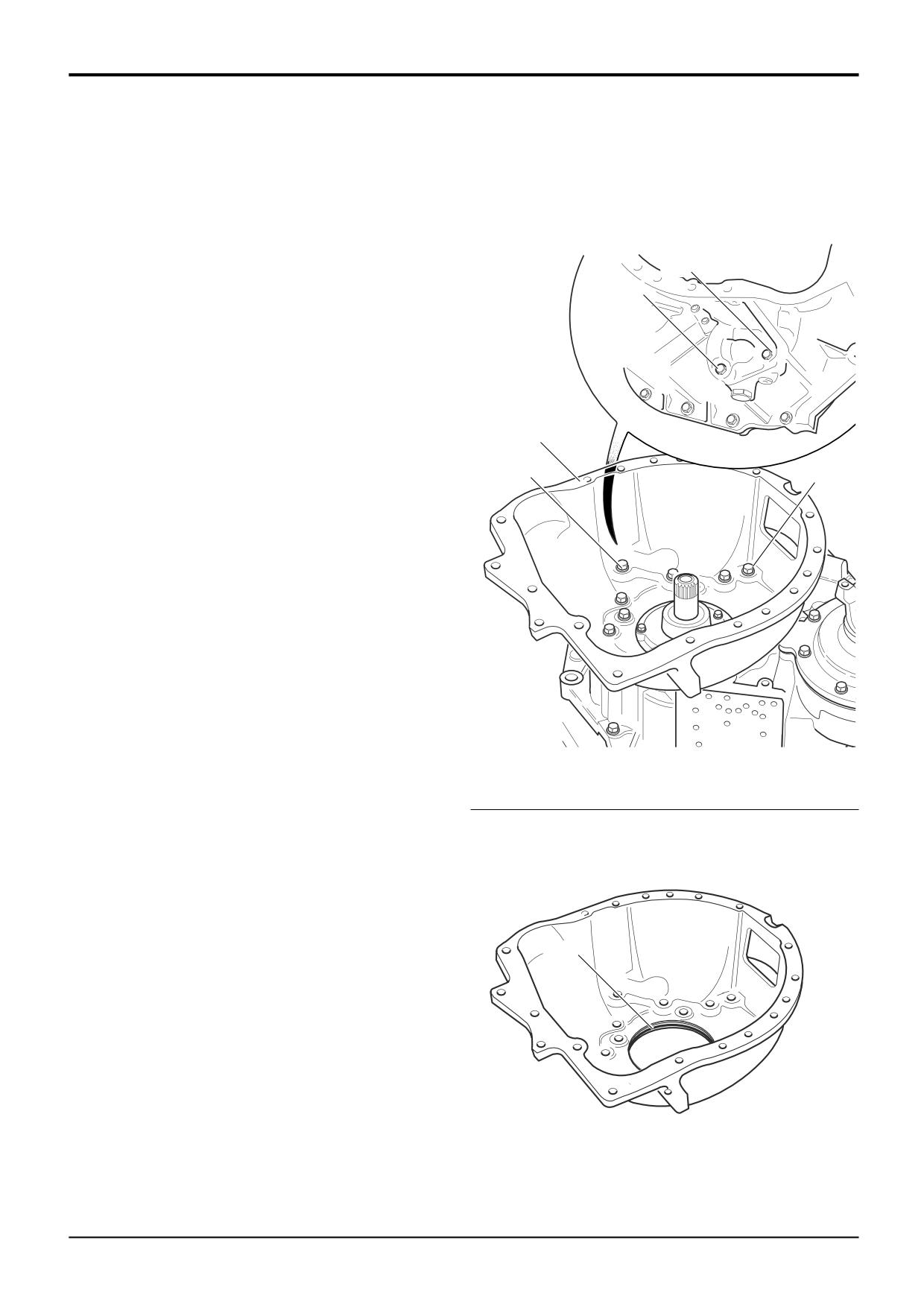
Align the Torque Converter
1
It is vitally important that the torque converter is
fitted at the gearbox and engine flywheel correctly.
Failure to locate the converter correctly will result in
damage to the gearbox oil pump on engine start up.
Proceed as follows:
Make sure that the torque converter drive dogs 1 are
correctly engaged with the pump 2 on the gearbox.
Temporarily tie the converter onto the gearbox. Use
2
wire tied at a drive plate bolt hole to a convenient point
on the outside of the gearbox.
4
Take note of the flywheel and drive plate fixing hole
phasing. The heads of the bolts 3 will foul the flywheel 4
if phasing is incorrect.
3
Before bolting the torque converter housing to the
engine make sure the mating faces are fully together
(DO NOT USE FORCE). The drive plate 8 should also
be mated close to the flywheel. Do not force the
components together with the fixing bolts.
Make sure that the torque converter is free to rotate
A396460
slightly within the clearance of the location bolt holes. If
you cannot rotate the converter it is trapped either by
bolt heads 3 or by incorrectly located pump drive
dogs.Make sure that all is well before tightening the
bolts.
4
Fill the gearbox with the specified amount and type of
oil (see Section 3, Routine Maintenance). Leave hose
N off until the filling operation is complete. After filling
refit hose N.
6
Torque Settings
5
Item
Nm
kgf m lbf ft
7
B
79
8
58
D
44
4.5
32
H
237
24
175
J,T
98
10
72
A396900
9803/3280
Issue 1
Section F
Transmission
Section F
125 - 1
Powershift Gearbox
125 - 1
1a
1a
A395250
1d
1e
1c
1b
A395260
2a
2b
3b
A395540
3a
9803/3280
Issue 1
Section F
Transmission
Section F
125 - 2
Powershift Gearbox
125 - 2
Dismantling
Note: The Dismantling, Inspection and Assembly
procedures in this manual illustrate and describe the 6x4
gearbox. Procedures for the 4x4 version of the gearbox are
indentical in most respects. Where there are differences
procedures are identified under the heading ‘4x4 Gearbox’.
With the gearbox removed from the machine, place suitable
wooden blocks to securely support the assembly.
Cleanliness is of the utmost importance when servicing the
gearbox. All precautions to prevent any ingress of dirt, grit
etc. must be taken. To this end wash the exterior of the
gearbox assembly as follows;
Make sure that all open ports and orifices are effectively
plugged. Remove any deposits of dirt, grit and oil from the
outer casings using a suitable degreaser and water. Dry the
casings.
1
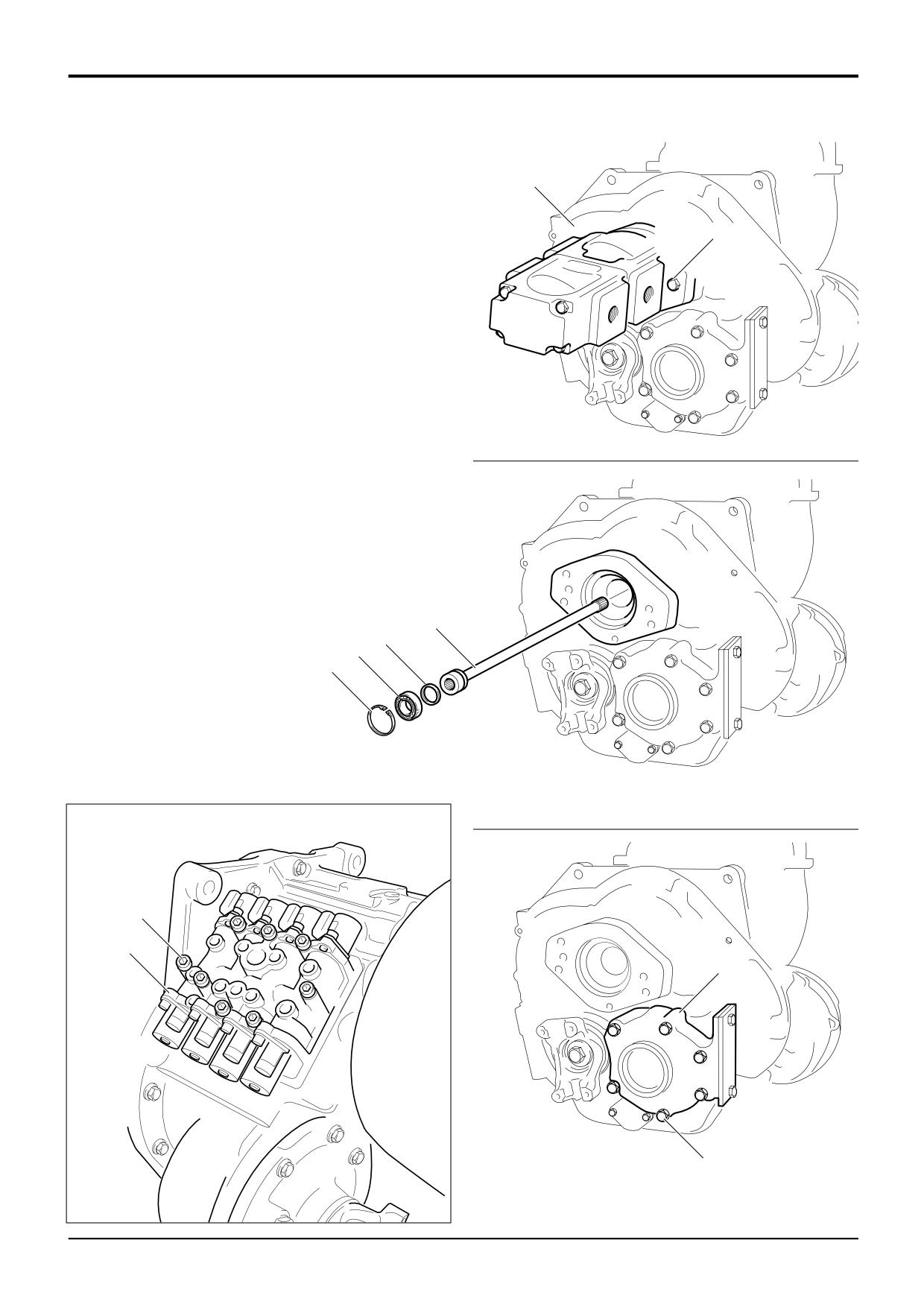
Remove the Main Hydraulic Pump and Driveshaft
a If the main hydraulic pump has not already been
removed proceed as follows. Support the pump, undo
the 2 bolts 1a. Draw the pump away from the gearbox,
disengaging the drive shaft. Lift the pump clear.
b Remove the circlip 1b followed by bearing 1c.
Withdraw the driveshaft 1d. Remove the sealing ring
1e.
2
Remove the Solenoid Control Valve Block
a Undo the 8 socket head cap screws 2a and lift off the
valve block assembly 2b. Do not use a screwdriver to
lever the block, the sealing faces will be damaged. If
the block is difficult to remove, lightly tap the manifold
block with a soft faced hammer.
Note: Some gearboxes are fitted with a valve block sub-
base plate. Be sure to retrieve the plate. The plate is thin,
make sure it is not damaged when removing. Take care not
to damage the surfaces of the plate.
b Remove and discard the valve block sealing gasket.
The gasket may disintegrate on removal, make sure all
traces are removed and discarded. Gearboxes fitted
with a sub-base plate have two gaskets, one each side
of the plate.
3
Remove the Layshaft Cover
Note: Unless the casings are to be renewed, or the gearbox
oil has been contaminated it is not necessary to remove the
cover.
a Undo the 6 bolts 3a and lift off the cover 3b.
9803/3280
Issue 1
Section F
Transmission
Section F
125 - 3
Powershift Gearbox
125 - 3
A
5a
5b
5c
5d
b
B
A396090
A395230
4a
4a
6b
6g
6a
6b
6c
4a
5b
6d
4b
6f
A395240
A395330
9803/3280
Issue 1
Section F
Transmission
Section F
125 - 4
Powershift Gearbox
125 - 4
Dismantling (cont’d)
Using suitable lifting equipment locate the gearbox in a work
cradle (892/01082) as shown at A. Clamp the gearbox in
position at the 3 clamping points on the rear casing as
shown at B. DO NOT ATTEMPT TO DISMANTLE THE
GEARBOX FURTHER UNLESS IT IS SAFELY LOCATED IN A
SUITABLE WORK CRADLE.
4
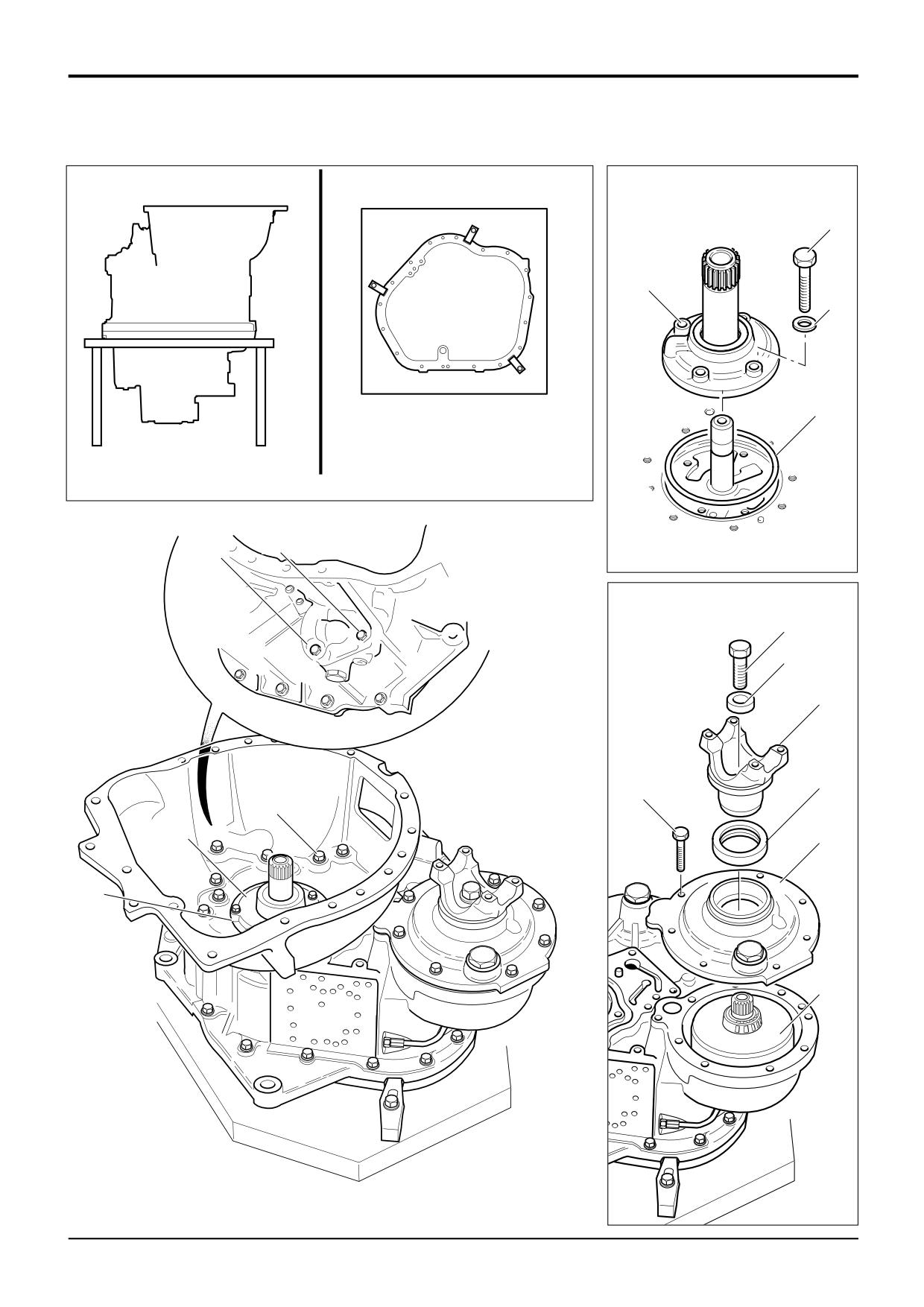
Remove the Torque Converter Housing
*
a Undo the bolts 4a†. Note that 2 bolts are located on the
outside of the housing just above the oil filter mounting.
Lift off the housing. Retrieve the sealing ‘O’ ring 4b.
†Early gearboxes feature a total of 18 bolts while late
gearboxes have 23 bolts
5
Remove the Gearbox Hydraulic Pump
a Undo the 4 fixing bolts 5a and lift the pump assembly
5b off the input shaft. Retrieve the 4 sealing washers 5c
and pump sealing ring 5d.
Note: A pump which is worn or damaged may have caused
further damage to the gearbox. Dismantle and inspect the
gearbox fully. For details of dismantling and inspecting the
pump, see Powershift Gearbox - Inspection.
6
Remove the 4WD Clutch Assembly
a Using service tool 892/00812 hold the output yoke 6a
and at the same time undo the bolt 6b. The bolt is very
tight, the help of an assistant will be required.
b Remove the thick washer 6g and yoke 6a. Undo the 8
bolts 6c and lift off the cover 6d, be sure to retrieve the
bearing outer cup from inside the cover. Remove the
output shaft oil seal 6b. Take care not to damage the
seal housing.
c Lift the clutch and shaft assembly 6f from the housing.
Retrieve the inner bearing outer cup from the casing.
For 4WD clutch dismantling and assembly procedure see
4WD Clutch - Dismantling and Assembly in this section.
9803/3280
Issue 2*
Section F
Transmission
Section F
125 - 5
Powershift Gearbox
125 - 5
7a
7b
9f
9g
7c
8a
8b
7d
8c
9c
9h
A395210
A396120
10f
9b
10g
9a
10h
10c
10b
10a
10e
10d
9e
9803/3280
Issue 2*
Section F
Transmission
Section F
125 - 6
Powershift Gearbox
125 - 6
Dismantling (cont’d)
7
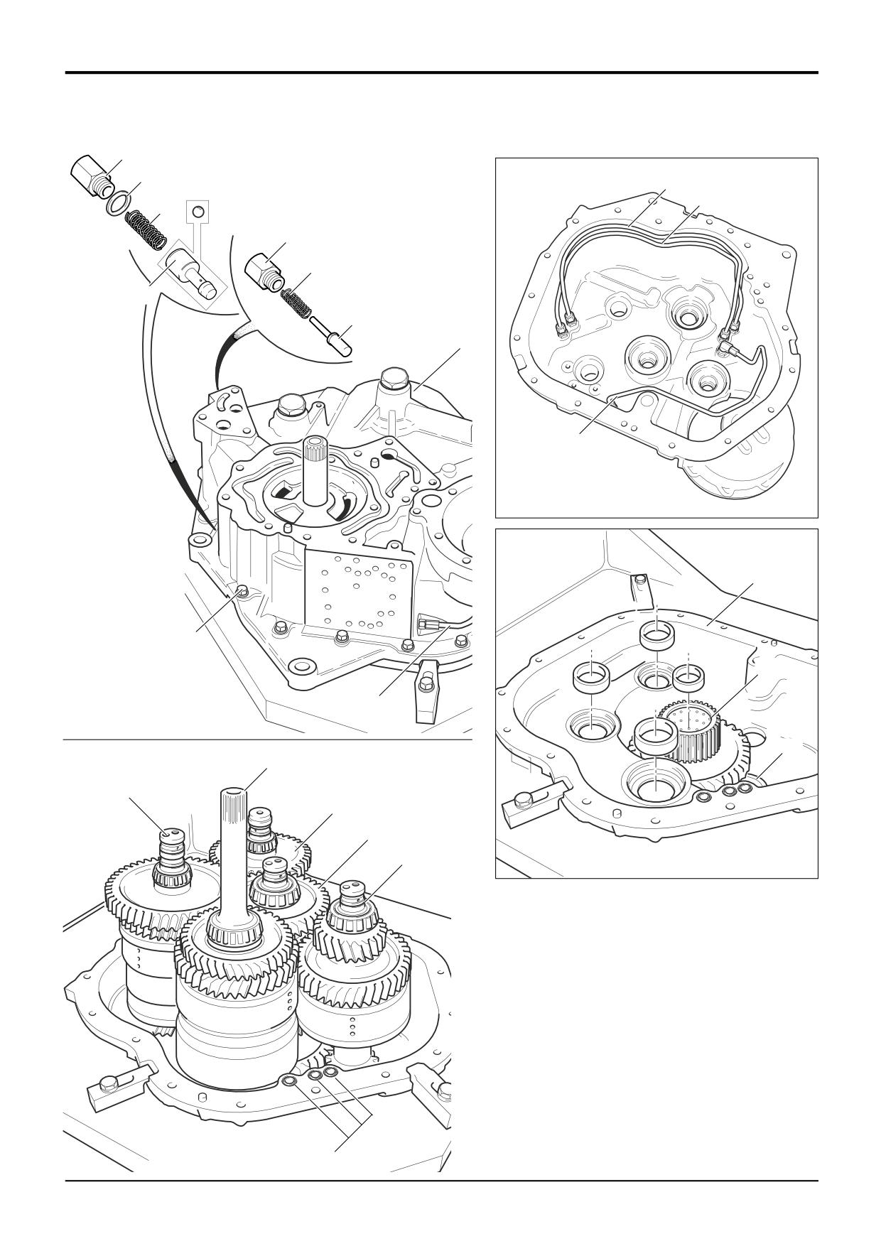
Remove the Torque Converter Relief Valve
a Undo the plug 7a and remove the sealing washer 7b,
*
spring 7c and poppet 7d. Note that some gearboxes
are fitted with a ball instead of a poppet.
8
Remove the Pressure Maintenance Valve
a Undo the plug 8a, remove spring 8b and valve spool
8c.
9
Separate the Front and Rear Casings
a Remove the 4WD clutch oil pipe 9a.
b Undo the 17 casing bolts 9b.
c Using suitable lifting equipment carefully lift off the front
case 9c. Be sure to retrieve all the shaft bearing outer
cups. The cups may be left on the bearings, or inside
the front case. Keep the cups with their associated
bearings.
d Remove and discard the 3 sealing ‘O’ rings 9e from the
front case.
Note: The 3 oil transfer pipes 9f, 9g and 9h located inside
the front case need not be removed unless they are
damaged, or the gearbox oil has been contaminated. If they
are to be removed see Powershift Gearbox - Inspection.
4x4 Gearbox: pipe 9h not fitted.
10
Remove the Clutch/Shaft Assemblies
a Carefully lift out the clutch/shaft assemblies in the
following order:
10a - 6 speed clutch shaft (not fitted to 4x4 Gearbox)
10b - Reverse clutch unit
10c - Forward/Input clutch shaft
10d - Layshaft clutch
10e - Mainshaft clutch
b Retrieve the bearing outer cups from the rear case 10f
and centre of the transfer gear 10g. Note that the
layshaft bearing cup 10h can not be removed until the
transfer gear/output shaft has been removed, see step
11. Keep the cups together with their associated
bearings.
9803/3280
Issue 2*
Section F
Transmission
Section F
125 - 7
Powershift Gearbox
125 - 7
11c
11d
11b
11r
11g
11h
11j
11p
11m
11k
11f
11e
11a
A395280
9803/3280
Issue 1
Section F
Transmission
Section F
125 - 8
Powershift Gearbox
125 - 8
Dismantling (cont’d)
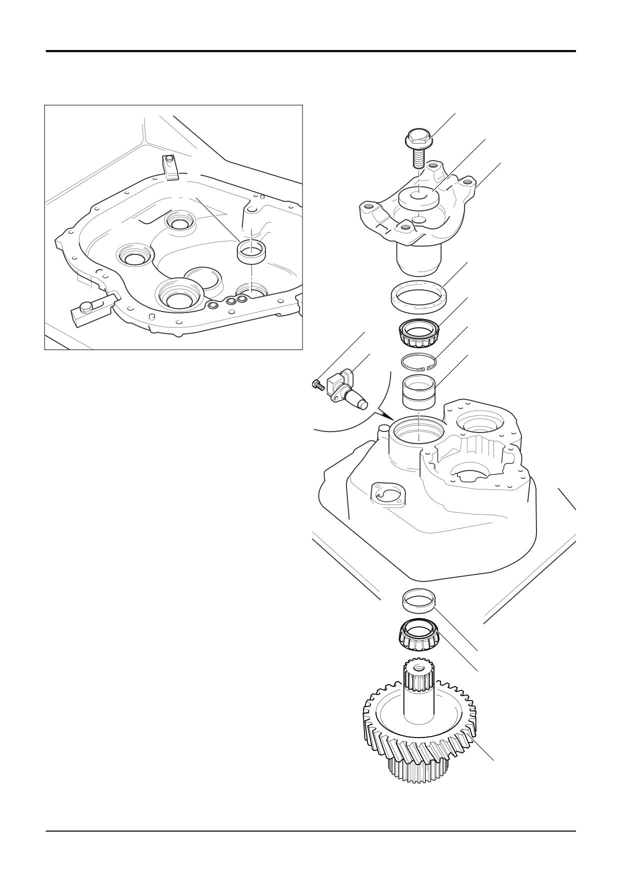
11 Remove the Transfer Gear
b Using service tool 892/00812 hold the output yoke 11b
and at the same time undo the bolt 11c. The bolt is very
tight, the help of an assistant will be required. Remove
the bolt, thick washer 11d followed by the yoke.
c Remove and discard the oil seal 11g. Take care not to
damage the seal housing.
d Support the transfer gear/shaft assembly 11a.
Withdraw the gear from inside the casing. The
assembly will lift away complete with the inner taper
roller bearing 11e and spacer 11f.
e Remove the outer taper roller bearing 11h.
f
Remove circlip 11j followed by bearing double outer
cup 11k.
Note: The inner and outer taper roller bearing assembly
(comprising double outer cup 11k, inner bearing 11e, spacer
11f and outer bearing 11h) is a matched set. Keep all the
components together in their original relationships.
Components from another set are not interchangeable. If
any components are worn or damaged the whole assembly
must be renewed as a complete matched set.
g Retrieve the layshaft bearing outer cup 11r from the
rear casing.
h If the speed sensor 11m is to be removed, undo bolt
11p and withdraw the sensor together with its sealing
‘O’ ring.
9803/3280
Issue 1
Section F
Transmission
Section F
126 - 1
Powershift Gearbox
126 - 1
Inspection
4a
4b
A395290
5a
5b
5c
A395210
5e
5f
A395110
9803/3280
Issue 1
Section F
Transmission
Section F
126 - 2
Powershift Gearbox
126 - 2
Inspection
Before assembling the gearbox, make sure that a thorough
b If the existing pump is to be re-installed proceed as
inspection of all components is carried out. Remember that
follows;
although a failed component may be easy to identify, the
Undo the security screw 4a and separate the pump
cause of that failure may be less easy to trace. It is also
body. Carefully inspect the gear teeth, white metal
possible that a failed component may have caused damage
bearing and gear/body mating faces for signs of wear
to other areas of the gearbox.
and damage, (If either is evident, the pump must be
renewed).
1
Cleaning
Carefully remove and discard the oil seal 4b. Take care
not to damage the seal housing. Fit a new seal and
a Carefully remove all traces of gasket or gasket
then re-assemble the pump.
compound from the following components:
c Make sure that pump the mating face on the gearbox
Note: When removing gasket compound use a gasket
*
front cover is clean and free from surface damage.
removal product such as Loctite Chisel. Take care not to
damage the mating faces. Clean the faces with a fine
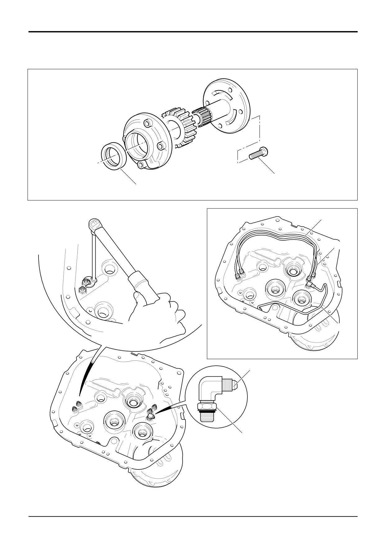
5
Oil Transfer Pipes
carborundum paper. Use a solvent cleaner and a clean cloth
to finally remove all traces of oil or debris.
The front case incorporates oil transfer pipes 5a, 5b and 5c.
If the pipes are damaged or if the gearbox has been
Front and rear casing mating faces.
contaminated, the pipes must be removed for cleaning or
Front casing and torque converter housing mating
renewal.
faces.
4x4 Gearbox: pipe 5c not fitted.
Main hydraulic pump and rear casing mating faces.
Solenoid control valve manifold and casing mating
a Using a ‘crows foot’ type spanner and a ratchet wrench
faces.
undo the pipes from the adaptors in the casing. Unless
4WD casing mating faces.
pipes are being transferred to a new casing it will not
Layshaft cover and rear casing mating faces.
be necessary to remove the pipe adaptors.
Pressure maintenance valve bore (front case)
6x4 Gearbox Only: If the adaptors are to be removed,
adaptor 5e must be removed last.
b Clean the inside of the casings using a suitable
degreasing agent.
b If the adaptors have been removed make sure that the
sealing rings are renewed and fitted correctly.
2
General Inspection
6x4 Gearbox Only: Position the lock nut 5f on adaptor
5e as shown and then fit the adaptor to the case.
a Carefully inspect all gears, bearings and shafts for signs
Screw in until the locking nut reaches the case. Do not
of excessive wear or damage. If wear or damage is
tighten the locking nut down at this stage.
evident, components must be renewed.
All Gearboxes: Fit the adaptors. Torque tighten to
70 Nm.
Note: The transfer gear shaft inner, outer bearing and
spacer assembly is a matched set. If any of the components
c Make sure the pipes are clear and free from debris
are damaged or worn the complete assembly must be
before refitting. Loosly fit the pipes 5a and 5b. Make
renewed. Components are not interchangeable between
sure they are fitted at the correct adaptors as shown.
bearing sets.
6x4 Gearbox Only: Loosly fit the pipe 5c, rotate
adaptor 5e so that the pipe is not strained. Torque
b Make sure that all oil way cross drillings are clear and
tighten down the lock nut 5f to 70 Nm.
free from debris. Blocked oil ways are a common cause
All Gearboxes: Torque tighten the pipes to 30 Nm.
of bearing failure. If necessary use an air line to blow
through the oil ways.
6
Casings
3
Clutch Units
If the gearbox casings are to be renewed, be sure to fit
blanking plugs and adapters as required. Inspect the original
a If clutch failure is suspected see the relevant clutch
casings and identify the blanking plug and adapter positions.
dismantling and assembly procedure in this section.
Transfer the plugs and adapters to the new casings. Apply
JCB Threadlocker and Sealer to the threads.
4
Gearbox Hydraulic Pump
a If tests have shown the pump performance to be
Note that new plugs may be supplied with a sealant ‘patch’,
unacceptable, the pump must be renewed as a
in which case sealant need not be applied.
complete unit.
Note: Early gearboxes feature a ‘18 bolt fix’ torque converter
*
housing. It is strongly recommended that a new ‘23 bolt fix’
housing and matching front case is fitted on assembly of the
gearbox. A compatible torque converter relief valve will also
be required.
9803/3280
Issue 3*
Section F
Transmission
Section F
127 - 1
Powershift Gearbox
127 - 1
1k
B
1j
1b
1h
1a
1g
1b
1f
1a
1b
11f
1a
D
A396070
C
1e
1c
1d
A395280
9803/3280
Issue 1
Section F
Transmission
Section F
127 - 2
Powershift Gearbox
127 - 2
Assembly
2
Checking Transfer Gear/Output Shaft
Using suitable lifting equipment locate the gearbox rear
casing in a work cradle. Clamp the casing in position at the 3
Assembly End Float
clamping points as shown at A.
DO NOT ATTEMPT TO ASSEMBLE THE GEARBOX UNLESS
The transfer gear/output shaft and its associated
IT IS SAFELY LOCATED IN A SUITABLE WORK CRADLE.
components are manufactured using a ‘Setright’ system.
Measure the rolling torque at the yoke 1h. Provided
Where ‘oil’ is referred to, use new, clean transmission oil of
components have been assembled correctly the torque will
the correct specification for the gearbox. See Section 3,
be between 0.6 and 2.2 Nm (0.5 and 1.6 lbf ft).
Lubricants and Capacities.
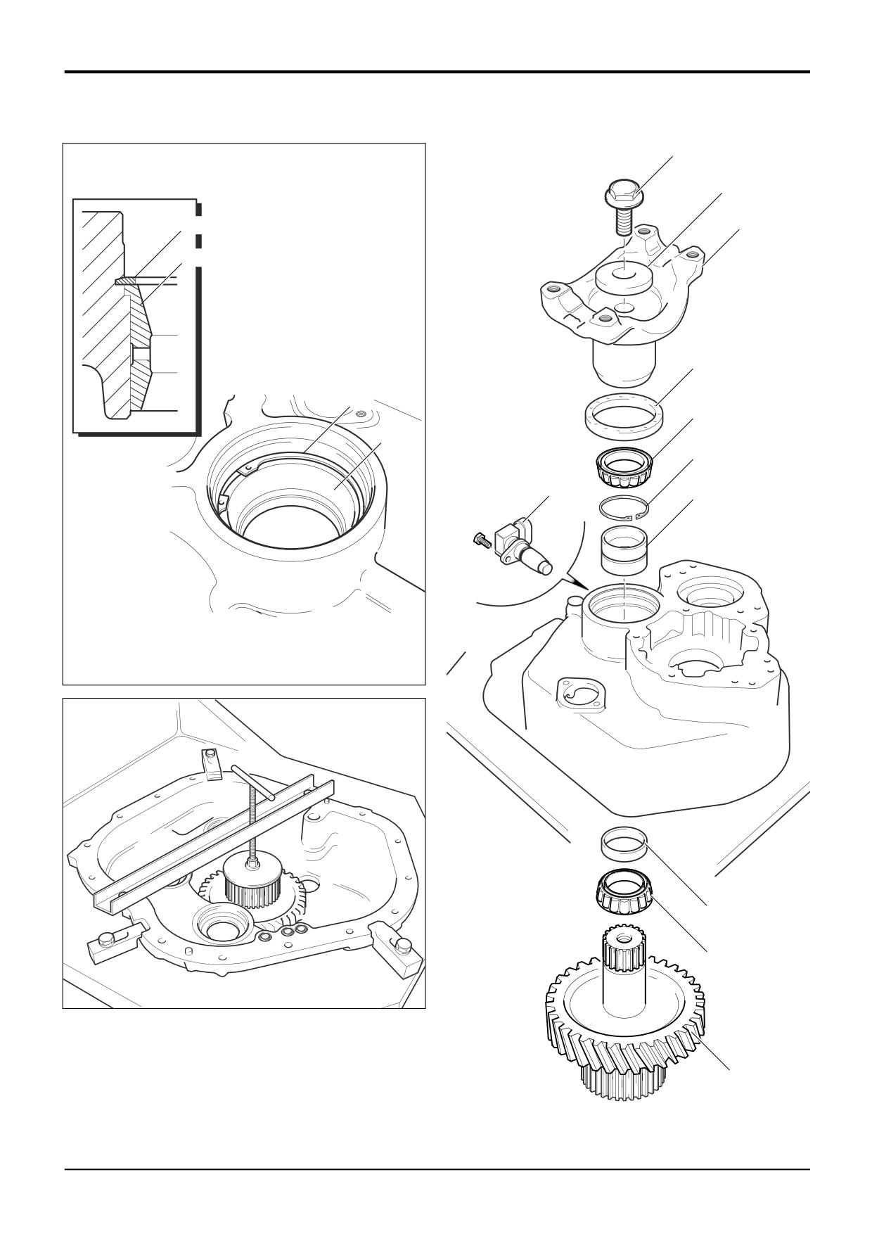
1
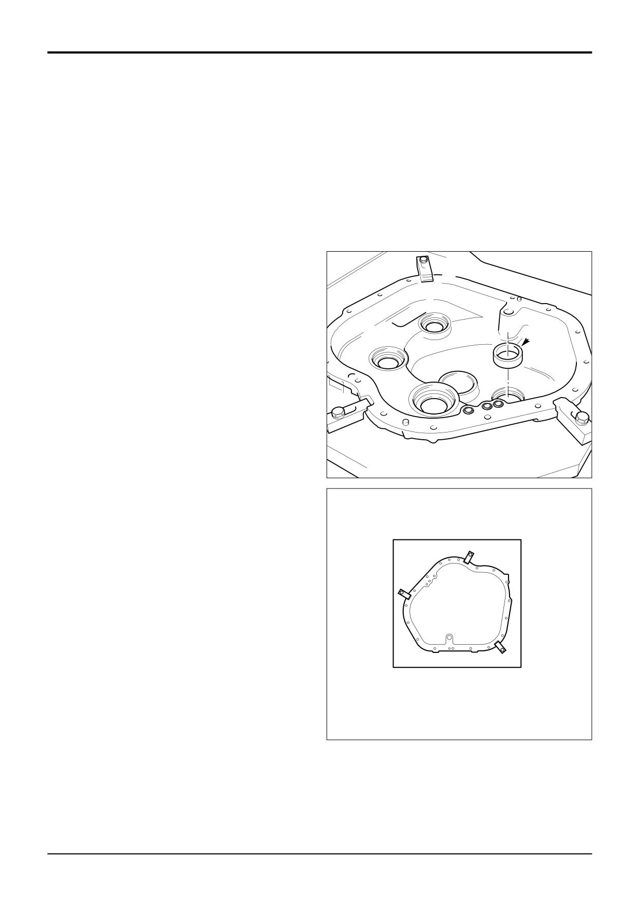
Assemble the Transfer Gear/Output Shaft
Note 1: Before fitting the transfer gear/output shaft assembly
1d, fit the layshaft outer bearing cup to the casing (shown at
E).
Position the casing as shown at D.
Note 2: The inner and outer taper roller bearing assembly
(comprising double outer cup 1a, inner bearing 1c, spacer 1e
E
and outer bearing 1f) is a matched set. Keep all the
components together in their original relationships.
Components from another set are not interchangeable. If any
components are worn or damaged the whole assembly must
be renewed as a complete matched set.
a Make sure that you have fitted the layshaft outer bearing
cup, see Note 1 above. Fit the bearing double outer cup
1a into the casing. Note the correct way up of circlip 1b,
with the chamfer uppermost. Make sure that the circlip
A395580
locates fully in its groove as shown at B. The tangs of
the circlip must not overhang the inner diameter of the
bearing cup 1a. An incorrectly located circlip can foul
and damage the outer bearing.
A
b Push the inner bearing 1c onto the transfer gear/shaft
1d followed by spacer 1e.
d Locate the transfer gear assembly in the casing from
inside. Using service tool 892/01083 retain the gear in
position (shown at C). If the gear is not held in position
the bearings may be damaged during assembly.
c Using service tool 892/01084 push on the outer bearing
1f. Using service tool 892/01085 fit a new oil seal 1g.
Make sure the seal is pushed square to the housing.
e Fit yoke 1h followed by thick washer 1j and bolt 1k. Hold
the yoke using service tool 892/00812 and torque
tighten the bolt to 400 Nm (295 lbf ft).
f
If applicable fit the speed sensor 11f. Make sure that the
sealing ‘O’ ring is correctly located and then torque
A396090
tighten the bolt to 28Nm (20 lbf ft).
9803/3280
Issue 1
Section F
Transmission
Section F
127 - 3
Powershift Gearbox
127 - 3
A
3e
3e
3f
3g
3c
3d
A396050
3a
3b
4a
A395060
B
A395620
4b
4c
4b
A335160
A395210
9803/3280
Issue 1
Section F
Transmission
Section F
127 - 4
Powershift Gearbox
127 - 4
Assembly (cont’d)
3
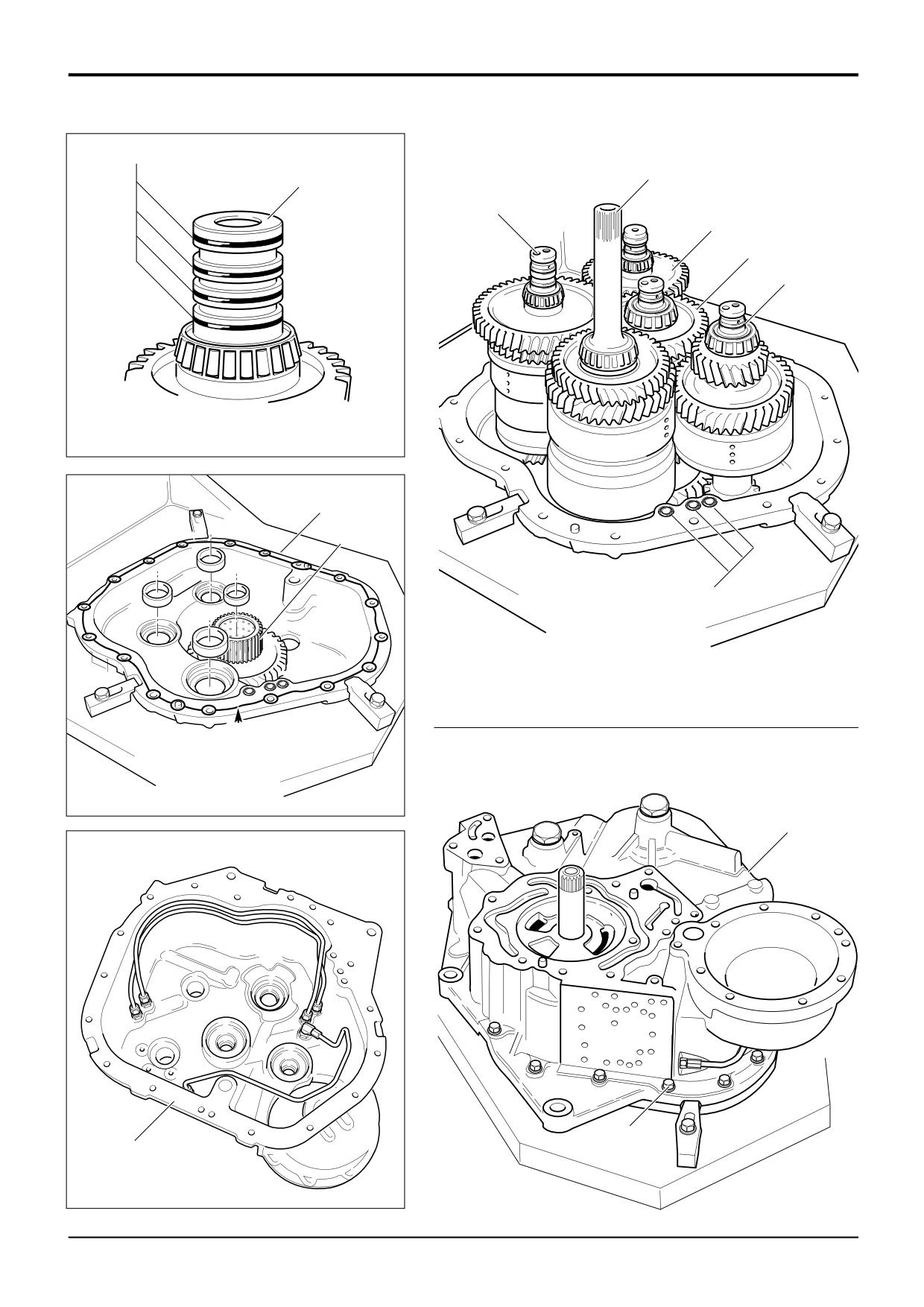
Fit the Clutch/Shaft Assemblies
a Fit the bearing outer cups at their correct locations in the
rear case 3a and centre of the transfer gear 3b.
b Carefully fit the clutch/shaft assemblies in the following
order:
Note: When fitting the layshaft clutch take care not to
damage the rear bearing on the transfer gear teeth.
Note: Before fitting the input clutch shaft make sure that the
4 sealing rings (shown at A) are in good condition and
lubricated with oil.
3c - Mainshaft clutch
3d - Layshaft clutch
3e - Forward/Input clutch shaft
3f - Reverse clutch unit
3g - 6 speed clutch shaft (not fitted to 4x4 Gearbox)
c Make sure that the sealing rings on the ends of the
clutch shafts 3c, 3d, 3f and 3g are in good condition and
lubricated with oil.
4x4 Gearbox: clutch 3g (6 speed) not fitted.
4
Assemble the Front and Rear Casings
a Make sure that the 3 off ‘O’ rings 4a are correctly fitted
to the rear case.
b Apply a thin bead of JCB Multigasket to the rear casing
mating face as shown at B.
c Make sure that the shaft bearing outer cups are correctly
located in the front case 4b and then carefully lower the
case over the clutch shafts until it mates with the rear
case. Do not use excessive force when fitting the case.
d Fit the 17 casing bolts 4c and progressively torque
tighten to 56 Nm (41 lbf ft).
9803/3280
Issue 1
Section F
Transmission
Section F
127 - 5
Powershift Gearbox
127 - 5
5b
5d
5e
5a
Y
X
5c
A335160
9803/3280
Issue 1
Section F
Transmission
Section F
127 - 6
Powershift Gearbox
127 - 6
Assembly (cont’d)
5
Checking the Clutch Shaft End Floats
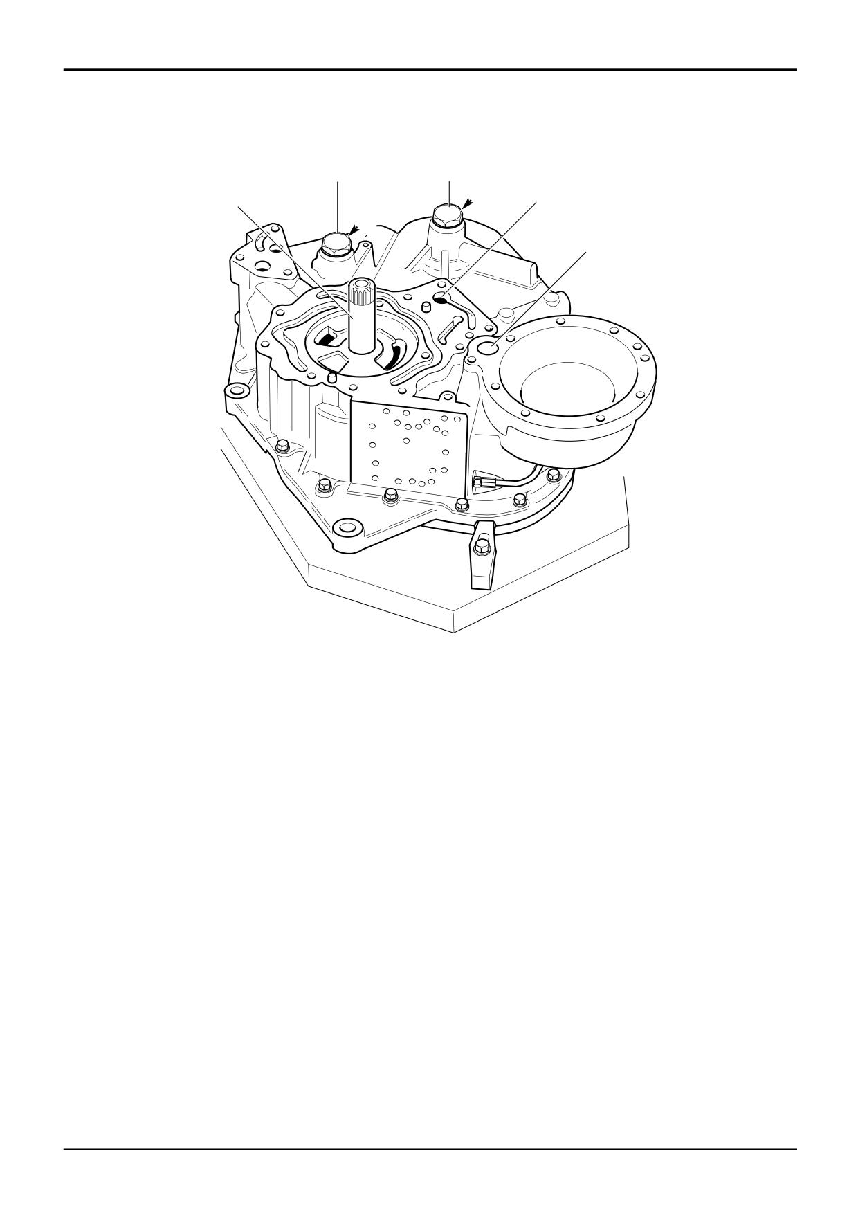
Provided components are assembled correctly the end float
will be within the limits given. Check that the shafts can be
rotated by hand (turn the input shaft and output yoke). The
shafts should rotate smoothly. The end floats can be checked
to confirm correct assembly.
End float for all shafts will be within the range 0.02 mm to
0.16 mm (0.0008 to 0.0063 in).
All shafts except the Input Shaft:
Shaft 5a - Mainshaft
Shaft 5b - Reverse clutch unit
Shaft 5c - Layshaft
Shaft 5d - 6 speed shaft (not fitted to 4x4 gearboxes)
a Remove the plugs X and Y from the front casing.
4x4 Gearbox: plug Y not fitted.
b Fit a bolt to the threaded hole in the end of the shafts.
Pull up on the bolt to detect excessive end float.
Remove the bolt.
c Apply JCB Threadlocker and Sealer to the plugs X and
Y as applicable. Torque tighten the plugs to 102 Nm
(75 lbf ft).
Input Clutch Shaft:
a Pull on the input shaft 5e to detect excessive end float.
9803/3280
Issue 1
Section F
Transmission
Section F
127 - 7
Powershift Gearbox
127 - 7
C
7c
6j
6h
7b
6g
7a
B
6e
6f
7c
8c
7b
6c
8b
7a
8a
6b
A395240
A395570
6a
A
9c
Y
9a
9d
Y
X
Y
9b
Y
A405220
A395230
9803/3280
Issue 3*
Section F
Transmission
Section F
127 - 8
Powershift Gearbox
127 - 8
Assembly (cont’d)
6
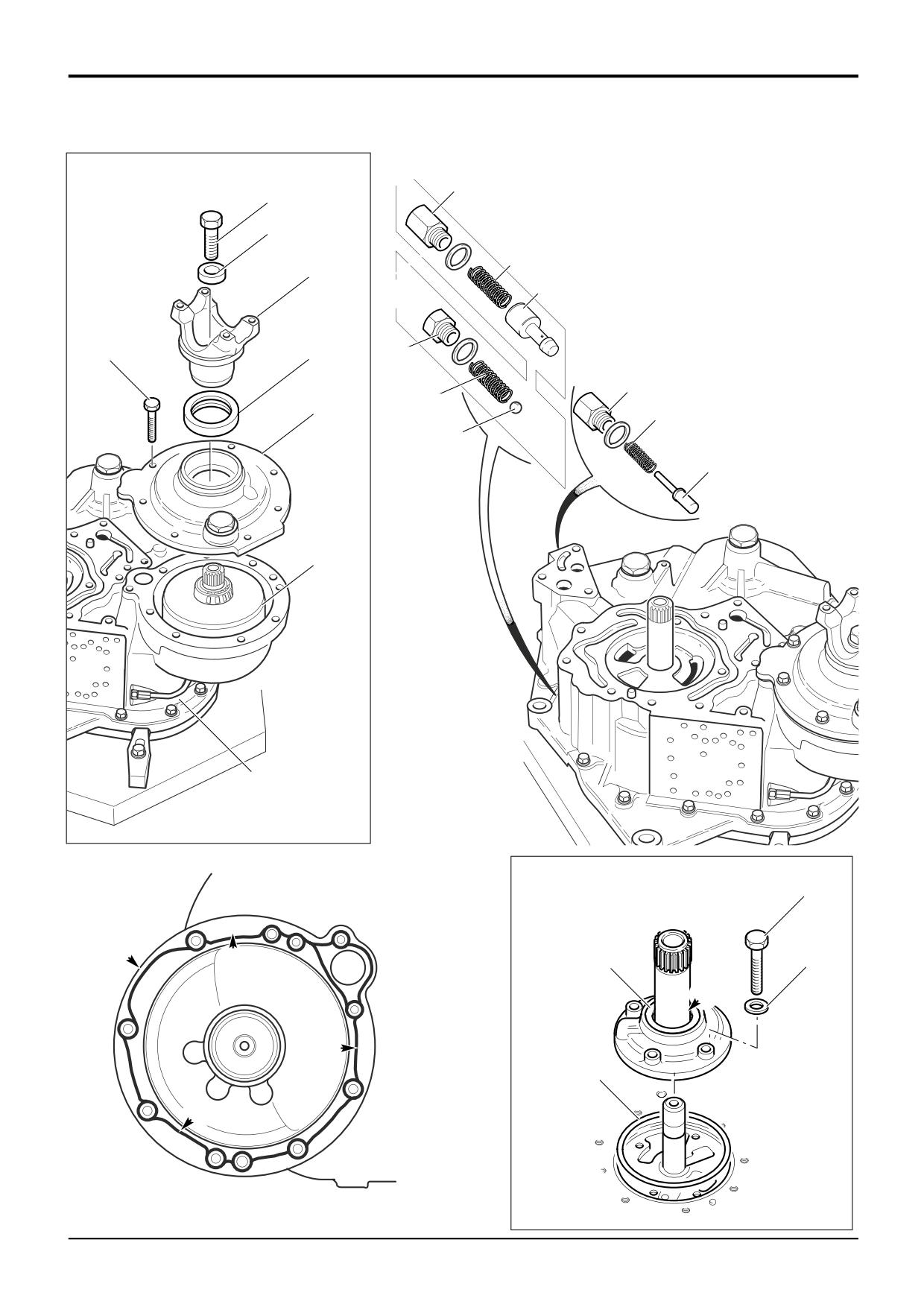
Fit the 4WD Clutch Assembly
a Fit the 4WD clutch oil feed pipe 6a at the casing.
b Make sure the shaft bearing outer cup is correctly
located in the front casing (not shown) and then locate
the clutch and shaft assembly 6b in the the housing.
c Make sure that the front and 4WD casing (6c) mating
*
faces are clean and undamaged. Apply a 3 mm bead of
Loctite 509 to the front casing as shown at A. Note that
the bead is applied near the inner or outer edge of the
flange as applicable at positions Y. Make sure that the
shaft bearing outer cup (not shown) is correctly located
inside the 4WD casing and then fit the casing. Fit 8 off
bolts 6e and progressively torque tighten to 56 Nm
Check the 4WD clutch shaft end float:
Provided components are assembled correctly the end float
will be within the limits given. Rotate the shaft by hand, it
should rotate smoothly.
The end float can be checked to confirm correct assembly.
End float must be within the range 0.01 mm to 0.16 mm
(0.0004 to 0.0063 in).
d Fit a bolt to the threaded hole in the end of the shaft. Pull
up on the bolt to detect excessive end float.
e Fit a new oil seal 6f. Make sure the seal is pushed
square to the housing.
f
Fit the output yoke 6g, followed by thick washer 6h and
bolt 6j. Hold the yoke using service tool 892/00812 and
at the same time torque tigten the bolt to 400 Nm (295
lbf ft).
7
Fit the Torque Converter Relief Valve
*
Note: The torque converter relief valve may be of a ball type
(shown at B), or poppet type (shown at C).
a Fit the ball or poppet (see note above) 7a followed by
the spring 7b. Using a new sealing washer fit plug 7c.
8
Fit the Pressure Maintenance Valve
a Oil the spool 8a and fit to the casing. Fit spring 8b. Apply
JCB Threadlocker and Sealer to the plug 8c. Using a
new sealing washer fit plug.
9
Fit the Gearbox Hydraulic Pump
a Make sure that the pump is fitted with a new oil seal 9a,
see Powershift Gearbox, Inspection, step 4.
Fit a new sealing ring 9b. Locate the pump over the
input shaft aligning the bolt holes. Apply JCB
Threadlocker and Sealer to bolts 9c. Fit the bolts
together with new sealing washers 9d. Progressively
torque tighten the bolts to 28 Nm (20 lbf ft).
b Pour some clean, new, oil into the pump at position X.
9803/3280
Issue 3*
Section F
Transmission
Section F
127 - 9
Powershift Gearbox
127 - 9
A
X
X
X
A396130
B
9
4
7
11
14
5
18
17
2
19
1
8
6
3
12
10
13
15
A402660
9803/3280
Issue 2*
Section F
Transmission
Section F
127 - 10
Powershift Gearbox
127 - 10
Assembly (cont’d)
10
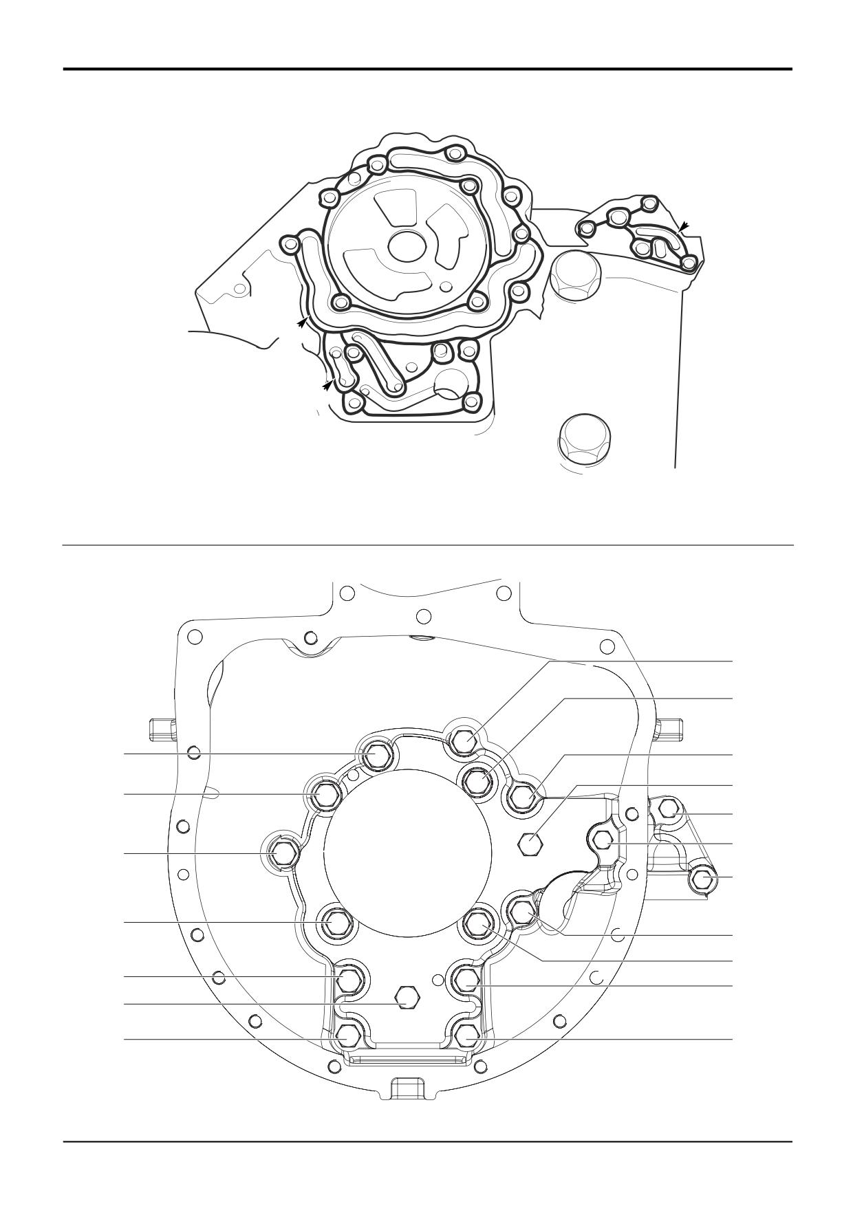
Fit the Torque Converter Housing - Gearboxes with
18 bolt fix only
*Important Note: Only the specified sealant can be used.The
10c
machine MUST NOT be operated for at least 6 hours after
sealant has been applied and the converter housing
10c
assembled. This is to allow time for the sealant to cure.
a Make sure that the front case and torque converter
housing
(10a) mating faces are clean, dry and
undamaged. Apply a 3 mm wide bead of Bondloc B574
sealant to the front casing as shown at A (pump not
shown for clarity). Make sure that sealant is applied
between all the port channels as shown. Take extra
10a
special care in the area X as sealing is critical in these
areas. Be sure not to block galleries with sealant. Fit a
new ‘O’ ring 10d to the housing 10a.
10c
10b
b Carefully locate the torque converter casing on the front
case. Fit new 10.9 grade bolts as follows:
M10 bolts 10b (15 off). Note that spacers are fitted
under bolts at positions 10 and 14.
M8 bolts 10c. (3 off)
Progressively torque tighten the bolts in the sequence
shown. Note that the bolt at position 1 is re-torqued
after tightening the bolt at position 15.
Sequence
Bolt Position
Torque
(shown at B)
Nm
lbf ft
1 - 9
1 - 9
78
57.5
10
10
60
44.25
11 - 13
11 - 13
78
57.5
14
14
60
44.25
15
15
78
57.5
16
1 (Re-torque)
78
57.5
17 - 19
17 - 19
38
28
10d
A401250
9803/3280
Issue 3*
Section F
Transmission
Section F
127 - 11
Powershift Gearbox
127 - 11
A
X
X
X
A404970
10a
B
11
Y
15
9
7
4
13
21
20
17
23
M8 x 45 mm
3
Y
1
Y
8
2
6
Y
5
16
Y
10
19
12
18
Y
14
22
M8 x 25 mm
Y
A404980
9803/3280
Issue 2*
Section F
Transmission
Section F
127 - 12
Powershift Gearbox
127 - 12
Assembly (cont’d)
10
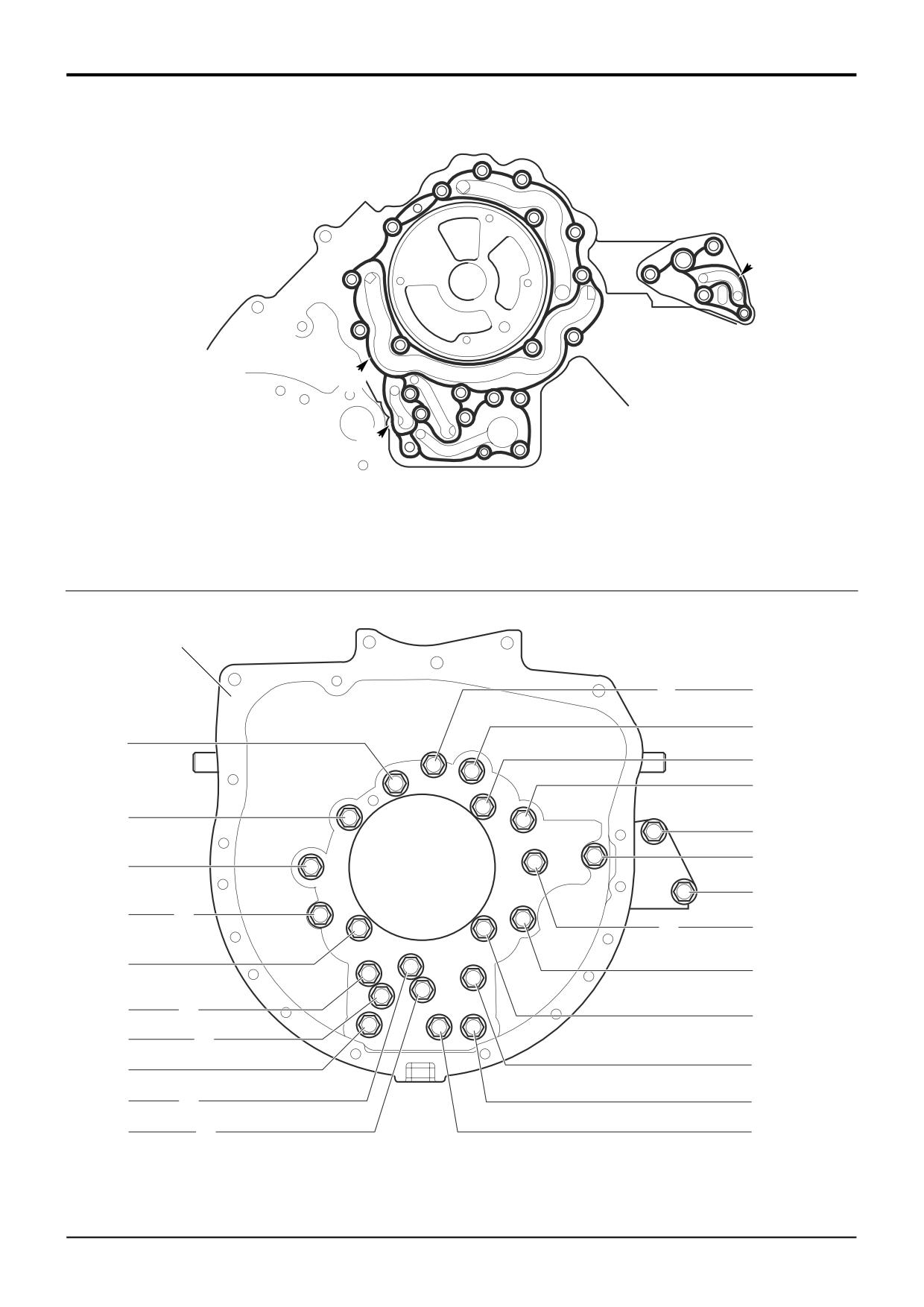
Fit the Torque Converter Housing - Gearboxes with
23 bolt fix only
Important Note: Only the specified sealant can be used. The
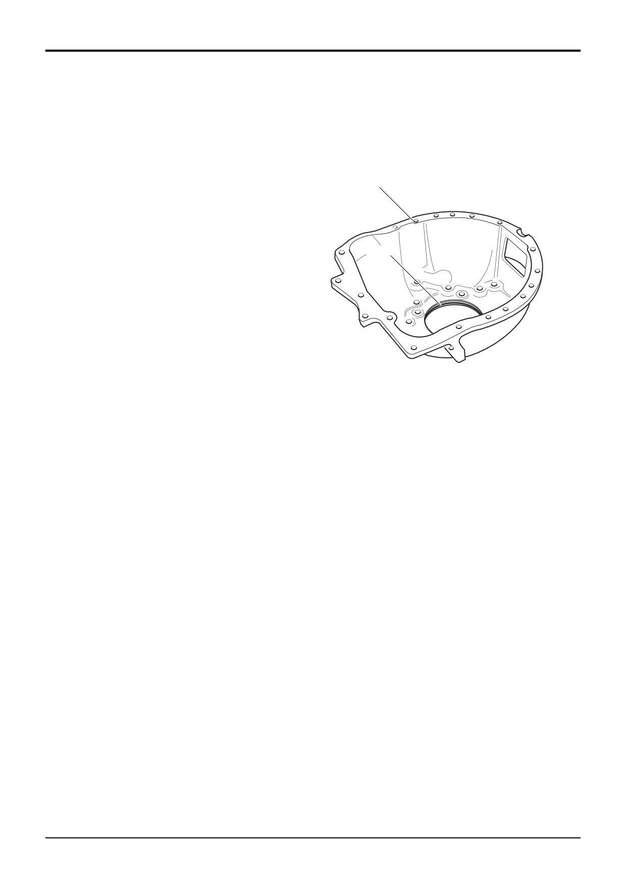
10a
machine MUST NOT be operated for at least 6 hours after
sealant has been applied and the converter housing
assembled. This is to allow time for the sealant to cure.
a Make sure that the front case and torque converter
housing
(10a) mating faces are clean, dry and
undamaged. Apply a 3 mm wide bead of Loctite 509
10d
sealant to the front casing as shown at A (pump not
shown for clarity). Make sure that sealant is applied
between all the port channels as shown. Take extra
special care at positions X as sealing is critical in these
areas. Be sure not to block galleries with sealant. Fit a
new ‘O’ ring 10d to the housing 10a.
b Carefully locate the torque converter casing on the front
case. Fit new 10.9 grade bolts (shown at B) as follows:
A401250
M10 x 35 mm bolts (21 off). Note that on some
gearboxes spacers are fitted under bolts at positions Y.
M8 x 25 mm bolt at position 22.
M8 x 45 mm bolt at position 23.
Progressively torque tighten the bolts in the sequence
shown.
Sequence
Bolt Position
Torque
(shown at B)
Nm
lbf ft
1 - 21
1 - 21
78
57.5
22 - 23
22 - 23
35 - 40 26 - 30
9803/3280
Issue 2*
Section F
Transmission
Section F
127 - 13
Powershift Gearbox
127 - 13
11b
11a
A390510
13a
12b
13b
12a
12c
A395260
12d
9803/3280
Issue 1
Section F
Transmission
Section F
127 - 14
Powershift Gearbox
127 - 14
11
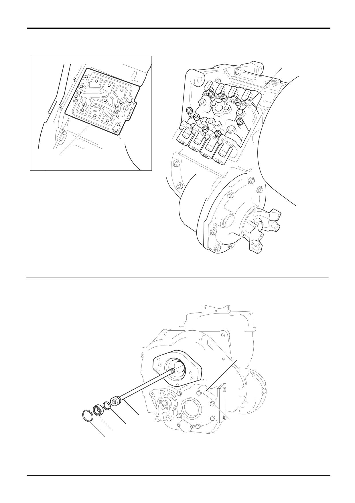
Fit the Solenoid Control Valve Block
a Fit two guide studs at the valve interface on the front
case. Locate a new valve block sealing gasket 11a as
shown at C. Care is needed as the gasket is thin.
Gearboxes fitted with a sub-base plate have two
gaskets, one each side of the plate.
b Fit the 8 socket head cap screws and washers 11b. The
screws must be progressively torque tightened.
Gradually tighten all the screws to 35 Nm (26 lbf ft).
12
Fit the Main Hydraulic Pump Driveshaft
a Fit a new sealing ring 12a to the shaft 12b. Apply clean
oil to the sealing ring and fit the shaft inside the gearbox.
b Apply clean oil to the ball bearing 12c. Fit the bearing
followed by circlip 12d.
13
Fit the Layshaft Cover
a If applicable fit the layshaft cover 13a. Make sure the
casing mating faces are clean and undamaged. Apply a
thin bead of JCB Multigasket to the rear casing and fit
the cover. Fit bolts 13b and progressively torque tighten
to 56Nm (41 lbf ft).
Note: The main machine hydraulic pump can be fitted at this
stage. However, it is easier to fit the gearbox to the machine
and then fit the pump. See Section E, Main Hydraulic
Pump, Replacement.
9803/3280
Issue 1