JCB 3CX, 4CX, 214e, 214, 215, 217 & VARIANTS Backhoe Loader. Service Manual - page 28
Section F
Transmission
Section F
94 - 2
Rear Axle - SD80, PD70
94 - 2
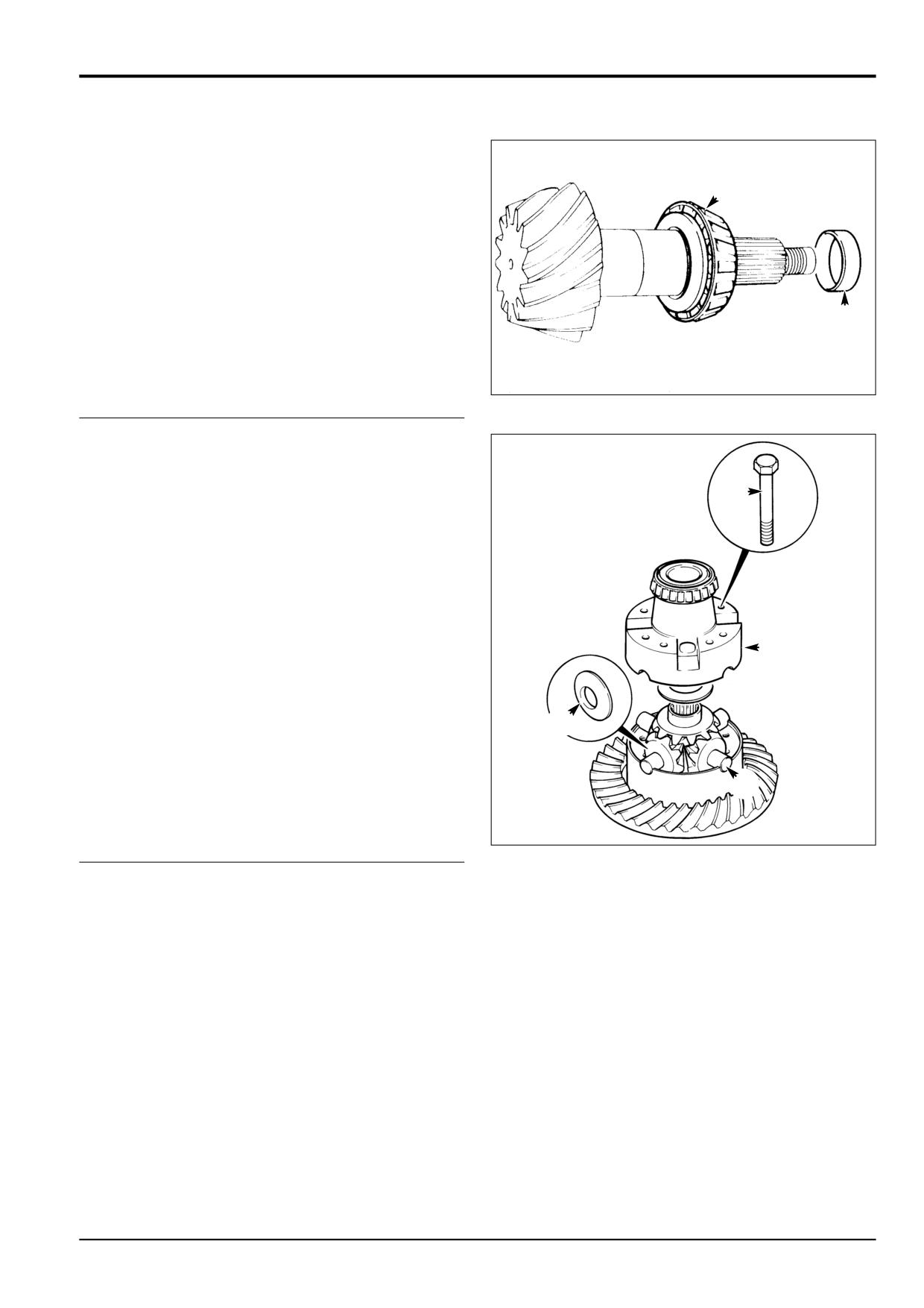
Drive Head-Dismantling (cont'd)
8
Remove the pinion spacer.
9
9
Pull off the bearing cone.
8
S256080
10 To dismantle the differential assembly, first remove bolts.
11
Lift off the top half housing.
0
12 Remove the differential gears and spherical washers. Pull
off both differential bearing cones.
!
@
@
S256100
9803/3280
Issue 1
Section F
Transmission
Section F
94 - 3
Rear Axle - SD80, PD70
94 - 3
Drive Head-Assembly
Pinion Depth
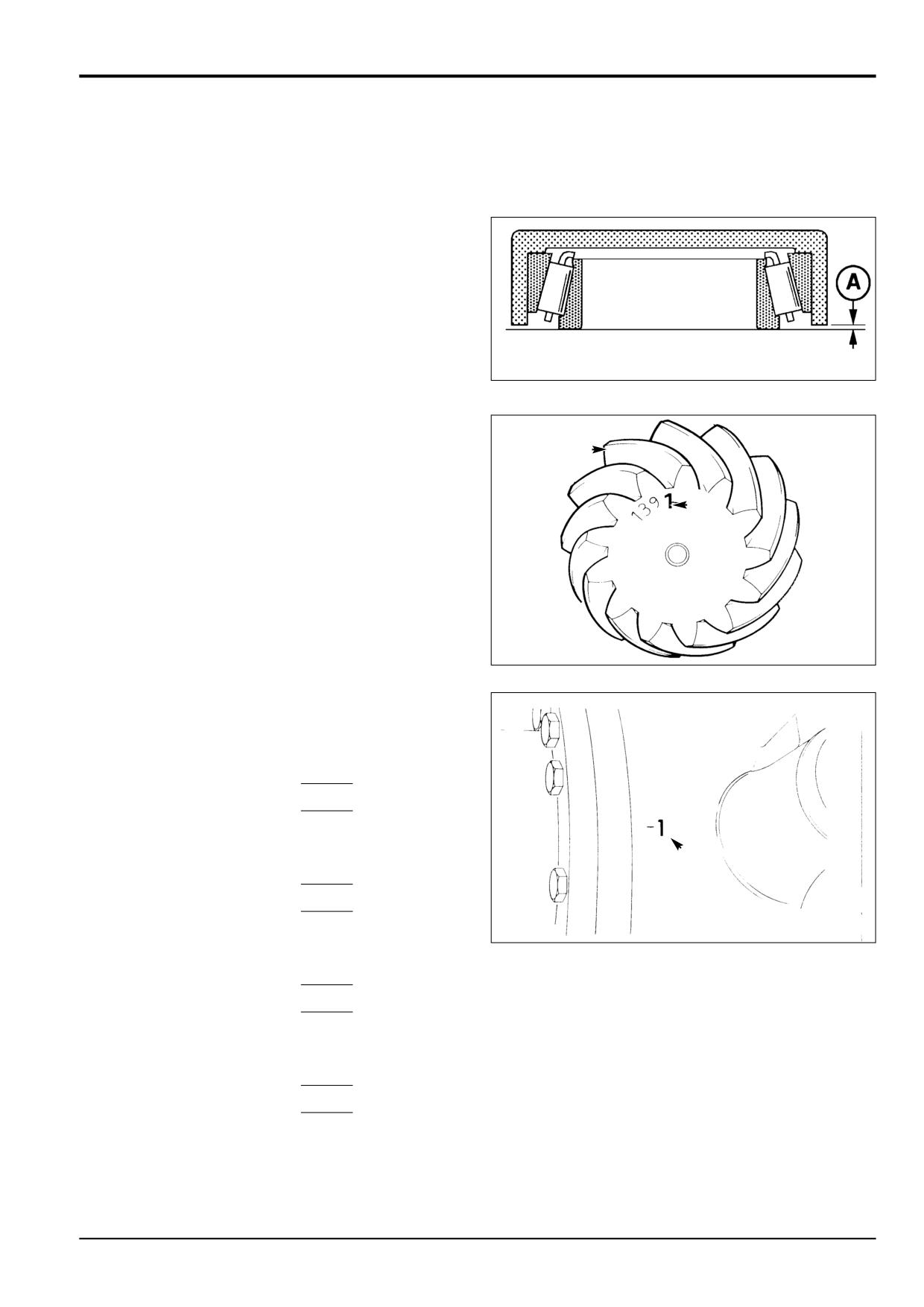
Determine the pinion depth setting as follows:
Note: See page Crownwheel and Pinion for general
guidance on crownwheel and pinion adjustment.
1
Assemble the pinion inner bearing and its cup on a flat
surface.
2
Place Service Tool 892/00174 over the bearing assembly.
Measure gap A. Add tool depth (30.01 mm) to gap A to
S184400
give bearing depth.
3
Note the mounting distance figure B etched on the pinion
and the deviation figure C on the drive head housing.
Both figures are in units of 0.01 mm.
D
Note: The pinion depth may be etched on the gear face B or
on the rear of a gear tooth D.
B
4
If dimension B is positive, add it to the bearing depth. If
dimension B is negative, subtract it from the bearing
depth.
5
If dimension C is positive, subtract it from the total. If
dimension C is negative, add it to the total.
S256110
6
Subtract the result from the standard value of 31.19 mm
to give the required shim thickness.
Example (Dimensions in mm)
Dimension A
0.25
Add tool depth
+ 30.01
Total
30.26
Add dimension B if positive.
(Subtract if negative.)
+ 0.01
C
Total
30.27
S256120
Add dimension C if negative.
(Subtract if positive.)
+ 0.01
Total
30.28
Standard Value
31.19
Less calculated total from above
- 30.28
SHIM THICKNESS
0.91
9803/3280
Issue 1
Section F
Transmission
Section F
94 - 4
Rear Axle - SD80, PD70
94 - 4
Drive Head-Assembly (cont'd)
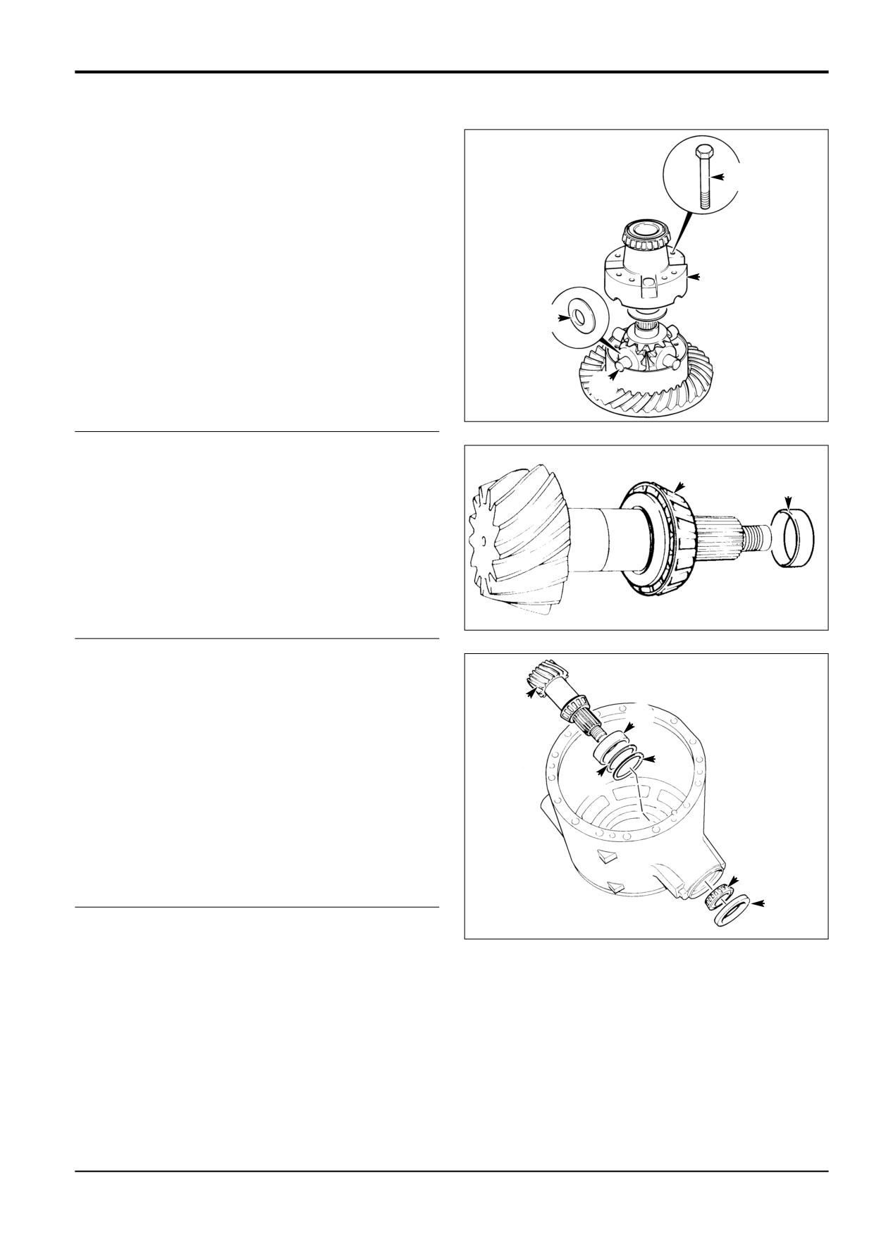
Note: The crown wheel and pinion are matched and should
be renewed as a pair if either one is damaged or excessively
8
worn. The two differential housing halves are also matched.
Do not use unmatched halves. If required, fit a new
crownwheel to the differential case half, torque tighten
crownwheel retaining bolts to 166 Nm 122 lbf ft; 17 kgf m).
7
Assemble the differential gears and their spherical
washers into the bottom half housing. Fit the differential
8
bearing cones.
7
8
Position the top half housing onto the differential,
aligning the match mark letters (see Note above). Apply
S256100
JCB Threadlocker & Sealer to the threads of bolts, then
fit and torque - tighten to 56 Nm (42 lbf ft, 6 kgf m).
Check the gears for free rotation.
7
9
Fit the pinion inner bearing cone and the largest
available spacer (e.g. 14.20 mm)
9
9
Note: It should be noted that the axle should be assembled
using a solid spacer. However, in the absence of the special
tools required or the correct size solid spacer it is acceptable
to fit a collapsible spacer, refer to Axles, Collapsible Spacer
Assembly.
S256090
10
Fit the pinion inner bearing cup, together with the
required thickness of shims to give correct pinion
depth, see Pinion Depth, steps 1 to 6. To ensure the
!
cup is fitted square, use a suitable puller assembly. Do
0
not use a hammer. Fit the outer bearing cup.
11
Insert the pinion into its bore. (Before inserting, ensure
0
that the pinion matches the crownwheel. The code
0
numbers etched on the pinion end face and the
crownwheel perimeter should be the same.
12
Fit the pinion outer bearing cone. Do not fit the oil seal
at this stage.
S256080
@
@
S256120
9803/3280
Issue 1
Section F
Transmission
Section F
94 - 5
Rear Axle - SD80, PD70
94 - 5
Drive Head-Assembly (cont'd)
C
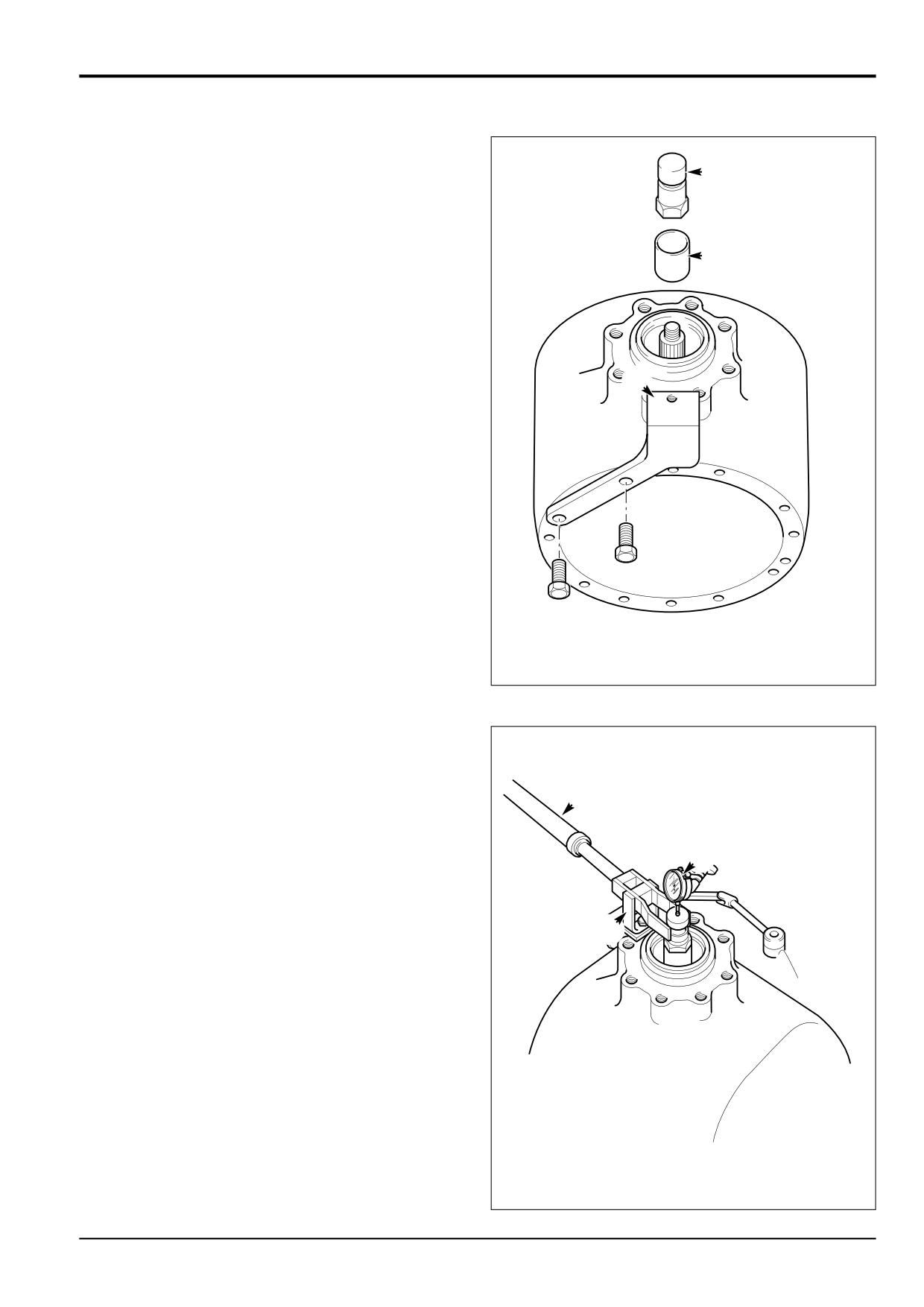
13
Fit special tool sleeve B and special pinion shaft
adapter C. Tighten adapter C to approximately 50 Nm,
making sure the pinion is free to rotate and there is end
float, this will prevent any damage to the bearing. If the
pinion is not free to rotate or there is no end float at this
B
stage check the bearing is fitted correctly. Also check
the correct size spacer has been fitted.
14
Fit special bracket D to the drive-head housing using
two M10 x 30 nuts and bolts. Fit special tool support
pillar E to bracket D so that the fork end engages in
adapter C. Ensure that fork E is centrally located on
adapter C. If necessary, re-align bracket D to suit.
Fit dial test indicator (DTI) F. Ensure that the DTI is
D
mounted on the drive head and not on bracket D.
15
Set torque wrench G to 35 Nm (25.8 lbf ft) and measure
the end float while rotating the shaft.
16
To select the right size spacer, subtract the end float
obtained at step 14 from the solid spacer size (14.20
mm). Also subtract 0.04 mm to allow for theoretical
bearing tolerance and pre load. The result is the size of
spacer to be fitted from the solid spacer setting kit. If
there is no spacer of this size, fit the next nearest size
spacer, refer to Service Tools - Axles.
A396970
Example
Temporary spacer size
14.20
Subtract end-float
0.25
Total
13.95
Subtract tolerance & preload
0.04
Result
13.91
(No spacer available this size, use next nearest size
spacer i.e 13.900)
G
17
Remove sleeve B and temporary spacer. fit correct size
spacer from solid spacer setting kit, refer to Service
Tools - Axles. During removal take care to avoid
F
damaging the outer bearing.
18
Fit sleeve B. Tighten adapter C to no more than 50 Nm
to protect against bearing damage while spacer
E
selection is verified making sure the pinion is free to
rotate. Check there is no end float and pinion is free to
turn smoothly by hand. Remove adapter C and fit nut
16. Then check that rolling torque is less than 2.0 Nm. If
the rolling torque exceeds 2.0 Nm, check that the shaft
has been assembled correctly.
Note: If the pinion is not free to rotate check the correct size
spacer has been fitted.
A396850
9803/3280
Issue 1
Section F
Transmission
Section F
94 - 6
Rear Axle - SD80, PD70
94 - 6
19
If rolling torque measured at step 18 is too high, fit the
next larger size spacer. If rolling torque is too low, fit the
next smallest size spacer. If a correct spacer is not
^
available from the range, check that drive head is
assembled correctly.
20
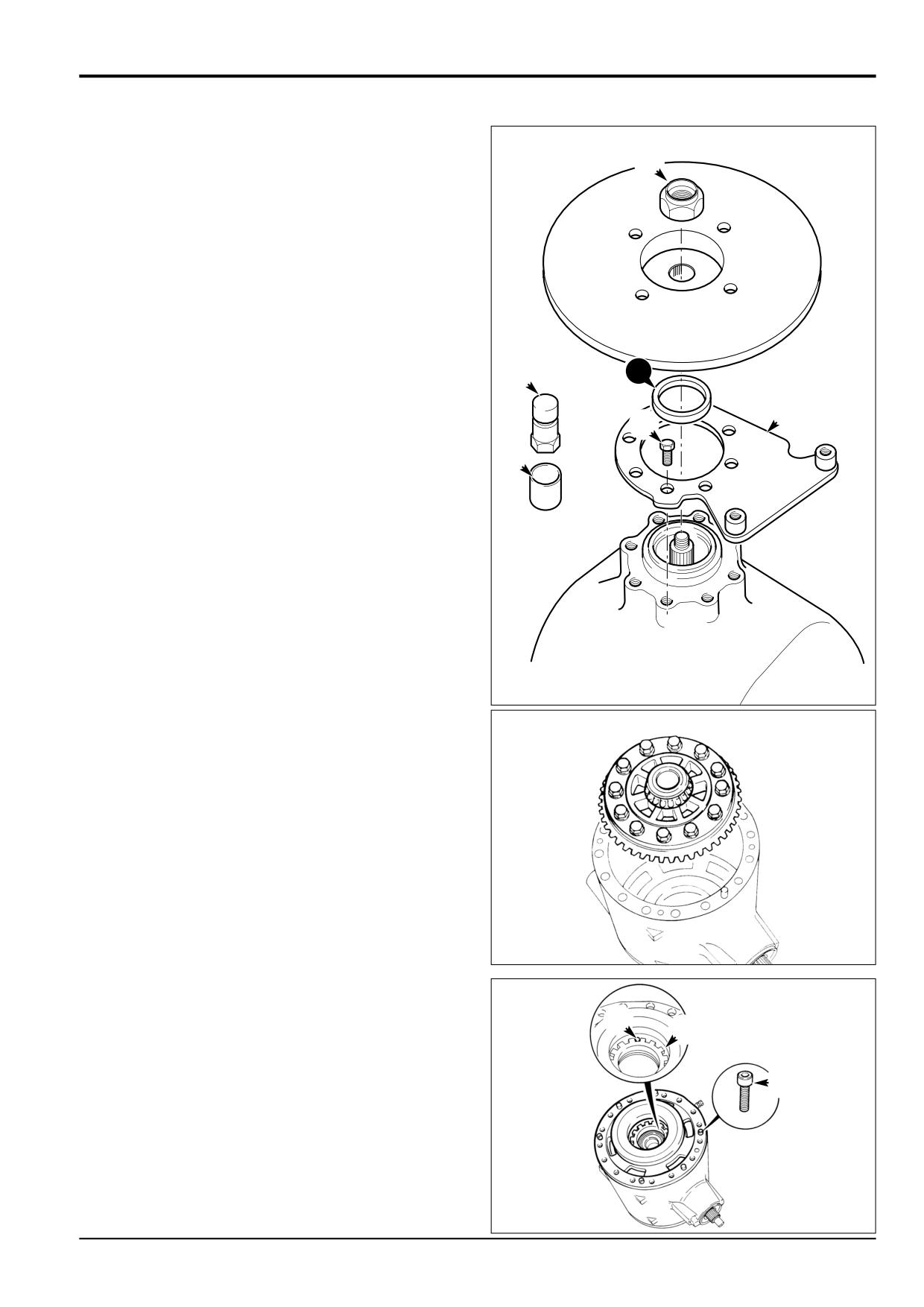
Remove adapter C and sleeve B. Fit a new oil seal,
grease between seal lips before fitting. Fit the brake
calliper bracket D. Apply JCB Threadlocker and Sealer
to the fixing bolts E. Fit the brake disc/coupling and a
NEW stake nut 16.
21
Progressively torque tighten the stake nut, occasionally
rotating coupling yoke, up to 250 Nm. Providing the
20
correct size spacer has been selected the rolling torque
C
should be between 2.3 and 3.4 Nm including seal drag.
D
E
Note: The nut tightening torque can be increased to a
maximum of 300 Nm provided that the pinion rolling torque
B
does not exceed the maximum of 3.4 Nm.
22
Finally stake the nut 16 into the slot.
A401240
23
If both brake piston housings were removed, fit the one
at the opposite end to the crownwheel, using the
procedure in Step 24. Then install the crownwheel
/differential assembly into the drive head.
S256070
24
Apply JCB Multi-Gasket to the drive head mating face,
then fit the brake piston housing. Ensure that the match
*
- marks made during dismantling are aligned. Fit
&
capscrews. Torque - tighten to 56 Nm (42 lbf ft, 5.7 kgf
m). (Applies to both piston housings.)
$
25
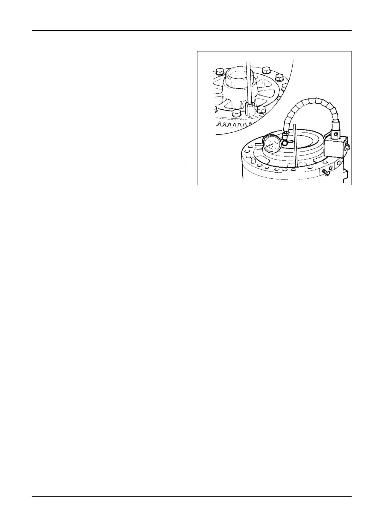
Adjust differential side nuts to give a bearing preload of
1.13-2.26 Nm (0.8-1.6 lbf ft; 0.1-0.2 kgf m). (Measure
the preload by taking another rolling torque reading and
subtracting the torque figure measured at step 21. The
difference is the bearing preload.)
S256140
9803/3280
Issue 1
Section F
Transmission
Section F
94 - 7
Rear Axle - SD80, PD70
94 - 7
26
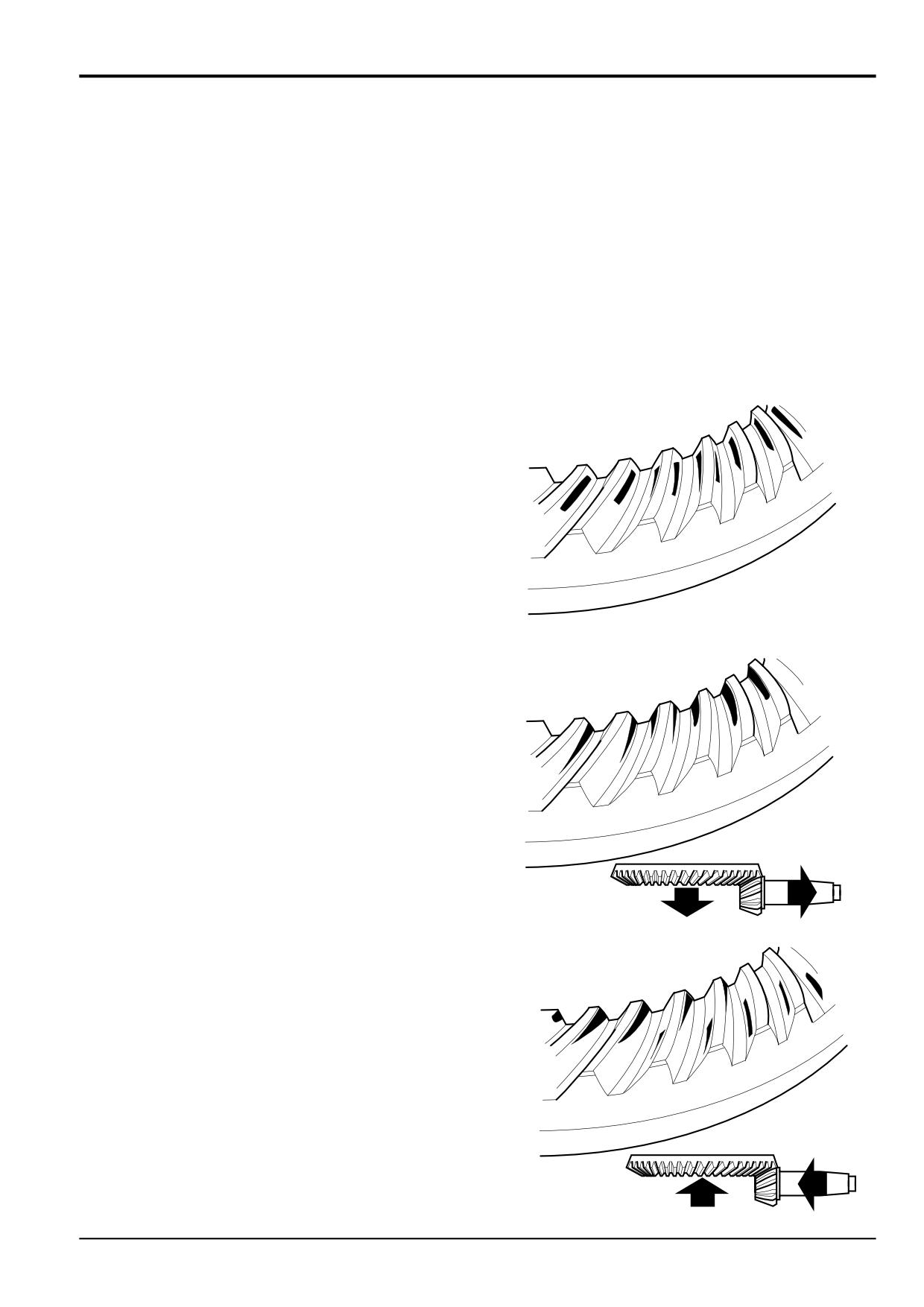
Measure the crownwheel backlash, which should be
0.17-0.28 mm (0.006-0.010 in). Adjust the differential
side nuts by equal amounts when altering backlash.
When backlash and preload are both correct, fit the
sidenut locking pins, see step 25.
S256150
9803/3280
Issue 1
Section F
Transmission
Section F
94 - 8
Rear Axle - SD80, PD70
94 - 8
Crownwheel and Pinion Meshing
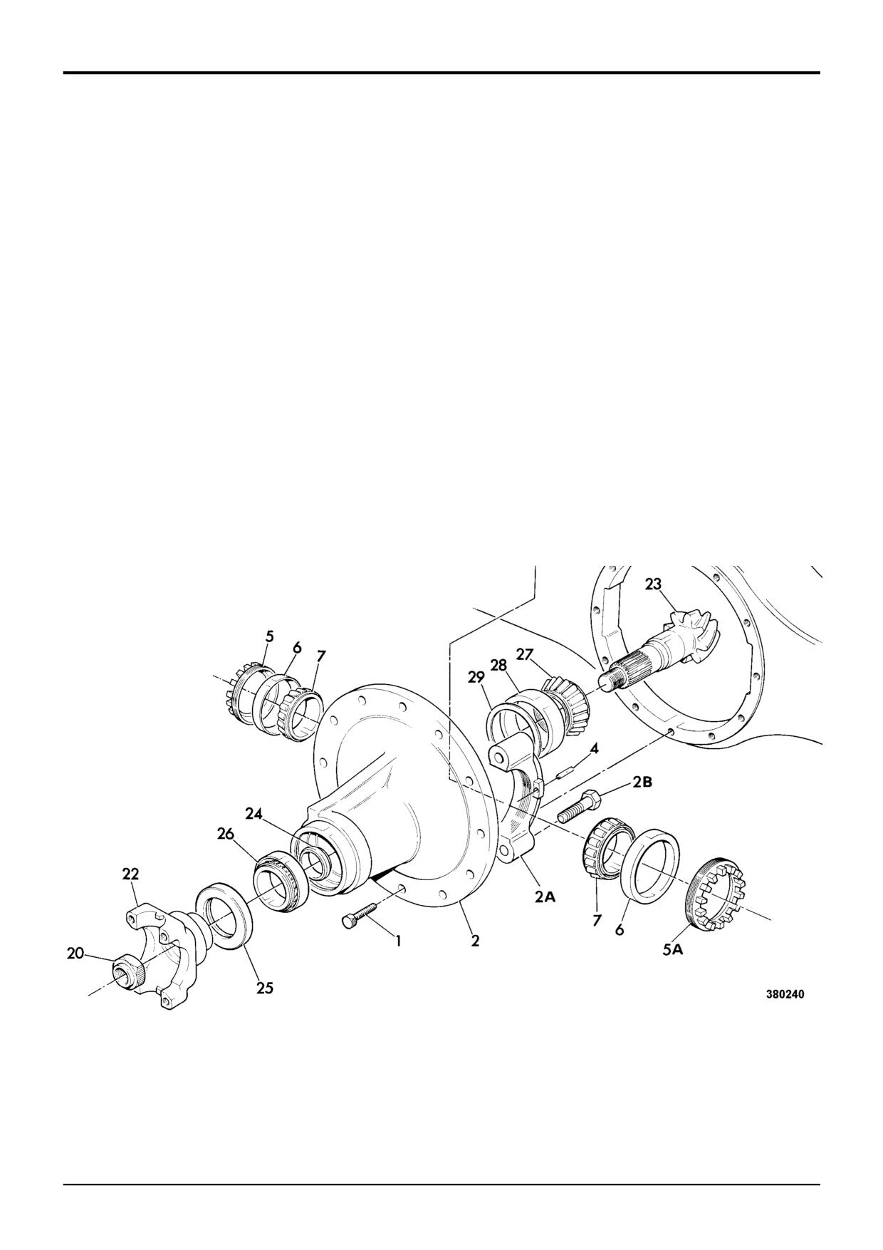
Meshing of the gears should be checked by marking three of
the pinion teeth with engineers marking compound and
rotating the pinion.
The marking will then be transferred to the crown wheel
teeth.
Correct tooth marking.
A386940
Pinion too deeply in mesh.
Decrease the shim thickness between the pinion inner
bearing cup and the axle casing. Move the crown wheel
towards the pinion to correct the backlash.
A386950
Pinion too far out of mesh.
Increase the shim thickness between the pinion inner
bearing cup and the axle casing. Move the crown wheel
away from the pinion to correct the backlash.
A386960
9803/3280
Issue 1
Section F
Transmission
Section F
95 - 1
Axles
95 - 1
Collapsible Spacer Assembly
When assembling the axle, if the special tools listed in the
Service Tools - Axles section or if the correct size solid
spacer is not available it is acceptable to fit a collapsible
spacer using the procedure below. The illustration shows a
typical axle, note that rear axles are fitted with a brake disc,
not the yoke 22 shown.
1
Smear output shaft inner bearing 27 with JCB HP
Grease before refitting. Fit bearing cup 28 over pinion
shaft 23 and assemble into drive head casing.
2
Fit NEW collapsible spacer 24, after smearing with JCB
HP Grease fit outer bearing 26 followed by a new oil seal
25. Grease between seal lips before fitting. Assemble
yoke 22 and NEW stake nut 20 with integral washer.
3
Tighten stake nut to achieve a rolling torque of 1.5 to 2.8
Nm (1.1 to 21. lbf ft), inclusive of seal drag.
Note: If this figure is accidentally exceeded the output shaft
must be dismantled and the collapsible spacer 24 renewed.
4
Finally stake nut into slot.
9803/3280
Issue 1

Section F
Transmission
Section F
100 - 1
Limited Slip Differential
100 - 1
5
6
7
8
9
1
10
14
13
12
10
9
8
7
6
3
11
4
2
S212800
S171530
S212790
9803/3280
Issue 1
Section F
Transmission
Section F
100 - 2
Limited Slip Differential
100 - 2
Dismantling and Assembly
Friction Plate Wear Limits
The numerical sequence shown on the illustration is
Measure and note the thickness of the friction plate, the
intended as a guide to dismantling
result must not be less than 1.25 mm (0.049 in).
Check the condition of the friction material, which should be
When Dismantling
even over both surfaces.
Mark the two differential halves before dismantling, for
subsequent assembly.
If in doubt, discard the set (friction and counter plates).
Torque Settings
Note the relative positions of the friction and counter plates
before dismantling, they must be fitted in the same
positions.
SD55
Item 1
94 Nm
9.6 kgf m
70 lbf ft
If worn, the friction and counter plates must be renewed as a
complete set.
SD70, PD70, SD80
Item 1
166 Nm
16.9 kgf m
122 lbf ft
When Assembling
1
Assemble trunnion pins 12, side gears 11 with pressure
plates 10, counter plates 8, friction plates 9, planet
gears 13 and thrust washers 14 into the 'crownwheel
half of the differential assembly 5.
Note: Do not fit the shims 6 at this point.
2
Align the two halves of the differential assembly with
the marks made during dismantling. Assemble using
bolts 3.
3
Using a dial test indicator (or feeler gauges), with two
screwdrivers or suitable levers, gently apply pressure to
side gear 11 away from the trunnion pins 12 as shown.
Measure and note the end-float of the side gear.
4
Turn the differential assembly over and repeat step 3
for the second side gear.
5
Dismantle the differential assembly. Add shims 6 to
give end-float between 0.1 and 0.2mm (0.004 and
0.008in.).
Note: Shimming must be carried out whenever the
differential is dismantled, however the end float 0.1 and 0.2
mm (0.004 and 0.008 in.) can be exceeded on previously
assembled differential as this is only an initial setting figure
which allows for bedding in.
6
Repeat steps 2, 3, and 4. If the end float is correct,
tighten bolts 3 to 56 Nm (41 lbf ft).
7
Fit crownwheel 2 using new Verbus Ripp bolts 1.
9803/3280
Issue 1
Section F
Transmission
Section F
105 - 1
Synchro Shuttle Gearbox
105 - 1
Removal and Replacement
a
J J
R
R
K
J
M
M
J
N
P
L
S
b
F
H
H
G
E
G
X
a
b
A
d
c
A401310
c
d
D
Z
Y
B
9803/3280
Issue 1
Section F
Transmission
Section F
105 - 2
Synchro Shuttle Gearbox
105 - 2
Removal and Replacement (cont’d)
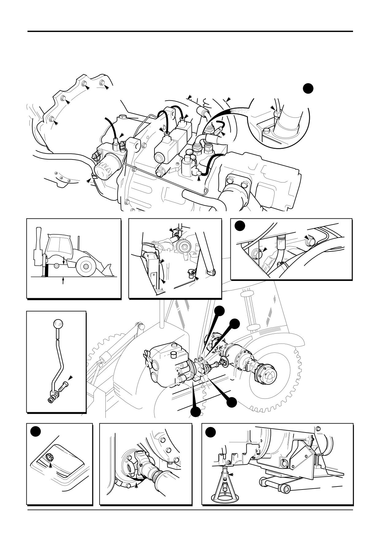
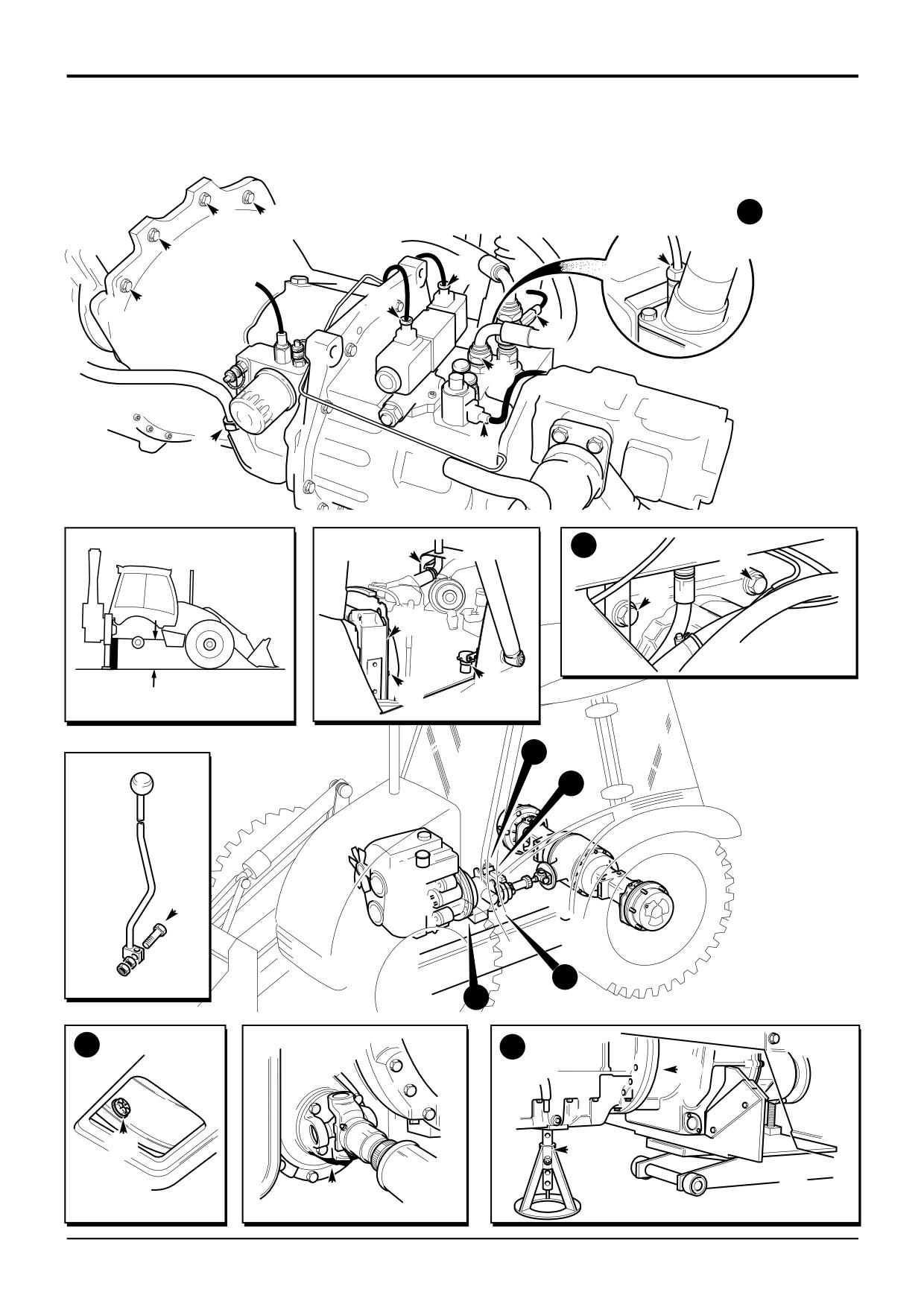
IMPORTANT: The gearbox is heavy. Unless it is safely
11
At a later stage the gearbox and engine assembly is
supported during removal and replacement it could fall and
tilted to allow access to fixing bolts. To prevent damage
cause injury. Make sure that you have access to suitable
as the engine is tilted components must have their
jacks and a gearbox locating ‘cradle’ before attempting to
fixings removed as follows:
remove the gearbox.
a Fuel sediment bowl assembly E (2 bolts).
! WARNING
b Exhaust stack fixing bracket F (2 bolts).
d Radiator fan cowl G (4 bolts).
A raised and badly supported machine can fall on you.
Position the machine on a firm, level surface. Before
It is not necessary to remove these components, only
raising one end ensure the other end is securely
release them from their fixings.
chocked. Do not rely solely on the machine hydraulics or
jacks to support the machine when working under it.
12
Support the gearbox using a suitable trolley jack and
cradle. The gearbox must be securely located on the
Disconnect the battery, to prevent the engine being
cradle as shown at Y.
started while you are beneath the machine.
GEN 1-1
13
Make sure that the weight of the gearbox is supported
by the trolley jack and then remove the gearbox
Removal
mounting bolts H.
1
Park the machine on firm level ground. The gearbox is
14
Using the trolley jack, lower the gearbox and engine to
heavy. If the ground is soft or uneven it will not be
gain access to the top torque converter housing to
possible to remove the gearbox safely.
engine block retaining bolts J. Put a support under the
engine as shown at Z to prevent it from dropping when
2
Loosen the right side rear wheel nuts. Rest the shovel
the gearbox is removed.
on the ground and lower the stabilisers to raise the rear
of the machine. Check dimension X which must be at
15
Undo the four bolts J at the top of the torque converter
least 800 mm. This will allow the gearbox to be pulled
housing. Note that the two outer most bolts have nuts
clear. Block/support the machine.
instead of screwing into the engine block. Also note the
position of the electrical earth straps.
Note: On sideshift machines, suitable lengths of steel
channel can be used as safety struts between the stabiliser
16
Pull off the breather tube K. Undo the gearbox dipstick
feet and chassis, one at each stabiliser.
fixing nut L and then remove the dipstick tube.
3
Remove the right hand side rear wheel.
17
Uncouple the forward/reverse solenoid valve
connectors M, oil pressure sender N and temperature
4
Remove the bonnet
- see Section
3, Routine
sender P (if fitted). Label the connectors for
Maintenance.
identification when refitting.
5
Disconnect the gearshift from the top of the gearbox,
18
Disconnect the gearbox oil cooler hoses R.
as shown at A.
19
On 4 wheel drive machines, uncouple the electrical
6
Remove the rear axle propshaft - see Propshafts.
connector at the 4WD solenoid S.
7
Disconnect the front axle driveshaft bolts B (use tool
20
Remove the flywheel housing to engine bolts T.
892/00822).
21
Manoeuvre the gearbox with the torque convertor clear
8
Drain the hydraulic tank and remove the main hydraulic
of the engine housing.
pump (see Section E, Service Procedures and Main
Hydraulic Pump). Tie the suction hose up clear of the
22
Lower the trolley jack and pull the gearbox and torque
gearbox.
convertor clear of the machine.
9
Drain the gearbox oil, see Section
3, Routine
Maintenance.
10
Remove the access bung/plate at the bottom of the
torque converter housing. Through the access hole,
loosen and remove the torque converter to engine
flywheel retaining bolts D.
9803/3280
Issue 1
Section F
Transmission
Section F
105 - 3
Synchro Shuttle Gearbox
105 - 3
Removal and Replacement (cont’d)
a
J J
K
J
M
M
J
P
N
L
S
b
F
H
H
G
E
G
X
a
b
A
d
c
A401310
c
d
T
D
Z
Y
B
9803/3280
Issue 1
Section F
Transmission
Section F
105 - 4
Synchro Shuttle Gearbox
105 - 4
Removal and Replacement (cont’d)
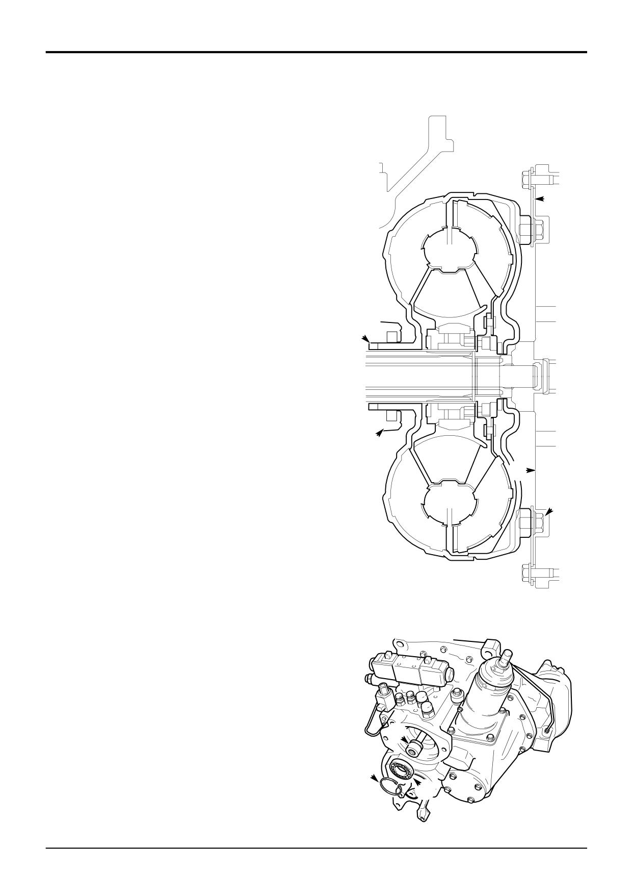
Replacement
Replacement is a reversal of the removal procedure but note
the following:
1
Before replacing the gearbox remove circlip 5 and
withdraw the pump driveshaft 6 together with its
bearing 7 approximately 50 mm (2.0 in). The shaft can
8
then be engaged after the gearbox has been fitted,
making replacing the gearbox easier. Remember to
engage the pump drive shaft, refit the bearing and
circlip after the gearbox has been fitted.
2
Set the torque converter as described in Torque
Converter, Removal and Replacement.
3
Align the Torque Converter
It is vitally important that the torque converter is
1
fitted at the gearbox and engine flywheel correctly.
Failure to locate the converter correctly will result in
damage to the gearbox oil pump on engine start up.
Proceed as follows:
Make sure that the torque converter drive dogs 1 are
correctly engaged with the pump 2 on the gearbox.
Temporarily tie the converter onto the gearbox. Use
wire tied at a drive plate bolt hole to a convenient point
on the outside of the gearbox.
2
Take note of the flywheel and drive plate fixing hole
4
phasing. The heads of the bolts 3 will foul the flywheel 4
if phasing is incorrect.
3
Before bolting the torque converter housing to the
engine make sure the mating faces are fully together
(DO NOT USE FORCE). The drive plate 8 should also
be mated close to the flywheel. Do not force the
components together with the fixing bolts.
Make sure that the torque converter is free to rotate
slightly within the clearance of the location bolt holes. If
A396460
you cannot rotate the converter it is trapped either by
bolt heads 3 or by incorrectly located pump drive dogs.
Make sure that all is well before tightening the bolts.
4
Fill the gearbox with the specified amount and type of
oil (see Section 3, Routine Maintenance). Leave hose
N off until the filling operation is complete. After filling
refit hose N.
Torque Settings
Item
Nm
kgf m lbf ft
6
B
79
8
58
D
44
4.5
32
H
237
24
175
5
J,T
98
10
72
7
A396890
9803/3280
Issue 1
Section F
Transmission
Section F
110 - 1
Synchro Shuttle Gearbox
110 - 1
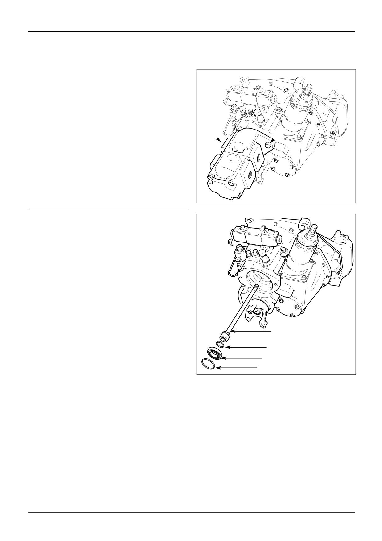
Dismantling
Cleanliness is of the utmost importance when servicing the
gearbox. All precautions to prevent any ingress of dirt, grit
etc. must be taken. To this end wash the exterior of the
gearbox assembly as follows;
Make sure that all open ports and orifices are effectively
plugged. Remove any deposits of dirt, grit and oil from the
outer casings using a suitable degreaser and water. Dry the
casings.
Note: For details of service tools refered to, see Service
A
Tools at the front of this section.
A
Note: If the main hydraulic pump has not been removed,
remove it. Support the pump, undo the 2 fixing bolts A and
then withdraw the pump from the gearbox.
A388030
1
Remove the circlip and then withdraw the pump
driveshaft 1a together with its bearing 1b.
2
Remove and discard the shaft sealing ring.
1a
2
1b
1
A388040
9803/3280
Issue 1
Section F
Transmission
Section F
110 - 2
Synchro Shuttle Gearbox
110 - 2
Dismantling (cont'd)
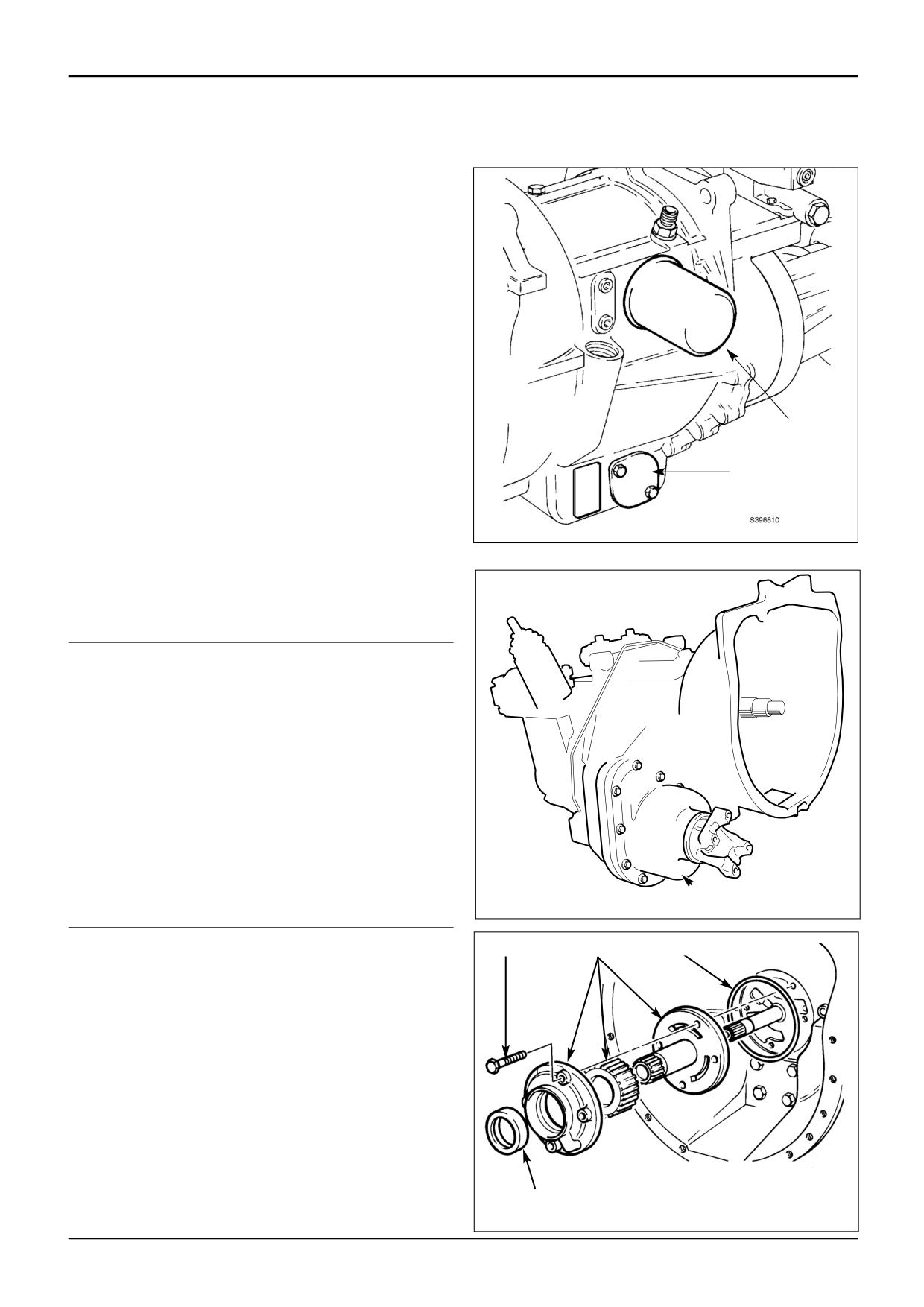
3
Drain the oil from the casing by removing the suction
strainer 3a. Remove and discard the oil filter 3b.
3b
3a
4
If the gearbox is fitted with a 2/4 wheel drive unit B,
remove it. For the correct procedure see Hydraulic 2/4
wheel Drive Unit, Dismantling .
B
A395360
5
Unscrew bolts and withdraw pump.
5
7
6
6
Remove and discard pump sealing ring.
7
Separate pump components. Note that the pump
components are held together with a security screw at
the rear of the assembly.
8
Remove and discard oil seal from pump housing.
8
221021
9803/3280
Issue 1
Section F
Transmission
Section F
110 - 3
Synchro Shuttle Gearbox
110 - 3
Dismantling (cont'd)
Position transmission vertically, standing on the face of the
10a
torque converter housing.
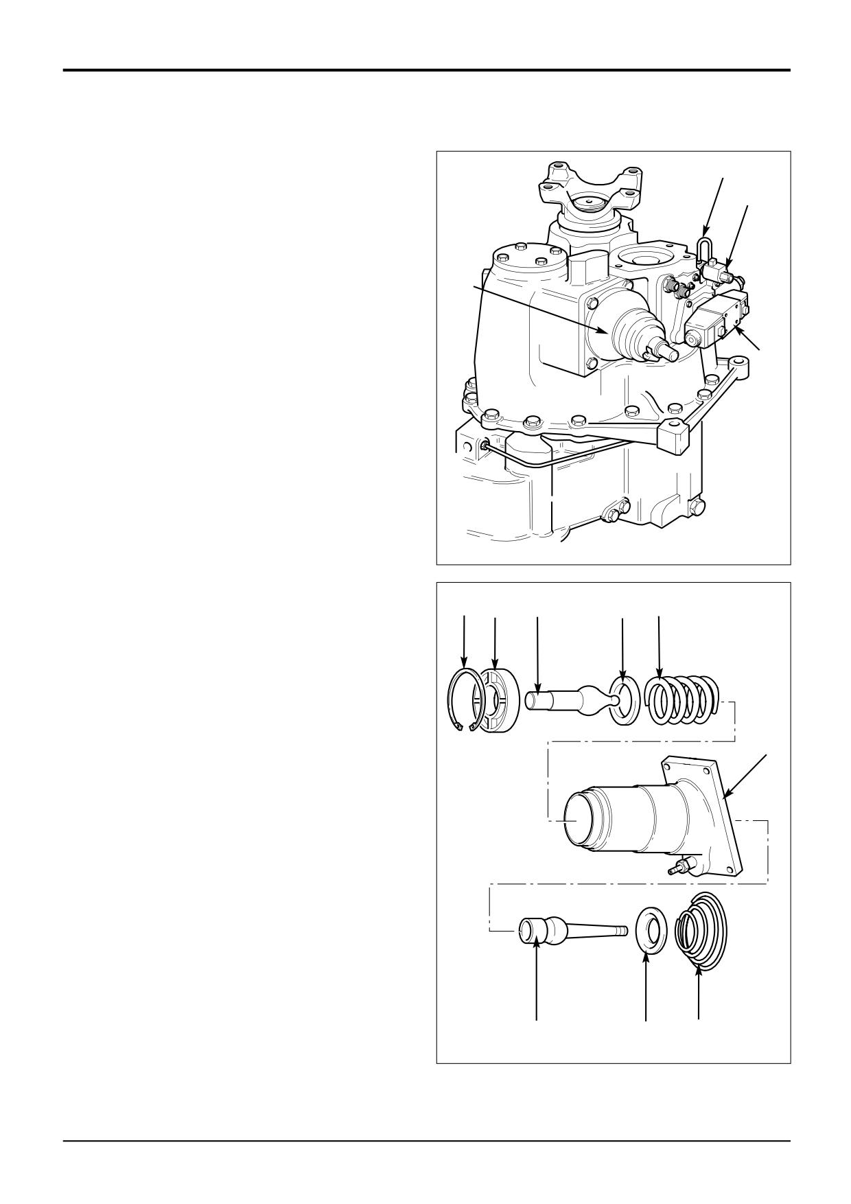
10
9
Unscrew capscrews and remove solenoid control valve.
Note ‘O’ rings fitted around ports on mating face of
solenoid valve body.
Note: See Service Procedures, Forward/Reverse Control
11
Valve for solenoid dismantle/assembly .
10
On 4 wheel drive transmissions remove the 4 wheel
drive hydraulic pipe and control valve 10a.
9
11
Undo the 4 bolts and remove the gear lever turret.
Remove the baffle plate beneath if fitted. If necessary
the turret assembly can be dismantled as follows:
a Slacken worm drive clips and remove rubber boot.
b Using a suitable press or clamp, carefully press the
top lever 11a down to compress spring 11b, just
enough to release pressure on circlip 11c.
Note: BEWARE of spring pressure acting on nylon seat when
circlip is removed.
A387950
c Remove circlip 11c.
11c
11d
11a
11e
11b
d Slowly release the pressure from the top lever 11a
and remove it, together with bush 11d, washer 11e
and spring 11b.
e Rotate spring 11c so as to disengage from the
retaining tabs inside the turret 11. Be aware that the
spring may suddenly disengage while still under
pressure. Repeat this operation until all the coils are
disengaged and the spring can be removed.
11
f
Remove retainer 11f and bottom lever 11g.
A388210
11g
11f
11c
9803/3280
Issue 1
Section F
Transmission
Section F
110 - 4
Synchro Shuttle Gearbox
110 - 4
Dismantling (cont'd)
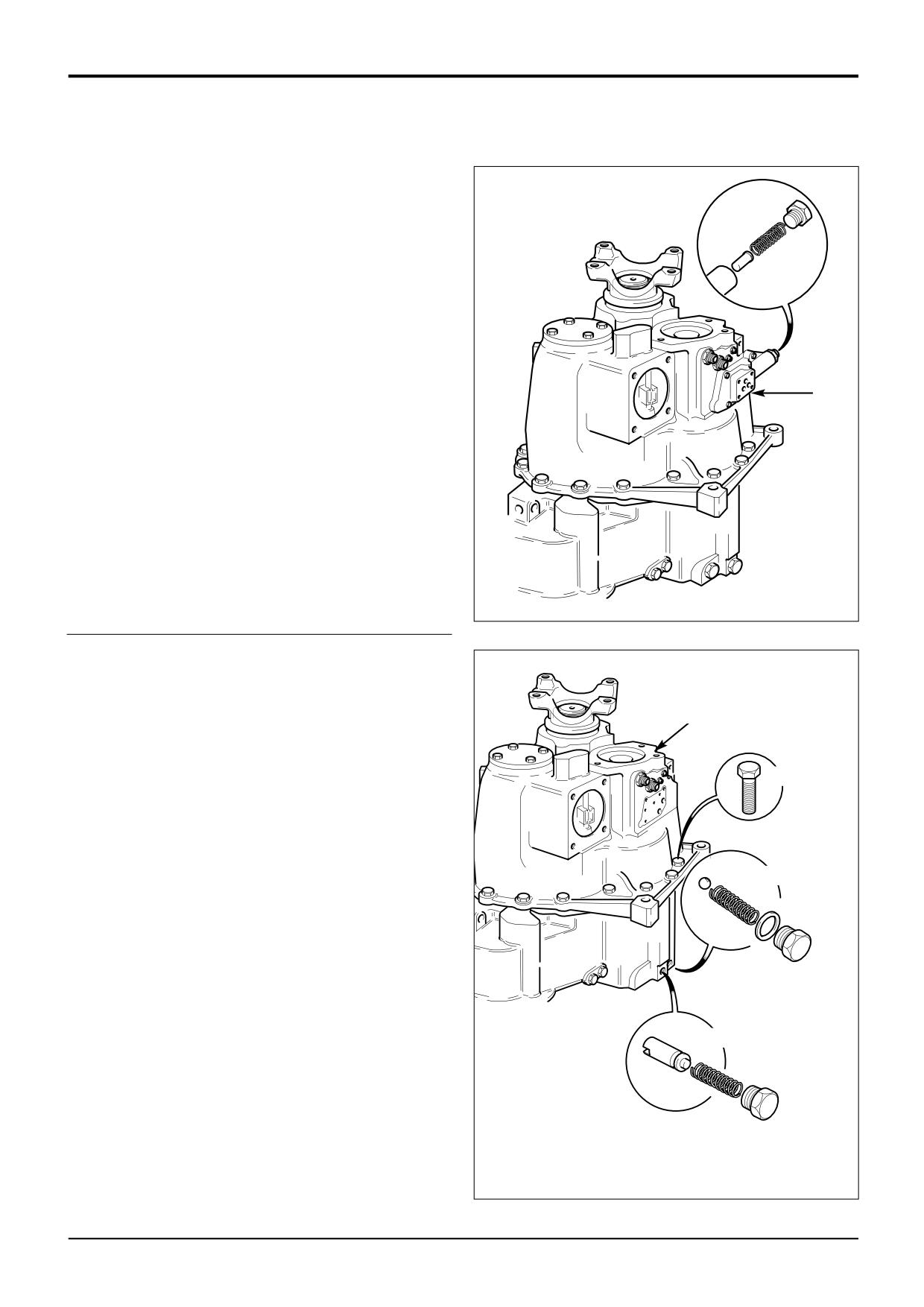
12
Unscrew plug and withdraw pressure maintenance
valve spool and spring.
12
13
Unscrew four bolts and remove pressure maintenance
valve body. Remove and discard gasket.
13
A387960
14
Remove the torque converter pressure relief valve ball
and spring assembly 14a. Remove the torque converter
pressure regulating valve spool and spring assembly
14b.
15a
15
Unscrew bolts and lift off output end casing 15a. Be
sure to retrieve bearing outer cups from inside the
casing. Keep the cups together with their associated
15
bearing.
14a
14b
A387970
9803/3280
Issue 1
Section F
Transmission
Section F
110 - 5
Synchro Shuttle Gearbox
110 - 5
Dismantling (cont'd)
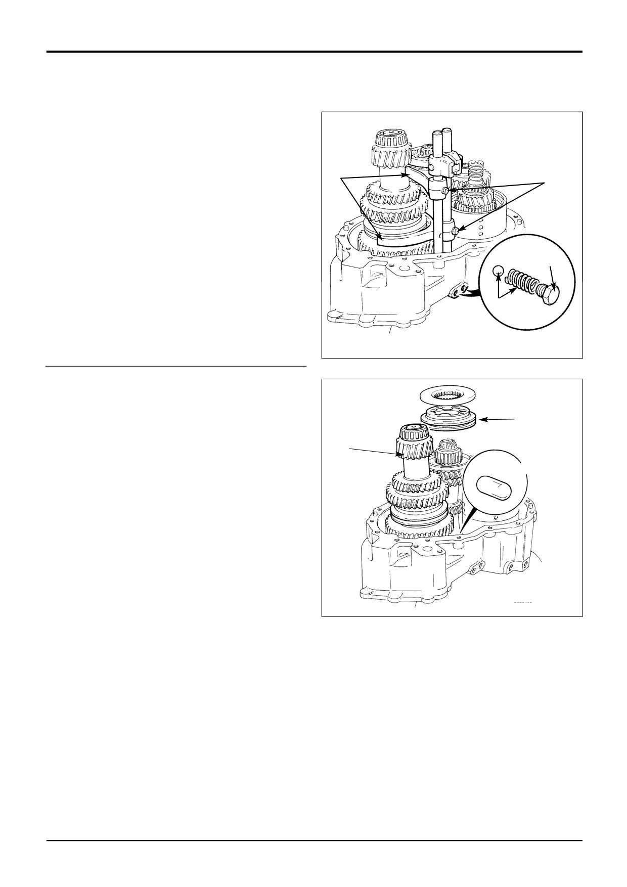
16
Unscrew selector detent plugs.
17
Remove selector detent balls and springs.
18
Unscrew selector fork retaining screws and lift out
selector rods.
19
18
19
Note that the selector forks are not interchangeable.
Mark the forks to ensure they are replaced correctly.
Remove selector forks.
16
17
221080
20
Push out the interlock plunger on disassembly.
21
Lift off 3rd/4th synchro-hub. Note the positions for
refitting with mating cups.
21
22
Lift out layshaft assembly .
22
20
S395460
9803/3280
Issue 1
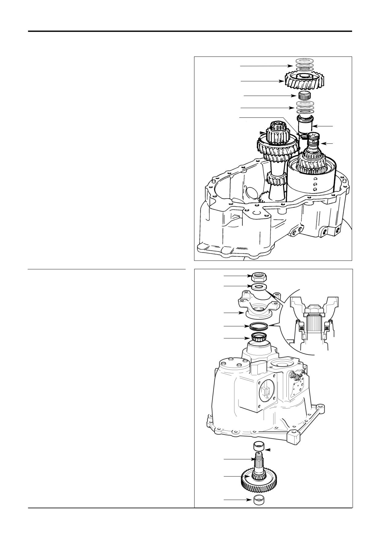
Section F
Transmission
Section F
110 - 6
Synchro Shuttle Gearbox
110 - 6
Dismantling (cont'd)
23
23
Remove idler gear upper thrust washers and bearing.
Keep the thrust washers and bearing together.
24
24
Tilt mainshaft L to one side and lift off idler gear
24a
together with its needle roller bearing 24a.
25
25
Remove idler gear lower thrust washers and bearing.
Keep the thrust washers and bearing together.
29
26
26
Lift off idler gear spacer.
L
27
27
Tilt mainshaft L to one side and lift out the
forward/reverse assembly. Discard sealing rings.
Note: See 2/4 Wheel Drive Clutch for forward/reverse unit
dismantling and assembly procedures.
28
Remove mainshaft L.
29
The idler gear spindle is a press fit in the casing. Use a
*
suitable puller screwed into the 1/2in. B.S.P. hole in the
end of the spindle for extraction. Note that the spindle
should only be removed if it is damaged and is required
to be replaced.
S407370
30
30
Unstake the nut. Whilst holding the output yoke with
service tool 892/00812, unscrew output shaft nut and
30a
remove the washer 30a beneath. Support output
shaft from beneath and lift off the yoke 30b.
31
Withdraw output shaft assembly and lift out outer
30b
bearing 31a. Remove spacer N and retain for assembly.
32
32
Prise out oil seal and discard.
31a
33
Using a suitable puller, withdraw output shaft inner
bearing. Remove the mainshaft bearing outer cup 33a
from the centre of the output shaft transfer gear.
N
31
33
33a
A388000
9803/3280
Issue 2*
Section F
Transmission
Section F
110 - 7
Synchro Shuttle Gearbox
110 - 7
Dismantling (cont'd)
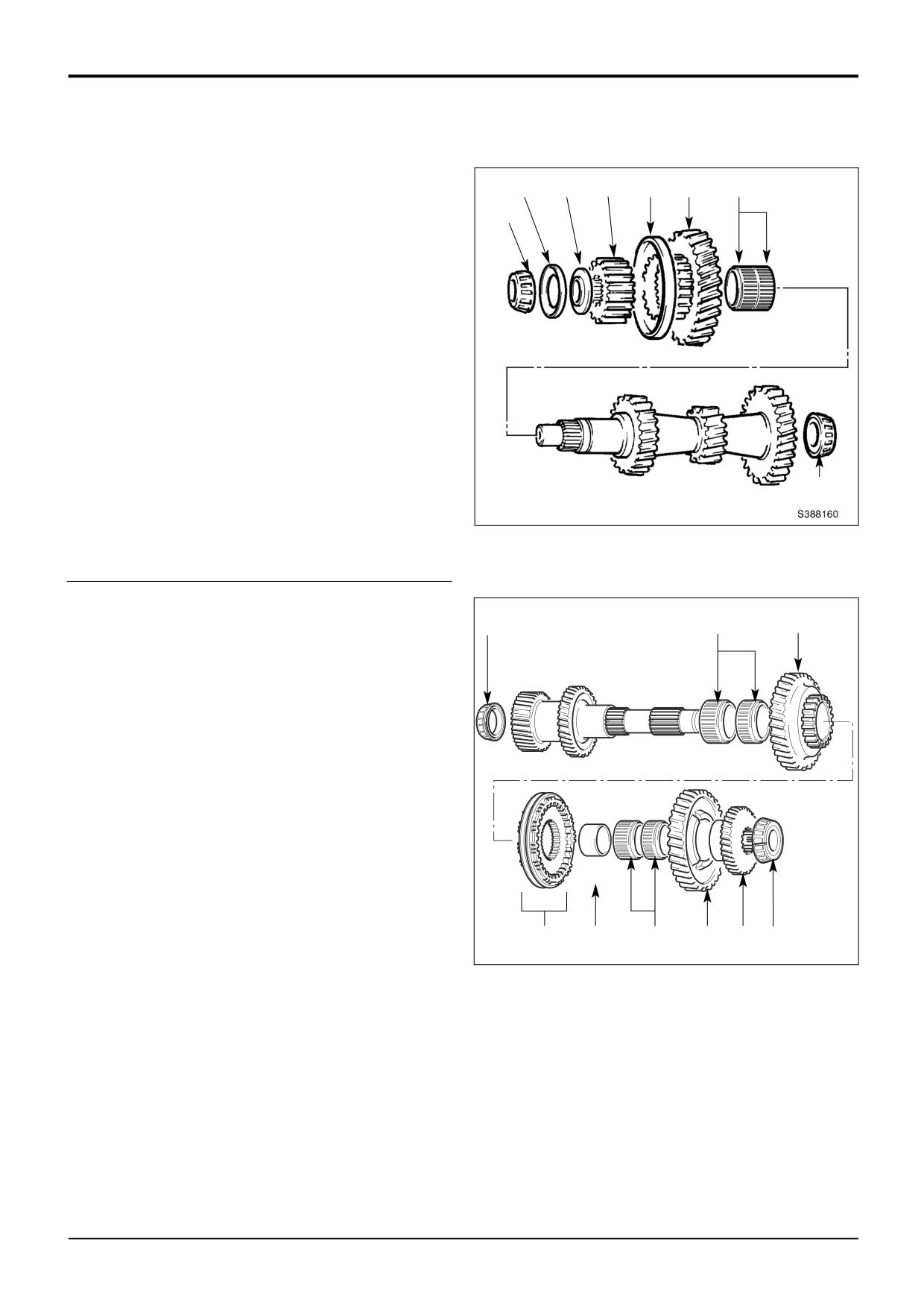
Mainshaft
34d
34c
34b
34a
34d
35
34
Using service tool 892/00179 and adapter 992/06300
34e
pull off 3rd gear together with synchro cup 34a, gear
34b, spacer washer 34c, oil retention washer 34d and
bearing 34e. Keep the synchro hubs and cups in their
original relationship.
35
Remove needle roller bearings 35.
36
Remove bearing from converter end of mainshaft using
press 892/00179.
36
Layshaft
37
42
41a
37
Remove the bearing 37. Remove 4WD transfer gear 37b
and bearing 37a from layshaft. On 2WD machines a
spacer is fitted in place of the transfer gear.
38
Lift off 1st gear.
39
Remove 1st gear needle roller bearings.
40
Note that the 1st/2nd synchro unit 40 is of a different
design to the 3rd/4th gear unit. There are components
which may be lost during removal unless care is taken.
Hold the unit together with the synchro cones on each
side and lift off. Keep the synchro cones, rings and
hubs in their original relationship.
*
41
Use a press to push off 2nd gear 41a, synchro
assembly 40 and 1st gear needle roller track ring 41b.
A395470
40
41b
39
38 37b 37a
42
Remove 2nd gear needle roller bearings.
9803/3280
Issue 2*
Section F
Transmission
Section F
110 - 8
Synchro Shuttle Gearbox
110 - 8
Dismantling (cont'd)
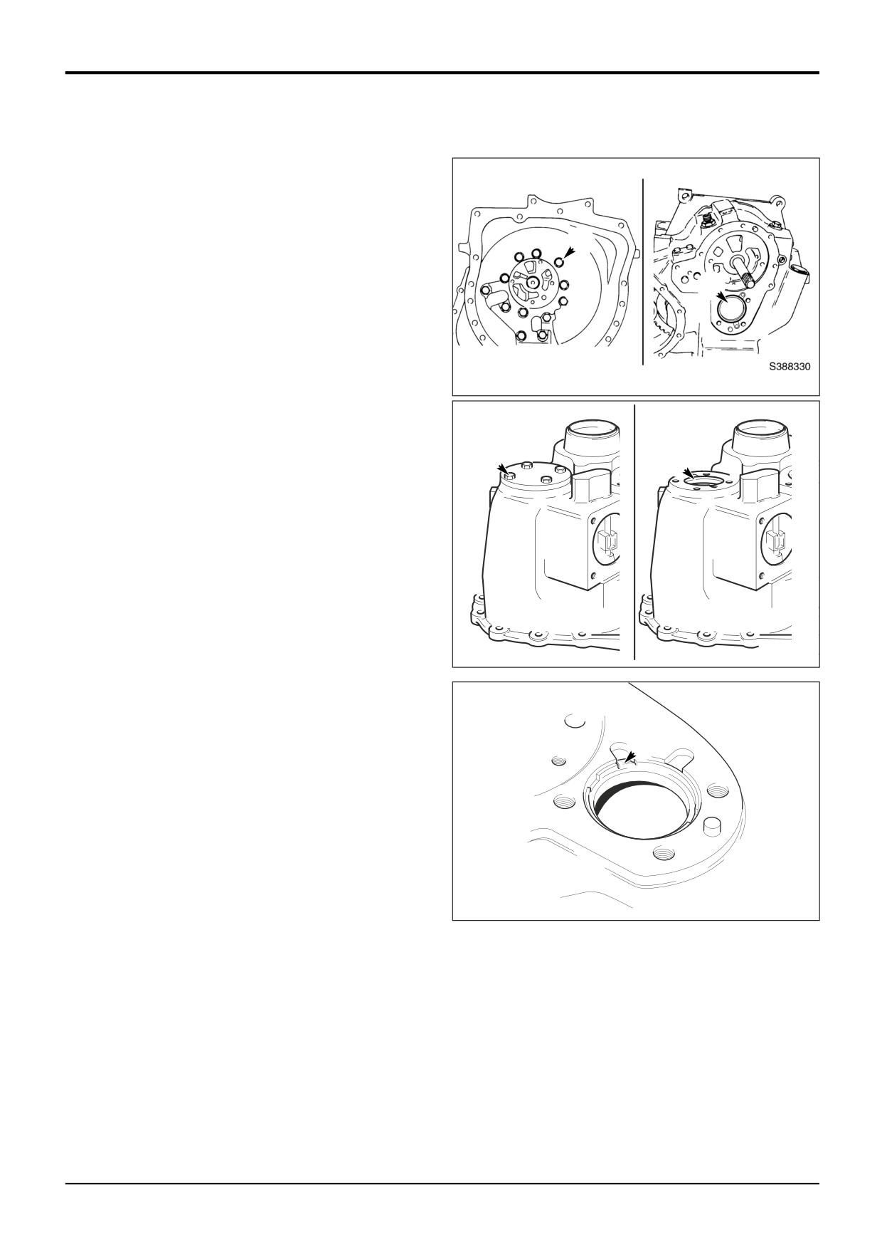
Setting Ring Removal
The mainshaft and layshaft end float is controlled by a
threaded ‘setting ring’ screwed into the casing.
To enable access to the mainshaft setting ring the torque
X
converter housing must be removed. Undo the 12 fixing
bolts X and remove the housing. The setting ring is located
at position B.
B
To enable access to the layshaft setting ring the bearing
cover must be removed. Undo the 4 fixing bolts Y, remove
the cover and discard the gasket beneath. The setting ring is
located at position C.
388330
If the bearings or shaft are to be renewed the associated
setting ring must be removed and discarded as follows:
1
Carefully prise out the staked section of the ring Z clear
Y
of the casing.
C
2
Using the special socket adaptor, unscrew and discard
the ring. (Use adaptor 892/01080 for the layshaft ring
and 892/01079 for the mainshaft.)
3
Be sure to remove any shards of metal that may have
fallen into the casing.
Note: Once removed, the setting rings must not be re-used.
Discard the ring and obtain a new one. Note that the
mainshaft and layshaft setting rings are not interchangeable.
A388320
Z
A388230
9803/3280
Issue 1
Section F
Transmission
Section F
111 - 1
Synchro Shuttle Gearbox
111 - 1
G
A1
A2
C
X
B2
B1
Y
9803/3280
Issue 1
Section F
Transmission
Section F
111 - 2
Synchro Shuttle Gearbox
111 - 2
Inspection
Before assembling the gearbox make sure that a thorough
inspection of all components is carried out. Remember that
although a failed component may be easy to identify, the
cause of that failure may be less easy to trace. It is also
possible that a failed component may have caused damage
to other areas of the gearbox.
1
Carefully remove all traces of gasket compound from
components as follows:
a Front and rear casing mating faces.
b Front casing and torque converter housing mating
faces.
2
Clean the inside of the casings using a suitable
degreasing agent.
3
Carefully inspect all gears, bearing and shafts for signs
of excessive wear or damage. If wear or damage is
evident, components must be renewed.
4
Make sure that all oil way cross drillings in the casings,
shafts and gears are clear and free from debris. Blocked
oil ways are a common cause of bearing failure. Use an
air line to blow through cross drillings.
Note: If failure of the forward/reverse or 4 wheel drive clutch
is suspected see the relevant dismantling and assembly
procedure in this section.
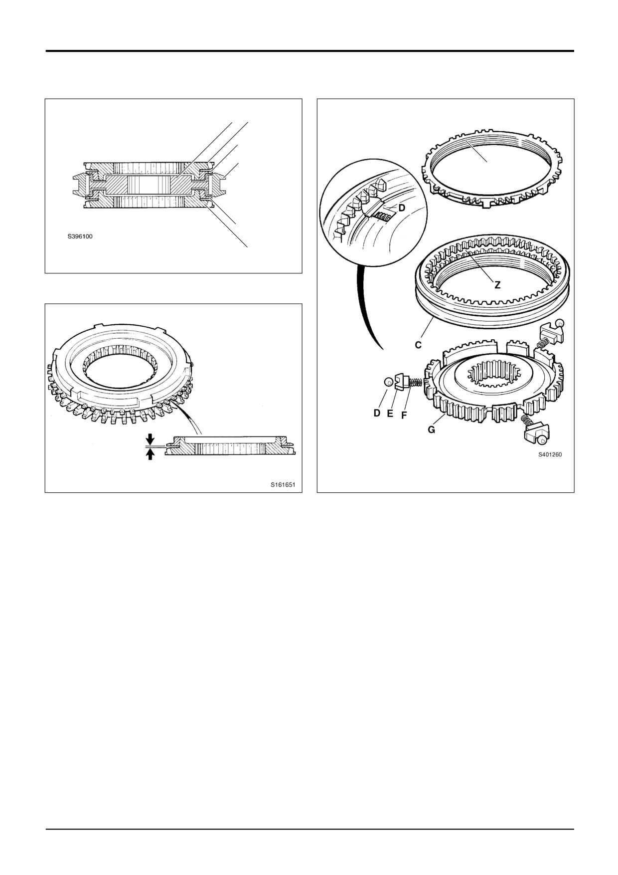
1st/2nd Gear Synchromesh Unit
The 1st/2nd gear synchro unit must be checked for wear
before assembly as follows:
1
Before dismantling the unit be aware that on re-
assembly, the components must be kept in their original
relationships.
2
Dismantle the unit by removing the cones and rings A1,
A2 and B1, B2. Push off the sleeve C taking care to
retrieve the sets of balls D, poppets E and springs F.
3
Inspect the mating faces of cones and rings. The wear
indicator grooves X must still be visible. As a further
check, locate the cones and rings together (as shown at
Y) and measure the clearance between them using
feeler gauges. The clearance should be between 0.5
and 1.9 mm for both A and B pairs. If either is out side
these limits then the complete synchro unit must be
renewed.
4
Inspect the teeth on all cones and rings for excessive
wear or damage. If wear or damage is evident the unit
must be renewed.
9803/3280
Issue 1
Section F
Transmission
Section F
112 - 1
Synchro Shuttle Gearbox
112 - 1
Assembly
Bearing Setting Rings
If the bearing outer cups and setting rings have been
removed, fit new rings so that they are flush with the outer
face of case as shown at A. Press in the outer bearing cups
A
from the inside of the casing as shown at B. Push in the cup
until it is up against the setting ring.
A388250
B
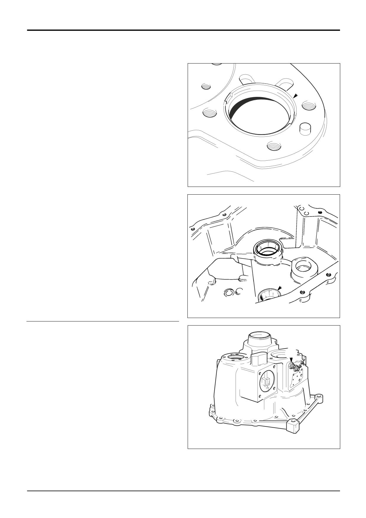
S407550
Casings
If the gearbox casings are to be renewed, be sure to fit
blanking plugs and adapters as required. Inspect the original
casings and identify the blanking plug and adapter positions.
C
Transfer the plugs and adapters to the new casings. Apply
JCB Threadlocker and Sealer to the threads.
Note that new plugs may be supplied with a sealant ‘patch’,
in which case sealant need not be applied. Torque tighten
plugs to 25 - 28 Nm (18.4 - 20 lbf ft).
Before fitting adapter C, be sure to fit the orifice restrictor
inside the port.
A388420
9803/3280
Issue 3*
Section F
Transmission
Section F
112 - 2
Synchro Shuttle Gearbox
112 - 2
Gearbox - Assembly (cont’d)
If the torque converter housing has been removed,
temporarily replace it. The gearbox can again be positioned
standing on the face of the housing ready for assembly.
5b
1a
1b
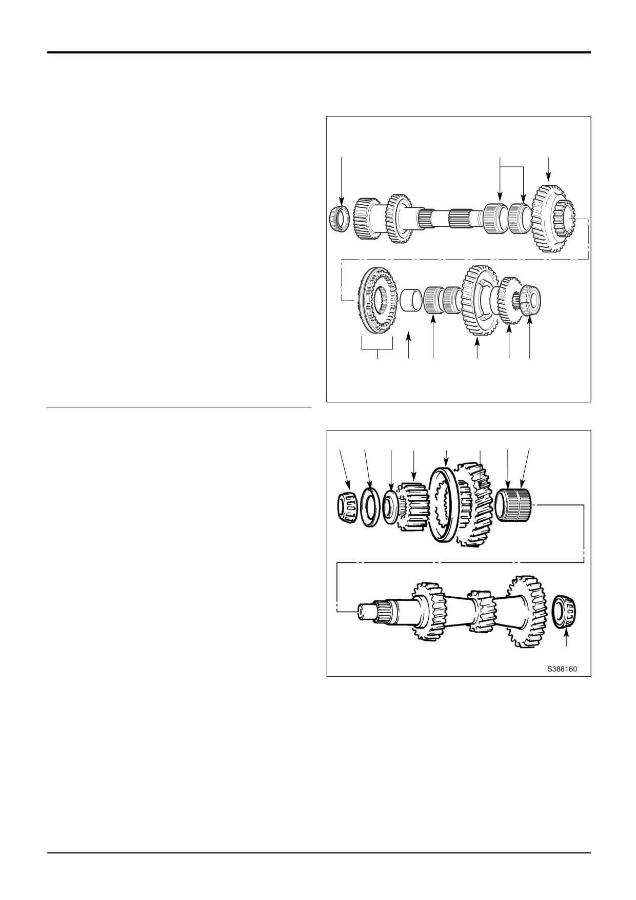
Layshaft Assembly
1
Smear bearing surface of shaft with JCB HP Grease
and fit needle roller bearings 1a (wider bearing first),
followed by 2nd gear 1b.
2
Fit the synchro assembly 2, then press fit the bearing
*
track 3a.
3
Slide 1st gear needle roller bearings 3b over the track.
Smear bearings with oil. Fit 1st gear 3c over needle
roller bearings.
4
Assemble 4WD transfer gear 4 over splines. On 2WD
*
machines slide spacer over splines.
5
Press bearing 5a and 5b onto the assembled layshaft.
A395470
Smear the bearings with JCB HP Grease.
2
3a 3b
3c
4
5a
Mainshaft Assembly
7c 7b 7a 6e
6d
6c 6b 6a
6
Smear bearing surface of mainshaft with JCB HP
Grease. Fit the needle roller bearings 6a and 6b.
Assemble 3rd gear 6c and synchro-cup 6d. Fit synchro
gear 6e.
7
Fit spacer washer 7a and oil retention washer 7b. Note
the correct way round of components 7a and 7b. Press
bearing 7c onto shaft and smear with JCB HP Grease.
8
Press bearing onto assembled mainshaft and smear
bearing with JCB HP Grease.
8
9803/3280
Issue 2*