JCB 3CX, 4CX, 214e, 214, 215, 217 & VARIANTS Backhoe Loader. Service Manual - page 27
Section F
Transmission
Section F
82 - 5
Front Axle - SD55
82 - 5
Drive Head - Assembly (cont’d)
9803/3280
Issue 1
Section F
Transmission
Section F
82 - 6
Front Axle - SD55
82 - 6
Drive Head - Assembly (cont’d)
9
To select the right size spacer 24, subtract the end float
16
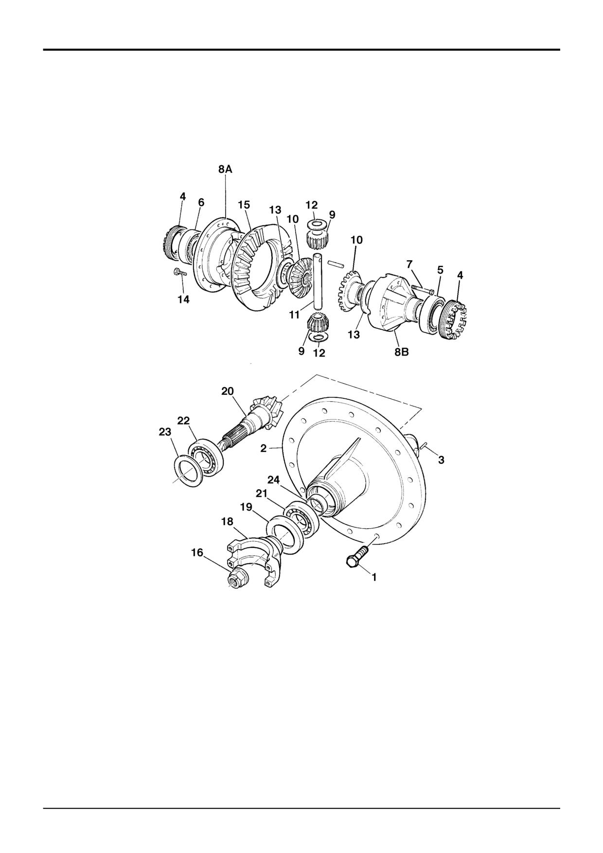
Assemble the trunnion pin 11, bevel gears 9 and 10 and
obtained at step 7 from the solid spacer size (14.20
their thrust washers 12 and 13 into differential half case
mm). Also subtract 0.04 mm to allow for theoretical
8A.
bearing tolerance and pre load. The result is the size of
spacer to be fitted from the solid spacer setting kit. If
17
Position differential half case 8B onto half case 8A,
there is no spacer of this size, fit the next nearest size
aligning the match-mark letters. Apply JCB
spacer, refer to Service Tools - Axles.
Threadlocker and Sealer to the threads of bolts 7, then
Example
fit and torque tighten to 46 Nm (34 lbf ft, 4.7 kgf m).
Temporary spacer size
14.20
Check the gears for free rotation.
Subtract end-float
0.25
18
Fit crownwheel 15 using new Verbus Ripp bolts 14
Total
13.95
tightened to 94 Nm (69 lbf ft, 9.59 kgf m).
Subtract tolerance & preload
0.04
Result
13.91
19
Locate crownwheel assembly (without bearings) into
(No spacer available this size, use next nearest size
housing.
spacer i.e 13.900)
20
Drive bearing cones 5 and 6 onto differential case
spigots. Lightly oil the bearings then fit their bearing
10
Remove sleeve B and temporary spacer. fit correct size
cups and castellated nuts 4 into drive head carrier 2.
spacer from solid spacer setting kit, refer to Service
Do not fit the roll pins 3 at this stage.
Tools - Axles. During removal take care to avoid
damaging the outer bearing.
21
Adjust castellated nuts 4 to give an increase in input
pinion rolling torque of between 1.36 - 2.5 Nm (12 - 22
11
Fit sleeve B. Tighten adapter C to no more than 50 Nm
lbf in) more than that recorded in Step 13.
to protect against bearing damage while spacer
selection is verified making sure the pinion is free to
22
Measure the backlash between crownwheel 15 and
rotate. Check there is no end float and pinion is free to
pinion 20, which should be 0.17 - 0.28 mm (0.006 -
turn smoothly by hand. Remove adapter C and fit nut
0.010 in). Adjust castellated nuts 4 by equal amounts
16. Then check that rolling torque is less than 2.0 Nm. If
when altering backlash. When backlash and preload
the rolling torque exceeds 2.0 Nm, check that the shaft
are both correct, fit roll pins 3.
has been assembled correctly.
23
Check tooth marking to verify crownwheel and pinion
are set correctly, refer to Crownwheel and Pinion
Note: If the pinion is not free to rotate check the correct size
Meshing.
spacer has been fitted.
24
Apply JCB Multigasket to the mating faces of drive
12
If rolling torque measured at step 10 is too high, fit the
head carrier 2 and the axle casing. Fit the drive head
next larger size spacer. If rolling torque is too low, fit
carrier to the axle casing with the crownwheel towards
the next smallest size spacer. If a correct spacer is not
the short drive shaft. Fit securing bolts 1 and tighten to
available from the range, check that drive head is
98 Nm (72 lbf ft, 10 kgf m).
assembled correctly.
25
Reassemble both driveshafts and hub assemblies, refer
to Axle Hub and Driveshaft - Dismantling and
13
Remove adapter C and sleeve B. Fit new oil seal 19,
Assembly.
grease between seal lips before fitting. Fit coupling
yoke 18 and NEW stake nut 16.
26
Re-fill the hubs and differential with the correct grade of
oil, refer to Section 3 Lubricants and Capacities.
14
Progressively torque tighten stake nut 16, occasionally
rotating coupling yoke, up to 250 Nm. Providing the
27
Refit the propshaft, refer to Propshafts - Removing
correct size spacer has been selected the rolling torque
and Replacing.
should be between 2.3 and 3.4 Nm including seal drag.
Note: The nut tightening torque can be increased to a
maximum of 300 Nm provided that the pinion rolling torque
does not exceed the maximum of 3.4 Nm.
15 Finally stake the nut 16 into the slot.
9803/3280
Issue 1
Section F
Transmission
Section F
82 - 7
Front Axle - SD55
82 - 7
Pinion Depth Setting
1
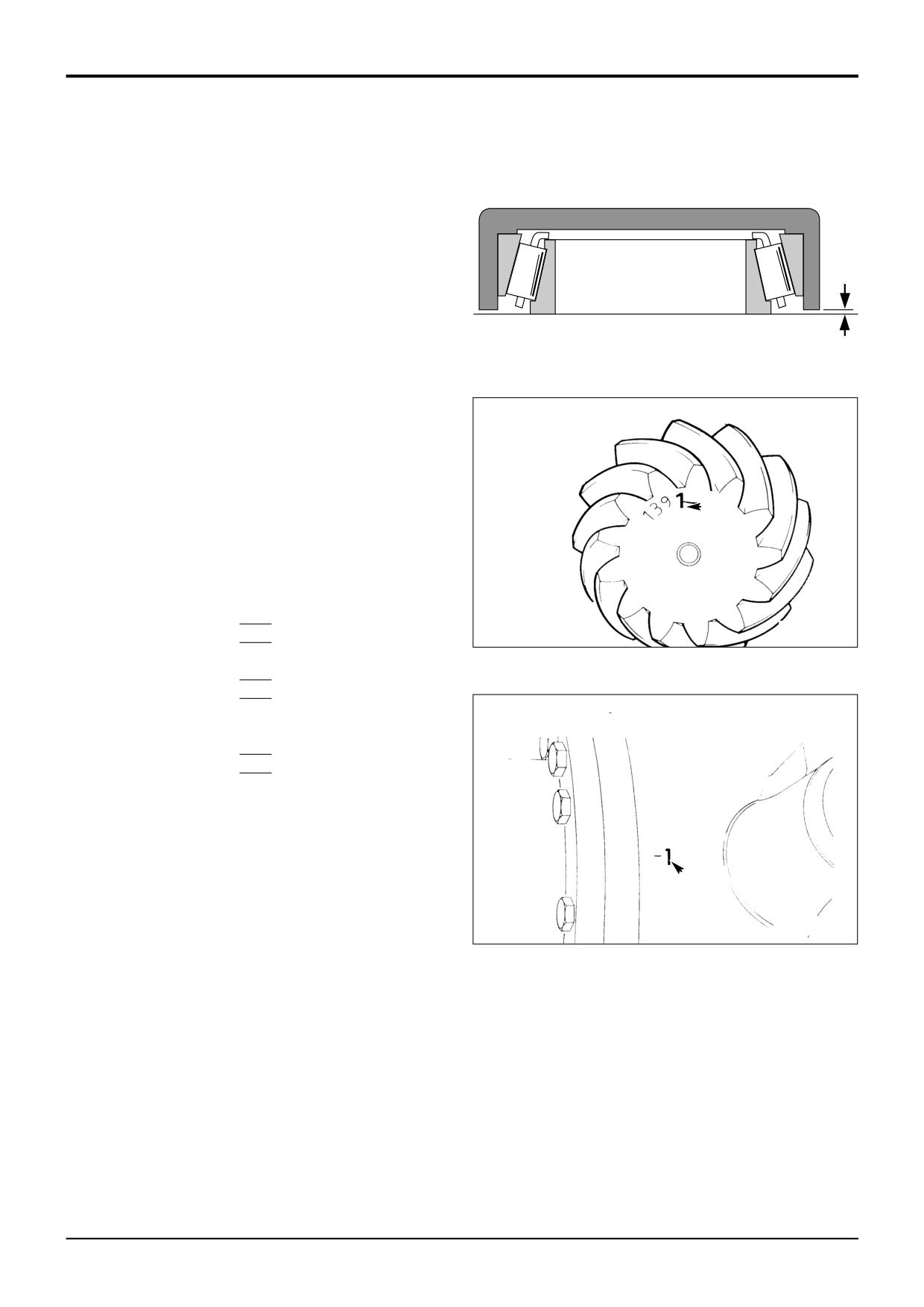
Place new pinion head inner bearing assembly on a flat
surface and position service tool 892/00174 over the
bearing. Measure gap A (e.g. 0.20 mm) and add this to
the cup depth stamped on the tool (e.g. 30.01 mm) to
obtain the bearing depth.
A
2
From the face of the pinion, obtain the etched deviation
figure B (e.g. + 2) which is in units of 0.01 mm. If
positive, add this to the bearing depth; if negative,
subtract from the bearing depth.
A184400
3
Obtain the deviation figure C (e.g. - 1) stamped on the
differential housing bolt flange. If negative, add to
bearing depth; if positive, subtract from bearing depth.
4
Subtract the total of the above figures from the
standard value of 31.19 mm. The result will be the
thickness of shims required behind the pinion head
B
bearing cup.
Example (all dimensions in millimetres)
Cup depth
30.01
Gap A
+0.20
S256110
Bearing depth
30.21
Pinion deviation B (+ 2)
+0.02
Housing deviation C (- 1)
+0.01
Total
30.24
Standard value
31.19
Less Total above
30.24
Shim Thickness
0.95
Note: In the event that the setting data stamp has been
ommited from the drivehead casing, adopt the following
setting procedure:
C
Revise the shim pack size by the difference in setting height
marked on the old and new crownwheel pinion sets.
S256120
9803/3280
Issue 1
Section F
Transmission
Section F
82 - 8
Front Axle - SD55
82 - 8
Crownwheel and Pinion Meshing
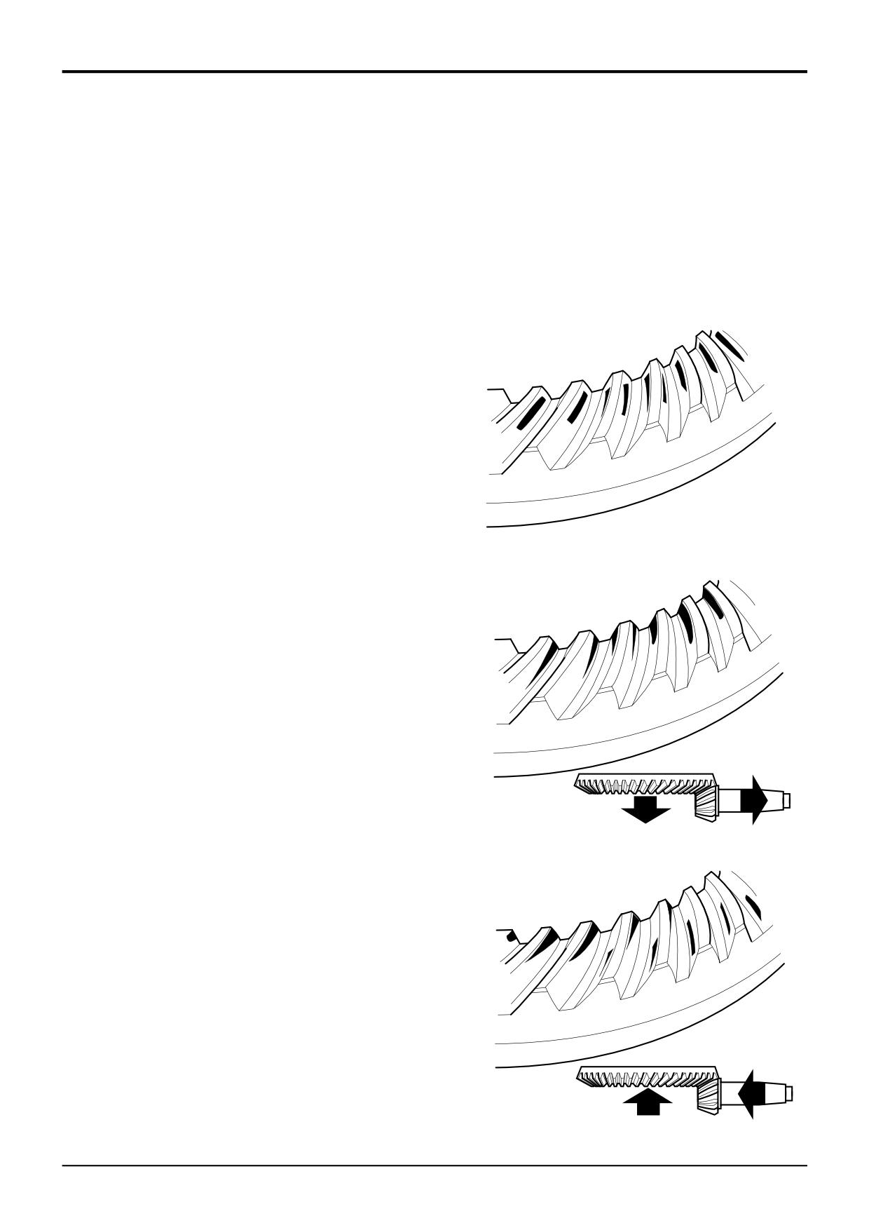
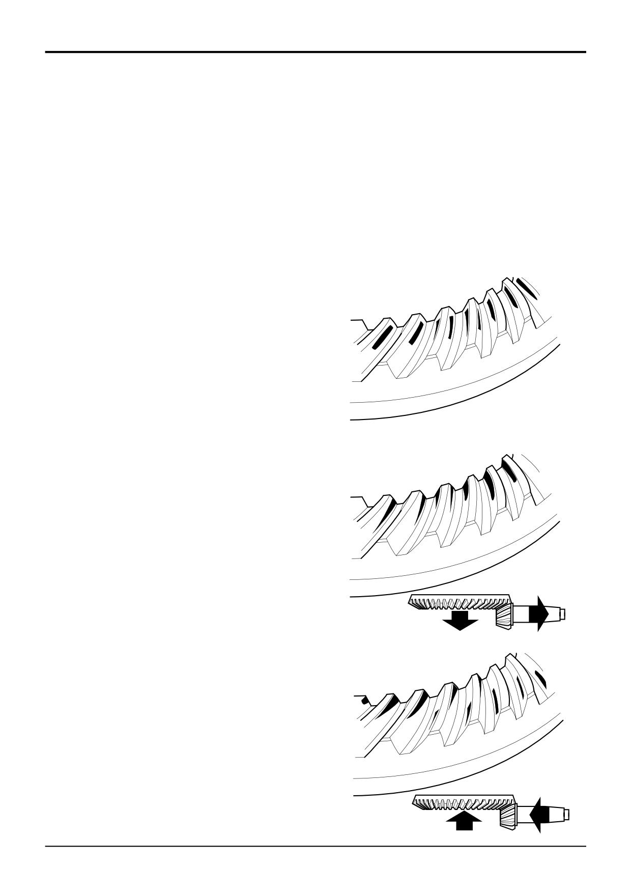
Meshing of the gears should be checked by marking three of
the pinion teeth with engineers marking compound and
rotating the pinion.
The marking will then be transferred to the crown wheel
teeth.
Correct tooth marking.
A386940
Pinion too deeply in mesh.
Decrease the shim thickness between the pinion inner
bearing cup and the axle casing. Move the crown wheel
towards the pinion to correct the backlash.
A386950
Pinion too far out of mesh.
Increase the shim thickness between the pinion inner
bearing cup and the axle casing. Move the crown wheel
away from the pinion to correct the backlash.
A386960
9803/3280
Issue 1
Section F
Transmission
Section F
83 - 1
Front Axle - SD70
83 - 1
S161871
9803/3280
Issue 1
Section F
Transmission
Section F
83 - 2
Front Axle - SD70
83 - 2
Drivehead, SD70 - Dismantling
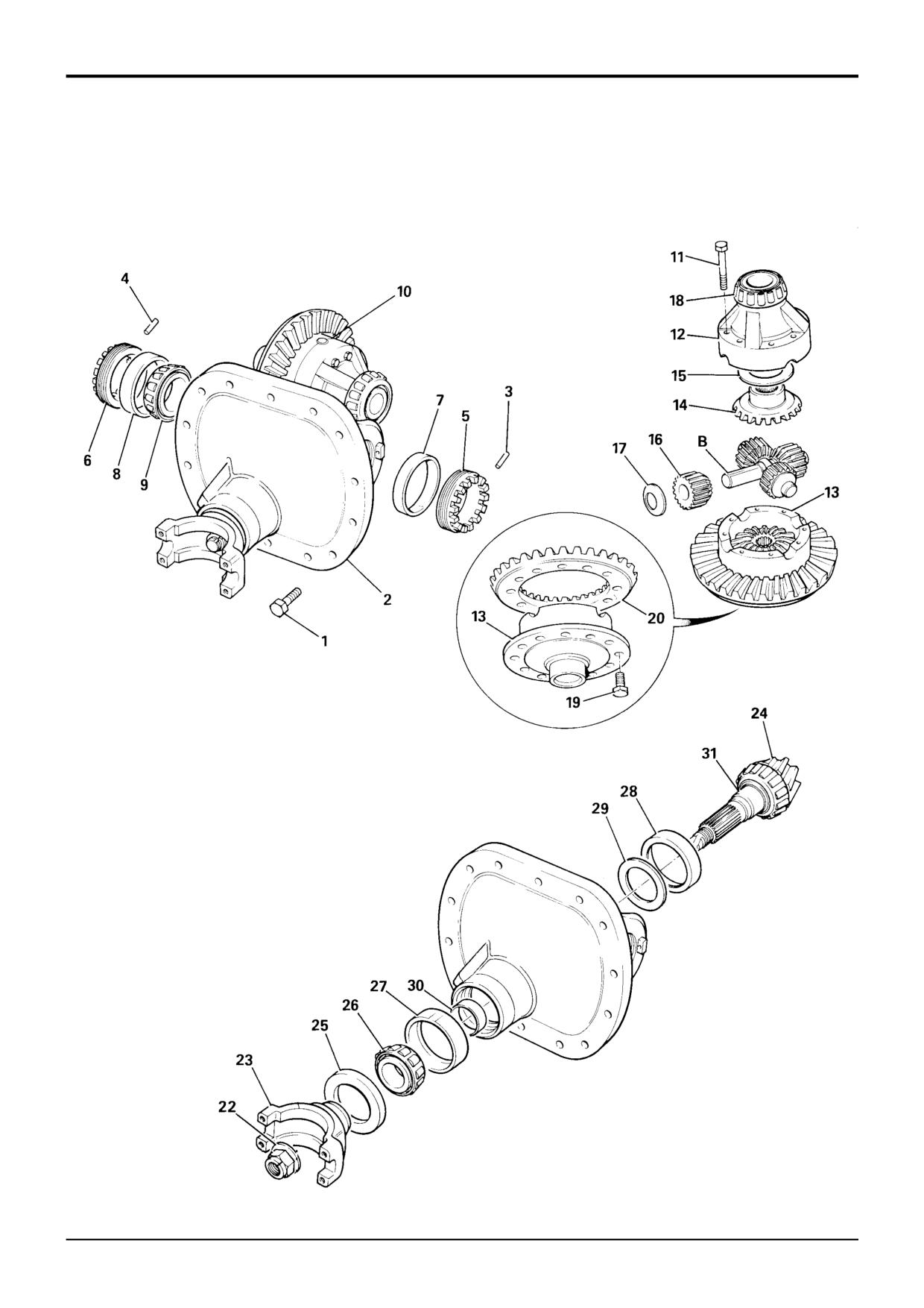
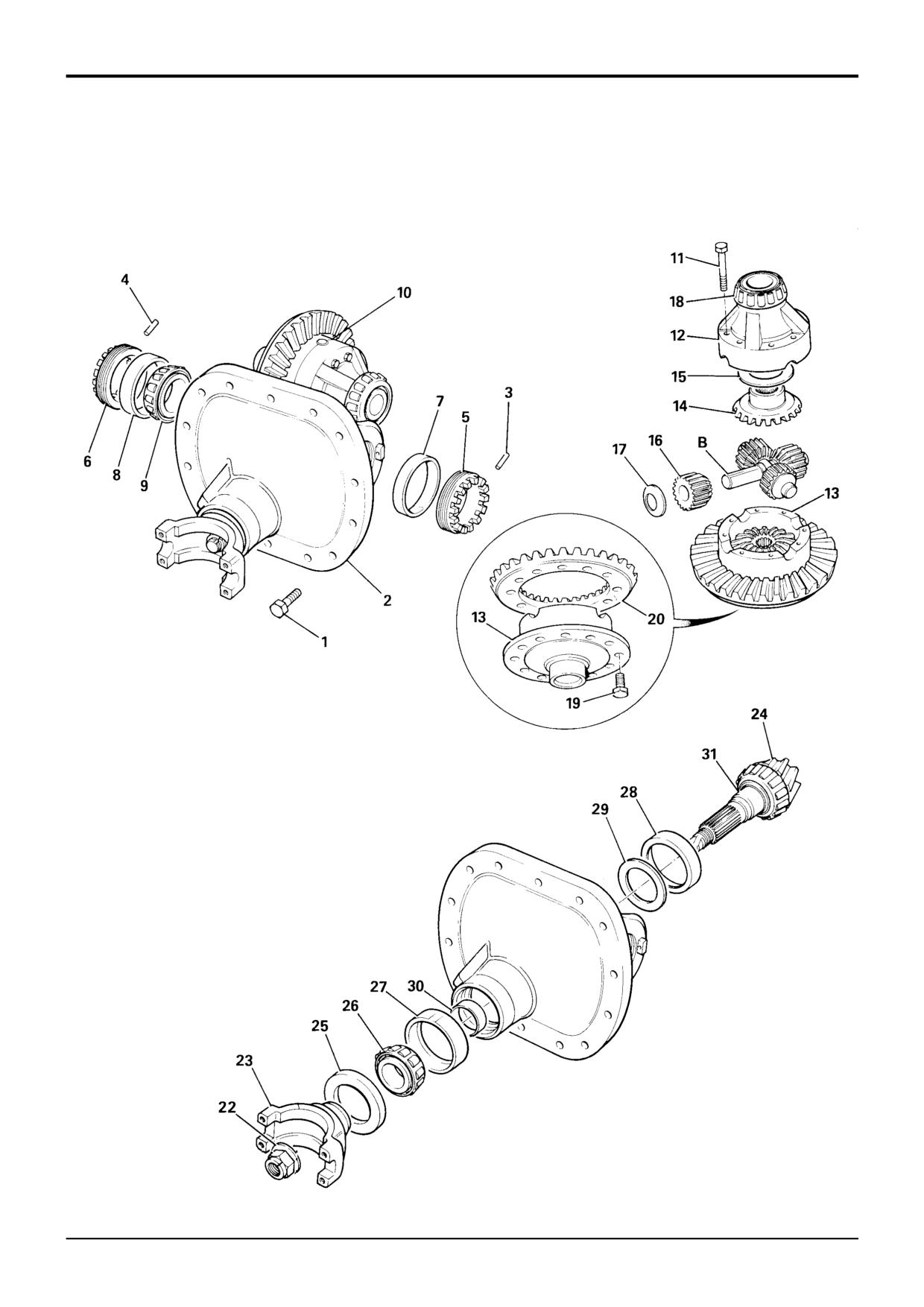
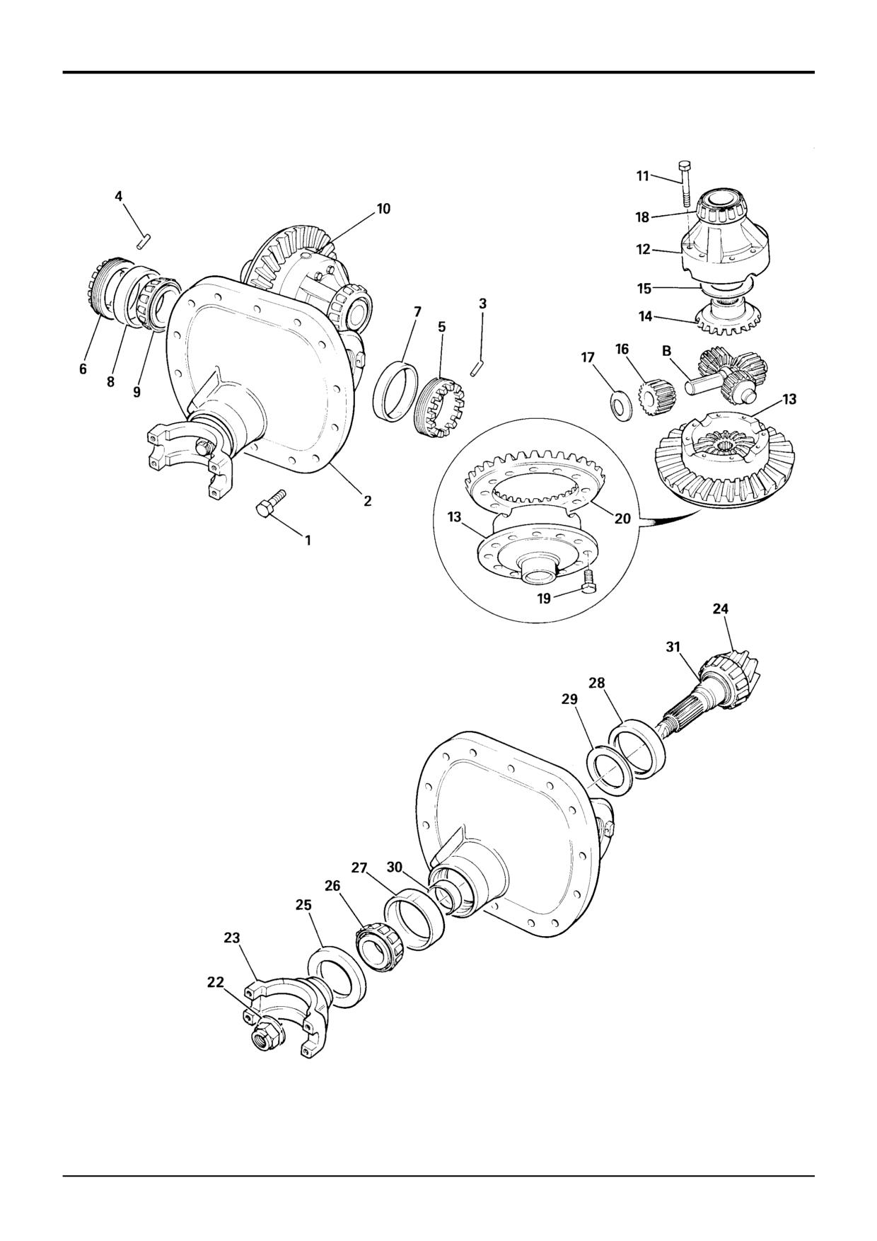
The numerical sequence shown on the illustration is
intended as a guide to dismantling.
For assembly the sequence should be reversed.
1
Drain the oil from the axle centre casing. Remove the
propshaft from the gearbox to the front axle.
2
Remove both hub assemblies complete with
driveshafts (see Hub and Driveshaft Dismantling).
3
Mark the installation position of the drive head carrier,
item 2.
4
Remove the drive head carrier retaining bolts, item 1,
and remove the drive head carrier 2 from the axle
casing.
5
Clean the drive head carrier and axle casing mating
faces.
6
Pull out tension pins 3 and 4, and remove castellated
nuts 5 and 6.
7
Remove bearing outer races 7 and 8.
8
Drive off the taper roller bearing cone 9 from the
crownwheel differential case half.
9
Remove the differential assembly 10 from the carrier.
10
Remove the differential assembly retaining bolts 11 and
separate case halves 12 and 13.
11
Remove the differential side gears and thrust washers
14 and 15 respectively (2 off each).
12
Remove planet gears and thrust washers 16 and 17
respectively (4 off each) from trunnion pins B.
13
Pull off taper roller bearing cone 18 from differential
case half 12.
14
Remove 'verbus ripp' bolts 19 and separate the
crownwheel 20 from the differential case half 13.
15
Mark the position of the drive yoke on the splined shaft.
Use service tool 892/00812 to prevent drive yoke 23
from rotating and remove pinion nut 22. Remove the
drive yoke.
16
Press the pinion 24 from the drive head carrier 2.
17
Withdraw the pinion oil seal 25 and taper roller bearing
cone 26. If necessary, remove bearing outer race 27.
18
If necessary, drive out the pinion bearing outer race 28
and shim(s) 29 from inner side of the drive head carrier.
19
Remove the spacer 30 and taper roller bearing cone 31
from pinion 24.
9803/3280
Issue 1
Section F
Transmission
Section F
83 - 3
Front Axle - SD70
83 - 3
S161871
9803/3280
Issue 1
Section F
Transmission
Section F
83 - 4
Front Axle - SD70
83 - 4
Drive Head - Assembly
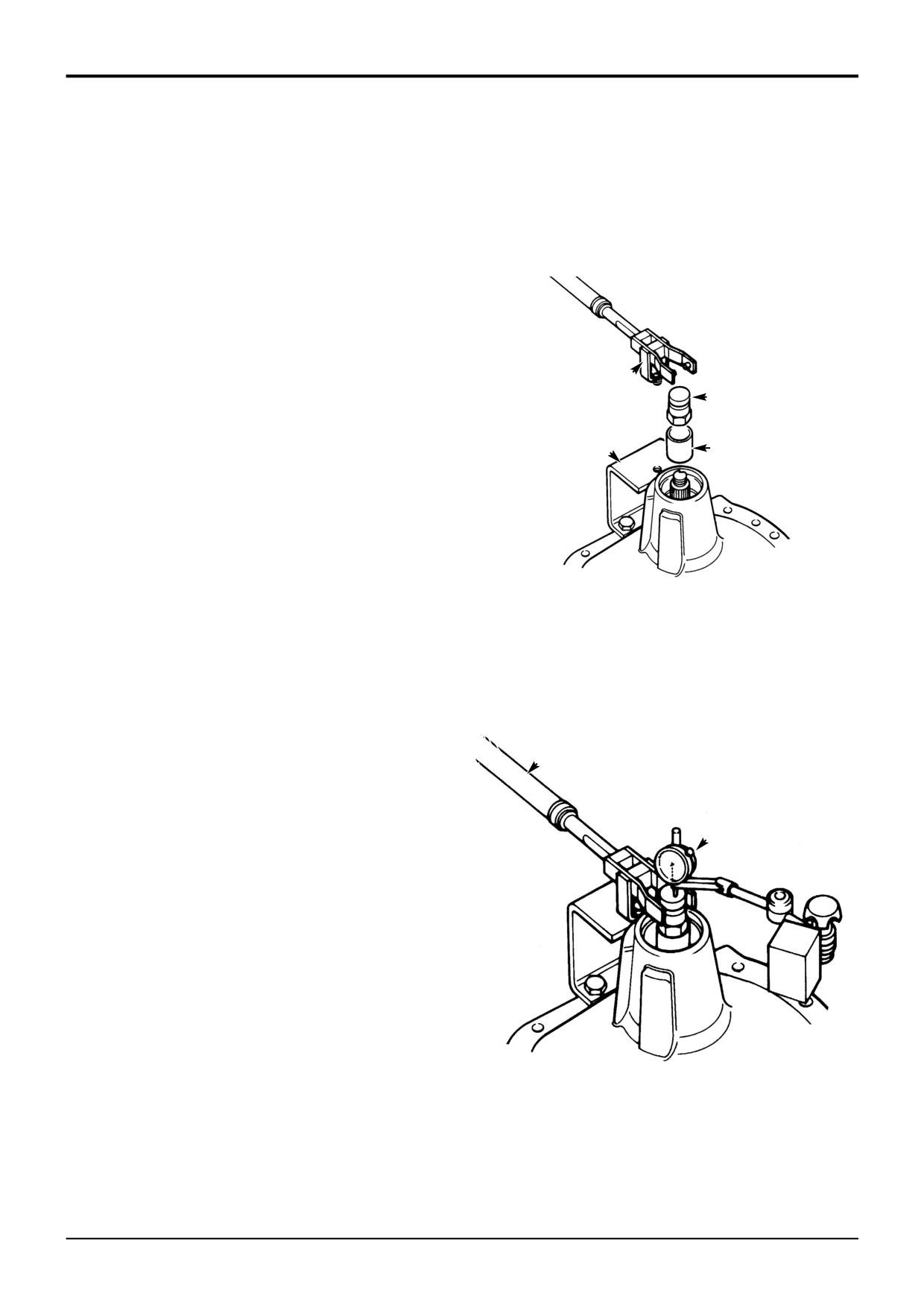
The outline procedure below refers also to the following
6
Fit special bracket D to the drive-head housing using
aspects of the drivehead assembly, which are covered
two M10 x 30 nuts and bolts. Fit special tool support
separately in detail as sub topics later in this section:
pillar E to bracket D so that the fork end engages in
adapter C. Ensure that fork E is centrally located on
Pinion Depth Setting
adapter C. If necessary, re-align bracket D to suit.
Collapsible Spacer Assembly
Crown Wheel and Pinion Meshing
Note: Both the crownwheel 20 and pinion 24 and the bevel
gears 14 and 16 are matched and should be renewed as
sets if any of their components are damaged or excessively
worn. The two differential housing halves 12 and 13 are also
matched. Do not use unmatched halves.
E
Make sure all bearings are lightly oiled before fitting and
C
setting. Make sure bearings are rotated whilst being set.
1
Determine the correct thickness required for the shims
29, refer to Pinion Depth Setting.
D
B
2
Fit shims 29 behind new bearing cup 28.
3
Fit new pinion head bearing cone 28 onto pinion 24.
4
Install pinion and bearings into the drive head casing.
348030
Install largest available solid spacer 30 e.g (14.20 mm)
and fit pinion tail bearing 26 (lightly oiled). Do not fit the
oil seal 25 at this stage.
7
Fit dial test indicator (DTI) F. Ensure that the DTI is
mounted on the drive head and not on bracket D.
Note: It should be noted that the axle is assembled using a
solid spacer. However, in the absence of the special tools
required or the correct size solid spacer 30 it is acceptable
8
Set torque wrench G to 35 Nm (25.8 lbf ft) and measure
to fit a collapsible spacer, refer to Collapsible Spacer
the end float while rotating the shaft.
Assembly.
5
Fit special tool sleeve B and special pinion shaft
G
adapter C. Tighten adapter C to approximately 50 Nm,
making sure the pinion is free to rotate and there is end
float, this will prevent any damage to the bearing. If the
pinion is not free to rotate or there is no end float at this
F
stage check the bearing is fitted correctly. Also check
the correct size spacer has been fitted.
348040
9803/3280
Issue 1
Section F
Transmission
Section F
83 - 5
Front Axle - SD70
83 - 5
9803/3280
Issue 1
Section F
Transmission
Section F
83 - 6
Front Axle - SD70
83 - 6
Drive Head - Assembly (cont’d)
9
To select the right size spacer 30, subtract the end float
16
Assemble the trunnion pin B, bevel gears 14 and 16
obtained at step 7 from the solid spacer size (14.20
and their thrust washers 15 and 17 into differential half
mm). Also subtract 0.04 mm to allow for theoretical
case 13.
bearing tolerance and pre load. The result is the size of
spacer to be fitted from the solid spacer setting kit. If
17
Position differential half case 12 onto half case 13,
there is no spacer of this size, fit the next nearest size
aligning the match-mark letters. Apply JCB
spacer, refer to Service Tools - Axles.
Threadlocker and Sealer to the threads of bolts 7, then
Example
fit and torque tighten to 56 Nm (42 lbf ft, 6 kgf m).
Temporary spacer size
14.20
Check the gears for free rotation.
Subtract end-float
0.25
18
Fit crownwheel 20 using new Verbus Ripp bolts 19
Total
13.95
tightened to 166 Nm (122 lbf ft, 16.9 kgf m).
Subtract tolerance & preload
0.04
Result
13.91
Note: Verbus Ripp bolts must not be reused.
(No spacer available this size, use next nearest size
spacer i.e 13.900)
19
Insall the differential assembly 10 onto the drive head
carrier 2.
10
Remove sleeve B and temporary spacer. fit correct size
20
Press taper roller bearing cone 9 onto the spigot of
spacer from solid spacer setting kit, refer to Service
case half 13.
Tools - Axles. During removal take care to avoid
damaging the outer bearing.
21
Fit bearing outer races 7 and 8, castellated nuts 5 and 6
to the drive head carrier 2.
11
Fit sleeve B. Tighten adapter C to no more than 50 Nm
to protect against bearing damage while spacer
22
Adjust castellated nuts 5 and 6 to give an increase in
selection is verified making sure the pinion is free to
input pinion rolling torque of between 1.36 - 2.5 Nm (12
rotate. Check there is no end float and pinion is free to
- 22 lbf in) more than that recorded in Step 11.
turn smoothly by hand. Remove adapter C and fit nut
16. Then check that rolling torque is less than 2.0 Nm. If
23
Measure the backlash between crownwheel 20 and
the rolling torque exceeds 2.0 Nm, check that the shaft
pinion 24, which should be 0.17 - 0.28 mm (0.006 -
has been assembled correctly.
0.010 in). Adjust castellated nuts 5 and 6 by equal
amounts when altering backlash. When backlash and
preload are both correct, fit roll pins 3 and 4.
Note: If the pinion is not free to rotate check the correct size
spacer has been fitted.
24
Check tooth marking to verify crownwheel and pinion
are set correctly, refer to Crownwheel and Pinion
12
If rolling torque measured at step 10 is too high, fit the
Meshing.
next larger size spacer. If rolling torque is too low, fit
the next smallest size spacer. If a correct spacer is not
25
Apply JCB Multigasket to the mating faces of drive
available from the range, check that drive head is
head carrier 2 and the axle casing. Fit the drive head
assembled correctly.
carrier to the axle casing with the crownwheel towards
the short drive shaft. Fit securing bolts 1 and tighten to
166 Nm (122 lbf ft, 16.9 kgf m).
13
Remove adapter C and sleeve B. Fit new oil seal 25,
grease between seal lips before fitting. Fit coupling
26
Reassemble both driveshafts and hub assemblies, refer
yoke 23 and NEW stake nut 22.
to Axle Hub and Driveshaft - Dismantling and
Assembly.
14
Progressively torque tighten stake nut 22, occasionally
rotating coupling yoke, up to 250 Nm. Providing the
27
Re-fill the hubs and differential with the correct grade of
correct size spacer has been selected the rolling torque
oil, refer to Section 3 Lubricants and Capacities.
should be between 2.3 and 3.4 Nm including seal drag.
28
Refit the propshaft, refer to Propshafts - Removing
and Replacing.
Note: The nut tightening torque can be increased to a
maximum of 300 Nm provided that the pinion rolling torque
does not exceed the maximum of 3.4 Nm.
15 Finally stake the nut 22 into the slot.
9803/3280
Issue 1
Section F
Transmission
Section F
83 - 7
Front Axle - SD70
83 - 7
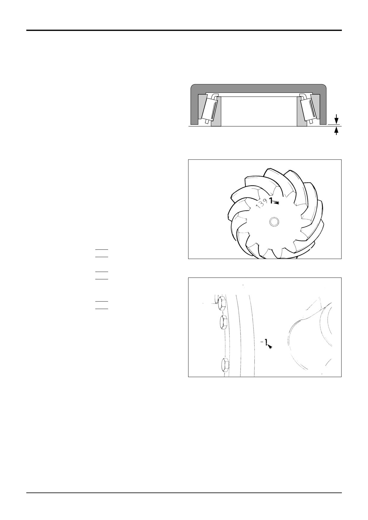
Pinion Depth Setting
1
Place new pinion head inner bearing assembly on a flat
surface and position service tool 892/00174 over the
bearing. Measure gap A (e.g. 0.20 mm) and add this to
the cup depth stamped on the tool (e.g. 30.01 mm) to
obtain the bearing depth.
A
2
From the face of the pinion, obtain the etched deviation
figure B (e.g. + 2) which is in units of 0.01 mm. If
positive, add this to the bearing depth; if negative,
subtract from the bearing depth.
A184400
3
Obtain the deviation figure C (e.g. - 1) stamped on the
differential housing bolt flange. If negative, add to
bearing depth; if positive, subtract from bearing depth.
4
Subtract the total of the above figures from the
standard value of 31.19 mm. The result will be the
thickness of shims required behind the pinion head
B
bearing cup.
Example (all dimensions in millimetres)
Cup depth
30.01
Gap A
+0.20
S256110
Bearing depth
30.21
Pinion deviation B (+ 2)
+0.02
Housing deviation C (- 1)
+0.01
Total
30.24
Standard value
31.19
Less Total above
30.24
Shim Thickness
0.95
Note: In the event that the setting data stamp has been
ommited from the drivehead casing, adopt the following
setting procedure:
C
Revise the shim pack size by the difference in setting height
marked on the old and new crownwheel pinion sets.
S256120
9803/3280
Issue 1
Section F
Transmission
Section F
83 - 8
Front Axle - SD70
83 - 8
Crownwheel and Pinion Meshing
Meshing of the gears should be checked by marking three of
the pinion teeth with engineers marking compound and
rotating the pinion.
The marking will then be transferred to the crown wheel
teeth.
Correct tooth marking.
A386940
Pinion too deeply in mesh.
Decrease the shim thickness between the pinion inner
bearing cup and the axle casing. Move the crown wheel
towards the pinion to correct the backlash.
A386950
Pinion too far out of mesh.
Increase the shim thickness between the pinion inner
bearing cup and the axle casing. Move the crown wheel
away from the pinion to correct the backlash.
A386960
9803/3280
Issue 1
Section F
Transmission
Section F
85 - 1
Front Axle
85 - 1
Removal and Replacement
(2 Wheel Drive Machines)
The removal and replacement procedures for the 2 wheel
drive axle (beam type) is the same as described on pages
F/80-1 and F/80-2. Dis-regard any information which is not
pertinent to the 2 wheel drive axle.
Please note when using a 'cradle' to remove the axle from
the machine, the balance point (see step 10, page F/80-2),
of the axle on 2 wheel drive machines will be the centre of
the axle, NOT offset as described on page F/80-2.
9803/3280
Issue 1
Section F
Transmission
Section F
86 - 1
Front Axle
86 - 1
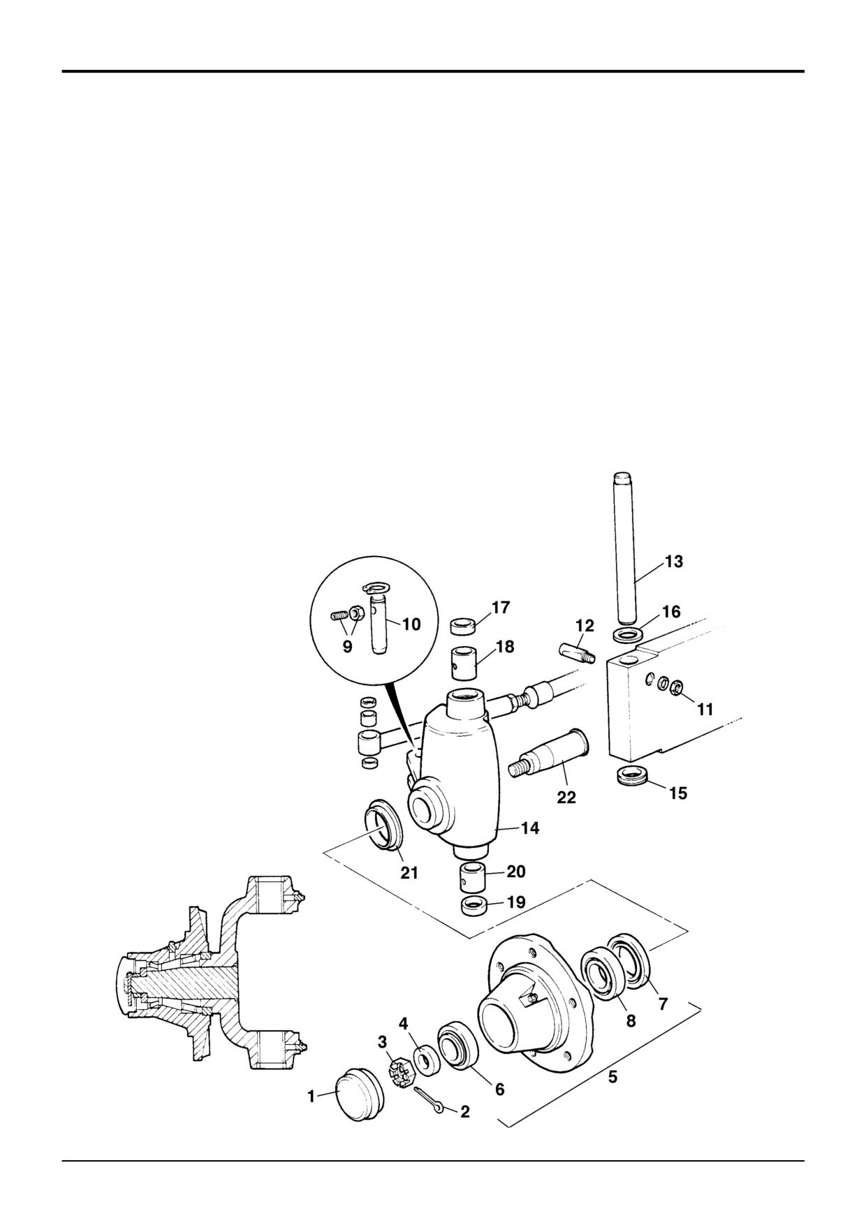
Dismantling and Assembly
(2 Wheel Drive Machines)
When Dismantling
Bed in bearings 6 and 8 by rotating hub in each direction
whilst tightening nut 3. When correct torque setting has
The numerical sequence shown on the illustration is
been achieved, back off one flat and fit split pin 2.
intended as a guide to dismantling.
For assembly the sequence should be reversed.
Torque Settings
A suitable press will be required to remove and replace stub
Item
Nm
kgf m lbf ft
axle 22.
3
40†
4.0†
30†
9
30
3.0
21
When Assembling
† Back off one flat before fitting split pin.
Fit bushes 18 and 20 with open ends of grease grooves
facing the axle beam.
Add shims 16 as required to give zero to 0.1mm (0.004in)
clearance between axle beam and bearing 15.
Apply JCB Lock and Seal to threads of bolt 9.
Pack JCB Special MPL Grease into hubs 5 and between lips
of seals 7.
S258280
9803/3280
Issue 1
Section F
Transmission
Section F
90 - 1
Rear Axle - PD70, SD80
90 - 1
Removal and Replacement
D
C
D
-238.14
B
H
H
E
F
J
L
M
A
K
G
A401300
9803/3280
Issue 1
Section F
Transmission
Section F
90 - 2
Rear Axle - PD70, SD80
90 - 2
Removal and Replacement (cont’d)
Replacement
! WARNING
Replacement is the reverse of the removal sequence.
A raised and badly supported machine can fall on you.
Position the machine on a firm, level surface before
raising one end. Ensure the other end is securely
! WARNING
chocked. Do not rely solely on the machine hydraulics or
If, for whatever reason, a wheel stud is renewed, all the
jacks to support the machine when working under it.
studs for that wheel must be changed as a set, since the
remaining studs may have been damaged.
Disconnect the battery, to prevent the engine being
2-3-2-8
started while you are beneath the machine.
GEN 1-1
Whenever a wheel has been removed, check the wheel nut
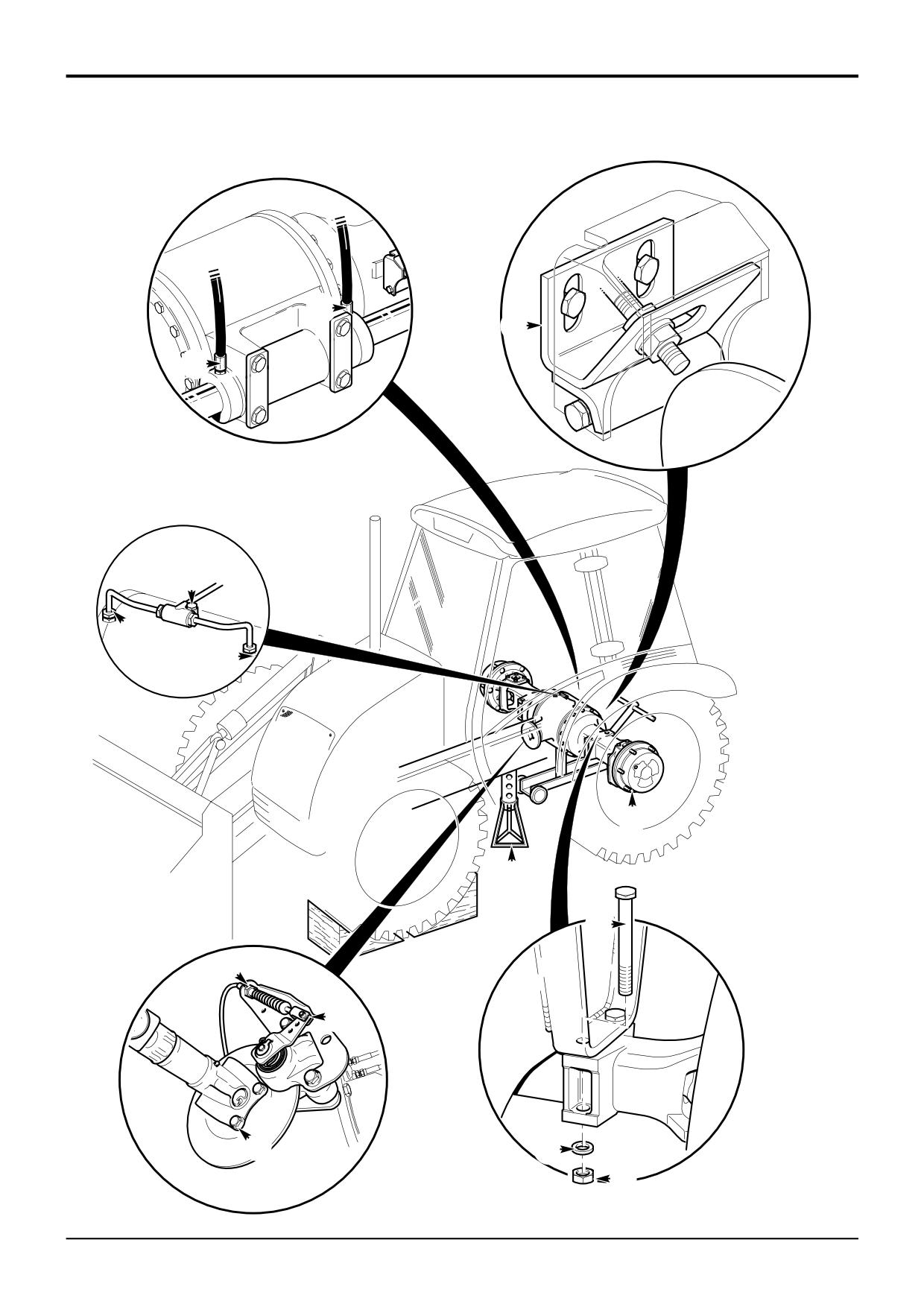
Removal
torques every two hours until they stay correct.
! WARNING
! WARNING
When the propshaft is disconnected the parking brake
Bleed the brake system before driving the machine.
will no longer function. The machine must be securely
BRAK 1-6
chocked to prevent any machine movement before
disconnecting the propshaft.
TRAN 1-3
Bleed the brake system as described in Section G, Service
Procedures.
Removing
Check and adjust the operation of the parking brake as
1
Release the parking brake. Loosen the parking brake
described in Section G, Service Procedures.
cable bulkhead nuts at the bracket L. Disconnect the
cable from the calliper M. Tie the cable up, out of
Apply JCB Threadlocker and Sealer to the threads of bolts
harms way.
A.
2
Remove bolts A to disconnect the drive shaft from the
SD 80 Steer axles only; If the setting of the steering
axle.
proximity switch has been disturbed, then complete the rear
axle proximity switch setting procedure, as described in
3
Disconnect the brake pipes from the brake piston
Section H, Service Procedures.
housings, shown at H. Remove tee piece B retaining
bolt and remove the tee piece. Blank off exposed
Torque Settings
connections.
Item
Nm
kgf m
lbf ft
4
SD 80 Steer axles only; Remove the cover C from the
A
79
8
58
proximity switch and then remove the bracket and
E
680
69
500
switch assembly.
G
607
62
448
5
SD 80 Steer axles only; Label and then disconnect
hydraulic pipes D from the steer rams, blank off all
exposed connections.
6
Loosen the road wheel retaining nuts E.
7
Make sure that the front wheels are blocked, use the
stabiliser legs to raise the rear end of the machine with
the wheels and tyres clear of the ground.
8
Prop the machine on each side as shown at F.
9
Remove the rear road wheels.
10
Position a jack underneath the balance point (centre) of
the axle and support the axle weight.
Note: Attach a 'cradle' to the jack that will partially embrace
the axle.
11
Remove nuts G, bolts J and washers K.
12
Lower the jack and remove the axle.
9803/3280
Issue 1
Section F
Transmission
Section F
91 - 1
Rear Axle - PD70, SD80
91 - 1
8
7
9
15
16
5
11
10
17
13
14
12
3
2
B
A
2
3A
4
1
6
378120
9803/3280
Issue 1
Section F
Transmission
Section F
91 - 2
Rear Axle - PD70, SD80
91 - 2
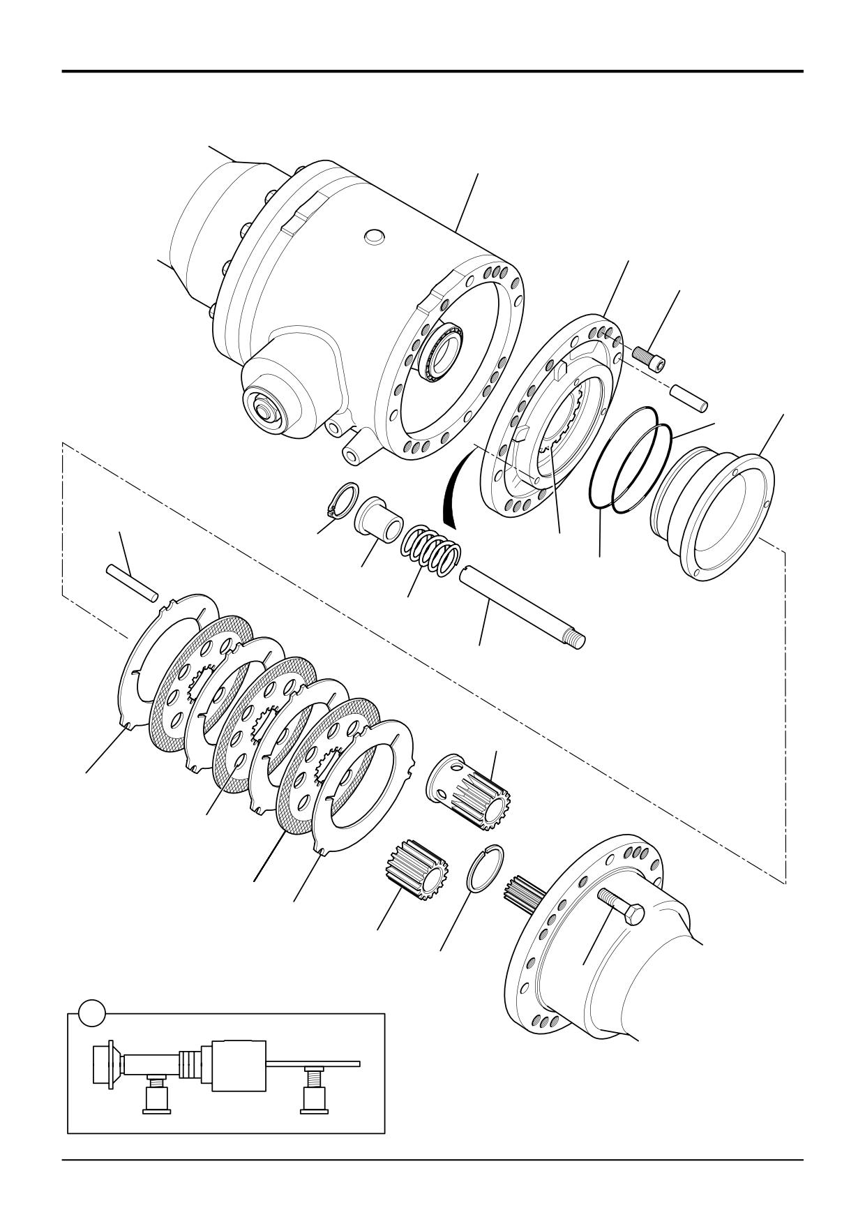
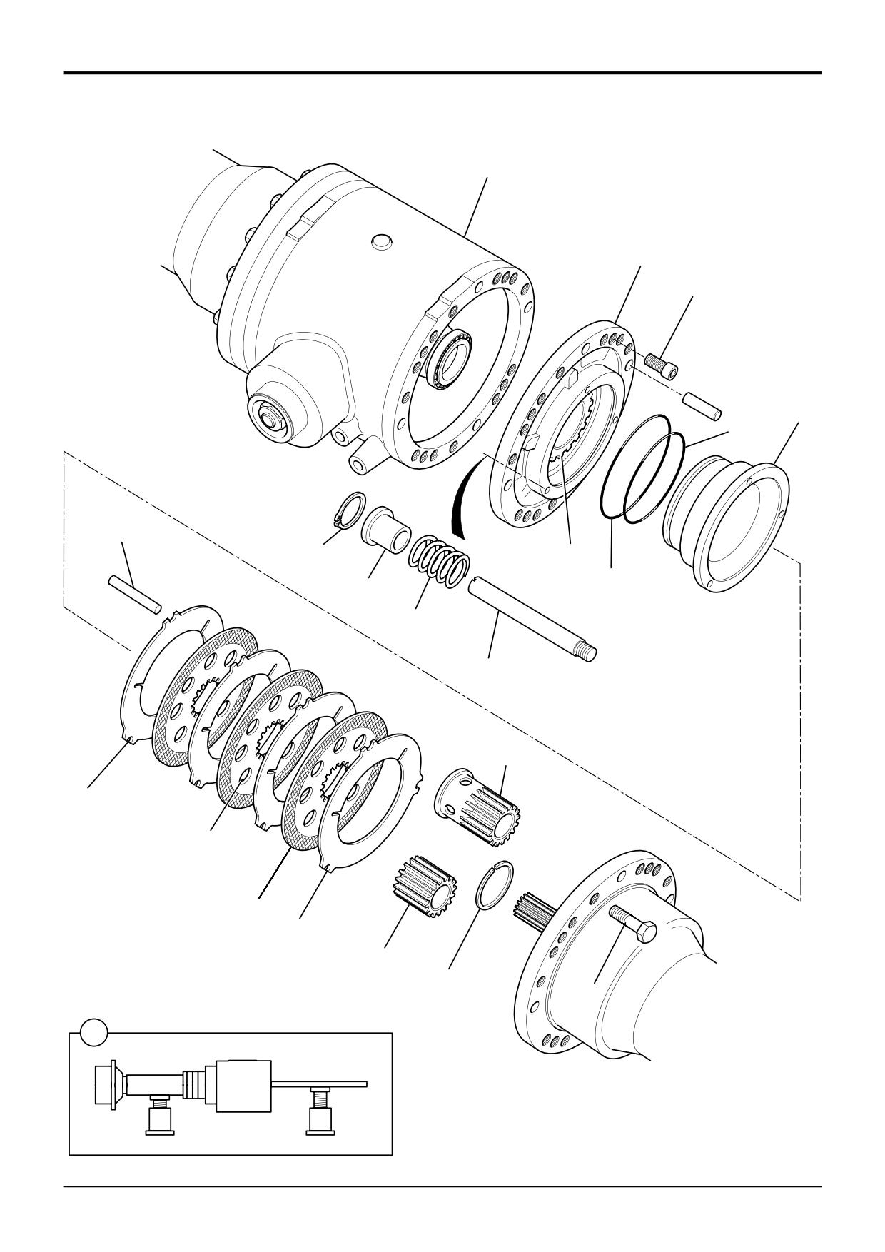
Brakes (with controlled back off)
Axles are fitted with brake controlled back off to maintain a
9
Match mark the brake piston housing 7 and the drive
constant clearance of 0.6mm (0.02in) within the brake pack.
head. Undo four capscrews 9 and remove the brake
housing and piston assembly.
It is important that only one side at a time is dismantled to
prevent damage to the bearings and preserve the
Note: Do not disturb nut 10 otherwise the bearing pre load
crownwheel and pinion backlash setting.
will have to be reset.
! WARNING
11
Remove circlips 11, remove back off pins 12, tension
bushes 13 and springs 14.
A raised and badly supported machine can fall on you.
Position the machine on a firm, level surface before
12
Remove brake piston 15 from brake housing 7.
raising one end. Ensure the other end is securely
chocked. Do not rely solely on the machine hydraulics or
13
Remove and discard seals 16 and 17. Inspect the
jacks to support the machine when working under it.
housing bore for damage and scoring. Nicks or cuts in
the seals may be responsible for loss of brake fluid.
Disconnect the battery, to prevent the engine being
started while you are beneath the machine.
GEN 1-1
Dismantling
1
It is recommended that the axle be removed from the
machine when dismantling the rear axle brakes.
2
Remove bolts 1. Use a heavy duty socket to unscrew
them.
3
Jack the axle arm off the drive head, using the drive
head securing bolts. Remove all traces of gasketing
from the mating faces.
4
There are two counterplates 2, one at each end of the
brake pack, which are not secured to the plate carrier 3.
If the plates are to be re-used, note their positions and
which way round they are then withdraw the brake
pack.
5
Remove the circlip 4. If the brake pack is to be re-used,
note the positions of the plates before removing them.
6
Wear limit of friction plates is to the depth of the cross
hatching A. Check all plates for flatness and damage.
(Some scoring of the counterplates is normal.) Renew
the brake pack complete if worn or damaged. Do not
renew individual plates.
7
Remove the three reaction pins 5. Inspect for damage.
Note: If new brake and friction plates are being fitted new
brake back off pins and tension bushes must also be fitted.
Failure to do so could result in the brake being permanently
on.
8
Before removing the brake housing and piston
assembly support the differential with a drive shaft or
other suitable support, as shown at 6.
9803/3280
Issue 1
Section F
Transmission
Section F
91 - 3
Rear Axle - PD70, SD80
91 - 3
8
7
9
15
16
5
11
10
17
13
14
12
3
2
B
A
2
3A
4
1
6
378120
9803/3280
Issue 1
Section F
Transmission
Section F
91 - 4
Rear Axle - PD70, SD80
91 - 4
Brakes (with controlled back off)
continued
Assembly
11
Install one counterplate 2 into the housing, then the
1
Clean all sealant from the mating faces of the drive
brake pack, then the other counterplate. Return re-used
head and the brake piston housing.
counterplates to their original positions. Push the brake
pack fully home.
2
Fit new seals 17 and 16. Make sure they seat squarely
in their grooves.
12
Apply JCB High Strength Gasketing to the mating face
of the drive head, and JCB Threadlocker and Sealer to
3
Carefully press the piston 15 all the way into its housing
the threads of bolts 1. Locate the axle arm onto the
7. Make sure the brake back off holes in the piston and
drivehead, with the embossed word 'TOP' on the axle
housing align.
arm uppermost.
4
Apply JCB Threadlocker and Sealer to threads of back
13
Fit bolts 1 and torque tighten.
off pins 12. Screw the back off pins 12 into the brake
piston and fit the springs 14 over the back off pins.
Note: Check the grade of bolts fitted. Grade 8.8 should be
tightened to 244 Nm (178lbf ft, 24.9 kgf m), grade 12.9
5
Place the tension bush 13 over the back off pin 12.
should be tightened to 400 Nm (295 lbf ft, 40.8 kgf m).
Using a suitable tool (steel tube) drive the tension bush
onto the back off pin using a soft face hammer until the
circlip 11 can just be fitted.
6
Apply JCB High Strength Gasketing to the drive head
mating face, then fit the brake piston housing assembly.
Ensure that the match marks made during dismantling
are aligned.
7
Fit capscrews 9 and torque tighten to 56 Nm (42 lbf ft,
5.7 kgf m).
8
Remove the differential support.
9
Assemble the friction plates and counterplates 2 onto
the brake carrier 3. If the original brake pack is being re-
used, return the plates to their original positions, see
'Dismantling'. Soak new friction plates in JCB Special
Gear Oil before assembly. Fit circlip 4.
On assembly of the brake packs, the oil flow holes B
must be aligned with each other when being fitted to
the brake plate carrier.
Note: Item 3A is fitted to non steer axles.
Note: The illustration is typical only, refer to parts book or
General Bulletin 061 (G20/N.Am) for exact number of friction
and counter plates.
10
Locate the three reaction pins 5 into their grooves,
securing them with grease. Push the pins fully into their
location holes in the housing.
9803/3280
Issue 1
Section F
Transmission
Section F
92 - 1
Rear Axle - SD80
92 - 1
14
13
5
4
11
12
2
7
10
8
6
20
19
3
22
23
24
25
21
18
26
15
5
16
2
17
1
A313631
9803/3280
Issue 1
Section F
Transmission
Section F
92 - 2
Rear Axle - SD80
92 - 2
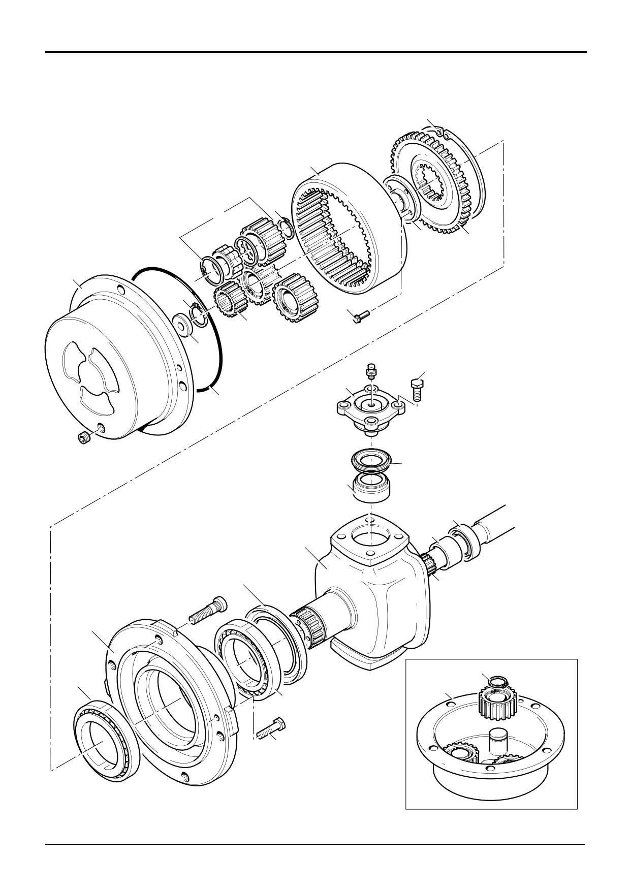
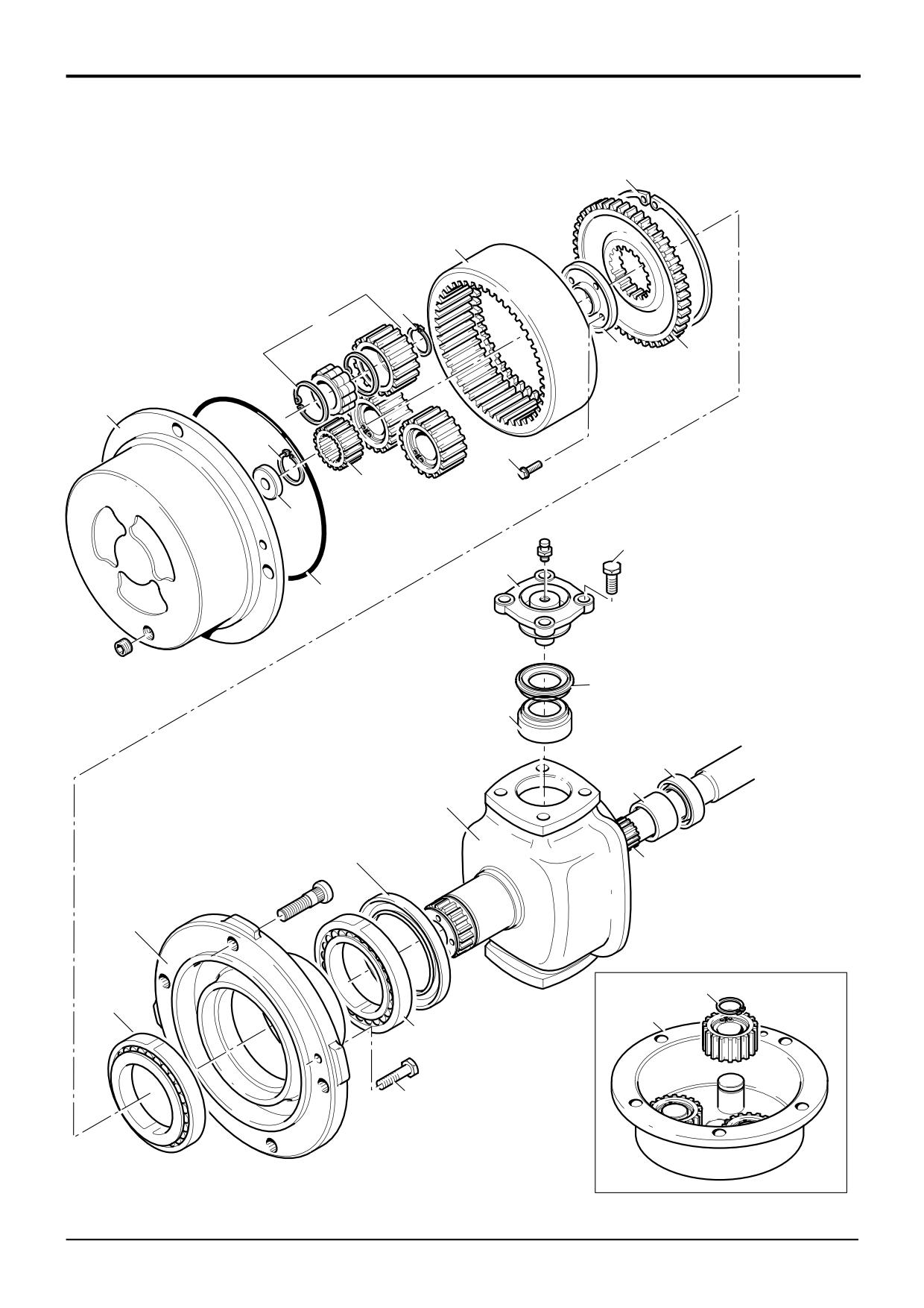
Hub - Dismantling
! WARNING
A raised and badly supported machine can fall on you.
14
Remove and discard combination oil seal 18.
Position the machine on a firm, level surface before
raising one end. Ensure the other end is securely
15
Mark the position of top and bottom trunnions 19, undo
chocked. Do not rely solely on the machine hydraulics or
bolts 20 and remove trunnions 19. Withdraw the hub
jacks to support the machine when working under it.
carrier 21.
Disconnect the battery, to prevent the engine being
Note: Trunnions may be removed easily by pumping grease
started while you are beneath the machine.
through the grease nipple.
GEN 1-1
16
Using a puller, remove the trunnion seal 22 and bearing
1
Disconnect power track rod. Drain oil from hub.
23.
2
Remove screws 1.
17
Remove seal 24 and needle roller bearing 25 from hub
carrier 21.
3
Lever off the planet gear carrier 2 at the levering points.
Remove and discard the 'O' ring 3.
Note: Seal and needle roller bearing may be left on drive
shaft. Production axles may be fitted with foam ‘masking
4
Remove planet gears 4 only if defective. Note that
rings’. These are used to protect the shaft from paint during
gears can only be removed as assemblies, which
axle spraying. The rings can be removed and discarded.
comprise the gear, the bearing and two 'L' shaped
circlips. To remove a planet gear, first remove the
18
Withdraw drive shaft 26.
external circlip 5.
5
Pull off the planet gear assembly 4.
6
The driveshaft thrust pad 6 is drilled and tapped M6 for
removal purposes.
7
Remove circlip 7 to allow the sun gear 8 to be slid off
the drive shaft.
8
Remove Verbus Rip bolts 10. These bolts are very tight
and care must be taken not to distort the bolt heads.
Use as short an extension bar as possible with a six
sided socket. Discard the bolts after removal.
Note: Fretting between the hub swivel and annulus carrier
mating faces might be evident; this condition is normal, do
not attempt to repair.
If the hub swivel and annulus carrier are to be renewed they
must be renewed as a pair, not individually
9
Remove retaining plate 11.
10
Mark the relationship between the annulus carrier,
annulus ring and hub swivel, remove the annulus carrier
12 with annulus ring 13.
11
Remove circlip 14 to separate the annulus ring 13 from
the annulus carrier 12.
12
Pull off the bearing carrier 15 together with the outer
bearing 16.
13
Pull off the inner bearing 17.
9803/3280
Issue 1
Section F
Transmission
Section F
92 - 3
Rear Axle - SD80
92 - 3
14
13
5
4
11
12
2
7
10
8
6
20
19
3
22
23
24
25
21
18
26
15
5
16
2
17
1
A313631
9803/3280
Issue 1
Section F
Transmission
Section F
92 - 4
Rear Axle - SD80
92 - 4
Hub-Assembly
9
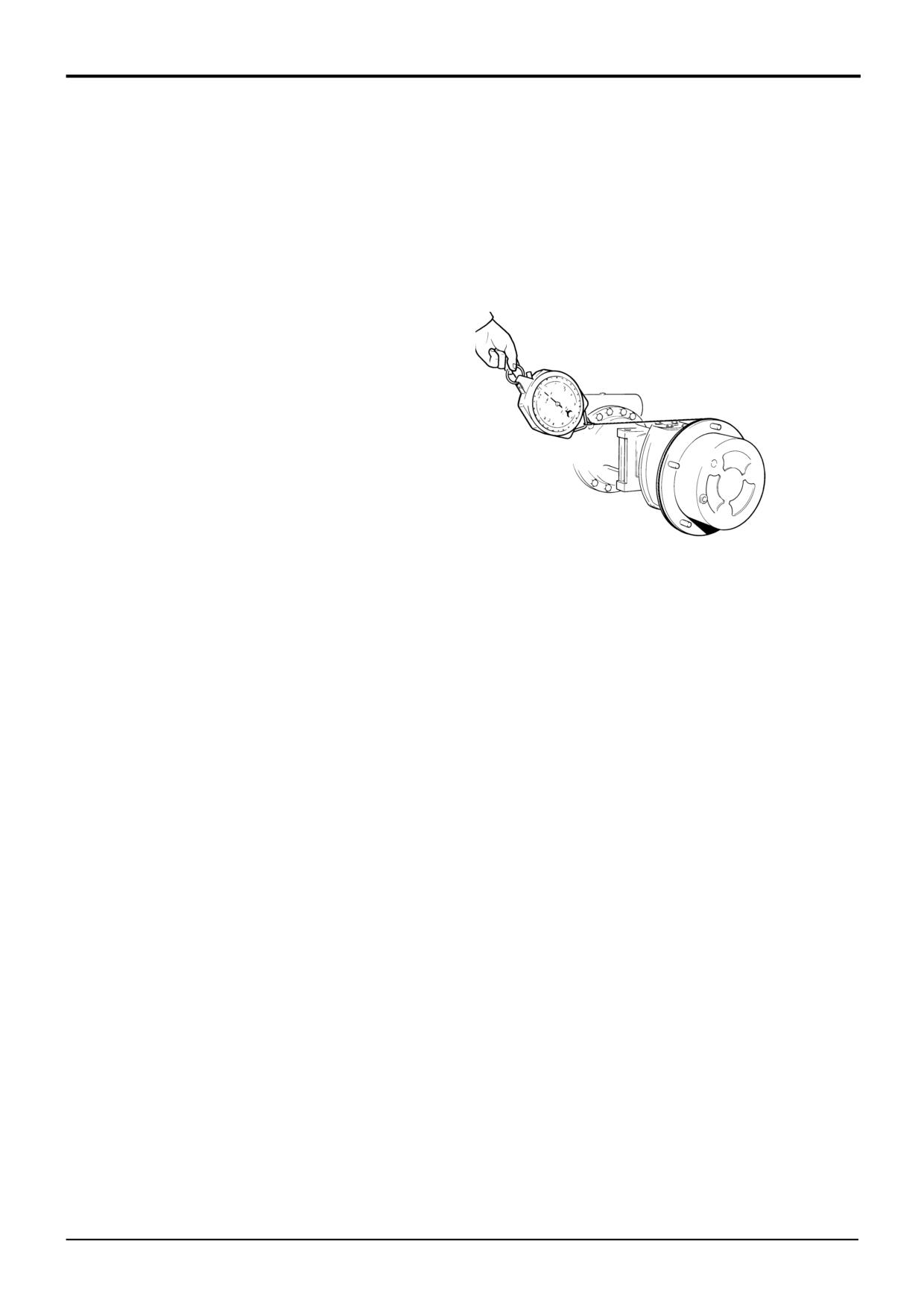
Measure seal drag rolling force as follows:
a Refit the planet gear carrier 2 - DO NOT FIT THE
1
Fit drive shaft 26 inner end into splines of differential
SUN GEAR 8.
gears.
b Use a spring balance and cord wrapped around
2
Fit needle roller bearing 25 and seal 24 into hub carrier
planet gear carrier 2 as shown. Pull the spring
21. Pack grease between the lips of seal 24.
balance so that the hub rotates, do several times
to let the seal bed in and record the reading.
Note: Do not force fit bearing 25 and make sure the
Remove planet gear carrier 2.
manufacturer’s mark is facing out.
3
Locate hub swivel, aligning relationship lines, assemble
top and bottom trunnions 19 together with trunnion seal
22 and bearing 23. Apply Threadlocker and Sealer to
the threads of bolt 20, torque tighten trunnion retaining
bolts 20 to 98 Nm (72 lbf ft).
4
Lightly oil the inner wheel bearing race. Assemble the
bearing cup and bearing race 17 into the bearing carrier
15.
5
Fit a new combination seal 18 into the bearing carrier
15 so that the chamfer faces the hub swivel. Do not
disassemble seal or use excessive force when fitting.
Do not lubricate before fitting. Use service tool
10
Torque tighten bolts 10 evenly to 166 Nm (122 lb ft,
(892/00891) and spacer to drive the seal squarely into
17 kgf).
the carrier until flush.
11
Measure the rolling force as follows:
6
Lightly oil the outer wheel bearing race. Assemble the
bearing cup and bearing race 16 into the bearing carrier
a Refit the planet gear carrier 2 - DO NOT FIT THE
15. Fit bearing carrier assembly onto axle stub.
SUN GEAR 8. Use a spring balance and cord
wrapped around the planet carrier as shown. Pull
Note: The bearing carrier must be fully supported during the
the spring balance so that the hub rotates and
fitting operation; do not allow any weight to rest on the
record the reading.
bearings, otherwise the inner bearing will be displaced and
damage the seal.
b To get the rolling force, subtract seal drag rolling
force (see step 9) from reading obtained at this
7
Align relationship marks made on dismantling.
step, the result should be 64 to 117N (14 to 26 lbf).
Assemble the annulus ring 13 to the annulus carrier 12.
Secure with circlip 14.
c If the resulting figure is outside these limits, check:
the seal is fitted correctly; and/or renew bearings if
8
Fit annulus assembly in the same angular position as
necessary; and/or new fitted components.
removal, fit retaining plate 11 using new bolts 10. Do
Remove planet gear carrier 2.
not fully tighten bolts but allow the bearing carrier to
rock slightly.
12
Press the drive shaft thrust pad 6 (chamfered side
lowermost) into the recess in the planet carrier 2.
Note: Steps 10 to 12 describe measurement of rolling force.
To measure rolling torque (simplified process), a special tool
13
Fit new planet gears 4 in place of any that were
is required. See Service Tools in this section.
removed.
14
Slide the sun gear 8 (chamfer to be inboard) onto the
drive shaft 26 and secure with circlip 7. Fit a new 'O'
ring 3 in place of the one discarded during dismantling.
15
Fit the planet carrier 2 onto the bearing carrier 15
ensuring that the two tapped holes are in line with
those on the bearing carrier. Fit and tighten screws 1
after applying Threadlocker and Sealer to the threads.
Torque tighten screws to 56 Nm (41 lb ft).
16
Fill hubs with correct grade oil.
9803/3280
Issue 1
Section F
Transmission
Section F
93 - 1
Rear Axle - PD70
93 - 1
Hub-Dismantling & Assembly
The procedures for dismantling and assembling the hub on a
PD70 axle are virtually the same as for a SD80 axle -
described on the previous pages (F/92-1 to F/92-4).
However, note that the wheel bearing carrier (shown as item
15 on page F/92-1) is mounted directly on to the axle arm.
Disregard references to the hub carrier (shown as item 21 on
page F/92-1).
9803/3280
Issue 1
Section F
Transmission
Section F
94 - 1
Rear Axle - SD80, PD70
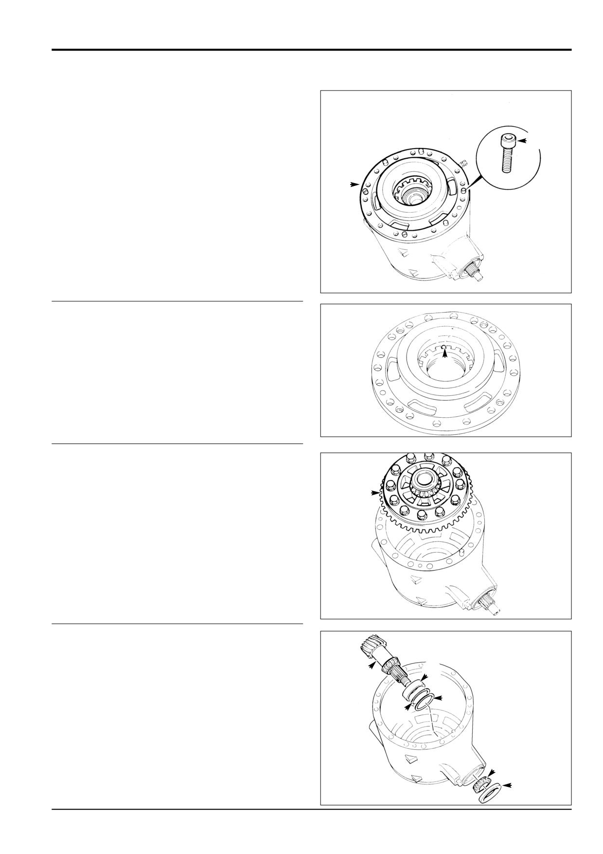
94 - 1
Drive Head-Dismantling
As the drivehead cannot be dismantled whilst fitted on the
machine, we recommend that the complete axle is removed.
See Brakes and Hub and Driveshaft for axle arm removal
1
procedure.
The crownwheel and pinion are matched and should be
renewed as a pair if either one is damaged or excessively
2
worn. The two differential case halves are also matched as
are the differential side gears and planet gears, do not use
unmatched halves or gears.
1
Position the drive head as shown, with the crownwheel
at the top.
S256050
2
Match - mark the brake piston housing and drive head.
Pull off the brake piston housing.
3
Drive out the differential side nut locking pin, to allow
readjustment on assembly. Remove the other brake
piston housing only if damaged, but remove its locking
pin regardless (to allow sideload adjustment on
assembly).
3
S256060
4
Lift out the crownwheel/differential assembly.
Note: If both brake piston housings are to be removed,
mark the crownwheel end of the drive head casing to ensure
4
that the assembly is returned to its original position.
S256070
5
Using a soft faced hammer, hit the pinion end shaft until
the pinion is free from its front bearing, then withdraw
the pinion.
7
5
6
Withdraw the pinion seal and outer bearing cone.
7
7
If necessary, drive out the pinion inner bearing cup and
7
shims. Discard the shims. Repeat for the outer bearing
cup if required. Note that there are no shims for the outer
bearing cup.
6
S256080
6
9803/3280
Issue 1