JCB 3CX, 4CX, 214e, 214, 215, 217 & VARIANTS Backhoe Loader. Service Manual - page 26
Section F
Transmission
Section F
69 - 4
Service Procedures
69 - 4
Powershift Gearbox - 6 speed
ShiftMaster Diagnostics - User Guide
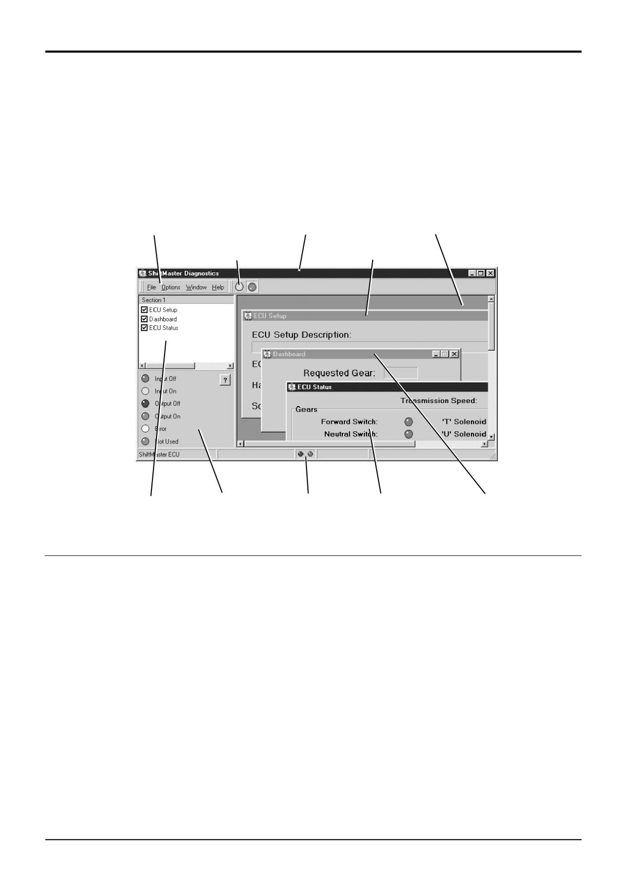
5. ShiftMaster Diagnostics: Overview
There are several key elements to the ShiftMaster
Diagnostics tool. These can be seen labelled below. Each
element is explained in detail in later sections.
Menu Bar
Main Window
Page Display Area
Start/Stop Buttons
ECU Setup Page
Page List
LED Status Key
Status Bar
ECU Status Page Dashboard Page
S404250
Navigating within ShiftMaster Diagnostics
Navigation is designed to be via a mouse. On Laptop PCs
Note: This can be particularly useful for certain Laptop PCs
this may take the form of a small joystick or touch sensitive
where the mouse/joystick can be over-sensitive. Try out the
pad and some buttons, usually located near to the
following, it may come in useful one day.
keyboard.
There are two main methods of navigation described below;
As with most Windows based programs, it is possible to
navigate ShiftMaster Diagnostics using the keyboard by
·
Pressing the ALT key will cause the File option on the
pressing certain combinations of keys.
Menu Bar to be highlighted. You can then use the
arrow keys to navigate the menus.
·
Notice that all the menu items on the Menu Bar have a
letter that is underlined (e.g. the 'F' in File). Holding
down the ALT key and pressing the required letter key
will activate that option (i.e. either open the menu or
execute a function). For example, if you wish to open
the Preferences Dialogue this can be done by pressing
ALT + O (to open the Options menu) then ALT + P (to
execute the Preferences… option).
9803/3280
Issue 1
Section F
Transmission
Section F
69 - 5
Service Procedures
69 - 5
Powershift Gearbox - 6 speed
ShiftMaster Diagnostics - User Guide
6. Menu Bar
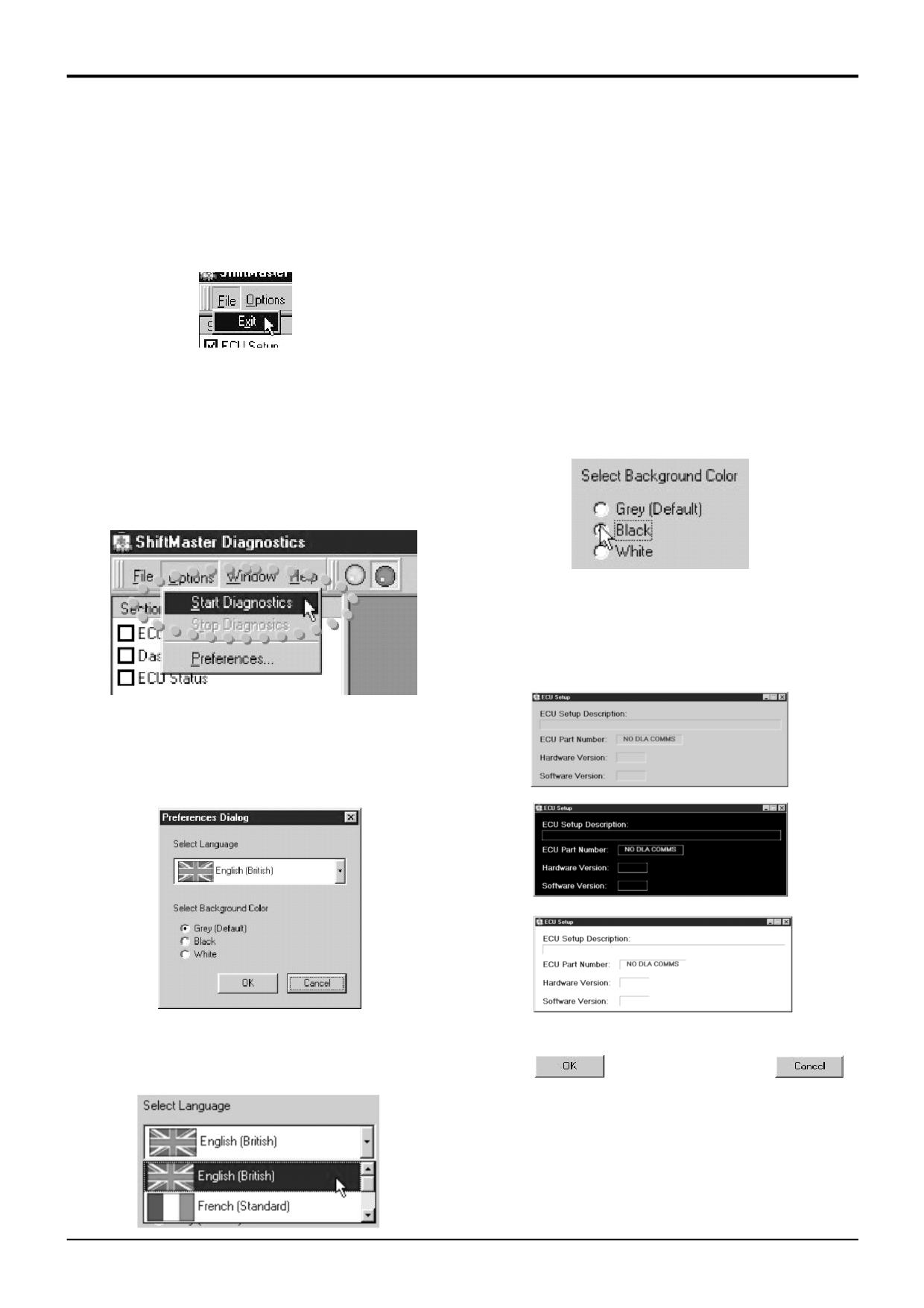
File Menu
· English (British)
The File Menu contains and Exit option to close down the
· French (Standard)
program.
· German (Standard)
· Spanish (Modern Sort)
Note: The language option only effects text within the Main
Window (e.g. Page List, LED Status Key, etc…). At present
S404260
language support is not offered for the text within the Page
On exiting the program communications with both ECU and
displays.
DLA are shut down.
The Preferences Dialogue also offers the ability to change
Options Menu
the backg7round colour of the Page displays. Select the
Select either:
required backg7round colour using the radio buttons.
Start Diagnostics to commence communications with the
ShiftMaster ECU.
or
S404300
Note: When using a laptop PC it can often be difficult to see
the screen in bright sunlight. Changing the backg7round
colour can help improve the contrast (especially with the
different LED colours) and so make viewing the screen
easier. Examples of the different colours are shown below;
S404270
Stop Diagnostics to cease communications.
Clicking on the Preferences… option opens up the
Preference Dialogue.
S404310
S404320
S404280
S404330
From the Preferences Dialogue there is support for multiple
Once your preferences have been selected either:
languages. Use the drop-down menu and scroll bar to chose
the required language. Languages presently on offer are:
Click on
to apply them or click on
to leave them unchanged.
S404290
9803/3280
Issue 1
Section F
Transmission
Section F
69 - 6
Service Procedures
69 - 6
Powershift Gearbox - 6 speed
ShiftMaster Diagnostics - User Guide
Window Menu
Fault Finding Guide: Provided to help the user to
Like most other Windows based programs where there are
understand how the PS760 gearbox electrical system
multiple sub-windows or Pages used, there are usually
operates. This Guide also offers advice on fault diagnosis
options to organise how they are laid-out. ShiftMaster
along with example scenarios, hints and tips.
Diagnostics is no different and offert the following options;
· Cascade
· Tile Horizontally
· Tile Vertically
Note: Laptop PCs, particularly older ones, tend to have a
low screen resolution. If this is the case then the Horizontal
S404370
and Vertical tile options will probably be of little use and
Cascade will offer the best advantage.
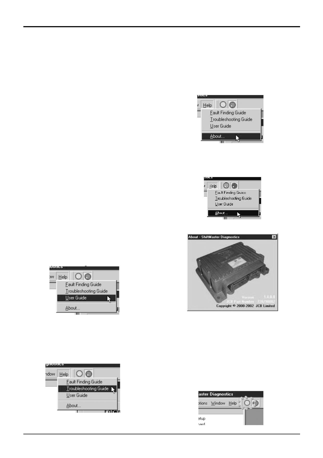
Selecting the About… option will bring up a window
Help Menu
showing the JCB part number and the version number of the
installed copy of ShiftMaster Diagnostics.
To assist the Service Engineer, ShiftMaster Diagnostics is
supplied with a set of documentary Guides. These Guides
can be accessed directly from within the ShiftMaster
Diagnostics tool itself, via the Help menu.
Note: All the Guides are provided in Adobe Acrobat PDF
format. In order to read these guides the user must first have
the Adobe Acrobat Reader installed on the PC. This
S404380
software is supplied on the JCB CD-ROM where full
installation instructions are provided.
At present these guides are as follows;
User Guide: This file is provided to explain how all the
functions of the ShiftMaster Diagnostics tool operate.
S404390
S404360
Troubleshooting Guide: Sometimes users may experience
problems with getting ShiftMaster Diagnostics to
7. Start/Stop Buttons
communicate properly with the ShiftMaster ECU. The
Trouble shooting Guide has been provided to explain
These offer the same function as the Start Diagnostics and
possible causes of problems with communications.
Stop Diagnostics options within the Options Menu.
To start the ShiftMaster Diagnostics tool communicating
with the ShiftMaster ECU simply click on the Start Button
(big green LED) at the top of the Main Window.
Similarly, click on the Stop Button (big red LED) to cease
communications.
S404240
S404400
9803/3280
Issue 1
Section F
Transmission
Section F
69 - 7
Service Procedures
69 - 7
Powershift Gearbox - 6 speed
ShiftMaster Diagnostics - User Guide
8. Page List
10. ECU Setup Page
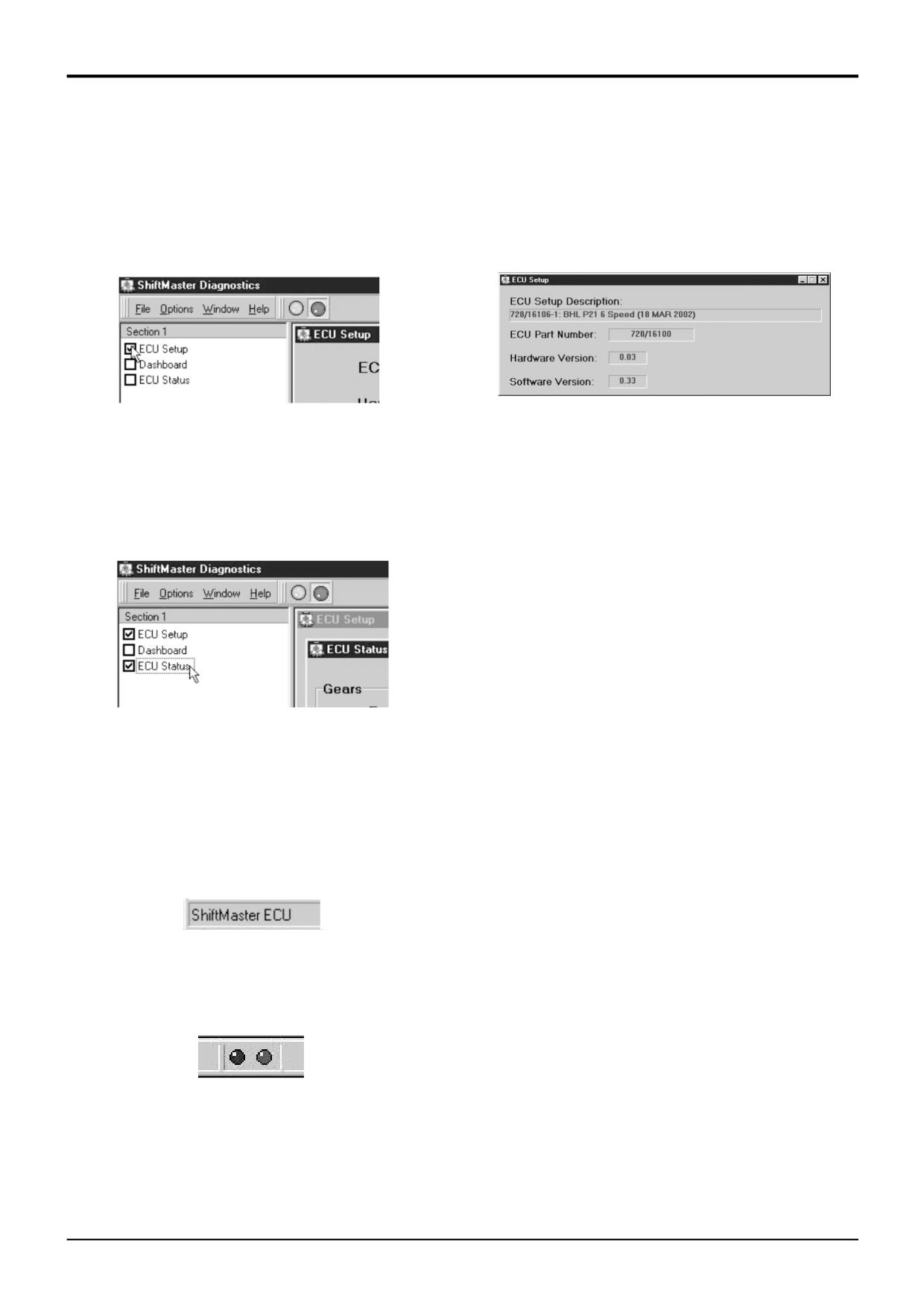
In the top left corner of the main window is displayed a list of
This page displays crucial information about the ECU
pages which can be displayed.
configuration.
S404410
S404450
Clicking in the box next to the required page with make that
page appear in the main window display area. (A tick will
It is always useful to confirm that this is the correct
also appear in the box to show it is being displayed.)
configuration for the machine before commencing any fault
finding.
At any time the user may swap between displayed pages
simply by clicking on the title of the required page in the
The ECU Setup Page displays the following information;
page list.
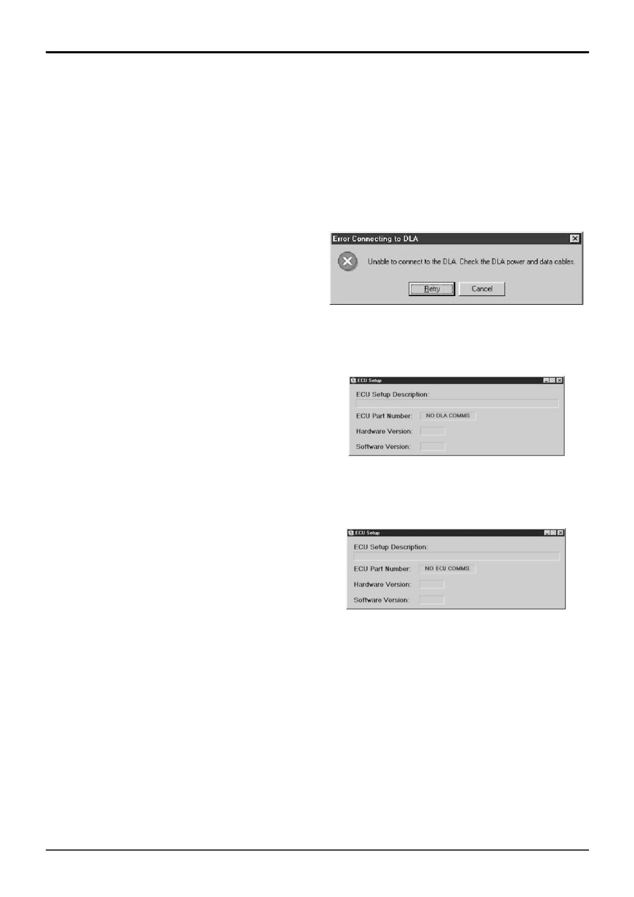
ECU Part Number
This will display the part number of the connected
ShiftMaster ECU.
If there are communications errors present then this will
contain either;
a). 'NO DLA COMMS' if there are problems communication
with the DLA, or
b). 'NO ECU COMMS' if the DLA is working but the
ShiftMaster ECU is not responding.
S404420
9. Status Bar
Note: If communications problems are suspected then
please consult the accompanying Troubleshooting Guide
There are 2 items of interest displayed on the Status Bar,
for further information.
which is located along the bottom of the ShiftMaster
Diagnostics Main Window.
Hardware Version
This hardware version is a reference to the build level of the
Connected ECU: The type of ECU connected to the
electronics. Future developments may mean that hardware
ShiftMaster Diagnostics tool is indicated on the far left side
upgrades are required. This may effect which software can
of the Status bar.
be used.
Software Version
S404430
The software version refers to the issue level of the ECU
operating software. Again, future developments may require
software revisions.
CAN communications: Two small LEDs indicate data being
transmitted (red) and received (green) over the CAN
ECU Setup Description
communications link.
As well as its' operating software, the ShiftMaster ECU also
stores a group of Setup Data (or Settings). This Setup Data
is used to tailor how a certain ECU part number functions.
The Setup Data is loaded during the manufacturing process
S404440
and has been approved for use in the intended application.
These LEDs can be seen to be flashing rapidly as data is
Contained as part of the Setup Data is a Description. This
transported. This can be another useful aid to determining
Description is what is displayed here. The Engineer can use
the state of any established communications.
this description to verify that the correct Setup Data is being
used.
At present there is no service tool available to load new
Setup Data.
9803/3280
Issue 1
Section F
Transmission
Section F
69 - 8
Service Procedures
69 - 8
Powershift Gearbox - 6 speed
ShiftMaster Diagnostics - User Guide
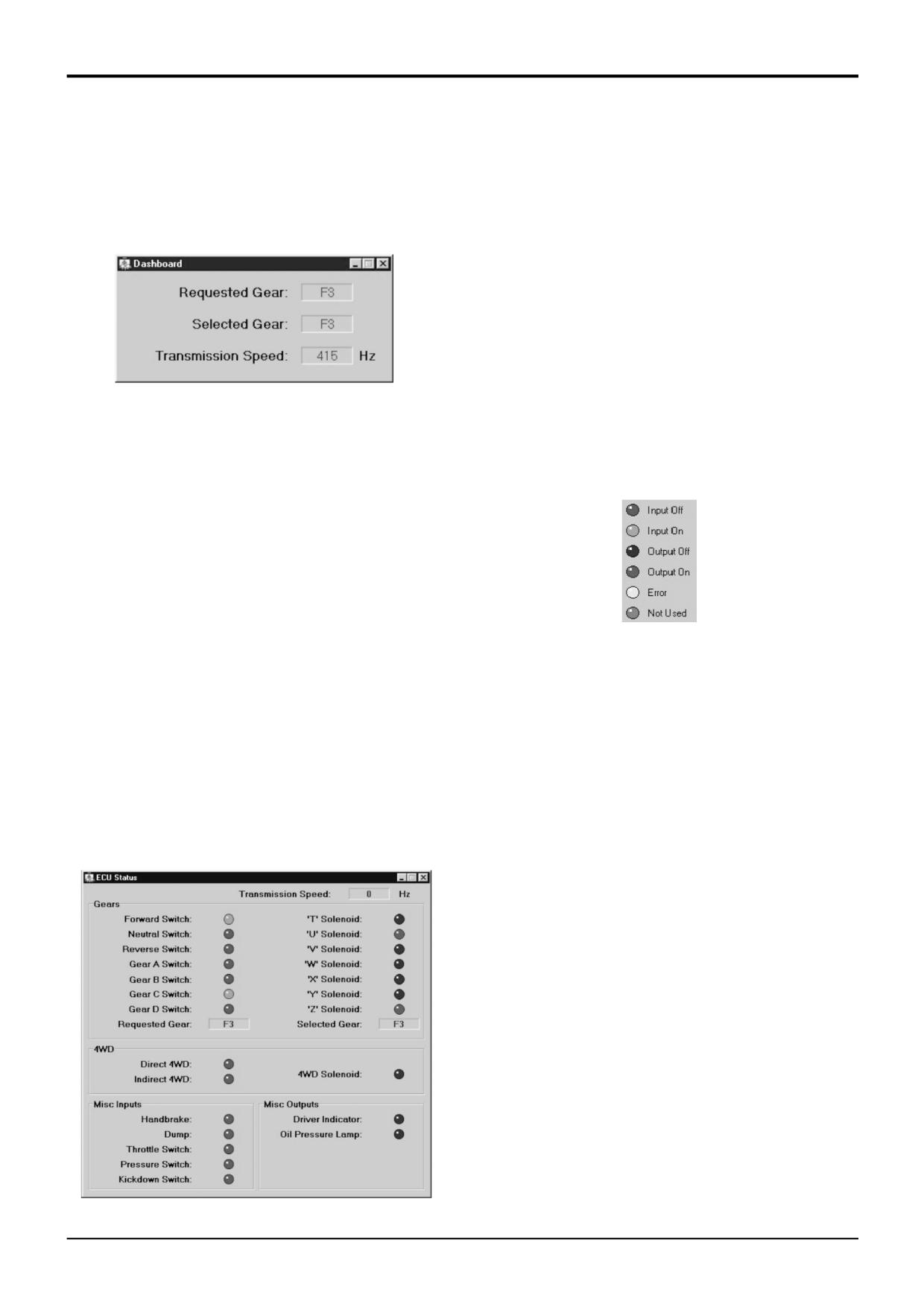
11. Dashboard
This offers a simple uncluttered display showing;
Information in this display is constantly updated in real-time.
(Some older PCs may experience a slight delay in updating
this page, but usually only less than one second.)
The left hand side shows the inputs to the ECU, their status
indicated by green LEDs.
The right hand side shows the outputs from the ECU, their
status shown by red LEDs.
S404460
Requested Gear
The exact colour of the LED indicates the status of that
This is the demand from the driver.
feature.
Selected Gear
A key in the bottom left corner of the main window explains
This is the actual gear being selected by the ECU.
the colours.
Note: The driver Request Gear is not always the same as
the Selected Gear, e.g. when the ECU blocks shifts when
offering protection.
Transmission Speed
This is the current transmission output speed which is
directly related to the road speed (through axle ratio and tyre
size). The transmission speed sensor is located next to the
S404480
output gear and detects the passing of the gear teeth. The
sensor has a fixed installation, no adjustment is necessary.
The following is a brief explanation of each feature. For
further information and examples of typical scenarios please
The Transmission Speed value is a frequency reading and is
refer to the accompanying Fault Finding Guide accessible
displayed in Hertz (Hz), or teeth per second.
via the Help menu.
This signal is used by the ECU to determine gear-shifting
Transmission Speed
and protection strategies.
This is exactly the same signal as explained in the previous
section.
12. ECU Status Page
Gears
This page gives a detailed picture of how the ECU is
Inputs: The items on the left show the signal lines
operating.
connected to the gear selection lever. This lever if the left
hand half of the control lever assembly mounted on the
steering column.
Outputs: The items on the right are the power signals going
down to the transmission solenoid valves. The LEDs will
indicate which solenoids are being energised. Error
detection on the output electrics is continually running. If any
output were to develop a fault (e.g. open circuit or short
circuit) then the LED will turn yellow. Fix the fault and the
LED will revert back to red.
During certain gear-shifts the ShiftMaster ECU will perform
electrical Modulation to improve gear-shift quality. The ECU
does this by adding delays to off-going and/or on-coming
clutches and so overlapping energised outputs. These
delays are in the order of a few hundred milli-seconds but it
is sometimes long enough to be observed on the status
LEDs. Thus, during certain shifts it is quite normal to observe
more than 2 outputs ON at any one time.
S404470
9803/3280
Issue 1
Section F
Transmission
Section F
69 - 9
Service Procedures
69 - 9
Powershift Gearbox - 6 speed
ShiftMaster Diagnostics - User Guide
4WD
13. General Information
The machine driver has 2 inputs which are used to influence
the state of the 4WD solenoid output. These features
For all enquiries about the ShiftMaster Diagnostics tool
interact as follows;
please follow your normal channels of enquiry. This ensures
that useful information can filter through to JCB Service
Firstly there is a Direct 4WD input which is, in general,
personnel at all levels.
connected to the machine footbrake switch (which in turn
controls the brake lights). Whenever this signal is present the
4WD Solenoid output is energised.
The second input is Indirect 4WD which is usually derived
from a command from a console mounted '4WD selector'
switch. (However, this switch arrangement may change
between machines.) If the transmission speed is too high
then the ECU will over-ride this signal and automatically
disengage the 4WD.
Misc. Inputs
These inputs are derived from the remaining driver controls.
A brief summary follows but refer to the Fault Finding Guide
for full details.
Handbrake Switch: Signal derived from the Parkbrake
switch. Used to hold the transmission in Neutral if the
parkbrake is applied.
Dump Switch (or Transmission Disconnect): Signal usually
derived from a momentary switch fitted to a loader lever.
Temporarily selects Neutral when pressed (usually to divert
engine power to hydraulics).
Throttle Switch: Dedicated switch fitted to the machines'
accelerator pedal. Used to interact with the Automatic Mode
of gear-shifting.
Pressure Switch: Signal is derived from the transmission
mounted Low Oil Pressure Switch.
Kickdown Switch: Another momentary button (mounted on
the cab floor) used to temporarily select the next lowest
gear.
Misc. Outputs
These are the additional ECU outputs, generally used to
control cab instrumentation like the low Oil Pressure Lamp
and Driver Indicator (lamp and buzzer where fitted).
9803/3280
Issue 1
Section F
Transmission
Section F
70 - 1
Service Procedures
70 - 1
Powershift Gearbox - 6 speed
ShiftMaster Diagnostics - Troubleshooting Guide
1. Introduction
2. Elementary Checks
If you are experiencing difficulties with getting ShiftMaster
Please make sure that the correct communications leads are
Diagnostics and your PC to communicate with a
being used and are not damaged in any way.
ShiftMaster ECU then please take a little time to read the
following information which has been compiled to guide
Non Communication with DLA
diagnosis of such problems.
In general, whenever there are problems communicating
with the DLA there will be an error message displayed.
To utilise any supporting ShiftMaster Service Tools requires
the use of the JCB Data Link Adaptor (DLA) which is part of
the standard JCB Electronic Service Tool Kit, part number
892/01033.
This software is intended for use on IBM Compatible
Personal Computers (PCs) running Windows 9x or
Windows2000 operating systems but is not compatible with
either earlier versions of Windows 3.x.
S404140
It is known that some laptop PCs can experience problems
More specifically, if communications can not be established
with serial communications.
with the DLA then the ECU Setup Page will display 'NO DLA
COMMS' where the ECU Part Number should be.
In a few rare cases the PCs hardware does not allow the
diagnostics software access to communications (COM)
ports.
JCB Service are in the process of compiling a
'recommended' list of laptops which we know to work
satisfactorily with JCB Software.
In the majority of cases conflicts are caused by either
S404150
software already running on the PC, or by certain 'driver'
Non Communication with ECU
files which hog the COM port(s).
If communications can not be established with the ECU then
the ECU Setup Page will display 'NO ECU COMMS' where
Note: a PC which has many users and uses is likely to
the ECU Part Number should be.
contain some redundant software and drivers.
If you do not feel technically competent to adjust PC
software & set-up, please enlist the help of someone
suitably trained before proceding.
S404160
Note: The ECU must be powered for communications to
work, i.e. the machine ignition must be ON (but the engine
need not be running).
9803/3280
Issue 1
Section F
Transmission
Section F
70 - 2
Service Procedures
70 - 2
Powershift Gearbox - 6 speed
ShiftMaster Diagnostics - Troubleshooting Guide
3. DLA Drivers
5. IR Drivers
The DLA has software 'drivers' (i.e. programs which handle
Many Laptop PCs have a built in InfraRed (IR)
communications) programmed into the unit. There are
communications port. There is likely to be some resident
matching drivers that must also be resident on you PC.
software to control this port. If this type of port is present,
but never used, then try disabling the driver;
The update of both these sets of drivers is handled by JCB
Service Master. Please refer to the applicable supporting
System Properties > Device Manager > Ports >
(infrared)
literature.
6. Modem Drivers
4. PC Power Management
Check that only the correct modems are installed on the
Some laptops' Power Management software can disrupt the
machine.
COM ports.
Experience has shown that multi-user PCs often contain
This problem occurs with many other software applications
many modems, perhaps installed for use other than in the
and is not unique to JCB Service Master applications. The
office.
following advice is worth bearing in mind.
Disable any unused modems.
If the user experiences communications problems with a
ShiftMaster ECU turn OFF the laptops' power management
There has been no experience of correctly installed internal
software.
modems or PCMCIA cards (modem or network) causing
significant problems.
Problems may be;
(a) Complete failure to establish communications with an
ECU.
7. Windows XP & Windows NT
(b) A drop-out of communications (i.e. connects to the
Please note the ShiftMaster Diagnostics software is NOT
ECU and after a while the link fails).
designed to run on Windows NT. In addition JCB can not
(c) Intermittent failure (i.e. seems to disconnect and re-
guarantee that this software will be fully functional with the
connect at random intervals).
latest versions of Windows (e.g. WindowsXP) although JCB
are continually developing support for different operating
Item (a) is probably the most common.
systems.
To turn OFF the laptops power management open Windows
Control Panel (Start > Settings > Control Panel). There will
8. Further Assistance
normally be an icon to run that particular laptops' power
If a communication problem persists, then the following
management software. Turn OFF the power management,
contacts may be able to provide further assistance;
close the tool and then close the control panel.
a). If applicable, try seeking assistance from your
These power management tools are specific to the laptop.
Computer Systems Engineer/Technician.
Some may require the PC to be re-booted before the
changes take effect.
b). The first port of call outside your company should be
the laptop machine dealer or agent.
c). Your next enquiries should be with the laptop machine
OEM (Original Equipmemt Manufacturer). If the OEM is
unable to assist they will make the relevant enquires on
your behalf.
If you continue to have a communications problem, note
the applicable laptop make and model. Contact JCB
Service so that further investigations can be made..
For all enquiries about the ShiftMaster Diagnostics tool
please follow your normal channels of enquiry. This ensures
that useful information can filter through to JCB Service
personnel at all levels.
9803/3280
Issue 1
Section F
Transmission
Section F
75 - 1
Propshafts
75 - 1
Propshafts
Removing and Replacing
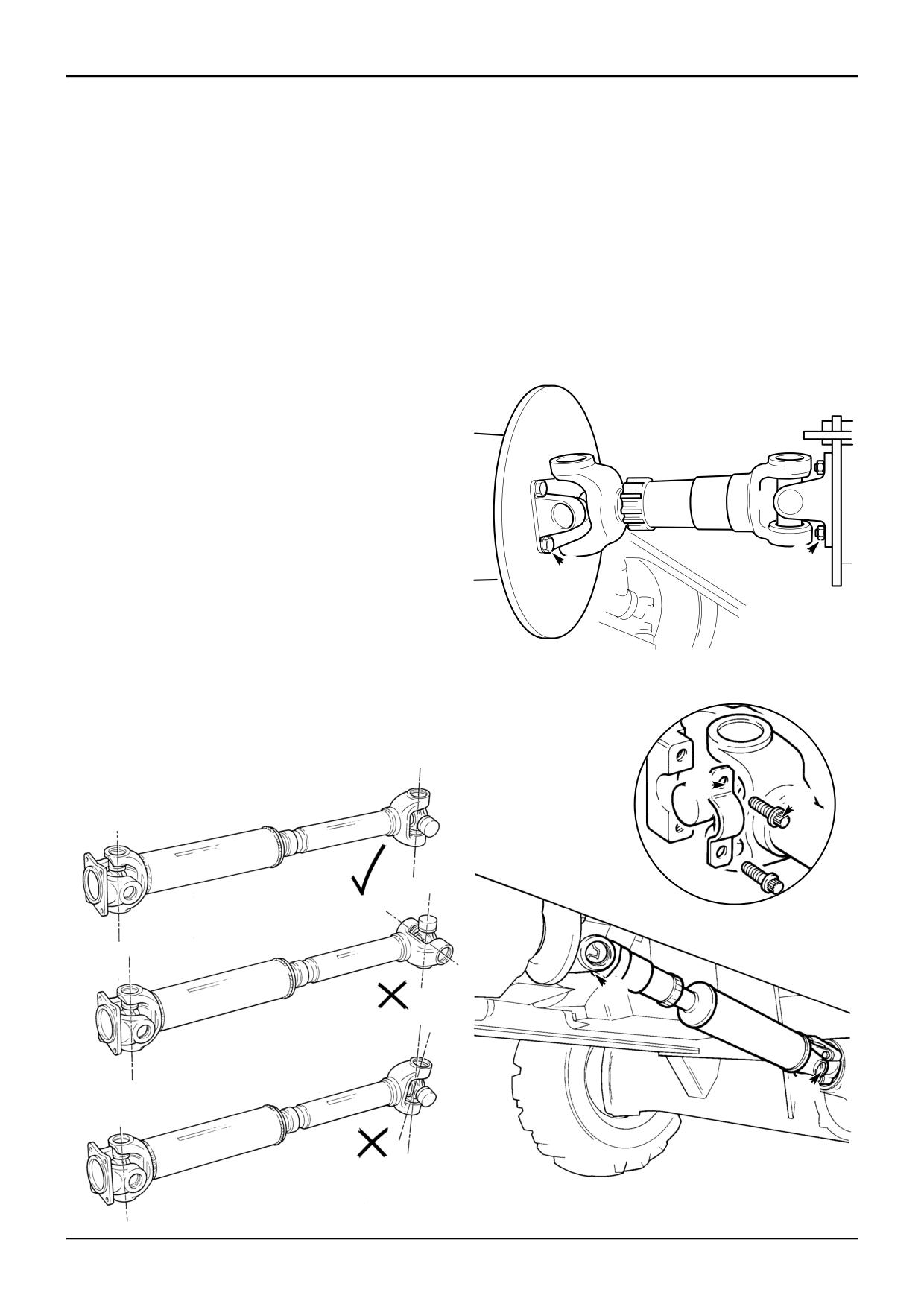
When Removing
Before removing propshafts always mark both companion
flanges and also mark the sliding joints prior to removal.
When Replacing
Upon reassembly, after lubricating sliding joints with JCB
MPL Grease, align the shafts against identification marks
previously made or, in the case of a shaft being renewed,
REAR
use the manufacturer's alignment markings.
Apply JCB Threadlocker and Sealer to threads of all flange
bolts.
Retaining straps C stretch with use, therefore these straps
must always be replaced with new ones.
The propshaft must have both ends exactly on the same
plane as shown at X. The yokes must not be at right angles
as at Y or at an intermediate angle as at Z.
B
Torque Settings
A
Item
Nm
kgf m
lbf ft
A
75 - 85
7.7 - 8.7
55 - 63
B
118
12
87
A396840
C
A
X
S232350
Y
A
A
Z
S157500
S189610
FRONT
9803/3280
Issue 1
Section F
Transmission
Section F
80 - 1
Front Axle - SD55, SD70
80 - 1
Removal and Replacement
K
C
-238.14
A
J
J
C
D
B
H
F
B
E
G
A401290
9803/3280
Issue 1
Section F
Transmission
Section F
80 - 2
Front Axle - SD55, SD70
80 - 2
Removal and Replacement (cont’d)
Note: The following procedure can be applied to both AWS
and 2WS machines. Dis-regard information not applicable to
your machine type, for instance, 2 wheel steer machines will
not have steering proximity switches fitted.
! WARNING
A raised and badly supported machine can fall on you.
Position the machine on a firm, level surface before
raising one end. Ensure the other end is securely
chocked. Do not rely solely on the machine hydraulics or
jacks to support the machine when working under it.
Disconnect the battery, to prevent the engine being
started while you are beneath the machine.
GEN 1-1
Removal
! WARNING
Raised loader arms can drop suddenly and cause
serious injury. Before working under raised loader arms,
fit the loader arm safety strut.
GEN 3-2
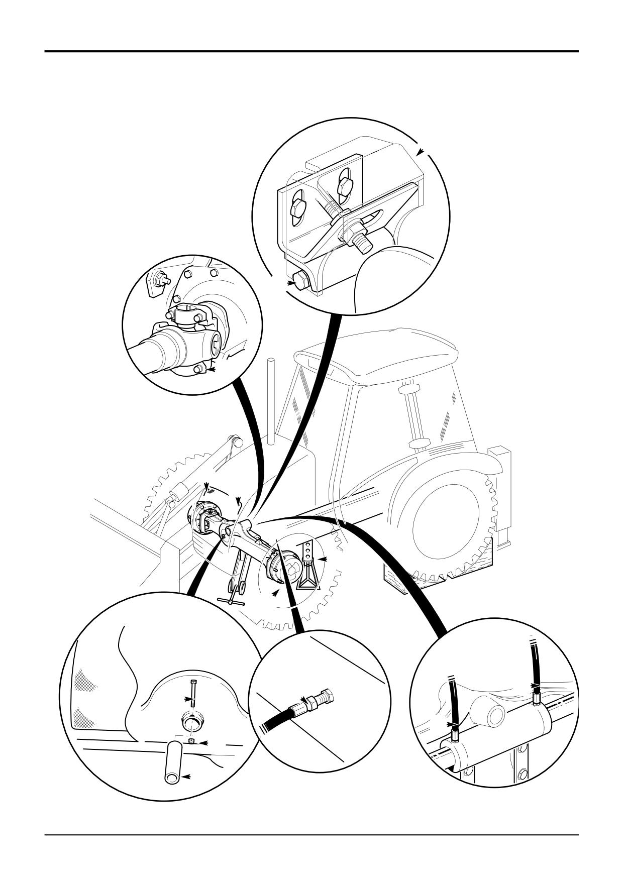
1
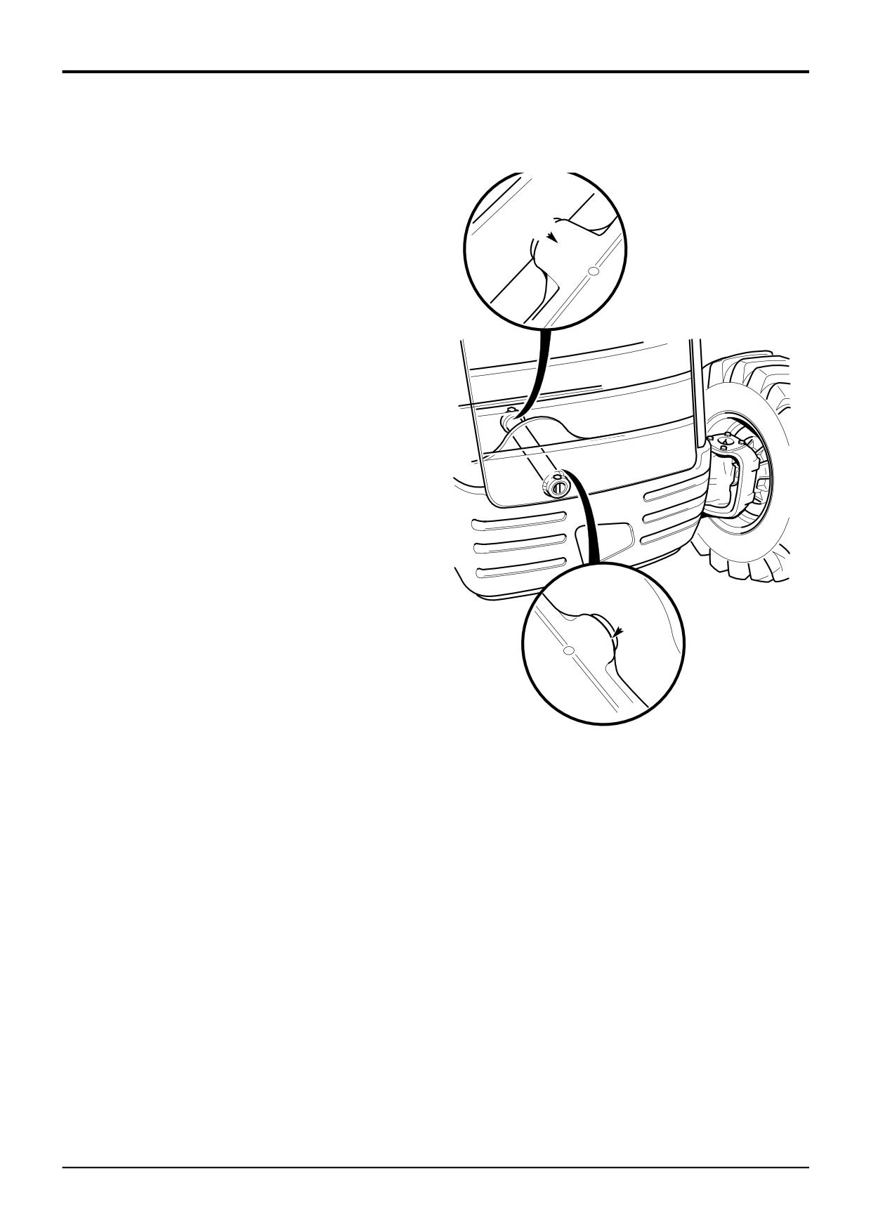
Release screws J and remove the front grille.
2
Remove the cover K from the proximity switch and then
remove the bracket and switch assembly.
3
Using tool 892/00822 remove bolts A to disconnect the
drive shaft from the axle.
4
Disconnect the hydraulic pipes B from the steer rams,
blank off all exposed connections.
5
Disconnect remote grease nipple hose H.
6
Loosen the road wheel retaining nuts D.
7
Make sure that the rear wheels are blocked, use the
loader arms to raise the front end of the machine.
8
Prop the machine on each side as shown at C.
9
Remove the front road wheels.
10
Position a jack underneath the balance point (see Note)
of the axle and support the axle weight.
Note: Because the drivehead assembly is offset, the balance
point of the axle is not the centre of the axle. Attach a
'cradle' to the jack that will partially embrace the axle.
11
Remove nut E and pivot pin retaining bolt F.
12
Remove pivot pin G seals, use puller (tool no.
993/68100) and remove the pivot pin G and axle shims.
13
Lower the jack so that the axle is clear of the mounting
yoke and remove the axle.
9803/3280
Issue 1
Section F
Transmission
Section F
80 - 3
Front Axle - SD55, SD70
80 - 3
Removal and Replacement (cont’d)
Replacement
Replacement is the reverse of the removal sequence.
! WARNING
Y
If, for whatever reason, a wheel stud is renewed, all the
studs for that wheel must be changed as a set, since the
remaining studs may have been damaged.
2-3-2-8
Whenever a wheel has been removed, check the wheel nut
torques every two hours until they stay correct.
Apply JCB Lock & Seal to the threads of bolts A.
The front axle must be shimmed to give a maximum fore and
aft movement of 0.5 mm (0.020 in).
Nylon shims must be fitted as follows:
AWS Machines
a Fit a 5.0 mm thick master shim (coloured blue) between
the front of the axle and the yoke plate as shown at X.
b Measure the fore and aft movement and subtract 0.5
mm to obtain the required shim thickness. Fit the
correct thickness shim between the rear of the axle and
the yoke plate as shown at Y.
X
2WS Machines
a Fit a 5.0 mm thick master shim (coloured blue) between
the rear of the axle and the yoke plate as shown at Y.
A258180
b Measure the fore and aft movement and subtract 0.5
mm to obtain the required shim thickness. Fit the
correct thickness shim between the front of the axle
and the yoke plate as shown at X.
Note 1: DO NOT fit more than 2 shims (including the master
shim).
Note 2: To assist assembly, use the double sided tape ring
supplied to retain the shims on the yoke plate.
If the setting of the steering proximity switch has been
disturbed, then complete the front axle proximity switch
setting procedure, see Section H, Service Procedures.
Torque Settings
Item
Nm
kgf m
lbf ft
A
79
8
58
D
680
69
500
9803/3280
Issue 1
Section F
Transmission
Section F
81 - 1
Front Axle - SD55, SD70
81 - 1
Hub and Driveshaft - Dismantling
The following illustrations show the axle removed from the machine but the hubs may be dismantled without removing the
axle.
! WARNING
A raised and badly supported machine can fall on you.
Position the machine on a firm, level surface before
raising one end. Ensure the other end is securely
chocked. Do not rely solely on the machine hydraulics or
jacks to support the machine when working under it.
Disconnect the battery, to prevent the engine being
started while you are beneath the machine.
GEN 1-1
1
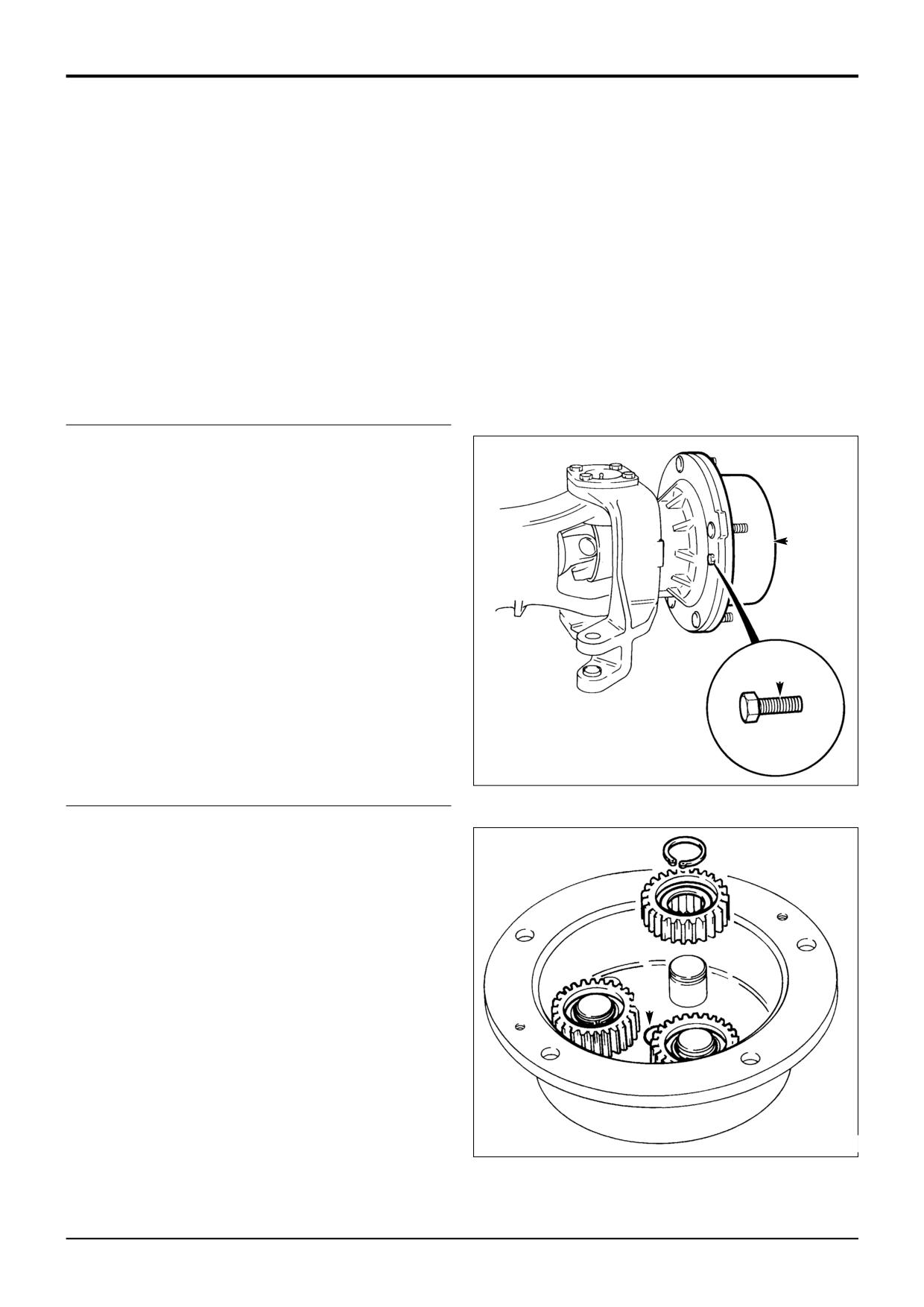
Disconnect the steering track rod. Drain oil from the
hub.
Note: The illustration shows a typical axle.
2
Remove screws A.
B
3
Lever the planet gear carrier B off the bearing carrier.
Clean off all traces of sealant from the mating faces or
remove ‘O’ ring as applicable.
A
S258220
4
Remove planet gears only if defective. Note that gears
can only be removed as assemblies, which comprise
the gear, the bearing and two 'L' shaped circlips. To
remove a planet gear, first remove the external circlip.
5
Pull off the planet gear.
6
The driveshaft thrust pad C is drilled and tapped M6 for
removal purposes.
C
255920
9803/3280
Issue 1
Section F
Transmission
Section F
81 - 2
Front Axle - SD55, SD70
81 - 2
Hub and Driveshaft - Dismantling (cont'd)
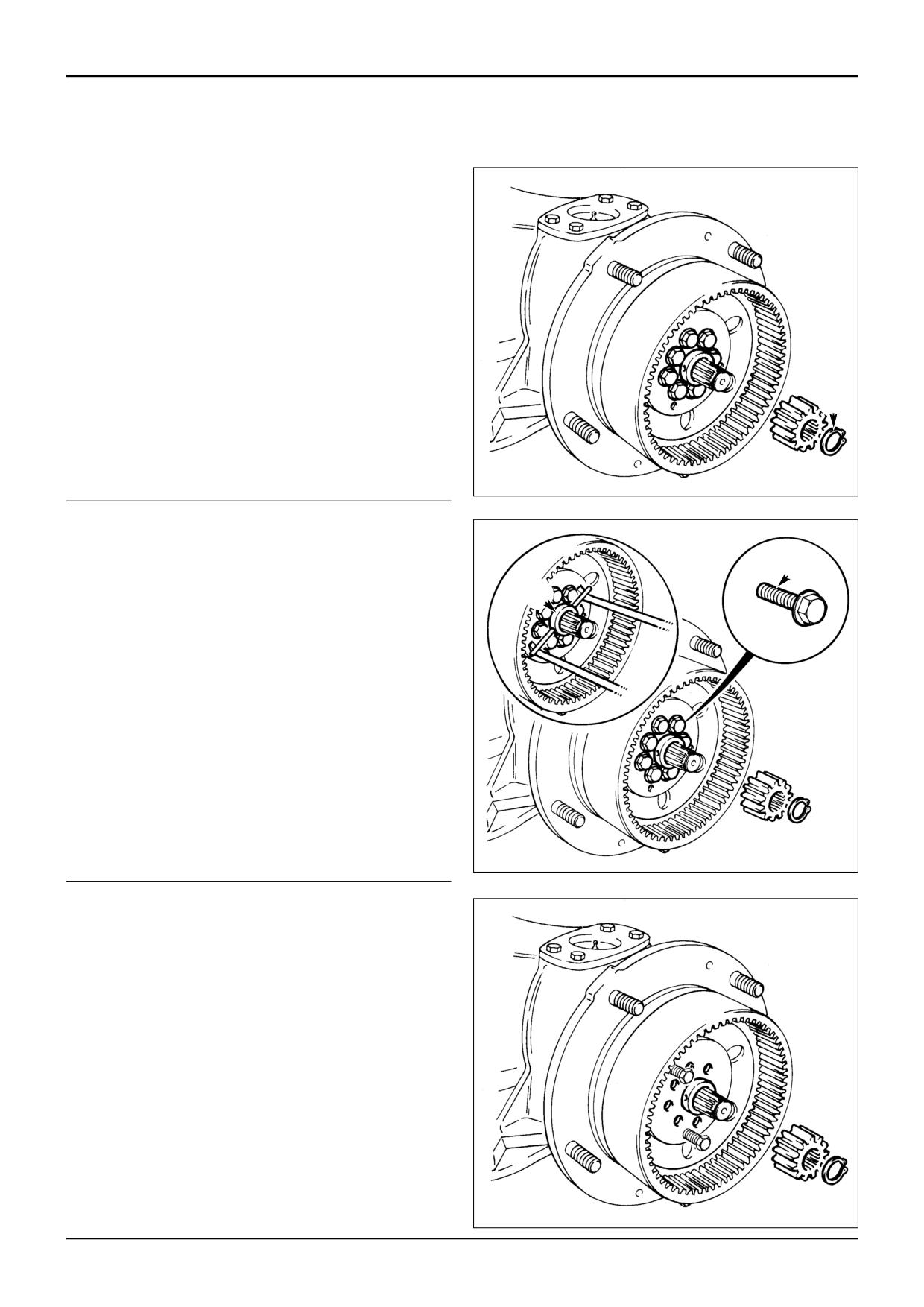
7
Remove circlip D to allow the sun gear to be slid off the
drive shaft.
D
256010
8
To remove the ‘Verbus Ripp’ bolts E, it is necessary to
remove the spacer F. Revolve the spacer with a suitable
drift to align the holes in the spacer with the space
between the bolts.
E
F
9
Using two dowels and two heel bars, remove the spacer
using the method shown.
10
Remove the 'Verbus Ripp' bolts using a special tool
(part number 892/00333). These bolts are very tight and
care must be taken not to distort the bolt heads. Use as
short an extension bar as possible.
255930
11
Using 2 high grade M14 bolts as jacking screws,
remove the annulus carrier.
Note: Fretting between the hub swivel and annulus carrier
mating faces might be evident; this condition is normal, do
not attempt to repair. If the hub swivel and annulus carrier
are to be re-used, the carrier must be assembled in the same
angular position it was removed; match mark the hub swivel
and carrier before removing the carrier.
S258240
9803/3280
Issue 1
Section F
Transmission
Section F
81 - 3
Front Axle - SD55, SD70
81 - 3
Hub and Driveshaft - Dismantling (cont'd)
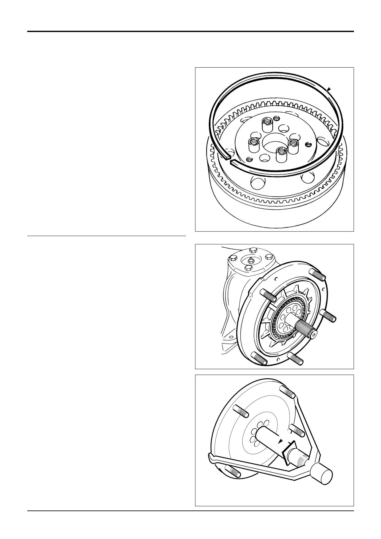
12
Remove circlip G to separate the annulus ring from the
annulus carrier.
G
S248910
13
Pull off the bearing carrier together with the outer
bearing cone and its bearing cup. Withdraw the inner
bearing cup from the inboard side of the carrier.
Note: To prevent damaging the axle case inner seal, do not
lever against the half shaft. Place a tube over the half shaft
and lever against the tube, as shown at X.
S248920
X
A258390
9803/3280
Issue 1
Section F
Transmission
Section F
81 - 4
Front Axle - SD55, SD70
81 - 4
Hub and Driveshaft - Dismantling (cont'd)
14
Pull off the inner bearing - see Note at step 13.
15
Remove and discard the seal.
Note: The inner bearing and oil seal may withdraw with the
bearing carrier.
S258260
16
Remove and discard the combination seal. When
assembling the axle, a new combination seal must be
used.
S248880
17
Mark position of top and bottom trunnions H and
remove. Withdraw the hub carrier.
H
Note 1: Trunnions may be removed easily by pumping
grease through the grease nipple.
S248890
H
18
Use adaptor 993/59500 with slide hammer tool
892/00224 and remove driveshaft seal and needle roller
bearing from the hub carrier.
S161460
9803/3280
Issue 1
Section F
Transmission
Section F
81 - 5
Front Axle - SD55, SD70
81 - 5
Hub and Driveshaft - Dismantling (cont'd)
19
Use a puller to remove the trunnion seal and bearing.
S258270
20
Withdraw drive shaft.
21
Prise out drive shaft inner oil seal J.
22
Remove circlip K
23
Remove bearing using tool 892/00225.
K
J
255990
9803/3280
Issue 1
Section F
Transmission
Section F
81 - 6
Front Axle - SD55, SD70
81 - 6
Hub and Driveshaft - Assembly
1
Tap drive shaft inner bearing into position and secure
with circlip K.
2
Fit new oil seal J. Pack grease between lips of seal.
3
Fit drive shaft, taking care to locate inner end into
splines of differential gears.
K
J
255990
4
Press new trunnion oil seal into position followed by the
bearing. Grease bearing and oil seal before fitting to
axle.
S258270
5
Fit driveshaft needle roller bearing to the hub carrier.
Pack the cavity between the oil seal lips with grease
and then fit the seal.
S161460
9803/3280
Issue 1
Section F
Transmission
Section F
81 - 7
Front Axle - SD55, SD70
81 - 7
Hub and Driveshaft - Assembly (cont'd)
6
Locate hub carrier and fit bottom trunnion. Apply JCB
Lock and Seal (part no. 4101/0202) to the bottom
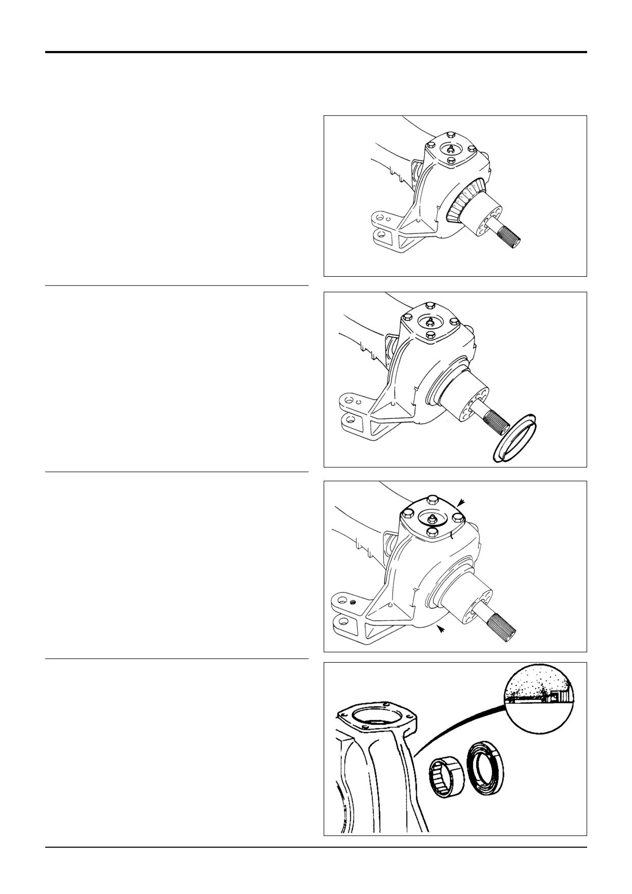
trunnion bolt threads, fit and tighten to 98Nm (72 lbf ft).
Fit top trunnion and leave top trunnion bolts finger tight.
S248890
7
Attach a spring balance to track rod swivel as shown
and note the reading. Tighten the top trunnion bolts to
eliminate end float but no bearing pre-load, ie no
increase in spring balance reading.
8
Refit top trunnion. Apply JCB Threadlocker and Sealer
to the top trunnion bolt threads, fit and tighten to 98 Nm
(72 lbf ft). Check spring balance reading which should
be 4.5 kgf (10 lbf) more than the reading recorded at fig.
7.
S248850
9
Lightly oil the inner wheel bearing. Assemble the inner
A267170
and outer bearing cups, and the inner bearing cone into
the bearing carrier.
A
10
Fit a new combination oil seal. Do not lubricate before
fitting. Drive the seal squarely into the carrier until the
locating lip is flush as shown at A.
11
Fit the bearing carrier onto the axle arm. Lightly oil the
outer wheel bearing race. Fit the bearing onto the axle
arm. Rotate the bearing during fitting.
S248920
9803/3280
Issue 1
Section F
Transmission
Section F
81 - 8
Front Axle - SD55, SD70
81 - 8
Hub and Driveshaft - Assembly (cont'd)
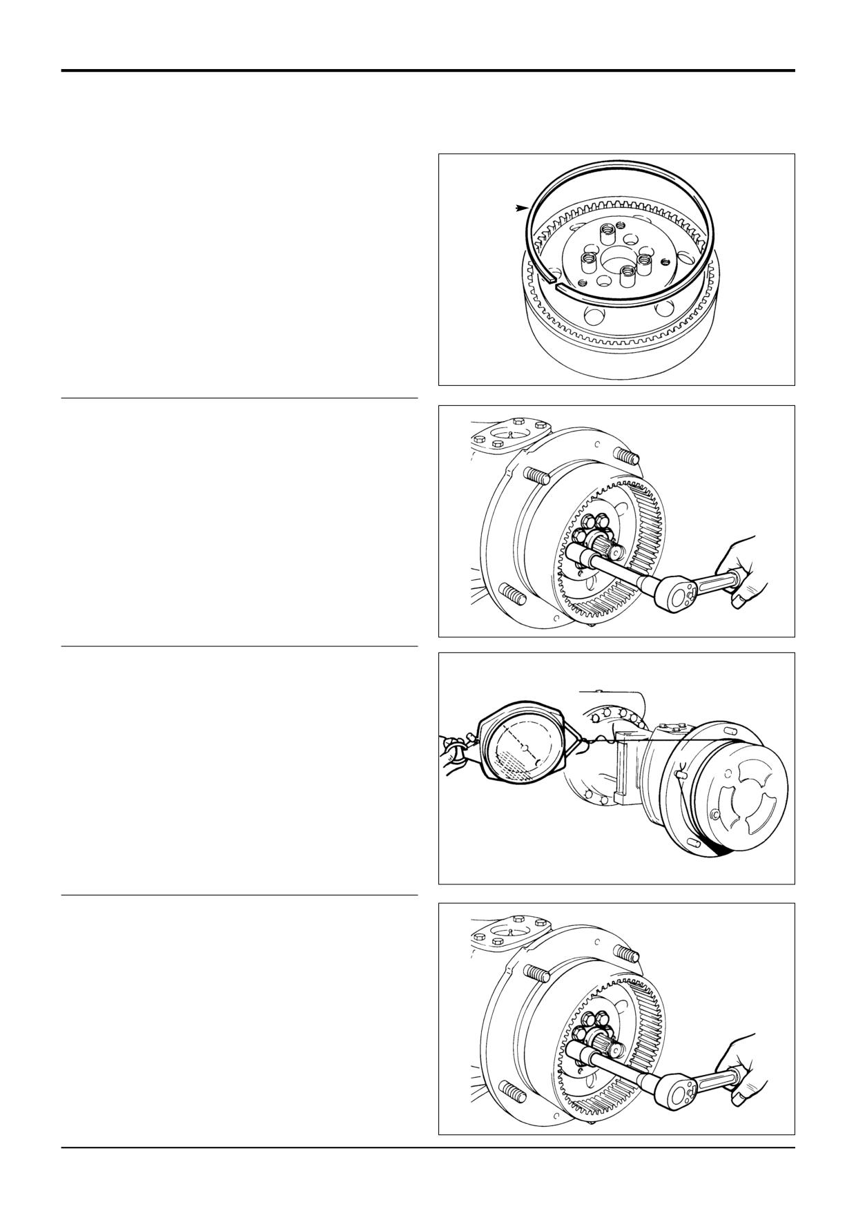
12
Assemble the annulus ring to the annulus carrier.
Secure with the circlip G.
G
S248910
13
Fit annulus assembly in the same angular position as
removal (see Note, Dismantling, step 11) using new
'Verbus Ripp' bolts. Do not fully tighten bolts but allow
the bearing carrier to rock slightly. Measure seal drag
rolling force - see step 14.
Note: Steps 13 to 16 describe measurement of rolling force.
To measure rolling torque (simplified process), a special tool
is required. Refer to Service Tools.
S248540
14
To measure seal drag rolling force:
-
Refit the planet gear carrier - DO NOT FIT THE SUN
GEAR.
-
Use a spring balance and cord wrapped around the
planet carrier flange as shown.
-
Pull the spring balance so that the hub rotates, do
several times to let the seal bed in and record the
reading.
-
Remove planet gear carrier.
S248870
15
Tighten M14 Verbus Ripp bolts to 320 Nm (236 lbf ft, 33
kgf m) and then measure rolling force - see step 16.
S248540
9803/3280
Issue 1
Section F
Transmission
Section F
81 - 9
Front Axle - SD55, SD70
81 - 9
Hub and Driveshaft - Assembly (cont'd)
16
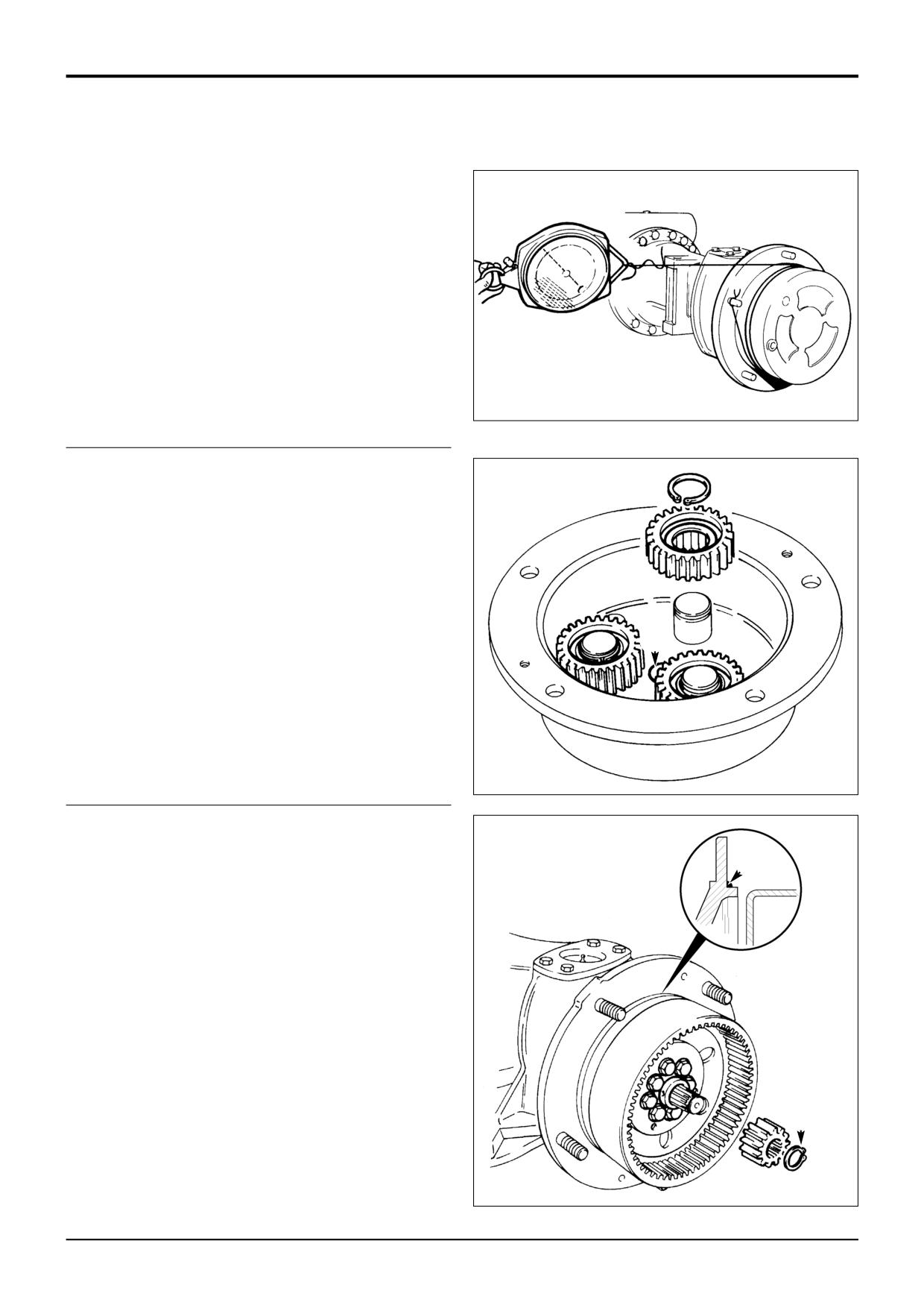
To measure rolling force:
-
Refit the planet gear carrier - DO NOT FIT THE SUN
GEAR. Use a spring balance and cord wrapped
around the planet gear carrier flange as shown. Pull
the spring balance so that the hub rotates and
record the reading.
-
To get the rolling force, subtract seal drag rolling
force (see step 14) from reading obtained at this
step, the result should be 64 to 117 N (14 to 26 lbf).
-
If the resulting figure is outside these limits check:
the seal is fitted correctly; and/or renew bearings if
necessary; and /or new fitted components.
S248870
-
Remove planet gear carrier.
17
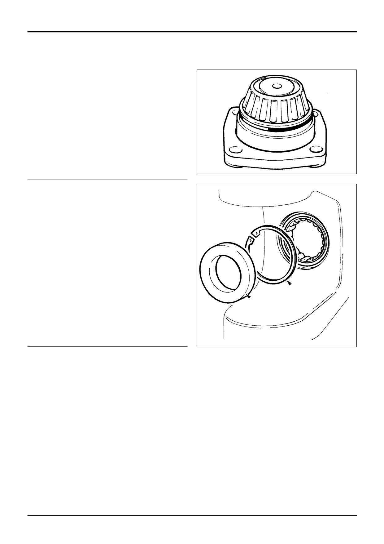
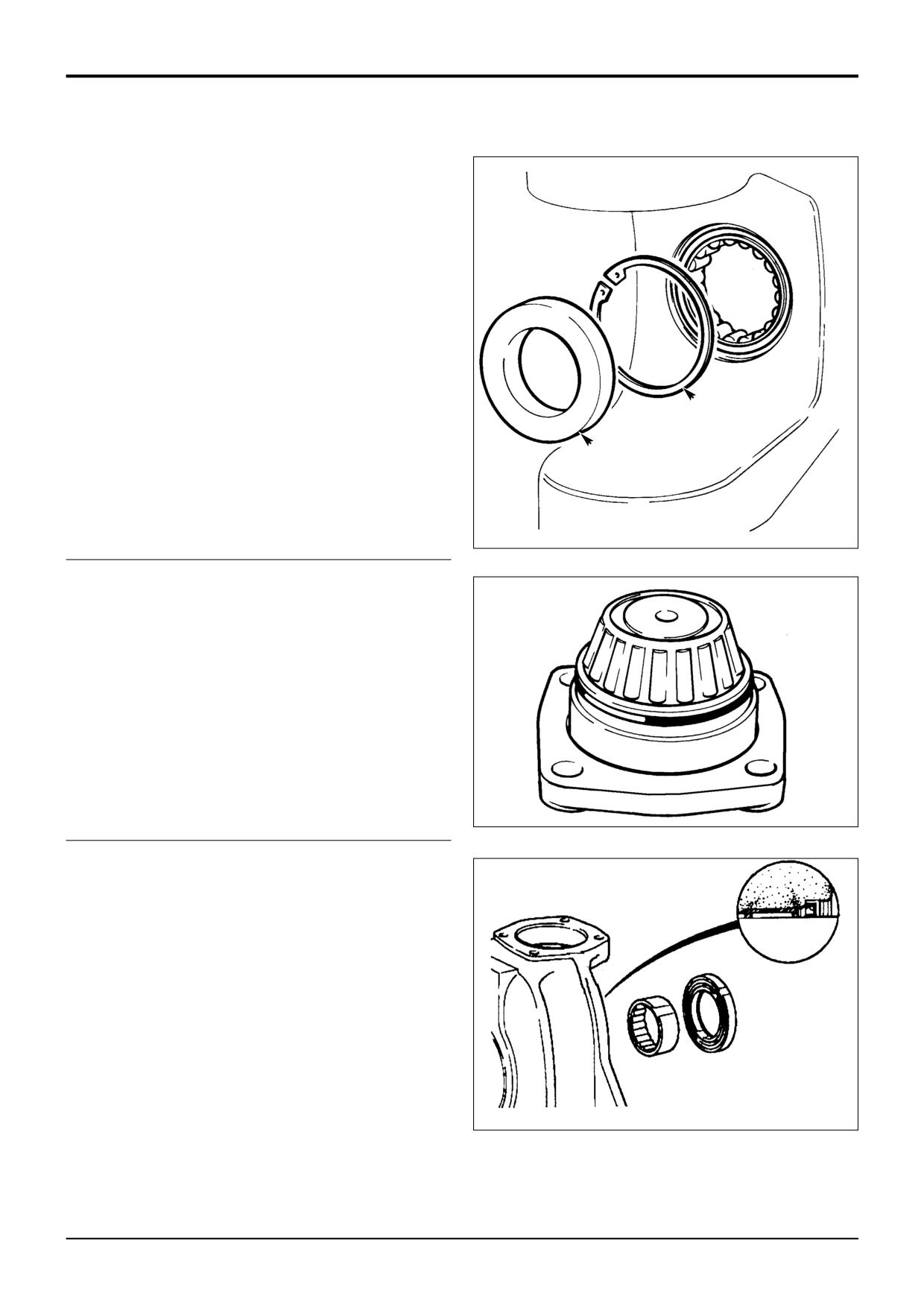
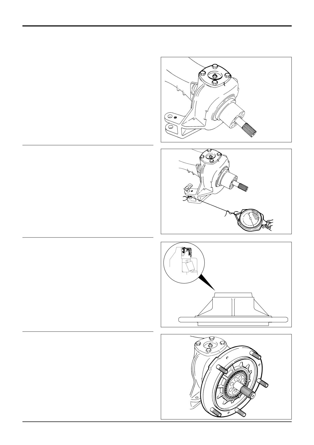
Press the drive shaft thrust pad C (chamfered side
lowermost) into the recess in the planet carrier.
18
Fit new planet gears in place of any that were removed.
(See step 4 in 'Dismantling'). Secure with circlip.
Note: Make sure that the SMALL radius on the gear bearing
internal diameter is facing uppermost, that is at the circlip
end of the planet pin.
C
255920
19
Fit spacer and slide the sun wheel onto the driveshaft
and secure with circlip D. Apply a fillet of sealant
4102/0900 evenly around the bearing carrier as shown
X
at X.
Note: Some machines may have an ‘O’ ring instead of
sealant - where appropriate fit a new ‘O’ ring.
Note: The sun gear must be fitted with the 1.5 mm (0.060 in)
x 45° chamfer inboard.
D
S258230
9803/3280
Issue 1
Section F
Transmission
Section F
81 - 10
Front Axle - SD55, SD70
81 - 10
Hub and Driveshaft - Assembly (cont'd)
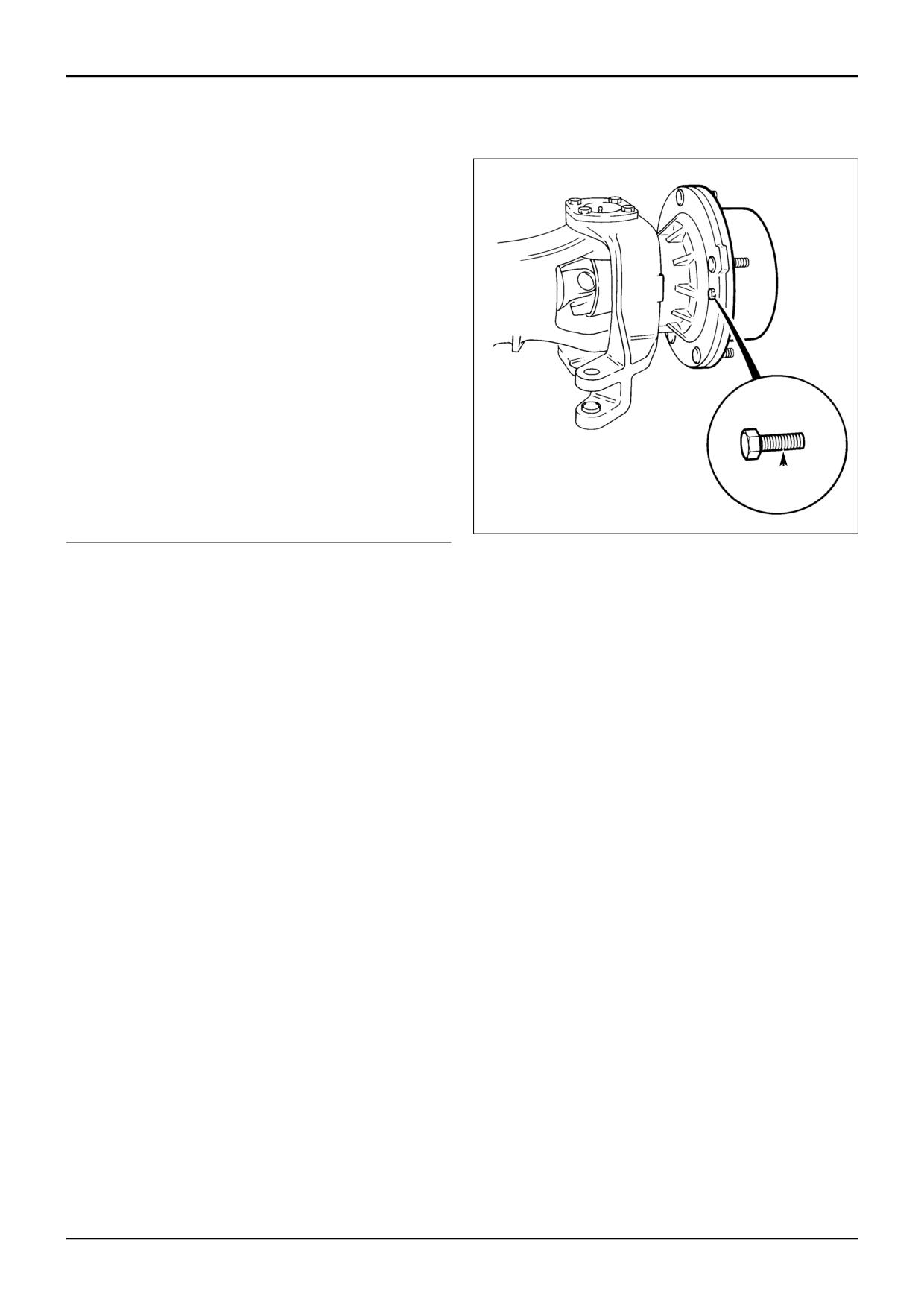
20
Fit the planet carrier onto the bearing carrier, ensuring
that the two tapped holes are in line with those on the
bearing carrier. Fit and torque tighten screws A to
56Nm (41Ibf ft; 5.7kgf m) after applying JCB Lock and
Seal to the threads.
Note: Do not strike the centre of the planet gear carrier when
fitting as this may dislodge the driveshaft thrust pad fitted at
step 17.
Re-fill hubs with the correct grade oil.
A
S258220
9803/3280
Issue 1
Section F
Transmission
Section F
82 - 1
Front Axle - SD55
82 - 1
Drive Head - Dismantling
ITL00670
9803/3280
Issue 1
Section F
Transmission
Section F
82 - 2
Front Axle - SD55
82 - 2
Drive Head - Dismantling (cont’d)
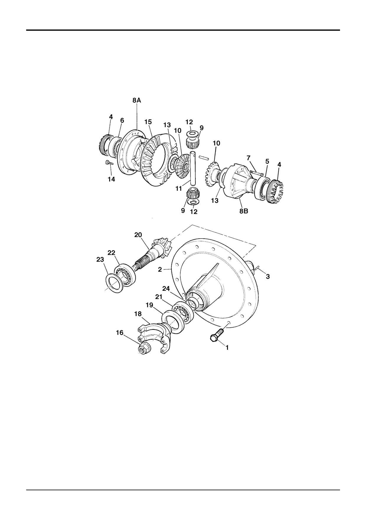
1
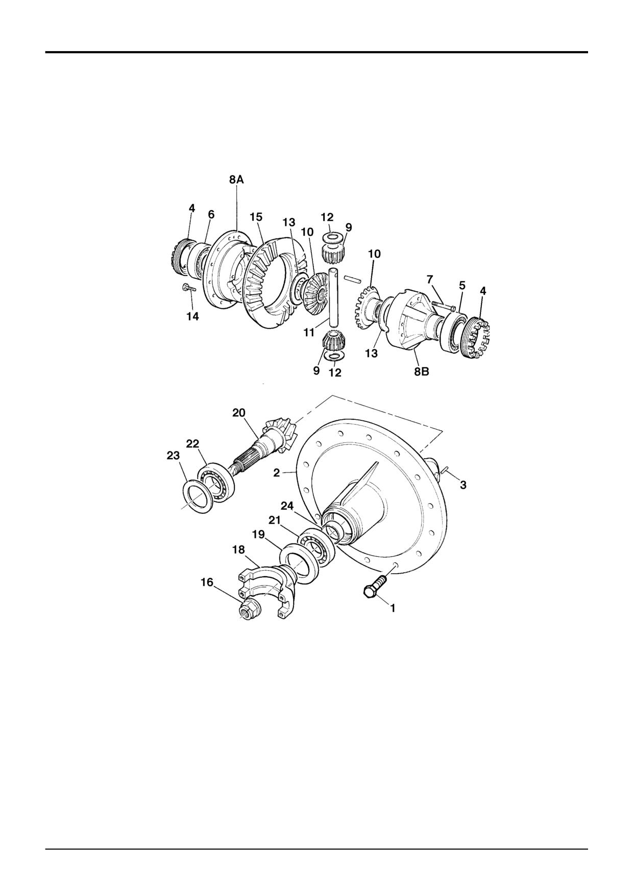
Drain the oil from the drive head. Remove the propshaft.
2
To remove the drive head it is necessary to withdraw
both drive shafts from the axle.
3
Remove the drive head carrier screws 1. Mark the
installation position of drive head carrier 2 relative to the
axle housing.
4
Remove the drive head carrier from the axle housing.
5
Pull out the roll pins 3 and remove the castellated nuts
4. Remove the outer races of bearings 5 and 6 from the
drive head carrier bores.
6
Remove inner bearing races of 5 and 6.
7
Remove differential assembly 8 from carrier.
8
Loosen the differential case half bolts 7 and pull the
case halves 8A and 8B apart. Remove the axle bevel
gears 9, the differential bevel gears 10, trunnion pin 11
and thrust washers 12 from the case halves.
9
Remove the thrust washers 13 from both case halves.
10
Pull off the bearing 6 from case half 8A.
11
Remove the Verbus Ripp bolts 14 and separate the
crownwheel 15 from the case half 8A.
12
Remove pinion nut 16. Use Service Tool 892/00812 to
prevent drive yoke 18 from rotating.
13
Mark the position of the drive yoke on the splined shaft.
Remove the drive yoke.
14
Drive pinion shaft 20 out of drive head carrier 2.
15
Prise shaft seal 19 out of the bore.
16
Remove taper roller bearing 21 and tap out the outer
bearing race.
17
Tap out the outer race of bearing 22 from the opposite
bearing housing and remove the drive pinion shim(s) 23.
18
Remove spacer 24 from drive pinion 20. Prise taper
roller bearing 22 to raise it sufficiently to insert bearing
pullers. Pull the bearing from the pinion shaft.
9803/3280
Issue 1
Section F
Transmission
Section F
82 - 3
Front Axle - SD55
82 - 3
Drive Head - Assembly (cont’d)
ITL00670
9803/3280
Issue 1
Section F
Transmission
Section F
82 - 4
Front Axle - SD55
82 - 4
Drive Head - Assembly
The outline procedure below refers also to the following
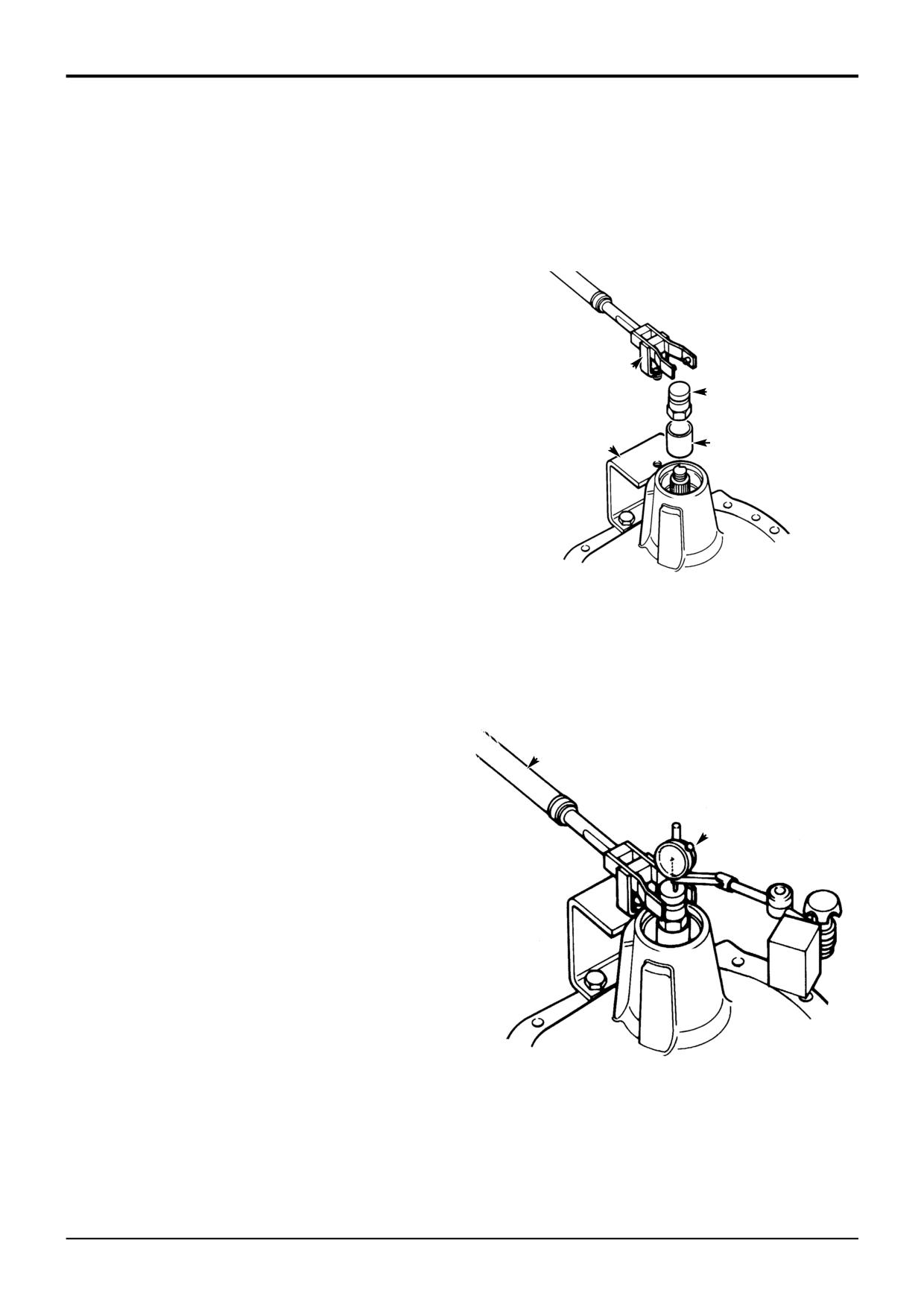
6
Fit special bracket D to the drive-head housing using
aspects of the drivehead assembly, which are covered
two M10 x 30 nuts and bolts. Fit special tool support
separately in detail as sub topics later in this section:
pillar E to bracket D so that the fork end engages in
adapter C. Ensure that fork E is centrally located on
Pinion Depth Setting
adapter C. If necessary, re-align bracket D to suit.
Collapsible Spacer Assembly
Crown Wheel and Pinion Meshing
Note: Both the crownwheel 15 and pinion 20 and the bevel
gears 9 and 10 are matched and should be renewed as sets
if any of their components are damaged or excessively
worn. The two differential housing halves 8A and 8B are also
matched. Do not use unmatched halves.
E
Make sure all bearings are lightly oiled before fitting and
C
setting. Make sure bearings are rotated whilst being set.
1
Determine the correct thickness required for the shims
23, refer to Pinion Depth Setting.
D
B
2
Fit shims 23 behind new bearing cup 22.
3
Fit new pinion head bearing cone 22 onto pinion 20.
4
Install pinion and bearings into the drive head casing.
348030
Install largest available solid spacer 24 e.g (14.20 mm)
and fit pinion tail bearing 21 (lightly oiled). Do not fit the
oil seal 19 at this stage.
7
Fit dial test indicator (DTI) F. Ensure that the DTI is
mounted on the drive head and not on bracket D.
Note: It should be noted that the axle is assembled using a
solid spacer. However, in the absence of the special tools
required or the correct size solid spacer 24 it is acceptable
8
Set torque wrench G to 35 Nm (25.8 lbf ft) and measure
to fit a collapsible spacer, refer to Collapsible Spacer
the end float while rotating the shaft.
Assembly.
5
Fit special tool sleeve B and special pinion shaft
G
adapter C. Tighten adapter C to approximately 50 Nm,
making sure the pinion is free to rotate and there is end
float, this will prevent any damage to the bearing. If the
pinion is not free to rotate or there is no end float at this
stage check the bearing is fitted correctly. Also check
F
the correct size spacer has been fitted.
348040
9803/3280
Issue 1