JCB 3CX, 4CX, 214e, 214, 215, 217 & VARIANTS Backhoe Loader. Service Manual - page 24
Section F
Transmission
Section F
32 - 9
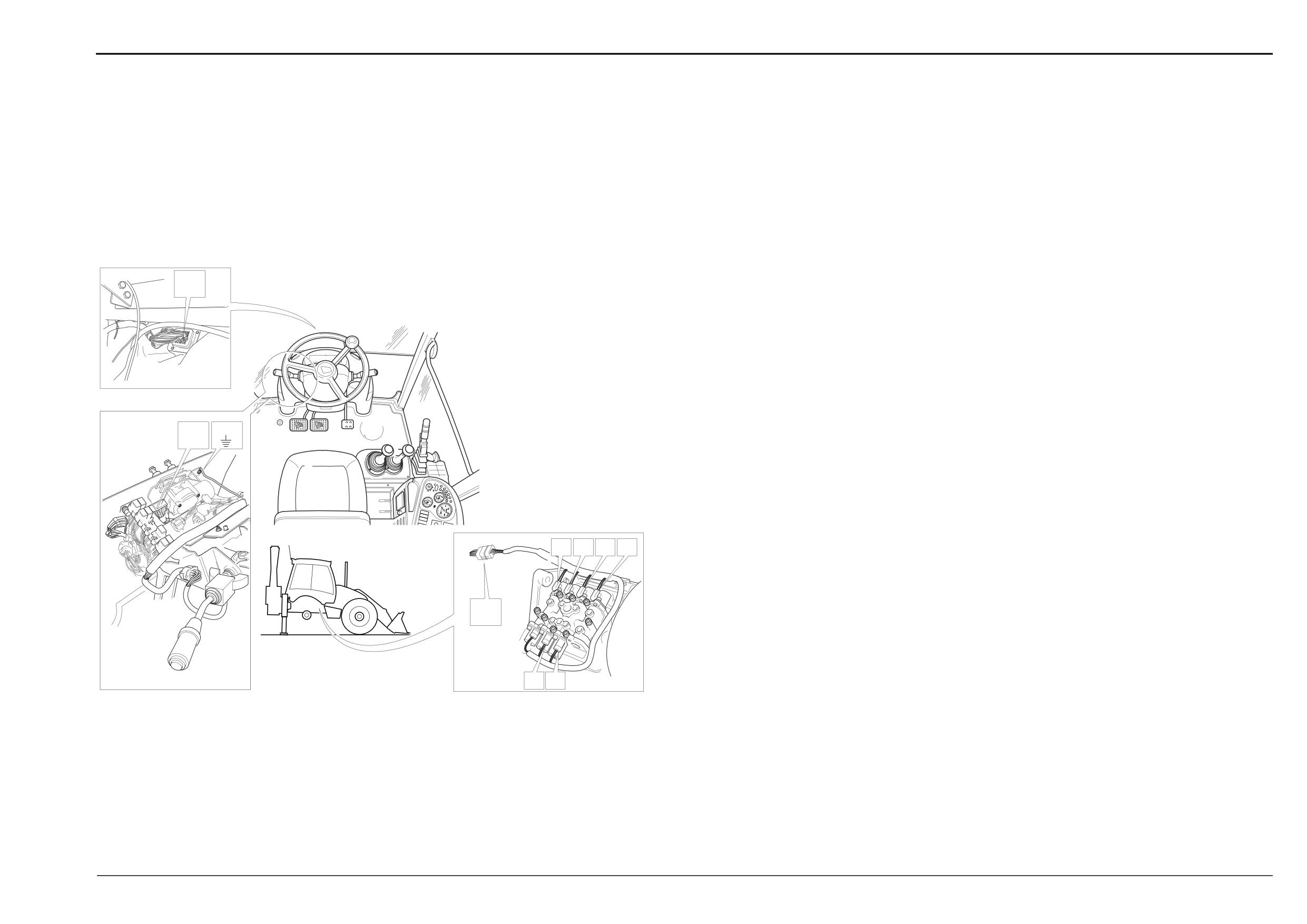
Electrical Connections
32 - 9
Powershift Gearbox - 4 Speed (cont’d)
(Machines up to 933756)
Electrical Connections - Wires and Connectors
Gearbox Solenoid Actuation
For relay activation see previous page.
Component Key (solenoid activation):
The following key identifies the component connectors on
the diagrams opposite. Note that the wires coloured green
show the electrical ‘feed to earth’ for the gearbox mounted
solenoids. Live feed (wires coloured red) to the relay
switches is supplied via the dump relay FG. Note that the
LA
destination for wire 107 from splice SS is shown on the relay
actuation diagram (previous page).
h1
Harness - 721/10940 Front console
h2
Harness - 721/10942 Link
h5
Harness - 721/10939 Gearbox
Note: For harness drawings see Section C.
Connectors (h1)
FA
h1 Î h2
FB1
Earth point
FD1
Forward high/low relay
FA
FB1
FD2
Forward relay
FE1
Reverse high/low relay
FE2
Reverse relay
FF1
Interlock relay
FF2
Mainshaft/layshaft relay
FG
Transmission dump relay
X
For wire 107 destination see Relay Actuation diagram
Connectors (h2)
LA h1 Î h2
F
E
I
J
LC h2 Î h5
Connectors (h5)
C10
h5 - h2
C20
Gearbox solenoid U (labelled E)
LC
C30
Gearbox solenoid T (labelled F)
C10
C40
Gearbox solenoid Y (labelled G)
C50
Gearbox solenoid Z (labelled H)
C60
Gearbox solenoid W (labelled I)
C70
Gearbox solenoid V (labelled J)
G
H
Splices (h1)
A404900
SS
ST
Splices (h2)
SC
Splices (h5)
SA
Earth Points
Faults may be caused by poor earth connections. Although
earth connections are shown opposite, it must be
remembered that the cab assembly is earthed via further
earth strap and cable connections. For details of these
connections see Section C, Machine Earth Connections.
9808/3270
Issue 1
Section F
Transmission
Section F
33 - 1
Electrical Connections
33 - 1
Powershift Gearbox - 6 Speed
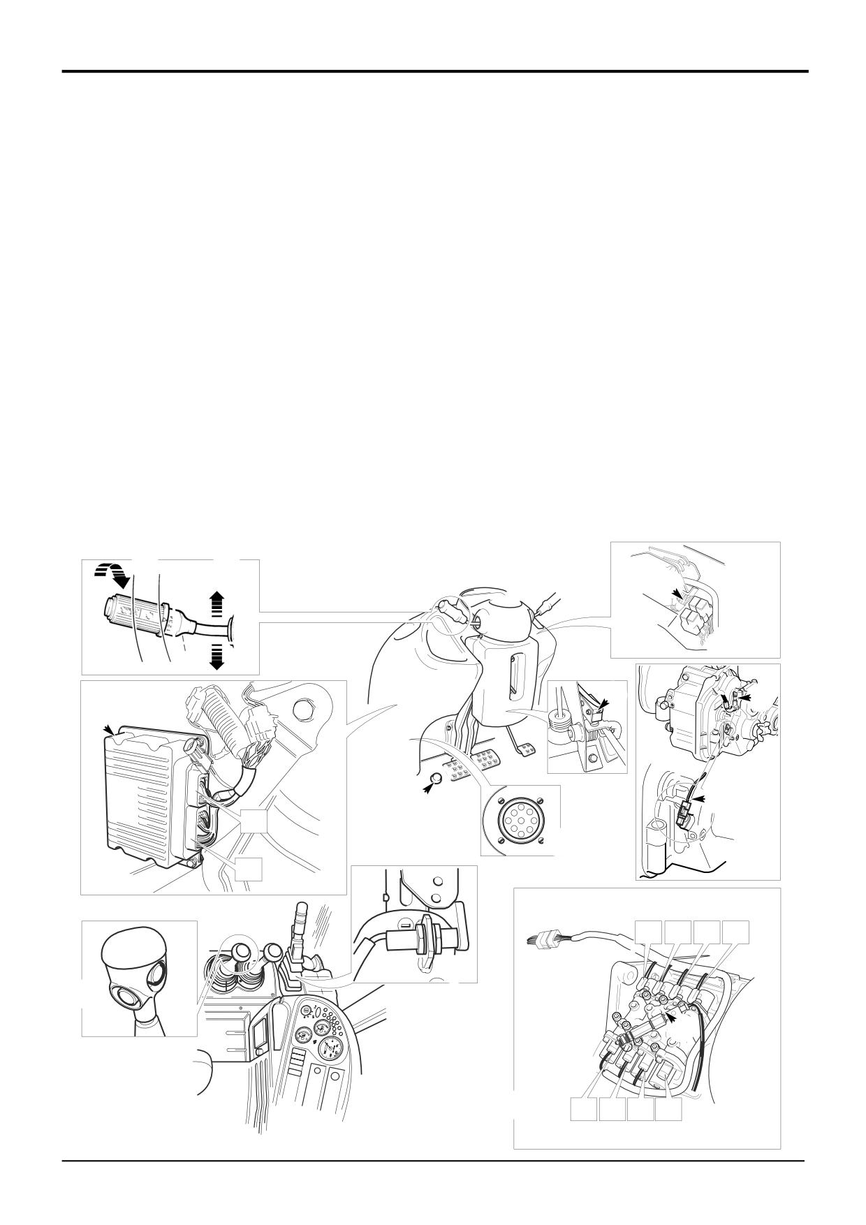
Introduction
This section explains how the Powershift 6 speed
The ECU can be connected to diagnostics software loaded
(ShiftMaster) electrical system works .
on a laptop PC. The commincations link is facilitated via
diagnostics socket 3. See Powershift Gearbox - 6 Speed,
Central to the system is the ShiftMaster ECU (Electronic
ShiftMaster Diagnostics - User Guide.
Control Unit) 1. The unit receives ‘inputs’ from electrical
Note: The ECU also controls 2/4WD selection by activating
devices such as the gear select switch B. Depending on the
relay S. 2/4WD electrical system is not described in this
input signals the ECU ‘outputs’ energise electrical devices
section.
such as gearbox solenoid control valves 2.
Component Identification
ECU input devices
ECU output - activated devices
B
Gear select switch
N
In-cab warning light - high gearbox oil temperature
C
Forward/Neutral/Reverse select switch
P
In-cab warning light - low gearbox oil pressure
D
Transmission dump switch
R
In-cab master warning light and buzzer
E
Gearbox oil temperature switch
S-Z
Gearbox solenoid control valves
F
Park brake switch
G
Transmission dump relay
Note: For identification of in-cab warning lights see the
H
Speed sensor - gearbox mounted
machine Operator Handbook.
J
Kick down switch
K
Throttle switch
L
Gearbox oil pressure switch
B
C
1
G
2
F
3
N
A
R
E
K
1
J
D
H
C
E
B
A
F
GC
J
G
H
3
GB
T
U
W
V
F
D
L
2
S
Y
Z
X
A405360
9803/3280
Issue 2*
Section F
Transmission
Section F
33 - 2
Electrical Connections
33 - 2
Powershift Gearbox - 6 Speed
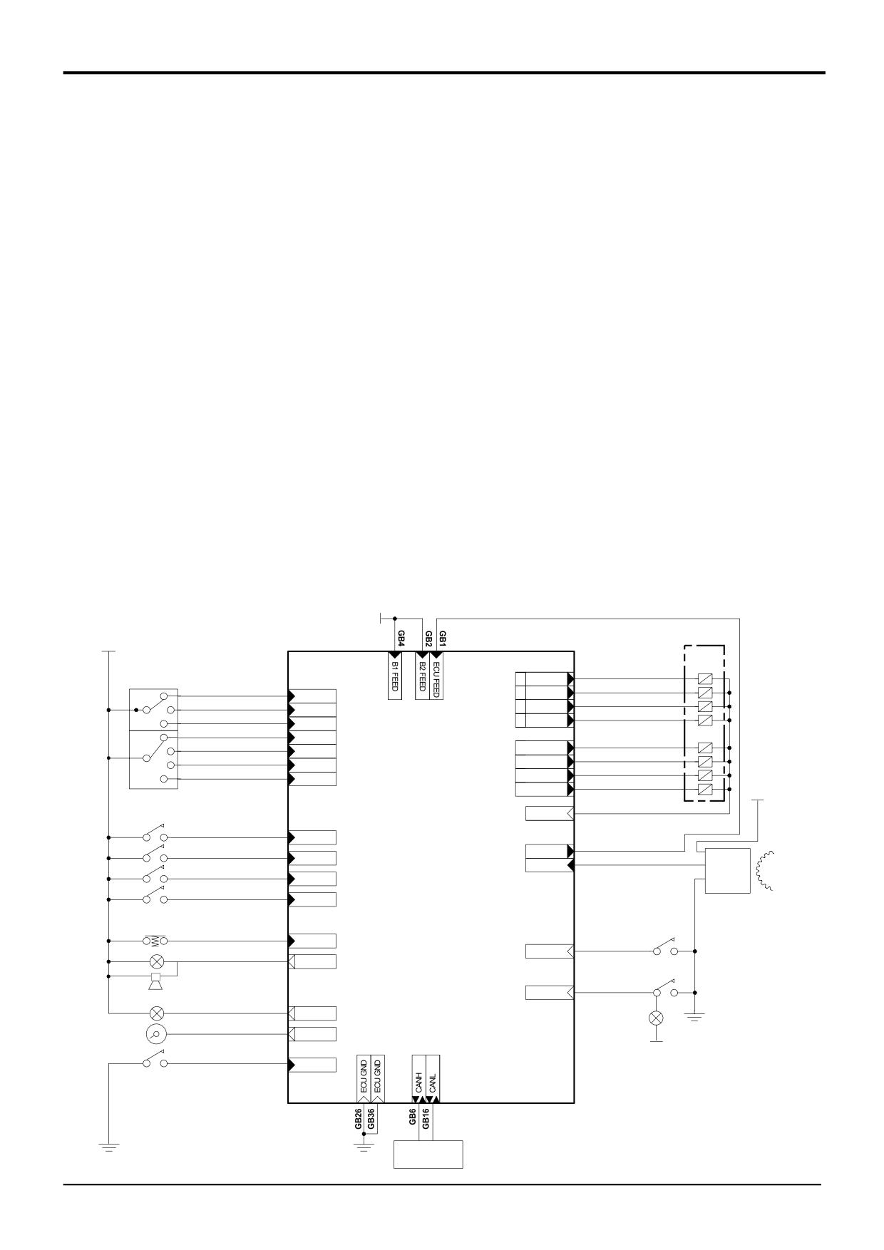
ECU Electrical Connections
GB1
Feed from GC10
GC3
Speed sensor -
GB2
12v Feed
input
Electrical connections at the ECU are shown in the diagram
GB4
12v Feed
GC4
Output - ‘Z’ solenoid
below. Connections are divided into two groups;
GB6
Diagnostics connector
GC6
Output - ‘U’ solenoid
GB Connections to components mounted on the gearbox
GB7
Forward switch
GC10 Feed to GB1
GC Connections to components mounted elsewhere on the
GB8
2nd gear switch
GC11 Switch
machine.
GB13 Warning lamp
Low trans oil pressure
For the key to the main components see Component
Low trans oil pressure
GC12 Output - ‘X’ solenoid
Identification on the previous page. For more detailed
GB14 Speedometer input
GC13 ECU Earth
explanations of the electrical connections for gearbox
GB17 Auto gear switch
GC15 Output - ‘Y’ solenoid
control see subsequent pages.
GB18 1st gear switch
GC18 Output - ‘S’ 4WD
GB19 Throttle switch
solenoid
Note: When fault finding DO NOT use a multimeter on the
GB20 Foot brake switch
GC20 Output - ‘V’ solenoid
ECU connector pins. Only test the associated wiring,
(4WD/4 wheel brake)
GC21 Switch
uncouple connectors GB and GC and then use a multimeter
GB24 Diagnostics connector
Trans oil temperature
at the pins inside these connectors as applicable. Use the
GB25 Master warning lamp
GC23 Output - ‘W’ solenoid
ShiftMaster Diagnostics system to identify possible faults
GB26 ECU Earth
GC24 Output - ‘T’ solenoid
with the ECU See Powershift Gearbox
- 6
Speed,
GB27 3rd gear switch
ShiftMaster Diagnostics - User Guide.
GB28 Neutral switch
GB30 Parkbrake ON switch
GB36 ECU Earth
GB37 Trans dump switch
GB38 Reverse switch
GB39 Kickdown switch
GB40 4WD switch
(IGNITION)
12V
12V
S-Z
C
GC4
'Z' SOLENOID
OUT
FORWARD
GB7
GC6
'U' SOLENOID
F
IN
OUT
NEUTRAL
GB28
GC12
'X' SOLENOID
N
OUT
IN
GC15
'Y' SOLENOID
R
REVERSE
GB38
OUT
IN
1
GEAR 1
GB18
IN
GEAR 2
GB8
GC18
4WD SOLENOID 'S'
2
IN
OUT
GC20
'V' SOLENOID
3
GEAR 3
GB27
OUT
IN
GC23
'W' SOLENOID
A
GEAR A
GB17
OUT
IN
GC24
'T' SOLENOID
OUT
12V
B
GC13
BANK 1 GROUND RETURN
GND RTN
K
THROTTLE
GB19
IN
GC10
D-4WD
GB20
IN
GC3
TRANS SPEED
FREQ2
SPEED
D
DUMP
GB37
IN
1
SENSOR
I-4WD
GB40
IN
ShiftMaster ECU
H
J
L
KICKDOWN
GB39
LOW TRANS
IN
GC11
OIL PRESS
IN
GB25
DRIVER INDICATOR
OUT
R
E
HI TRANS
GC21
OIL TEMP
IN
P
LOW OIL PRESSURE
GB13
OUT
N
SPEEDOMETER
GB14
OUT
12V
F
PARK
BRAKE
GB30
IN
A408760
DIAGNOSTICS
CONNECTOR
3
9803/3280
Issue 1
Section F
Transmission
Section F
33 - 3
Electrical Connections
33 - 3
Powershift Gearbox - 6 Speed
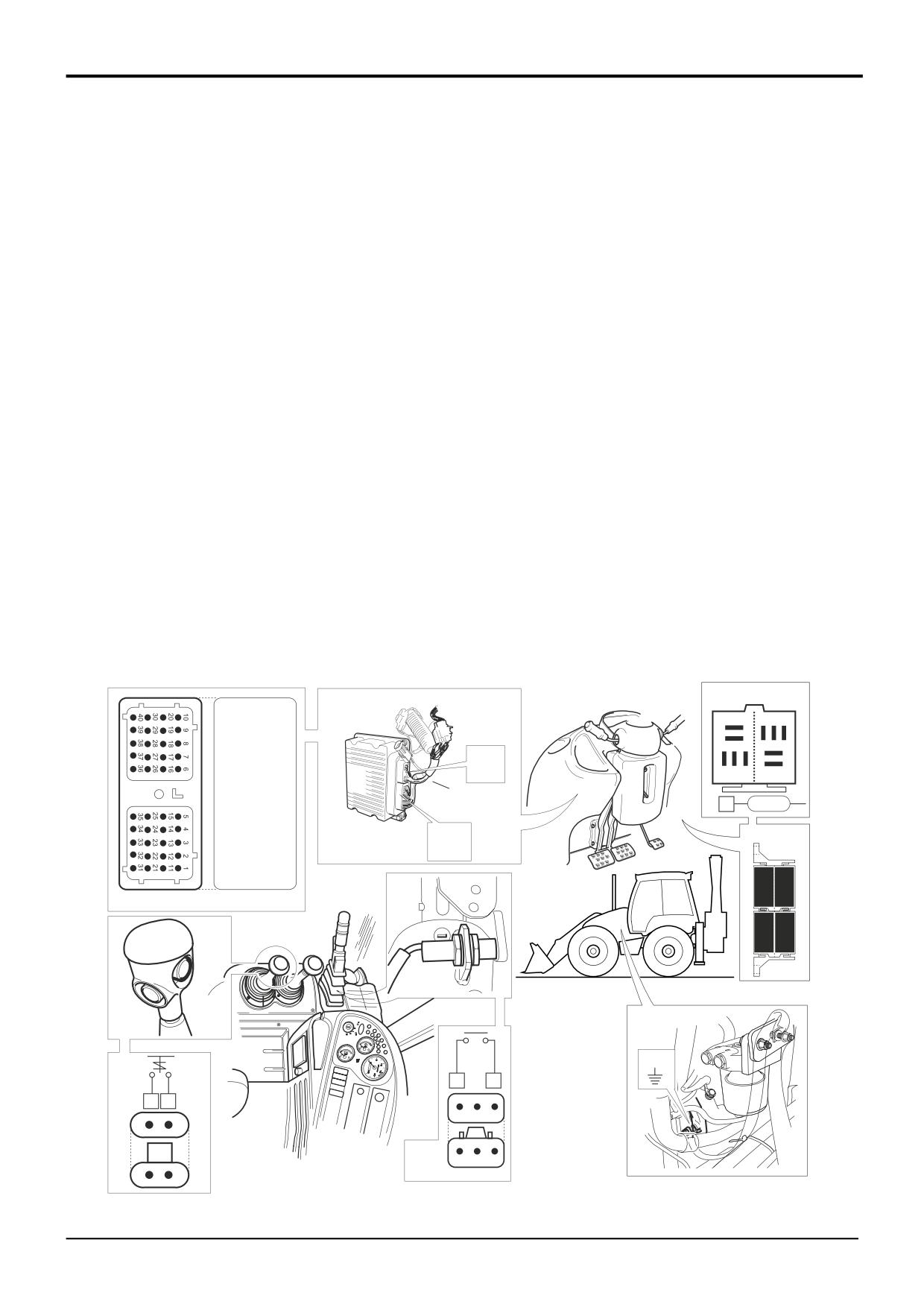
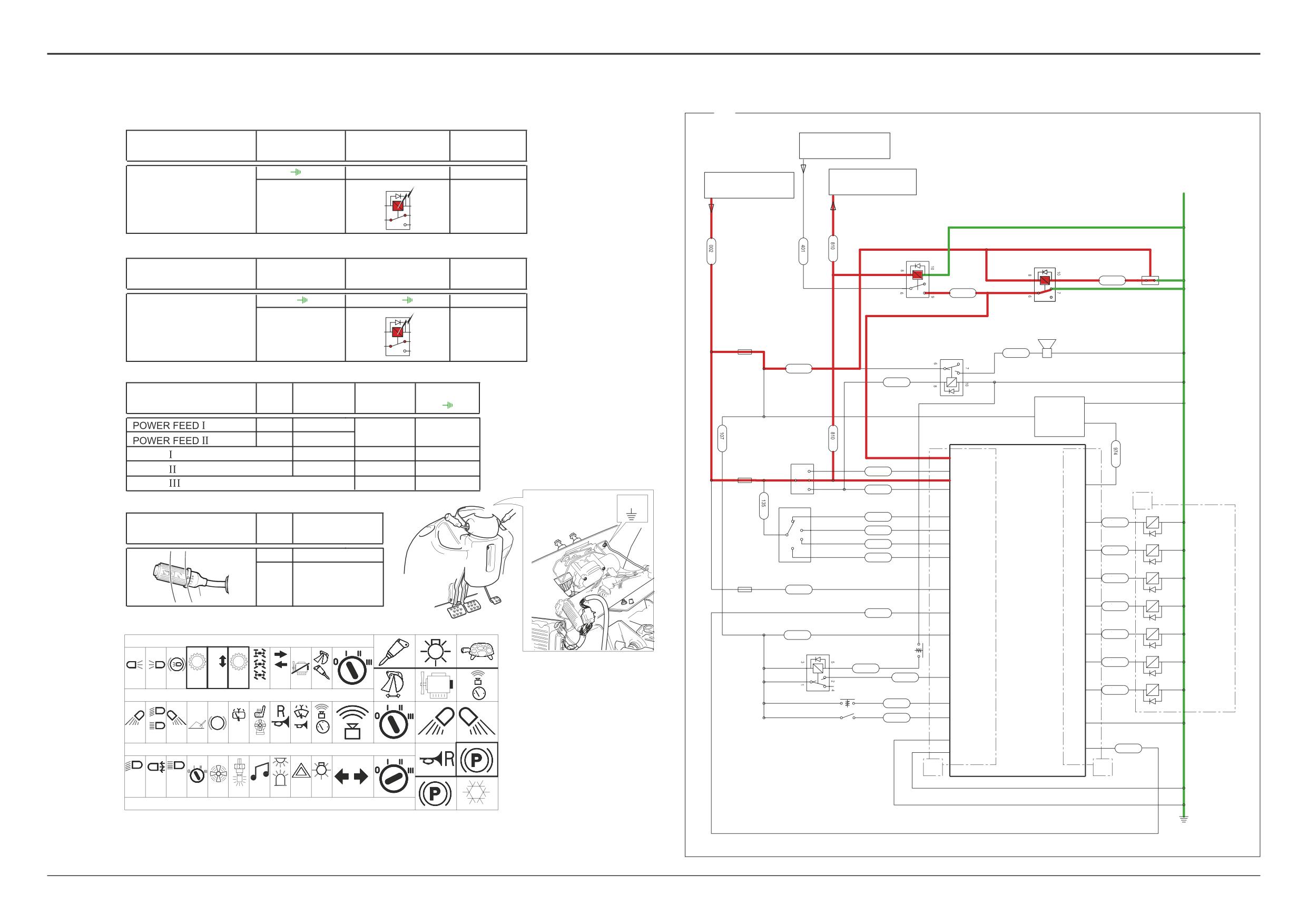
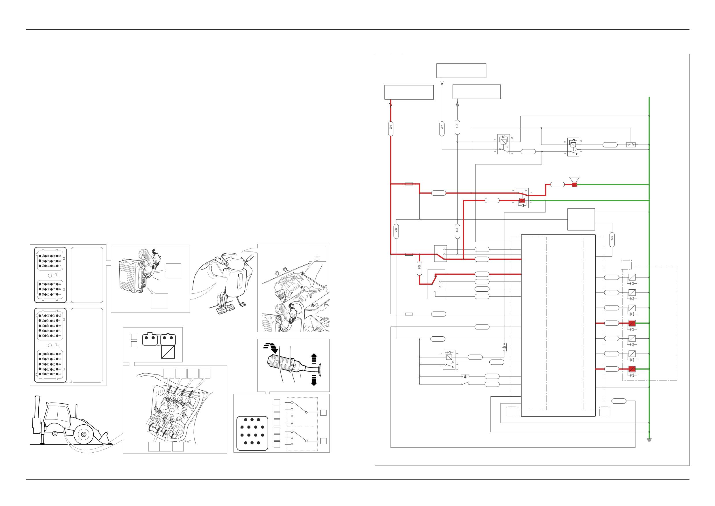
Electrical Connections - Quick Reference
Diagram X
The tables show live connector pins and also relevant earth
The diagram X (opposite) shows the electrical circuit for the
destinations for given gearbox functions/systems as follows:
gearbox control. It is shown with neutral selected and the
E.C.U. feeds and earths
park brake ON. ‘Live feed’ wires are coloured red and feed
Transmission Dump
to earth are green.
Park Brake ON (Transmission Dump)
1, 2, 3, 4(A), 5(A), 6(A) Forward (see following pages)
Key
Neutral (see following pages)
A
Gearbox solenoids
1, 2, 3, 4 Reverse (See following pages)
C50
Reverse alarm
CM
Park brake warning light relay
The information is intended as an aid when checking for
DW
Park brake switch
faulty wires or connectors by means of continuity tests using
DZ
Park brake relay
a multimeter. DO NOT use a multimeter on the ECU
FL
Column switch
connector pins (connectors A and B). Only test the
FG1
Transmission dump relay
associated wiring, uncouple connectors GB and GC and
FG2
Reverse alarm relay
then use a multimeter at the pins inside these connectors as
GB
Harness connector - ECU ‘A’
applicable. Use the ShiftMaster Diagnostics system to
GC
Harness connector - ECU ‘B’
identify possible faults with the ECU See Powershift
GG
Throttle switch
Gearbox - 6 Speed, ShiftMaster Diagnostics - User
LE
Kick down switch
Guide.
NG
Transmission dump switch
Note that interconnecting harness connectors are not shown
here. For full details see the relevant expanded harness
schematic in this section.
Note: Identify dump relay FG1 by locating wire 1873 at pin 2
of the corresponding relay base.
FG1
5
4
3
6
7
2
GC
1
B
8 9 10
E.C.U. A
A
2
1873
GB
GB
MB1
NG
3
2
A
B
3
2
1
A
B
DW
3
2
1
A
B
A408740
9803/3280
Issue 1
Section F
Transmission
Section F
33 - 4
Electrical Connections
33 - 4
Powershift Gearbox - 6 Speed
X
Gearbox
Dump Switch NG
Relay FG1
E.C.U. GB
FROM PARKBRAKE
function
WARNING LIGHT
A - B
(MB1)
3 - 5, 1 - 2
37
TRANSMISSION DUMP
TO NEUTRAL
FROM IGNITION
START RELAY
RELAY 1
5
3
2
1
PARKBRAKE RELAY
DW
Gearbox
Park Brake Switch
Relay DZ
3
DW
E.C.U. GB
1
2
function
936
P/BRAKE SWITCH
815
1, 3, 2
(DR2)
8 - 10, 6 - 7 (DR2)
30
PARK BRAKE ON
CM
DZ
(TRANSMISSION DUMP)
10
8
C50
7
REV ALARM
6
9
10
FG2
847
REVERSE ALARM
FUSE A5
107
REVERSE ALARM
808
RELAY
E.C.U.
C17
Fuse
E.C.U. GB
E.C.U. GC
Earth Point
1
Power supply & Earths
SPEED SENSOR
3
SPEED
2
SENSOR
A5
4
A7
2
EARTH
26
FB1
FOR / REV
30
SWITCH
FL
PARKBRAKE
36
F
4
7
EARTH
FB1
809
FORWARD
11
12
7
N
6
28
3
NEUTRAL
EARTH
13
FB1
R
10
38
FUSE A6
808
REVERSE
A
FB1
1
12
18
883
24
1
2
Column Switch FL
1st GEAR
Switch Connector
9
8
1860
'T' SOLENOID
Fuse
14
2
F
Power supply
856
2nd GEAR
FL
3
5
27
857
3rd GEAR
6
1
2
17
1861
'U' SOLENOID
A6
7, 14
A
13
E
858
AUTOMATIC
GEAR
FL
SELECTOR
20
1
2
1862
'V' SOLENOID
13
16
2
J
BANK 2 +VE
136
FUSE A7
23
1
2
1
ECU
1863
'W' SOLENOID
1876
ECU + FEED
I
4
12
1
2
107
BANK 1 +VE
1864
'X' SOLENOID
817/18221
A7 A6 A5
B
H
FG1
NG
F
A
15
1
2
II
I
1865
'Y' SOLENOID
934
37
G
R
1873
DUMP RELAY
5A
5A
7.5A
10A
3A
10A
7.5A
7.5A
5A
10A
4
1
2
LE
1866
'Z' SOLENOID
39
6
992
KICKDOWN
1
2
19
991
THROTTLE
13
1
2
-VE
GG
SWITCH
25A
20A
25A
5A
10A
10A
15A
7.5A
15A
5A
26
10
36
1876
DZ
GB
GC
-VE
15A
3A
15A
3A
30A
20A
5A
10A
15A
7.5A
A408730
-VE
A409280
9808/3280
Issue 1
Section F
Transmission
Section F
33 - 5
Electrical Connections
33 - 5
Powershift Gearbox - 6 Speed
X
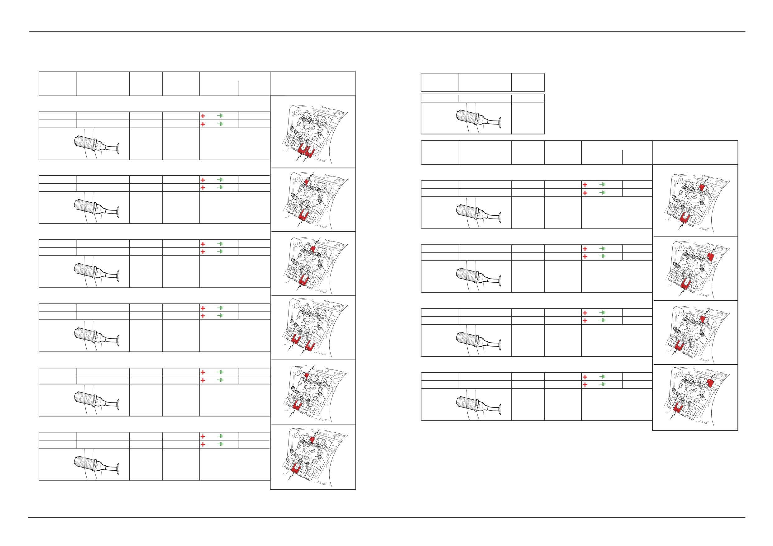
Electrical Connections - Quick Reference
Diagram X
FROM PARKBRAKE
WARNING LIGHT
The tables show live connector pins and also relevant earth
The diagram X (opposite) shows the electrical circuit for the
destinations for given gearbox functions/systems as follows:
gearbox control. It is shown with 1st gear reverse selected.
TO NEUTRAL
ECU feeds and earths (see previous pages)
‘Live feed’ wires are coloured red and feed to earth are
FROM IGNITION
RELAY 1
START RELAY
Transmission Dump (see previous pages)
green.
Park Brake ON (Transmission Dump) (see previous
pages)
Key
1, 2, 3, 4(A), 5(A), 6(A) Forward
A
Gearbox solenoids
Neutral
C50
Reverse alarm
1, 2, 3, 4 Reverse
CM
Park brake warning light relay
DW
Park brake switch
PARKBRAKE RELAY
DW
3
The information is intended as an aid when checking for
DZ
Park brake relay
1
2
936
P/BRAKE SWITCH
faulty wires or connectors by means of continuity tests using
FL
Column switch
815
a multimeter. DO NOT use a multimeter on the ECU
FG1
Transmission dump relay
CM
DZ
connector pins (connectors A and B). Only test the
FG2
Reverse alarm relay
associated wiring, uncouple connectors GB and GC and
GB
Harness connector - ECU ‘A’
C50
then use a multimeter at the pins inside these connectors as
GC
Harness connector - ECU ‘B’
REV ALARM
applicable. Use the ShiftMaster Diagnostics system to
GG
Throttle switch
9
10
FG2
847
REVERSE ALARM
identify possible faults with the ECU See Powershift
LE
Kick down switch
FUSE A5
Gearbox - 6 Speed, ShiftMaster Diagnostics - User
NG
Transmission dump switch
107
Guide.
808
REVERSE ALARM
C17
RELAY
1
SPEED SENSOR
Remember that any interconnecting harness connectors are
3 SPEED
not shown here. For full details see the relevant expanded
2
SENSOR
harness schematic in this section.
FOR / REV
30
SWITCH
FL
PARKBRAKE
F
4
7
809
FORWARD
FB1
11
12
7
N
6
28
NEUTRAL
3
R
10
38
FUSE A6
808
REVERSE
A
GC
1
12
18
B
883
1st GEAR
24
1
2
E.C.U. B
1860
'T' SOLENOID
2
9
8
14
856
F
A
2nd GEAR
3
5
27
857
3rd GEAR
6
1
2
17
1861
'U' SOLENOID
A
13
858
AUTOMATIC
E
GB
GEAR
FL
SELECTOR
20
1
2
1862
'V' SOLENOID
13
16
2
J
136
BANK 2 +VE
FUSE A7
23
1
2
1
ECU
1863
'W' SOLENOID
1856
ECU + FEED
I
1
4
12
1
2
107
BANK 1 +VE
1864
'X' SOLENOID
1
2
2
1
B
6
2
E.C.U. A
FG1
NG
A
15
1
2
1
1865
'Y' SOLENOID
934
37
G
2
F
1873
DUMP RELAY
4
1
2
3
N
LE
1866
'Z' SOLENOID
39
H
F
E
I
J
A
R
992
KICKDOWN
1
2
19
991
THROTTLE
13
1
2
-VE
GG
SWITCH
26
10
FL
12
1
36
1876
9
2
14
GB
GC
5
3
1
2
3
13
A
-VE
4
5
6
7
4
F
-VE
8
9
10
11
6
N
7
10
R
G
H
6
12
13 14
A408710
A409290
9808/3280
Issue 1
Section F
Transmission
Section F
33 - 6
Electrical Connections
33 - 6
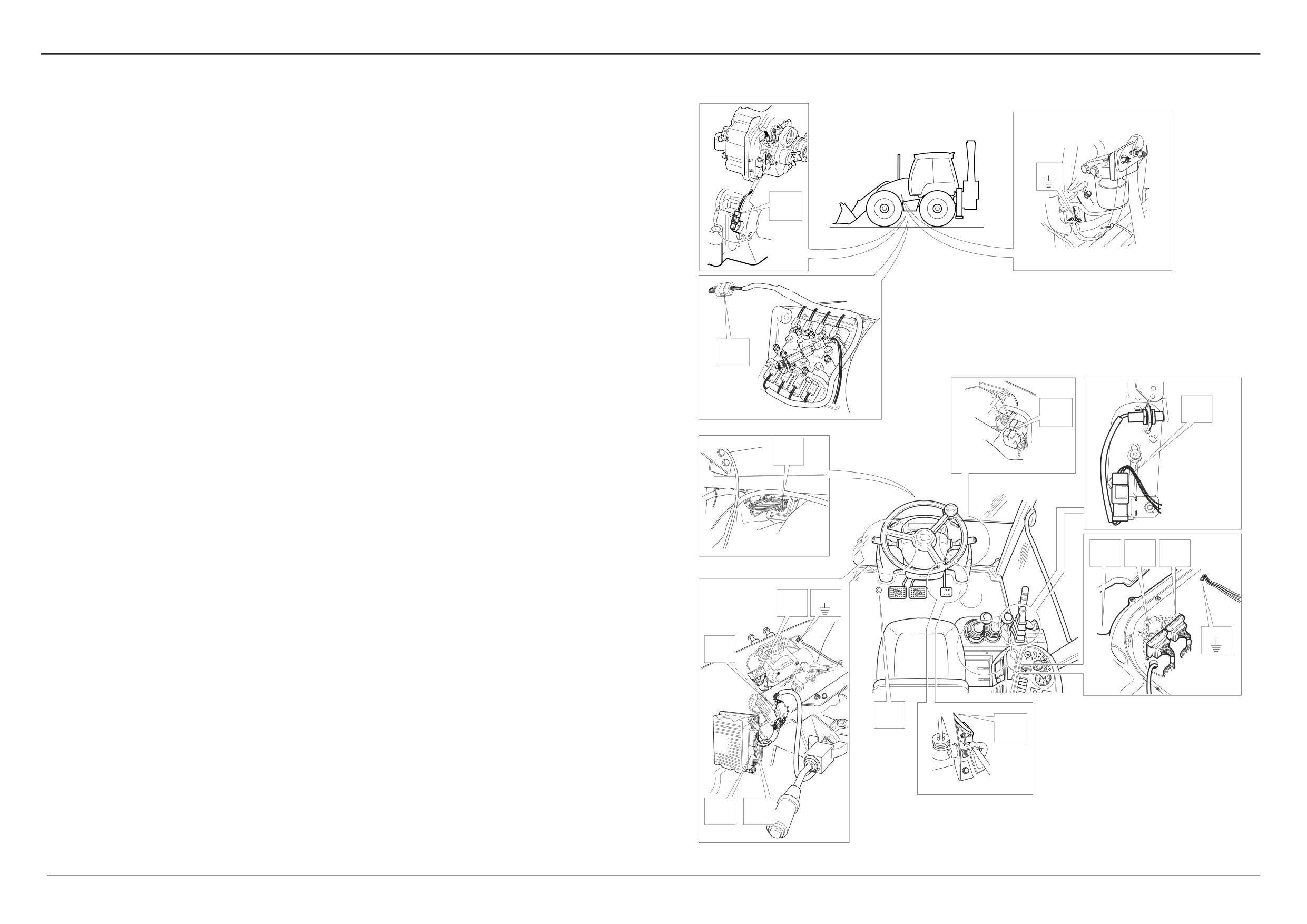
Gearbox
Column Switch FL
E.C.U. GB
E.C.U. GC
Solenoid Connector
Gearbox Solenoid
Gearbox
Column Switch FL
E.C.U. GB
function
(Inputs)
(Outputs)
function
Labelled
NEUTRAL
7 - 6
28
1st GEAR
14 - 12
18
4 (Z)
1, 2
(FB1)
H
N
FORWARD
7 - 4
7
12 (X)
1, 2
(FB1)
6
1F
Gearbox
Column Switch FL
E.C.U. GB
E.C.U. GC
Solenoid Connector
Gearbox Solenoid
X ,Z
function
(Inputs)
(Outputs)
Labelled
Z
X
T
W
2nd GEAR
14 - 9
8
4 (Z)
1, 2
(FB1)
H
1st GEAR
14 - 12
18
4 (Z)
1, 2
(FB1)
H
FORWARD
7 - 4
7
24 (T)
1, 2
(FB1)
F
REVERSE
7 - 10
38
23 (W)
1, 2
(FB1)
I
2F
1R
T ,Z
W ,Z
Z
Z
U
3rd GEAR
14 - 5
27
4 (Z)
1, 2
(FB1)
H
V
2nd GEAR
14 - 9
8
4 (Z)
1, 2
(FB1)
H
FORWARD
7 - 4
7
6 (U)
1, 2
(FB1)
E
REVERSE
7 - 10
38
20 (V)
1, 2
(FB1)
J
3F
2R
U ,Z
V ,Z
Z
Z
W
4th GEAR (A)
14 - 13
17
15 (Y)
1, 2
(FB1)
G
3rd GEAR
14 - 5
27
15 (Y)
1, 2
(FB1)
G
FORWARD
7 - 4
7
12 (X)
1, 2
(FB1)
6
REVERSE
7 - 10
38
23 (W)
1, 2
(FB1)
I
A
3R
X ,Y
Y
W ,Y
X
Y
T
V
5th GEAR (A)
14 - 13
17
15 (Y)
1, 2
(FB1)
G
4th GEAR
14 - 13
17
15 (Y)
1, 2
(FB1)
G
FORWARD
7 - 4
7
24 (T)
1, 2
(FB1)
F
REVERSE
7 - 10
38
20 (V)
1, 2
(FB1)
J
A
4R (A)
T ,Y
V ,Y
Y
Y
U
A408720
6th GEAR (A)
14 - 13
17
15 (Y)
1, 2
(FB1)
G
FORWARD
7 - 4
7
6 (U)
1, 2
(FB1)
E
A
U ,Y
Y
A408700
9808/3280
Issue 1
Section F
Transmission
Section F
33 - 7
Electrical Connections
33 - 7
Powershift Gearbox - 6 Speed
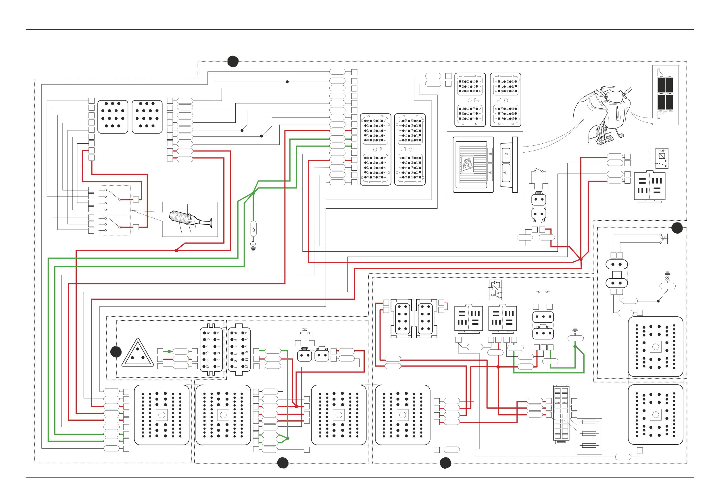
Connectors (h3)
CA
h3 Î h4
Electrical Connections - Wires and Connectors
Schematics are divided into 2 parts: Input Controls and
CB
h3 Î h2
MB1
Gearbox Solenoid Actuation.
CM
Park brake warning light relay
CCA Fuses
On the electrical diagram opposite the electrical connectors
DR2 Earth point
C17
(example, FA to LA) are shown looking on the mating face of
DZ
Park brake relay
each connector when they are disconnected.
DW
Park brake switch
EA
Immobiliser
The wire numbers and colours, where appropriate, are
EAB Link - immobiliser (if immobiliser is not fitted)
shown as an aid to identification whilst fault finding.
Connectors (h4)
Before fault finding make sure that you understand how the
NH h4 Î h3
the electrical circuits work. The most effective method of
NG Transmission dump switch
fault finding is by means of ShiftMaster Daignostics software
MB1 Earth point
and a laptop PC, see Service Procedures, Powershift
Gearbox - 6 speed, ShiftMaster Diagnostis - User Guide.
Splices (h1)
Having identified a faulty system, use the schematics to
SA
C10
identify the relevant wires and connectors, continuity checks
SC
LC
can then be carried out using a multimeter. Gearbox
SF
solenoid coils can be checked for the correct resistance
SJ
value as given in Technical Data. See Service Procedures,
SL
Electrical Testing Methods for more details.
SS
DW
FG
Input Controls
Splices h2
LA
SB
For gearbox solenoid actuation see subsequent pages.
SC
Component Key (Input controls):
Splices h3
The following key identifies the component connectors on
DW
the opposite diagrams. Note that the wires coloured red
TF
show the electrical ‘live feed’ to the column gear lever and
gearbox E.C.U..
Splices h4
SA
NG
LB
NH
h1
Harness - 721/10937 Front console
CB
CA
h2
Harness - 721/10971 Link
Splices h5
h3
Harness - 721/10970 Side console
SA
h4
Harness - 721/10935 Engine/mainframe
FA
FB1
h5
Harness - 721/10941 Transmission
Earth Points
Note: For harness drawings see Section C.
Faults may be caused by poor earth connections. Although
DR2
earth connections are shown opposite, it must be
FL
Connectors (h1)
remembered that the cab assembly is earthed via further
FA
h1 Î h2
earth strap and cable connections. For details of these
FB1
Earth point
connections see Section C, Machine Earth Connections.
FG
Transmission dump relay
Note: Identify dump relay FG by locating wire 1873 at pin 2
LE
A408640
of the corresponding relay base.
GG
FL
Column gear lever
GB
E.C.U. connector A
GC
E.C.U. connector B
GG
Throttle switch
Connectors (h2)
LA
h2 Î h1
LB
h2 Î h3
GB
GC
LC
h2 Î h5
LE
Kick down switch
9808/3280
Issue 1
Section F
Transmission
Section F
33 - 8
Electrical Connections
33 - 8
Powershift Gearbox - 6 Speed
Input Controls
h1
GC
B
815C
30
SJ
1876
10
808G
38
974
3
856
8
FL
809
7
9
9
856
883
18
4
1
2
3
3
2
1
4
809
GB
810D
28
A
10
4
5
6
7
7
6
5
4
10
808
858A
17
F G
1
12
8
9
10
11
11
10
9
8
12
883
857
27
6
12
13 14
14
13 12
6
810
SF
136
2
13
13
858
SL
600MJ
26
5
5
857
FG
600MK
36
14
7
135B
1873
37
107AL
3
5
3
7
14
135C
107X
4
2
GG
934B
5
1
4
992
39
991
19
1873
2
5 4
3
6
107AD
1
1876
1
7
2
1
2
12
1
SA
1
9
2
8 9 10
14
5
3
2
1
13
A
2
1
4
F
6
N
7
10
R
2
1
h4
991
107T
2 c
SC
FB1
A
B
A
B
SS
NG
MB1
A
B
DW
10
8
600A
7
A
B
EA
EAB
6
CM
9
DZ
6
6
600EZ
1
2
SA
3
4
5
5
4
3
5 4
3
5 4
3
6
6
934A
42
7
7
3
6
6
3
2
2
3
2
1
12
20
24
28
35
48
2
7
7
2
1
1
DR2
8 9 10
8 9 10
C17
C10
LC
1
8
8
1
3
2
1
9
6
8
10
7
619
LE
1
2
SA
815
600MM
3
1
2
SC
NH
1
600Z
1
1
600Z
1
107U
h5
1
107AN
3
107AK
6
6
107AK
2
1
1
2
2
992
135D
936
2
3
600BF
2
974
7
7
974
135
107AP
TF
1
13
21
25
29
37
CB
CCA
12
24
30
36
48
60
60
48
36
30
24
12
12
24
30
36
48
60
60
48
36
30
24
12
20
19
12
20
24
28
35
48
974
42
42
974
18
17
934
7
7
934
7
7
934F
136
14
16
15
13
107
34
34
107H
34
14
13
34
107H
135D
12
11
SB
12
11
135
52
52
135
52
107
10
9
52
135
10
9
CA
136
53
53
136
53
8
7
53
136
992
45
6
4
45
992
FUSE A7
4
3
600DP
49
49
600DP
2
1
600DN
50
1
13
25
31
39
49
49
39
31
25
13
1
50
1
13
25
31
39
49
49
39
31
25
13
1
FUSE A6
1
13
21
25
29
37
600DN
SC
815C
10
10
815A
10
10
815A
42
FA
LA
LB
CB
FUSE A5
934F
h2
h3
A404930
9803/3280
Issue 1
Section F
Transmission
Section F
33 - 9
Electrical Connections
33 - 9
Powershift Gearbox - 6 Speed
Gearbox Solenoid Actuation
h1
GC
B
1864
12
1861
6
1860
24
1862
20
1863
23
1866
4
1865
15
600MH
13
600Z
1865
1866
1863
1862
1860
1861
F
G
1864
1860
1
1865
1
1
11
10
9
3
8
4
12
1
2
2
1
1
2
2
1
600BX
2
600BZ
2
C30
T
C40
Y
12
11
10
9
5
6
C10
1
2
3
4
8
7
E
H
FB1
1861
1
1
2
3
4
5
6
1866
1
2
2
1
1
LC
600BS
2
1
2
2
1
600BY
2
621
12
11
10
9
8
7
C20
U
C50
Z
1
11
10
9
3
8
4
12
SA
I
600Z
6
SC
1863
1
FA
LA
1
2
2
1
1864
1
600CA
2
1
2
2
1
600ME
2
12
24
30
36
48
60
60
48
36
30
24
12
600DN
50
50
600DN
C60
W
C90
X
600DP
49
49
600DP
J
1865
19
19
1865
1862
1
1866
16
16
1866
1
2
2
1
600BT
2
1863
15
15
1863
C70
V
1862
13
13
1862
1
13
25
31
39
49
49
39
31
25
13
1
1860
11
11
1860
1861
6
6
1861
1864
51
51
1864
SA
h2
h5
A408630
9808/3280
Issue 1
Section F
Transmission
Section F
33 - 10
Electrical Connections
33 - 10
Powershift Gearbox - 6 Speed (cont’d)
Electrical Connections - Wires and Connectors
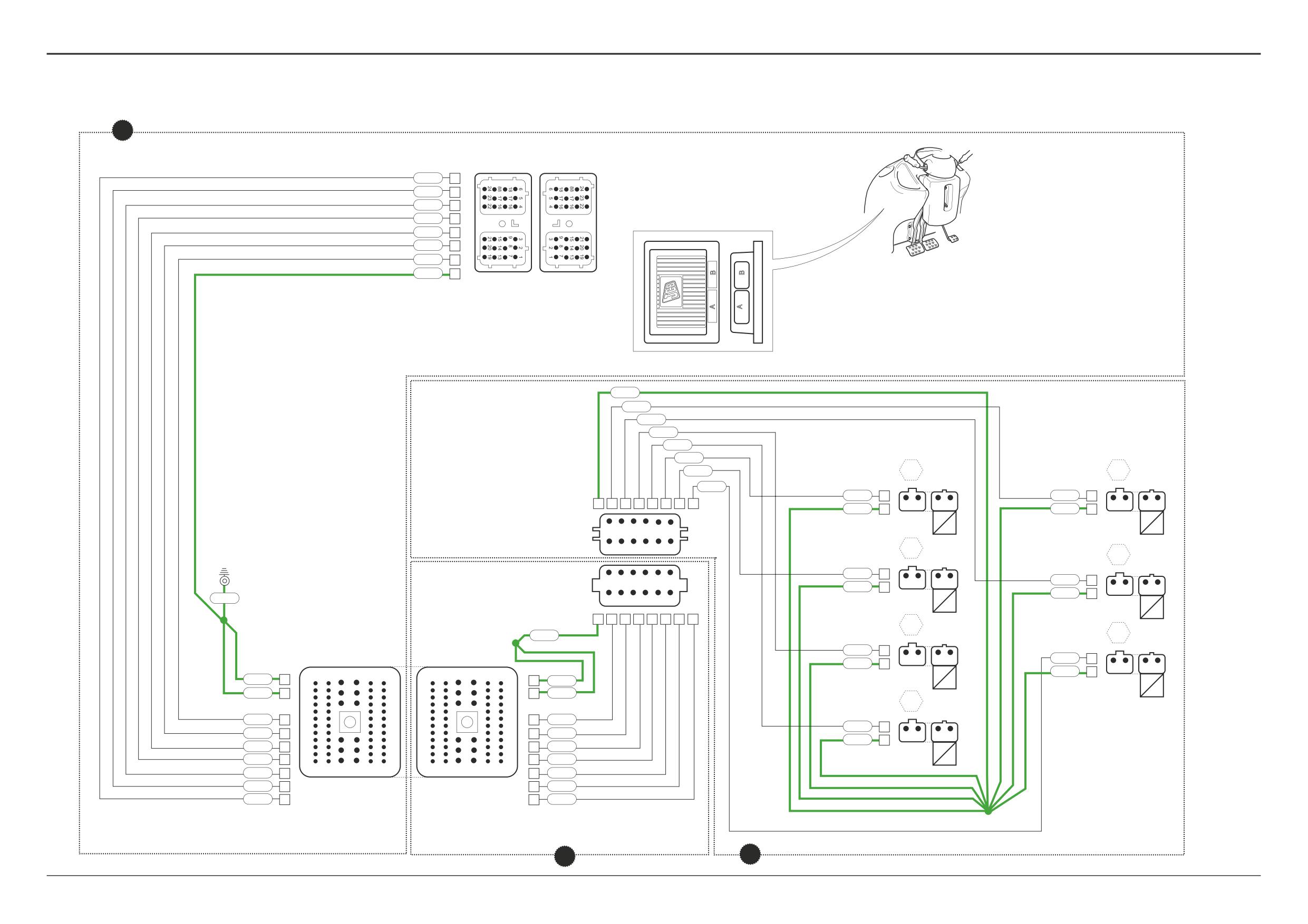
Gearbox Solenoid Actuation
For input controls see previous page.
Component Key (solenoid activation):
The following key identifies the component connectors on
the diagrams opposite. Note that the wires coloured green
show the electrical ‘feed to earth’ for the gearbox mounted
solenoids and gearbox ECU.
h1
Harness - 721/10937 Front console
LA
h2
Harness - 721/10971 Link
h5
Harness - 721/10941 Gearbox
Note: For harness drawings see Section C.
Connectors (h1)
GC E.C.U. connector B
FA
h1 Î h2
FB1
Earth point
Connectors (h2)
LA h1 Î h2
FA
FB1
LC h2 Î h5
Connectors (h5)
C10
h5 Î h2
C20
Gearbox solenoid U (labelled E)
C30
Gearbox solenoid T (labelled F)
C40
Gearbox solenoid Y (labelled G)
C50
Gearbox solenoid Z (labelled H)
C60
Gearbox solenoid W (labelled I)
C70
Gearbox solenoid V (labelled J)
F
E
I
J
C90
Gearbox solenoid X (labelled 6)
Splices (h1)
SA
LC
Splices (h2)
C10
SC
GC
Splices (h5)
SA
G
H
6
Earth Points
Faults may be caused by poor earth connections. Although
A408660
earth connections are shown opposite, it must be
remembered that the cab assembly is earthed via further
earth strap and cable connections. For details of these
connections see Section C, Machine Earth Connections.
9808/3280
Issue 1
Section F
Transmission
Section F
35 - 1
Fault Finding
35 - 1
Synchro Shuttle Gearbox
Before carrying out the checks listed the machine should, if possible, be operated to determine the fault area(s), and bring the
systems to their normal working temperatures.
Ensure that the correct quantity and grade of oil is used and that there are no obvious leaks.
A If the transmission is noisy, start at check 1.
B If the transmission is overheating, start at check 4.
C If the transmission will not pull, start at check 12.
D If there is no drive in one or both directions, start at check 17.
E If the transmission is jumping out of gear, start at check 29.
F If the transmission is sticking in gear, start at check 39.
G If ratios are 'crash changing', start at check 41.
CHECK
ACTION
1
Is there noise when selecting direction?
YES:
Check 3
NO:
Check 2
2
Is there noise when running with direction selector
YES:
Check 9
in neutral and ratio selector in 1st?
NO:
Check 19
3
Is there air in the hydraulic system?
YES:
Continue running to expel air.
NO:
Check 4
4
Is the fluid level correct?
YES:
Check 5
NO:
Check level only when machine is cold and top-up as
required.
5
Are the oil passages restricted?
YES:
Clear the restriction.
NO:
Check 6
6
Is the suction strainer restricted?
YES:
Remove and clean strainer.
NO:
Check 7
7
Is pump pressure as specified?
YES:
Check 9
NO:
Check clutch pressure maintenance valve is free to
operate.
8
When flow testing pump, is output low?
YES:
Renew pump.
NO:
Check converter sprag clutch for wear or slip.
9
Does the noise continue when direction selector
YES:
Check 10
is in forward or reverse?
NO:
Check 11
10
Is transmission misaligned?
YES:
Renew mountings and check position.
NO:
Check 'converter out' pressure and flow.
11
Are the pump bushes worn?
YES:
Renew
NO:
Check converter for wear or cooler for restriction to
flow.
12
Is the transmission not pulling in one direction only?
YES:
Check 16
NO:
Check 13
13
Is the transmission not pulling in both
YES:
Stall test machine, Check 14.
Forward and Reverse?
NO:
Check 16
9803/3280
Issue 1
Section F
Transmission
Section F
35 - 2
Fault Finding
35 - 2
Synchro Shuttle Gearbox (cont'd)
CHECK
ACTION
14
Is 'converter in' pressure as specified?
YES:
Check 15
NO:
Inspect converter relief valve for damage. Check
cooler bypass valve pressure setting.
15
Is pump being driven by converter?
YES:
Check pump pressure.
NO:
Renew damaged parts.
16
Are clutch sealing rings damaged?
YES:
Tap pressure gauge into clutch feed lines to monitor
pressure.
NO:
Check clutch plates for damage.
17
Is there drive in one direction only?
YES:
Check 19
NO:
Check 18
18
Is the start switch in the run position and supplying
YES:
Check 19
current to the neutral start relay?
NO:
Rectify.
19
Is the fault only when the transmission is hot?
YES:
Dismantle solenoid and check components.
NO:
Check microswitches, relay and wiring loom.
20
Is the noise a growl, hum or grinding?
YES:
Check gears for damage or wear.
NO:
Check 21
21
Is the noise a hiss, thump or bumping?
YES:
Check bearings for damage or wear.
NO:
Check 22
22
Is the noise a squeal?
YES:
Check free running gears for seizure.
NO:
Check 23
23
Is the noise present when in neutral or when in gear?
NEUTRAL:
Check 24
IN GEAR:
Check 27
24
Is the countershaft or its bearings worn or damaged?
YES:
Renew damaged parts.
NO:
Check 25
25
Is there excessive backlash in the gears?
YES:
Adjust by checking shaft end float.
NO:
Check 26
26
Is the mainshaft pilot bearing worn?
YES:
Renew.
NO:
Check gear teeth for scuffing.
27
Is the mainshaft rear bearing worn?
YES:
Renew.
NO:
Check 28
28
Are the sliding gear teeth worn or damaged?
YES:
Renew gears.
NO:
Check 29
29
Are the selector forks loose?
YES:
Tighten screws.
NO:
Check 30
30
Are the selector fork pads or grooves in gears worn?
YES:
Renew worn parts.
NO:
Check 31
31
Are the dog gear teeth worn?
YES:
Renew.
NO:
Check 32
32
Are the selector rod detent springs broken?
YES:
Renew.
NO:
Check 33
9803/3280
Issue 1
Section F
Transmission
Section F
35 - 3
Fault Finding
35 - 3
Synchro Shuttle Gearbox (cont'd)
CHECK
ACTION
33
Are the selector rods worn or damaged?
YES:
Renew.
NO:
Check 34
34
Are the selector fork pads out of position?
YES:
Reposition or renew (check interlock).
NO:
Check 35
35
Is there excessive end float in gears or shafts?
YES:
Adjust.
NO:
Check thrust washers and mating faces.
36
Is the synchroniser bronze worn?
YES:
Renew synchro pack.
NO:
Check 37
37
Are steel chips embedded in the bronze?
YES:
Continue using, chips will either embed below bronze
or be rejected.
NO:
Check 38
38
Are the synchroniser components damaged?
YES:
Renew.
NO:
Check free running gears for seizure or damage.
39
Are the sliding gears tight on the splines?
YES:
Free or renew.
NO:
Check 40
40
Are chips wedged between splines of shaft
YES:
Remove chips.
or gear?
NO:
Ensure that clutch is disengaged when dump pedal is
pressed.
41
Are steel chips embedded in the bronze?
YES:
Continue using, chips will either embed below bronze
or be rejected.
NO:
Check 42
42
Are the synchroniser spring pins damaged?
YES:
Renew synchro.
NO:
Check 43
43
Is the synchroniser bronze worn?
YES:
Renew synchro.
NO:
Check blocker pins.
9803/3280
Issue 1
Section F
Transmission
Section F
36 - 1
Fault Finding
36 - 1
Synchro Shuttle Gearbox - 2/4 Wheel Drive Clutch
4WD CANNOT BE ENGAGED
In normal operation the 2/4 wheel drive clutch is spring loaded off and therefore disengaged to give 2 wheel drive. The clutch
must be pressurised to give 4 wheel drive. Before starting the more detailed fault finding procedures - eliminate the obvious:
1
Check that the transmission oil level is correct.
2
Check that the fuse for the 2/4WD circuit is intact.
3
Check that the 4-wheel drive external pipework is not damaged and that the drive train is intact.
4
Check that all the electrical connections are clean and secure. Also check that the solenoid spool is not sticking (in the
2WD position).
5
Check that the mainline pressure is correct (see 'Low Mainline Pressure').
6
Check that the pump flow rate is correct.
If the fault is not rectified after eliminating the obvious, check the following:
Possible Cause
Remedy
7
Low mainline pressure
7
Identify if the fault is related to the 2/4WD
disconnect:
7.1 Disconnect the external pipework to the
2/4WD clutch. Cap and plug open orifices.
7.2 Check the mainline pressure - if the pressure
is correct, the fault must be within the 2/4WD
(see step 8). If the reading is still low check
the transmission in the normal manner.
8
Low mainline pressure (due to 2/4WD clutch):
8
Rectify fault:
8.1 2/4WD solenoid spool sticking.
8.1 Strip, clean and re-assemble solenoid valve,
renew valve if required.
8.2 2/4WD solenoid spool O-ring failed.
8.2 Renew O-ring.
8.3 Clutch shaft sealing rings leaking.
8.3 Renew clutch shaft sealing rings.
8.4 Excessive clutch shaft end float.
8.4 Rectify fault, renew parts as required, reset
end float (should not exceed 0.03 mm; 0.001 in)
8.5 Wrong type clutch piston fitted.
8.5 Fit correct type clutch piston (ie, without bleed
hole).
8.6 Clutch piston O-ring failed.
8.6 Replace clutch piston O-ring.
9
Defective 2/4WD clutch:
9
Rectify fault:
9.1 Worn friction/counter plates
9.1 Inspect friction/counter plates, renew as
required.
9.2 Mechanical failure of 4WD unit
9.2 Strip and inspect 4WD unit. Check that the
electrical and hydraulic circuits are functioning
correctly.
9.3 Incorrect clutch pack end float.
9.3 Measure clutch pack end float (should be 1.0 to
2.3 mm). Correct as required.
9803/3280
Issue 1
Section F
Transmission
Section F
36 - 2
Fault Finding
36 - 2
Synchro Shuttle Gearbox - 2/4 Wheel Drive Clutch (cont'd)
2WD CANNOT BE ENGAGED
No pressure is required to engage 2WD(spring loaded). Check that the solenoid spool is not sticking (in the 4WD position),
then see below.
Possible Cause
Remedy
10
Incorrect type of solenoid valve fitted.
10
Check solenoid.
Note: Powershift and Syncro Shuttle machines
have different types of solenoid - check parts list.
11
Non-return valve faulty (noticeable because 2WD
11
Check the non-return valve.
cannot be engaged).
12
2/4WD solenoid permanently energised.
12
Check the 2/4WD relay and select switch, replace
as necessary.
9803/3280
Issue 1
Section F
Transmission
Section F
40 - 1
Fault Finding
40 - 1
Powershift Gearbox
Introduction
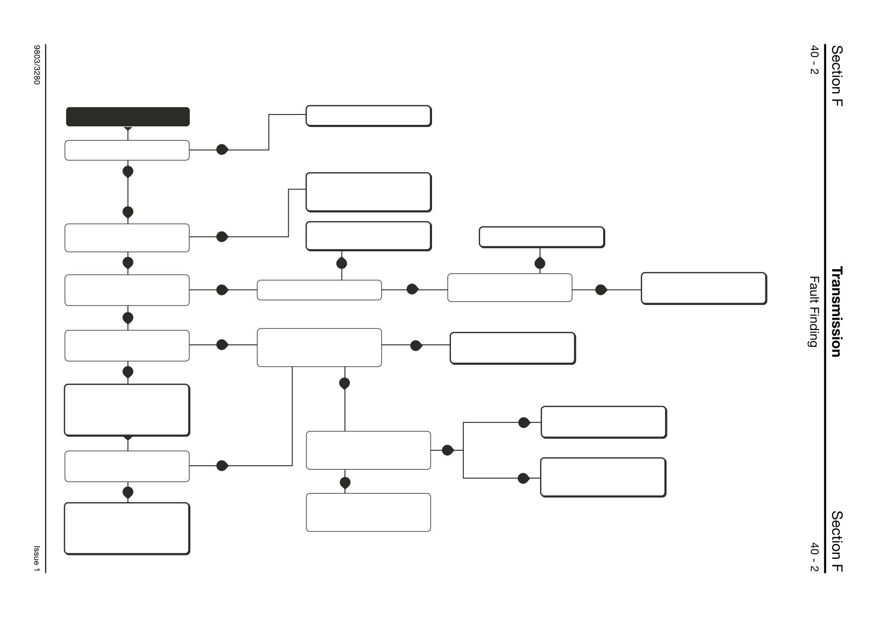
The fault finding procedures are given in the form of flow
charts. There are a number of charts, each one dedicated to
a particular fault. The charts are designed to identify
possible causes by performing checks and where
applicable, specific tests on the gearbox. Having identified a
cause the suggested remedy is given. The charts are
designed to identify causes through a process of elimination,
starting with the simplest, most easily rectified faults.
Gearbox faults may be caused by faulty electrical
*
connectors or components as indicated in the fault finding
charts. Full explanations of the relevant electrical systems
for both 4 speed and 6 speed (Shiftmaster) gearboxes are
given in Electrical Connections.
Due to the time and effort involved in removing, dismantling,
assembling and replacing a gearbox, it is recommended that
fault finding procedures are carried out until a fault can be
identified with a good degree of certainty.
Full details of the test procedures referred to in the charts
are given in Service Procedures, Powershift Gearbox.
Fault Finding Charts:
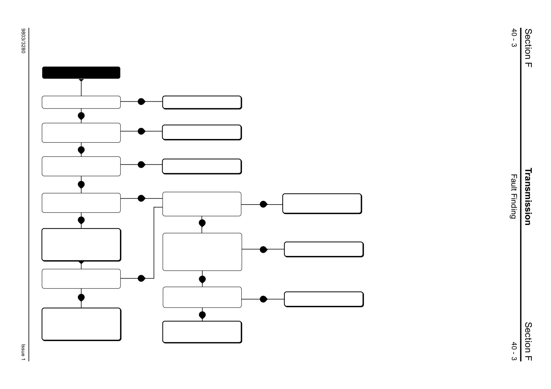
Chart A - Machine drives but lacks power in all gears.
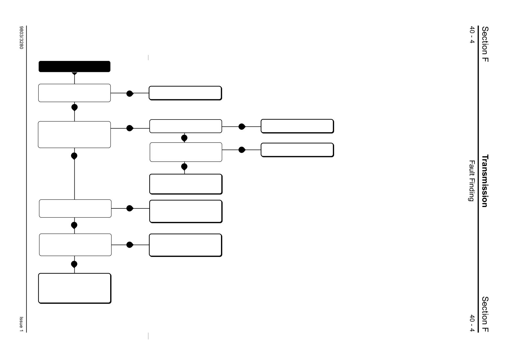
Gearbox oil may also be overheating.
Chart B - Machine does not drive in any gear.
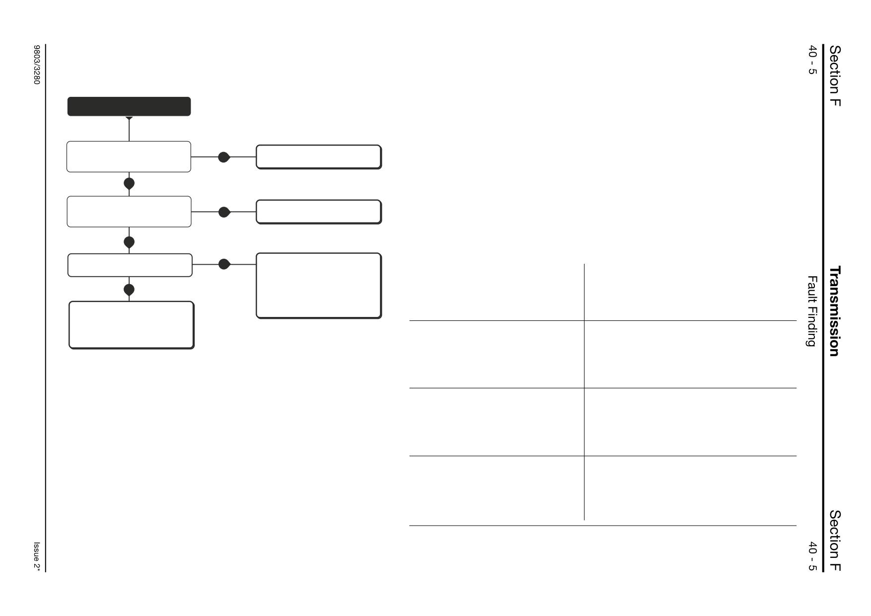
Chart C - Some gears fail to engage or lack power. 4WD
fails to engage.
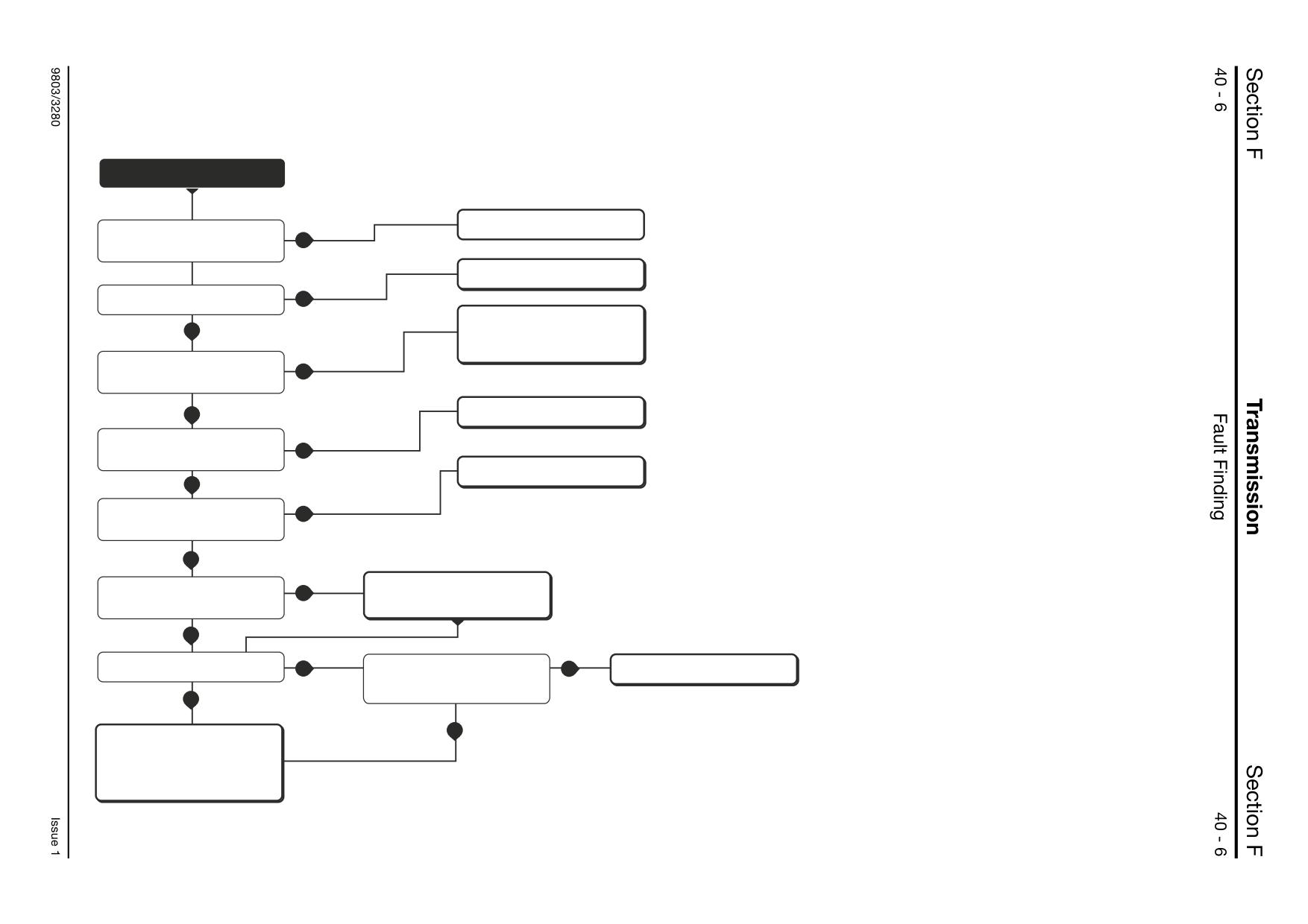
Chart D - (6 speed gearbox only) Shiftmaster fails to
function normally - fails to autoshift - shifts at
incorrect road speed.
Note: 4th, 5th and 6th gears utilise clutches used for 1st,
2nd and 3rd gears. If 4th, 5th or 6th gears fail to engage,
check that the lower 3 gears function correctly before
investigating a possible Shiftmaster fault. See Fault Finding
Chart C.
Chart E - Gearbox oil overheats
Chart F - External oil leakage
Chart G- Noisy operation
Further Fault Finding Information
Gearbox Oil Contaminated with Water
9803/3280
Issue 2*
Powershift Gearbox
Chart A - Machine drives but lacks power in all gears. Gearbox oil may also be overheating.
START
Top up oil level
Is gearbox oil level low?
YES
YES
Check reason for contamination.
Rectify as applicable Drain and flush
oil, see Flushing the Gearbox Oil.
NO
Is gearbox oil the correct type and
Check the operation of the parking
YES
Repair the engine as applicable.
and service brakes.
free from contamination?
YES
NO
NO
Torque converter reaction member
Carry out a Torque Converter Stall Test
Is the engine performance normal?
in all gears. Are all the stall speeds
YES
Are all the stall speeds too low?
YES
YES
clutch slipping. Remove the gearbox
See Checking the Engine Power.
and renew the torque converter.
outside specifications?
NO
Carry out Mainline Oil Pressure Test
Carry out Torque Converter In
Check condition of torque
YES
Pressure Test. Is torque converter in
NO
Is mainline oil pressure correct?
converter relief valve.
pressure correct?
Clean or renew as applicable.
NO
YES
Check condition of pressure
maintenance
valve. Clean or renew as applicable.
Check for signs of excessive external
Too high?
Cooler lines restricted or blocked. Oil
oil leakage.
YES
cooler blocked.
Carry out Torque Converter Out
Pressure Test. Is torque converter out
NO
Carry out Mainline Oil Pressure and
pressure correct?
Flow Tests
YES
Cooler lines or cooler leaking. Internal
Is mainline oil pressure /flow correct?
Too low?
leakage. Remove the gearbox, torque
YES
YES
converter housing and pump, check
all sealing faces for damage.
NO
It may be that another fault may have
Remove and dismantle gearbox.
been overlooked. Go back to the start
Check condition of pump, casings for
of the fault finding and re-check.
internal/external leakage. The clutches
will have been slipping due to low oil
pressure - dismantle all clutches and
A396280
renew as required.
Powershift Gearbox
Chart B - Machine does not drive in any gear.
START
Is gearbox oil level low?
YES
Top up oil level.
NO
Are the park brake and transmission
Renew switch or repair wiring as
NO
dump switches working correctly?
applicable.
YES
Is the gear selection column switch
working correctly. See Powershift
NO
Renew switch or repair wiring as
applicable.
Electrical System Tests.
NO
YES
Carry out Torque Converter In
Carry out Mainline Oil Pressure Test
Check condition of torque
Pressure Test
Is mainline oil pressure correct?
NO
converter relief valve.
Is torque converter in pressure
Clean or renew as applicable.
correct?
NO
YES
Check condition of pressure
Are the clutch control solenoids
maintenance
working? Check control valve
valve. Clean or renew as applicable.
solenoids for correct resistance
Renew solenoid or repair wiring as
Check for signs of excessive external
NO
and wiring continuity - check
applicable.
oil leakage.
forward and reverse solenoids
first.
Carry out Mainline Oil Pressure and
Flow Tests
YES
YES
Is mainline oil pressure /flow correct?
6 Speed - Is the gearbox ECU connected
correctly?
NO
NO
Clean connectors and fit securely.
4 Speed - Are the Powershift relays
connected correctly?
Remove and dismantle gearbox.
YES
Check condition of pump, casings for
internal/external leakage. Check
pump drive dogs on torque converter
6 Speed - Renew the ECU.
are undamaged.
4 Speed - Renew the relays as
applicable.
A396290
Powershift Gearbox
Chart C - Some gears fail to engage or lack power. 4WD fails to engage.
START
Are the gear selection column/4WD
Renew applicable switch or repair
switches working correctly. See
NO
wiring as applicable.
Powershift Electrical System Tests.
YES
Are the solenoids or associated
Renew applicable solenoid or repair
Are the relevant the clutch solenoids
YES
NO
wiring faulty.
wiring as applicable.
working? Identify the applicable
solenoids and check for correct
resistance and wiring continuity.
NO
6 Speed - Is the gearbox ECU connected
correctly?
NO
Clean connectors and fit securely.
YES
4 Speed - Are the Powershift relays
connected correctly?
YES
6 Speed - Renew the ECU.
4 Speed - Renew the relays as
applicable.
Carry out Individual Clutch Pressure
Clutch failure, jammed pistons or
Tests. Are the relevant clutch
YES
blocked oil ways: Remove and
pressures correct?
dismantle gearbox. Clear oilways,
renew clutches as applicable.
NO
Are the oilways clear at the control
Clear debris from ports. Replace valve
valve manifold and casing? -
manifold. If fault is cleared, flush
NO
Remove the manifold and check. See
gearbox oil. See Flushing the Gearbox
Removing the Control Valves.
Oil.
YES
Clutch Leakage: Remove and
dismantle gearbox. Check condition
of clutch piston seals, ball valves and
housings. Check shaft sealing rings
for wear or damage.
A396300
Powershift Gearbox
Chart D - (6 speed gearbox only) ShiftMaster fails to function normally - fails to autoshift - shifts at incorrect road speed.
Note: 4th, 5th and 6th gears utilise clutches used for 1st, 2nd and 3rd gears. If 4th, 5th or
START
6th gears fail to engage, check that the lower 3 gears function correctly before investigating
a possible ShiftMaster fault. See Fault Finding Chart C.
* The simplest and best way to fault find the 6 speed gearbox electrical system, (including the
Are the gear selection column
Renew the switch or repair wiring as
ECU) is by using ShiftMaster Diagnostics software and a laptop PC. See Diagnostics User
NO
switches, kickdown and throttle
applicable.
switches working correctly?
Guide. This diagnostics system enables the engineer to quickly identify faults with specific
electrical circuits or devices. The devices electrical connections, locations and wire
YES
identifications are given in Electrical Connections - Powershift Gearbox - 6 Speed. See
also Section C - Harness Data.
*
Is the speed sensor operating?
Renew sensor or repair wiring as
See Service Procedures - Powershift
NO
applicable.
Gearbox, Speed Sensor.
‘Limp Modes’
When applicable the ShiftMaster ECU provides restricted or modified gearbox operation if
YES
faults are detected by the ECU. Typical ‘Limp Mode’ forms of operation are:
Is the gearbox ECU connected
*
NO
correctly?
Clean connectors and fit securely.
Limp Mode 1
Possible Reason
Use ShiftMaster Diagnostics software
Machine autoshifts at different road
Internal ‘Setup Data’ ECU fault.
to check ECU inputs and outputs. See
YES
Service Procedures, Powershift
speeds than normal.
If on power-up the ECU detects an internal fault
Gearbox, Diagnostics User Guide.
2 Beeps at power-up.
with its ‘Setup Data’ it will revert to use of a
*
Renew the ECU.
default set of values.
See Service Procedures,
Powershift Gearbox, Electronic
A396310
Control Unit.
Limp Mode 2
Machine remains in neutral at all times.
Error with ECU ‘Application Software’.
1 Beep at power-up.
If on power-up the ECU detects an internal fault
with its ‘core operating software’ it will prevent
operation of the gearbox.
Limp Mode 3
Only 1st, 2nd, and 3rd gears available.
Error reading transmission speed.
Machine will not autoshift.
If the ECU does not detect any input from the
speed sensor it will prevent selection of any gear
above 3rd.
Limp Mode 4
Machine holds a gear.
Error reading transmission speed.
Repeating beeps until ECU power is
If the ECU detects an error with the speed
reset.
sensor whilst operating it prevents autoshifting.
Note: On power-up the ECU will normally sound 3 beeps. These beeps can be masked by
other audible warnings on start up.
Powershift Gearbox
Chart E - Gearbox oil overheats
START
Clean the matrix.
Is the gearbox oil cooler heat
exchanger matrix clogged with
YES
dirt/chaff?
Adjust oil to correct level.
Is gearbox oil level incorrect (too low
YES
or too high)?
Check reason for contamination.
NO
Rectify as applicable. Drain and flush
oil, see Flushing the Gearbox Oil.
Is gearbox oil the correct type and
free from contamination, especially
YES
water contamination?
Rectify routing/renew hoses as
NO
applicable
Are the cooler lines kinked, or
trapped?
YES
Educate operator.
NO
Is the machine being operated
NO
correctly - in the correct gear range?
YES
Carry out Torque Converter Out
Check condition of torque
NO
converter relief valve.
Pressure/Flow Test. Is the pressure
correct?
Clean or renew as applicable.
YES
YES
Is oil flow correct?
NO
Is the cooling circuit restricted or
YES
Rectify as applicable.
blocked internally? Remove cooler,
check lines and cooler for internal
YES
blockages.
NO
Remove gearbox. Check condition of
pump, casings for internal/external
leakage. Inspect clutches for signs of
jammed pistons. Repair clutches as
applicable.
A396320
Powershift Gearbox
Chart F - External oil leakage
START
Is the oil leaking from the gearbox or
from another source? Remember that
the main machine hydraulic pump is
YES
Rectify as applicable.
mounted on the gearbox. Oil leakage
from inside the torque converter
housing may be engine oil.
NO
Drain oil to correct level.
Is gearbox oil level too high?
YES
Check oil for water contamination.
NO
Is oil leaking from external, plugs,
adaptors, filter, pipes and hoses on
YES
Rectify as applicable.
the gearbox and cooling circuit?
NO
Remove valve manifold, check sealing
Is oil leaking from the solenoid control
faces for damage. Renew gaskets,
valve manifold/solenoid valve stem?
YES
solenoids and components as
applicable.
NO
Remove gearbox. Remove the torque
converter housing. Check the sealing
Is oil leaking between the torque
faces for signs of damage. Rectify as
converter housing to front case joint?
YES
applicable. Re-seal casings, See
Powershift Gearbox - Assembly step 10.
NO
Carefully check casings for signs of
damage. If damage is evident, remove
the gearbox and renew components
as required.
A396330
Powershift Gearbox
Chart G - Noisy operation
START
Is gearbox oil level low?
YES
Top up oil level.
NO
Check reason for contamination.
Is gearbox oil the correct type and
NO
Rectify as applicable Drain and flush
free from contamination?
oil, see Flushing the Gearbox Oil.
NO
Carry out a Lubrication Pressure
Test.
YES
Carry out Torque Converter Out
Is the pressure low?
Pressure Test. Is the pressure correct?
NO
NO
YES
Check the condition of the torque
converter relief valve. Make sure that
the cooler lines are not restricted.
Rectify as applicable.
Remove and dismantle gearbox.
Check all components for signs of
wear or damage, especially shaft
seals and bearings. Rectify as
applicable.
A396340
Section F
Transmission
Section F
40 - 9
Fault Finding
40 - 9
Powershift Gearbox
Gearbox Oil Contaminated with Water
Carefully inspect the gearbox oil for signs of water contamination. Contaminated oil will contain water droplets or be visibly
emulsified. Water droplets may be visible on the dipstick or inside the filler tube. For oil analysis purposes, the maximum
permissible water content of the oil is 0.10%.
If the gearbox oil has been contaminated with water, faults or damage to the gearbox may be apparent as a result. Before
remedying, thoroughly investigate and rectify the cause of the water contamination.
Note: The correct gearbox oil is given in Section 3, Service Capacities and Lubricants.
Possible Cause
Remedy
1
Water ingress during filling/topping up.
Carry out flushing procedure.
Refill with the correct oil, see Section 3,
2
Missing/incorrect dipstick, damaged filler tube.
Renew missing/incorrect/damaged components.
Carry out flushing procedure.
Refill with the correct oil, see Section 3,
3
Machine operated in deep water.
Carry out flushing procedure.
Refill with the correct oil, see Section 3,
4
Gearbox casings damaged.
Inspect, renew damaged components.
Carry out flushing procedure.
Refill with the correct oil, see Section 3,
5
Gearbox oil circuit pipes/hoses damaged.
Inspect, renew damaged components.
Carry out flushing procedure.
Refill with the correct oil, see Section 3,
Gearbox faults caused typically by water contamination and other factors related to the gearbox oil:
Fault
Possible Cause
Remedy
1
Pressurisation of gearbox
Water in oil combined with heat
Replace/renew dipstick.
casing - Dipstick blows out/oil
from torque converter causes
Carry out flushing procedure.
leaking from dipstick tube.
steam.
Refill with the correct oil, see Section 3,
Gearbox over filled with oil.
Drain the oil level to the correct level,
see Routine Maintenance - Checking
Transmission Oil Level.
2
Clutch Failure - Friction Lining
Water ingress.
Renew friction plates.
Separation.
Carry out flushing procedure.
Refill with the correct oil, see Section 3,
Overheating transmission oil.
See Fault Finding - Overheating.
3
Badly worn/noisy bearings.
Water ingress.
Fit new bearings.
Carry out flushing procedure.
Insufficient lubrication.
Refill with the correct oil, see Section 3,
9803/3280
Issue 1