JCB 3CX, 4CX, 214e, 214, 215, 217 & VARIANTS Backhoe Loader. Service Manual - page 22
Section F
Transmission
Section F
5-1
Technical Data
5-1
Powershift Gearbox - 6 Speed
Description
Full electro-hydraulic transmission unit with input, reverse,
layshaft, mainshaft, 6 speed and 4 wheel drive clutch packs
giving 6 forward and 4 reverse speeds. Electronically controlled
gear selection.
Designation
PS766 (4 wheel drive)
Weight (dry)
2WD
T.B.A.
4WD
T.B.A.
Gear Ratios
Forward
Reverse
1st
8.17:1
6.45:1
2nd
4.90:1
4.76:1
3rd
3.62:1
1.78:1
4th
2.25:1
1.31:1
5th
1.35:1
-
6th
1.00:1
-
Torque Converter
Torque Converter Dia.
310 mm (12.2 in.)
Torque Converter Identification
04/600580
04/600581
Torque Multiplication at Stall
2.52:1
3.01:1
Converter Pressures (in neutral)
bar
kgf/cm2
lbf/in2
Converter In at 50 ºC
1000 rev/min
2.0 - 4.95
2.0 - 5.0
29 - 72
2000 rev/min
4.0 - 6.8
4.1 - 6.9
58 - 99
Converter Out at 50 ºC
1000 rev/min
0.6 - 2.25
0.6 - 2.3
8.7 - 33
2000 rev/min
1.25 - 2.50
1.3 - 2.6
18 - 36
Converter Inlet Relief Valve Pressure (max.)
7.1
7.2
103
Lubrication Pressures (in neutral)
At 50 ºC
1000 rev/min
0.25 - 1.0
0.26 - 1.0
3.6 - 14.5
2000 rev/min
0.50 - 1.0
0.51 - 1.0
7.3 - 14.5
Main Line Pressure (in neutral)
At 50 ºC
1000 rev/min
11.4 - 15.7
11.6 - 16.0
165 - 228
2000 rev/min
12.4 - 17.0
12.6 - 17.3
180 - 246
Flow Rates (in neutral)
L/min
US gal/min
UK gal/min
Cooler at 50 ºC
1000 rev/min
14.0 MIN
3.7 MIN
3.1 MIN
2000 rev/min
17.0 MIN
4.5 MIN
3.7 MIN
Pump at 50 ºC
1000 rev/min
16.0 MIN
4.2 MIN
3.5 MIN
2000 rev/min
34.0 MIN
9.0 MIN
7.5 MIN
* Control Solenoid Valves
3 way, 2 position, normally closed, integral suppression diode.
Coil Resistance
7.5 Ohm @ 20 ºC
9803/3280
Issue 2*
Section F
Transmission
Section F
6 - 1
Technical Data
6 - 1
Powershift Gearbox - 4 Speed
Description
Full electro-hydraulic transmission unit with input, reverse,
layshaft, mainshaft and 4 wheel drive clutch packs giving 4
forward and 4 reverse speeds.
Designation
PS764 (4 wheel drive)
Weight (dry)
2WD
T.B.A.
4WD
T.B.A.
Gear Ratios
1st
7.97:1
2nd
4.29:1
3rd
1.86:1
4th
1.00:1
Torque Converter
Torque Converter Dia.
310 mm (12.2 in.)
Torque Converter Identification
04/600580
04/600581
Torque Multiplication at Stall
2.52:1
3.01:1
Converter Pressures (in neutral)
bar
kgf/cm2
lbf/in2
Converter In at 50 ºC
1000 rev/min
2.0 - 4.95
2.0 - 5.0
29 - 72
2000 rev/min
4.0 - 6.8
4.1 - 6.9
58 - 99
Converter Out at 50 ºC
1000 rev/min
0.6 - 2.25
0.6 - 2.3
8.7 - 33
2000 rev/min
1.25 - 2.50
1.3 - 2.6
18 - 36
Converter Inlet Relief Valve Pressure (max.)
7.1
7.2
103
Lubrication Pressures (in neutral)
At 50 ºC
1000 rev/min
0.25 - 1.0
0.26 - 1.0
3.6 - 14.5
2000 rev/min
0.50 - 1.0
0.51 - 1.0
7.3 - 14.5
Main Line Pressure (in neutral)
At 50 ºC
1000 rev/min
11.4 - 15.7
11.6 - 16.0
165 - 228
2000 rev/min
12.4 - 17.0
12.6 - 17.3
180 - 246
Flow Rates (in neutral)
L/min
US gal/min
UK gal/min
Cooler at 50 ºC
1000 rev/min
14.0 MIN
3.7 MIN
3.1 MIN
2000 rev/min
17.0 MIN
4.5 MIN
3.7 MIN
Pump at 50 ºC
1000 rev/min
16.0 MIN
4.2 MIN
3.5 MIN
2000 rev/min
34.0 MIN
9.0 MIN
7.5 MIN
*
Control Solenoid Valves
3 way, 2 position, normally closed, integral suppression diode.
Coil Resistance
7.5 Ohm @ 20 ºC
9803/3280
Issue 2*
Section F
Transmission
Section F
7 - 1
Technical Data
7 - 1
Engine Stall Speed Combinations
The stall speed figures on the following pages are intended as a guide to assist with machine fault diagnosis. The figures relate to
tests conducted at an ambient of 25 deg. C and barometric pressure of 100 kPa (sea level). Note that changes in ambient
temperature, pressure and humidity and fuel grade will affect engine power and hence the stall figures.
As an example, at 10,000 ft the power reduction of a naturally aspirated engine could be 29% and for a turbo engine 8%.
9803/3280
Issue 1
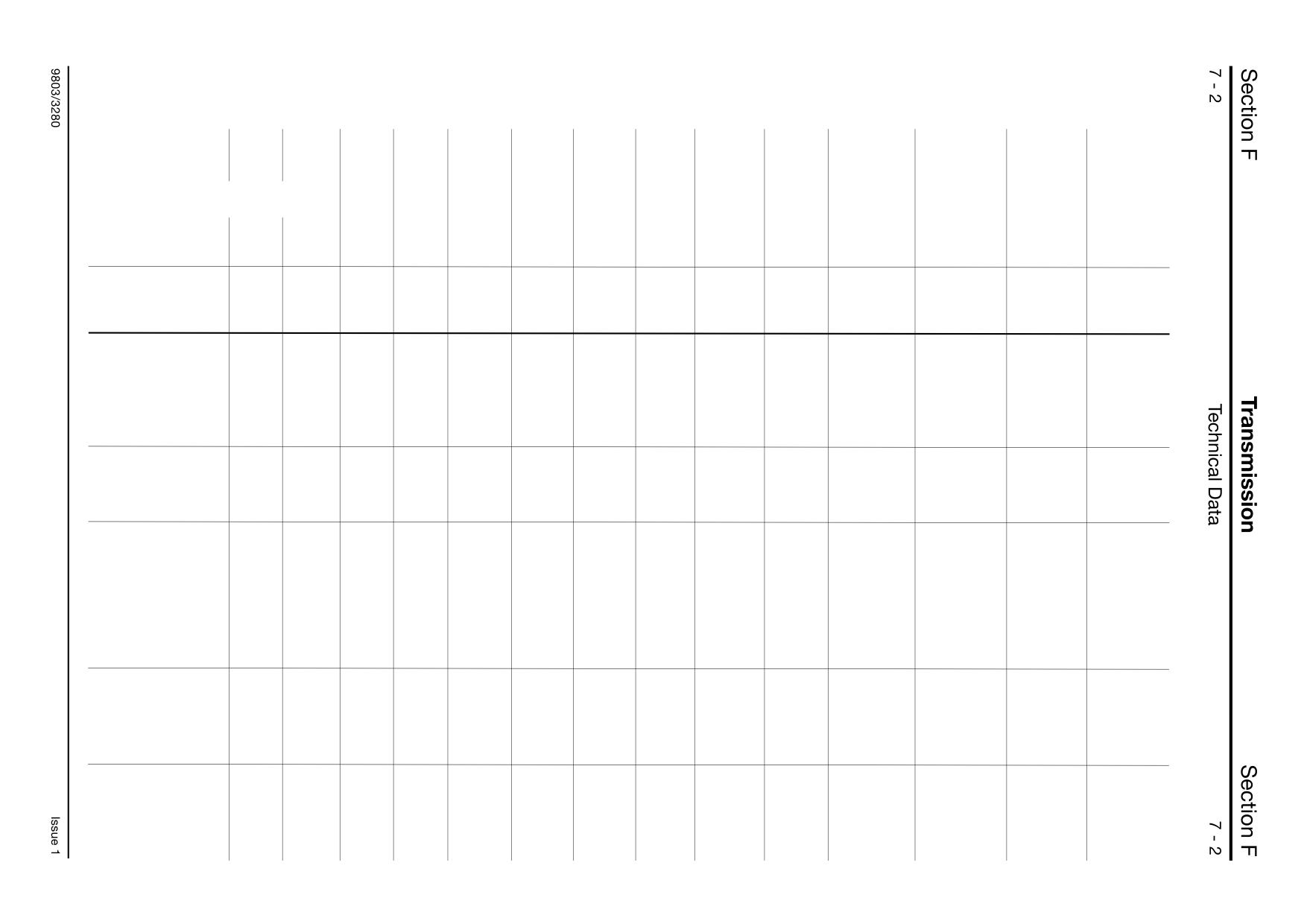
Engine Stall Speed Combinations - Two wheel steer (2WS) machines, Low emission 1000 series engine
Note. On all double pump options the test is to be carried out with single pump option selected.
3CX
3CX
3CXT
3CXT
3CXT
3CXT
3CX
3CX
Std. Lft
Std. Lft
Hi. Lft
Hi Lft
Contra
Contra
Engine Speed @ Stall Combination
1.Convertor only.
Max.r.p.m.
2160
2150
2150
2140
2140
2130
2190
2190
Min.r.p.m.
2060
2040
2045
2035
2035
2025
2100
2090
2.Convertor + M.R.V.
Max.r.p.m.
1700
1690
1805
1800
1745
1735
1835
1825
Min.r.p.m.
1550
1530
1665
1655
1590
1585
1700
1690
Build specification.
Engine size.
N.A. (75hp) (56kw)
O
O
T2 (92hp) (69kw)
O
O
O
O
T3 (100hp) (75kw)
O
O
Convertor type.
W300 (3.01)
O
O
W300 (2.52)
O
O
O
O
O
O
Pump size.
29 + 23cc
33/23cc
O
O
36/26cc
O
O
41/26cc
O
O
O
O
41/29cc
74cc variable
Fan Ratio.
1 to 0.85
O
1 to 1.06
O
O
O
O
1 to 1.16
O
O
O
Air Conditioning
None
O
O
O
O
Europe
O
O
O
O
R.O.W.
O
O
O
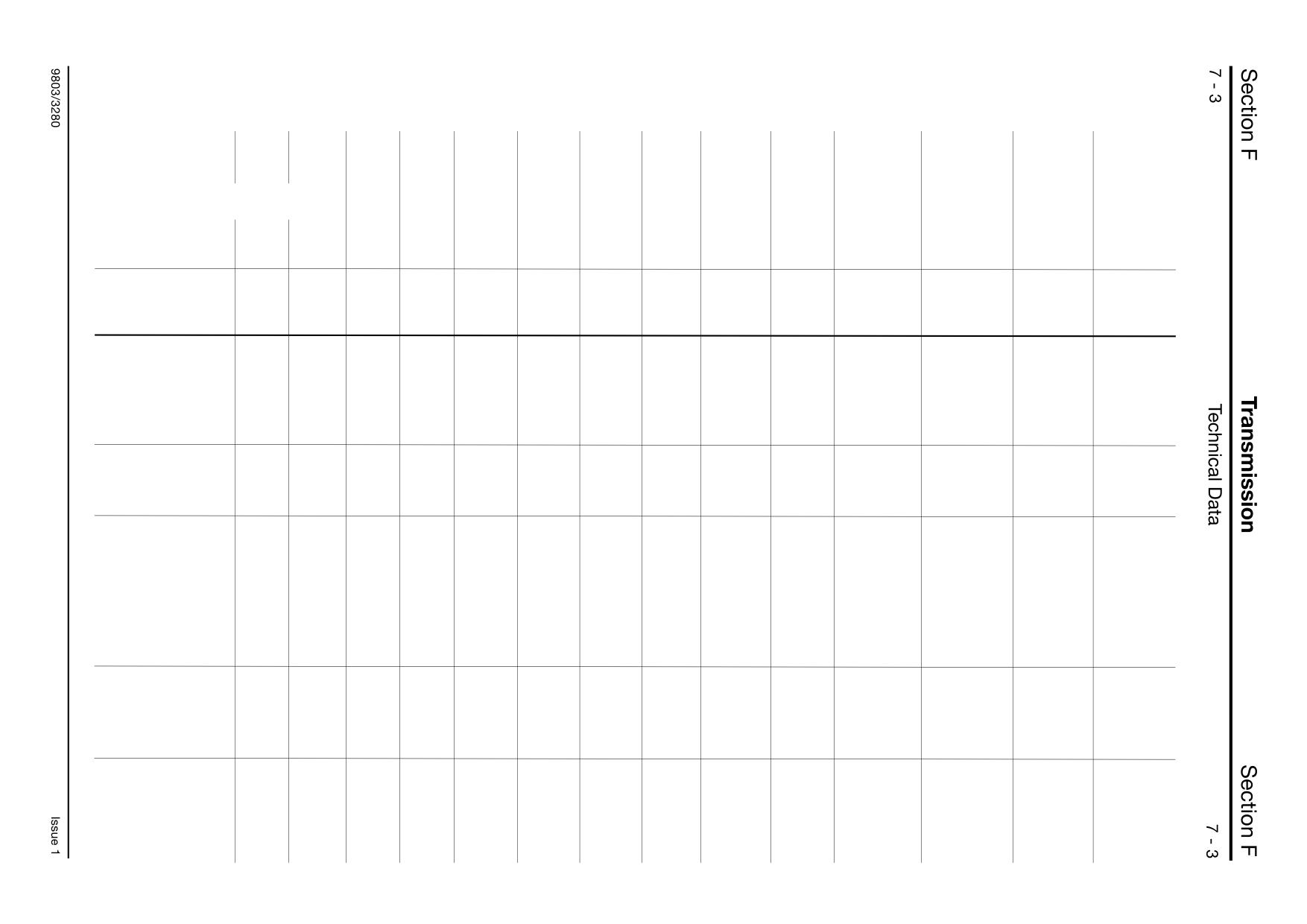
Engine Stall Speed Combinations - All wheel steer (AWS) machines, Low emission 1000 series engine
Note. On all double pump options the test is to be carried out with single pump option selected.
3CX
3CX
3CX
3CX
4CX
4CX
4CX
4CX
4CX
4CX
Super
Super
Super
Super
Super
Super
Super
Super
Std. Lft
Std. Lft
Hi. Lft
Hi. Lft
4C
4C
4CX
4CX
Engine Speed @ Stall Combination
1.Convertor only.
Max.r.p.m.
2150
2140
2140
2130
2190
2190
2200
2190
2235
2230
Min.r.p.m.
2045
2035
2035
2025
2100
2090
2095
2090
2140
2130
2.Convertor + M.R.V.
Max.r.p.m.
1805
1800
1745
1735
1835
1825
1825
1820
N/A
N/A
Min.r.p.m.
1665
1655
1590
1585
1700
1690
1685
1685
N/A
N/A
Build specification.
Engine size.
N.A. (75hp) (56kw)
T2 (92hp) (69kw)
O
O
O
O
T3 (100hp) (75kw)
O
O
O
O
O
O
Convertor type.
W300 (3.01)
W300 (2.52)
O
O
O
O
O
O
O
O
O
O
Pump size.
29 + 23cc
33/23cc
36/26cc
O
O
41/26cc
O
O
O
O
41/29cc
O
O
74cc variable
O
O
Fan Ratio.
1 to 0.85
1 to 1.06
O
O
O
O
O
1 to 1.16
O
O
O
O
O
Air Conditioning
None
O
O
O
O
O
Europe
O
O
O
O
O
R.O.W.
O
O
O
O
O
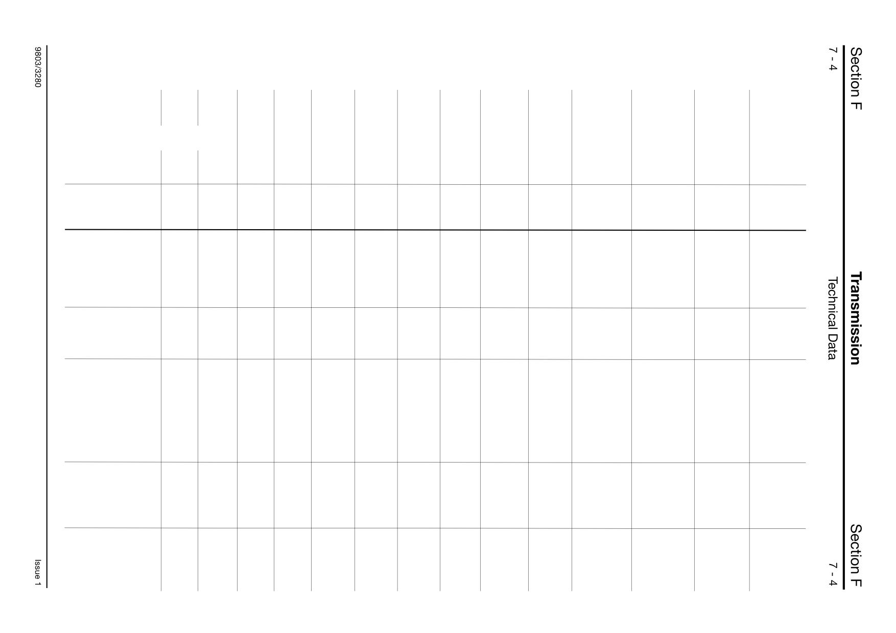
Engine Stall Speed Combinations - Two wheel steer (2WS) machines, Low emission 1000 series engine, (North America)
Note. On all double pump options the test is to be carried out with single pump option selected.
214E
214e
214
214
215E
215E
214T
215
214T
214T
217
Engine Speed @ Stall Combination
1.Convertor only.
Max.r.p.m.
2130
2130
2160
2140
2270
2270
2190
2190
Min.r.p.m.
2020
2020
2060
2025
2170
2160
2090
2090
2.Convertor + M.R.V.
Max.r.p.m.
1330
1330
1700
1685
1870
1865
1825
1820
Min.r.p.m.
970
970
1550
1520
1720
1715
1690
1685
Build specification.
Engine size.
N.A. (75hp) (56kw)
O
O
O
O
T2 (92hp) (69kw)
O
O
T3 (100hp) (75kw)
O
O
Convertor type.
W300 (3.01)
O
O
O
O
O
O
W300 (2.52)
O
O
Pump size.
29 + 23cc
O
O
33/23cc
O
O
36/26cc
41/26cc
O
O
O
41/29cc
O
74cc variable
Fan Ratio.
1 to 0.85
O
O
O
1 to 1.06
O
1 to 1.16
O
O
O
O
Air Conditioning
None
O
O
O
O
O
O
Air Con.
O
O
O
O
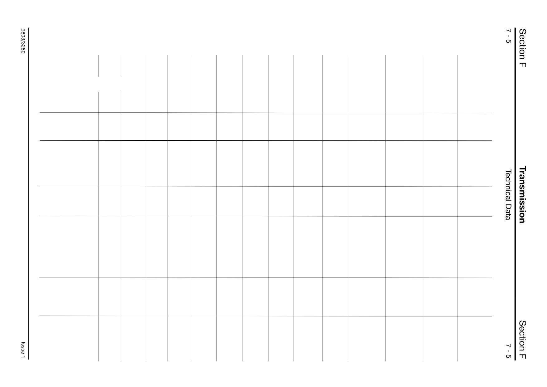
Engine Stall Speed Combinations - All wheel steer (AWS) machines, Low emission 1000 series engine, (North America)
Note. On all double pump options the test is to be carried out with single pump option selected.
214S
215S
217S
Engine Speed @ Stall Combination
1.Convertor only.
Max.r.p.m.
2190
2190
Min.r.p.m.
2090
2090
2.Convertor + M.R.V.
Max.r.p.m.
1825
1820
Min.r.p.m.
1690
1685
Build specification.
Engine size.
N.A. (75hp) (56kw)
T2 (92hp) (69kw)
T3 (100hp) (75kw)
O
O
Convertor type.
W300 (3.01)
W300 (2.52)
O
O
Pump size.
29 + 23cc
33/23cc
36/26cc
41/26cc
O
41/29cc
O
74cc variable
Fan Ratio.
1 to 0.85
1 to 1.06
1 to 1.16
O
O
Air Conditioning
None
O
O
Air Con.
O
O
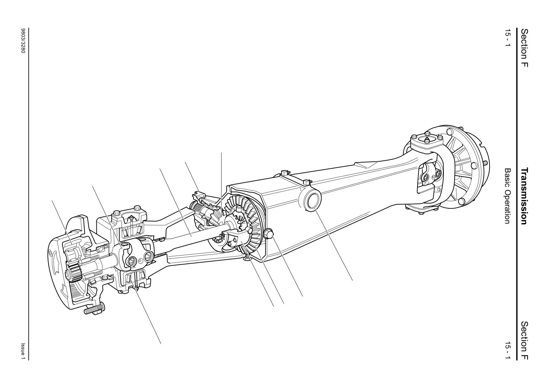
Front Axle - Steer Drive Type SD55, SD70
Component Identification
The illustration shows a typical steer drive front axle.
A Yoke connection to propshaft
B Pinion
C Crownwheel
D Differential unit
E Drive shaft
F Universal coupling
G Reduction gear hub
H Steer swivel trunnion bearings
J Axle pivot
K Oil fill and drain plugs
B
A
E
F
G
J
K
C
D
H
A355950
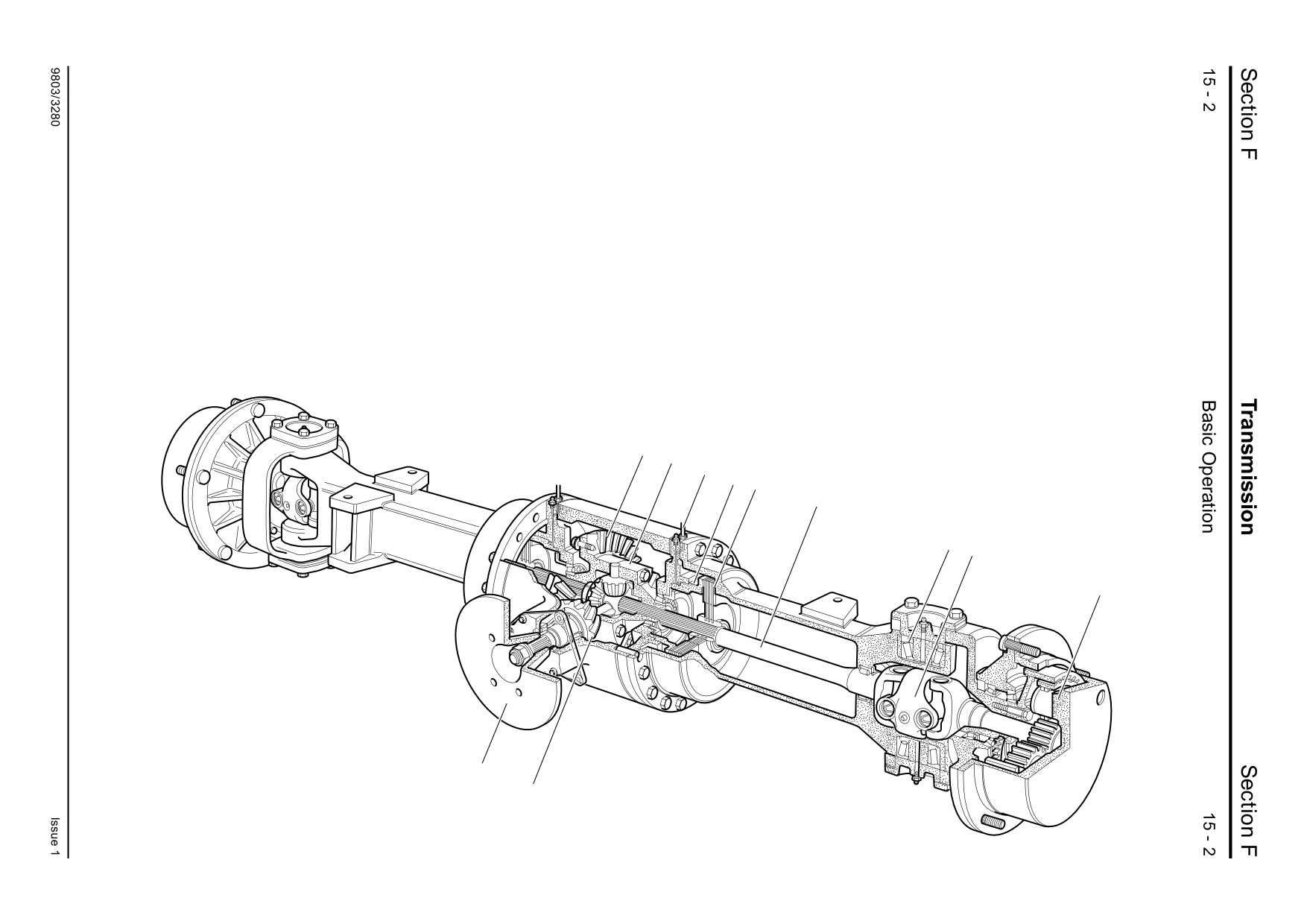
Rear Axle - Steer Drive Type SD80
Component Identification
The illustration shows a typical steer drive rear axle. 2WS
A Park brake disc. The disc is fitted to the pinion instead of a yoke. The propshaft is bolted to the
machines are fitted with non steer axles (PD70). These axles
centre of the disc. The axle casing also carries a bracket for location of the park brake caliper.
are similar to the axle shown but do not feature steer swivels
B Pinion
or drive shaft universal joints.
C Crownwheel
D Differential unit
Note: Items A, B, C, and D form the ‘drive head’ part of the axle.
E Drive shaft
F Universal coupling
G Reduction gear hub
H Steer swivel trunnion bearings
L In-board oil immersed multi-plate disc brakes
M Brake actuating piston
N Hydraulic brake lines
C
D
N
M
L
E
H F
G
A
B
A396760
R
Synchro Shuttle Gearbox
E
T
A
B
S
D
Q
K
W
V
C
N
G
F
J
M
H
A388431
U
P
X
L
Y
A396620
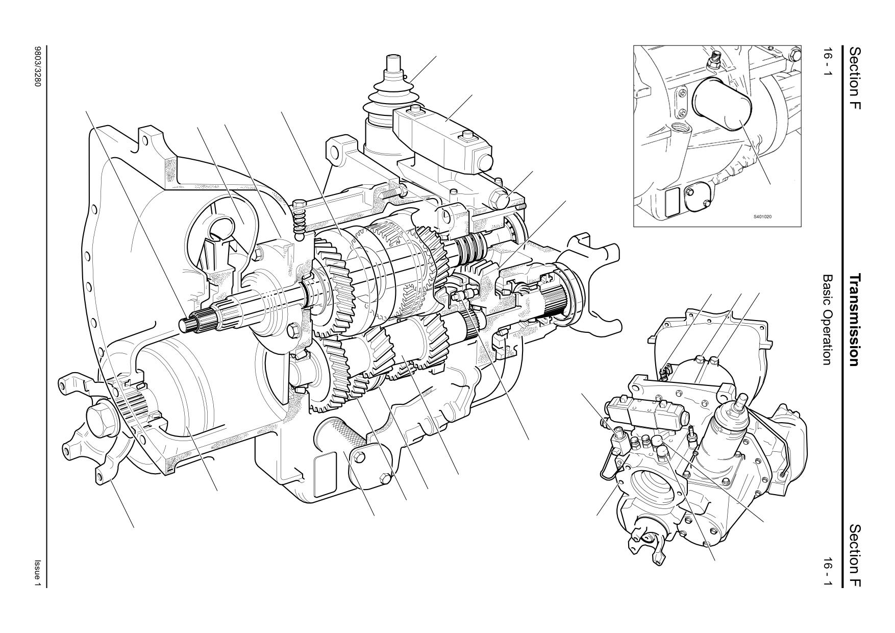
Synchro Shuttle Gearbox
Component Identification
Principle of Operation
A
Forward/reverse clutch unit
This Illustration shows a typical JCB Syncro Shuttle
B
Transmission oil pump
which consists of a torque converter, hydraulic
C
Torque converter pressure regulating valve
reverser unit, and integral manual 4-speed gearbox.
D
Oil pressure maintenance valve
E
Solenoid control valve
The reverser unit A has a pair of hydraulically
F
Mainshaft
operated clutches giving forward - neutral - reverse
G
Synchromesh unit - 3rd/4th gears
drive. Oil pressure is provided by a crescent type
H
Layshaft
pump B driven at engine speed by the drive lugs of
the torque converter. The oil pressure is controlled
J
Synchromesh unit - 1st/2nd gears
by maintenance valve D, and clutch selection is
K
Transfer gear, output shaft and yoke
achieved by means of an electric solenoid valve E.
L
4WD output yoke (if fitted)
M
2/4WD clutch unit (if fitted)
Drive is transferred from the reverser unit by helical
N
4WD solenoid control valve (if fitted)
gears to the mainshaft F, which carries the 3rd/4th
Z
P
Oil strainer
synchromesh unit G, and to the layshaft H, which
Q
Oil filter
A401330
carries the 1st/2nd synchromesh unit J.
R
Gear selection turret assembly
Synchromesh unit G is of the 'Blocking Pin' type, a
S
Torque Converter
full description of which is given in this section.
T
Driveshaft (drives machine main hydraulic
Synchromesh unit J features rings and cones with a
pump)
sliding sleeve.
U
Hydraulic pump mounting face
V
Torque converter relief valve
Drive is transmitted finally via the output shaft K to
W Oil pressure switch
the rear axle. If 4 wheel drive is selected, the front
X
Hose connection - to cooler
wheels are also driven via 4 wheel drive output
Y
Hose connection - from cooler
yoke L.
Z
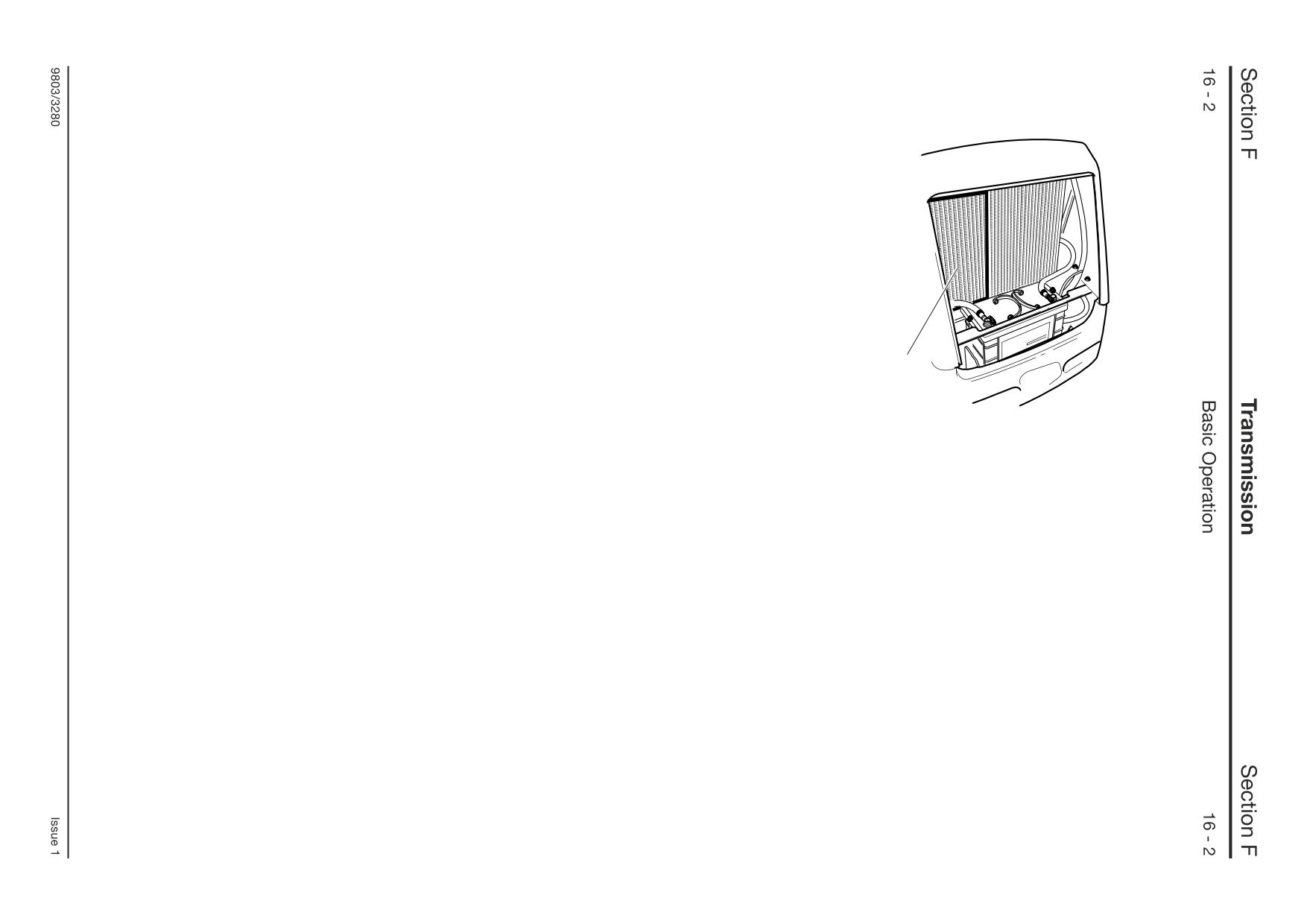
Gearbox oil cooler
Driveshaft T is permanantly driven by the engine
and runs through the hollow forward/reverse unit
shaft to the back of the gearbox. The shaft (T)
drives the gearbox mounted machine main
hydraulic pump.
Gearbox oil is cooled by an air blast cooler Z. The
cooler is part of the front mounted machine ‘cooling
pack’.
D
V
F
B C
E
Q
S
E1
Z
A A1
A2
E2
N
K
A3
A4
Key to Oil Flow & Pressure
Full Pressure
Pressure
Lubrication
Exhaust
L
M
A396520
P
Synchro Shuttle Gearbox
Hydraulic and Electrical Operation
Key
Oil from the pump B is fed through an internal
Solenoid Valve (E) Operation
passage via the filter to the pressure maintenance
Pressurised oil at the solenoid valve E is used to
A
Forward/reverse clutch unit
valve D, which maintains pressure to the solenoid
control the forward/reverse clutches A1 and A2.
A1
Forward clutch
valve E for clutch selection. Excess oil from the
Forward:
A2
Reverse clutch
maintainance valve flows back through the casing
A3
Forward/reverse front shaft
In the diagram, electrical solenoid E1 is energised
to the torque converter S. Oil enters the converter
A4
Forward/reverse front shaft bearing
by the forward/reverse control lever in the cab.
between the converter hub and the stator support,
Pressurised oil is diverted to the forward clutch A1
B
Transmission oil pump
and leaves between the stator and the input shaft.
C
Torque converter pressure regulating valve
and forward is selected. A restrictor orifice in the
Pressure in the converter is controlled by a
feed to the solenoid valve modulates the pressure
D
Oil pressure maintenance valve
regulating valve C which dumps oil from the
to the clutch to smooth engagement. At the same
E
Solenoid control valve
converter line back to the sump.
time oil from reverse clutch A2 is diverted back to
F
Idler gear bearing
the sump via solenoid valve E.
K
Output shaft bearing
Torque converter relief valve V acts as a safety
L
4WD output yoke (if fitted)
valve should the system pressure suddenly rise
Reverse:
M
2/4WD clutch unit (if fitted)
obove normal, protecting the torque converter from
When the reverse is selected electrical solenoid E2
N
4WD solenoid control valve (if fitted)
being damaged.
is energised and pressurised oil is diverted to the
P
Oil strainer
reverse clutch A2. At the same time oil from clutch
Q
Oil filter
Oil from the torque converter S flows out of the
A1 is diverted back to the sump
S
Torque Converter
transmission to the external oil cooler Z, returning
Neutral:
V
Torque converter relief valve
at the rear of the transmission unit to pass through
When neutral is selected (via the control lever or the
Z
Oil Cooler
the centre of the reverser shaft for clutch
transmission dump button), the flow of the
lubrication.
pressurised oil is blocked at the solenoid valve. No
solenoids are energised and no clutches engaged.
Lubrication oil is also provided via a pump drain
line to the forward/reverse front shaft bearing A4.
For a further detailed description refer to
The drain from pressure maintenance valve D also
Forward/Reverse Clutch - Operation.
provides lubrication for idler gear bearing F.
The 2/4WD unit M is controlled by solenoid valve N.
For a full description of 2/4 wheel drive clutch
operationrefer to 2/4WD Clutch Operation.
A
J
3
2
B
C
D
R
5
N
G
A401080
L
F
Q
H
A401070
C
E
K
P
M
1
Powershift Gearbox
Component Identification
Principle of Operation
A
Torque converter
The JCB Powershift is an electro-hydraulic
B
Forward/input clutch assembly
transmission unit. Gear shifting and direction
C
Reverse clutch assembly
selection are controlled using multi-disc clutch
D
Mainshaft assembly
packs.
E
Layshaft assembly
F
2/4 wheel drive clutch assembly
Electrically operated solenoid valves 5 divert
G
Torque converter relief valve
pressurised oil (provided by pump J) to the
H
Oil pressure maintenance valve
selected clutch packs.
J
Transmission oil pump
A combined lever/swivel switch 4 on the steering
K
6 speed assembly (if fitted)
column actuates both gear ratio and direction
L
4WD output yoke
solenoids.
M
Hose connection - to oil cooler
6
N
Hose connection - from oil cooler
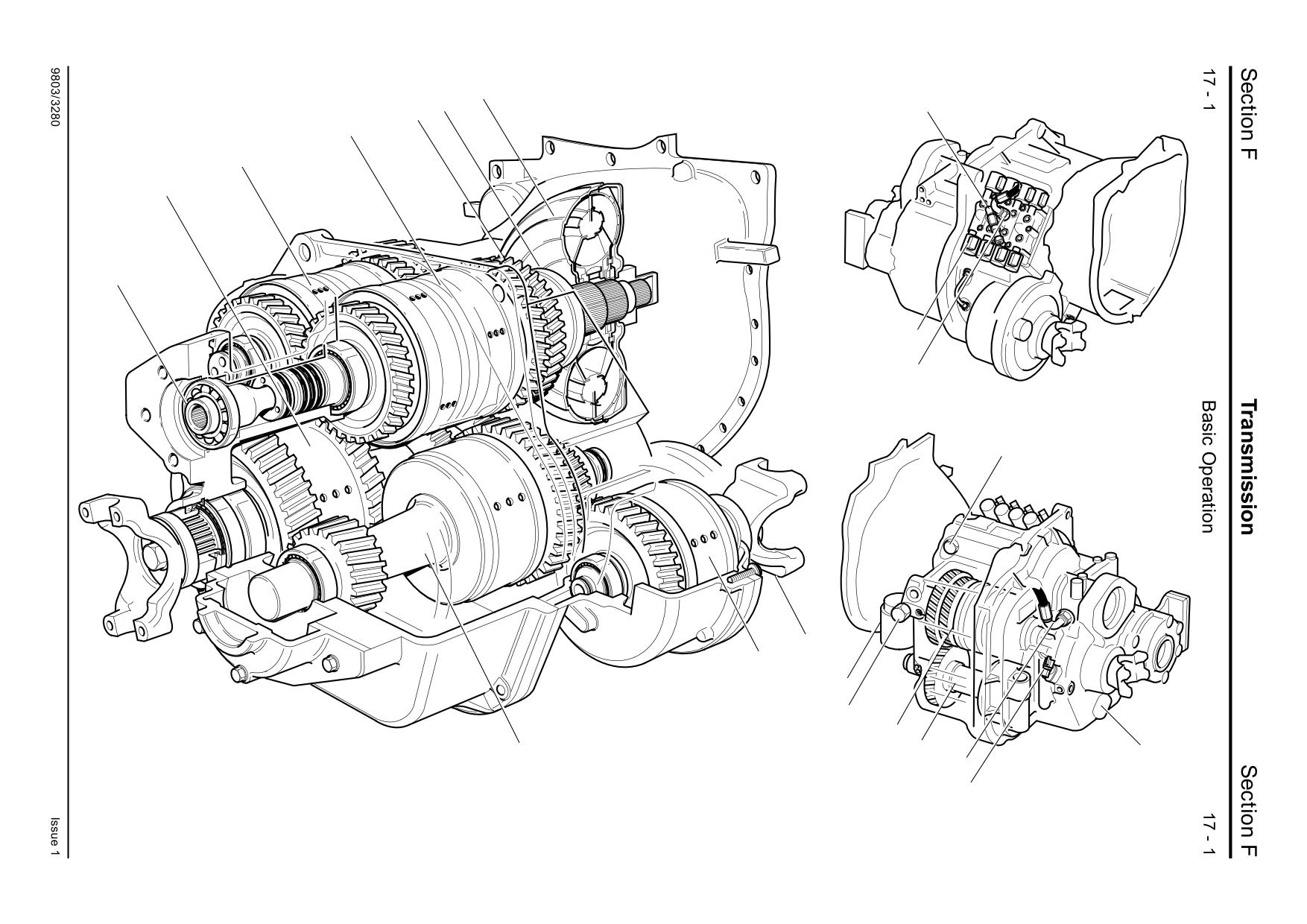
The Powershift unit consists of a torque converter
P
Oil strainer
A401330
A, forward clutch assembly B, reverse clutch
Q
Oil filter
assembly C, layshaft assembly E, mainshaft
R
Driveshaft (drives machine main hydraulic
4
assembly D, 2/4 wheel drive clutch assembly F.
pump)
6 speed gearboxes incorporate a ‘6 speed’ shaft
and clutch assembly K.
1
Speed sensor
2
Gear drive to reverse unit clutch assembly
The forward clutch assembly B is driven by the
3
Transmission oil pressure switch
torque converter A. The reverse clutch assembly C
4
Steering column mounted gear selection switch
is permanently driven via constant meshing of spur
5
Solenoid control valves
gears 2. On 6 speed gearboxes the 6 speed
6
Gearbox oil cooler
assembly is also driven via meshing gears 2.
Driveshaft R is permanently driven by the engine
and runs through the hollow forward/reverse unit
shaft to the back of the gearbox. The shaft (R)
drives the gearbox mounted machine main
hydraulic pump.
Strainer P and filter Q are used to prevent potential
system contamination by filtering dirt particles.
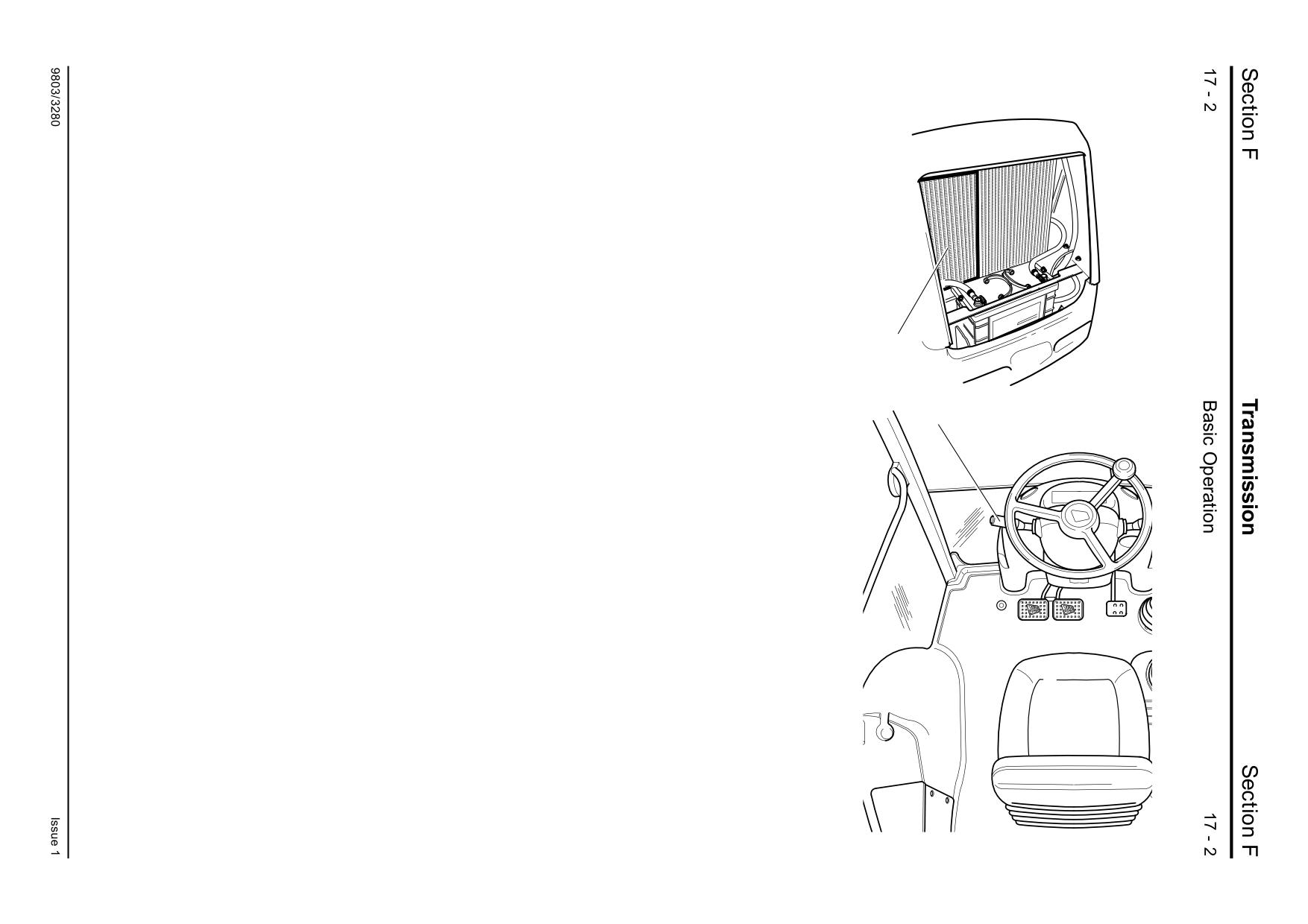
Gearbox oil is cooled by an air blast cooler 6. The
cooler is part of the front mounted machine ‘cooling
pack’.
Section F
Transmission
Section F
17 - 3
Basic Operation
17 - 3
H
G
K
2
1
3
2
3
Xs
1
5
C
Q
A
Us
J
Ts
Ss
1
B
R
M
Ws
6
Vs
D
Ys
L
E
Zs
P
N
F
9803/3280
Issue 1
Section F
Transmission
Section F
17 - 4
Basic Operation
17 - 4
Powershift Gearbox
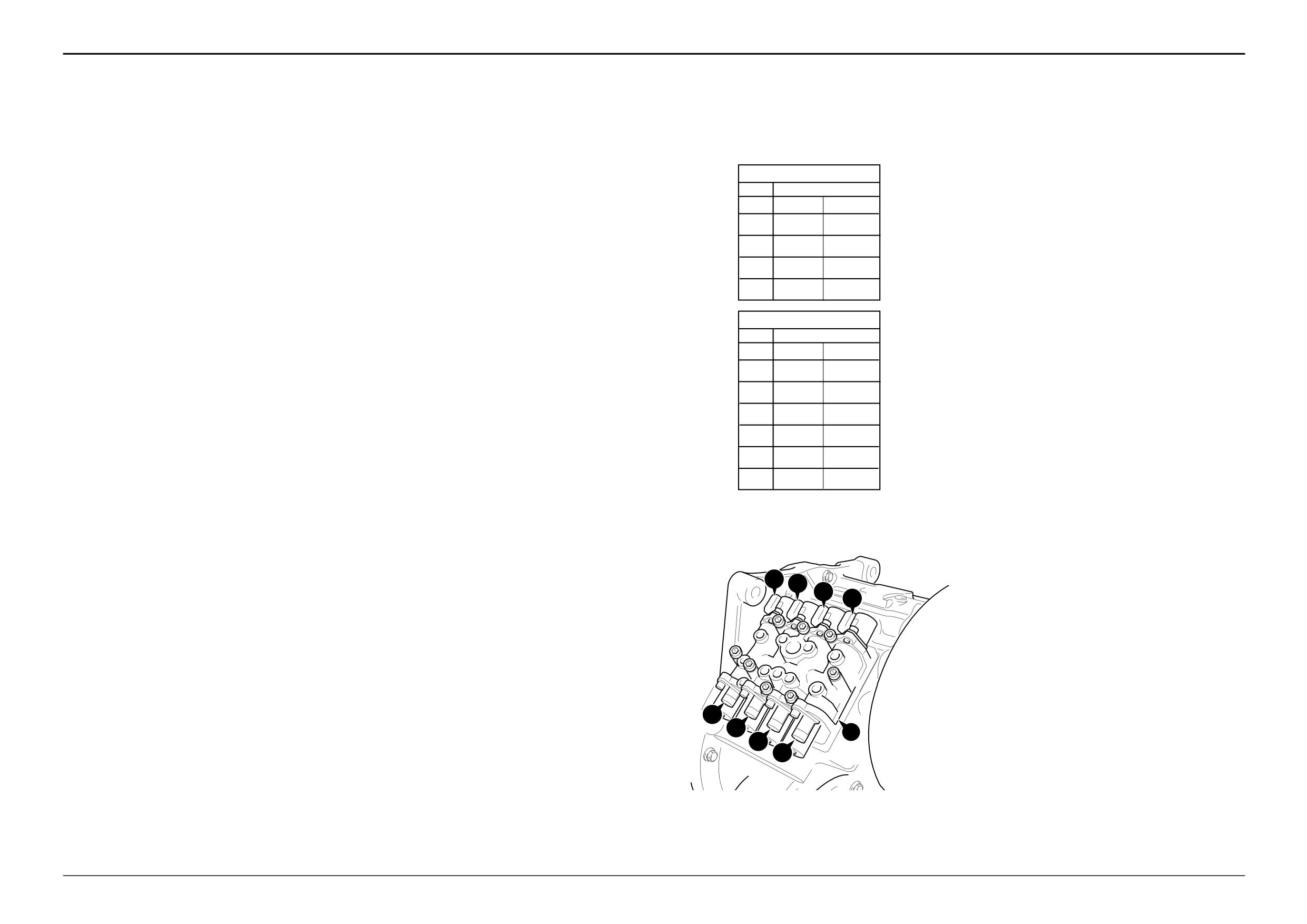
Hydraulic and Electrical Operation
Key
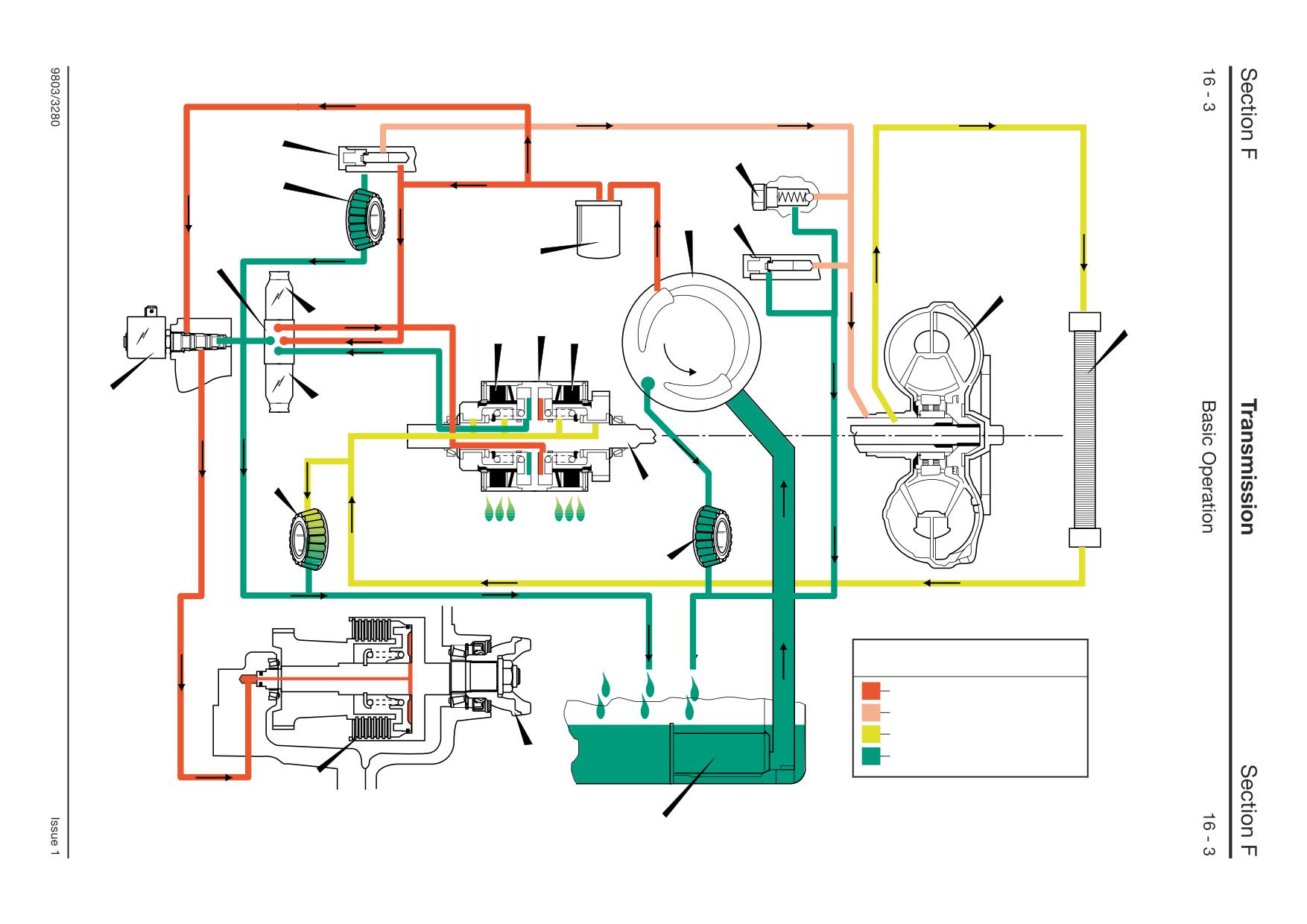
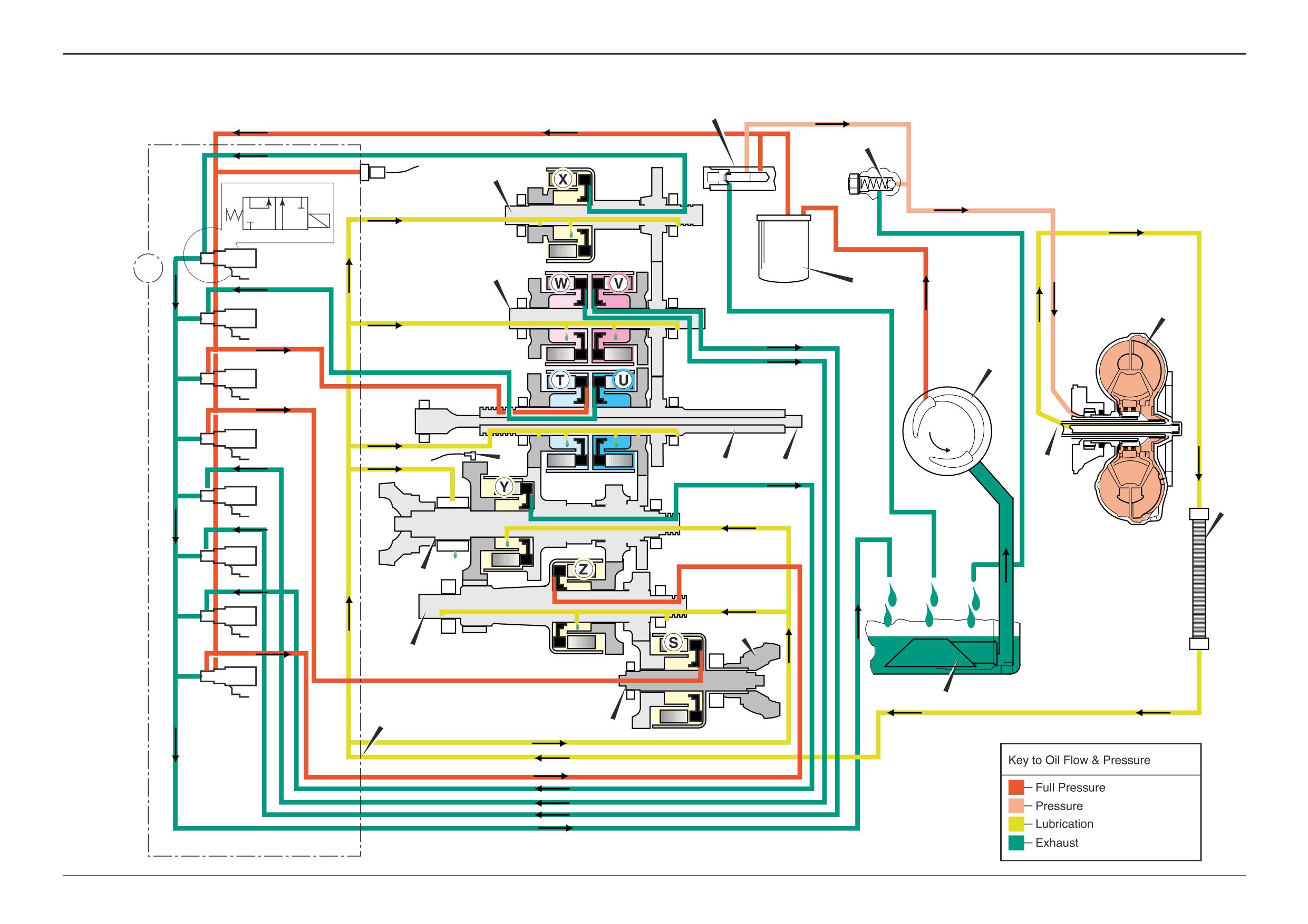
Oil pump J is directly driven by the engine via the torque
The 2/4 wheel drive unit F also has a single clutch S. When
4 Speed Powershift
converter.
4WD is selected, pressurised oil is directed via solenoid
A
Torque converter
Gear
Clutches engaged
valve Ss to the 4WD clutch. When 2WD is selected a
B
Forward clutch assembly
Oil from the pump J is fed through an internal passage via
connection from the clutch to the transmission sump is
Forward
Reverse
C
Reverse clutch assembly
the filter Q to the pressure maintenance valve H, which
made. For a full description of 2/4 wheel drive clutch
1st
T,Z
W,Z
D
Mainshaft assembly
maintains pressure to the solenoid valve block for clutch
operation see Systems Description, 2/4WD Clutch
E
Layshaft assembly
selection. Excess oil from the maintainance valve flows
Operation
2nd
U,Z
V,Z
F
2/4 wheel drive clutch assembly
back through the casing to the torque converter A.
G
Torque converter relief valve
Pressure in the converter is controlled by a relief valve G
When a gear is selected via the control switch in the cab, 2
3rd
T,Y
W,Y
H
Oil pressure maintenance valve
which dumps oil from the converter line back to the sump.
clutches are always engaged. By selecting different pairs of
J
Transmission oil pump
clutches different gear ratios are engaged. On 4 speed
4th
U,Y
V,Y
Oil from the torque converter A flows out of the gearbox at
K
6 speed assembly (if fitted)
gearboxes the solenoids are electrically controlled using
position M to the external oil cooler 6, returning to the
L
4WD output yoke
relays. On 6 speed gearboxes the solenoids are controlled
solenoid valve manifold block 5 at position N. The oil then
6 Speed Powershift
M
Hose connection - to oil cooler
by an electronic control unit (ECU) mounted in the cab.
flows through internal oilways providing lubrication for
N
Hose connection - from oil cooler
Speed sensor 1 is used to enable the gear selection to be
Gear
Clutches engaged
clutches and bearings before returning to the gearbox
P
Oil strainer
managed automatically as required.
sump.
Forward
Reverse
Q
Oil filter
Example - 2nd gear forward 4WD (6 speed gearbox)
1st
X,Z
W,Z
R
Driveshaft (drives machine main hydraulic
The torque converter A is a fluid coupling bolted to a drive
pump)
plate which in turn is bolted to the engine flywheel. As the
2nd
T,Z
V,Z
S
2/4WD clutch
In the schematic, the gearbox is shown with 2nd gear
engine starts to rotate, the converter gives smooth power
Ss
2/4WD clutch solenoid
forward engaged. 2nd gear forward requires the forward
take off gradually increasing the torque transmitted. This
3rd
U,Z
W,Y
T
Forward low ratio clutch
low clutch T and layshaft clutch Z to be engaged. When
torque is transferred from the converter assembly to the
Ts
Forward low ratio clutch solenoid
the gear selection switch is moved to 2nd gear forward, the
clutch/gear assemblies via input shaft on the forward
4th
X,Y
V,Y
U
Forward high ratio clutch
electrical control system energises solenoid valves Ts and
clutch assembly B.
Us Forward high ratio clutch solenoid
Zs. Pressurised oil is diverted to the back of pistons in
5th
T,Y
-
V
Reverse high ratio clutch
Forward clutch assembly B contains two hydraulically
both clutches to engage the drive. At the same time all
Vs
Reverse high ratio clutch solenoid
operated clutches; one clutch (T) provides a forward low
other solenoids are de-energised, diverting oil from the
6th
U,Y
-
W
Reverse low ratio clutch
back of the other clutch pistons to the gearbox sump. 4WD
ratio drive and the other (U) a forward high ratio drive. Each
Ws Reverse low ratio clutch solenoid
clutch S is also energised to give 4 wheel drive.
clutch is controlled by a 2-position solenoid valve. When
X
6 speed clutch (6 speed gearbox only)
the applicable solenoid is energised, pressurised oil is
Xs
6 speed clutch solenoid (6 speed gearbox only)
directed to either the forward low (solenoid Ts) or forward
The tables show which clutches and solenoids are
Y
Mainshaft clutch
engaged for each gear selection.
high (solenoid Us) clutch.
Ys
Mainshaft clutch solenoid
Z
Layshaft clutch
The reverse clutch assembly C is similar to the forward
Note: Solenoid valve Xs controls clutch X, solenoid valve
Zs
Layshaft clutch solenoid
clutch assembly. It contains two hydraulically operated
Zs controls clutch Z and so on.
clutches; one clutch (W) provides a reverse low ratio drive
Ts Us
Ws
1
Speed sensor
and the other (V) a reverse high ratio drive. 2-position
Vs
solenoid valves when energised, direct pressurised oil to
5
Solenoid valve manifold block
either the reverse low (solenoid Ws), or reverse high
6
Gearbox oil cooler
(solenoid Vs) clutch.
Both the mainshaft and the layshaft assemblies have a
single clutch each. Solenoid valve Zs, when energised,
directs pressurised oil to the layshaft clutch Z. Solenoid
valve Ys, when energised, directs pressurised oil to the
mainshaft clutch Y.
Ss
On 6 speed gearboxes, the 6 speed clutch X is controlled
Ys
5
via solenoid valve Xs.
Zs
Note: The 6 speed clutch assembly is so called as it is
Xs
fitted to 6 speed, and not 4 speed gearboxes. However,
the clutch is NOT engaged when 6th gear is selected. See
the adjacent table.
Note: All the clutches work on the same principle. For a full
description of operation see Systems Description.
9803/3280
Issue 1
Section F
Transmission
Section F
17- 5
Basic Operation
17 - 5
Powershift Gearbox - 6 Speed
ShiftMaster Operation Characteristics
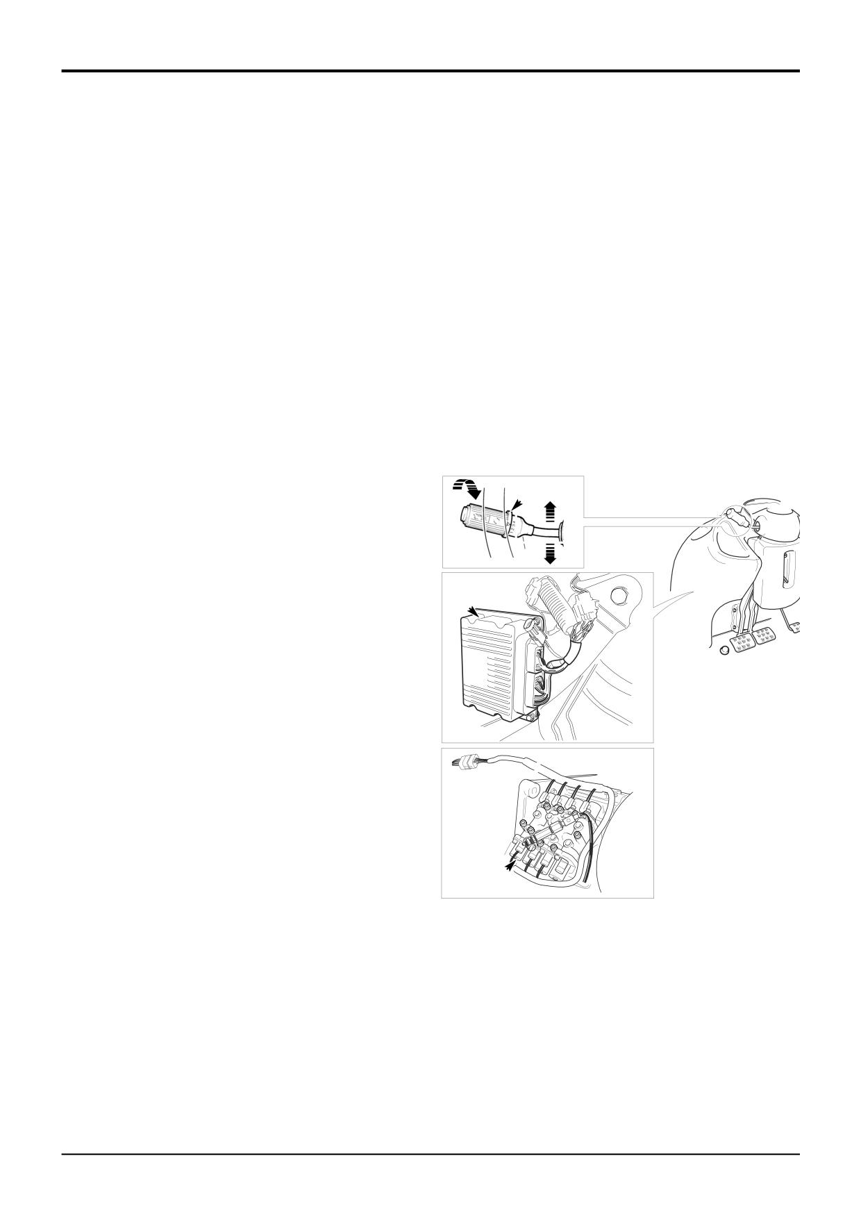
Central to the system is the ShiftMaster ECU (Electronic
Transmission dump
Control Unit) A. The unit receives ‘inputs’ from electrical
When the operator presses the dump switch the ECU selects
devices such as the gear select switch B. Depending on the
neutral by de-energising one clutch only. This enables
input signals the ECU ‘outputs’ energise electrical devices
smooth re-engagement of gears when the dump button is
such as gearbox solenoid control valves C. For a full
released.
description of how the ShiftMaster electrical system works
see Electrical Connections - Powershift Gearbox - 6
Limp modes
Speed
When necessary the ECU will provide alternative gear
selection should faults occur. This enables the machine to be
Start up
moved (‘limped’) under its own power. For full details of the
When the starter switch is set to the ON position the ECU
limp modes see Fault Finding - Powershift Gearbox.
performs a series of self checks. If the checks are valid three
beeps sound. After the checks the ECU selects neutral even
if forward or reverse is selected on the column lever. To
select forward or reverse the operator must cycle the lever
through neutral.
If the checks fail, 1 or 2 beeps will sound and the ECU will
enter an appropriate limp mode (see Limp modes)..
‘Manual’ gear select
1
B
The operator can ‘manually’ select 1st, 2nd and 3rd gears
2
F
using the column switch. When down shifting (say from 3rd
3
N
A
R
to 2nd) the ECU checks to see if the machine road speed is
suitable before down shifting the gearbox. If the road speed
is too high a repeating double beep is sounded. When the
road speed reduces to a pre-set value the ECU down shifts
the gearbox and the beeps will stop.
A
Kick down operation
A floor mounted kickdown switch enables the operator to
down shift to the next lowest gear. The ECU checks to see if
the machine road speed is suitable before down shifting the
gearbox. If the road speed is too high a single double beep
is sounded.
Pressing the kick down switch a second time causes the
ECU to select the previous gear.
‘Automatic’ gear selection
When A (auto) and F (forward) are selected on the column
switch, the ECU selects 4th, 5th or 6th gears, mainly
according to road speed. The gearbox will automatically up
shift and down shift. 2WD†† will also be selected.
To enable up shifts the accelerator pedal must be pressed,
this prevents up shifting when coasting down hill for
C
example, thus ensuring maximum machine control.
Note that the ECU does not automatically shift gears in
A405710
response to engine load.
When A (auto) and R (reverse) are selected the ECU selects
4th gear and 2WD††. There is no automatic gear shifting in
reverse.
†† On machines with 4WB (4 wheel brake), if the operator
has selected 4WB the ECU will automatically select 4WD (4
wheel drive) when the brake pedal is pressed.
Park brake ON
When the park brake is on, the ECU will hold the gearbox in
neutral even if forward or reverse are selected. A continuous
tone is sounded.
9803/3280
Issue 1
Section F
Transmission
Section F
18 - 1
Basic Operation
18 - 1
Powershift Gearbox
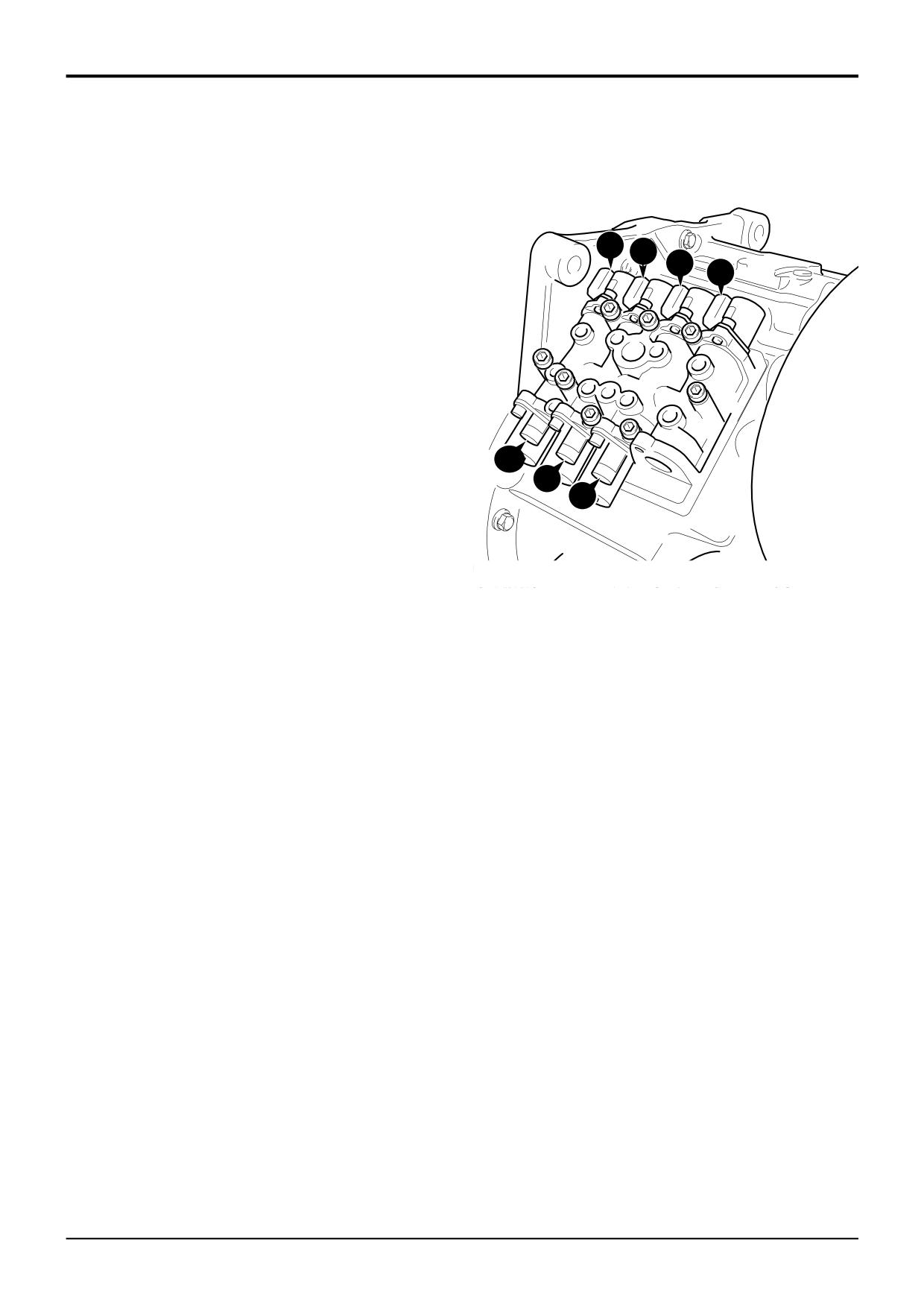
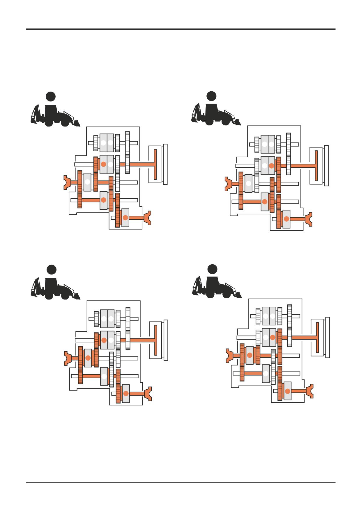
Drivepaths - 4 Speed
1F
1st GEAR FORWARD (4 wheel drive)
Clutches Engaged
Solenoids Energised
T
Forward Low
Ts
Ts Us
Ws
Z
Layshaft
Zs
Vs
S
2/4 Wheel Drive
Ss
2F
2nd GEAR FORWARD (4 wheel drive)
Clutches Engaged
Solenoids Energised
U
Forward High
Us
Z
Layshaft
Zs
S
2/4 Wheel Drive
Ss
3F
3rd GEAR FORWARD (4 wheel drive)
Ss
Clutches Engaged
Solenoids Energised
Ys
T
Forward Low
Ts
Zs
Y
Mainshaft
Ys
S
2/4 Wheel Drive
Ss
4F
A396740
4th GEAR FORWARD (4 wheel drive)
Clutches Engaged
Solenoids Energised
U
Forward High
Us
Y
Mainshaft
Ys
S
2/4 Wheel Drive
Ss
9803/3280
Issue 1
Section F
Transmission
Section F
18 - 2
Basic Operation
18 - 2
Powershift Gearbox
1F
2F
W
V
W
V
T
U
T
U
Y
Y
Z
Z
S
S
A396660
A396670
3F
4F
W
V
W
V
T
U
T
U
Y
Y
Z
Z
S
S
A396690
A396680
9803/3280
Issue 1
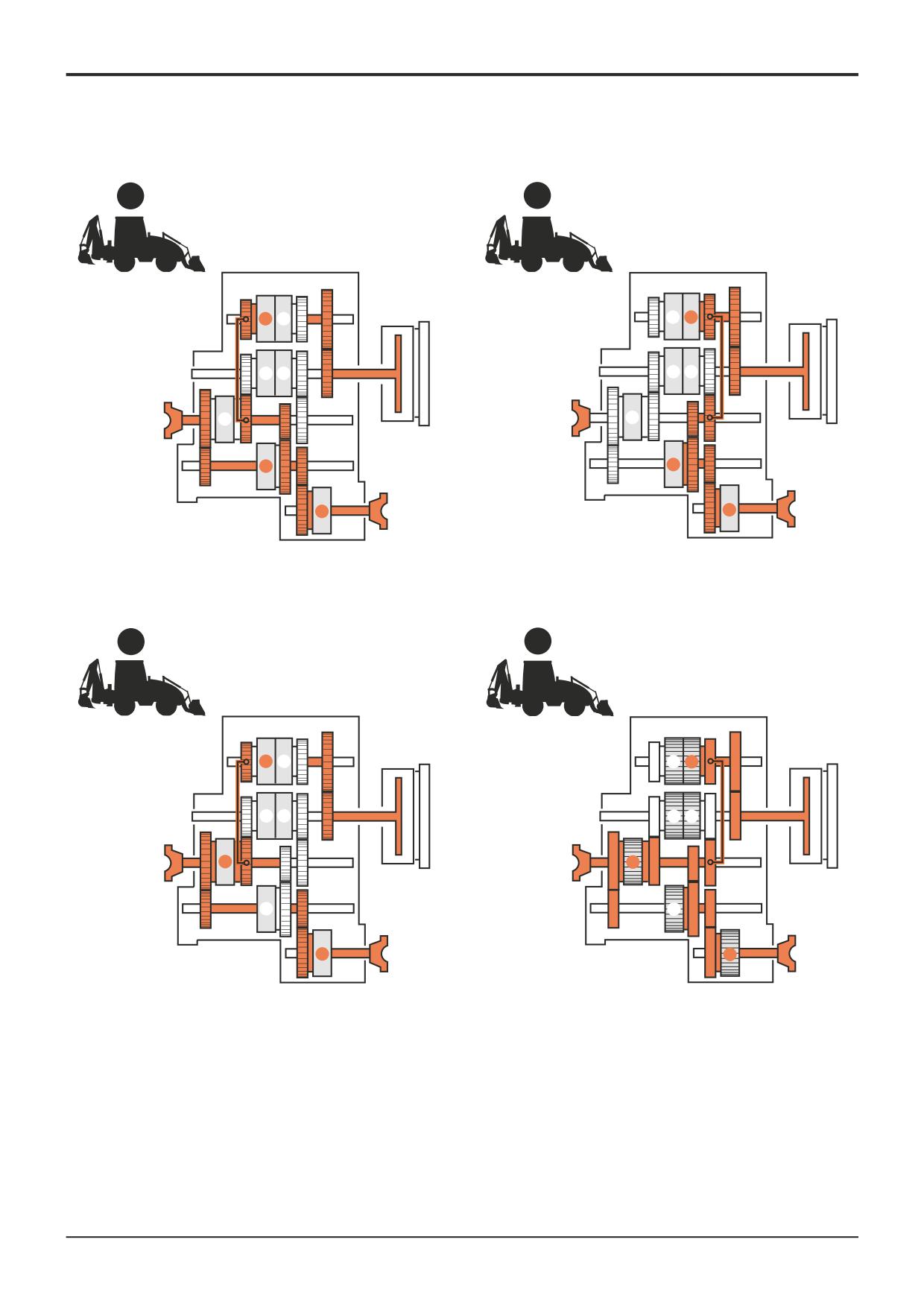
Section F
Transmission
Section F
18 - 3
Basic Operation
18 - 3
Powershift Gearbox
1R
2R
W
V
W
V
T
U
T
U
Y
Y
Z
Z
S
S
A396700
A396710
3R
4R
W
V
W
V
T
U
T
U
Y
Y
Z
Z
S
S
A396720
A396730
9803/3280
Issue 1
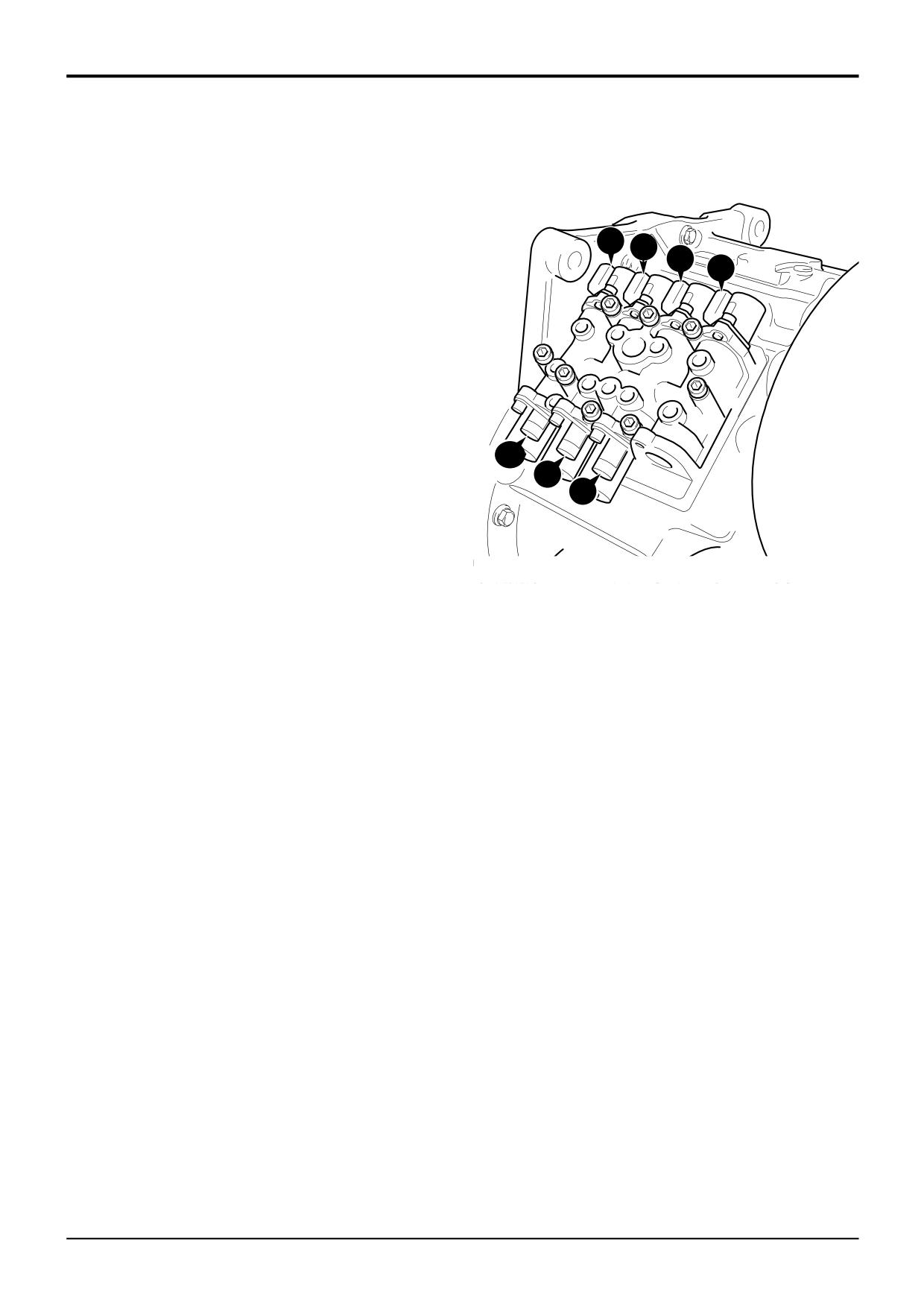
Section F
Transmission
Section F
18 - 4
Basic Operation
18 - 4
Powershift Gearbox
Drivepaths - 4 Speed
1R
1st GEAR REVERSE (4 wheel drive)
Clutches Engaged
Solenoids Energised
W
Reverse Low
Ws
Ts Us
Ws
Z
Layshaft
Zs
Vs
S
2/4 Wheel Drive
Ss
2R
2nd GEAR REVERSE (4 wheel drive)
Clutches Engaged
Solenoids Energised
V
Reverse High
Vs
Z
Layshaft
Zs
S
2/4 Wheel Drive
Ss
3R
Ss
3rd GEAR REVERSE (4 wheel drive)
Clutches Engaged
Solenoids Energised
Ys
W
Reverse Low
Ws
Zs
Y
Mainshaft
Ys
S
2/4 Wheel Drive
Ss
A396740
4R
4th GEAR REVERSE (4 wheel drive)
Clutches Engaged
Solenoids Energised
V
Reverse High
Vs
Y
Mainshaft
Ys
S
2/4 Wheel Drive
Ss
9803/3280
Issue 1
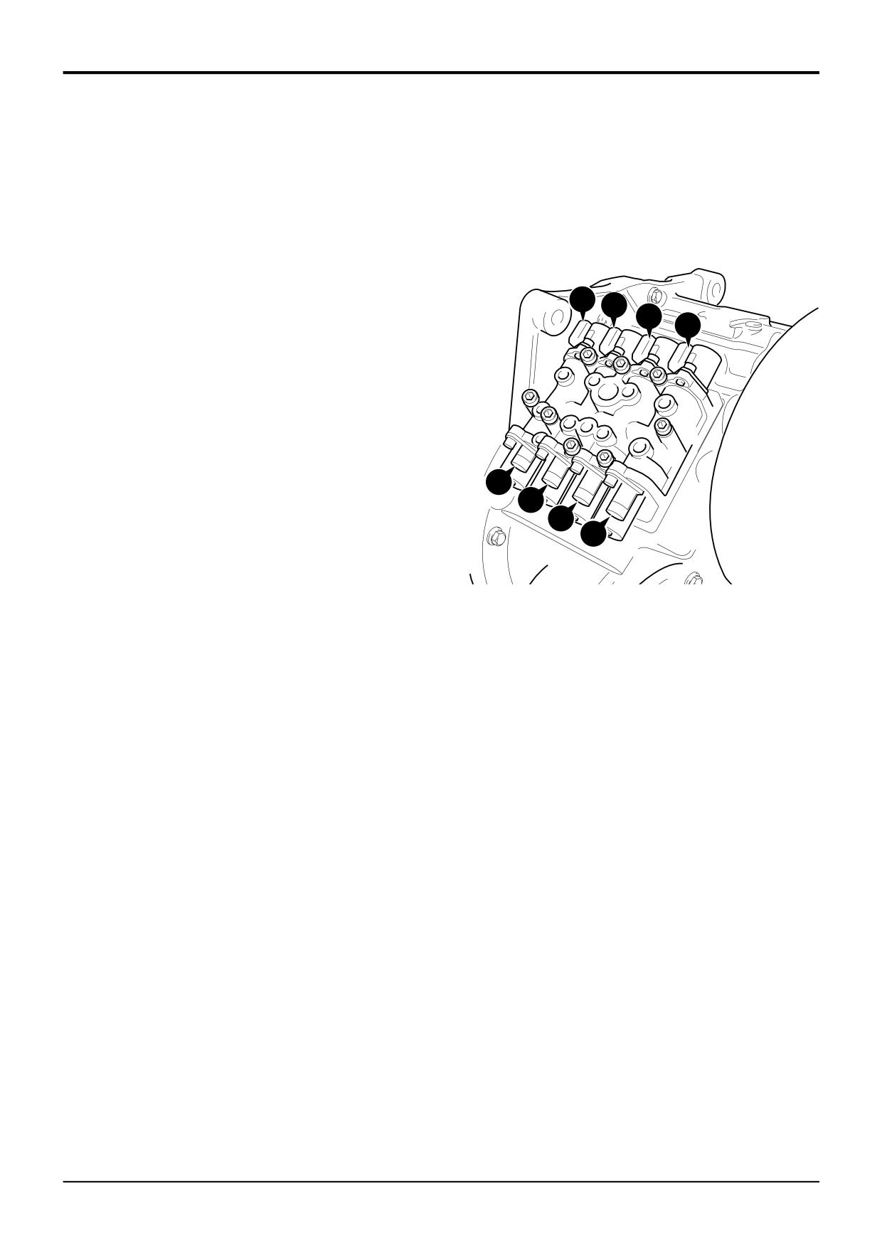
Section F
Transmission
Section F
18 - 5
Basic Operation
18 - 5
Powershift Gearbox
Drivepaths - 6 Speed
1F
1st GEAR FORWARD (4 wheel drive)
Clutches Engaged
Solenoids Energised
X
‘6 Speed’
Xs
Z
Layshaft
Zs
S
2/4 Wheel Drive
Ss
2F
Ts Us
Ws
2nd GEAR FORWARD (4 wheel drive)
Vs
Clutches Engaged
Solenoids Energised
T
Forward Low
Ts
Z
Layshaft
Zs
S
2/4 Wheel Drive
Ss
3F
3rd GEAR FORWARD (4 wheel drive)
Clutches Engaged
Solenoids Energised
U
Forward High
Us
Ss
Z
Layshaft
Zs
Ys
S
2/4 Wheel Drive
Ss
Zs
Xs
4F
4th GEAR FORWARD (4 wheel drive)
Clutches Engaged
Solenoids Energised
X
‘6 Speed’
Xs
Y
Mainshaft
Ys
S
2/4 Wheel Drive
Ss
5F
5th GEAR FORWARD (4 wheel drive)
Clutches Engaged
Solenoids Energised
T
Forward Low
Ts
Y
Mainshaft
Ys
S
2/4 Wheel Drive
Ss
6F
6th GEAR FORWARD (4 wheel drive)
Clutches Engaged
Solenoids Energised
U
Forward High
Us
Y
Mainshaft
Ys
S
2/4 Wheel Drive
Ss
9803/3280
Issue 1
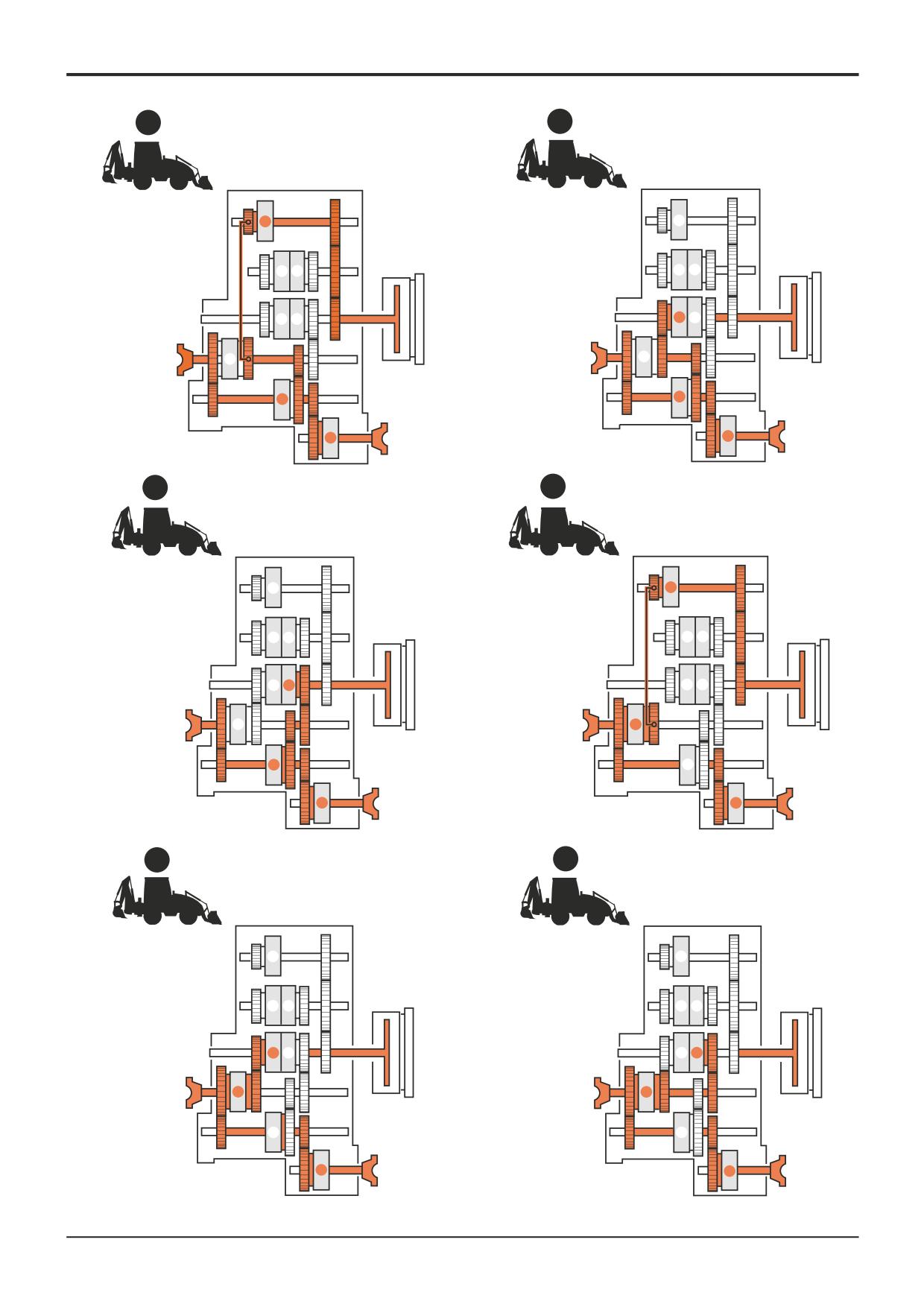
Section F
Transmission
Section F
18 - 6
Basic Operation
18 - 6
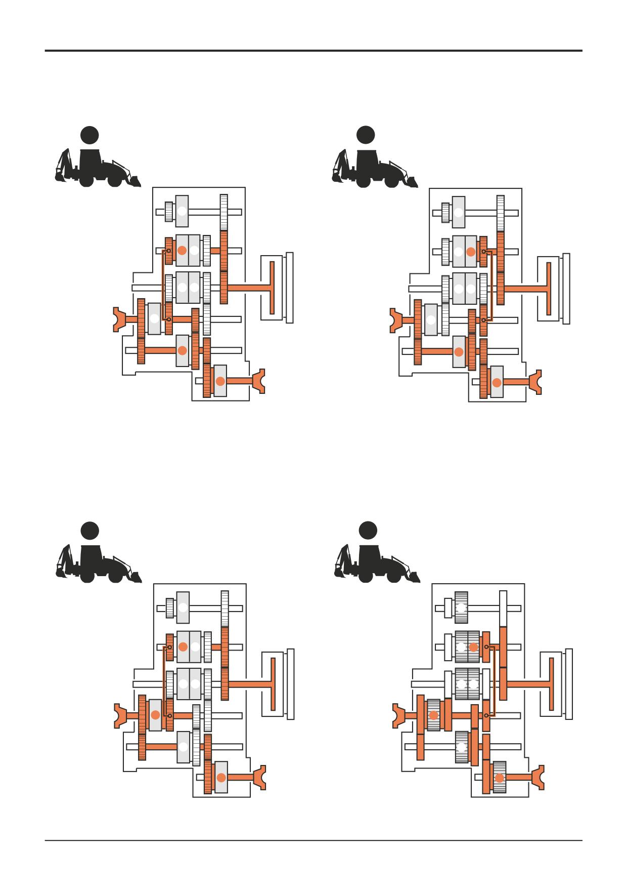
1F
2F
X
X
W
V
W
V
T
U
T
U
Y
Y
Z
Z
S
S
3F
A387850
4F
A387860
X
X
W
V
W
V
T
U
T
U
Y
Y
Z
Z
S
S
A387870
A387880
5F
6F
X
X
W
V
W
V
T
U
T
U
Y
Y
Z
Z
S
S
A387890
A387900
9803/3280
Issue 1
Section F
Transmission
Section F
18 - 7
Basic Operation
18 - 7
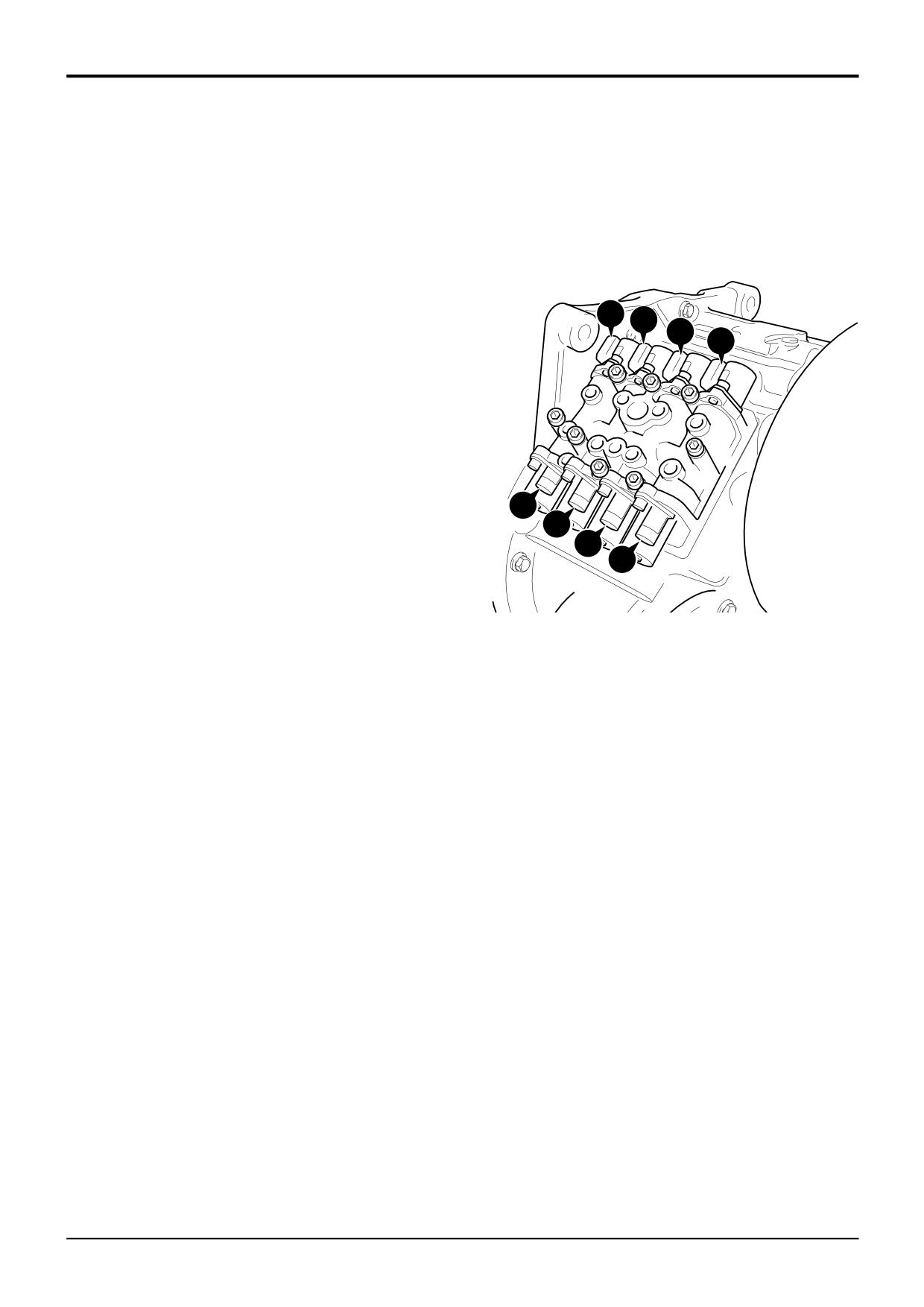
1R
2R
X
X
W
V
W
V
T
U
T
U
Y
Y
Z
Z
S
S
A387910
A387920
3R
4R
X
X
W
V
W
V
T
U
T
U
Y
Y
Z
Z
S
S
A387930
A387940
9803/3280
Issue 1
Section F
Transmission
Section F
18 - 8
Basic Operation
18 - 8
Powershift Gearbox
Drivepaths - 6 Speed
1R
1st GEAR REVERSE (4 wheel drive)
Clutches Engaged
Solenoids Energised
W
Reverse Low
Ws
Z
Layshaft
Zs
S
2/4 Wheel Drive
Ss
2R
Ts Us
2nd GEAR REVERSE (4 wheel drive)
Ws
Vs
Clutches Engaged
Solenoids Energised
V
Reverse High
Vs
Z
Layshaft
Zs
S
2/4 Wheel Drive
Ss
3R
3rd GEAR REVERSE (4 wheel drive)
Clutches Engaged
Solenoids Energised
W
Reverse Low
Ws
Y
Mainshaft
Ys
Ss
S
2/4 Wheel Drive
Ss
Ys
Zs
4R
Xs
4th GEAR REVERSE (4 wheel drive)
Clutches Engaged
Solenoids Energised
V
Reverse High
Vs
Y
Mainshaft
Ys
S
2/4 Wheel Drive
Ss
9803/3280
Issue 1