JCB 3CX, 4CX, 214e, 214, 215, 217 & VARIANTS Backhoe Loader. Service Manual - page 20
Section E
Hydraulics
Section E
70 - 3
Hose Burst Protection Valves
70 - 3
Dismantling and Assembly (Cont’d)
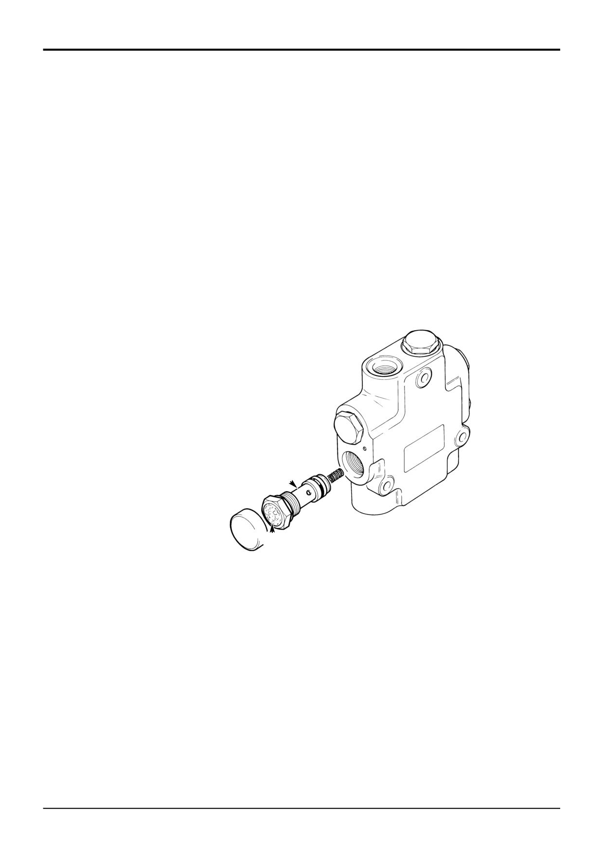
- Boom and Dipper Rams
This procedure applies to Hose Burst Protection Valves
fitted to the boom/dipper rams ONLY.
There is no servicing permitted on this valve apart from the
removing and fitting a new check valve assembly A when
the seal B has been broken.
DO NOT use the machine with a broken seal.
If the assembly is fitted to the machine, before removing the
check valve A, operate the main service control levers back
and forth to vent residual pressure.
After fitting a new check valve ensure that the valve
assembly operates correctly, refer to Service Procedures,
Hose Burst Protection Valves - Checking.
A
S327320
B
9803/3280
Issue 1
Section E
Section E
Hydraulics
75 - 1
Hydraulic Rams
75 - 1
Removal and Replacement
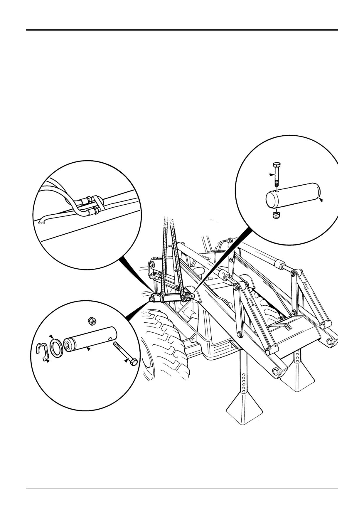
- Loader Lift Ram
B
A
C
F
G
E
D
S266330
9803/3280
Issue 1
www.WorkshopManuals.co.ukSection E
Section E
Hydraulics
75 - 2
Hydraulic Rams
75 - 2
Removal and Replacement
- Loader Lift Ram
Removal
Replacement
! WARNING
Replacement is a reversal of the removal sequence.
The loader arm interlevers are potentially dangerous,
when pivoting about their centre they form a 'scissor'
point with the loader arm. Make sure the interlevers are
! WARNING
securely blocked when working in the loader arm area.
Fine jets of hydraulic fluid at high pressure can
BF 2-1
penetrate the skin. Do not use your fingers to check for
hydraulic fluid leaks. Do not put your face close to
1
Park the machine on firm level ground. Engage the
suspected leaks. Hold a piece of cardboard close to
parking brake and set the transmission to neutral.
suspected leaks and then inspect the cardboard for
signs of hydraulic fluid. If hydraulic fluid penetrates your
2
Raise the loader arms to give access to the lift ram pivot
skin, get medical help immediately.
pins C. The loader arms must be supported, use a tool
INT-3-1-10/1
as shown.
Coat pivot pins with anti-rust lubricant.
! DANGER
Hydraulic Pressure
Make sure that the head of item D is on the engine side.
Hydraulic fluid at system pressure can injure you. Before
disconnecting or connecting hydraulic hoses, stop the
Coat mainframe bores with grease.
engine and operate the controls to release pressure
trapped in the hoses. Make sure the engine cannot be
Assembly sequence for shim F and klipring:
started while the hoses are open.
INT-3-1-11/1
1st shim
2nd ram
3
Switch off the engine and vent residual hydraulic
3rd shim (as required)
pressure from the loader end by operating the loader
4th klipring
controls back and forth several times.
Pivot pins with M24 pin extractor hole
Note: If a hose burst protection valve is fitted on the ram, the
1st spacer
system will not vent. Extreme caution must be used when
2nd ram
releasing hydraulic connections - release the connections
3rd shim (as required)
one turn and allow the pressure to dissipate.
4th klipring
4
Label and then remove the lift ram hoses A. Plug and
All klipring installations to have a maximum end float of
cap all open orifices to prevent loss of fluid and ingress
2mm (0.080in.)
of dirt.
! CAUTION
This component is heavy. Do not attempt to remove it
unless its weight is held by a sling. Make sure that the
sling is attached to a suitable lifting appliance.
HYD 2-3/1
5
Fasten lifting straps to the lift ram, make sure that the
weight of the ram is supported by the sling.
6
Remove pivot pin retaining bolt B and then remove the
pivot pin C.
7
Remove pivot pin retaining bolt D.
8
Remove klipring E and shim F from both sides of ram,
use slide hammer kit (service tool 993/68100) to remove
pivot pin G.
9
Remove the lift ram.
9803/3280
Issue 1
Section E
Section E
Hydraulics
76 - 1
Hydraulic Rams
76 - 1
Removal and Replacement
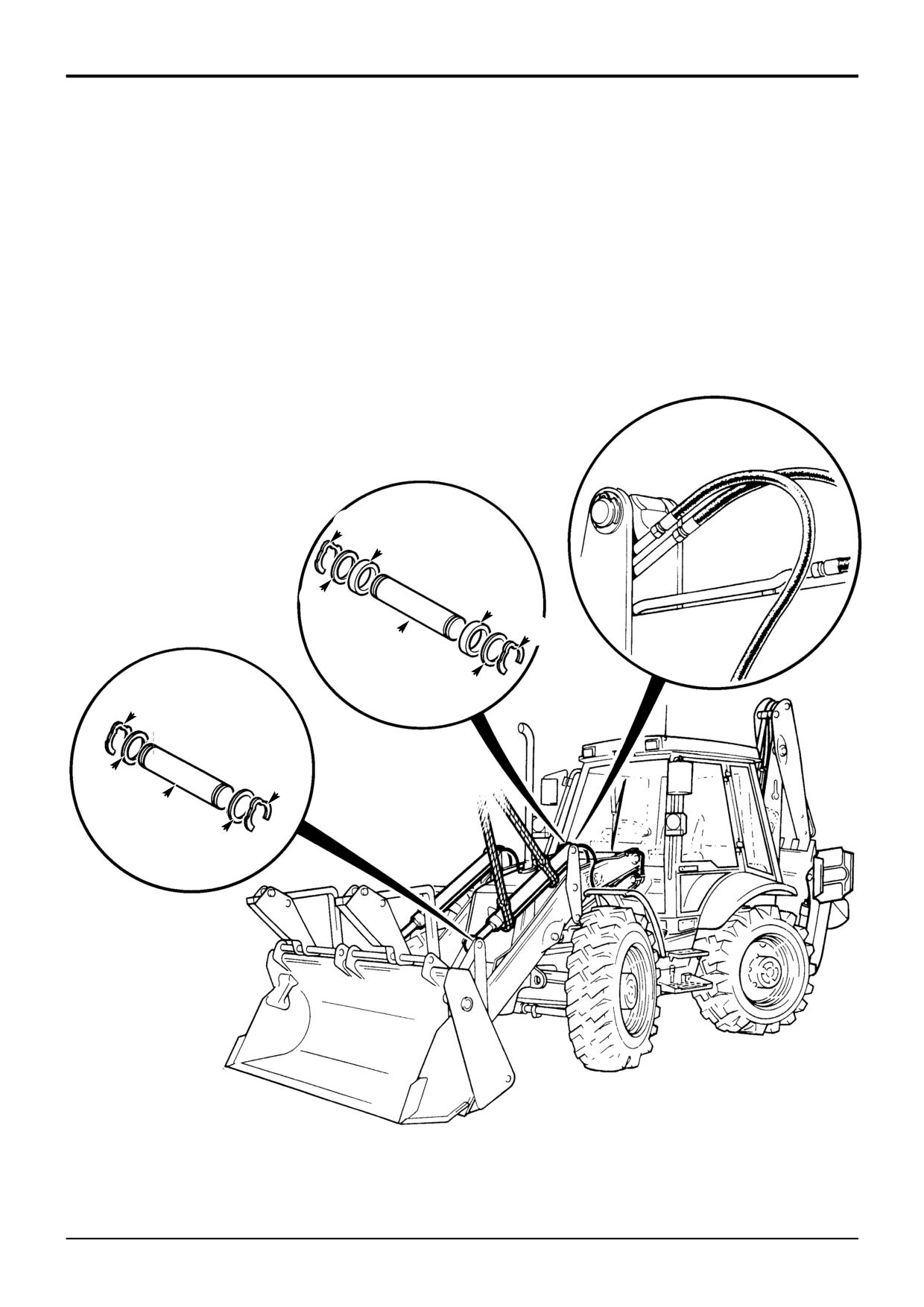
- Loader Shovel Ram
A
B
D
C
D
B
E
C
B
C
B
E
C
S266340
9803/3280
Issue 1
www.WorkshopManuals.co.ukSection E
Section E
Hydraulics
76 - 2
Hydraulic Rams
76 - 2
Removal and Replacement
- Loader Shovel Ram
Removal
Replacement
! WARNING
Replacement is a reversal of the removal sequence.
The loader arm interlevers are potentially dangerous,
when pivoting about their centre they form a 'scissor'
point with the loader arm. Make sure the interlevers are
! WARNING
securely blocked when working in the loader arm area.
Fine jets of hydraulic fluid at high pressure can
BF 2-1
penetrate the skin. Do not use your fingers to check for
hydraulic fluid leaks. Do not put your face close to
1
Park the machine on firm level ground. Engage the
suspected leaks. Hold a piece of cardboard close to
parking brake and set the transmission to neutral.
suspected leaks and then inspect the cardboard for
signs of hydraulic fluid. If hydraulic fluid penetrates your
2
Rest the shovel flat on the ground.
skin, get medical help immediately.
INT-3-1-10/1
DANGER
Coat pivot pins with anti-rust lubricant.
Hydraulic Pressure
Hydraulic fluid at system pressure can injure you. Before
All klipring intallations to have a maximum end float of 2mm
disconnecting or connecting hydraulic hoses, stop the
(0.080in.)
engine and operate the controls to release pressure
trapped in the hoses. Make sure the engine cannot be
Make sure that each klipring is installed with a shim.
started while the hoses are open.
INT-3-1-11/1
3
Switch off the engine and vent residual hydraulic
pressure from the loader end by operating the loader
controls back and forth several times.
4
Label and then remove the shovel ram hoses A. Plug
and cap all open orifices to prevent loss of fluid and
ingress of dirt.
! CAUTION
This component is heavy. Do not attempt to remove it
unless its weight is held by a sling. Make sure that the
sling is attached to a suitable lifting appliance.
HYD 2-3/1
5
Fasten lifting straps to the shovel ram, make sure that
the weight of the ram is supported by the sling.
6
Remove kliprings B, shims C and spacers D.
7
Remove pivot pins E.
9803/3280
Issue 1
Section E
Section E
Hydraulics
77 - 1
Hydraulic Rams
77 - 1
Removal and Replacement
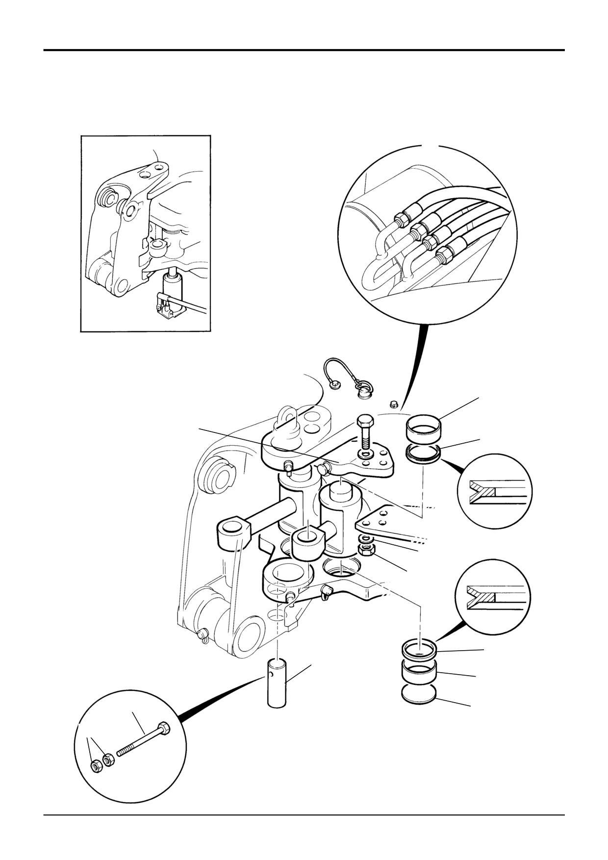
- Slew Ram
1
Y
7
3
10
2A
2
10
6
8
5
9
4
S254901
9803/3280
Issue 1
Section E
Section E
Hydraulics
77 - 2
Hydraulic Rams
77 - 2
Removal and Replacement
- Slew Ram
Removal
Inspection
1
Slew the backhoe to the left to remove the right hand
Inspect the liner bearings 7 (located in the trunnion retaining
slew ram and visa versa.
bracket 3) and liner bearing 8 for signs of damage, wear,
scores or nicks etc. Replace as required.
2
Lower the bucket to the ground and switch off the
engine.
To remove the liner bearing 8 use a jack located against
blanking plate 9. Shown in the inset at Y.
! WARNING
Hydraulic fluid at system pressure can injure you. Before
To remove the bearing liner 7 from the trunnion bracket use
disconnecting or connecting hydraulic hoses, stop the
flat faced bearing pullers.
engine and operate the controls to release pressure
trapped in the hoses. Make sure the engine cannot be
started while the hoses are open.
Replacement
INT-3-1-11/1
! WARNING
3
Vent any residual hydraulic pressure by operating the
Fine jets of hydraulic fluid at high pressure can
backhoe and slew control levers.
penetrate the skin. Do not use your fingers to check for
hydraulic fluid leaks. Do not put your face close to
4
Disconnect the hydraulic hoses 1 to the slew rams -
suspected leaks. Hold a piece of cardboard close to
before disconnecting the hoses make sure that they are
suspected leaks and then inspect the cardboard for
labelled (to assist with reassembly).
signs of hydraulic fluid. If hydraulic fluid penetrates your
skin, get medical help immediately.
5
Plug and cap all open hydraulic connections to prevent
INT-3-1-10/1
ingress of dirt and loss of hydraulic fluid.
Replacement is generally a reversal of the removal
6
Loosen and remove trunnion bracket retaining nuts 2
procedures, however note the following:
and hardened washers 2A (see note).
The liner bearings 7 and 8 have a ‘lead-in’ diameter
Note: On assembly, the correct grade of nut (grade 12) and
(noticeable with a slight step), always install the smaller
bolt (grade 10.9) must be used. Also, use hardened washers
diameter first into the pivot bore. The bearings must be
2A - NOT ordinary washers. Using incorrect specification
installed so that they sit flush.
items could result in a reduction of clamping efficiency.
The eye end pivot pins 6 should be secured first - i.e.
7
Remove the trunnion bracket 3.
BEFORE the trunnion bracket retaining nuts 2, this will help
to maximise ram assembly alignment.
! CAUTION
This component is heavy. Do not attempt to remove it
Make sure that the hydraulic hoses are correctly installed.
unless its weight is held by a sling. Make sure that the
sling is attached to a suitable lifting appliance.
Make sure that any new or reused bearings are clean and
HYD 2-3/1
smeared with grease prior to reassembly of pins and
trunnion journals.
8
Attach suitable lifting straps to the slew ram assembly.
Note that the weight of the slew ram assembly is
When fully assembled, apply grease at each grease nipple
approximately 44 kg (97 lbs).
BEFORE operating the machine.
9
Remove thin nuts 4 ( 2 off per pivot pin) and remove the
Torque Setting
pivot pin retaining bolt 5. Use a 25 - 30 mm diameter
Item
Nm
lb ft
kgf m
bar to knock the pin out vertically.
2
650
480
66.3
10
Remove the slew ram (eye end) pivot pin 6 and swing
the ram to clear the kingpost casting.
11
Lift the slew ram assembly clear of the machine.
9803/3280
Issue 1
Section E
Section E
Hydraulics
78 - 1
Hydraulic Rams
78 - 1
H
E
G
L
F
E
L
G
C
A
B
D
S271860
9803/3280
Issue 1
www.WorkshopManuals.co.ukSection E
Section E
Hydraulics
78 - 2
Hydraulic Rams
78 - 2
Removal and Replacement
- Stabiliser Ram (Sideshift)
Removal
Replacement
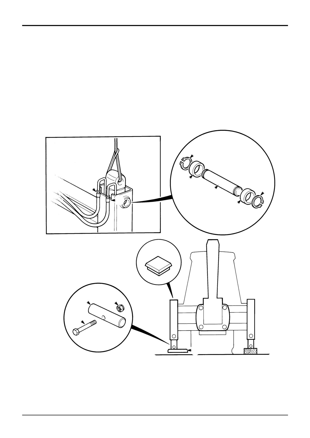
1
Park the machine on firm level ground, engage the
Replacement is a reversal of the removal sequence.
parking brake and set the transmission to neutral.
Lower the backhoe and loader end to the ground.
! WARNING
Fine jets of hydraulic fluid at high pressure can
2
Lower the stabiliser legs until the pads are
penetrate the skin. Do not use your fingers to check for
approximately 4 in. (100mm) off the ground and stop
hydraulic fluid leaks. Do not put your face close to
the engine.
suspected leaks. Hold a piece of cardboard close to
suspected leaks and then inspect the cardboard for
3
Remove the bottom locking nut A and bolt B. Drive out
signs of hydraulic fluid. If hydraulic fluid penetrates your
the bottom pivot pin C and allow the stabiliser foot D to
skin, get medical help immediately.
fall clear. Lift the inner leg and temporarily refit the pivot
INT-3-1-10/1
pin C through inner leg and ram.
4
Place a block of wood underneath the stabiliser leg.
Use suitable lifting appliances to locate the stabiliser ram.
5
Remove circlips E and drive out top pivot pin F with
After replacing or fitting the ram, connect the hydraulic
spacing collars G.
pipes, make sure that the ram and leg operate freely and do
not foul.
6
Start the engine and slowly extend the stabiliser ram so
that the dump end of the ram protrudes from the top of
the outer leg section.
7
Attach suitable lifting gear to the ram as shown at H.
Make sure that the weight of the ram is supported by
the sling and remove the bottom pivot pin C.
DANGER
Hydraulic Pressure
Hydraulic fluid at system pressure can injure you. Before
disconnecting or connecting hydraulic hoses, stop the
engine and operate the controls to release pressure
trapped in the hoses. Make sure the engine cannot be
started while the hoses are open.
INT-3-1-11/1
8
Make sure the engine is switched off, vent residual
hydraulic pressure by moving the backhoe and
stabiliser control levers back and forth.
Note: If a check valve is fitted on the ram, the system will not
vent. Extreme caution must be used when releasing
hydraulic connections - release the connections one turn and
allow the pressure to dissipate.
9
Loosen and remove the stabiliser hoses L, label the
hoses before removing (as an aid to assembly). Plug all
open orifices to prevent loss of fluid and ingress of dirt.
! CAUTION
This component is heavy. Do not attempt to remove it
unless its weight is held by a sling. Make sure that the
sling is attached to a suitable lifting appliance.
HYD 2-3/1
10
Using suitable lifting equipment, lift the ram clear.
9803/3280
Issue 1
www.WorkshopManuals.co.ukSection E
Section E
Hydraulics
78 - 3
Hydraulic Rams
78 - 3
Removal and Replacement
- Stabiliser Ram (Centremount)
Removal
Replacement
1
Park the machine on firm level ground, engage the
Replacement is a reversal of the removal sequence.
parking brake and set the transmission to neutral.
Lower the stabiliser legs to the ground.
! WARNING
Fine jets of hydraulic fluid at high pressure can
2
Lower the backhoe and loader end to the ground and
penetrate the skin. Do not use your fingers to check for
stop the engine.
hydraulic fluid leaks. Do not put your face close to
suspected leaks. Hold a piece of cardboard close to
suspected leaks and then inspect the cardboard for
DANGER
signs of hydraulic fluid. If hydraulic fluid penetrates your
Hydraulic Pressure
skin, get medical help immediately.
Hydraulic fluid at system pressure can injure you. Before
INT-3-1-10/1
disconnecting or connecting hydraulic hoses, stop the
engine and operate the controls to release pressure
Use suitable lifting appliances to locate the stabiliser ram.
trapped in the hoses. Make sure the engine cannot be
started while the hoses are open.
INT-3-1-11/1
After replacing or fitting the ram, connect the hydraulic
pipes, make sure that the ram and leg operate freely and do
not foul.
3
Make sure the engine is switched off, vent residual
hydraulic pressure by moving the backhoe and
stabiliser control levers back and forth.
Note: If a check valve is fitted on the ram, the system will not
vent. Extreme caution must be used when releasing
C
hydraulic connections - release the connections one turn and
allow the pressure to dissipate.
4
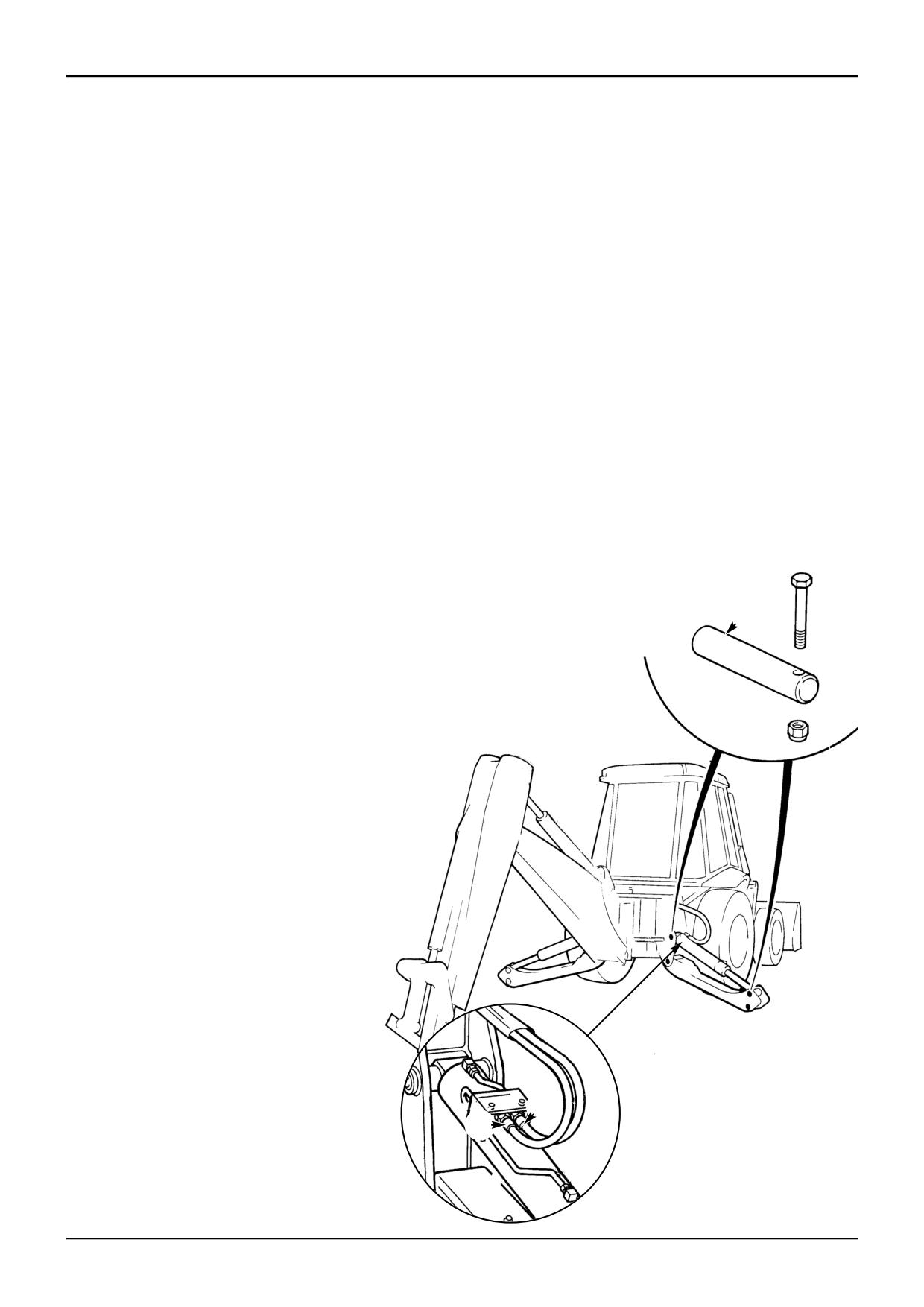
Carefully disconnect hydraulic hoses A and B from the
stabiliser hydraulic ram, label the hoses before
removing (as an aid to assembly). Release the
connections slowly.
! CAUTION
This component is heavy. Do not attempt to remove it
unless its weight is held by a sling. Make sure that the
sling is attached to a suitable lifting appliance.
HYD 2-3/1
5
Wrap a suitable sling around the stabiliser ram, make
sure that the weight of the ram is supported by the
sling.
6
Remove the ram pivot pin retaining nut and
bolt, drive out the ram pivot pin as shown at
C.
7
Remove the stabiliser ram.
S263080
B
A
S261790
9803/3280
Issue 1
Section E
Section E
Hydraulics
79 - 1
Hydraulic Rams
79 - 1
Removal and Replacement
- Dipper Ram
A
C
B
D
D
B
C
S266350
9803/3280
Issue 1
www.WorkshopManuals.co.ukSection E
Section E
Hydraulics
79 - 2
Hydraulic Rams
79 - 2
Removal and Replacement
- Dipper Ram
Removal
Replacement
1
Park the machine on firm level ground, engage the
Replacement is a reversal of the removal sequence.
parking brake and set the transmission to neutral.
Lower the backhoe and loader end to the ground and
! WARNING
stop the engine.
Fine jets of hydraulic fluid at high pressure can
penetrate the skin. Do not use your fingers to check for
DANGER
hydraulic fluid leaks. Do not put your face close to
Hydraulic Pressure
suspected leaks. Hold a piece of cardboard close to
Hydraulic fluid at system pressure can injure you. Before
suspected leaks and then inspect the cardboard for
disconnecting or connecting hydraulic hoses, stop the
signs of hydraulic fluid. If hydraulic fluid penetrates your
engine and operate the controls to release pressure
skin, get medical help immediately.
INT-3-1-10/1
trapped in the hoses. Make sure the engine cannot be
started while the hoses are open.
INT-3-1-11/1
2
Vent residual hydraulic pressure from the backhoe
hoses by operating the backhoe controls back and forth
several times.
Note: If a hose burst protection valve is fitted on the ram, the
system will not vent. Extreme caution must be used when
releasing hydraulic connections - release the connections
one turn and allow the pressure to dissipate.
3
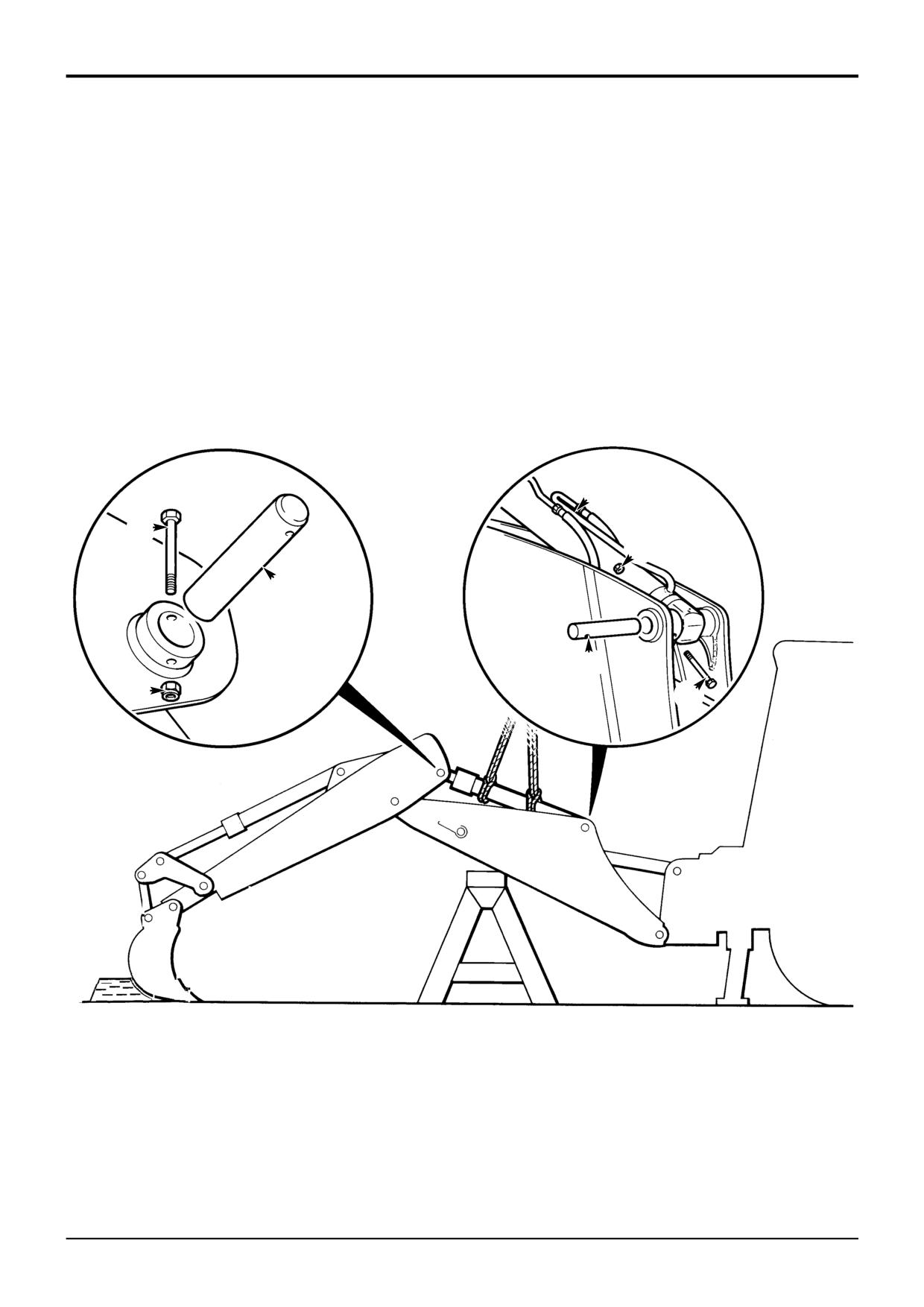
Label and then remove the dipper ram hoses A. Plug
and cap all open orifices to prevent loss of fluid and
ingress of dirt.
! CAUTION
This component is heavy. Do not attempt to remove it
unless its weight is held by a sling. Make sure that the
sling is attached to a suitable lifting appliance.
HYD 2-3/1
4
Fasten lifting straps to the dipper ram, make sure that
the weight of the ram is supported by the sling.
5
Remove the pivot pin retaining nut B and bolt C,
remove the pivot pin D.
6
Remove dipper ram.
9803/3280
Issue 1
Section E
Section E
Hydraulics
80 - 1
Hydraulic Rams
80 - 1
Removal and Replacement
- Bucket Crowd Ram
B
C
A
D
D
B
C
S266360
9803/3280
Issue 1
www.WorkshopManuals.co.ukSection E
Section E
Hydraulics
80 - 2
Hydraulic Rams
80 - 2
Removal and Replacement
- Bucket Crowd Ram
Removal
Replacement
1
Park the machine on firm level ground, engage the
Replacement is a reversal of the removal sequence.
parking brake and set the transmission to neutral.
Lower the backhoe and loader end to the ground and
! WARNING
stop the engine.
Fine jets of hydraulic fluid at high pressure can
penetrate the skin. Do not use your fingers to check for
DANGER
hydraulic fluid leaks. Do not put your face close to
Hydraulic Pressure
suspected leaks. Hold a piece of cardboard close to
Hydraulic fluid at system pressure can injure you. Before
suspected leaks and then inspect the cardboard for
disconnecting or connecting hydraulic hoses, stop the
signs of hydraulic fluid. If hydraulic fluid penetrates your
engine and operate the controls to release pressure
skin, get medical help immediately.
INT-3-1-10/1
trapped in the hoses. Make sure the engine cannot be
started while the hoses are open.
INT-3-1-11/1
2
Vent residual hydraulic pressure from the backhoe
hoses by operating the backhoe controls back and forth
several times.
Note: If a hose burst protection valve is fitted on the ram, the
system will not vent. Extreme caution must be used when
releasing hydraulic connections - release the connections
one turn and allow the pressure to dissipate.
3
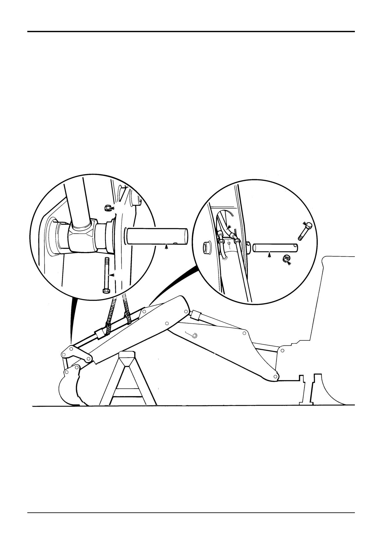
Label and then remove the bucket crowd ram hoses A.
Plug and cap all open orifices to prevent loss of fluid
and ingress of dirt.
! CAUTION
This component is heavy. Do not attempt to remove it
unless its weight is held by a sling. Make sure that the
sling is attached to a suitable lifting appliance.
HYD 2-3/1
4
Fasten lifting straps to the bucket crowd ram, make
sure that the weight of the ram is supported by the
sling.
5
Remove the pivot pin retaining nut B and bolt C,
remove the pivot pin D.
6
Remove the bucket crowd ram.
9803/3280
Issue 1
Section E
Section E
Hydraulics
81 - 1
Hydraulic Rams
81 - 1
Removal and Replacement
- Boom Ram
E
B
C
G
A
F
H
D
S266370
9803/3280
Issue 1
www.WorkshopManuals.co.ukSection E
Section E
Hydraulics
81 - 2
Hydraulic Rams
81 - 2
Removal and Replacement
- Boom Ram
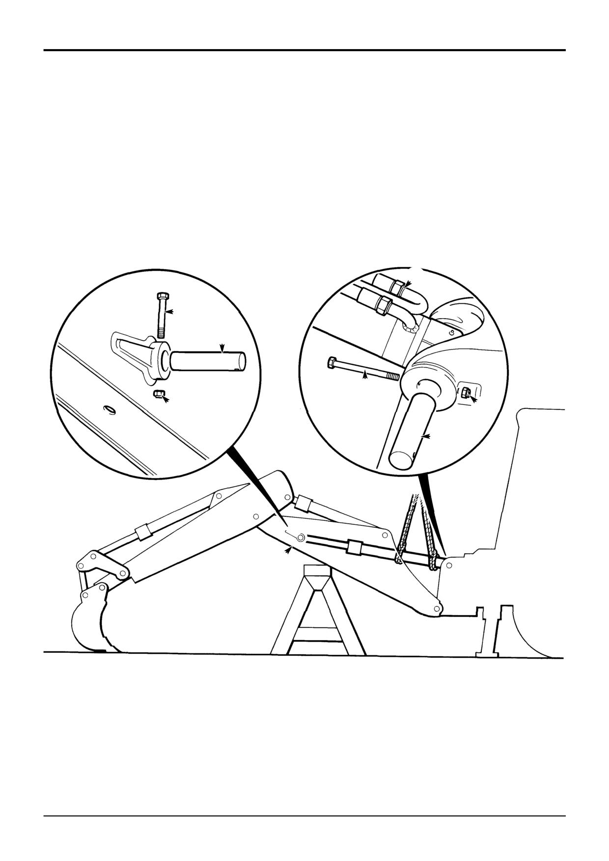
Removal
Replacement
1
Park the machine on firm level ground, engage the
Replacement is a reversal of the removal sequence.
parking brake and set the transmission to neutral.
Lower the backhoe and loader end to the ground and
! WARNING
stop the engine.
Fine jets of hydraulic fluid at high pressure can
2
Remove pivot pin retaining nut A and bolt B. Remove
penetrate the skin. Do not use your fingers to check for
hydraulic fluid leaks. Do not put your face close to
the pivot pin C.
suspected leaks. Hold a piece of cardboard close to
suspected leaks and then inspect the cardboard for
3
Remove the grease nipple from the eye end of the ram
signs of hydraulic fluid. If hydraulic fluid penetrates your
(through access hole D).
skin, get medical help immediately.
INT-3-1-10/1
4
Use the machine hydraulics to SLOWLY retract the ram.
5
Remove the hose clamp.
It will be necessary to extend the ram to align and engage
the boom pivot pin C. As the ram extends, the ram will tend
to turn.
DANGER
Hydraulic Pressure
For this reason it is recommended that a smaller diameter
Hydraulic fluid at system pressure can injure you. Before
steel bar is used to locate the boom ram at the kingpost
disconnecting or connecting hydraulic hoses, stop the
casting. The steel bar can be more readily removed to allow
engine and operate the controls to release pressure
for re-alignment of the boom pivot pin C.
trapped in the hoses. Make sure the engine cannot be
started while the hoses are open.
When the boom pivot pin has been correctly aligned and
INT-3-1-11/1
fitted, then fit the correct pivot pin H at the kingpost.
6
Vent residual hydraulic pressure from the backhoe
hoses by operating the backhoe controls back and forth
several times.
Note: If a hose burst protection valve is fitted on the ram, the
system will not vent. Extreme caution must be used when
releasing hydraulic connections - release the connections
one turn and allow the pressure to dissipate.
7
Label and then remove the boom ram hoses E. Plug
and cap all open orifices to prevent loss of fluid and
ingress of dirt.
! CAUTION
This component is heavy. Do not attempt to remove it
unless its weight is held by a sling. Make sure that the
sling is attached to a suitable lifting appliance.
HYD 2-3/1
8
Fasten lifting straps to the boom ram, make sure that
the weight of the ram is supported by the sling.
9
Remove the pivot pin retaining nut F and bolt G remove
the kingpost pivot pin H.
10
Remove the boom ram.
9803/3280
Issue 1
www.WorkshopManuals.co.ukSection E
Section E
Hydraulics
85 - 1
Hydraulic Rams
85 - 1
20
14
15
16
10
13
11
1
9
3
4
4
5
8
7
18
19
17
6
12
s263650
2
5
4
6
9
3
11
7
1
10
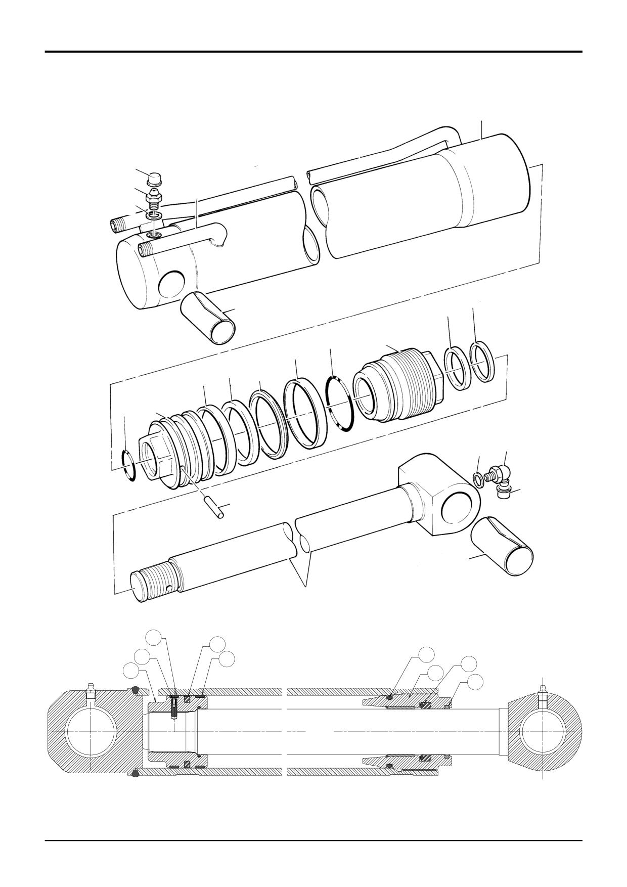
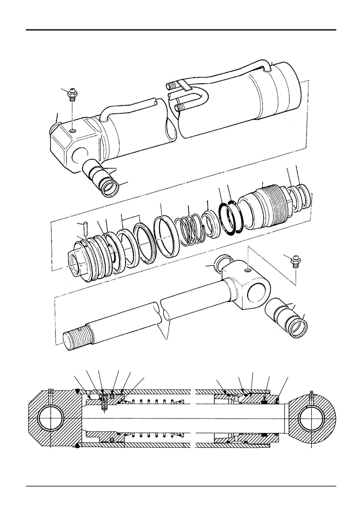
TYPICAL RAM ASSEMBLY
Note that on boom and bucket rams, pivot pin grease seals are fitted.
A263680
9803/3280
Issue 1
www.WorkshopManuals.co.ukSection E
Section E
Hydraulics
85 - 2
Hydraulic Rams
85 - 2
Dismantling and Assembly
Assembly
- Loader Lift Ram
Clean threads of piston rod, piston head, end cap and
- Loader Shovel Ram
cylinder using a wire brush. Use JCB Cleaner/Degreaser to
- Boom Ram
ensure that all threads are free from grease, hydraulic oil and
sealant. Allow 15 minutes for solvent to dry before applying
- Bucket Ram
JCB Threadlocker and Sealer (High Strength).
- Stabiliser Ram
Ensure that lubricants used during assembly do not come
Dismantling
into contact with the JCB Threadlocker and Sealer (High
The numerical sequence shown on the illustration is intended
Strength).
as a guide to dismantling.
Refer to JCB Ram Sealing Procedure for the correct
For assembly the sequence should be reversed.
method of fitting seals to the end cap and piston head.
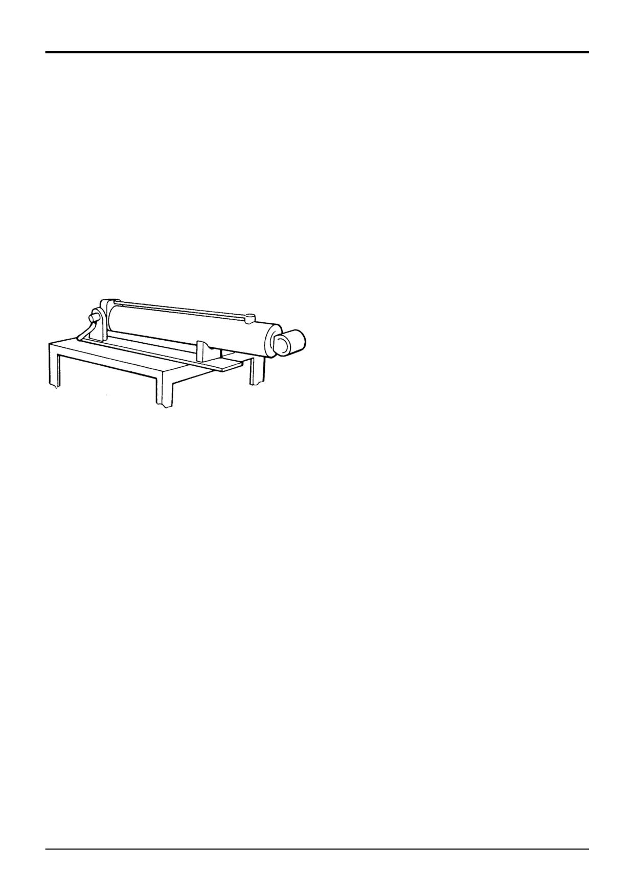
Place ram assembly on a locally manufactured strip/rebuild
Apply JCB Activator to threads of end cap and cylinder.
bench as shown.
Allow Activator to dry for 15 minutes before bringing into
contact with the JCB Threadlocker and Sealer (High
Strength).
Note: Neither the JCB Threadlocker and Sealer (High
Strength) nor Activator must be allowed to contact seals,
bearing rings, or 'O' rings.
Fit locking dowel 6 to piston head/rod as follows:
1
Fit 'O' ring 8 into piston head 7.
S263670
2
Fit piston head to piston rod and torque tighten to 405
Nm (300 lbf ft).
Slacken end cap 1 using special spanner (see Service
Tools), and remove the piston rod assembly 2 from the
3
New ram Shaft and piston head fitted.
cylinder.
-
If both are required, the following procedure should
! WARNING
be followed:
If air or hydraulic pressure is used to force out the piston
a Drill through piston head into piston rod. Use an
assembly, ensure that the end cap is securely fitted.
undersized diameter drill first as a guide and then
Severe injury can be caused by a suddenly released
drill with the correct size diameter drill to suit; refer
piston rod.
HYD 1-2
to the table for drill diameters and depths.
Position piston rod assembly on bench in place of ram
b Remove all swarf and contamination. Insert dowel 6
cylinder. Remove seal 4 and wear rings 3 and 5 from piston
into drilled hole, make sure tapped extractor hole is
head.
to outside.
Extract dowel 6 from the piston head using a metric screw
4
New piston head fitted on a pre-drilled piston rod.
(M3, M4, or M6 depending on ram size) threaded into the
-
Re-drill and dowel BOTH the piston head and
extractor hole.
piston rod at 90° from the existing drilled dowel
hole in the piston rod. Follow the procedures
Remove piston head from rod using special spanner (see
described in step 3.
Service Tools).
5
New piston rod fitted to a pre-drilled piston head.
Remove gland bearing and end cap 1 from piston rod and
-
Use the pre-drilled hole in the piston head. Care
remove the ‘O’ ring 9, wiper seal 10 and rod seal 11. Check
must be taken not to elongate the existing hole in
the end cap bearing for damage, scores or nicks. If
the piston head.
damaged, the bearing must be replaced as part of the end
cap assembly.
a Use a drill the same diameter as the pre-drilled hole
in the piston head to make a 'centre mark' in the
Ensure that metal components are free from scoring, nicks
piston rod. DO NOT drill the piston rod at this
and burrs. A damaged rod will impair the life of the seals.
stage.
Check the bore of the ram cylinder for damage.
...........continued
9803/3280
Issue 1
www.WorkshopManuals.co.ukSection E
Section E
Hydraulics
85 - 3
Hydraulic Rams
85 - 3
Dismantling and Assembly:
- Loader Lift Ram
- Loader Shovel Ram
- Boom Ram
- Bucket Ram
- Stabiliser Ram
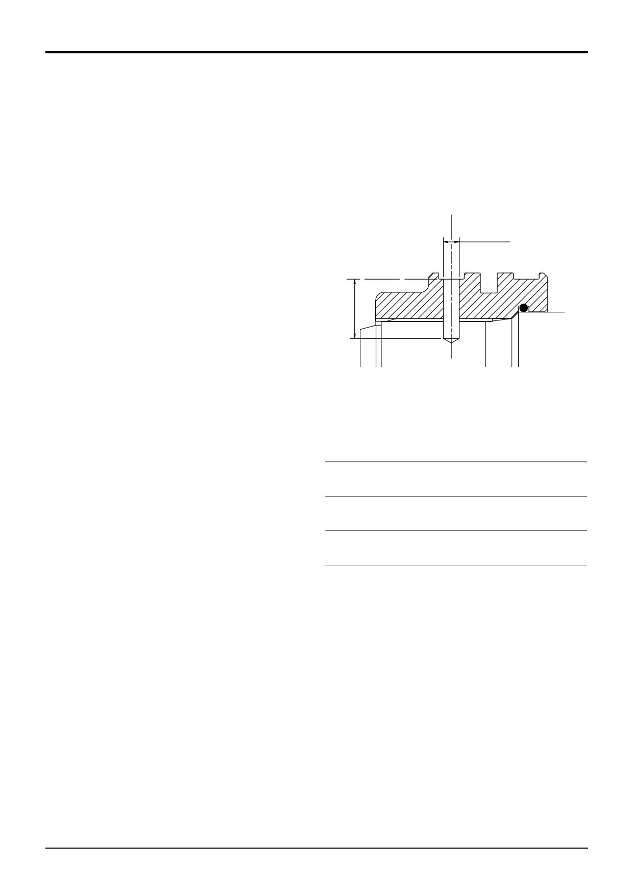
DRILLING DETAILS FOR PISTON HEAD RETENTION
Assembly (continued)
b Use an undersized diameter drill as a guide and drill
X
into the piston rod to the required depth (see table),
make sure the drill has centred correctly on the
'centre mark' made at step 5a.
c Use the correct size diameter drill to suit the dowel
and drill to the required depth (see table).
Y
d Remove all swarf and contamination, insert the
dowel.
Position cylinder on bench and install rod assembly into
cylinder.
A263750
Apply JCB Threadlocker and Sealer (High Strength) to first
three threads of cylinder, torque tighten the end cap to 678
(all dimensions in mm)
Nm (500 lbf ft).
Ram
Dowel
Guide Guide Dowel
Dowel
Size
Size
Drill Ø Drill
Drill Ø X
Drill
Note: If hydraulic oil contacts the uncured JCB Threadlocker
and Sealer (High Strength) a weakening of the bond will
Depth
Depth Y
result. Cure times vary according to the ambient
80 x 50
6Ø x 20
4
21
6.02/6.10
22/23
temperature. Allow a minimum of 2 hours between assembly
70 x 40
and filling the ram with oil.
Note: Cold weather operation. When operating in conditions
90 x 50
8Ø x 25
5
24
8.02/8.10
27/28
which are consistently below freezing, it is recommended
100 x 60
that the rams are operated slowly to their full extent before
110 x 60
12Ø x 30
8
28
12.02/12.10
32/33
commencing normal working.
110 x 65
Torque Settings
120 x 65
12Ø x 35
8
33
12.02/12.10
37/38
130 x 75
Item
Nm
kgf m
lbf ft
7
405
41.3
300
1
678
69.2
500
9803/3280
Issue 1
Section E
Section E
Hydraulics
86 - 1
Hydraulic Rams
86 - 1
19
20
13
14
22
1
21
12
11
10
3
9
4
5
8
6
7
18
16
17
15
S263740
2
6
5
4
3
1
7
8
12
14
13
11
S263730
9803/3280
Issue 1
www.WorkshopManuals.co.ukSection E
Section E
Hydraulics
86 - 2
Hydraulic Rams
86 - 2
Dismantling and Assembly
Assembly
- Dipper Ram
Clean threads of piston rod, piston head, end cap and
cylinder using a wire brush. Use JCB Cleaner/Degreaser to
Dismantling
ensure that all threads are free from grease, hydraulic oil and
The numerical sequence shown on the illustration is intended
sealant. Allow 15 minutes for solvent to dry before applying
as a guide to dismantling.
JCB Threadlocker and Sealer (High Strength).
For assembly the sequence should be reversed.
Ensure that lubricants used during assembly do not come
into contact with the JCB Threadlocker and Sealer (High
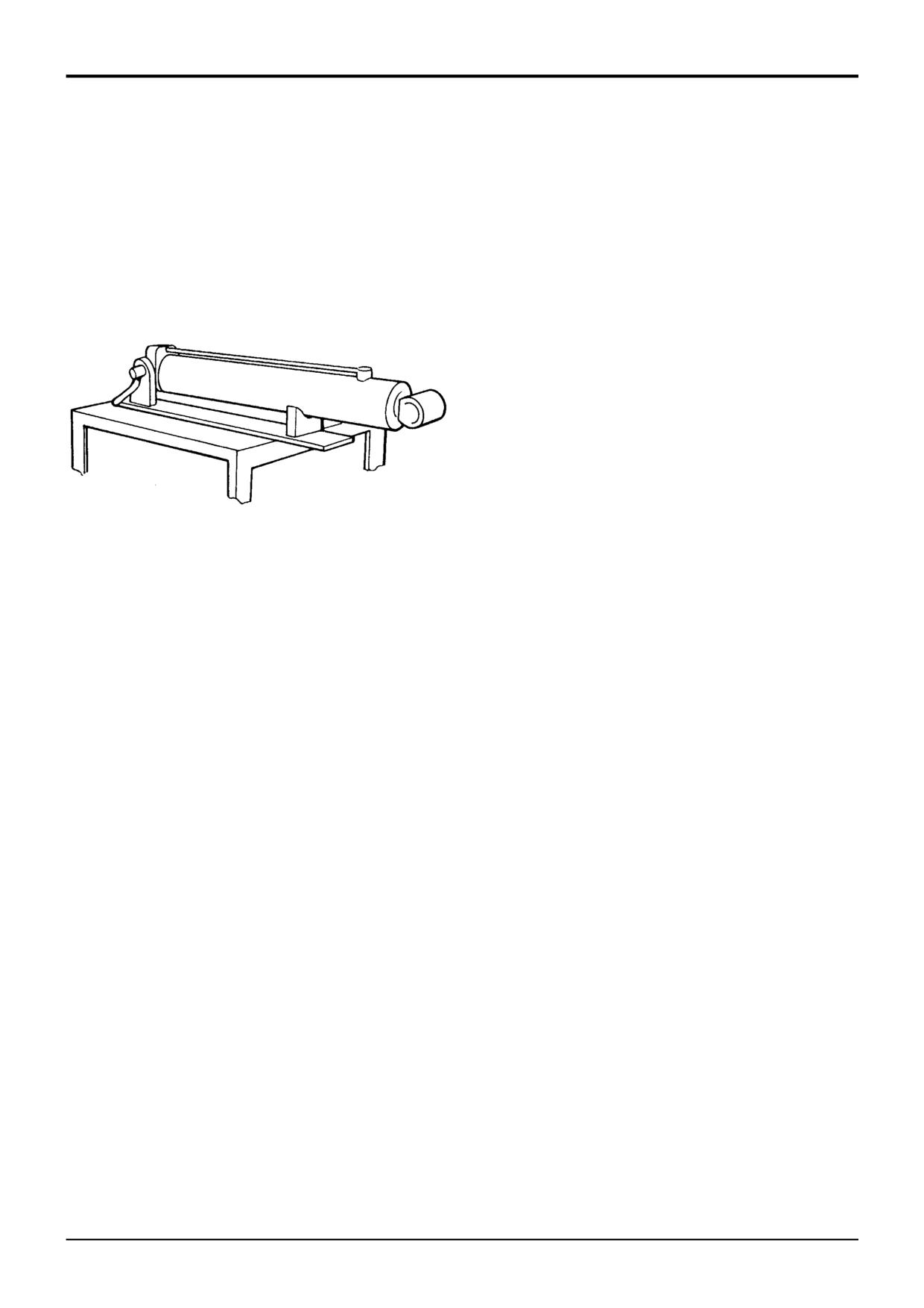
Place ram assembly on a locally manufactured strip/rebuild
Strength).
bench as shown.
Refer to JCB Ram Sealing Procedure for the correct
method of fitting seals to the end cap and piston head.
Apply JCB Activator to threads of end cap and cylinder.
Allow Activator to dry for 15 minutes before bringing into
contact with the JCB Threadlocker and Sealer (High
Strength).
Note: Neither the JCB Threadlocker and Sealer (High
Strength) nor Activator must be allowed to contact seals,
S263670
bearing rings, or 'O' rings.
Ensure that end damping spring 9 is engaged with collar 10
Slacken end cap 1 using special spanner (see Service
and piston head 7.
Tools), and remove the piston rod assembly 2 from the
cylinder.
Fit locking dowel 6 to piston head/rod as follows:
! WARNING
If air or hydraulic pressure is used to force out the piston
1
Fit 'O' ring 8 into piston head 7.
assembly, ensure that the end cap is securely fitted.
Severe injury can be caused by a suddenly released
2
Fit piston head to piston rod and torque tighten to 405
piston rod.
Nm (300 lbf ft).
HYD 1-2
3
New ram Shaft and piston head fitted.
Position piston rod assembly on bench in place of ram
-
If both are required, the following procedure should
cylinder. Remove seal 4 and wear rings 3 and 5 from piston
be followed:
head.
a Drill through piston head into piston rod. Use an
Extract dowel 6 from the piston head using a metric screw
undersized diameter drill first as a guide and then
(M3, M4, or M6 depending on ram size) threaded into the
drill with the correct size diameter drill to suit; refer
extractor hole.
to the table for drill diameters and depths.
Remove piston head from rod using special spanner (see
b Remove all swarf and contamination. Insert dowel 6
Service Tools).
into drilled hole, make sure tapped extractor hole is
to outside.
Remove gland bearing and end cap 1 from piston rod and
remove the ‘O’ rings 11 and 12, wiper seal 13 and rod seal
4
New piston head fitted on a pre-drilled piston rod.
14. Check the end cap bearing for damage, scores or nicks.
-
Re-drill and dowel BOTH the piston head and
If damaged, the bearing must be replaced as part of the end
piston rod at 90° from the existing drilled dowel
cap assembly.
hole in the piston rod. Follow the procedures
described in step 3.
Ensure that metal components are free from scoring, nicks
and burrs. A damaged rod will impair the life of the seals.
5
New piston rod fitted to a pre-drilled piston head.
-
Use the pre-drilled hole in the piston head. Care
Check the bore of the ram cylinder for damage.
must be taken not to elongate the existing hole in
the piston head.
...........continued
9803/3280
Issue 1
www.WorkshopManuals.co.ukSection E
Section E
Hydraulics
86 - 3
Hydraulic Rams
86 - 3
Dismantling and Assembly:
- Dipper Ram
Assembly (continued)
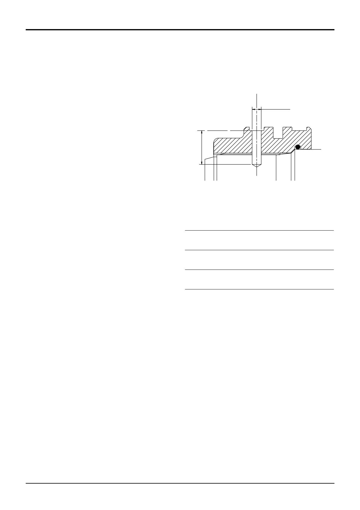
DRILLING DETAILS FOR PISTON HEAD RETENTION
a Use a drill the same diameter as the pre-drilled hole
in the piston head to make a 'centre mark' in the
piston rod. DO NOT drill the piston rod at this
X
stage.
b Use an undersized diameter drill as a guide and drill
into the piston rod to the required depth (see table),
make sure the drill has centred correctly on the
'centre mark' made at step 5a.
Y
c Use the correct size diameter drill to suit the dowel
and drill to the required depth (see table).
d Remove all swarf and contamination, insert the
dowel.
A263750
Position cylinder on bench and install rod assembly into
(all dimensions in mm)
cylinder.
Ram
Dowel
Guide
Guide
Dowel
Dowel
Apply JCB Threadlocker and Sealer (High Strength) to first
Size
Size
Drill Ø
Drill
Drill Ø X
Drill
three threads of cylinder, torque tighten the end cap to 678
Depth
Depth Y
Nm (500 lbf ft).
80 x 50
6Ø x 20
4
21
6.02/6.10
22/23
Note: If hydraulic oil contacts the uncured JCB Threadlocker
70 x 40
and Sealer (High Strength) a weakening of the bond will
result. Cure times vary according to the ambient
90 x 50
8Ø x 25
5
24
8.02/8.10
27/28
temperature. Allow a minimum of 2 hours between assembly
100 x 60
and filling the ram with oil.
110 x 60
12Ø x 30
8
28
12.02/12.10
32/33
Note: Cold weather operation. When operating in conditions
110 x 65
which are consistently below freezing, it is recommended
that the rams are operated slowly to their full extent before
120 x 65
12Ø x 35
8
33
12.02/12.10
37/38
commencing normal working.
130 x 75
Torque Settings
Item
Nm
kgf m
lbf ft
7
405
41.3
300
1
678
69.2
500
9803/3280
Issue 1
Section E
Section E
Hydraulics
87 - 1
Hydraulic Rams
87 - 1
2
3
4
5
1
6
10
9
8
7
11
12
16
14
15
13A
13
19
20
17
18
S263690
22
15
16
14
21
13
2
12
7
S263710
6
9
8
9803/3280
Issue 1
www.WorkshopManuals.co.ukSection E
Section E
Hydraulics
87 - 2
Hydraulic Rams
87 - 2
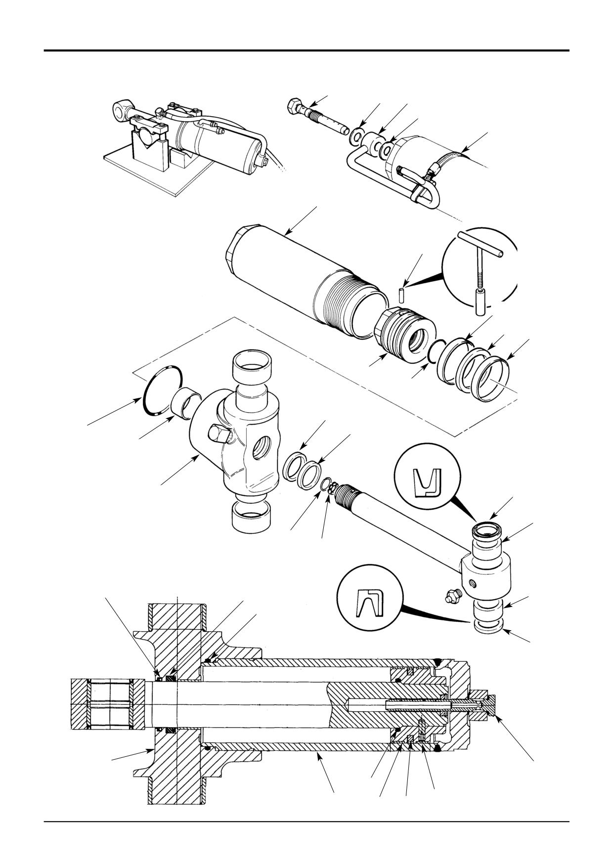
Dismantling and Assembly
Assembly
- Slew Ram
Clean threads of piston rod, piston head, end cap and
cylinder using a wire brush. Use JCB Cleaner/Degreaser to
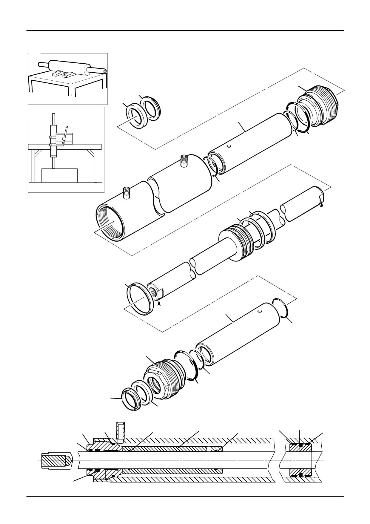
Dismantling
ensure that all threads are free from grease, hydraulic oil and
The numerical sequence shown on the illustration is intended
sealant. Allow 15 minutes for solvent to dry before applying
as a guide to dismantling.
JCB Threadlocker and Sealer (High Strength).
For assembly the sequence should be reversed.
Ensure that lubricants used during assembly do not come
into contact with the JCB Threadlocker and Sealer (High
Place ram assembly on a locally manufactured strip/rebuild
Strength).
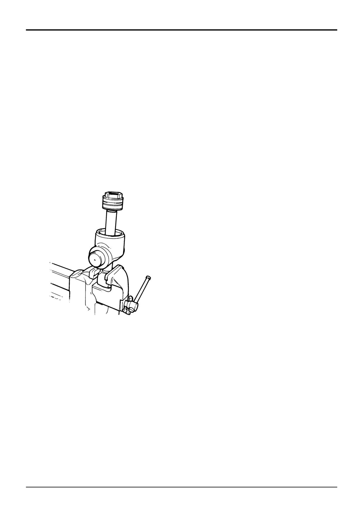
bench as shown, or alternatively, hold the ram in a suitable
vice taking care not to damage machined faces.
Refer to JCB Ram Sealing Procedure for the correct
method of fitting seals to the end cap and piston head.
Remove cylinder 6 using special spanner (see Service
Tools). Tap the cylinder off the piston head assembly using a
Apply JCB Activator to threads of end cap and cylinder.
suitable drift (e.g. nylon).
Allow Activator to dry for 15 minutes before bringing into
contact with the JCB Threadlocker and Sealer (High
Position the piston rod assembly in a vice, use soft jaws and
Strength).
stand the assembly vertical whilst clamping on the eye end.
Note: Neither the JCB Threadlocker and Sealer (High
Strength) nor Activator must be allowed to contact seals,
bearing rings, or 'O' rings.
Fit locking dowel 10 to piston head/rod as follows:
1
Fit 'O' ring 12 into piston head 11.
2
Fit piston head to piston rod and torque tighten to 405
Nm (300 lbf ft).
3
New ram Shaft and piston head fitted.
-
If both are required, the following procedure should
be followed:
a Drill through piston head into piston rod. Use an
undersized diameter drill first as a guide and then
drill with the correct size diameter drill to suit; refer
to the table for drill diameters and depths.
S266380
b Remove all swarf and contamination. Insert dowel
10 into drilled hole, make sure tapped extractor
hole is to outside.
Remove seal 8 and wear rings 7 and 9 from piston head.
Extract dowel 10 from the piston head using a metric screw
4
New piston head fitted on a pre-drilled piston rod.
threaded into the extractor hole.
-
Re-drill and dowel BOTH the piston head and
piston rod at 90° from the existing drilled dowel
Remove piston head from rod using special spanner (see
hole in the piston rod. Follow the procedures
Service Tools).
described in step 3.
Remove ‘O’ ring 12.
5
New piston rod fitted to a pre-drilled piston head.
-
Use the pre-drilled hole in the piston head. Care
Lift the end cap assembly 13 off the piston rod. Remove ‘O’
must be taken not to elongate the existing hole in
ring 14, rod wiper seal 15 and rod seal 16 from the end cap
the piston head.
assembly. Check the end cap bearing 13A for damage,
scores or nicks.
a Use a drill the same diameter as the pre-drilled hole
in the piston head to make a 'centre mark' in the
Item 18 is the metering orifice plate and item 17 its retaining
piston rod. DO NOT drill the piston rod at this
wire, do not remove these items unless problems with the
stage.
metering are suspected.
Ensure that metal components are free from scoring, nicks
...........continued
and burrs. A damaged rod will impair the life of the seals.
Check the bore of the ram cylinder for damage.
9803/3280
Issue 1
www.WorkshopManuals.co.ukSection E
Section E
Hydraulics
87 - 3
Hydraulic Rams
87 - 3
Dismantling and Assembly
- Slew Ram
Assembling (continued)
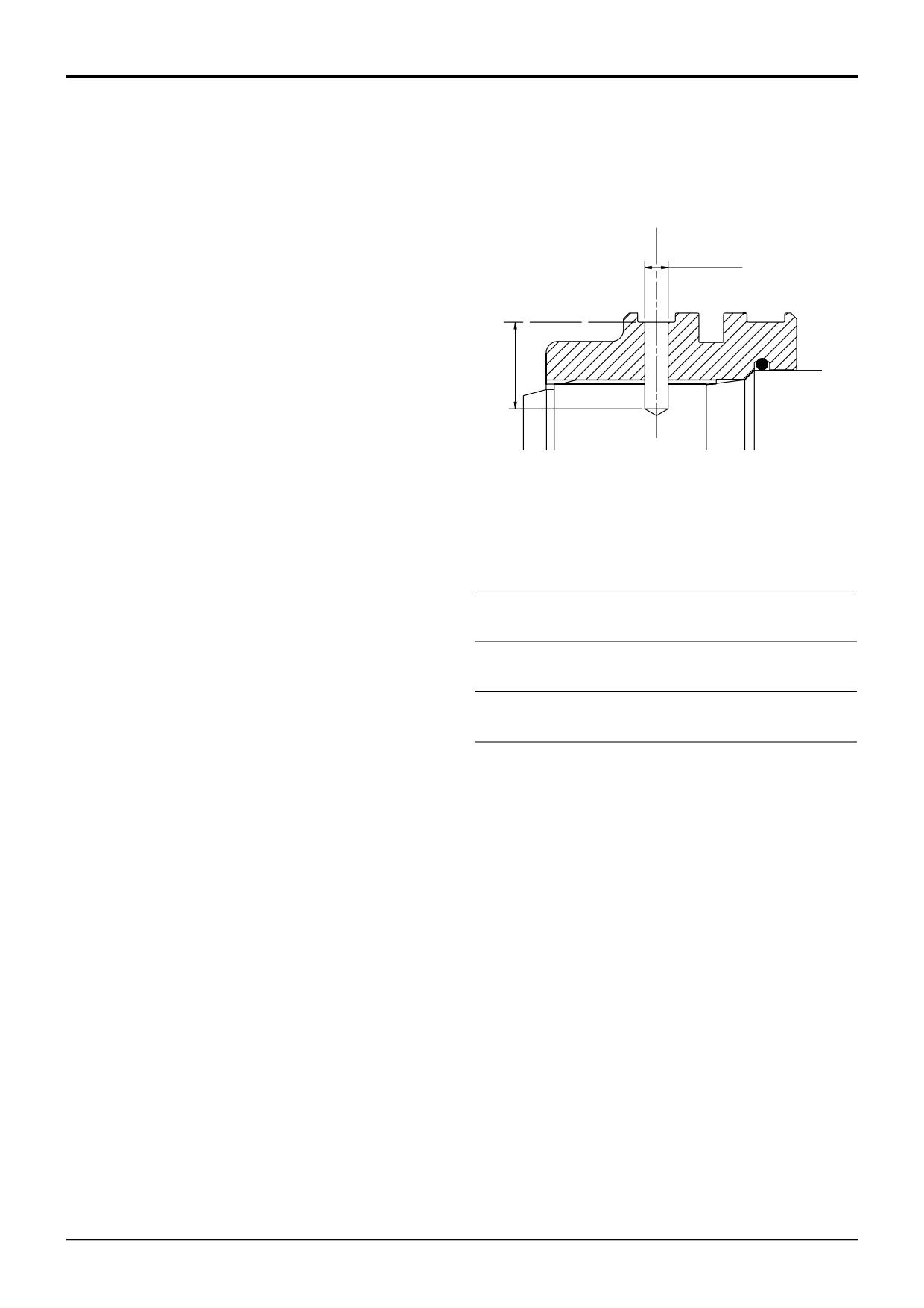
DRILLING DETAILS FOR PISTON HEAD RETENTION
b Use an undersized diameter drill as a guide and drill
into the piston rod to the required depth (see table),
X
make sure the drill has centred correctly on the
'centre mark' made at step 5a.
c Use the correct size diameter drill to suit the dowel
and drill to the required depth (see table).
Y
d Remove all swarf and contamination, insert the
dowel.
Install cylinder onto the rod assembly, make sure that the
cylinder is fitted square to the rod assembly. Firmly push the
cylinder over the piston head seals.
A263750
Apply JCB Threadlocker and Sealer (High Strength) to first
three threads of cylinder, torque tighten the cylinder to 678
(all dimensions in mm)
Nm (500 lbf ft).
Ram
Dowel
Guide
Guide
Dowel
Dowel
Note: If hydraulic oil contacts the uncured JCB Threadlocker
Size
Size
Drill Ø
Drill
Drill Ø X
Drill
and Sealer (High Strength) a weakening of the bond will
Depth
Depth Y
result. Cure times vary according to the ambient
temperature. Allow a minimum of 2 hours between assembly
80 x 50
6Ø x 20
4
21
6.02/6.10
22/23
and filling the ram with oil.
70 x 40
Note: Cold weather operation. When operating in conditions
90 x 50
8Ø x 25
5
24
8.02/8.10
27/28
which are consistently below freezing, it is recommended
100 x 60
that the rams are operated slowly to their full extent before
commencing normal working.
110 x 60
12Ø x 30
8
28
12.02/12.10
32/33
110 x 65
Position pipe assembly in correct position and torque tighten
probe assembly 2 to 75Nm (55 lbf ft; 7.6 kgf m). DO NOT
120 x 65
12Ø x 35
8
33
12.02/12.10
37/38
over-tighten the probe.
130 x 75
Make sure seals 19 and 21 are fitted the correct way as
shown.
Torque Settings
Item
Nm
kgf m
lbf ft
11
405
41.3
300
6
678
69.2
500
9803/3280
Issue 1
Section E
Hydraulics
Section E
88 - 1
Hydraulic Rams
88 - 1
A
1
4
A258580
5
B
7
6
8
A258590
8
2
D
3
2
7
C
8
1
8
6
4
5
322580
2
3
1
6
7
2
8
8
4
5
A326710
9803/3280
Issue 1