JCB 3CX, 4CX, 214e, 214, 215, 217 & VARIANTS Backhoe Loader. Service Manual - page 18
Section E
Hydraulics
Section E
50 - 15
Loader Valve - Fixed Flow
50 - 15
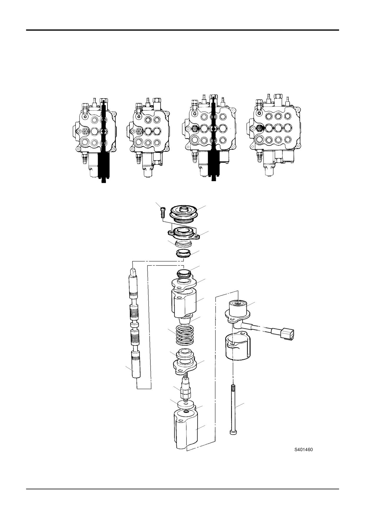
Dismantling and Assembly
Assembly
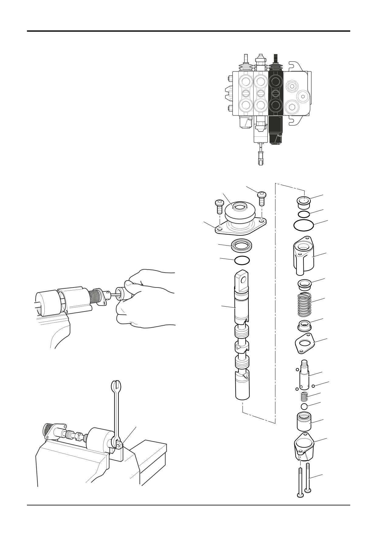
Float Spool - Manual
1
Fit the boot 2 to the seal plate 3.
The numerical sequence shown on the illustration is intended
as a guide to dismantling.
2
Fit a new lipseal 5 into the valve block, ensure square.
Fit wiper 4 on top of lipseal.
For assembly the sequence should be reversed.
3
Fit the seal plate and boot assembly to valve block but
The following points MUST be avoided when dismantling
do not torque tighten capscrews 1 at this stage. Ensure
wiper locates into seal plate.
and assembling the valve:
4
Use clean hydraulic oil as a lubricant. From the bottom,
•
CONTAMINATION
insert spool through the valve block, do not use
•
DAMAGE TO SPOOL
excessive force when fitting, a turning motion should
•
DAMAGE TO SEAL GROOVES
ease the spool through the valve block.
All or any of the above points may result in possible
5
Check that the tang end of the spool passes through
problems with the valve.
the boot without dislodging or damaging the boot.
Ensure that the tang aligns with the control rod and
Dismantling
that the boot is not distorted and is located in the spool
Remove the lever linkage from the tang (lever) end of the
land.
spool.
6
Torque tighten cap screws 1.
When removing 'O' rings and seals, use an appropriately
7
When fitting detent pin 20, clean the threads thoroughly
rounded tool that WILL NOT cause any damage to the spool
using JCB Cleaner/Degreaser, leave it for 10 minutes
or seal grooves, for instance, item 4, which is a wiper seal
then apply a small quantity of JCB Threadlocker and
and is a press fit in the counterbore.
Sealer to the threads of the spool.
Care must be taken to ensure that the spool 13 is not
8
Apply grease liberally balls 10, this will help to hold the
damaged when removing it from the valve block.
balls in position whilst assembling.
Carefully remove collar 9 and collect detent balls 10.
9
Renew 'O' ring 15. Make sure the 'O' ring is not
trapped or damaged.
Using tool 992/10100 to hold the spool, remove circlip 16,
plug 17, ball 18 and spring 19. Unscrew detent pin 20 and
10
Fit seal 15 and seal plate 14 to the valve block section.
remove spring 22 and cups 21 and 23.
Torque tighten capscrew 6 on completion.
Check for surface contamination on the under side of the
Re-connect the lever mechanism to the tang (lever) end of
seal plates 3 and 14. Clean if necessary. Check for the
the spool.
flatness of the seal plate. If found to be bent - replace with
new (any work previously carried out on this valve may have
Run the engine and inspect the valve for external leaks.
resulted in the bending of the seal plate).
Torque Settings
Item
Nm
kgf m
lbf ft
1
9.5
0.96
7
6
9.5
0.96
7
20
9.5
0.96
7
9803/3280
Issue 1
Section E
Hydraulics
Section E
50 - 16
Loader Valve - Fixed Flow
50 - 16
1
1A
2
3
4
11
10
9
6
18
17
16
8
12
15
14
5
13
7
9803/3280
Issue 1
Section E
Hydraulics
Section E
50 - 17
Loader Valve - Fixed Flow
50 - 17
Dismantling and Assembly
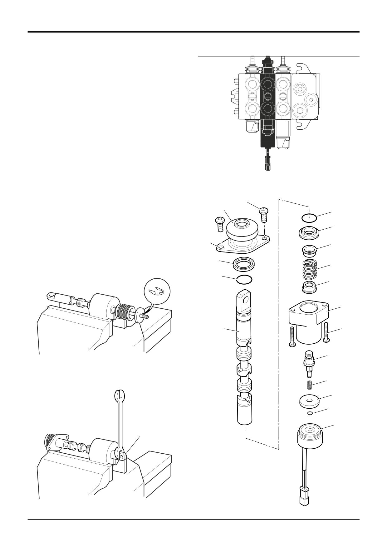
Electric Detent Spool - Manual
Assembly
The numerical sequence shown on the illustration is intended
as a guide to dismantling.
1
Fit the boot 1A to the seal plate 2.
For assembly the sequence should be reversed.
2
Fit a new lipseal 4 into the valve block, ensure square.
The following points MUST be avoided when dismantling
Fit wiper 3 on top of lipseal.
and assembling the valve:
3
Fit the seal plate and boot assembly to valve block but
•
CONTAMINATION
do not torque tighten capscrews 1 at this stage. Ensure
•
DAMAGE TO SPOOL
wiper locates into seal plate.
•
DAMAGE TO SEAL GROOVES
4
Use clean hydraulic oil as a lubricant. From the bottom,
All or any of the above points may result in possible
insert spool through the valve block, do not use
problems with the valve.
excessive force when fitting, a turning motion should
ease the spool through the valve block.
Dismantling
5
Check that the tang end of the spool passes through
When removing 'O' rings and seals, use an appropriately
the boot without dislodging or damaging the boot.
Ensure that the tang aligns with the control rod and
rounded tool that WILL NOT cause any damage to the spool
that the boot is not distorted and is located in the spool
or seal grooves, for instance, item 3, which is a wiper seal
land.
and is a press fit in the counterbore.
6
Torque tighten cap screws 1.
Care must be taken to ensure that the spool 12 is not
damaged when removing it from the valve block.
7
When fitting spool end 15, clean the threads thoroughly
using JCB Cleaner/Degreaser, leave it for 10 minutes
Use tool 992/10100 to hold the spool, remove circlip 13 and
then apply a small quantity of JCB Threadlocker and
'clapper' 14. Unscrew spool end 15 and remove spring 17
Sealer to the threads of the spool.
with cups 16 and 18.
8
Make sure that the chamfer on item 14 faces away from
Check for surface contamination on the under side of the
the solenoid, item 6.
seal plates 2, 8 and 10. Clean if necessary. Check for the
flatness of the seal plate. If found to be bent - replace with
9
Renew lipseal 11. Make sure the lipseal is not trapped
new (any work previously carried out on this valve may have
or damaged.
resulted in the bending of the seal plate).
10
Fit lipseal 11 and seal plate 10 to the valve block
section. Torque tighten capscrew 5 on completion.
Check the operation of the solenoid 6 after assembly by
connecting a 12V supply. The spool should be held when it
is pushed into the detent position and returned when the
supply is disconnected.
Run the engine and inspect the valve for external leaks.
Torque Settings
Item
Nm
kgf m
lbf ft
1
9.5
0.96
7
5
9.5
0.96
7
15
9.5
0.96
7
9803/3280
Issue 1

Section E
Hydraulics
Section E
50 - 24
Loader Valve - Fixed Flow
50 - 24
1B
3B
4B
5B
1C
6B
7B
2C
8B
9B
3A
4A
1A
E
8A
2A
1A
7A
6A
5A
12B
11B
10B
2C
1C
A402610
9803/3280
Issue 1
Section E
Hydraulics
Section E
50 - 25
Loader Valve - Fixed Flow
50 - 25
Dismantling and Assembly
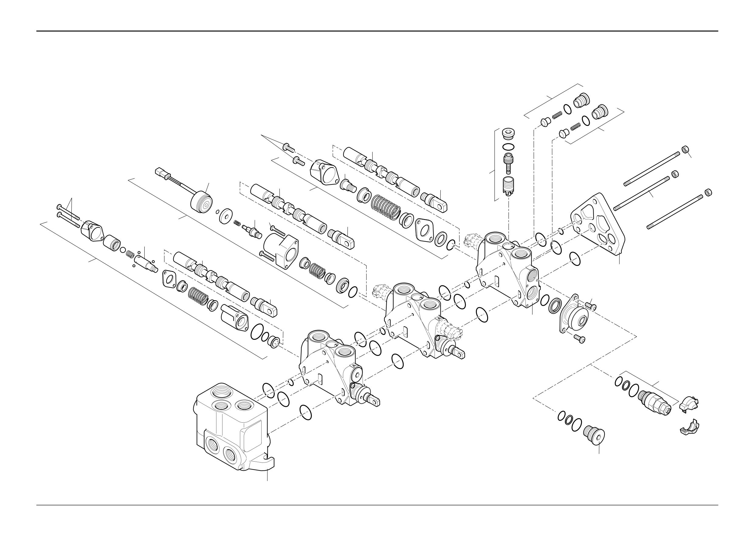
Bolt on Auxiliary Spool Section
Body and Spool
The numerical sequence shown on the illustration is intended
Torque Settings
as a guide to dismantling.
Item
Nm
kgf m
lbf ft
Two dismantling sequences are shown:
1A
19
1.9
14
Components prefixed A - inlet section, valve body and non-
2A
45
4.6
33
return valve.
1B, 3B
8 - 11
0.8 - 1.1
6 - 8
Components prefixed B - valve spool components.
1C
40 - 49
4 - 5
30 - 36
The valve spool components can be dismantled and
assembled with the valve body 5A still assembled to the
loader valve E if required.
For assembly the sequence should be reversed.
The following points MUST be avoided when dismantling
and assembling the valve:
• CONTAMINATION
• DAMAGE TO SPOOL
• DAMAGE TO SEAL GROOVES
All or any of the above points may result in possible
problems with the valve.
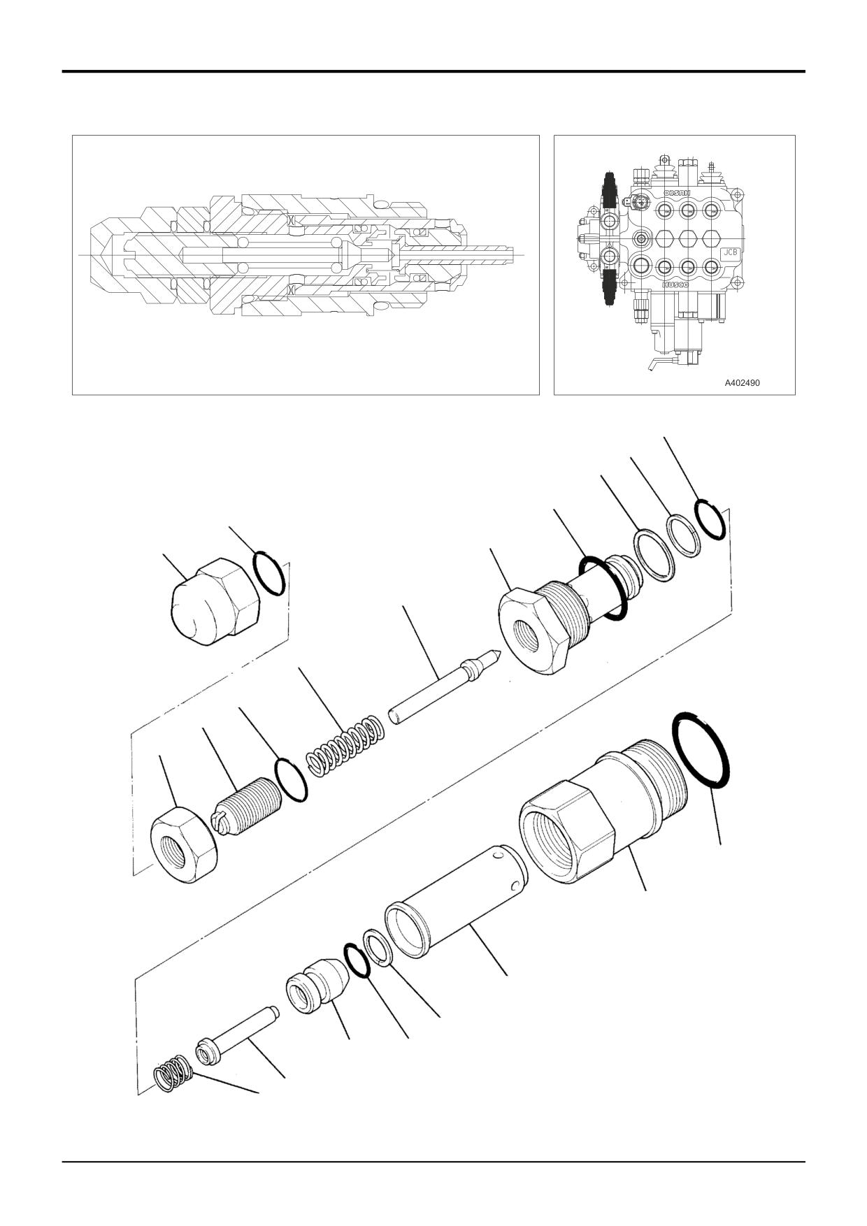
For dismantling and assembly of the auxiliary relief valves
1C, see Bolt on Auxiliary Spool Section - Auxiliary Relief
Valves.
When Dismantling
When removing 'O' rings and seals, use an appropriately
rounded tool that WILL NOT cause any damage to the spool
or seal grooves.
When dismantling the spool hold a rod through the eye end
of the spool to prevent it rotating when undoing the screw at
the opposite end.
Inspection
Inspect the valve components for signs of scratches, nicks
or any other type of damage. Renew damaged components
as required.
When Assembling
Renew 'O' ring seals 4A, 8A, and 2C. Make sure the 'O' ring
seals are not trapped or damaged.
Renew wiper seals 8B and 11B, and spool seals 9B and
12B, note the correct seal orientation shown at X. When
fitting seals 9B and 12B make sure they are square to the
valve body.
9803/3280
Issue 1
Section E
Hydraulics
Section E
50 - 26
Loader Valve - Fixed Flow
50 - 26
A402630
13
14
11
12
2
10
1
9
8
6
7
5
4
3
15
20
16
19
S402620
18
17
9803/3280
Issue 1
Section E
Hydraulics
Section E
50 - 27
Loader Valve - Fixed Flow
50 - 27
Dismantling and Assembly
Bolt on Auxiliary Spool Section
Auxiliary Relief Valve (ARV)
The numerical sequence shown on the illustration is
intended as a guide to dismantling.
For assembly the sequence should be reversed.
Great care should be taken when dismantling and
assembling a valve to avoid the following:-
Contamination
Damage to spools
Damage to seal grooves
Any of the above may result in possible problems with the
operation of the valve.
When Dismantling
When removing 'O' Rings and seals, use an appropriatly
rounded tool that WILL NOT cause any damage to the seal
grooves.
Discard ALL 'O' Rings and back-up rings. DO NOT use
worn or damaged items.
Inspection
Inspect the valve components for scratches, nicks or any
other type of damage, replace with new if required.
When Assembling
Renew all 'O' rings and back-up rings.
Lubricate parts with JCB Hydraulic Fluid before assembling.
Make sure that all the parts move freely.
Make sure that the ‘O’ rings and back-up rings are fitted the
correct way, items 13, 14 and 19, 20.
Adjust pressure setting as required, refer to Service
Procedures, Pressure Testing - MRV and ARV’s.
Torque Settings
Item
Nm
kgf m
lbf ft
1
62
6.4
46
5
5.4 - 8.2
0.55 - 0.83
4 - 6
10
41 - 68
4.15 - 6.9
30 - 50
9803/3280
Issue 1
Section E
Hydraulics
Section E
51 - 1
Loader Valve - Fixed Flow
51 - 1
Dismantling and Assembly
Precision Control (Servo)
(Machines from January 2003)
12
7A
12
6
1
7B
11
8A
6
7C
9A
7
5
8
8B 8C
8D
9B
6
9
2
7D
9C
3
10
10A
A403910
4
9803/3280
Issue 1
Section E
Hydraulics
Section E
51 - 2
Loader Valve - Fixed Flow
51 - 2
Dismantling and Assembly
Precision Control (Servo)
(Machines from January 2003)
Dismantling
The loader valve block is a ‘sandwich type’, which is made
Service Spools
Care must be taken to ensure that the spools 6 are not
up of a number of separate sections. The illustration shown
on the opposite page is intended as a guide to dismantling.
damaged when removing them from the block. Note that all
Be sure to note the location of all components when
spools may be similar in appearance but must not be
dismantling. Although some components may appear to be
interchanged as they are matched to their bores.
identical they are not interchangeable. Make sure that
Standard Spool
components are assembled in their original positions.
The dismantling and assembly procedures for the standard
1
Remove the loader valve block from the machine.
spool assembly 7 are detailed separately, refer to Standard
Spool.
2
Remove the three tie rod nuts 1.
Electric Detent Spool
3
Carefully separate and remove the end plate 2 followed
The dismantling and assembly procedures for the electric
by the remaining service sections 3. If the inlet section 4
detent spool assembly 8 are detailed separately, refer to
is to be replaced, remove and retain the tie rods 5.
Electric Detent Spool.
Mechanical Detent Spool
Assembly
The dismantling and assembly procedures for the
mechanical detent spool assembly 9 are detailed separately,
Assembly is the reverse of the dismantling sequence.
refer to Mechanical Detent Spool.
1
Clean the valve components in an appropriate solvent.
Auxiliary Relief Valves
Ensure that the mating faces of the valve sections are
The A.R.V's 10 appear identical but have various pressure
thoroughly clean before assembly.
settings, refer to Technical Data. Ensure that they are
correctly adjusted and fitted in their specified positions.
2
Renew the ‘O’ rings located between the valve sections.
The dismantling and assembly procedures for the ARV’s are
Make sure the ‘O’ ring seals are not trapped or
detailed separately, refer to Excavator Valve, Dismantling
damaged.
and Assembly - Auxiliary Relief Valves (ARV’s).
3
Lubricate parts with JCB Hydraulic Fluid before
Pressure Compensator Valves
assembling. Make sure that all the parts move freely.
Each of the pressure compensator valves 11 can be
removed as shown. Note that all valves are identical in
Torque Settings
appearance. Note that components are not interchangeable.
Item
Nm
kgf m
lbf ft
Load Hold Check Valves
1
35
3.6
25.8
Each of the load hold check valves 12 can be removed as
7A
10
1
7.4
shown. Note that all valves are identical in appearance.
7B
10
1
7.4
Ensure good condition of seating faces on poppets and on
7C
10
1
7.4
the mating faces in the valve block.
7D
10
1
7.4
8A
20
2
14.8
8B
10
1
7.4
8C
10
1
7.4
8D
10
1
7.4
9A
10
1
7.4
9B
10
1
7.4
9C
10
1
7.4
10
70
7.1
51.6
10A
70
7.1
51.6
11
60
6.1
44.3
12
30
3
22.1
9803/3280
Issue 1

Section E
Hydraulics
Section E
51 - 3
Loader Valve - Fixed Flow
51 - 3
Dismantling and Assembly
A
A
A
Precision Control (Servo)
(Machines from January 2003)
LS
Standard Spool
P
B
B
B
T
A403690
1
2
15
14
3
13
4
A
5
12
11
8
10
A403950
9
7
B
16
6
A403990
A404060
9803/3280
Issue 1
Section E
Hydraulics
Section E
51 - 4
Loader Valve - Fixed Flow
51 - 4
Dismantling and Assembly
Precision Control (Servo)
(Machines from January 2003)
Standard Spool
Removal
Inspection
It is possible to remove a spool without removing the loader
1
Inspect the valve components for scratches, pitting,
valve block from the machine. The centring spring 11 is at
corrosion or any other type of damage.
the bottom, so the spool must be removed from the bottom.
Assembly
1
Gain access to the loader valve and disconnect and
blank any hoses or pipes which may interfere with the
Assembly is the reverse of the dismantling sequence.
removal of the spool.
1
Clean the valve components in an appropriate solvent.
2
Disconnect the control rod linkage from the spool
tongue.
2
Lubricate parts with JCB Hydraulic Fluid before
assembling. Make sure that all the parts move freely.
3
Remove the screws 1, boot 2 and plate 3.
3
Renew lip seals 4 and 14, and 'O' rings 5 and 15.
4
Remove the screws 6, cover 7 and carefully withdraw
the spool assembly from the valve body.
Note: The lip seal MUST be fitted carefully onto the end of
the spool to ensure that it is not damaged by the spool lands
Dismantling
and that its tightness property does not deteriate. The metal
part of the seal should be on the outside.
Great care should be taken when dismantling and
assembling a valve to avoid the following:-
Torque Settings
• Contamination
Item
Nm
kgf m
lbf ft
1
10
1
7.4
• Damage to spools
6
10
1
7.4
• Damage to seal grooves
9
10
1
7.4
16
10
1
7.4
Any of the above may result in possible problems with the
operation of the valve.
1
Hold the spool assembly in a vice using the spool clamp
(service tool no. TBA, refer to Service Tools) as shown
at A.
Tongue Replacement (if necessary)
2
Unscrew the spool end 9 and remove the centring
1
Hold the spool assembly in a vice using the spool clamp
spring 11 with spring retainers 10 and 12. It may be
(service tool no. TBA, refer to Service Tools).
necessary to pre-heat the spool to 200° C in an oven or
with a heat gun to remove the spool end.
2
Loosen the tongue 16 with an open ended wrench as
shown at B. It may be necessary to pre-heat the spool
Note: When removing 'O' Rings and seals, use an
to 200° C in an oven or with a heat gun to dismantle the
appropriatly rounded tool that WILL NOT cause any damage
spool.
to the seal grooves.
Note: DO NOT use a welding torch to heat the tongue as
Discard ALL 'O' Rings and back-up rings. DO NOT use worn
deformation of the spool may result.
or damaged items.
9803/3280
Issue 1
Section E
Hydraulics
Section E
51 - 5
Loader Valve - Fixed Flow
51 - 5
Dismantling and Assembly
A
A
A
Precision Control (Servo)
(Machines from January 2003)
LS
Electric Detent Spool
P
B
B
B
T
A403970
1
2
18
17
3
16
4
15
5
14
A
8
9
7
13
A404070
12
11
10
B
6
19
A404060
A404000
9803/3280
Issue 1
Section E
Hydraulics
Section E
51 - 6
Loader Valve - Fixed Flow
51 - 6
Dismantling and Assembly
Precision Control (Servo)
(Machines from January 2003)
Electric Detent Spool
Removal
Inspection
It is possible to remove a spool without removing the loader
1
Inspect the valve components for scratches, pitting,
valve block from the machine. The centring spring 15 is at
corrosion or any other type of damage.
the bottom, so the spool must be removed from the bottom.
Assembly
1
Gain access to the loader valve and disconnect and
blank any hoses or pipes which may interfere with the
Assembly is the reverse of the dismantling sequence.
removal of the spool.
1
Clean the valve components in an appropriate solvent.
2
Disconnect the control rod linkage from the spool
tongue.
2
Lubricate parts with JCB Hydraulic Fluid before
assembling. Make sure that all the parts move freely.
3
Remove the screws 1, boot 2 and plate 3.
3
Renew lip seal 4 and 'O' rings 5 and 18.
4
Unscrew the solenoid 6 from the housing 8. Remove the
screws 7, housing 8 and carefully withdraw the spool
Note: The lip seal MUST be fitted carefully onto the end of
assembly from the valve body.
the spool to ensure that it is not damaged by the spool lands
and that its tightness property does not deteriate. The metal
Dismantling
part of the seal should be on the outside.
Great care should be taken when dismantling and
Torque Settings
assembling a valve to avoid the following:-
Item
Nm
kgf m
lbf ft
• Contamination
1
10
1
7.4
7
10
1
7.4
• Damage to spools
13
10
1
7.4
• Damage to seal grooves
19
10
1
7.4
Any of the above may result in possible problems with the
operation of the valve.
1
Hold the spool assembly in a vice using the spool clamp
(service tool no. TBA, refer to Service Tools) as shown
at A.
2
Remove the circlip 10, disc 11 and spring 12.
Tongue Replacement (if necessary)
3
Unscrew the spool end 13 and remove the centring
1
Hold the spool assembly in a vice using the spool clamp
spring 15 with spring retainers 14 and 16. It may be
(service tool no. TBA, refer to Service Tools).
necessary to pre-heat the spool to 200° C in an oven or
with a heat gun to remove the spool end.
2
Loosen the tongue 19 with an open ended wrench as
shown at B. It may be necessary to pre-heat the spool
Note: When removing 'O' Rings and seals, use an
to 200° C in an oven or with a heat gun to dismantle the
appropriatly rounded tool that WILL NOT cause any damage
spool.
to the seal grooves.
Note: DO NOT use a welding torch to heat the tongue as
Discard ALL 'O' Rings and back-up rings. DO NOT use worn
deformation of the spool may result.
or damaged items.
9803/3280
Issue 1
Section E
Hydraulics
Section E
51 - 7
Loader Valve - Fixed Flow
51 - 7
Dismantling and Assembly
A
A
A
Precision Control (Servo)
(Machines from January 2003)
LS
Mechanical Detent Spool
P
B
B
B
T
A403980
1
2
21
20
3
19
4
18
5
17
A
16
8
15
14
A404080
13
12
11
10
B
9
22
7
6
A404060
A404010
9803/3280
Issue 1
Section E
Hydraulics
Section E
51 - 8
Loader Valve - Fixed Flow
51 - 8
Dismantling and Assembly
Precision Control (Servo)
(Machines from January 2003)
Mechanical Detent Spool
Removal
Inspection
It is possible to remove a spool without removing the loader
1
Inspect the valve components for scratches, pitting,
valve block from the machine. The centring spring 16 is at
corrosion or any other type of damage.
the bottom, so the spool must be removed from the bottom.
Assembly
1
Gain access to the loader valve and disconnect and
blank any hoses or pipes which may interfere with the
Assembly is the reverse of the dismantling sequence.
removal of the spool.
1
Clean the valve components in an appropriate solvent.
2
Disconnect the control rod linkage from the spool
tongue.
2
Lubricate parts with JCB Hydraulic Fluid before
assembling. Make sure that all the parts move freely.
3
Remove the screws 1, boot 2 and plate 3.
3
Renew lip seal 4 and 'O' rings 5, 19 and 20.
4
Remove the screws 6, cover 7 and carefully withdraw
the spool assembly from the valve body.
Note: The lip seal MUST be fitted carefully onto the end of
the spool to ensure that it is not damaged by the spool lands
Dismantling
and that its tightness property does not deteriate. The metal
part of the seal should be on the outside.
Great care should be taken when dismantling and
assembling a valve to avoid the following:-
Torque Settings
• Contamination
Item
Nm
kgf m
lbf ft
1
10
1
7.4
• Damage to spools
6
10
1
7.4
• Damage to seal grooves
13
10
1
7.4
22
10
1
7.4
Any of the above may result in possible problems with the
operation of the valve.
1
Hold the spool assembly in a vice using the spool clamp
(service tool no. TBA, refer to Service Tools) as shown
at A.
2
Use a metal rod (min. length 80 mm x 6 mm diameter)
to push on the central ball 10 whilst extracting the
detent bush 9 as shown. Mark the orientation of the
bush to ensure that it is fitted the correct way round on
re-assembly.
3
Carefully remove the balls 10 and 12, and the spring 11.
Tongue Replacement (if necessary)
4
Unscrew the spool end 13 and remove the centring
1
Hold the spool assembly in a vice using the spool clamp
spring 16 with spring retainers 15 and 17. It may be
(service tool no. TBA, refer to Service Tools).
necessary to pre-heat the spool to 200° C in an oven or
with a heat gun to remove the spool end.
2
Loosen the tongue 16 with an open ended wrench as
shown at B. It may be necessary to pre-heat the spool
Note: When removing 'O' Rings and seals, use an
to 200° C in an oven or with a heat gun to dismantle the
appropriatly rounded tool that WILL NOT cause any damage
spool.
to the seal grooves.
Note: DO NOT use a welding torch to heat the tongue as
Discard ALL 'O' Rings and back-up rings. DO NOT use worn
deformation of the spool may result.
or damaged items.
9803/3280
Issue 1
Section E
Hydraulics
Section E
55 - 1
Loader Valve - Variable Flow
55 - 1
Removal and Replacement
Replacement
! WARNING
Make the machine safe before working underneath it.
Replacement is a reversal of the removal sequence.
Park the machine on level ground, lower the arms. Apply
the parking brake, put the transmission in neutral and
! WARNING
stop the engine. Chock both sides of all four wheels.
Fine jets of hydraulic fluid at high pressure can penetrate
the skin. Do not use your fingers to check for hydraulic
Disconnect the battery, to prevent the engine being
fluid leaks. Do not put your face close to suspected
started while you are beneath the machine.
GEN-1-2
leaks. Hold a piece of cardboard close to suspected
leaks and then inspect the cardboard for signs of
hydraulic fluid. If hydraulic fluid penetrates your skin, get
! DANGER
medical help immediately.
Hydraulic Pressure
INT-3-1-10/1
Hydraulic fluid at system pressure can injure you. Before
disconnecting or connecting hydraulic hoses, stop the
After replacement check the auxiliary relief valve (A.R.V.)
engine and operate the controls to release pressure
pressure settings.
trapped in the hoses. Make sure the engine cannot be
started while the hoses are open.
Note: All hydraulic adapters that are installed together with a
INT-3-1-11/1
bonded sealing washer must also have sealant (JCB
Threadseal) applied to the threads of the adapter.
Removal
1
Operate the valve block levers back and forth to vent
residual pressure.
2
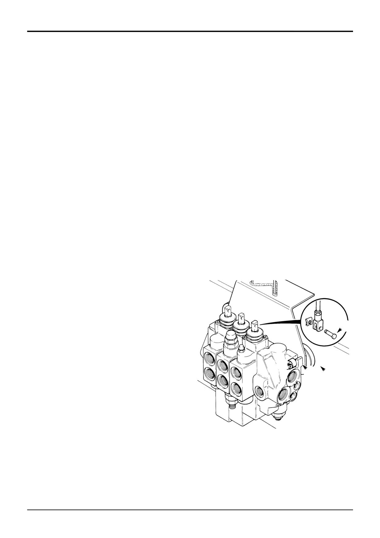
Remove clevis pins A to disconnect the control levers
from the valve block spools.
3
Disconnect all hydraulic hoses from the valve block and
plug all orifices to prevent ingress of dirt. Label each
hose before disconnecting, this will ensure correct
position when refitting.
4
Loosen and remove nuts B, spacers C, the loader valve
and resilient mounts D.
A
Inspection
Inspect the resilient mounts D for damage, cracking etc. If
the mounts are suspect, then replace them with new ones.
B
C D
S273910
9803/3280
Issue 1
Section E
Hydraulics
Section E
55 - 2
Loader Valve - Variable Flow
55 - 2
Dismantling and Assembly
Priority Inlet Section
7
8
5
1
6
2
3
3
16
3
17
4
8
4
7
5
5
4
14
14
15
13
13
11
11
12
12
A
10
10
9
9
18
17
S276050
16
A276060
9803/3280
Issue 1
Section E
Hydraulics
Section E
55 - 3
Loader Valve - Variable Flow
55 - 3
Dismantling and Assembly
Assembly
Priority Inlet Section
Renew all 'O' rings and back-up rings.
The numerical sequence shown on the illustration is
intended as a guide to dismantling.
Lubricate parts with JCB Hydraulic Fluid before assembling.
Make sure that all the parts move freely.
For assembly the sequence should be reversed.
Make sure that the 'O' rings and back-up rings are fitted the
The following points MUST be avoided when dismantling
correct way, items 11 and 12
and assembling the valve:
ALWAYS fit three shim (item 5) in between each valve block
•
CONTAMINATION
section as shown.
•
DAMAGE TO SPOOL
•
DAMAGE TO SEAL GROOVES
After assembly, make sure the steering operates correctly.
The steer circuit will always have priority (see descriptions).
All or any of the above points may result in possible
problems with the valve.
Torque Settings
Dismantling
Item
Nm
kgf m
lbf ft
1
41
4.1
30
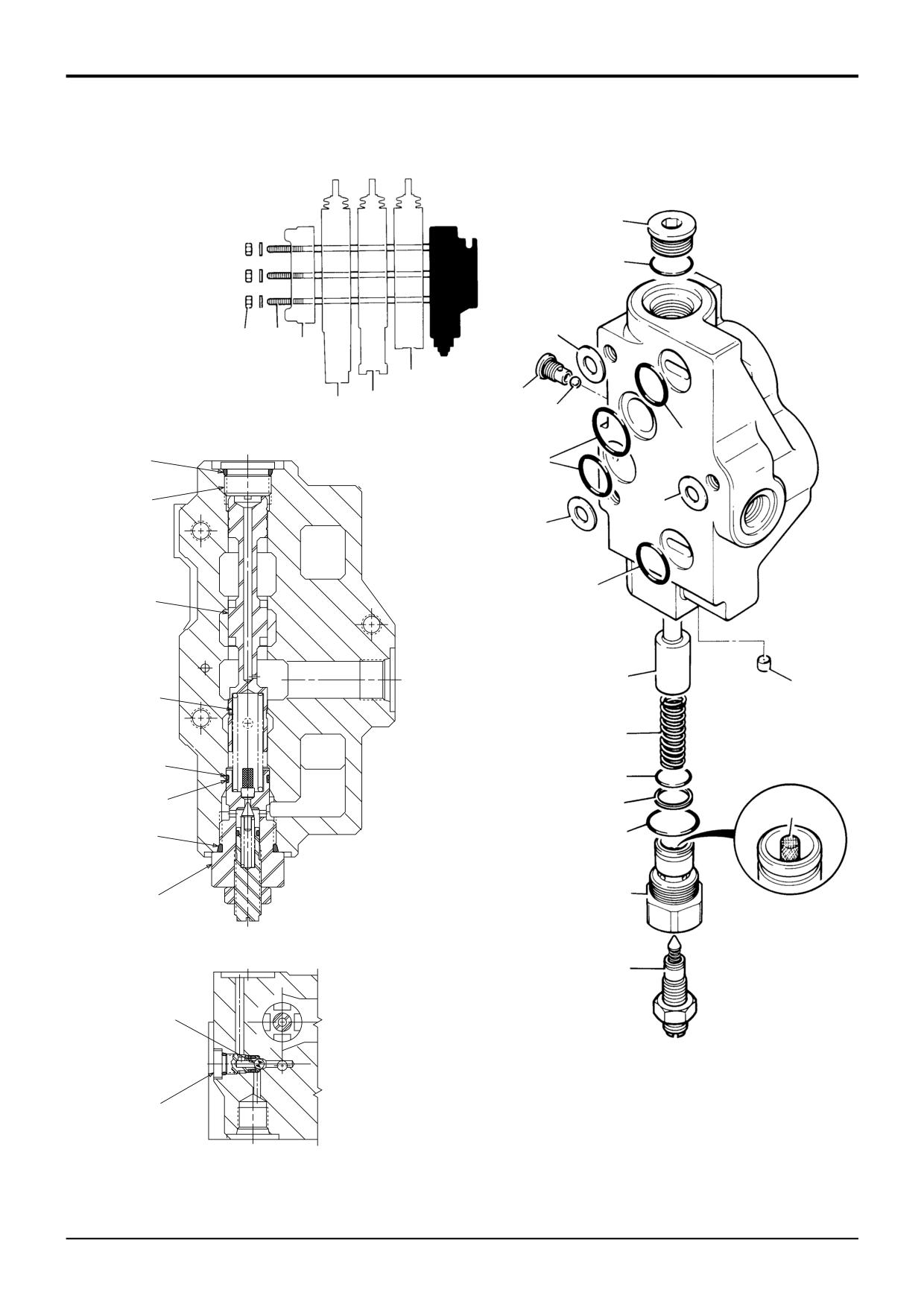
Remove tie rod nuts 1 and end cover 2. Separate the valve
7
67
6.9
50
sections 3 take care not to lose shims 5. Remove and
discard ‘O’ rings 4.
9
67
6.9
50
16
13.5
1.38
10
When removing 'O' rings and seals, use an appropriately
Item
Description
rounded tool that WILL NOT cause any damage to the seal
1
Tie rod nuts
grooves.
2
End cover
3
Valve section
Discard ALL 'O' rings and back up rings. DO NOT use worn
4
O-ring
or damaged items.
5
Shim
6
Tie rod
Inspect the valve components for scratches, nicks or any
other type of damage, replace with new if required.
7
Plug
8
O-ring
9
Relief valve assembly
Inspect screen A, make sure the screen is clean and free of
10
O-ring
dirt.
11
O-ring
Take care not to lose ball bearing 17.
12
Back-up ring
13
Spring
14
Spool
If required, the relief valve assembly 9 can be dismantled for
15
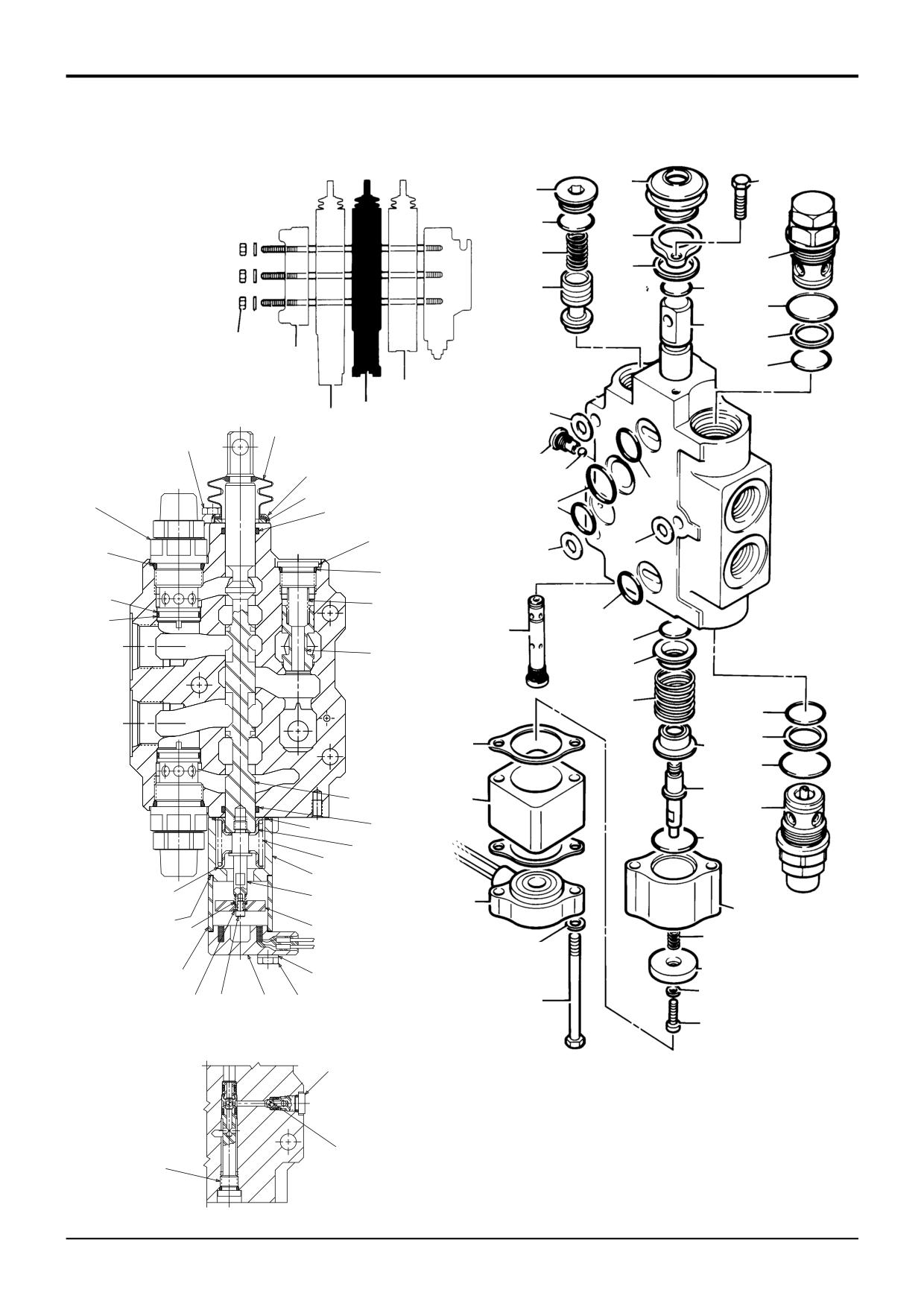
Expansion plug
cleaning. It is important to note that this relief valve is fitted
16
Shuttle plug assembly
as a standard part of the inlet section. However, in this
application it does not perform any duties. This is because
17
Ball bearing
18
Adjusting Screw
the steer system pressure is controlled by a relief valve in
the orbitrol steer unit (see Steering section), NOT relief valve
assembly 9.
After assembling the relief valve, screw the adjusting screw
18 fully into the valve housing. This will ensure assembly 9
does not interfere with the steer system pressure.
9803/3280
Issue 1
Section E
Hydraulics
Section E
55 - 4
Loader Valve - Variable Flow
55 - 4
Dismantling and Assembly
7
21
6
Auxiliary Spool
22
8
23
9
24
20
13
1
2
3
3
5
3
7
6
26
27
8
4
9
4
20
5
21
5
22
23
4
25
19
24
18
17
15
S276070
16
14
19
13
18
16
12
17
11
11
15 14
12
10
10
26
A276080
27
25
9803/3280
Issue 1
Section E
Hydraulics
Section E
55 - 5
Loader Valve - Variable Flow
55 - 5
Dismantling and Assembly
Assembly
Auxiliary Spool
Renew all 'O' rings and back-up rings.
The numerical sequence shown on the illustration is
intended as a guide to dismantling.
When fitting bolt 14, clean the threads then apply a small
quantity of JCB Threadlocker & Sealer to the threads of the
For assembly the sequence should be reversed.
spool.
The following points MUST be avoided when dismantling
When fitting spool seals 19 and 20 refer to the procedure
and assembling the valve:
Fitting Spool Seal.
•
CONTAMINATION
ALWAYS fit three shim (item 5) in between each valve block
•
DAMAGE TO SPOOL
section as shown.
•
DAMAGE TO SEAL GROOVES
Run the engine and inspect the valve for external leaks.
All or any of the above points may result in possible
problems with the valve.
Torque Settings
Dismantling
Item
Nm
kgf m
lbf ft
1
41
4.1
30
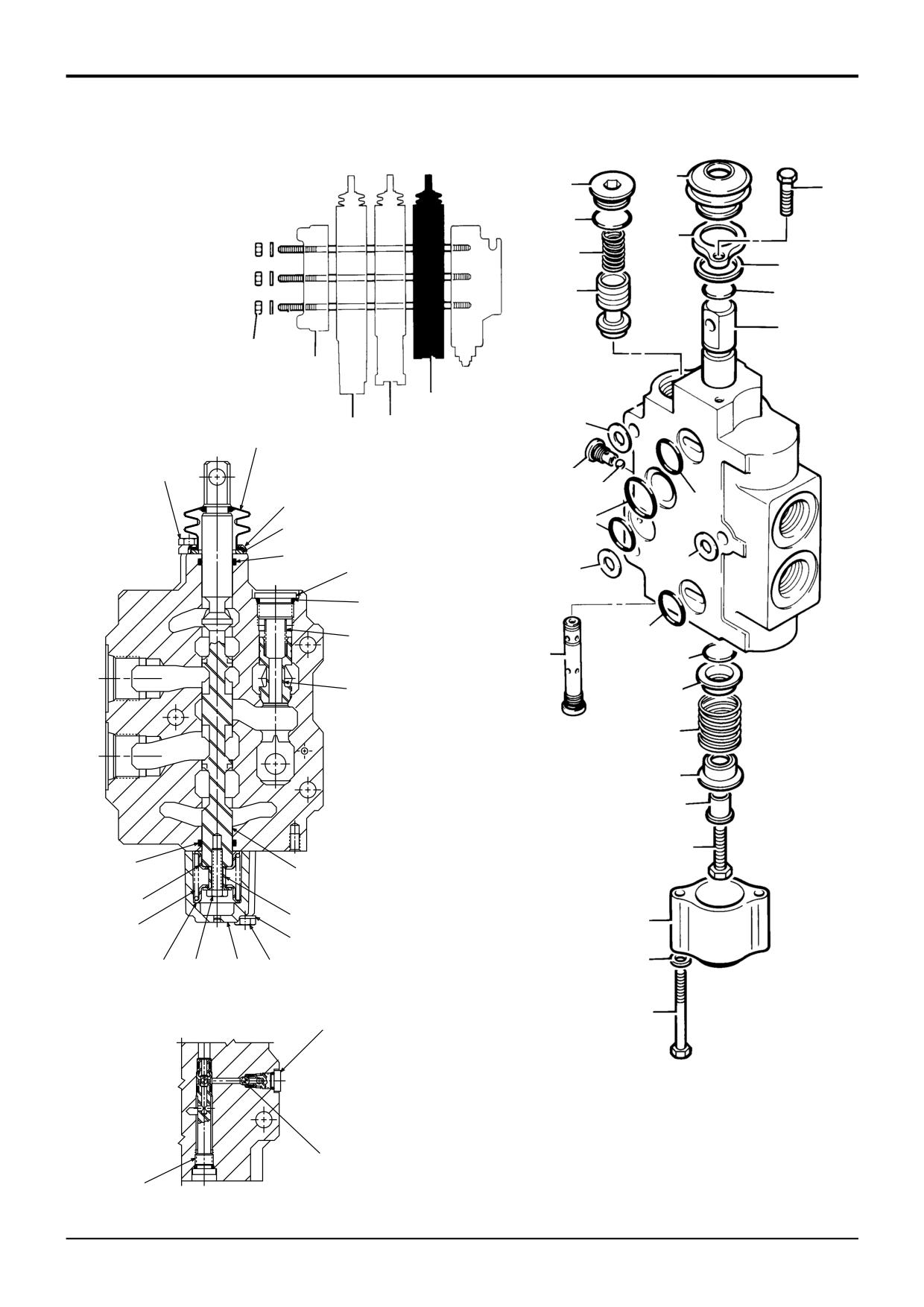
Remove tie rod nuts 1 and end cover 2. Separate the valve
6
6
0.55
4
sections 3 take care not to lose shims 5. Remove and
discard ‘O’ rings 4.
10
8
0.8
6
14
8
0.8
6
21
67
6.9
50
When removing 'O' rings and seals, use an appropriately
25
13.5
1.38
10
rounded tool that WILL NOT cause any damage to the spool
26
13.5
1.38
10
or seal grooves.
Care must be taken to ensure that the spool 13 is not
Item
Description
damaged when removing it from the valve block.
1
Tie rod nuts
2
End cover
Hold the spool in a suitable clamp, unscrew bolt 14 and
remove spring 17, spacer 16 and cups 15 and 18.
3
Valve section
4
O-ring
5
Shim
6
Bolt
7
Dust boot
8
Dust guard
9
Seal
10
Bolt
11
Washer
12
Centering spring housing
13
Spool assembly
14
Bolt
15
Spring cup
16
Spacer
17
Spring
18
Spring cup
19
O-ring
20
O-ring
21
Plug
22
O-ring
23
Spring
24
Poppet
25
Primary shuttle housing
26
Shuttle plug assembly
27
Ball bearing
9803/3280
Issue 1
Section E
Hydraulics
Section E
55 - 6
Loader Valve - Variable Flow
55 - 6
Dismantling and Assembly
7
6
Loader Shovel Spool
26
27
8
28
30
9
29
35
31
21
32
1
2
33
3
3
5
3
7
6
8
37
38
9
4
30
35
4
26
5
31
5
27
32
28
33
4
36
34
29
25
24
33
32
14
23
31
22
21
13
30
34
20
20
25
24
19
23
22
12
14
19
17
18
18
11
11
17
13
16
16
15
12
10
10
15
37
S276140
38
36
A276150
9803/3280
Issue 1
Section E
Hydraulics
Section E
55 - 7
Loader Valve - Variable Flow
55 - 7
Dismantling and Assembly
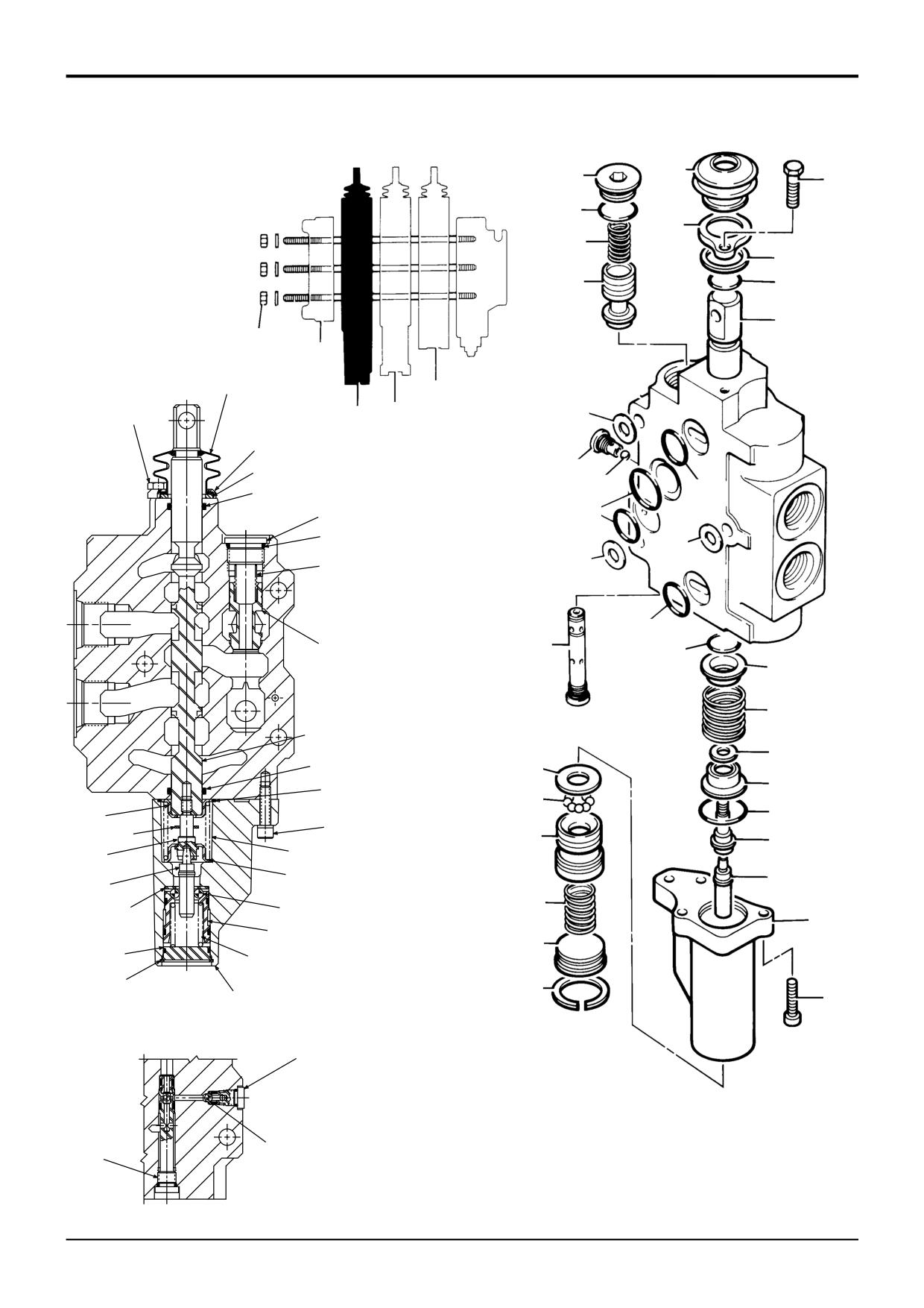
Loader Shovel Spool
Torque Settings
The numerical sequence shown on the illustration is
Item
Nm
kgf m
lbf ft
intended as a guide to dismantling.
1
41
4.1
30
6
6
0.55
4
For assembly the sequence should be reversed.
10
8
0.8
6
15
2.7
0.27
2
The following points MUST be avoided when dismantling
22
11
1.1
8
and assembling the valve:
26, 30
67
6.9
50
•
CONTAMINATION
Item
Description
•
DAMAGE TO SPOOL
1
Tie rod nuts
•
DAMAGE TO SEAL GROOVES
2
End cover
3
Valve section
All or any of the above points may result in possible
4
O-ring
problems with the valve.
5
Shim
6
Bolt
Dismantling
7
Dust boot
8
Dust guard
Remove tie rod nuts 1 and end cover 2. Separate the valve
9
Seal
sections 3 take care not to lose shims 5. Remove and
discard ‘O’ rings 4.
10
Bolt
11
Washer
12
Detent Solenoid
When removing 'O' rings and seals, use an appropriately
13
Tube
rounded tool that WILL NOT cause any damage to the spool
14
Gasket
or seal grooves.
15
Capscrew
16
Washer
Place a suitable rod through the eye end of spool 21.
17
Armature Plate
18
Spring
Care must be taken to ensure that the spool 21 is not
19
Centering Spring Housing
damaged when removing it from the valve block.
20
O-ring
21
Spool
Hold the spool in a suitable clamp, Unscrew coupling 22 and
22
Coupling
remove spring 24 and cups 23 and 25.
23
Spring cup
24
Spring
Relief valve assembly 30 can be dismantled for cleaning
purposes only. Individual parts for the relief valve are not
25
Spring cup
26
Plug
available (except seal kits).
27
O-ring
28
Spring
Assembly
29
Poppet
Renew all 'O' rings and back-up rings.
30
Relief valve assembly
31
O ring
32
Back-up ring
Inspect gasket 14, replace with a new one if required.
33
O-ring
34
O-ring
When fitting coupling 22, clean the threads then apply a
small quantity of JCB Threadlocker & Sealer to the threads
35
O-ring
36
Primary shuttle housing
of the spool.
37
Shuttle plug assembly
38
Ball bearing
Check the operation of the solenoid 12 after assembly by
connecting a 12V supply . The spool should be held when it
is pushed into the detent position and returned when the
supply is disconnected.
When fitting spool seals 34 and 35 refer to the procedure
Fitting Spool Seal.
ALWAYS fit three shim (item 5) in between each valve block
section as shown.
Run the engine and inspect the valve for external leaks.
9803/3280
Issue 1
Section E
Hydraulics
Section E
55 - 8
Loader Valve - Variable Flow
55 - 8
Dismantling and Assembly
7
31
Loader Lift Spool
6
32
8
33
9
34
27
18
1
2
7
3
6
3
3
5
8
9
29
30
27
4
31
4
32
5
33
5
4
34
28
26
24
22
18
23
26
17
25
21
16
24
25
10
23
15
20
22
20
21
19
19
16
14
17
11
15
13
13
14
12
11
12
10
29
A276120
S276110
30
28
9803/3280
Issue 1
Section E
Hydraulics
Section E
55 - 9
Loader Valve - Variable Flow
55 - 9
Dismantling and Assembly
Assembly
Loader Lift Spool
Renew all 'O' rings and back-up rings.
The numerical sequence shown on the illustration is
intended as a guide to dismantling.
When fitting coupling 20, clean the threads then apply a
small quantity of JCB Threadlocker & Sealer to the threads
For assembly the sequence should be reversed.
of the spool.
The following points MUST be avoided when dismantling
When fitting spool seals 26 and 27 refer to the procedure
and assembling the valve:
Fitting Spool Seal.
•
CONTAMINATION
ALWAYS fit three shim (item 5) in between each valve block
•
DAMAGE TO SPOOL
section as shown.
•
DAMAGE TO SEAL GROOVES
Run the engine and inspect the valve for external leaks.
All or any of the above points may result in possible
problems with the valve.
Torque Settings
Dismantling
Item
Nm
kgf m
lbf ft
1
41
4.1
30
Remove tie rod nuts 1 and end cover 2. Separate the valve
6
6
0.55
4
sections 3 take care not to lose shims 5. Remove and
discard ‘O’ rings 4.
10
8
0.8
6
20
8
0.8
6
28
13.5
1.38
10
When removing 'O' rings and seals, use an appropriately
29
13.5
1.38
10
rounded tool that WILL NOT cause any damage to the spool
31
67
6.9
50
or seal grooves.
Item
Description
Care must be taken to ensure that the spool 18 is not
1
Tie rod nuts
damaged when removing it from the valve block.
2
End cover
3
Valve section
Hold the spool in a suitable clamp, use a punch to separate
detent shaft 19 from coupling 20. Unscrew coupling 20 and
4
O-ring
5
Shim
remove spring 22, spacer 23 and cups 21 and 24.
6
Bolt
7
Dust boot
Use a suitable press to compress spring 14 and remove
8
Dust guard
retaining ring 12. Take care not to lose detent balls 16.
9
Seal
10
Capscrew
11
Detent housing
12
Retaining ring
13
Retainer
14
Spring
15
Piston
16
Detent balls
17
Washer
18
Spool assembly
19
Detent shaft
20
Pivot coupling
21
Spring cup
22
Spring
23
Spacer
24
Spring cup
25
O-ring
26
O-ring
27
O-ring
28
Primary shuttle housing
29
Shuttle plug assembly
30
Ball bearing
31
Plug
32
O-ring
33
Spring
34
Poppet
9803/3280
Issue 1
Section E
Hydraulics
Section E
55 - 10
Loader Valve - Variable Flow
55 - 10
Dismantling and Assembly
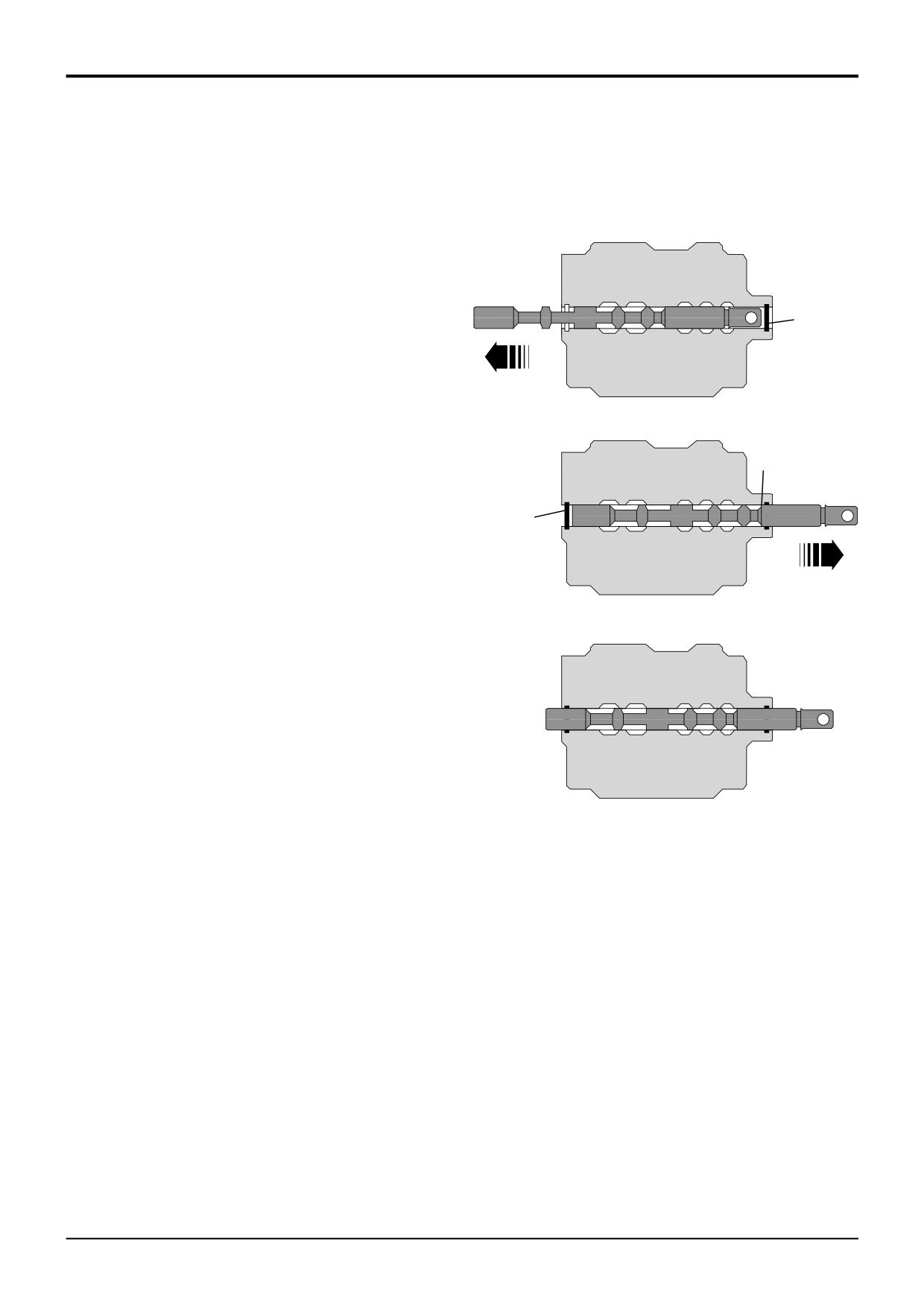
Fitting Spool Seal
Use the procedure described below to correctly install the
valve spool seals:
1
1
Lubricate the spool, bore and O-ring groove with JCB
Hydraulic Fluid. Move the spool to the position shown
A
and then install the O-ring A in its groove.
C
2
2
Move the spool to the position shown and then install
B
the O-ring B. It is important to note that the spool must
not be moved beyond the position shown, otherwise
the edge of the spool (face C) may damage the first
fitted O-ring (item A).
3
3
Position the spool in its central position as shown. Re-
assembe the centering assembly, dust boot etc as
detailed previously in this section.
A276280
9803/3280
Issue 1
Section E
Hydraulics
Section E
60 - 1
Excavator Valve
60 - 1
Removal and Replacement
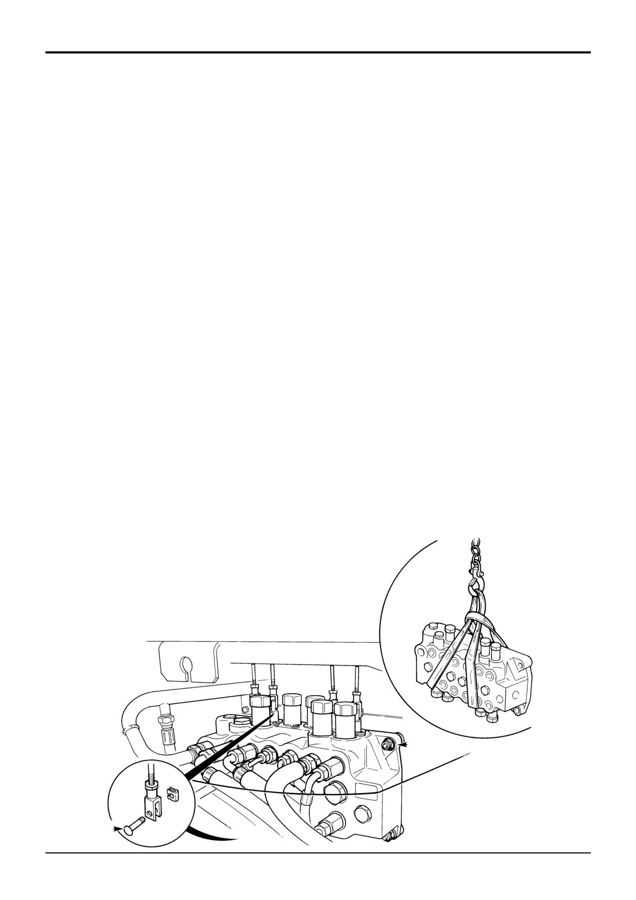
! CAUTION
Manual Control
This component is heavy. Do not attempt to remove it
unless its weight is held by a sling. Make sure that the
! WARNING
sling is attached to a suitable lifting appliance.
Make the machine safe before working underneath it.
HYD 2-3/1
Park the machine on level ground, lower the arms. Apply
the parking brake, put the transmission in neutral and
6
Wrap a suitable sling around the valve, make sure that
stop the engine. Chock both sides of all four wheels.
the weight of the valve is supported by the sling.
Disconnect the battery, to prevent the engine being
7
Remove nuts B and lower the valve block to the
started while you are beneath the machine.
ground.
GEN-1-2
Replacement
! DANGER
Hydraulic fluid at system pressure can injure you. Before
Replacement is a reversal of the removal sequence.
disconnecting or connecting hydraulic hoses, stop the
engine and operate the controls to release pressure
Hoses and pipes (when applicable) must be re-connected
trapped in the hoses. Make sure the engine cannot be
and phased in same position as removal. Refer to
started while the hoses are open.
Dismantling and Assembly, Hoses and Pipes.
INT-3-1-11/1
! WARNING
Removal
Fine jets of hydraulic fluid at high pressure can
penetrate the skin. Do not use your fingers to check for
1
Operate the valve block levers back and forth to vent
hydraulic fluid leaks. Do not put your face close to
residual pressure.
suspected leaks. Hold a piece of cardboard close to
suspected leaks and then inspect the cardboard for
2
Remove the rear valance.
signs of hydraulic fluid. If hydraulic fluid penetrates your
skin, get medical help immediately.
3
Remove clevis pins A to disconnect the control levers
INT-3-1-10/1
from the valve block spools.
After replacement check the auxiliary relief valve (A.R.V.)
4
Disconnect all hydraulic hoses from the valve block and
pressure settings.
plug all orifices to prevent ingress of dirt. Label each
hose before disconnecting, this will ensure correct
Note: All hydraulic adapters that are installed together with
position when refitting.
a bonded sealing washer must also have JCB Threadseal
applied to the threads of the adapter.
5
Loosen nuts B - do not completely remove the retaining
nuts.
B
A
S401480
9803/3280
Issue 1