JCB 3CX, 4CX, 214e, 214, 215, 217 & VARIANTS Backhoe Loader. Service Manual - page 17
Section E
Hydraulics
Section E
24 - 2
Service Procedures
24 - 2
B
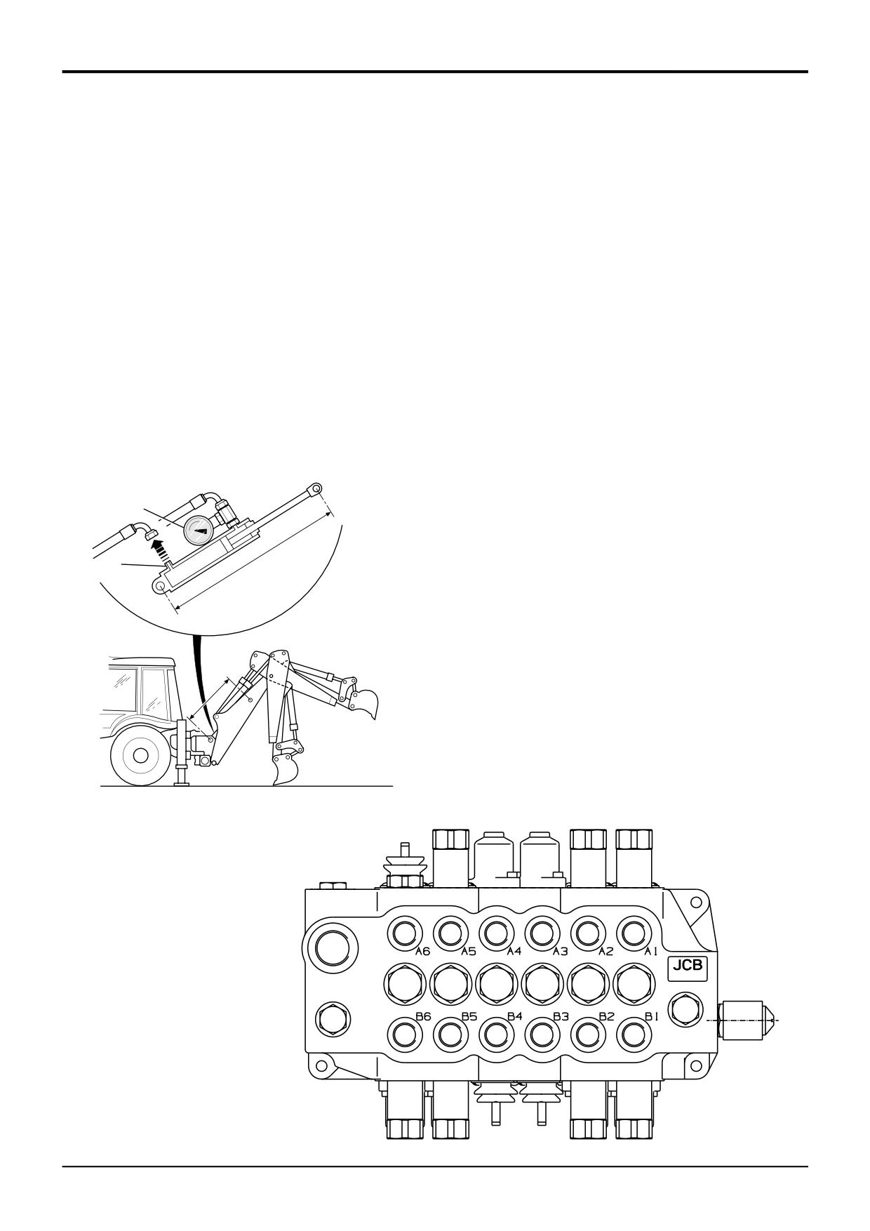
Test Cylinder/Piston Leakage
C Test Spool Leakage
1
Ensure that the oil temperature is at 50°C (122°F) by
Note: The following procedure applies only to services fitted
using the hydraulic oil temperature probe detailed in A1.
with A.R.V.'s. Note A.R.V.'s are not fitted to loader lift,
loader auxiliary, stabilisers or to the bucket rod side service
2
Take the weight off the ram to be tested, in this example,
except when a Rockbreaker is fitted.
by positioning the backhoe with dipper vertical and
bucket on the ground.
1
Render the A.R.V.'s inoperative in the suspect service.
3
Use a suitable pressure gauge A to blank off the
This is achieved by removing the A.R.V. and replacing
supporting port of the ram.
with a blanking plug (part no. 25/609901) and seal kit
(25/610301).
4
Disconnect the hose from the opposite port D and leave
the port open to atmosphere.
2
Re-check the piston rod movement as described steps
A1 to A6.
5
Apply a load to the suspect ram for example the boom
ram by raising the dipper to the horizontal as at B.
A.R.V.
Control Layout
6
After the initial movement measure the pin to pin
JCB ISO
movement as at C and note the rod movement over 10
minutes.
Slew
7
If rod movement is evident the ram is defective.
- Right
B1
B1
- Left
A1
A1
Boom
- Rod
B2
B5
- Head
A2
A5
A
Dipper
- Rod
A5
A2
- Head
B5
B2
Bucket
D
C
- Rod
A6
A6
- Head
B6
B6
Note: Bucket ram rod side ARV only fitted to machines
equipped with Rockbreakers.
B
3
If the rod movement is now acceptable the A.R.V. must
C
be at fault. The A.R.V. may only require cleaning and
then resealing. If dirt is evident, the hydraulic tank should
be drained and cleaned. It is recommended that when
re-filling the hydraulic tank that new oil and filter be used
to prevent further contamination. If the A.R.V. is worn it
should be replaced.
FIG 2
380200
380201
A401470
9803/3280
Issue 1
Section E
Hydraulics
Section E
24 - 3
Service Procedures
24 - 3
Table 1
Ram
Cylinder
Rod
Total Displacement - mm/10 minutes @
Dia. (mm)
Dia. (mm)
69 bar
138 bar
207 bar
(1000 lb/in2)
(2000 lb/in2)
(3000 lb/in2)
HEAD SIDE
Backhoe
S/shift Jack Leg
70
40
13
44
91
Knuckle
100
60
6
16
32
Ext Dip
70
40
13
32
65
Loader
Clam
70
40
6
22
45
Lift
80
50
5
17
35
Lift
90
50
4
13
28
ROD SIDE
Backhoe
Boom
110
60
8
26
52
Boom
120
65
6
22
44
Boom
130
70
5
19
37
Boom
140
75
5
16
32
Bucket
90
50
11
45
114
Bucket
100
60
10
40
99
Dipper
100
60
10
34
70
Dipper
110
65
8
28
57
Ext Dip
70
40
19
66
96
Loader
Shovel
70
40
10
33
68
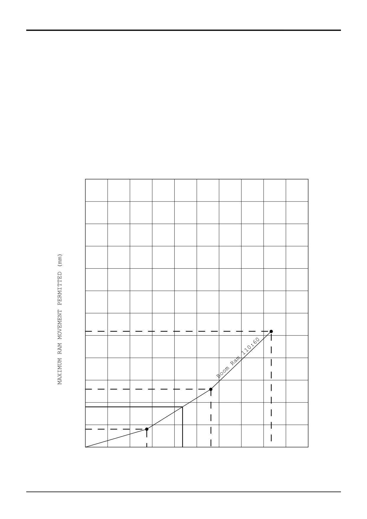
Using the figures above, a graph can be plotted and the maximum amount of movement determined. See the next page for a
working example.
9803/3280
Issue 1
Section E
Hydraulics
Section E
24 - 4
Service Procedures
24 - 4
EXAMPLE - Boom Ram110 x 60
1
Using the figures given in the table on page 3, plot a
graph for the ram to be tested.
2
Check the pressure in the ram (induced by the applied
load). In this example the pressure on the gauge reads
107 bar; 1500 lb/in2.
3
Draw a vertical line from the pressure reading to the
plotted graph line. Where the vertical line intercepts the
graph line, draw a horizontal line and read the permitted
ram displacement. In this example the permitted
maximum displacement is 18 mm.
Note: A blank graph is provided on the next page,
photocopy and use as required.
120
100
80
60
52mm
40
26mm
20
18mm
8mm
0
50
100
150
200
250
69bar
107bar
138bar
207bar
PRESSURE (BAR)
380210
9803/3280
Issue 1

Section E
Hydraulics
Section E
24 - 5
Service Procedures
24 - 5
120
100
80
60
40
20
0
50
100
150
200
250
PRESSURE (BAR)
380220
9803/3280
Issue 1
Section E
Hydraulics
Section E
25 - 1
Service Procedures
25 - 1
Quick Release Couplings
- Connecting and Disconnecting
! WARNING
Flat face quick release couplings allow the operator to
Hydraulic fluid at pressure can injure you. Make the
remove and install attachments swiftly and efficiently.
machine safe before connecting or disconnecting quick
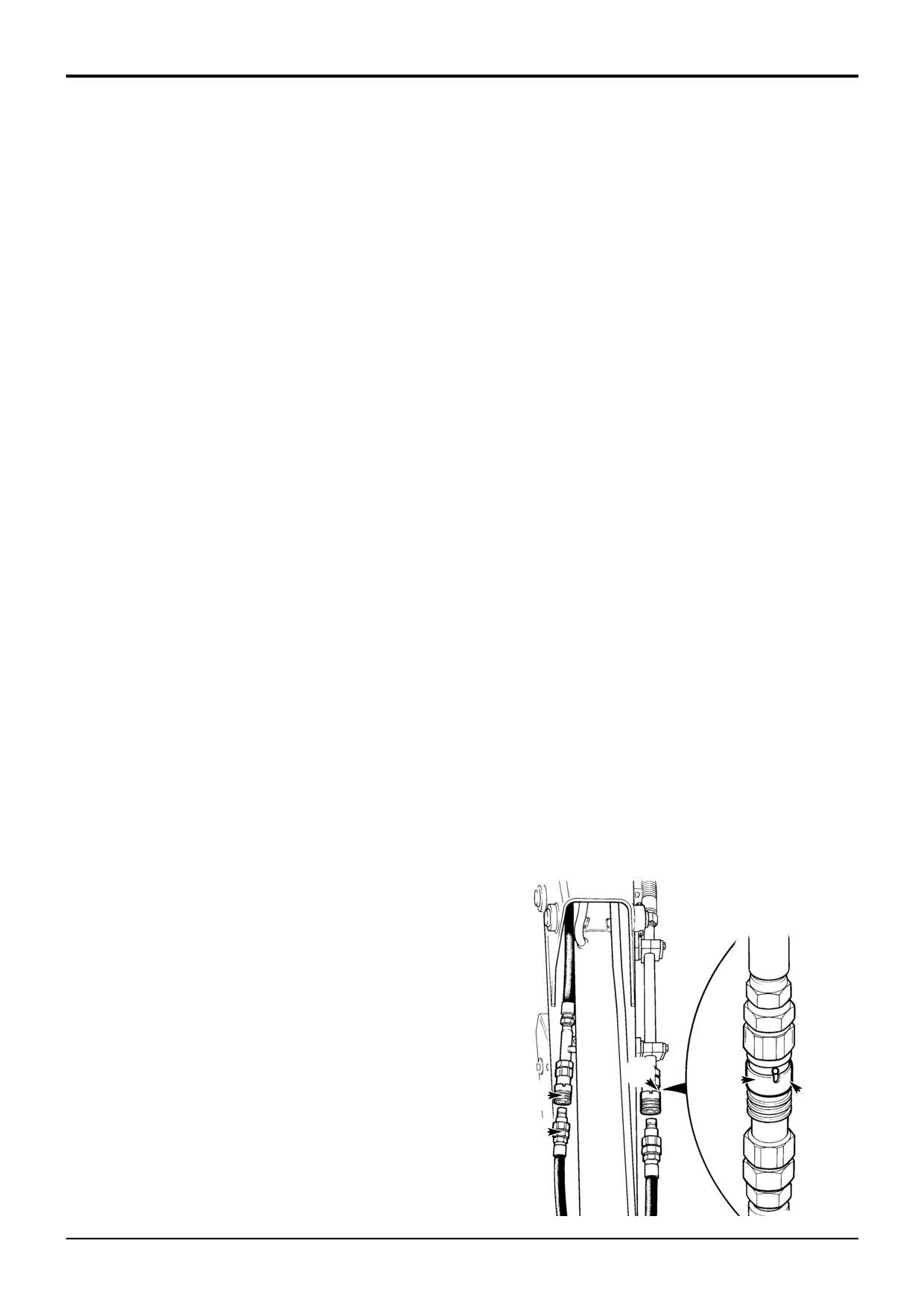
Generally, your machine pipework will have female couplings
release couplings; stop the engine and then operate the
A fitted, and the optional attachment hoses will have male
attachment control a few times to vent residual hydraulic
couplings B fitted.
pressure in the attachment hoses.
2-4-1-11
The quick release couplings should be trouble free and
relatively easy to connect and disconnect, provided they are
Before connecting or removing any hydraulic hose, residual
kept clean and used correctly. The recommendations listed
hydraulic pressure trapped in the service hose line must be
below should always apply when using flat face quick
vented. This is usually achieved by switching off the engine
release couplings.
and then operating the attachment control lever several
times. Make sure the hose service line has been vented
Finally, please read the correct fitting and releasing
before connecting or removing hoses - refer to the
procedures before installing or removing any optional
appropriate attachment information in this section.
attachment fitted with quick release couplings.
Quick Release Couplings - Do's & Don'ts
Connecting Quick Release Couplings
1
Remove any residual hydraulic pressure trapped in the
DO wipe the two faces of the coupling and make sure they
service line hose.
are clean before connecting.
2
Wipe the two faces of the male and female couplings
DO make sure the outside sleeve (female coupling) is pulled
and make sure they are clean.
back when disconnecting.
3
Make sure that ball C in the female coupling is located
in one of its slots.
DO connect and disconnect a new coupling two or three
times to 'work' the PTFE seals - sometimes a new coupling
4
Fit the male coupling into the female coupling; To
will stick if the seals have not been 'worked'.
ensure that the coupling is not accidentally released,
rotate sleeve E half a turn and make sure that the
DO use a spanner on the hexagon flats of the coupling when
locking ball C does not align with the slot D.
fitting adaptors.
DO use a rubber or hide hammer to disconnect a coupling if
Disconnecting Quick Release Couplings
it sticks - sticking may occur if there is dirt present in the
coupling.
1
Remove any residual hydraulic pressure trapped in the
service line hose.
DON'T attempt to re-connect a damaged half coupling - this
2
Align the slot D with ball C.
will destroy the seals and necessitate replacing both half
couplings.
3
Pull back sleeve E to release the coupling.
DON'T leave the coupling where it may be run over by a
machine or otherwise crushed - this will distort the coupling
sleeve and prevent correct connection and disconnection.
DON'T clamp on the smooth diameter of the coupling when
fitting adaptors - always use the hexagon.
DON'T try to turn the sleeve (female coupling) when the
coupling has been disconnected - the locking ball will wedge
underneath the sleeve and destroy the coupling.
DON'T damage the faces of the couplings - this can prevent
connection and disconnection, or damage seals and cause
leakage.
C
E
A
D
DON'T try to dismantle the couplings - they are non
serviceable parts. If a coupling is damaged it should be
B
replaced with a new one.
S169490
9803/3280
Issue 1

Section E
Hydraulics
Section E
26 - 1
Service Procedures
26 - 1
Smooth Ride System
Charging/Discharging the Accumulator
Discharging
Charging
1
Park the machine on level ground, lower the loader
1
Park the machine on level ground, lower the loader
arms, switch off the engine and chock all four wheels.
arms, switch off the engine and chock all four wheels.
Release all hydraulic pressure in the accumulator by
Release all hydraulic pressure in the accumulator by
selecting the starter key to the ON position without the
selecting the starter key to the ON position without the
engine running, SRS ON and operating the loader arm
engine running, SRS ON and operating the loader arm
hydraulic lever.
hydraulic lever.
2
Remove gas valve guard A and gas valve cap B.
2
Remove gas valve guard A and gas valve cap B.
3
Screw T handle C all the way out (counter clockwise)
3
Screw T handle C all the way out (counter clockwise)
before attaching charging tool (service tool 892/00948)
before attaching charging tool (service tool 892/00948)
to accumulator gas valve.
to accumulator gas valve.
4
Close bleed valve D.
4
Close bleed valve D.
5
Either connect charging tool to a bottle of compressed
5
Making sure not to loop or twist the hose, connect the
nitrogen gas which is turned off or remove hose F and
charging tool to the gas valve. Tighten to 1.0 lbf ft (1.36
fit a suitable blank on charging tool.
Nm, 0.14 kgf m).
6
Screw T handle C all the way in (clockwise), this will
6
Connect charging tool to a bottle of compressed
depress the core in the gas valve.
nitrogen gas.
7
Open bleed valve D until all the gas charge is relieved
7
Screw T handle C all the way in (clockwise), this will
from the accumulator. Remove the charging tool.
depress the core in the gas valve. Check charge
pressure which should be set to suit the loader and the
attachment fitted to the machine. For recommended
charge pressures refer to Technical Data - Smooth
Ride System.
8
If charge pressure is low, carefully open hand valve E
on the nitrogen bottle and SLOWLY fill the accumulator.
Close valve E when the required charge pressure is
reached on the gauge.
9
Let the pressure settle for 10 to 15 minutes. This will
allow the gas temperature to stabilise. If the charge
pressure is exceeded, with the gas bottle closed, open
bleed valve D. Reduce pressure as required, then close
bleed valve.
! CAUTION
To reduce pressure use the recommended charging tool
A
or the charge valve could be damaged which may result
in rapid discharge of the accumulator.
B
HYD 2-4
10
When complete screw T handle C all the way out
(counter clockwise) then open the bled valve D to vent
the hose.
D
E
F
11
Hold the gas valve to keep from turning, loosen nut and
remove charging tool.
C
12
Refit gas valve cap and valve guard.
S308270
9803/3280
Issue 1
Section E
Hydraulics
Section E
27 - 1
Service Procedures
27 - 1
Hose Burst Protection Valves
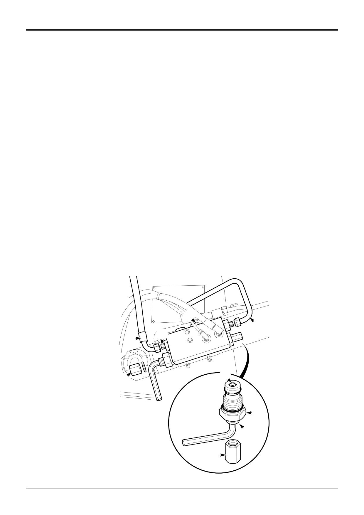
The hose burst protection valves (if fitted) prevent the loader
or backhoe falling in the event of a hose burst. These valves
may be fitted on rams which raise or lower the loader arms,
the boom or the dipper.
Lowering a Load - In a Failure Condition
Checking
During normal operation, the engine must be running before
1
Raise the loader arms fully. Raise the boom to about
a load can be lowered. The following paragraphs describe
45°. Raise the dipper to the horizontal.
how to safely and correctly lower a load in the event of
engine failure or a hose burst; we recommend that only a
2
Stop the engine
competent maintenance engineer perform the procedures.
3
Using the control levers, try to lower the loader, boom
After lowering a load do not use the machine until the
and dipper. Push the levers fully to the 'lower' position.
manual over-ride screw has been reset (Loader HBPV, refer
If there is any movement, adjust or replace the hose
to Pressure Testing - Loader Lift Ram) or a new end cap
burst protection valve as applicable.
and valve assembly fitted (Boom HBPV, refer to Hose Burst
Protection Valves - Dismantling and Assembly), otherwise
the valve will not operate as intended.
S320930
! DANGER
Do not stand underneath the raised load during the
lowering procedure. Stand clear and to one side until the
A
load has been safely lowered. Make sure that the area is
clear of other people before lowering the load. If you do
not follow these precautions you or others could be
C
killed or seriously injured.
2-3-5-3
D
Boom and Dipper Hose Burst Protection Valve (HBPV)
1
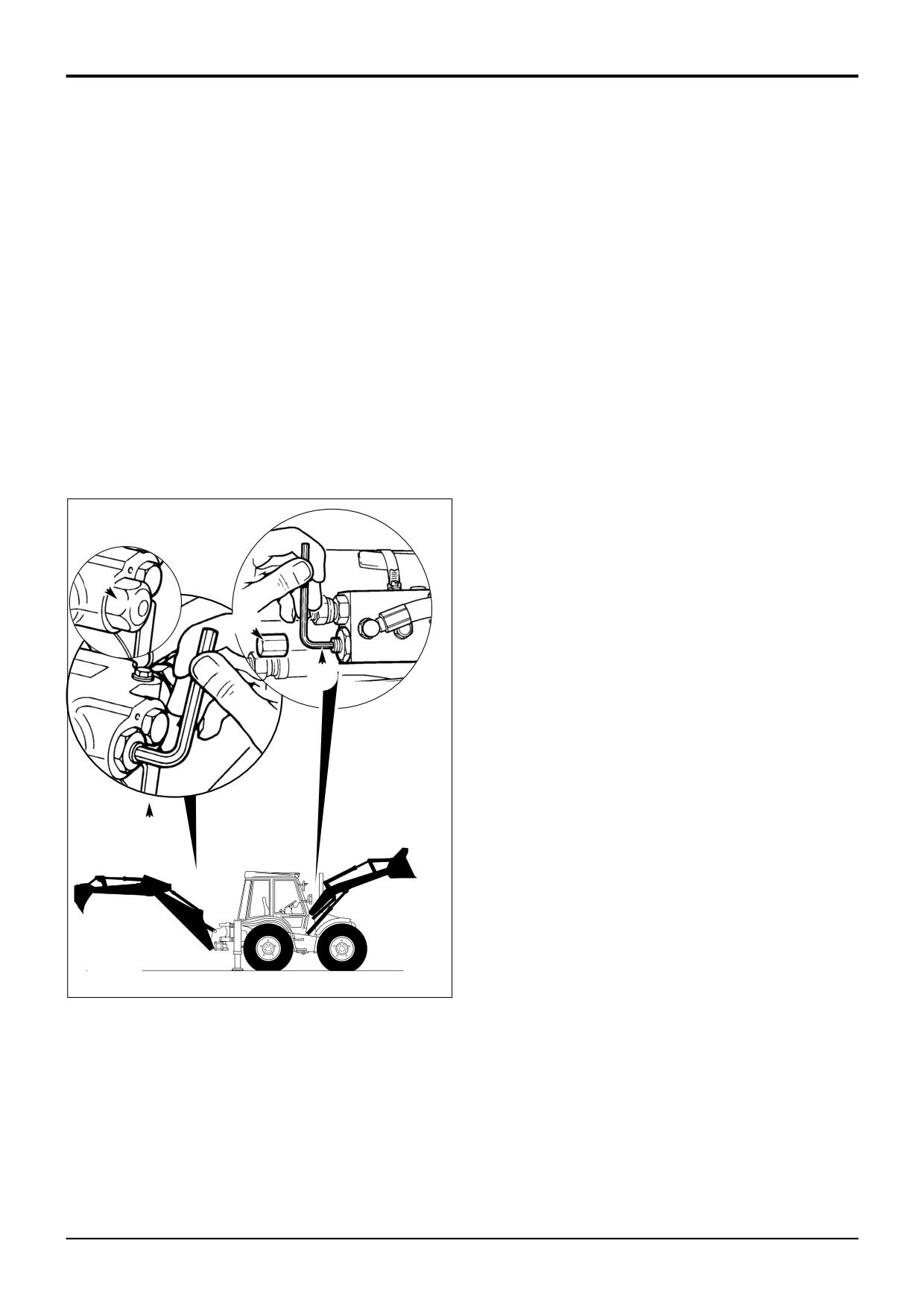
Remove cap A and pierce the warning label.
S170582
2
If a hose has burst, position a suitable container to
catch the oil.
3
Insert an 6mm allen key into the socket head of screw
B. Slowly turn the allen key in a clockwise direction until
the load just begins move.
Burst hose - Lower the boom using screw B, turn the
B
screw counter-clockwise to slow or stop the load from
lowering.
Dead engine - Operate the control lever in the cab to
lower the load.
Loader Hose Burst Protection Valve (HBPV)
1
Remove cap C from both HCPV check valves on the
A171340
A171340
loader lift arms.
2
If a hose has burst, position a suitable container to
catch the oil.
3
On the burst hose HBPV, insert an 5mm allen key into
the socket head of screw D. Turn the allen key in a
clockwise direction so that the screw winds fully in.
Repeat slowly for the opposite side as the load is now
supported on this HBPV.
Note: Count the number of full turns on each screw for
resetting purposes.
4
Operate the control lever in the cab to lower the load.
9803/3280
Issue 1
Section E
Hydraulics
Section E
27 - 2
Service Procedures
27 - 2
Hose Burst Protection Valves
Pressure Testing - Loader Lift Ram
The following text describes the pilot valve setting
procedures and pressure testing sequences for ONE HBPV
only, repeat the procedures for BOTH loader arm lift rams.
Preparation
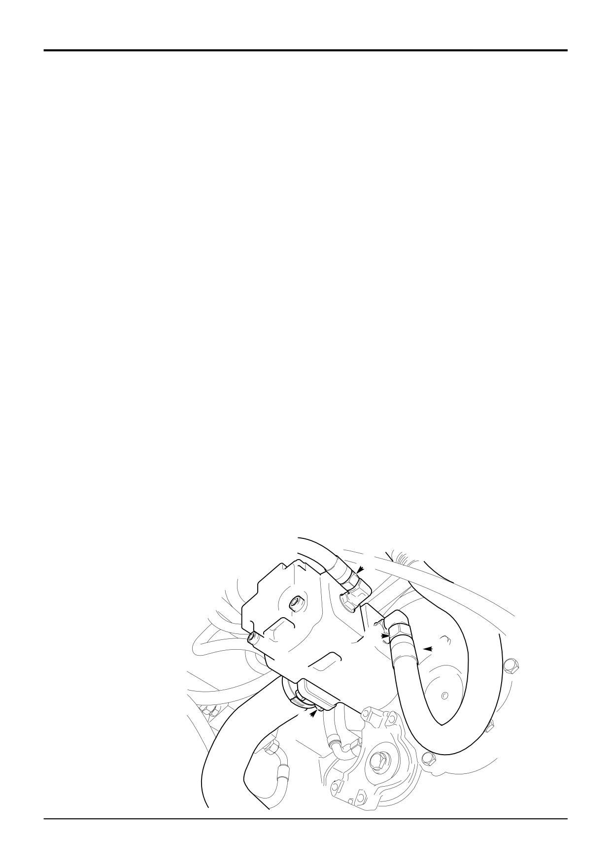
Pilot Valve Setting Procedure
Before starting the pressure testing procedure vent hydraulic
The pilot valve assembly, shown at C, must be set correctly
system pressure as follows:
before doing the relief valve pressure test. If the pilot valve
is screwed too far into the HBPV it will create a flow path
1
Park the machine on firm level ground, engage the
connection from port C2 to port V2 (see descriptions of
parking brake and set the transmission to neutral.
operation).
2
Lower the loader arms to the ground (not lifting the
To set the pilot valve assembly:
machine).
1
Remove pilot housing, item D, from the HBPV.
3
Select 'ARMS LOWER' to raise the front wheels
approximately 25 - 50 mm (1 - 2 in) off the ground.
2
Check that the end face of the pilot valve assembly,
item C, is flush (level) with the end face of its housing
4
Switch off the engine.
D, as shown at E.
5
Make sure all personnel are clear of the machine before
3
If necessary, remove end cap F and, using a suitable
completing step 6.
Allen key, adjust the pilot valve as required.
6
Select 'ARMS RAISE' - this will vent residual hydraulic
4
Refit the end cap.
pressure from the loader rams (head side).
Continured
7
Move all the backhoe control levers back and forth to
vent any other residual hydraulic pressure from the
backhoe service hoses.
A
G
K
J
E
B
D
C
F
327330
9803/3280
Issue 1
Section E
Hydraulics
Section E
27 - 3
Service Procedures
27 - 3
Hose Burst Protection Valves
Pressure Testing - Loader Lift Ram
(continued)
Relief Valve Pressure Test
If the hose burst protection valve has been stripped and
cleaned, then pre-set the valve as detailed in step 1. The
pressure test procedure is described in steps 2 to 6.
1
Pre-set the relief valve:
a Remove cap B and its copper washer. Using an
Allen key, turn the adjusting screw anti-clockwise
to remove all tension.
b Using your fingers, turn the adjusting screw
clockwise until a soft force (resistance) is felt.
c Using an Allen key, turn the adjusting screw a
further 21/4 turns to pre-set the relief valve. Refit
the cap and washer.
2
Remove hose G from port C2. Cap and plug the hose
and valve port adapter (the valve port adapter MUST be
plugged, otherwise the test procedure will not work).
3
Remove hose J from port V2. Plug the hose but DO
NOT cap the valve port adapter.
4
Remove plug A and in its place fit a 0-400 bar (0-6000
lbf/in2) pressure gauge connected to a hand pump.
5
Use the hand pump to increase the pressure. When the
pressure reaches the setting of the relief valve, oil will
escape from port V2, shown at K. Note the maximum
gauge reading (the setting of the hose burst relief valve)
which should be 250 bar (3625 lbf/in2).
6
If necessary, adjust the pressure setting as follows:
a Remove cap B and its copper washer.
b Using an Allen key, turn the adjusting screw
clockwise to increase the pressure or anti-
clockwise to decrease the pressure. For
information; one full turn of the relief valve adjusting
screw is equivalent to approximately 110 bar (1595
lbf/in2).
c Replace the cap and washer.
d Repeat pressure test, adjust as necessary.
9803/3280
Issue 1
Section E
Hydraulics
Section E
30 - 1
Main Pump
30 - 1
Fixed Flow
Replacement
Replacement is the reverse of the removal procedure.
Removal and Replacement
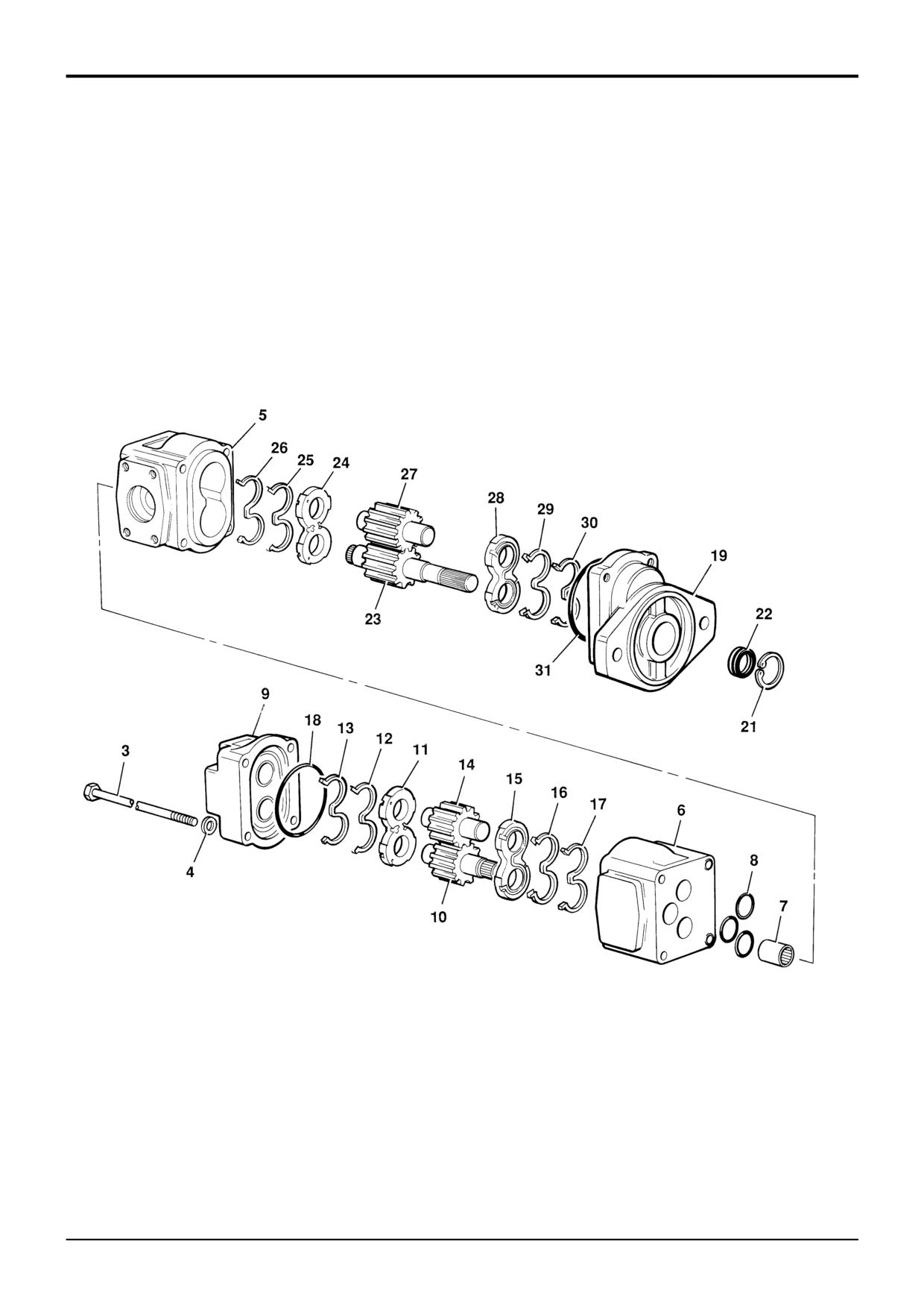
1
Clean off all traces of gasket compound from the pump
The following Procedure describes removal and replacement
and gearbox mounting faces. Apply a thin bead of JCB
of a double section pump, follow the same procedure for
Multigasket to the gearbox mounting face.
single section pumps.
2
Locate the splined shaft of the pump into the gearbox.
Removal
Apply JCB Threadlocker and Sealer to bolts E and
secure the pump flange to the gearbox mounting face.
! WARNING
3
Reconnect the pump outlet hoses C and D to the
Make the machine safe before getting beneath it. Ensure
elbow fittings.
that any fitments on the machine are secure; engage the
parking brake, remove the starter key, disconnect the
Note: All hydraulic adapters that are installed together with
battery.
a bonded sealing washer must also have sealant JCB
INT-3-3-8
Threadseal applied to the threads of the adapter.
1
Remove the propshaft, refer to Section F Propshafts -
4
Reconnect the pump inlet hose flange to the pump
Removal and Replacement.
body with bolts B (4 off).
2
Drain the hydraulic fluid from the hydraulic tank.
5
Fit the propshaft, refer to Section F Propshafts -
Removal and Replacement.
3
Remove flange bolts B (4 off) and disconnect the pump
inlet hose flange from the pump body. Blank off all
6
Fill the system to the correct level with recommended
exposed connections to prevent ingress of dirt.
hydraulic fluid, refer to Section 3 Fluids, Lubricants,
Capacities and Specifications.
4
Disconnect the pump outlet hoses C and D from the
elbow fittings. Blank off all exposed connections to
Note: Replace the suction strainer and return line filter after
prevent ingress of dirt.
fitting a new or serviced pump.
! CAUTION
7
After fitting a new or serviced pump and before starting
The hydraulic pump is heavy. Do not attempt to remove
the engine screw the main relief valve out. Run the
the pump unless its weight is held by a sling. Make sure
engine and check for leaks, also check the main relief
that the sling is attached to a suitable lifting appliance.
valve (M.R.V.) operating pressure. Refer to Section E
HYD 2-3
Service Procedures, Pressure Testing - MRV.
5
Secure the pump using a sling around the pump body,
remove the pump mounting bolts E and carefully
withdraw the pump clear of the gearbox.
Torque Settings
C
Item
Nm
kgf m
lbf ft
B
TBA
E
TBA
D
E
B
A396190
9803/3280
Issue 1
Section E
Hydraulics
Section E
31 - 1
Main Pump
31 - 1
S401450
9803/3280
Issue 1
Section E
Hydraulics
Section E
31 - 2
Main Pump
31 - 2
Fixed Flow
Dismantling and Assembly
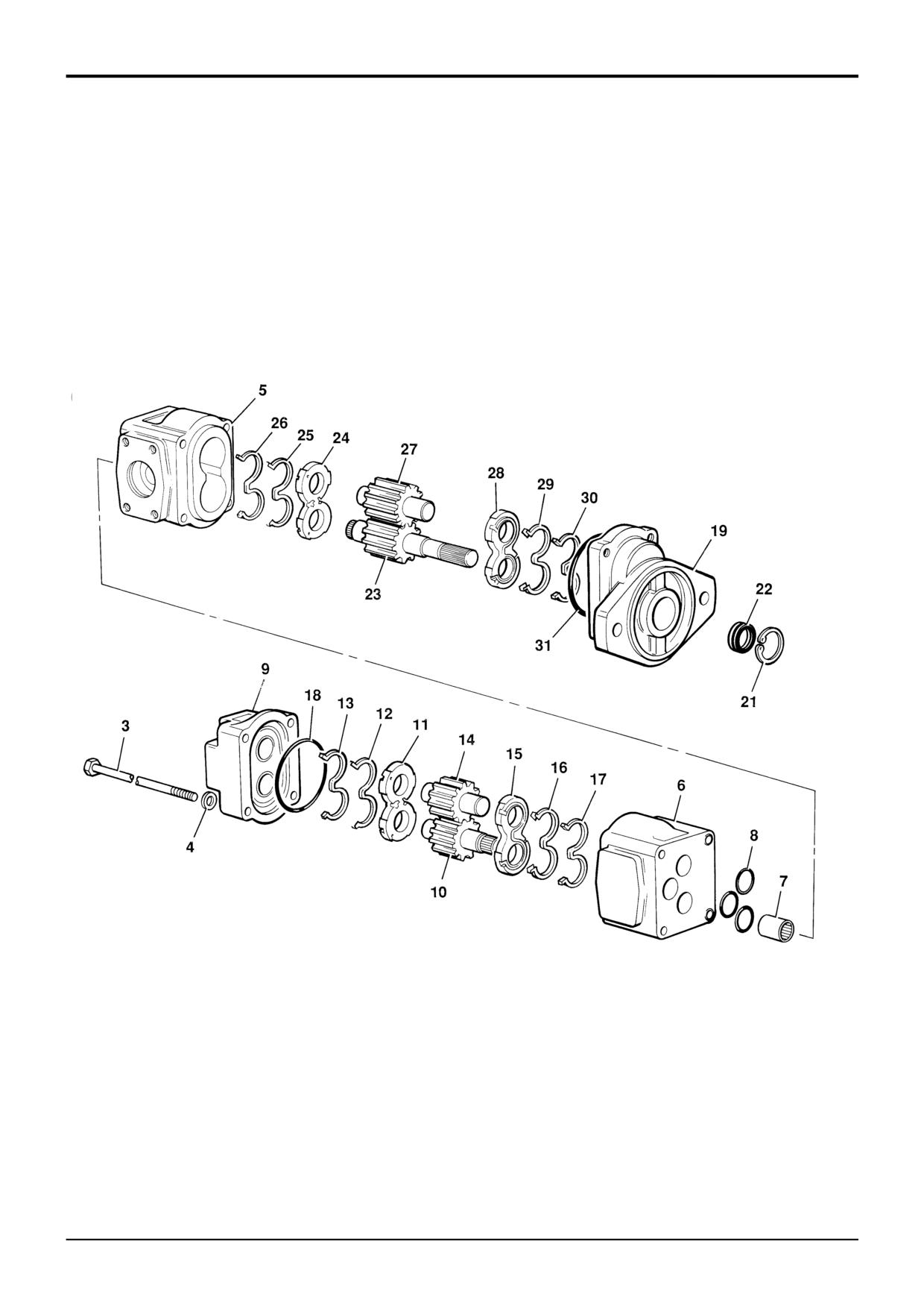
12
Discard O-ring 31.
Before removing and dismantling the pump, check flow and
pressure. If either of these are low the pump must be
13
Remove all sealant from the contact faces of the
changed. Renewal of components such as gears, bearings
mounting flange/front body and end cover/rear body
and housing will not effect a permanent cure. If the pump
interfaces.
output is satisfactory but there is external leakage, the pump
should be removed and dismantled for re-sealing only.
14
Wash all components and immediately apply a coating
of hydraulic oil to prevent corrosion.
Before removing and dismantling the pump, make sure the
exterior of the pump and working area is thoroughly cleaned
Inspection
and free of possible sources of contamination.
1
Generally check all pump parts for damage and/or
Dismantling
wear. The O-ring grooves, the seal recess in the
mounting flange and all sealing faces must be free of
1
Remove the four bolts 3 and serrated washers 4 which
burrs and scores which could result in seal damage
clamp the units together.
and hence hydraulic oil leakage.
2
Use a soft faced hammer to separate front body 5 and
2
Renew the pump if any of the following symptoms
rear body 6 after first marking them to ensure correct
exist:
re-assembly.
a
The PTFE coated bearings in the pump bodies, the
3
Remove splined coupling 7 and O-rings 8. Discard the
mounting flange and the end cover are worn
O-rings.
through to reveal the bronze backing.
4
Use a soft faced hammer to separate end cover 9 from
b
The gear side faces are scored. Often
rear body 6, after first marking them to ensure correct
contaminated fluid results in a distinct wear step
re-assembly.
coincident with the gear root diameter. This can
normally be felt by drawing a sharp point across
5
Remove drive gear 10 from its bore. Pushing it out of
the gear side face from the journal towards the tip
the rear body will also remove balance plate 11
of the gear.
complete with seal 12 and seal energiser 13. Discard
the seal and seal energiser. Note the position of the
c
There is a noticeable wear groove on driveshaft 23
driveshaft and the balance plate to ensure correct re-
where seals 22 run.
assembly.
d
The balance plate faces are scored, particularly in
6
Remove driven gear 14, followed by balance plate 15
the area adjacent to the gear root diameter.
complete with seal 16 and seal energiser 17. Discard
the seal and seal energiser.
e
The shaft splines are worn or severely fretted.
7
Discard O-ring 18.
f
The gear "cut-in" area in the low pressure side of
the pump body is deeper than 0.15 mm (0.006 in)
8
Use a soft hammer to separate mounting flange 19 from
or has a torn or pitted appearance.
front body 5, after first marking them to ensure correct
re-assembly.
9
Remove circlip 21 and shaft seals 22. Note which way
round the seal lips are fitted to ensure correct fitting of
new seals on re-assembly.
10
Remove driveshaft 23 from front body 5. Removal will
also remove balance plate 28 complete with seal 29 and
seal energiser 30. Discard the seal and seal energiser.
11
Remove driven gear 27 followed by balance plate 24,
seal 25 and seal energiser 26. Discard the seal and seal
energiser.
9803/3280
Issue 1
Section E
Hydraulics
Section E
31 - 3
Main Pump
31 - 3
S401450
9803/3280
Issue 1
Section E
Hydraulics
Section E
31 - 4
Main Pump
31 - 4
Fixed Flow
Dismantling and Assembly (continued)
13
Fit balance plate 11 in its original position (i.e. with the
Assembling
two small holes to the low pressure side). Fit seal 12
and seal energiser 13 into the balance plate.
When carrying out the following procedure, renew all seals
and O-rings. Lubricate using JCB Special Hydraulic Fluid.
14
Fit O-ring 18 into end cover 9.
1
Fit shaft seals 22 into mounting flange 19, making sure
15
Apply a small amount of JCB Multigasket to the
the seal lips are the correct way round as noted in
exposed face of rear body 6 (i.e. the face containing
dismantling. Fit circlip 21 into its groove in the flange.
the clamping bolt holes).
Coat the seal lips with high melting point grease.
16
Fit end cover 9 in its original position, as marked
Note: If the seal recess is scored, it is permissible to seal
earlier.
outside diameter with JCB Multigasket to prevent leakage.
17
Install the four bolts 3, each with a serrated washer 4,
2
Stand front body 5 on its rear face. Fit seal 25 and seal
and tighten evenly and progressively to a torque of 90 -
energiser 26 into balance plate 24.
100 Nm (66 - 74 lbf ft).
3
Ensuring that the seals do not fall out, carefully feed the
18
Pour a small amount of clean JCB Special Hydraulic
balance plate into the bores of the front body 5 with the
Fluid into the ports. Check that driveshaft 23 rotates
two small holes through the balance plate to the low
without undue force. If excessive force is required it is
pressure side of the body (i.e. side with the large 4-bolt
possible that one or more of the balance plate seals are
port pattern).
trapped, in which case it will be necessary to dismantle
and assemble the pump again.
4
Insert driveshaft 23 and driven gear 27 into the original
bores.
5
Fit balance plate 28 over the driveshaft and gear stub.
Insert seal 29 and seal energiser 30 into the balance
plate.
6
Fit O-ring 31 into the groove on mounting flange 19.
7
Apply a small amount of JCB Multigasket to the face of
front body 5 which seals with mounting flange 19 (i.e.
the face containing the clamping bolt holes).
8
Carefully feed mounting flange 19 over driveshaft 23 in
its original position, as marked earlier. Use a soft faced
hammer to tap the flange onto its location spigot.
9
Support the front pump assembly on the mounting
flange (but not the driveshaft). Fit O-rings 8 into the
grooves on the rear face of the front body 5. Install
splined coupling 7.
10
Fit rear body 6 onto front body 5 in its original position,
as marked earlier, ensuring that it locates on the dowels
and that the clamping bolt holes line up.
11
Fit seal 16 and seal energiser 17 into balance plate 15.
Ensuring that the seals do not fall out, carefully feed the
balance plate into rear body 6 with the two small holes
through the balance plate to the low pressure side (i.e.
side without a port).
12
Fit drive gear 10 so that it locates with splined coupling
7. Fit driven gear 14.
9803/3280
Issue 1
Section E
Hydraulics
Section E
35 - 1
Main Pump
35 - 1
Variable Flow
16
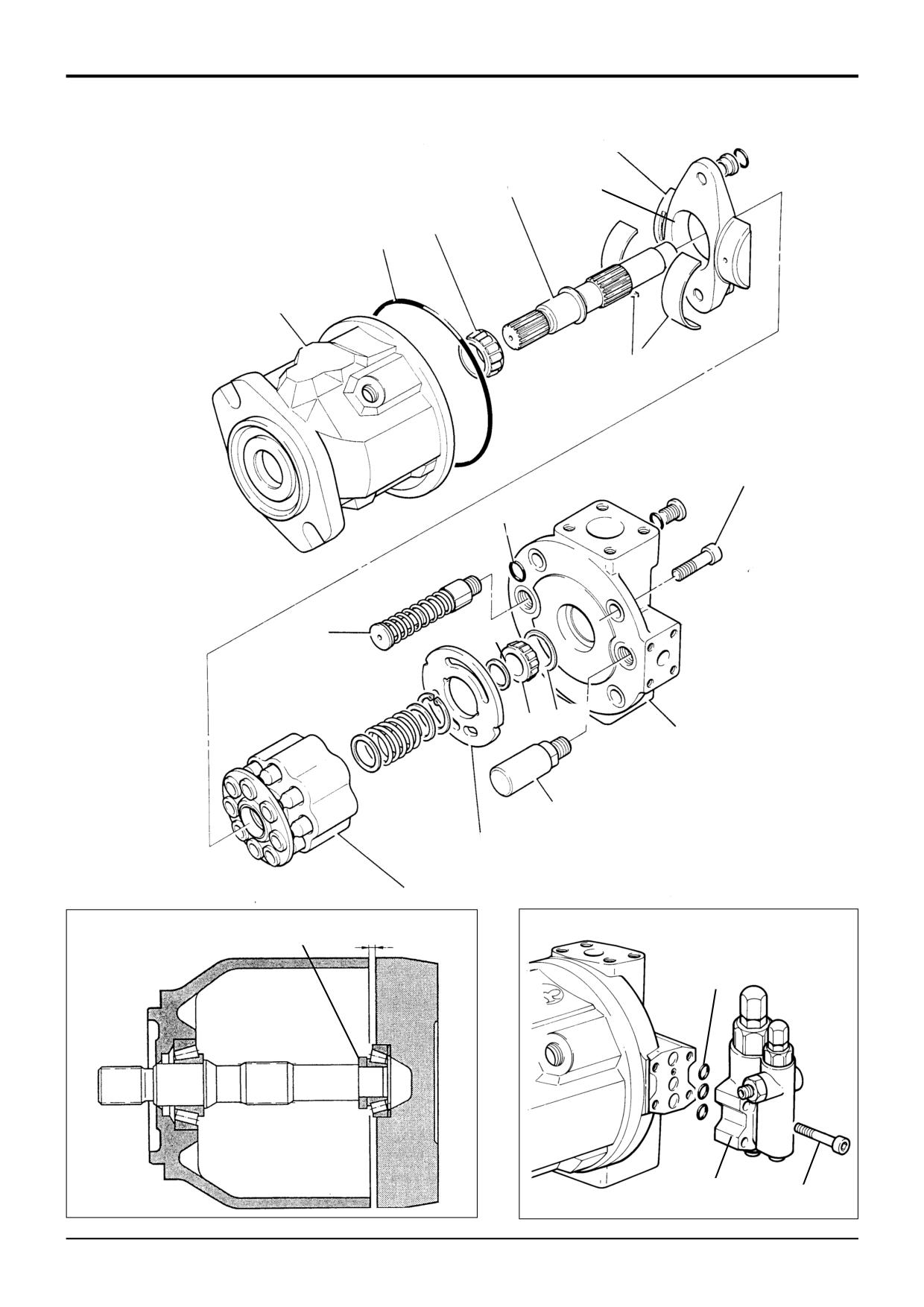
Dismantling and Assembly
11
C
15
13
4
14
5
18
8
10
S272610
17
9
3
7
6
12
B
A
18
2
S272640
S213160
1
9803/3280
Issue 1
Section E
Hydraulics
Section E
35 - 2
Main Pump
35 - 2
Variable Flow
Inspecting Parts
Generally check all pump parts for damage and/or wear. Any
Dismantling and Assembly
parts that are scored or damaged must be replaced with new
ones.
Before removing and dismantling the pump, make sure it is
the pump that is at fault. Complete all the necessary checks
The shaft ‘O’ ring grooves and all sealing faces must be free
as detailed in Service Procedures, Variable Flow Pumps.
of burrs and scores. During assembly, make sure that the
Make sure that the exterior of the pump and working area is
rotary piston group move freely. Renew all ‘O’ rings and
thoroughly cleaned and free of possible sources of
seals.
contamination. Following removal of the pump from the
machine, transfer it to a clean dirt free environment ready for
Assembly
dismantling.
Assembly is generally a reversal of the dismantle procedure,
The variable displacement pump has matched-ground
but note the following:
components. For this reason, some items will only be
available as a sub-assembly, for instance the barrel and
The taper roller bearing must have a preload of 0.0 to
piston assembly.
0.05mm (0.0 to 0.002in.). If the original bearing and shim is
being fitted no preload adjustment is required. If a new
All the ‘O’ rings, seals and bearings are available in a kit form
bearing is installed a preload adjustment is required:
from your JCB Distributor.
Preload Adjustment:
Dismantling
Install a setting shim of known thickness (as shown at
Refer also to Service Procedures, Variable Flow Pumps -
A). The shim thickness must be manufactured to a
Renewing Drive Shaft Seal.
tolerance of ± 0.01mm (0.0004in.). In this example the
shim thickness is 1.5mm.
1
Remove capscrews 1 (4 off) and detach the regulator
assembly 2 from the pump housing.
Fit the port plate item 3 and finger tighten the socket
screws. It is important that the socket screws are
2
Mark the position of the port plate 3 to pump housing 4.
tightened evenly and the port plate sits square.
3
Remove socket screws 5, and remove the port plate
Using feeler gauges measure the gap B between the
together with the valve plate 6, control piston 7 and
port plate and the pump housing 4. Measure in more
stroking piston 8. Hold the plate in position during
than one position to establish the port plate is fitted
removal.
evenly. Obtain shim thickness (dimensions in mm):
4
Remove taper roller bearing 9 and shim 10 from the
Example measured gap
1.26
drive shaft 11.
Subtract preload
- 0.05
5
Remove the rotary piston assembly 12 from the pump
Total
1.21
housing. Assembly includes shaft 11, bearing 15, and
cradle 16.
Known shim thickness
1.50
Subtract calculated preload
-1.21
6
Remove and discard port plate to pump housing ‘O’
ring 13.
SHIM THICKNESS
0.29
7
Remove bearing shells 14 and disc 17.
When the shim thickness has been calculated, remove the
setting shim A and fit the required shim (in this instance the
8
Remove the outer bearing races (not shown) from the
shim would be 0.29mm).
pump housing and the port plate. Only remove the
races if they are damaged and unserviceable.
Note: Setting shim A is not currently available as a service
tool. The shim (and the calculated shim) can be
9
Lift the valve plate 6 off the port plate, do not lose the
manufactured locally. Maintain a tolerance of ± 0.01mm
dowel pins (not shown).
(0.0004in.).
10
Remove and discard ‘O’ rings 18.
The lubrication bore relief (item C) on the cradle must be
fitted on the pressure side of the pump.
11
Remove control piston 7. Note that the control piston is
mounted on the same side as the regulator valve.
Check the control piston and the stroking piston move
smoothly.
12
Remove the stroking piston assembly 8.
The regulator valve assembly is currently a non serviceable
Further dismantling and assembly of the pump is not
part.
recommended.
9803/3280
Issue 1
Section E
Hydraulics
Section E
50 - 1
Loader Valve - Fixed Flow
50 - 1
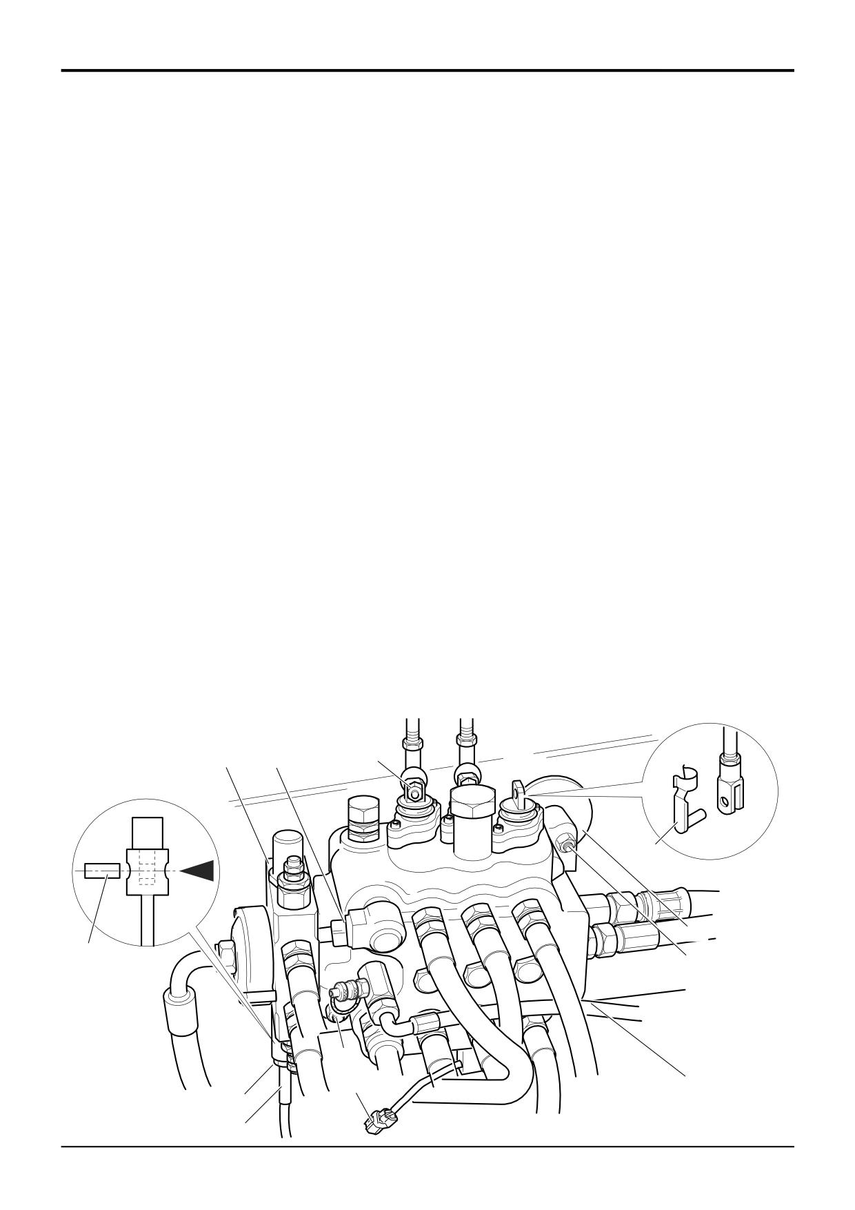
Removal and Replacement
Manual Control
! WARNING
3
Disconnect all hydraulic hoses from the valve block
Make the machine safe before working underneath it.
and plug all orifices to prevent ingress of dirt. Label
Park the machine on level ground, lower the arms. Apply
each hose before disconnecting, this will ensure
the parking brake, put the transmission in neutral and
correct position when refitting.
stop the engine. Chock both sides of all four wheels.
*4
Uncouple the dump solenoid electrical connector G.
Disconnect the battery, to prevent the engine being
Uncouple the electric detent connector H (if fitted).
started while you are beneath the machine.
GEN-1-2
*
5
Loosen and remove the three fixing nuts J. Remove the
! DANGER
loader valve and spacing washers C.
Hydraulic fluid at system pressure can injure you. Before
Replacement
disconnecting or connecting hydraulic hoses, stop the
engine and operate the controls to release pressure
Replacement is a reversal of the removal sequence.
trapped in the hoses. Make sure the engine cannot be
started while the hoses are open.
INT-3-1-11/1
! WARNING
Fine jets of hydraulic fluid at high pressure can
Removal
penetrate the skin. Do not use your fingers to check for
hydraulic fluid leaks. Do not put your face close to
* Note: The illustration shows a valve fitted with a bolt on
suspected leaks. Hold a piece of cardboard close to
auxilary spool 1. This item is only fitted to some machines,
suspected leaks and then inspect the cardboard for
typically Precision Control machines with extending dipper.
signs of hydraulic fluid. If hydraulic fluid penetrates your
skin, get medical help immediately.
*1
Operate the valve block levers back and forth to vent
INT-3-1-10/1
residual pressure. On Precision Control machines also
operate the extending dipper foot pedal (if fitted).
After replacement check the main relief valve (M.R.V.) and
auxiliary relief valve (A.R.V.) pressure settings.
*2
Remove clevis pins A and nuts B to disconnect the
control levers from the valve block spools. Disconnect
Note: All hydraulic adapters that are installed together with
the control cable D (if fitted). Undo the lock nut E. Undo
a bonded sealing washer must also have JCB Threadseal
the housing fixing screws and slide it down the cable.
applied to the threads of the adapter.
Remove the pin F.
1
G
B
A
C
F
J
J
J
H
E
A402470
D
9803/3280
Issue 2*
Section E
Hydraulics
Section E
50 - 6
Loader Valve - Fixed Flow
50 - 6
S262710
11
10
2
9
1
8
7
13
6
4
14
5
12
3
S262720
9803/3280
Issue 1
Section E
Hydraulics
Section E
50 - 7
Loader Valve - Fixed Flow
50 - 7
Dismantling and Assembly
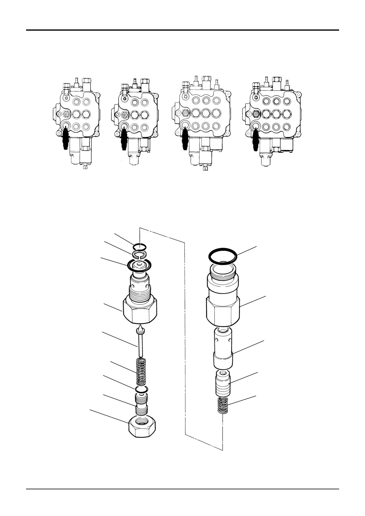
Main Relief Valve (MRV)
Assembly
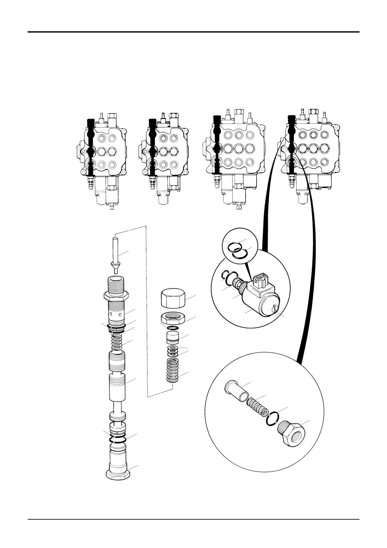
The numerical sequence shown on the illustration is intended
as a guide to dismantling.
Renew all 'O' rings and back-up rings.
For assembly the sequence should be reversed.
Lubricate parts with JCB Hydraulic Fluid before assembling.
Make sure that all the parts move freely.
The following points MUST be avoided when dismantling
and assembling the valve:
Make sure that the 'O' rings and back-up rings are fitted the
•
CONTAMINATION
correct way, items 10 and 11.
•
DAMAGE TO SPOOL
•
DAMAGE TO SEAL GROOVES
Adjust pressure setting as required, refer to Service
Procedures, Loader Valve - Pressure Testing.
All or any of the above points may result in possible
problems with the valve.
Torque Settings
Dismantling
Item
Nm
kgf m
lbf ft
When removing 'O' rings and seals, use an appropriately
3
5.4
0.6
4
rounded tool that WILL NOT cause any damage to the seal
grooves.
Discard ALL 'O' rings and back up rings. DO NOT use worn
or damaged items.
Inspect the valve components for scratches, nicks or any
other type of damage, replace with new if required.
9803/3280
Issue 1
Section E
Hydraulics
Section E
50 - 8
Loader Valve - Fixed Flow
50 - 8
1
18
2
17
3
16
4
15
5
6
8
9
10
11
14
B
13
12
A
7
S197420
9803/3280
Issue 1
Section E
Hydraulics
Section E
50 - 9
Loader Valve - Fixed Flow
50 - 9
Dismantling and Assembly
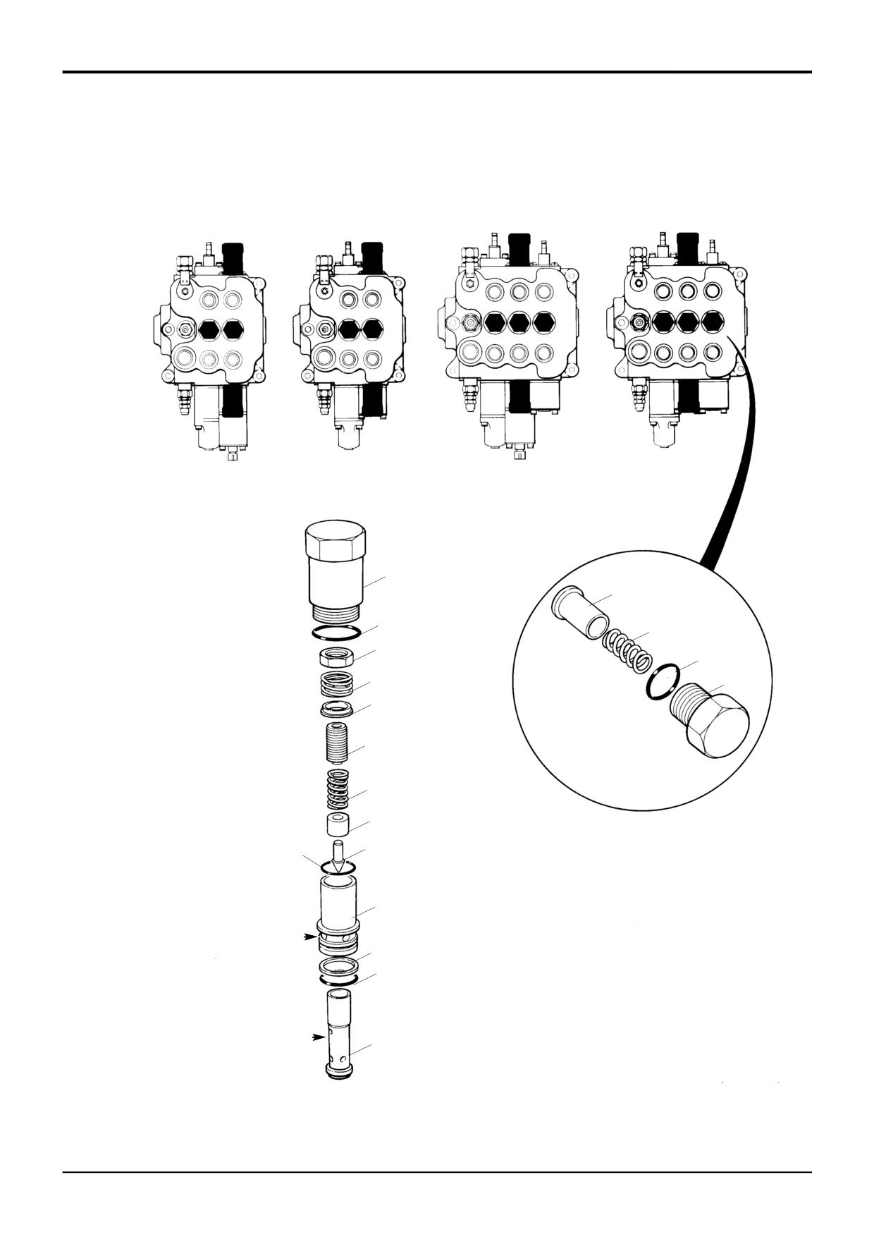
Auxiliary Relief Valves (ARV) and
Assembly
Load Hold Check Valves (LHCV)
Renew all 'O' rings and back-up rings.
The numerical sequence shown on the illustration is intended
as a guide to dismantling.
Lubricate parts with JCB Hydraulic Fluid before assembling.
Make sure that all the parts move freely.
For assembly the sequence should be reversed.
Fit back-up ring 13 on the upper side of 'O' ring 12.
The following points MUST be avoided when dismantling
and assembling the valve:
Fit flat face of sleeve 9 against shoulder of poppet 10.
•
CONTAMINATION
Torque tighten item 14 using the special tool (see Service
•
DAMAGE TO SPOOL
Tools), until its shoulder seats firmly against item 1.
•
DAMAGE TO SEAL GROOVES
All or any of the above points may result in possible
Pressure test the relief valves, refer to Service Procedures,
problems with the valve.
Loader Valve - Pressure Testing.
The ARV's are identical in design but have different pressure
Torque Settings
settings, refer to Technical Data.
Item
Nm
kgf m
lbf ft
The LHCV's are identical.
1
65
6.6
48
3
24
2.5
18
Dismantling
15
81
8.3
60
When removing 'O' rings and seals, use an an appropriately
rounded tool that WILL NOT cause any damage to the seal
grooves.
Discard ALL 'O' rings and back up rings. DO NOT use worn
or damaged items.
Dismantle sub-assembly 14 from item 1 using a special tool
(see Service Tools). The special spanner locates in cross
holes B.
Make sure that small drilling A is not blocked.
Ensure good condition of seating faces on poppet 18 and on
the mating face of the valve block.
Inspect the valve components for scratches, nicks or any
other type of damage, replace with new if required.
9803/3280
Issue 1
Section E
Hydraulics
Section E
50 - 10
Loader Valve - Fixed Flow
50 - 10
3
4
23
7
15
6
5
19
16
2
1
25
18
24
17
26
21
22
27
11
10
9
8
14
13
12
S197430
9803/3280
Issue 1
Section E
Hydraulics
Section E
50 - 11
Loader Valve - Fixed Flow
50 - 11
Dismantling and Assembly
Unloader Valve
Assembly
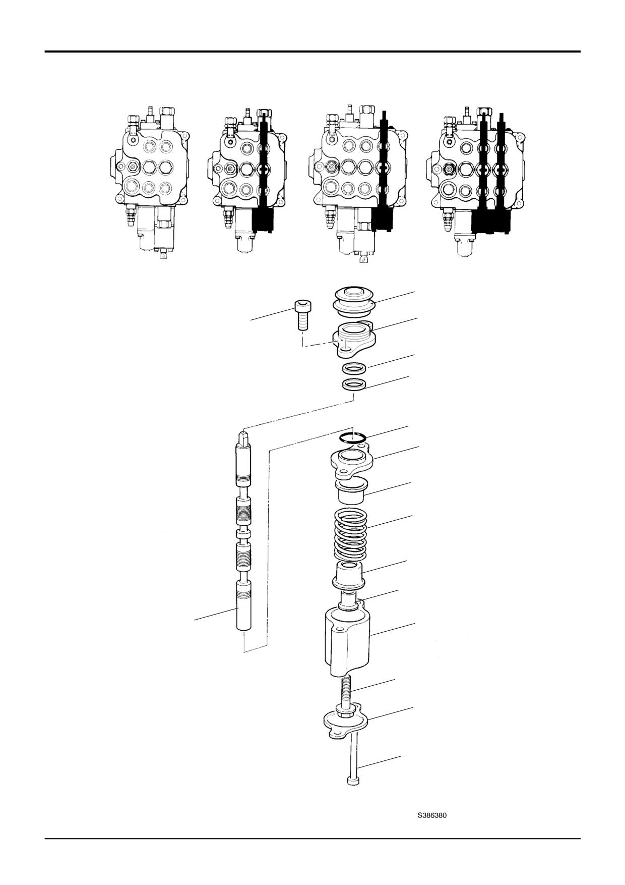
The numerical sequence shown on the illustration is intended
Renew all 'O' rings and back-up rings.
as a guide to dismantling.
For assembly the sequence should be reversed.
Lubricate parts with JCB Hydraulic Fluid before assembling.
Make sure that all the parts move freely.
The following points MUST be avoided when dismantling
Ensure that the small drilling through the centre of items 23,
and assembling the valve:
is clear.
•
CONTAMINATION
•
DAMAGE TO SPOOL
Shims 21 are intended to limit the maximum pressure
•
DAMAGE TO SEAL GROOVES
setting, the specified pressure setting is achieved by
adjusting capnut 15. If the specified pressure cannot be
All or any of the above points may result in possible
achieved under test, it is permissible to add shims as
problems with the valve.
required. There MUST be at least one hardened shim next
to the spring item 22.
Dismantling
Do not over-tighten the solenoid assembly, it may effect the
When removing 'O' rings and seals, use an an appropriately
operation of the solenoid, use the spanner flats and torque
rounded tool that WILL NOT cause any damage to the seal
tighten to figure indicated in the table below (items 1 and 5).
grooves.
Fit chamfered end of spring 22 against head of pilot poppet
Discard ALL 'O' rings and back up rings. DO NOT use worn
item 23.
or damaged items.
Check pressure setting after refitting, refer to Service
Use a nylon rod to push out spool assembly item 23, DO
Procedures, Loader Valve - Pressure Testing.
NOT damage spool bore.
Check the operation of the hydraulic speed control, refer to
Inspect the valve components for scratches, nicks or any
Service Procedures, Loader Valve - Pressure Testing.
other type of damage, replace with new if required.
Torque Settings
Item
Nm
kgf m
lbf ft
1
6.7
0.7
5
5
27
2.8
20
8
81
8.3
60
12
81
8.3
60
16
45
4.6
33
19
34
3.5
25
9803/3280
Issue 1
Section E
Hydraulics
Section E
50 - 12
Loader Valve - Fixed Flow
50 - 12
1A
2
1
3
4
15
14
13
12
11
10
8
7
9
6
5
9803/3280
Issue 1
Section E
Hydraulics
Section E
50 - 13
Loader Valve - Fixed Flow
50 - 13
Dismantling and Assembly
Standard Spool - Manual
Assembly
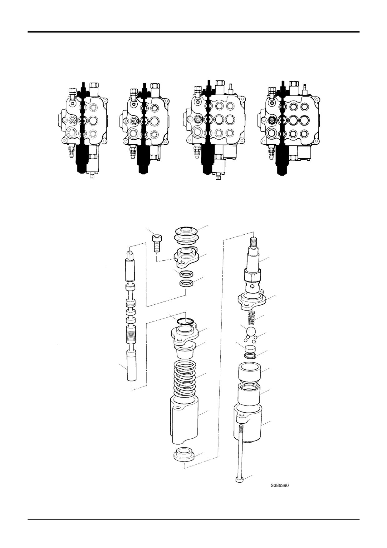
The numerical sequence shown on the illustration is intended
as a guide to dismantling.
1
Fit the boot 1A to the seal plate 2.
For assembly the sequence should be reversed.
2
Fit a new lipseal 4 into the valve block, ensure square.
Fit wiper 3 on top of lipseal.
The following points MUST be avoided when dismantling
3
Fit the seal plate and boot assembly to valve block
and assembling the valve:
section but do not torque tighten capscrews 1 at this
•
CONTAMINATION
stage. Ensure wiper locates into seal plate.
•
DAMAGE TO SPOOL
4
Use clean hydraulic oil as a lubricant. From the bottom,
•
DAMAGE TO SEAL GROOVES
insert spool through the valve block, do not use
All or any of the above points may result in possible
excessive force when fitting, a turning motion should
problems with the valve.
ease the spool through the valve block.
5
Check that the tang end of the spool passes through
Dismantling
the boot without dislodging or damaging the boot.
Remove the lever linkage from the tang (lever) end of the
Ensure that the tang aligns with the control rod and
that the boot is not distorted and is located in the spool
spool.
land.
When removing 'O' rings and seals, use an appropriately
6
Torque tighten cap screws 1.
rounded tool that WILL NOT cause any damage to the spool
or seal grooves, for instance, item 3, which is a wiper seal
7
When fitting bolt 9, clean the threads thoroughly using
and is a press fit in the counterbore.
JCB Cleaner/Degreaser, leave it for 10 minutes then
apply a small quantity of JCB Threadlocker and Sealer
Care must be taken to ensure that the spool 8 is not
to the threads of the spool.
damaged when removing it from the valve block.
8
Make sure that all the parts move freely, check that
Hold the spool in clamp 992/10100, unscrew bolt 9 and
item 10 does not interfere with item 13.
remove spring 12, spacer 10 and cups 11 and 13.
9
Renew 'O' ring15. Make sure the 'O' ring is not trapped
Check for surface contamination on the under side of the
or damaged.
seal plates 2 and 14. Clean if necessary. Check for the
flatness of the seal plate. If found to be bent - replace with
10
Fit seal 15 and seal plate 14 to the valve block section.
new (any work previously carried out on this valve may have
Torque tighten capscrew 5 on completion.
resulted in the bending of the seal plate).
Re-connect the lever mechanism to the tang (lever) end of
the spool.
Run the engine and inspect the valve for external leaks.
Torque Settings
Item
Nm
kgf m
lbf ft
1
9.5
0.96
7
5
9.5
0.96
7
9
9.5
0.96
7
9803/3280
Issue 1
Section E
Hydraulics
Section E
50 - 14
Loader Valve - Fixed Flow
50 - 14
2
1
3
20
4
5
11
15
19
18
14
10
23
17
16
13
9
22
8
12
7
21
6
9803/3280
Issue 1