JCB 3CX, 4CX, 214e, 214, 215, 217 & VARIANTS Backhoe Loader. Service Manual - page 15
Section E
Hydraulics
Section E
8 - 21
Circuit Descriptions
8 - 21
LS
PC
P1
P2
Bucket
Actuation
Key to Oil Flow & Pressure
A405050
Full Pressure
Pressure
Servo
Neutral
Exhaust
Cavitation
Lock Up
A390630
LS
PC
Bucket
Boom
Actuation
Actuation
A405060
9803/3280
Issue 1
Section E
Hydraulics
Section E
8 - 22
Circuit Descriptions
8 - 22
Excavator Valve
Precision Control (Servo) (continued)
(Machines from January 2003)
Load Sense - Pressure Compensator Valves
Operation
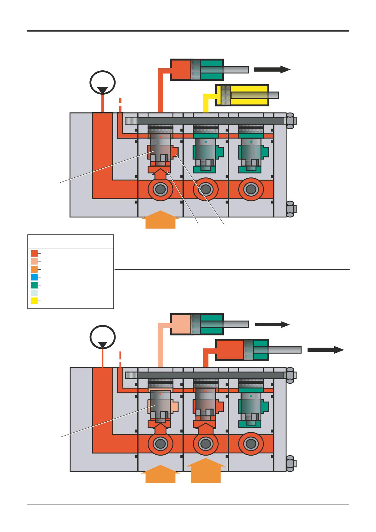
Operating an individual service
It must be noted that the load sense gallery LS is connected
to all the pressure compensator valves PC (one for each
service) as shown. The pressure in the load sense gallery LS
will always be equal to the highest load from any of the
backhoe services.
The pressure compensator valves are fitted between each
service spool and service ram and sense the pressure acting
on either side of the particular service spool. The pressure
compensator valve will move in response to the pressure
drop (pressure differential) created across the spool.
When one service only is operated the pressure
compensator valve PC is FULLY opened as shown,
connecting the gallery P1 to gallery P2 and to the ram
service port without any pressure drop.
Operating multiple services
a) Normal Condition
b) With insufficient flow from pump
When another service with a higher load is operated
Should the oil flow demanded by the sum of the combined
simultaneously, a typical example is the lifting of the boom
services operating ever exceed that of the pump, all the
and simultaneous operation of the bucket as shown.
pressure compensator valves will partially close accordingly,
effectively dividing the available flow between all the services
The higher load pressure in the boom service causes the
proportionally.
pressure compensator valve PC in the bucket service to
partially close, reducing the size of the opening through
In this condition the service ram with the highest load will
which the oil must flow, and in this way maintains a pressure
NOT stop, because the speed of the other service rams
drop across the pressure compensator equal to the pressure
operating will have been reduced proportionaly by the action
drop across the bucket service spool.
of the pressure compensator valves to compensate.
In this example, because of the action of the pressure
When one of the service spools is returned to neutral, the
compensator valve the bucket service is always kept
speed of the other service rams still operating will all
independant of the other services, the bucket ram speed
increase proportionally.
remains constant (as controlled by the bucket service spool)
and is not affected by the greater operating pressure in the
boom service.
9803/3280
Issue 1
Smooth Ride System
1
1
4
3A
1
3E
3F
3J
3B
3J
3C
1
3G
3H
3J
3D
4
P1
P2
3
T
T
ACC
3
2
A391100
2
S307310
Smooth Ride System
Component Key:
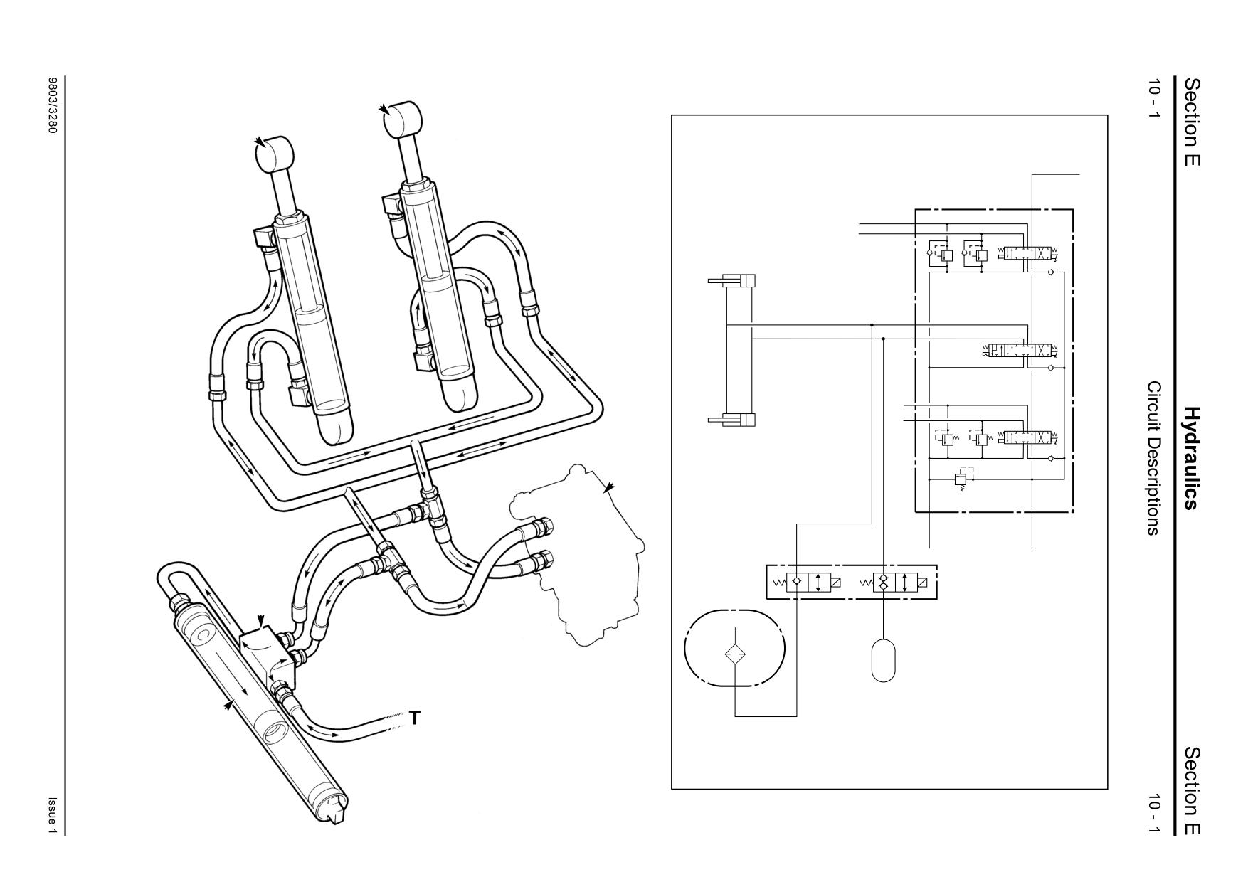
Smooth Ride System (SRS) will enhance the
comfort of the ride by damping out the forces
1 Loader Lift Rams
imposed on the machine by the movement of the
2 Accumulator
loader arms as the machine travels over uneven
3 Solenoid Valve Block
surfaces.
4 Loader Valve Block
T Tank
This is achieved by connecting the head side of the
loader arms 1 to a pressurised piston type
accumulator 2.
When a switch in the cab is operated, selector
valve 3 is energised and opens. Hydraulic oil from
the piston head side is dead ended at the loader
valve block 4 but is connected to the accumulator.
The rod side of the loader ram is connected to tank
T via the selector valve to make up or dissipate oil
as required.
Note: The smooth ride system will not function on
machines fitted with hose burst check valves.
Section E
Hydraulics
Section E
11 - 1
Circuit Descriptions
11 - 1
Hose Burst Protection Valve
BOOM RAM
Boom & Dipper Operation
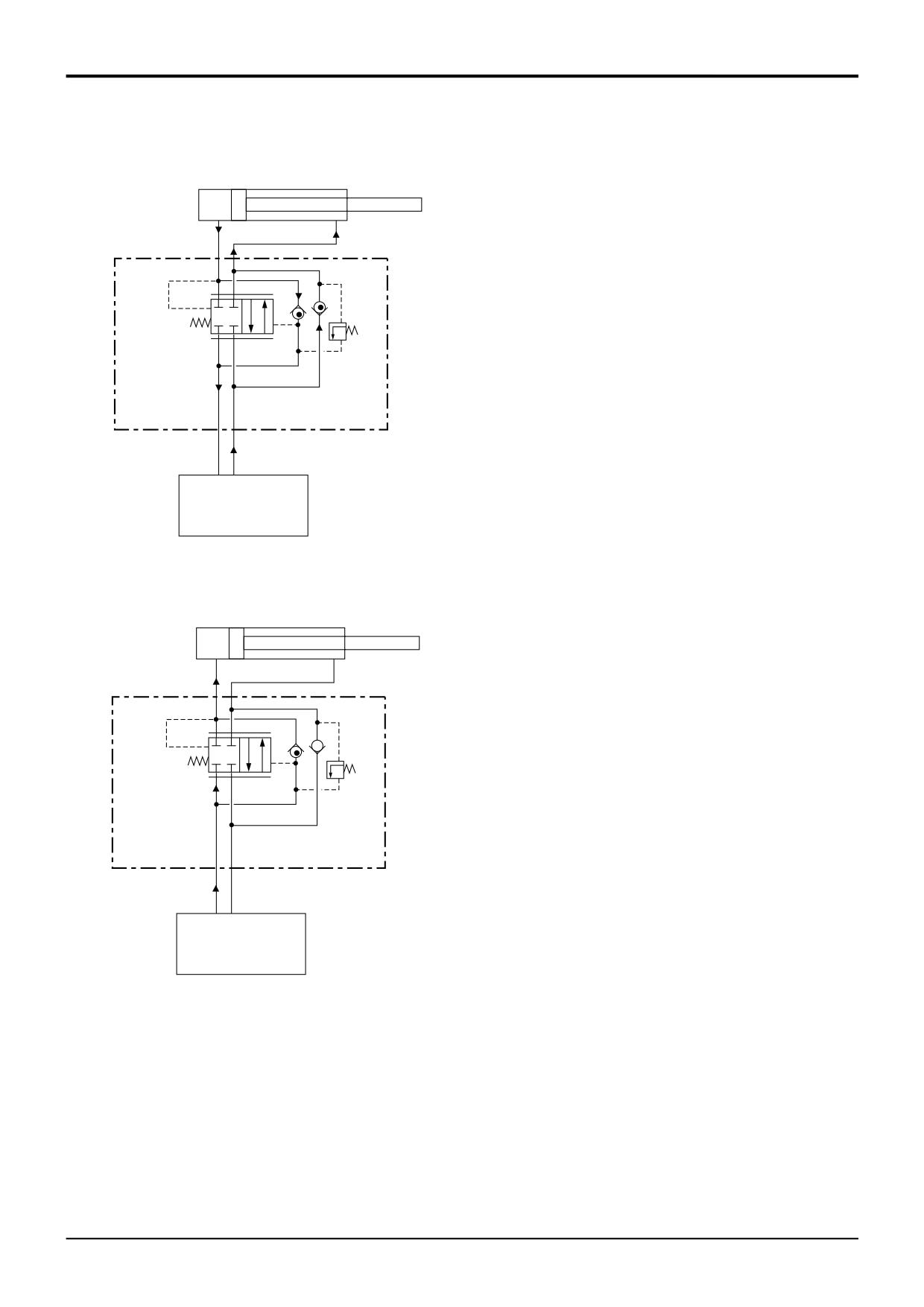
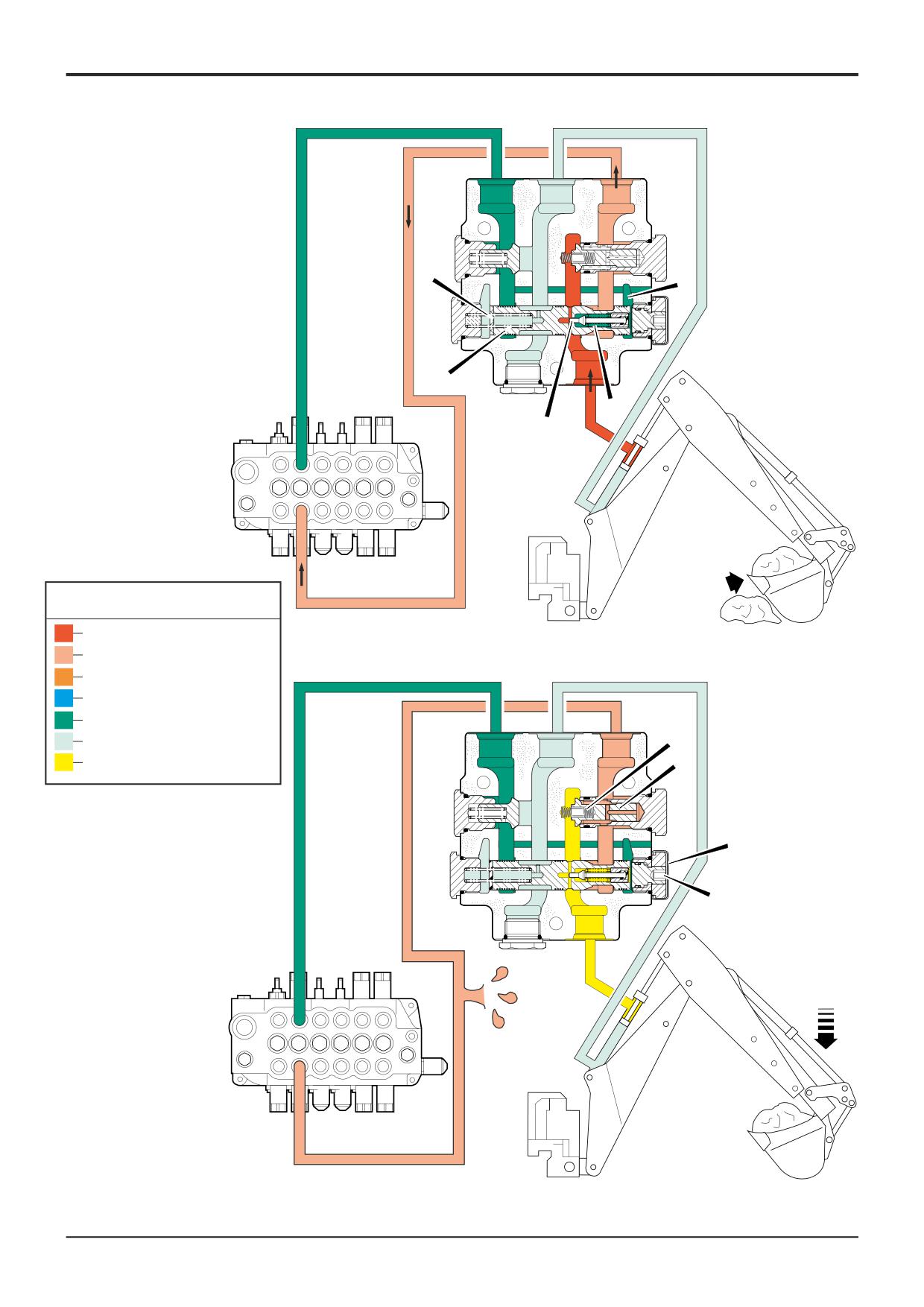
The small letter annotations A, B, X, and Y are stamped on
the valve.
X
Y
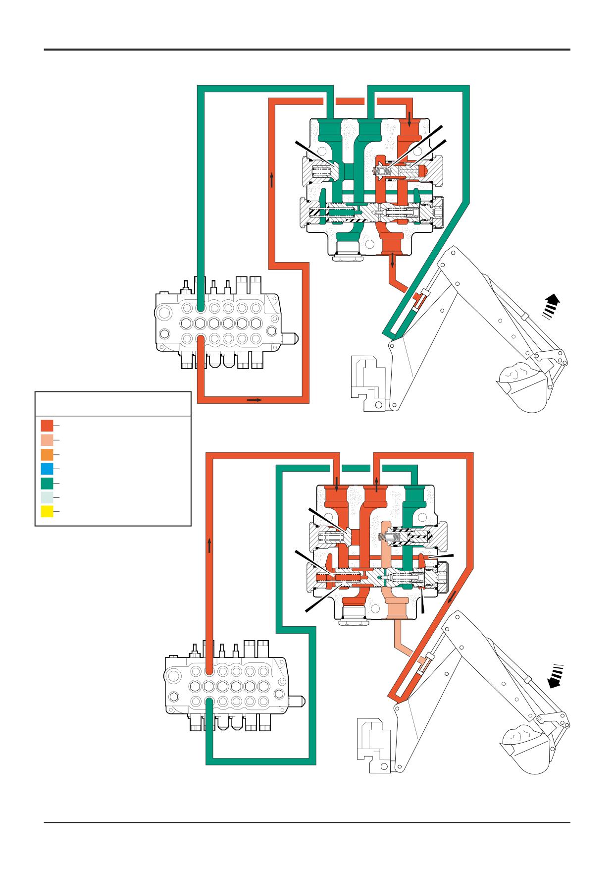
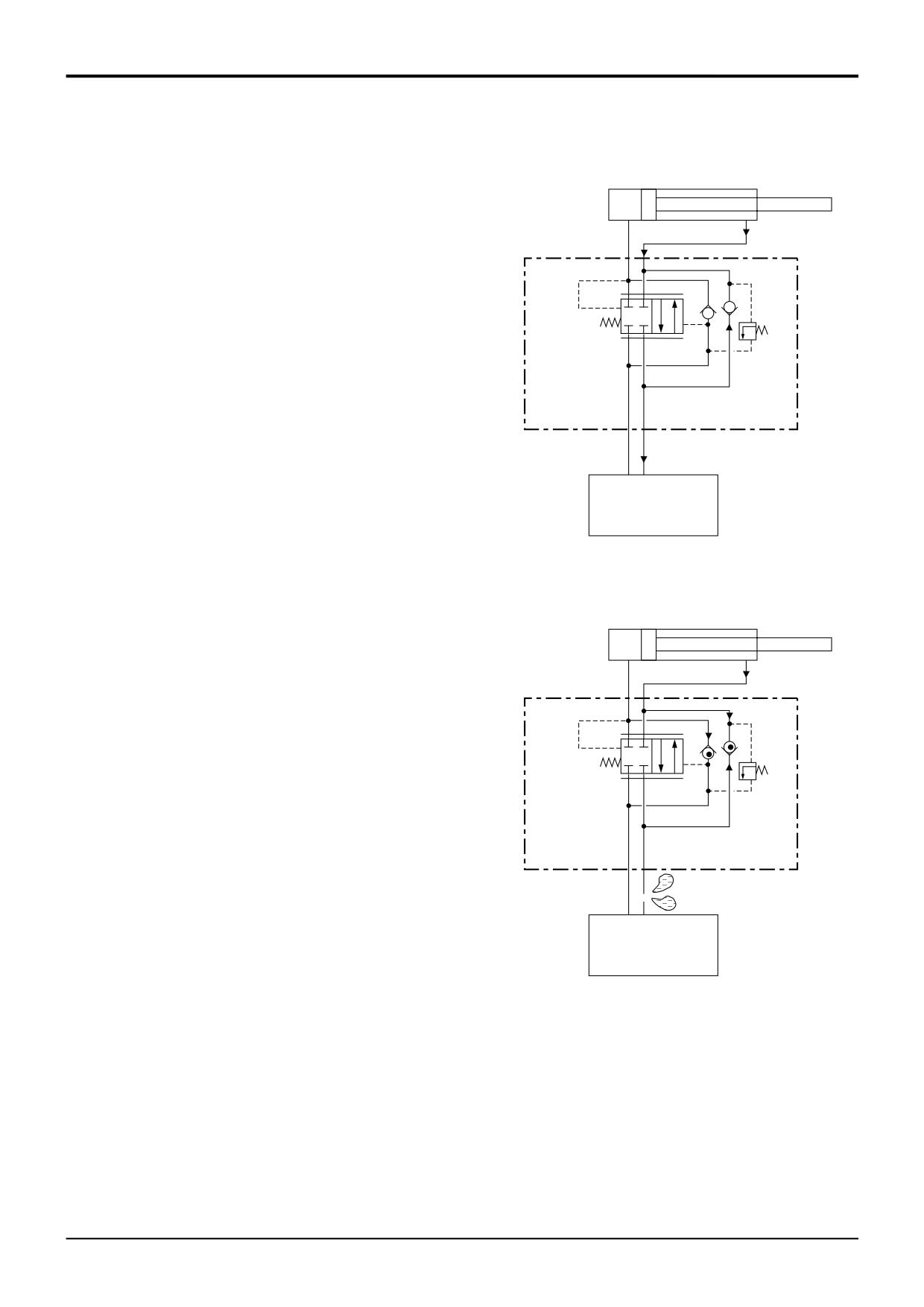
Operation 1 - Load Raise
C
When 'dipper out' is selected, oil from the excavator valve
block is fed to port B, the oil opens check valve C against
spring D and passes through internal galleries into the rod
(raise) side of the ram via port Y.
E
Oil from the head side of the ram enters at port X, opens
check valve assembly E and returns to tank via port A and
the excavator valve block.
A
B
BACKHOE VALVE
A323040
BOOM RAM
Operation 2 - Load Lower
X
Y
Oil from the excavator valve block is fed to port A. The
connection to the head side of the ram is blocked by the
check valve assembly E and the position of spool F.
A cross drilling G in the valve connects the A port gallery to
cavity J. The pressure in cavity J increases to such a point
that it moves spool F to the left against the force of spring H.
The new position of the spool creates a connection between
E
the A port gallery and the head side of the dipper ram (via
port X).
A
B
There is also a connection between the Y port gallery and
the B port gallery. Oil from the rod side of the ram enters at
port Y and returns to tank via port B and the excavator valve
block.
BACKHOE VALVE
A323041
Component Key:
C Check Valve
D Spring
E Check Valve Assembly
F Spool
G Cross Drilling
H Spring
J Cavity
9803/3280
Issue 1
Section E
Hydraulics
Section E
11 - 2
Circuit Descriptions
11 - 2
(A)
(X)
(B)
D
E
C
(Y)
Key to Oil Flow & Pressure
Full Pressure
Pressure
A395760
Servo
Neutral
(A)
(X)
(B)
Exhaust
Cavitation
E
Lock Up
A390630
H
G
F
J
(Y)
A395770
9803/3280
Issue 1
Section E
Hydraulics
Section E
11 - 3
Circuit Descriptions
11 - 3
(A)
(X)
(B)
H
J
F
(Y)
L
K
Key to Oil Flow & Pressure
Full Pressure
Pressure
A395780
Servo
Neutral
Exhaust
(A)
(X)
(B)
Cavitation
D
Lock Up
C
A390630
A
B
(Y)
A395790
9803/3280
Issue 1
Section E
Hydraulics
Section E
11 - 4
Circuit Descriptions
11 - 4
Hose Burst Protection Valve
BOOM RAM
Boom & Dipper Operation (Cont’d)
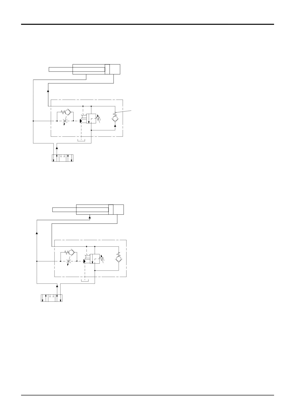
Operation 3 - Relief Valve
If during normal operation the pressure in the rod side of the
X
Y
dipper ram increases (for example, by the operation of the
bucket against an obstacle), increasing pressure in the ram
L
enters at port Y. The position of spool F prevents this
increasing pressure from venting back to the tank. The
H
pressure increases to such a point that it moves plunger K
off its seat (to the right) against the force of spring L.
F
K
The new position of plunger K opens a connection to cavity
J, the pressure is high enough to move spool F to the left
against the force of spring H. The new position of the spool
A
B
creates a connection from the rod side of the ram to port B.
Note that oil exhausted via port B will not reduce to low
pressure until the A.R.V. in the excavator valve block also
opens.
BACKHOE VALVE
A323042
BOOM RAM
Operation 4 - Hose Burst Condition
If a burst hose or other leakage occurs in the feed to the rod
X
Y
(raise) side of the ram, check valve C will be kept firmly held
on its seat by the back pressure generated due to the weight
C
the load in the bucket and the force of spring
D.
Oil trapped between the valve and the ram will prevent
movement of the load. To lower the load, see Lowering The
E
Load.
A
B
BACKHOE VALVE
A323043
Component Key:
C Check Valve
D Spring
F Spool
H Spring
J Cavity
K Plunger
L Spring
9803/3280
Issue 1
Section E
Hydraulics
Section E
11 - 5
Circuit Descriptions
11 - 5
Hose Burst Protection Valve
22
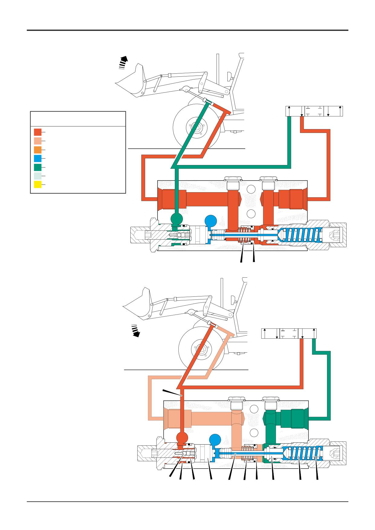
Loader Operation
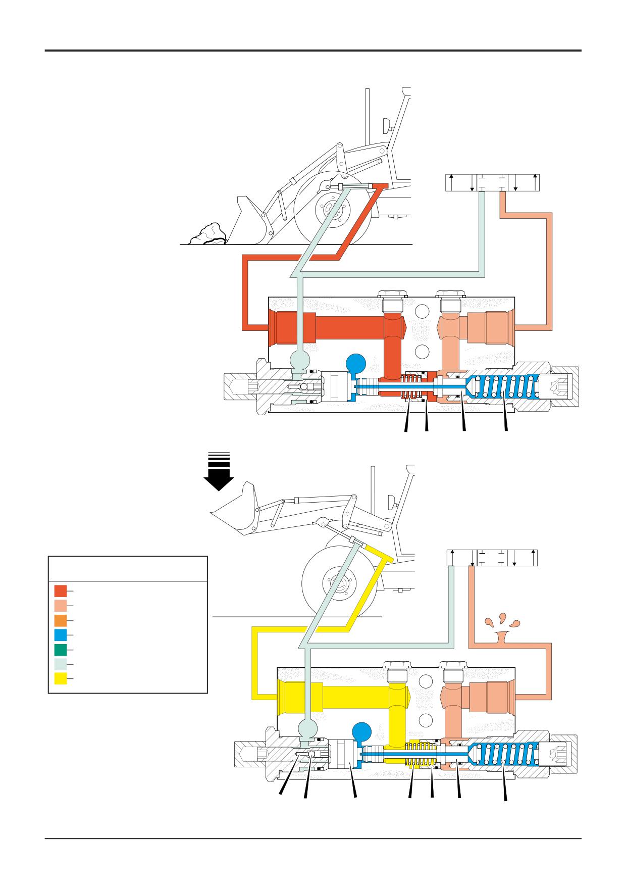
The small letter annotations V2, C2, P, T and E are the same
as the port markings found on the HBPV.
Operation 1 - Load Raise
E
When lift is selected, oil from the loader valve block 9 is fed
to port V2 on the HBPV, the oil opens check valve sleeve A
against spring B and passes through internal galleries into
C2
B
the (raise) side of the ram via port C2.
P
Oil from the lower side of the ram returns to tank via port P
A
and the loader valve block.
T
V2
A323090
9
22
Operation 2 - Load Lower
Oil from the loader valve block 9 is fed directly to the (lower)
side of the ram. A pilot line C from the service line is
connected to the HBPV at port P.
L
Oil enters the HBPV at port P and passes through drilling D,
down threads F and acts on the end face of piston G. The
C2
J
pressure is sufficient to move piston G to the right, thus
moving plunger J off its seat against spring H. With the
P
plunger off its seat, oil from the opposite side of the ram
H
enters the HBPV at port C2, passes through the HBPV and
D
G
returns to tank via port V2 and the valve block.
C
T
V2
A drilled hole N through the centre of plunger J connects
chamber Q to atmosphere T, this prevents the pressure in
chamber Q from rising to such a point that it would prevent
9
A323091
any movement of plunger J.
Threads F and the one-way check valve ball L act as
restrictors to 'dampen' any adverse effects of operating the
Component Key:
control levers erratically.
A Check Valve Sleeve
B Spring
C Pilot Line
D Drilling
F Thread
G Piston
H Spring
J Plunger
L Ball
N Orifice
Q Chamber
9 Loader Valve Block
9803/3280
Issue 1
Section E
Hydraulics
Section E
11 - 6
Circuit Descriptions
11 - 6
9
Key to Oil Flow & Pressure
Full Pressure
Pressure
Servo
Neutral
Exhaust
Cavitation
Lock Up
A390630
(C2)
(V2)
(P)
(T)
(E)
B
A
A395800
9
C
(C2)
(V2)
(P)
(T)
(E)
L
D
F
G
N
B
A
J
H
Q
A395810
9803/3280
Issue 1
Section E
Hydraulics
Section E
11 - 7
Circuit Descriptions
11 - 7
9
(C2)
(V2)
(P)
(T)
(E)
B
A
J
H
A395820
9
Key to Oil Flow & Pressure
Full Pressure
Pressure
Servo
Neutral
Exhaust
Cavitation
Lock Up
A390630
(C2)
(V2)
(P)
(T)
(E)
K
L
G
B
A
J
H
A395830
9803/3280
Issue 1
Section E
Hydraulics
Section E
11 - 8
Circuit Descriptions
11 - 8
Hose Burst Protection Valve
Loader Operation (Cont’d)
22
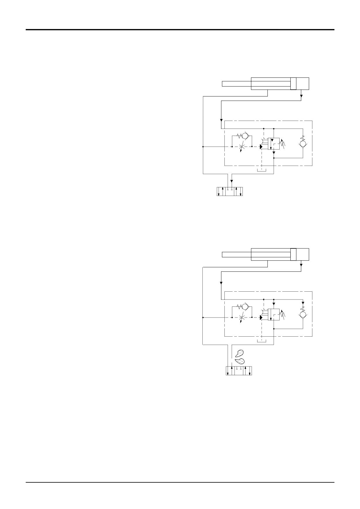
Operation 3 - Relief Valve
If during normal operation the pressure in the ram increases
(for example, by the operation of the bucket against an
obstacle), increasing pressure in the ram enters the HBPV at
C2 and will be sensed on the face of plunger J. When the
force of spring H is exceeded, the plunger is made to move
off its seat thus allowing oil to flow through the valve to port
C2
J
V2.
Note: Oil exhausted via port V2 will not reduce to low
P
H
pressure until the A.R.V. in the valve block 9 also opens.
T
V2
9
A323092
22
Operation 4 - Hose Burst Condition
In the event of a hose burst or other leakage in the feed to
the HBCV, plunger J will be held on its seat by the force of
spring H. Also, back pressure and the force of spring B will
hold check valve seat A firmly against the plunger, thus
trapping a column of oil in the head side circuit which will
prevent the load from dropping.
C2
K
L
J
B
A
Note that before the plunger can move onto its seat, the
pressure on the pilot side of the piston G must vent to
P
H
atmosphere quickly, therefore ball L will open against the
G
force of spring K which allows the oil to vent down the
threads AND through the drilling previously plugged by ball
T
V2
L.
A323093
9
Component Key:
A Check Valve Seat
B Spring
G Piston
H Spring
J Plunger
K Spring
L Ball
9 Loader Valve Block
9803/3280
Issue 1
Section E
Section E
Hydraulics
15 - 1
Fault Finding
15 - 1
Hydraulic System
Introduction
- Fixed Flow
The purpose of this section is to help you trace hydraulic
faults to a faulty unit (valve, actuator, ram etc). Once you
Fault Finding Contents
have traced the faulty unit, refer to the appropriate
dismantling, inspecting and test instructions given elsewhere
Page No.
in the hydraulics section.
To help identify circuits, valves, rams etc mentioned in the
Introduction
15 - 1
fault finding procedures, refer to the hydraulic schematic
Lack of power in all hydraulic functions
15 - 1
diagrams (near the beginning of the Hydraulics Section).
1
Before you begin fault finding, read the Safety
All hydraulic rams slow to operate
15 - 2
information at the beginning of this manual.
One hydraulic service fails to operate or is
slow to operate
15 - 2
2
Make simple checks before say, stripping a major
component.
The engine tends to stall when the
3
Make sure that the hydraulic fluid is at correct working
hydraulics are under load
15 - 2
temperature (50 °C, 122 °F).
A spool is sticking
15 - 3
4
What ever the fault, check the condition of the hydraulic
fluid. Drain and replace if necessary.
Leaking Oil Seal (Control Valves)
15 - 3
5
Make any relevant electrical checks before moving on
Ram creep
15 - 3
to the hydraulics.
Hydraulic oil becomes too hot
15 - 4
6
Be sure to remove ALL contamination and if possible
identify its origin. It may be part of a component from
elsewhere in the circuit.
7
Replace any seals such as 'O' rings before re-
assembling hydraulic components.
Fault
Probable Cause
Action
1
Lack of power in all hydraulic functions.
Insufficient hydraulic fluid.
Check for leaks and top up as required.
Hydraulic leaks in system.
Check hoses, replace as required.
Engine performance.
Check engine performance, see
transmission section for stall speed
test procedures.
Main relief valve (MRV)
Check and adjust as required.
setting incorrect.
Low pump flow.
Check pump flow, if required service or
replace pump.
Hydraulic tank breather
Clean or replace the breather
Tank filter by-pass valve
Check condition of hydraulic filter
Unloader valve pressure
Check pressure setting of the
setting too high
unloader valve.
..... continued
9803/3280
Issue 1
Section E
Section E
Hydraulics
15 - 2
Fault Finding
15 - 2
Fault
Probable Cause
Action
2
All hydraulic rams slow to operate.
Neutral circuit or low pressure
Check pipe lines and replace as required.
lines leaking, damaged, trapped
or kinked.
Low pump flow.
Check pump flow, if required service or
replace pump.
Priority valve operating.
Check if the priority valve is sticking,
rectify as required.
Main relief valve (MRV)
Check and adjust as required.
setting incorrect.
Unloader valve
Check if unloader valve is sticking, i.e.
dumping flow from pump section P2.
Tank filter by-pass valve
Check condition of hydraulic filter
Hydraulic tank breather
Clean or replace the breather
3
One hydraulic service fails to
Associated service pipe lines ,
Check hoses, replace as required.
operate or is slow to operate.
leaking damaged, trapped
or kinked.
Associated ram leaking.
Complete ram leakage check, replace
seals as required.
Auxiliary relief valve (ARV)
Check and adjust as required.
setting incorrect.
Associated valve block section
Check for leaks, rectify as required.
leaking or not operating.
Also, see fault 6 'Leaking Oil Seal
(Control Valves)'.
Make sure that the associated load hold
check valve is operating.
Check that the control lever and
associated linkages is operating
the spool, rectify as required. Also, see
fault 5, 'A spool is Sticking'.
Check valve malfunctioning
Test check valve, rectify as required.
(if fitted, e.g. stabiliser circuit)
Hose burst protection valve
Test HBPV, service as required.
(if fitted) malfunctioning.
Piston rod is bent
Replace piston rod, check pressure
settings of MRV and ARV.
Check that associated pivot pins are
adequately greased
4
The engine tends to stall when
M.R.V setting incorrect.
Check and adjust as required.
hydraulics are under load.
Poor engine performance.
Check engine performance, see
transmission section for stall speed
test procedures.
Unloader valve pressure
Check pressure setting of the
setting too high
unloader valve.
9803/3280
Issue 1
Section E
Section E
Hydraulics
15 - 3
Fault Finding
15 - 3
Fault
Probable Cause
Action
5
A spool is sticking.
Oil temperature abnormally high.
Check for correct fluid, see Lubricants
and Capacities. Check oil cooler and
grille for blockage.
The hydraulic fluid is dirty.
Clean the tank strainer. If strainer badly
clogged, drain and flush hydraulic system
Fill with clean hydraulic fluid.
The service pipe connection
Check tightening torque.
is over tightened.
The valve housing was twisted
Loosen retaining bolts and tighten to
during installation.
correct torque figures.
Pressure too high.
Check system pressure.
A control linkage is bent
Disconnect the linkage. Repair the
linkage if possible, or fit a new one
A spool is bent
Dismantle the control valve. Renew spool
as necessary.
A return spring is broken.
Renew as necessary.
A return spring or cap is out of
Remove the cap, check that the spring is
alignment.
in the correct position. Refit cap and
torque tighten bolts
Temperature distribution within
Warm the entire system up before
control valve not uniform.
using service.
6
Leaking Oil Seal (Control Valves)
Paint or dirt on the seal face.
Remove the seal and clean.
The back pressure in the valve
Check circuit pressures, adjust if
circuit is excessively high.
possible. Otherwise investigate
thoroughly.
Spool damaged.
Dismantle. Inspect all parts. Renovate or
renew as necessary.
The seal is not secured.
Clean the seal and tighten the retaining
bolts to the correct torque.
The seal is cut or damaged.
Fit a new seal.
7
Ram creep.
Associated ram or pipe lines from
Check and rectify as required.
ram leaking.
Check valve malfunctioning
Test check valve, rectify as required.
(if fitted, e.g. stabiliser circuit)
Associated valve section spools
Rectify, check for contamination.
leaking.
Associated ARV leaking
Rectify, check for contamination
Note: Refer also to Service Procedures, Ram Creep Tests - All Services
9803/3280
Issue 1
Section E
Section E
Hydraulics
15 - 4
Fault Finding
15 - 4
Fault
Probable Cause
Action
8
Hydraulic oil becomes too hot
Oil cooler obstructed
Remove debris from cooler fins
Restriction in neutral circuit
Check hoses, replace as necessary
lines
Hydraulic filter clogged and
Change hydraulic filter
by-pass valve not working
9803/3280
Issue 1
Section E
Section E
Hydraulics
15 - 10
Fault Finding
15 - 10
Hydraulic System
Introduction
- Variable Flow
This section details the possible faults that may be found
with the loader and backhoe valve blocks. The faults listed
Fault Finding Contents
only appertain to valve blocks fitted on variable flow
hydraulic machine systems (Rexroth valves).
Page No.
1
Before you begin fault finding, read the Safety
Introduction
15 - 10
information at the beginning of this manual.
High or low system pressure
15 - 10
2
Make simple checks before say, stripping a major
component.
Pump stays at high pressure
15 - 10
3
Make sure that the hydraulic fluid is at correct working
Pressure or flow obtained at one port only
15 - 10
temperature (50 °C, 122 °F).
No pressure or flow at either port
15 - 10
4
What ever the fault, check the condition of the
hydraulic fluid. Drain and replace if necessary.
High work port leakage
15 - 10
5
Make any relevant electrical checks before moving on
Leaks between sections
15 - 11
to the hydraulics.
Sticking spool
15 - 11
6
Be sure to remove ALL contamination and if possible
identify its origin. It may be part of a component from
Detent will not hold
15 - 11
elsewhere in the circuit.
Electrical detent will not hold
15 - 11
7
Replace any seals such as 'O' rings before re-
assembling hydraulic components.
Poor performance, slow operating speed and/or
low maximum stall speed
15 - 11
PROBLEM:
High or Low system pressure.
POSSIBLE CAUSE:
1) Wrong pressure and/or flow regulator valve settings. 2) Loss of pilot signal due to shuttle
failure.
CORRECTIVE ACTION:
1) Readjust regulator valves. 2) Operate individual services to determine which shuttle is at fault,
refer to Service Procedures, Variable Flow Pumps, Shuttle Valve Signal Network -
Testing.
PROBLEM:
Pump stays at high pressure.
POSSIBLE CAUSE:
1) Sticking main spool. 2) Sticking compensator spool.
CORRECTIVE ACTION:
1) See ‘Sticking Spool’ guide. 2) Remove & clean compensator spool.
PROBLEM:
Can only obtain pressure or flow at one port.
POSSIBLE CAUSE:
1) Dirt in primary shuttle or damaged o-ring.
CORRECTIVE ACTION:
1) Remove & clean shuttle, inspect o-ring and replace if required.
PROBLEM:
No pressure or flow at either port.
POSSIBLE CAUSE:
1) Dirt in secondary shuttle.
CORRECTIVE ACTION:
1) Shift one spool at a time with blocked ports until faulty section found, remove shuttle and
clean, inspect o-ring and replace if required.
PROBLEM:
High work port leakage.
POSSIBLE CAUSE:
1) Spool not centred. 2) Dirt in port relief valve.
CORRECTIVE ACTION:
1) Check centring springs. 2) Remove & clean relief valve.
9803/3280
Issue 1