JCB 3CX, 4CX, 214e, 214, 215, 217 & VARIANTS Backhoe Loader. Service Manual - page 13
Section E
Hydraulics
Section E
3 - 32
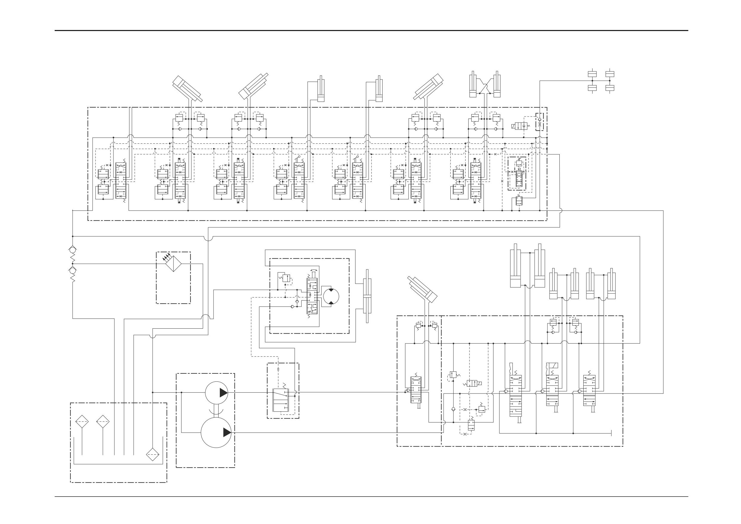
Circuit Schematics
3 - 32
Precision Control (Servo)
24
* (Machines up to serial no. 931159)
22
23
17
18
19
20
21
4
4U
4R
4Q
4P
4N
4M
4L
4K
4J
4H
4T
4G
4F
4E
4D
4C
4B
4A
4S
5
6
7
9
11
12
10
13
14
15
16
3E
3F
3G
3H
8
3M
3Q
2A
1
3N
1A
1B
3A
2
3P
3C
3D
3L
3B
1C
3
A396210
9803/3280
Issue 2*
Section E
Hydraulics
Section E
3 - 33
Circuit Schematics
3 - 33
Precision Control (Servo)
(Machines from January 2003)
T
LS
P
4U
T2
P2
4V
M
T1
4W
11
19
a
4J
4A
b
B1
9
A1
15
1
4K
3
a
4L
4B
7
b
B2
A2
1B
1C
A3
B3
13
22
4M
b
a
3C
a
4C
b
B3
3E
2A
2
A3
23
A2
16
5
B2
a
b
25
3B
3D
a
4D
b
26
14
B4
A4
A1
B1
24
a
b
a
4N
4E
3A
b
B5
A5
8
4P
P2
T2
a
4Q
4F
b
POWER SIDESHIFT
B6
(OPTION)
P
LS
T
45
18
A6
10
HAMMER
6
TP
(OPTION)
HAMMER
HAMMER
(OPTION)
(OPTION)
4R
20
C
P
12
40
P
42
a
4S
4G
41
b
B7
HP
43
T
A7
LP
4T
44
17
21
27
C
4H
T3
4
A403921
9803/3280
Issue 1
Section E
Hydraulics
Section E
3 - 34
Basic System Operation
3 - 34
Hydraulic Circuit Schematic
Precision Control (Servo)
(Machines from January 2003)
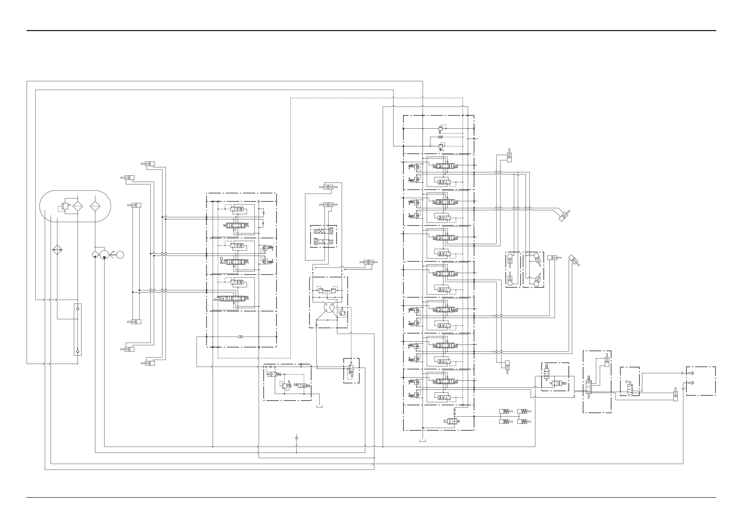
The schematic shows the main system hydraulics for
Precision Control (Servo) machines. For the pilot circuit refer
to relevant pages.
Note: The boom and dipper services are interchanged for
the ISO control pattern.
Component Key:
Small letters on the schematic indicate port markings. Refer
to Technical Data pages at the begining of this section for
more information. Ports A and B are always identified as
service ports (feed and return from respective ram).
1
Tank
5
Hydraulic Oil Cooler
1B
Return Filter
6
Anti Cavitation Check Valve
1C
Suction Strainer
7
Lift Ram R.H.
2
Pump, Main Section
8
Lift Ram L.H.
2A
Pump, Secondary Section
9
Shovel Ram R.H.
3
Loader Valve Block
10
Shovel Ram L.H.
3A
Loader Lift Ram Spool
11
Clam Shovel Ram R.H.
3B
Loader Shovel Ram Spool
12
Clam Shovel Ram L.H.
3C
Clam Shovel Spool
13
Steer Mode Control Valve
3D
Shovel Ram Head Side A.R.V.
14
Steer Unit
3E
Shovel Ram Rod Side A.R.V.
15
AWS Power Track Rod Rams
4
Excavator Valve Block
16
2WS Power Track Rod Ram
4A
Slew Spool
17
Unloader Valve
4B
Boom Spool (Dipper ISO)
18
Priority Valve
4C
Right Stabiliser Spool
19
Stabiliser Ram R.H.
4D
Left Stabiliser Spool
20
Stabiliser Ram L.H.
4E
Dipper Spool (Boom ISO)
21
Hydraclamps (Sideshift Only)
4F
Bucket Spool
22
Boom Ram (Dipper ISO)
4G
Extending Dipper Spool
23
Slew Ram R.H.
4H
Hydraclamp Valve (Sideshift Only)
24
Slew Ram L.H.
4J
Slew A.R.V.
25
Dipper Ram (Boom ISO)
4K
Slew A.R.V.
26
Bucket Ram
4L
Boom Ram Rod Side A.R.V.
27
Extending Dipper Ram
4M
Boom Ram Head Side A.R.V.
4N
Dipper Ram Head Side A.R.V.
4P
Boom Ram Rod Side A.R.V.
4Q
Bucket Ram Head Side A.R.V. (Hammer Only)
Hammer Option:
4R
Bucket Ram Rod Side A.R.V.
40
Hammer Flow Valve
4S
Extending Dipper Ram Rod Side A.R.V.
41
Hammer Selector Valve
4T
Extending Dipper Ram Head Side A.R.V.
42
Hammer Feed Coupling QR
4U
Flow Regulator Valve
43
Hammer Return Coupling QR
4V
Flushing Valve
4W
Load Sense Relief Valve
Power Sideshift Option:
44
Power Sideshift Selector Valve
45
Power Sideshift Ram
9803/3280
Issue 1
Section E
Hydraulics
Section E
3 - 35
Basic System Operation
3 - 35
Hydraulic Circuit Schematic
Precision Control (Servo)
(Machines from January 2003)
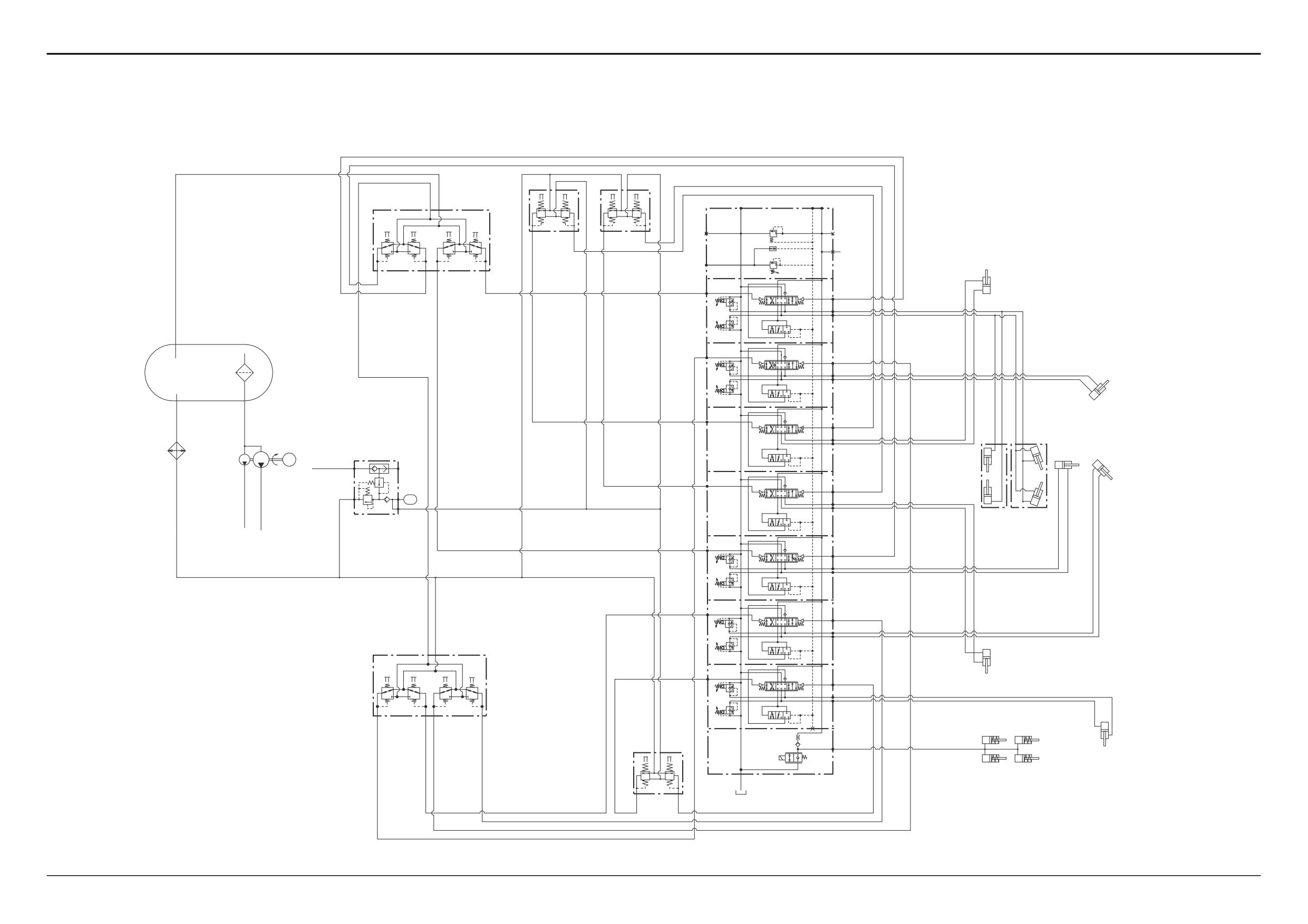
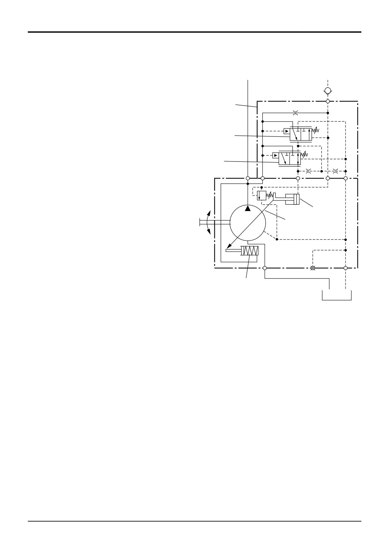
The schematic shows the pilot circuit for Precision Control
(Servo) machines. For the main system hydraulics refer to
relevant pages.
Note: The boom and dipper services are interchanged for
the ISO control pattern.
Component Key:
Small letters on the schematic indicate port markings. Refer
to Technical Data pages at the begining of this section for
more information. Ports A and B are always identified as
service ports (feed and return from respective ram).
4
Excavator Valve Block
19
Stabiliser Ram R.H.
20
Stabiliser Ram L.H.
21
Hydraclamps (Sideshift Only)
22
Boom Ram (Dipper ISO)
23
Slew Ram R.H.
24
Slew Ram L.H.
25
Dipper Ram (Boom ISO)
26
Bucket Ram
27
Extending Dipper Ram
30
Joystick Controller L.H.
31
Servo Pressure Supply Valve
32
Joystick Controller R.H.
33
Stabiliser Control R.H.
34
Stabiliser Control L.H.
35
Footpedal Control (Extending Dipper)
9803/3280
Issue 1
Section E
Hydraulics
Section E
3 - 36
Circuit Schematics
3 - 36
Precision Control (Servo)
(Machines from January 2003)
T
P
T
P
30
P
T
T
LS
P
1
2
1
2
T2
P2
33
34
M
T1
1
2
3
4
19
a
b
B1
A1
a
b
B2
A2
22
a
b
B3
23
A3
31
P1
P2
25
a
b
26
T
B4
PV
A4
24
a
b
B5
A5
a
b
B6
A6
32
P
T
20
a
b
B7
A7
1
2
3
4
21
C
T
P
27
T3
4
1
2
35
A405700
9803/3280
Issue 1
Section E
Hydraulics
Section E
5 - 1
Circuit Descriptions
5 - 1
Hydraulic Pump - Fixed Flow
Component Key:
Single Pump - Operation
A Spur Gear - Idler
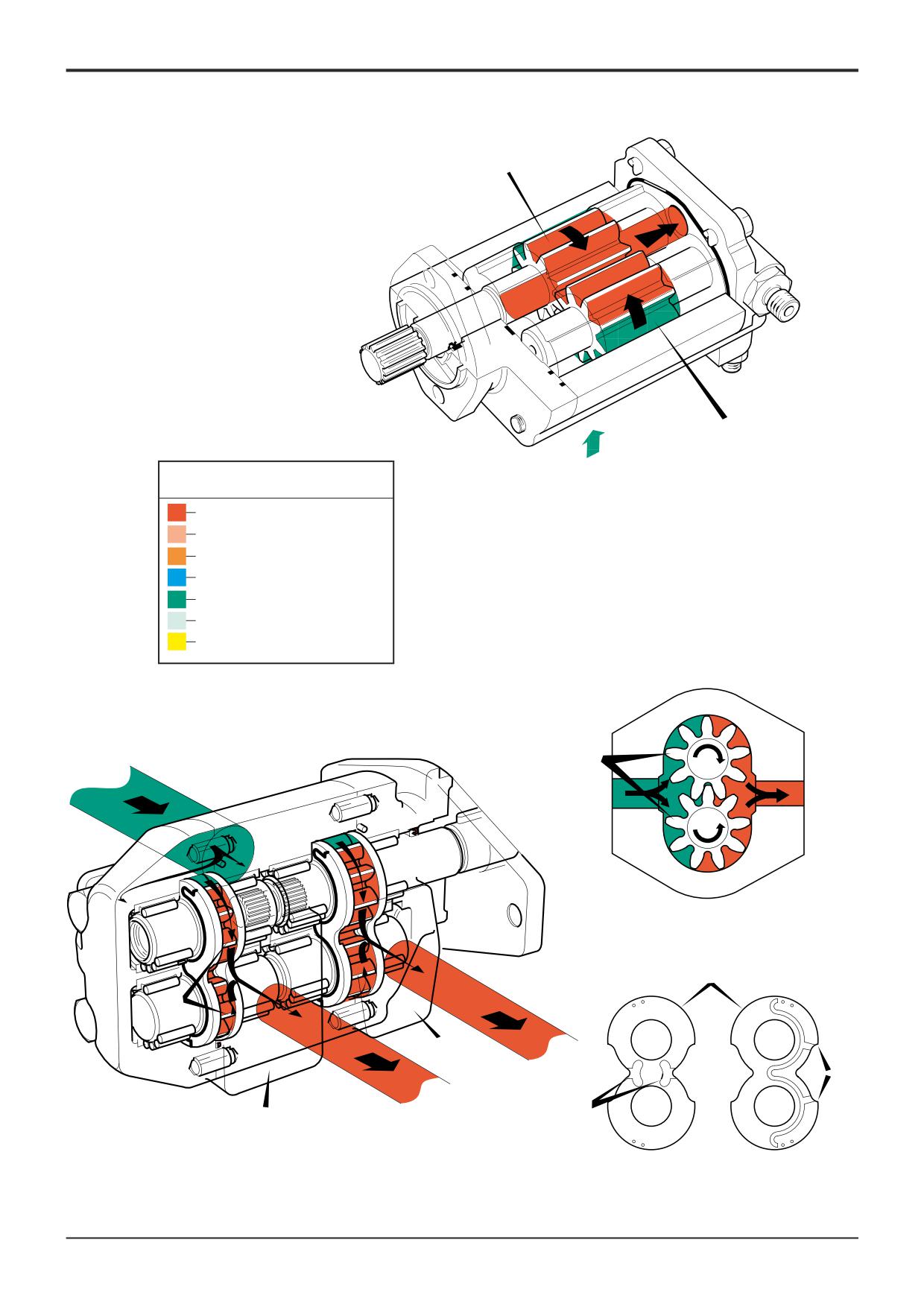
The hydraulic pump is a gear type. The basic principle of the
B Spur Gear - Driven
pump depends on the meshing of the two spur gears A and
C Channel
B, one of which is engine-driven whilst the other is an idler.
D Recess
Oil is picked up on the inlet side of the pump by the gears
P1
Main Section
and carried round between the gear teeth and the pump
P2
Secondry Section
body. As the gears come into mesh the oil is forced through
the pump outlet port.
Lubrication is provided by the hydraulic oil which is directed
around the unit, via special oil ways, by the motion of the
meshing gears.
Double Pump - Operation
Both sections P1 and P2 operate as described below:
The basic principle of the gear pump depends on the mesh-
ing of two spur gears A, one of which is engine driven while
the other is an idler.
Oil is picked up by the gear teeth on the inlet side of the
pump and carried around betwwen the teeth and the pump
body. As the gears come into mesh, the space carrying the
oil is filled by a gear tooth on the mating gear, forcing the oil
out of the space and the through the pump outlet.
The wear plates B are loaded towards the gears by pres-
surised oil which is fed to the backs of the wear plates via
channels C. This ensures that the clearance between the
wear plates and gears is prevented from becoming exces-
sive as outlet pressure rises.
The side of each wear plate that faces the gears has two
recesses D. The recess on the inlet side of the pump assists
the flow of oil into the gear spaces, thus raising the cavitation
threshold of the pump. The recess on the outlet side vents oil
trapped between meshing gear teeth to prevent compres-
sion loads on the bearings.
9803/3280
Issue 1
Section E
Section E
5 - 2
Circuit Descriptions
5 - 2
B
A
Key to Oil Flow & Pressure
Full Pressure
Pressure
Servo
Neutral
Exhaust
Cavitation
Lock Up
A390630
A
B
A
P1
C
D
P2
A396380
9803/3280
Issue 1
Section E
Hydraulics
Section E
5 - 3
Circuit Descriptions
5 - 3
Hydraulic Pump - Variable Flow
Operation
Component Key:
The pump is a variable displacement axial piston type.
P
Pump
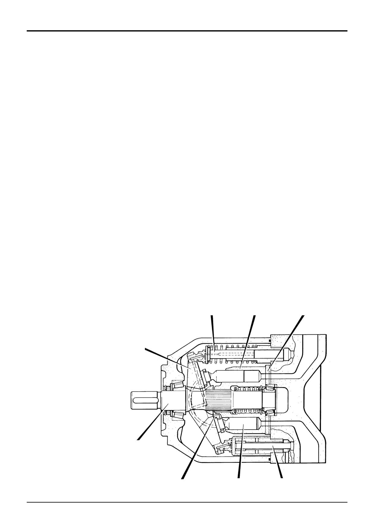
Displacement of oil is achieved by the continuous operation
1
Cylinder Barrel
of nine pistons. Pump fluid output is controlled by a tilting
2
Drive Shaft
cam (swashplate), the angle of which is regulated to ensure
3
Kidney Plate
that only the amount of fluid necessary to satisfy load
4
Axial Piston
conditions is delivered. If a load condition is such that no
5
Swashplate
flow is required, only sufficient fluid for cooling and
6
Shoe Plate
lubrication is provided.
7
Stroking Piston
8
Control Piston
Main components of pump P are a cylinder barrel 1 splined
9
Pressure/Flow Compensator Valve
to a drive shaft 2 which is held against a kidney plate 3.
Contained in the cylinder barrel are the axial pistons 4, each
having an articulated shoe that is in held contact with the
swashplate 5 by an attachment plate 6. The tilting action of
the swashplate is exercised by a stroking piston 7 and a
control piston 8, the latter fed by servo pressure. Fitted to
the pump exterior is the valve block 9 housing the
pressure/flow regulators that provide servo control.
Rotation of the cylinder barrel causes linear movement of the
axial pistons and fluid from the suction port is drawn into the
pump through the kidney plate to fill a developing vacuum
behind the piston. As the cylinder barrel rotates the fluid is
carried from an elongated suction kidney to an elongated
pressure kidney where linear movement starts to return the
piston into the cylinder barrel. Fluid is forced from the pump
through the pressure port.
The stroke length of the pistons and consequently the output
of fluid is directly related to the swashplate angle. The
swashplate is normally held in its maximum displacement
angle by the stroking piston spring and system pressure
7
1
3
inside the stroking piston.
5
2
S271440
6
4
8
9803/3280
Issue 1
Section E
Hydraulics
Section E
5 - 4
Circuit Descriptions
5 - 4
Neutral Circuit Pressure
Pressure Generated by
Operation of a Service
Trapped Oil
Exhaust
13
P
LS
1
2
5
12
11
6
10
T
4
9
A
P
3
8
7
A275730
9803/3280
Issue 1
Section E
Hydraulics
Section E
5 - 5
Circuit Descriptions
5 - 5
Hydraulic Pump - Variable Flow
Pressure/Flow Regulator Valve
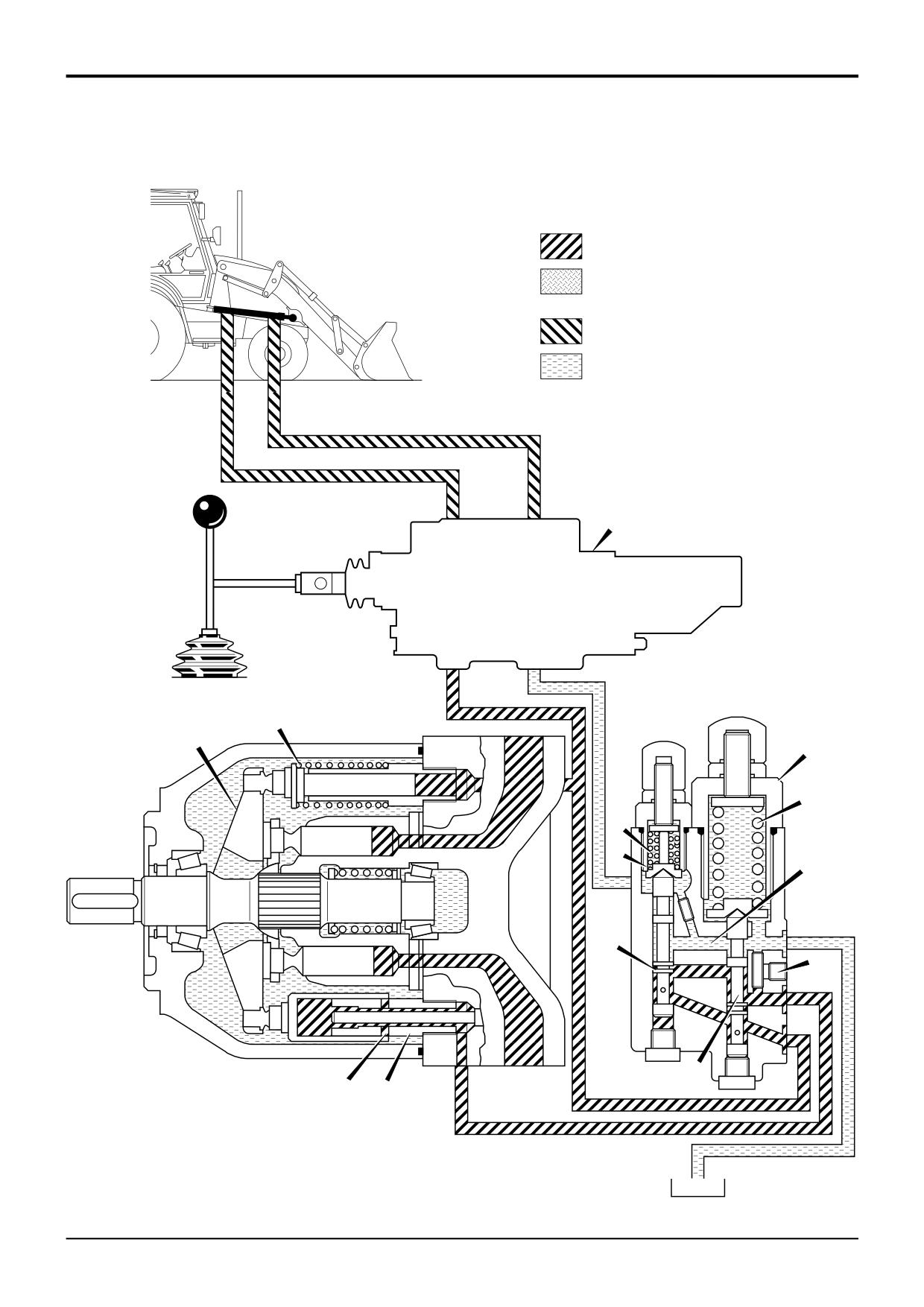
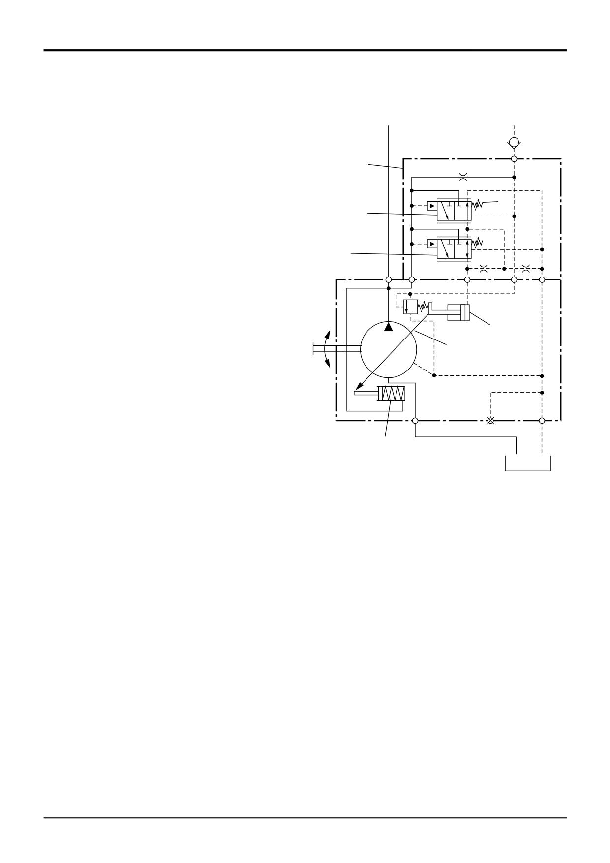
The pressure and flow regulator valve assembly is mounted
5
to the pump. The valve maintains the pump pressure and
flow rate in accordance with demand at the service valve
blocks.
Load Sensing - Stand-by Position
4
Stand-by is when the machine is running but the control
levers are in neutral position, i.e. no implements are being
3
used. There is no pressure or flow demands on the pump,
therefore there will be no pressure signal .
P
A
T
With the engine switched off, spring 1 holds swashplate 2 at
the maximum angle. When the engine is started and the
pump begins to turn, oil begins to flow and pressure builds in
the closed centre hydraulic system.
7
Valve 5 houses a flow regulator spool 4 and pressure
2
regulator spool 3. Pressure which is building in the closed
centre system is sensed at port P of the regulator valve. The
increasing pressure pushes flow compensating spool 4 up
against its spring 6. This movement creates a flow path from
port P to port A. Oil now flows from the flow regulator valve
(via port A) to swashplate control piston 7.
The control piston now moves the swashplate 2 towards its
minimum angle. As the piston moves towards its full travel
1
position, cross-drilled holes 8 are uncovered allowing oil to
drain.
A275760
The cross-drilled holes limit the travel of the control piston -
when the holes are exposed, pump flow is insufficient to
make up for leakage through the holes and maintain the
pressure behind the control piston. Therefore the piston
moves back to partially cover the cross holes thus
maintaining enough flow to cater for normal system leakage
whilst establishing a system stand-by pressure (see
Technical Data for pressure).
9803/3280
Issue 1
Section E
Hydraulics
Section E
5 - 6
Circuit Descriptions
5 - 6
Neutral Circuit Pressure
Pressure Generated by
Operation of a Service
Trapped Oil
Exhaust
13
P
LS
1
2
5
12
11
6
10
T
4
9
A
P
3
8
7
A275740
9803/3280
Issue 1
Section E
Hydraulics
Section E
5 - 7
Circuit Descriptions
5 - 7
Hydraulic Pump - Variable Flow
Pressure/Flow Regulator Valve
Load Sensing - Maximum Flow
5
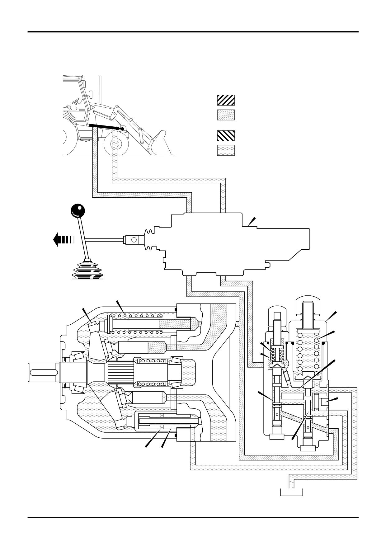
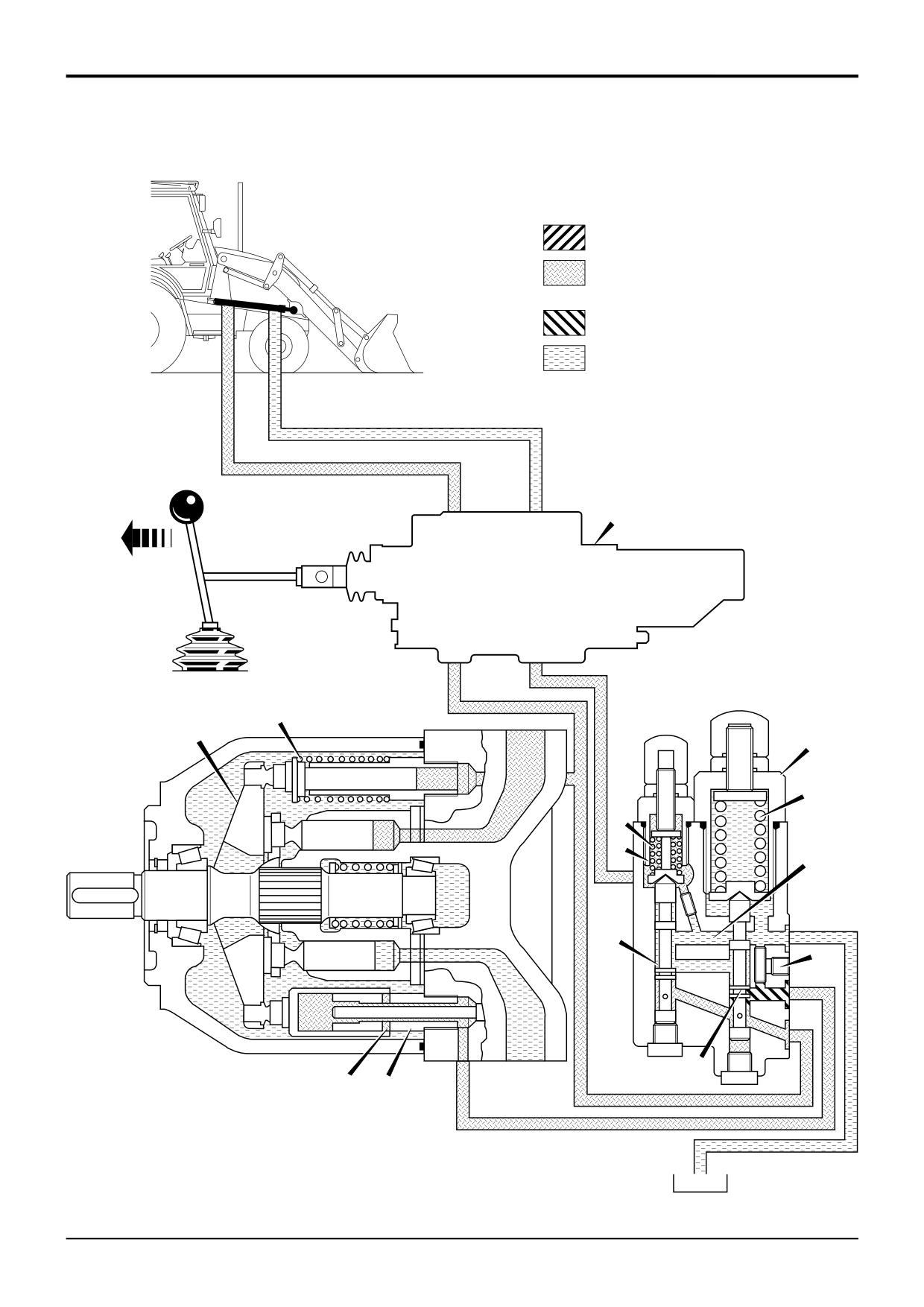
When a service is operated, the signal pressure from the
loader (or backhoe) valve 13 increases. The increase in signal
pressure combined with the force of spring 6 moves spool 4
6
down. Oil in control piston 7 is allowed to drain back to the
4
tank via restrictor 9 and passage 10.
The force of spring 1 is now sufficient to increase the angle
3
of swashplate 2. The increased angle of the swashplate
increase the output of the pump.
P
A
T
The pump output pressure will continue to increase,
eventually the pressure will move flow regulating spool 4
against the force of spring 6 and the signal pressure in cavity
11. Pump output pressure is now sent to control piston 7 via
7
port A. Control piston 7 will overcome the force of spring 1.
The pump swashplate angle decreases and therefore the
2
pump outlet decreases. Eventually the pressure in the load
sense line and the force of spring 6 will move spool 4 down
and the ‘metering’ cycle starts again.
The up and down movement of the spool 4 keeps the
pressure on both ends of the spool equal. Spring 6 is
equivalent to 20 bar (290 lbf/in2), therefore the pump
pressure should be this amount greater than the signal
pressure (except when at maximum pressure - see Load
1
Sensing - Maximum Pressure (no flow).
A275770
9803/3280
Issue 1
Section E
Hydraulics
Section E
5 - 8
Circuit Descriptions
5 - 8
Neutral Circuit Pressure
Pressure Generated by
Operation of a Service
Trapped Oil
Exhaust
13
P
LS
1
2
5
12
11
6
10
T
4
9
A
P
3
8
7
A275750
9803/3280
Issue 1
Section E
Hydraulics
Section E
5 - 9
Circuit Descriptions
5 - 9
Hydraulic Pump - Variable Flow
Pressure/Flow Regulator Valve
Load Sensing - Maximum Pressure (no flow)
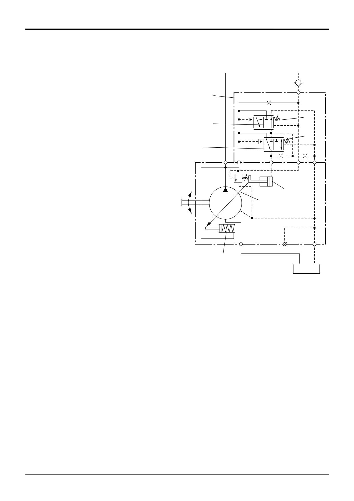
5
When a service ram reaches the end of its stroke or the
service meets resistance (for instance tearing out), the signal
pressure from the loader (or backhoe) valve 13 will increase
6
to the same pressure as pump output pressure.
4
The force of spring 6 is sufficient to move spool 4 down. The
12
pressure in the system is also sufficient to move spool 3 up
3
against the force of spring 12, this creates a connection from
the pump outlet to control piston 7 via port A.
P
A
T
Control piston 7 moves thus decreasing the angle of
swashplate 2. Pump output flow now decreases whilst the
system pressure is maintained at maximum setting. There is
now no flow but maximum system pressure.
7
2
1
A275780
9803/3280
Issue 1
Section E
Hydraulics
Section E
6 - 1
Circuit Descriptions
6 - 1
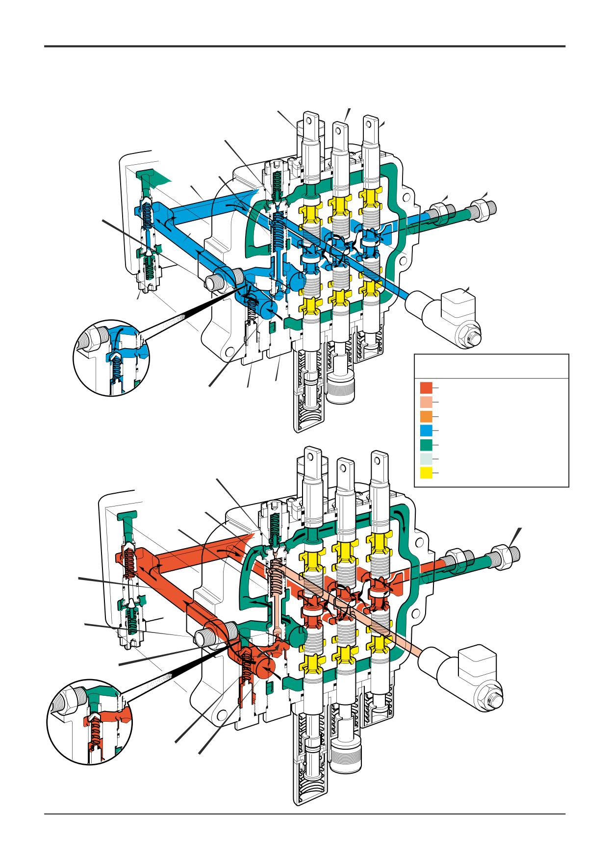
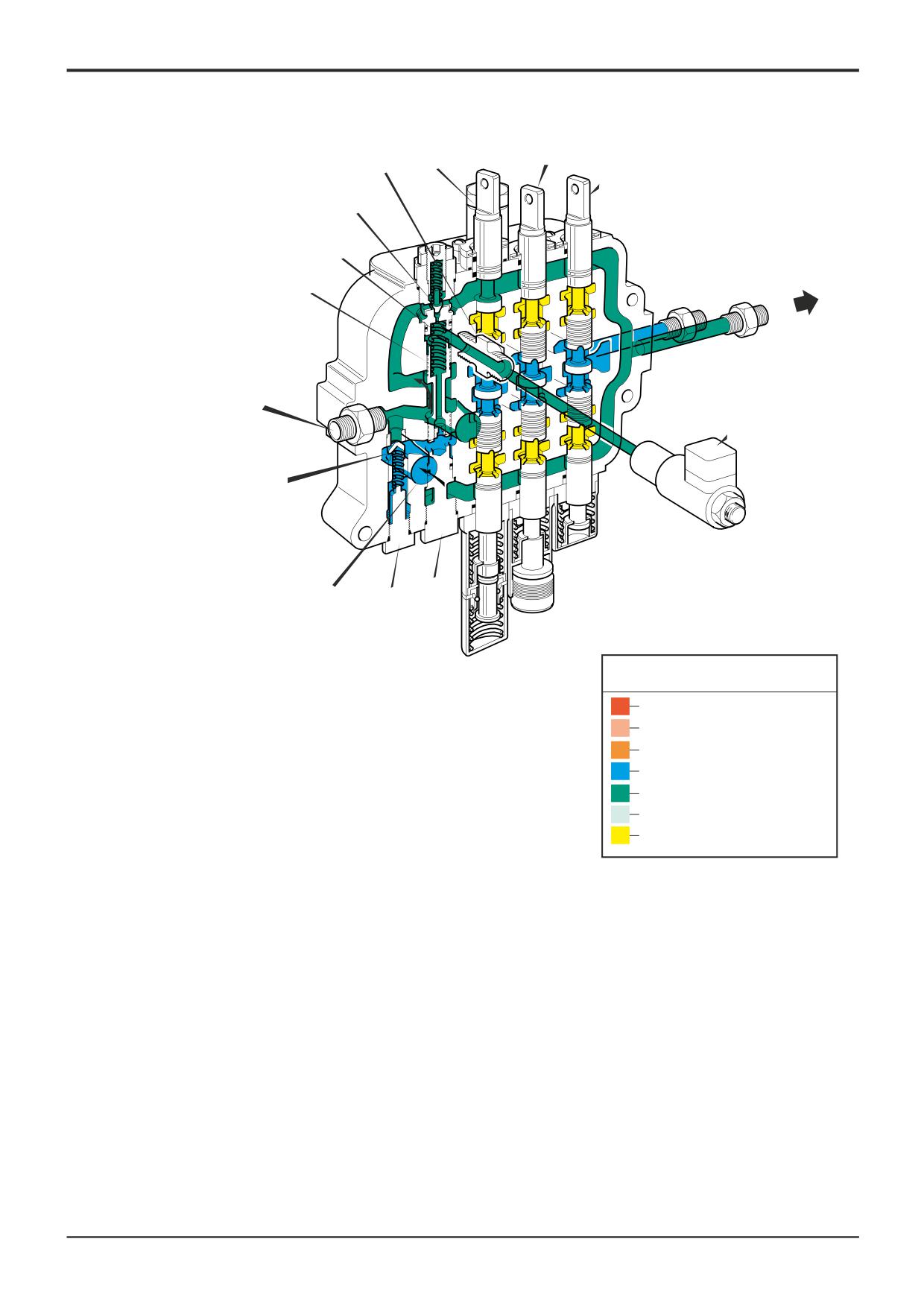
Loader Valve - Neutral Circuit
Component Key:
The loader valve is mounted on the chassis frame, right
hand side (when viewed from the rear).
B
Parallel gallery
C
Gallery
It includes the lift ram spool 3C, shovel ram spool 3D and
D
Drilling
auxiliary spool 3E. Linkage rods connect the spool ends to
T
Tank Port
the control levers.
1A
Pump Inlet (section P1)
1B
High Pressure Carry Over
In neutral circuit hydraulic oil from the pump section P2
1C
Pump Inlet (section P2)
enters the loader valve at 1C via the steering priority valve.
3B
Main Relief Valve
On entering the valve block, oil flows around the waisted
3C
LIft Ram Spool
section of the unloader valve 3L, past check valve 3N and
3D
Shovel Ram Spool
joins the flow from pump section P1.
3E
Auxiliary Spool
3L
Unloader Valve Spool
Oil from pump section P1 enters the loader valve at 1A.
3M Unloader Pilot Valve
3N Check Valve
Combined oil flow from P1 and P2 passes the main relief
3P
Spring Cavity
valve (MRV) 3B and fills the parallel gallery B. From the
3Q
Solenoid Valve
parallel gallery the oil flows around the waisted central
portions of spools 3C, 3D and 3E (all in neutral position) and
flows on to feed the excavator valve via high pressure carry
over line 1B.
Pressure in inlet gallery C is sensed by pilot valve 3M via the
bore of spool 3L. At pressures below the setting of the
unloader valve, both pilot valve 3M and spool 3L remain
closed.
Loader Valve - Unloader Operation
Unloader spool operation protects the engine from being
overloaded if a service is being worked particularly hard, for
example when using the excavator to tear out. It does this
by dumping the oil from the pump section P2 to tank,
allowing engine power to be applied fully to the main pump
section P1.
If the pressure in the inlet gallery C rises to the setting of the
pilot valve 3M, this valve will open, allowing oil in spring
cavity 3P to escape more quickly than it can be replaced by
oil entering through the small drilling D.
This creates a pressure differential between the spring cavity
3P and gallery C. Higher pressure in gallery C acts on the
face of spool 3L causing the spool to be moved off its seat.
Oil entering the valve block from pump section P2 now flow
directly to tank T.
High pressure in gallery C also holds check valve 3N firmly
closed, preventing oil from pump section P1 from also being
dumped.
When pressure in inlet gallery C falls, for example if the
excavator has stopped tearing out, pilot valve 3M will close.
This means oil in spring cavity 3P will be at the same
pressure as oil in gallery C, spring pressure will move spool
3L back onto its seat, closing pump section P2 connection
to tank.
9803/3280
Issue 1
Section E
Section E
6 - 2
Circuit Descriptions
6 - 2
3D
3C
3E
3M
3L
B
1B T
1C(P2)
C
3Q
3B
Key to Oil Flow & Pressure
Full Pressure
3N
3J
1A(P1)
Pressure
Servo
A401150
Neutral
Exhaust
Cavitation
3M
Lock Up
A390630
3P
T
3L
C
P2
D
3N P1
A401160
9803/3280
Issue 1
Section E
Section E
6 - 3
Circuit Descriptions
6 - 3
3D
W
3C
3E
3M
3P
3L
T
1C(P2)
3Q
C
1A(P1)
3N
3J
A401170
Key to Oil Flow & Pressure
Full Pressure
Pressure
Servo
Neutral
Exhaust
Cavitation
Lock Up
A390630
9803/3280
Issue 1
Section E
Hydraulics
Section E
6 - 4
Circuit Descriptions
6 - 4
Loader Valve
Component Key:
- Hydraulic Speed Control (HSC)
B Parallel gallery
C Gallery
Solenoid valve 3Q allows the operator to control the
D Drilling
unloader spool movement (to dump flow from the hydraulic
T Tank Port
pump section P2) using a switch. There are two main
1A Pump Inlet (section P1)
applications for this operation:
1B High Pressure Carry Over
1C Pump Inlet (section P2)
1
More tractive force can be applied to the loader end
3B Main Relief Valve
when entering a stock pile. This is because more power
3C LIft Ram Spool
is available from the engine as flow from pump section
3D Shovel Ram Spool
P2 is being dumped directly to tank.
3E Auxiliary Spool
3L Unloader Valve Spool
2
More power can be made available from the engine
3M Unloader Pilot Valve
whilst the machine is travelling on the highway. Again,
3N Check Valve
this is because flow from pump section P2 is being
3P Spring Cavity
dumped directly to tank.
3Q Solenoid Valve
When the solenoid valve 3Q is de-energised its spool is
moved by spring pressure. This spool movement makes a
connection from the unloader spool chamber 3P to tank.
Because the unloader chamber is now connected to tank,
and so at exhaust pressure, pressure in gallery C (neutral
shown) acts on the face of unloader spool 3L causing the
spool to be moved off its seat. Oil entering the valve block
from pump section P2 now flows directly to tank.
When solenoid valve 3Q is energised its spool closes the
connection from the unloader valve spool chamber to tank.
Spool 3L is once again controlled by system pressure.
9803/3280
Issue 1
Section E
Hydraulics
Section E
6 - 5
Circuit Descriptions
6 - 5
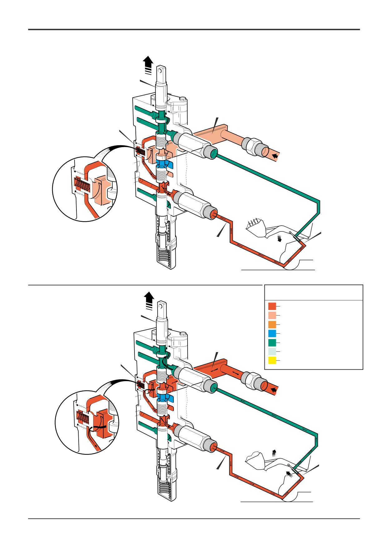
Loader Valve - Load Hold Check Valves
Component Key:
Operation 1
1A Pump Inlet
The illustration shows 'arms raise' being selected by the lift
B Parallel Gallery
ram spool 3C.
D Service Line
3C Lift Ram Spool
The weight of the loaded shovel, as indicated by the arrows,
3J Load Hold Check Valve
produces a higher pressure in service line D than in the
33
Lift Ram
parallel gallery B.
34
Lift Ram
This pressure differential causes load hold check valve 3J to
close, thus preventing the load from dropping.
Operation 2
As the neutral circuit has been blocked by the central land of
the selected spool 3C, the pressure in parallel gallery B
increases until it is greater than that in service line D.
At this point, load hold check valve 3J opens, allowing oil to
flow from the parallel gallery into the service line and operate
the lift rams 33 and 34.
9803/3280
Issue 1
Section E
Section E
6 - 6
Circuit Descriptions
6 - 6
3C
B
3J
1A
33
34
D
A396410
Key to Oil Flow & Pressure
Full Pressure
Pressure
3C
Servo
Neutral
Exhaust
B
Cavitation
3J
Lock Up
A390630
1A
33
34
D
A396420
9803/3280
Issue 1
Section E
Section E
6 - 7
Circuit Descriptions
6 - 7
3C
D
B
3J
1A
C
E
33
34
A396390
Key to Oil Flow & Pressure
Full Pressure
3C
Pressure
Servo
Neutral
Exhaust
A
Cavitation
Lock Up
A390630
A
33
34
A396400
9803/3280
Issue 1
Section E
Hydraulics
Section E
6 - 8
Circuit Descriptions
6 - 8
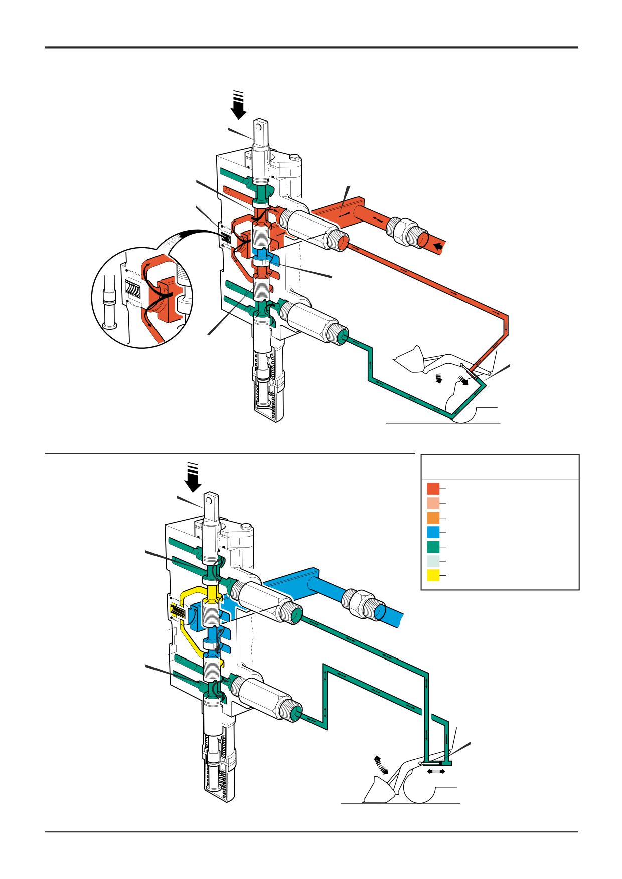
Loader Valve
Arms Lower
Component Key:
A Spool Waists
When a spool is selected as shown at 3C, the central land of
B Parallel Gallery
the spool C blocks the neutral circuit. Oil from the pump,
C Central Land
entering at 1A, is diverted into the parallel gallery B, opens
D Spool Waist
the load hold check valve 3J, and flows around the waisted
E Lower Waist
section of the spool D and out to the rod side of lift rams 33
1A Pump Inlet
and 34.
3C Lift Ram Spool
3J Load Hold Check Valve
The lower land of the selected spool E blocks the flow from
33
Lift Ram
the parallel gallery to the head side port and oil returning
34
Lift Ram
from the rams is diverted into the exhaust gallery.
Float
The float facility is provided to allow the arms to move up
and down so that the shovel can follow the surface contours
as the machine is driven over uneven ground.
This is achieved by moving the lift spool 3C down beyond
'arms lower' into the 'float' detent, when the feed from the
parallel gallery to the service ports is blocked and the neutral
circuit is re-opened. Both service ports are connected to
exhaust via the spool waists A.
Oil can then be displaced from either end of the lift rams 33
and 34 into the exhaust gallery, allowing the rams to open
and close as required.
9803/3280
Issue 1
Section E
Hydraulics
Section E
6 - 9
Circuit Descriptions
6 - 9
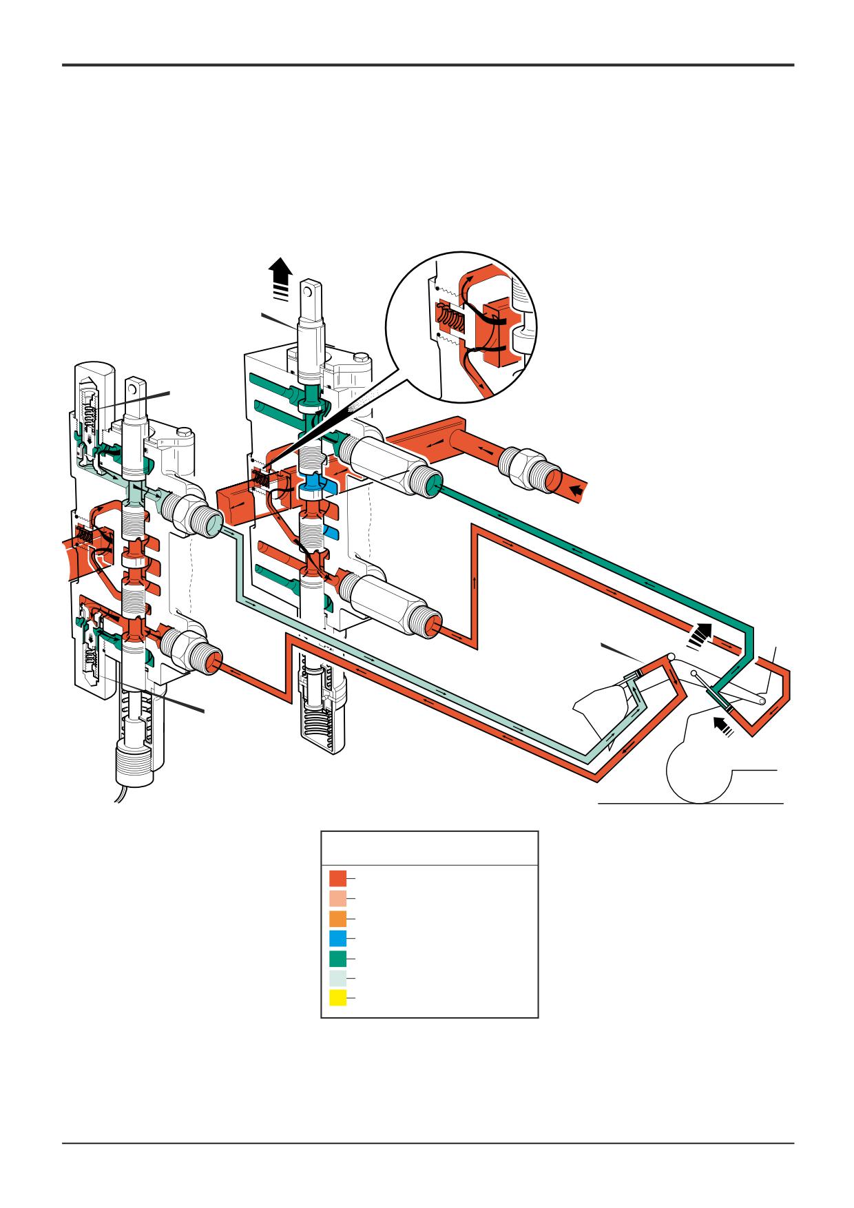
Loader Valve - A.R.V. Operation
Component Key:
Under normal operating conditions, with the shovel in the
'carry' position, the mechanical linkage keeps the shovel
1A Pump Inlet
level as the arms are raised, to prevent spillage of the load.
3C Lift Ram Spool
3D Shovel Ram Spool
If, as illustrated, the shovel is fully tipped when the arms are
3F ARV - Head Side
being raised, the shovel is unable to tip further, producing
3G ARV - Rod Side
back pressure in the head side of the shovel rams 31 and
31
Shovel Ram
32 and cavitation in the rod side.
32
Shovel Ram
As the arms continue to rise, the back pressure increases
until it reaches the setting of A.R.V. 3F. This A.R.V. then
opens, allowing the excess back pressure to be dumped to
exhaust and prevent the rams and linkage from being
damaged.
The rod side A.R.V. 3G senses a higher pressure in the
exhaust gallery than in the service port and therefore opens
to allow exhaust oil to overcome the cavitation.
9803/3280
Issue 1
Section E
Section E
6 - 10
Circuit Descriptions
6 - 10
3C
3G
1A
32
31
3F
A396370
Key to Oil Flow & Pressure
Full Pressure
Pressure
Servo
Neutral
Exhaust
Cavitation
Lock Up
A390630
9803/3280
Issue 1
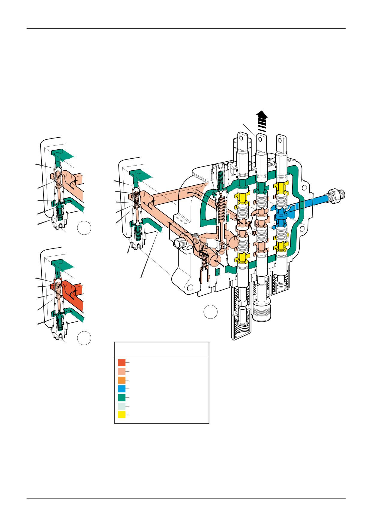
Section E
Section E
6 - 11
Circuit Descriptions
6 - 11
3D
A
B
D
E
H
1A
A
D
F
G
C
2
3B
D
1A
E
A
1A
C
1
F
A401180
3
Key to Oil Flow & Pressure
Full Pressure
Pressure
Servo
Neutral
Exhaust
Cavitation
Lock Up
A390630
9803/3280
Issue 1
Section E
Hydraulics
Section E
6 - 12
Circuit Descriptions
6 - 12
Main Relief Valve (MRV) - Operation
The main relief valve (M.R.V.) 3B, situated in the loader valve
Component Key:
block, provides control of both loader and excavator
pressures.
A
Main Plunger
B
Valve Seat
1
Valve at Rest
C
Spring
D
Chamber
The illustration 1 shows a loader service selected by spool
E
Drilling
3D causing pressure to rise in the service line and back
F
Pilot Valve
through the loader valve to the pump via line 1A. The service
G
Spring
is operating under light load and the pressure is not
H
Exhaust Gallery
sufficient to cause any response in the M.R.V.
1A
Pump Inlet
3B
Main Relief Valve
The main plunger A is held on its seat B by the combined
3D
Shovel Ram Spool
effect of spring C and the pump pressure which enters
chamber D through the small drilling E. Pump pressure
outside the chamber is not high enough to lift the plunger off
its seat.
2
Pilot Valve Opens
If, as shown in view 2, pump pressure rises high enough to
force the pilot valve F from its seat (against spring G), the
pressure in chamber D is vented into the exhaust gallery H.
Unless the pressure continues to rise, plunger A will remain
on its seat.
3
Valve Moves off its seat
In view 3, pump pressure at 1A has risen to the setting of
the main relief valve but pressure in chamber D has not risen
because the seat orifice of pilot valve F is larger than small
drilling E and oil is unable to fill the chamber as quickly as it
is being exhausted.
Pressure acting on the upper faces of main plunger A is
therefore greater than the combined force of spring C and
the pressure in chamber D. The plunger then moves off its
seat, allowing pressure to be released to the exhaust gallery.
As the pump pressure decreases, the pilot valve is able to
reseat and pressure in chamber D assists spring C to force
the main plunger A back onto its seat.
9803/3280
Issue 1