JCB 3CX, 4CX, 214e, 214, 215, 217 & VARIANTS Backhoe Loader. Service Manual - page 12
Section E
Section E
Hydraulics
2 - 11
Technical Data
2 - 11
Relief Valve Pressures
Auxiliary Valve - Fixed Flow
bar
kgf/cm2
lbf/in2
Extradig Ram Head Side
138 - 145
141 - 148
2000 - 2100
Extradig Ram Rod Side
207 - 214
211 - 218
3000 - 3100
Jaw Bucket Ram Head Side
138 - 145
141 - 148
2000 - 2100
Jaw Bucket Ram Rod Side
207 - 214
211 - 218
3000 - 3100
Knuckle Ram Head Side
138 - 145
141 - 148
2000 - 2100
Knuckle Ram Rod Side
207 - 214
211 - 218
3000 - 3100
Hammermaster
207 - 214
211 - 218
3000 - 3100
Power Sideshift (both)
207 - 214
211 - 218
3000 - 3100
Hand Held Tools
138 - 150
141 - 153
2000 - 2200
Component Key:
1
Auxiliary Spool
2
Inlet port
2
Outlet port
3
Auxiliary relief valve
4
High pressure carry-over (HPCO) port
7
Service ‘A’ ports
8
Service ‘B’ ports
Weight:
TBA kg (TBA lbs)
9803/3280
Issue 1
Section E
Section E
Hydraulics
2 - 13
Technical Data
2 - 13
Smooth Ride System
System Type
A piston type accumulator operates as a liquid spring
absorbing displaced fluid from the lift rams. Selectable
from a switch in the cab.
Charging Gas
Air Free Dry Nitrogen
Accumulator Capacity
1.0 litre (58 cu/in)
Accumulator Weight
4.4 kg (9.75 lb)
Accumulator Charge Pressure
As a general guide for given shovel weights (loaded) see below:-
bar
kgf/cm2
lbf/in2
Shovel weights up to 700 kg (1540 lb)
13.8
14
200
Shovel weights 700 kg to 950 kg (1540 - 2100 lb)
19
19.4
275
Shovel weights over 950 kg (2100 lb)
24
24.5
350
Note: Replacement accumulators will only be supplied in an uncharged, non pressureised condition to meet Health and
Safety/Airfreight hazardous goods requirements.
9803/3280
Issue 1
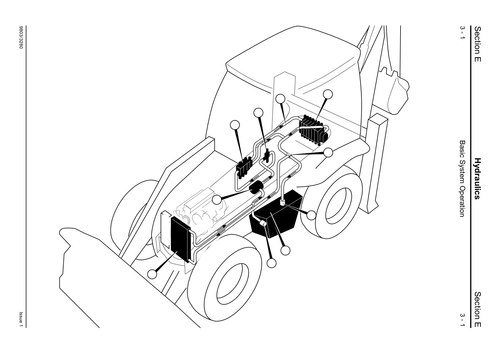
Component Location
4
1B
7
3
13
P
6
T
1C
26
A401400
Component Location
Neutral Circuit Description
Component Key:
Fixed Flow - Single Pump
T
Hydraulic Tank
P
Hydraulic Pump (engine driven)
1B Hose - High Pressure Carry Over
Oil is drawn from the hydraulic tank T by the single
3
Loader Valve Block
stage hydraulic pump P. The pump is mounted on
4
Excavator Valve
the rear of the gearbox and is engine driven via a
6
Return Line Filter (inside hydraulic tank)
driveshaft.
7
Steer Circuit Priority Valve
13
Return Line Check Valve
Pressurised oil from the pump flows to steering
26
Hydraulic Oil Cooler
priority valve 7, and in neutral circuit flows through
the priority valve to the loader valve 3.
From the loader valve neutral gallery, oil flows via a
high pressure carry-over line 1B to the excavator
valve 4.
Some of the exhaust oil flows directly back to the
tank through an in-tank filter 6, and some of the
exhaust oil returns to tank via the hydraulic oil
cooler 26.
To help prevent excavator dipper ram and loader lift
ram cavitation, there is a check valve 13 fitted to
the return line. The check valve raises
approximately 5 bar (75 lbf/in2) of pressure in the
line, which improves the operation of the respective
anti-cavitation valves.
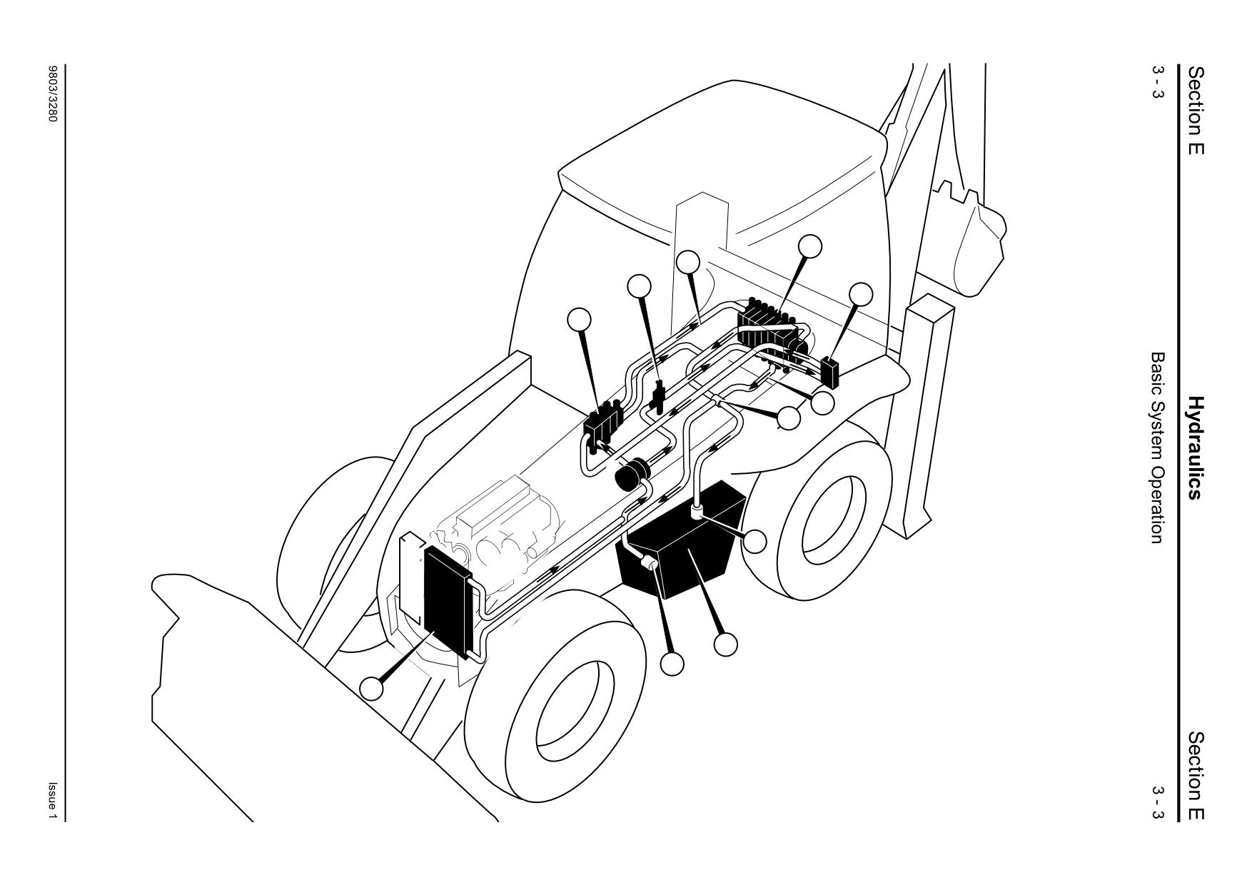
Component Location
4
1B
7
5
3
5
62
13
P2
P1
6
T
1C
26
A401420
Component Location
Neutral Circuit Description
Component Key:
Fixed Flow - Double Pump
T Hydraulic Tank
P1 Hydraulic Pump (main section)
Oil is drawn from the hydraulic tank T by the
P2 Hydraulic Pump (secondary section)
hydraulic pump. The pump has two sections, P1
1B Hose - High Pressure Carry Over
and P2.
3
Loader Valve Block
4
Excavator Valve
The hydraulic pump is mounted on the rear of the
5
Auxiliary Valve
gearbox and is driven by the engine via a
6
Return Line Filter (inside hydraulic tank)
driveshaft.
7
Steer Circuit Priority Valve
13
Return Line Check Valve
Oil from the larger section P1 flows direct to the
26
Hydraulic Oil Cooler
loader valve 3. Oil from pump section P2, flows to
62
Hydraclamp exhaust hose
steering priority valve 7, and in neutral circuit flows
through the priority valve to the auxiliary valve 5
and then to join the flow from P1 at the loader
valve.
From the loader valve neutral gallery, oil flows via a
high pressure carry-over line 1B to the excavator
valve 4.
Some of the exhaust oil flows directly back to the
tank through an in-tank filter 6, and some of the
exhaust oil returns to tank via the hydraulic oil
cooler 26.
To help prevent excavator dipper ram and loader lift
ram cavitation, there is a check valve 13 fitted to
the return line. The check valve raises
approximately 5 bar (75 lbf/in2) of pressure in the
line, which improves the operation of the respective
anti-cavitation valves.
On sideshift machines only, hydraclamp exhaust
hose
62 is fitted. The hose connects the
hydraclamp spool directly into the exhaust circuit.
This prevents the clamps from ‘locking-up’ when
the sideshifting operation is required.
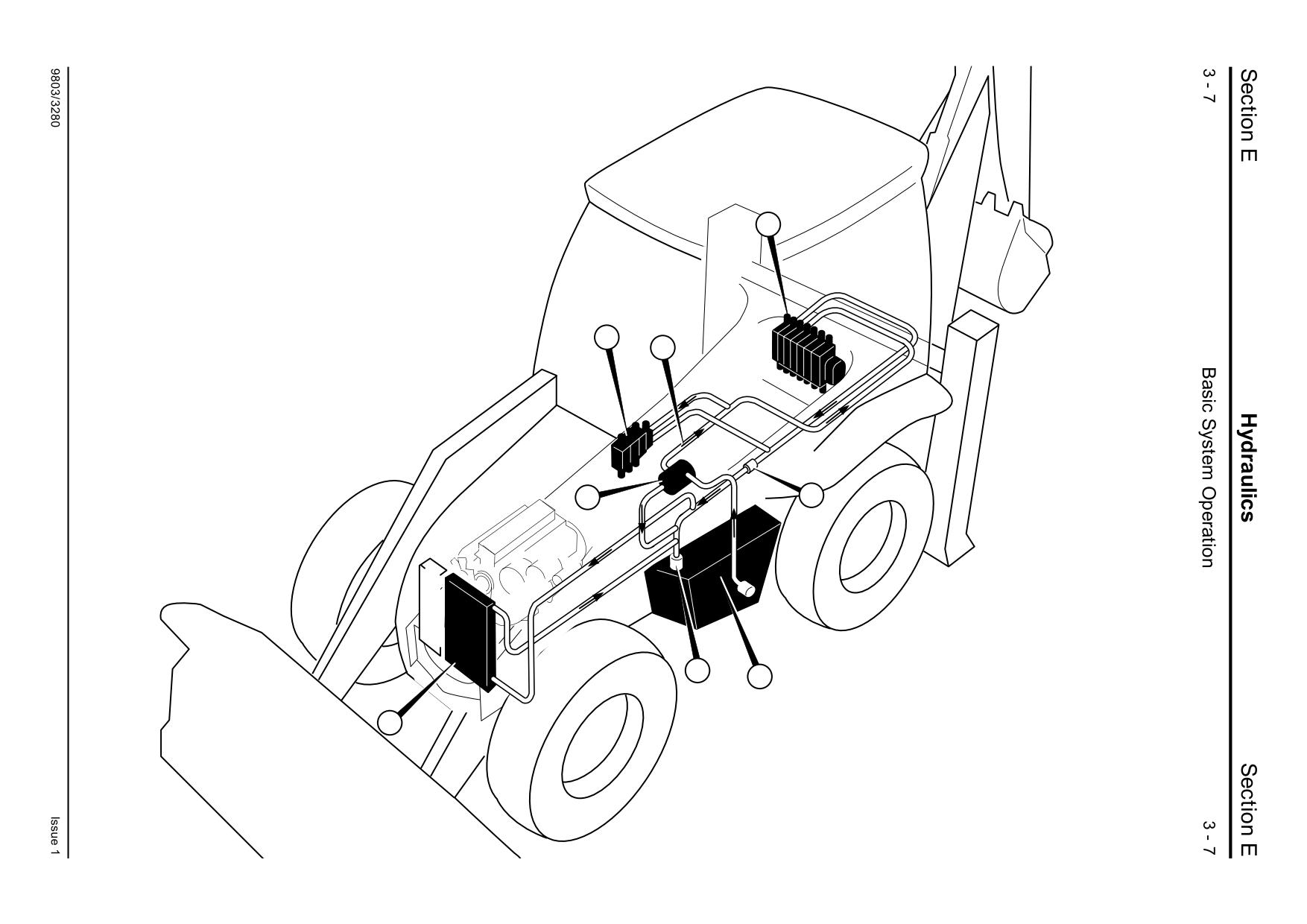
Component Location
4
3
1A
5
P
13
6
T
26
A401430
Component Location
Neutral Circuit Description
Component Key:
Variable Flow
T
Hydraulic Tank
The variable flow displacement pump P is mounted
P
Hydraulic Pump (engine driven)
on the rear of the gearbox and is engine driven via
1A Pump Outlet Pipe/Hose
a driveshaft.
3
Loader Valve Block
4
Excavator Valve
With variable flow hydraulics, there is no ‘neutral’
6
Return Line Filter (inside hydraulic tank)
circuit. This is because the pump P operates on a
13
Return Line Check Valve
demand signal from the services (see Circuit
26
Hydraulic Oil Cooler
Descriptions, Hydraulic Pump - Variable Flow
Operation). If there is no demand, then the pump
does not draw oil from the tank and no oil is
delivered, there is no pump flow in the neutral
position.
When a service is selected, the pump senses the
demand and oil is drawn from the hydraulic tank T.
Pressurised oil from the pump flows to the loader
valve 3 and/or the excavator valve 4 via hose and
pipe assembly 1A.
The loader valve 3 is fitted with a priority inlet
manifold, oil entering the loader valve is distributed
to the (priority) steer circuit and/or the loader
services as required (see Circuit Descriptions,
Loader Valve - Variable Flow Operation).
Some of the exhaust oil flows directly back to the
tank through an in-tank filter 6, and some of the
exhaust oil returns to tank via the hydraulic oil
cooler 26.
To help prevent excavator dipper ram and loader lift
ram cavitation, there is a check valve 13 fitted to
the return line. The check valve raises
approximately 5 bar (75 lbf/in2) of pressure in the
line, which improves the operation of the respective
anti-cavitation valves.
Section E
Hydraulics
Section E
3 - 10
Basic System Operation
3 - 10
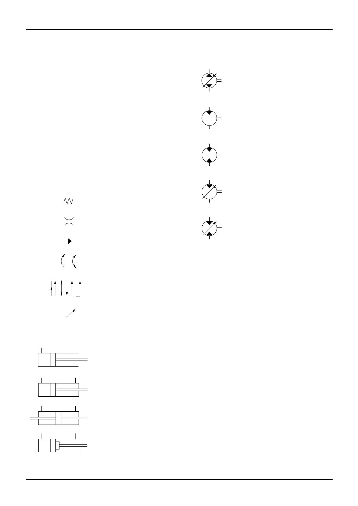
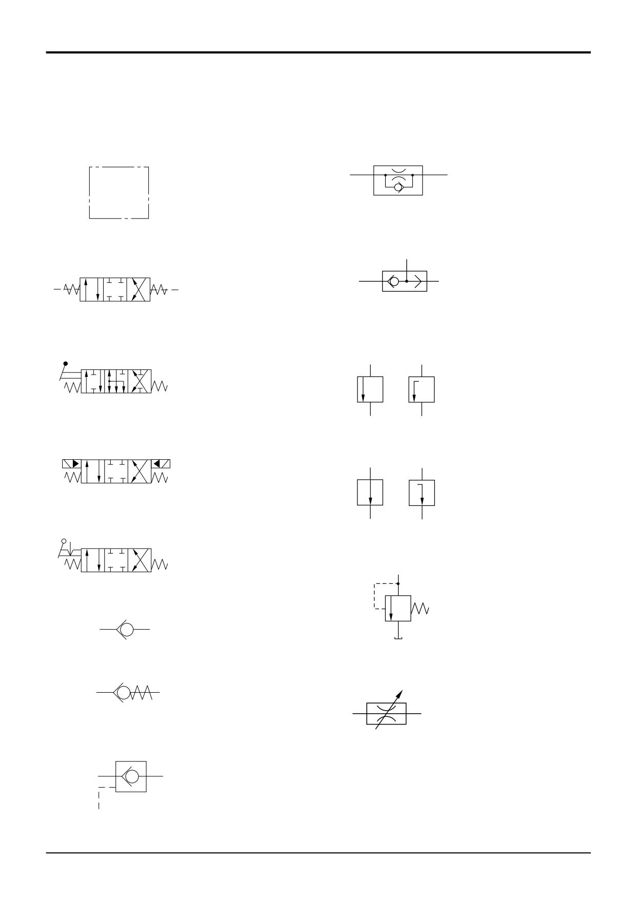
Introduction to Hydraulic Schematic
Pumps & Motors
Symbols
Complex hydraulic components and circuits can be
Variable capacity pump
described to the engineer by using graphical symbols. The
two directions of flow
following pages illustrate and give a brief description for
some of the more common symbols used.
There are many symbols in use and it would be impossible
to include them all here. However it should be noted that
Fixed capacity motor
most are only variations or refinements on the basic
one direction of flow
principles explained here. If more detailed information is
required you are recommended to obtain a copy of BS2917
or IS01219.
Fixed capacity motor
Once familiar with the symbols, the engineer can use
two directions of flow
hydraulic circuit diagrams as an aid to fault finding. It will be
possible to see the complete hydraulic circuit and decipher
the relationship between hydraulic components.
General (Basic & Functional Symbols)
Variable capacity motor
one direction of flow
Spring
Flow restriction
affected by viscosity
Variable capacity motor
two directions of flow
Direction of flow
Indication of rotation
Indication of direction
and paths of flow
A189660
Variable control
Rams
Single acting
Double acting
Double ended
Double acting with
damping at rod area end
A189670
A189680
9803/3280
Issue 1
Section E
Hydraulics
Section E
3 - 11
Basic System Operation
3 - 11
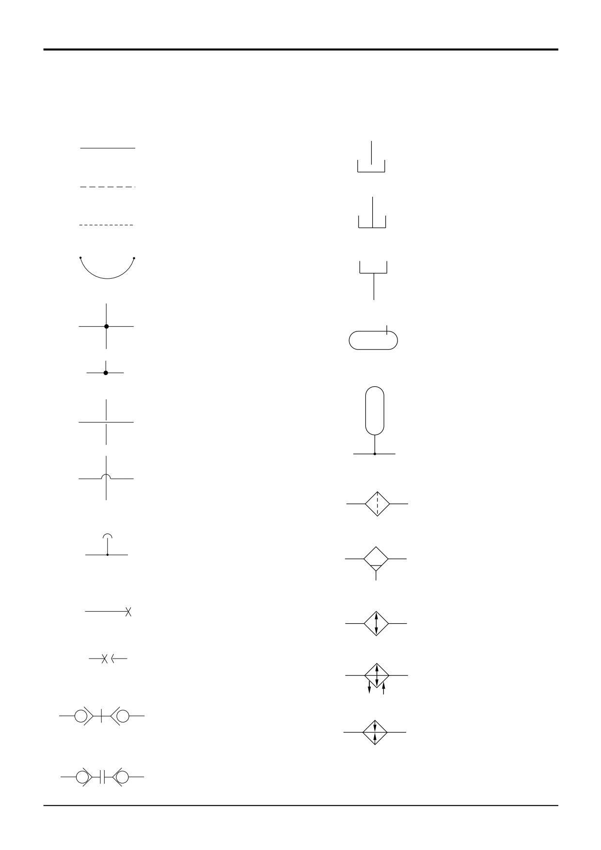
Introduction to Hydraulic Schematic
Symbols (cont'd)
Control Valves
One way restrictor
Used to enclose several
valves indicating that they
are supplied as one unit
High pressure selector
3-Position, 4-Port
(shuttle valve)
spring centred pilot
operated valve
3-Position, 6-Port
Throttling orifice -
spring centred hand
normally closed
operated valve
3-Position, 4-Port
spring centred solenoid &
pilot pressure operated valve
Throttling orifice -
normally open
3-Position, 4-Port
spring centred detent
hand operated valve
Relief valve
Non - return valve
Non - return valve with
back pressure spring
Variable restrictor
Pilot operated
non - return valve
A189700
A189690
9803/3280
Issue 1
Section E
Hydraulics
Section E
3 - 12
Basic System Operation
3 - 12
Introduction to Hydraulic Schematic
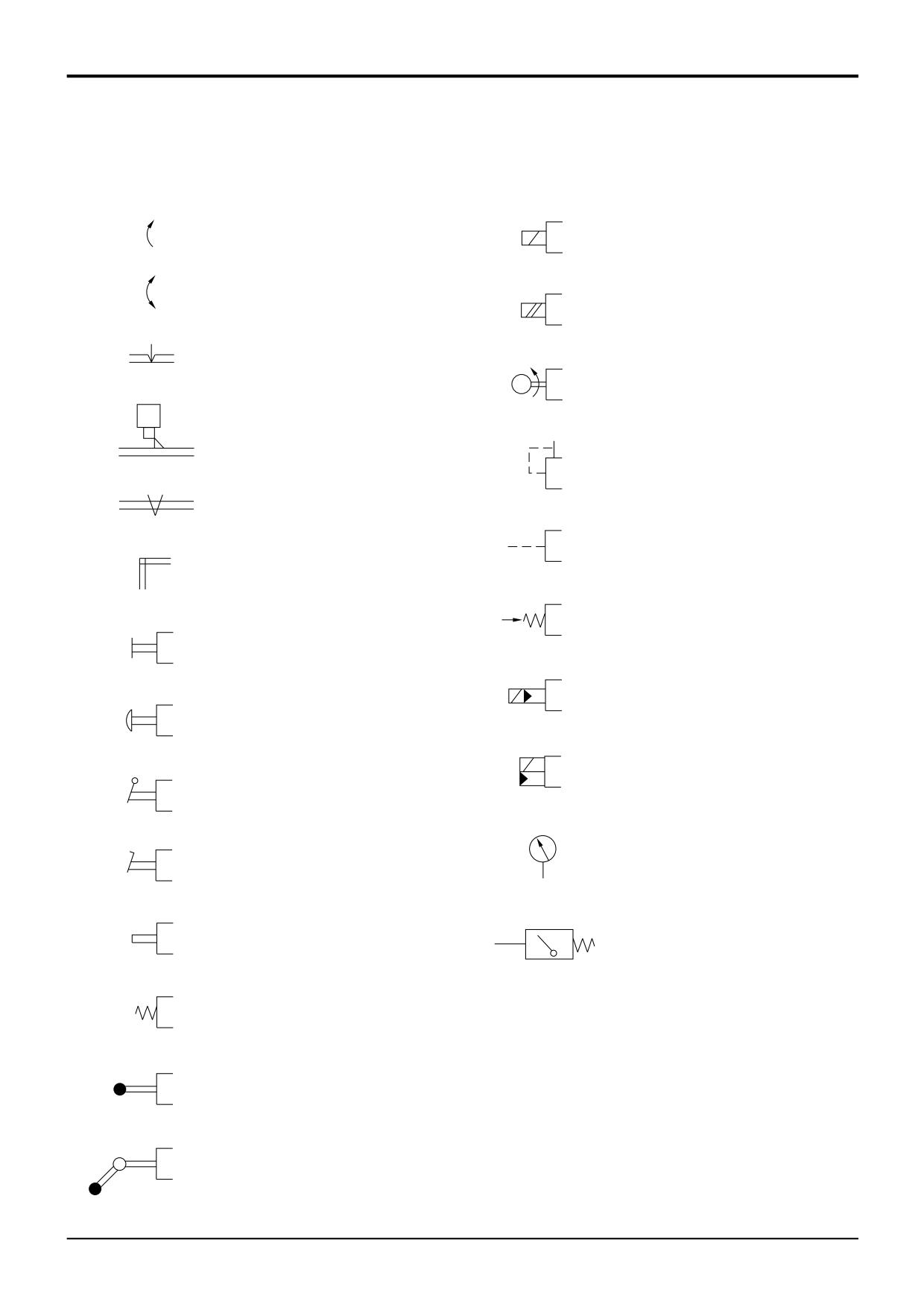
Symbols (cont'd)
Energy Transmissions and Conditioning
Working line, return or feed
Reservoir - return line
above fluid level
Pilot control
Reservoir - return line
below fluid level
Drain lines
Flexible pipe
Header tank
Pressure sealed tank
Line junction
Accumulator
Crossing lines
Filter or strainer
Air bleed
Water trap
Line plugged, also
pressure test point
Cooler - with no
indication of coolant flow
Line plugged with
take off line
Cooler - indicating
direction of coolant flow
Quick release
couplings - connected
Heater
A189710
A189720
Quick release
couplings - disconnected
9803/3280
Issue 1
Section E
Hydraulics
Section E
3 - 13
Basic System Operation
3 - 13
Introduction to Hydraulic Schematic
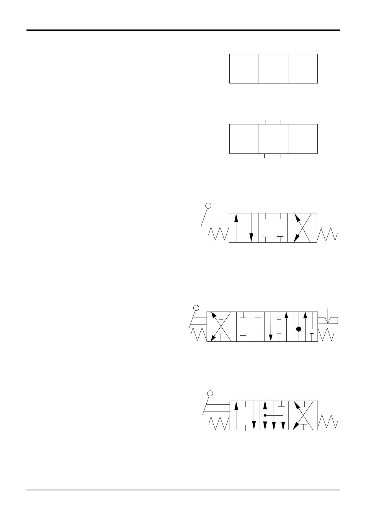
Symbols (cont'd)
Control Mechanisms
Rotating shaft-one direction
Solenoid one winding
Rotating shaft-two directions
Solenoid two winding
Detent
M
Electric motor operated
Locking device
Internal pressure
pilot operated
Over centre device
External pressure
pilot operated
Simple linkage
Pressure operated
spring release
General control
Pilot operated by solenoid
pilot valve
Push button operated
Pilot operated by a solenoid
or separate pilot valve
Lever operated
Pressure gauge
Pedal operated
Stem operated
Pressure switch
Spring operated
Roller operated
Roller trip operated
(one directional)
S189730
S189740
9803/3280
Issue 1
Section E
Hydraulics
Section E
3 - 14
Basic System Operation
3 - 14
Introduction to Hydraulic Schematic
Symbols (cont'd)
Position 1
Position 2
Position 3
Control Valves
Control valves are usually represented by one or more
square boxes.
Fig. 1 shows a control valve represented by three boxes.
FIG 2
The number of boxes indicates the number of possible valve
operating positions, (4 boxes - 4 positions etc).
Fig. 2 - In circuit diagrams the pipework is usually shown
connected to the box which represents the unoperated
condition. (Hydraulic circuit diagrams are usually shown in
the unoperated condition).
Fig. 3 shows a valve described as a 3- position, 4-port
control valve. Port describes the openings to and from the
valve by which the hydraulic fluid enters or leaves. In the fig
shown, Position 2 indicates that in an unoperated condition
Port 1
Port 3
all 4 ports are blocked.
FIG 3
If the valve spool was moved to Position 1, movement of the
spool would connect Port 1 to Port 2, and Port 3 to Port 4.
If the valve spool was moved to Position 3, movement of the
spool would connect Port 1 to Port 4, and Port 3 to Port 2.
It must be noted that not all spools are of the same type.
Their operating designs can be seen by following the path
the flow arrows take in their respective operating squares.
Port 2
Port 4
Three typical JCB style spools are known as 'D' spools, 'F'
spools and 'N' spools.
The 'D' spools generally control rams because when in the
FIG 4
neutral position the outlet ports are blocked, preventing ram
movement. Fig 3 shows a 'D' type spool.
Fig 4 - 'F' spools are often shown as four position spools
with the three normal positions for neutral and service
control; and the forth position, which has a detent, connects
both sides of the ram together to allow the service to 'float'.
Fig 5 - 'N' spools are sometimes used to control hydraulic
motors, and it can be seen from the flow arrows, that in
neutral position both service ports are connected to the
exhaust oil port
FIG 5
A189760
9803/3280
Issue 1
Section E
Hydraulics
Section E
3 - 15
Basic System Operation
3 - 15
Introduction to Hydraulic Schematic
Symbols (cont'd)
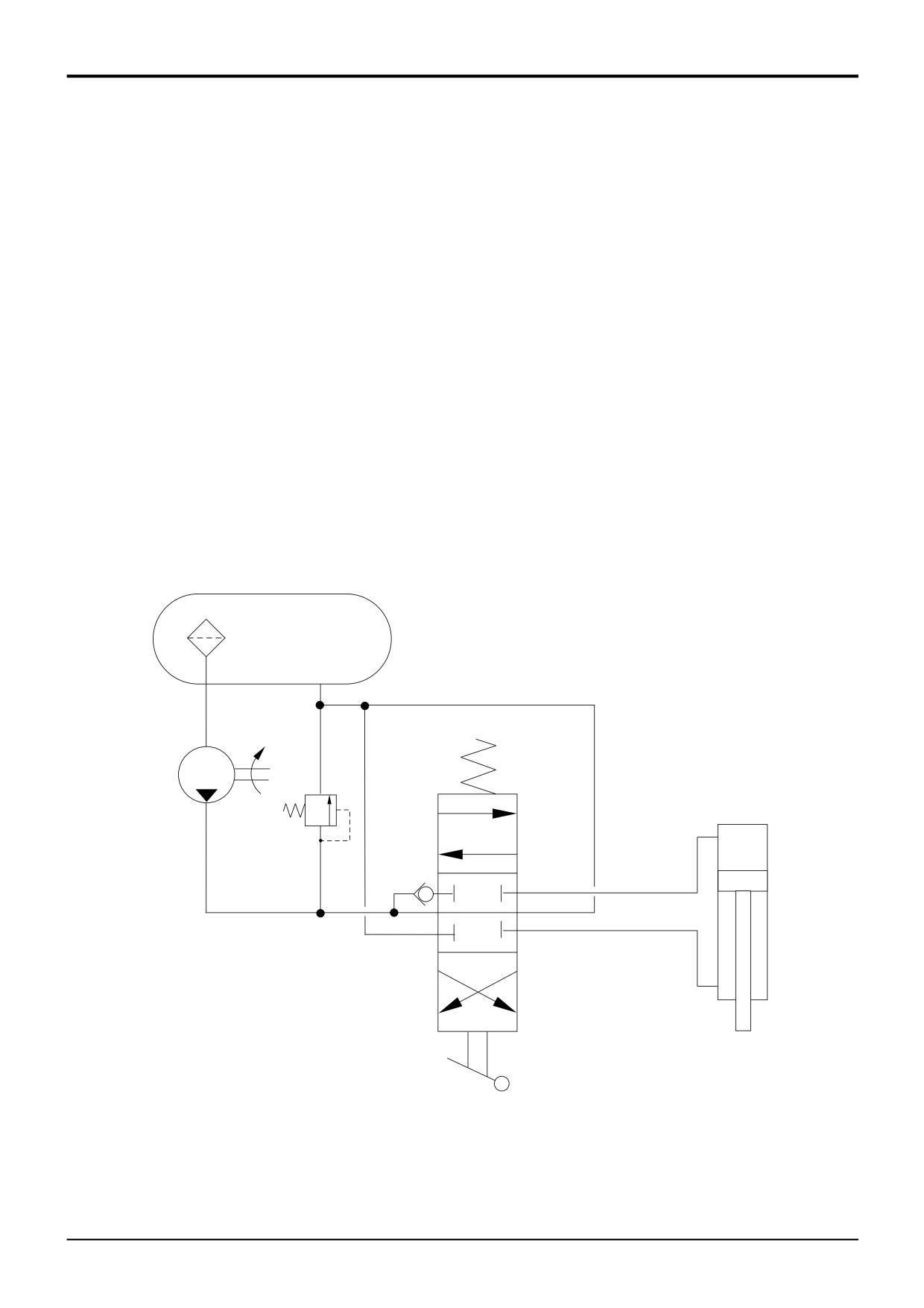
Example of Schematic Circuit
Some of the symbols described on the preceding pages
Example Circuit Key
have been arranged into a simple schematic circuit shown
below.
A
Hydraulic Tank
B
Strainer
Hydraulic tank A is a pressurised tank with an internally
C
Fixed Displacement Pump
mounted strainer B on the suction line to the fixed
D
Relief Valve
displacement pump C. System pressure is limited to the
E
Spool
setting of relief valve D.
F
One Way Valve
G
Double Acting Hydraulic Ram
Valve spool E is an open-centre spool that is in neutral
position; flow from the pump passes through the spool and
returns to the hydraulic tank.
If the lever operated spool is moved away from neutral
position hydraulic fluid is directed to either head side or rod
side of hydraulic ram G. Notice that the fluid must first open
one way valve F before flowing to the ram.
A
B
C
G
D
E
F
A189770
9803/3280
Issue 1
Section E
Section E
Hydraulics
3 - 20
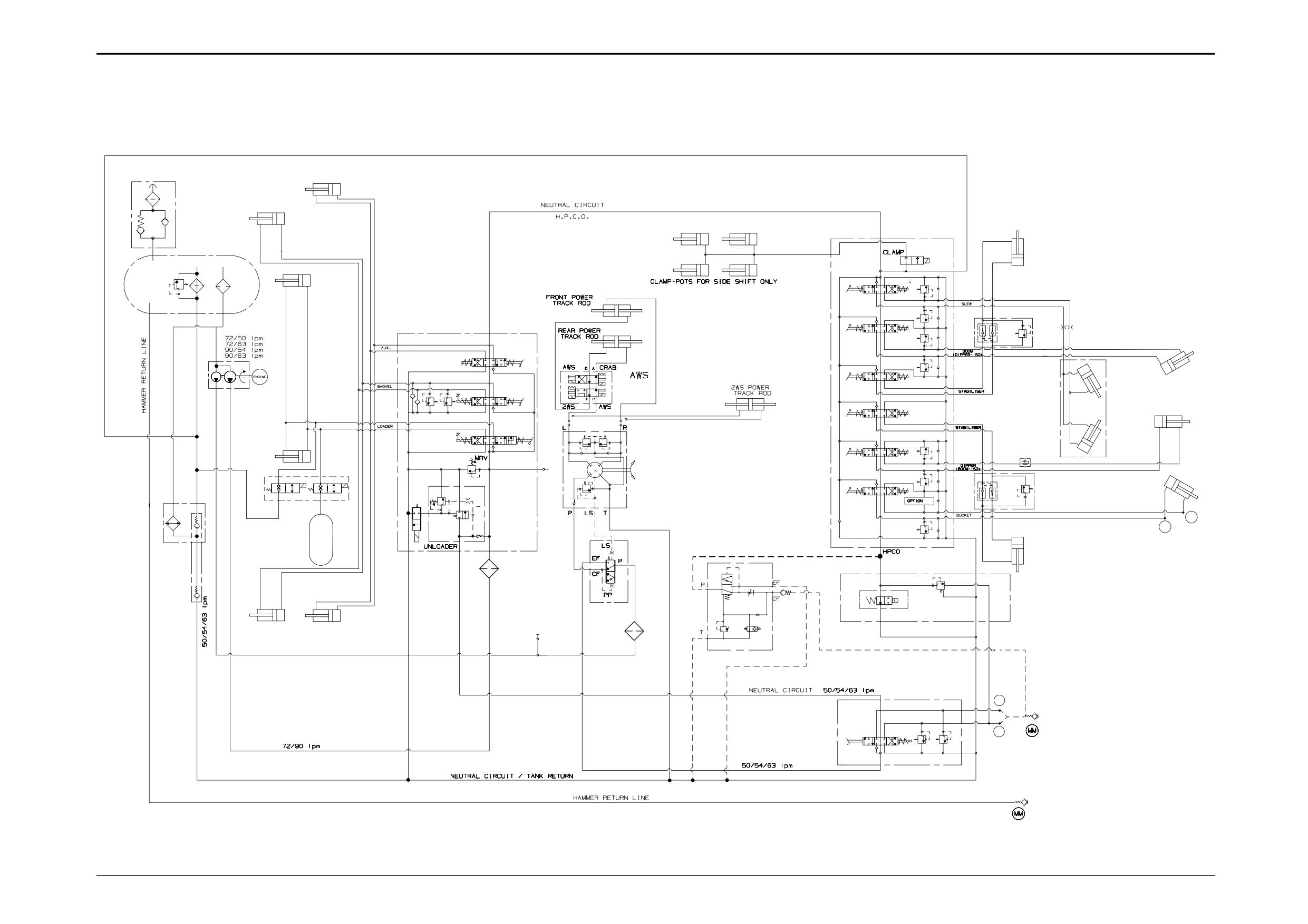
Circuit Schematics - Fixed Flow
3 - 20
14
Check Valve (optional)
3CX, 4CX, 214, 215, 217 & ‘S’ Series Machines
15
Smooth Ride System Selector Valve Assembly
16
Smooth Ride System Accumulator
The policy of JCB is one of continuous improvement,
26
Hydraulic Oil Cooler
therefore as products develop, there may be variations to
31
Shovel Ram R.H.
the circuits.
32
Shovel Ram L.H.
33
Lift Ram R.H.
Component Key
34
Lift Ram L.H.
C
Tank Cap
35
Clam Shovel Ram R.H.
JJ
Connections (as applicable)
36
Clam Shovel Ram L.H.
P1
Pump, Main Section
38
2 Wheel Steer Power Track Rod
P2
Pump, Secondary Section
39
AWS Rear Axle Power Track Rod
P2A
Pressure Test Point (auxiliary & unloader)
40
AWS Front Axle Power Track Rod
S
Suction Line
41
AWS Valve Assembly
T
Tank
42
Steer Control Valve
M
Connections (as applicable)
43
Shock Valves
MM
Quick Release Couplings
44
Steer Control Valve Relief Valve
1A
Neutral Circuit Line
51
Bucket Ram
1B
Neutral Circuit Line
52
Boom Ram
2A
Neutral Circuit Line
53
Stabiliser Ram
3
Loader Valve Block
54
Stabiliser Ram
3A
Pressure Test Point (M.R.V.)
55
Dipper Ram
3B
Unloader Pilot Valve
56
Left Hand Slew Ram
3C
Loader Lift Ram Spool
57
Right Hand Slew Ram
3D
Loader Shovel Ram Spool
59
Stabiliser Check Valve
3E
Clamshovel Spool
62
Hydraclamps (Sideshift Machines Only)
3F
Shovel Ram Head Side A.R.V.
65
Restrictor
3G
Shovel Ram Rod Side A.R.V.
66
Dipper Restrictor with By-Pass
3J
Load Hold Check Valve
67
Manual Isolation Valve
3L
Unloader Valve Spool
68
Manual Change Over Valve
3M
Main Relief Valve
69
Extending Dipper Ram
3N
Unloader Check Valve
70
High Flow Options
3Q
Hydraulic Speed Control Solenoid
71
Low Flow options
4
Excavator Valve Block
Excavator services shown here are to the JCB control
pattern. If ISO, Case or Ford control pattern is used, the
excavator spools and relief valves will apply to different
services.
70
HIGH FLOW OPTIONS
4A
Slew Spool
4B
Boom Spool
4C
Stabiliser Spool
4D
Stabiliser Spool
4E
Dipper Spool
4F
Bucket Spool
4G
Hydraclamp Valve (Sideshift Machines Only)
4H
Slew A.R.V.
4J
Slew A.R.V.
4K
Boom Ram Rod Side A.R.V.
4L
Boom Ram Head Side A.R.V.
4M
Dipper Ram Head Side A.R.V.
4N
Dipper Ram Rod Side A.R.V.
4P
Bucket Ram Head Side A.R.V.
5
Auxiliary Valve Block (foot operated)
71
LOW FLOW OPTIONS
5A
Auxiliary Spool
5B
A.R.V.
5C
A.R.V.
JJ
MM
6
In-tank Filter
6A
Filter By-pass Valve
Hammer
6B
Suction Strainer
69
7
Priority Valve
M
MM
8
Filter
M
9
Filter
67
68
10
Diverter Valve (hammer only)
11
11
Sequence Valve (hammer only)
EXTENDING
MM
DIPPER
12
Flow Regulator Valve
A325660
13
Anti-cavitation Check Valve
9803/3280
Issue 1
Section E
Hydraulics
Section E
3 - 21
Circuit Schematics - Fixed Flow
3 - 21
3CX, 4CX, 214, 215, 217 & ‘S’ Series Machines
C
35
1B
31
4
T
62
54
4G
6
33
4H
6B
4A
6A
40
4J
S
3
65
59
4B
4K
39
3E
4L
56
3F
38
52
41
4C
3D
P2
P1
3G
3J
55
4D
3C
43
34
66
57
3B
3J
3A
4M
42
4E
P1
P2
15
4N
2A
3M
59
51
26
3Q
44
4F
T
ACC
JJ
3L
JJ
4P
T
16
3N
7
53
8
10
13
11
32
14
12
36
P2A
9
1A
M
5A
5B
M
5C
A262643
9803/3280
Issue 1
Section E
Hydraulics
Section E
3 - 22
Circuit Schematics - Fixed Flow
3 - 22
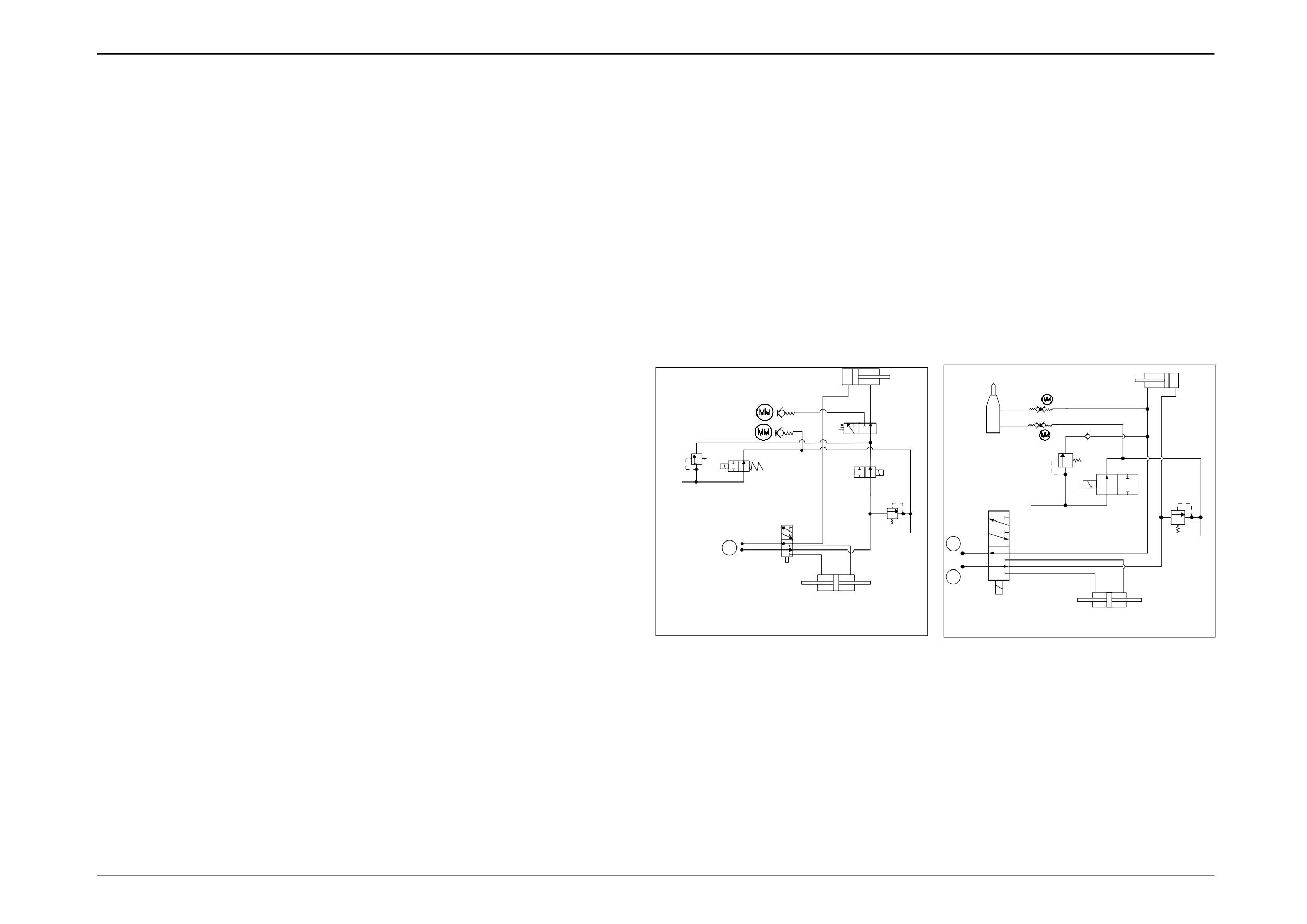
3CX ‘S’ Series & 4CX Gear Pump Options
3CX ‘S’ Series Options
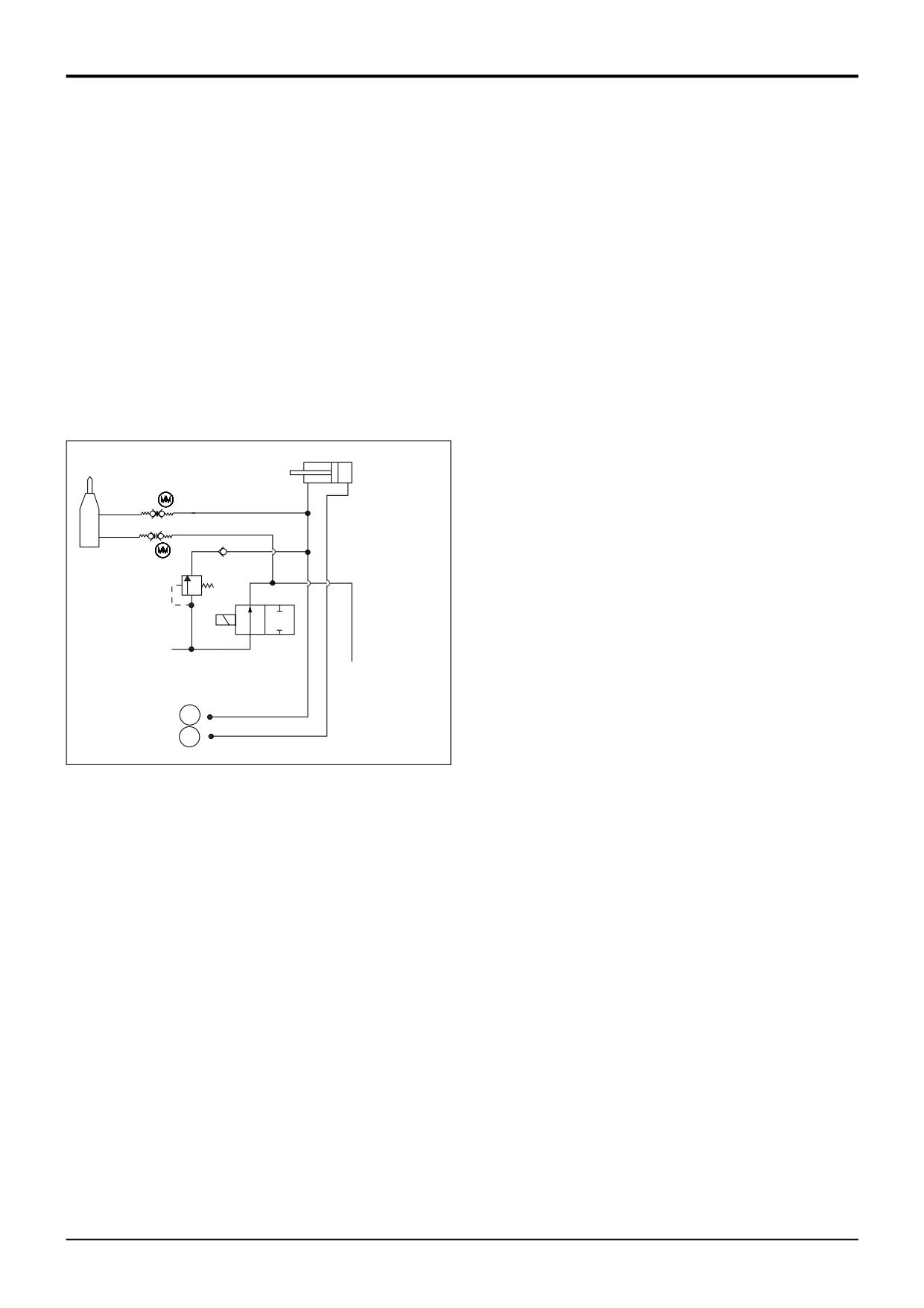
This circuit shows the Extending Dipper and Power
This circuit shows the Low Flow Hammer, Extending Dipper
Sideshift, for the main hydraulic circuit see pages E/3-20
and Power Sideshift, for the main hydraulic circuit see
and E/3-21.
pages E/3-20 and E/3-21.
Component Key
Component Key
HPCO High Pressure Carry Over (From Excavator Valve
HPCO High Pressure Carry Over (From Excavator Valve
Block 4)
Block 4)
M
Hydraulic Connections
M
Hydraulic Connections
MM
Quick Release Couplings
MM
Quick Release Couplings
T
Hydraulic Tank Return
T
Hydraulic Tank Return
10
Diverter valve
11
Sequence valve
11
Sequence valve
69
Extending Dipper Ram
69
Extending Dipper Ram
72
Change Over Valve
72
Change Over Valve
73
Power Sideshift Cylinder
73
Power Sideshift Cylinder
74
Relief Valve
74
Relief Valve
76
Isolation Valve
75
Manual Change Over Valve
77
Hammer
76
Isolation Valve
69
69
75
77
11
11
10
HPCO
76
HPCO
76
72
72
74
T
74
M
T
M
M
73
A325670
73
A327030
9808/3280
Issue 1
Section E
Section E
Hydraulics
3 - 23
Circuit Schematics - Fixed Flow
3 - 23
3CX ‘S’ Series Options
This circuit shows the Low Flow Hammer and Extending
Dipper, for the main hydraulic circuit see pages E/3-20 and
E/3-21.
Component Key
HPCO High Pressure Carry Over (From Excavator Valve
Block 4)
M
Hydraulic Connections
T
Hydraulic Tank Return
11
Sequence valve
69
Extending Dipper Ram
76
Isolation Valve
77
Hammer
69
77
11
76
HPCO
T
M
M
A327040
9803/3280
Issue 1
Section E
Section E
Hydraulics
3 - 24
Circuit Schematics - Fixed Flow
3 - 24
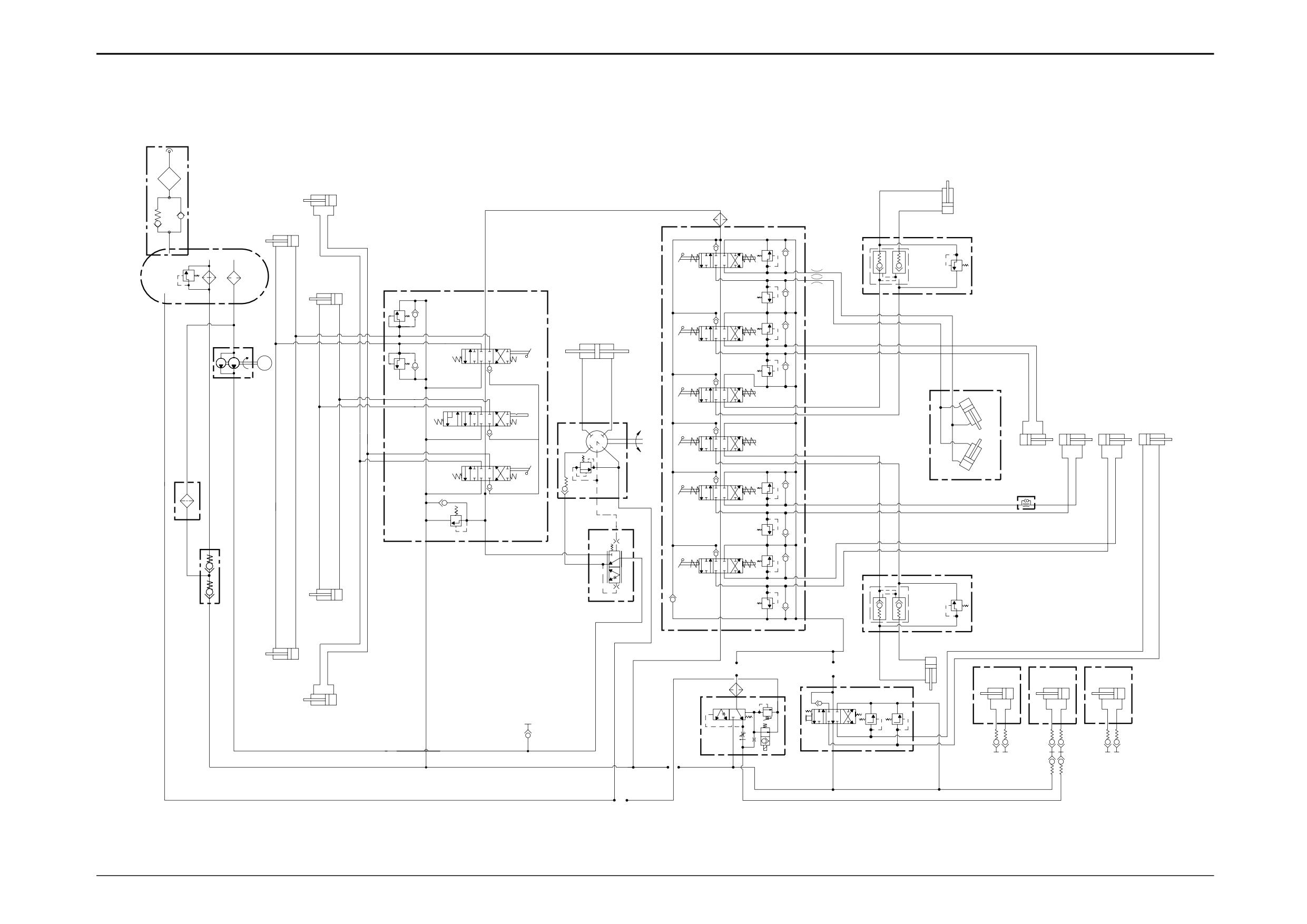
214e Machines
Component Key:
A
Hydraulic Tank
B
Return filter
C
Hydraulic Oil Cooler
D
Hydraulic Pump
E
Twin Check Valve
F
Shovel Rams
G
Quick Release Couplings
H
Lift Rams
J
Loader Valve Block
J1
Main Relief Valve
J2
Auxiliary Spool
J3
Lift Spool
J4
Shovel Spool
K
Flow Regulator Valve (Option)
L
Pressure Test Point
M
Auxiliary Valve Block (Option)
Either option K or M can be fitted but not both.
N
Steer Control Valve
P
Auxiliary Rams
Q
Priority Valve
S
Excavator Valve Block
S1
Slew Spool
S2
Boom Spool
S3
Stabiliser Spool
S4
Stabiliser Spool
S5
Dipper Spool
S6
Bucket Spool
W
Stabiliser Rams
Y
One Way Restrictor
Z
Slew Rams
AA
Boom Ram
BB
Dipper Ram
CC
Bucket Ram
DD
Suction Strainer
EE
Stabiliser Check Valve
FF
Last Chance Filter
GG
Tank Cap
HH
Extending Dipper
1
2WS Front Power Track Rod
Note: For smooth ride system schematic, refer to Circuit
Descriptions - Smooth Ride System.
9803/3280
Issue 2*
Section E
Hydraulics
Section E
3 - 25
Circuit Schematics - Fixed Flow
3 - 25
214e Machines
GG
P
NEUTRAL CIRCUIT H.P.C.O.
FF
S
W
F
A
EE
S1
SLEW
B
DD
H
SHOVEL
1
J4
S2
BOOM
ENGINE
D
LOADER
J3
S3
Z
STABILISER
L
R
BB
CC
HH
N
S4
AA
AUX
J2
STABILISER
Z
C
Y
P
LS
T
S5
DIPPER
MRV
J1
J
LS
EF
P
CF
S6
Q
BUCKET
PP
EE
H
H.P.C.O.
E
W
F
HAMMERMASTER
HAMMERMASTER
HAMMERMASTER
260L
280
360
FF
P
B
L
A
G
G
NEUTRAL CIRCUIT / TANK RETURN
M
K
HAMMER RETURN
HAMMER FEED
A408750
9803/3280
Issue 2*
Section E
Hydraulics
Section E
3 - 26
Circuit Schematics - Variable Flow
3 - 26
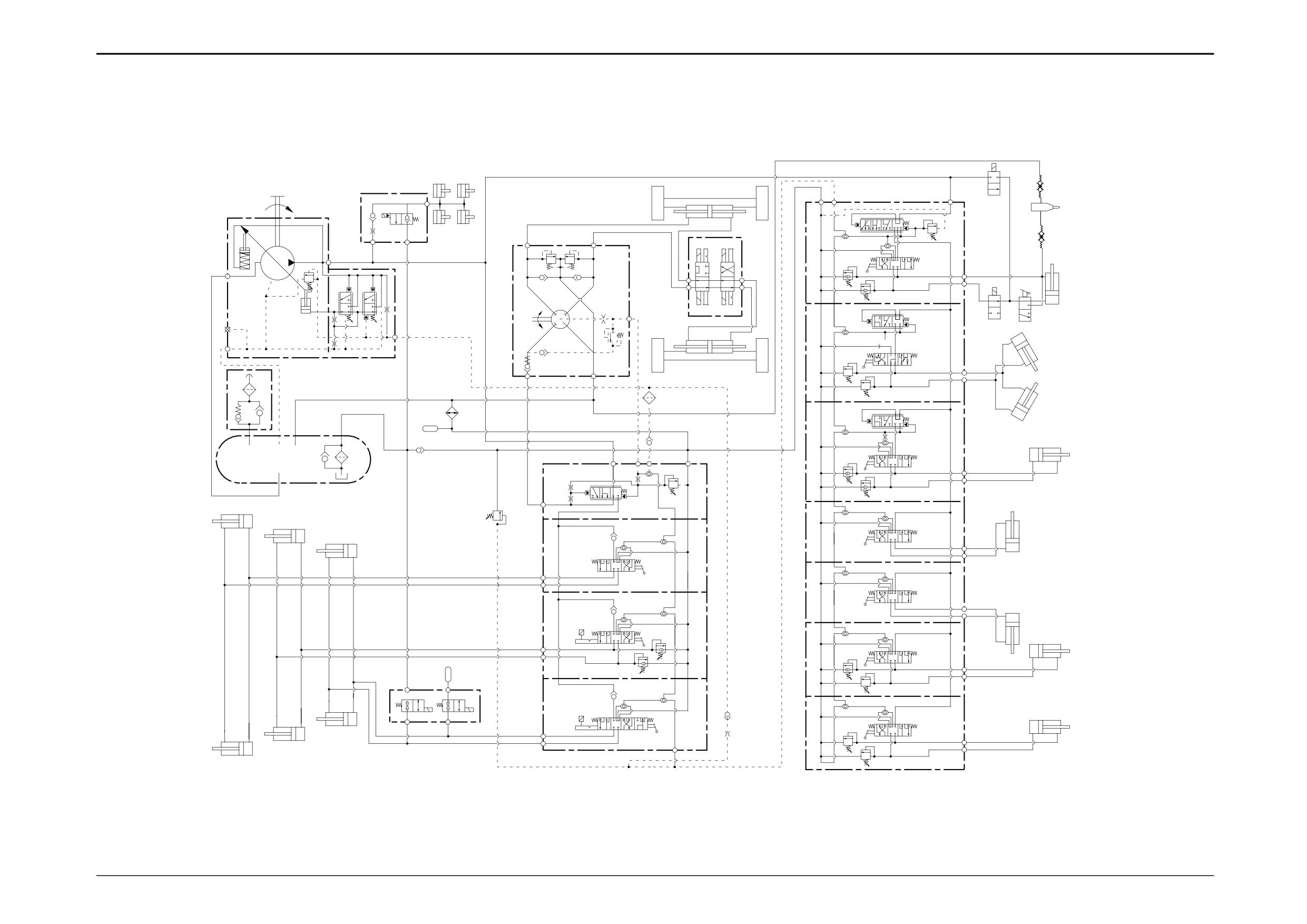
4CXE, 4CX Super Machines
(7 Spool With High Flow Options)
49
T
LS
P
25
7
50
54
P
8
26
49
3
L
R
17
18
P
T
45
B
48
15
S
27
B
T
B
5
6
A
53
P
A
15A
46
4
51
LS
52
L
28
17
18
L1
47
16
29
B
36
P
T
A
16
43
T
28
17
18
37
P
PRLS
LS
T
1
15
9
30
B
11
17
10
A
2
15
PR
20
17
18
21
44
19
17
22
B
31
18
12
38
A
B
17
18
A
32
B
19
17
39
18
A
13
15
17
18
40
B
A
15
33
B
24
15
A
T
ACC
16
23
19
17
18
14
17
18
41
22
P1
P2
B
16
34
B
21
A
LS
A
20
16A
A278942
9803/3280
Issue 1
Section E
Section E
Hydraulics
3 - 27
Circuit Schematics - Variable Flow
3 - 27
4CX, 4CX Super Machines
(7 Spool With High Flow Options)
Component Key
Small letters on the schematic indicate port markings. Refer
to Technical Data pages at the beginning of this section for
more information. Ports A and B are always identified as
service ports (feed and return from respective ram).
38
Stabiliser Ram
T
Hydraulic Tank
39
Stabiliser Ram
1
By-pass Filter
40
Dipper Ram
2
Suction Line
41
Bucket Ram
P
Pump Variable Flow
42
Accumulator
3
Stroking Piston
43
Oil Cooler
4
Control Piston
44
Load Sense Relief Valve
5
System Pressure Spool
45
Steer Unit Assembly
6
Stand-by Pressure Spool
46
Steer Valve
7
Hydraclamp Valve
47
Relief Valve
8
Hydraclamps
48
Shock Valves
9
Loader Valve Block
49
Quick release Couplings
10
Priority Inlet Section
50
Isolation Valve
11
Relief Valve †
51
Extending Dipper Isolation Valve
12
Auxiliary Service Spool
52
Foot Valve
13
Shovel Service Spool
53
Extending Dipper Ram
14
Lift Service Spool
54
Hammer
15
Auxiliary Relief Valves (anti-cavitation)
15A
ARV item 16 if Rockerbreaker Application
† Note: Steer circuit pressure is controlled by a relief valve
16
Auxiliary Relief Valves (direct acting)
housed in the hydraulic steer unit (refer to Section H
16A
ARV Only Fitted For Rockbreaker Application
Steering). The priority relief valve housed in the loader valve
17
Secondary Shuttle Valve
must be set at 2500 lb/in2 (173 bar, 176 kgf/cm2) this will
18
Primary Shuttle Valve
ensure it does not interfere with the operation of the relief
19
Load Hold Check Valve
valve housed in the hydraulic steer unit.
20
Auxiliary Rams
21
Shovel Rams
22
Lift Rams
23
Smooth Ride Selector Valve
24
Smooth Ride Accumulator
25
Backhoe Loader Valve Block
26
Extradig Priority Valve
27
Extradig Service Spool
28
Compensator Valves
29
Slew Service Spool
30
Boom Service Spool
31
Stabiliser Service Spool
32
Stabiliser Service Spool
33
Dipper Service Spool
34
Bucket Service Spool
35
Extradig Ram
36
Slew Rams
37
Boom Ram
9803/3280
Issue 1
Section E
Section E
Hydraulics
3 - 28
Circuit Schematics - Variable Flow
3 - 28
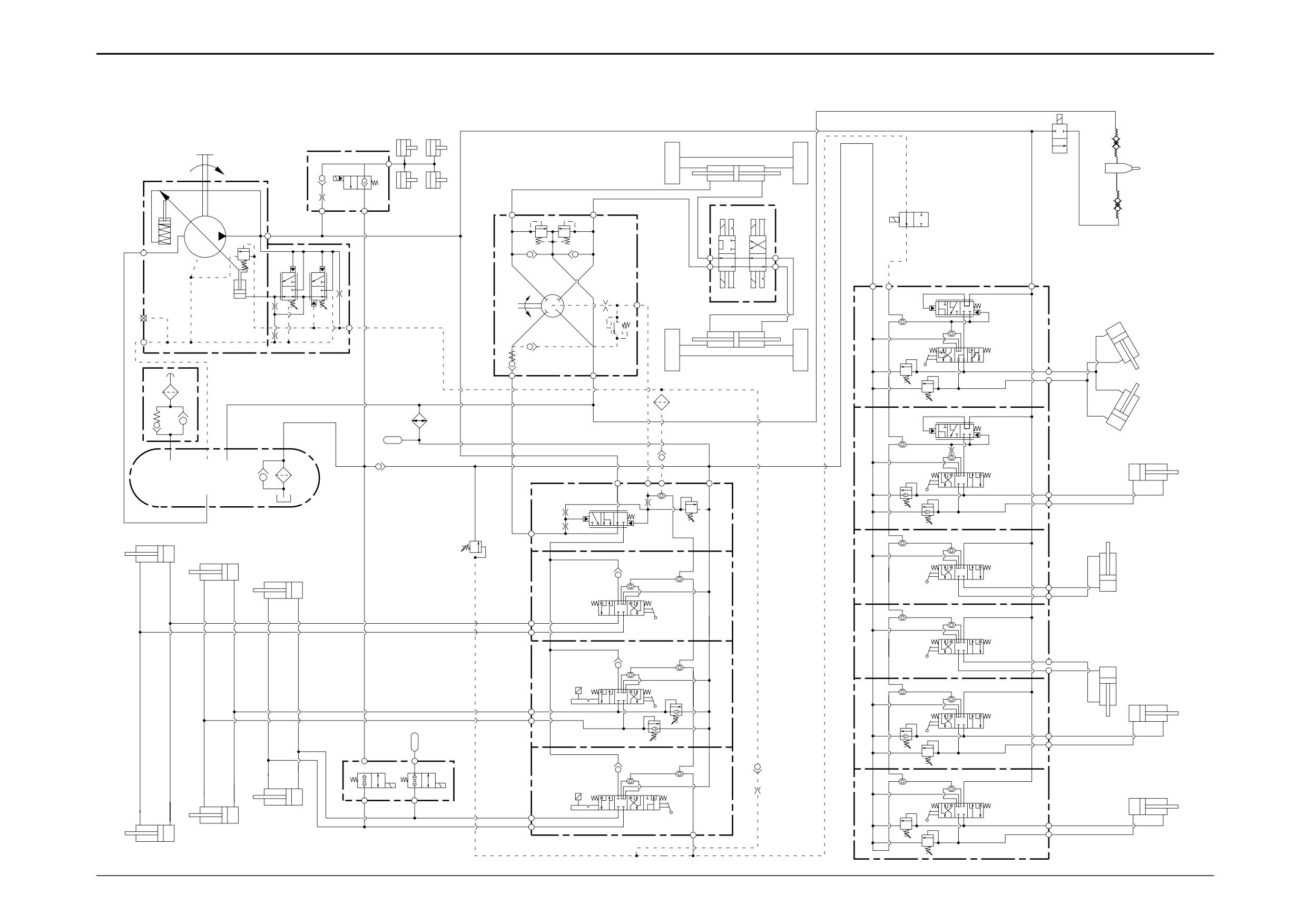
4CX, 4CX Super Machines
(6 Spool With High/Low Flow Options)
Component Key
Small letters on the schematic indicate port markings. Refer
to Technical Data pages at the beginning of this section for
more information. Ports A and B are always identified as
service ports (feed and return from respective ram).
38
Stabiliser Ram
T
Hydraulic Tank
39
Stabiliser Ram
1
By-pass Filter
40
Dipper Ram
2
Suction Line
41
Bucket Ram
P
Pump Variable Flow
42
Accumulator
3
Stroking Piston
43
Oil Cooler
4
Control Piston
44
Load Sense Relief Valve
5
System Pressure Spool
45
Steer Unit Assembly
6
Stand-by Pressure Spool
46
Steer Valve
7
Hydraclamp Valve
47
Relief Valve
8
Hydraclamps
48
Shock Valves
9
Loader Valve Block
49
Quick release Couplings
10
Priority Inlet Section
50
Isolation Valve
11
Relief Valve †
54
Hammer
12
Auxiliary Service Spool
55
Load Sense Isolation Valve
13
Shovel Service Spool
14
Lift Service Spool
† Note: Steer circuit pressure is controlled by a relief valve
15
Auxiliary Relief Valves (anti-cavitation)
housed in the hydraulic steer unit (refer to Section H
16
Auxiliary Relief Valves (direct acting)
Steering). The priority relief valve housed in the loader valve
16A
ARV Only Fitted For Rockbreaker Application
must be set at 2500 lb/in2 (173 bar, 176 kgf/cm2) this will
17
Secondary Shuttle Valve
ensure it does not interfere with the operation of the relief
18
Primary Shuttle Valve
valve housed in the hydraulic steer unit.
19
Load Hold Check Valve
20
Auxiliary Rams
21
Shovel Rams
22
Lift Rams
23
Smooth Ride Selector Valve
24
Smooth Ride Accumulator
25
Backhoe Loader Valve Block
28
Compensator Valves
29
Slew Service Spool
30
Boom Service Spool
31
Stabiliser Service Spool
32
Stabiliser Service Spool
33
Dipper Service Spool
34
Bucket Service Spool
36
Slew Rams
37
Boom Ram
9803/3280
Issue 1
Section E
Section E
Hydraulics
3 - 29
Circuit Schematics - Variable Flow
3 - 29
4CXE, 4CX Super Machines
(6 Spool With High Flow Options)
49
7
50
54
P
8
L
R
49
3
P
T
45
55
B
48
S
T
B
5
6
P
A
T
LS
P
46
25
4
LS
L
28
X
17
18
L1
47
16
29
B
36
P
T
A
16
43
T
28
17
18
37
P
PRLS
LS
T
15
1
9
30
B
11
17
10
A
2
15
PR
20
17
18
21
44
19
17
22
B
31
18
12
38
A
B
17
18
A
32
B
19
17
39
18
A
13
15
17
18
40
B
15
A
33
B
24
15
A
T
ACC
16
23
19
17
18
17
18
14
41
22
P1
P2
B
16
34
B
21
A
LS
A
20
A327070
A347590
16A
9803/3280
Issue 1
Section E
Section E
Hydraulics
3 - 30
Circuit Schematics - Variable Flow
3 - 30
4CX, 4CX Super Machines
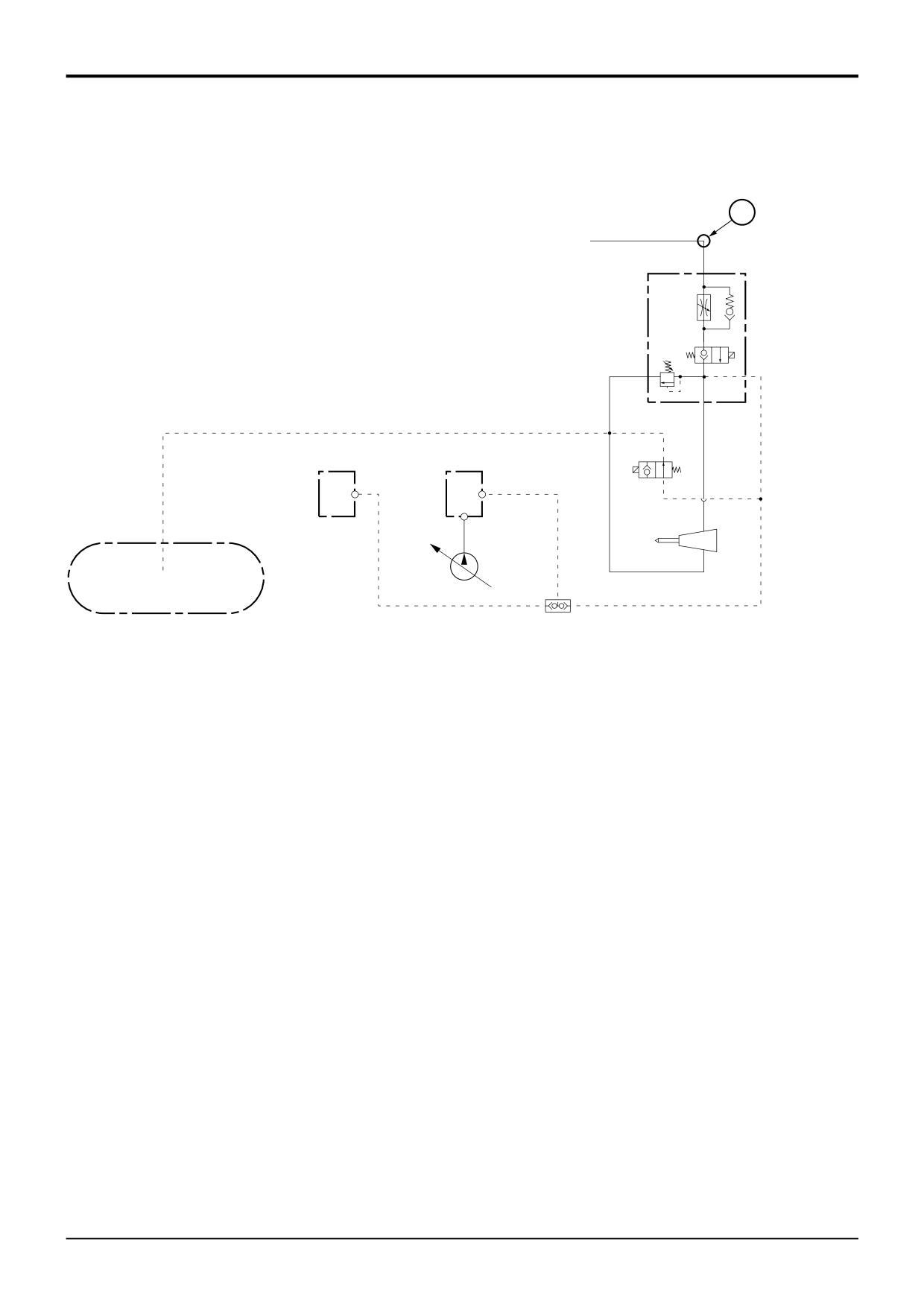
Hand Held Tools Option
X
1
2
3
LS
4
9
25
LS
LS
5
T
P
6
A322650
Component Key
P
Pump Variable Flow
T
Hydraulic Tank
X
Main Circuit Connection
1
Pressure Flow Regulator
2
High Pressure Flow Spool
3
Relief Valve (2000 lb/in2 - 138 bar - 146 kgf/cm2)
4
Load Sense Solenoid
5
Hand Held Tool
6
Shuttle Valve
9
Excavator Valve Block
25
Loader Valve Block
9803/3280
Issue 1
Section E
Hydraulics
Section E
3 - 31
Basic System Operation
3 - 31
Hydraulic Circuit Schematic
Precision Control (Servo)
(Machines up to serial no. 931159)
*
Component Key:
1
Tank
5
Anti Cavitation Check Valve
1A
Breather
6
Hydraulic Oil Cooler
1B
Fill Screen
7
Steer Unit
1C
Suction Strainer
8
Priority Valve
2
Pump, Main Section
9
2WS Power Track Rod Ram
2A
Pump, Secondary Section
10
Extending Dipper Ram
3
Loader Valve Block
11
Lift Ram L.H.
3A
Extending Dipper Spool
12
Lift Ram R.H.
3B
Loader Lift Ram Spool
13
Shovel Ram L.H.
3C
Loader Shovel Ram Spool
14
Shovel Ram R.H.
3D
Clamshovel Spool
15
Clam Shovel Ram L.H.
3E
Extending Dipper Ram Rod Side A.R.V.
16
Clam Shovel Ram R.H.
3F
Extending Dipper Ram Head Side A.R.V.
17
Bucket Ram
3G
Shovel Ram Head Side A.R.V.
18
Dipper Ram
3H
Shovel Ram Rod Side A.R.V.
19
Stabiliser Ram
3L
Unloader Valve Spool
20
Stabiliser Ram
3M
Main Relief Valve (MRV)
21
Boom Ram
3N
Unloader Check Valve
22
Slew Ram L.H.
3P
Unloader Pilot Valve
23
Slew Ram R.H.
3Q
Hydraulic Speed Control Solenoid
24
Hydraclamps (Sideshift Only)
4
Excavator Valve Block
4A
Slew Spool
4B
Boom Spool
4C
Right Stabiliser Spool
4D
Left Stabiliser Spool
4E
Dipper Spool
4F
Bucket Spool
4G
Auxiliary Spool
4H
Hydraclamp Valve (Sideshift Only)
4J
Slew A.R.V.
4K
Slew A.R.V.
4L
Dipper Ram Head Side A.R.V.
4M
DipperRam Rod Side A.R.V.
4N
Boom Ram Rod Side A.R.V.
4P
Boom Ram Head Side A.R.V.
4Q
Bucket Rod Side ARV (Hammer Only)
4R
Bucket Ram Head Side A.R.V.
4S
Bypass Compensator Valve
4T
Load Sense Drain Regulator and Relief Valve
4U
Pilot Operated Check Valve (Hydraclamp)
9803/3280
Issue 2*