JCB 3CX, 4CX, 214e, 214, 215, 217 & VARIANTS Backhoe Loader. Service Manual - page 10
Section D
Controls
Section D
41 - 2
Precision Control (Servo)
41 - 2
Electrical Switches
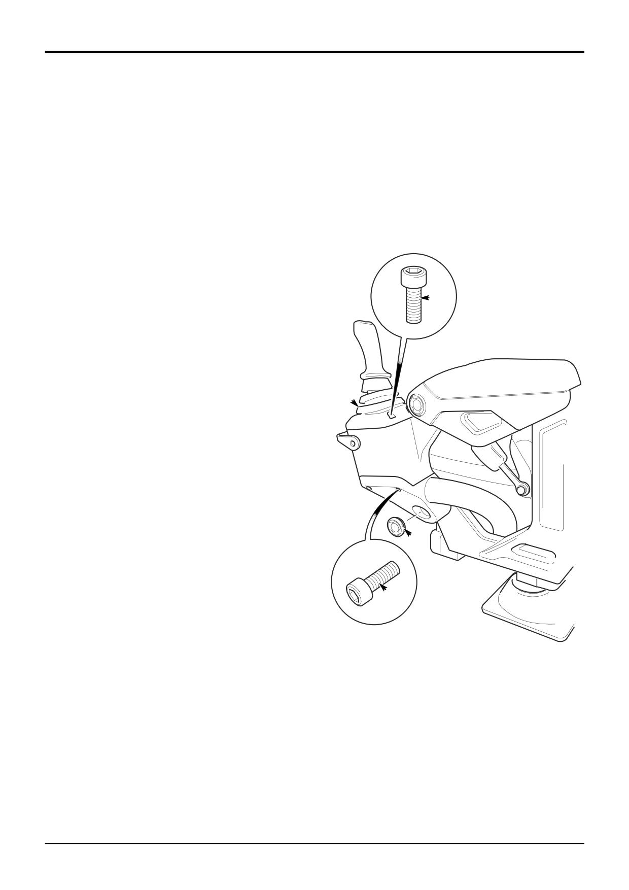
Joystick Mounted Microswitches, Removal and
Seat Mounted Microswitch, Removal, Replacement and
Replacement
Adjustment.
Note that the procedure shows the right hand joystick. the
Important Note: Some machines may be fitted with two
procedure is very similar for the left hand joystick. Note that
seat mounted microswitches, one on each side of the seat.
where the joysticks incorporate more than one switch, all
On Precision Control machines only switch Z is used. Note
switches must be renewed as a complete harness and
that switch Z is located on the left side of the seat when set
switch assembly.
in the rear facing position. When renewing the switch make
sure you re-connect the wiring harness to the correct switch.
Removal
Under no circumstances attempt to connect to the switch on
the right hand side of the seat.
1
With the operator seat set in the rear facing position (for
backhoe operation), pull off the gaiter A.
Removal
2
Reach inside the arm assembly and undo the two arm
rest fixing bolts B. Carefully lift the rear of the arm rest
1
With the operator seat set in the forward facing position
C and pull it to the rear to release.
(for loader operation), uncouple the electrical connector
X. Undo the two retaining screws W and remove the
3
Uncouple the joystick harness connector D from the
switch.
servo harness. Note the orientation of the joystick.
Slacken the lock nut E followed by lock nut F. Unscrew
Replacement
the joystick and remove it from the machine. Remove
lock nuts E and F.
Replacement is the reverse of removal.
4
Drill a small hole in the centre of plastic cap G. Screw in
a self tapping screw. Using pliers, grip the screw and
Adjustment
draw out the cap G. Undo screw H. Lever off the
aluminium base plate J.
The switch must be adjusted to operate only when the
operator seat is locked in the rear facing position. This is
5
Carefully part the two halves of the joystick making sure
essential for safe operation of the machine, preventing
that components are not lost. Lift the switches K off
backhoe operation until the operator is correctly seated.
their location pins. Note that replacement switches are
supplied together with a new base plate J, wiring
1
With the operator seat set in the rear facing position (for
harness and connector already assembled.
backhoe operation), locate the adjustable bolt V on the
seat pedestal. Loosen the lock nut U and screw the bolt
in or out until the switch is heard to operate. Tighten
Replacement
lock nut U.
Replacement is the reverse of removal but note the
2
Start the machine and test the system.
following:
1
When assembling the joystick ensure that the wiring
harness is located correctly. Cable tie L must be
located to prevent strain on the wire connections at the
switches. Make sure that bush M is fitted correctly (if
applicable). If spigot N has been removed make sure it
is fitted with its alignment pin P correctly located. Fit a
new plastic cap G.
2
When screwing the joystick assembly to the control
linkage be sure to orientate it correctly before
tightening the lock nut F.
9803/3280
Issue 1
Section D
Controls
Section D
45 - 1
Precision Control (Servo)
45 - 1
Basic System Operation
Component Location
TBA
9803/3280
Issue 1
Section D
Controls
Section D
45 - 2
Precision Control (Servo)
45 - 2
Basic System Operation
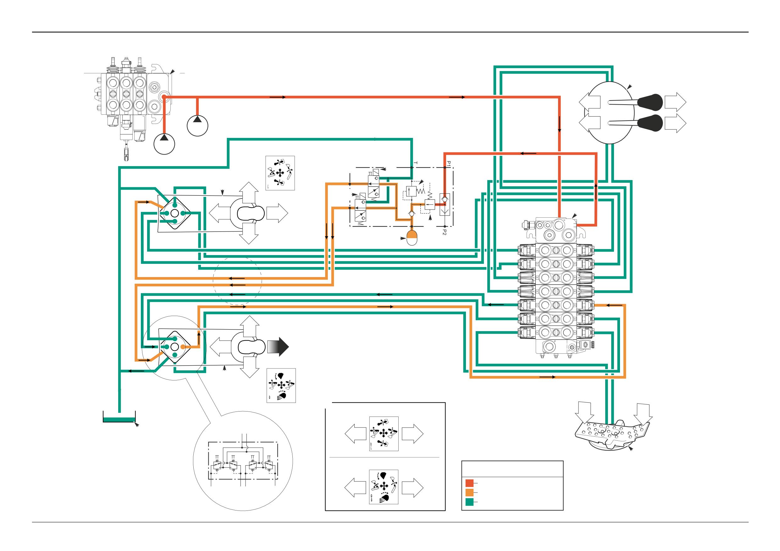
The following section describes the JCB Precision Control
system fitted to machines from January 2003. There is
another JCB Precision Control system fitted to earlier
Component Identification
machines, which is described in a separate section. Refer to
Precision Control (Servo) - Machines up to serial number
A
Right hand joystick controller
931159.
B
Left hand joystick controller
C
Operator seat
Circuit Description
D
Servo pressure supply valve
E
Isolation valve solenoid
The JCB Precision Control system facilitates operation of the
F
Accumulator
backhoe (excavator) via joystick controllers A and B
G
Servo pressure regulating valve
mounted in the arms of the operator’s seat. Unlike manual
H
Servo pressure relief valve
machines the excavator valve spools are moved by hydraulic
J
Loader valve block
pressure and not directly by mechanical levers.
K
Excavator valve block
L
Hydraulic tank
A servo pressure supply valve D maintains a constant supply
of oil at servo pressure to the right and left hand joystick
controllers.
The joysticks each directly operate pressure reducing valves.
These valves in turn operate the excavator valve spools via
hydraulic servo pressure. The interconnecting hoses are
routed to and from the joystick controllers through the
central seat support pillar and then through the cab floor.
The joysticks control the boom, dipper, bucket and slew
functions.
9803/3280
Issue 1
Section D
Controls
Section D
45 - 3
Precision Control (Servo)
45 - 3
Basic System Operation
Hydraulic Operation
Oil at system pressure flows to the servo pressure supply
Component Key:
valve C via a hose connected at the excavator valve J. An
A
Left hand joystick controller
integral pressure regulating valve F maintains the oil at
B
Right hand joystick controller
‘servo’ pressure.
C
Servo pressure supply valve
D
Isolation valve solenoids
When the operator actuates the system by locking the seat
E
Accumulator
in the forward or reverse facing position and raising forward
F
Servo pressure regulating valve
the arm rests, the isolation valve solenoids D are energised
G
Servo pressure relief valve
and oil is directed to the joystick controllers A and B.
H
Loader valve block
J
Excavator valve block
Each joystick controller contains four spool valve ‘capsules’,
K
Hydraulic tank
numbered 1 to 4 on each valve. The valves are operated by
L
Stabiliser controls
moving the associated joystick. With the joystick in the
M
Auxiliary footpedal
neutral position the valves vent the oil from the excavator
S1a
Servo pilot port - Slew ram spool
valve servo pilot ports to tank K.
S1b
Servo pilot port - Slew ram spool
S2a
Servo pilot port - Dipper ram spool
Example Operation:
S2b
Servo pilot port - Dipper ram spool
When the operator moves the right hand joystick B forward
S3a
Servo pilot port - R.H. stabiliser ram spool
this pushes spool 3 down. Oil at servo pressure is directed to
S3b
Servo pilot port - R.H. stabiliser ram spool
port S5b at the excavator valve J. This causes the boom
S4a
Servo pilot port - L.H. stabiliser ram spool
spool to move and operate the boom ram. As the boom
S4b
Servo pilot port - L.H. stabiliser ram spool
spool moves, oil is vented from port S5a via spool 1 and port
S5a
Servo pilot port - Boom ram spool
T to tank.
S5b
Servo pilot port - Boom ram spool
S6a
Servo pilot port - Bucket ram spool
The valve ‘capsules’ feature proportional control. This
S6b
Servo pilot port - Bucket ram spool
enables backhoe precision control. Each valve capsule
S7a
Servo pilot port - Auxiliary spool (Extending Dipper)
regulates the oil pressure supplied to the associated
S7b
Servo pilot port - Auxiliary spool (Extending Dipper)
excavator valve pilot line in proportion to the joystick
position. The further the joystick is moved the greater the
servo pressure and the further the associated excavator
valve spool moves.
Accumulator E maintains servo pressure for several
operations of the excavator spools with the engine stopped.
This allows venting of pressure from the backhoe hydraulic
rams, or lowering of a load in the event of engine failure.
Note: The diagram opposite shows the servo pilot hoses
connected to give the ISO + control pattern. For SAE +
control pattern the servo pilot hoses are connected
differently at the excavator valve as shown at Z.
9803/3280
Issue 1
Section D
Controls
Section D
45 - 4
Precision Control (Servo)
45 - 4
H
A
A
A
1
2
L
LS
P
1H
B
B
B
T
1H
P1
P2
2
1
ISO+
C
D
L.H.
G
A
T
2
2
D
P
1
1
3
J
3
4
F
4
E
S1a
S1b
S2a
S2b
S3a
S3b
S4a
S4b
S5a
S5b
S6a
S6b
2
S7a
S7b
2
1
3
1
3
P
4
4
T
B
R.H.
Z
ISO+
SAE+
2
1
L.H.
K
S2a
1
3
S2b
P
T
M
SAE+
R.H.
Key to Oil Flow & Pressure
1
2
3
4
Full Pressure
S5a
1
3
S5b
Servo
Exhaust
A404990
9803/3280
Issue 1
Section D
Controls
Section D
45 - 5
Precision Control (Servo)
45 - 5
B
A
007
60A
628C
3A
3A
3A
E
N
Q
R
139
3
5
1875
3
3
2
3
2
3
2
628D
1
1
1
1
G
1876
114C
114E
5
1
2
P
F
138
8
10
1874
2
3
2
629A
629D
1
6
H
114G
1877
628
4
1
2
137
SA
J
12
1
1857
412C
UNLOADER (HSC) SWITCH
8
7
ALTERNATOR FREQUENCY
PUMP DUMP
519
1
11
L
CONTROLLER
520
2
SIDE CONSOLE LED
4
5
10
6
2
9
8870
2
1
3
M
K
C
S
921A
1
921A
921B
628A
T
921C
628B
U
929
6
929
V
931
7
931
D
W
875
8
875
114K
SOME MACHINE VARIANTS ONLY
CAB
MAINFRAME
SEAT
A405100
9803/3280
Issue 1
Section D
Controls
Section D
45 - 6
Precision Control (Servo)
45 - 6
Basic System Operation
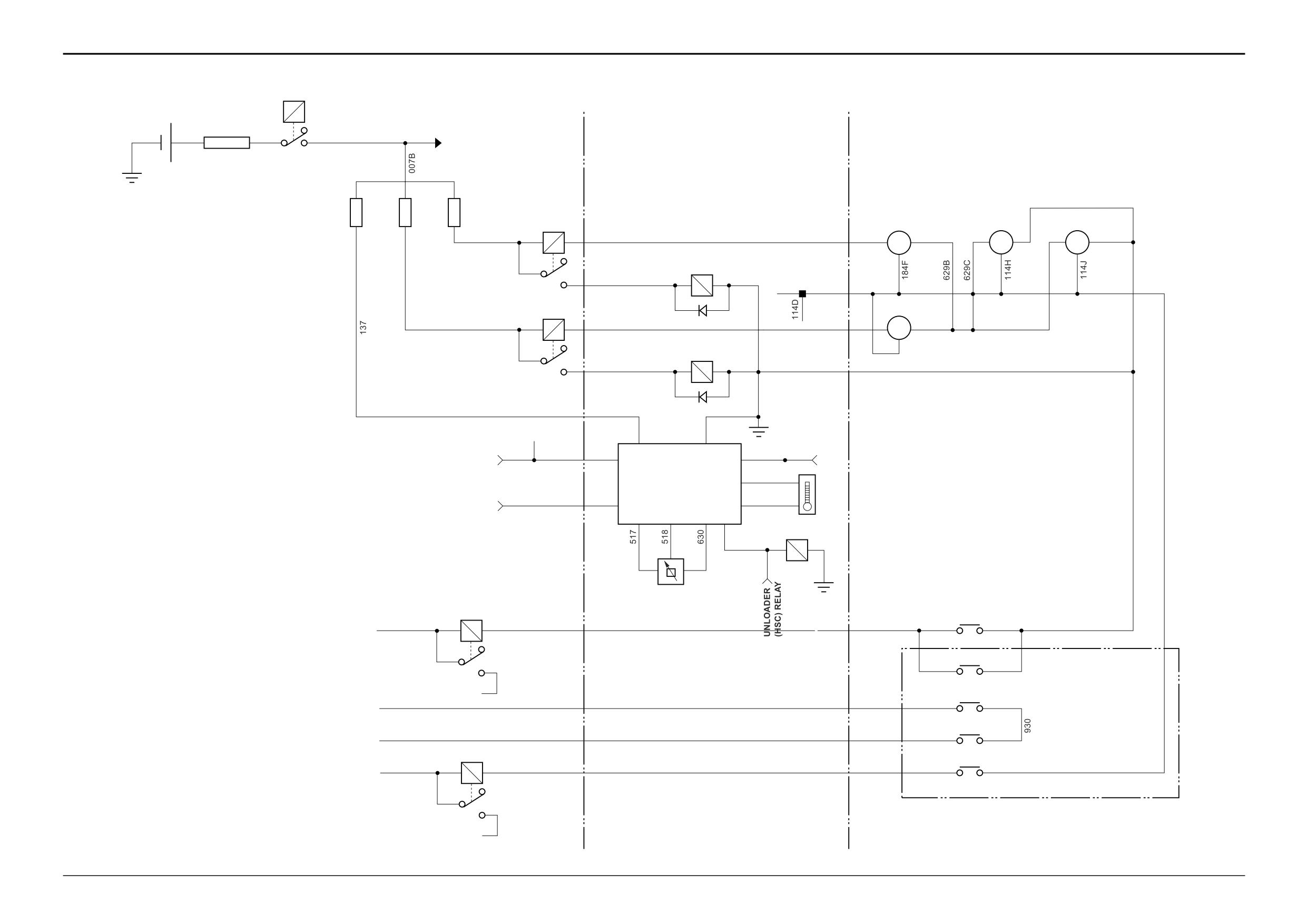
Electrical Operation - Joystick Controller
Pump Dump Controller (Power Management ECU)
There are two solenoid actuated isolation valves
The electronic control unit is mounted in the engine
incorporated in the servo pressure supply valve block, which
compartment and is used to control engine hydraulic power.
when energised direct servo pressure to enable the R.H. and
L.H. joystick controllers. Each valve solenoid is controlled by
When operating under conditions of high engine load and/or
proximity switches via a relay.
conditions of high hydraulic oil temperature (when operating
hammer attachments for example), the pump dump
To make the joystick contollers active the seat must first be
controller J automatically activates the unloading valve (HSC)
locked in the forward or rear facing position, thereby closing
circuit, dumping the hydraulic oil flow from the secondary
either the seat forward proximity switch Q or seat rear
pump section (P2) to tank.
proximity switch R. The operator must then raise forward the
arm rests. Raising the R.H. arm rest closes the R.H. arm
1
Engine Load Condition:
proximity switch P energising relay F and the R.H. isolation
The pump dump controller J compares the ‘actual’ engine
valve solenoid H, making the R.H. joystick controller active.
speed signal from the alternator stator with the engine speed
Similarly the L.H. joystick controller is made active when the
‘demanded’ signal from the throttle position sensor K.
L.H. arm rest is raised forward.
If the engine speed should start to slow under conditions of
When an arm rest is pushed back by the operator, the
high load, the pump dump controller J energises the
proximity switch in that arm rest will open and de-energise
unloader valve (HSC) solenoid M and illuminates an LED on
the relay and solenoid, servo pressure will be isolated and
the side console. The flow from the secondary pump section
the joystick controller in that arm rest will be disabled.
(P2) is dumped to tank reducing the flow available to the
hydraulic system, thereby reducing the load on the engine.
Should the operator move the seat from the forward or rear
When the engine speed recovers the pump dump controller
facing position, the appropriate proximity switch will open
de-energises the unloader valve (HSC) solenoid
and servo pressure to both joystick controllers will be
(extinguishing the LED on the side console), enabling the
isolated, both joystick controllers will be disabled.
hydraulic system to operate normally.
The L.H. joystick houses a horn switch S. On some machine
The operating parameters are as follows:
variants the joysticks also incorporate switches U and V for
control of a hydraulic quickhitch, and an auxiliary
a At engine speeds below 1000 rpm, as determined by
changeover switch W, typically to select between jaw bucket
the throttle position sensor, the unloader valve (HSC)
and extending dipper operation.
solenoid will always be energised.
b At 1000 rpm the unloader valve (HSC) solenoid will be
energised if the engine rpm falls more than 150 rpm
below the ‘no load’ engine speed as determined by the
Component Key:
throttle position sensor. The unloader valve (HSC)
solenoid will de-energise when the engine rpm recovers
A
Primary Fuse
to less than 25 rpm below the ‘no load’ engine speed as
B
Relay
determined by the throttle position sensor.
C
Rear Horn Relay
c At engine speeds greater than 1000 rpm, the unloader
D
Auxiliary Changeover Relay
valve (HSC) solenoid energise and de-energise set
E
Isolation Valve Relay - L.H. Joystick
points are increased by 10 rpm for every 100 rpm
F
Isolation Valve Relay - R.H. Joystick
increase in engine speed.
G
Isolation Valve Solenoid - L.H. Joystick
H
Isolation Valve Solenoid - R.H. Joystick
2
Hydraulic Oil Temperature Condition:
J
Pump Dump Controller (Power Management ECU)
The pump dump controller J monitors the hydraulic oil
K
Throttle Position Sensor
temperature via a sensor L fitted at the rear of the hydraulic
L
Hydraulic Oil Temperature Sensor
oil tank.
M
Unloader Valve (HSC) Solenoid
N
Proximity Switch - L.H. Arm Rest
If the oil temperature should reach 90°C, the pump dump
P
Proximity Switch - R.H. Arm Rest
controller J energises the unloader valve (HSC) solenoid M
Q
Proximity Switch - Seat Forward
and illuminates an LED on the side console. The flow from
R
Proximity Switch - Seat Rear
the secondary pump section (P2) is dumped to tank reducing
S
Rear Horn Switch
the flow available to the hydraulic system. The pump
T
Rear Horn Switch
continues to circulate the oil around the neutral circuit and
U
Quickhitch Switch
through the oil cooler until the oil temperature has reduced
V
Quickhitch Switch
sufficiently. When the oil temperature has fallen to less than
W
Auxiliary Change-over Switch
70°C, the pump dump controller de-energises the unloader
SA
Splice
valve (HSC) solenoid (extinguishing the LED on the side
console), enabling the hydraulic system to operate normally.
9803/3280
Issue 1
Section D
Controls
Section D
45 - 7
Precision Control (Servo)
45 - 7
Basic System Operation
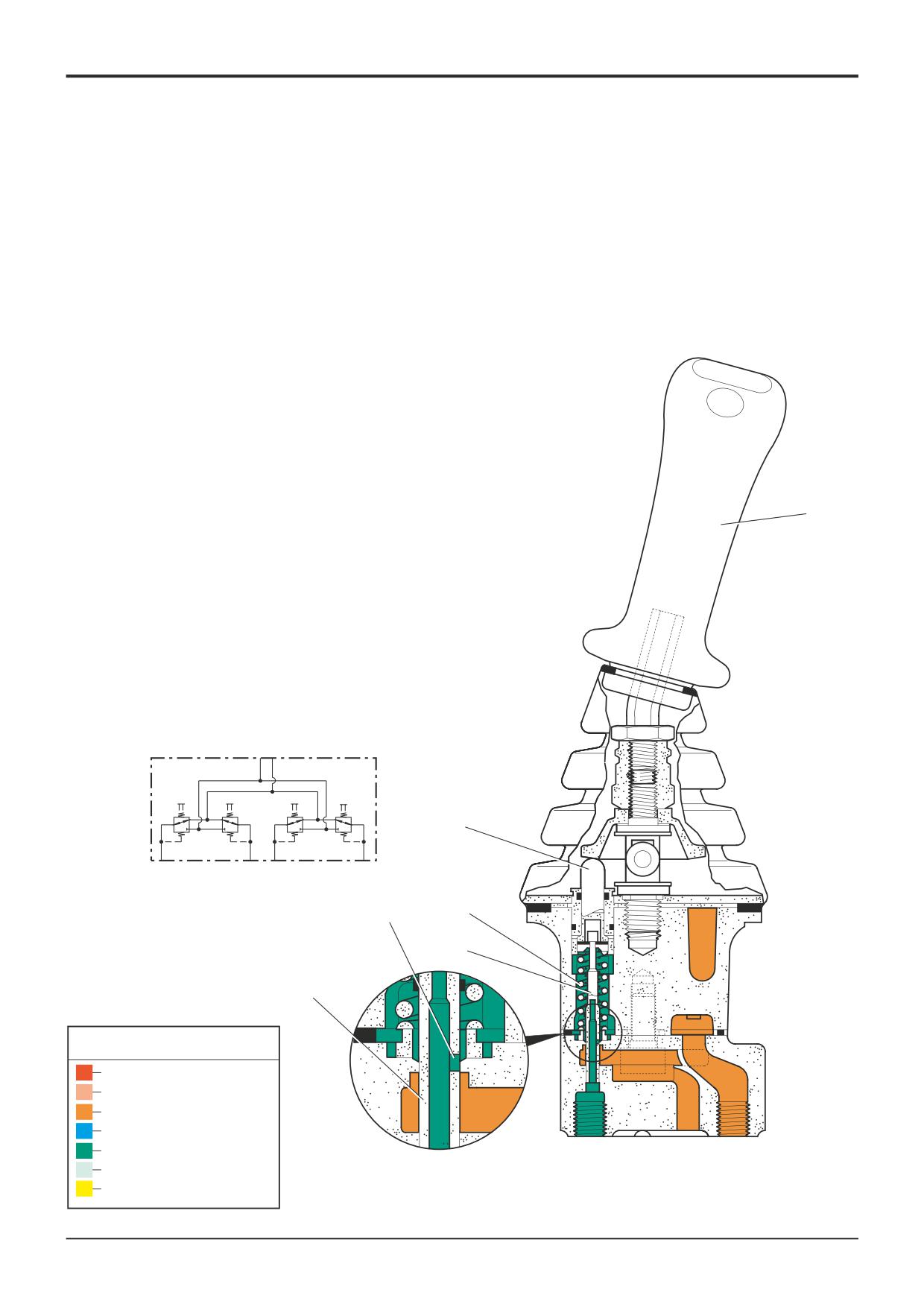
Joystick Controllers - Description
The joystick controllers operate as direct operated pressure
reducing valves and consist of a hand control lever, four
pressure reducing valves and the housing. Each pressure
reducing valve consists of a control spool, control spring,
return spring and a plunger.
In neutral the control lever 5 is kept in the central position by
the return spring 8. Service ports 1, 2, 3 and 4 are connected
to the tank port T via gallery 11.
When the control lever 5 is operated, plunger 9 pushes
against return spring 8 and control spring 7. The control
spring 7 moves the control spool 6 down-wards and closes
the connection between the relevant service port and the
tank port T. The service port is connected to the pressure
port P via gallery 11.
The control phase begins when the control spool 6 has
5
found its balance between the force of the control spring 7
and the force which results from the hydraulic pressure in the
selected port.
The interaction of the control spool 6 and control spring 7
enables the plunger 9 to produce pressure proportional to
the position of the control lever 5.
Hydraulic symbol
P T
9
1
2
3
4
8
11
7
6
Key to Oil Flow & Pressure
Full Pressure
Pressure
Servo
Neutral
Exhaust
P
T
Cavitation
A403930
Lock Up
A390630
9803/3280
Issue 1
Section D
Controls
Section D
45 - 8
Precision Control (Servo)
45 - 8
Basic System Operation
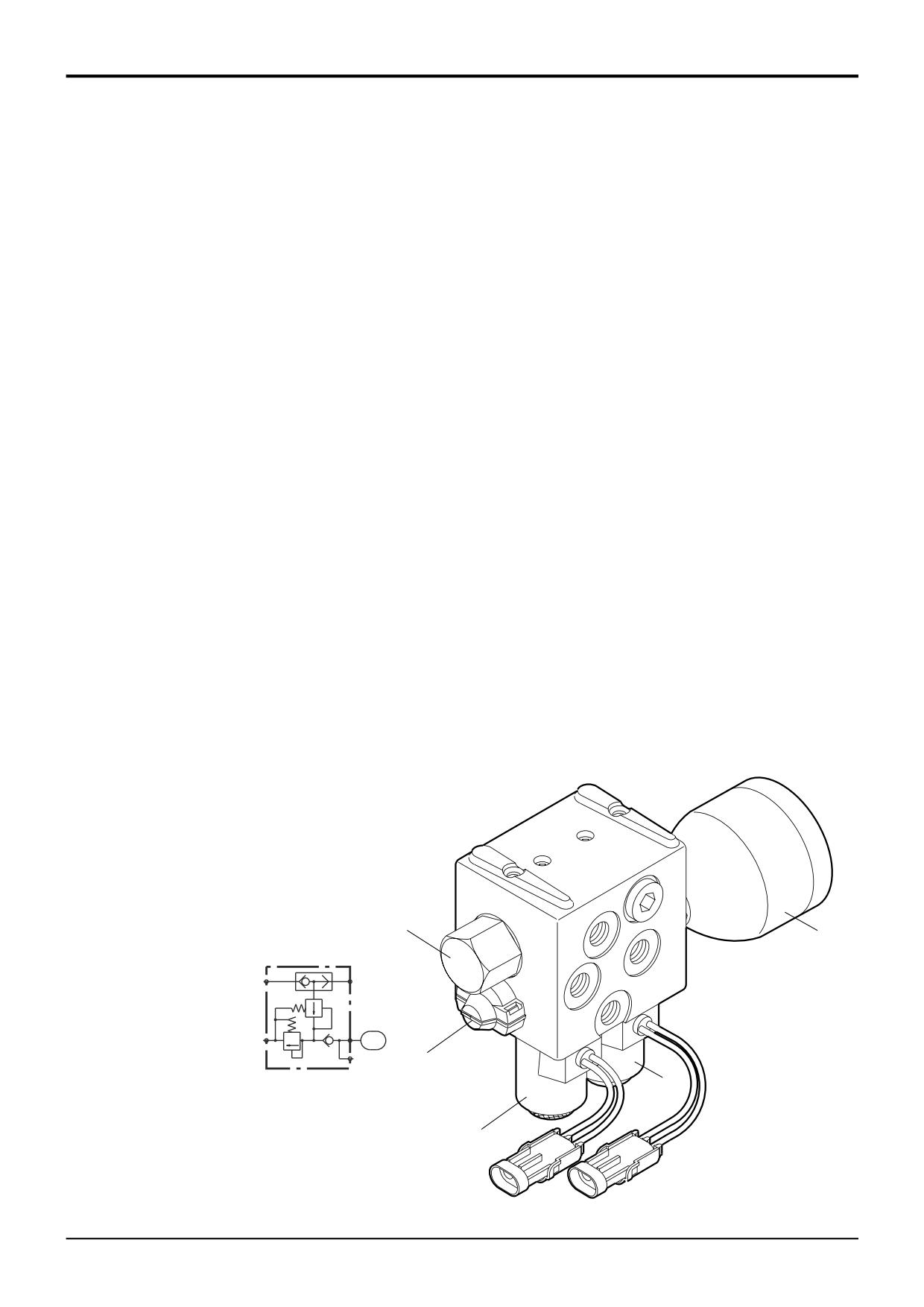
Servo Pressure Supply Valve - Description
The servo pressure supply valve is fitted with a pressure
regulating valve 1, a pressure relief valve 2 and two solenoid
valves 3 for servo pressure isolation.
The servo system is supplied from a single line tapped into
the hydraulic pump feed at the excavator valve block. The
pressure regulating valve 1 maintains servo pressure by
regulating the incoming supply pressure. The valve is non-
adjustable and is factory set with shims.
The pressure relief valve 2 is adjustable and limits the
maximum pressure, protecting the valve block from over-
pressurisation by opening and allowing excess pressure to
vent to tank.
Down stream of the pressure regulating valve is located the
servo accumulator 4 with its associated non return valve.
The accumulator traps and stores servo pressure to enable
the excavator spools to be operated for a limited period with
a stopped engine. This allows the excavator end to be
lowered safely to the ground should the engine stop.
The servo isolator solenoid valves 3 are energised by
proximity switches on the drivers seat. When the seat arm
rest is raised forward, the proximity switch closes and
energises the relevant isolator solenoid, directing servo
pressure to the particular joystick controller. When the arm
rest is folded back the proximity switch opens and the
isolation solenoid is de-energised, the isolation valve spool is
spring returned to the closed position isolating the supply to
the joystick controller.
1
Hydraulic symbol
4
P1
P2
T
PV
2
3
3
A404750
9803/3280
Issue 1
Section D
Controls
Section D
47 - 1
Precision Control (Servo)
47 - 1
Fault Finding
Introduction
The fault finding procedures are given in the form of flow
charts. There are a number of charts, each one dedicated to
a particular fault. The charts are designed to identify
possible causes by performing checks and where
applicable, specific tests. Having identified a cause the
suggested remedy is given. The charts are designed to
identify causes through a process of elimination, starting
with the simplest, most easily rectified faults.
When fault finding note the following:
1
Make sure that the hydraulic fluid is at the correct
working temperature (50oC, 122oF).
2
If hydraulic contamination is found be sure to remove
ALL debris, and if possible identify its origin. It may be
part of a component from elsewhere in the hydraulic
circuit.
3
Renew any seals such as ‘O’ rings when re-assembling
hydraulic components.
Fault Finding Charts:
Chart A - No Servo Controls (system fails to operate)
Chart B - All Backhoe Services Slow to Operate
Chart C - One Backhoe Service fails or is Slow to Operate
9803/3280
Issue 1
Section D
Controls
Section D
47 - 2
Precision Control (Servo)
47 - 2
Fault Finding
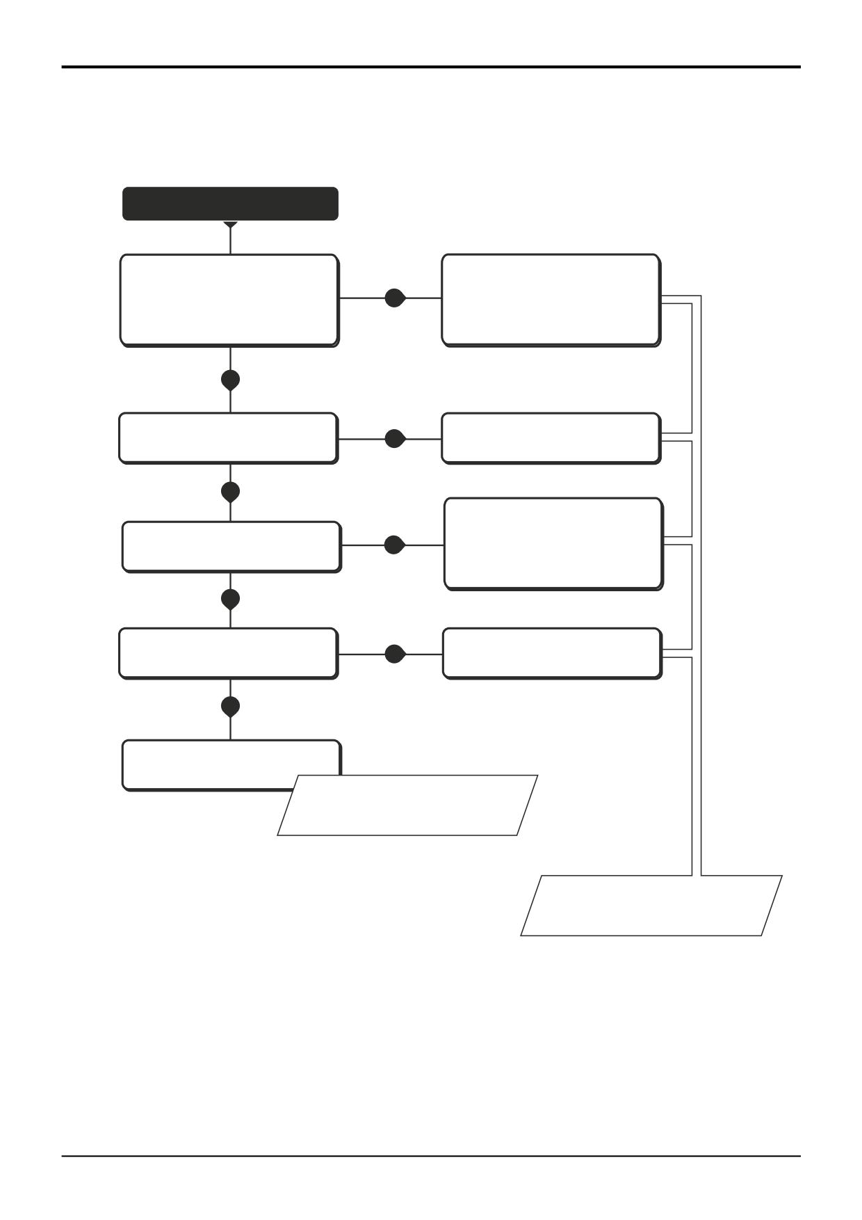
Chart A - No Servo Controls (system fails to operate)
START
Does the system operate if the seat is
Check the function of the seat mounted
locked in the opposite facing position?
proximity switches and condition of
YES
Check that the arm rests are
associated wiring for damage. Repair
raised forward (i.e. not pushed back)
or renew as applicable.
NO
Are the servo pressure isolation
Renew the solenoid coil(s).
YES
valve solenoid coils faulty?
NO
Inspect and test all relevant wiring
Are the relevant electrical
for damage and short circuits.
NO
fuses intact?
Repair as applicable. Renew the fuses.
YES
Is the wiring to the servo pressure
NO
Repair or renew as applicable.
isolation valve solenoid coils intact?
YES
Renew servo pressure isolation
valve cartridge.
Refer to Servo Pressure Supply Valve
- Dismantling and Assembly.
Refer to Electrical Operation
- Joystick Controller.
A405600
9803/3280
Issue 1
Section D
Controls
Section D
47 - 3
Precision Control (Servo)
47 - 3
Fault Finding
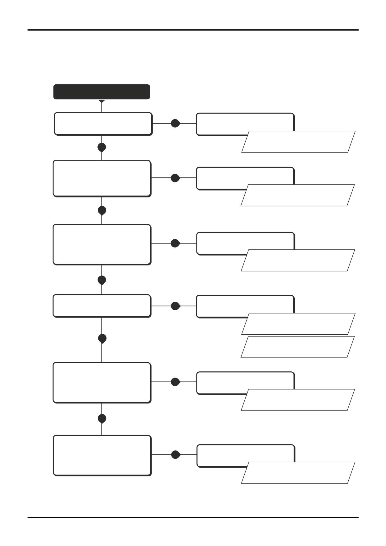
Chart B - All Backhoe Services Slow to Operate
START
Is the servo pressure low?
YES
Adjust as required.
Refer to Service Procedures
- Testing the Servo Pressure.
NO
Are the servo pressure isolation
valves operating correctly? Remove
Clean and renew components as
NO
the valve cartridges and check for
applicable.
signs of contamination or sticking.
Refer to Servo Pressure Supply Valve
- Dismantling and Assembly.
YES
Are the joystick controls worn?
Check the condition of the universal
YES
Repair or renew as applicable.
joint mechanism on the joystick
controllers.
Refer to Joystick Controllers -
Dismantling and Assembly.
NO
Is the load sense relief valve out of
YES
Adjust, repair or renew as required.
adjustment or defective?
Refer to Section E, Service
Procedures, Pressure Testing - Load
Sense Relief Valve.
NO
Refer to Section E, Excavator Valve
- Dismantling and Assembly.
Is the flushing valve piston in
the excavator valve inlet section
Clean and renew components as
YES
blocked open (return to tank)?
applicable.
Refer to Section E, Excavator Valve
- Dismantling and Assembly.
NO
Does the engine remain under load
after the spools are returned to neutral?
Clean and renew components as
Remove the flow regulator valve and
YES
applicable.
check for signs of contamination or
sticking. Check if the valve filter is
clogged.
Refer to Section E, Excavator Valve
- Dismantling and Assembly.
A405670
9803/3280
Issue 1
Section D
Controls
Section D
47 - 4
Precision Control (Servo)
47 - 4
Fault Finding
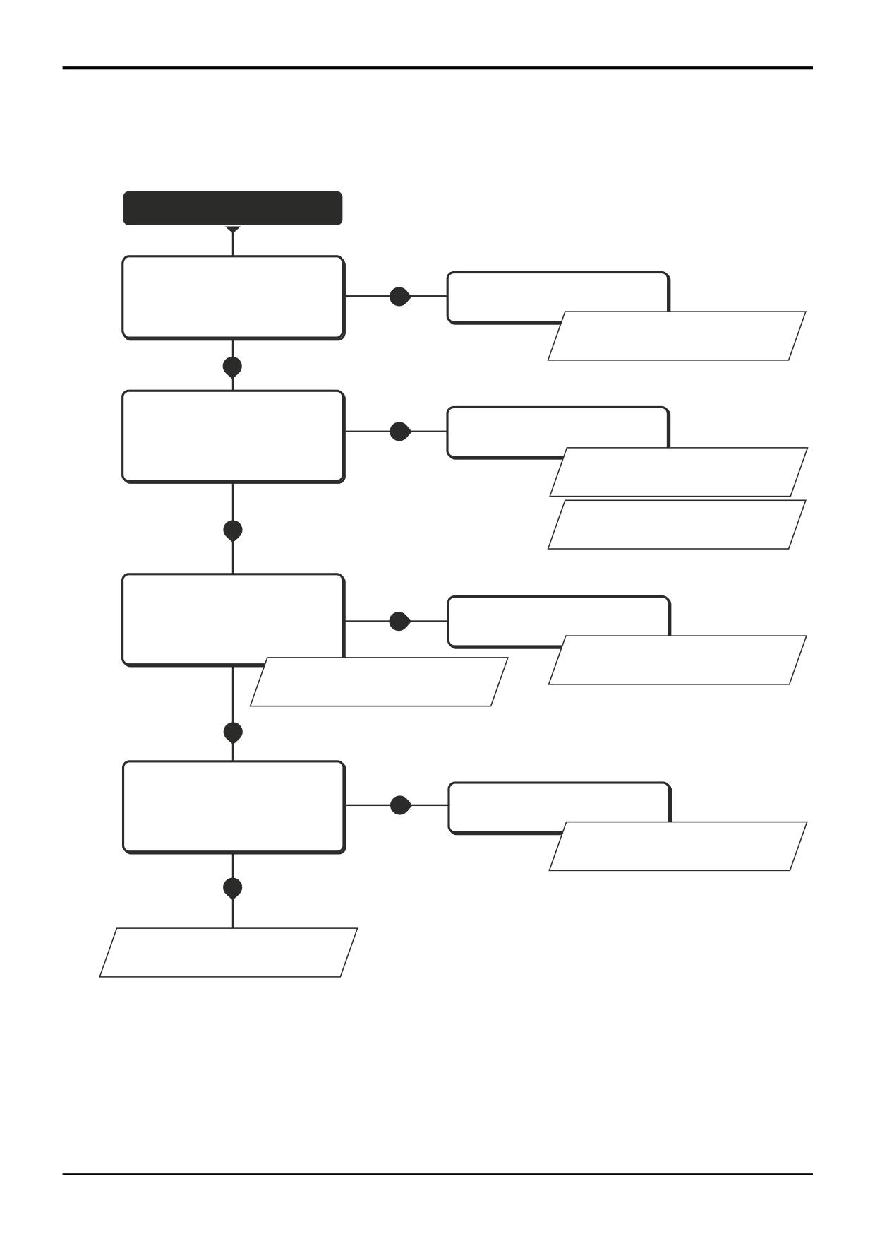
Chart C - One Backhoe Service fails or is Slow to Operate
START
Inspect the associated joystick
Clean and renew components as
controller valve capsule for signs of
NO
applicable.
wear, damage or contamination.
Is the valve in good working order?
Refer to Joystick Controllers -
Dismantling and Assembly.
YES
Is the associated auxiliary relief valve
YES
Adjust, repair or renew as required.
(ARV) out of adjustment or blocked
open (return to tank)?
Refer to Section E, Service
Procedures, Excavator Valve,
Pressure Testing - ARV's.
Refer to Section E, Excavator Valve
NO
- Dismantling and Assembly.
Is the associated pressure
Clean and renew components as
compensator blocked?
YES
applicable.
Test the pressure compensator network.
Refer to Section E, Excavator Valve
Refer to Section E, Service Procedures,
- Dismantling and Assembly.
Excavator Valve, Pressure Compensator
Network - Testing.
NO
Will the service hold a load normally?
Inspect the associated load hold check
Clean and renew components as
NO
valves and the service spool for signs
applicable.
of wear, damage or contamination.
Refer to Section E, Excavator Valve
- Dismantling and Assembly.
YES
Refer also to Section E, Hydraulics
Fault Finding, 'One hydraulic service
fails or is slow to operate'.
A405690
9803/3280
Issue 1
Section D
Controls
Section D
48 - 1
Precision Control (Servo)
48 - 1
Service Procedures
Testing the Servo Pressure
TBA
9803/3280
Issue 1
Section D
Controls
Section D
50 - 1
Precision Control (Servo)
50 - 1
Joystick Controllers
Removal and Replacement
! DANGER
Hydraulic fluid at system pressure can injure you. Before
disconnecting or connecting hydraulic hoses, stop the
engine and operate the controls to release pressure
trapped in the hoses. Make sure the engine cannot be
started while the hoses are open.
INT-3-1-11/1
Note that the procedure shows the left hand joystick
controller. The removal and replacement procedure for the
right hand joystick controller is identical.
Removal
A
1
Park the machine on firm level ground, engage the
parking brake and set the transmission to neutral.
Lower the attachments to the ground and stop the
engine.
Before attempting to remove a joystick controller, vent the
pilot circuit accumulator hydraulic pressure as follows:
D
2
With the operator seat locked in the rear facing position
and with the arm rests raised forward (for backhoe
operation), switch the starter to ON without starting the
engine. Operate the joystick controls several times to
vent the hydraulic pressure from the servo system and
backhoe rams. Turn the starter switch to the OFF
position and remove the key.
3
Remove the screws A (4 off) and lift off the top retaining
plate as shown.
4
Using a screwdriver, carefully prise out the plastic cap
B
B. Remove the screws C (2 off) and take off the lower
cover to reveal the connections at the valve block.
5
Disconnect the electrical harness connector for the
joystick handle switches.
C
6
Disconnect all hydraulic hoses from the valve block and
plug the ports to prevent ingress of dirt. Label each
hose before disconnecting to ensure correct
replacement. Plug hose ends to prevent ingress of dirt.
A405620
7
Carefully prise back the rubber gaiter D to reveal the
fixing bolts (4 off) securing the valve to the arm rest.
Remove the fixing bolts and lift the valve assembly from
the seat.
Replacement
Replacement is the reverse of the removal sequence.
Note: All hydraulic adaptors that are installed together with a
bonded sealing washer must also have JCB Threadseal
applied to the threads of the adaptor.
9803/3280
Issue 1
Section D
Controls
Section D
50 - 2
Precision Control (Servo)
50 - 2
Joystick Controllers
Dismantling and Assembly
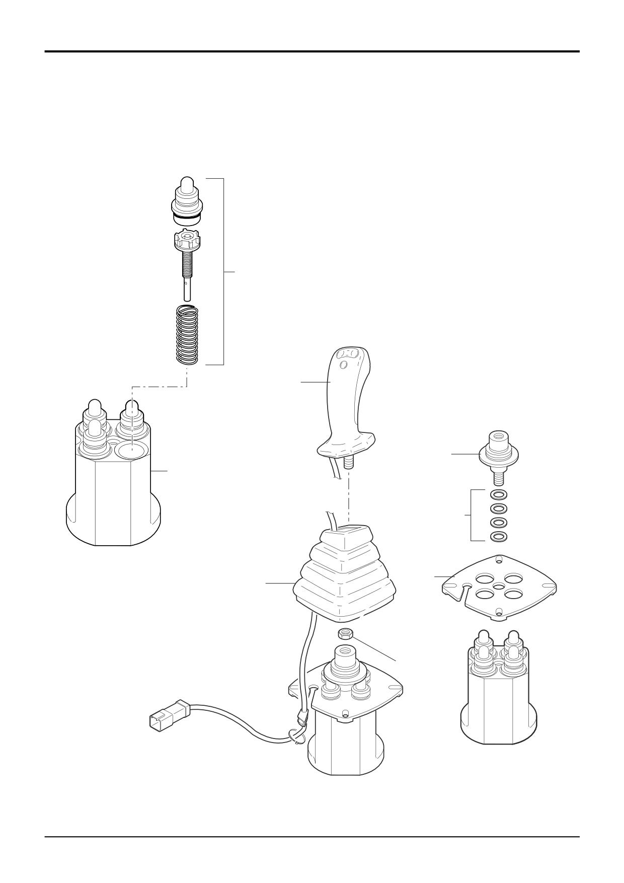
7
3
4
8
5
A404780
6
1
2
A404770
9803/3280
Issue 1
Section D
Controls
Section D
50 - 3
Precision Control (Servo)
50 - 3
Joystick Controllers
Dismantling and Assembly
Dismantling
The illustration shown on the opposite page is intended as a
Regulating Valve Assemblies
guide to dismantling. Be sure to note the location of all
Each of the regulating valve assemblies 7 can be removed
components when dismantling. Although some components
as shown. Care must be taken to ensure that the spool is
may appear to be identical they are not interchangeable.
not damaged when removing it from the valve body. Note
Make sure that components are assembled in their original
that all spools are similar in appearance but must not be
positions.
interchanged as they are matched to their bores. All spools
have the same centring and sealing components.
Great care should be taken when dismantling and
assembling a valve to avoid the following:-
• Contamination
• Damage to spools
• Damage to seal grooves
Any of the above may result in possible problems with the
operation of the valve.
1
Remove the joystick controller from the machine, refer
to Joystick Controller - Removal and Replacement.
2
Carefully prise back the rubber gaiter 1, loosen lock nut
2 and unscrew the handle 3.
3
Unscrew the universal joint assembly 4. Take care to
keep all the shims 5 together.
4
Remove the retaining plate 6. Carefully withdraw the
regulating valve assemblies 7 from the valve body 8.
Assembly
Assembly is the reverse of the dismantling sequence.
1
Clean the valve components in an appropriate solvent.
2
Renew all 'O' rings and back-up rings.
3
Lubricate parts with JCB Hydraulic Fluid before
assembling. Make sure that all the parts move freely.
Torque Settings
Item
Nm
kgf m
lbf ft
2
40
4.1
29.5
4
50
5.1
36.9
9803/3280
Issue 1
Section D
Controls
Section D
51 - 1
Precision Control (Servo)
51 - 1
Servo Pressure Supply Valve
Removal and Replacement
Replacement
! WARNING
Make the machine safe before working underneath it.
Replacement is the reverse of the removal sequence.
Park the machine on level ground, lower the arms. Apply
the parking brake, put the transmission in neutral and
After replacement check the valve pressure settings. Refer to
stop the engine. Chock both sides of all four wheels.
Service Procedures - Testing the Servo Pressure.
Disconnect the battery, to prevent the engine being
Note: All hydraulic adaptors that are installed together with a
started while you are beneath the machine.
bonded sealing washer must also have JCB Threadseal
GEN-1-2
applied to the threads of the adaptor.
! DANGER
Hydraulic fluid at system pressure can injure you. Before
disconnecting or connecting hydraulic hoses, stop the
engine and operate the controls to release pressure
trapped in the hoses. Make sure the engine cannot be
started while the hoses are open.
INT-3-1-11/1
Removal
1
Park the machine on firm level ground, engage the
parking brake and set the transmission to neutral.
Lower the attachments to the ground and stop the
engine.
Before attempting to remove the valve, vent the pilot circuit
accumulator hydraulic pressure as follows:
2
With the operator seat locked in the rear facing position
and with the arm rests raised forward (for backhoe
operation), switch the starter to ON without starting the
engine. Operate the joystick controls several times to
vent the hydraulic pressure from the servo system and
A
backhoe rams. Turn the starter switch to the OFF
position and remove the key.
3
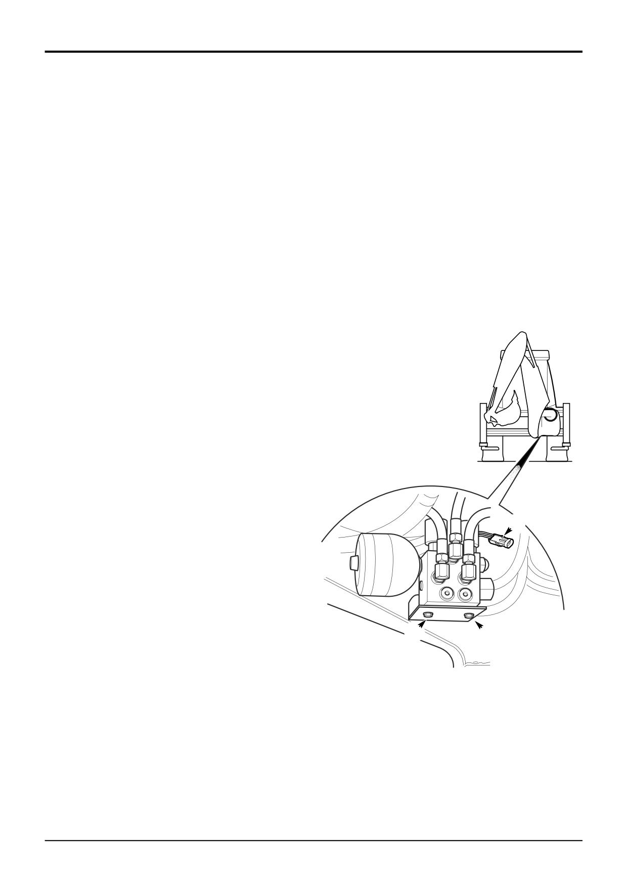
Working underneath the rear of the machine as shown,
disconnect the electrical harness connectors A at the
solenoids. Label each connector before disconnecting
to ensure correct replacement.
4
Disconnect all hydraulic hoses from the valve block and
B
B
plug the ports to prevent ingress of dirt. Label each
hose before disconnecting to ensure correct
A405610
replacement. Plug hose ends to prevent ingress of dirt.
5
Take hold of the valve assembly, loosen and remove the
fixing bolts B securing the valve to the chassis. Lift the
valve assembly from the machine.
9803/3280
Issue 1
Section D
Controls
Section D
51 - 2
Precision Control (Servo)
51 - 2
Servo Pressure Supply Valve
Dismantling and Assembly
1
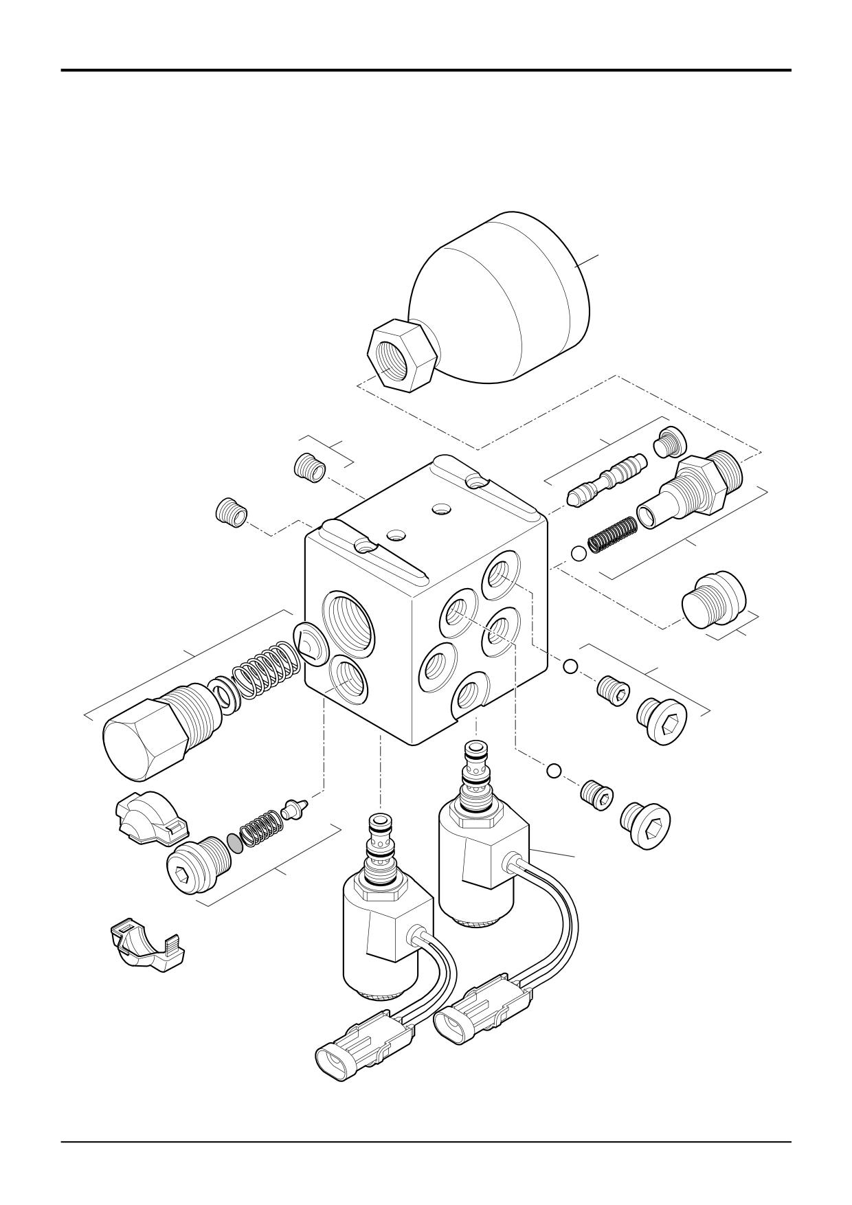
2A
2
3
4
5
2B
7
6
A404760
9803/3280
Issue 1
Section D
Controls
Section D
51 - 3
Precision Control (Servo)
51 - 3
Servo Pressure Supply Valve
Dismantling and Assembly
Dismantling
The illustration shown on the opposite page is intended as a
Accumulator
guide to dismantling. Be sure to note the location of all
The accumulator 1 can be removed as shown. Take great
components when dismantling. Although some components
care when handling the accumulator, the unit is pre-charged
may appear to be identical they are not interchangeable.
with nitrogen gas and further dismantling of the accumulator
Make sure that components are assembled in their original
should not be attempted. The adaptor assembly 3
positions.
incorporates a non-return valve with a spring and ball as
shown.
Great care should be taken when dismantling and
assembling a valve to avoid the following:-
Regulating Valve Assembly
The regulating valve assembly 5 can be removed as shown.
• Contamination
The valve is non-adjustable and is factory set with shims.
Take care to keep all the shims together.
• Damage to spools
• Damage to seal grooves
Pressure Relief Valve
The pressure relief valve 6 can be removed as shown.
Any of the above may result in possible problems with the
operation of the valve.
Solenoid Isolation Valves
The solenoid isolation valves 7 can be removed as shown. It
1
Remove the servo pressure supply valve from the
is possible to remove the valve cartridges for cleaning or
machine, refer to Servo Pressure Supply Valve -
resealing without removing the complete valve from the
Removal and Replacement.
machine. If there is evidence of damage to the valve or its
seat caused by debris then the cartridge must be renewed.
Note: The illustration depicts a complete strip down, but to
carry out specific servicing/repairs, e.g. renewal of one of the
Note: If removing components from a valve block that is
solenoids, it is only necessary to dismantle the relevant
fitted on a machine the pilot circuit accumulator pressure
components.
must be vented first. With the operator seat locked in the
rear facing position and with the arm rests raised forward
Assembly
(for backhoe operation), switch the starter to ON without
starting the engine. Operate the joystick controls several
Assembly is the reverse of the dismantling sequence.
times to vent the hydraulic pressure from the servo system
and backhoe rams. Turn the starter switch to the OFF
1
Clean the valve components in an appropriate solvent.
position and remove the key.
2
Renew all 'O' rings and back-up rings.
3
Lubricate parts with JCB Hydraulic Fluid before
assembling. Make sure that all the parts move freely.
Torque Settings
Item
Nm
kgf m
lbf ft
1
100
10.2
73.8
2
10
1
7.4
2A
10
1
7.4
2B
30
3
22.1
3
100
10.2
73.8
4
100
10.2
73.8
5
150
15.3
110.6
6
100
10.2
73.8
7
15-20
1.5-2
11-14.8
9803/3280
Issue 1
Section D
Controls
Section D
60 - 1
Control Rods and Linkages
60 - 1
Dismantling and Assembly
Loader Valve Controls
G
D
E
K
F
Locking
K
Pin
H
A404660
X
C
J
B
A
A404500
9803/3280
Issue 1
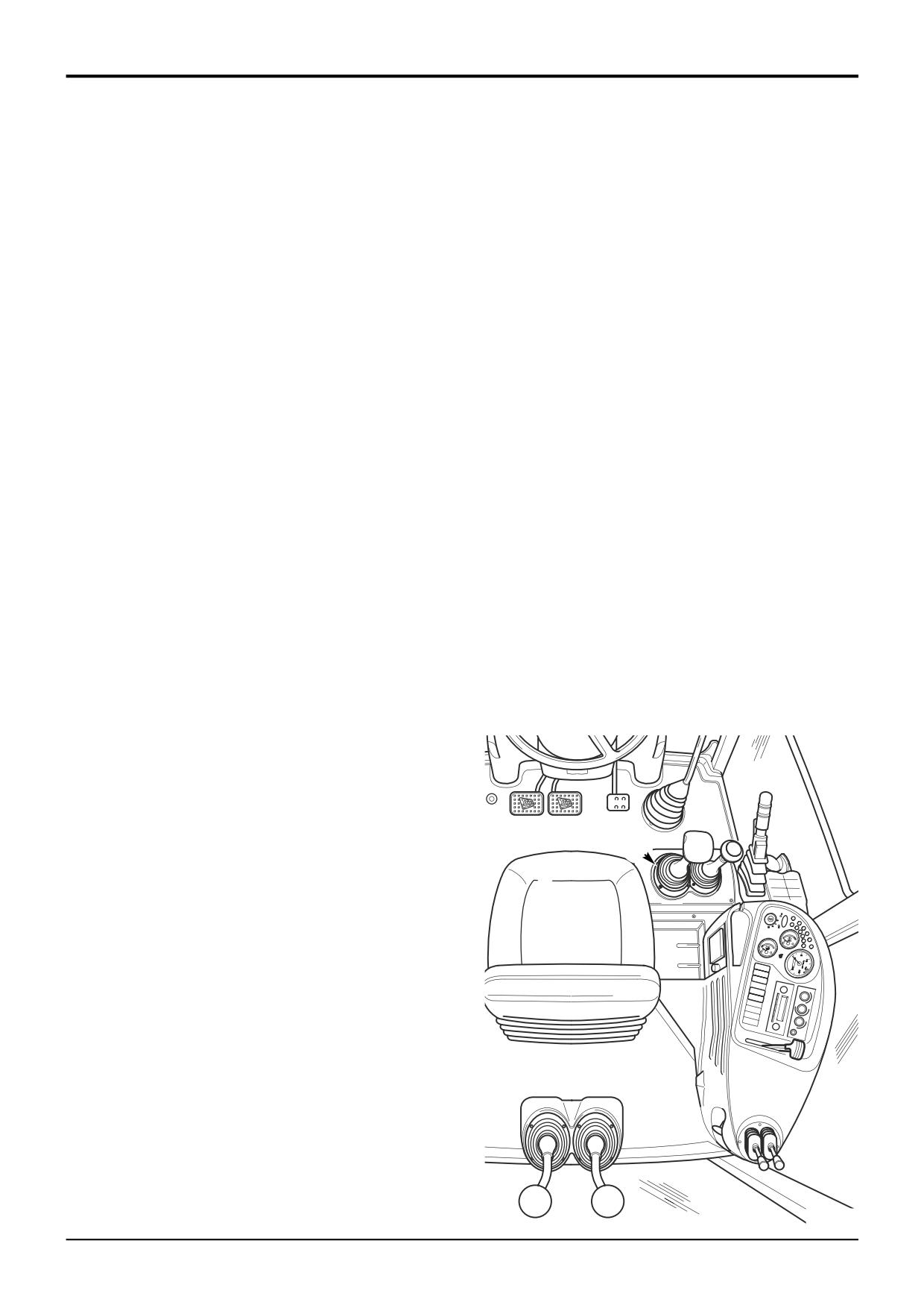
Section D
Controls
Section D
60 - 2
Control Rods and Linkages
60 - 2
Dismantling and Assembly
9
Thread the transmission dump switch cable through the
Loader Valve Controls
loader control lever and fit the wires/pins into the
electrical connector. Couple the connector to the
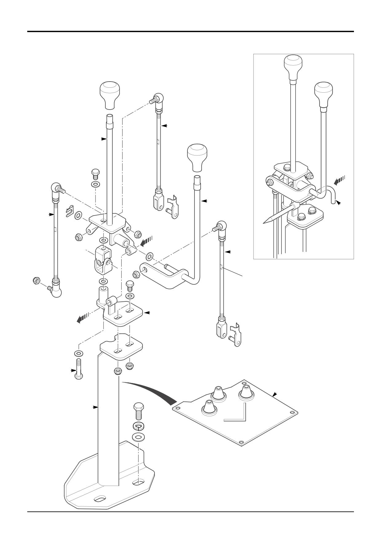
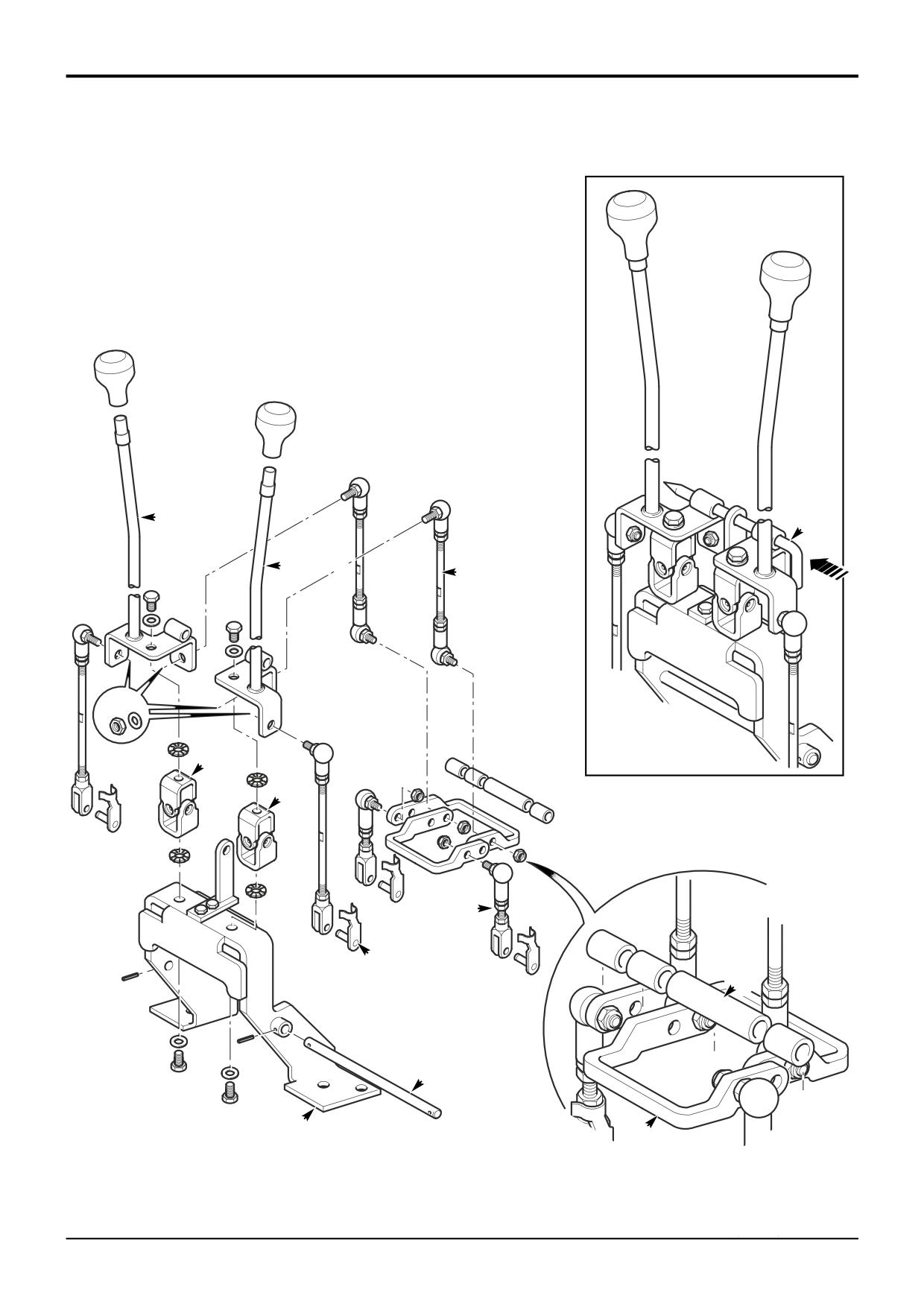
The illustration on the adjacent page shows the control rods
chassis harness and fit the control lever knobs.
and linkages for the loader control valve and is intended as a
guide to the dismantling and assembly.
10
Connect the battery, check that the controls and
transmission dump switch operate correctly.
Dismantling
11
Refit the rubber cover B and the console panels around
1
Park the machine on firm level ground, apply the
the loader levers.
parking brake. Lower the loader arms and excavator to
the ground, switch OFF the engine and remove the
Adjustment
starter key. Disconnect the battery.
1
Fit the control lever locking pin K as shown, tighten bolt
2
Working in the cab, remove the console panels
J when aligned.
surrounding the loader levers as shown at Z.
Note: If there is no lever locking pin with the machine use a
3
Uncouple the transmission dump switch electrical
suitable diameter metal bar.
connector and remove the wires from the connector.
Use a screwdriver to release the wires/pins from the
2
Adjust the control rods F and G until the locking pin is a
connector, alternatively cut the wires and re-solder on
sliding fit, then tighten the control rods lock nuts.
assembly.
Note: Make sure there is an equal amount of thread at each
4
Remove the control lever knobs and gaiters.
end of the control rod.
5
Disconnect the control rods from the loader valve
3
Adjust the auxiliary control rod H until the auxiliary lever
spools. Remove the bolts securing the complete lever
E aligns with loader lever D, then tighten the control rod
assembly to the chassis and withdraw the control levers
lock nuts.
and mounting bracket through the floor aperture.
4
Remove the lever locking pin K.
Assembly
Assembly is the reverse of the dismantling sequence.
1
Bolt the mounting bracket A to the chassis.
2
Fit the rubber cover B over the mounting bracket, make
sure it is fitted the correct way round. Do not fix it to the
floor at this stage.
3
Bolt the mounting plate C to mounting bracket as
shown.
Z
4
Assemble the loader lever D and auxiliary lever E
together, with the washers and retaining clip as shown.
5
Fit the control rods F, G and H to the lever assembly.
Ensure that the locking flats X are at the top.
Note: If necessary, loosen the lock nuts and rotate the end
fittings to give equal amounts of adjustment (thread) at each
end of the control rod.
6
Fit the lever assembly to the mounting plate C as
shown, do not tighten the bolt J at this stage.
7
Thread the control rods through the rubber cover B and
connect them to the loader valve spools.
8
Adjust the control rods as necessary, see Adjustment.
After the control rods are adjusted fit the gaiters over
the control levers.
A394410
9803/3280
Issue 1
Section D
Controls
Section D
61 - 1
Control Rods and Linkages
61 - 1
Dismantling and Assembly
Excavator Valve Controls (JCB + Pattern)
Locking
Pin
F
L
G
J
H
H
E
K
C
D
A
B
A404810
9803/3280
Issue 1
Section D
Controls
Section D
61 - 2
Control Rods and Linkages
61 - 2
Dismantling and Assembly
6
Thread the rear horn switch cable through the control
Excavator Valve Controls
lever and fit the wires/pins into the electrical connector.
Couple the connector to the chassis harness and fit the
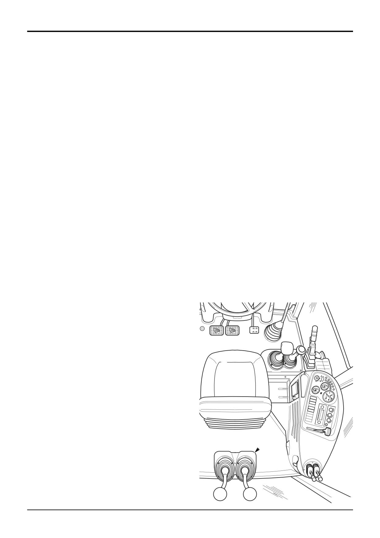
The illustration on the adjacent page shows the control rods
control lever knobs.
and linkages for the excavator control valve and is intended
as a guide to the dismantling and assembly. Note JCB +
7
Connect the battery, check that the controls and rear
pattern controls shown.
horn switch operate correctly.
Dismantling
8
Refit the console panels around the excavator levers.
1
Park the machine on firm level ground, apply the
Adjustment
parking brake. Lower the loader arms, move the
excavator to the R.H. side of the machine and lower to
1
Fit the control lever locking pin L as shown.
the ground. Switch OFF the engine and remove the
starter key. Disconnect the battery.
Note: If there is no lever locking pin with the machine use a
suitable diameter metal bar.
2
Working in the cab, remove the console panels
surrounding the excavator levers as shown at Z.
2
Adjust the control rods until the locking pin is a sliding
fit, then tighten the control rods lock nuts.
3
Uncouple the rear horn switch electrical connector and
remove the wires from the connector. Use a screwdriver
Note: Make sure there is an equal amount of thread at each
to release the wires/pins from the connector,
end of the control rod.
alternatively cut the wires and re-solder on assembly.
3
Remove the lever locking pin L.
4
Remove the control lever knobs and gaiters.
5
Disconnect the control rods from the excavator valve
spools. Remove the bolts securing the complete lever
assembly to the excavator valve mounting plate and
withdraw the control levers and mounting bracket
through the floor aperture.
Assembly
Assembly is the reverse of the dismantling sequence.
1
Bolt the mounting bracket A to the excavator valve
mounting plate.
2
Assemble the pivot levers B and spacers C to the
mounting bracket and insert the pivot shaft D. Fit the
short control rods E (2 off) to the pivot lever assembly
as shown.
3
Assemble the excavator levers F and G to the mounting
bracket together with the universal joints H. Fit the
longer control rods J (4 off) to the lever assembly as
shown.
Note: If necessary, loosen the lock nuts and rotate the end
fittings to give equal amounts of adjustment (thread) at each
end of the control rod.
4
Connect the control rods to the excavator valve spools
with the clevis pins K.
Z
5
Adjust the control rods as necessary, see Adjustment.
After the control rods are adjusted fit the gaiters over
the control levers.
A394410
9803/3280
Issue 1
Section D
Controls
Section D
70 - 1
Control Cables
70 - 1
Removal and Replacement
Cab Heater Controls
X
Y
R
C
D
S
R
X
T
Z
0
E
A404491
9803/3280
Issue 1
Section D
Controls
Section D
70 - 2
Control Cables
70 - 2
Removal and Replacement
Cab Heater Controls
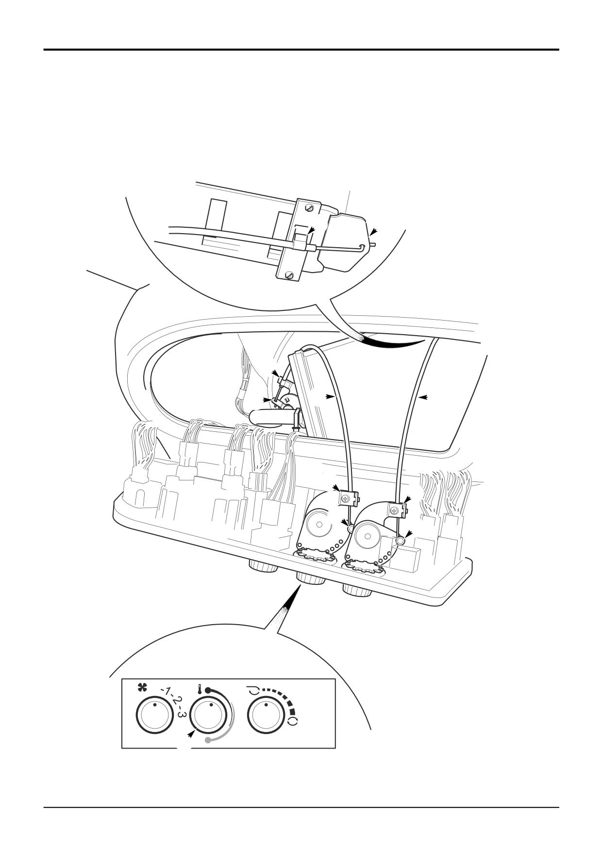
The cab heater controls A and associated cables are housed
in the R.H. side console as shown.
There are two control cables which operate the re-circulation
vent and the hot water valve. Both the cables can be
accessed by removing the side console instrument panel.
Removal
1
Park the machine on firm level ground, apply the
parking brake. Lower the loader arms and excavator to
the ground, switch OFF the engine and remove the
starter key.
B
2
Remove the fixing B at the top of the instrument panel
A
and carefully lift the panel forward to reveal the
connections at the back.
3
Disconnect the temperature control cable C by
releasing the cable outer sheath from the clips R at
each end, and unhooking the cable from the water valve
lever S and from the pin T at the control knob.
4
Disconnect the re-circulation vent cable D by releasing
the cable outer sheath from the clips X at each end, and
unhooking the cable from the vent Y and from the pin Z
at the control knob.
A394410
Replacement
Replacement is the reverse of the removal sequence.
After fitting the cables, operate the heater controls and
check that they function correctly.
Adjustment
If the control cable C is not correctly assembled it is possible
that the heater cannot be turned fully off.
To ensure that the heater can be turned fully OFF, the
temperature control cable C should be adjusted so that the
water valve will close FULLY within the range of movement
of the control knob as follows:
1
Set the water valve control lever S to the fully closed
position.
2
Turn the heater control knob E a small amount
clockwise from the closed position, i.e. a fraction before
the cold position on the decal as shown.
3
Tighten the cable clips R to clamp the cable outer
sheath.
4
Check the heater control range of movement and that
the water valve can be fully closed by turning the knob.
9803/3280
Issue 1