JCB 3CX, 4CX, 214e, 214, 215, 217 & VARIANTS Backhoe Loader. Service Manual - page 11
Section D
Controls
Section D
71 - 1
Control Cables
71 - 1
Removal and Replacement
Stabiliser Controls
F
H
G
A404700
E
D
C
B
A404730
9803/3280
Issue 1
Section D
Controls
Section D
71 - 2
Control Cables
71 - 2
Removal and Replacement
Stabiliser Controls
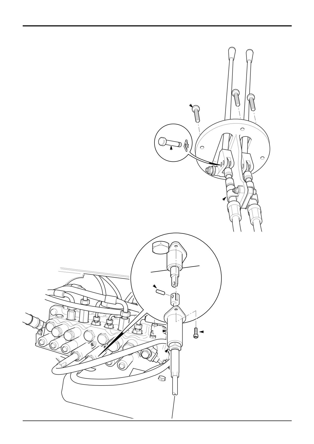
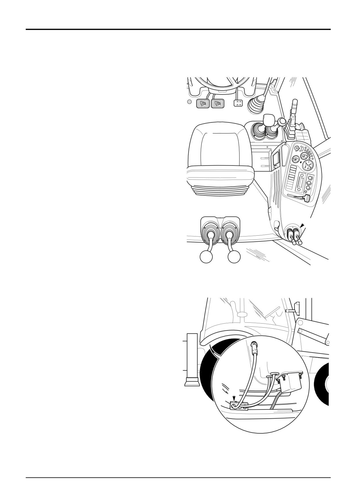
The stabiliser controls A and associated cables are housed
in the R.H. side console as shown.
There are two control cables which operate the R.H. and
L.H. stabiliser control valves on the excavator valve block.
Note the routing of the existing cables and route the new
cable(s) in the same way.
Removal
1
Park the machine on firm level ground, apply the
parking brake. Lower the loader arms and excavator to
the ground, switch OFF the engine and remove the
starter key.
2
Working under the machine at the excavator valve,
undo the locknut B. Remove the screws C and slide
back the housing D to reveal the clevis as shown.
Remove the clevis pin E to release the cable from the
spool.
3
Feed the end of the cable back underneath the cab to
A
the rear wheel arch on the R.H. side of the machine and
release the cable from the clamp assembly at position X
as shown.
4
Working in the cab, remove the fixings F from around
A394410
the base of the control levers and carefully withdraw the
lever assembly from the side console to reveal the
cables connected on the underside.
5
Remove the clamp G securing the cables to the
bracket. Remove the spring clip and clevis pin H to
release the cable.
6
From inside the side console, carefully pull the cable up
into the cab through the aperture in the cab floor.
Replacement
Replacement is the reverse of the removal sequence.
After fitting the cable(s), operate the controls and check that
the stabilisers function correctly.
X
A405180
9803/3280
Issue 1
Section D
Controls
Section D
72 - 1
Control Cables
72 - 1
Removal and Replacement
Boom Lock Cable
D
X
A405180
A
A394410
B
2
C
3
6
1
5
4
A404510
9803/3280
Issue 1
Section D
Controls
Section D
72 - 2
Control Cables
72 - 2
Removal and Replacement
Boom Lock Cable
Boom Stop Setting
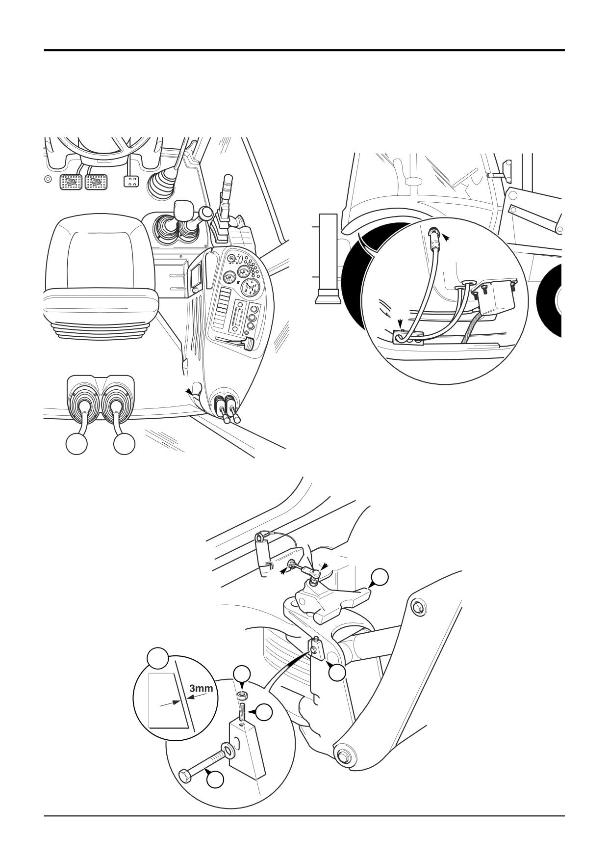
The boom lock control A and associated cable is housed in
The boom stop block should be set as follows:
the R.H. side console as shown.
1
Lightly secure the boom stop block 1 in its lowest
Note the routing of the existing cable and route the new
position.
cable in the same way.
2
Raise the boom lock 2 using the control knob in the
Removal
cab.
1
Park the machine on firm level ground, apply the
3
Fully raise the boom (i.e. the boom ram fully retracted)
parking brake. Lower the loader arms and excavator to
and engage the boom lock using the control knob in the
the ground, switch OFF the engine and remove the
cab.
starter key.
4
With the engine switched OFF, operate the excavator
2
Working at the boom, remove the cable ball stud B from
control levers several times to vent any resisdual
the boom lock casting.
pressure from the boom ram.
3
Loosen the lock nut and disconnect the bulkhead fitting
5
Adjust the boom stop block 1 until there is 3 mm (1/8
C from the bracket. Feed the end of the cable back
in.) gap between the stop and the boom profile as
underneath the cab to the rear wheel arch on the R.H.
shown at 3.
side of the machine and release the cable from the
clamp assembly at position X as shown. Remove the
6
Tighten clamping bolt 4. Tighten grubscrew 5 and lock
spring clip D from the outer sleeve.
nut 6.
4
Working in the cab, unscrew the knob and lock nut from
7
Switch ON the engine. Fully raise the boom (i.e. the
the boom lock control A. Remove the fixings from the
boom ram fully retracted) and raise the boom lock using
side console panel and carefully lift up the rear corner
the control knob in the cab.
of the side console panel over the boom lock control
outer sleeve.
8
If the boom lock does not release readjust the stop
block as follows:
5
With the rear corner of the side console panel lifted up,
carefully pull the boom lock cable up into the cab
a Loosen the lock nut 6 and slacken the grubscrew 5
through the aperture in the cab floor.
a further half turn.
Replacement
b Loosen clamping bolt 4 and reposition the stop
block. Retighten bolt 4 and lock the grubscrew.
Replacement is the reverse of the removal sequence.
9
Operate the boom and check that the boom lock will
1
After fitting the cable, with the control knob pressed
engage and disengage correctly using the control knob
down adjust the bulkhead fitting C to take up any slack
in the cab.
in the cable. The cable should be tight but must not lift
the boom lock from its fully down position.
Torque Settings
2
Operate the boom and check that the boom lock will
Item
Nm
kgf m
lbf ft
engage and disengage correctly using the control knob
E
476
48
352
in the cab. Check the boom stop setting, see Boom
Stop Setting.
9803/3280
Issue 1
Section D
Controls
Section D
73 - 1
Control Cables
73 - 1
Removal and Replacement
Engine Throttle Cable
D
C
A404690
K
J
K
E
F
G
E
A404680
A404670
9803/3280
Issue 1
Section D
Controls
Section D
73 - 2
Control Cables
73 - 2
Removal and Replacement
Engine Throttle Cable
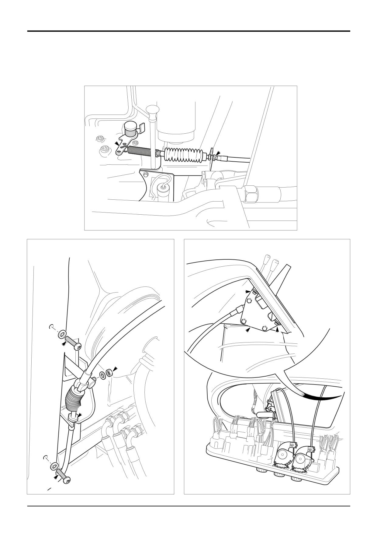
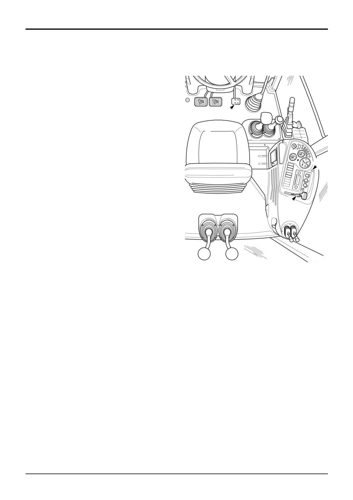
The engine throttle cable is routed from the L.H. side of the
engine compartment to connect with the footpedal A at the
engine compartment bulkhead, and to the hand throttle lever
B housed in the R.H. side console as shown.
A
Removal
1
Park the machine on firm level ground, apply the
parking brake. Lower the loader arms and excavator to
the ground, switch OFF the engine and remove the
starter key.
2
Open the bonnet and remove the engine side covers.
H
3
At the L.H. side of the engine compartment, disconnect
the throttle cable by loosening the lock nut C and
unhooking the cable from the fuel injector pump lever D
as shown. Feed the end of the cable back across the
engine compartment to the bulkhead on the R.H. side.
B
4
Working at the R.H. side of the engine compartment at
the bulkhead, remove the screws E and ease back the
rubber bulkhead cover to reveal the end of the
footpedal lever as shown. Remove the nut F and
disconnect the cable pivot block from the footpedal.
Loosen the lock nut G and release the cable from the
bracket. Feed the cable back underneath the cab to the
rear wheel arch on the R.H. side of the machine.
A394410
5
Working in the cab, remove the fixing H at the top of the
instrument panel and carefully lift the panel forward to
reveal the hand throttle lever and mounting bracket
assemby J inside the side console as shown.
6
Remove the hand throttle lever knob. Remove the
screws K, taking hold of the hand throttle lever
assembly withdraw the handle through the slot in the
panel.
7
From inside the side console, carefully pull the cable up
into the cab through the aperture in the cab floor.
Replacement
Replacement is the reverse of the removal sequence.
After fitting the cable, operate the hand and foot throttle
controls and check that they function correctly.
9803/3280
Issue 1
Section D
Controls
Section D
74 - 1
Control Cables
74 - 1
Removal and Replacement
Auxiliary Footpedal Cable
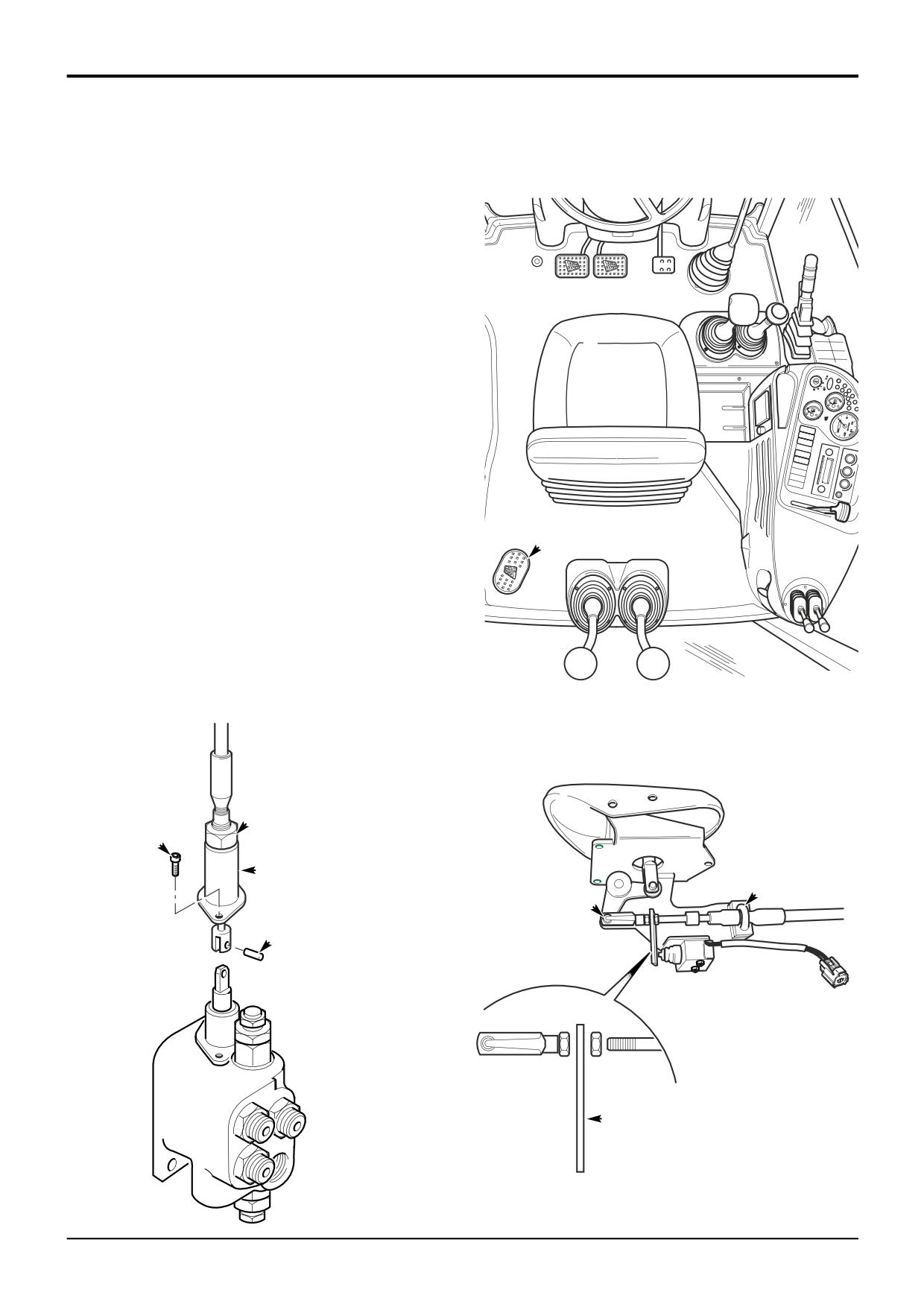
The auxiliary footpedal control A is mounted in the cab floor
as shown. The cable operates the auxiliary control valve
located adjacent to the excavator valve. The cable is
accessible underneath the rear L.H. corner of the cab.
Note the routing of the existing cable and route the new
cable in the same way.
Removal
1
Park the machine on firm level ground, apply the
parking brake. Lower the loader arms and excavator to
the ground, switch OFF the engine and remove the
starter key.
2
Working at the rear of the machine at the auxiliary valve,
undo the locknut B. Remove the screws C and slide
back the housing D to reveal the clevis as shown.
Remove the clevis pin E to release the cable.
A
3
At the footpedal remove the U-clamp F securing the
cable to the bracket. Remove the spring clip G to
release the cable. If the cable is to be replaced, remove
and retain the microswitch operating tab H from the old
cable as shown.
Replacement
A394410
Replacement is the reverse of the removal sequence.
B
C
D
F
G
E
H
A404720
A404710
9803/3280
Issue 1
Section E
Hydraulics
Section E
i
i
Contents
Page No.
Service Tools
1-1
Technical Data
Hydraulic Pumps
Fixed Flow
2-1
Variable Flow
2-3
Relief Valve Pressures
Loader Valve - Fixed Flow
2-4
Loader Valve - Precision Control (Servo)
- Machines up to serial no. 931159
2-5
- Machines from January 2003
2 - 5A
Loader Valve - Variable Flow
2-7
Excavator Valve - Fixed Flow
2-8
Excavator Valve - Precision Control (Servo)
- Machines up to serial no. 931159
2 - 10
- Machines from January 2003
2 - 10A
Auxiliary Valve - Fixed Flow
2 - 11
Smooth Ride System
2 - 13
Basic System Operation
Component Location and Neutral Circuit Descriptions
Fixed Flow - Single Pump
3-1
- Double Pump
3-3
Variable Flow
3-7
Introduction to Hydraulic Schematic Symbols
3 - 10
Circuit Schematics
Fixed Flow
3 - 20
Variable Flow
3 - 26
Precision Control (Servo)
- Machines up to serial no. 931159
3 - 31
- Machines from January 2003
3 - 33
Circuit Descriptions
Hydraulic Pump - Fixed Flow
Single Pump Operation
5-1
Double Pump Operation
5-1
Hydraulic Pump - Variable Flow
Operation
5-3
Pressure/Flow Regulator Valve
5-5
Loader Valve
Manual Control
- Neutral Circuit
6-1
- Unloader Operation
6-1
- Hydraulic Speed Control (HSC)
6-3
- Load Hold Check Valves Operation
6-5
- Arms Lower
6-7
- Float
6-7
- Auxiliary Relief Valve (ARV) Operation
6-9
- Main Relief Valve (MRV) Operation
6 - 11
9803/3280
Issue 4*
Section E
Hydraulics
Section E
ii
ii
Contents
Page No.
Loader Valve - Variable Flow
Operation
7-1
Priority Inlet Section Operation
7-2
Auxiliary Spool
7-4
Loader Shovel Spool
7-5
Loader Lift Spool
7-6
Shuttle Valve Signal Network
7-7
Excavator Valve
Manual Control
- Neutral Circuit
8-1
- Load Hold Check Valves Operation
8-3
- One Way Restrictor Operation
8-5
- Slew Operation
8-5
- Slew ARV and Anti Cavitation Operation
8-7
- Auxiliary Relief Valve (ARV) Operation
8-7
- Pilot Operated Pressure Relief Valve Operation
8-9
- Hydraclamp Valve Operation
8 - 11
Precision Control (Servo)
- Machines up to serial no. 931159
8 - 13
Hydraclamp Valve Operation
8 - 17
- Machines from January 2003
8 - 18
Smooth Ride System
10 - 1
Hose Burst Protection Valves (if fitted)
Boom & Dipper Operation
11 - 1
Loader Operation
11 - 5
Fault Finding
Hydraulic System
Fixed Flow
15 - 1
Variable Flow
15 - 10
Smooth Ride System
15 - 12
Service Procedures
Hydraulic Contamination
20 - 1
Fixed Flow Pumps
Flow and Pressure Testing
21 - 1
Variable Flow Pumps
Flow and Pressure Testing
22 - 1
Regulator Valve Adjustment
22 - 5
Renewing Drive Shaft Seal
22 - 7
Shuttle Valve Signal Network - Testing
22 - 8
Loader Valve - Pressure Testing
Main Relief Valve (MRV)
23 - 1
Unloader Valve
23 - 2
Hydraulic Speed Control (HSC)
23 - 3
Auxiliary Relief Valves (ARV's)
23 - 5
Excavator Valve - Pressure Testing
Auxiliary Relief Valves (ARV's)
23 - 9
Excavator Valve - Precision Control (Servo)
- Machines up to serial no. 931159
Pressure Testing -
Load Sense Drain Regulator and Relief Valve
23 - 10
9803/3280
Issue 4*
Section E
Hydraulics
Section E
iii
iii
Contents
Page No.
Excavator Valve - Precision Control (Servo)
- Machines from January 2003
Pressure Testing - Load Sense Relief Valve
23 - 11
Pressure Compensator Network - Testing
23 - 12
Ram Creep Tests - All Services
24 - 1
Quick Release Couplings
Connecting & Disconnecting
25 - 1
Smooth Ride System
Charging/Discharging the Accumulator
26 - 1
Hose Burst Protection Valves (if fitted)
Checking
27 - 1
Lowering a Load - In a Failure Condition
27 - 1
Pressure Testing - Loader Lift Ram
27 - 2
Main Pump
Fixed Flow
Removal and Replacement
30 - 1
Dismantling and Assembly
31 - 1
Variable Flow
Dismantling and Assembly
35 - 1
Loader Valve - Fixed Flow
Removal and Replacement
Manual Control
50 - 1
Dismantling and Assembly
Main Relief Valve (MRV)
50 - 6
Auxiliary Relief Valves (ARV’s)
50 - 8
Unloader Valve
50 - 10
Standard Spool - Manual
50 - 12
Float Spool - Manual
50 - 14
Electric Detent Spool - Manual
50 - 16
Bolt on Auxiliary Spool Section
50 - 24
- Auxiliary Relief Valves
50 - 26
Precision Control (Servo)
- Machines from January 2003
51 - 1
Standard Spool
51 - 3
Electric Detent Spool
51 - 5
Mechanical Detent Spool
51 - 7
Loader Valve - Variable Flow
Removal and Replacement
55 - 1
Dismantling and Assembly
Priority Inlet Section
55 - 2
Auxiliary Spool
55 - 4
Loader Shovel Spool
55 - 6
Loader Lift Spool
55 - 8
Fitting Spool Seal
55 - 10
9803/3280
Issue 4*
Section E
Hydraulics
Section E
iv
iv
Contents
Page No.
Excavator Valve
Removal and Replacement
Manual Control
60 - 1
Variable Flow
60 - 4
Precision Control (Servo)
60 - 6
Dismantling and Assembly
Manual Control
61 - 1
- Auxiliary Relief Valves (ARV’s)
61 - 3
- Hydraclamp Valve (Sideshift Machines)
61 - 5
- Hoses and Pipes
61 - 6
Precision Control (Servo)
- Machines up to serial no. 931159
62 - 1
Drain Regulator and Relief Valve
62 - 3
Hydraclamp Valve
62 - 5
- Machines from January 2003
62 - 20
Flow Regulator Valve
62 - 22
Load Sense Relief Valve
62 - 23
Auxiliary Relief Valves (ARV’s)
62 - 24
Anti-cavitation Valve
62 - 25
Hose Burst Protection Valves (if fitted)
Removal and Replacement
70 - 1
Dismantling and Assembly
70 - 2
Hydraulic Rams
Removal and Replacement
Loader Lift Ram
75 - 1
Loader Shovel Ram
76 - 1
Slew Ram
77 - 1
Stabiliser Ram - Sideshift
78 - 1
Stabiliser Ram - Centremount
78 - 3
Dipper Ram
79 - 1
Bucket Crowd Ram
80 - 1
Boom Ram
81 - 1
Dismantling and Assembly
Loader Lift Ram
85 - 1
Loader Shovel Ram
85 - 1
Boom Ram
85 - 1
Bucket Ram
85 - 1
Stabiliser Ram
85 - 1
Dipper Ram
86 - 1
Slew Ram
87 - 1
Power Sideshift Ram
88 - 1
JCB Ram Sealing Procedure
89 - 1
9803/3280
Issue 4*
Section E
Hydraulics
Section E
v
v
Contents
Page No.
Hydraulic Oil Cooler
Removal and Replacement
95 - 1
Smooth Ride System
Accumulator
Removal and Replacement
96 - 1
Dismantling and Assembly
96 - 2
9803/3280
Issue 1
Section E
Hydraulics
Section E
1 - 1
Service Tools
1 - 1
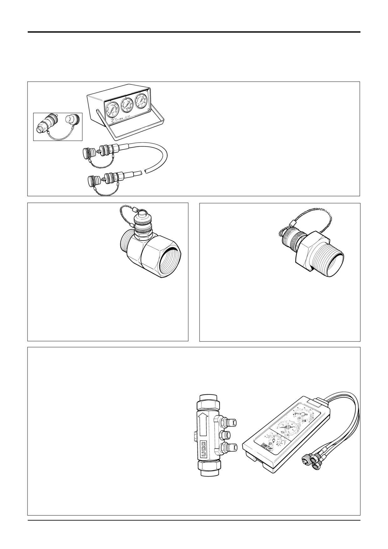
Hydraulic Circuit Pressure Test Kit
892/00253
Pressure Test Kit
:892/00201
Replacement Gauge 0-20 bar (0-300 lbf/in2)
:892/00202
Replacement Gauge 0-40 bar (0-600 lbf/in2)
:892/00203
Replacement Gauge 0-400 bar (0-6000 lbf/in2)
:892/00254
Replacement Hose
S267300
993/69800
Seal Kit for 892/00254 (can also be used with
probe 892/00706)
892/00706
Test Probe
S188121
S188131
Pressure Test Adapters
Pressure Test 'T' Adapters
892/00255
1/4 in BSP x Test Point
892/00256
3/8 in BSP x Test Point
S200141
892/00262
1/4 in M BSP x 1/4 in F BSP x Test Point
892/00257
1/2 in BSP x Test Point
816/55038
3/8 in M BSP x 3/8 in F BSP x Test Point
892/00258
5/8 in BSP x Test Point
816/55040
1/2 in M BSP x 1/2 in F BSP x Test Point
816/15118
3/4 in BSP x Test Point
892/00263
5/8 in M BSP x 5/8 in F BSP x Test Point
892/00259
1 in BSP x Test Point
892/00264
3/4 in M BSP x 3/4 in F BSP x Test Point
892/00260
1.1/4 in BSP x Test Point
892/00265
1 in M BSP x 1 in F BSP x Test Point
892/00261
5/8 in UNF x Test Point
Flow Test Equipment
892/00268
Flow Monitoring Unit
892/00269
Sensor Head 0 - 100 l/min (0 - 22 UK gal/min)
892/00293
Connector Pipe
892/00270
Load Valve
1406/0021
Bonded Washer
1604/0006
Adapter 3/4 in M x 3/4 in M BSP
1612/0006
Adapter 3/4 in F x 3/4 in M BSP
892/00271
Adapter 3/4 in F x 5/8 in M BSP
892/00272
Adapter 5/8 in F x 3/4 in M BSP
816/20008
Adapter 3/4 in F x 1/2 in M BSP
892/00275
Adapter 1/2 in F x 3/4 in M BSP
892/00276
Adapter 3/4 in F x 3/8 in M BSP
892/00277
Adapter 3/8 in F x 3/4 in M BSP
892/00273
Sensor Head 0 - 380 l/min
892/00294
Connector Pipe
1606/0015
Adapter 1.1/4 in M BSP x 1 in M BSP
892/00078
Connector 1 in F x 1 in F BSP
1604/0008
Adapter 1 in M x 1 in M BSP
1606/0012
Adapter 1 in M x 3/4 in M BSP
S188151
816/20013
Adapter 3/4 in F x 1 in M BSP
9803/3280
Issue 1
Section E
Hydraulics
Section E
1 - 2
Service Tools
1 - 2
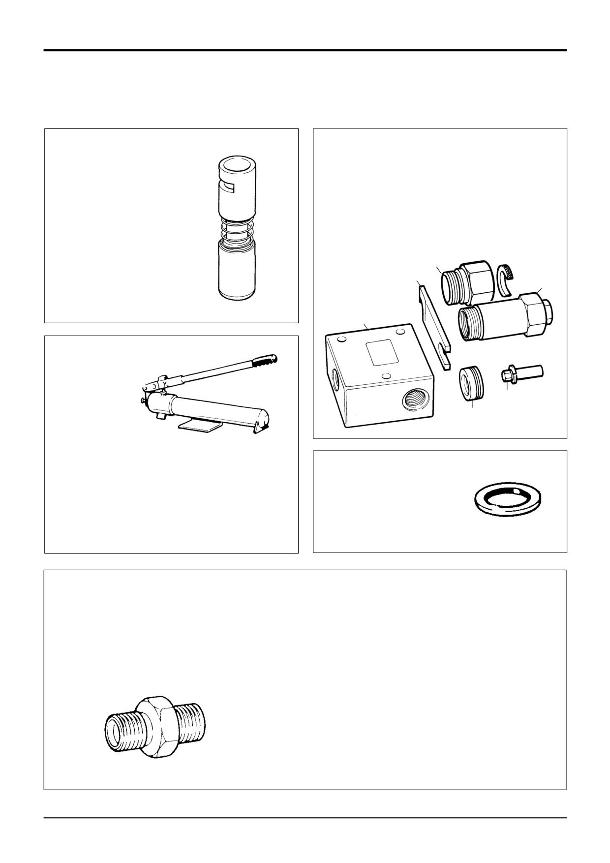
Components for Valve Block A.R.V. Testing
For 4CX Variable Flow machines use 25/201103
892/00881
Valve Spool
892/00309
A.R.V. Pressure Test Kit
Seal Fitting Tool
1
: 892/00340
Test Block Body
2
: 892/00341
Setting Body
3
: 993/68300
Adjusting Pin
4
: 892/00343
Spanner
5
: 892/00345
Anti-cavitation Lock Out Bung
6
892/00335
A.R.V. Cartridge Removal Tool
6
4
2
S261220
1
3
5
S196700
Hand Pump Equipment
892/00223
Hand Pump
Bonded Washers
892/00137
Micro-bore Hose 1/4 in BSP x 3 metres
892/00274
Adapter 1/4 in M BSP x 3/8 in M BSP Taper
1406/0011
1/4 in. BSP
892/00262
1/4 in M BSP x 1/4 in F BSP x Test Point
1406/0018
1/2 in. BSP
892/00706
Test Probe
1406/0014
5/8 in. BSP
892/00278
Gauge 0 - 40 bar (0 - 600 lbf/in2)
1406/0021
3/4 in. BSP
892/00279
Gauge 0 - 400 bar (0 - 6000 lbf/in2)
1406/0029
1.1/4 in. BSP
S188140
S193850
Male Adapters - BSP x NPT (USA only)
Male Adapters - BSP x BSP
816/00439
3/8 in. x 1/4 in.
1606/0003
3/8 in. x 1/4 in.
816/00440
1/2 in. x 1/4 in.
1604/0003
3/8 in. x 3/8 in.
816/15007
3/8 in. x 3/8 in.
892/00071
3/8 in. x 3/8 in. taper
816/15008
1/2 in. x 3/8 in.
1606/0004
1/2 in. x 1/4 in.
1606/0007
1/2 in. x 3/8 in.
1604/0004
1/2 in. x 1/2 in.
1606/0017
5/8 in. x 1/2 in.
1606/0008
3/4 in. x 3/8 in.
1606/0009
3/4 in. x 1/2 in.
1604/0006
3/4 in. x 3/4 in.
1606/0012
3/4 in. x 1 in.
1606/0014
3/4 in. x 1.1/4 in.
1606/0015
1 in. x 1.1/4 in.
S193860
9803/3280
Issue 1
Section E
Hydraulics
Section E
1 - 3
Service Tools
1 - 3
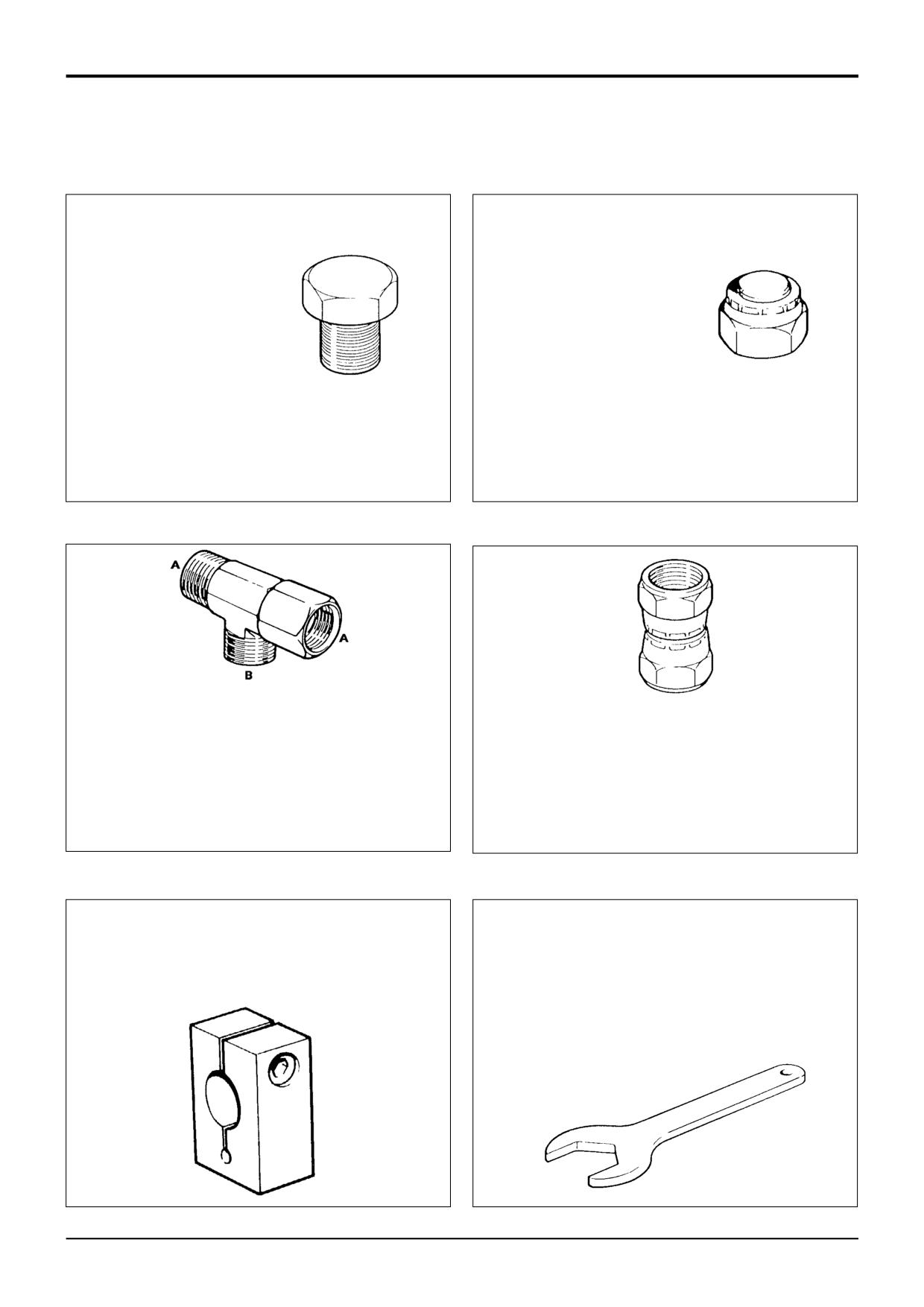
Female Cone Blanking Plug
892/00055
1/4 in. BSP
Male Cone Blanking Cap
892/00056
3/8 in. BSP
816/00294
1/4 in. BSP
892/00057
1/2 in. BSP
816/00189
3/8 in. BSP
892/00058
5/8 in. BSP
816/00190
1/2 in. BSP
892/00059
3/4 in. BSP
816/00197
5/8 in. BSP
892/00060
1 in. BSP
816/00196
3/4 in. BSP
816/00193
1 in. BSP
S193880
S193870
S193890
S193900
892/00047
3/8 in. BSP (A) x 1/4 in. BSP (B)
892/00048
1/2 in. BSP (A) x 1/4 in. BSP (B)
892/00049
5/8 in. BSP (A) x 1/4 in. BSP (B)
Female Connectors
816/50043
3/4 in. BSP (A) x 1/4 in. BSP (B)
892/00051
1 in. BSP (A) x 1/4 in. BSP (B)
892/00074
3/8 in. BSP x 3/8 in. BSP
816/50005
1/2 in. BSP (A) x 1/2 in. BSP (B)
892/00075
1/2 in. BSP x 1/2 in. BSP
816/60096
3/4 in. BSP (A) x 3/4 in. BSP (B)
892/00076
5/8 in. BSP x 5/8 in. BSP
816/00017
1 in. BSP (A) x 1 in. BSP (B)
892/00077
3/4 in. BSP x 3/4 in. BSP
992/09100
Excavator Spool Clamp
Hexagon Spanners for Ram Pistons and End Caps
892/00011
Spool Clamp
992/09300
55mm A/F
992/09400
65mm A/F
992/09500
75mm A/F
992/09600
85mm A/F
992/09700
95mm A/F
992/09900
115mm A/F
992/10000
125mm A/F
S216210
9803/3280
Issue 1
Section E
Hydraulics
Section E
1 - 4
Service Tools
1 - 4
7mm
11o
10mm
20mm
5mm
110mm
175mm
3o
892/01027
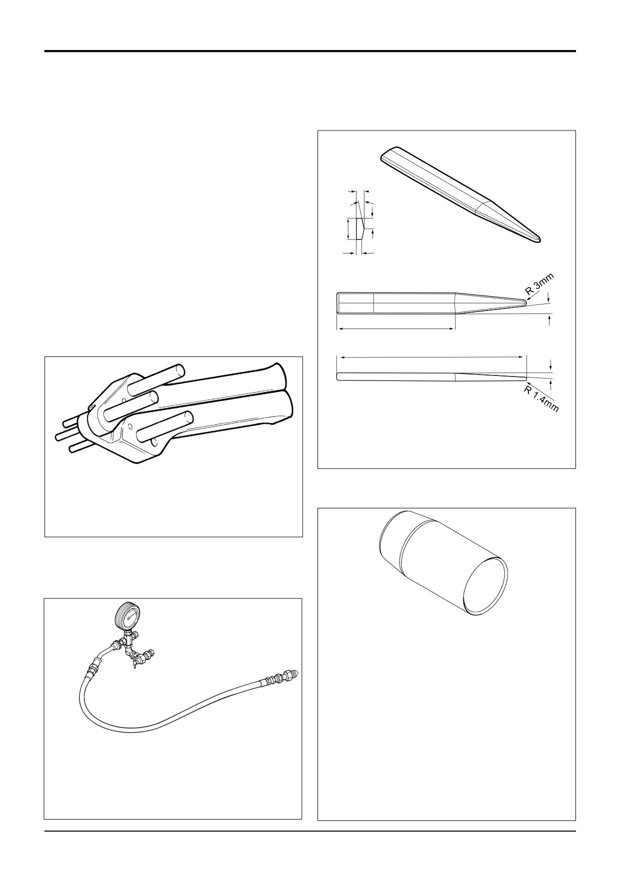
Piston Seal Assembly Tool
338500
S216250
892/00334
Ram Seal Fitting Tool
S338410
Ram Seal Protection Sleeves
892/01016
For 25 mm Rod Diameter
892/01017
For 30 mm Rod Diameter
892/01018
For 40 mm Rod Diameter
892/01019
For 50 mm Rod Diameter
892/01020
For 50 mm Rod Diameter (slew ram)
892/01021
For 60 mm Rod Diameter
892/01022
For 60 mm Rod Diameter (slew ram)
892/01023
For 65 mm Rod Diameter
S308271
892/01024
For 70 mm Rod Diameter
892/01025
For 75 mm Rod Diameter
892/00948
Charging Kit (without gauge)
892/01026
For 80 mm Rod Diameter
892/00949
Gauge
892/00167
For 90 mm Rod Diameter
9803/3280
Issue 1
Section E
Section E
Hydraulics
2 - 1
Technical Data
2 - 1
Hydraulic Pumps
Fixed Flow
Model/Reference
Double pump/4070H
Mounting
Gearbox
*
Theoretical displacement:
cc/rev
cu in/rev
Pump section 1 (mounting flange end)
33
2.01
Pump section 2
23
1.40
Flow at 2200 rev/min and system pressure (90% min displacement):
litres/min
UK gal/min
US gal/min
Pump section 1 (mounting flange end)
65.3
14.4
17.2
Pump section 2
45.5
10.0
12.0
Maximum speed @ pressure P1
3000 rev/min
Minimum speed @ pressure P1
500 rev/min
Approximate Weight
24kg (53 lbs)
Model/Reference
Double pump/83103
Mounting
Gearbox
*
Theoretical displacement:
cc/rev
cu in/rev
Pump section 1 (mounting flange end)
36
2.19
Pump section 2
26
1.59
Flow at 2200 rev/min and system pressure (90% min displacement):
litres/min
UK gal/min
US gal/min
Pump section 1 (mounting flange end)
71.3
15.7
18.8
Pump section 2
51.5
11.3
13.5
Maximum speed @ pressure P1
3000 rev/min
Minimum speed @ pressure P1
500 rev/min
Approximate Weight
23.8kg (52 lbs)
Model/Reference
Double pump/7441N
*
Mounting
Gearbox
Theoretical displacement:
cc/rev
cu in/rev
Pump section 1 (mounting flange end)
41
2.50
Pump section 2
26
1.59
Flow at 2200 rev/min and system pressure (90% min displacement):
litres/min
UK gal/min
US gal/min
Pump section 1 (mounting flange end)
81.2
17.9
21.5
Pump section 2
51.5
11.3
13.5
Maximum speed @ pressure P1
3000 rev/min
Minimum speed @ pressure P1
500 rev/min
Approximate Weight
24.5kg (54 lbs)
Model/Reference
Double pump/4071F
Mounting
Gearbox
*
Theoretical displacement:
cc/rev
cu in/rev
Pump section 1 (mounting flange end)
41
2.50
Pump section 2
29
1.77
Flow at 2200 rev/min and system pressure (90% min displacement):
litres/min
UK gal/min
US gal/min
Pump section 1 (mounting flange end)
81.2
17.9
21.5
Pump section 2
57.4
12.6
15.1
Maximum speed @ pressure P1
3000 rev/min
Minimum speed @ pressure P1
500 rev/min
Approximate Weight
24.5kg (54 lbs)
continued
9803/3280
Issue 2*
Section E
Section E
Hydraulics
2 - 2
Technical Data
2 - 2
Hydraulic Pumps
Fixed Flow (continued)
*
Model/Reference
Double pump/PGP620/Common outlet
Mounting
Gearbox
Theoretical displacement:
cc/rev
cu in/rev
Pump section 1 (mounting flange end)
29
1.77
Pump section 2
23
1.40
Flow at 2200 rev/min and system pressure (90% min displacement): litres/min
UK gal/min
US gal/min
Pump section 1 (mounting flange end)
57.4
12.6
15.1
Pump section 2
45.5
10.0
12.0
Maximum speed @ pressure P1
3000 rev/min
Minimum speed @ pressure P1
500 rev/min
Approximate Weight
24kg (53 lbs)
9803/3280
Issue 2*
Section E
Section E
Hydraulics
2 - 3
Technical Data
2 - 3
Hydraulic Pumps
Variable Flow
Type
Variable Displacement
Reference
A10VO - 978753
*
Mounting
Gearbox
Load Sense Pressure (in neutral position)
Maximum permitted - 5 bar; 72.5 lbf/in2
Load sense pressure relief Valve (if fitted)
230 bar; 3335 lbf/in2
Stand-by Pressure
20 bar; 290 lbf/in2
Maximum Hydraulic Stall Pressure
460001 to 472554 without relief valve
232 bar; 3364 lbf/in2
460001 to 472554 with relief valve and all from 472555
270 bar; 3915 lbf/in2
Maximum Displacement
74cc/rev; 4.5 in3/rev
Flow at 2200 rev/min and 2500 lb/in2 pressure †
- minimumum acceptable flow rate (new or rebuilt pump)
75 -80 litres/min; 16.5 - 17.6 UK gal/min
- minimumum acceptable flow rate (used pump)
70 - 75 litres/min; 15.4 - 16.5 UK gal/min
Flow in the Load Sense Line at 2200 rev/min (no pressure)
1 - 5 litres/min; 0.22 - 1.1 UK gal/min
Weight
TBAkg (TBA lbs)
† Note: It is not possible to test full pump flow at system pressure, figures quoted give a ‘snapshot’ indication of pump
performance. For more detail refer to Service Procedures, Variable Flow Pumps - Flow and Pressure Testing.
9803/3280
Issue 2*
Section E
Section E
Hydraulics
2 - 4
Technical Data
2 - 4
Relief Valve Pressures
Loader Valve - Fixed Flow
bar
kgf/cm2
lbf/in2
Main Relief Valve (M.R.V.)
236 - 241
240 - 245
3420 - 3500
Unloader Valve
207 - 214
207 - 211
3000 - 3100
Auxiliary Relief Valves (A.R.V.)
Loader
Shovel Ram Head Side
172 - 179
176 - 183
2500 - 2600
Shovel Ram Rod side
310 - 317
316 - 323
4500 - 4600
Note: Instructions for pressure testing and adjustment are described in Service Procedures, Loader Valve - Pressure
Testing.
Weight
25kg (55lbs) (3 spool)
TBA (2 spool)
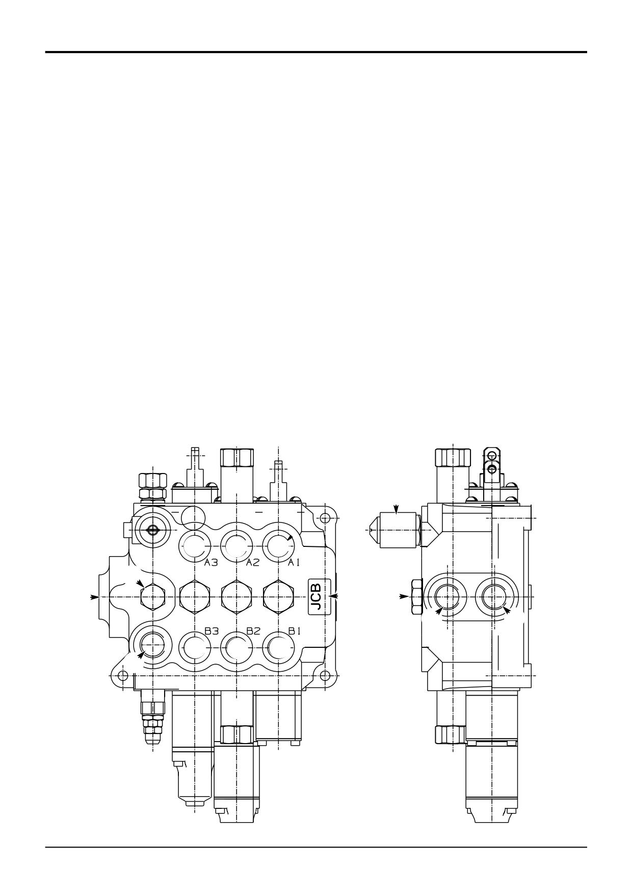
Component Key:
1
Arms lift service
8
Unloader solenoid
2
Shovel service
9
Auxiliary relief valve
3
Auxiliary (optional)
10
Tank port
4
Pump section 1 - inlet
11
High pressure carry-over (HPCO) port
5
Pump section 2 - inlet
12
Service ports
6
Pressure test port
13
Load hold check valve assemblies
7
Unloader Assembly
14
Data plate
1
2 3
7
9
8
@
@
@
6
5
$
£
0
!
@
@
@
4
9
A262160
9803/3280
Issue 1
Section E
Section E
Hydraulics
2 - 5
Technical Data
2 - 5
Relief Valve Pressures
Loader Valve - Precision Control (Servo)
*
(Machines up to serial no. 931159)
bar
kgf/cm2
lbf/in2
Main Relief Valve (M.R.V.)
227 - 231
232 - 235
3300 - 3350
Unloader Valve
203 - 207
207 - 211
2950 - 3000
Auxiliary Relief Valves (A.R.V.)
Loader
Shovel Ram Head Side
172 - 175
175 - 179
2500 - 2550
Shovel Ram Rod side
308 - 312
315 - 318
4475 - 4525
Bolt on Auxiliary Spool (extending dipper, if fitted)
Top relief valve
136 - 140
139 - 142
1975 - 2025
Bottom relief valve
205 - 208
209 - 212
2975 - 3025
Note: Instructions for pressure testing and adjustment are described in Service Procedures, Loader Valve - Pressure
Testing.
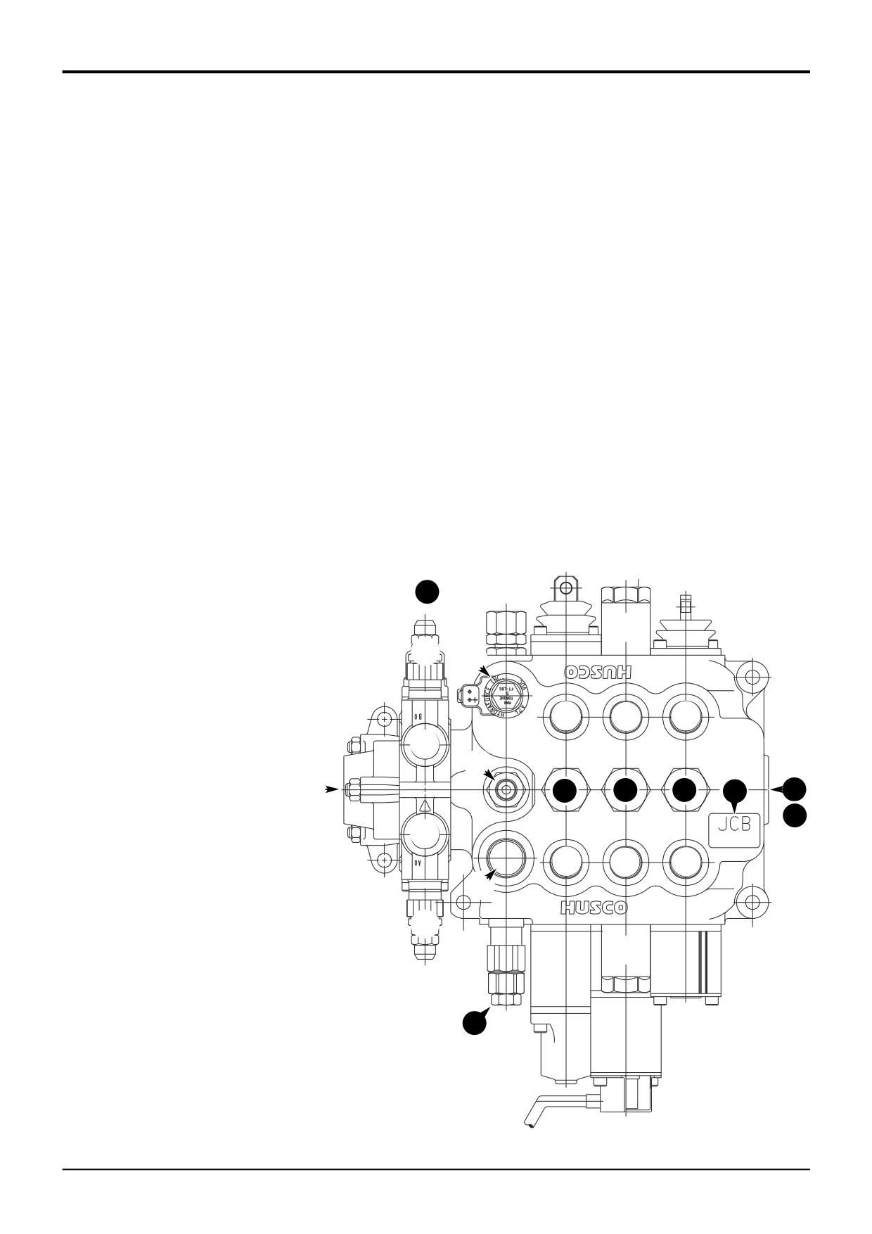
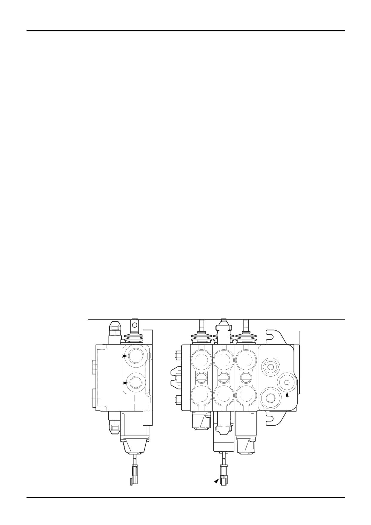
Component Key:
1
Arms lift service
2
Shovel service
3
Auxiliary (optional)
4
Pump section 1 - inlet
1
2
3
5
Pump section 2 - inlet
6
Pressure test port
15
7
7
Unloader Assembly
8
Unloader solenoid
9
9
Auxiliary relief valve
10
Tank port
9
8
11
High pressure carry-over (HPCO) port
12
Service ports
13
Load hold check valve assemblies
14
Main relief valve (MRV)
@
@
@
15
Bolt on auxiliary spool
16
Data plate
@
6
13
13
13
16
10
5
11
@
@
@
@
4
9
9
14
A402480
9803/3280
Issue 3*
Section E
Section E
Hydraulics
2 - 5A
Technical Data
2 - 5A
Relief Valve Pressures
Loader Valve - Precision Control (Servo)
(Machines from January 2003)
bar
kgf/cm2
lbf/in2
Auxiliary Relief Valves (A.R.V.)
Shovel Ram Head Side
310
315
4500
Shovel Ram Rod Side
170
175
2500
Note: Instructions for pressure testing and adjustment are described in Service Procedures, Loader Valve - Pressure
Testing.
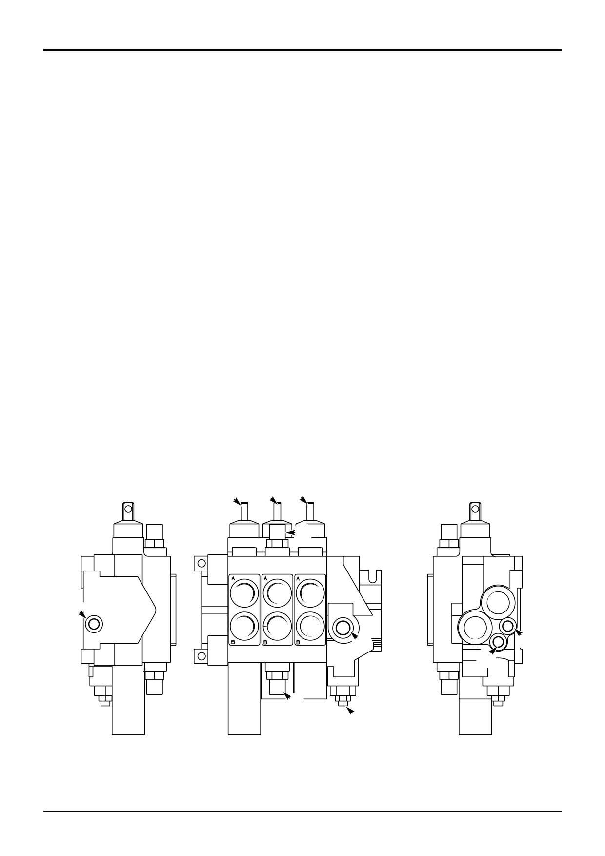
Component Key:
1
Auxiliary (options)
2
Shovel service
3
Arms lift service
4
Auxiliary relief valves
5
Electric detent spool connector
6
Inlet port (secondary pump section P2)
7
Tank port
8
Inlet port (main pump section P1)
9
Service ports
1 2 3
4
A
A
A
7
9
9
9
T
LS
8
P
P
9
9
9
T
6
B
B
B
4
5
A403690
9803/3280
Issue 1
Section E
Section E
Hydraulics
2 - 7
Technical Data
2 - 7
Relief Valve Pressures
Loader Valve - Variable Flow
bar
kgf/cm2
lbf/in2
Priority Relief Valve†
170 - 176
173 - 179
2450 - 2550
Auxiliary Relief Valves (A.R.V.) @ 0.5gal/min (1.9 litres/min)
Shovel Ram Head Side
170 - 174
173 - 177
2465 - 2520
Shovel Ram Rod side
306 - 314
312 - 320
4450 - 4550
† Note: Steer circuit pressure is controlled by a relief valve housed in the hydraulic steer unit (Refer to Section H Steering).
The priority relief valve housed in the loader valve must be set at 2500 lb/in2, this will ensure it does not interfere with the
operation of the relief valve housed in the hydraulic steer unit.
Weight:
2 Spool - TBA kg (TBA lbs)
3 Spool - TBA kg (TBA lbs)
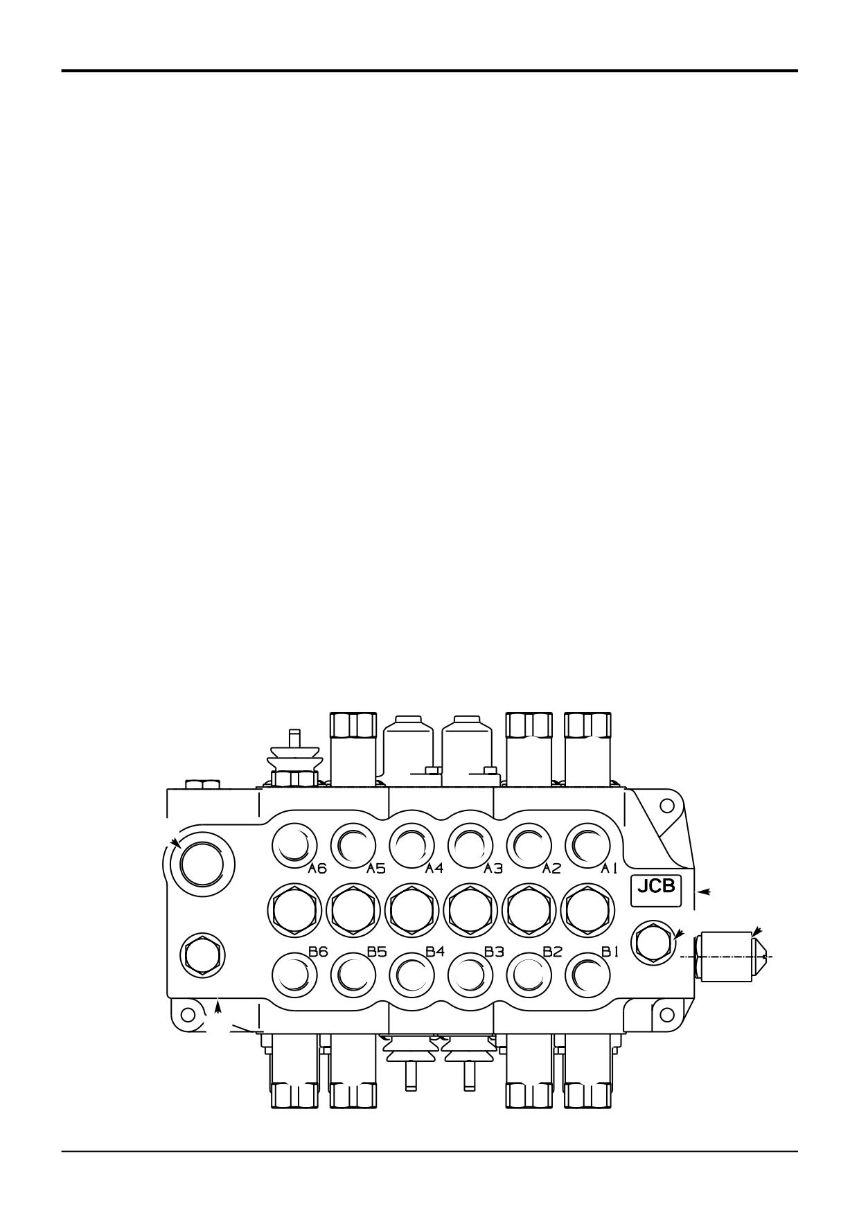
Component Key:
1
Auxiliary (optional) service
2
Shovel service
3
Arms lift service
4
Pump inlet
5
Tank port
6
Load sense port (to pump)
7
Priority load sense port (from steer unit)
8
Priority work port (to steer unit)
9
Load sense carry over port (to backhoe valve)
10
Service ports
11
Auxiliary relief valve (rod side)
12
Auxiliary relief valve (head side)
13
Priority relief valve †
3 21
!
0
0
0
4
9
0
0
0
5
6
8
7
@
£
A273670
9803/3280
Issue 2*
Section E
Section E
Hydraulics
2 - 8
Technical Data
2 - 8
Relief Valve Pressures
Excavator Valve - Fixed Flow
bar
kgf/cm2
lbf/in2
Boom Ram Head Side
248 - 255
253 - 260
3600 - 3700
Boom Ram Rod Side
345 - 352
351 - 358
5000 - 5100
Bucket Ram Head Side
Centremount (17' , 15’ 6” backhoe - except knuckle)
310 - 317
316 - 323
4500 - 4600
Centremount (14' backhoe, 15’ 6” backhoe with a knuckle fitted)
248 - 255
253 - 260
3600 - 3700
Sideshift
248 - 255
253 - 260
3600 - 3700
Bucket Ram Rod Side (Machines with Rockbreaker only)
248 - 255
253 - 260
3600 - 3700
Dipper Ram Head Side
248 - 255
253 - 260
3600 - 3700
Dipper Ram Rod Side
248 - 255
253 - 260
3600 - 3700
Slew Left and Right
262 - 269
267 - 274
3800 - 3900
Weight:
44 kg (97 lbs) - Centremount
46 kg (101 lbs) - Sideshift
Note: Instructions for pressure testing and adjustment are described in Service Procedures, Loader Valve - Pressure
Testing.
† System shown is for JCB plus pattern and JCB diagonal pattern. For ISO system, the boom and dipper spools change
position, i.e. boom is position 2 and dipper is position 5. The bottom ARV from spool 5 will also be swapped with the
bottom ARV from spool 2.
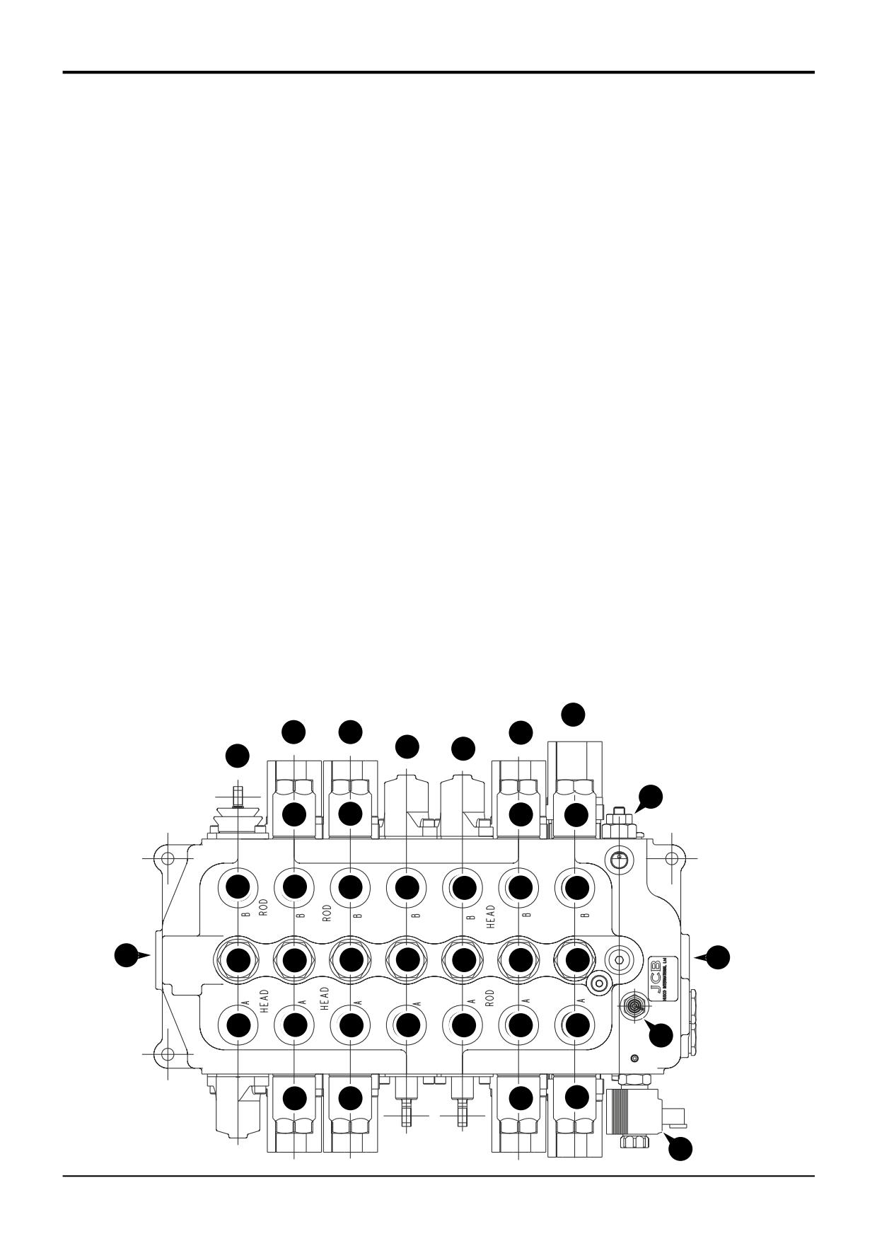
Component Key:
8
Tank port
1
Bucket crowd
9
High pressure carry-over (HPCO) port
2
Dipper †
10
Service ports
3
Stabiliser
11
Load hold check valve assemblies
4
Stabiliser
12
Make-up check valve assembly
5
Boom †
13
Inlet port
6
Slew
14
Hydraclamp solenoid
7
Auxiliary relief valve
1
2
3
4
5
6
7
7
7
8
0
0 0
0
0
0
£
!
!
!
!
!
!
@
$
0
0
0
0
0
0
9
7
7
7
7
A401470
9803/3280
Issue 2*
Section E
Section E
Hydraulics
2 - 10
Technical Data
2 - 10
Relief Valve Pressures
Excavator Valve - Precision Control (Servo)
*
(Machines up to serial no. 931159)
bar
kgf/cm2
lbf/in2
Boom Ram Head Side
248 - 255
253 - 260
3600 - 3700
Boom Ram Rod Side
345 - 352
351 - 358
5000 - 5100
Bucket Ram Head Side
248 - 255
253 - 260
3600 - 3700
Bucket Ram Rod Side
248 - 255
253 - 260
3600 - 3700
Dipper Ram Head Side
248 - 255
253 - 260
3600 - 3700
Dipper Ram Rod Side
248 - 255
253 - 260
3600 - 3700
Slew Left and Right
262 - 269
267 - 274
3800 - 3900
Load Sense Relief Valve †
208 - 212
213 - 216
3025 - 3075
Note: Instructions for pressure testing and adjustment are described in Service Procedures, Loader Valve - Pressure
Testing.
† Note: For pressure testing and adjustment of the load sense relief valve, see Service Procedures, Pressure Testing, Load
Sense Drain Regulator and Relief Valve.
Component Key:
9
Pilot operated check valve (hydraclamp)
1
Bucket
10
Service ports
2
Dipper
11
Load sense valve
3
Stabiliser
12
Load sense drain regulator and relief valve
4
Stabiliser
13
Inlet port
5
Boom
14
Hydraclamp solenoid
6
Slew
15
Auxiliary spool
7
Auxiliary relief valve
8
Tank port
6
1
2
5
3
4
15
12
7
7
7
7
10
10
10
10
10
10
10
8
13
11
11
11
11
11
11
11
10
10
10
10
10
10
10
9
7
7
7
7
14
A402500
9803/3280
Issue 3*
Section E
Section E
Hydraulics
2 - 10A
Technical Data
2 - 10A
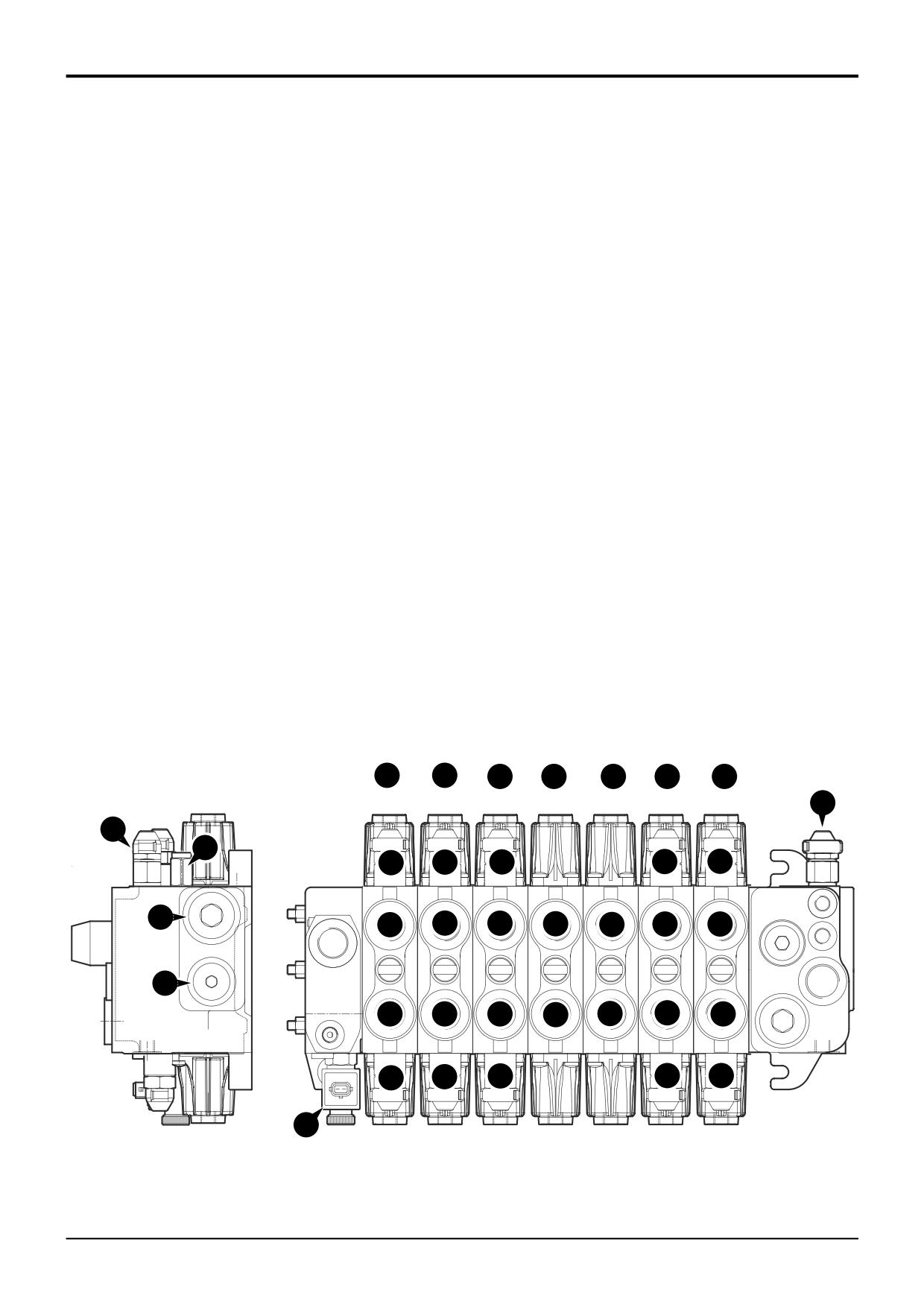
Relief Valve Pressures
Excavator Valve - Precision Control (Servo)
(Machines from January 2003)
bar
kgf/cm2
lbf/in2
Auxiliary Relief Valves (A.R.V.)
Boom Ram Head Side
245
250
3550
Boom Ram Rod Side
350
355
5000
Bucket Ram Head Side
255
260
3700
Bucket Ram Rod Side
255
260
3700
Dipper Ram Head Side
255
260
3700
Dipper Ram Rod Side
255
260
3700
Slew Left and Right
265
270
3850
Load Sense Relief Valve †
250
255
3650
Note: Instructions for pressure testing and adjustment are described in Service Procedures, Loader Valve - Pressure
Testing.
† Note: For pressure testing and adjustment of the load sense relief valve, see Service Procedures, Pressure Testing, Load
Sense Relief Valve.
Component Key:
1
Auxiliary (options)
9
Anti-cavitation valve
2
Bucket
10
Load sense relief valve
3
Dipper
11
Flow regulator valve
4
Stabiliser
12
Hydraclamp solenoid
5
Stabiliser
13
Inlet port
6
Boom
14
Tank port
7
Slew
15
Service ports
8
Auxiliary relief valves
1
2
3
4
5
6
7
10
10
11
9
8
8
8
8
A
A
A
A
A
A
A
14
T1
15
15
15
15
15
15
15
T
LS
T3
13
P
P
15
15
15
15
15
15
15
C
M
B
B
B
B
B
B
B
8
8
8
8
8
12
A403680
9803/3280
Issue 1