JCB 3CX, 4CX, 214e, 214, 215, 217 & VARIANTS Backhoe Loader. Service Manual - page 9
Section D
Controls
Section D
30 - 1
Steering Column
30 - 1
A
C
C
B
B
B
L
B
M
N
F
P
F
R
H
H
H
T
H
S
E
G
D
G
J
A396921
9803/3280
Issue 2*
Section D
Controls
Section D
30 - 2
Steering Column
30 - 2
Removal and Replacement
Dismantling and Assembly
The steering column can be tilted to improve operator reach
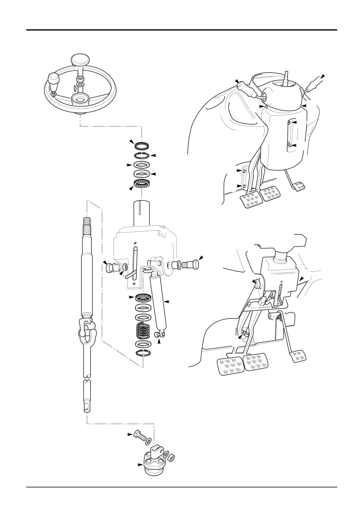
The illustration on the adjacent page is intended as a guide
and comfort levels. This type of assembly is refered to as a
to dismantling and assembly.
‘tilt column’.
Dismantling
The illustration on the adjacent page is intended as a guide
to removal and replacement.
1
Using a screwdriver in the slot, carefully prise out the
dust seal L from the outer column tube.
Removal
2
Remove external circlip M, washer N, tolerance ring P
*1
Park the machine on firm level ground, engage the
and withdraw the steering shaft from the outer column
parking brake and set the transmission to neutral.
tube and pivot bracket.
Lower the loader arms to the ground. Switch OFF the
engine, remove the starter key and disconnect the
Note: The top and bottom bearings R and S housed in the
battery.
outer column tube are non serviceable parts. They may be
removed for cleaning and inspection, but if the bearing(s)
2
Remove the steering wheel as shown at A.
have failed a new outer column tube and pivot bracket
assembly must be used.
3
Remove socket screws B and take off the steering
column pedestal cover.
Note: The gas damper strut E is a non serviceable part. If
the damper is faulty it must be replaced with a new one.
4
Remove the control column switches C.
Assembly
5
Remove the socket screw D securing the gas damper
*
strut E.
Assembly is the reverse of the dismantling sequence.
6
Remove socket screws F and lift up the rubber
protective cover behind the brake pedals to gain
access to the flexible coupling.
7
Remove the coupling bolt G and shoulder bolts H.
*
Then carefully withdraw the steering column assembly
(with the gas damper strut attached) from the flexible
coupling J.
Replacement
Replacement is the reverse of the removal sequence.
Apply JCB Threadlocker and Sealer to threads of nuts T.
*
Note: The coupling bolt G must engage with the cut-out in
the shaft.
After re-fitting check that the steering tilt functions correctly,
*
and that the direction indicators and lights operate correctly.
Check that the wires from the brake pedal switch do not rub
on the steering column.
*
Torque Settings
Item
Nm
kgf m lbf ft
D
14
1.4
10.3
H
40
4.1
29.5
9803/3280
Issue 2*
Section D
Controls
Section D
31 - 1
Shovel Reset
31 - 1
H
B
F
C
E
G
A
H
2065mm
J
M
K
L
A320510
9803/3280
Issue 1
Section D
Controls
Section D
31 - 2
Shovel Reset
31 - 2
214e Machines Only
Fitting
1
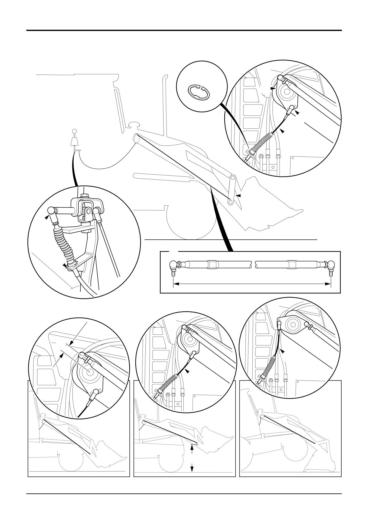
Adjust the feedback link A to 2065mm (81.3in). After
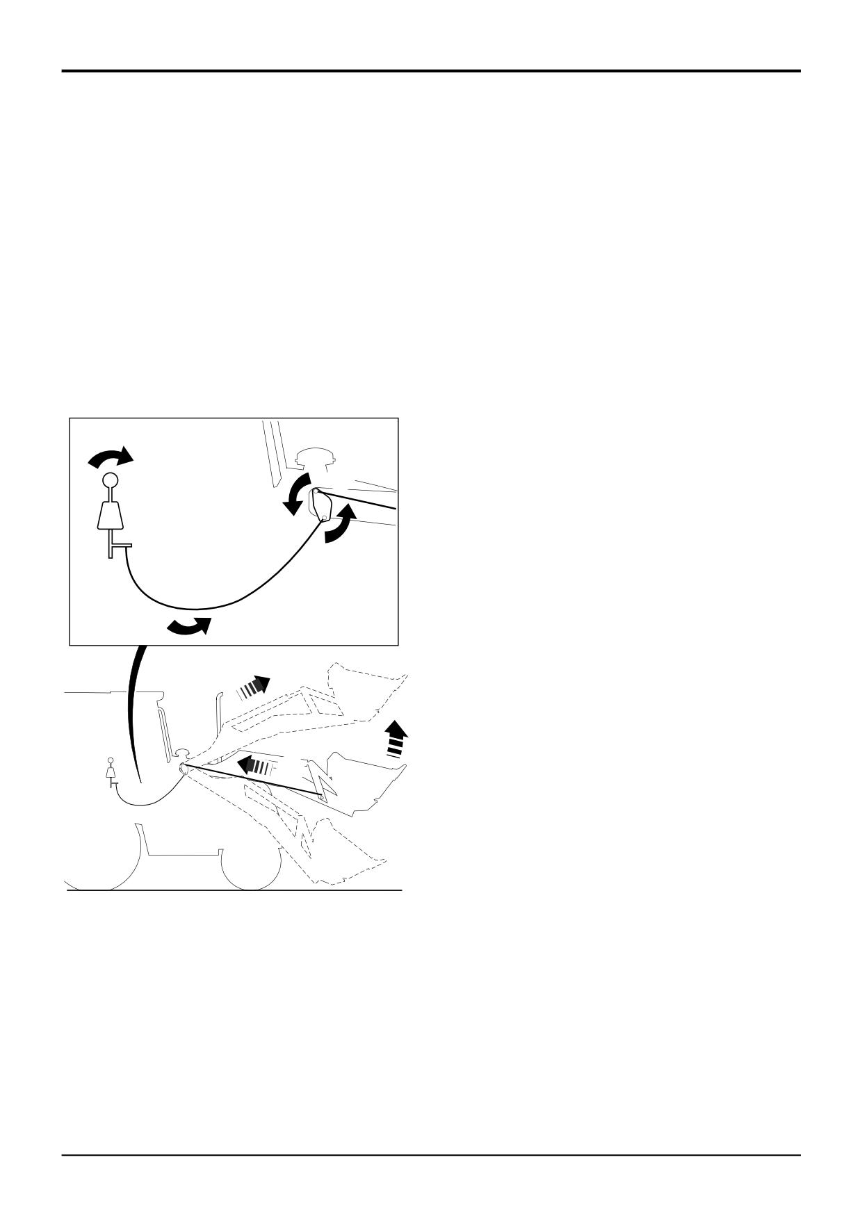
The shovel reset system is designed to automatically tilt the
adjusting tighten the lock nuts.
shovel forward when the loader arms are raised, this
prevents a heaped shovel from depositing its contents over
2
Fit cam plate B with the single threaded hole at the top.
the back of the shovel onto the bonnet or cab when the
loader arms are raised.
3
Fit feed back link A to cam plate and shovel lever E.
When the loader arms are raised the feed back link A causes
4
Connect cable C to the bottom centre position F on the
the cam plate B to rotate anti-clockwise. The rotation of the
cam plate B, secure in position.
cam plate pulls the cable C which selects the loader valve
block shovel spool D to tip the shovel forwards.
Note: The factory fit position for the cable end ball joint to
cam plate is the centre position. Because of component
When either a cable or feedback link is changed or if the
variation it is permissible to fit the cable end ball joint in
shovel reset system is not operating correctly carry out
either the forward or rear position. The forward position will
functional adjustment check.
advance the levelling and the rear position will delay the
levelling.
5
Connect cable C to the loader arm control lever G.
6
Secure cable ends with spring clips H.
D
B
7
Carry out the adjustment procedure.
Adjustment
1
Roll the shovel fully back and lower to the ground.
2
The feedback link position in relation to the loader arm
pivot pin measurement J should be 40mm (1.5in).
Adjust feedback link as required.
C
3
When the loader arms are raised there should be no
slack in the cable at K when the shovel arm pivot pin L
is 1.0 to 1.5 meters (3.5 to 5.0 feet).
4
Roll the shovel fully forward and fully retract the lift
arms, this will raise the front wheels off the ground.
5
In this position there should be slack in the cable at M,
if not adjust the cable as required.
A
Note: Whenever any adjustment is made repeat steps 4/5 to
make sure there is slack in the cable with the shovel rolled
fully forward.
A320500
9803/3280
Issue 1
Section D
Controls
Section D
33 - 1
Return To Dig
33 - 1
X
2
1
A374040
9803/3280
Issue 1
Section D
Controls
Section D
33 - 2
Return To Dig
33 - 2
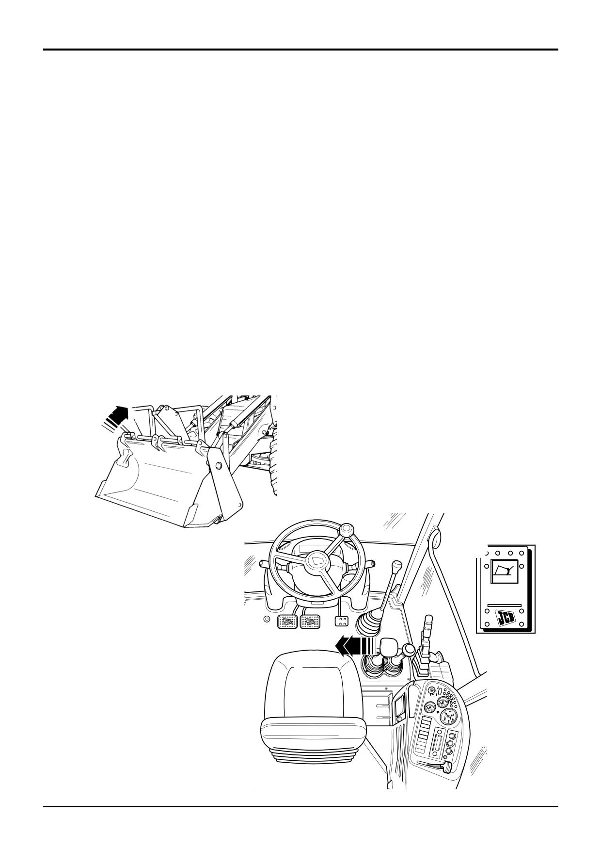
Operation
Adjustment
This enables you to roll the shovel from the rolled forward
1
Lower the loader arms and position the shovel in the
position into the digging position quickly and easily.
required ‘Return To Dig’ position.
When you select ‘Return To Dig’ a proximity switch on one
2
Switch OFF the engine but leave the ignition ON.
of the loader arms cuts off the hydraulic pressure to the
shovel rams immediately the shovel reaches the correct
3
Press the ‘Return To Dig Enable’ switch to ON.
angle for digging.
4
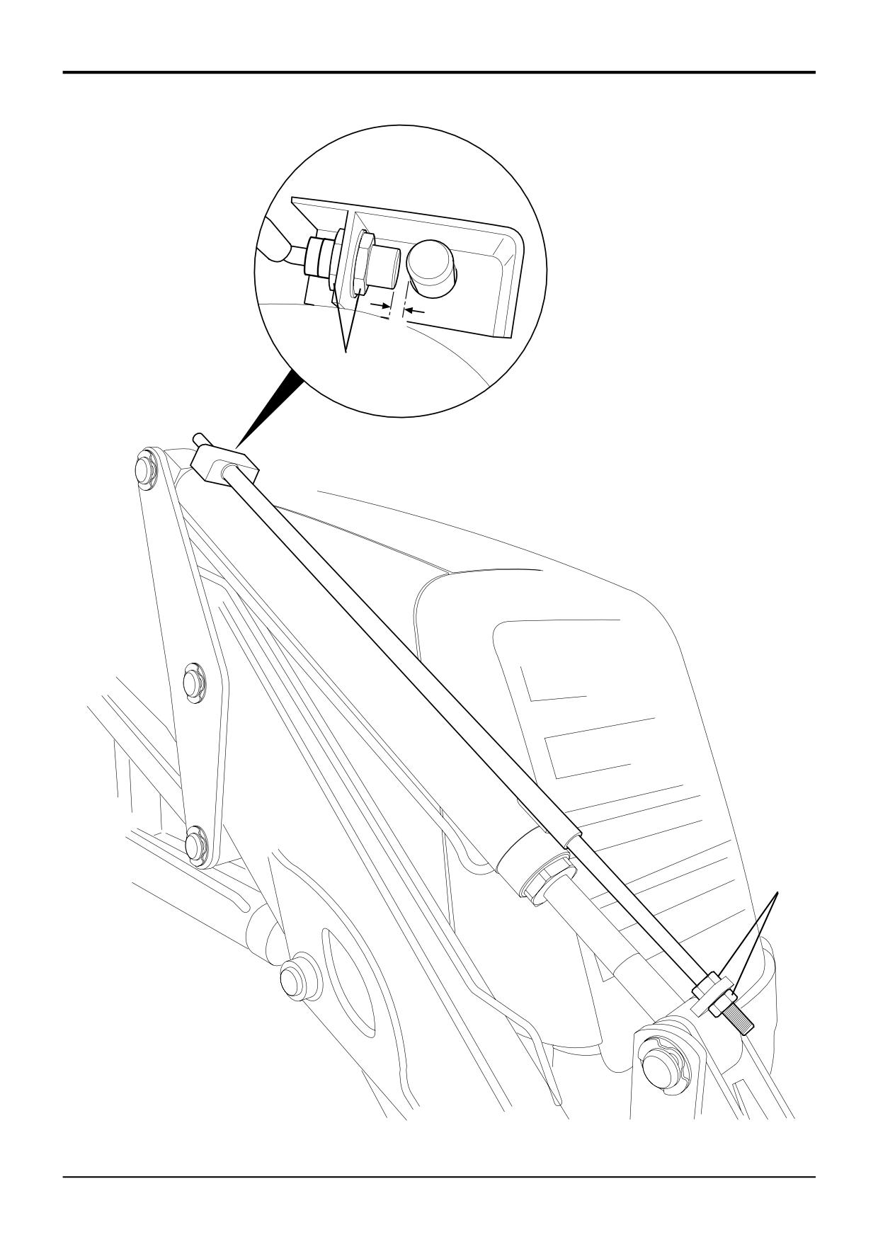
Adjust the rod with nuts 1 so that the LED on the
proximity switches illuminates/extinguishes at this
To select ‘Return To Dig’:
position.
1
Press the ‘Return To Dig Enable’ switch A to the ON
5
Adjust the proximity switch with nuts 2 to give a
position, the switch will illuminate.
clearance X of 2 mm (0.08 in).
2
Pull the loader lever to the left as far as it will go. You
will feel a slight pressure on the lever as it passes
through the Roll Back position.
Release the lever, it will stay in the detent position until
the shovel reaches the return to dig position when the
lever will automatically return to the central hold
position.
3
When return to dig is no longer required press the
enable switch to the OFF position.
A
A401050
9803/3280
Issue 1
Section D
Controls
Section D
35 - 1
Precision Control (Servo)
35 - 1
Basic System Operation
Component Location
B
S
C
A
L
J
S
H
P
U
N
U
P
V
K
D
R
Q
E
M
U
U
U
G
F
T
A402030
9803/3280
Issue 1
Section D
Controls
Section D
35 - 2
Precision Control (Servo)
35 - 2
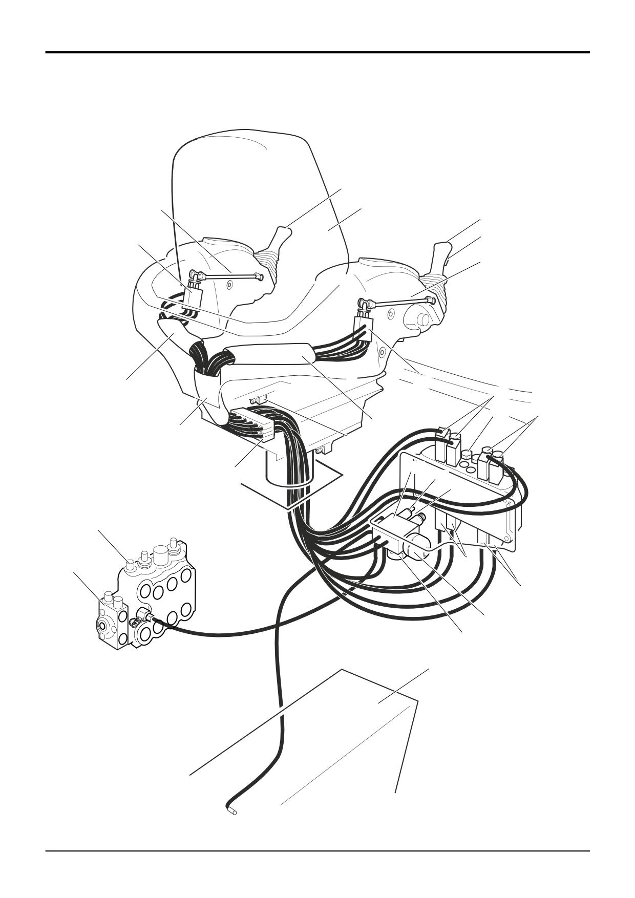
The following section describes the JCB Precision Control
*
Basic System Operation
system fitted to machines up to serial number 931159. There
is another JCB Precision Control system fitted to later
Component Identification
machines, which is described in a separate section. Refer to
Precision Control (Servo) - Machines from January 2003.
A
Right hand joystick
B
Left hand joystick
Circuit Description
C
Operator seat
D
Pilot supply valve
The JCB Precision Control system facilitates operation of the
E
Supply valve solenoid
backhoe (excavator) via joysticks A and B mounted in the
F
Oil filter access plug
arms of the operator’s seat. Unlike manual machines the
G
Accumulator
excavator valve spools are moved by hydraulic pressure and
H
Right hand pilot control valve
not directly by a mechanical levers.
J
Left hand pilot control valve
K
Seat mounted micro switch
A pilot supply valve D maintains a constant supply of oil at
L
Joystick mounted ‘mode switch’
servo pressure to the right and left hand pilot control valves
M
Loader valve block
H and J. The valves are mounted at the rear of the seat arm
N
Excavator valve block
rests.
P
Hose sleeves
Q
Pressure relief valve
The joysticks each operate a hydraulic pilot control valve (H
R
Hose clamps (seat base mounted)
or J as applicable) via a mechanical linkage. These valves in
S
Mechanical linkages
turn operate the excavator valve spools via hydraulic pilot
T
Machine hydraulic tank
pressure. The interconnecting hoses are routed to and from
U
Bolt on spool section - extending dipper (if fitted)
the pilot control valves through the central seat support pillar
V
Plastic cover panel
and then through the cab floor.
The mechanical linkages S incorporate universal type
couplings at both ends.
The joysticks control boom, dipper, bucket and slew
functions. Unlike manual control machines, the foot pedal
controlled auxilary valve spool (typically used to operate the
extending dipper ram) is located on the loader valve block.
For details of this valve spool see Section E.
The seat arms incorporating the joysticks are adjustable for
both height and length. A gas strut mounted in the left hand
arm supports the weight of the assembly when adjusting the
height.
Note: Precision control machines - extending dipper.
When fitted, the extending dipper ram is controlled by bolt
on spool section U located on the loader valve. The spool is
actuated by the normal foot pedal via a cable.
E
Q
D
A402080
F
9803/3280
Issue 2*
Section D
Controls
Section D
35 - 3
Precision Control (Servo)
35 - 3
M
R
D
L
S
TL
K
Q
E
T
G
E
SAE +
F
D
Q
TR
TL
T
J
B
F
TP
T
3
PL
3J
PL
P
P
4
2
TR TL PR
P
4J
2J
PR
1
1J
TP
G
S1a
S1b
S2b
S2a
S3a
H
S3b
T
A
S4a
S4b
2H
P
2
3
1
3
3H
1H
P
N
4
4
4H
T
2
H
1
Z
ISO +
J
SAE +
T
T
S3a
4J
2J
S3b
P
4
3
Key to Oil Flow & Pressure
3
2
1
P
T
4
S2a
3H
1H
S2b
Full Pressure
1
Servo
Exhaust
2
A402070
9803/3280
Issue 1
Section D
Controls
Section D
35 - 4
Precision Control (Servo)
35 - 4
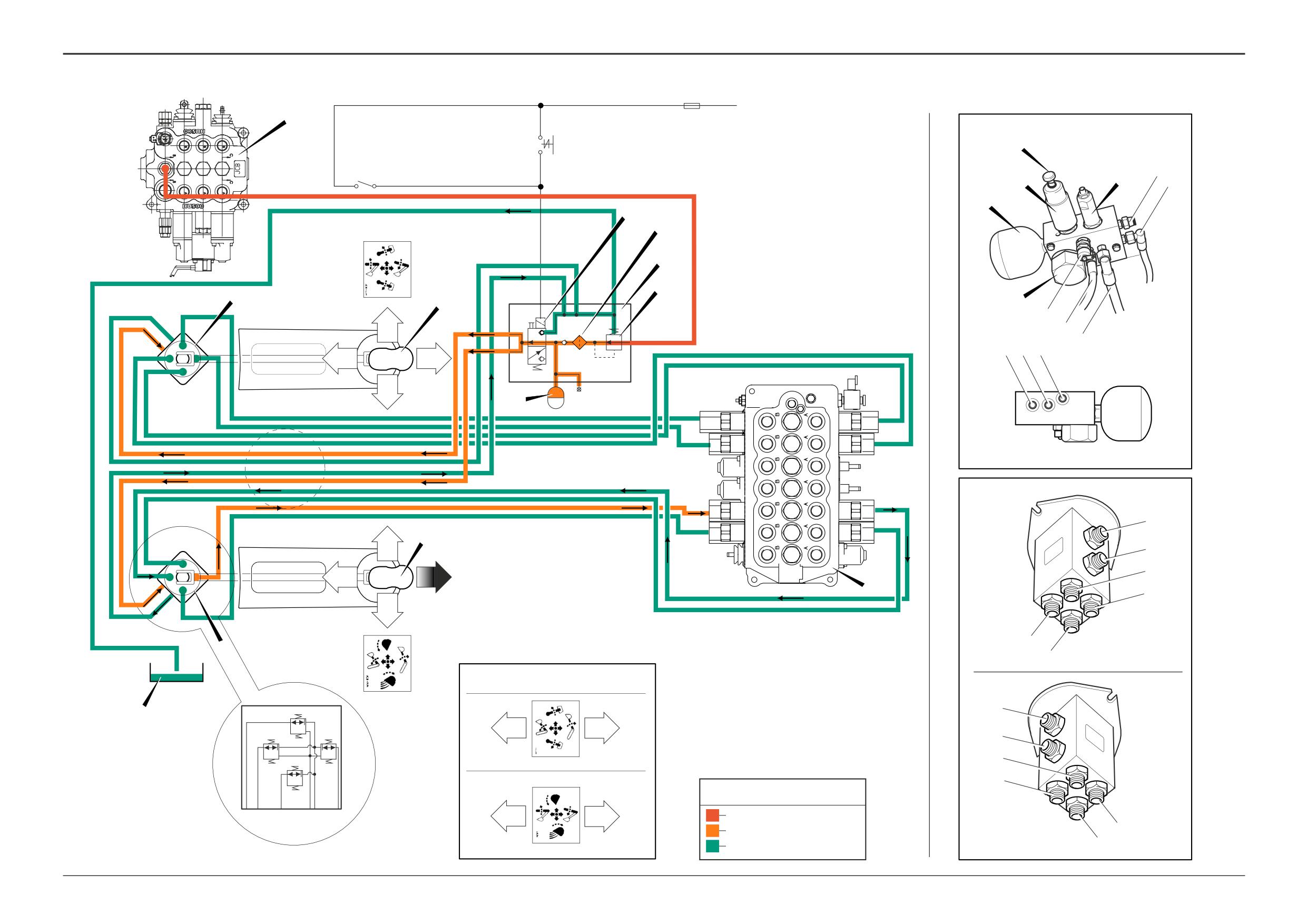
Basic System Operation
Hydraulic Operation
Component Key:
A
Right hand joystick
B
Left hand joystick
Oil at system pressure flows to the pilot supply valve D via a
D
Pilot supply valve
hose connected at the loader valve M. An integral pressure
E
Supply valve solenoid
relief valve Q maintains the oil at ‘pilot’ pressure.
F
Oil filter
When the operator actuates the system by revolving the
G
Accumulator
seat to face the rear, or by operating the mode switch,
H
Right hand pilot control valve
solenoid E is energised and moves the pilot supply valve
J
Left hand pilot control valve
spool. Oil flows to the pilot control valves H and J.
K
Seat mounted micro switch
L
Joystick mounted ‘mode switch’
Each pilot control valve contains four spool valve ‘capsules’,
M
Loader valve block
numbered 1 to 4 on each valve. The valves are operated by
N
Excavator valve block
moving the associated joystick. With the joystick in the
P
Machine hydraulic tank
neutral position all the valves vent oil from the excavator
Q
Pressure relief valve
valve pilot ports S1-S4 to tank.
R
Fuse
S
Solenoid manual override control knob
Example Operation:
S1a
Excavator Pilot port - Slew ram spool
When the operator moves the right hand joystick forward
S1b
Excavator Pilot port - Slew ram spool
the mechanical linkage connected to pilot valve H pushes
S2a
Excavator Pilot port - Boom ram spool
spool 1 down. Oil at pilot pressure is diverted to port S3b.
S2b
Excavator Pilot port - Boom ram spool
in the excavator valve N. This causes the dipper spool to
S3a
Excavator Pilot port - Dipper ram spool
move and operate the dipper ram. As the dipper spool
S3b
Excavator Pilot port - Dipper ram spool
moves, oil is vented from port S3a via spool 3 and port T in
S4a
Excavator Pilot port - Bucket ram spool
control valve H.
S4b
Excavator Pilot port - Bucket ram spool
T
Tank
The valve ‘capsules’ feature proportional control. This
enables backhoe precision control. Each valve capsule
Note that the diagram opposite shows the servo hoses
modulates oil pressure supplied to the associated excavator
connected to give the SAE + (JCB +) control pattern. For
valve pilot line in proportion to the joystick position. The
ISO + control pattern some servo hoses are connected
further the joystick is moved the greater the pilot pressure
differently at the excavator valve, as shown at Z.
and the further the associated excavator valve spool moves.
Accumulator G maintains hydraulic pressure for several
Electrical Operation
operations of the excavator spools with the engine stopped.
This allows venting of pressure from the backhoe hydraulic
A solenoid actuated valve is incorporated in the pilot supply
rams, or lowering of a load in the event of engine failure.
valve block D. The solenoid is controlled either by micro
switch K or ‘mode switch’ L.
When the operator seat is revolved to face the rear of the
machine switch K is closed. This energises solenoid E and
oil at pilot pressure is diverted to the 2 pilot control valves H
and J, thus enabling the system. Solenoid E also
incorporates a manual override facility (S). This enables the
backhoe to be operated in an emergency situation, in the
event of solenoid or electrical failure for example.
In some circumstances the operator may require actuation
of the backhoe with the seat in the forward position (when
un-sticking from boggy ground for example). This is
achieved by means of joystick mounted mode switch L. The
switch energises solenoid E and the system is enabled.
The left hand joystick houses a horn switch. On some
machines the joysticks also incorporate switches for control
of a hydraulic quickhitch and changeover from auxilary
(typically jaw bucket) to extending dipper operation.
9803/3280
Issue 1
Section D
Controls
Section D
36 - 1
Precision Control (Servo)
36 - 1
Electrical Connections
1
HH
3
HA
600GT
1
1
1
4
4
1
3a
921
2
2
6
4
5
5
4
930
3
2
3
3
2
3
3b
3
6
6
3
931
4
4
HB HD
SD
2
7
7
2
101BG
2
1
8
8
1
A1
CTG
HB
SH
101AG
101Y
2
2
101Y
CP
4
5
5
4
875
5
5
875
3
7
7
5
875B
600KH
3
6
6
3
600KH
4
7
TA
2
7
7
2
1
8
8
1
SC
DR2
1
2
CTB
HD
1
2
1
2
CM
1
2
921
5
5
921
5
4
5
5
4
SA
8
929
7
7
929
101BJ
1
2
1805C
1805F
1
2
600HX
1
2
1
2
931
8
3
6
6
3
8
931
HG
HE
2
7
7
2
SB
1
8
8
1
9
HH
HC
HF
2
HF
4
5
5
4
101N
1
1
1
6
6
1
1805C
2
2
2a
3
6
6
3
929
3
2
5
5
2
3
2
7
7
2
2b
10
930
4
4
3
4
4
3
1
8
8
1
101Z
5
5
2c
875
6
6
HG
HB
HD
A402400
HE
HA
HC
9803/3280
Issue 1
Section D
Controls
Section D
36 - 2
Precision Control (Servo)
36 - 2
Electrical Connections
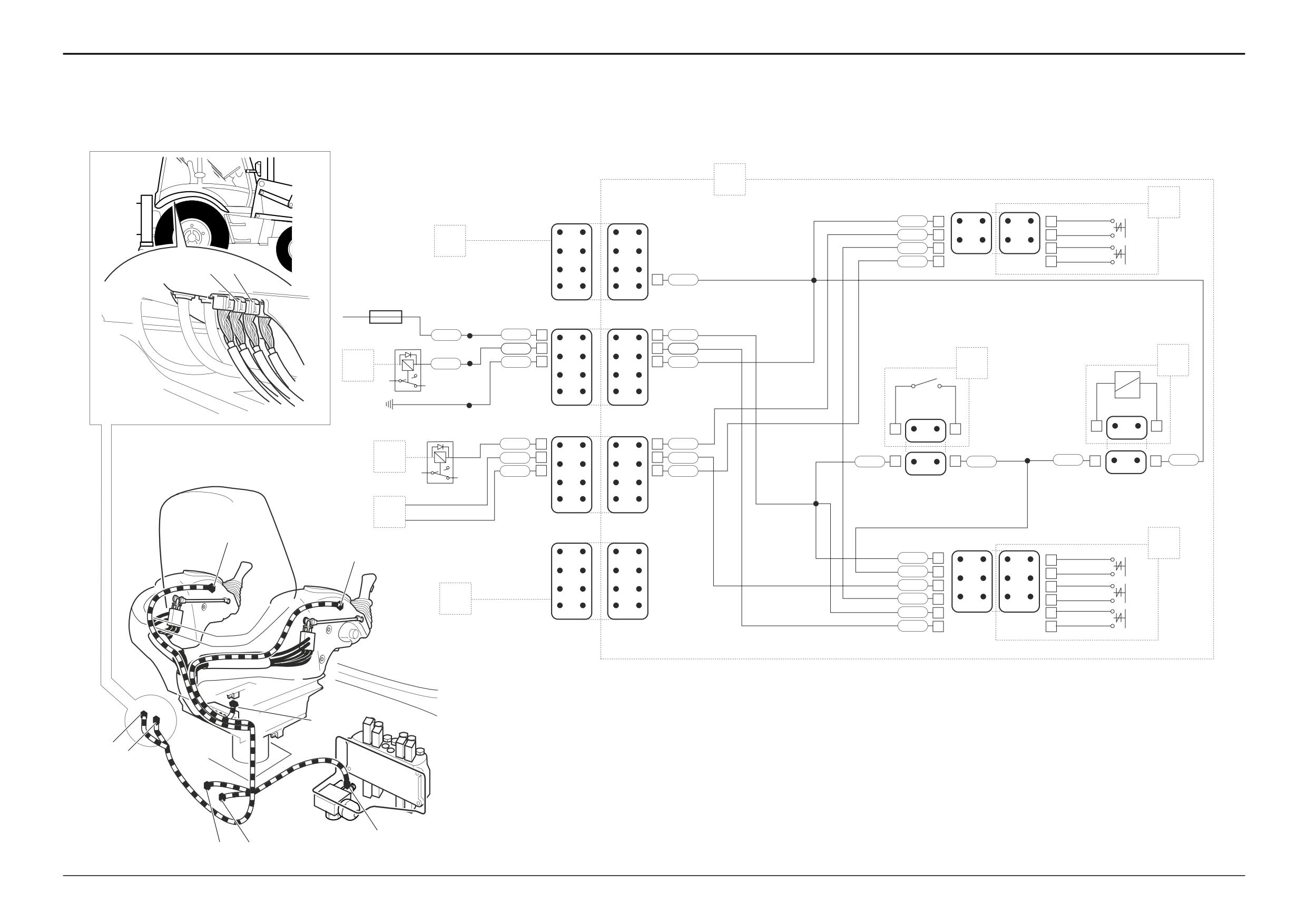
On the electrical diagram opposite the electrical connectors
(example, CTG to HB) are shown looking on the mating face
of each connector when they are disconnected.
The wire numbers and colours, where appropriate, are
shown as an aid to identification whilst fault finding.
Before fault finding make sure that you understand how the
the electrical circuits work. Most potential faults can be
traced using a multimeter to carry out continuity checks on
wires, switches and soleniod coils. See Service
Procedures, Electrical Testing Methods for more details.
Component Key:
Splices:
1
Servo harness
SA
HA Auxiliary hydraulics harness loop connector
SB
HB Auxiliary hydraulics connector
SC
HC Rear cab harness loop connector
SD
HD Rear cab harness connector
SH
HE Pilot control valve solenoid connector
TA
HF Right hand joystick connector
HG Seat microswitch connector
HH Left hand joystick connector
2
Right hand joystick
2a Microswitch - Mode
2b Microswitch - Excavator quickhitch latch control (if
fitted)
2c Microswitch - Hydraulic changeover solenoid valve
(if fitted)
3
Left hand joystick
3a Microswitch - Rear Horn
3b Microswitch - Excavator quick hitch latch control (if
fitted)
4
Seat mounted microswitch
5
Pilot control valve solenoid
6
Auxiliary hydraulics wiring harness, see Basic System
Operation, Circuit Schematics
7
Hydraulic change over circuit, see Basic System
Operation, Circuit Schematics, Auxiliary and
Hydraclamp Hydraulics
8
Rear horn circuit, see Basic System Operation, Circuit
Schematics
9
Dedicated quick hitch circuit, see Basic System
Operation, Dedicated Quick Hitch
10
Rear cab harness
A1
Fuse - Hydraulic Auxiliary
CP Relay base - Auxiliary (jaw bucket)
CMRelay base - Rear horn
9803/3280
Issue 1
Section D
Controls
Section D
37 - 1
Precision Control (Servo)
37 - 1
Fault Finding
Introduction
The fault finding procedures are given in the form of flow
charts. There are a number of charts, each one dedicated to
a particular fault. The charts are designed to identify
possible causes by performing checks and where
applicable, specific tests. Having identified a cause the
suggested remedy is given. The charts are designed to
identify causes through a process of elimination, starting
with the simplest, most easily rectified faults.
Before proceeding:
1
Make sure that the hydraulic fluid is at the correct
working temperature (50oC, 122oF).
2
Be sure to remove ALL contamination and if possible
identify its origin. It may be part of a component from
elsewhere in the circuit.
3
Replace any seals such as ‘O’ rings before assembling
hydraulic components.
Fault Finding Charts:
Chart A - No Servo Controls (system fails to operate)
Chart B - All Backhoe Services Slow to Operate
Chart C - One Backhoe Service fails or is Slow to Operate
Chart D - System Fails to Operate when the ‘Mode Switch’
is Activated (operator seat facing forward)
9803/3280
Issue 1
Section D
Controls
Section D
37 - 2
Precision Control (Servo)
37 - 2
Fault Finding
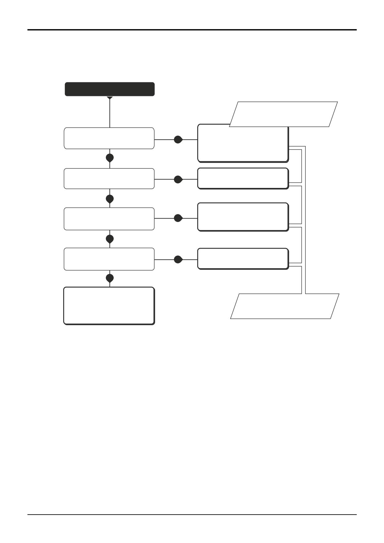
Chart A - No Servo Controls (system fails to operate)
START
See Electrical Switches, Seat
Mounted Microswitch - Adjustment.
Does system function if the 'mode'
Check seat mounted micro switch
switch is operated?
YES
function and condition of associated
wiring for damage. Repair or renew
as applicable.
NO
Is the supply valve solenoid coil
Renew coil.
YES
faulty?
NO
Inspect and test all relevant wiring
for damage and short circuits.
Is the relevant electrical fuse intact?
NO
Repair as applicable. Renew the
fuse.
YES
Is the wiring to the supply valve
Repair as applicable.
solenoid coil intact?
NO
YES
Renew pilot supply valve solenoid
See Electrical Connections.
valve stem.
A402360
9803/3280
Issue 1
Section D
Controls
Section D
37 - 3
Precision Control (Servo)
37 - 3
Fault Finding
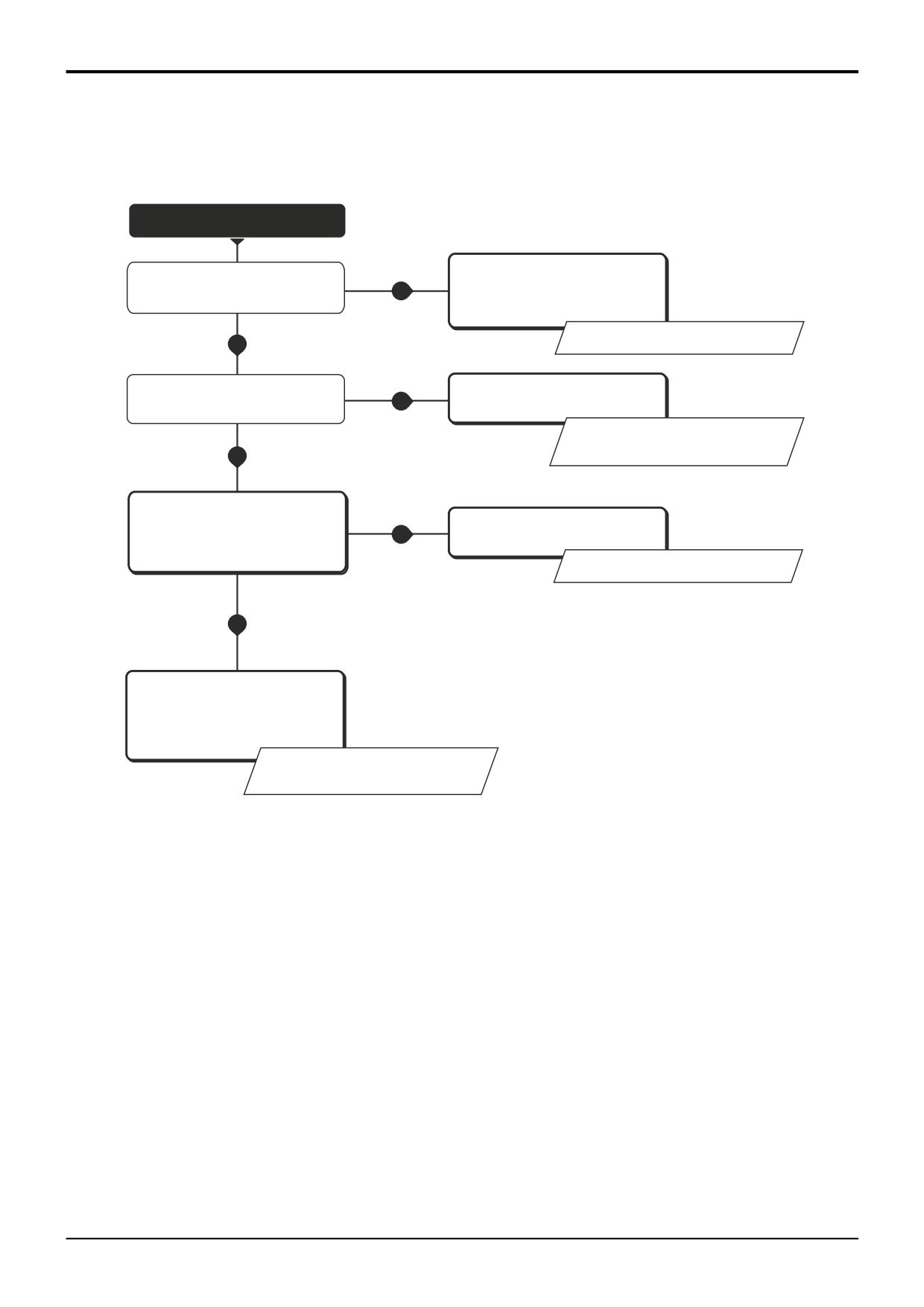
Chart B - All Backhoe Services Slow to Operate
START
Renew filter. Remove any
Is the pilot supply valve oil filter
contamination. Check condition of
blocked?
YES
hydraulic oil, drain and replace if
necessary.
See Section 3, Routine Maintenance.
NO
Is the pilot oil pressure low?
Adjust as required.
YES
See Service Procedures, Testing the
Pilot Pressure.
NO
Is the pilot supply valve operating
correctly? Remove the valve stem
YES
Repair or renew as applicable.
and check for signs of
NO
contamination or sticking.
See Electrical Connections.
YES
Are the joystick linkages worn? Check
the condition of the universal joints
and actuator plates on the pilot
control valves.
See Pilot Control Valves, Dismantling,
Inspection and Assembly.
A402370
9803/3280
Issue 1
Section D
Controls
Section D
37 - 4
Precision Control (Servo)
37 - 4
Fault Finding
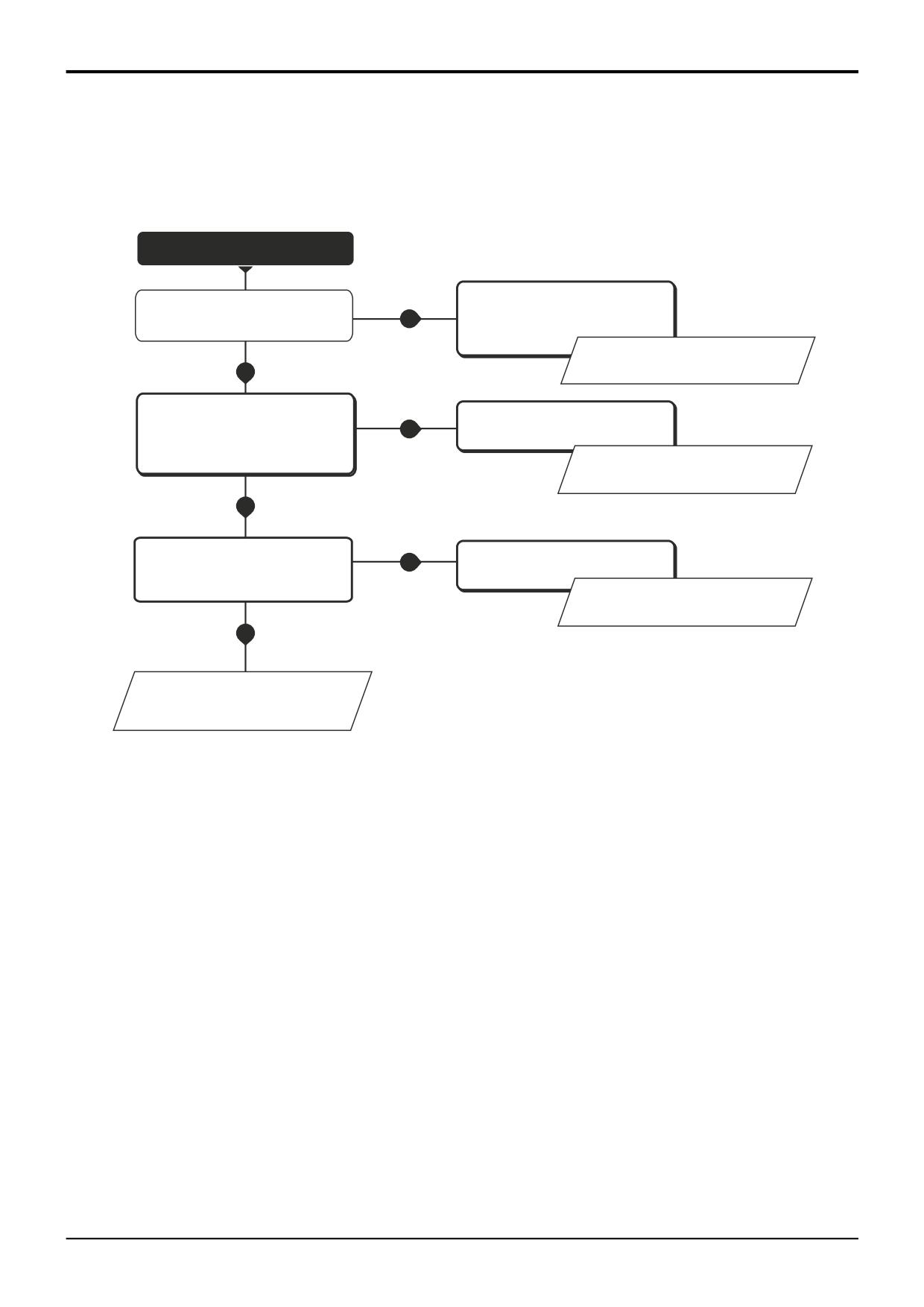
Chart C - One Backhoe Service fails or is Slow to Operate
START
Is the associated joystick mechanical
Renew or adjust components as
linkage worn or wrongly adjusted?
YES
applicable.
See Service Procedures, Control
Linkage Adjustment.
NO
Inspect the associated pilot spool
Clean and renew components as
valve capsule for signs of wear,
YES
applicable.
damage or contamination. Is the
valve in good working order?
See Pilot Control Valves, Dismantling
Inspection and Assembly.
NO
Is the associated service spool in the
YES
Rectify as applicable.
excavator valve sticking?
See Section E, Hydraulics Fault
Finding, ' A spool is sticking'.
NO
See Section E, Hydraulics Fault
Finding, ' One hydraulic service fails
or is slow to operate'.
A402380
9803/3280
Issue 1
Section D
Controls
Section D
37 - 5
Precision Control (Servo)
37 - 5
Fault Finding
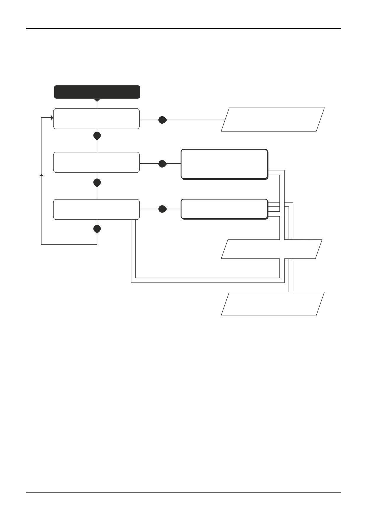
Chart D - System Fails to Operate when the ‘Mode Switch’ is Activated (operator seat facing forward)
START
Does the system operate with the
operator seat set in the rear facing
NO
See Fault Finding Chart A - No Servo
position?
Controls (system fails to operate)
YES
Check for damage and carry out
Is the relevant wiring damaged?
YES
continuity checks. Repair as
applicable.
NO
Is the mode switch functioning
NO
Test and renew switch if applicable.
correctly?
YES
See Electrical Connections.
See Electrical Switches, Joystick
Mounted Microswitches - Removal
and Replacement.
A402390
9803/3280
Issue 1
Section D
Controls
Section D
38 - 1
Precision Control (Servo)
38 - 1
Service Procedures
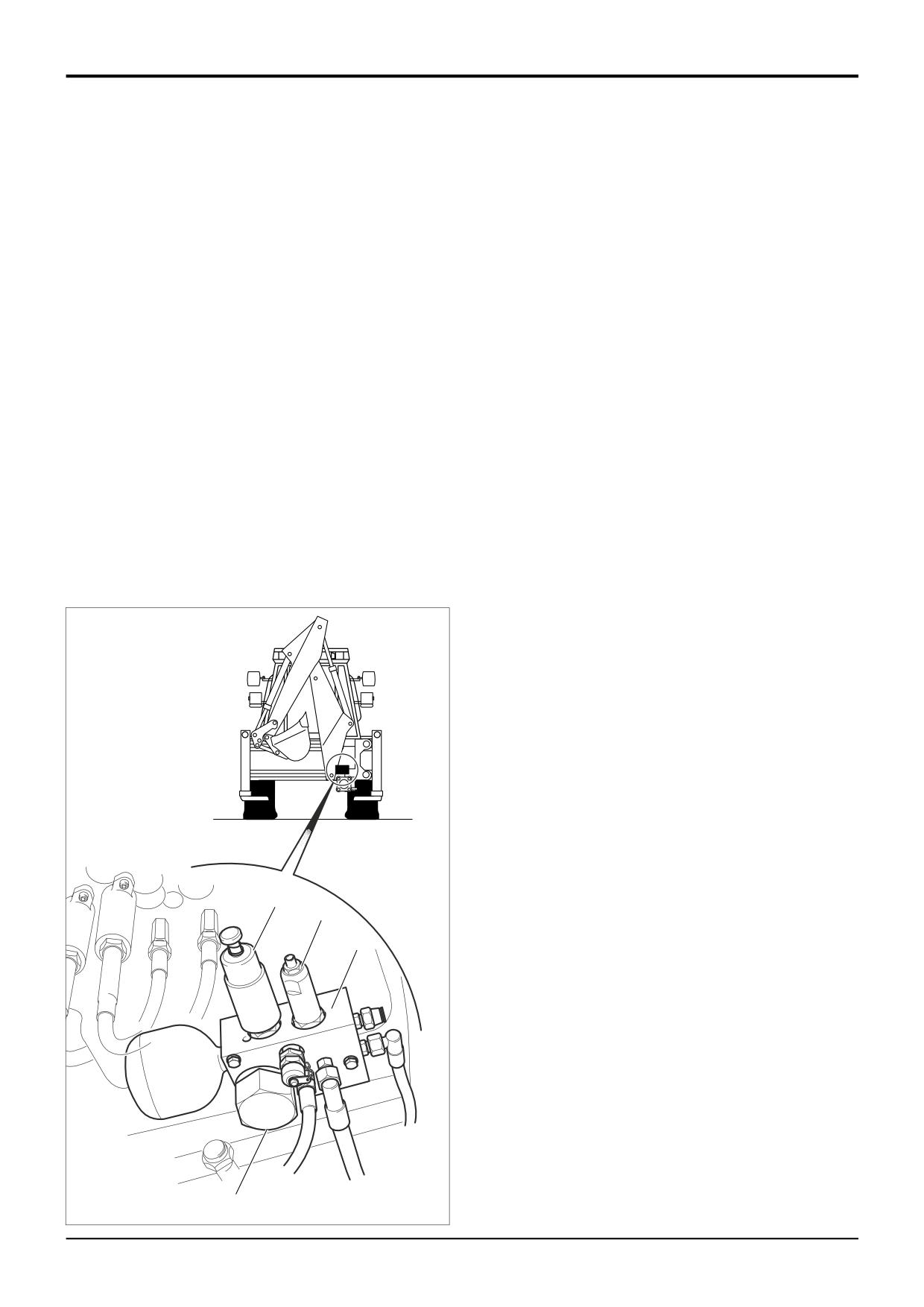
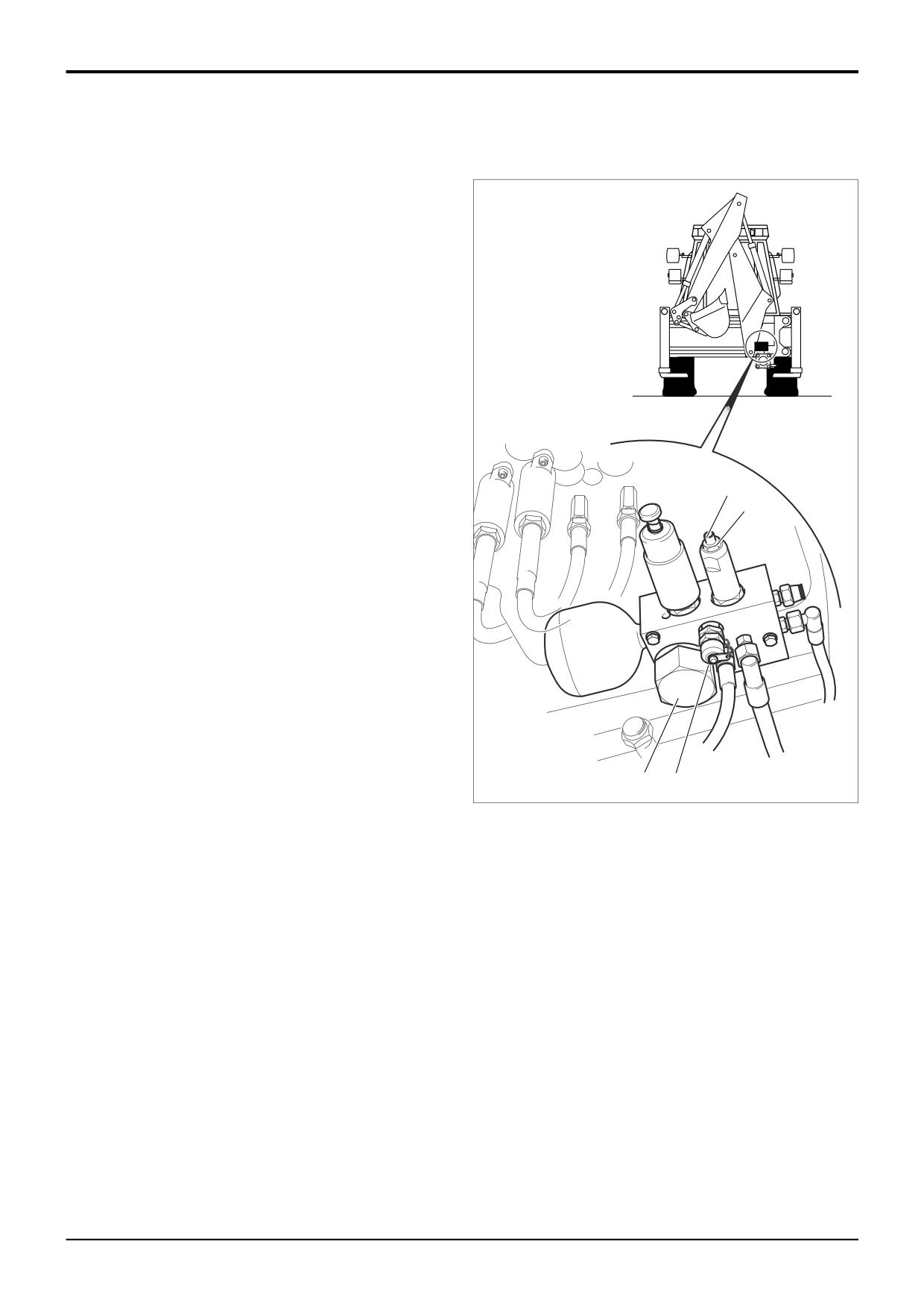
Testing the Pilot Pressure
1
Position the backhoe to enable access to the pilot
supply valve.
Before proceeding further the pilot circuit accumulator
pressure must be vented.
2
Stop the engine. With the operator seat set in the rear
facing position (for backhoe operation), switch the
starter to ON without starting the engine. Operate the
joystick controls several times to vent the servo
pressure from the accumulator. Switch the starter
switch to the OFF position.
3
Connect a 0 - 50 bar pressure gauge to the test point
A.
4
With the engine running at 1500 revs/min, operate a
C
backhoe service fully. At the same time check the
B
reading on the gauge. It should be 35 bar (36 kgf/cm2
507 lbf/in2).
If necessary adjust the pressure as follows:
1
Stop the engine. Loosen lock nut B and adjust screw C.
Turn screw C clockwise to increase pressure and anti-
clockwise to decrease the pressure. When the pressure
is correct, tighten the locknut and check the pressure
again. Adjust as required.
Renewing the Pilot Supply Valve Oil Filter
1
Position the backhoe to enable access to the pilot
A402080
supply valve.
D A
2
Stop the engine. Clean off all dirt on and around the
filter cap D. Undo the cap. Remove and discard the
filter element. The servo system is easily damaged by
contaminated hydraulic oil. When installing a new filter
element make sure that no dirt is allowed to enter the
pilot supply valve.
9803/3280
Issue 1
Section D
Controls
Section D
38 - 2
Precision Control (Servo)
38 - 2
D
D
F
A
D
C
E
A402430
B
9803/3280
Issue 1
Section D
Controls
Section D
38 - 3
Precision Control (Servo)
38 - 3
Service Procedures
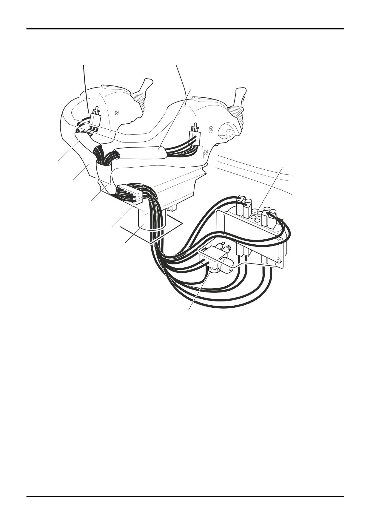
Pilot Hose Removal and Replacement
Before attempting to remove a servo hose the pilot circuit
accumulator pressure must be vented.
1
Stop the engine. With the operator seat set in the rear
facing position (for backhoe operation), switch the
starter to ON without starting the engine. Operate the
joystick controls several times to vent the servo
pressure from the accumulator. Switch the starter
switch to the OFF position.
2
Note the phasing and routing of the hose to be
renewed. Working under the machine, disconnect the
applicable hose. Note that the hoses have tags to
identify their connections. Plug the open ports. Remove
the hose from any ties under the machine.
3
Working in the cab remove the plastic shrouds A from
the seat as required. Disconnect the hose at the pilot
control valve B. Note that the hoses have tags to
identify their connections Attach some strong string or
cord to the end of the disconnected hose.
4
Undo the hose clamp C at the base of the seat frame.
5
Draw the hose up into the cab through pedestal E and
sleeves D. Undo the string from the end of the hose.
6
Make sure that the open ends of the new hose are
plugged. Tie the correct end of the hose to the string.
Draw the hose down through the sleeves D and
pedestal E.
7
Remove the string and connect the hose as applicable,
making sure to phase it correctly. Refit the hose clamp
C.
8
Tag the new hose at both ends to identify its
connections.
9803/3280
Issue 1
Section D
Controls
Section D
38 - 4
Precision Control (Servo)
38 - 4
Service Procedures
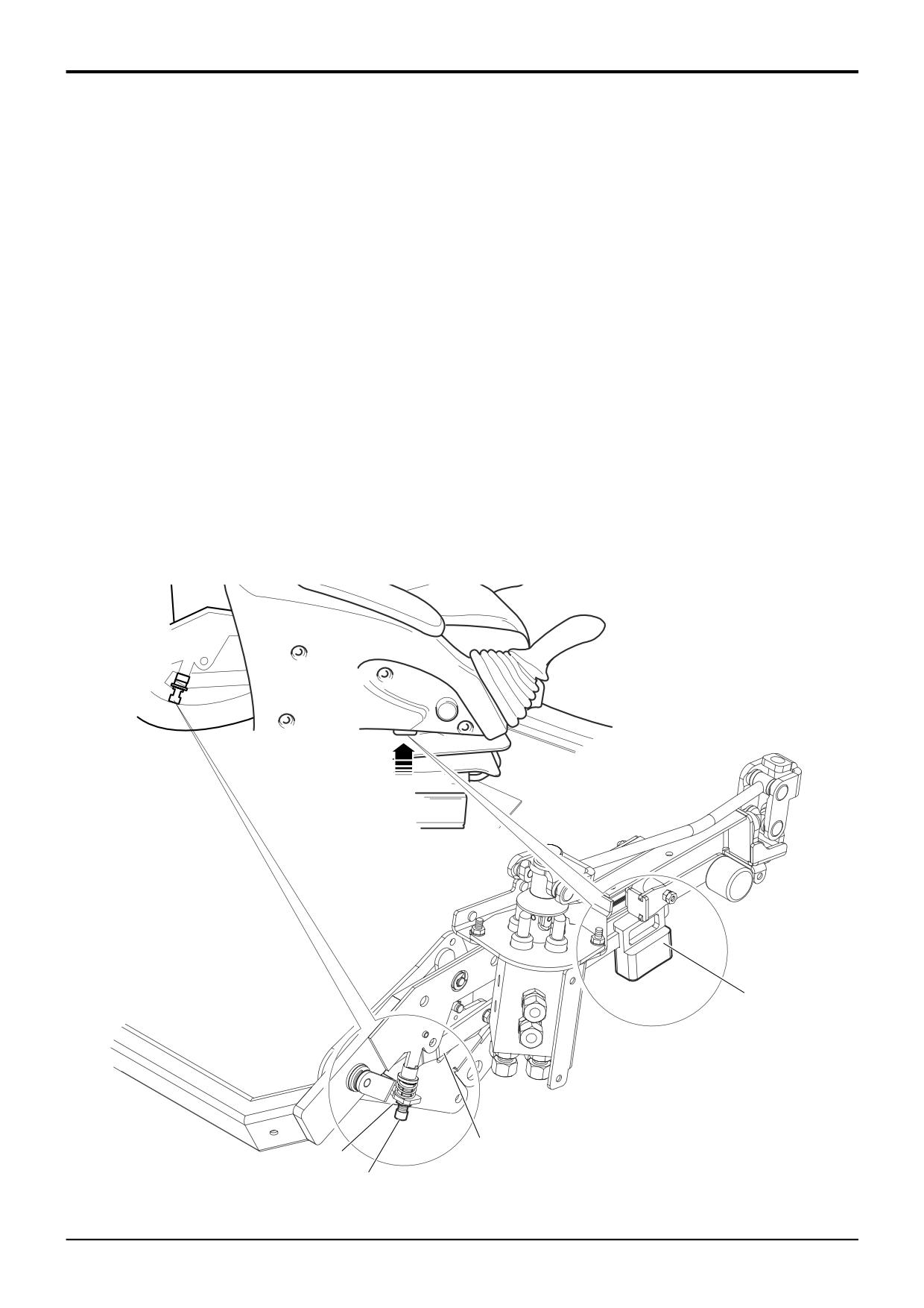
Seat Arms Control Lever - Adjustment
In some instances it may be necessary to adjust the
operation of the arms raise/lower control lever 1.
When the button 2 is depressed upwards fully, the arms are
released for raise/lower. If the arms are not released, or
release but re-lock when the button is fully depressed,
adjust the control lever as follows:
If the arms do not release
1
Slacken lock nut 3 and screw the stop bolt 4 out (anti-
clockwise). Test the operation of the control lever and
then tignten the lock nut 3.
If the arms release but re-lock
1
Slacken lock nut 3 and screw the stop bolt 4 in
(clockwise). Test the operation of the control lever and
then tighten the lock nut 3.
2
A402560
1
3
4
9803/3280
Issue 1
Section D
Controls
Section D
40 - 1
Precision Control (Servo)
40 - 1
4
2
3
1
1
9
10
5
6
8
8
A402540
7
9803/3280
Issue 1
Section D
Controls
Section D
40 - 2
Precision Control (Servo)
40 - 2
Pilot Control Valves
Removal and Replacement
Note that the procedure shows the right hand control valve.
The removal and replacement procedure for the left hand
valve is identical.
Before attempting to remove a pilot control valve the pilot
circuit accumulator pressure must be vented.
1
Stop the engine. With the operator seat set in the rear
facing position (for backhoe operation), switch the
starter to ON without starting the engine. Operate the
joystick controls several times to vent the servo
pressure from the accumulator. Switch the starter
switch to the OFF position.
Removal
1
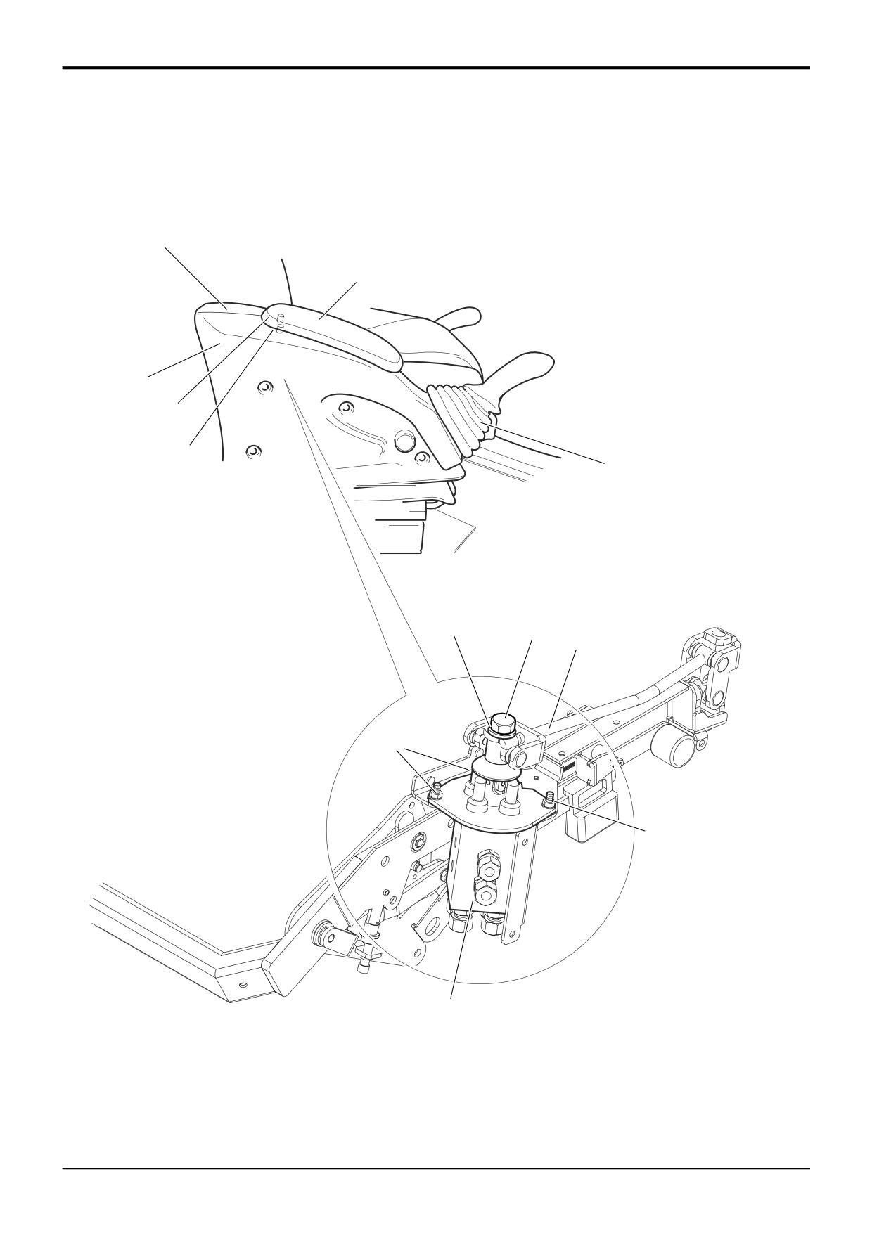
Reach inside the arm assembly and undo the two arm
rest fixing bolts 1. Carefully lift the rear of the arm rest 2
and pull it to the rear to release.
2
Undo the retaining screws and remove the plastic
covers 3 and 4. Undo and remove bolt 5 together with
lock washer 10. Lift the link rod 6 to one side.
3
Note the phasing of the hoses connected at the valve 7.
If the hoses are not already tagged, tie on your own
tags. Make sure you have recorded the connections
correctly, enabling correct re-connection when
replacing the valve. Disconnect the hoses at the valve.
Cap all open hoses and ports.
4
Undo the three fixing bolts 8 and lift out the valve.
Replacement
Replacement is the reverse of removal. Make sure that the
joystick gaiter 9 is correctly located.
9803/3280
Issue 1
Section D
Controls
Section D
40 - 3
Precision Control (Servo)
40 - 3
1
3
15
6
7
5
14
2
6
7
9
8
8
4
16
10
Y
11
5
A
B
Z
2
Z
2
X
A402440
9803/3280
Issue 1
Section D
Controls
Section D
40 - 4
Precision Control (Servo)
40 - 4
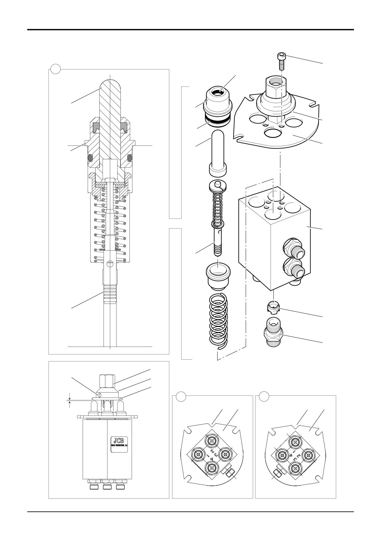
Pilot Control Valves
Dismantling, Inspection and Assembly
Note that the procedure shows the right hand control valve.
Assembly
The procedure for the left hand valve differs only in the
location of one way restrictors 4 and orientation of joint
Assembly is the reverse dismantling but note the following:
mechanism assemblies 2.
1
The valve assembly is susceptible to malfunction and
Dismantling
damage if it is contaminated with debris or dirt. Make
sure that all components are clean and free from
1
Undo the three cap screws
1. Lift off the joint
debris.
mechanism assembly 2.
2
Renew all ‘O’ rings 14 and seals 15.
2
Pull out the four valve capsule assemblies 3.
3
Be sure to fit the one way restrictors 4 the correct way
3
Remove the six adaptors 16 from the ports. Note that
up and in the correct ports. See Dismantling, Step 3.
the adaptors incorporate seals. Note that one way
restrictors 4 are fitted to some ports as follows:
4
Apply JCB HP Grease to the mating faces of wobble
Right hand valve - ports 1 and 3.
plate 5 and plungers 6.
Left hand valve - ports 2 and 4.
5
Be sure to orientate the joint mechanism assembly 2
Inspection
correctly. On left hand valves note that the slot Z aligns
with port 2 as shown at A. On right hand valves the slot
1
Inspect the underside of the wobble plate 5 for signs of
Z aligns with port 1 as shown at B.
excessive wear. If wear is evident the complete
assembly 2 must be renewed.
6
If the joint mechanism assembly 2 is to be renewed it
must be adjusted correctly. With the assembly fixed in
2
Inspect the universal joint for signs of excessive play. If
position, check the dimension X. The wobble plate 5
wear is evident the complete assembly 2 must be
must be positioned so that it just makes contact with
renewed.
the top of the valve plungers. If there is a gap at X, or if
the plate is depressing the plungers adjust as follows:
3
Inspect the mating faces of plungers 6 and bushes 7 for
Hold the collar 11 using a suitable rod located in hole Y.
signs of excessive wear. If wear is evident the valve
Slacken the lock nut 10 and then screw the collar 13 up
capsule must be renewed as a complete assembly.
or down as required. Tighten the lock nut 10.
4
If the valve has been contaminated with debris be sure
Torque Settings:
to remove it from all internal drillings. Carefully inspect
the mating faces of spools 8 and body 9. If scoring is
Item
Nm
Kgf m
lbf ft
evident the complete valve must be renewed.
1
9
1
7
10
9
1
7
5
Make sure that one way restrictors 4 are free from
16
30
3
22
debris.
9803/3280
Issue 1
Section D
Controls
Section D
41 - 1
Precision Control (Servo)
41 - 1
C
H
G
B
B
P
A
K
M
N
K
J
L
E
F
J
E
F
D
A402410
V
X
W
U
Z
A402590
9803/3280
Issue 1