JCB 3CX, 4CX, 214e, 214, 215, 217 & VARIANTS Backhoe Loader. Service Manual - page 14
Section E
Hydraulics
Section E
7 - 1
Circuit Descriptions
7 - 1
Loader Valve - Variable Flow
Operation
Component Key:
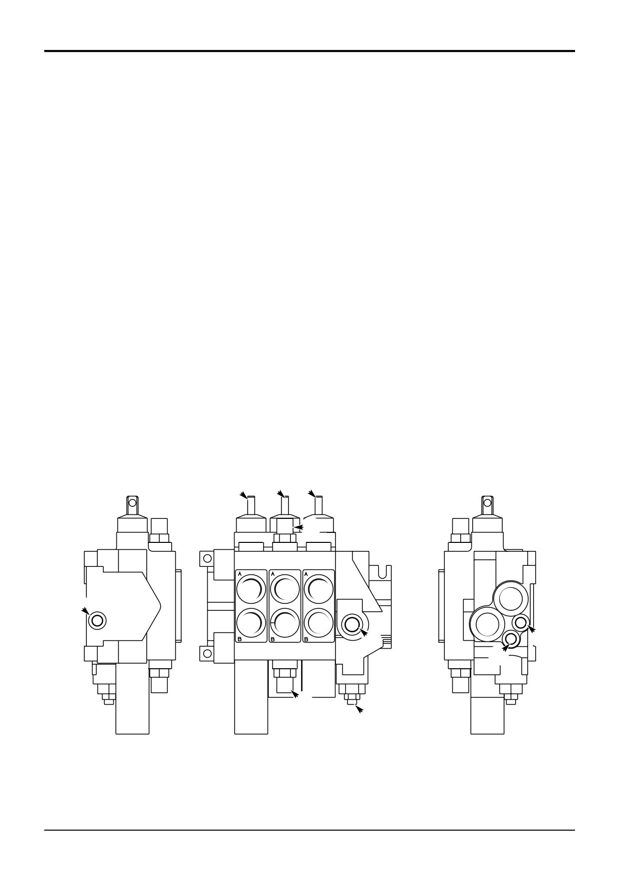
The loader valve is mounted on the chassis frame, right
1
Auxiliary (optional) spool
hand side (when viewed from rear).
2
Shovel spool
3
Arms lift spool
It is a stack type, directional control valve that is configured
4
Pump inlet
for closed centre operation. The valve block comprises two
5
Tank port
or three service valve sections and a priority steer inlet
6
Load sense port (from valve blocks)
section.
7
Priority load sense port (from steer unit)
8
Priority work port (to steer unit)
When operated, the designated valve section controls the
9
Load sense carry over port (to backhoe valve)
volume and direction of oil by way of service ports A or B. A
10
Service ports
constant flow is maintained regardless of changing load
11
Auxiliary relief valve (rods side)
pressures.
12
Auxiliary relief valve (head side)
13
Priority relief valve †
While the spools are in neutral position, the primary shuttles
and secondary shuttles are vented to tank. When a spool is
† Note: Steer circuit pressure is controlled by a relief valve
operated, the load pressure sensed at the work port is
housed in the hydraulic steer unit (refer to Section H
directed via the primary and secondary shuttles to the
Steering). The priority relief valve housed in the loader valve
hydraulic pump, where the pump subsequently ‘swashes’ to
must be set at 2500 lb/in2, this will ensure it does not
meet this load sense demand.
interfere with the operation of the relief valve housed in the
hydraulic steer unit.
3 21
!
0
0
0
4
9
0
0
0
5
6
8
7
@
£
A273670
9803/3280
Issue 1
Section E
Hydraulics
Section E
7 - 2
Circuit Descriptions
7 - 2
Loader Valve - Variable Flow
Priority Inlet Section Operation
Component Key:
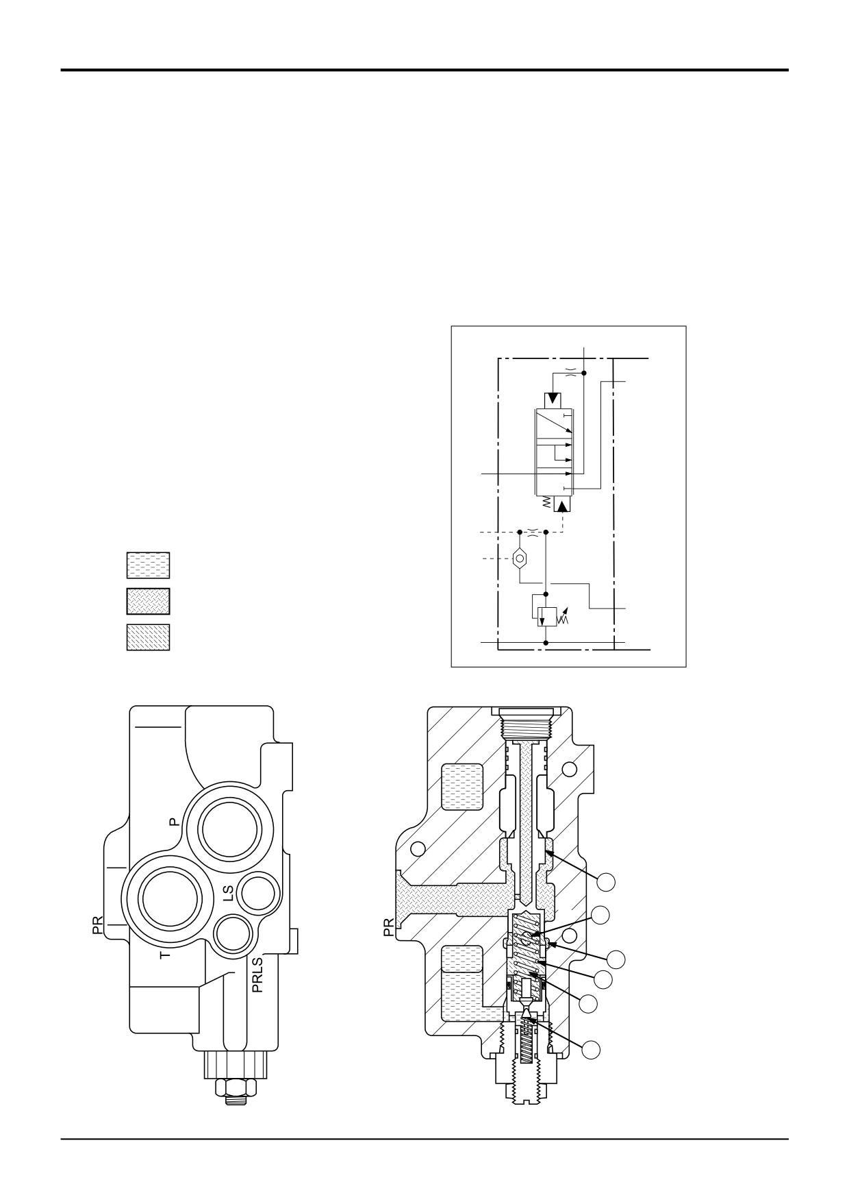
The priority inlet section houses the steering priority valve
P
Pump Inlet
and a relief valve assembly. Operation is as follows:
T
Tank
LS
Load sense port (to pump)
Steering
PRLS
Priority Load Sense Port (from steer unit)
When the steering wheel is turned, a priority pressure
PR
Priority Work Port (to steer unit)
demand signal is sent from the hydraulic steer unit and
received at the priority inlet section (port PRLS). The signal
oil flows through port A into chamber C via gallery B.
The combined force of spring D and signal oil pressure
PR
moves spool E up. The position of the spool now allows oil
from the pump inlet port P to flow out to the hydraulic steer
unit via priority work port PR.
It must be noted that relief valve assembly J is redundant.
This relief valve is part of the inlet section, however the
hydraulic steer unit also houses a steer system relief valve.
P
To ensure the relief valve in the hydraulic steer unit controls
the steer system pressure, valve J is set abnormally high
(172 bar; 2500 lb/in2).
PRLS
EXHAUST
LS
PUMP
T
LOAD SENSE
A273940
E
A
B
D
C
J
A273930
9803/3280
Issue 1
Section E
Hydraulics
Section E
7 - 3
Circuit Descriptions
7 - 3
Loader Valve - Variable Flow
Priority Inlet Section Operation
Component Key:
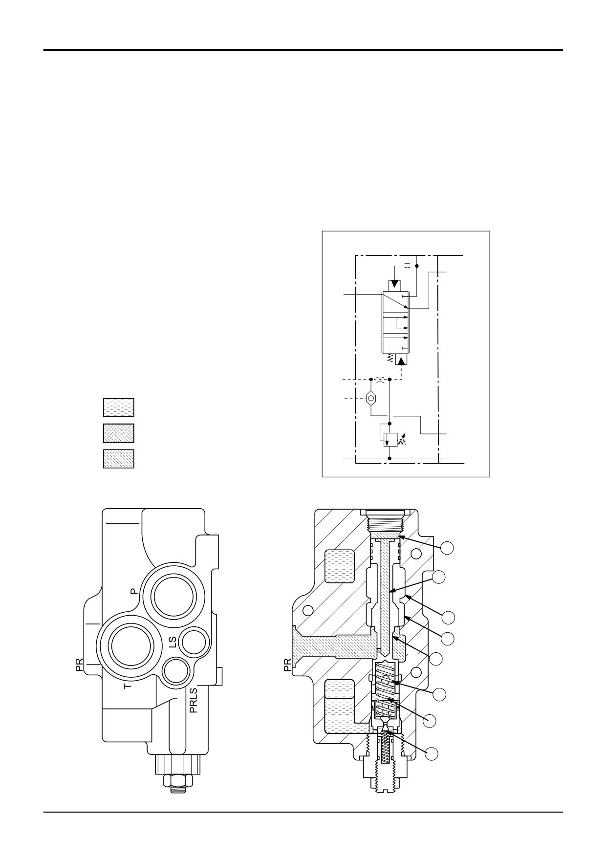
Service Selected (no steering demand)
P
Pump Inlet
If the steering is not selected, there will be no pressure
T
Tank
demand signal in chamber C. Pump pressure is ‘dead
LS
Load sense port (to pump)
ended’ at the steer unit, this pressure is felt in chamber F via
PRLS
Priority Load Sense Port (from steer unit)
priority port PR and drilling G. The pressure is sufficient to
PR
Priority Work Port (to steer unit)
force spool E down against the force of spring D. The
position of the spool now allows oil from the pump inlet port
P to flow into passage H and on to the selected service via
the valve block service ports.
PR
P
PRLS
EXHAUST
LS
PUMP
T
LOAD SENSE
A273970
F
G
H
4
E
D
C
J
A273980
9803/3280
Issue 1
Section E
Hydraulics
Section E
7 - 4
Circuit Descriptions
7 - 4
Loader Valve - Variable Flow
Auxiliary Spool
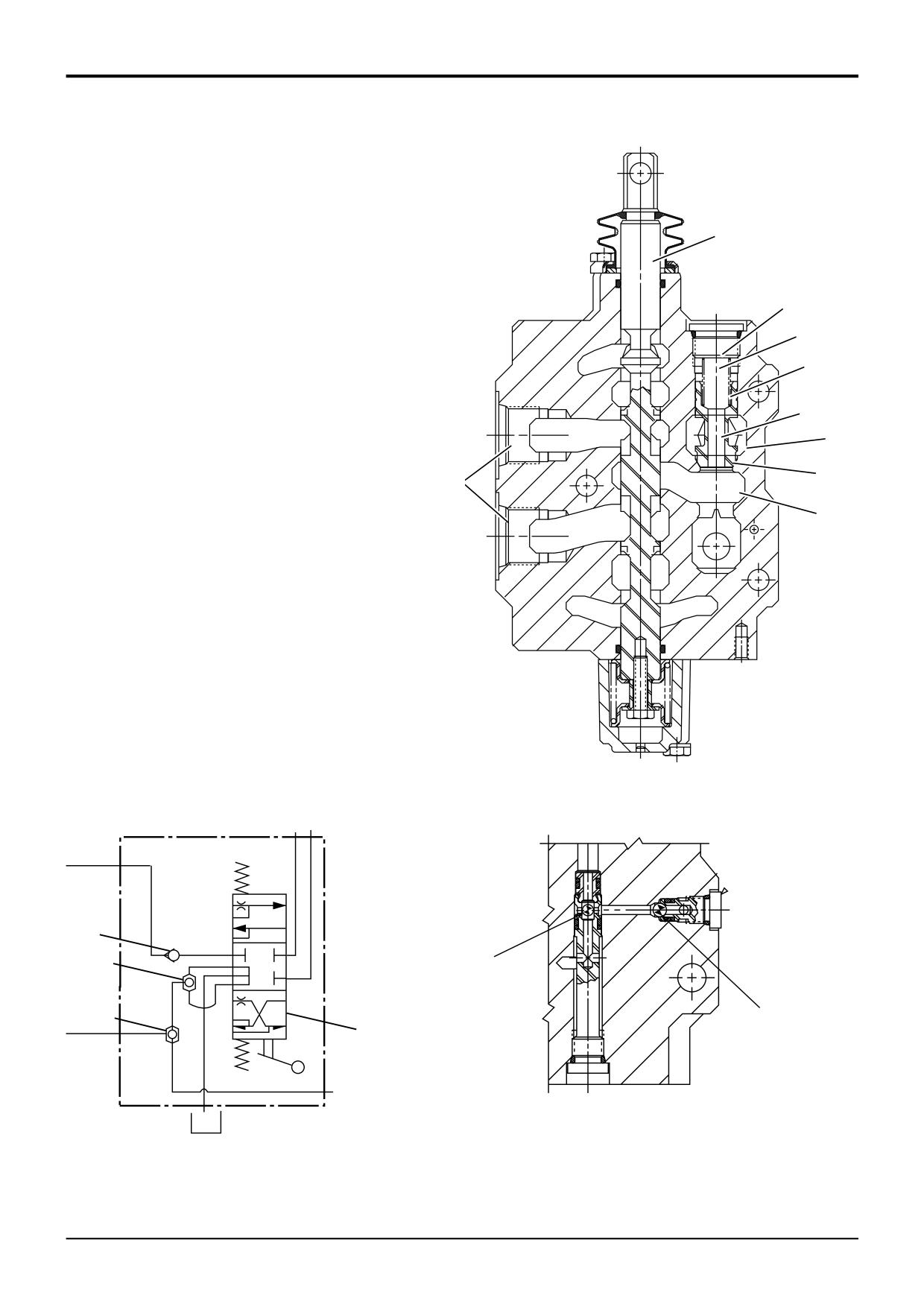
The auxiliary valve section comprises the spool assembly A,
A
load hold check valve assembly B, primary and secondary
shuttles, items L and K respectively.
While the spools are in neutral position, the primary shuttles
B
and secondary shuttles are vented to tank. When a spool is
operated, the load pressure sensed at the work port is
G
directed via the primary and secondary shuttles to the
hydraulic pump, where the pump subsequently ‘swashes’
E
and increases its output to meet this load sense demand.
When a service is selected (the spool moved up or down),
H
the waisted sections of the spool connect passage C to one
J
of the service ports D. Oil from the pump must overcome the
force of spring E to lift poppet F and make the connection
F
from the pump passage J to the service ports D via passage
C.
C
In some instances there is a back pressure in the service line
(e.g. generated by the weight of a loaded shovel). This
pressure is felt in chamber G via drilling H in poppet F. The
back pressure combined with the force of spring E keeps
the load hold check valve firmly closed, preventing the load
from dropping.
The pressure in pump passage J will increase until it is
greater than that in the service line. At this point, the load
hold check valve will open, as previously described.
A276100
PUMP
B
K
K
L
L
A
OAD
ENSE
A276290
9803/3280
Issue 1
Section E
Hydraulics
Section E
7 - 5
Circuit Descriptions
7 - 5
Loader Valve - Variable Flow
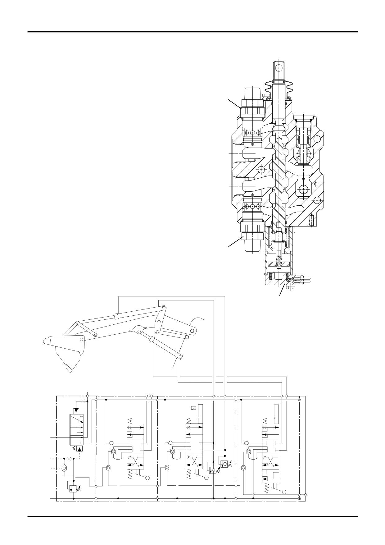
Loader Shovel Spool
The loader shovel spool operates in the same manner as the
30
auxiliary spool, refer to Auxiliary Spool.
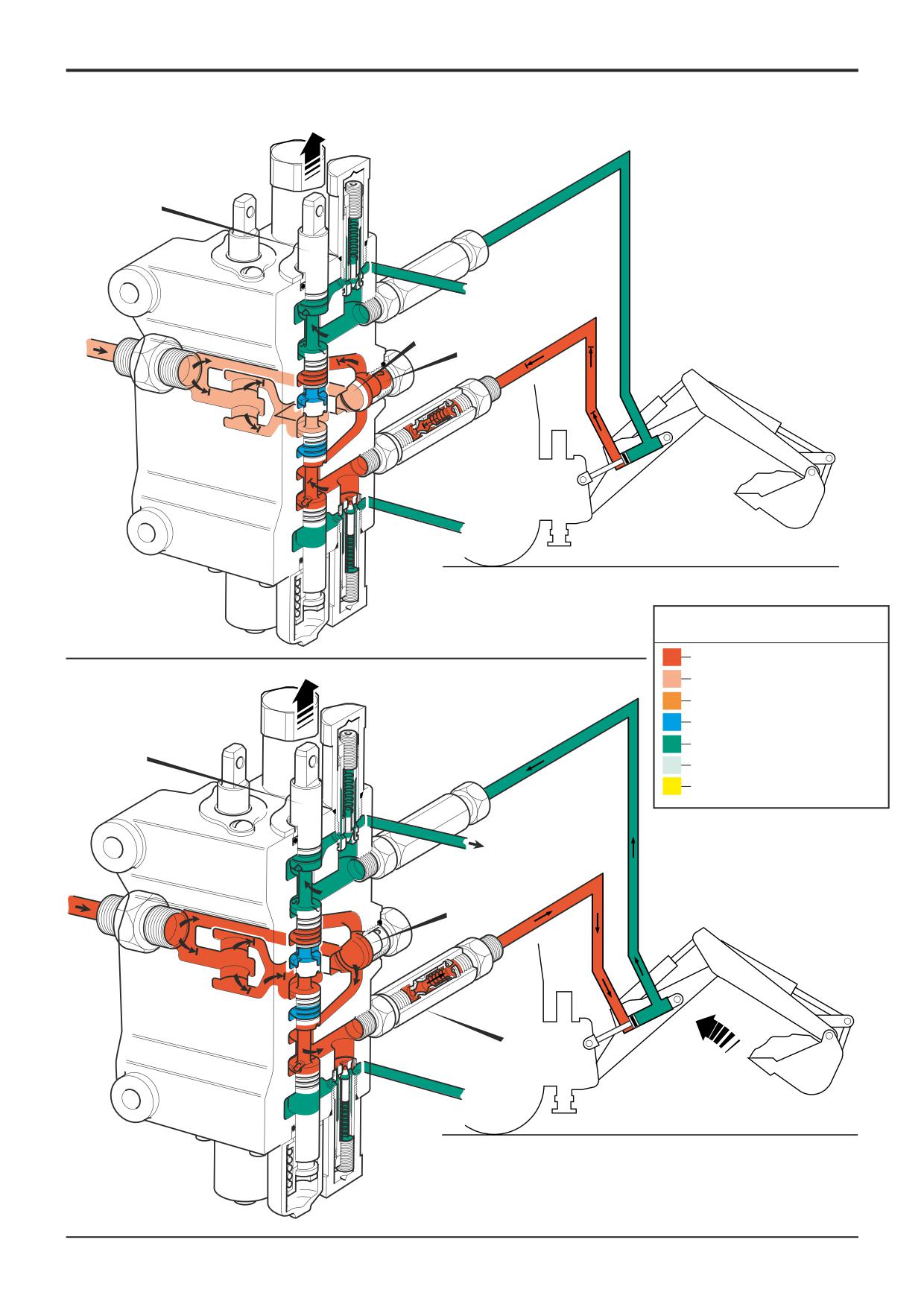
The shovel valve section also houses auxiliary relief valves
(items 30 and 30A).
Under normal operating conditions, with the shovel in the
'carry' position, the mechanical linkage keeps the shovel
level as the arms are raised, to prevent spillage of the load.
If, as illustrated, the shovel is fully tipped when the arms are
being raised, the shovel is unable to tip further, producing
back pressure in the head side of the shovel rams and
cavitation in the rod side.
As the arms continue to rise, the back pressure increases
until it reaches the setting of A.R.V. 30A. This A.R.V. then
opens, allowing the excess back pressure to be dumped to
exhaust and prevent the rams and linkage from being
damaged.
The rod side A.R.V. 30 senses a higher pressure in the
exhaust gallery than in the service port and therefore opens
30A
to allow exhaust oil to overcome the cavitation.
The shovel service may also be fitted with a ‘return to dig’
detent solenoid 12.
A278920
12
PR
P
PRLS
30
LS
30A
T
A279300
9803/3280
Issue 1
Section E
Hydraulics
Section E
7 - 6
Circuit Descriptions
7 - 6
Loader Valve - Variable Flow
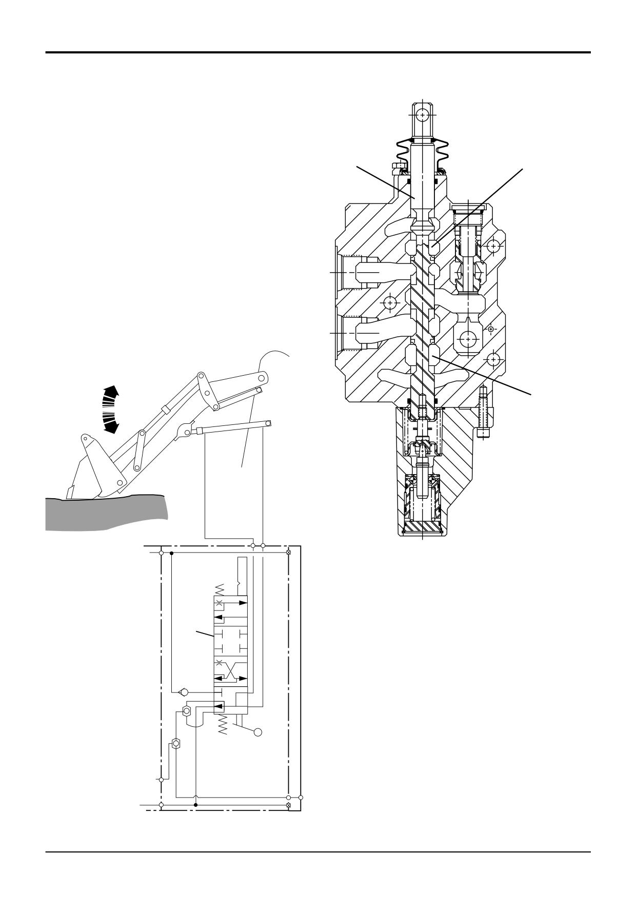
Loader Lift Spool
The loader lift spool operates in the same manner as the
18
A
auxiliary spool, refer to Auxiliary Spool.
The lift service spool (item 18) has a ‘float’ detent position.
The float facility is provided to allow the arms to move up
and down so that the shovel can follow the surface contours
as the machine is driven over uneven ground.
This is achieved by moving the lift spool 18 down beyond
'arms lower' into the 'float' detent. Both service ports are
connected to exhaust via the spool waists A.
Oil can then be displaced from either end of the lift rams and
into the exhaust gallery, allowing the rams to open and close
as required.
A
A278910
P
18
LS
T
A279430
9803/3280
Issue 1
www.WorkshopManuals.co.ukSection E
Section E
Hydraulics
7 - 7
Circuit Descriptions
7 - 7
Loader Valve - Variable Flow
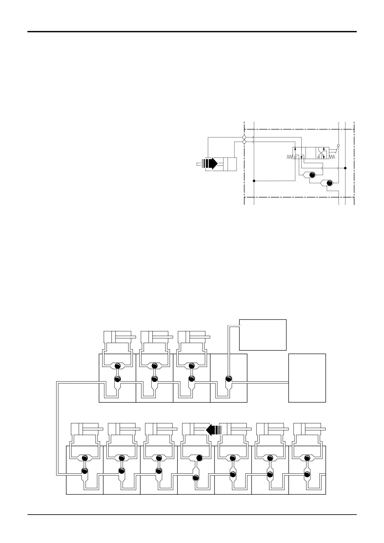
Shuttle Valve Signal Network
Each control valve section has two shuttle valves. Each valve
compares two pressure signals. One of the shuttles is the
primary 18 and the other is the secondary 17.
The primary shuttle 18 compares the pressure signal
between the two service ports A and B in each valve section,
the head and the rod pressure of the cylinder. In the example
A
shown the boom service 37 port B pressure signal is greater
30
B
than port A. Primary shuttle 18 moves across, the pressure
signal is the highest shuttle pressure. This signal pressure
passes to the next shuttle.
The secondary shuttle operates the same as the primary
37
18
shuttle but compares pressure signals between valve
sections.
17
The signal network is arranged in series. It starts at loader
P
LS T
valve block 9 inlet section which is connected to the steer
valve 45. The last secondary shuttle in the loader valve block
is connected to the first secondary shuttle in the backhoe
valve block 25. The highest shuttle signal pressure from the
loader valve block goes to the backhoe valve block.
The highest shuttle signal pressure is felt at the hydraulic
pump which instructs the pump to vary the output to meet
the highest shuttle load requirement. The stand-by pressure
spool in the pump adds margin pressure to the load
requirement. The single highest shuttle signal pressure plus
margin pressure governs pump output.
The pump will not change output until the shuttle network
identifies a different shuttle signal.
45
STEER VALVE
P
PUMP
9 LOADER VALVE
37
B A
18
17
A316510
25 BACKHOE VALVE
9803/3280
Issue 1
Section E
Hydraulics
Section E
8 - 1
Circuit Descriptions
8 - 1
Excavator Valve
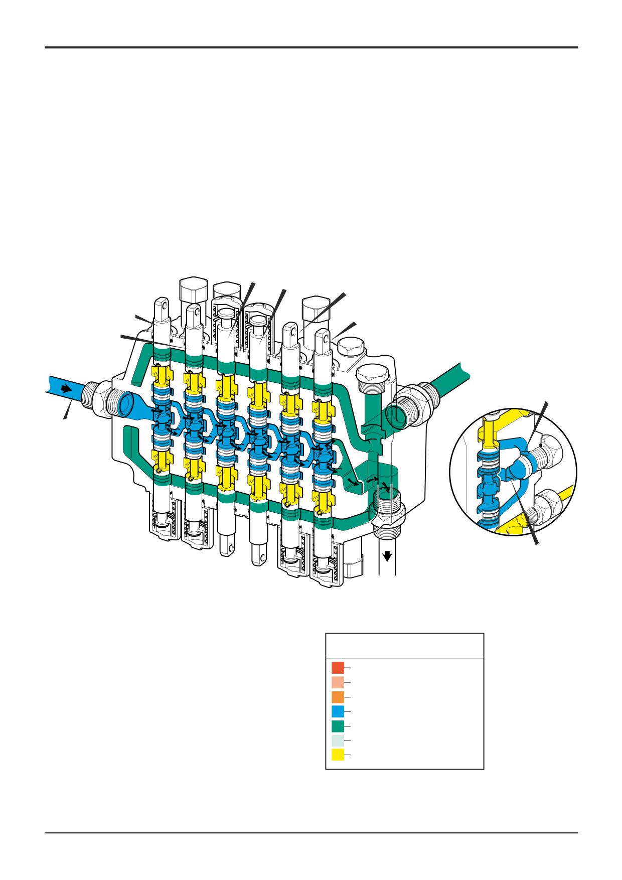
Manual Control - Neutral Circuit
Component Key: (JCB 'X' Control Pattern)
Oil from the loader valve enters the excavator valve at A
and flows through the neutral gallery and around the waists
A Inlet
of the solid spools. It also fills the parallel gallery B but is not
B Parallel Gallery
at a high enough pressure to open the load hold check
C Load Hold Check Valves
valves C.
4A Slew Spool
4B Boom Spool
4C Stabiliser Spool
4D Stabiliser Spool
4E Dipper Spool
4F Bucket Spool
Note: Machines with ISO control pattern have the boom and
dipper spools interchanged.
9803/3280
Issue 1
Section E
Section E
8 - 2
Circuit Descriptions
8 - 2
4C 4D4E
4A
4F
4B
C
A
A401190
B
Key to Oil Flow & Pressure
Full Pressure
Pressure
Servo
Neutral
Exhaust
Cavitation
Lock Up
A390630
9803/3280
Issue 1
Section E
Section E
8 - 3
Circuit Descriptions
8 - 3
4B
D
B
4S
A401200
Key to Oil Flow & Pressure
Full Pressure
Pressure
Servo
Neutral
Exhaust
4B
Cavitation
Lock Up
A390630
4S
E
A401210
9803/3280
Issue 1
Section E
Hydraulics
Section E
8 - 4
Circuit Descriptions
8 - 4
Excavator Valve - Load Hold Check Valves
Operation 1
Component Key:
B Parallel Gallery
Flow to the service via a typical solid spool 4B is controlled
D Service Line
by the load hold check valve 4S which is a spring-loaded
4B Spool
non-return valve operating across the pressure feed from the
4S Load Hold Check Valve
parallel gallery B. The valve prevents reverse flow from the
rams into the pressure feed line, so maintaining ram
pressure until exceeded by system pressure. The illustration
shows a service selected but back pressure D exceeds
system pressure which closes the load hold check valve 4S.
Operation 2
When pressure in the feed line exceeds back pressure, the
load check valve 4S opens and oil operates the ram. The
remaining load hold check valves are also opened by system
pressure but the galleries are dead-ended because the
spools are in neutral.
9803/3280
Issue 1
Section E
Hydraulics
Section E
8 - 5
Circuit Descriptions
8 - 5
Excavator Valve
- One Way Restrictor Operation
Componet Key:
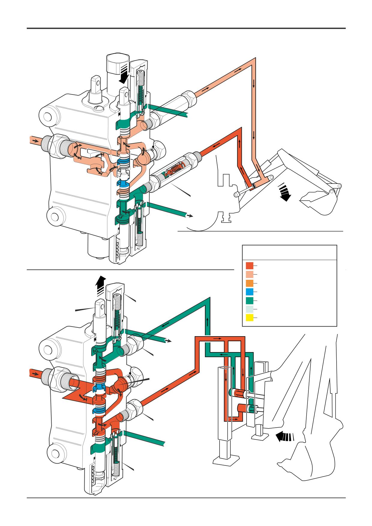
Because of its weight, the excavator end could take over
C Lower Service Port
control when boom lower was selected. The falling boom
D Upper Service Port
would tend to push oil out of the ram faster than the head
E One Way Restrictor
side was being filled. Consequently, when the excavator had
X Parallel Gallery
reached the ground, there would be a time lapse while the
4A Slew Spool
ram filled with oil before the service would operate again.
4B Boom Spool
4H ARV
To prevent this from happening, the boom service is fitted
4J ARV
with a one way restrictor. When the boom is being raised,
the poppet in restrictor E is held off its seat by the
pressurised oil flow, therefore oil delivery to the boom ram
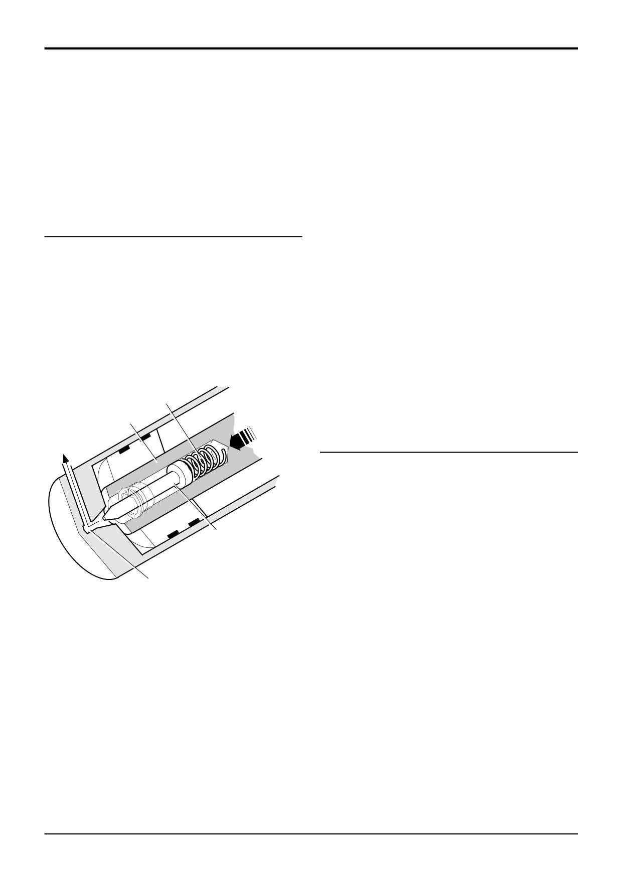
Slew Ram End Damping
rod side is unrestricted.
When the boom is being lowered, the oil flow through the
As ram A nears the closed position, damping rod B seats in
one way restrictor E re-seats the poppet, therefore the flow
cone C, where it is held by spring D. Tapered flutes on the
end of the rod produce a restricting orifice, thus restricting
of oil is restricted through the small drilling in the base of the
the speed of the oil being exhausted from the ram. This
poppet. This slows the boom down to a controllable speed.
provides a cushioning effect between the piston and the
dump end of the ram, effectively damping out the shock
loads which would otherwise occur when the boom reaches
the end of its slewing arc.
D
A
Excavator Valve - Slew Operation
The illustration shows R.H. slew selected. The lower port C
has been pressurised by the spool. Oil flows from the
parallel gallery B, out past A.R.V. 4H to both the head side
of the L.H. slew ram and the rod side of the R.H. slew ram.
B
The boom therefore slews to the right hand side of the
machine. Displaced oil from the rod side of the L.H. slew
ram and from the head side of the R.H. slew ram flows back
through the upper service port D and back to tank.
C
A230420
A Ram
B Damping Rod
C Cone Seat
D Spring
9803/3280
Issue 1
Section E
Section E
8 - 6
Circuit Descriptions
8 - 6
E
A396350
Key to Oil Flow & Pressure
Full Pressure
Pressure
Servo
Neutral
Exhaust
4J
Cavitation
4A
Lock Up
A390630
D
B
C
4H
A401220
9803/3280
Issue 1
Section E
Section E
8 - 7
Circuit Descriptions
8 - 7
4J
4A
4H
Key to Oil Flow & Pressure
Full Pressure
Pressure
Servo
Neutral
Exhaust
4E
Cavitation
4E 4F
4Q
Lock Up
4N
A390630
4M
4P
A396430
9803/3280
Issue 1
Section E
Hydraulics
Section E
8 - 8
Circuit Descriptions
8 - 8
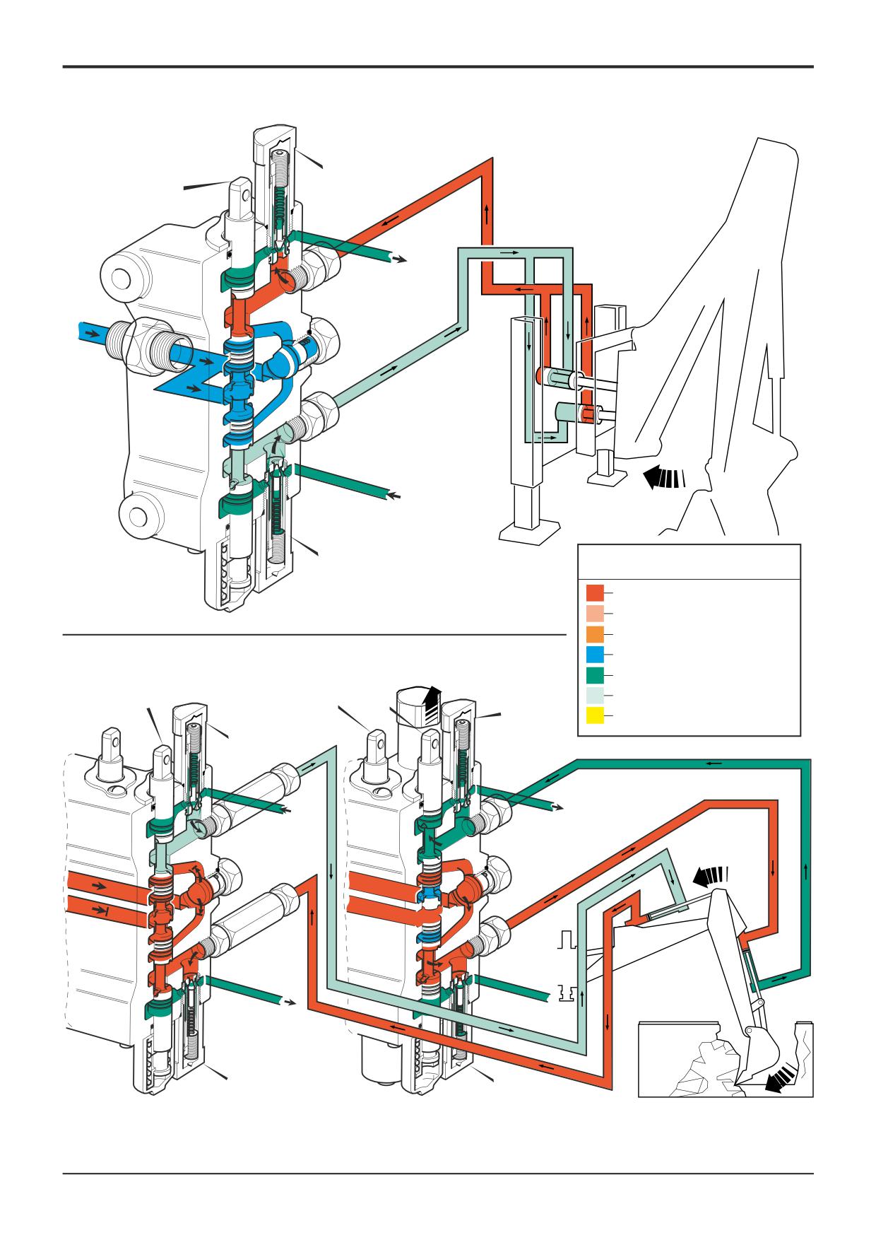
Excavator Valve - Slew A.R.V. and Anti-
Cavitation Operation
The spool 4A is in neutral but the momentum of the slewing
Componet Key:
excavator end creates back pressure in the head side of the
R.H. slew cylinder and in the rod side of the L.H. slew
4A Slew Spool
cylinder. This opens A.R.V. 4J and dumps oil to exhaust. At
4E Dipper Spool
this point the cylinders cavitate and exhaust oil pressure
4F Bucket Spool
causes A.R.V. 4H to open, allowing oil from the exhaust
4H ARV
gallery to fill the L.H. cylinder.
4J ARV
4M ARV
4N ARV
4P ARV
4Q ARV (option)
Excavator Valve - A.R.V. Operation
The illustration shows the bucket spool 4F selected to
operate the service against an immovable object. This forces
the dipper away from the obstruction and pressurises the
head side of the dipper ram.
When this pressure reaches the setting of A.R.V. 4M, this
valve opens, relieving the pressure into the exhaust gallery.
Cavitation occurs in the rod side of the dipper service until
A.R.V 4N opens, allowing the higher pressure in the exhaust
gallery to supplement that in the service line.
Note: A.R.V. 4Q is only fitted to machines with a
Rockbreaker.
For a further detailed description, refer also to Pilot -
Operated Pressure Relief Valve Operation.
9803/3280
Issue 1
Section E
Hydraulics
Section E
8 - 9
Circuit Descriptions
8 - 9
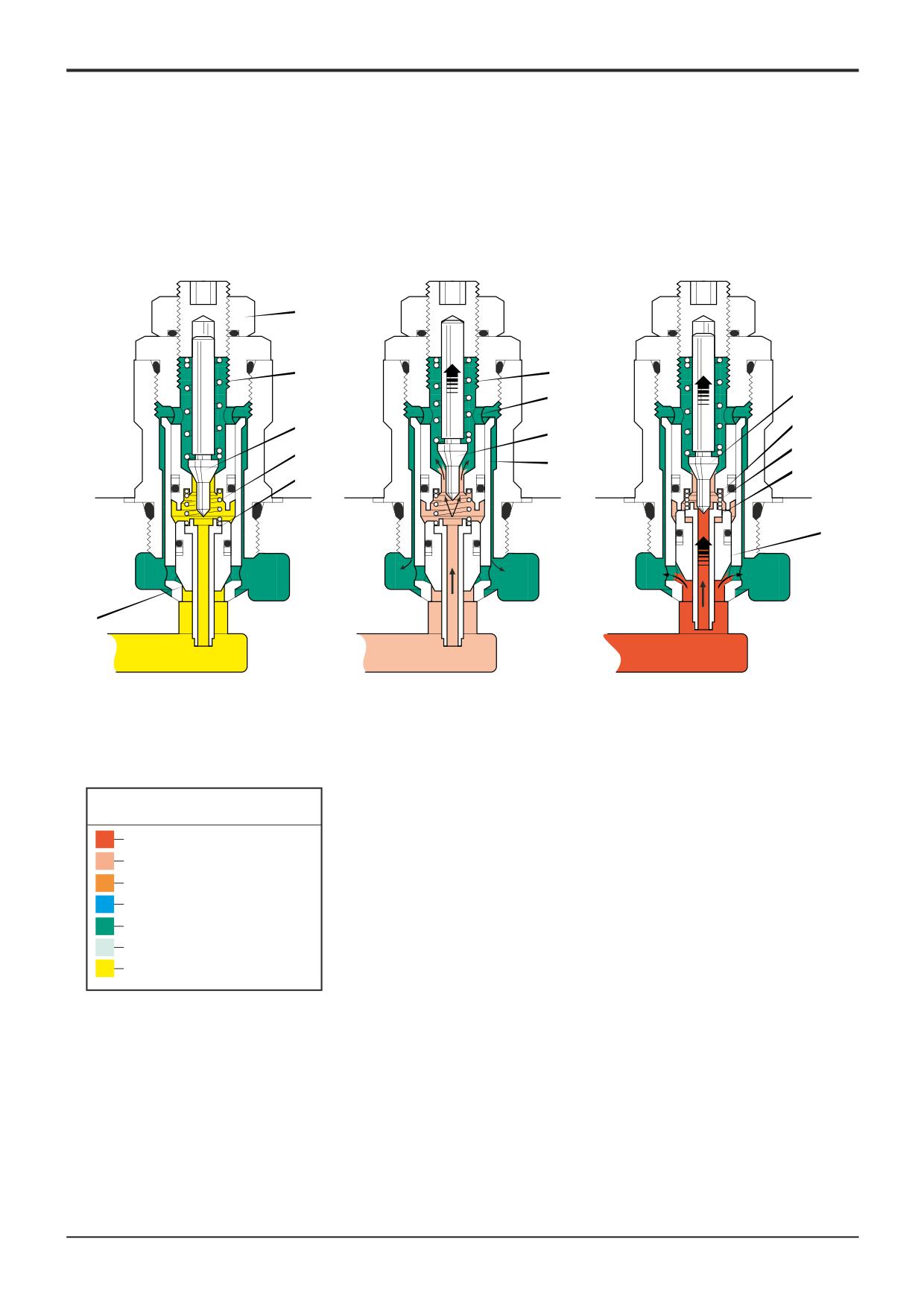
Pilot - Operated Pressure Relief Valve
Operation
Component Key:
1
Valve at Rest
A Service Pressure
A.R.V's are positioned in the excavator valve block in order
B Poppet
to relieve excessive pressure in the services as described in
C Piston
Excavator Valve - ARV Operation.
D Spring
E Poppet
When the service is in neutral and there are no excessive
F Spring
forces acting on the equipment, service pressure at A will be
G Locknut
acting on the lower face of poppet B and will also be felt
H Cavity
inside the valve via hollow piston C.
J Sleeve
K Exhaust Cavity
The force of springs D and F, combined with the service
L Cavity
pressure acting on the upper faces of poppet B and piston
C, keeps poppets B and E tightly seated.
The force of spring F is adjustable to suit the relevant service
by means of adjuster screw and locknut G.
2
Pilot Valve Opens
As service pressure reaches the pilot setting of the valve,
pilot poppet E lifts, allowing oil to escape into cavity H and
pass down the sides of sleeve J into the exhaust gallery K.
3
Main Poppet Opens
As service pressure continues to rise and oil escapes from
cavity L, the pressure differential between the upper and
lower surfaces of piston C causes this piston to rise and
seat on the point of pilot poppet E.
Oil continues to escape from cavity L but the incoming flow
to the cavity has been cut off. This produces a pressure
drop above poppet B, causing the poppet to lift and release
service pressure into exhaust gallery K.
9803/3280
Issue 1
Section E
Section E
8 - 10
Circuit Descriptions
8 - 10
G
F
F
E
H
E
L
E
D
D
J
C
C
B
K
K
K
B
A
A
A
1
2
3
A390480
Key to Oil Flow & Pressure
Full Pressure
Pressure
Servo
Neutral
Exhaust
Cavitation
Lock Up
A390630
9803/3280
Issue 1
Section E
Hydraulics
Section E
8 - 11
Circuit Descriptions
8 - 11
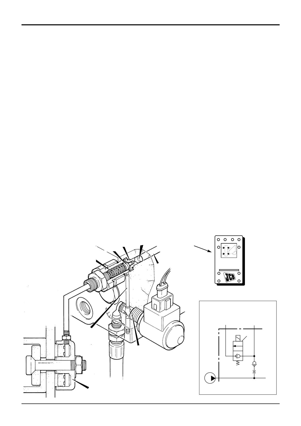
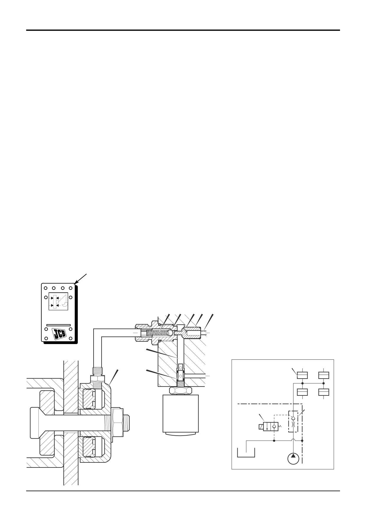
*Excavator Valve - Manual Control
Hydraclamp Valve Operation
(Sideshift Machines)
When the backhoe is being used for excavating duties, the
kingpost assembly must be 'clamped' to the sideshift
2 - Clamps Released - Not Precision Control Machines
rearframe.
When the hydraclamp switch A is in the ON position
(pressed down), the solenoid valve E is energised. The
The hydraclamp control valve assembly (items G, D and C) is
solenoid valve in this energised state now allows a
positioned in the inlet end of the excavator valve block and is
connection to be made from the parallel gallery B to the
connected directly to the parallel gallery B. The valve
drain port (tank) via gallery F.
operates in conjunction with solenoid valve E housed in the
side of the excavator valve block.
Oil from the hydra-clamps is vented through the clamp valve
and gallery F to the drain port (tank).
1 - Clamps Pressurised
When the hydraclamp switch A is in the OFF position (not
Also, pressure resulting from the operation of an excavator
pressed), the solenoid valve E is de-energised. The solenoid
service passes by poppet D as before but the oil takes the
valve in this de-energised state blocks the exhaust path from
path of least resistance and is vented via gallery F to the
the parallel gallery B to the drain port (tank).
drain port (tank).
When an excavator service is operated, pressure is
Restrictor H ensures that not all oil in gallery B is dumped
generated in parallel gallery B, this pressurised oil enters the
back to tank.
clamp valve C and lifts poppet D off its seat against the force
of spring G. The oil flows past the poppet and out to the
3 - Clamps Locked Up
hydra-clamps 62.
If no service is being operated, pressure in the parallel gallery
falls to that of the neutral circuit and the force of spring G is
sufficient to keep the poppet seated.
Pressure is therefore trapped in the line to the clamps,
maintaining the excavator end in a securely clamped
condition.
H
C
A
D
G
B
DRAIN
CLAMP
PORT
PORT
F
E
E
S270680
62
A270690
9803/3280
Issue 2*
Section E
Hydraulics
Section E
8 - 13
Circuit Descriptions
8 - 13
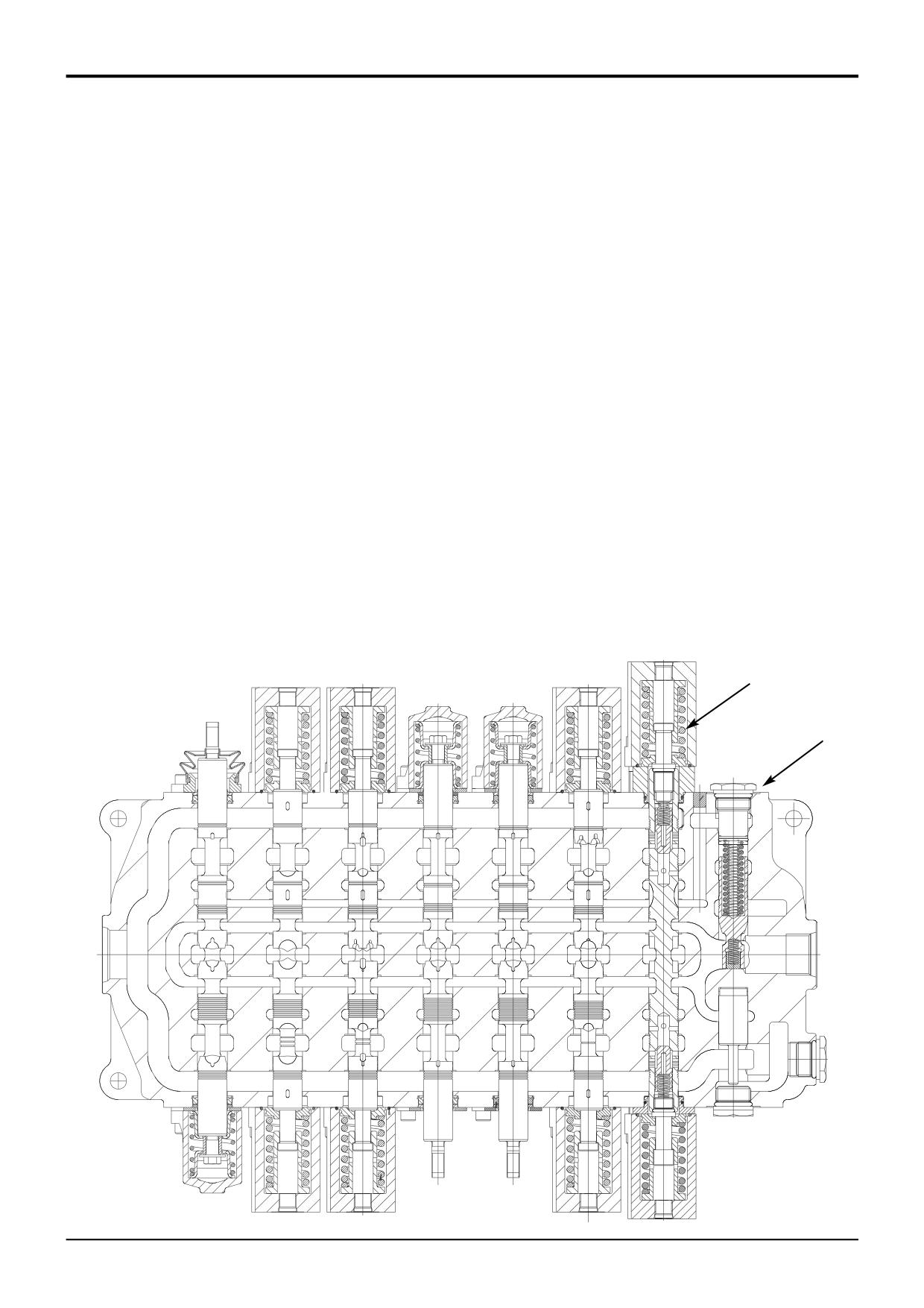
Excavator Valve
Precision Control (Servo)
(Machines up to serial no. 931159)
*
Component Key:
A Inlet Port
B Outlet Port
C Centering Spring
D Integral Load Sensing Valves (Isolator Compensator
Spools)
E Bypass Compensator Valve
F Load Sense Drain Regulator and Relief Valve
G Hydra-clamp Solenoid Valve
H Pilot Operated Check Valve
J Load Sense Drain Port
4A Slew Spool
4B Boom Spool
4C Stabiliser Spool
4D Stabiliser Spool
4E Dipper Spool
4F Bucket Spool
4G Aux. Spool (not used on some machine variants)
4A
4F
4E
4B
C
4D
4C
4G
E
B
A
A402510
9803/3280
Issue 2*
Section E
Hydraulics
Section E
8 - 14
Circuit Descriptions
8 - 14
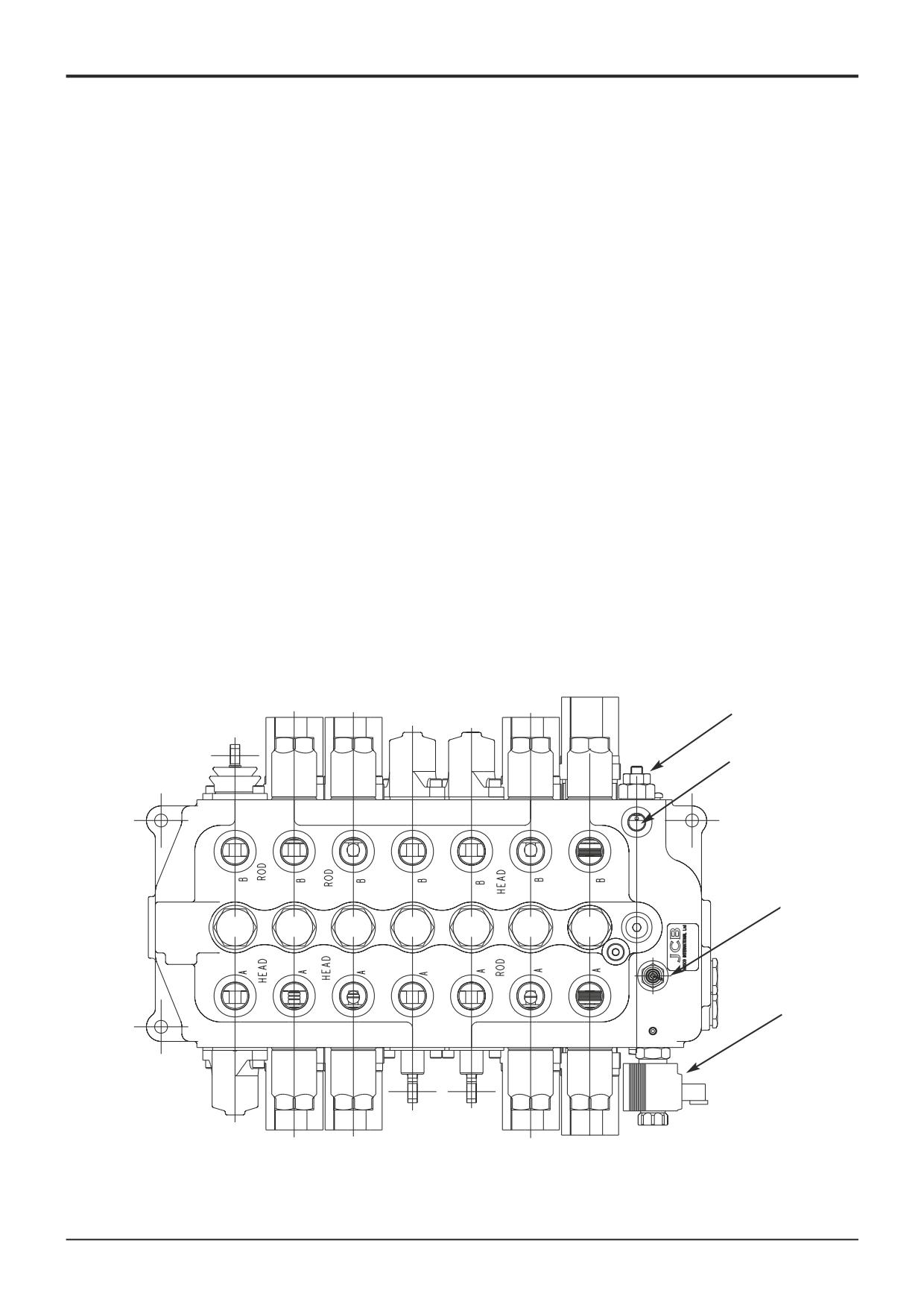
Excavator Valve
Precision Control (Servo) (continued)
*
(Machines up to serial no. 931159)
In the interest of machine efficiency and consistent backhoe
When a Service is Selected
operation the excavator valve is of a closed centre design
and incorporates load sensing valves D, for each service.
When one or more services are selected the load sense
These features enable the valve to operate as follows:
valves detect the service generating the highest pressure.
This causes the bypass compensator valve E to close and
No service is selected (all spools in neutral)
allow pump flow to the spools and service ports at sufficient
pressure to move the load. The load sense valves D also
Oil from the loader valve high pressure carry over enters the
incorporate check valves. These valves prevent the load
excavator valve at the inlet port A. Oil flows across the
falling back if the load pressure is greater than the pump
bypass compensator spool assembly E and returns to tank
pressure. The closed centre design ensures consistent
from the outlet port B.
service operation regardless of load.
Servo Spool Actuation
For a full description of spool and load sense valve operation
see Load Sense (Isolator Compensator) Valve Operation
When a service is operated servo pressure from the joystick
on the next page.
control valve acts on the end of the relevant service spool
Eg. 4A and displaces the spool proportionally against the
force of the centering spring C, allowing the oil to flow to
move the required service. When the servo pressure on the
end of the service spool is reduced the force of the centering
spring overcomes the servo pressure and the service spool
will move back proportionaly to the central neutral position.
Note that spools 4G, 4D and 4C are manually actuated.
F
J
H
D
D
D
D
D
D
D
G
A402500
9803/3280
Issue 2*
Section E
Hydraulics
Section E
8 - 15
Circuit Descriptions
8 - 15
2
LOAD = 100 bar
E1
20 bar
1
R
LS = 0 bar
3
E
T
P
5
PUMP = 20 bar
S
A402770
LOAD = 100 bar
2
1
R
E120 bar
4
LS = 20 bar
U
E
3
H
T
P
5
PUMP = 40 bar
S
A402780
LOAD = 100 bar
2
1
R
E120 bar
4
LS = 100 bar
U
E
H
3
T
P
5
Key to Oil Flow & Pressure
PUMP = 120 bar
S
Full Pressure
Exhaust
Pressure
Lock Up
Servo
Neutral
A402790
9803/3280
Issue 1
Section E
Hydraulics
Section E
8 - 16
Circuit Descriptions
8 - 16
Excavator Valve
Precision Control (Servo) (continued)
(Machines up to serial no. 931159)
*
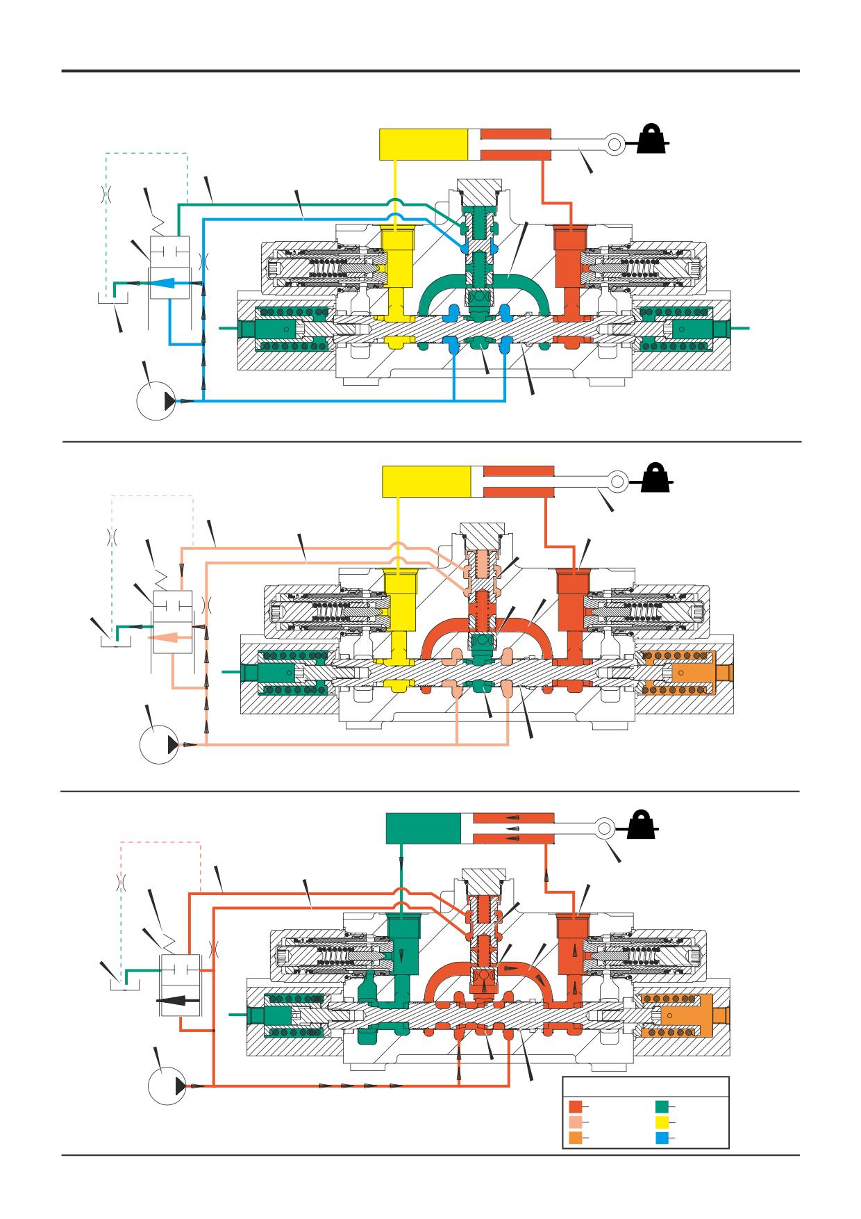
Load Sense (Isolator Compensator) Valve
Operation
No service is selected (all spools in neutral)
With the spools in the neutral position oil from the pump P
Any load on the service ram R is held by the main spool S.
flows to each spool and is dead ended. This generates
Oil is also vented to tank from the load sense gallery 2 via
sufficient pressure (about 20bar) to overcome the spring E1
the load sense drain regulator/relief valve F (see below).
and oil flows across the bypass compensator spool
assembly E to tank. Note that oil from the pump also flows
into the ‘auxiliary pump gallery’ 1. Oil from the ‘bridge
galleries’ 3 is vented to tank via a groove in the main spool S.
Spool at point of operating a service
Pressure from the load on ram R enters the bridge gallery 3
bleeds to tank, again causing pressure imbalance and the
via the service port 4. Compensator check valve H is held
isolator spool to move, allowing the pressure in the gallery to
down on its seat preventing the load moving. At the same
be ‘topped up’. This ensures that ‘pressure balance’ is
time the isolator spool U lifts and allows oil from the auxiliary
always maintained.
pump gallery 1 to flow into the load sense gallery 2. Oil
It must be noted that the load sense gallery 2 is connected to
pressure builds in gallery 1 and the bypass compensator
all load sense valves (one for each service). The pressure in
spool E begins to close under the action of the oil and spring
the gallery 2 will always be equal to the highest load from
(E1) pressure. This causes the pump pressure to rise to a
any of the backhoe services. The maximum load sense
new value as follows:
pressure is regulated by the load sense drain regulator/relief
Pump pressure = Pressure in load sense gallery 2 + pressure
valve F (see below).
from spring E1.
When the pressure in load sense gallery 2 reaches the load
pressure, isolator spool U moves down and closes off the
auxiliary pump gallery 1 from load sense gallery 2. If the load
pressure subsequently rises or falls, the isolator spool moves
due to pressure imbalance and maintains the pressure in the
load sense gallery 2 at the same pressure as the load
pressure. The pressure in the load sense gallery 2 always
Spool fully operating a service
As the spool S is moved further oil from the pump is diverted
into the central gallery 5. If the pump pressure has risen
F
sufficiently (to a pressure equal to the load + spring pressure
E1) then check valve H moves up off its seat and allows oil
to flow into bridge gallery 3, and out to the ram R via service
port 4. Exhaust oil from the other side of ram R is diverted to
tank.
9803/3280
Issue 2*
Section E
Hydraulics
Section E
8 - 17
Circuit Descriptions
8 - 17
Excavator Valve
Precision Control (Servo)
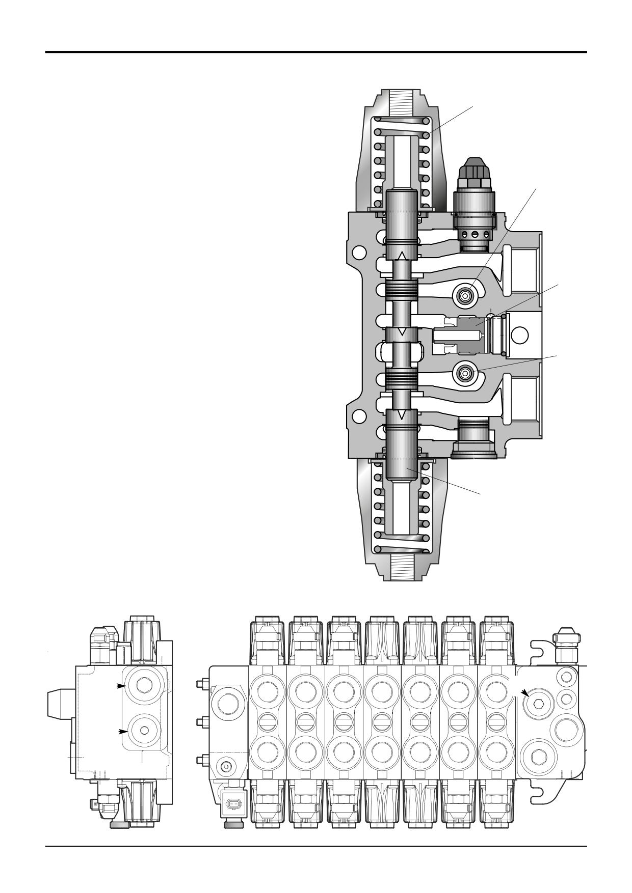
2 - Clamps Released - Precision Control Machines Only
*
(Machines up to serial no. 931159)
To enable clamps release, the hydraclamp switch A must be
in the ON position and an excavator service must be
Hydraclamp Valve Operation
operated.
When the backhoe is being used for excavating duties, the
With the hydraclamp switch A in the ON position (pressed
kingpost assembly must be 'clamped' to the sideshift
down), the solenoid valve E is energised. Pressure resulting
rearframe.
from the operation of an excavator service moves piston C
which pushes ball D off its seat.
The hydraclamp control valve assembly (items G, D and C) is
positioned in the front face of the excavator valve block and
With ball D lifted and the solenoid valve in its energised
is connected directly to the parallel gallery B. The valve
state, oil from the hydra-clamps is vented through the clamp
operates in conjunction with solenoid valve E located in the
valve and gallery F to the drain port T (tank).
bottom of the excavator valve block.
Also, pressure resulting from the operation of an excavator
1 - Clamps Pressurised
service passes through restrictor H. The oil takes the path of
When the hydraclamp switch A is in the OFF position (not
least resistance and is vented via gallery F to the drain port T
pressed), the solenoid valve E is de-energised. The solenoid
(tank).
valve in this de-energised state blocks the exhaust path from
the galleries B and F to the drain port T (tank).
Restrictor H ensures that only a small amount of oil from
gallery B is dumped back to tank.
When an excavator service is operated, pressure is
generated in parallel gallery B, this pressurised oil moves
3 - Clamps Locked Up
piston C which pushes ball D off its seat against the force of
If no service is being operated, pressure in the parallel gallery
spring G. The oil flows through restrictor H, past the ball and
falls to that of the neutral circuit and the force of spring G is
out to the hydra-clamps 62.
sufficient to keep the ball D seated. Pressure is therefore
trapped in the line to the clamps, maintaining the excavator
end in a securely clamped condition.
A
G
D
HC B
C
P
F
62
62
E
T
G
E
T
P
A402930
9803/3280
Issue 2*
Section E
Hydraulics
Section E
8 - 18
Circuit Descriptions
8 - 18
Excavator Valve
E
Precision Control (Servo) (continued)
(Machines from January 2003)
In the interest of machine efficiency and consistent backhoe
operation the excavator valve is of a closed centre design
G
and incorporates pressure compensating valves F, for each
service.
These features enable the valve to operate as follows:
No service selected (all spools in neutral)
T
Oil from the loader valve high pressure carry over enters the
excavator valve at the inlet port A. Oil flows across the
flushing valve spool assembly B and returns to tank from the
outlet port C.
F
Servo Spool Actuation
LS
When a service is operated servo pressure from the joystick
control valve acts on the end of the relevant service spool D
and displaces the spool proportionally against the force of
the centering spring E, allowing the oil to flow to move the
P
G
required service. When the servo pressure on the end of the
service spool is reduced the force of the centering spring
overcomes the servo pressure and the service spool will
move back proportionaly to the central neutral position.
When a Service is Selected
When one or more services are selected the pressure
T
compensator valves F detect the service generating the
highest pressure. This causes the flushing valve spool B to
close and allow pump flow to the spools and service ports at
sufficient pressure to move the load. Load hold check valves
G prevent the load falling back if the load pressure is greater
D
than the pump pressure. The closed centre design ensures
consistent service operation regardless of load.
For a full description of spool and pressure compensator
valve operation see Load Sense - Pressure Compensator
Valve Operation.
A405000
A
A
A
A
A
A
A
T1
C
B
T
LS
T3
A
P
P
C
M
B
B
B
B
B
B
B
A403680
9803/3280
Issue 1
Section E
Hydraulics
Section E
8 - 19
Circuit Descriptions
8 - 19
Excavator Valve
Precision Control (Servo) (continued)
(Machines from January 2003)
Load Sense - Pressure Compensator Valves
Operation
No service selected (all spools in neutral)
With the spools in the neutral position oil from the pump P
flows to each service spool S and is dead ended. This
generates sufficient pressure (about 15bar) to overcome the
spring E1 and oil flows across the flushing valve spool
assembly E to tank T. Any load acting on the service ram R
is held by the service spool S.
Oil in the load sense gallery LS is vented to tank across the
flow regulator valve F.
The pressure compensator valve PC and load hold check
valves CV are closed.
Operating a service
The service spool S is moved by servo pressure connecting
the oil from the pump P to the gallery P1. The pressure in
this chamber opens the pressure compensator valve PC
allowing oil into the load sense gallery LS. Oil pressure builds
in the gallery LS and the flushing valve spool E begins to
close under the combined action of the oil pressure and
spring force, causing the pump pressure to rise as follows:
Pump pressure = Pressure in load sense gallery LS +
pressure from spring E1.
When the pump pressure has risen sufficiently i.e. to a
pressure equal to the load + spring pressure (15 bar) the load
hold check valve CV moves off its seat and allows oil to flow
into the service gallery A, initiating movement of the service
ram R. Exhaust oil from the other side of the service ram is
directed by the service spool S to tank.
The maximum load sense pressure and hence pump
pressure is set by the load sense relief valve G.
9803/3280
Issue 1
Section E
Hydraulics
Section E
8 - 20
Circuit Descriptions
8 - 20
M
P
LS
R
P
F
E
CV
E1
A
B
T
PC
LS
T1
T
Key to Oil Flow & Pressure
S
Full Pressure
Pressure
Servo
Neutral
A405030
Exhaust
Cavitation
Lock Up
A390630
M
P
LS
R
P
G
E
CV
E1
A
B
T
PC
LS
T1
T
S
P1
A405040
9803/3280
Issue 1