JCB 3CX, 4CX, 214e, 214, 215, 217 & VARIANTS Backhoe Loader. Service Manual - page 16
Section E
Section E
Hydraulics
15 - 11
Fault Finding
15 - 11
PROBLEM:
Leaks between sections.
POSSIBLE CAUSE:
1) Missing or cut seals.
CORRECTIVE ACTION:
1) Disassemble valve stack and check for missing or cut o-rings.
PROBLEM:
Sticking spool.
POSSIBLE CAUSE:
1) Linkage binding. 2) Damaged spool. 3) Uneven torque of tie-rod. 4) Incorrect number of shims
on tie-rods.
CORRECTIVE ACTION:
1) Check linkage. 2) Remove and inspect spool. 3) Loosen tie-rod bolts, check and re-torque. 4)
Disassemble and check that each tie-rod has one shim.
PROBLEM:
Mechanical detent will not hold.
POSSIBLE CAUSE:
1) Broken detent shaft.
CORRECTIVE ACTION:
1) Remove detent & inspect.
PROBLEM:
Electrical detent will not hold.
POSSIBLE CAUSE:
1) Current broken.
CORRECTIVE ACTION:
1) Check current going into detent.
PROBLEM:
Poor performance, slow operating speed and/or low maximum stall speed.
POSSIBLE CAUSE:
1) Blocked flow regulator spool.
CORRECTIVE ACTION:
1) Flow check, remove and clean flow regulator valve, refer to Service Procedures, Variable
Flow Pumps - Regulator Valve Adjustment.
9803/3280
Issue 1
Section E
Hydraulics
Section E
15 - 12
Fault Finding
15 - 12
Smooth Ride System
Fault
Probable Cause
Action
1
Unable to power down loader arms
Rod side solenoid valve open.
Check if solenoid operating, replace
with system switched OFF.
solenoid or selector valve as required.
2
Restricted loader arm suspension
Rod side solenoid valve closed.
Check if solenoid operating, replace
movement when switched ON.
solenoid or selector valve as required.
3
Springy loader arm lift with system
Head side solenoid valve open.
Check if solenoid operating, replace
switched OFF.
solenoid or selector valve as required.
4
No suspension, unable to power down
Head side solenoid valve closed.
Check if solenoid operating, replace
when switched ON.
solenoid or selector valve as required.
5
Accumulator gas pressure decrease.
Leak across accumulator piston.
Recharge, if frequent replace seals in
accumulator.
6
Oil in gas side of accumulator.
Leak across accumulator piston.
Discharge, drain and recharge, if frequent
replace seals in accumulator.
7
Increase in charge pressure.
Oil to gas leak across accumulator
Discharge, drain and recharge, if frequent
piston.
replace seals in accumulator.
Note: It is normal for the loader arms to lift or lower slightly, when SRS is switched ON.
Check fuse A1 replace as required.
9803/3280
Issue 1
Section E
Hydraulics
Section E
20 - 1
Service Procedures
20 - 1
Hydraulic Contamination
Hydraulic Fluid Quality
Contaminant Standards
Construction machinery uses a large volume of fluid in the
Dirt that damages your system is in many cases too small to
hydraulic system for power transmission, equipment
be seen with the eye. The particle size is measured in
lubrication, rust prevention and sealing.
microns.
According to a survey conducted by a pump manufacturer,
1 micron=
0.001 mm (0.0000394 in)
seventy per cent of the causes of problems in hydraulic
equipment were attributable to inadequate maintenance of
Listed below are a few typical comparisons:-
the quality of the hydraulic fluid.
Red Blood Cell
= 8 microns (0.008 mm, 0.000315 in)
Therefore, it is obvious that control of the quality of the
Human Hair
= 70 microns (0.07 mm, 0.00275 in)
hydraulic fluid helps prevent hydraulic equipment problems
Grain of Salt
= 100 microns (0.1 mm, 0.00394 in)
and greatly improves safety and reliability. Furthermore from
an economic angle it extends the life of the hydraulic fluid if
Smallest particle visible to the naked eye is 40 microns
quality is maintained.
(0.00157) approximately.
Effects of Contamination
Standards will often be quoted to ISO (International
Standards Organisation) for which literature can be
obtained.
Once inside the system, hydraulic circuit contaminants
greatly effect the performance and life of hydraulic
equipment. For example, contaminants in a hydraulic pump
Filters
develop internal wear to cause internal leakage and hence
lower discharges. Wear particles generated will circulate
The filter assembly fitted to all product ranges is designed to
with the hydraulic fluid to cause further deterioration in the
filter all the contamination that is generated through use to
performance of this and other equipment.
the required level of cleanliness. The filter must be serviced
to the requirements of the machine Service Schedules.
Contaminants also enter principal sliding sections of the
equipment causing temporary malfunction, scuffing, sticking
To ensure optimum performance and reliability it is
and leakage and can lead to major problems.
important that the machines hydraulic system is serviced
periodicaly in accordance with the manufacturers
The main contaminants can be classified as follows:-
requirements. For service schedules refer to Section 3
Routine Maintenance.
1
Solid Particles - sand, fibres, metallic particles,
welding scale, sealing materials and wear particles etc.
2
Liquid - usually water and incompatible oils and
greases.
3
Gases - Air, sulphur dioxide etc. which can create
corrosive compounds if dissolved in the fluid.
These contaminants can appear during manufacture,
assembly and operation.
Cleaning Operation
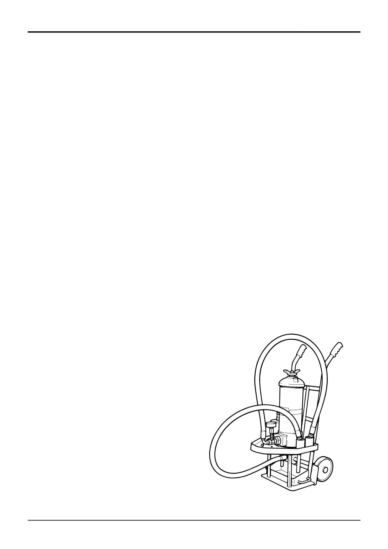
The purpose of cleaning oil is to remove contaminants of all
types and sludge by filtering hydraulic fluid through a
cleaning unit, as illustrated or similar. General Bulletin 011
also refers.
Procedure
Connect the cleaning unit in place of the hydraulic filter and
run the system for sufficient time to pump all the hydraulic
fluid through the unit. Disconnect the cleaning unit and
reconnect the filter. Top up the system with clean hydraulic
fluid as required.
S168050
9803/3280
Issue 1
Section E
Hydraulics
Section E
21 - 1
Service Procedures
21 - 1
A
B
D
A
B
C
A396190
A
9803/3280
Issue 1
Section E
Hydraulics
Section E
21 - 2
Service Procedures
21 - 2
Fixed Flow Pumps
Fitting
1
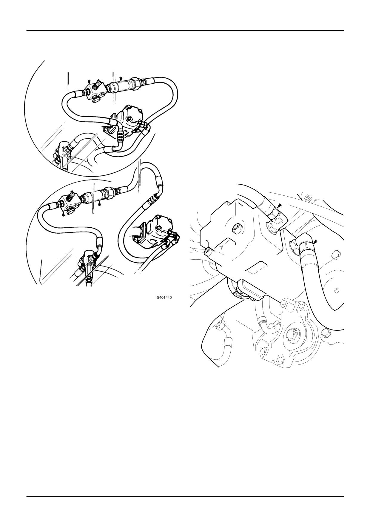
a Pump section 1 - disconnect hose C from the
Flow and Pressure Testing
pump. Fit the flow meter and load valve (see Note
2) between hose C and the pump.
Before removing the pump it is necessary to determine the
source of any problem by measuring the output flow at
b Pump section 2 - disconnect hose D from the
system pressure from both of the pump outlet ports.
pump. Fit the flow meter and load valve (see Note
2) between hose D and the pump.
To check flow it is necessary to fit flow meter A into the
output line of each pump section in turn. If available, load
Note 2: Make sure the load valve is in the open position, i.e.
valve B (service tool 892/00270) should also be installed (see
with the adjusting knob screwed fully out, before carrying
Note 1). Make sure the flow meter is installed with its arrow
out the Checking Flow procedure.
pointing away from the pump and, if applicable, located
between the pump and the load valve.
Removing
Removing is the reverse of fitting.
Note 1: If no load valve is available, ignore the references to
the load valve in Fitting/Removing a Flow Meter and Load
Checking Flow
Valve below. An alternative method of determining flow is
included in the Checking Flow procedures following.
1
Check the setting of the Main Relief Valve (MRV) as
described in Loader Valve, Pressure Testing. Adjust if
Fitting/Removing a Flow Meter and Load
necessary.
Valve
2
a Using a load valve - fit a flow meter and load valve,
Before fitting/removing a flow meter and load valve, switch
as described in Fitting, to each pump outlet in turn.
off the machine and operate the loader/excavator controls a
Fit a 0-400 bar (0-6000 lbf/in2) pressure gauge to
few times to vent system pressure.
the load valve pressure test connector.
! WARNING
b If no load valve is available - fit a flow meter, as
described in Fitting, to each pump output in turn.
Hydraulic fluid at system pressure can injure you. Before
disconnecting or connecting hydraulic hoses, stop the
3
Start the engine and bring the hydraulics up to working
engine and operate the controls to release pressure
temperature 50ºC (122ºF). Set the engine speed to
trapped in the hoses. Make sure the engine cannot be
2200 rpm.
started while the hoses are open.
INT-3-1-11/1
4
a Using a load valve - adjust the load valve so that
the pressure gauge reading is just below the MRV
! WARNING
setting.
Take care when disconnecting hydraulic hoses and
fittings as the oil will be HOT.
TRANS 1-2
b If no load valve is available - raise or lower the
loader arms until the rams are fully open or closed.
Continue to operate the raise/lower control so that
system pressure builds up. Watch the flow meter
and note its reading at the moment the MRV
operates.
5
The flow reading should be as listed in Technical
Data.
9803/3280
Issue 1
Section E
Hydraulics
Section E
22 - 1
Service Procedures
22 - 1
Variable Flow Pumps
Flow and Pressure Testing
D
C
A
B
S315770
9803/3280
Issue 1
Section E
Hydraulics
Section E
22 - 2
Service Procedures
22 - 2
Variable Flow Pumps
Flow and Pressure Testing
Load Sensing Pressure
Stand-by Pressure
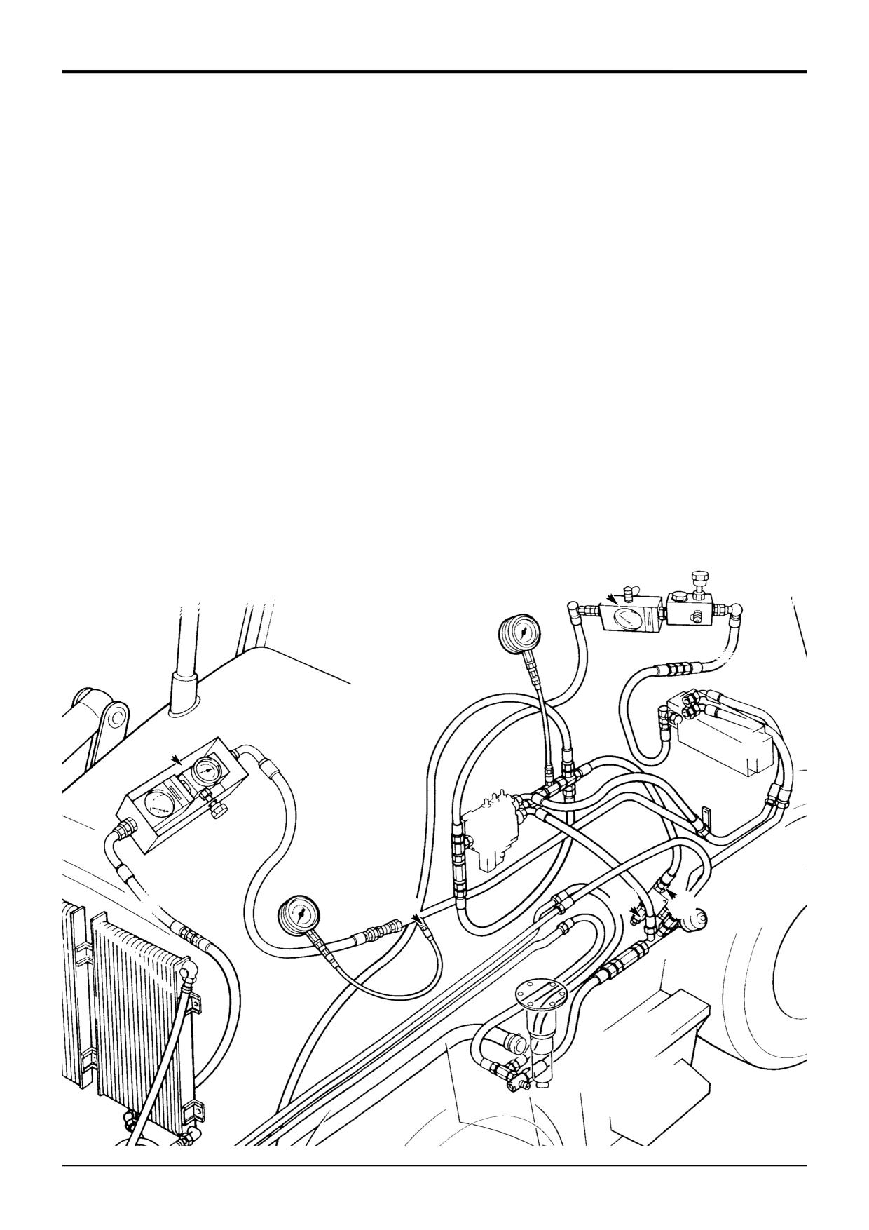
With no services operating, there should be no pressure in
With the engine switched off, the pump swashplate is spring
the load sense line, this is because hydraulic oil flows
loaded to the full flow position. On engine start up standby
through the load sense circuit back to the hydraulic tank. If a
pressure moves the swash plate to minimum flow position
shuttle valve is ‘stuck’, or a hose kinked, then a pressure
(see descriptions). To check stand-by pressure:
could be induced in the load sense lines, this will have an
effect on the hydraulic system. To check load sense
1
Warm the hydraulic oil to working temperature, i.e.
pressure:
50°C (122°F):
1
Warm the hydraulic oil to working temperature, i.e. 50°C
a Set the engine speed to 2200 rev/min.
(122°F):
b Operate the loader shovel dump service to blow off
a Set the engine speed to 2200 rev/min.
the auxiliary relief valve.
b Operate the loader shovel dump service to blow off
2
Lower the backhoe bucket and loader shovel to rest on
the auxiliary relief valve.
the ground; stop the engine; operate the control levers
to vent residual hydraulic pressure.
2
Lower the backhoe bucket and loader shovel to rest on
the ground; stop the engine; operate the control levers
3
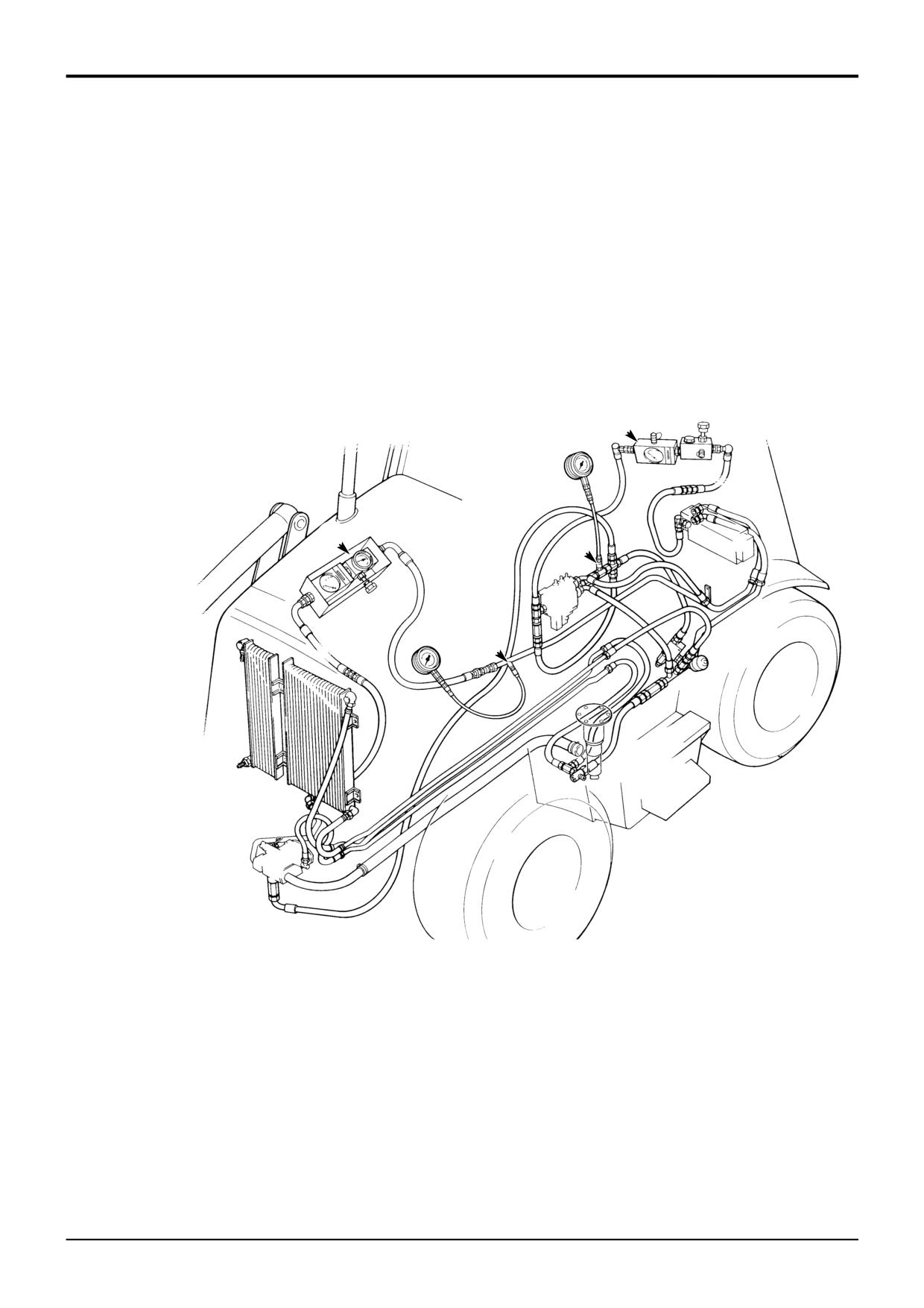
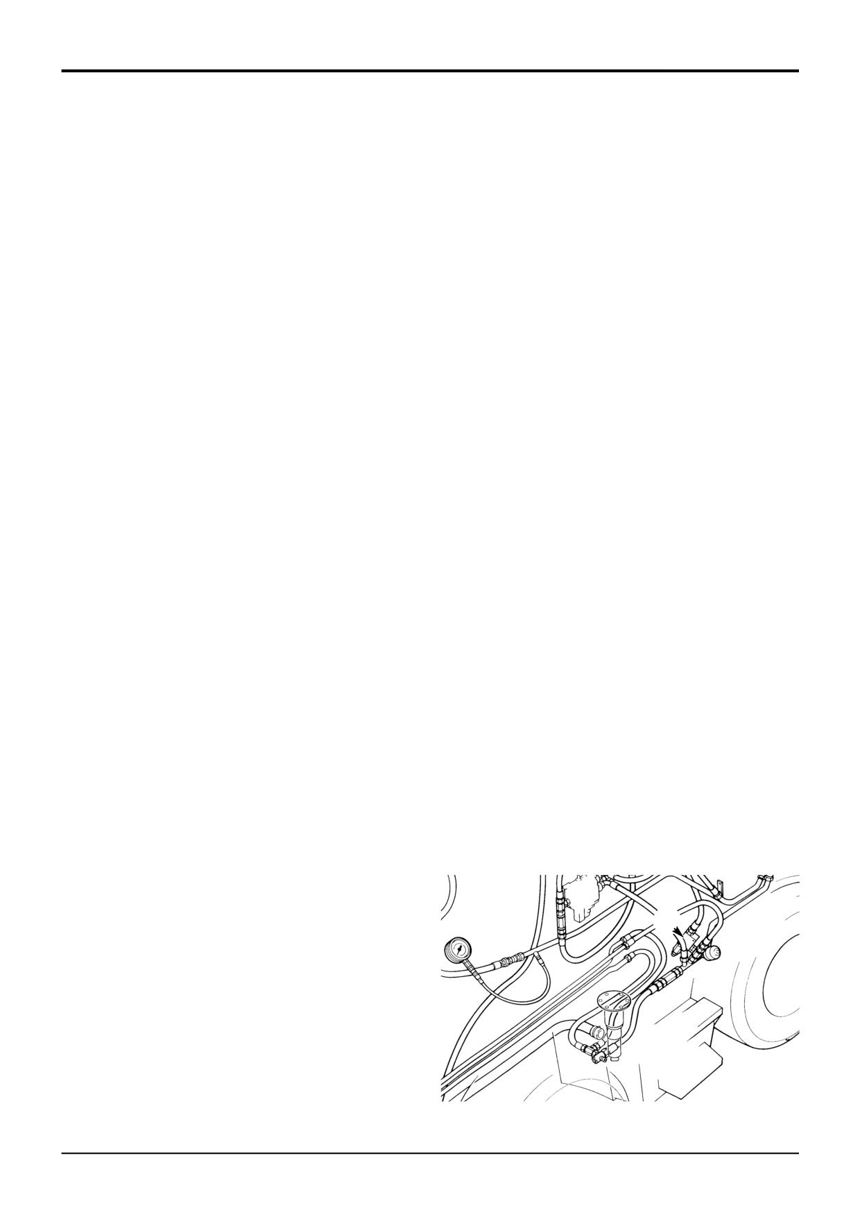
Connect a 0 - 400 bar (0 - 6000 lbf/in2) pressure gauge
to vent residual hydraulic pressure.
to pressure test connector B located on the pump
pressure out line.
3
Connect a 0 - 400 bar (0 - 6000 lbf/in2) pressure gauge
to pressure test connector A located on the load sense
4
Start the engine and run at 2200 rev/min.
line from the loader valve.
5
Do not move the steering wheel and make sure that all
4
Start the engine and run at 2200 rev/min.
control levers remain in ‘neutral’ position.
5
Do not move the steering wheel and make sure that all
6
Check the pressure gauge reading, which should be as
control levers remain in ‘neutral’ position.
specified in Technical Data.
6
Check the pressure gauge reading, which should be as
7
If the pressure is not as specified, do not make any
specified in Technical Data.
adjustments at this stage. Complete the other checks
detailed in this section.
7
If the pressure is higher than specified, first move the
steering wheel and then any of the service levers. If this
8
Refer to Regulator Valve Adjustment.
does not reduce the pressure, physically check the load
sense lines for trapping or kinking. As a last resort, the
service valves may have to be removed and checked for
sticking shuttle valves. However, this should not be
done until all other checks have been completed.
8
Machines with the load sense pressure relief valve
adjust the load sense pressure relief valve E. Machines
without a load sense pressure relief valve adjust the
regulator valve.
E
S315770
9803/3280
Issue 1
Section E
Hydraulics
Section E
22 - 3
Service Procedures
22 - 3
Variable Flow Pumps
Flow and Pressure Testing (Cont’d)
3
Connect a 0 - 400 bar (0 - 6000 lbf/in2) pressure gauge
Maximum Hydraulic Stall
to pressure test connector B located on the pump
pressure out line.
With variable flow hydraulics the pump swashplate angle will
increase or decrease according to pressure demand.
4
Start the engine and run at 2200 rev/min.
However in situations of maximum hydraulic stall, i.e. ram full
travel, the pressure in the circuit will achieve the setting of
5
Raise the loader arms to achieve full travel, hold the
the pressure regulator spool. To check the setting:
arms in this position and note the gauge reading, which
should be as specified in Technical Data.
Note: Machines with a load sense relief valve, disconnect
and blank the load sense relief valve E at F.
6
If the pressure is higher than specified, the pressure
compensator spool may be set incorrectly or the
1
Warm the hydraulic oil to working temperature, i.e. 50°C
swashplate may not be moving.
(122°F):
If the pump pressure is lower than specified, the flow
a Set the engine speed to 2200 rev/min.
spool may be set incorrectly, or there may be a leak in
the load sense line.
b Operate the loader shovel dump service to blow off
the auxiliary relief valve.
Do not make any adjustments at this stage. Complete
the other checks detailed in this section.
2
Lower the backhoe bucket and loader shovel to rest on
the ground; stop the engine; operate the control levers
7
Refer to Regulator Valve Adjustment.
to vent residual hydraulic pressure.
D
C
B
E F
S315770
9803/3280
Issue 1
Section E
Hydraulics
Section E
22 - 4
Service Procedures
22 - 4
Variable Flow Pumps
Flow and Pressure Testing (Cont’d)
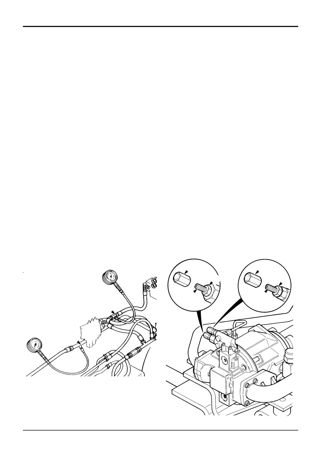
Pump Flow
Load Sense Line Flow
It is not possible to test full pump flow at system pressure
The load sense line communicates the load pressure
whilst the pump is installed on the machine. This is because
required at a service to the pump. If there is a blockage or
the pump swashplate angle will return to minimum angle
leak in the line, the hydraulic system will not operate
(zero flow) when the system reaches full pressure (see
effectively.
descriptions).
Load sensing is a ‘dynamic flow’ type. That is, there is a
However, it is possible to test the pump flow whilst ‘blowing
constant flow of oil from the pump to the shuttle valves.
off’ an auxiliary relief valve which is set lower than system
When a pressure signal is felt at the service port, the flow is
pressure. In the example below, the shovel head side A.R.V.
interrupted and the pump immediately responds to the
is used. The readings taken in this test give a ‘snapshot’ of
demand. (Unlike a ‘static’ system where the pressure signal
pump performance and can be used to establish if major
must move from the valve block, back up the load sense
pump maintenance is required.
line to the pump).
1
Warm the hydraulic oil to working temperature, i.e. 50°C
1
Warm the hydraulic oil to working temperature, i.e.
(122°F):
50°C (122°F):
a Set the engine speed to 2200 rev/min.
a Set the engine speed to 2200 rev/min.
b Operate the loader shovel dump service to blow off
b Operate the loader shovel dump service to blow off
the auxiliary relief valve.
the auxiliary relief valve.
2
Lower the backhoe bucket and loader shovel to rest on
2
Lower the backhoe bucket and loader shovel to rest on
the ground; stop the engine; operate the control levers
the ground; stop the engine; operate the control levers
to vent residual hydraulic pressure.
to vent residual hydraulic pressure.
3
Connect a 0 - 400 bar (0 - 6000 lbf/in2) pressure gauge
3
Connect a flowmeter into the load sense line, a good
to pressure test connector B located on the pump
access point is where the LS line enters the backhoe
pressure out line.
valve as shown at D.
4
Connect a flowmeter to the pump pressure out line as
5
Start the engine and run at 2200 rev/min. Check the
shown at C.
flow which should be as specified in Technical Data.
5
Start the engine and run at 2200 rev/min.
6
If a service is selected, the flow should drop to zero
(but the pressure will increase).
6
Raise the loader arms and fully dump the loader shovel.
7
If there is no flow in the system, then check the load
7
Hold the shovel in the dump position (to blow off the
sense lines for being trapped or kinked, also move the
A.R.V.) and check the flow and pressure gauge
service control levers and the steering wheel.
readings, which should be as specified in Technical
Data.
If there is still no flow, then there is the possibility of a
shuttle valve being stuck. Do not dismantle valves at
8
If the pump flow is not as indicated, do not make any
this stage but complete all other tests listed in this
adjustments at this stage. Complete the other checks
section.
detailed in this section.
9
Refer to Regulator Valve Adjustment.
9803/3280
Issue 1
Section E
Hydraulics
Section E
22 - 5
Service Procedures
22 - 5
Variable Flow Pumps
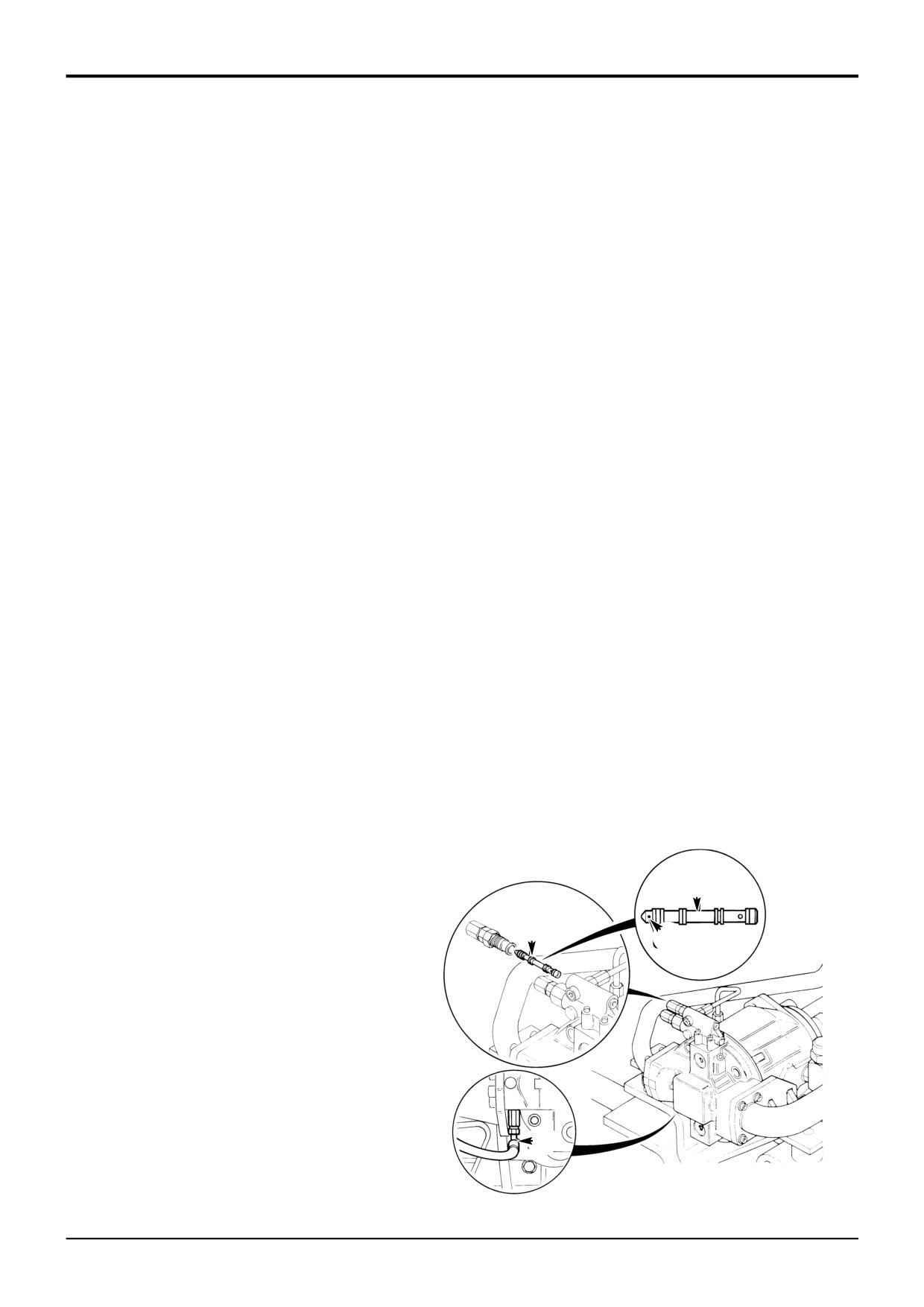
Regulator Valve Adjustment
Note: If a new regulator valve is fitted, or a valve stripped,
cleaned and rebuilt, then the pressure spool should be
backed off to a low pressure. This will prevent inadvertent
damage to the pump.
Flow Regulator Spool
Pressure Regulator Spool
The pressure in the pump out line (pressure test connector
As previously explained, there is no ‘main relief valve’ to
B) should be 20 bar (290 lbf/in2) greater than the pressure in
control the system pressure (the pump swashplate angle will
the load sense line (pressure test connector A). If not adjust
increase or decrease according to pressure demand).
the regulator flow spool as described below:
However in situations of maximum hydraulic stall, i.e. ram full
travel, the pressure in the circuit will achieve the setting of
1
Lower the backhoe bucket and loader shovel to rest on
the pressure regulator spool. To adjust the setting:
the ground; stop the engine; operate the control levers
to vent residual hydraulic pressure.
1
Lower the backhoe bucket and loader shovel to rest on
the ground; stop the engine; operate the control levers
2
Gain access to the regulator valve assembly (mounted
to vent residual hydraulic pressure.
on the pump).
2
Gain access to the regulator valve assembly (mounted
3
Remove cap C and loosen locknut D.
on the pump).
4
Turn adjusting screw E clockwise to increase pressure
3
Remove cap F and loosen locknut G.
setting and anti-clockwise to decrease setting.
4
Turn adjusting screw H clockwise to increase pressure
5
Repeat pressure test as detailed previously and
setting and anti-clockwise to decrease setting.
establish valve is set correctly.
5
Repeat pressure test as detailed previously and
6
Tighten locknut, refit cap.
establish valve is set correctly.
6
Tighten locknut, refit cap.
F
C
G
D
H
E
A
B
S273401
S273100
9803/3280
Issue 1
Section E
Hydraulics
Section E
22 - 6
Service Procedures
22 - 6
Variable Flow Pumps
Regulator Valve Adjustment (Cont’d)
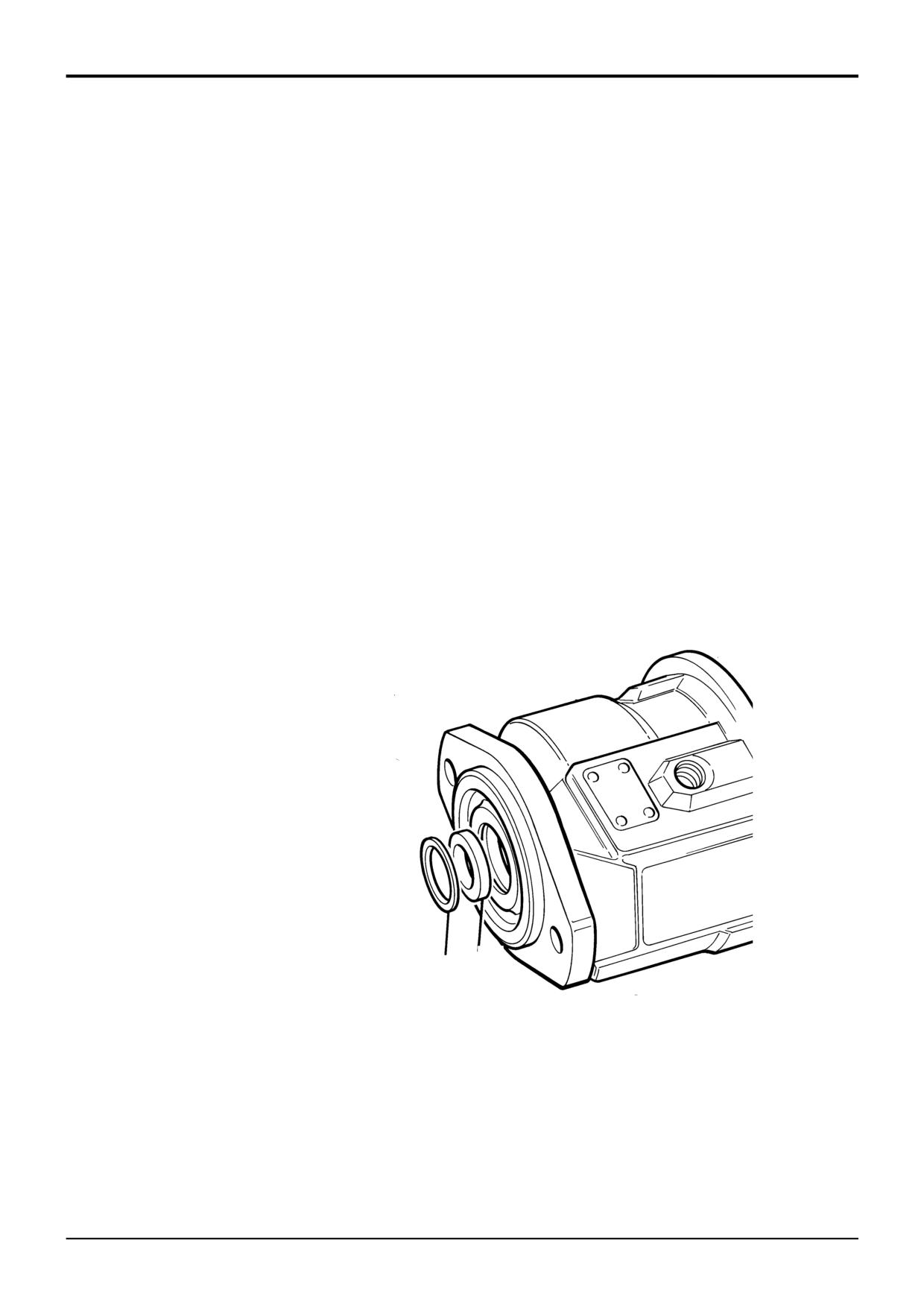
The load sense system is a dynamic type, which means a
small flow (0.22 to 1.1 gall/1 to 5 litre per minute) is
circulated through the load sense line.
The flow is available due to a 0.02 in (0.6 mm) orifice in the
flow regulator spool in the pump control housing. This orifice
can be blocked or partially restricted which will give poor
performance, slow operating speed and/or low maximum
stall speed. If completely blocked, margin pressure and
stand-by pressure can be difficult to adjust and the loader
services may operate intermittently even though the
excavator operates correctly.
If any of the above symptoms are experienced carry out the
following:
1
Lower the backhoe bucket and loader shovel to rest
on the ground. Stop the engine and remove the
starter key.
2
Gain access to the regulator valve assembly.
3
Disconnect the load sense line at A. Attach a 0.25
inch (6.35 mm) hose to pump of suitable length to
route to a measuring container.
4
Start the engine and measure the flow which should
be at least 0.22 gall/1 litre per minute at 2200 RPM.
5
If the flow is below 0.22gall/1 litre per minute, remove
spool B and clean/unblock orifice C as required.
6
Fit spool B and check the flow as described at step 3
and 4.
7
If the flow is within limits check the stand-by pressure.
Refer to Flow and Pressure Testing.
B
B
C
A
347850
9803/3280
Issue 1
Section E
Hydraulics
Section E
22 - 7
Service Procedures
22 - 7
Variable Flow Pumps
Renewing Drive Shaft Seal
Note: The following procedure describes renewal of the
shaft seal. However this is not the normal sequence, the
sealing ring would normally be assembled with the taper
roller bearing from inside the pump to ensure a secure
sealing condition. If the shaft seal is to be renewed in this
manner, it is extremely important not to scratch or damage
the shaft, otherwise leakage will occur.
1
Remove retaining ring 1 and use a special rounded tool
such as a ground screwdriver to remove the drive shaft
sealing ring 2.
2
Examine the seal running area (driveshaft and housing)
for wear or damage. Damage in these areas will require
the pump to be further dismantled.
3
Lubricate the new seal with JCB Special MPL Moly
Grease.
4
Install the new seal, it is advisable to use a tube or
similar located over the driveshaft to ensure the seal
enters the housing evenly. DO NOT push the seal too
far into the housing. If the shaft seal touches the
bearing, the seal will be damaged.
5
Assemble the retaining ring 1.
2
1
S271880
9803/3280
Issue 1
Section E
Hydraulics
Section E
22 - 8
Service Procedures
22 - 8
Variable Flow Pumps
Shuttle Valve Signal Network - Testing
The shuttle network can be easily checked. Start the engine
and operate the hydraulic system until the oil is at working
temperature.
With the engine at 1500 revs/min operate each service in the
following order:
1
Bucket
2
Dipper
3
Right Stabiliser
4
Left Stabiliser
5
Boom
6
Slew
7
Extradig
8
Lift
9
Shovel
10 Auxiliary
11 Steering
Note: If your machine is not equipped with these valve
sections, start with the furthest section from the pump and
work back to the nearest section.
If one valve section function either fails to work or is slow to
work in either one or both directions, the primary shuttle in
that section may be at fault.
If two or more valve sections next to each other fail to
operate correctly, check the secondary shuttles. To check
the secondary shuttle operate each service in sequence, the
last correctly functioning service nearest the pump may have
a secondary shuttle in that section at fault.
When a shuttle is suspected of malfunctioning, do the
following check:
Stall any control valve that is near the pump than the
suspected control valve. This should stall the entire system.
While at stall operate the malfunctioning valve section, if the
section operates correctly the shuttle in question is at fault.
If section still malfunctions the shuttle is NOT at fault.
Shuttles may be removed, check the seals and the shuttle
ball. Clean and refit or fit a new shuttle as required.
9803/3280
Issue 1
Section E
Hydraulics
Section E
23 - 1
Service Procedures
23 - 1
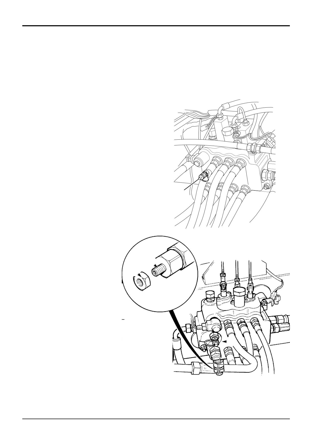
Loader Valve - Pressure Testing
Main Relief Valve (M.R.V.)
Make sure that the hydraulic oil is at working temperature,
i.e. 50°C (122°F).
Lower the backhoe bucket and loader shovel to rest on the
ground; stop the engine; operate the control levers to vent
residual hydraulic pressure.
1
Connect a 0 - 400 bar (0 - 6000 lbf/in2) pressure gauge
to pressure test connector A on the loader valve, (refer
to Service Tools).
2
With the engine running at 1500 revs/min, check M.R.V.
pressure by raising or lowering the loader arms until the
rams are fully open or closed and noting the maximum
gauge reading. CAUTION: Do not select 'float'. The
maximum pressure should be as stated in Technical
Data.
Note: The rams must be 'held' open or closed when reading
gauge.
A
3
If the pressure is incorrect, loosen locknut D and adjust
screw C. Turn it clockwise to increase pressure and
anti-clockwise to decrease the pressure. When the
pressure is correct, tighten the locknut and check the
352710
pressure again. Adjust as required.
C
D
A
S266281
9803/3280
Issue 1
Section E
Hydraulics
Section E
23 - 2
Service Procedures
23 - 2
Loader Valve - Pressure Testing
Unloader Valve
Make sure that the hydraulic oil is at working temperature,
i.e. 50°C (122°F).
Lower the backhoe bucket and loader shovel to rest on the
ground; stop the engine; operate the control levers to vent
residual hydraulic pressure.
Make sure that the ‘hydraulic speed control’ and ‘smooth
ride system’ facilities are NOT switched on, otherwise the
correct unloader valve pressure cannot be obtained.
If the machine has a front-mounted roadbreaker, ensure that
the roadbreaker control valve lever is in the 'off' position
(lever down), otherwise the roadbreaker relief valve will
operate and prevent unloader valve pressure from being
reached.
1
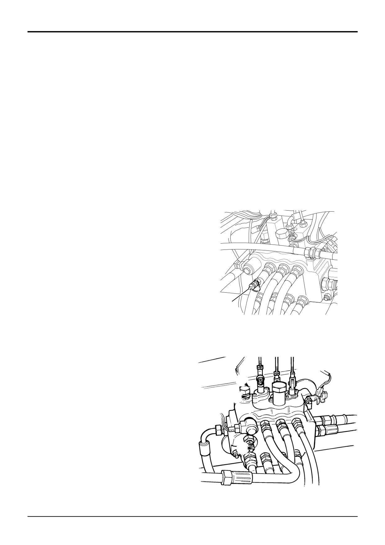
Connect a 0 - 400 bar (0 - 6000 lbf/in2) pressure gauge
to pressure test connector A.
2
With the engine running at 1500 revs/min, slowly
operate arms raise or lower.
Note 1: The arms raise or lower service is specified because
it has no auxiliary relief valve (A.R.V.). Selecting this service
ensures that the pressure vents through the M.R.V. and not
an A.R.V.
3
When the service reaches full travel, return the lever to
the neutral position. Select the service again, very
slowly, the pressure gauge will rise until a step/kick is
A
352710
seen in the rate of change in the pressure increase. This
is the start of unloader operation. Keep selecting the
service until a sudden sharp increase in pressure is
observed with a change of engine sound, this point is
the unloader setting and should be as specified in
Technical Data.
4
If the pressure is incorrect, slacken locknut E and
adjust cap F. Turn it clockwise to increase pressure and
anti-clockwise to decrease the pressure. When the
pressure is correct, tighten the locknut and check the
F
pressure again. Adjust as required.
If the correct pressure cannot be achieved, add or
E
subtract shims as required, refer to Loader Valve -
Fixed Flow, Dismantling and Assembly - Unloader
Valve.
A
S266300
9803/3280
Issue 1
Section E
Hydraulics
Section E
23 - 3
Service Procedures
23 - 3
Loader Valve - Pressure Testing
Hydraulic Speed Control (HSC)
The following procedure can be used to establish if the
hydraulic speed control facility is working correctly.
Make sure that the hydraulic oil is at working temperature,
i.e. 50°C (122°F).
Lower the backhoe bucket and loader shovel to rest on the
ground; stop the engine; operate the control levers to vent
residual hydraulic pressure.
1
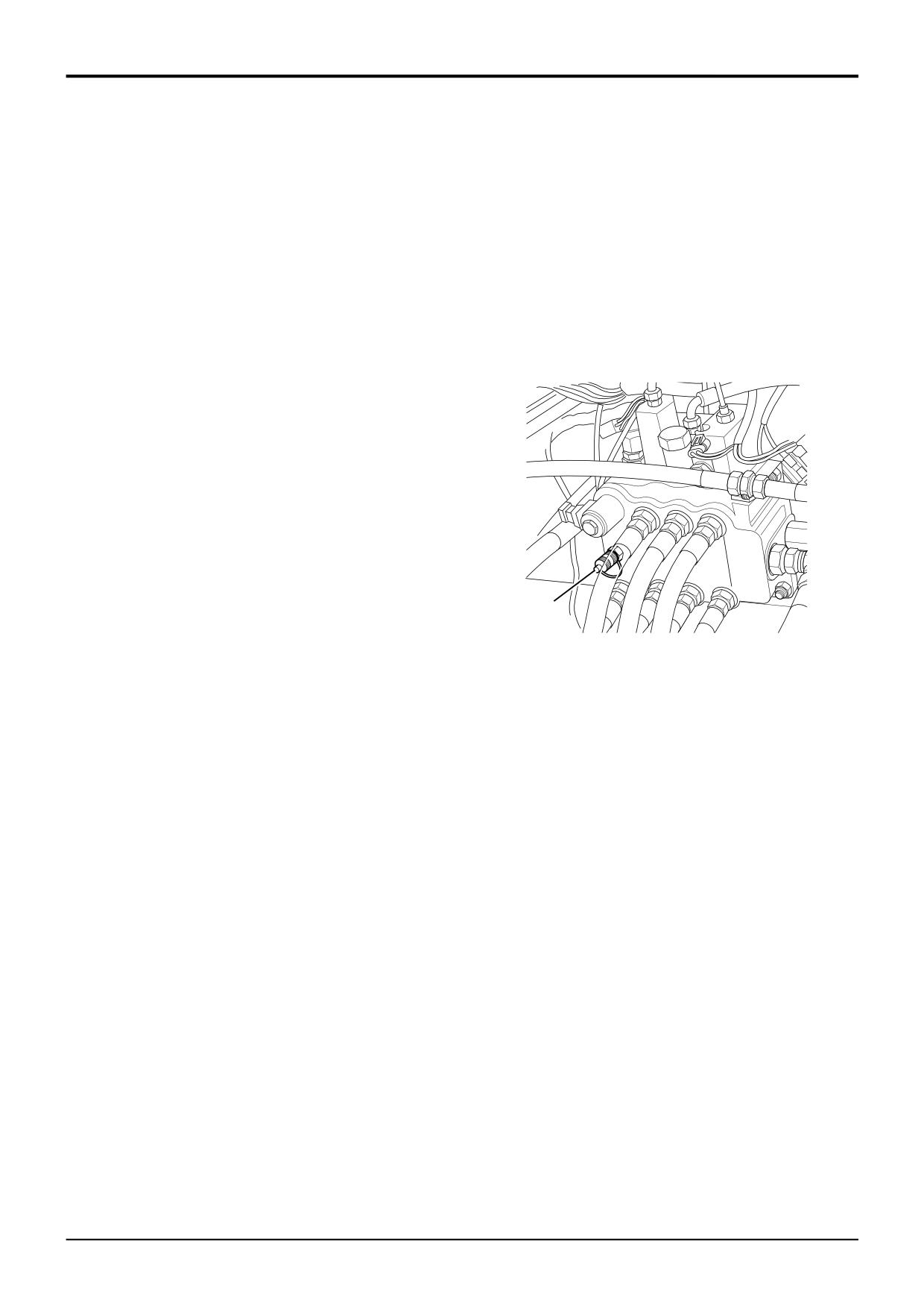
Connect a 0 - 400 bar (0 - 6000 lbf/in2) pressure gauge
to pressure test connector A.
2
With the engine running at 1500 revs/min, slowly
operate arms raise, the pressure should be
approximately 138 bar (2000 lbf/in2).
3
Make sure that the HSC rocker switch (mounted on the
console) is in the OFF position. Raise the arms slowly,
select the rocker switch to ON, the arms should raise
quicker.
4
Make sure that the HSC rocker switch (mounted on the
console) is in the OFF position. Raise the arms slowly,
A
352710
press the button on the loader control knob, the arms
should raise quicker.
5
If the loader arms fail to respond, then check the HSC
hydraulic and electrical circuits for any faults.
9803/3280
Issue 1
Section E
Hydraulics
Section E
23 - 5
Service Procedures
23 - 5
Loader Valve - Pressure Testing
Auxiliary Relief Valves - Using Hand Pump
6
7
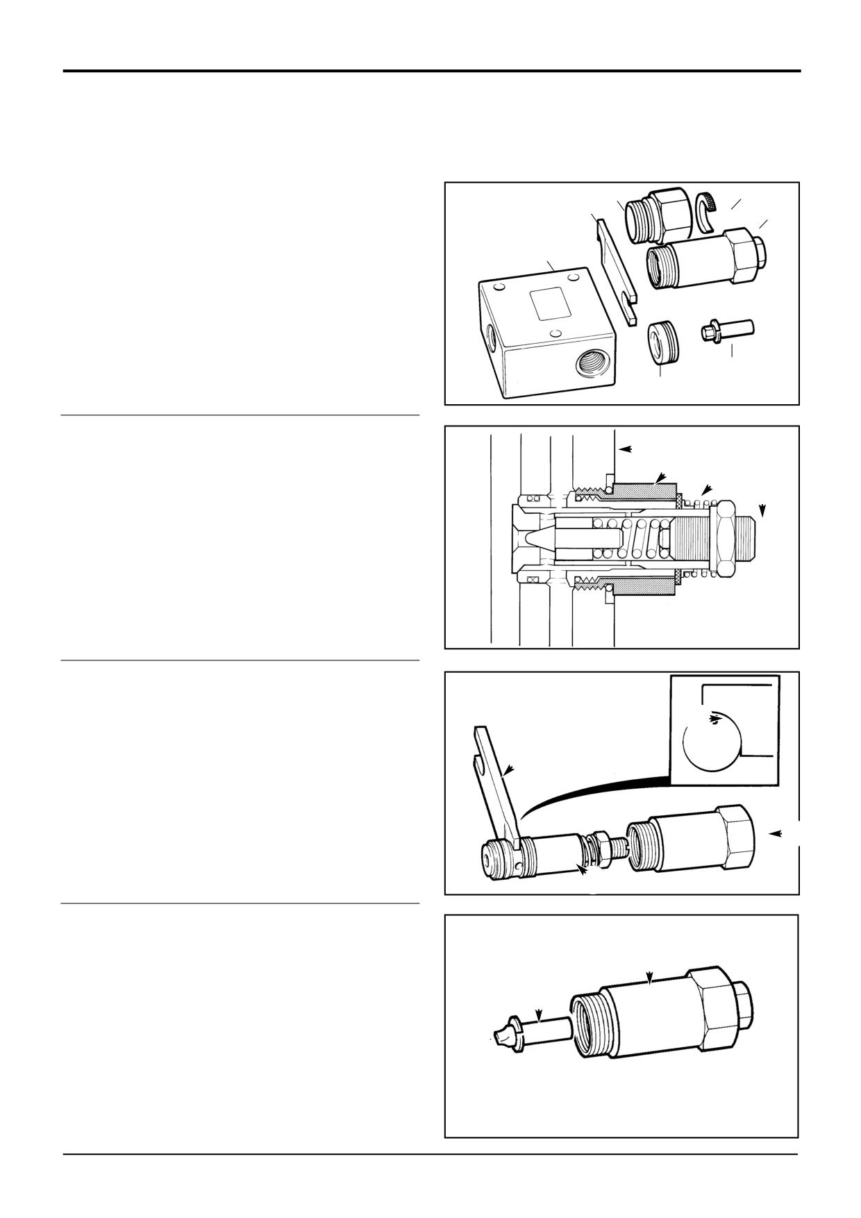
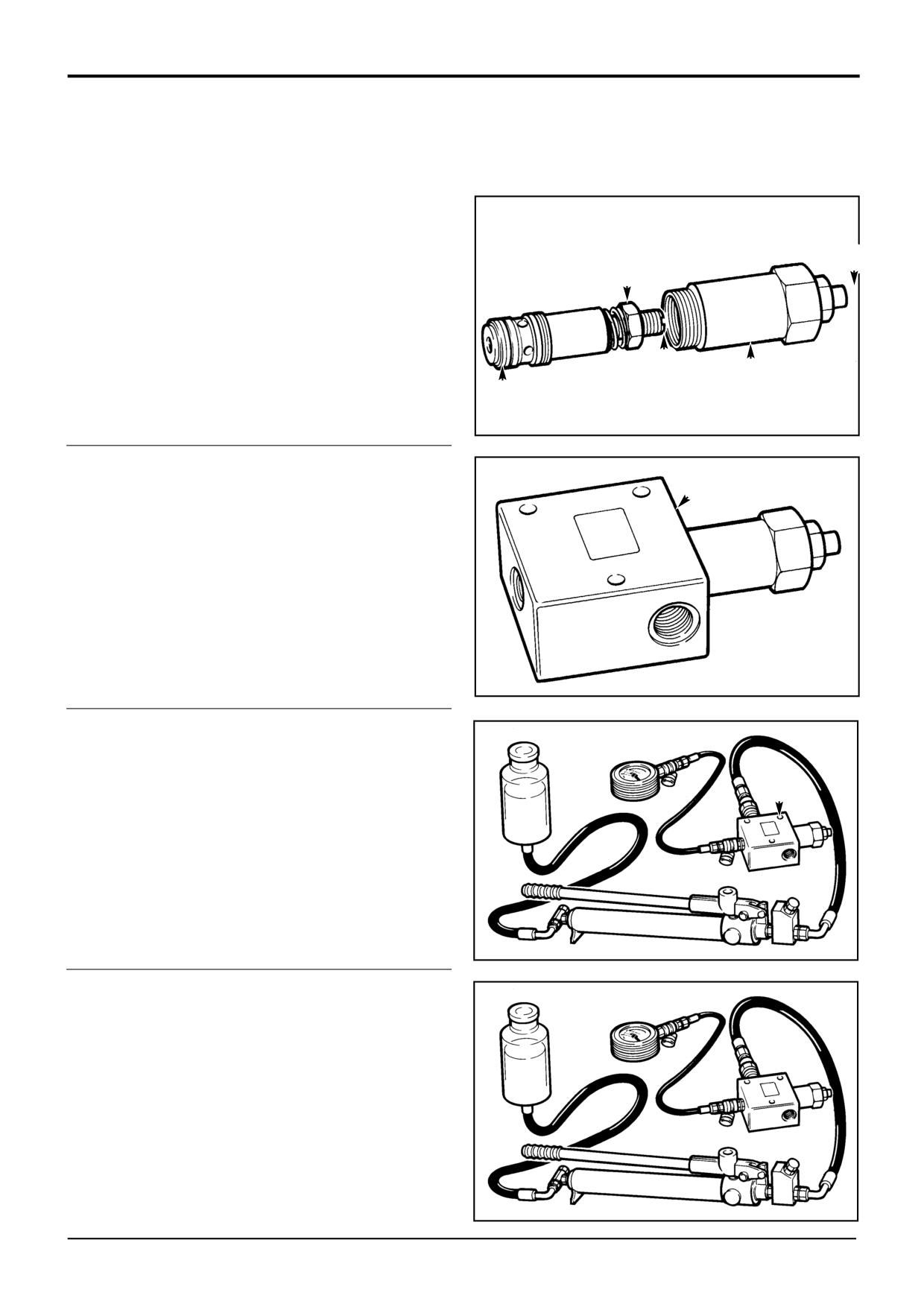
To pressure test and re-set the auxiliary relief valves
4
2
(A.R.V.'s), service kit 892/00309 must be used.
The service kit comprises; a test block 1, a setting body 2
1
with adjusting pin 3, a special spanner 4, anti-cavitation lock
out bung 5. A.R.V. cartridge removal tool 892/00335
comprises; an extractor cap 6 and a 'C' washer 7.
3
5
S196700
1
Remove the complete A.R.V. assembly from the valve
block. If the A.R.V. sub-assembly 7 remains in the valve
E
block, proceed as follows:
!
@
a
Fit extractor cap 11 over the A.R.V. sub-assembly
7
7, into the valve block E.
b
Fit 'C' washer 12 on top of the extractor cap, but
under the anti-cavitation spring seat as shown.
c
Unscrew the extractor cap, - the A.R.V. sub-
assembly will withdraw with the extractor cap.
S162560
2
Use special spanner 4 located in cross holes A and
separate the A.R.V. sub-assembly 7 from its cap 8.
A
4
8
S162570B
7
3
Install adjusting pin 3 into setting body 2.
2
3
S162570C
9803/3280
Issue 1
Section E
Hydraulics
Section E
23 - 6
Service Procedures
23 - 6
Auxiliary Relief Valves - Using Hand Pump
4
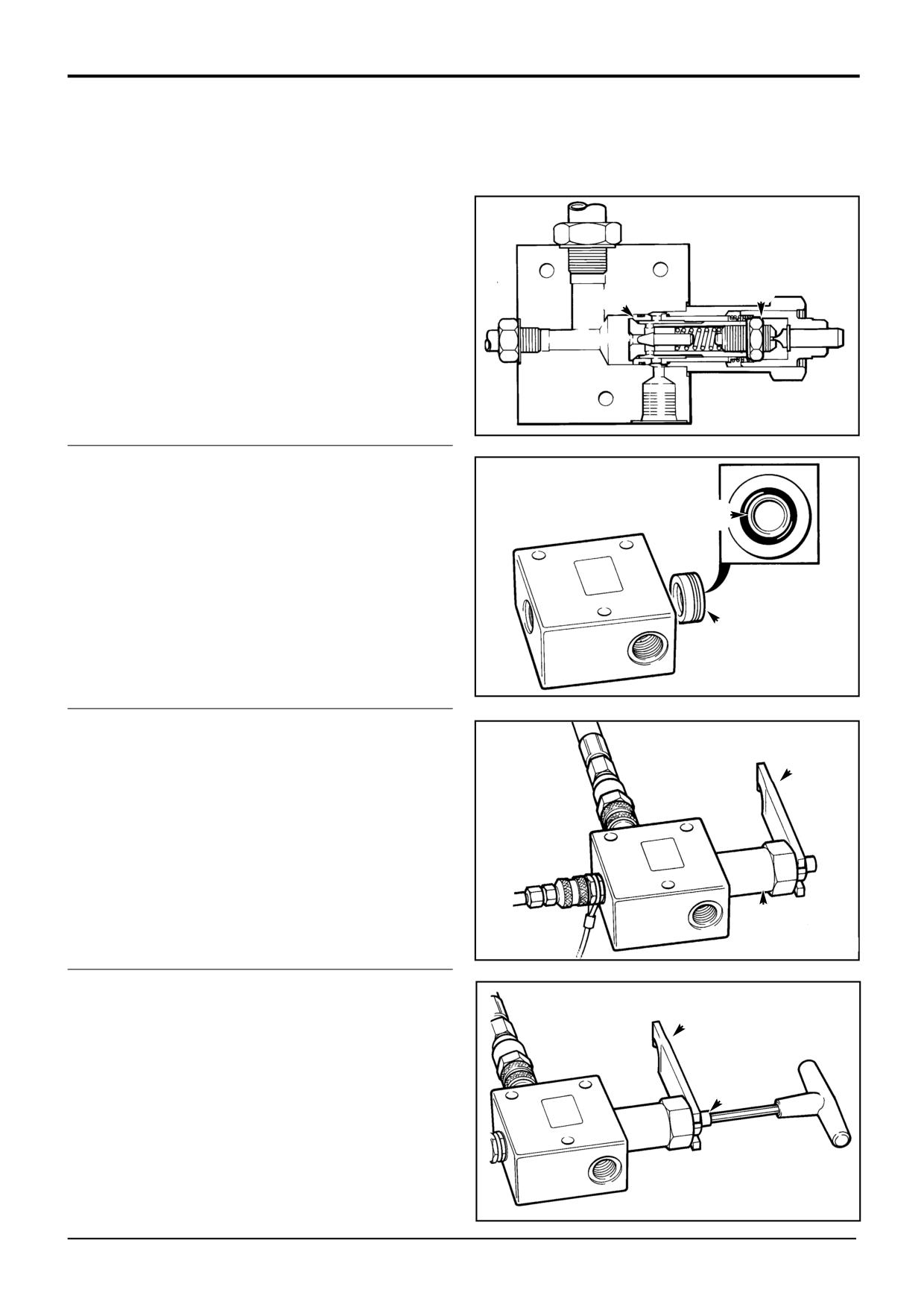
Install the A.R.V. sub-assembly into setting body 2.
Make sure that the adjusting pin 3 correctly locates in
adjusting screw 9.
Make sure that the lock nut 10 correctly locates in the
3
setting body socket - the anti-cavitation cone should
0
still be closed, as shown at B.
9
2
B
S162570D
5
Install the A.R.V. sub-assembly and setting body into
test block 1. Make sure that the assembly is installed in
the port marked 'RV' (relief valve).
1
S162570E
6
Connect a hydraulic hand pump to port 'P' (pump) of
S162570F
the test block 1. Make sure that the hand pump is filled
with JCB Hydraulic fluid.
Connect a 0 to 400 bar (0 to 6000 lbf/in2) pressure test
1
gauge to port 'G' (gauge) of the test block 1.
Port 'T' (tank) can be left open when using a hydraulic
hand pump.
7
Raise the pressure at the valve inlet using the hydraulic
hand pump, when the A.R.V. 'cracks' and oil escapes
S162570F
from the port marked 'T' the pressure gauge will
indicate the A.R.V. setting.
If the A.R.V. setting is correct, move to step 12.
If the A.R.V. setting is not correct, move to step 8.
9803/3280
Issue 1
Section E
Hydraulics
Section E
23 - 7
Service Procedures
23 - 7
Auxiliary Relief Valves - Using Hand Pump
8
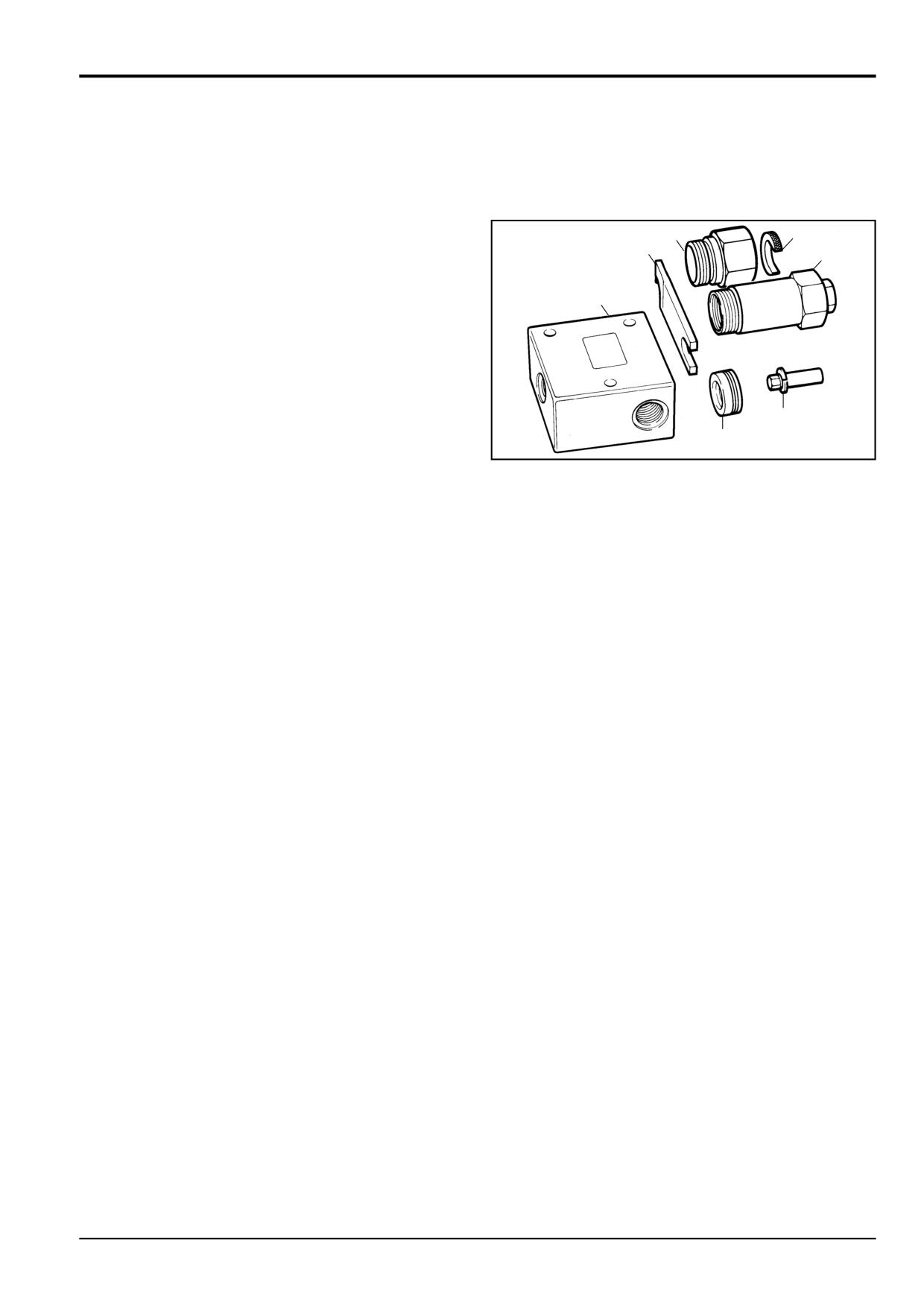
Use the hand pump to raise approximately 172 bar
(2500 lbf/in2) pressure at the valve inlet.
Note: Raising the pressure at the valve inlet locks the anti-
cavitation cone C onto its seat, this allows the A.R.V.
adjusting screw lock nut 10 to be loosened (step 10).
0
C
If the pressure is maintained move to step 10.
If the pressure falls off rapidly, or if no pressure can be
obtained it is possible that the anti-cavitation cone is
not seating effectively, in this instance move to step 9.
S162570G
9
If no pressure can be raised (see step 8) at the valve
inlet, remove the A.R.V. assembly and install anti-
cavitation lock-out bung 6 in the port marked 'RV',
make sure that the bung O-ring face seal D is facing
D
out. Re-fit the A.R.V. assembly.
Note: The anti-cavitation lock-out bung seals and locks the
A.R.V. anti-cavitation function. The bung is only suitable for
the test block application and must NEVER be fitted to the
valve block.
6
The bung can be extracted using a 3/8 - 16 UNC
threaded bolt.
S162570H
10
Release the A.R.V. adjusting screw lock nut (see note):
Engage the nut at the end of setting body 2 using the
4
slot in special spanner 4, turn the nut anti-clockwise to
release the A.R.V. adjusting screw lock nut.
Note: Remember, it will not be possible to release the lock
nut if there is not approximately 172 bar (2500 lbf/in2)
pressure at the valve inlet.
2
S162570J
11
Insert an allen key into adjusting pin 3 (T-Bar type
shown). Push the adjusting pin down and make sure it
has engaged with the A.R.V. adjusting screw.
4
Rotate the T-bar clockwise to increase the pressure
setting and anti-clockwise to decrease the pressure
setting.
3
After adjustment, use the slot in spanner 4 to lock the
A.R.V. adjusting screw lock nut (see note).
Note: Remember, pressure must be maintained at the valve
inlet to ensure the lock nut is tightened.
S162570K
9803/3280
Issue 1
Section E
Hydraulics
Section E
23 - 8
Service Procedures
23 - 8
Auxiliary Relief Valves - Using Hand Pump
12
When the correct A.R.V. setting has been attained,
release the pressure in the test block. Remove the
A.R.V. sub-assembly and its setting body from the test
block.
Separate the A.R.V. sub-assembly from its setting
body.
Install the A.R.V. sub-assembly into its cap.
9803/3280
Issue 1
Section E
Hydraulics
Section E
23 - 9
Service Procedures
23 - 9
Excavator Valve - Pressure Testing
Auxiliary Relief Valves - Using Hand Pump
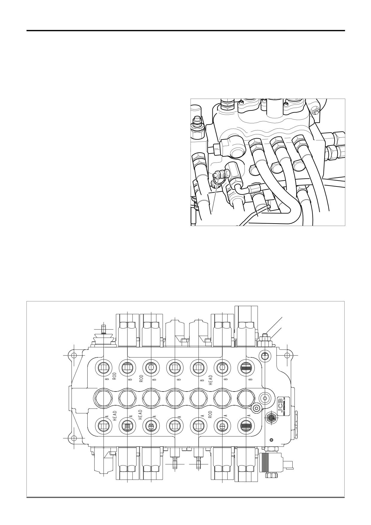
The auxiliary relief valves found in the backhoe valve block
are identical in design to those found in the loader valve
6
7
4
block.
2
Therefore please refer to Loader Valve - Pressure Testing,
1
Auxiliary Relief Valves (ARV’s) for the correct pressure test
procedures.
To pressure test and re-set the auxiliary relief valves
(A.R.V.'s), service kit 892/00309 must be used.
The service kit comprises; a test block 1, a setting body 2
3
with adjusting pin 3, a special spanner 4, anti-cavitation lock
out bung 5. A.R.V. cartridge removal tool 892/00335
5
S196700
comprises; an extractor cap 6 and a 'C' washer 7.
9803/3280
Issue 1
Section E
Hydraulics
Section E
23 - 10
Service Procedures
23 - 10
Excavator Valve - Precision Control (Servo)
(Machines up to serial no. 931159)
*
Pressure Testing
Load Sense Drain Regulator and Relief Valve
Make sure that the hydraulic oil is at working temperature,
i.e. 50°C (122°F).
Lower the backhoe bucket and loader shovel to rest on the
ground; stop the engine; operate the control levers to vent
residual hydraulic pressure.
1
Connect a 0 - 400 bar (0 - 6000 lbf/in2) pressure gauge
to pressure test connector A on the loader valve, (refer
to Service Tools).
2
With the engine running at 1500 revs/min, check that
the M.R.V. pressure is correct, see Loader Valve -
Pressure Testing, Main Relief Valve.
3
With the engine running at 1500 revs/min, operate a
stabiliser service fully and at the same time note the
A
reading in the gauge which should be as stated in
Technical Data.
Note: The ram must be 'held' open or closed when reading
gauge.
4
If the pressure is incorrect, loosen locknut D and adjust
screw C. Turn the screw C clockwise to increase
pressure and anti-clockwise to decrease the pressure.
When the pressure is correct, tighten the locknut and
check the pressure again. Adjust as required.
C
D
A402500
9803/3280
Issue 2*
Section E
Hydraulics
Section E
23 - 11
Service Procedures
23 - 11
Excavator Valve - Precision Control (Servo)
(Machines from January 2003)
Pressure Testing
Load Sense Relief Valve
TBA
9803/3280
Issue 1
Section E
Hydraulics
Section E
23 - 12
Service Procedures
23 - 12
Excavator Valve - Precision Control (Servo)
Pressure Compensator Network - Testing
The pressure compensator valve network can be easily
checked as follows:
1
Start the engine and operate the hydraulic system until
the oil is at working temperature.
2
With the engine at 1500 revs/min operate each service
in turn starting with the service furthest from the pump
inlet section.
If one control valve section function either fails to work
or is slow to work in either one or both directions, the
pressure compensator valve in that section may be at
fault.
When a pressure compensator valve is suspected of
malfunctioning, do the following check:
3
Stall any control valve that is nearer the pump inlet
section than the suspected control valve section. This
should stall the entire system. While at stall operate the
malfunctioning valve section, if the section operates
correctly the pressure compensator valve in question is
at fault.
If the section still malfunctions the pressure
compensator valve is NOT at fault.
Note: The pressure compensator valves may be removed for
inspection, refer to Excavator Valve - Dismantling and
Assembly. Clean and refit, or fit a new pressure
compensator valve as required.
9803/3280
Issue 1
Section E
Hydraulics
Section E
24 - 1
Service Procedures
24 - 1
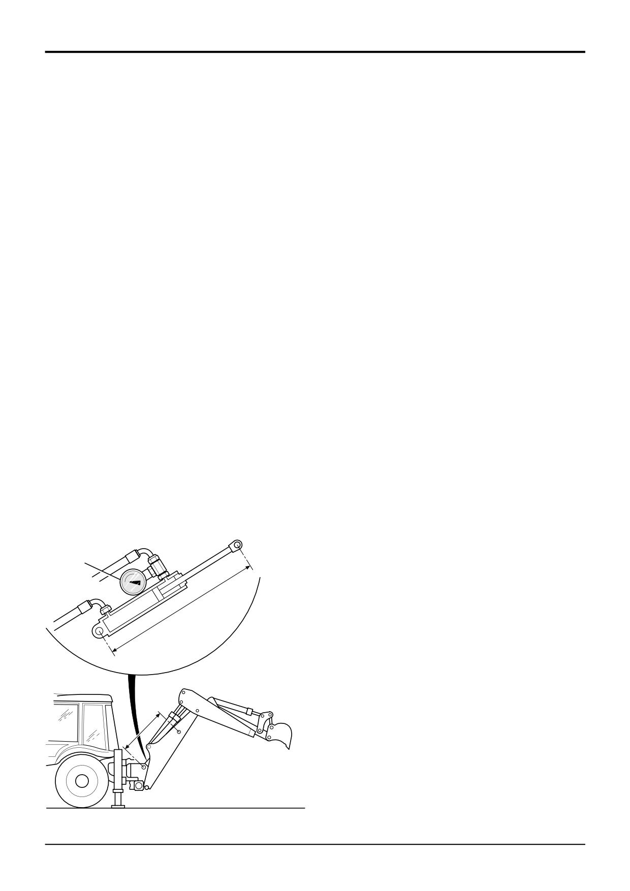
Ram Creep Tests - All Services
If ram creep is suspected the following procedures must be
3
Operate the rams to ensure they are full of hot oil.
carried out to define if the leakage is within tolerance. Ram
creep can be caused by a number of reasons:
4
Apply a load to the suspect ram for example the boom
Cylinder/Piston Leakage, Spool Leakage, ARV Leakage.
ram by raising the dipper to the horizontal as at B.
The text and illustrations show a typical ram installation (in
5
Measure the actual piston rod movement over 10
this instance the boom ram), the principle applies to all
minutes. Measure the movement by checking the pivot
rams.
pin to pivot pin dimensions as at C. Alternatively mark
the rod with a felt tip pen 150mm (5.9 in) from the end
Note: The procedures are not applicable for rams fitted with
cap and check the movement after 10 minutes, this is
hose burst protection valves.
not possible on the majority of boom/extending dipper
rams.
! WARNING
Hydraulic fluid at system pressure can injure you. Before
6
Using Table 1, check if the piston rod movement is within
disconnecting or connecting hydraulic hoses, stop the
the recommended tolerance. If so, the ram creep is
engine and operate the controls to release pressure
acceptable.
trapped in the hoses. Make sure the engine cannot be
started while the hoses are open.
Note: The table indicates the MAXIMUM permitted ram
INT-3-1-11/1
movement.
! WARNING
7
If the rate of movement is unacceptable, identify if the
Take care when disconnecting hydraulic hoses and
fault is as a result of cylinder/piston leakage or spool
fittings as the oil will be HOT.
leakage at the control valve, see procedure B and C.
TRANS 1-2
A Test for Ram Creep
1
Operate the machine to bring the hydraulic oil to a
normal working temperature of 50°C (122°F) which can
be measured using a hydraulic oil temperature probe
(service tool 892/00285).
2
Fit an appropriate pressure gauge A to a tee-piece in the
service hose which is pressurised when the ram in
question is supported (Fig 1).
A
C
B
C
FIG 1
380190
9803/3280
Issue 1