JCB 3CX, 4CX, 214e, 214, 215, 217 & VARIANTS Backhoe Loader. Service Manual - page 19
Section E
Hydraulics
Section E
60 - 4
Excavator Valve
60 - 4
Removal and Replacement
Variable Flow
A
B
C
C
C
S278930
9803/3280
Issue 1
Section E
Hydraulics
Section E
60 - 5
Excavator Valve
60 - 5
Removal and Replacement
Inspection
Variable Flow
Inspect the resilient mounts for damage, cracking etc. If the
! WARNING
mounts are suspect, then replace them with new ones.
Make the machine safe before working underneath it.
Park the machine on level ground, lower the arms. Apply
Replacement
the parking brake, put the transmission in neutral and
stop the engine. Chock both sides of all four wheels.
Replacement is a reversal of the removal sequence.
Disconnect the battery, to prevent the engine being
Hoses and pipes (when applicable) must be re-connected
started while you are beneath the machine.
GEN-1-2
and phased in same position as removal. Refer to
Dismantling and Assembly, Hoses and Pipes.
! DANGER
Hydraulic Pressure
! WARNING
Hydraulic fluid at system pressure can injure you. Before
Fine jets of hydraulic fluid at high pressure can penetrate
disconnecting or connecting hydraulic hoses, stop the
the skin. Do not use your fingers to check for hydraulic
engine and operate the controls to release pressure
fluid leaks. Do not put your face close to suspected
trapped in the hoses. Make sure the engine cannot be
leaks. Hold a piece of cardboard close to suspected
started while the hoses are open.
leaks and then inspect the cardboard for signs of
INT-3-1-11/1
hydraulic fluid. If hydraulic fluid penetrates your skin, get
medical help immediately.
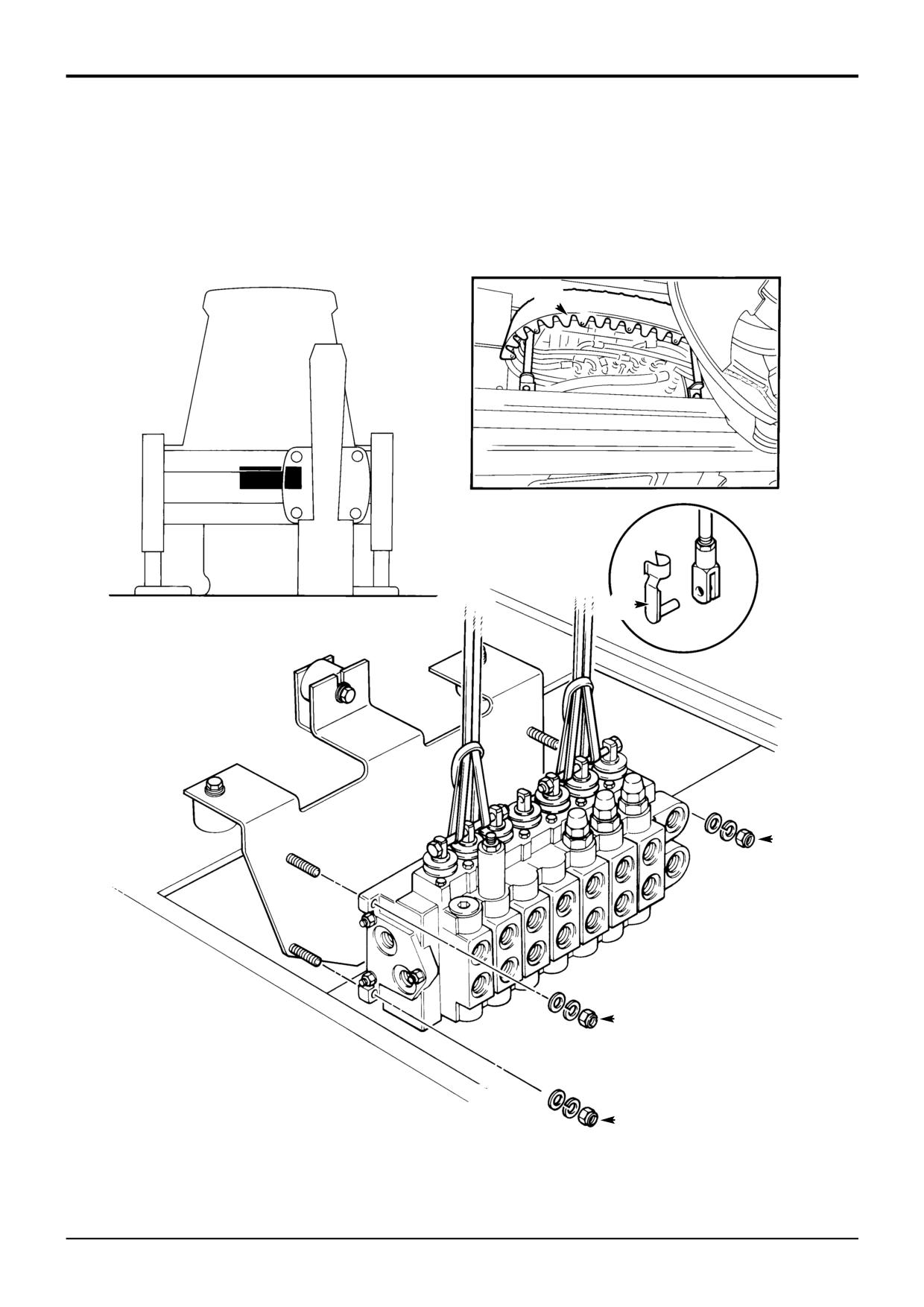
Removal
INT-3-1-10/1
1
Sideshift the carriage to one side as shown (sideshift
machines only). Lower the backhoe and loader end to
After replacement check the auxiliary relief valve (A.R.V.)
the ground and stop the engine.
pressure settings.
2
Operate the valve block levers back and forth to vent
Note: All hydraulic adapters that are installed together with a
residual pressure.
bonded sealing washer must also have JCB Threadseal
applied to the threads of the adapter.
3
Remove the hose guide A (this makes access to the
valve block easier).
3
Remove clevis pins B to disconnect the control levers
from the valve block spools.
4
Disconnect all hydraulic hoses from the valve block and
plug all orifices to prevent ingress of dirt. Label each
hose before disconnecting, this will ensure correct
position when refitting.
5
Insert two M10 bolts through the eye end spools (three
spools each end) as shown. Make sure the bolt has a
retaining nut on each end. When the bolts are in place
thread suitable slings around the bolts as shown.
! CAUTION
This component is heavy. Do not attempt to remove it
unless its weight is held by a sling. Make sure that the
sling is attached to a suitable lifting appliance.
HYD 2-3/1
7
Remove nuts C and lower the valve block to the
ground.
9803/3280
Issue 1
Section E
Hydraulics
Section E
60 - 6
Excavator Valve
60 - 6
11
11
11
11
15
9
14
11
11
13
15
15
10
3
4
3
6
5
11
11
1
A
B
7
2
2
A402450
8
A402460
9803/3280
Issue 2*
Section E
Hydraulics
Section E
60 - 7
Excavator Valve
60 - 7
Removal and Replacement
Precision Control (Servo)
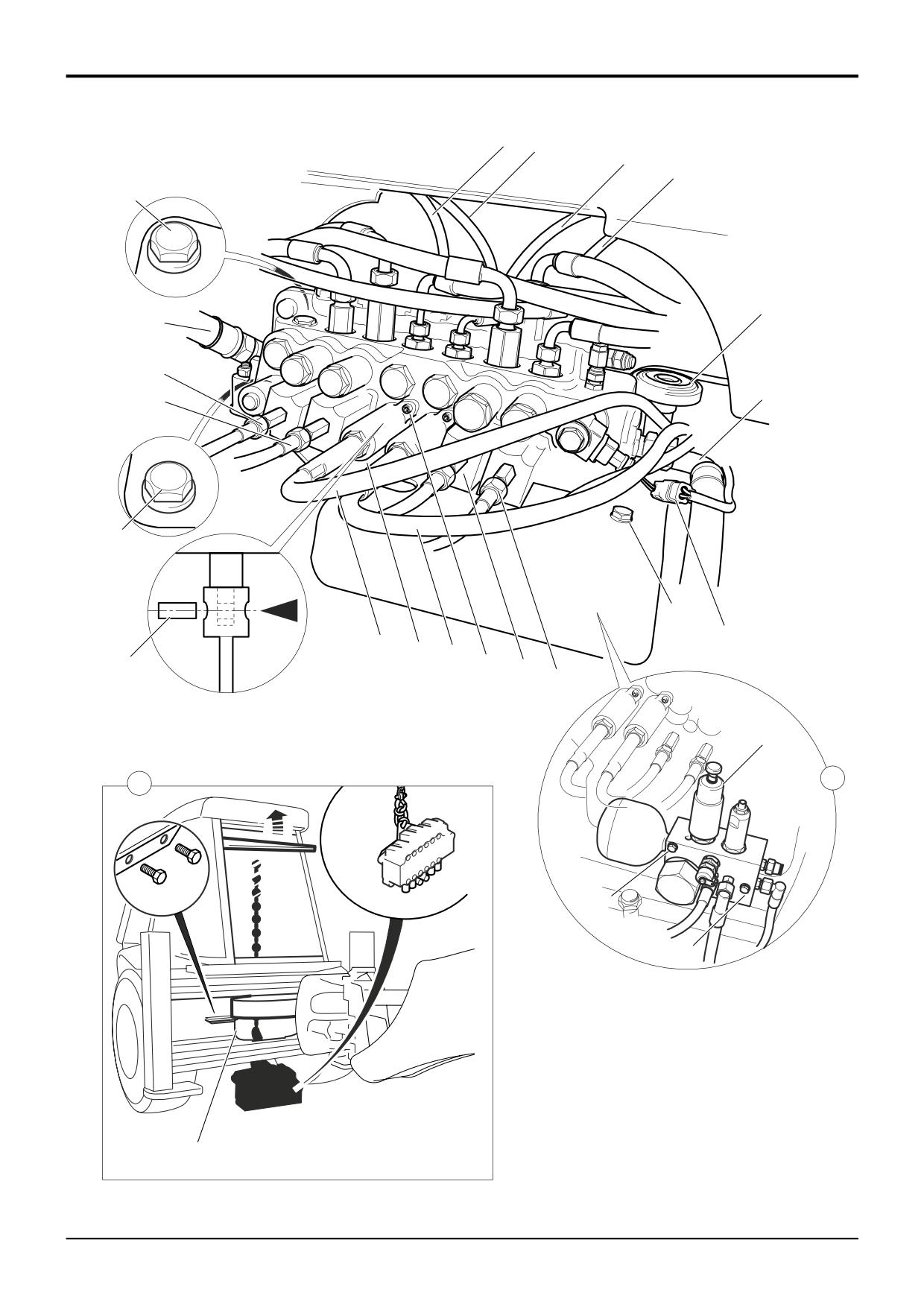
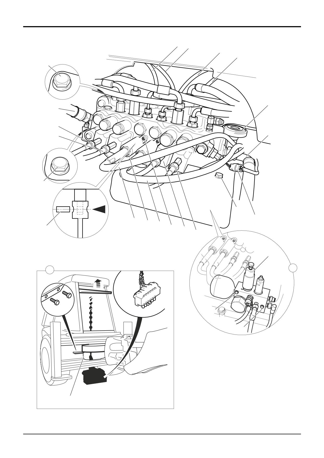
Disconnect the stabiliser spool control cables 3 as follows:
! DANGER
1
Undo the lock nut 4.
Hydraulic fluid at system pressure can injure you. Before
disconnecting or connecting hydraulic hoses, stop the
2
Undo the housing retaining screws 5 and slide the
engine and operate the controls to release pressure
housing down the cable.
trapped in the hoses. Make sure the engine cannot be
started while the hoses are open.
3
Push out the cable connecting pin 6 and disconnect
INT-3-1-11/1
the cable at the spool. Tie the cables out of harms way.
Removal
Remove the excavator valve as follows:
It is recommended that the valve is removed complete with
1
For access remove bolts 7 and tie hose guard 8 out of
its mounting plate. The assembly is lowered down and then
the way.
out from under the rear on the machine. Before commencing
make sure that there is sufficient clearance between the
2
Uncouple electrical connection to the rear horn 9.
machine and the ground. If necessary raise the rear of the
machine using the stabilisers. Chock the machine securely,
3
Uncouple electrical connection 10 to the hydraclamp
remembering to leave access for removal of the valve
solenoid.
assembly.
4
Record the phasing of the pilot hoses 11 connected at
The illustration is viewed from the bottom.
the top and bottom of the excavator valve. The hoses
should be labelled, if not label each hose before
Before proceding, vent the hydraulic pressure as follows:
disconnecting, this will ensure correct position when
refitting. Disconnect all hydraulic pilot hoses from the
1
Stop the engine. With the operator seat set in the rear
valve block and plug all open ends and ports to
facing position (for backhoe operation), switch the
prevent ingress of dirt.
starter to ON without starting the engine. Operate the
joystick controls several times to vent the hydraulic
5
Record the phasing of the service hoses connected at
pressure from the servo system and backhoe rams.
the front of the excavator valve. Label each hose
before disconnecting, this will ensure correct position
2
Operate the stabiliser controls several times to vent
when refitting. Disconnect all the hoses from the valve
pressure from the stabiliser rams.
block and plug all open ends and ports to prevent
ingress of dirt.
3
Turn the starter switch to the OFF position and remove
the key.
6
Disconnect the inlet 13 and tank return 14 hoses from
the valve block, plug all open ends and ports to
prevent ingress of dirt.
! WARNING
Make the machine safe before working underneath it.
7
Loosen the three mounting plate bolts 15 - DO NOT
Park the machine on level ground, lower the arms. Apply
completely remove the retaining bolts.
the parking brake, put the transmission in neutral and
stop the engine. Chock both sides of all four wheels.
! CAUTION
Disconnect the battery, to prevent the engine being
This component is heavy. Do not attempt to remove it
started while you are beneath the machine.
unless its weight is held by a sling. Make sure that the
GEN-1-2
sling is attached to a suitable lifting appliance.
HYD 2-3/1
To avoid damage to the pilot supply valve (shown at A),
8
Open the rear window. Remove the access plate in the
remove it as follows:
cab floor above the excavator valve. Attach a suitable
sling to the mounting bracket slinging point, make sure
1
Carfully tag all the hoses connected at the valve. Record
that the weight of the valve is supported by the sling
the phasing. Disconnect the hoses.
(shown at B).
2
Uncouple the solenoid electrical connector 1.
9
Remove bolts 15 and lower the valve block to the
ground.
3
Undo the two fixing bolts 2 and remove the valve.
10
If the hose adaptors are going to be removed from the
valve block, label before removing to ensure
replacement in the correct ports. Record the positions
of any restrictors.
9803/3280
Issue 2*
Section E
Hydraulics
Section E
60 - 8
Excavator Valve
60 - 8
11
11
11
11
15
9
14
11
11
13
15
15
10
3
4
3
6
5
11
11
1
A
B
7
2
2
A402450
8
A402460
9803/3280
Issue 2*
Section E
Hydraulics
Section E
60 - 9
Excavator Valve
60 - 9
Removal and Replacement (Cont’d)
Precision Control (Servo)
Replacement
Replacement is a reversal of the removal sequence.
Hoses and pipes (when applicable) must be re-connected
and phased in same position as removal.
! WARNING
Fine jets of hydraulic fluid at high pressure can
penetrate the skin. Do not use your fingers to check for
hydraulic fluid leaks. Do not put your face close to
suspected leaks. Hold a piece of cardboard close to
suspected leaks and then inspect the cardboard for
signs of hydraulic fluid. If hydraulic fluid penetrates your
skin, get medical help immediately.
INT-3-1-10/1
After replacement check the auxiliary relief valve (A.R.V.)
pressure settings.
Torque Settings
Item
Nm
kgf m
lbf ft
5
8 - 11
0.8 - 1.1
6 - 8
9803/3280
Issue 2*
Section E
Hydraulics
Section E
61 - 1
Excavator Valve
61 - 1
9803/3280
Issue 1
Section E
Hydraulics
Section E
61 - 2
Excavator Valve
61 - 2
Dismantling and Assembly
Manual Control
Assembly
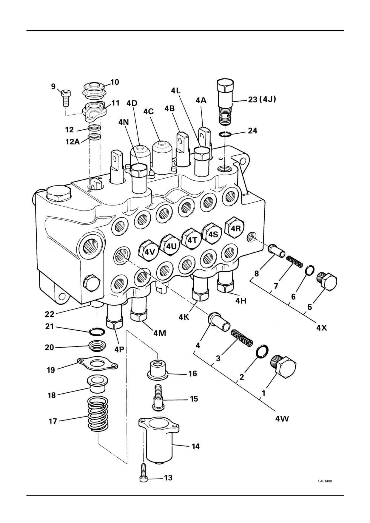
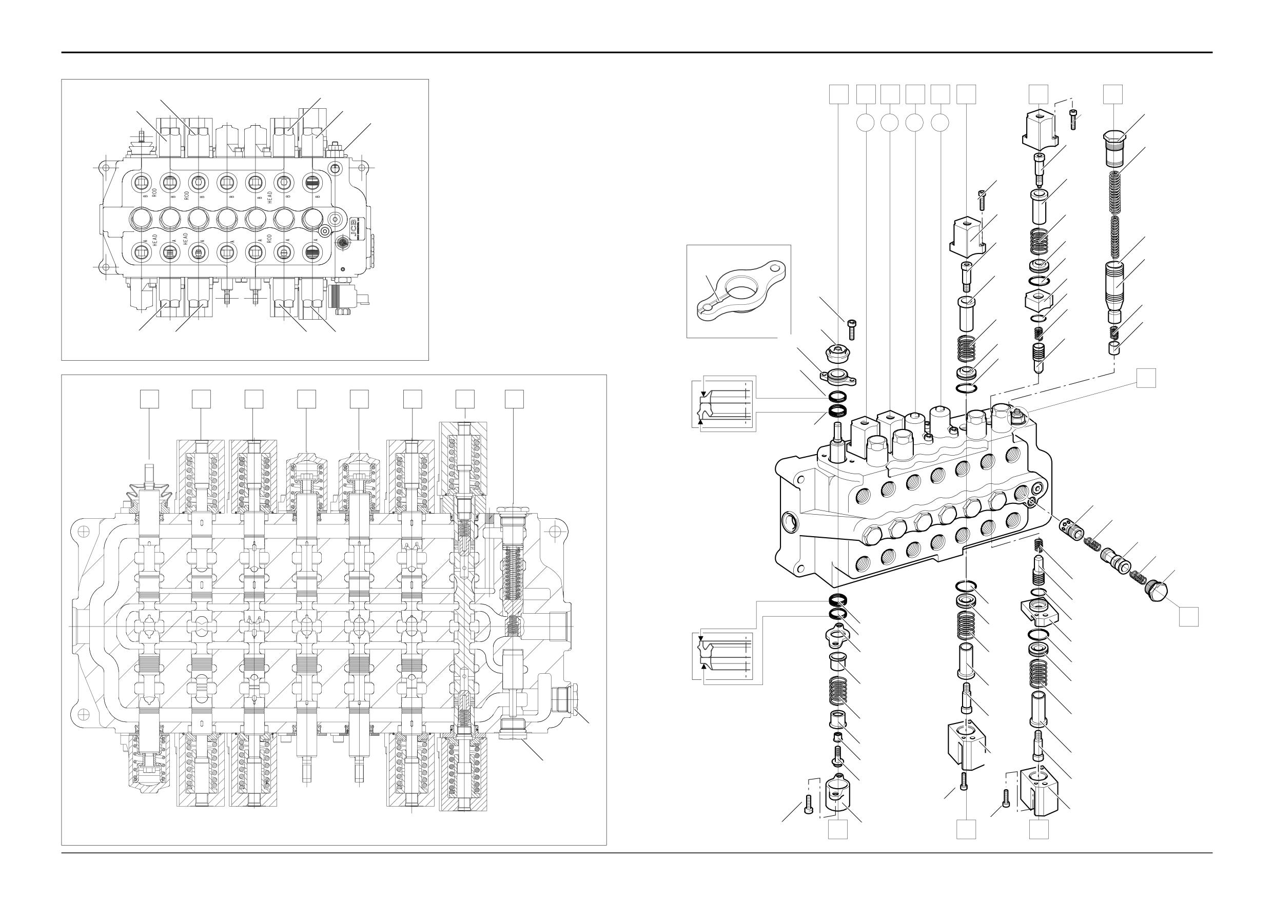
The numerical sequence shown on the illustration is intended
1
Fit the boot 10 to the seal plate 11.
as a guide to dismantling.
2
Fit a new lipseal 12A into the valve block, ensure
For assembly the sequence should be reversed.
square. Fit wiper 12 on top of lipseal.
Check Valves
3
Fit the seal plate and boot assembly to valve block but
do not torque tighten capscrews 9 at this stage. Ensure
wiper locates into seal plate.
Each of the identical load hold check valves 4R to 4W can
be removed as shown at 4W. Make-up check valve 4X is a
4
Use clean hydraulic oil as a lubricant. From the bottom,
smaller size but otherwise identical.
insert spool through the valve block, do not use
excessive force when fitting, a turning motion should
Ensure good condition of seating faces on poppets 4 and 8
ease the spool through the valve block.
and on the mating faces in the valve block.
5
Check that the tang end of the spool passes through
Spools
the boot without dislodging or damaging the boot.
Ensure that the tang aligns with the control rod and
Spools 4A, 4B, 4E and 4F are identical but must not be
that the boot is not distorted and is located in the spool
interchanged as they are matched to their bores. Stabiliser
land.
spools 4C and 4D are identical to each other but different
from the excavator spools.
6
Torque tighten cap screws 9.
All spools have the same centring and sealing components
7
When fitting bolt 15, clean the threads thoroughly using
items 9 to 21.
JCB Cleaner/Degreaser, leave it for 10 minutes then
apply a small quantity of JCB Threadlocker and Sealer
To completely dismantle a spool, follow the sequence 9 to
to the threads of the spool.
21. To prevent spool rotation when turning screw 15, hold a
rod through the eye end of the spool.
8
Make sure that all the parts move freely, check that
item 16 does not interfere with item 18.
If only renewing the seals, dismantle as far as cap 14 then
remove items 15 to 22 as an assembly.
9
Renew 'O' ring 21 and seal 20. Make sure the 'O' ring
and wiper seal are not trapped or damaged.
Lubricate new seals with JCB Hydraulic Fluid and take care
to prevent them from being damaged by the sharp edges of
10
Fit seal 20 and seal plate 19 to the valve block section.
the spool.
Torque tighten capscrew 13 on completion.
Apply JCB Threadlocker and Sealer to threads of screw 15.
Re-connect the lever mechanism to the tang (lever) end of
the spool.
Relief Valves
Run the engine and inspect the valve for external leaks.
A.R.V's 4H to 4P appear identical but have various pressure
settings, refer to Technical Data. Ensure that they are
Torque Settings
correctly adjusted and fitted in their specified positions.
Item
Nm
kgf m lbf ft
Relief valve dismantling and assembly procedures are
1
122
12.4
90
detailed separately.
5
80
8.3
60
9
9.5
0.96
7
Note: All hydraulic adapters that are installed together with a
13
7
0.7
5
bonded sealing washer must also have JCB Threadseal
15
11
1.1
8
applied to the threads of the adapter.
23
95
10
70
9803/3280
Issue 1
Section E
Hydraulics
Section E
61 - 3
Excavator Valve
61 - 3
Auxiliary Relief Valves
4Q 4N
4L 4J
A401470
4P 4M
4K 4H
B
A
S161700
9803/3280
Issue 2*
Section E
Hydraulics
Section E
61 - 4
Excavator Valve
61 - 4
Dismantling and Assembly
Auxiliary Relief Valves
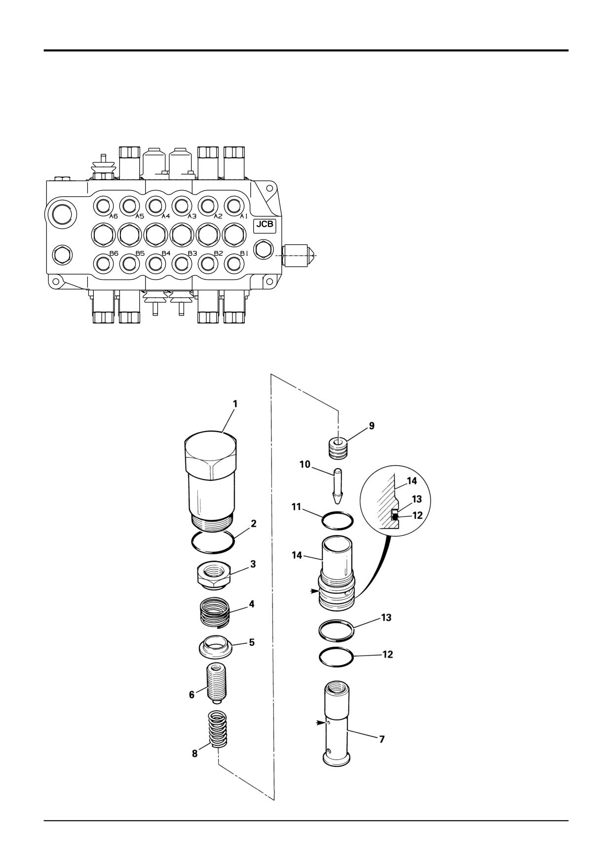
A.R.V. Position Key
Eight A.R.V's are fitted at positions 4H to 4Q. These are
identical in design but have various pressure settings, refer
Control Layout
to Technical Data.
JCB
ISO
Case
Ford
Note: Valve 4Q is only fitted to machines equipped with a
Slew Right
4H
4H
4H
4H
Powerbreaker.
Slew Left
4J
4J
4J
4J
The numerical sequence shown on the illustration is intended
Boom Rod
4K
4M
4M
4K
as a guide to dismantling.
Boom Head
4L
4N
4N
4L
Dipper Rod
4N
4L
4K
4N
For assembly the sequence should be reversed.
Dipper Head
4M
4K
4L
4M
Dismantling
Bucket Rod
4Q
4Q
4Q
4P
Bucket Head
4P
4P
4P
4Q
Dismantle sub-assembly 14 from item 1 using a special tool
(see Service Tools). The special spanner locates in cross
Note: The bucket rod side A.R.V. is only fitted to machines
holes B.
equipped with a Powerbreaker.
Dismantle sub-assembly 14 into its component parts.
Make sure that small drilling A is not blocked.
Discard old and worn O-rings and back-up rings.
Assembly
Renew all O-rings and back-up rings.
Lubricate O-rings and back-up rings with JCB Hydraulic
Fluid.
Fit back-up ring 13 on the upper side of 'O' ring 12 as shown
in the inset.
Fit flat face of sleeve 9 against shoulder of poppet 10.
Torque tighten item 14 using the special tool (see Service
Tools), until its shoulder seats firmly against item 1.
Pressure test the relief valves, refer to Service Procedures,
Excavator Valve - Pressure Testing.
Torque Settings
Item
Nm
kgf m
lbf ft
1
65
6.6
48
3
24
2.5
18
9803/3280
Issue 2*
Section E
Hydraulics
Section E
61 - 5
Excavator Valve
61 - 5
Dismantling and Assembly
Hydraclamp Valve - (Sideshift Machines)
(Not Precision Control Machines)
Torque Settings
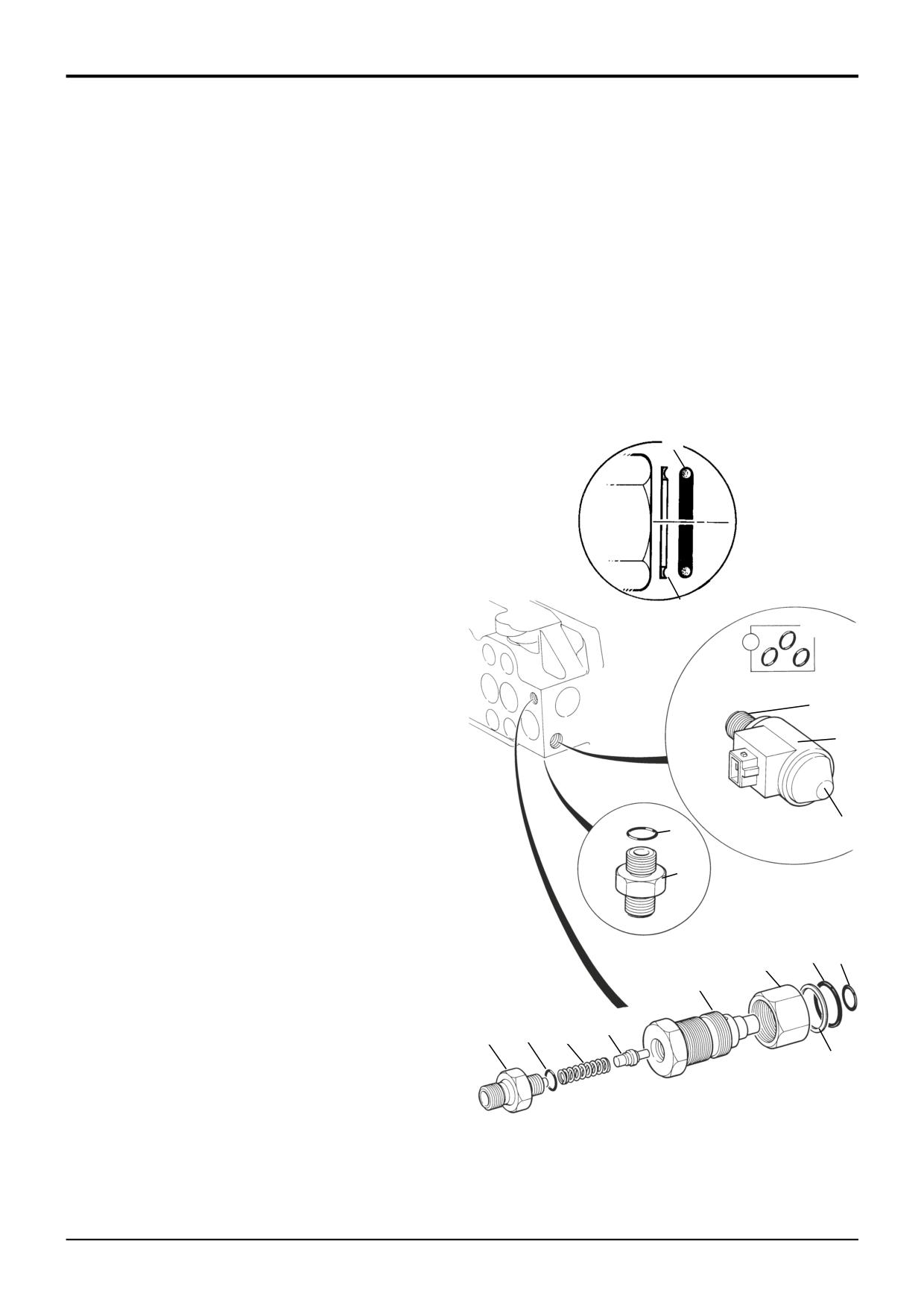
The numerical sequence shown on the illustration is intended
as a guide to dismantling. For assembly the sequence
should be reversed.
Item
Nm
kgf m
lbf ft
1
13.5
1.4
10
The following points MUST be avoided when dismantling
3
24.5
2.5
18
and assembling the valve:
5
13.5
1.4
10
• CONTAMINATION
11
5.5
0.5
4
• DAMAGE TO POPPET AND SEAT
13
24.5
2.5
18
• DAMAGE TO SEAL GROOVES
All or any of the above points may result in possible
problems with the valve.
A
When removing 'O' rings and seals, use an appropriately
2
rounded tool that WILL NOT cause any damage to the seal
grooves. Discard ALL 'O' rings DO NOT use worn or
damaged items.
Note that the hydraclamp comprises two separate valve
assemblies; 1) the check valve assembly (items 1 to 8); 2) the
solenoid assembly (items 11 to 14).
Dismantling
2A
Loosen nut 1 (turn anti-clockwise) and then remove the
14
check valve assembly from the valve block. If required, the
check valve assembly can be dismantled into its component
parts (items 1 to 8).
Inspect the valve components for scratches, nicks or any
13
other type of damage, particularly on the poppet and seat
12
faces. Replace with new if required.
Assembly
Renew all 'O' rings. The parts microfiche will identify the
correct seal kit part numbers for items 2, 2A, 4, 6, 10 and 14.
10
11
Fit seal 2A with the recess towards ‘O’ ring 2, as shown at A.
9
Lubricate parts with JCB Hydraulic Fluid before assembling.
Make sure that all the parts move freely.
Ensure that the small drilling through the centre of item 3, is
clear.
2
4
1
3
Do not over-tighten the solenoid assembly, it may affect the
operation of the solenoid, use the spanner flats and torque
tighten to figure indicated in the table below (items 11 and
8
5
6
7
13).
2A
Check the operation of the electric hydraclamp, refer to
Circuit Descriptions, Excavator Valve - Manual Control -
S217500
Hydraclamp Valve Operation.
9803/3280
Issue 2*
Section E
Hydraulics
Section E
61 - 6
Excavator Valve
61 - 6
Dismantling and Assembly
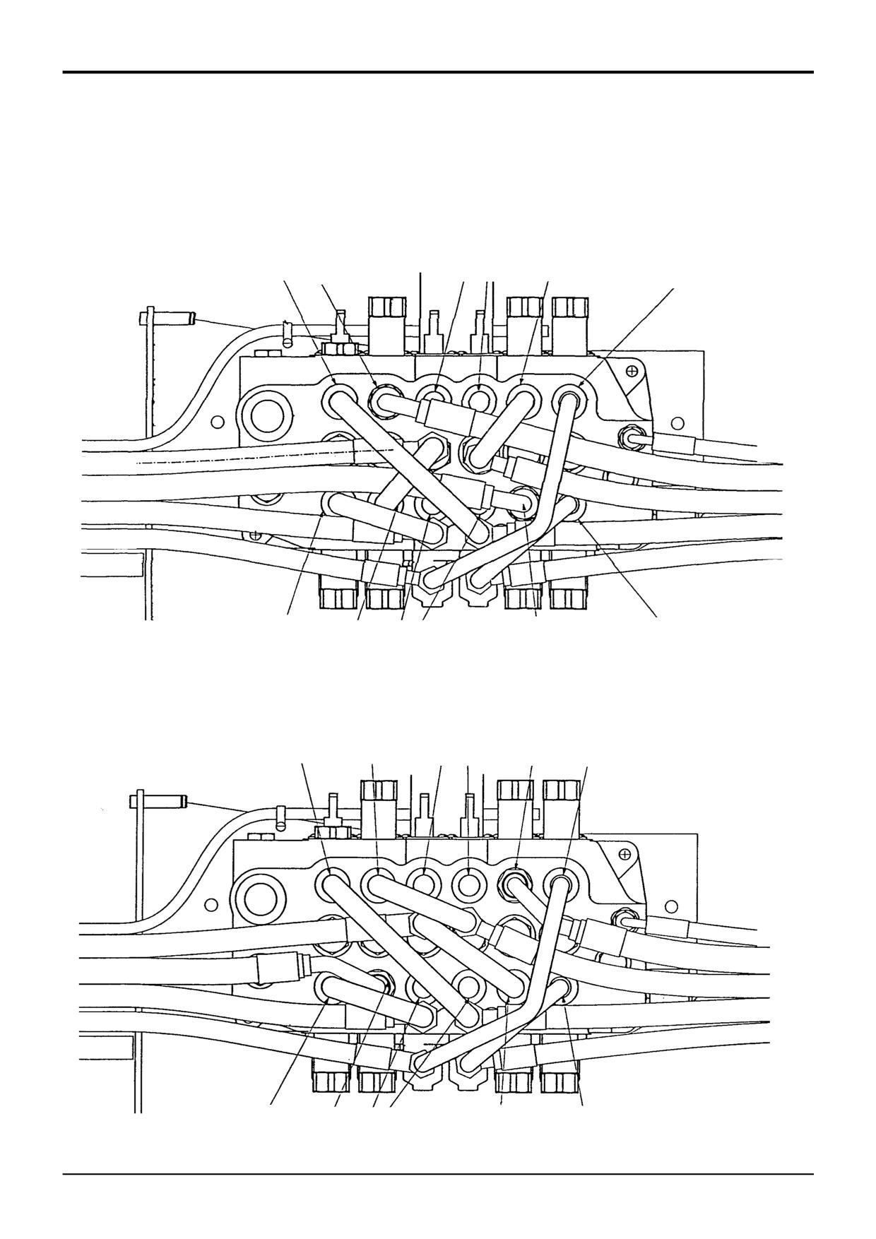
- Hoses and Pipes (Sideshift Valve)
Refer to Excavator Valve, Removal and Replacement for
valve block removal and replacement procedure. Hoses and
pipes (when applicable) must be re-connected and phased in
same position as removal.
CROWD BOOM
STABILISER DIPPER
SLEW
CLAMP
BOOM
BOOM
DIPPER
DIPPER
CROWD
CROWD
SLEW
SLEW
CROWD
DIPPER
SLEW
S270740
BOOM
STABILISER
ISO EXCAVATOR VALVE
CROWD
DIPPER
STABILISER
BOOM
SLEW
CLAMP
BOOM
BOOM
DIPPER
DIPPER
CROWD
CROWD
SLEW
SLEW
S270750
CROWD
DIPPER
STABILISER
BOOM
SLEW
JCB EXCAVATOR VALVE
9803/3280
Issue 2*
Section E
Hydraulics
Section E
61 - 7
Excavator Valve
61 - 7
Dismantling and Assembly
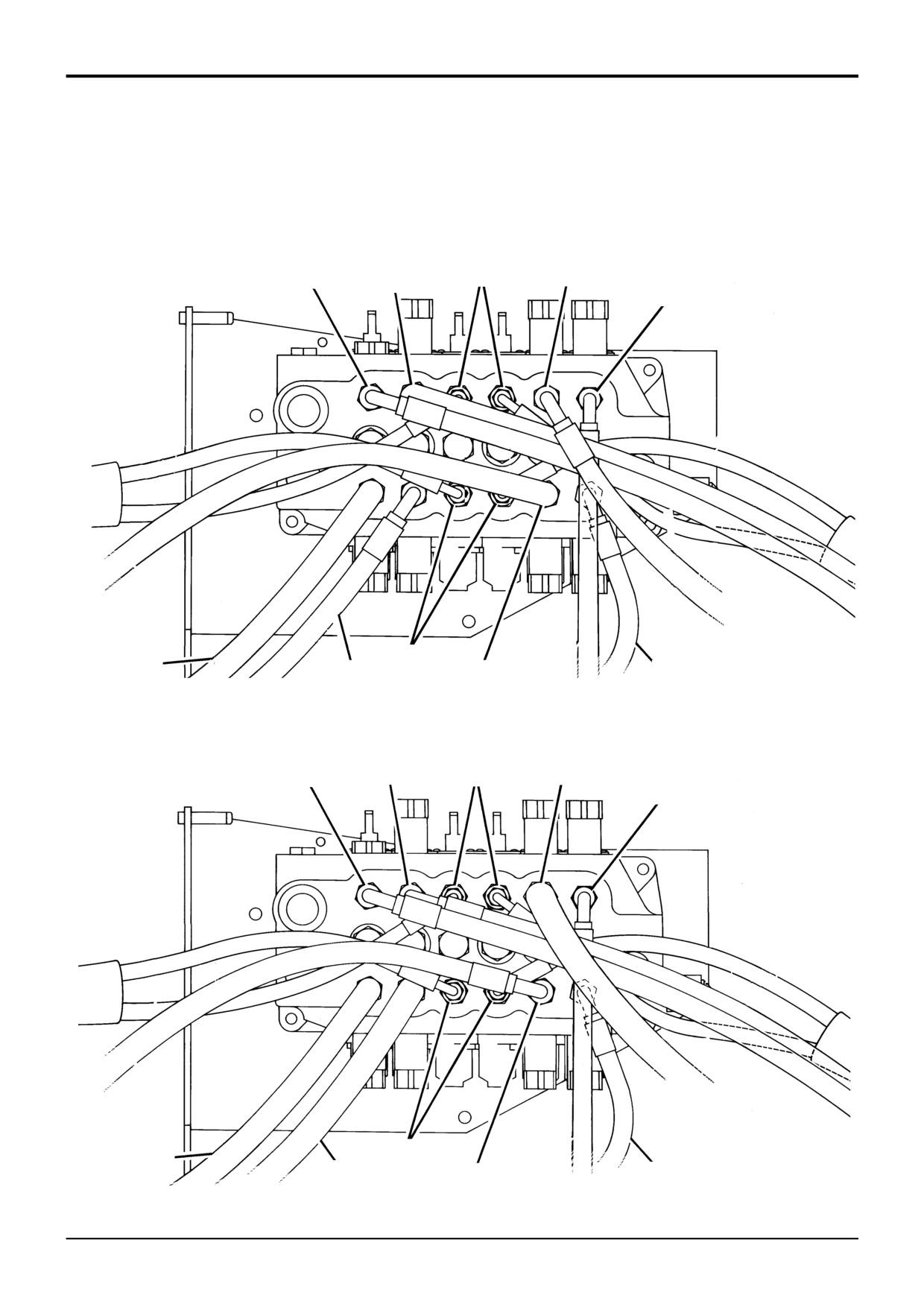
- Hoses and Pipes (Centremount Valve)
Refer to Excavator Valve, Removal and Replacement for
valve block removal and replacement procedure. Hoses and
pipes (when applicable) must be re-connected and phased in
same position as removal.
CROWD
STABILISER
DIPPER
BOOM
SLEW
STABILISER
CROWD
S273370
BOOM
DIPPER
SLEW
ISO EXCAVATOR VALVE
CROWD
DIPPER
STABILISER
BOOM
SLEW
STABILISER
CROWD
S273380
DIPPER
BOOM
SLEW
JCB EXCAVATOR VALVE
9803/3280
Issue 2*
Section E
Hydraulics
Section E
62 - 1
Excavator Valve
62 - 1
RE1
RB1
G
F
E
D
C
B
A
H
RF1
RA1
H1
A1
K
(B) (B) (G) (G)
A2
H2
A3
B1
B2
A4
JG
JF JE
JD
JC JB
JA
H3
B3
A5
A6
H4
N
B4
A7
G1
A8
H5
A9
B5
H6
G2
A402500
RF2
RE2
RB
2
RA2
A10
G3
B6
B7
G4
K
G
F
E
D
C
B
A
H
G5
J5
J4
J3
J2
J1
A21
A20
B14
JA
A19
G15
B13
G14
A18
G13
B12
A17
G12
A16
B11
A15
B10
G11
M
G10
B9
A14
L
G9
G8
A13
B8
A12
A11
A402510
G6
G
G7
B
A
A402600
9803/3280
Issue 2*
Section E
Hydraulics
Section E
62 - 2
Excavator Valve
62 - 2
Dismantling and Assembly
Precision Control (Servo)
(Machines up to serial no. 931159)
Introduction
Relief Valves
The numerical sequence shown on the illustration is intended
A.R.V's RA to RF appear identical but have various pressure
as a guide to dismantling. Be sure to note the location of all
settings, refer to Technical Data. Ensure that they are
components when dismantling. Although some components
correctly adjusted and fitted in their specified positions.
may appear to be identical they are not interchangeable.
Make sure that components are assembled in their original
Relief valve dismantling and assembly procedures are
positions.
detailed separately.
For assembly the sequence should be reversed.
Bypass Compensator Valve
Load Sense (Isolator/Compensator) Valves
The bypass compensator valve is shown at H. Note that the
assembly L is a blanking spool and would not normally need
Each of the load sense valves JA to JG can be removed as
to be removed.
shown at JA. Note that all valves are identical in appearance
except valve JE. This valve is of the same configuration but
Load Sense Drain Regulator and Relief Valve
is dimensionally different. Note that components are not
interchangeable, see the introduction above.
The dismantling and assembly procedure for the drain
regulator and relief valve assembly K is detailed separately,
Spools
see Drain Regulator and Relief Valve.
Note that the not all the spools are shown with their
components. This is because some spool assemblies are of
the same configuration:
When assembling apply JCB Threadlocker to the
For spools F and E see spool B.
following components:
For spools D and C see spool G. Note that the spools are
inverted relative to spool G.
A2
A13
Stabiliser spools 1D and 4E are identical to each other but
G8
different from the excavator spools. Spools must not be
interchanged as they are matched to their bores
Torque Settings
To dismantle spools C, D and G hold a rod through the eye
end of the spool to prevent it rotating when undoing the
Item
Nm
kgf m
lbf ft
screw at the opposite end. To dismantle spools B, E and F
A1
8 - 11
0.8 - 1.1
6 - 8
use allen keys in both screws, holding one whilst undoing the
A2
8 - 11
0.8 - 1.1
6 - 8
other. After removing one screw, hold the spool using
A11
8 - 11
0.8 - 1.1
6 - 8
service tool 992/10100 and then undo the remaining screw.
A13
8 - 11
0.8 - 1.1
6 - 8
B1
8 - 11
0.8 - 1.1
6 - 8
It is strongly recommended that that spool A is not
B3
17 - 21
1.7 - 2.1
12.5 - 15.5
dismantled. The spool has additional valve components in
B8
8 - 11
0.8 - 1.1
6 - 8
each end and can easily be damaged when dismantling. If
B10
17 - 21
1.7 - 2.1
12.5 - 15.5
the spool is damaged then the valve must be renewed. Only
G1
8 - 11
0.8 - 1.1
6 - 8
attempt to dismantle the spool in exceptional circumstances.
G6
8 - 11
0.8 - 1.1
6 - 8
G8
8 - 11
0.8 - 1.1
6 - 8
Lubricate new seals with JCB Hydraulic Fluid and take care
H1
58 - 72
6 - 7.3
43 - 53
to prevent them from being damaged by the sharp edges of
JA
58 - 72
6 - 7.3
43 - 53
the spool.
K
58 - 72
6 - 7.3
43 - 53
M
58 - 72
6 - 7.3
43 - 53
Note that the breather groove N in the seal retaining plates
RA - RF
58 - 72
6 - 7.3
43 - 53
G3 must be orientated facing the rear mounting face of the
valve block
9803/3280
Issue 2*
Section E
Hydraulics
Section E
62 - 3
Excavator Valve
62 - 3
1
2
3
4
5
6
14
8
7
6
8
7
13
12
11
10
11
9
A402640
9803/3280
Issue 3*
Section E
Hydraulics
Section E
62 - 4
Excavator Valve
62 - 4
Dismantling and Assembly
Precision Control (Servo)
(Machines up to serial no. 931159)
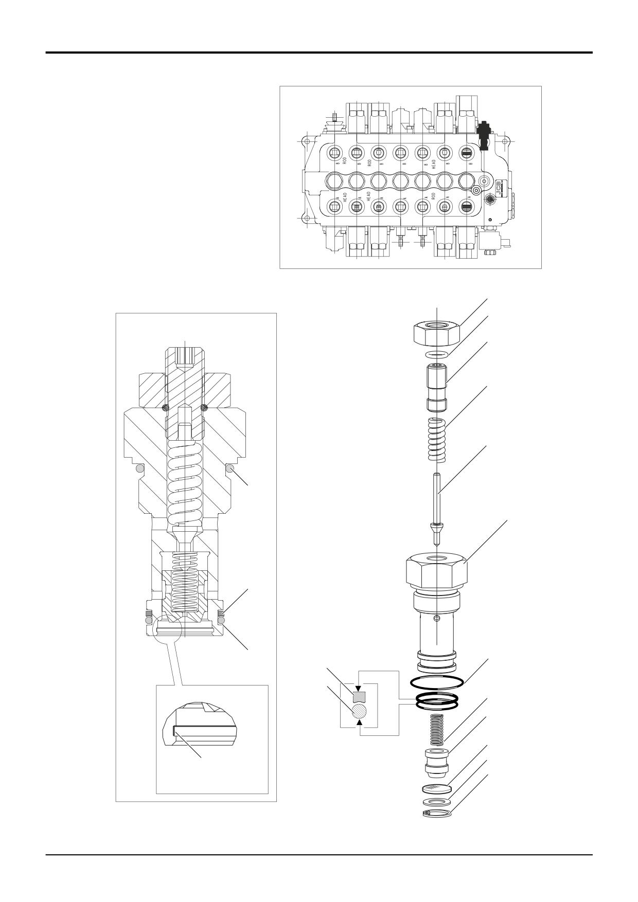
Load Sense Drain Regulator and Relief Valve
The numerical sequence shown on the illustration is intended
as a guide to dismantling.
Note that components 6 - 13 can be dismantled and
assembled without disturbing components 1 - 5. If
components 1 - 5 are dismantled, the valve must be reset to
the correct operating pressure after assembly.
For assembly the sequence should be reversed.
Great care should be taken when dismantling and
assembling a valve to avoid the following:-
Contamination
Damage to spools
Damage to seal grooves
Any of the above may result in possible problems with the
operation of the valve.
When Dismantling
When removing 'O' Rings and seals, use an appropriatly
rounded tool that WILL NOT cause any damage to the seal
grooves.
Discard ALL 'O' Rings and back-up rings. DO NOT use
worn or damaged items.
Inspection
Inspect the valve components for scratches, nicks or any
other type of damage, replace with new if required.
When Assembling
Renew all 'O' rings and back-up rings.
Lubricate parts with JCB Hydraulic Fluid before assembling.
Make sure that all the parts move freely.
Make sure that the ‘O’ rings and back-up rings are fitted the
correct way, items 7 and 8.
Be sure to fit filter screen 11 the correct way round.
Adjust pressure setting as required.
Torque Settings
Item
Nm
kgf m
lbf ft
1
8 - 11
0.8 - 1.1
6 - 8
9803/3280
Issue 2*
Section E
Hydraulics
Section E
62 - 5
Excavator Valve
62 - 5
Dismantling and Assembly
Precision Control (Servo)
Check the operation of the electric hydraclamp, refer to
(Machines up to serial no. 931159)
Circuit Descriptions, Excavator Valve - Precision Control
- Hydraclamp Valve Operation.
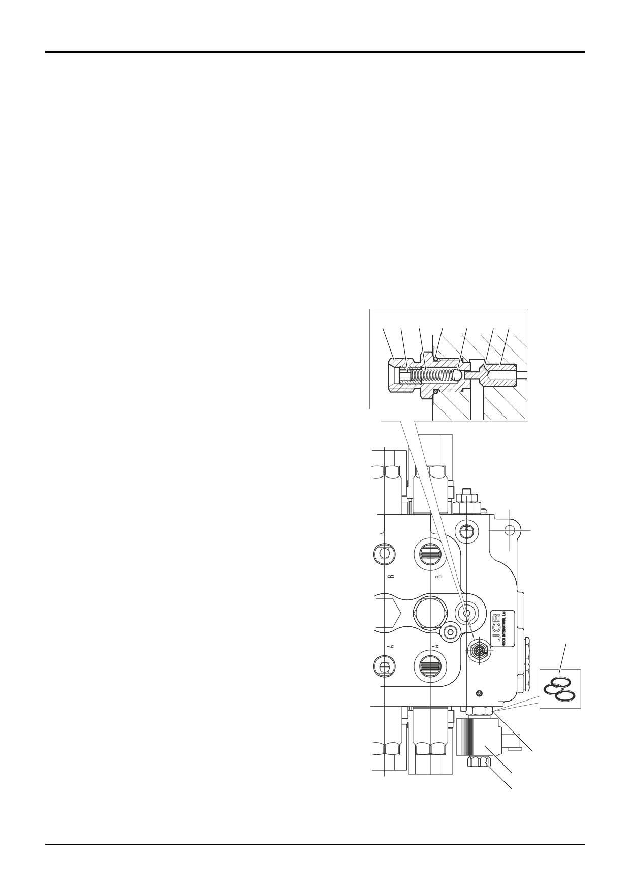
Hydraclamp Valve
The numerical sequence shown on the illustration is intended
Torque Settings
as a guide to dismantling. For assembly the sequence
should be reversed.
Item
Nm
kgf m
lbf ft
4
8 - 11
0.8 - 1.1
6 - 8
The following points MUST be avoided when dismantling
7
4.7 - 6.1
0.5 - 0.6
3.5 - 4.5
and assembling the valve:
9
41 - 48
4.1 - 5
30 - 36
• CONTAMINATION
• DAMAGE TO BALL SEAT AND PISTON
• DAMAGE TO SEAL GROOVES
All or any of the above points may result in possible
problems with the valve.
1
4
5
2
6
C
3
When removing 'O' rings and seals, use an appropriately
rounded tool that WILL NOT cause any damage to the seal
grooves. Discard ALL 'O' rings DO NOT use worn or
damaged items.
Note that the hydraclamp comprises two separate valve
assemblies; the clamp valve assembly shown at A and the
solenoid assembly shown at B.
Dismantling
A
Unsecrew the clamp valve assembly A from the excavator
valve block. Withdraw the piston 3 from the excvator valve
block, if necessary use thin nose pliers.
Hold the body 1 and undo the spring retaining plug 4.
Withdraw the spring 5 and ball 6.
Undo the nut 7 and remove solenoid coil 8. Undo the valve
stem 9.
Make sure that all components and associated cross drillings
are clean and free from debris.
Inspect the valve components for scratches, nicks or any
other type of damage, particularly on the ball and seat faces.
Carefully inspect the outside diameter of the piston 3 and its
bore in the excavator valve block for damage or excessive
10
wear. Renew components as required.
Assembly
Renew all 'O' rings.
Lubricate parts with JCB Hydraulic Fluid before assembling.
Make sure that all the parts move freely.
B
Ensure that the small drilling C in the piston 3 is clear.
9
Do not over-tighten the solenoid assembly, it may affect the
operation of the solenoid, use the spanner flats and torque
8
A402950
tighten to figure indicated in the table.
7
9803/3280
Issue 1
Section E
Hydraulics
Section E
62 - 20
Excavator Valve
62 - 20
Dismantling and Assembly
13
Precision Control (Servo)
(Machines from January 2003)
12
13
1
14
5
14A
2
9
3
6
10
11
6A
11A
8
A403840
4
7
9803/3280
Issue 1
Section E
Hydraulics
Section E
62 - 21
Excavator Valve
62 - 21
Dismantling and Assembly
Precision Control (Servo)
(Machines from January 2003)
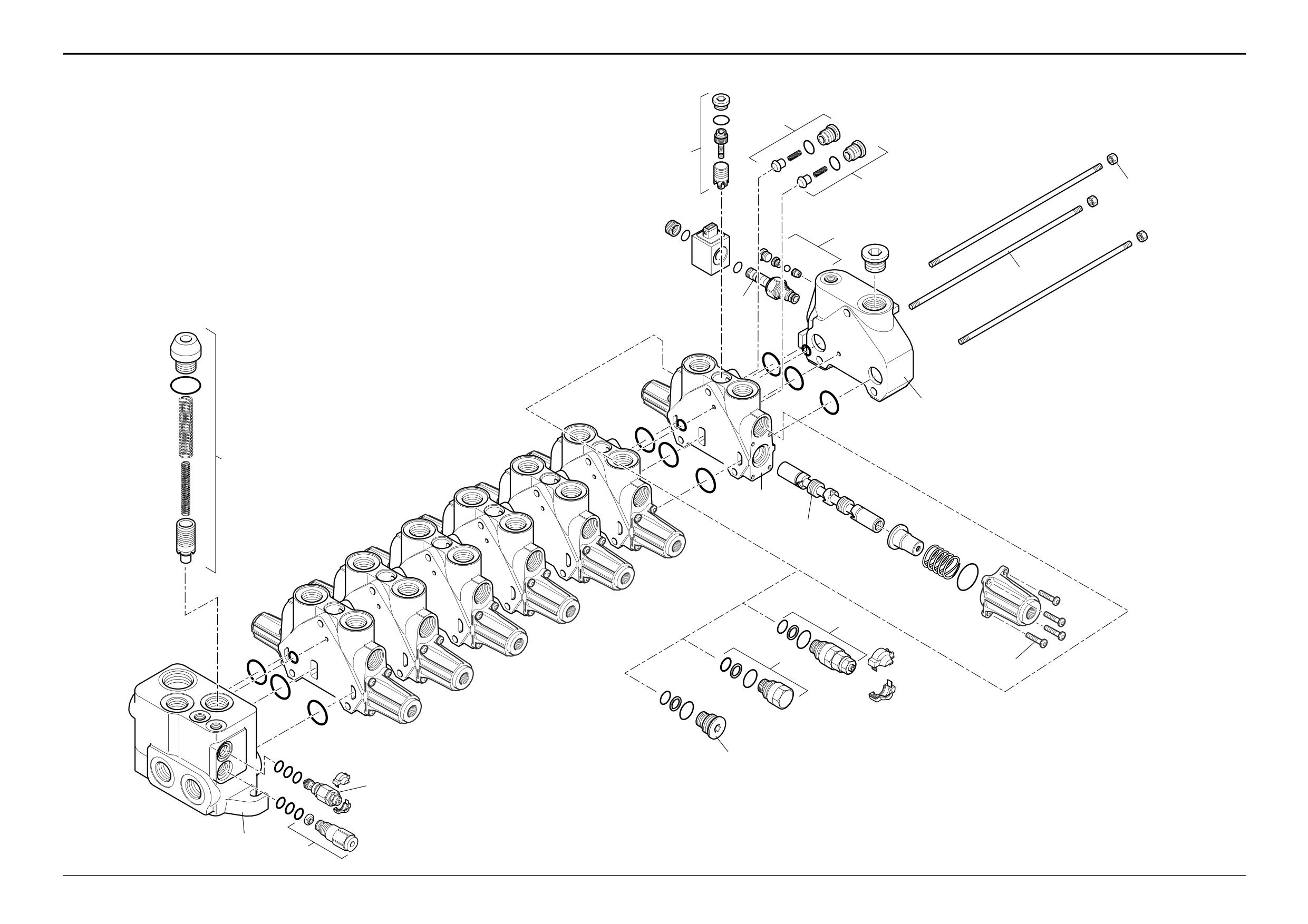
Dismantling
Service Spools
The excavator valve block is a ‘sandwich type’, which is
Each of the service spools 6 can be removed as shown.
made up of a number of separate sections. The illustration
shown on the opposite page is intended as a guide to
Care must be taken to ensure that the spool is not damaged
dismantling. Be sure to note the location of all components
when removing it from the block. Note that all spools are
when dismantling. Although some components may appear
similar in appearance but must not be interchanged as they
are matched to their bores. All spools have the same
to be identical they are not interchangeable. Make sure that
centring and sealing components.
components are assembled in their original positions.
1
Remove the excavator valve block from the machine.
Flow Regulator Valve
The dismantling and assembly procedures for the flow
regulator valve 7 are detailed separately, refer to Flow
2
Remove the three tie rod nuts 1.
Regulator Valve.
3
Carefully separate and remove the outlet section 2
followed by the remaining service sections 3. If the inlet
Load Sense Relief Valve
section 4 is to be replaced, remove and retain the tie
The dismantling and assembly procedures for the load
sense relief valve 8 are detailed separately, refer to Load
rods 5.
Sense Relief Valve.
Assembly
Flushing Valve
The flushing valve 9 can be removed as shown.
Assembly is the reverse of the dismantling sequence.
Auxiliary Relief Valves
1
Clean the valve components in an appropriate solvent.
The A.R.V's 10 appear identical but have various pressure
Ensure that the mating faces of the valve sections are
settings, refer to Technical Data. Ensure that they are
thoroughly clean before assembly.
correctly adjusted and fitted in their specified positions.
The dismantling and assembly procedures for the ARV’s are
2
Renew the ‘O’ rings located between the valve sections.
detailed separately, refer to Auxiliary Relief Valves (ARV’s).
Make sure the ‘O’ ring seals are not trapped or
damaged.
Anti-cavitation Valve
The dismantling and assembly procedures for the
3
Lubricate parts with JCB Hydraulic Fluid before
anticavitation valve 11 are detailed separately, refer to Anti-
assembling. Make sure that all the parts move freely.
cavitation Valve.
Torque Settings
Pressure Compensator Valves
Each of the pressure compensator valves 12 can be
Item
Nm
kgf m
lbf ft
removed as shown. Note that all valves are identical in
1
35
3.6
25.8
appearance. Note that components are not interchangeable.
6A
10
1
7.4
7
20
2
14.8
Load Hold Check Valves
8
45
4.6
33.2
Each of the load hold check valves 13 can be removed as
9
100
10.2
73.8
shown. Note that all valves are identical in appearance.
10
70
7.1
51.6
Ensure good condition of seating faces on poppets and on
11
70
7.1
51.6
the mating faces in the valve block.
11A
70
7.1
51.6
12
60
6.1
44.3
Hydra-clamp Solenoid Valve
13
30
3
22.1
The hydra-clamp solenoid valve 14 can be removed as
14
20
2
14.8
shown.
14A
45
4.6
33.2
9803/3280
Issue 1
Section E
Hydraulics
Section E
62 - 22
Excavator Valve
62 - 22
Dismantling and Assembly
Assembly
Assembly is the reverse of the dismantling sequence.
Precision Control (Servo)
(Machines from January 2003)
1
Clean the valve components in an appropriate solvent.
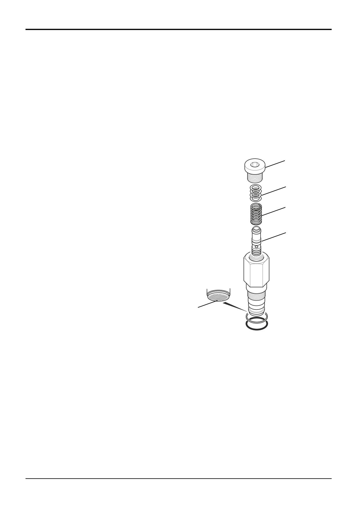
Flow Regulator Valve
2
Renew all 'O' rings and back-up rings.
3
Lubricate parts with JCB Hydraulic Fluid before
Removal
assembling. Make sure that all the parts move freely.
It is possible to remove a valve without removing the
4
Be sure to fit filter gauze 5 the correct way round.
excavator valve block from the machine.
Note: If removing components from a valve block that is
fitted on a machine the pilot circuit accumulator pressure
must be vented first. With the operator seat locked in the
rear facing position and with the arm rests raised forward (for
1
backhoe operation), switch the starter to ON without starting
the engine. Operate the joystick controls several times to
vent the hydraulic pressure from the servo system and
backhoe rams. Turn the starter switch to the OFF position
2
and remove the key.
1
Gain access to the excavator valve and disconnect and
3
blank any hoses or pipes which may interfere with the
removal of the flow regulator valve.
2
Unscrew the flow regulator valve from the excavator
4
valve block. Cover the ports to prevent the ingress of
dirt and remove to a clean working area.
Dismantling
Great care should be taken when dismantling and
assembling a valve to avoid the following:-
• Contamination
• Damage to spools
• Damage to seal grooves
5
Any of the above may result in possible problems with the
operation of the valve.
A403850
1
Unscrew and remove top plug 1.
2
Carefully remove shims 2, spring 3 and piston 4.
Note: When removing 'O' Rings and seals, use an
appropriatly rounded tool that WILL NOT cause any damage
to the seal grooves.
Discard ALL 'O' Rings and back-up rings. DO NOT use worn
or damaged items.
Inspection
1
Inspect the valve components for scratches, pitting,
corrosion or any other type of damage.
2
Clean the filter gauze 5 fitted in the end of the valve
body.
Note: If any part other than ‘O’ rings are damaged the entire
valve must be renewed.
9803/3280
Issue 1
Section E
Hydraulics
Section E
62 - 23
Excavator Valve
62 - 23
Dismantling and Assembly
Assembly
Assembly is the reverse of the dismantling sequence.
Precision Control (Servo)
(Machines from January 2003)
1
Clean the valve components in an appropriate solvent.
Load Sense Relief Valve
2
Renew all 'O' rings and back-up rings.
3
Lubricate parts with JCB Hydraulic Fluid before
Removal
assembling. Make sure that all the parts move freely.
It is possible to remove a valve without removing the
4
Adjust the pressure setting as required. Refer to
excavator valve block from the machine.
Service Procedures, Pressure Testing, Load Sense
Relief Valve.
Note: If removing components from a valve block that is
fitted on a machine the pilot circuit accumulator pressure
must be vented first. With the operator seat locked in the
1
rear facing position and with the arm rests raised forward (for
backhoe operation), switch the starter to ON without starting
the engine. Operate the joystick controls several times to
vent the hydraulic pressure from the servo system and
2
backhoe rams. Turn the starter switch to the OFF position
and remove the key.
1
Gain access to the excavator valve and disconnect and
blank any hoses or pipes which may interfere with the
removal of the load sense relief valve.
3
2
Unscrew the load sense relief valve from the excavator
valve block. Cover the ports to prevent the ingress of
dirt and remove to a clean working area.
Dismantling
Great care should be taken when dismantling and
assembling a valve to avoid the following:-
• Contamination
4
• Damage to spools
• Damage to seal grooves
Any of the above may result in possible problems with the
operation of the valve.
5
1
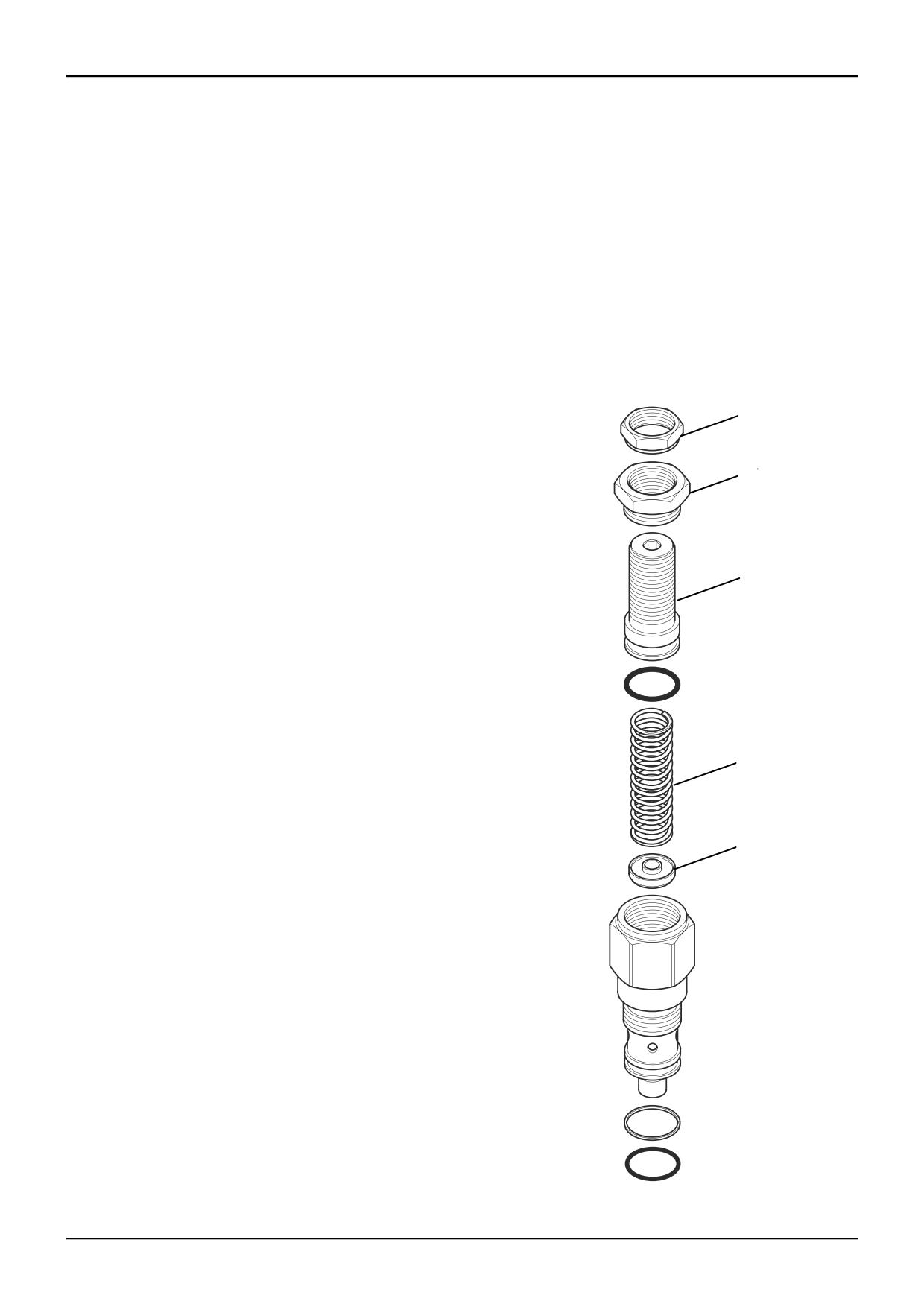
Loosen locknut 1, unscrew and remove adjuster nut 2
and adjuster screw 3.
2
Carefully remove spring 4 and poppet 5 from valve
body.
Note: When removing 'O' Rings and seals, use an
appropriatly rounded tool that WILL NOT cause any damage
to the seal grooves.
Discard ALL 'O' Rings and back-up rings. DO NOT use worn
or damaged items.
Inspection
1
Inspect the valve components for scratches, pitting,
corrosion or any other type of damage.
A403860
Note: If any part other than ‘O’ rings are damaged the entire
valve must be renewed.
9803/3280
Issue 1
Section E
Hydraulics
Section E
62 - 24
Excavator Valve
62 - 24
Dismantling and Assembly
Assembly
Assembly is the reverse of the dismantling sequence.
Precision Control (Servo)
(Machines from January 2003)
1
Clean the valve components in an appropriate solvent.
Auxiliary Relief Valves (ARV’s)
2
Renew all 'O' rings and back-up rings.
3
Lubricate parts with JCB Hydraulic Fluid before
Removal
assembling. Make sure that all the parts move freely.
It is possible to remove a valve without removing the
4
Adjust the pressure setting as required. Refer to
excavator valve block from the machine.
Service Procedures, Auxiliary Relief Valve - Setting.
Note: If removing components from a valve block that is
fitted on a machine the pilot circuit accumulator pressure
must be vented first. With the operator seat locked in the
1
rear facing position and with the arm rests raised forward (for
backhoe operation), switch the starter to ON without starting
2
the engine. Operate the joystick controls several times to
vent the hydraulic pressure from the servo system and
backhoe rams. Turn the starter switch to the OFF position
3
and remove the key.
1
Gain access to the excavator valve and disconnect and
4
blank any hoses or pipes which may interfere with the
removal of the auxiliary relief valve(s).
2
Unscrew the auxiliary relief valve(s) from the excavator
5
valve block. Cover the ports to prevent the ingress of
dirt and remove to a clean working area.
Dismantling
Great care should be taken when dismantling and
assembling a valve to avoid the following:-
• Contamination
• Damage to spools
• Damage to seal grooves
6
Any of the above may result in possible problems with the
operation of the valve.
1
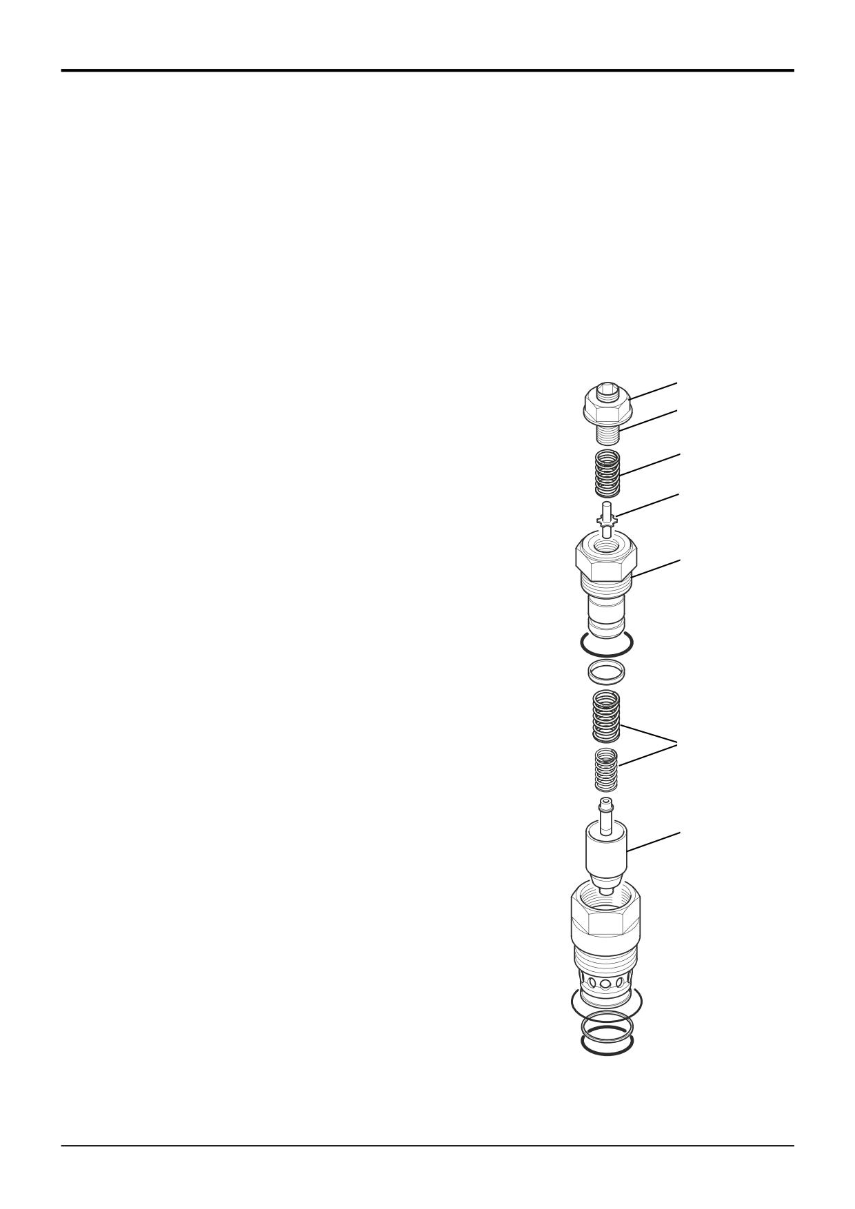
Prise off plastic locking cap.
7
2
Loosen locknut 1 and remove adjuster screw 2.
3
Carefully remove spring 3 and poppet 4.
4
Unscrew upper valve body 5 and remove springs 6 and
piston 7.
Note: When removing 'O' Rings and seals, use an
appropriatly rounded tool that WILL NOT cause any damage
to the seal grooves. Discard ALL 'O' Rings and back-up
rings. DO NOT use worn or damaged items.
Inspection
1
Inspect the valve components for scratches, pitting,
A403870
corrosion or any other type of damage.
Note: If any part other than ‘O’ rings are damaged the entire
valve must be renewed.
9803/3280
Issue 1
Section E
Hydraulics
Section E
62 - 25
Excavator Valve
62 - 25
Dismantling and Assembly
Assembly
Assembly is the reverse of the dismantling sequence.
Precision Control (Servo)
(Machines from January 2003)
1
Clean the valve components in an appropriate solvent.
Anti-cavitation Valve
2
Renew all 'O' rings and back-up rings.
3
Lubricate parts with JCB Hydraulic Fluid before
Removal
assembling. Make sure that all the parts move freely.
It is possible to remove a valve without removing the
excavator valve block from the machine.
Note: If removing components from a valve block that is
1
fitted on a machine the pilot circuit accumulator pressure
must be vented first. With the operator seat locked in the
rear facing position and with the arm rests raised forward (for
backhoe operation), switch the starter to ON without starting
the engine. Operate the joystick controls several times to
vent the hydraulic pressure from the servo system and
backhoe rams. Turn the starter switch to the OFF position
and remove the key.
1
Gain access to the excavator valve and disconnect and
blank any hoses or pipes which may interfere with the
removal of the anti-cavitation valve.
3
2
Unscrew the anti-cavitation valve from the excavator
valve block. Cover the ports to prevent the ingress of
dirt and remove to a clean working area.
2
Dismantling
Great care should be taken when dismantling and
assembling a valve to avoid the following:-
• Contamination
• Damage to spools
• Damage to seal grooves
Any of the above may result in possible problems with the
operation of the valve.
1
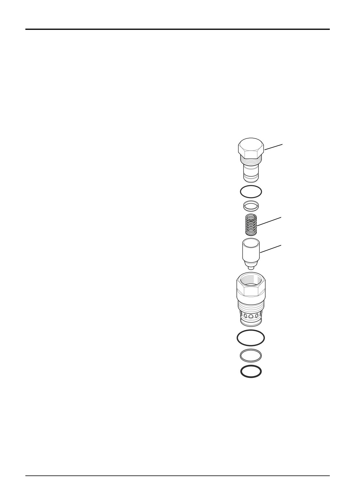
Unscrew and carefully remove the top nut 1 complete
with piston 2 from the valve body.
2
Remove the piston 2 and spring 3 from the top nut
spindle.
Note: When removing 'O' Rings and seals, use an
A403880
appropriatly rounded tool that WILL NOT cause any damage
to the seal grooves.
Discard ALL 'O' Rings and back-up rings. DO NOT use worn
or damaged items.
Inspection
1
Inspect the valve components for scratches, pitting,
corrosion or any other type of damage.
Note: If any part other than ‘O’ rings are damaged the entire
valve must be renewed.
9803/3280
Issue 1
Section E
Hydraulics
Section E
70 - 1
Hose Burst Protection Valves
70 - 1
Removal and Replacement
! WARNING
4
Disconnect all hydraulic hoses from the HBPV and plug
all orifices to prevent ingress of dirt. Label each hose
Make the machine safe before working underneath it.
before disconnecting, this will ensure correct position
Park the machine on level ground, lower the arms. Apply
when refitting.
the parking brake, put the transmission in neutral and
stop the engine. Chock both sides of all four wheels.
5
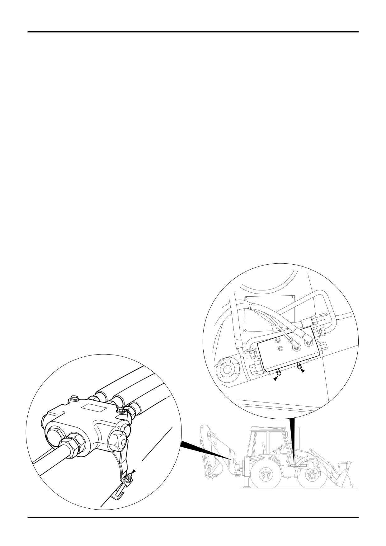
Undo the retaining clips A and remove the HBPV.
Disconnect the battery, to prevent the engine being
Replacement
started while you are beneath the machine.
GEN-1-2
Replacement is a reversal of the removal sequence.
! DANGER
! WARNING
Hydraulic fluid at system pressure can injure you. Before
disconnecting or connecting hydraulic hoses, stop the
Fine jets of hydraulic fluid at high pressure can
engine and operate the controls to release pressure
penetrate the skin. Do not use your fingers to check for
trapped in the hoses. Make sure the engine cannot be
hydraulic fluid leaks. Do not put your face close to
started while the hoses are open.
suspected leaks. Hold a piece of cardboard close to
INT-3-1-11/1
suspected leaks and then inspect the cardboard for
signs of hydraulic fluid. If hydraulic fluid penetrates your
Removal
skin, get medical help immediately.
INT-3-1-10/1
1
Park the machine on firm level ground, engage the
parking brake and set the transmission to neutral.
After refitting the valve to the machine, ensure that the valve
Lower the backhoe and loader end to the ground and
operates correctly, refer to Service Procedures, Hose
stop the engine.
Burst Protection Valves - Checking.
Note: Refer to Service Procedures, Hose Burst Protection
Valves, Lowering a Load - In a Failure Condition for
lowering a load with engine failure or a burst hose.
2
Turn the manual over-ride screw fully clockwise.
3
Operate the main service control levers back and forth
to vent residual pressure. For instance, if the HBPV is
fitted on the boom or dipper then operate the backhoe
control levers. If the HBPV is fitted on the loader arms
then operate the loader control levers.
A
A
324250
A
323590
A260734
9803/3280
Issue 1
Section E
Hydraulics
Section E
70 - 2
Hose Burst Protection Valves
70 - 2
Dismantling and Assembly
- Loader Lift Ram
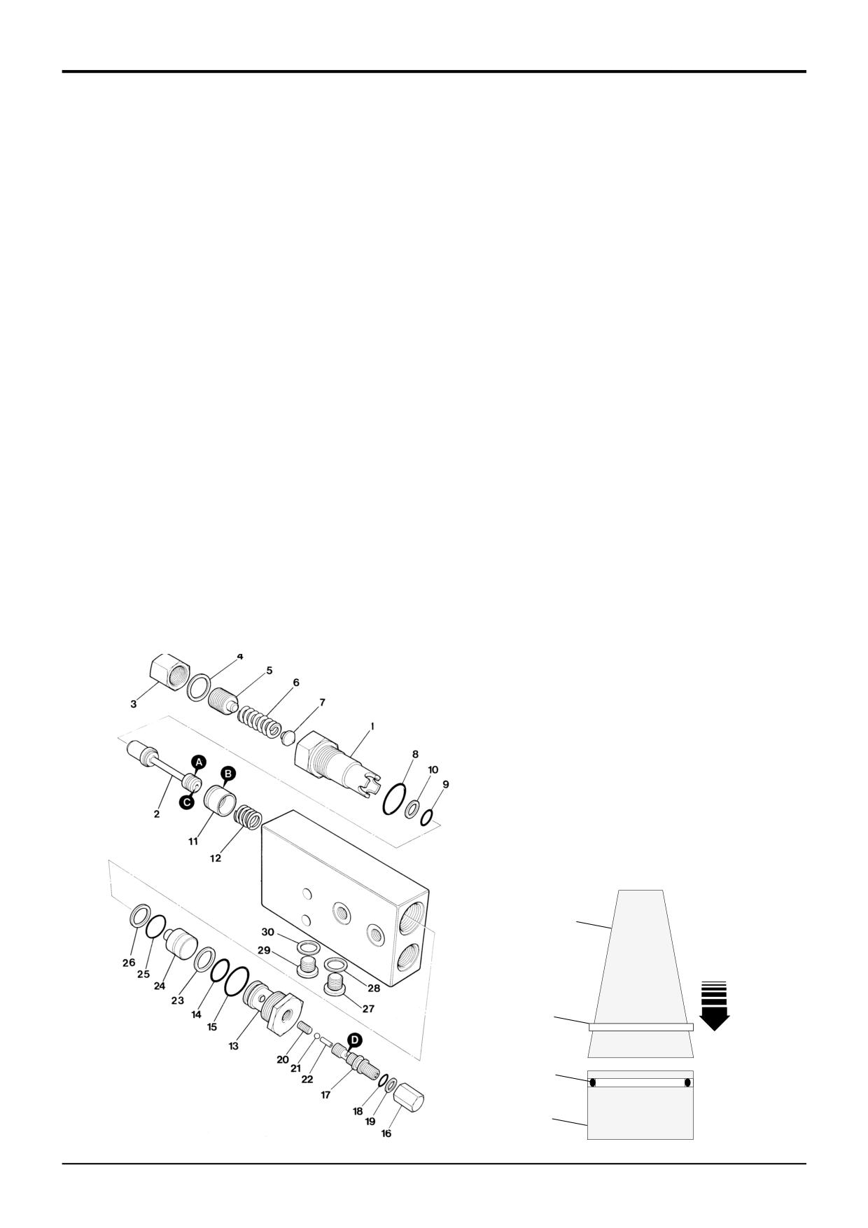
This procedure applies to Hose Burst Protection Valves
Assembly
fitted to the loader arm rams ONLY.
DO NOT apply JCB Threadlocker and Sealer or any other
The numerical sequence shown on the illustration is
type of locking fluid to the threads of item 17. The threads
intended as a guide to dismantling.
form an integral part of the valve operating sequences -
applying locking fluid to the threads will seriously effect the
For assembly the sequence should be reversed.
operation of the valve.
Dismantling
Ensure that the small drilled holes C and D in items 2 and 17
respectively are not blocked.
If possible, avoid disturbing pressure settings, remove
cartridges by unscrewing hexagons 1 and 13 and do not
Renew all seals. If fitting new Teflon rings A & B, use a
remove capnuts 3 and 16.
conical guide, such as item E, to expand the rings gradually.
Complete the ring fitting procedure as quickly as possible,
Spool 2 and check valve 11 each have a Teflon ring fitted
otherwise the ring will stretch. See below.
(items A and B respectively). These Teflon rings should only
be removed and replaced with new ones if they are
Note: There is an O-ring F fitted underneath each Teflon
damaged.
ring, if the Teflon rings are to be renewed, make sure that
new O-rings are fitted first.
Do not try to dismantle items 20, 21 and 22 (these items are
shown for pictorial reference only). To clean, use a non-
After assembly, make sure that the valve parts move freely,
metallic probe to move the ball 21 against spring 22 whilst
if they don't, check that all the seals are correctly fitted.
assembly 17 is submersed in cleaning fluid.
After refitting the valve to the machine, ensure that pressure
Check condition of all visible seating faces. If any are
settings are correct, see Technical Data page, and check
damaged, renew complete cartridge or valve assembly.
that the valve operates correctly.
Check valve bores and spools for nicks, scratches or
If the pressure settings were disturbed, then the valve must
scoring, if necessary, renew complete cartridge or valve
be re-set, refer to Service Procedures, Hose Burst
assembly.
Protection Valves, Pressure Testing - Loader Lift Ram.
E
B
F
325780
11
A183490
9803/3280
Issue 1