JCB 3CX, 4CX, 214e, 214, 215, 217 & VARIANTS Backhoe Loader. Service Manual - page 21
Section E
Hydraulics
Section E
88 - 2
Hydraulic Rams
88 - 2
Dismantling and Assembly
Assembly
- Power Sideshift Ram
1
Clean the threads of the end caps and cylinder using a
wire brush.
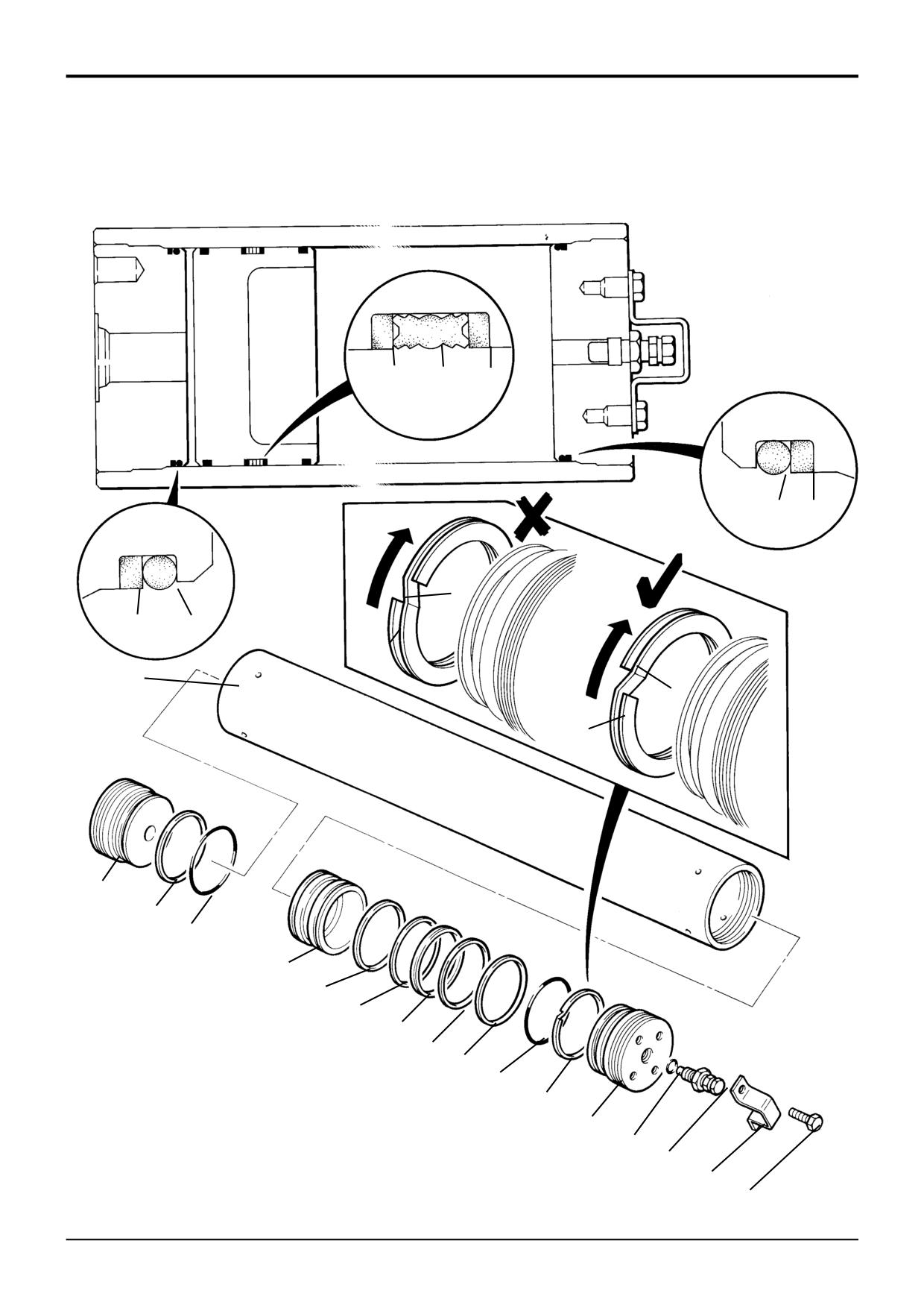
The numerical sequence shown on the illustration is
intended as a guide to dismantling.
2
Use JCB Cleaner/Degreaser to ensure that all threads
are free from grease, hydraulic oil and sealant. Allow 15
For assembly the sequence should be reversed.
minutes for solvent to dry before applying JCB
Threadlocker and Sealer (High Strength).
Dismantling
Ensure that lubricants used during assembly do not
1
Fix the ram assembly on a locally manufactured
come into contact with the JCB Threadlocker and
strip/rebuild bench as shown at A.
Sealer (High Strength).
2
Remove both end caps 1, (46mm AF). Pull the piston
3
Refer to JCB Ram Sealing Procedure for the correct
rod assembly from the cylinder.
method of fitting seals to the end cap and piston head.
Note 1: DO NOT allow the piston rod to come into contact
4
Clamp the cylinder vertically and lower the piston rod
with the cylinder bore. The cylinder bore may be damaged
assembly in from the top, as shown at B. Take care not
by careless dismantling.
to allow the piston rod to come into contact with the
cylinder bore. Be sure to engage the piston head new
3
Position the piston rod assembly on a bench in place of
wear rings and seal carefully into the cylinder. If the
the ram cylinder. Remove the wear rings 2 and seal 3
piston head wear rings or seal are damaged during this
from the piston head.
stage, they must be renewed.
Note 2: The piston head cannot be removed from the rod. If
5
Fit new ‘O’ rings 8 to spacers 7, slide onto the piston
there is damage to the rod or piston head, replace the
head and rod assembly.
complete assembly.
6
Apply JCB Activator to threads of the end caps and
4
Carefully inspect the bore of the cylinder and the piston
cylinder. Allow Activator to dry for 15 minutes before
rod outer diameter for scoring, nicks and burrs. If such
bringing into contact with the JCB Threadlocker and
damage is visible the components must be renewed.
Sealer (High Strength).
Note 3: If burrs are evident on the ends of the piston rod at
Note 4: Neither the JCB Threadlocker and Sealer (High
positions C or D remove by careful filing.
Strength) nor Activator must be allowed to contact seals,
bearing rings or ‘O’ rings.
5
Remove the end cap seal 4, wiper seal 5 and ‘O’ ring 6,
both end caps are the same
7
Apply JCB Threadlocker and Sealer (High Strength) to
threads of the ends caps, fit new ‘O’ rings 6.
6
Remove spacers 7 and ‘O’ rings 8.
8
Ensure that there are no burrs at the ends of the piston
rod, see Dismantling - Note 3:
9
Fit an end cap over the piston rod. Apply light hand
pressure to the cap to engage the gland seal on the
piston rod. DO NOT use excessive force. Screw on the
first end cap and then fix the assembly on the
strip/rebuild bench as shown at A. Fit the remaining
cap and then torque tighten both caps.
Note
5: If hydraulic oil contacts the uncured JCB
Threadlocker and Sealer (High Strength) a weakening of the
bond will result. Cure times vary according to the ambient
temperature. Allow a minimum of
2 hours between
assembly and filling the ram with oil.
Torque Settings
Item
Nm
kgf m lbf ft
1
400
40.8
295
9803/3280
Issue 1
Section E
Hydraulics
Section E
89 - 1
Hydraulic Rams
89 - 1
JCB Ram Sealing Procedure
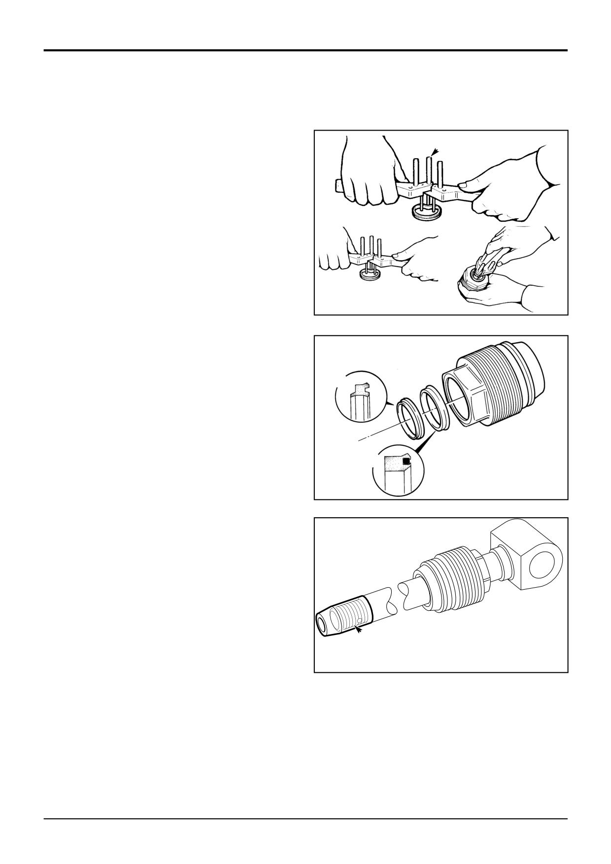
To fit new rod seal:
Use seal fitting tool (892/00334) to fit rod seals, the size
A
B
(diameter) and position of pins A is determined by the
diameter and radial width of the rod seal being fitted.
The pins are screwed into threaded holes in the tool body,
the spacing of the holes is designed to suit small or large
diameter rod seals.
1
Open the tool as shown at B and insert the new rod
seal, the seal must be fitted behind the two front pins
C
D
but in front of the rear pin as shown.
Note: Make sure the seals are fitted the correct way round,
as shown at P and Q.
161750
2
Close the tool as shown at C. The seal must form a
reniform (kidney shape).
3
Before fitting the rod seals check the seal grooves are
free of contamination and sharp edges,
4
Locate the seal in the end cap groove, shown at D,
P
when the seal is in position, open the tool to release the
seal. Make sure the seal is correctly installed in its
groove and remove the tool.
5
Fit rod wiper seal P into seal groove. Make sure the seal
is correctly installed as shown.
Q
Note: Some rod wipers, ie power track rod, may use a metal
encased seal which is pressed into the housing. Care must
be taken to ensure the seal is square before it is pressed in.
153212
Sleeve E must be used to protect the rod seals from damage
when fitting end cap onto the piston rod. There are various
sizes of sleeve, see Service Tools. Make sure the hexagon
on the end cap is towards the eye end of the rod.
E
A187361
9803/3280
Issue 1
Section E
Hydraulics
Section E
89 - 2
Hydraulic Rams
89 - 2
JCB Ram Sealing Procedure (continued)
Fit new piston head seals:
6
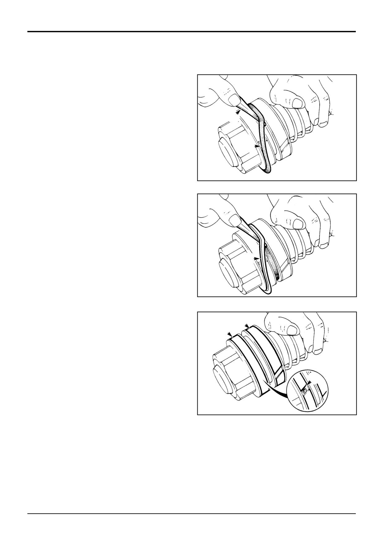
Use a blunt instrument (892/01027) shown at F, lever
the inner seal G into the piston head seal groove, do not
let the seal twist. There are identification marks on the
outer diameter of the seal, make sure the marks are
visible and the seal is free to rotate, if not remove the
F
seal and refit
7
Fit outer seal H using the same procedure as step 6.
Check the external grooves are visible.
G
8
Ensure O ring is fitted into the internal seal groove on
the piston head. Screw the piston head onto the thread
338470
of the piston rod, refer to the relevant section for torque
figure and completion of ram assembly.
9
Fit the piston head retaining dowel, see ram dismantling
and assembling relevant section
10
Fit wear rings J and K. Rotate the wear rings so that the
piston retention dowel is covered by the wear ring, NOT
as shown at L.
Fit the piston rod and head assembly into the cylinder:
11
Insert the piston/rod assembly into the cylinder. Align
H
the rod and head assembly until parallel with the
cylinder then push the assembly into the cylinder.
12
Fit the end cap, refer to the relevant section for torque
338480
figure and completion of ram assembly.
K
J
L
338490
9803/3280
Issue 1
Section E
Hydraulics
Section E
95 - 1
Hydraulic Oil Cooler
95 - 1
Removal and Replacement
! WARNING
Replacement
Raised loader arms can drop suddenly and cause serious
injury. Before working under raised loader arms, fit the
Replacement is a reversal of the removal sequence.
loader arm safety strut.
GEN 3-2
! WARNING
! DANGER
Fine jets of hydraulic fluid at high pressure can
Hydraulic Pressure
penetrate the skin. Do not use your fingers to check for
Hydraulic fluid at system pressure can injure you. Before
hydraulic fluid leaks. Do not put your face close to
disconnecting or connecting hydraulic hoses, stop the
suspected leaks. Hold a piece of cardboard close to
engine and operate the controls to release pressure
suspected leaks and then inspect the cardboard for
trapped in the hoses. Make sure the engine cannot be
signs of hydraulic fluid. If hydraulic fluid penetrates your
started while the hoses are open.
skin, get medical help immediately.
INT-3-1-11/1
INT-3-1-10/1
Removal
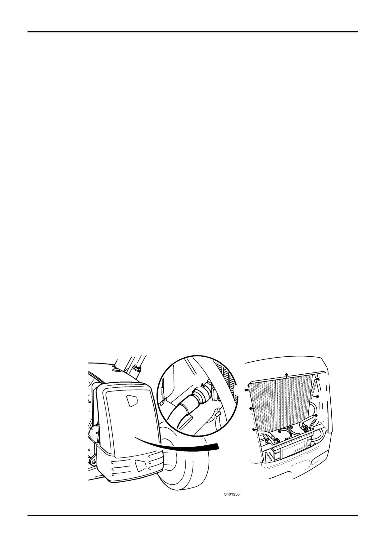
When installing and removing hoses from the cooler, it is
essential to note that adaptor C must be held with a
1
Park the machine on firm level ground, engage the
spanner whilst installing or removing the hose. Tighten hose
parking brake and set the transmission to neutral.
connections to a torque of 58 Nm (42 lbf ft).
Lower the backhoe and loader end to the ground and
stop the engine.
2
Vent residual hydraulic pressure by operating the
controls back and forth several times.
3
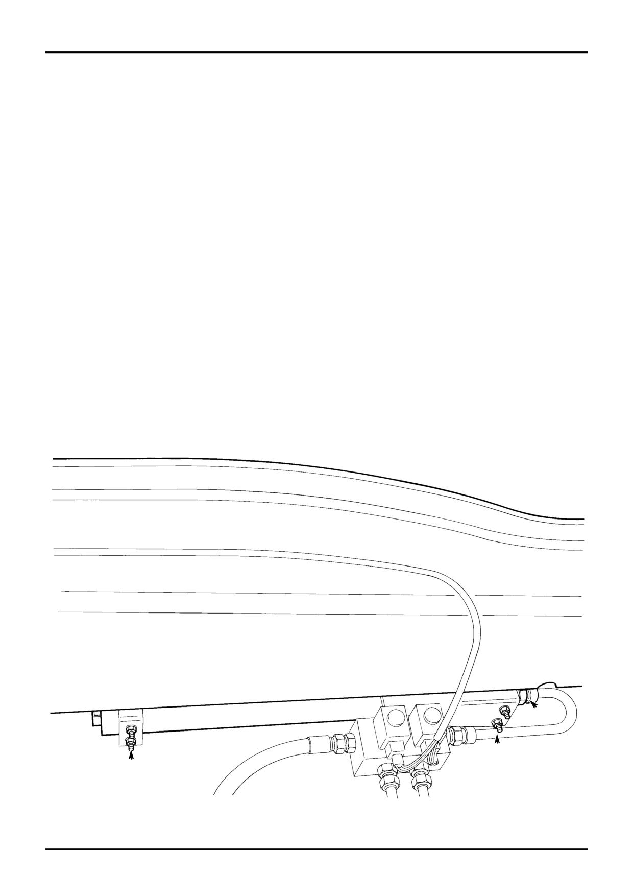
Label and then remove hydraulic hoses A and B (see
note). Plug and cap all open ports to prevent loss of
fluid and ingress of dirt.
Note: When installing and removing hoses from the cooler, it
is essential to note that adaptor C must be held with a
spanner whilst installing or removing the hose. It may be
easier to remove the top hose connection once the cooler
has been removed from the machine (disconnect top hose at
connection D).
4
Loosen and remove cooler mounting bolts E (4 off) and
remove the cooler F.
F
C
B
A
E
E
B
A
A401100
9803/3280
Issue 1
Section E
Hydraulics
Section E
96 - 1
Smooth Ride System
96 - 1
Accumulator
Removal and Replacement
Removal
Replacement
1
Park the machine on level ground, lower the loader
Replacement is a reverse of removal.
arms, switch off the engine and chock all four wheels.
Release all hydraulic pressure in the accumulator by
1
Charge the accumulator, refer to Service Procedures,
selecting the SRS ON and operating the loader arm
Smooth Ride System - Charging/Discharging the
hydraulic lever.
Accumulator.
2
Operate the machines hydraulic system. Check for
! DANGER
correct operation and leaks.
Before disconnecting or dismantling the accumulator
discharge all gas pressure. Failure to comply can cause
3
Replenish the hydraulic system with the recommended
rapid discharge of gas and/or hydraulic fluid which can
hydraulic fluid as required, refer to Section 3 Fluids,
result in death, personal injury and damage to the
Lubricants, Capacities and Specifications.
machine.
Hyd 2-5
2
Discharge the accumulator, refer to Service
Procedures,
Smooth
Ride
System
-
Charging/Discharging the Accumulator.
3
Disconnect hydraulic hose A and plug.
4
Loosen both ‘U’ clamps B and slide the accumulator
towards the front of the machine. When clear of the ‘U’
clamps carefully lower and withdraw accumulator.
A
B
B
S308290
9803/3280
Issue 1
Section E
Hydraulics
Section E
96 - 2
Smooth Ride System
96 - 2
10
9
10
8
7
A
7
8
7
1
A
7
5
7
8
6
11
10
9
10
11
8
7
4
13
12
3
S308280
2
9803/3280
Issue 1
Section E
Hydraulics
Section E
96 - 3
Smooth Ride System
96 - 3
Accumulator
Dismantling and Assembly
Assembly
Dismantling
1
Coat all internal components with clean hydraulic oil.
! DANGER
Before disconnecting or dismantling the accumulator
2
Fit piston seal 9, teflon back up rings 10 and seals 11.
discharge all gas pressure. Failure to comply can cause
rapid discharge of gas and/or hydraulic fluid which can
3
Fit piston assembly into bore 1 with hollow side
result in death, personal injury and damage to the
towards the gas end. Do not let piston seal drag on
machine.
threads, the piston must go into the bore exactly
HYD 2-5
square and very slowly. The piston is a tight fit, use a
hammer and a block of wood to tap the piston until all
1
Check that the accumulator has been discharged, refer
of the piston is 2in. (50mm) below the beginning of
to Service Procedures, Smooth Ride System -
honed bore.
Charging/Discharging the Accumulator.
Note: Keep pressure on the piston while tapping through
2
Secure the accumulator in horizontal position.
the bore chamfer, otherwise the piston will bounce back,
damaging the piston ring.
! CAUTION
The gas end cap (cap with gas valve) must be removed
4
Fit end cap back up seal 7. Make sure the seal is fitted
before the hydraulic end cap. This allows any residual
with leading edge A pointing in a counter clockwise
pressure to escape through the safety vent holes. If the
direction otherwise the seal will bind when the end cap
hydraulic end cap is removed first the piston will cover
is fitted.
the safety vent holes, which could result in the piston
being forced out under pressure which may result in
5
Fit end cap ‘O’ rings 8, it is important that seals 7 and 8
personal injury.
are fitted in the correct position in relation to each other
HYD 2-6
to prevent leaks.
3
Fit three pins into the holes in gas end cap 4, using a
6
Fit end caps 4 and 5, use pins and a long bar. Make
long bar working against the pins unscrew the end cap.
sure the gas end cap is fitted to the correct end, piston
hollow end to gas side.
4
Fit three pins into the holes in hydraulic end cap 5,
using a long bar working against the pins unscrew the
Note: The end caps will stop against the chamfer leading
end cap.
into the honed bore, ‘O’ ring sealing is not dependent upon
cap tightness.
5
Remove and discard ‘O’ rings and back up rings from
end caps.
7
Use new ‘O’ ring 13 and fit the gas valve 12.
6
Remove the piston 6 by pushing from the hydraulic end
with a bar.
! CAUTION
Do not remove the piston by applying compressed air at
the opposite end.
HYD 2-7
7
Remove piston seal and ‘O’ rings.
Inspection
Inspect piston for cracks, burrs around the ‘O’ ring grooves,
or damage. Examine the body bore 1, using a light, for
scratches or scoring. Inspect end caps for damaged threads
or burrs on ‘O’ ring grooves.
Minor nicks, scratches or light scoring of the body bore may
be removed by using a very fine paper. Dress the bore until
all apparent imperfections have been removed.
All seals and ‘O’ rings must discarded and new ones fitted.
9803/3280
Issue 1
Section F
Transmission
Section F
i
i
Contents
Page No.
Service Tools
1-
1
Technical Data
Wheels and Tyres
2-
1
Axles
3-
1
Synchro Shuttle Gearbox
4-
1
Powershift Gearbox - 6 Speed
5-
1
Powershift Gearbox - 4 Speed
6-
1
Engine Stall Speed Combinations
7-
1
Basic Operation
Axles
15 -
1
Synchro Shuttle Gearbox
Component Identification
16 -
2
Principle of Operation
16 -
2
Hydraulic and Electrical Operation
16 -
4
Powershift Gearbox
Component Identification
17 -
2
Principle of Operation
17 -
2
Hydraulic and Electrical Operation
17 -
4
ShiftMaster Operation Characteristics
17 -
5
Drive Paths - 4 Speed
18 -
1
Drive Paths - 6 Speed
18 -
5
Torque Converter
Component Identification
20 -
1
Principle of Operation
20 -
1
Systems Description
Synchro Shuttle Gearbox
Syncromesh (Blocking Pin Type)
25 -
2
Forward/Reverse Clutch Operation
26 -
1
2/4 Wheel Drive Clutch Operation
- Pressure ON/Spring OFF Type
27 -
1
*
- Spring ON/Pressure OFF Type
27 -
3
*
Powershift Gearbox
Clutch Operation - Forward, Reverse
30 -
1
Clutch Operation - Mainshaft, Layshaft, 6 Speed
30 -
1
Clutch Operation - 2/4 Wheel Drive
30 -
1
Electrical Connections
Powershift Gearbox - 4 Speed
32 -
1
Powershift Gearbox - 6 Speed (ShiftMaster)
33 -
1
Fault Finding
Synchro Shuttle Gearbox
35 -
1
2/4 Wheel Drive Clutch
36 -
1
Powershift Gearbox
40 -
1
Continued...
9803/3280
Issue 3*
Section F
Transmission
Section F
ii
ii
Contents
Page No.
Service Procedures
Front Axle - SD55, SD70
Renewing the Pinion Oil Seal
50 -
1
Rear Axle - SD80, PD70
Renewing the Pinion Oil Seal
51 -
1
Brakes - Testing for Piston Seal Leakage
52 -
1
Synchro Shuttle Gearbox
Stall Test
55 -
2
Pressure and Flow Tests
55 -
2
Forward/Reverse Solenoid Control Valve
Dismantling and Assembly
57 -
1
Powershift Gearbox
*
Gearbox Hydraulic Pump
Removal and Replacement
63 -
1
*
Suction Strainer
Removal and Replacement
64 -
1
Stall Test
65 -
1
Pressure and Flow Tests
66 -
1
Speed Sensor - Testing
67 -
1
*
*
ShiftMaster
Electronic Control Unit
68 -
1
Diagnostics User Guide
69 -
1
Diagnostics Troubleshooting Guide
70 -
1
Propshafts
Removal and Replacement
75 -
1
Front Axle - SD 55/SD70
Removal and Replacement
80 -
1
Hub and Driveshaft
Dismantling and Assembly
81 -
1
Drivehead - SD55
Dismantling and Assembly
82 -
1
Drivehead - SD70
Dismantling and Assembly
83 -
1
Crownwheel and Pinion Meshing
83 -
8
Front Axle - (2 wheel drive machines)
Removal and Replacement
85 -
1
Dismantling and Assembly
86 -
1
Continued...
9803/3280
Issue 2*
Section F
Transmission
Section F
iii
iii
Contents
Page No.
Rear Axle - PD70, SD80
Removal and Replacement
90 - 1
Brakes
Dismantling and Assembly
91 - 1
Hub and Driveshaft - SD80
Dismantling and Assembly
92 - 1
Hub and Driveshaft - PD70
Dismantling and Assembly
93 - 1
Drivehead
Dismantling and Assembly
94 - 1
Crownwheel and Pinion Meshing
94 - 8
Axles
Collapsible Spacer
95 - 1
Limited Slip Differential
Dismantling and Assembly
100 - 1
Synchro Shuttle Gearbox
Removal and Replacement
105 - 1
Dismantling
110 - 1
Inspection
111 - 1
Assembly
112 - 1
Clutch Dismantling and Assembly Procedures
Forward/Reverse Clutch
113 - 1
2/4 Wheel Drive Clutch (4WD Pressure On)
114 - 1
2/4 Wheel Drive Clutch (4WD Pressure Spring On)
115 - 1
2/4 Wheel Drive Clutch Pressure Testing
116 - 1
Piston Ring Seals - Fitting Procedure
117 - 1
Powershift Gearbox
Removal and Replacement
120 - 1
Dismantling
125 - 1
Inspection
126 - 1
Assembly
127 - 1
Clutch Dismantling and Assembly Procedures
Forward/Input and Reverser Clutch
130 - 1
Layshaft Clutch
131 - 1
Mainshaft Clutch
132 - 2
6 Speed Clutch
133 - 1
2/4 Wheel Drive Clutch
134 - 1
Piston Ring Seals - Fitting Procedure
140 - 1
Torque Converter
Removal and Replacement
150 - 1
9803/3280
Issue 2*
Section F
Transmission
Section F
1 - 1
Service Tools
1 - 1
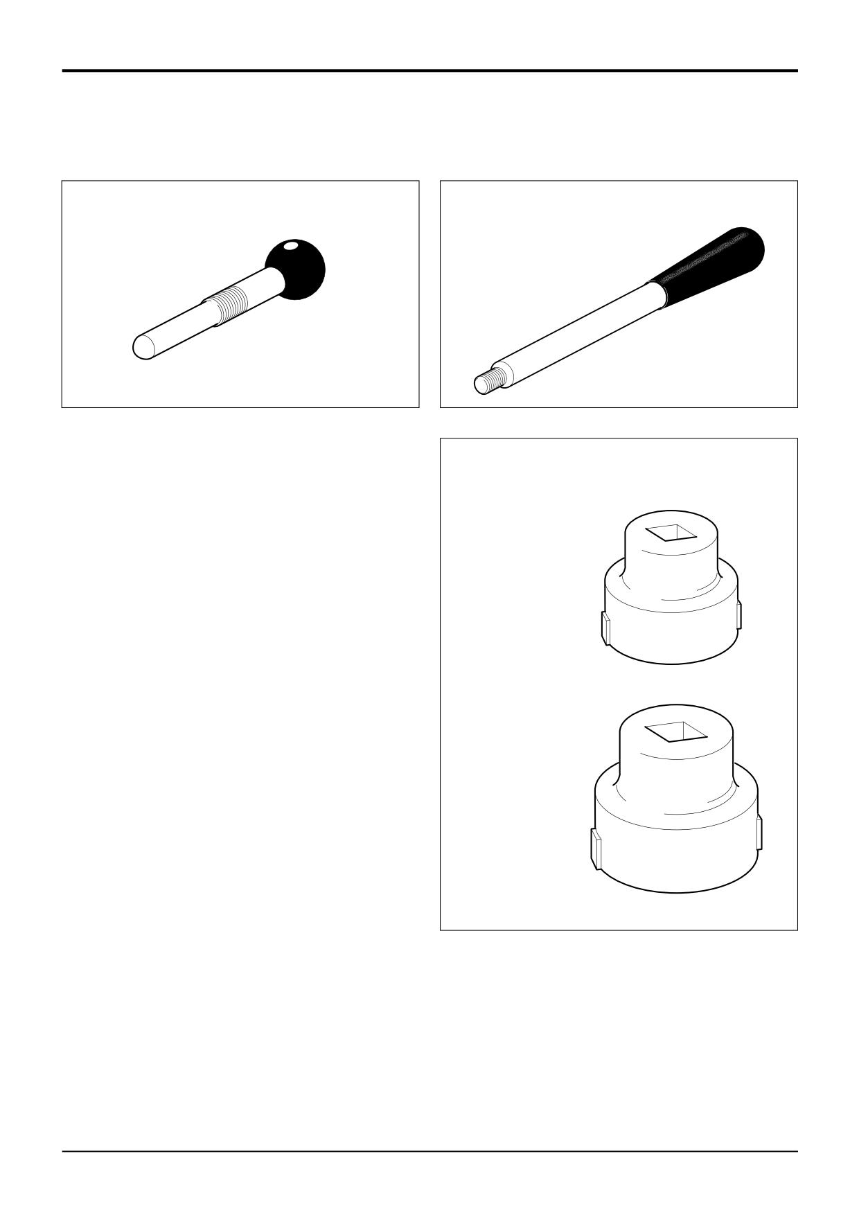
892/01077
Synchro Shuttle Gearbox - Selector
892/01078
Synchro Shuttle Gearbox - Mainshaft
Shaft Lock Screw
Adjuster
A395350
A396510
Synchro Shuttle Gearbox - Setting ring socket spanners
892/01079
(Mainshaft setting ring)
A396590
892/01080
(Layshaft setting ring)
A396600
9803/3280
Issue 1
Section 1
Transmission
Section 1
1 - 2
Service Tools
1 - 2
Service Tools (cont'd)
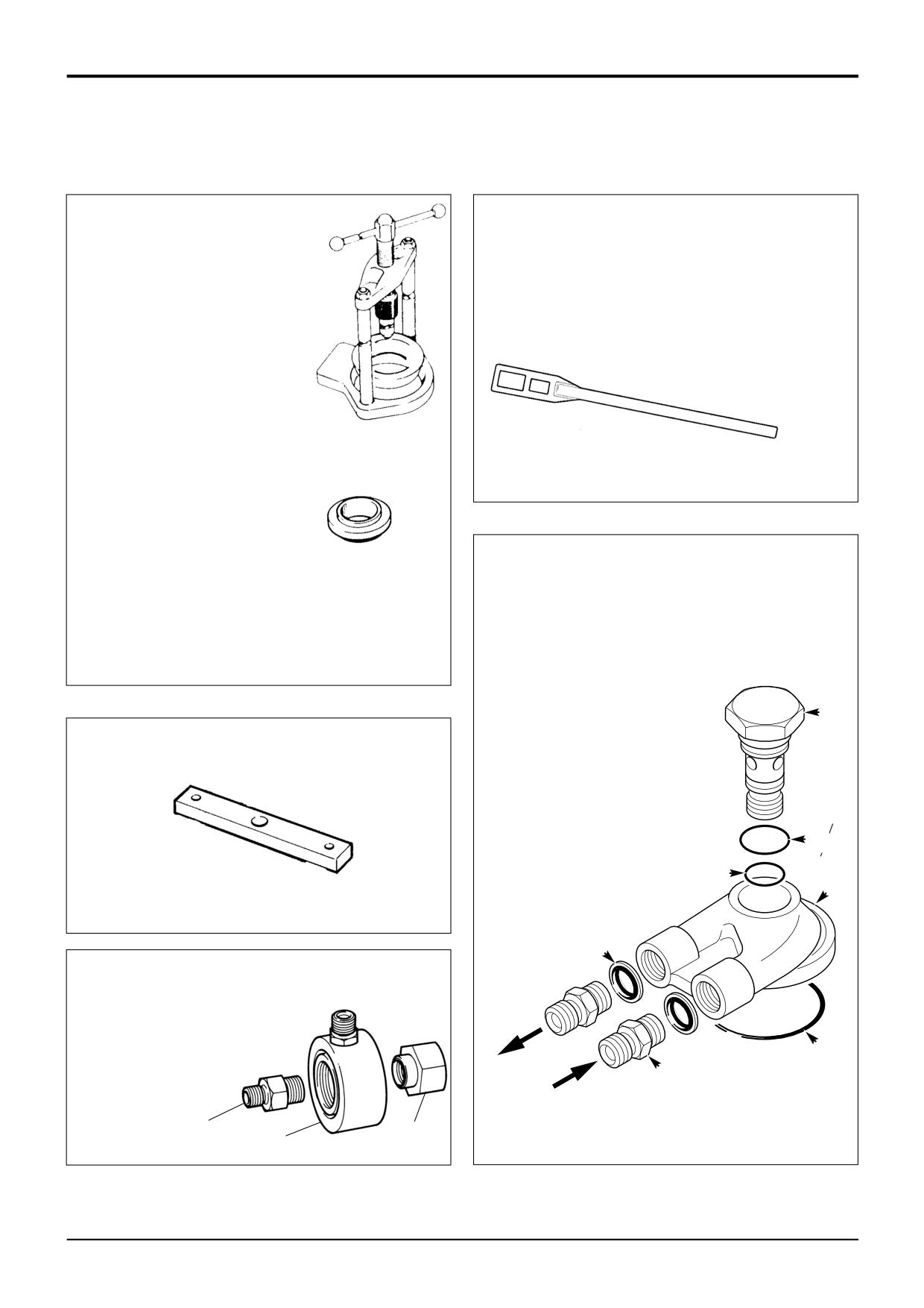
892/00179
Bearing Press (use with
appropriate adapters)
892/00812
Drive Coupling Spanner
S188200
S107750
992/07608
Bearing Adapter
992/07609
Bearing Adapter
992/07610
Bearing Adapter
992/07611
Bearing Adapter
992/07612
Bearing Adapter
992/07613
Bearing Adapter
Powershift Gearbox Flow Test Adaptor
1
460/15708 Flow Test Adapter
2
460/15707 Banjo Bolt
S188160
3
2401/0222 O-ring
4
2403/0110 O-ring
5
2403/0108 O-ring
6
1604/0004 Adapter
7
1406/0018 Sealing Washer
2
892/00922
12.2” Torque Converter Alignment Tool
4
5
1
S267260
7
A
892/00920 Flow Test Adapter
B
892/00301 Flow Test Adapter
C
892/00302 Flow Test Adapter
3
6
A313250
A
S188210
C
B
9803/3280
Issue 1
Section F
Transmission
Section F
1 - 3
Service Tools
1 - 3
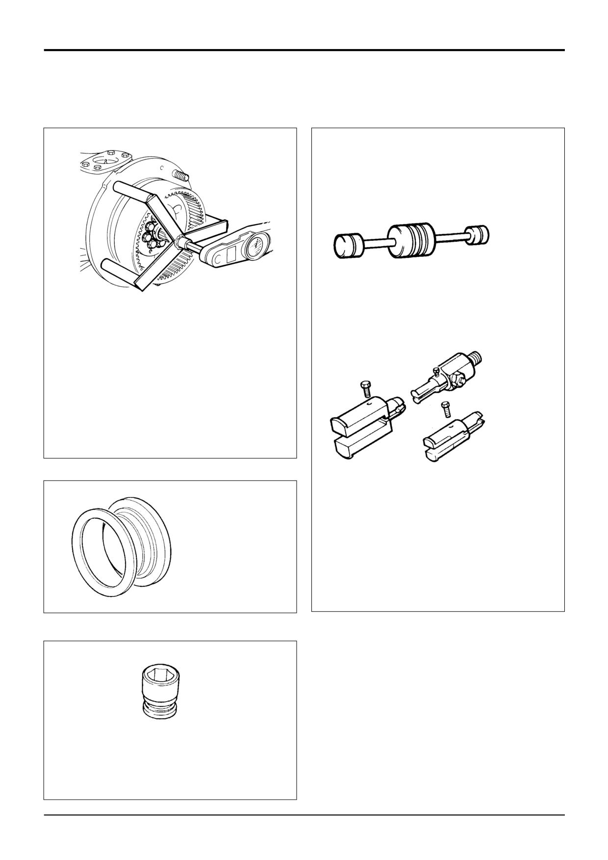
892/00224
Impulse Extractor Set for Hub Bearing Seals
S261230
S197070
Torque Measuring Tool for Wheel Hub Seals
Manufacture locally, procedures in this manual show
checking the wheel hub seal using a rolling force.
However, the torque can be measured using above
locally manufactured tool.
Bearing rolling torque is 12 to 22 Nm (9 to 16 lbf ft)
excluding seal drag. Maximum permissible including
seal drag is 40 Nm (29.5 lbf ft).
892/00225
Adapter - Impulse Extractor
Small
17mm to 25mm
892/00891
Medium 25mm to 45mm
Large
45mm to 80mm
Fitting Tool Assembly for
993/59500
Adapter - Impulse Extractor (syncro
Wheel Hub Seals
shuttle and powershift transmission)
S227760
S216290
892/00817
17 mm A/F x 3/4in. square drive
892/00818
22 mm A/F x 3/4in. square drive
892/00819
15 mm A/F x 1/2in. square drive
892/00333
19 mm A/F x 3/4in. square drive
9803/3280
Issue 1
Section F
Transmission
Section F
1 - 4
Service Tools
1 - 4
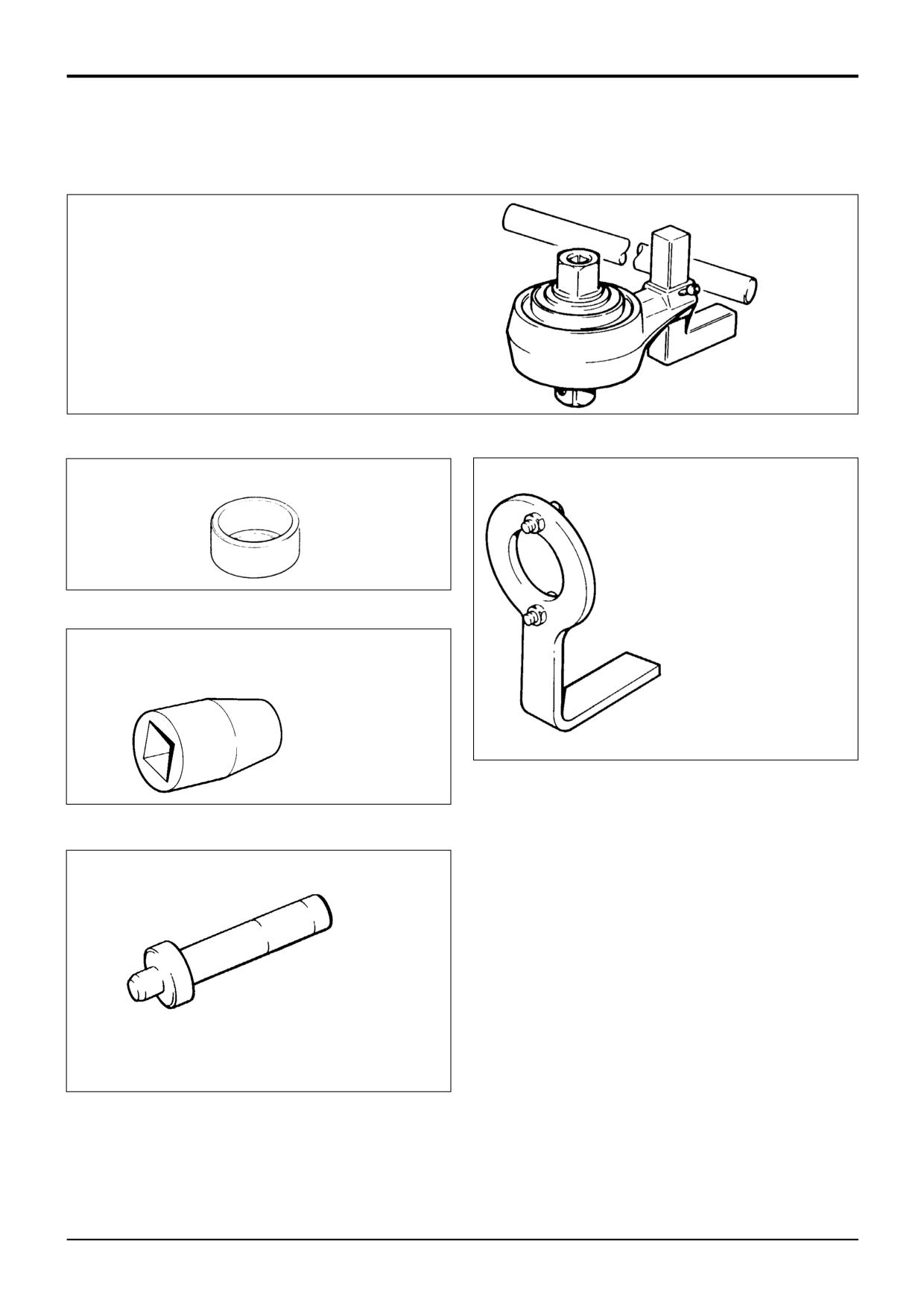
992/04000
Torque Multiplier (use in conjunction with a
torque wrench to give a
5:1 multiplication
when tightening pinion nuts)
S197030
892/00174
Measuring Cup - Pinion Head Bearing
992/04800
Flange Spanner - for locking brake disc
flange while pinion nut is slackened or
torque set
S190770
892/00822
Splined Bolt Socket for driveshafts
S197040
S197060
S216310
892/00182
Bearing Pad Driver
9803/3280
Issue 1
Section F
Transmission
Section F
1-5
Service Tools
1-5
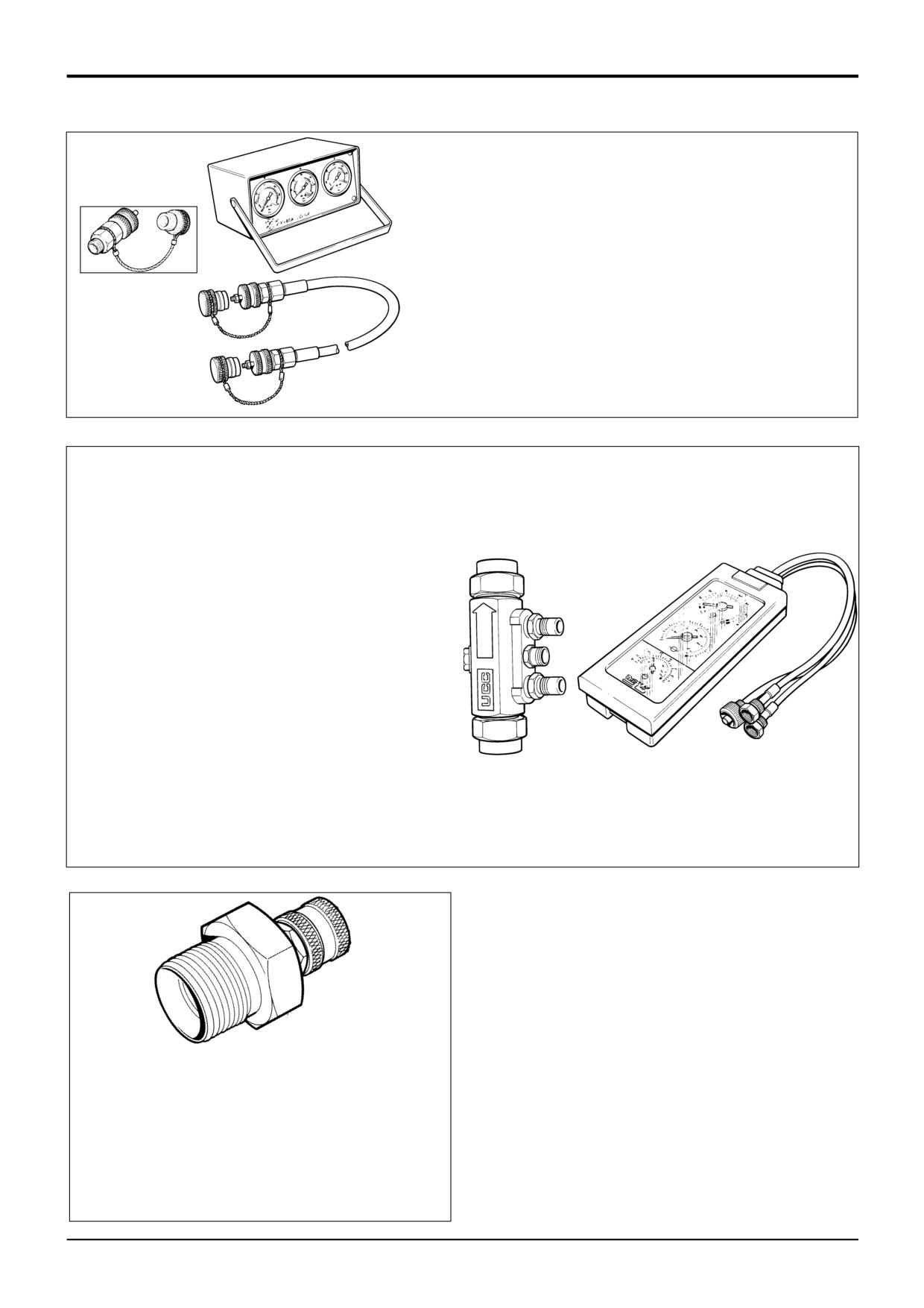
Hydraulic Circuit Pressure Test Kit (also used for main hydraulic
system tests)
892/00253
Pressure Test Kit
:892/00201
Replacement Gauge 0-20 bar (0-300 lbf/in2)
:892/00202
Replacement Gauge 0-40 bar (0-600 lbf/in2)
:892/00203
Replacement Gauge 0-400 bar (0-6000 lbf/in2)
S267300
:892/00254
Replacement Hose
993/69800
Seal Kit for 892/00254 (can also be used with
probe 892/00706)
892/00706
Test Probe
S188121
Flow Test Equipment (also used for main hydraulic system
tests)
892/00268
Flow Monitoring Unit
892/00269
Sensor Head 0 - 100 l/min (0 - 22 UK gal/min)
892/00293
Connector Pipe
892/00270
Load Valve
1406/0021
Bonded Washer
1604/0006
Adapter 3/4 in M x 3/4 in M BSP
1612/0006
Adapter 3/4 in F x 3/4 in M BSP
892/00271
Adapter 3/4 in F x 5/8 in M BSP
892/00272
Adapter 5/8 in F x 3/4 in M BSP
816/20008
Adapter 3/4 in F x 1/2 in M BSP
892/00275
Adapter 1/2 in F x 3/4 in M BSP
892/00276
Adapter 3/4 in F x 3/8 in M BSP
892/00277
Adapter 3/8 in F x 3/4 in M BSP
892/00273
Sensor Head 0 - 380 l/min
892/00294
Connector Pipe
1606/0015
Adapter 1.1/4 in M BSP x 1 in M BSP
892/00078
Connector 1 in F x 1 in F BSP
1604/0008
Adapter 1 in M x 1 in M BSP
S188151
1606/0012
Adapter 1 in M x 3/4 in M BSP
816/20013
Adapter 3/4 in F x 1 in M BSP
S316250
Test Point
1
892/00964
Test point (1/8 BSP) Powershift
2
892/00965
Test point (3/8 BSP) Powershift
3
892/00966
Test point (1/4 BSP) Synchro Shuttle
These test points can be left in position after testing.
9803/3280
Issue 1
Section F
Transmission
Section F
1-6
Service Tools
1-6
1
5
A396960
6
2
A396930
3
7
A396950
4
A396940
8, 9
A396580
9803/3280
Issue 2*
Section F
Transmission
Section F
1 - 7
Service Tools
1 - 7
Service Tools (cont'd)
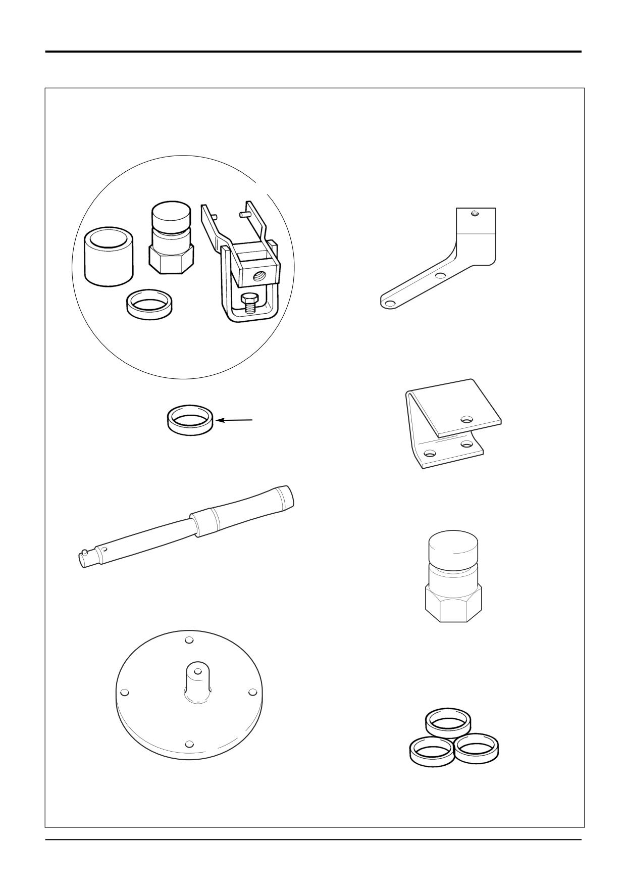
Solid Spacer Setting Kit
9
921/53400
Spacer Kit - Sychro Shuttle Gearbox,
Synchro Shuttle Gearbox, SD70, SD80
SD70, SD80 Axles
Axles
Comprises of:
1
892/00918
Setting Tool Kit
Spacer thickness mm
2
921/52627
Spacer 14.20 Service use
921/52628
12.600
3
993/70111
Breakback Torque Wrench
829/30405
12.625
4
892/01076
Support Bracket -
921/52629
12.650
Synchro Shuttle Gearbox
829/30406
12.675
921/52630
12.700
5
892/01075
Support Bracket
829/30407
12.725
PD70, SD80 Rear Axles
921/52601
12.750
6
997/11000
Support Bracket
829/30408
12.775
SD55, SD70 Front Axles
921/52602
12.800
7
998/10567
SD80 Pinion Shaft Adaptor
829/30409
12.825
921/52603
12.850
8
921/53300
Spacer Kit - SD55 Axles
829/30410
12.875
921/52604
12.900
Comprises of:
829/30411
12.925
Spacer thickness mm
921/52605
12.950
921/53322
13.550
829/30412
12.975
921/53323
13.575
921/52606
13.000
829/30413
13.025
921/53324
13.600
921/52607
13.050
921/53325
13.625
829/30414
13.075
921/53301
13.650
921/52608
13.100
921/53302
13.675
829/30415
13.125
921/53303
13.700
921/52609
13.150
921/53304
13.725
829/30416
13.175
921/53305
13.750
921/52610
13.200
921/53306
13.775
829/30417
13.225
921/53307
13.800
921/52611
13.250
921/53308
13.825
921/53424
13.275
921/53309
13.850
921/53425
13.300
921/53310
13.875
921/53426
13.325
921/53311
13.900
921/53427
13.350
921/53428
13.375
921/53312
13.925
921/53401
13.400
921/53313
13.950
921/53402
13.425
921/53314
13.975
921/53403
13.450
921/53315
14.000
921/53404
13.475
921/53316
14.025
921/53405
13.500
921/53317
14.050
921/53406
13.525
921/53318
14.075
921/53407
13.550
921/53319
14.100
921/53408
13.575
921/53320
14.125
921/53409
13.600
921/53321
14.150
921/53410
13.625
921/53411
13.650
921/53412
13.675
921/53413
13.700
921/53414
13.725
921/53415
13.750
921/53416
13.775
921/53417
13.800
921/53418
13.825
921/53419
13.850
921/53420
13.875
921/53421
13.900
921/53422
13.925
921/53423
13.950
921/52626
14.000
Note: After using a spacer, obtain a replacement to keep
the set complete
9803/3280
Issue 1
Section F
Transmission
Section F
1 - 8
Service Tools
1 - 8
Service Tools (cont'd)
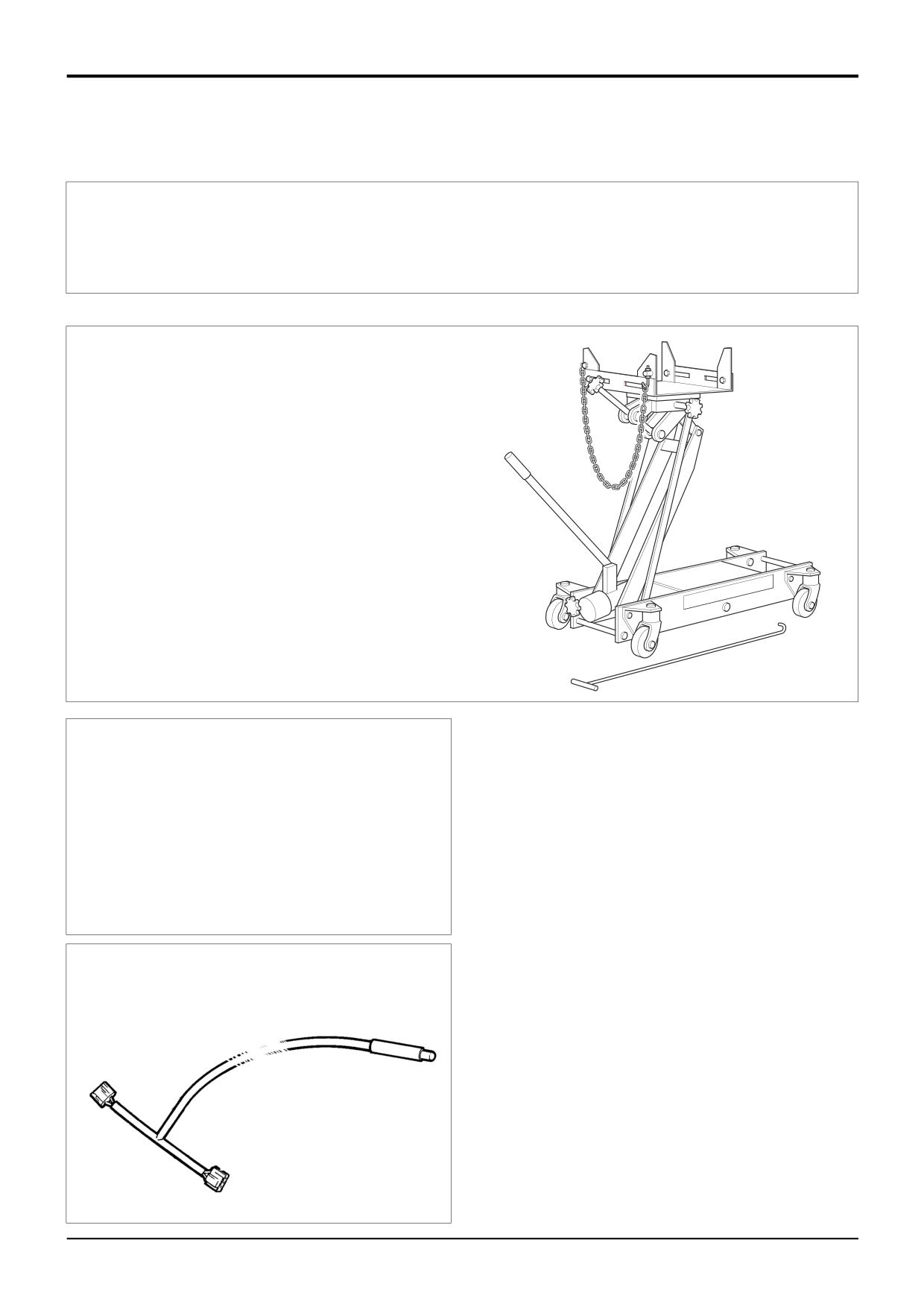
892/01083
Powershift - Assembly tool,
transfer gear
892/01084
Powershift - Transfer gear, bearing
assembly
892/01085
Powershift - Seal fitting tool
*
892/01094 Transmission Jack
When removing the Powershift gearbox use of a special
transmission jack is strongly recommended. This jack
can also be used when removing Synchro Shuttle
gearboxes.
Note that the jack must be used with special support
plates, see the facing page for details.
A402680
*
823/10420
Thrust Washer Kit - Powershift
gearbox - Layshaft clutch
Comprises of:
Washer thickness mm
823/10421
4.3
823/10422
4.4
823/10423
4.5
823/10424
4.6
823/10425
4.7
823/10426
4.8
*
892/01096
Speed Sensor Test Harness -
Powershift Gearbox
9803/3280
Issue 3*
Section F
Transmission
Section F
1 - 9
Service Tools
1 - 9
Service Tools (cont'd)
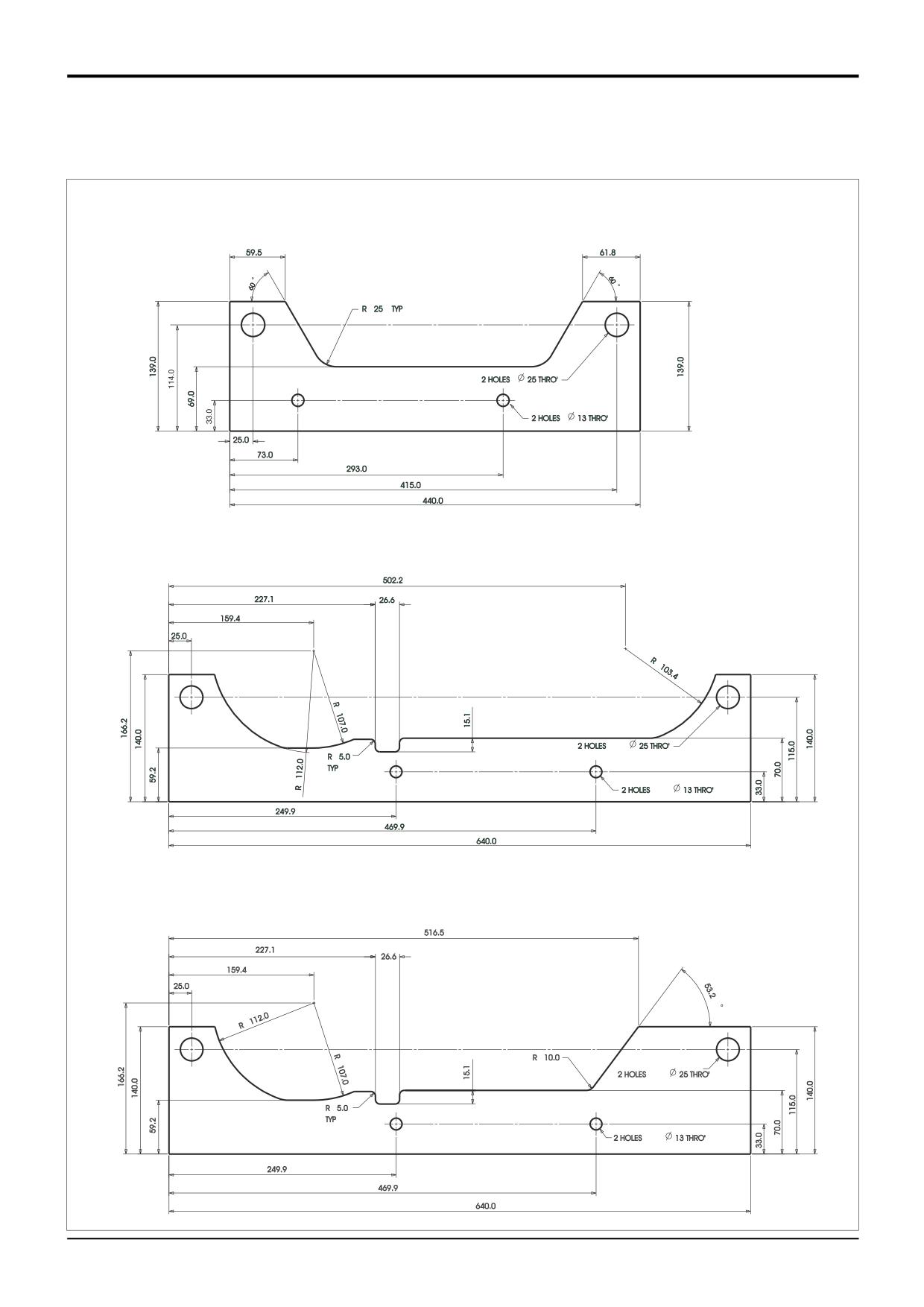
* Powershift gearbox - support plates for use with
hydraulic jack. Plates should be locally manufactured
from 5 mm thick mild steel plate.
Rear plate - 4 speed
and 6 speed.
Front plate - 6 speed.
Front plate - 4 speed.
9803/3280
Issue 2*
Section F
Transmission
Section F
1 - 10
Service Tools
1 - 10
Service Tools (cont'd)
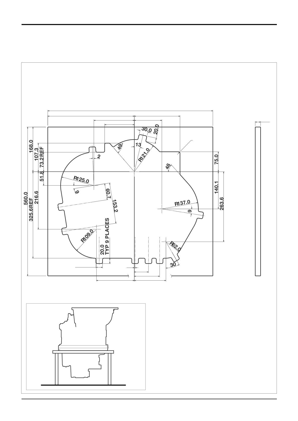
892/01082
Powershift - Assembly Cradle
Note: Support legs will also be required. These must be
locally manufactured so that the gearbox can be
supported as shown at A.
620.0
325.0
171.6
151.9
103.4
20.0
111.6
R
5.0
TYP
25.0
==
2.9
53.2
TYP 9 PLACES
95.0
142.3
118.7
A402690
A
9803/3280
Issue 2*
Section F
Transmission
Section F
1 - 11
Service Tools
1 - 11
Service Tools (cont'd)
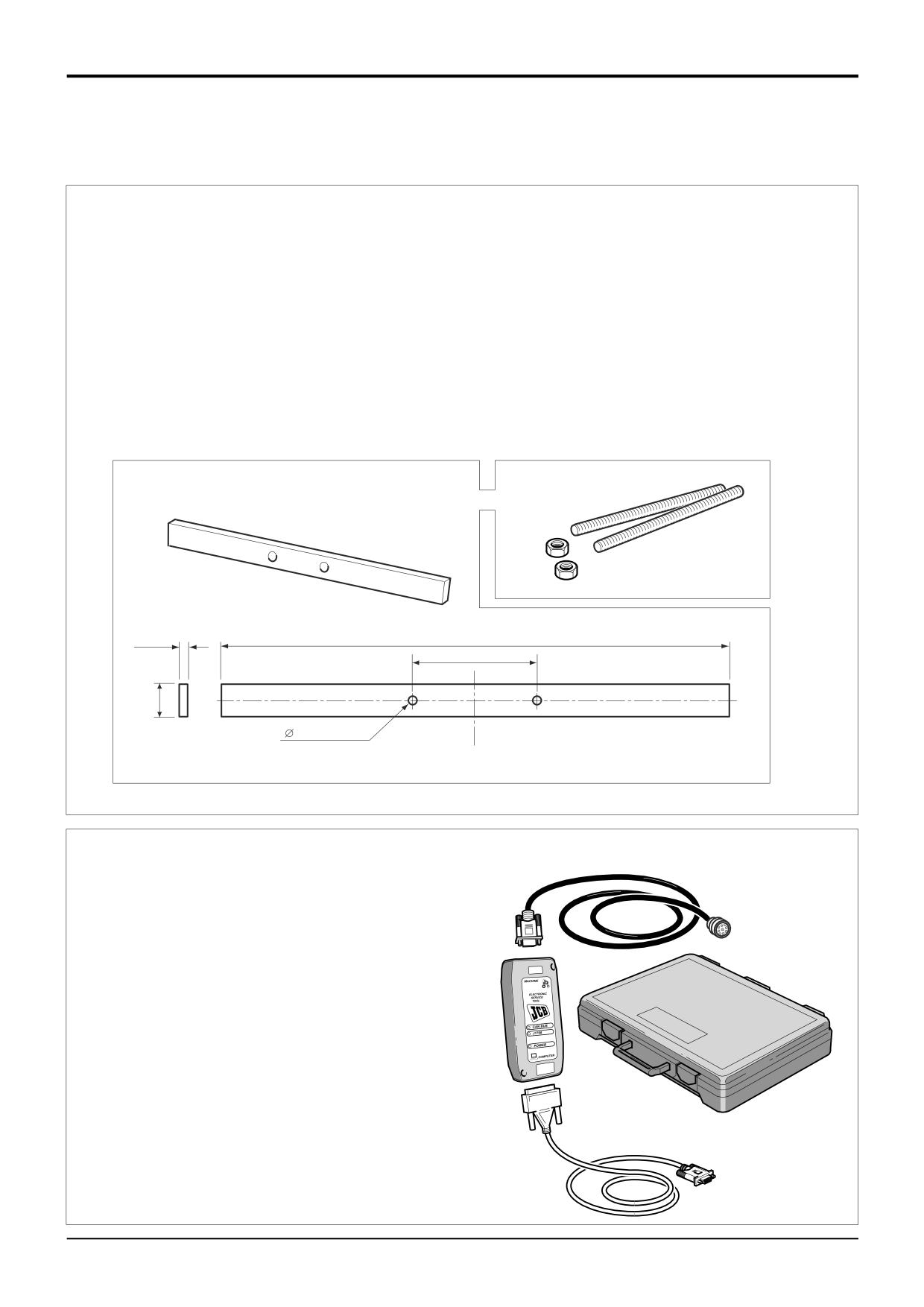
Powershift Gearbox - hydraulic pump removal tools
The tools detailed below enable the pump to be removed
with the torque converter housing in place.
1
Reaction bar. Locally manufacture from mild steel bar.
Drill the 2 holes through the bar as shown.
2
2 off lengths of M10 x 1.5 threaded rod 250 mm (10 in)
long.
3
2 off M10 x 1.5 nuts.
A set of M10 x 1.5 taps will also be required.
1
2
3
12 mm
500 mm
121.5 mm
32 mm
11.0 mm
A406000
Powershift Gearbox - 6 Speed (ShiftMaster)
Electronic Service Tool Kit
3
892/01033 Kit comprises:
1
Data Link Adaptor (DLA), enables data exchange
between the machine ECU (Electronic Control Unit) and
1
a laptop PC loaded with the applicable ShiftMaster
diagnostics software.
4
2
Interconnecting cable, DLA to laptop PC. Several cables
are included to enable compatibility with different PC
port types.
3
Interconnecting cable, DLA to machine ECU diagnostics
socket.
4
Kit carrying case.
2
A406130
9803/3280
Issue 1
Section F
Transmission
Section F
2 - 1
Technical Data
2 - 1
Tyre Pressures
Note: If the tyres fitted to your machine are not listed, then contact JCB for advice, DO NOT guess tyre pressures.
Front Wheels
AWS/4WD MACHINES
Item Size x Ply
Type
Make
Remarks
Pressure
bar
lbf/in2
1
16.9x24x12
IND
ARMSTRONG
TUBELESS
2.6
38
2
16.9x24x12
IND
GOODYEAR
TUBELESS
2.6
38
3
15.5x25
XTLA
MICHELIN
TUBELESS
2.5
36
4
16.9x28x12
IND
ARMSTRONG
TUBELESS
2.6
38
5
16.9x28x12
IND
GOODYEAR
TUBELESS
2.6
38
6
16.9x28x10
IND
GOODYEAR
TUBELESS
2.2
32
7
16.9x28
XM27
MICHELIN
TUBELESS
2.7
39
8
16.9x28x14
IND
NOKIA
TUBE
2.6
38
9
16.9x24x12
IND
GOODYEAR
TUBELESS
2.6
38
10
16.9x28x12
TRAC
OLYMPIC
TUBELESS
2.6
38
11
16.9x28x12
IND
OLYMPIC
TUBE
2.6
38
12
14.9x24x12
IND
GOODYEAR
TUBELESS
2.75
40
13
16.9x28
IND
GOODYEAR
TUBELESS
2.5
36
2WS/2WD MACHINES
21
11.0x16x12
RIB
ARMSTRONG
TUBELESS
4.4
64
22
11.0x16x12
RIB
GOODYEAR
TUBELESS
4.2
61
23
11Lx16x12
IND
ARMSTRONG
TUBELESS
4.4
64
24
10.5x18x10
IND
FIRESTONE
TUBELESS
3.8
55
25
12.0x18x12
IND
FIRESTONE
TUBELESS
3.5
51
2WS/4WD MACHINES
31
14x17.5x10
IND
ARMSTRONG
TUBELESS
3.8
55
32
14x17.5x10
IND
GOODYEAR
TUBELESS
3.8
55
34
12.0x18x12
IND
FIRESTONE
TUBELESS
3.5
51
35
12.0x18x12
IND
OLYMPIC
TUBELESS
4.25
62
36
335 x18
XM27
MICHELIN
TUBELESS
3.5
51
37
12.5x18x10
IND
GOODYEAR
TUBELESS
4.25
62
38
335 x20
XM27
MICHELIN
TUBE
3.0
43.5
39
340 x18
IND
GOODYEAR
TUBELESS
3.2
46
Items 4, 5, 6, 7,8, 9, 10, 11, 13, 38 must have steering lock restriction stops fitted.
9803/3280
Issue 1
Section F
Transmission
Section F
2 - 2
Technical Data
2 - 2
Tyre Pressures
Note: If the tyres fitted to your machine are not listed, then contact JCB for advice, DO NOT guess tyre pressures.
Rear Wheels
AWS MACHINES
Item Size x Ply
Type
Make
Remarks
Pressure
bar
lbf/in2
1
16.9x24x12
IND
ARMSTRONG
TUBELESS
2.6
38
2
16.9x24x12
IND
GOODYEAR
TUBELESS
2.6
38
3
15.5x25
XTLA
MICHELIN
TUBELESS
2.5
36
4
16.9x28x12
IND
ARMSTRONG
TUBELESS
2.6
38
5
16.9x28x12
IND
GOODYEAR
TUBELESS
2.6
38
6
16.9x28x10
IND
GOODYEAR
TUBELESS
2.2
32
7
16.9x28
XM27
MICHELIN
TUBELESS
2.7
39
8
16.9x28x14
IND
NOKIA
TUBE
2.6
38
9
16.9x24x12
IND
GOODYEAR
TUBELESS
2.6
38
10
16.9x28x12
TRAC
OLYMPIC
TUBELESS
2.6
38
11
16.9x28x12
IND
OLYMPIC
TUBE
2.6
38
12
14.9x24x12
IND
GOODYEAR
TUBELESS
2.75
40
13
16.9x28
IND
GOODYEAR
TUBELESS
2.5
36
2WS MACHINES
21
16.9x24x10
IND
ARMSTR0NG
TUBELESS
2.2
32
22
16.9x24x12
IND
GOOOYEAR
TUBELESS
2.2
32
23
19.5x24x10
IND
ARMSTRONG
TUBELESS
1.9
28
24
19.5x24x12
IND
ARMSTRONG
TUBELESS
2.3
33
25
21L x24x12
IND
GOODYEAR
TUBELESS
2.2
32
26
18.4x26x12
TRAC
GOODYEAR
TUBELESS
2.5
36
27
18.4x26x12
TRAC
OLYMPIC
TUBELESS
2.4
35
28
18.4x26x12
IND
GOODYEAR
TUBELESS
2.0
29
29
16.9x28x12
TRAC
OLYMPIC
TUBELESS
2.2
32
30
16.9x28x12
TRAC
FIRESTONE
TUBE
2.2
32
31
16.9x28x12
IND
GOODYEAR
TUBELESS
2.2
32
32
16.9x28
XM27
MICHELIN
TUBELESS
2.5
36
33
18.4x30x14
IND
GOODYEAR
TUBE
2.0
29
34
16.9x28
IND
GOODYEAR
TUBELESS
2.5
36
Note: 12 ply tyres must be fitted on rear wheels when any backhoe attachment is used. For the correct pressure see the table
above.
Items 4, 5, 6, 7,8, 9, 10, 11, 13 must have steering lock restriction stops fitted.
9803/3280
Issue 1
Section F
Transmission
Section F
3 - 1
Technical Data
3 - 1
Front Axle
Note: It is essential that the correct ratio axle in relationship to the gearbox ratio is fitted to the machine. Do not fit a new axle
with a different ratio to the axle being replaced.
ALL WHEEL STEER MACHINES
Type
JCB spiral bevel input with epicyclic hub reduction
Designation
SD70
Installation
Centre pivot
Weight
(dry, with no steer rams and without wheels)
385 kg (850 lbs) approximately
Overall Gear Ratio
24.975:1
Crownwheel and Pinion Ratio
4.625:1
Number of Teeth
Crownwheel
37
Pinion
8
Hub Reduction
5.4:1
Input Type
Yoke
Oscillation
± 5°
Toe - in
0°
Castor Angle
0°
Camber Angle
1°
King - pin inclination
0°
2 WHEEL STEER MACHINES (4 Wheel Drive)
Type
JCB spiral bevel input with epicyclic hub reduction
Designation
SD55
Installation
Centre pivot
Weight
(dry, with no steer rams and without wheels)
330 kg (728 lbs) approximately
Hub Reduction
5.4:1
Input Type
Yoke
Oscillation
± 5°
Toe - in
0 °
Castor Angle
0 °
Camber Angle
1 °
King - pin inclination
0 °
Ratios
OPTION 1
OPTION 2
Overall
16.2:1
19.2:1
Crownwheel and Pinion
3:1
3.556:1
Number of Teeth
Crownwheel
33
32
Pinion
11
9
2 WHEEL STEER MACHINES (2 Wheel Drive)
Type
JCB centre oscillation, non-driven
Installation
Centre pivot
Weight
(dry, with steer ram and without wheels)
239 kg (525 lbs) approximately
Oscillation
± 5°
Toe - in
0°
Castor Angle
0°
Camber Angle
3 ° positive
9803/3280
Issue 1
Section F
Transmission
Section F
3 - 2
Technical Data
3 - 2
Rear Axle
Note: It is essential that the correct ratio axle in relationship to the gearbox ratio is fitted to the machine. Do not fit a new axle
with a different ratio to the axle being replaced.
ALL WHEEL STEER MACHINES
Type
3 piece, JCB spiral bevel input with epicyclic hub reduction and inboard
braking. Pinion mounted park brake disc.
Designation
SD80
Installation
Rigid pad mount
Number of steer rams
1 (Double rod)
Weight (dry, with no steer rams
410 kg (904 lbs) approx.
and without wheels)
Half (Axle) Shaft Braking/Type
5 friction plate, 6 counter plate (each half shaft)
Input Type
Yoke
Oscillation
± 5°
Toe - in
0 °
Castor Angle
0 °
Camber Angle
1 °
King - pin inclination
0 °
Hub Reduction
5.4:1
Ratios
OPTION 1
OPTION 2
OPTION 3
Overall
15.78:1
18.16:1
13.7:1
Crownwheel and Pinion
2.923:1
3.363:1
2.538:1
Number of Teeth
Crownwheel
38
37
33
Pinion
13
11
13
2 WHEEL STEER MACHINES
Type
3 piece, JCB spiral bevel input with epicyclic hub reduction and inboard
braking. Pinion mounted park brake disc.
Designation
PD70
Installation
Rigid pad mount
Weight (dry and without wheels)
386 kg (851 lbs) approx.
Half (Axle) Shaft Braking/Type
5 friction plate, 6 counter plate (each half shaft)
Input Type
Yoke
Hub Reduction
5.4:1
Ratios
OPTION 1
OPTION 2
OPTION 3
Overall
15.78:1
18.16:1
13.7:1
Crownwheel and Pinion
2.923:1
3.363:1
2.538:1
Number of Teeth
Crownwheel
38
37
33
Pinion
13
11
13
9803/3280
Issue 1
Section F
Transmission
Section F
4-1
Technical Data
4-1
Synchro Shuttle Gearbox
Description
Combined torque converter, reverser, and gearbox unit.
Synchromesh manual gear selection. Electro hydraulic
selection of forward and reverse.
Designation
SS700 (4 wheel drive)
Weight (dry)
2WD
* 170 kg (375 lb)
4WD
* 200 kg (441 lb)
Gear Ratios
Std Ratio
Low Ratio
1st
5.56:1
6.56:1
2nd
3.45:1
4.06:1
3rd
1.83:1
1.90:1
4th
1.00:1
1.00:1
Torque Converter
Torque Converter Dia.
310 mm (12.2 in.)
Torque Converter Identification
04/600580
04/600581
Torque Multiplication at Stall
2.52:1
3.01:1
Converter Pressures (in neutral)
bar
kgf/cm2
lbf/in2
Converter In at 50 deg.C
1000 rev/min
1.5 - 2.5
1.5 - 2.5
22 - 36
2000 rev/min
5.3 - 6.7
5.4 - 6.8
77 - 97
Converter In at 100 deg.C
1000 rev/min
0.5 - 1.3
0.5 - 1.3
7 - 19
2000 rev/min
4.1 - 4.9
4.2 - 5.0
59 - 71
Converter Out at 50 deg.C
1000 rev/min
0.8 - 1.6
0.8 - 1.6
12 - 23
2000 rev/min
3.0 - 4.0
3.1 - 4.1
43 - 58
Converter Out at 100 deg.C
1000 rev/min
0.3 - 0.9
0.3 - 0.6
4-9
2000 rev/min
2.1 - 2.9
2.1 - 3.0
30 - 42
Lubrication Pressures (in neutral)
bar
kgf/cm2
lbf/in2
At 50 deg.C
1000 rev/min
0.3 - 0.9
0.3 - 0.9
4 - 13
2000 rev/min
1.8 - 2.4
1.8 - 2.4
26 - 35
At 100 deg.C
1000 rev/min
0.1 - 0.3
0.1 - 0.3
1-4
2000 rev/min
1.3 - 2.1
1.3 - 2.1
19 - 30
Main Line Pressure (in neutral) †
bar
kgf/cm2
lbf/in2
At 50 deg. C
1000 rev/min
11.0 - 13.0
11.2 - 13.3
159 - 188
2000 rev/min
13.0 - 15.6
13.3 - 16.0
188 - 226
At 100 deg.C
1000 rev/min
10.2 - 12.2
10.4 - 12.4
148 - 177
2000 rev/min
11.4 - 14.0
11.8 - 14.3
165 - 203
Clutch Pressures †
All clutch pressures should be the same as Mainline Pressure to within 0.7 bar (10
lbf/in2)
Flow Rates (in neutral)
L/min
US gal/min
UK gal/min
Cooler at 50 deg.C
1000 rev/min
7.7 - 11.0
2.0 - 2.9
1.7 - 2.4
2000 rev/min
13.9 - 20.0
3.6 - 5.3
3.0 - 4.4
Cooler at 100 deg.C
1000 rev/min
5.2 - 8.2
1.1 - 2.2
1.1 - 1.8
2000 rev/min
14.5 - 17.5
3.8 - 4.6
3.2 - 3.8
Pump at 50 deg.C
1000 rev/min
11.5 - 15.5
3.0 - 4.1
2.5 - 3.4
2000 rev/min
24.0 - 33.0
6.7 - 8.8
5.3 - 7.3
9803/3280
Issue 3*