JCB 3CX, 4CX, 214e, 214, 215, 217 & VARIANTS Backhoe Loader. Service Manual - page 23
Section F
Transmission
Section F
20 - 1
Basic Operation
20 - 1
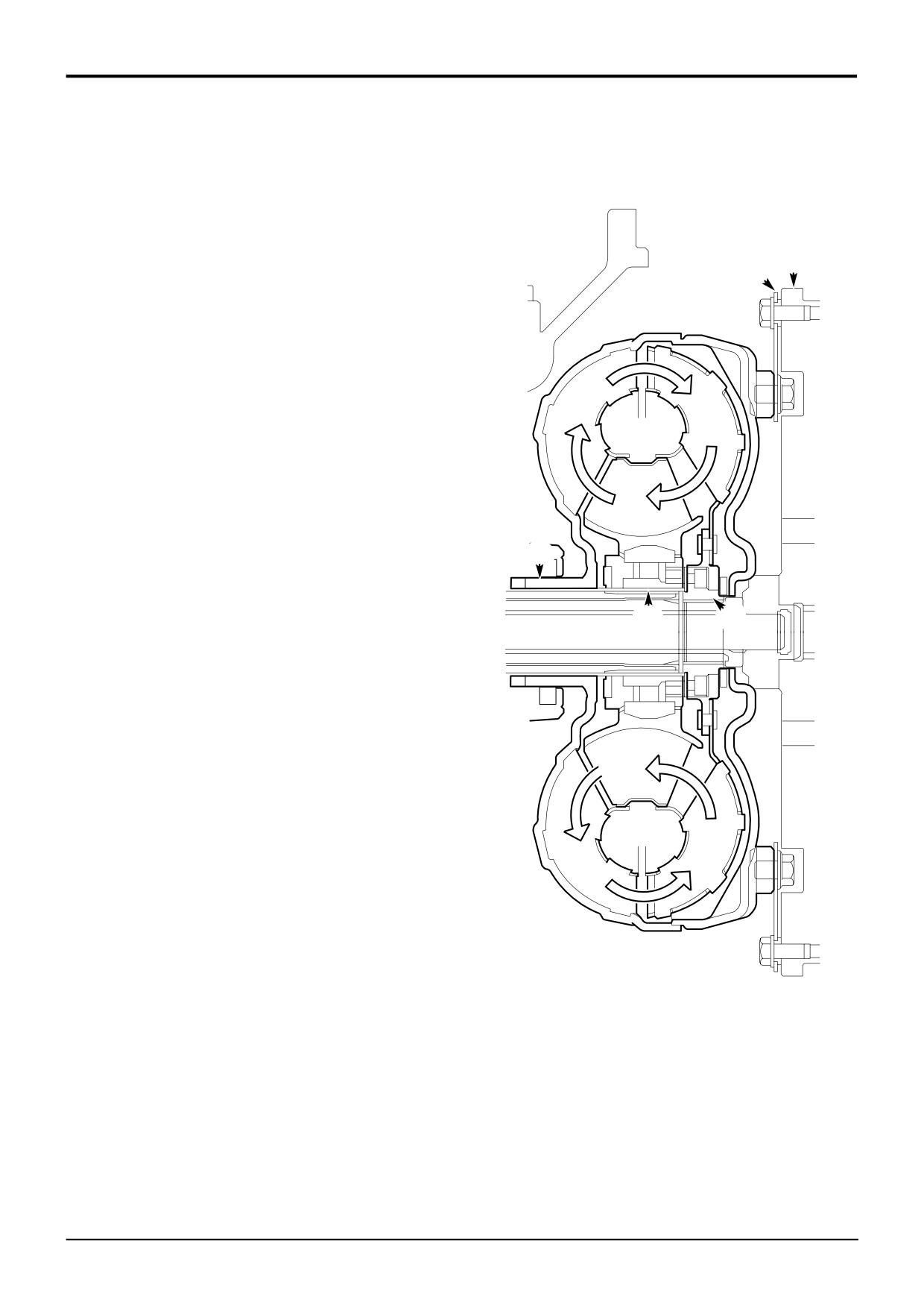
Torque Converter
Component Identification
A Impeller
B Turbine
C Reaction member
D Drive plate
E
D
E
Engine flywheel
F
Drive to gearbox input shaft
G
Spline location for reaction member
H
Direct drive from the engine to the gearbox oil pump
J
Direction of oil flow
Principle of Operation
A
B
The torque converter is similar to a fluid coupling, which
utilises the centrifugal force exerted in the transmission oil to
transmit power from the engine to the gearbox. It multiplies
the torque from the engine and functions as a combined
clutch and infinitely variable reduction gearbox
C
The torque converter is enclosed in a casing and consists of
three basic parts, the impeller A, reaction member C, and
turbine B.
H
Impeller A is driven by the engine.
G
F
Reaction member C does not rotate. Its hub engages with a
splined tube on the gearbox oil pump and is held stationary.
Turbine B is engaged with the splined end of the gearbox
input shaft.
The impeller A, driven by the engine, forms one set of
shaped blades, it can be likened to a centrifugal pump
imparting energy to the transmission oil. This energy is
J
transferred to another set of shaped blades, which form the
turbine B The turbine is connected to the gearbox and
converts the energy back to a mechanical torque.
When the impeller A is rotating faster than the turbine B, the
fixed reaction member C causes some of the energy in the
oil to be transferred back to the impeller A. This has the
effect of multiplying the torque available.
When the impeller A (input) is running much faster than the
turbine B (output) there is a substantial circulation of
transmission oil around the blades. The oil circulation is
maximum when the turbine (output) is stalled, and is almost
zero when the impeller and turbine speeds are equal i.e. the
A401340
ratio is near 1:1. If the turbine (output) is stalled whilst the
impeller (input) is revolving, all the power is dissipated as
heat.
Because of the absence of a direct mechanical connection
between the engine and the gearbox therefore, the flexibility
of the torque converter drive greatly reduces wear on the
transmission, absorbing shocks and torsional vibration from
the engine. The engine cannot be stalled due to overload, as
the fluid coupling slips.
9803/3280
Issue 1
Section F
Transmission
Section F
25 - 1
Systems Description
25 - 1
A
B
C
E
D
F
G
H
J
9803/3280
Issue 1
Section F
Transmission
Section F
25 - 2
Systems Description
25 - 2
Syncro Shuttle Gearbox
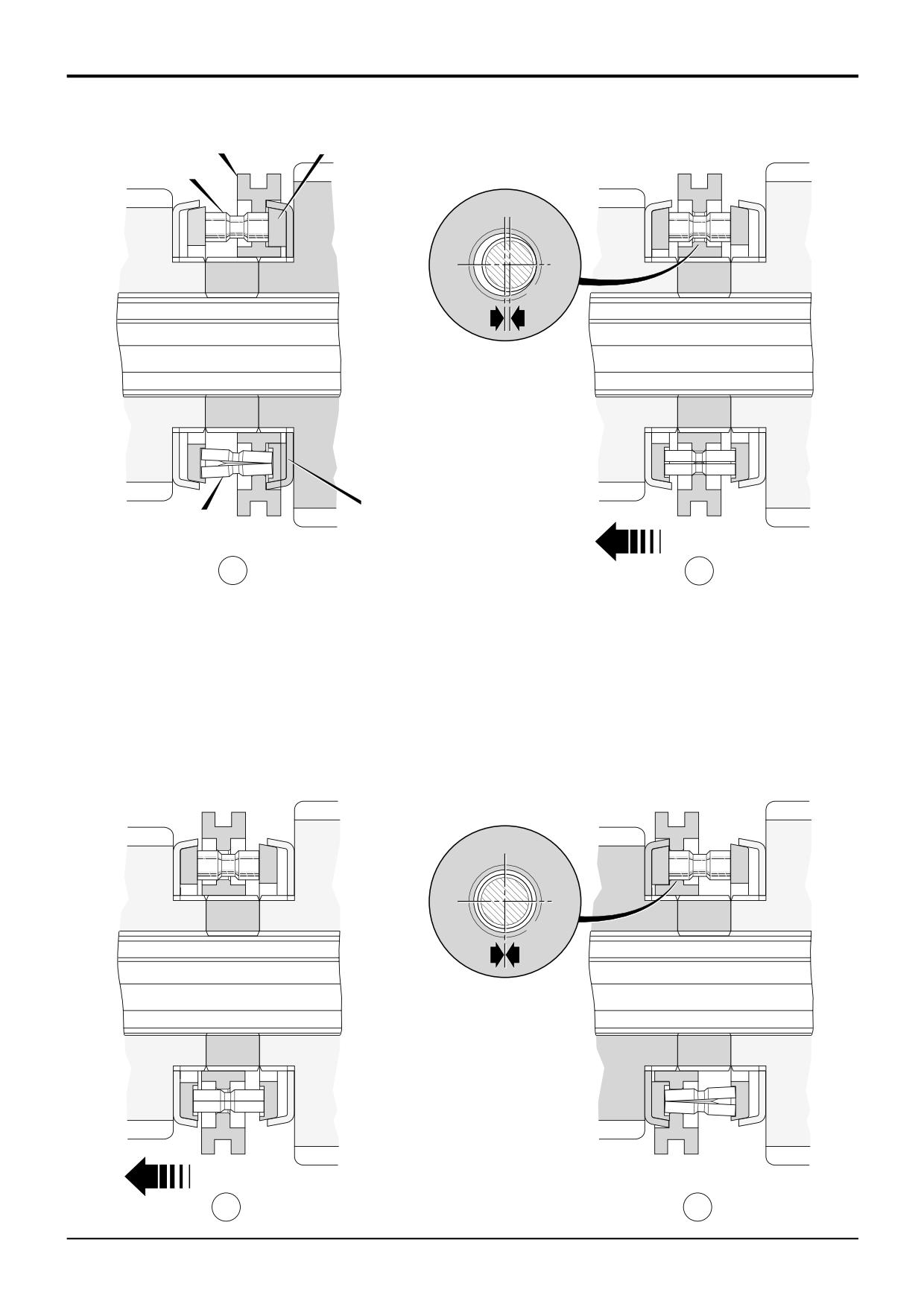
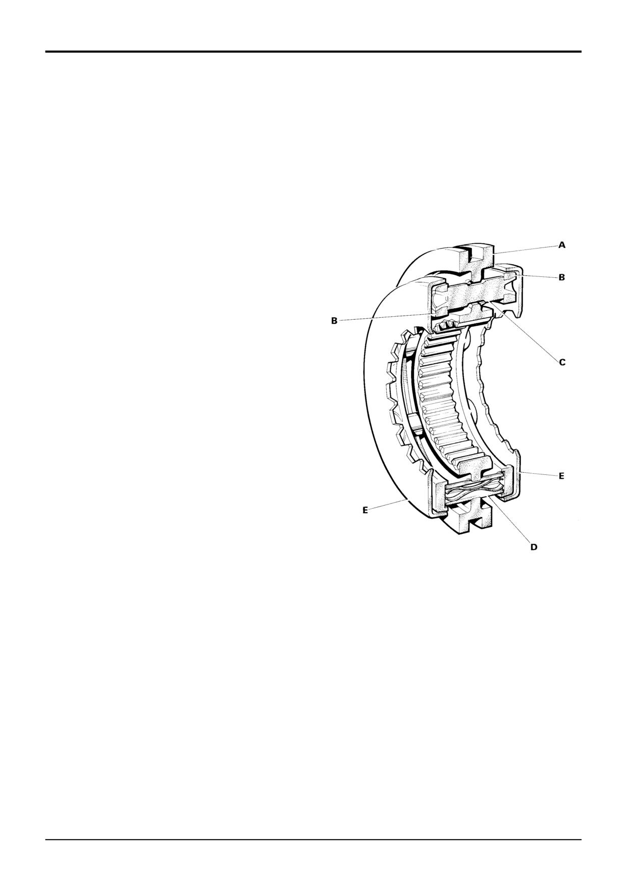
Synchromesh (Blocking Pin Type)
The gearbox is fitted with 'Blocking Pin' synchromesh,
As the speeds are synchronised the radial load on the
comprising the following parts.
blocker pin and the syncro hub is reduced. This allows the
syncro hub to slide freely along the blocker pin and engage
SYNCRO HUB (A) controls the operation of the
its dog teeth with second gear, see diagram J.
synchromesh unit and gear selection, the selector fork fitting
into the outer groove. Internal dog teeth link the selected
gear to the drive shaft. Through the syncro hub centre are
two sets of holes for the blocker pins (C) and the split
energiser pins (D), spaced alternately.
SYNCRO RINGS (B) are rigidly joined by the blocker pins,
with the split energiser pins held, in counterbores, between
the two syncro rings.
BLOCKER PINS (C) have a narrow neck in the centre,
against which the syncro hub transmits radial drive during
gear changes. The edges of the blocker pin neck and their
mating syncro hub holes are designed so that, as the radial
loads are reduced, the syncro hub can slide over the
shoulder of the blocker pin.
SPLIT ENERGISER PINS (D) take the initial axial load of the
syncro hub on the shoulder of the split energiser pin neck.
As the axial load reaches approximately 400 N (40.8 kg; 90
lb) the internal springs allow the split energiser pin to
collapse and the syncro hub to move axially.
SYNCRO CUPS (E) take the frictional drive from the syncro
ring on their inner faces. The syncro cups are splined to
drive their respective gears whilst synchronisation is taking
place.
SYNCHROMESH - OPERATION
Diagram F shows the gearbox with first gear engaged.
Syncro ring B is in contact with syncro cup E and the syncro
hub dog teeth are linking first gear to the shaft gear. In this
position the split energiser pins D are 'collapsed'.
When selecting second gear the syncro hub A slides along
the split energiser pins until the pin recess and the syncro
hub flange are in line. At this point the split energiser pins
open and the syncro rings are moved by the syncro hub
pushing on the split energiser pin shoulder.
Initial contact between the syncro ring and the syncro cup
starts to synchronise the speed of the shaft and second
gear. The rotational force of the syncro ring is taken by the
blocker pin against the edge of the syncro hub hole, as at G.
As the axial load on the syncro hub increases, the split
energiser pin 'collapses' and the conical faces of the
blocking pin and syncro hub hole come into contact, as at
H.
Further increases in the axial loads increase the frictional
grip of the syncro ring and the syncro cup, causing the shaft
and gear speeds to synchronise.
9803/3280
Issue 1
Syncro Shuttle Gearbox
Forward/Reverse Clutch Operation
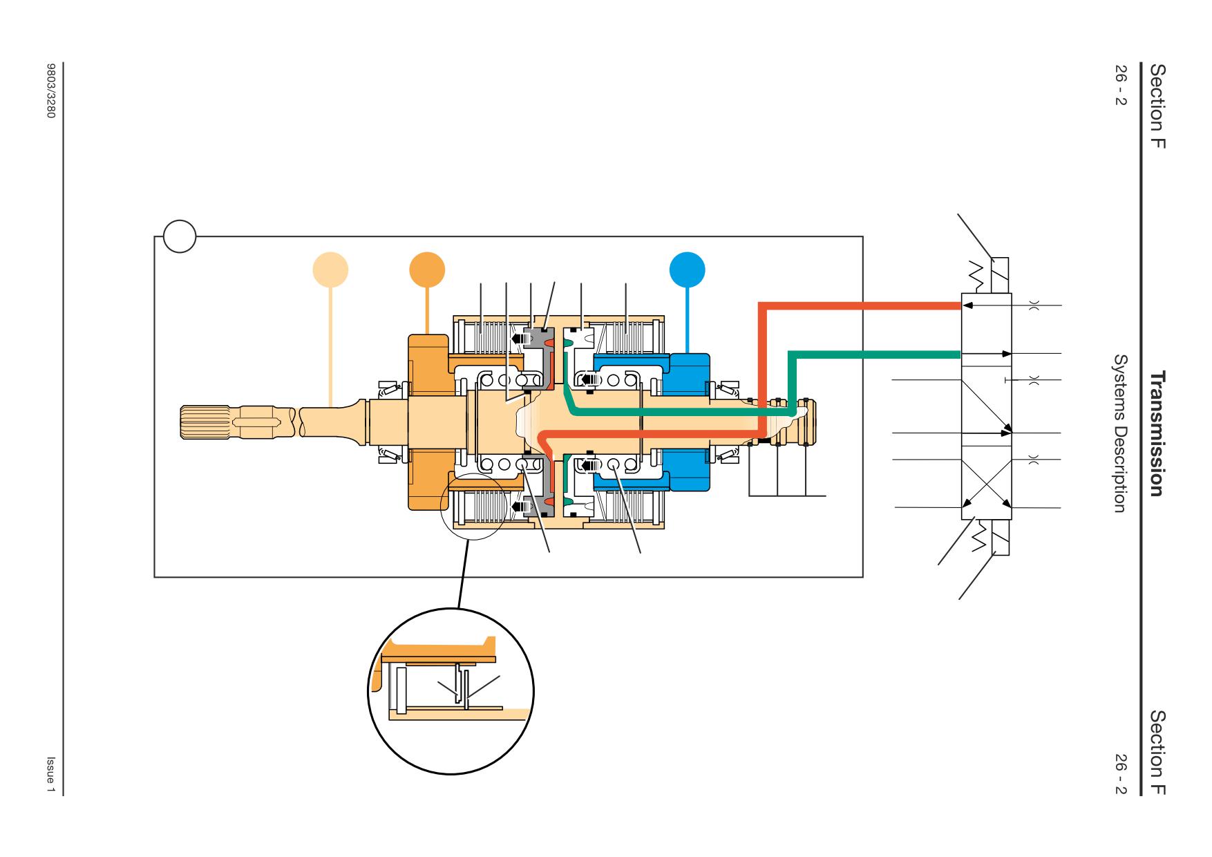
The forward/reverse clutch unit 1 transfers drive from the
input shaft A3 to either gear G1 or gear G2 depending on
which of the two clutches (A1 or A2) is engaged, giving
forward or reverse drive. When neither clutch is engaged,
neutral is selected.
The clutches are of the wet, multi-plate type.
The clutch housings and input shaft are a one piece
assembly A3. The assembly is permanently driven by the
engine via the torque converter. Clutch counter plates 3 are
also permanenty driven via meshing teeth inside the clutch
housings.
Clutch friction plates 4 are meshed with the gear/plate
carriers (G1 and G2).
In the diagram, clutch A1 is engaged. The counter plates 3
and friction plates 4 are pressed together by hydraulically
actuated piston 5. Drive is then transmitted from the input
shaft to the gear G1.
Clutch A2 is disengaged and no drive is transmitted to
gear/plate carrier G2. The gear is also free to rotate on the
input shaft assembly.
Actuation of the hydraulic pistons 10 and 5 is controlled via
three position solenoid valve E† .
When neutral is selected, solenoids E1 and E2 are
deactivated and the flow of pressurised oil to the clutches is
blocked. Springs 8 and 9 move the pistons away from the
clutch plates and oil from both pistons is vented to the
sump.
When either forward or reverse is selected, the solenoid
valve E diverts pressurised oil via cross drillings inside the
input shaft A3 to the appropriate clutch (piston 10 or 5) in
the unit. Pressure from the other clutch is vented to the
sump via the solenoid valve spool. Oil is prevented from
leaking by seals 6 on the pistons and ring seals 7 on the
input shaft A3.
† The valve E is shown using symbols. For an explanation of
how the symbols work, see Section E, Introduction to
Hydraulic Schematic Symbols.
Syncro Shuttle Gearbox
Forward/Reverse Clutch Operation
E1
1
A3
G1
A1 6
5
6
10
A2
G2
7
8
9
E
E2
3
4
A390970
Synchro Shuttle Gearbox
2/4 Wheel Drive Clutch Operation
- Pressure ON/Spring OFF Type
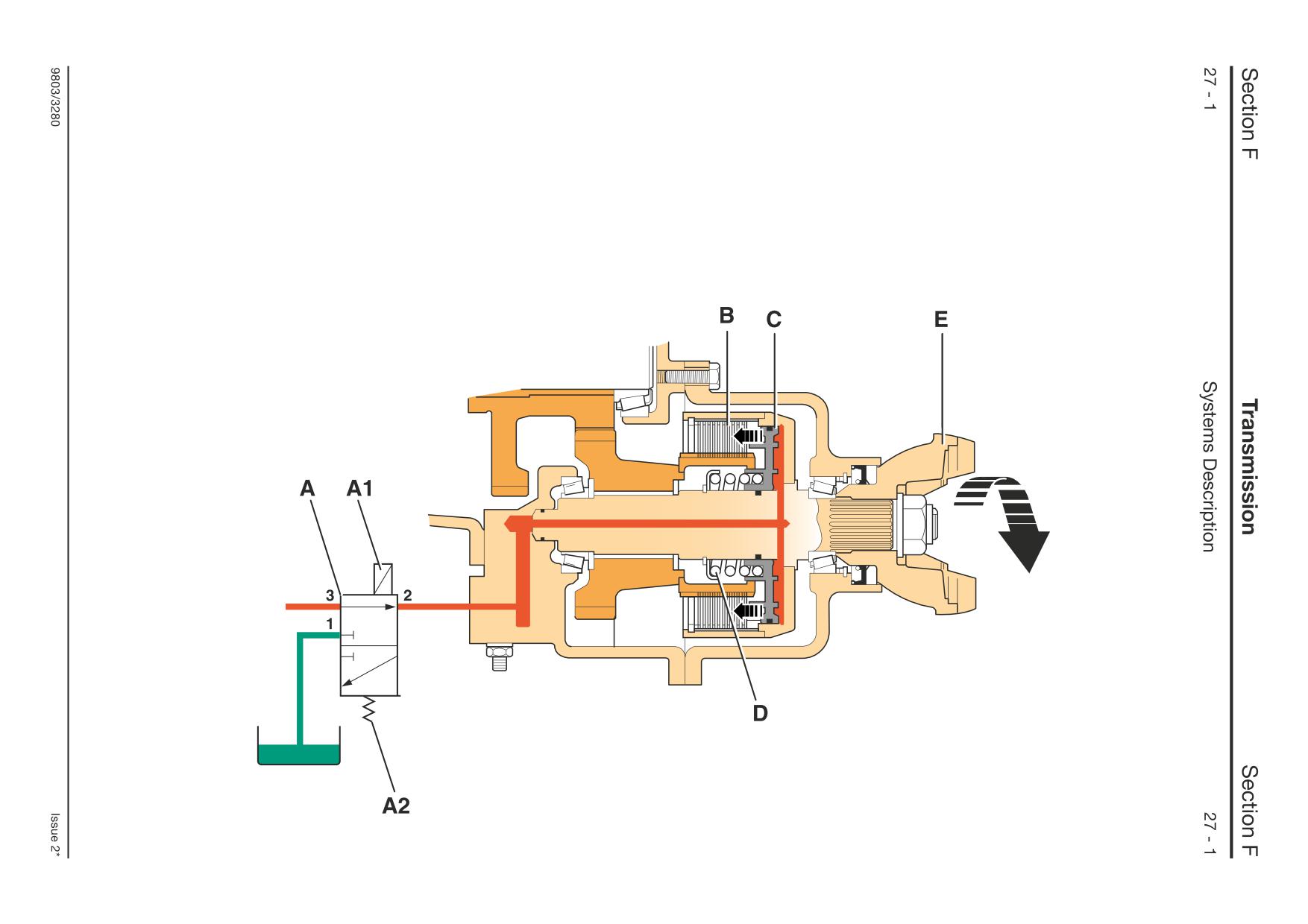
4 Wheel Drive Operation
This clutch is of the 'Pressure-ON (4WD)/Spring-
Pressurised oil is directed to piston C via ports 3
OFF (2WD)' type. The clutch is engaged and
and 2. The piston moves, against spring D, to press
disengaged by introducing or dumping pressurised
the friction/counter plates of clutch pack B
oil behind piston C via a solenoid valve A. The
together, thus driving the output yoke E.
solenoid valve is operated by a switch in the cab.
When the switch is in the 4 wheel drive position,
solenoid valve A is energised. The energised
solenoid A1 causes the valve spool to move and
form a connection between ports 3 and 2.
A406200
Synchro Shuttle Gearbox
2/4 Wheel Drive Clutch Operation
- Pressure ON/Spring OFF Type (cont’d)
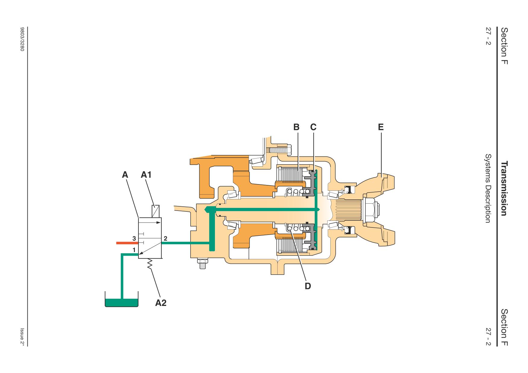
2 Wheel Drive Operation
When the switch is in the 2 wheel drive position,
Because there is no pressure behind piston C, the
solenoid valve A is de-energised. With the solenoid
friction/counter plates of clutch pack B now freely
A1 de-energised, the valve spool moves under the
rotate on the output shaft, thus disengaging drive
force of the spring A2. The oil supply to the piston
to the front axle.
C is blocked (shown at port 3). At the same time oil
vents from the back of piston C to the sump via
ports 1 and 2.
A406210
Synchro Shuttle Gearbox
2/4 Wheel Drive Clutch Operation
- Spring ON/Pressure OFF Type
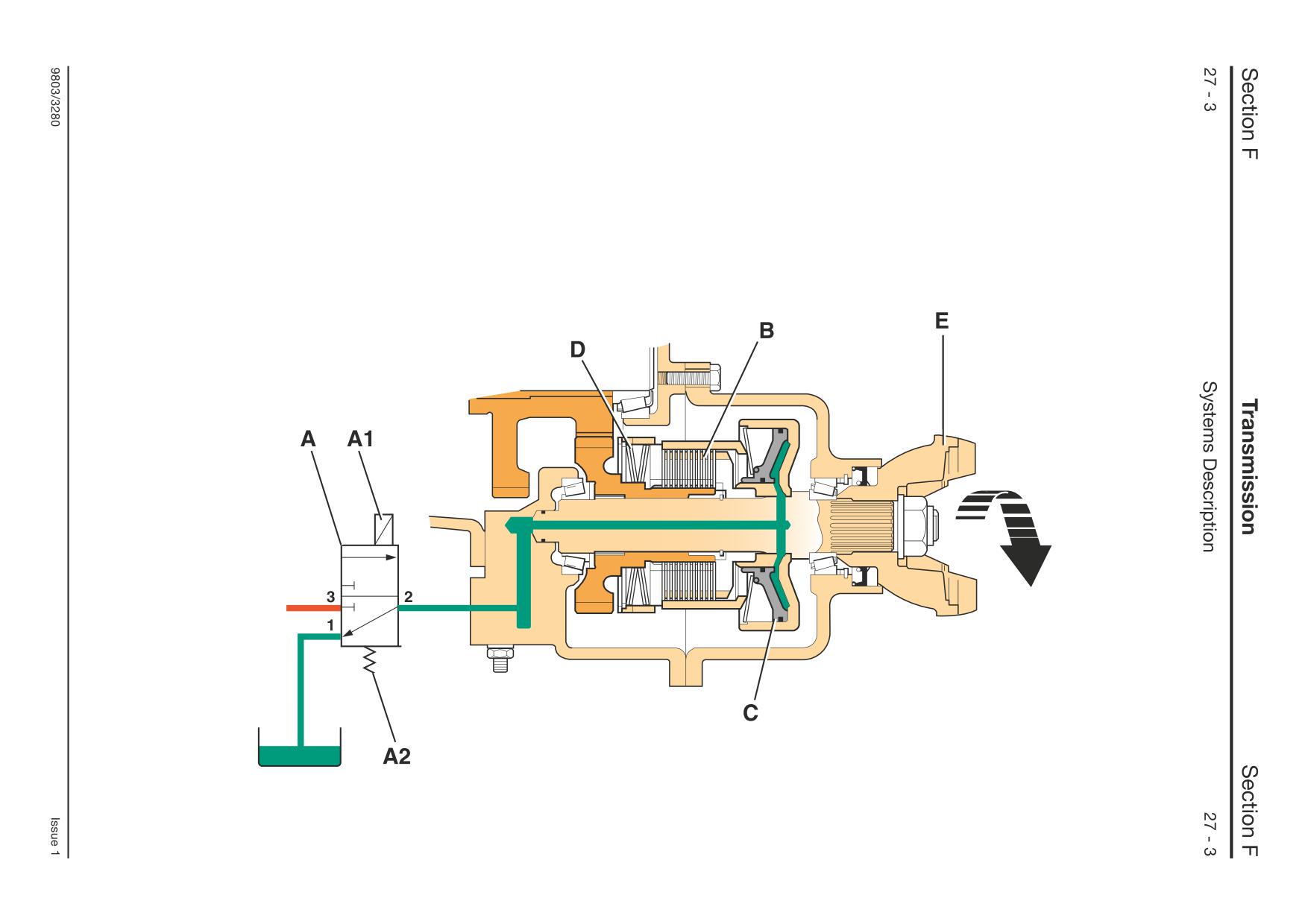
4 Wheel Drive Operation
This clutch is of the ‘Spring-ON (4WD)/Pressure-
Because there is no pressure behind piston C, the
OFF (2WD)’ type. The clutch is engaged and
clutch friction/counter plates of clutch pack B are
disengaged by introducing or dumping pressurised
forced together by disc springs D, thus driving the
oil behind piston C via a solenoid valve A. The
output yoke E.
solenoid valve is operated by a switch in the cab.
When the switch is in the 4 wheel drive position,
solenoid valve A is de-energised. With the solenoid
A1 de-energised, the valve spool moves under the
force of the spring A2. The oil supply to the piston
C is blocked, (shown at port 3). At the same time oil
vents from the back of piston C to the sump via
ports 1 and 2.
A406220
Synchro Shuttle Gearbox
2/4 Wheel Drive Clutch Operation
- Spring ON/Pressure OFF Type (cont’d)
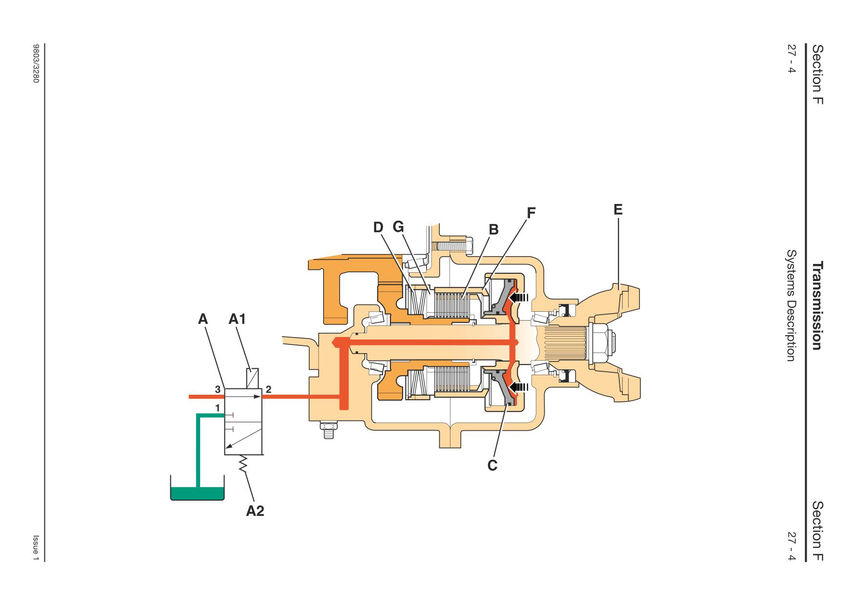
2 Wheel Drive Operation
When the switch is in the 2 wheel drive position,
Because there is no spring force, the
solenoid valve A is energised. The energised
friction/counter plates of clutch pack B now freely
solenoid A1 causes the valve spool to move and
rotate on the output shaft, thus disengaging drive
form a connection between ports 3 and 2.
to the front axle.
Pressurised oil is directed to piston C via ports 3
and 2. The piston moves actuating sleeve F and
then pressure plate G against the force of springs
D, thus releasing the spring force on the clutch
friction/counter plates of clutch pack B.
A406230
Powershift Gearbox
Clutch Operation - Forward, Reverse
The forward and reverse clutch units are very similar in
† The valve E is shown using symbols. For an explanation of
design and operate in the same way. The following
how the symbols work, see Section E, Introduction to
description refers to one unit and can be applied to either
Hydraulic Schematic Symbols.
the forward or reverse clutch units.
The clutch 1 transfers drive from the input shaft A3 to either
Clutch Operation - Mainshaft, Layshaft, 6 Speed
gear G1 or gear G2 depending on which of the two clutches
(A1 or A2) is engaged, transferring drive to the mainshaft.
The mainshaft, layshaft and 6 speed units all incorporate
When neither clutch is engaged, neutral is selected.
one clutch and not two, as in the forward and reverse units.
The operation of the single clutches is the same as for one
The clutches are of the wet, multi-plate type.
clutch in the forward or reverse units.
The clutch housings and input shaft are a one piece
assembly A3. The assembly is permanently driven by the
Clutch Operation - 2/4 Wheel Drive Clutch
engine via the torque converter. Clutch counter plates 3 are
also permanenty driven via meshing teeth inside the clutch
The 2/4 wheel drive clutch is similar to the Synchro Shuttle
housings.
2/4 wheel drive clutch. See Synchro Shuttle Gearbox, 2/4
Clutch friction plates 4 are meshed with the gear/plate
Wheel Drive Clutch Operation.
carriers (G1 and G2).
In the diagram, clutch A1 is engaged. The counter plates 3
and friction plates 4 are pressed together by hydraulically
actuated piston 5. Drive is then transmitted from the input
shaft to the gear G1.
Clutch A2 is disengaged and no drive is transmitted to
gear/plate carrier G2. The gear is also free to rotate on the
input shaft assembly.
Actuation of the hydraulic pistons 10 and 5 is controlled via
two position solenoid valves E1 and E2† .
When neutral is selected, solenoids E1 and E2 are
deactivated and the flow of pressurised oil to the clutches is
blocked. Springs 8 and 9 move the pistons away from the
clutch plates and oil from both pistons is vented to the
sump.
When for example clutch A1 is selected to be engaged,
solenoid valve E1 is energised and solenoid valve E2 is de-
energised. Pressurised oil is diverted via cross drillings
inside the input shaft A3 to the clutch piston 5. Pressure
from clutch A2 is vented to the sump via the solenoid valve
spool E2. Oil is prevented from leaking by seals 6 on the
pistons and ring seals 7 on the input shaft A3.
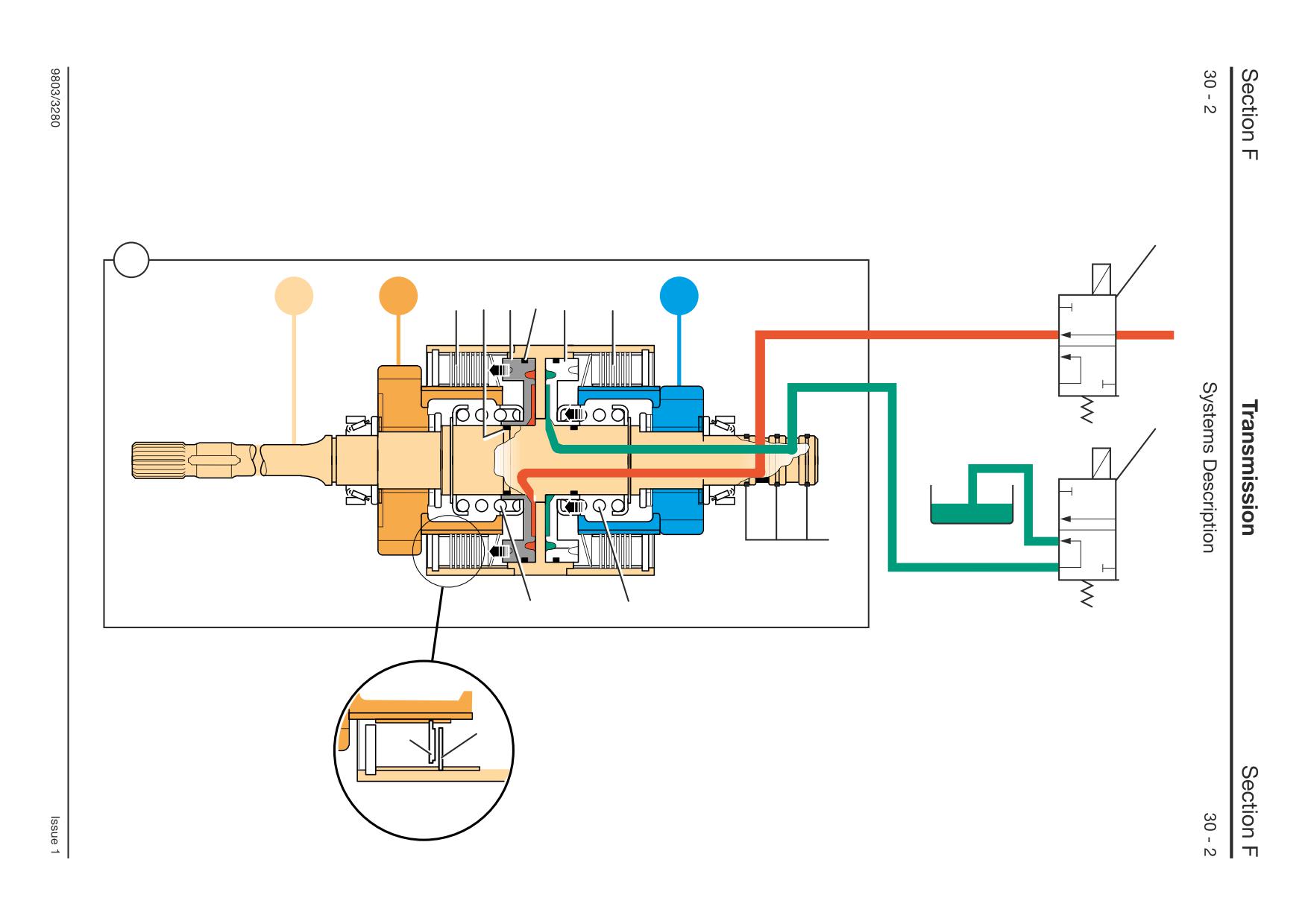
Powershift Gearbox
Clutch Operation - Forward, Reverse
E1
1
A3
G1
A1 6
5
6
10
A2
G2
E2
7
8
9
3
4
A396830
Section F
Transmission
Section F
32 - 1
Electrical Connections
32 - 1
Powershift Gearbox - 4 Speed
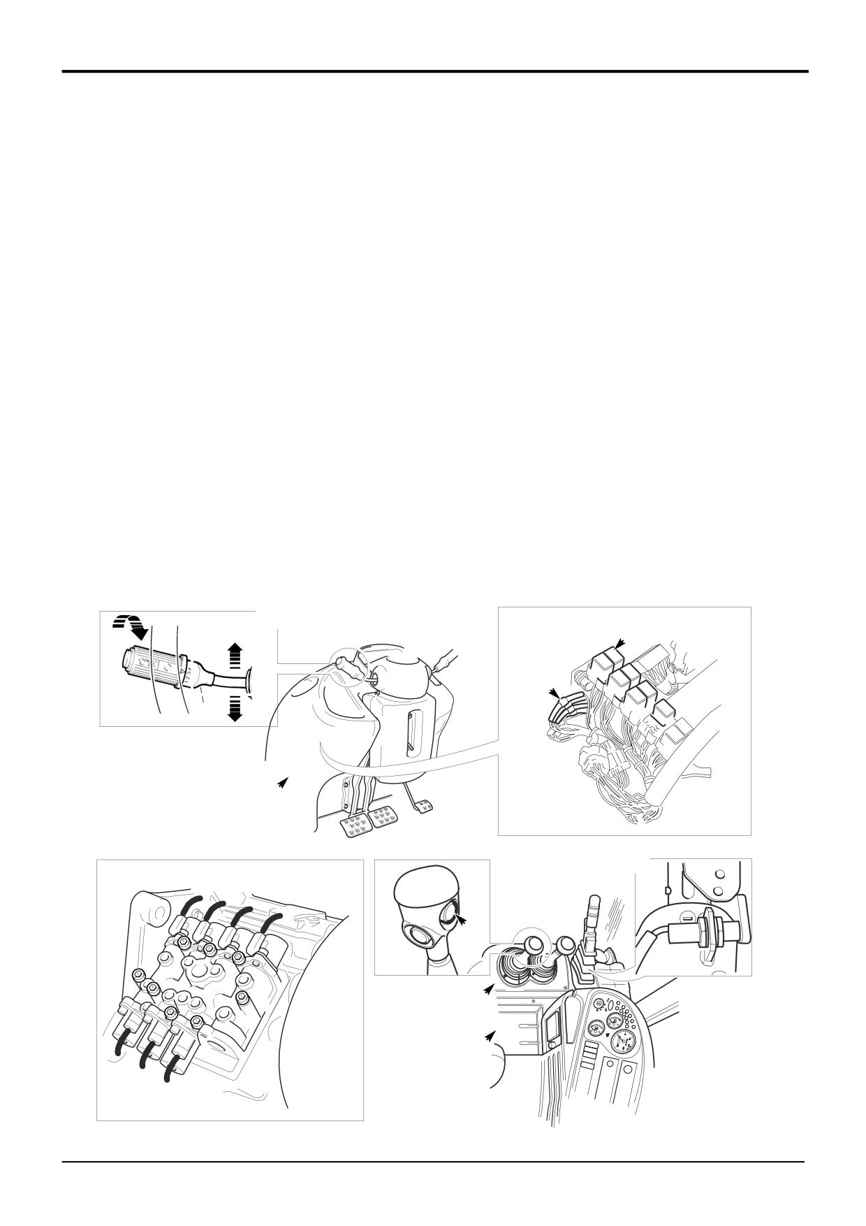
Introduction
This section explains how the electrical system works when
the following gearbox functions are operated:
1st, 2nd, 3rd and 4th gears forward
Neutral
1st, 2nd, 3rd and 4th gears reverse
Transmission dump
Park brake switch
The
4-speed powershift gearbox is controlled using
conventional relays. The relays at A are operated via the
column mounted gear and forward/reverse lever B. The
transmission dump switch C or park brake switch D also
operate a relay at A. The contacts inside the relays energise
the gearbox mounted solenoid control valves E.
Diode ‘gates’ F are also used as logic switches.
To access the relays and connectors it is necessary to
remove the front/steering console panel X and side panels
Y, refer to Section B for the correct procedure.
B
1
A
2
F
3
N
4
F
R
X
D
C
Y
Y
E
A404800
9803/3280
Issue 1
Section F
Transmission
Section F
32 - 2
Electrical Connections
32 - 2
Powershift Gearbox - 4 Speed (cont’d)
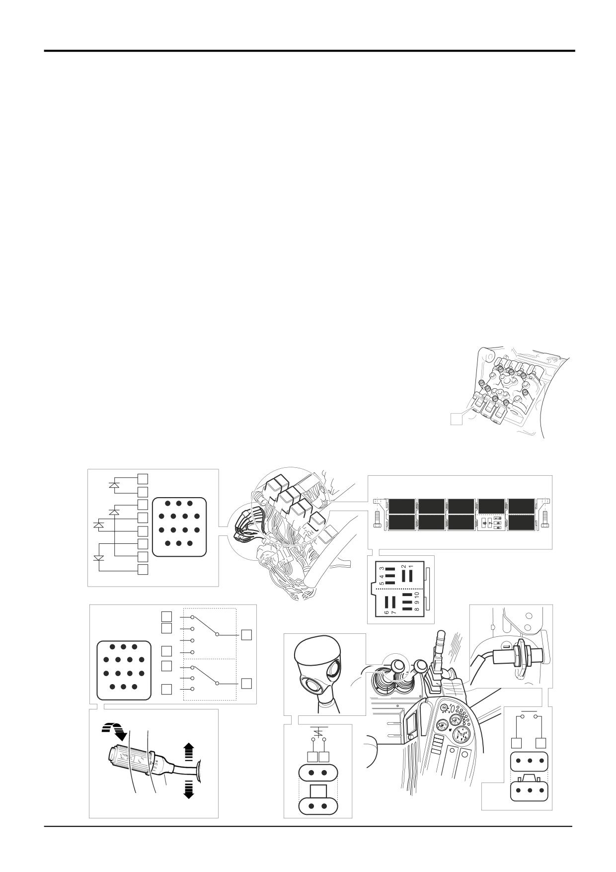
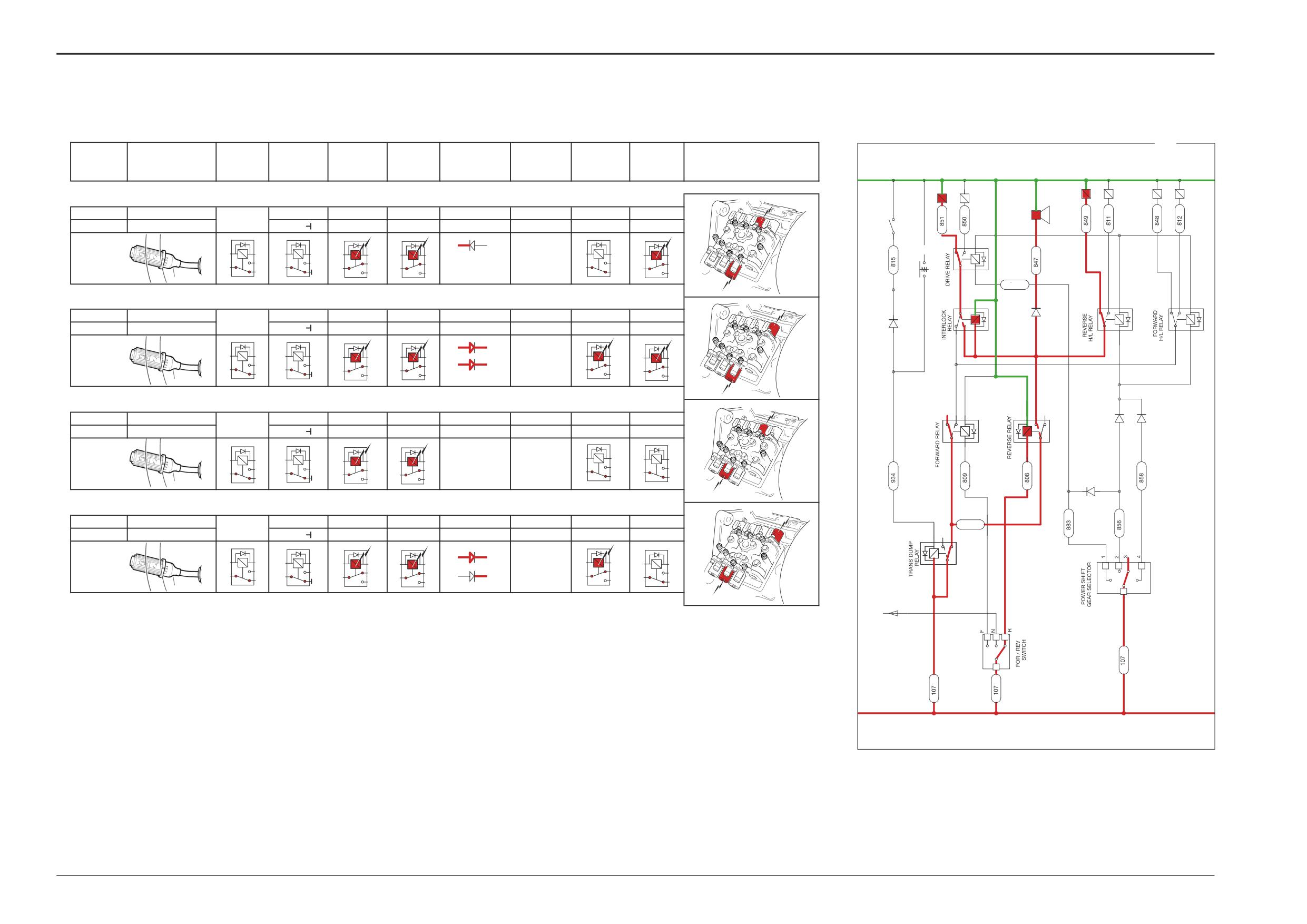
Electrical Connections - Quick Reference
Key
The tables show switch positions together with energised
C50
Reverse alarm
relay and gearbox solenoids for each gearbox function
DW
Park brake switch
(reverse gears are shown on the next page). The numbers
FL
Column switch connector
show which contacts are ‘live’ and also relate to the actual
FK
Diode gate connector
connector pin numbers.
FG
Transmission dump relay
FD2
Forward relay
When fault finding it should be remembered that the system
FE2
Reverse relay
relies on the dump switch and park brake switches
FF1
Interlock relay
functioning correctly, failure of these switches will prevent
FD1
Forward Hi/Lo relay
forward or reverse gears being selected. From the tables it is
FE1
Reverse Hi/Lo relay
possible to see common relay functions which can help
FF2
Mainshaft/Layshaft relay
trace faults. For example we can see that relay FF2 is
NG
Dump switch
energised to engage 1st or 2nd gear. Failure of these gears
to select may indicate a fault with relay FF2.
Gearbox Solenoids
T
Forward low
Note that a non functioning relay or solenoid may not
U
Forward high
indicate a faulty component, the associated wires and
Y
Mainshaft
connectors may have failed. For wire and connector details
Z
Layshaft
see the relevant schematic.
Note: Solenoid S is the
Diagram X
2/4WD solenoid. The 2/4WD
select electrical system is
The diagram X (opposite) shows the electrical circuit for the
not described in this
gearbox control. It is shown with 3rd gear forward selected.
section.
‘Live feed’ wires are coloured red and feed to earth are
green.
S
A405330
7
FK
11
5
3
2
1
FD2
FE2
FF2
FG
6
7
6
5
4
FD1
FE1
FF1
3
11
10
9
8
1
14
13 12
2
4
FL
12
1
9
2
14
3
1
2
3
13
4
4
5
6
7
4
F
8
9
10
11
N
7
10
R
12
13 14
NG
1
3
2
2
A
B
F
3
3
2
1
N
A
B
4
R
DW
3
2
1
A
B
A404820
9803/3280
Issue 1
Section F
Transmission
Section F
32 - 3
Electrical Connections
32 - 3
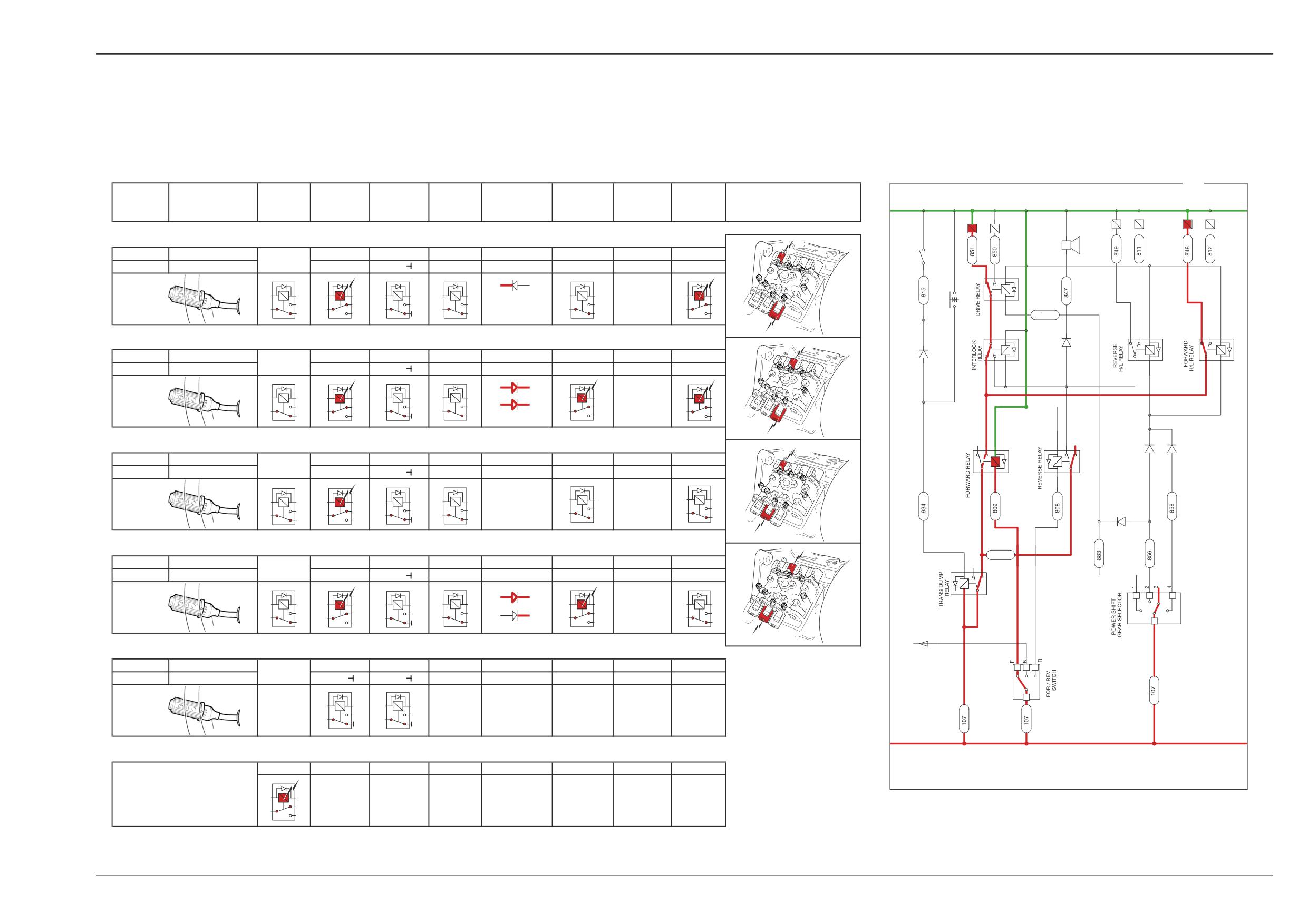
Powershift Gearbox - 4 Speed
Gearbox
Column Switch FL
Relay FG
Relay FD2
Relay FE2
Relay FF1
Diode Gate FK
Relay FD1
Relay FE1
Relay FF2
Gearbox Solenoid
X
function
Dump
Forward
Reverse
Interlock
Forward
Reverse
Mainshaft
Hi Lo
Hi Lo
Layshaft
W
V
T
U
Y
Z
T
C50
1st GEAR
14 - 12
4
6 - 9
3 - 5, 1 - 2
1 - 4
DW
FORWARD
7 - 4
3 - 5, 1 - 2
1 - 4
9 - 6
FF2
4
2
5
4
1
NG
1F
5
3
5
3
2
2
1
3
1
1
1
6
6
1
4
4
9
9
T,Z
883
Z
FF1
6
10
FE1
9
7
10
FD1
9
7
10
11
U
2nd GEAR
14 - 9
2 - 5, 1 - 4
8 -10, 6 - 7
3 - 5, 1 - 2
1 - 4
7
9
7
8
6
8
6
8
FORWARD
7 - 4
3 - 5, 1 - 2
1 - 4
9 - 6
2
5
5
3
10
8
5
3
2F
1
4
2
7
2
1
1
1
6
6
1
4
4
9
U,Z
Z
FD2
FE2
5
6
2
5
5
2
4
T
3rd GEAR
6 - 9
1 - 4
2
3
1 - 4
FORWARD
7 - 4
3 - 5, 1 - 2
1 - 4
9 - 6
1
3
3
1
5
3
3F
1
1
2
1
6
6
1
4
1
4
4
9
9
4
T,Y
Y
U
852
4th GEAR
14 - 13
3 - 6
8 -10, 6 - 7
1 - 4
1 - 4
5
4
FORWARD
7 - 4
3 - 5, 1 - 2
1 - 4
9 - 6
12
9
13
3
6
3
1
5
3
10
8
4F
FG
2
2
5
7
1
1
1
6
6
1
4
4
9
4
14
U,Y
FL
Y
TO NEUTRAL
START RELAY
4 6 10
NEUTRAL
1 - 4
1 - 4
FL
7
N
1
1
4
4
A404640
TRANSMISSION DUMP
5 - 3, 1 - 2
/PARK BRAKE ON
5
3
2
1
A404630
9803/3280
Issue 1
Section F
Transmission
Section F
32 - 4
Electrical Connections
32 - 4
Powershift Gearbox -4 Speed
Gearbox
Column Switch FL
Relay FG
Relay FD2
Relay FE2
Relay FF1
Diode Gate FK
Relay FD1
Relay FE1
Relay FF2
Gearbox Solenoid
Y
function
Dump
Forward
Reverse
Interlock
Forward
Reverse
Mainshaft
Hi Lo
Hi Lo
Layshaft
W
V
T
U
Y
Z
W
1st GEAR
14 - 12
4
6 - 9
3 - 5, 1 - 2
C50
1 - 4
REVERSE
7 - 10
1 - 4
3 - 5, 1 - 2
8 - 10, 7 - 6
DW
4
1
FF2
4
2
5
5
5
3
10
8
5
3
1R
2
7
2
1
1
1
6
6
1
4
4
9
1
3
W,Z
883
Z
FF1
6
FE1
7
10
FD1
7
10
V
9
9
10
11
2nd GEAR
14 - 9
2 - 5, 1 - 4
8 - 10, 6 - 7
3 - 5, 1 - 2
1 - 4
REVERSE
7 - 10
1 - 4
3 - 5, 1 - 2
8 - 10, 7 - 6
7
9
7
8
6
8
6
8
2
5
5
3
10
8
10
8
5
3
2R
2
7
1
4
7
1
1
1
6
6
2
4
4
1
V,Z
Z
W
FD2
FE2
5
6
2
5
5
2 4
3rd GEAR
6 - 9
1 - 4
1 - 4
2
3
REVERSE
7 - 10
1 - 4
3 - 5, 1 - 2
8 - 10, 7 - 6
1
3
3
1
5
3
10
8
3R
2
7
6
1
1
1
6
1
4
4
9
4
W,Y
4
1
Y
V
4th GEAR
14 - 13
3 - 6
8 - 10, 6 - 7
1 - 4
852
1 - 4
REVERSE
7 - 10
1 - 4
3 - 5, 1 - 2
8 - 10, 7 - 6
5
4
3
6
5
3
10
8
10
8
12
9
13
4R
3
1
2
7
7
1
1
1
2
5
6
1
4
6
FG
4
4
V,Y
14
Y
FL
A404740
TO NEUTRAL
START RELAY
4
6
10
FL
7
A404790
9808/3280
Issue 1
Section F
Transmission
Section F
32 - 5
Electrical Connections
32 - 5
Powershift Gearbox - 4 Speed (cont’d)
Electrical Connections - Quick Reference (cont’d)
Key
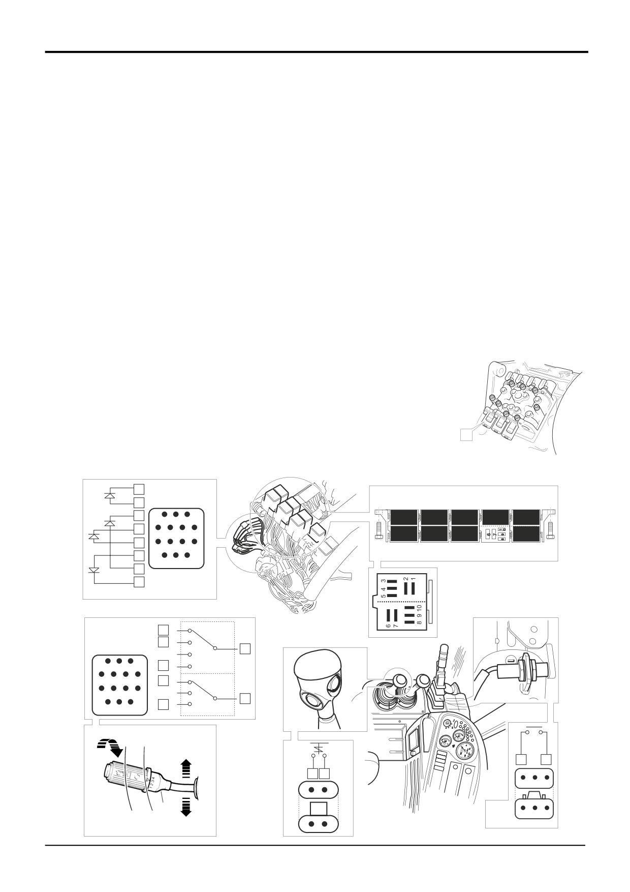
The tables show switch positions together with energised
C50
Reverse alarm
relay and gearbox solenoids for each gearbox function. The
DW
Park brake switch
numbers show which contacts are ‘live’ and also relate to
FL
Column switch connector
the actual connector pin numbers.
FK
Diode gate connector
FG
Transmission dump relay
When fault finding it should be remembered that the system
FD2
Forward relay
relies on the dump switch and park brake switches
FE2
Reverse relay
functioning correctly, failure of these switches will prevent
FF1
Interlock relay
both forward and reverse being selected. From the tables it
FD1
Forward Hi/Lo relay
is possible to see common relay functions which can help
FE1
Reverse Hi/Lo relay
trace faults. For example we can see that relay FF2 is
FF2
Mainshaft/Layshaft relay
energised to engage 1st or 2nd gear. Failure of these gears
NG
Dump switch
to select may indicate a fault with relay FF2.
Gearbox Solenoids
Note that a non functioning relay or solenoid may not
V
Reverse high
indicate a faulty component, the associated wires and
W
Reverse low
connectors may have failed. For wire and connector details
Y
Mainshaft
see the relevant schematic.
Z
Layshaft
Diagram Y
Note: Solenoid S is the
2/4WD solenoid. The 2/4WD
The diagram Y opposite shows the electrical circuit for the
select electrical system is
gearbox control. It is shown with 3rd gear reverse selected.
not described in this
‘Live feed’ wires are coloured red and feed to earth are
section.
green.
S
A405330
7
FK
11
5
3
2
1
FD2
FE2
FF2
FG
6
7
6
5
4
FD1
FE1
FF1
3
11
10
9
8
1
14
13 12
2
4
FL
12
1
9
2
14
3
1
2
3
13
4
4
5
6
7
4
F
8
9
10
11
N
7
10
R
12
13 14
NG
1
3
2
2
A
B
F
3
3
2
1
N
A
B
4
R
DW
3
2
1
A
B
A404820
9803/3280
Issue 1
Section F
Transmission
Section F
32 - 6
Electrical Connections
32 - 6
Powershift Gearbox - 4 Speed
(Machines up to 933756)
Connectors (h3)
CA h3 Î h4
Electrical Connections - Wires and Connectors
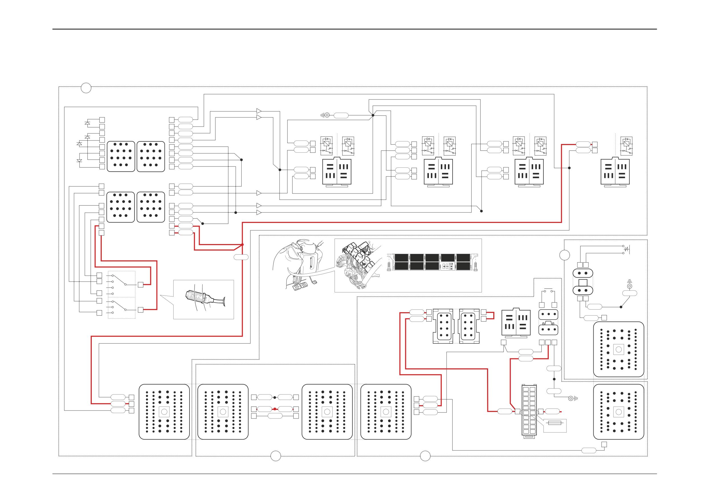
Although the system is straight forward in design it is never
CB h3 Î h2
the less fairly complex in practice. For this reason
CCA Fuses
schematics are divided into 2 parts: Relay Actuation and
CCB Fuses
Gearbox Solenoid Actuation.
CM Park brake relay
DW Park brake switch
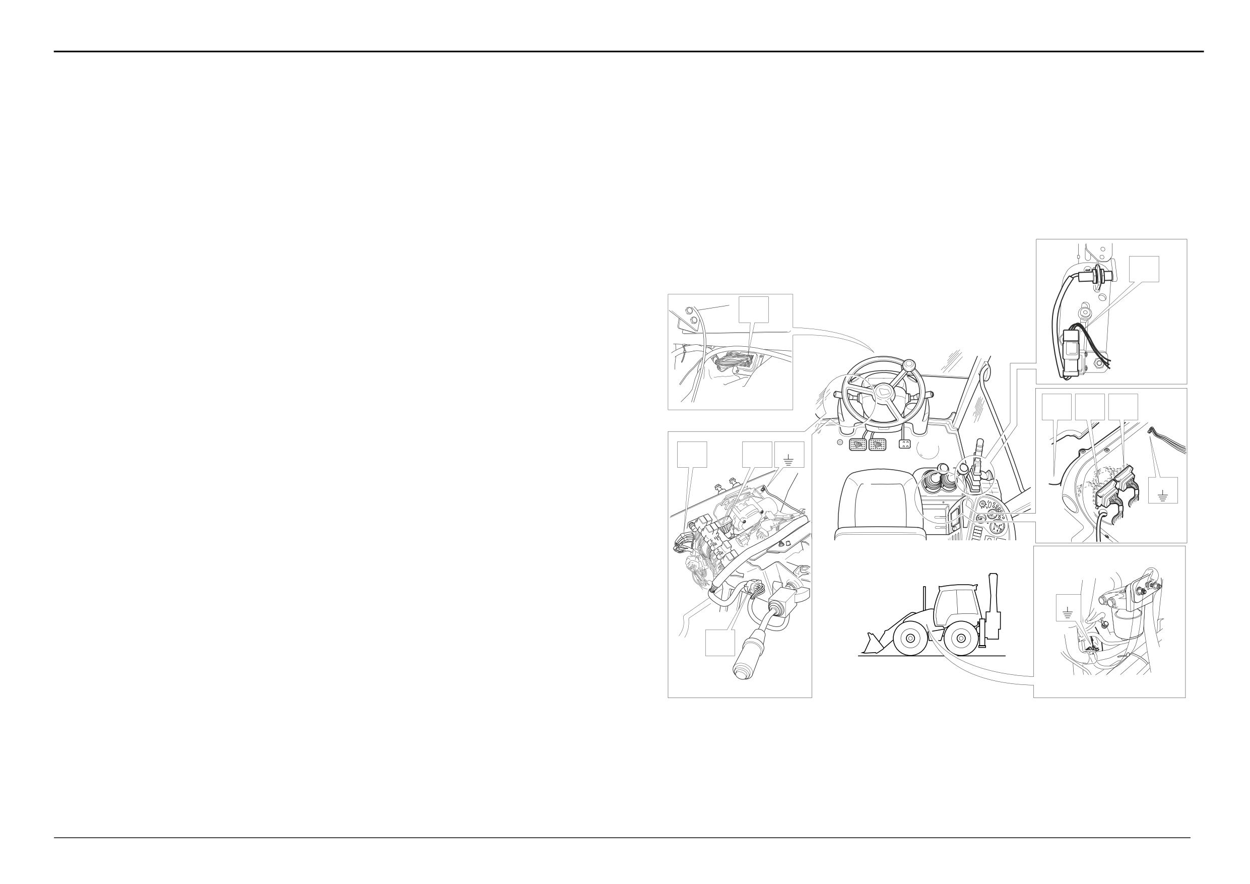
On the electrical diagram opposite the electrical connectors
EA
Immobiliser
(example, FA to LA) are shown looking on the mating face of
EAB Link - immobiliser (if immobiliser is not fitted)
each connector when they are disconnected.
Connectors (h4)
The wire numbers and colours, where appropriate, are
NH h4 Î h3
DW
shown as an aid to identification whilst fault finding.
NG Transmission dump switch
MB1 Earth point
Before fault finding make sure that you understand how the
the electrical circuits work. Most potential faults can be
Splices (h1)
LA
traced using a multimeter to carry out continuity checks on
SL
wires, switches and soleniod coils. Gearbox solenoid coils
SC
can be checked for the correct resistance value as given in
SG
Technical Data. See Service Procedures, Electrical
SH
Testing Methods for more details.
SK
SS
ST
Relay Actuation
NG
LB
NH
Splices h2
For gearbox solenoid actuation see subsequent pages.
CB
CA
SA
SB
Component Key (Relay actuation):
The following key identifies the component connectors on
FK
FA
FB1
Splices h3
the opposite diagrams. Note that the wires coloured red
SC
show the electrical ‘live feed’ to the column gear lever.
DR2
Splices h4
h1
Harness - 721/10940 Front console
SA
h2
Harness - 721/10942 Link
h3
Harness - 721/10936 Side console
Earth Points
h4
Harness - 721/10935 Engine/mainframe
Faults may be caused by poor earth connections. Although
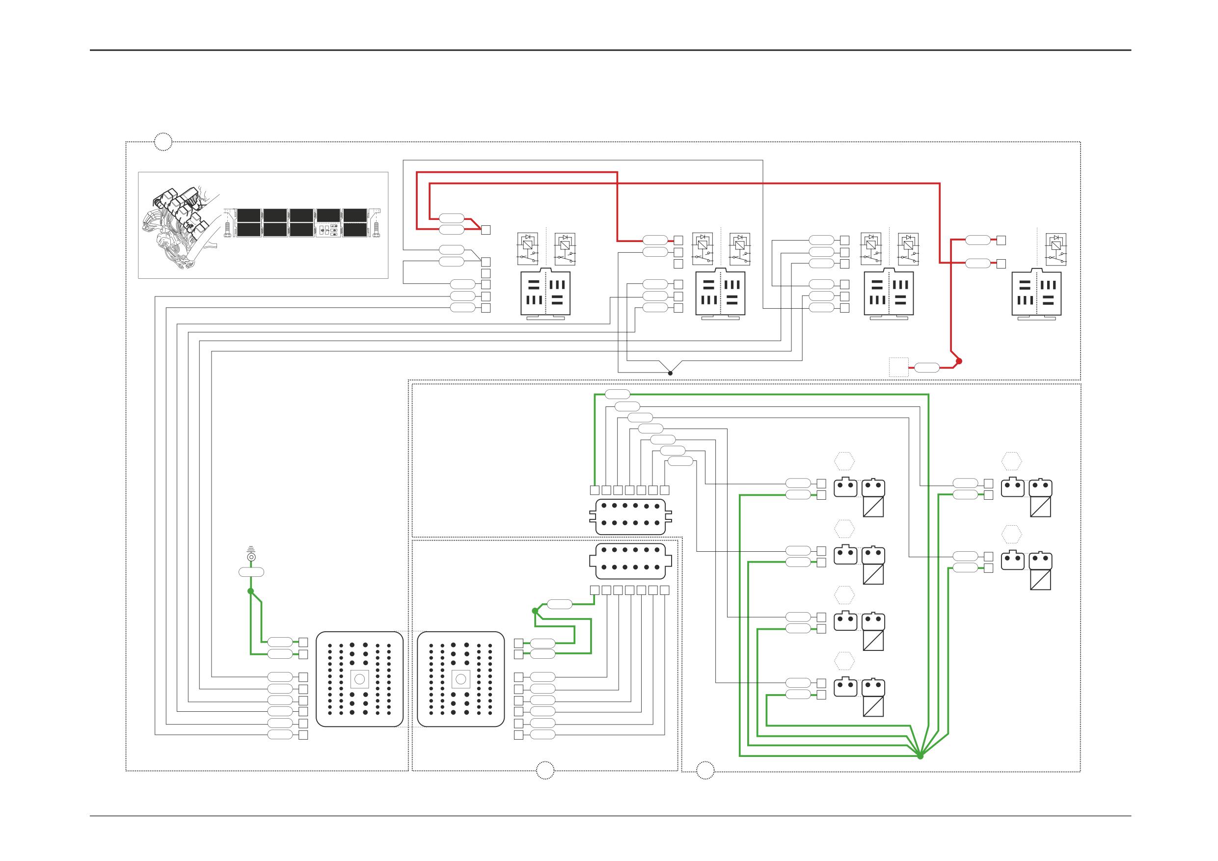
earth connections are shown opposite, it must be
Note: For harness drawings see Section C.
remembered that the cab assembly is earthed via further
earth strap and cable connections. For details of these
Connectors (h1)
connections see Section C, Machine Earth Connections.
FA
h1 Î h2
FB1
Earth point
MB1
FD1
Forward high/low relay
FD2
Forward relay
FE1
Reverse high/low relay
FL
FE2
Reverse relay
FF1
Interlock relay
FF2
Mainshaft/layshaft relay
FG
Transmission dump relay
FK
Diode gate
FL
Column gear lever
A405320
Connectors (h2)
LA
h2 Î h1
LB
h2 Î h3
9808/3280
Issue 2*
Section F
Transmission
Section F
32 - 7
Electrical Connections
32 - 7
Powershift Gearbox - 4 Speed
Relay Actuation
(Machines up to 933756)
h1
FD1, FE1
FB1
621
11
11
815
SA
FD1, FE1
7
7
934C
FD1
FD2
FE1
FE2
FF1
FF2
FG
5
5
884
FK
6
6
884A
600AC
5
10
8
5
3
600AD
5
10
8
5
3
883B
3
10
8
5
3
107AL
3
5
3
3
3
2
1
3
2
1
3
858A
7
2
7
2
7
2
2
809
3
6
1
808
3
6
1
600AG
5
6
1
934D
5
1
1
1
856A
9
4
9
4
9
4
4
7
6
5
4
7
6
5
4
1858A
2
2
11
10
9
8
2
856B
SC
11
10
9
8
5
4
3
5
4
3
5
4
3
5
4
3
6
6
6
6
4
4
883E
14
13 12
14
13 12
7
7
7
7
884D
8
600AF
10
1858C
8
SK
SH
2
2
2
2
600AE
10
1
884C
8
1
600LF
10
1
1
8 9 10
8 9 10
8 9 10
8 9 10
9
9
856
FL
FD2
4
4
809
1
2
3
3
2
1
FE2
10
4
5
6
7
7
6
5
4
10
808
12
8
9
10
11
11
10
9
8
12
883
ST
13
12
13 14
14
13 12
13
858
FF2
SL
SU
14
14
107A
7
7
107R
SS
2c
107
h4
FD2
FE2
FF2
FG
A
B
FD1
FE1
FF1
A
B
12
1
9
2
NG
14
DW
3
MB1
A
B
13
4
600A
A
B
4
F
EA
EAB
CM
3
2
N
600EZ
7
SA
10
R
107H
6
6
5 4
3
6
3
2
1
107
3
4
5
5
4
3
7
934A
42
3
6
6
3
2
12
20
24
28
35
48
1
2
7
7
2
8 9 10
3
2
1
1
8
8
1
9
3
1
2
NH
815
107S
600BF
1
13
21
25
29
37
FA
LA
LB
CB
CCA
SC
12
24
30
36
48
60
60
48
36
30
24
12
12
24
30
36
48
60
60
48
36
30
24
12
20
19
12
20
24
28
35
48
619
SA
18
17
934
7
7
934
934F
7
7
934F
16
15
107
34
14
13
SB
34
107H
DR2
34
107H
107
34
12
11
815
10
107
002
10
815A
10
10
9
9
IGN
CA
10
815A
10
8
7
6
4
4
3
FUSE A5
2
1
1
13
25
31
39
49
49
39
31
25
13
1
1
13
25
31
39
49
49
39
31
25
13
1
1
13
21
25
29
37
42
934F
h2
h3
A404520
9803/3280
Issue 1
Section F
Transmission
Section F
32 - 8
Electrical Connections
32 - 8
Powershift Gearbox - 4 Speed
Gearbox Solenoid Actuation
(Machines up to 933756)
h1
FD2
FE2
FF2
FG
852N
FD1
FD2
FE1
FE2
FF1
FF2
FG
FD1
FE1
FF1
852P
1
852P
1
999
1
107AD
1
10
8
5
3
10
8
5
3
10
8
5
3
5
3
846B
7
2
1858
2
7
2
850
2
7
2
2
6
1
6
1
6
1
1
9
4
9
4
9
4
4
846
2
4
851
4
852N
4
4
5
4
3
5
4
3
5
4
3
5
4
3
6
6
6
6
846
6
1858D
6
999
6
7
7
7
7
812
7
2
811
7
2
1858B
7
2
2
1
1
1
1
812/848
9
8 9 10
811/849
9
8 9 10
846B
9
8 9 10
8 9 10
SS
X
107
ST
600Z
851
850
849
811
848
812
F
G
848
1
851
1
1
11
10
9
3
8
4
1
2
2
1
1
2
2
1
600BX
2
600BZ
2
C30
T
C40
Y
12
11
10
9
5
6
C10
1
2
3
4
8
7
E
H
FB1
812
1
1
2
3
4
5
6
850
1
1
2
2
1
LC
600BS
2
1
2
2
1
600BY
2
621
12
11
10
9
8
7
C20
U
C50
Z
1
11
10
9
3
8
4
SA
I
600Z
SC
849
1
FA
LA
1
2
2
1
600CA
2
12
24
30
36
48
60
60
48
36
30
24
12
600DN
50
50
600DN
C60
W
600DP
49
49
600DP
J
851
19
19
851
811
1
850
16
16
850
1
2
2
1
600BT
2
811/849
15
15
811/849
811
13
13
811
C70
V
1
13
25
31
39
49
49
39
31
25
13
1
812/848
11
11
812/848
812
6
6
812
SA
h2
h5
A404530
9808/3280
Issue 1