JCB 3CX, 4CX, 214e, 214, 215, 217 & VARIANTS Backhoe Loader. Service Manual - page 25
Section F
Transmission
Section F
50 - 1
Service Procedures
50 - 1
Front Axle - SD55, SD70
Renewing the Pinion Oil Seal
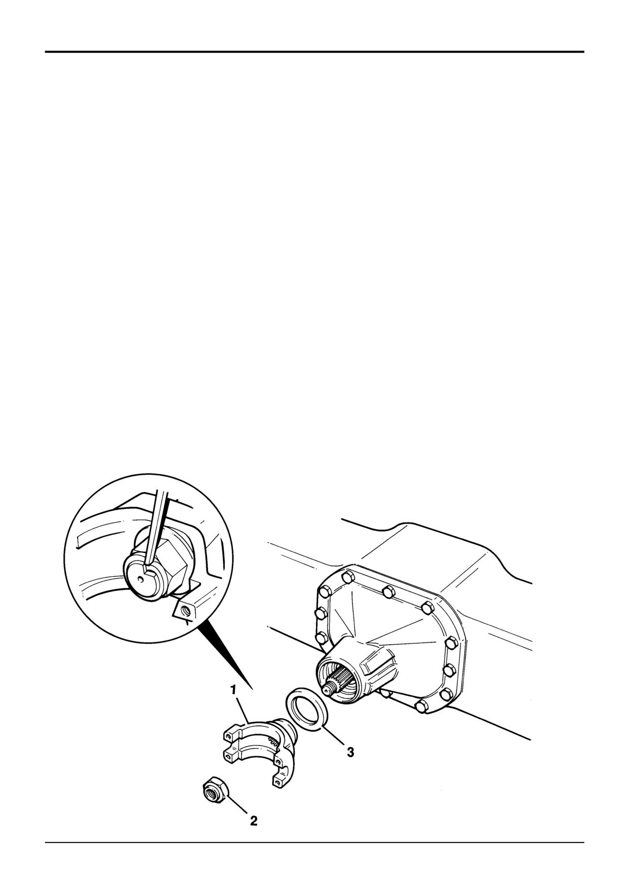
The pinion oil seal 3 may be renewed without removing the
4
Check the sealing surface on the yoke for wear or
axle from the machine.
damage. renew the yoke if necessary.
! WARNING
5
Fit the yoke and temporarily fit the old stake nut 2.
Tighten the nut with a torque wrench, aligning the
A raised and badly supported machine can fall on you.
scriber marks. Note the tightening torque required.
Position the machine on a firm, level surface before
raising one end. Ensure the other end is securely
6
Remove and discard the old nut. Fit a new nut and
chocked. Do not rely solely on the machine hydraulics or
tighten to the torque determined at step 5.
jacks to support the machine when working under it.
6.1 Measure the rolling torque. The reading should be
Disconnect the battery, to prevent the engine being
0.5 to1Nm (0.37 to 0.74lbf ft; 0.05 to 0.1kgf m)
started while you are beneath the machine.
GEN-001
more than that recorded in Step 1 (see Note).
1
Remove the roadwheels and uncouple the axle
6.2 If necessary, progressively torque tighten the nut to
propshaft. Measure the axle rolling torque and record
a maximum of 300 Nm (221 lbf ft) to achieve
the reading. Mark the relative positions of the pinion
correct rolling torque.
shaft 4 and nut 2 with a scriber.
Note: If the rolling torque figure (new pinion seal fitted)
2
Using Service Tool 892/00812, remove the drive yoke 1
exceeds the reading recorded in step 1 by 1Nm (0.74 lbf ft;
together with its stake nut 2.
0.1 kgf m) or more, or a minimum torque of 250 Nm (184 lbf
ft) can not be achieved then the pinion assembly must be re-
3
Remove the seal 3 and fit a new one. Be sure not to
built using a solid spacer, see the apprpriate axle assembly
damage the seal housing. Pack between the lips of the
procedure.
new seal with grease before fitting.
6.3 Stake the nut using a square ended staking tool.
7
Refit the roadwheels and couple the propshaft.
Typical Axle Shown
9803/3280
Issue 1
Section F
Transmission
Section F
51 - 1
Service Procedures
51 - 1
Rear Axle - SD80, PD70
Renewing the Pinion Oil Seal
The rear axle pinion oil seal is renewed using the same
procedure as Front Axle SD55, SD70 but note the following:
The rear axles are fitted with a brake disc/drive flange in
place of the yoke on front axles. For the brake disc removal
procedure see Section G, Brakes, Service Procedures.
9803/3280
Issue 1
Section F
Transmission
Section F
52 - 1
Service Procedures
52 - 1
Rear Axle - SD80, PD70
Brakes - Testing for Piston Seal Leakage
See Section G, Brakes, Service Procedures.
9803/3280
Issue 1
Section F
Transmission
Section F
55 - 1
Service Procedures
55 - 1
G
K
J
H
E
D
F
A396910
S266880
L
C
A
B
9803/3280
Issue 1
Section F
Transmission
Section F
55 - 2
Service Procedures
55 - 2
Synchro Shuttle Gearbox
Torque Converter Stall Test
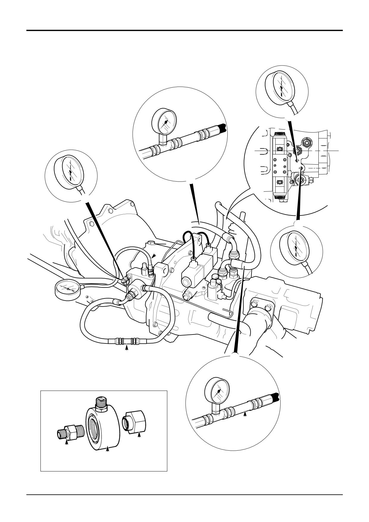
Ensure that the engine and transmission are at normal
2
Start engine and run at 1000 rev/min. The flowmeter will
working temperature. Run engine at maximum speed and
show the Pump Flow which should be as shown in
check the No Load Speed (High Idle Speed - U.S.A). See
Technical Data. A low reading indicates a worn pump
Engine Technical Data for correct figure; adjust if necessary.
or blocked suction strainer. The pressure gauge will
show the Main Line Pressure (see Technical Data). A
Apply parking brake and footbrake firmly, select 4th Speed
low reading can be caused by either a faulty pressure
Forward and open throttle fully. Engine speed should be as
maintenance valve or a worn pump. A high reading
specified at Torque Converter Stall in Transmission
indicates a faulty pressure maintenance valve or, if the
Technical Data. Select Reverse and repeat test.
pump flow is low, the oil cooler may be blocked.
Note: When fully engaged, the parking brake electrically
3
Stop engine, remove flow test adapters and refit filter.
disconnects the transmission drive; this prevents the
Connect pressure gauge and flowmeter into converter
machine from being driven with the parkbrake on. Therefore,
out line as shown at F. Run engine at 1000 rev/min with
so that we can complete the test, move the parkbrake lever
transmission in Neutral and note Converter Out
fractionally forward until the warning light is just
Pressure and Oil Cooler Flow, which should be as
extinguished; hold the lever in this position for the duration
shown in Technical Data. A high pressure together with
of the test. DO NOT move the lever too far forward,
low flow could be caused by a blocked oil cooler. (See
otherwise the parkbrake will not be fully operational.
also check 7.)
Alternatively, disconnect the switch at the park brake.
4
With parking brake and footbrake firmly applied, select
DO NOT stall the converter for longer than 10 seconds or
Forward and check flow reading, which should not fall
the transmission fluid will overheat.
by more than 4.5 litres (1 UK gal; 1.2 US gal) per
minute. A low reading indicates a high leakage rate in
If engine speeds are higher than the stated figures check the
that particular clutch, which could be caused by worn
transmission for clutch slippage or internal leakage.
or broken piston seals or shaft sealing rings. Select
Reverse and repeat the test.
If engine speeds are below the stated figures either the
engine is losing power and should be serviced/overhauled or
5
If the clutch leakage rate is high, the Clutch Pressures
the torque converter reaction member clutch is slipping. To
may be checked by connecting the pressure gauge into
check the engine, select Neutral, open throttle fully and
ports G and H and repeating test 4. A low reading (see
operate an excavator service to 'blow off' the main relief
Technical Data) would confirm a high leakage rate in
valve. Engine speed should fall to slightly above the
the particular clutch selected.
Maximum Governed Speed (see Engine Technical Data). If
engine speed is correct the torque converter is faulty.
6
Stop engine, connect the pressure gauge into port J in
the transmission, and fit a load valve L into the
Note: Maximum Governed Speed is a datum figure only. It
converter out line (see note).
cannot be adjusted or checked with the engine installed in
the machine.
Note: Make sure that the load valve L has been screwed
fully out before starting the engine, otherwise the converter
Pressure and Flow Test
seals will be damaged.
Note: The tests must be carried out only in the following
Start engine, run at 1000 rev/min and slowly screw
down the load valve whilst observing the gauge
order, step by step.
reading, which should rise to the setting of the
Converter Relief (Safety) Valve (see Technical Data).
! WARNING
DO NOT allow the pressure to exceed 10.3 bar (150
Take care when disconnecting hydraulic hoses and
lbf/in2) or damage to the converter seals will be caused.
fittings as the oil will be HOT.
Trans 1-2
If the reading is higher than specified, the relief (safety)
valve must be faulty. A low reading indicates a faulty
relief (safety) valve, leaking converter 'piston ring' type
1
Stop engine, remove transmission filter and filter head
seal or leaking pump seal.
adapter. Fit adapter A (892/00920) into the gearbox
casing. Fit test adapter B (892/00301) and secure with
7
Stop engine and connect pressure gauge and
adapter C
(892/00302). Connect flowmeter D
flowmeter into return line from oil cooler to transmission
(892/00229) as shown and connect a 0-20 bar (0-300
as shown at K. Start engine, and with transmission in
lbf/in2) pressure gauge to test connector E (see Service
Neutral check flowmeter reading, which will show the
Tools, Section 1).
Cooler Flow Rate (see Technical Data). The pressure
gauge will show the Lubrication Pressure (see
Technical Data). Low flow and pressure readings could
indicate a blocked oil cooler.
9803/3280
Issue 1
Section F
Transmission
Section F
57 - 1
Service Procedures
57 - 1
Synchro Shuttle Gearbox
Forward/Reverse Solenoid Control Valve
Dismantling
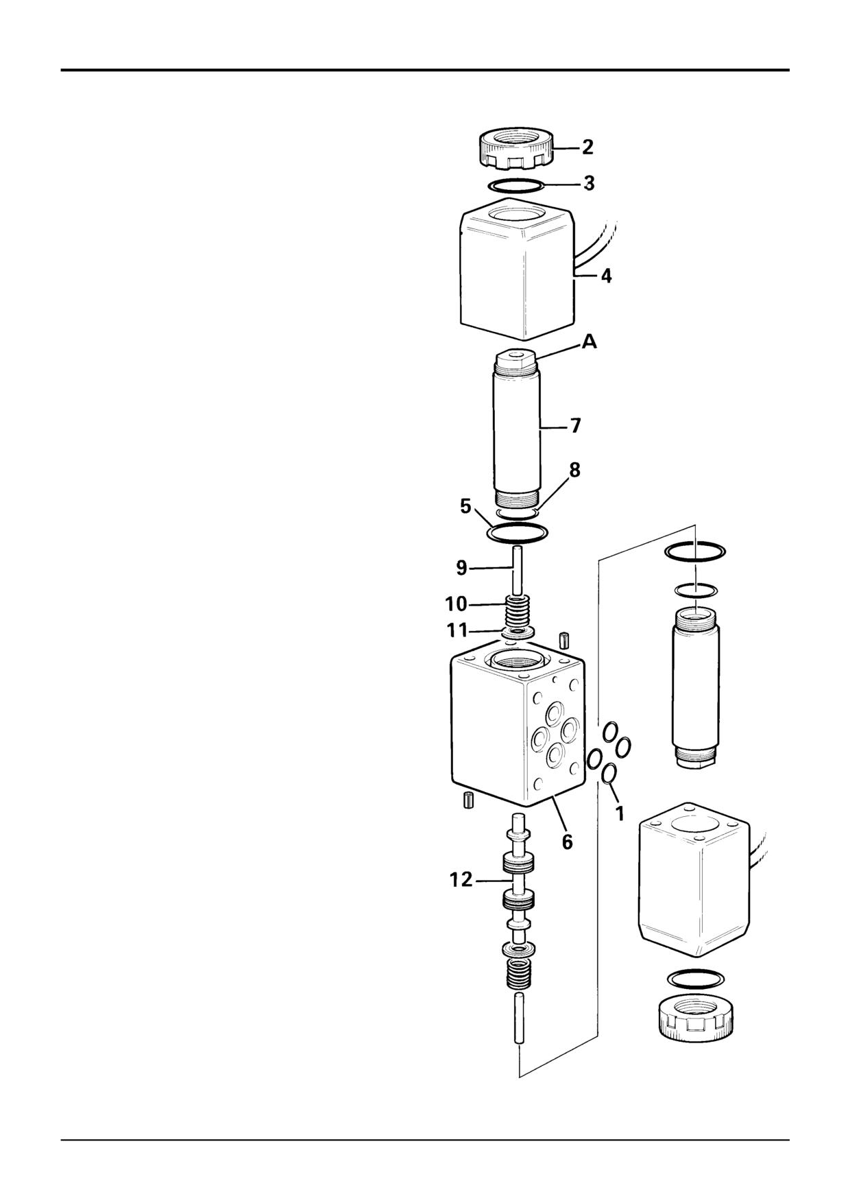
Unscrew the knurled nut 2 and remove 'O' ring 3, withdraw
the solenoid 4 and 'O' ring 5.
Hold the solenoid valve body 6 in a vice, using the spanner
flats A, remove spindle 7 and 'O' ring 8.
Pull out actuating pin 9, spring 10, spring retainer 11, and
spool 12.
Inspect the spool and spool bore for signs of wear, nicks
scratches etc.
Assembling
Assembly is reversal of the dismantle procedure.
Renew all 'O' rings.
Lightly lubricate all parts with clean transmission fluid before
assembling.
Check that the flying leads are secure and that the
connectors are intact.
Torque Settings
Item
Nm
kgf m
lbf ft
2
10 to 15
1 to 1.5
8 to 10
9803/3280
Issue 1
Section F
Transmission
Section F
63 - 1
Service Procedures
63 - 1
2
6
B
B
1
A
D
C
D
2
C
3
X
5
4
A405990
9803/3280
Issue 1
Section F
Transmission
Section F
63 - 2
Service Procedures
63 - 2
Powershift Gearbox
Gearbox Hydraulic Pump -
Removal and Replacement
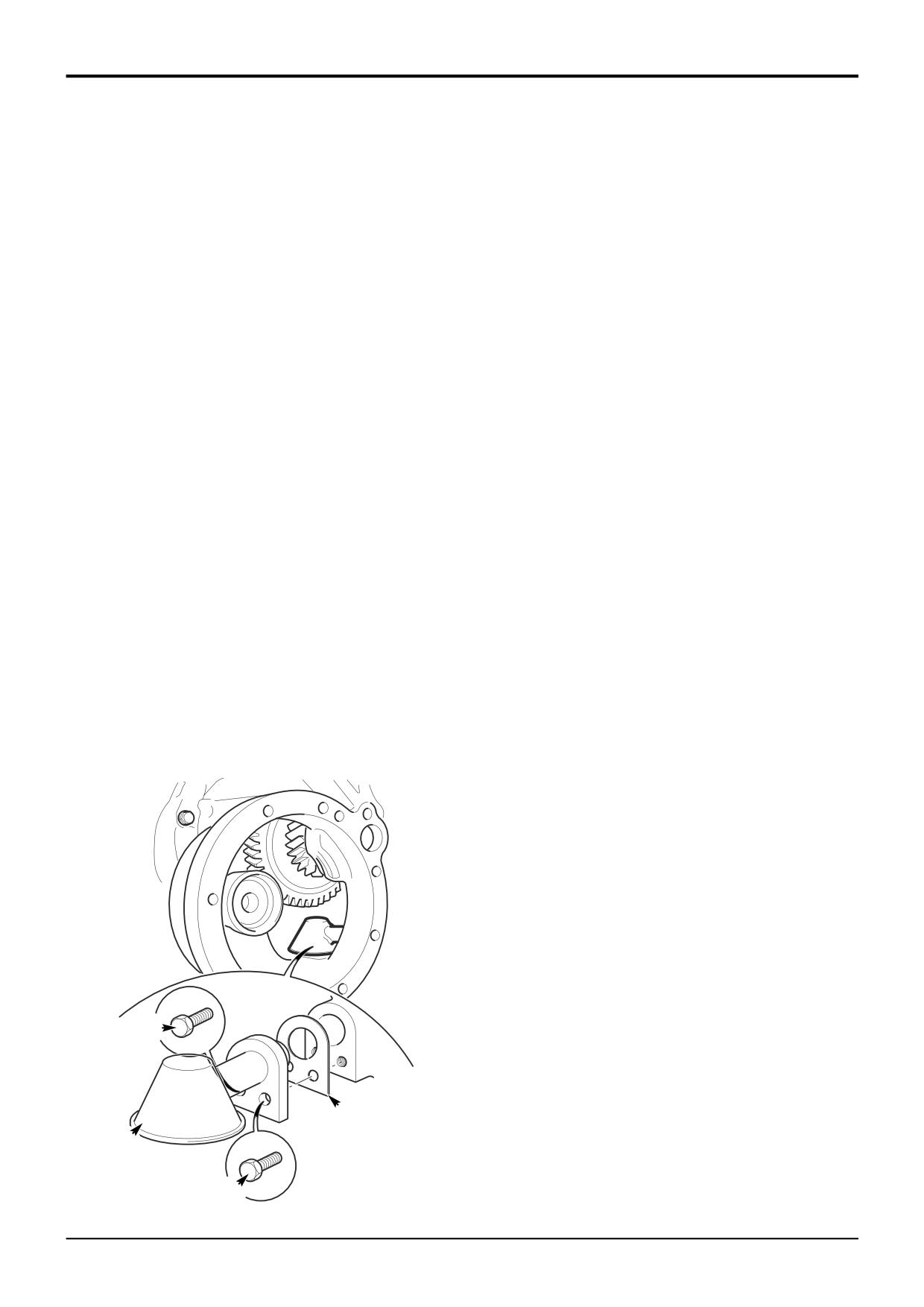
The gearbox hydraulic pump is located at the input end of
Replacement
the gearbox. The gearbox must be removed from the
machine to enable removal and replacement of the pump.
1
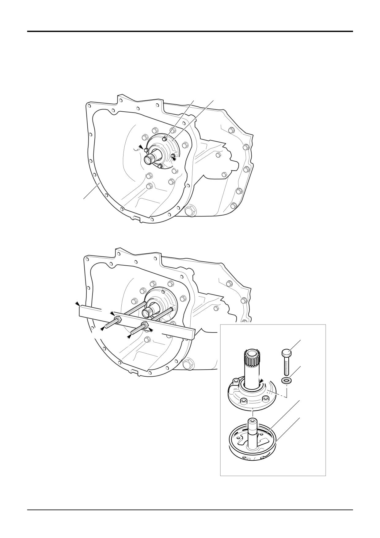
Fit a new ‘O’ ring 5 to the locating bore inside the
housing 1. Lightly oil the ‘O’ ring.
Removal
2
Make sure that the pump is fitted with a new oil seal,
1
Remove the gearbox from the machine, see Powershift
see Powershift Gearbox, Inspection, step 4.
Gearbox Removal and Replacement.
Fit a new sealing ring 4. Locate the pump over the input
shaft aligning the bolt holes. Apply JCB Threadlocker
IMPORTANT NOTE: After removing the gearbox DO NOT
and Sealer to bolts 2. Fit the bolts together with new
REMOVE THE TORQUE CONVERTER HOUSING 1 from the
sealing washers 3. Progressively torque tighten the
gearbox. A simple service tool (A) must be manufactured to
bolts to 28 Nm (20 lbf ft).
enable the pump assembly to be removed. See
Transmission, Service Tools for details.
3
Pour some clean, new, oil into the pump at position X.
2
Undo the 4 fixing bolts 2. Discard the sealing washers
3.
3
Using a set of M10 x 1.5 taps carefully tap the 2 holes
B in the pump assembly 6. Start with the taper tap (be
sure not the damage the tapped holes in the gearbox
front case beneath) and finish with the plug tap. Ensure
that the thread is at least 35 mm (1.38 in) deep and
both the pump body and stator are threaded. Be sure
to remove ALL swarf before proceding.
4
Screw in a 250 mm (10 in) length of M10 threaded rod
C into each hole B. Position the reaction bar A as
shown. Progressively screw down the M10 nuts D to
withdraw the pump assembly from its housing.
5
Remove and discard the pump sealing ring 4. Remove
and discard the ‘O’ ring 5 from the pump locating bore
in the housing 1.
Note: The pump should be dismantled and inspected, see
Powershift Gearbox - Inspection. Note that a pump which
is badly worn or damaged may have caused further damage
to the gearbox, see Powershift Gearbox - Dismantling.
9803/3280
Issue 1
Section F
Transmission
Section F
64 - 1
Service Procedures
64 - 1
Powershift Gearbox
Suction Strainer - Removal and Replacement
Removal
Replacement
The suction strainer is located inside the gearbox front case.
Replacement is the reverse of the removal sequence but
Access is gained by removing the 4WD clutch assembly.
note the following:
1
Park the machine on level ground, apply the parking
1
Fit a new gasket C.
brake and chock the wheels.
2
Make sure that no loose components or debris have
2
Allow transmission oil to cool and then drain the oil, see
been left inside the gearbox casing.
Powershift Gearbox, Changing the Oil, Routine
Maintenance.
3
Before replacing the 4WD assembly make sure that all
traces of gasket or gasket compound have been
3
Disconnect the propshaft from the 4WD unit, see
removed from the mating faces, see Powershift,
Propshaft, Removal and Replacement.
Gearbox, Inspection.
4
Remove the 4WD unit, see Powershift Gearbox,
Dismantling Step 6 - Remove the 4WD Clutch
Assembly.
5
Using a 13 mm ring spanner, reach inside the casing
and undo the 2 suction strainer retaining bolts A. Be
sure to retrieve the bolts from inside the gearbox.
6
Push the suction strainer B away from you (towards the
rear of the gearbox) to disengage it from the gearbox
casing. Remove the strainer via the 4WD aperture.
7
Make sure that the gasket C is retrieved. Discard the
gasket.
8
Clean the suction strainer by flushing with a solvent
cleaner. Inspect the strainer mesh for tears or splits.
Renew the suction strainer if the mesh is damaged.
A
C
B
A
A403940
9803/3280
Issue 1
Section F
Transmission
Section F
65 - 1
Service Procedures
65 - 1
Powershift Gearbox
Torque Converter Stall Test
The purpose of the stall test is to check the performance of
Note: When fully engaged, the parking brake electrically
the transmission by ‘stalling’ the torque converter. This is the
disconnects the transmission drive; this prevents the
point at which, due to torque applied by the engine the
machine from being driven with the parkbrake on. Therefore,
torque converter stops transmitting drive to the gearbox.
so that we can complete the test, move the parkbrake lever
The engine speed at which ‘stalling’ occurs is compared to
fractionally forward until the warning light is just
speeds recorded for a machine in normal condition (given in
extinguished; hold the lever in this position for the duration
Technical Data). Abnormal stall speed results can be used
of the test. DO NOT move the lever too far forward,
to identify a number of possible faults with the transmission,
otherwise the parkbrake will not be fully operational.
typically gearbox hydraulic and clutch faults.
Alternatively, disconnect the switch at the park brake.
Note: DO NOT stall the converter for longer than 10 seconds
3
Select 1st speed forward drive and open throttle fully.
or the transmission fluid will overheat. Make sure that the oil
Record the engine speed from the tachometer. Repeat
level is correct and at normal operating temperature.
the test for 2nd and 3rd speed forward and record the
readings.
Before completing the following test, remove the
transmission dipstick. If there is any sign of smoke emitting
4
Repeat step 3 except this time select 1st, 2nd and 3rd
from the dipstick tube STOP THE TEST IMMEDIATELY and
gear reverse drive respectively. Record the readings.
dismantle the transmission for servicing.
5
All recorded readings should be as specified at Torque
By performing the tests in the first 3 gears in forward and
Converter Stall in Transmission Technical Data.
reverse we can see from the tables below that all the
clutches in the gearbox will be engaged, ensuring faults will
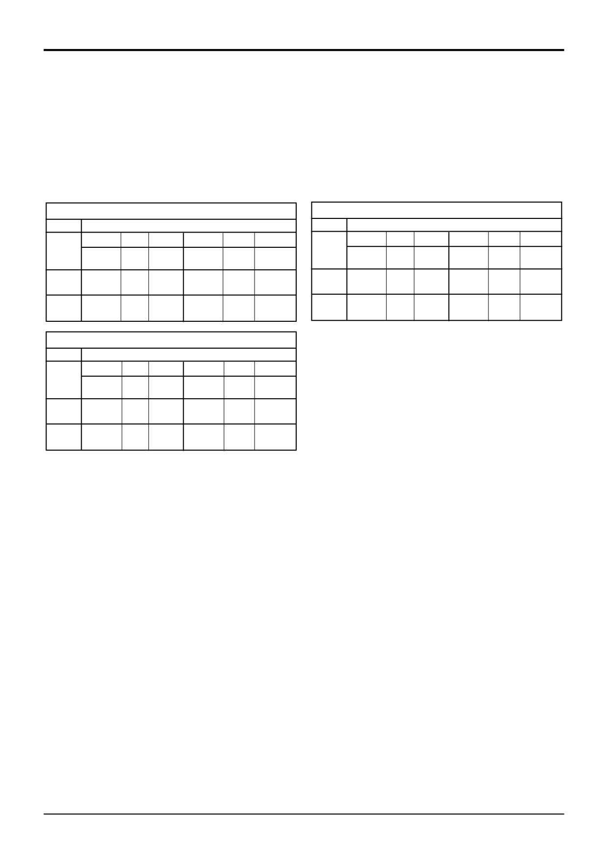
Key to Clutches
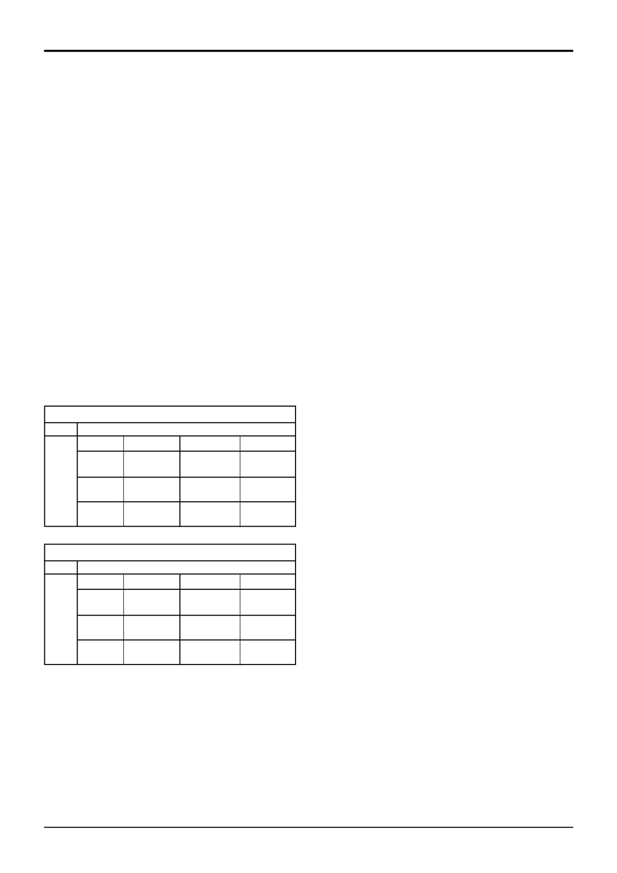
be easy to identify. Draw a table as shown so that you can
T - Forward low ratio clutch pressure
record the results.
U - Forward high ratio clutch pressure
Stall Test Results - 6 Speed Powershift
V - Reverse high ratio clutch pressure
Gear
Clutches engaged
W- Reverse low ratio clutch pressure
Forward
Rev/min
Reverse
Rev/min
X - 6 speed clutch pressure (6 speed gearbox only)
Y - Mainshaft clutch pressure
1st
X,Z
W,Z
Z - Layshaft clutch pressure
2nd
T,Z
V,Z
3rd
U,Z
W,Y
Stall Test Results - 4 Speed Powershift
Gear
Clutches engaged
Forward
Rev/min
Reverse
Rev/min
1st
T,Z
W,Z
2nd
U,Z
V,Z
3rd
T,Y
W,Y
1
Ensure that the engine and transmission are at normal
working temperature (the transmission oil must be
above 50°C). Run engine at maximum speed and check
the No Load Speed (High Idle Speed - U.S.A). See
Engine Technical Data for correct figure; adjust if
necessary.
2
Apply parking brake and footbrake firmly. If necessary,
set the machine against a fixed obstruction.
9803/3280
Issue 1
Section F
Transmission
Section F
65 - 2
Service Procedures
65 - 2
Powershift Gearbox
Torque Converter Stall Test, cont’d
Interpreting the Test Results
If all the engine speeds are below the stated figures either
the engine is losing power and should be
serviced/overhauled or the torque converter reaction
member clutch is slipping. To check the engine, select
Neutral, open throttle fully and operate an excavator service
to 'blow off' the main relief valve. Engine speed should fall to
slightly below the Maximum Governed Speed (see Engine
Technical Data). If engine speed is correct the torque
converter reaction member clutch is slipping.
If all the engine speeds are higher than the stated figures in
all gears the torque converter safety relief valve may be
faulty. Alternatively there may be internal oil leakage.
If engine speeds are higher than the stated figures in some
gears, check the transmission for clutch slippage or internal
leakage. Look at the example below and see how the results
can be used to isolate a suspect clutch.
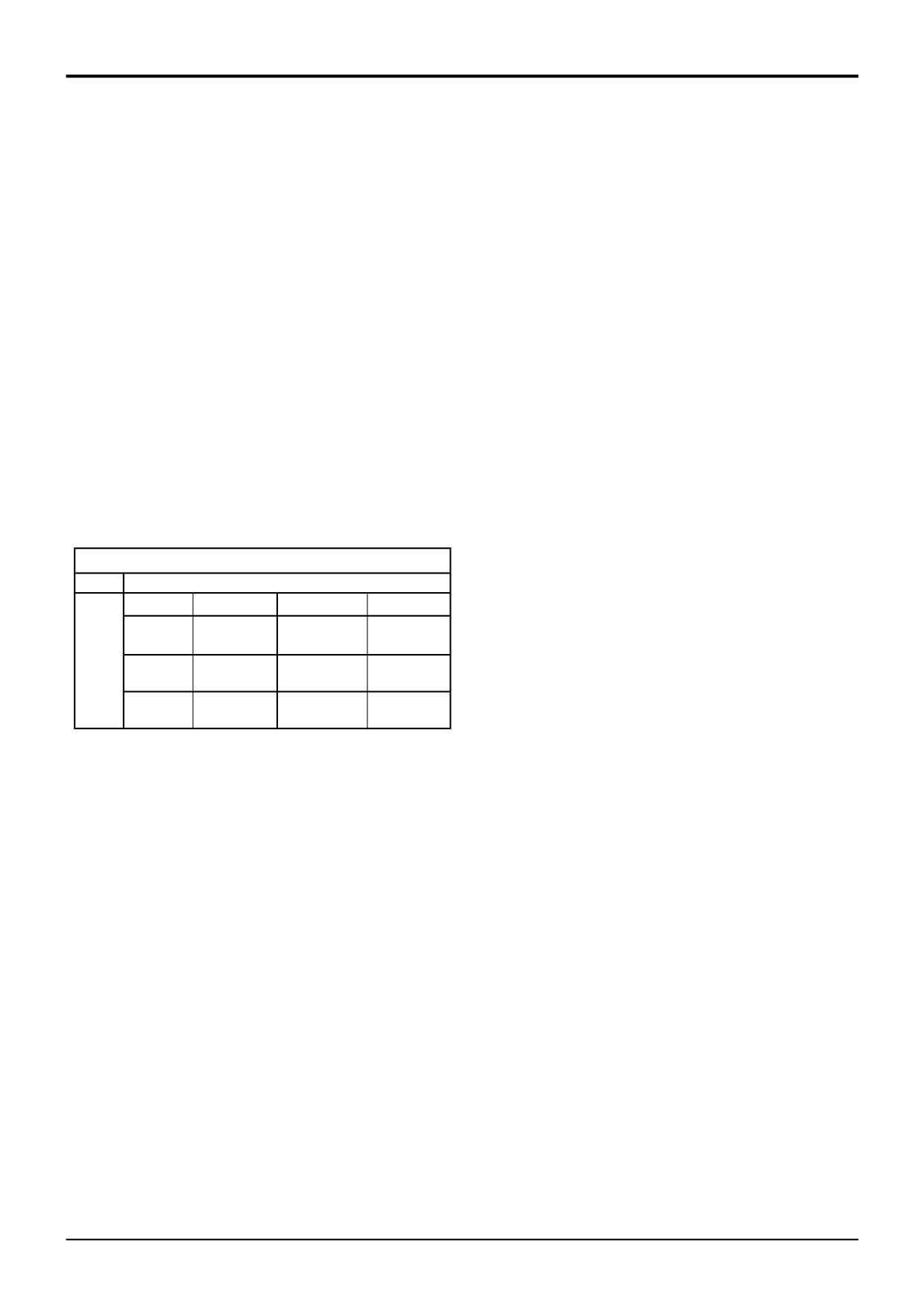
Stall Test Results - 6 Speed Powershift
Gear
Clutches engaged
Forward
Rev/min
Reverse
Rev/min
1st
X,Z
1990
W,Z
1980
2nd
T,Z
2060
V,Z
1975
3rd
U,Z
1985
W,Y
1990
In the example shown, we can see that the engine speed is
abnormally high when 2nd gear forward drive is selected,
indicating a slipping clutch, possibly T or Z. We can now use
the results to determine which clutch is at fault.
From the table we can see that there is no problem with
clutch Z since it is engaged in other gears, the stall speeds
for those gears are normal. This indicates that clutch T is
slipping.
Clutches may be slip for several reasons. Hydraulic leakage
is possible and this can be confirmed by carring out a
pressure test, see Pressure Testing - Individual Clutches.
9803/3280
Issue 1
Section F
Transmission
Section F
66 - 1
Service Procedures
66 - 1
Powershift Gearbox
Pressure and Flow Testing
J
Y
Z
A
T
U
S
L
X
M
F
B
C
W
V
A396470
9803/3280
Issue 1
Section F
Transmission
Section F
66 - 2
Service Procedures
66 - 2
Powershift Gearbox
Pressure and Flow Testing
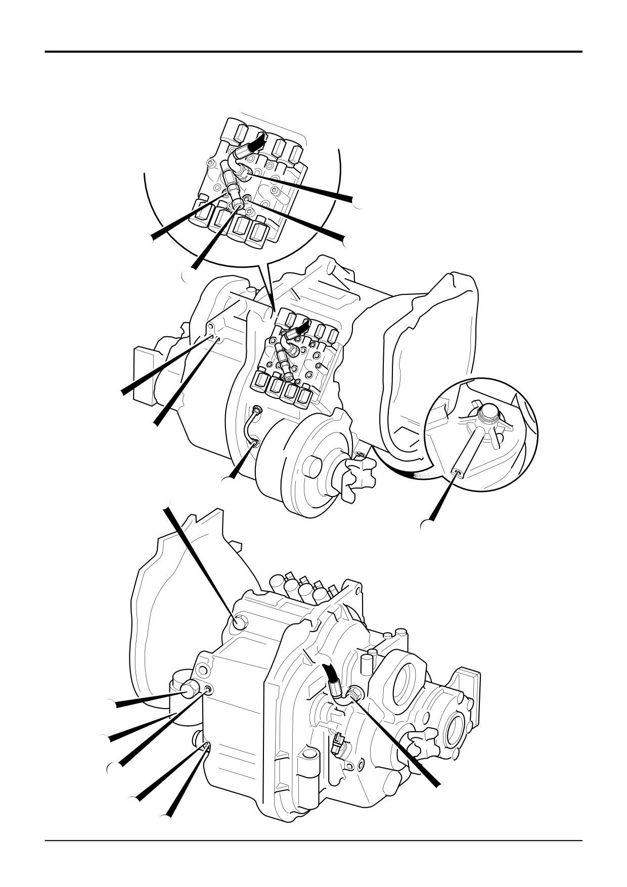
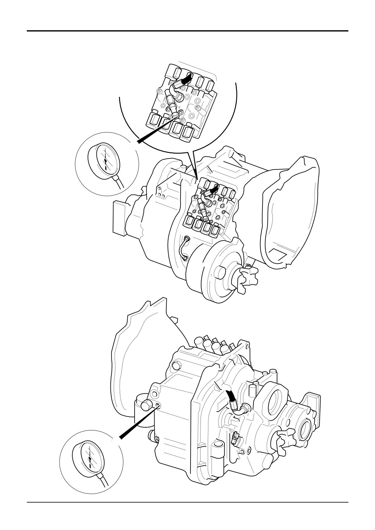
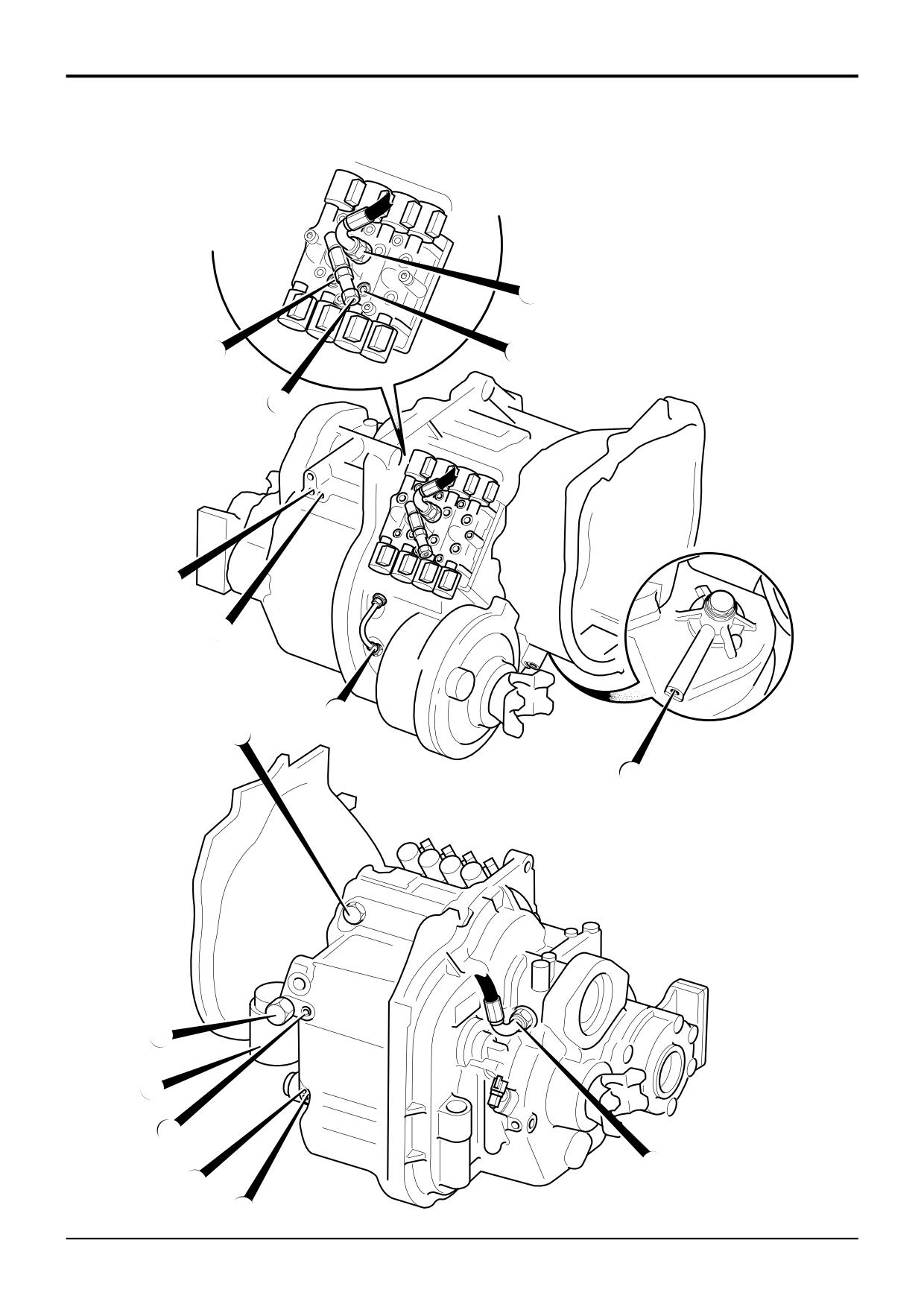
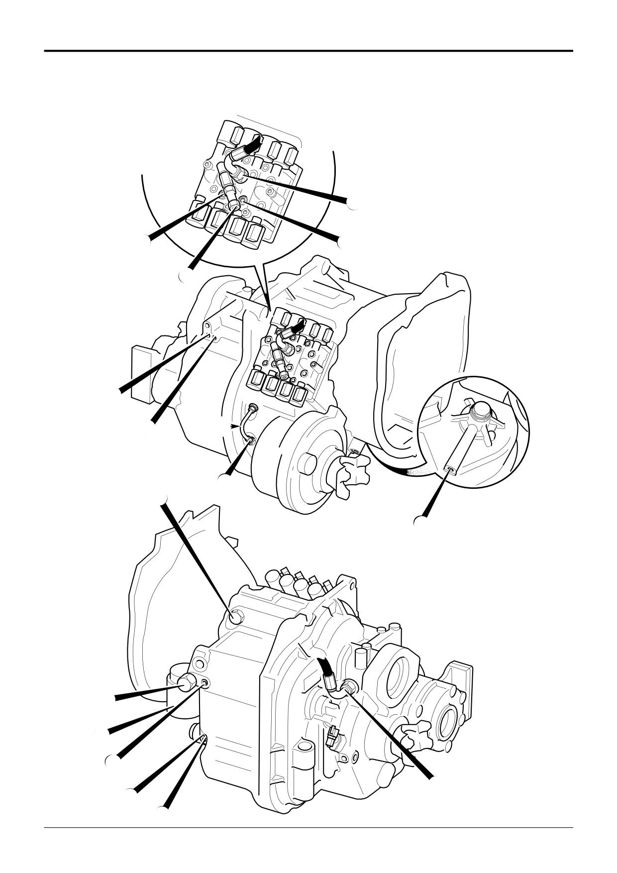
TEST POINTS
Before completing any of the transmission pressure/flow
A - Mainline pressure
tests, make sure that the oil level is correct and at normal
B - Converter inlet/converter relief valve pressure
operating temperature (not less than 50°C).
C - Converter outlet pressure
All gauges etc used in the following pressure/flow tests are
F - Pump flow (remove filter and fit adapters)
shown in Service Tools.
J - Lubrication pressure
! WARNING
Clutches:
Fine jets of hydraulic oil at high pressure can penetrate
S - 2/4 wheel drive clutch pressure
the skin. Do not use your fingers to check for hydraulic
oil leaks. Do not put your face close to suspected leaks.
T - Forward low ratio clutch pressure
Hold a piece of cardboard close to suspected leaks and
U - Forward high ratio clutch pressure
then inspect the cardboard for signs of hydraulic oil. If
V - Reverse high ratio clutch pressure
hydraulic oil penetrates your skin, get medical help
W- Reverse low ratio clutch pressure
immediately.
HYD 1-1
X - 6 speed clutch pressure (6 speed gearbox only)
Y - Mainshaft clutch pressure
! WARNING
Z - Layshaft clutch pressure
Take care when disconnecting hydraulic hoses and
fittings as the oil will be HOT.
Trans 1-2
Other items:
L - Torque converter relief valve
! WARNING
M - Pressure maintenance valve
DO NOT go underneath the machine with the engine
running. Switch off the engine, apply the parking brake
and chock both sides of all wheels before going
underneath the machine.
Test Procedures
Trans 2-1
Pump Flow
! WARNING
Mainline Pressure
If a 4 wheel drive machine is to be raised and the
Converter In Pressure
engine/transmission run, make sure all four wheels are
Converter Relief (Safety) Valve Pressure
off the ground and supported by axle stands. If only one
pair of wheels is raised, the machine could still drive
Converter Out Pressure/Oil Cooler Flow Rate
through the other axle.
Lubrication Pressure
Trans 2-2/2
Clutches:-
! WARNING
Isolating a Suspect Clutch
Under no circumstances must the engine be run with the
Individual Clutch Leakage Test
transmission in gear and only one driving wheel jacked
clear of the ground, since the wheel on the ground will
move the machine.
INT-3-1-16
9803/3280
Issue 1
Section F
Transmission
Section F
66 - 3
Service Procedures
66 - 3
Powershift Gearbox
Pressure and Flow Testing
A
B
A396990
9803/3280
Issue 1
Section F
Transmission
Section F
66 - 4
Service Procedures
66 - 4
Powershift Gearbox
Pressure and Flow Testing, cont’d
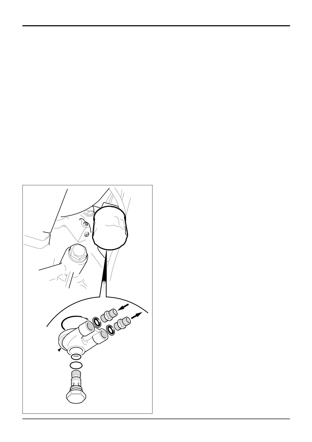
Pump Flow
Mainline Pressure
1
Stop engine, remove the gearbox oil filter and fit
1
Stop engine, connect a 0-20 bar (0-300 lbf/in2) pressure
adapter X
(460/15708) into the gearbox casing.
gauge to test connector A.
Connect flowmeter W (892/00268).
2
Start engine and run at
1000 rev/min. With the
2
Start engine and run at
1000 rev/min. With the
transmission in neutral the pressure gauge will show
transmission in neutral the flowmeter will show the
the Main Line Pressure which should be as shown in
Pump Flow which should be as shown in Technical
Technical Data. A low reading can be caused by either
Data. A low reading indicates a worn pump or blocked
a faulty pressure maintenance valve or a worn pump. A
suction strainer.
high or low reading may indicate a faulty pressure
maintenance valve.
3
Repeat step 2 and note gauge readings with engine
running at 2000 rev/min.
3
Repeat step 2, with engine running at 2000 rev/min
note gauge readings which should be as shown in
4
Stop engine and remove test adapters, refit filter.
Technical Data.
4
Stop engine and remove test gauge.
Converter In Pressure
Note that the converter in pressure is affected by the torque
converter relief valve operation. Before carrying out tests
check the operation of the relief valve (see Converter Relief
(Safety) Valve Pressure).
1
Stop engine, connect a 0-20 bar (0-300 lbf/in2) pressure
gauge to test point B.
2
Start the engine and run at 1000 rev/min. With the
transmission in neutral the pressure gauge will show
Converter In Pressure which should be as shown in
Technical Data. A high or low reading could indicate a
faulty converter relief valve.
3
Remove pressure test gauge.
W
X
A396980
9803/3280
Issue 1
Section F
Transmission
Section F
66 - 5
Service Procedures
66 - 5
Powershift Gearbox
Pressure and Flow Testing
J
C
K
B
P
A397000
9803/3280
Issue 1
Section F
Transmission
Section F
66 - 6
Service Procedures
66 - 6
Powershift Gearbox
Pressure and Flow Testing, cont’d
Converter Relief (Safety) Valve Pressure
The purpose of the torque converter relief valve is to protect
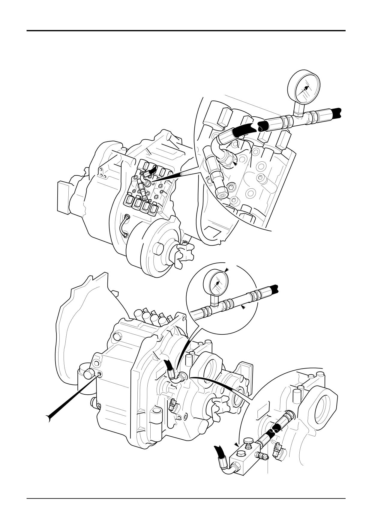
Converter Out Pressure/Oil Cooler Flow Rate
the torque converter from excessive oil pressure. Excessive
oil pressure can be generated when the transmission oil
Note that the converter out pressure and oil cooler flow rate
temperature is below 50°C and/or the engine is run at over
are affected by the torque converter relief valve operation.
2000 rev/min. In this event the relief valve opens and returns
Before carrying out tests check the operation of the relief
oil directly to the transmission sump, bypassing the torque
valve (see Converter Relief (Safety) Valve Pressure.
converter, cooler and clutch lubrication circuits, protecting
against damage due to excessive pressure. For this reason
1
Stop engine, connect a 0-20 bar (0-300 lbf/in2) pressure
it is essential that the transmission oil is above 50°C and
gauge and flowmeter into the converter out line as
the engine is run between idle and 1000 rev/min when
shown at C and K respectively.
testing the relief valve.
2
Run the engine at 1000 rev/min with transmission in
1
Connect a 0-20 bar (0-300 lbf/in2) pressure gauge to
neutral. The pressure gauge indicates the Converter
test point B.
Out Pressure and the flowmeter indicates the Oil
Cooler Flow Rate, both readings should be as
2
Fit a load valve P into the converter out line.
specified in Technical Data. A high pressure together
with low flow could be caused by a blocked oil cooler
or internal leakage.
! CAUTION
Make sure the load valve is in the OPEN position, (the
3
Repeat step 2, with engine running at 2000 rev/min
adjusting knob screwed fully OUT), before starting the
note gauge readings which should be as shown in
following pressure test. Failure to do this could damage
Technical Data.
the pump.
HYD 4-4/1
4
Stop engine, remove test gauges and refit hoses to
original position.
DO NOT allow the pressure to exceed 8.3 bar (120 lbf/in2) or
damage to the converter seals will be caused.
Lubrication Pressure
3
Start the engine and run at 1000 rev/min. With the
Note that the lubrication pressure is affected by the torque
transmission in neutral, slowly screw down the load
converter relief valve operation. Before carrying out tests
valve P whilst observing the gauge reading which
check the operation of the relief valve (see Converter Relief
should rise to the Converter Relief (Safety) Valve
(Safety) Valve Pressure.
setting as specified in Technical Data.
1
Stop engine, connect a suitable pressure gauge into
Note that the gauge pressure will fall once the valve has
the return line from the oil cooler to the transmission as
opened. This is normal relief valve operation and does not
shown at J.
indicate a fault. If necessary reset the load valve P and
perform the test again, watching the pressure gauge
2
Start the engine and run at 1000 rev/min. With the
carefully.
transmission in neutral the pressure gauge will indicate
the Lubrication Pressure which should be as specified
4
If the converter relief valve opens at a pressure higher
in Technical Data.
than specified then the valve is faulty. A low opening
pressure indicates a leaking pump to casing seal or a
3
Repeat step 2 and note gauge readings with engine
faulty converter relief valve.
running at 2000 rev/min. If the pressure is high the oil
cooler may be blocked, (see Converter Out
5
Stop engine, remove test gauges and load valve. Refit
Pressure/Oil Cooler Flow Rate).
hoses to original position.
4
Stop engine and remove pressure gauge.
9803/3280
Issue 1
Section F
Transmission
Section F
66 - 7
Service Procedures
66 - 7
Powershift Gearbox
Pressure and Flow Testing
J
Y
Z
A
T
U
S
L
X
M
F
B
C
W
V
A396470
9803/3280
Issue 1
Section F
Transmission
Section F
66 - 8
Service Procedures
66 - 8
Powershift Gearbox
Pressure Testing - Clutches
Isolating a Suspect Clutch
By performing the tests in the first 3 gears in forward and
3
Start engine and run at 1000 rev/min, engage 1st gear
reverse all the clutches in the gearbox will be engaged,
forward. Record the pressure reading. Repeat the test
ensuring any clutch leakage will be easy to identify. Draw a
for 2nd and 3rd gears forward and 1st, 2nd and 3rd
table as shown so that you can record the results.
gears revers. Record the pressure readings as shown in
the example below:
Clutch Pressure Test Results - 6 Speed Powershift
Clutch Pressure Test Results - 6 Speed Powershift
Gear
Clutches engaged
Gear
Clutches engaged
Forward
bar
lbf/in2
Reverse
bar
lbf/in2
Forward
bar
lbf/in2
Reverse
bar
lbf/in2
1st
X,Z
W,Z
1st
X,Z
13.4
194
W,Z
13.4
194
2nd
T,Z
V,Z
2nd
T,Z
12.0
175
V,Z
13.6
197
3rd
U,Z
W,Y
3rd
U,Z
13.5
195
W,Y
13.5
195
Readings should not vary between clutches by more than
Clutch Pressure Test Results - 4 Speed Powershift
0.7 bar (10 lbf/in2). In the example shown, we can see that
Gear
Clutches engaged
pressure is low when 2nd gear forward is selected,
Forward
bar
lbf/in2
Reverse
bar
lbf/in2
indicating clutch leakage.
1st
T,Z
W,Z
From the table we that the layshaft clutch Z is working
normally (1st and 3rd gear forward and 1st and 2nd gears
2nd
U,Z
V,Z
reverse all show normal operating pressure). We can
assume that the forward low clutch T is leaking.
3rd
T,Y
W,Y
By carring out ‘Individual Clutch Leakage Tests', (see next
page) we can confirm that the forward low clutch T is
1
Stop engine, connect a 0-20 bar (0-300 lbf/in2) pressure
leaking.
gauge to test connector A (mainline pressure test
point).
2
Make sure that both sides of all four wheels are
chocked. Apply the footbrake and parking brake.
Note: When fully engaged, the parking brake electrically
disconnects the transmission drive; this prevents the
machine from being driven with the parkbrake on. Therefore,
so that we can complete the test, move the parkbrake lever
fractionally forward until the warning light is just
extinguished; hold the lever in this position for the duration
of the test. DO NOT move the lever too far forward,
otherwise the parkbrake will not be fully operational.
Alternatively, disconnect the switch at the park brake.
9803/3280
Issue 1
Section F
Transmission
Section F
66 - 9
Service Procedures
66 - 9
Powershift Gearbox
Pressure and Flow Testing
J
Y
Z
A
T
U
R
S
L
X
M
F
B
C
W
V
A396470
9803/3280
Issue 1
Section F
Transmission
Section F
66 - 10
Service Procedures
66 - 10
Powershift Gearbox
Pressure Testing - Clutches
Individual Clutch Leakage Test
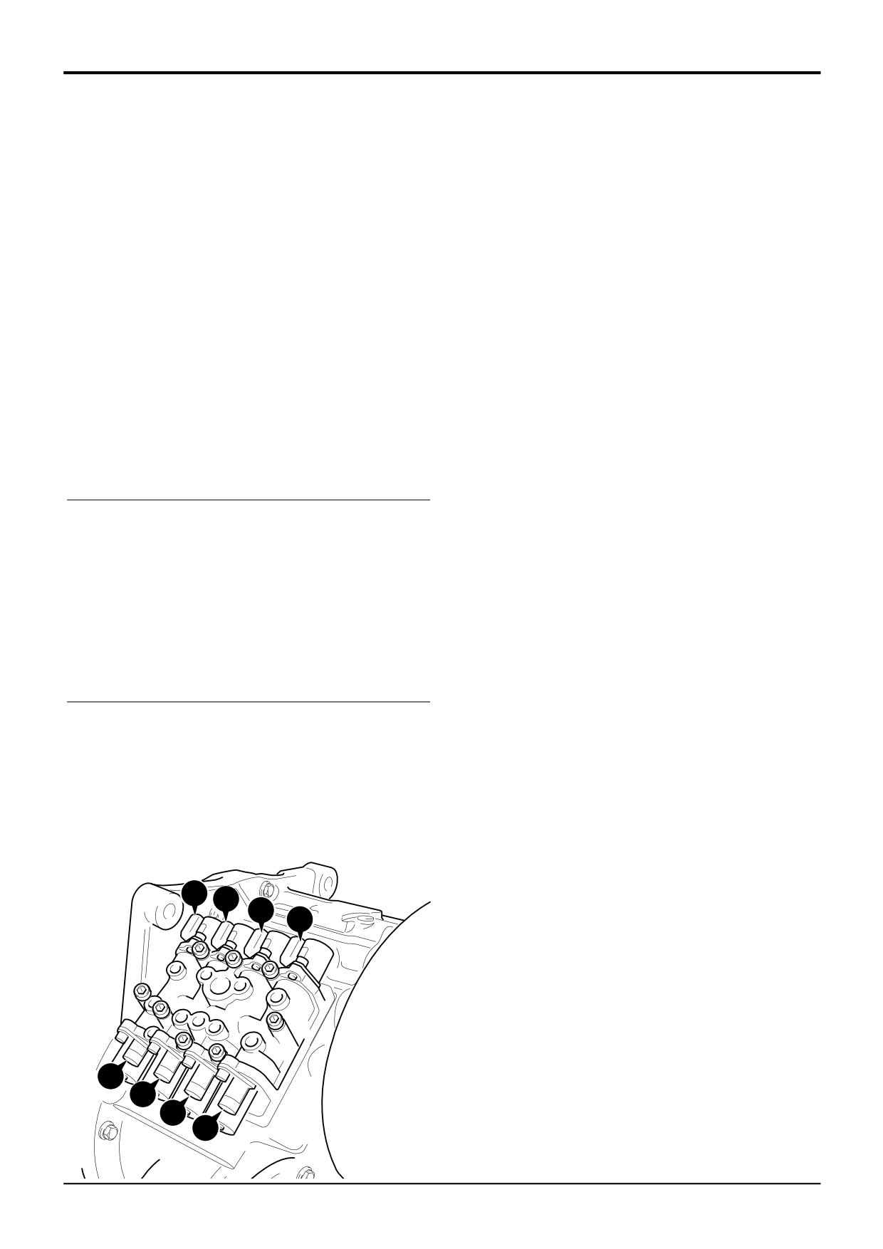
When testing individual clutch pressures it is necessary to
In the following procedures the forward low clutch (T) is
isolate the clutch being tested. So for instance, on a 6 speed
tested, therefore in step 2 a pressure gauge is connected to
gearbox, to check the forward low clutch T we must select
the forward low clutch test point.
2nd gear forward - this would energise the forward low (T)
and layshaft (Z) clutches. Because we only want to check
When testing other suspect clutches connect a gauge to the
the forward low (T) clutch pressure and not the layshaft (Z)
relevant suspect clutch test point. Because the forward low
clutch pressure, remove the electrical connector to the 6
clutch is suspect, a gear must be selected that will use the
speed clutch solenoid Zs BEFORE selecting 2nd gear.
forward low clutch, in this instance 2nd gear forward.
Use the table below to determine which solenoid electrical
Note: When testing the 2/4WD clutch remove the feed pipe
connectors should be removed when pressure testing
R and fit service tool. This pipe incorporates a test point.
individual clutches. Note that as the first 3 forward and
Replace the original pipe when testing is complete.
reverse gears utilise all clutches, there is no need to select
other gears when testing for leakage.
1
Stop engine, connect a 0-20 bar (0-300 lbf/in2) pressure
gauge to test connector A, (mainline pressure test
6 Speed Gearbox
point).
Gear
Clutches Engaged (Solenoids Energised)
Selected
2
Connect a 0-20 bar (0-300 lbf/in2) pressure gauge to
test connector T (forward low ratio clutch test point).
1st Forward
6 Speed & Layshaft - X,Z
(Xs,Zs)
2nd Forward
Forward Low & Layshaft - T,Z
(Ts,Zs)
3
Remove the layshaft clutch solenoid feed connector Zs,
3rd Forward
Forward High & Layshaft - U,Z
(Us,sZ)
at the solenoid control valve. This ensures that only the
forward low clutch T is energised when 2nd gear
1st Reverse
Reverse Low & Layshaft - W,Z
(Ws,Zs)
forward is selected.
2nd Reverse
Reverse High & Layshaft - V,Z
(Vs,Zs)
3rd Reverse
Reverse Low & Mainshaft - W,Y (Ws,Ys)
4
Make sure that both sides of all four wheels are
chocked. Apply the footbrake and parking brake.
4 Speed Gearbox
Note: When fully engaged, the parking brake electrically
Gear
Clutches Engaged (Solenoids Energised)
disconnects the transmission drive; this prevents the
Selected
machine from being driven with the parkbrake on. Therefore,
so that we can complete the test, move the parkbrake lever
1st Forward
Forward Low & Layshaft - T,Z
(Ts,Zs )
fractionally forward until the warning light is just
2nd Forward
Forward High & Layshaft - U,Z
(Us,Zs)
extinguished; hold the lever in this position for the duration
3rd Forward
Forward Low & Mainshaf - T,Y
(Ts,Ys)
of the test. DO NOT move the lever too far forward,
otherwise the parkbrake will not be fully operational.
1st Reverse
Reverse Low & Layshaft - W,Z (Ws,Zs)
Alternatively, disconnect the switch at the park brake.
2nd Reverse
Reverse High & Layshaft - V,Z
(Vs,Zs)
3rd Reverse
Reverse Low & Mainshaft - W,Y (Ws,Ys)
5
Start engine and run at 1000 rev/min, select 2nd gear
forward. Note the pressure readings on both gauges,
which should not vary by more than 0.7 bar (10 lbf/in2).
If the difference on the gauges is greater than 0.7 bar
(10 lbf/in2) do the following:
Ts
Us
Ws
Vs
a Stop the engine and interchange the gauges.
b Start the engine and run at 1000 rev/min, select
2nd gear forward. If the difference on the gauges is
still greater than 0.7 bar (10 lbf/in2) dismantle the
forward low clutch for servicing.
c If after interchanging the gauges, the readings are
different than at step 5, have the gauges calibrated
and repeat the testing procedure.
Ss
Ys
Zs
Xs
9803/3280
Issue 1
Section F
Transmission
Section F
67 - 1
Service Procedures
67 - 1
Powershift Gearbox
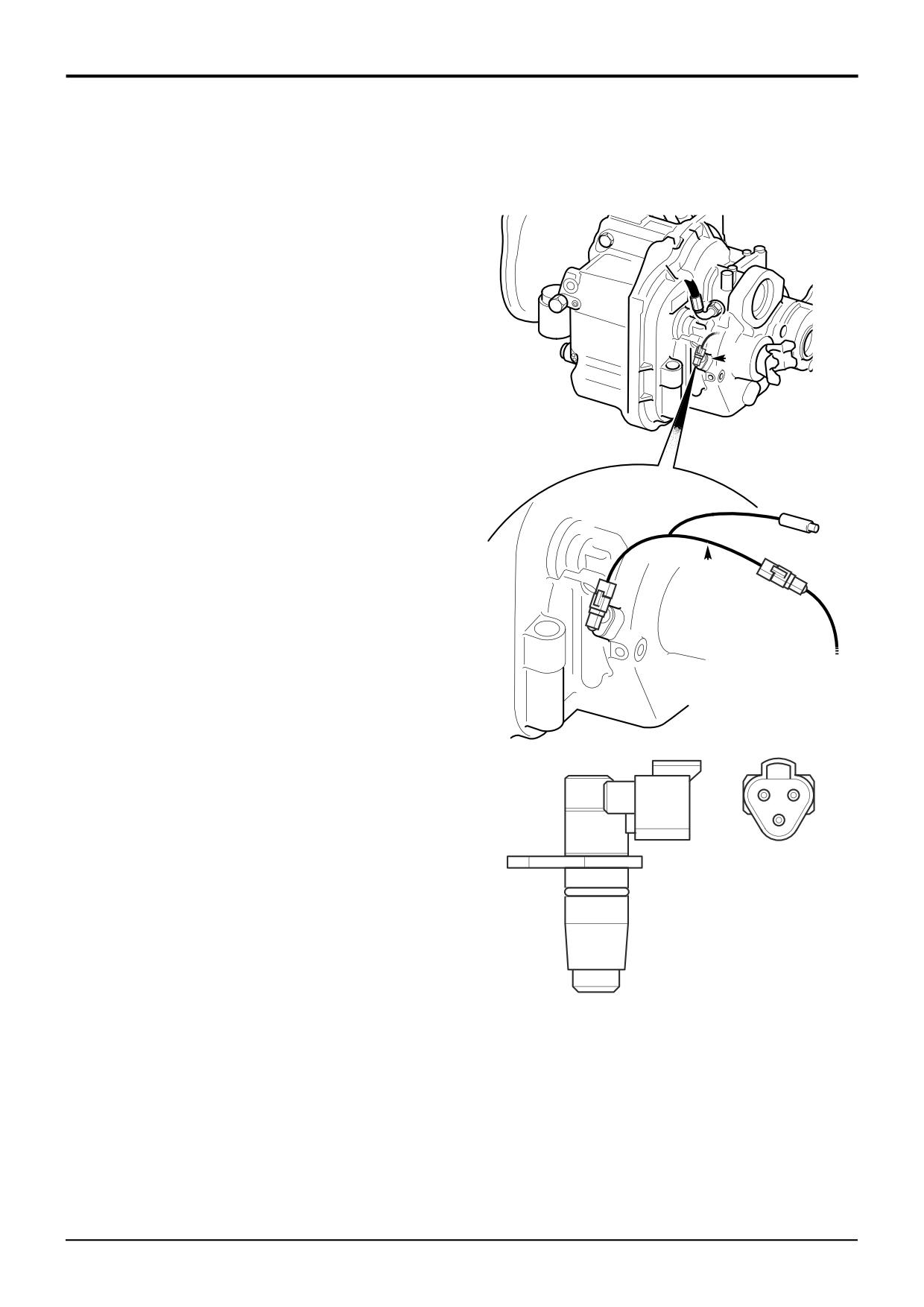
Speed Sensor
Powershift machines fitted with an electronic control unit
(ShiftMaster ECU) or a speedometer have a speed sensor D
fitted. The speed sensor detects the speed of rotation of the
gearbox output shaft and relays this information to the ECU
or speedometer as applicable.
The sensor detects the passing of the gear teeth on the
output gear. When adjacent to the top of a gear tooth the
sensor electrical output turns ON, when adjacent to a gap
between the teeth the sensor output turns OFF. In this way
the frequency of the electrical signal changes according to
D
the speed of gear rotation and therefore machine road
speed.
The ShiftMaster ECU uses the input from the speed sensor
to determine gear shift points. Failure of the speed sensor
or its wiring will enable an ECU ‘Limp Mode’, preventing the
use of 4th, 5th, and 6th gears. See Fault Finding -
Powershift Gearbox.
Testing
The speed sensor can be tested in situ without removing it
by means of service test harness 892/01096 .
E
1
Park the machine on firm level ground, engage the
parking brake and set the transmission to neutral.
Lower the loader arms to the ground. Switch OFF the
engine and remove the starter key.
2
Connect the test harness E as shown. Tie back and
secure the wires clear of the driveshaft and other
moving components, in a position where the light
emitting diode (LED) can be seen while operating the
machine.
3
Turn the engine ON and drive the machine forward
B
A
approximately 2 m (6 ft), make sure it is clear in front.
Alternatively raise the wheels off the ground. If the
C
sensor is operating correctly the LED will illuminate as
the gear teeth pass the sensor, when the speed
Key:
increases the LED will flash at a greater frequency until
becoming continuously illuminated at higher speeds.
A Ground
B +V
4
If the LED fails to illuminate carefully check the relevant
C Output
wires and connectors for damage. Repair as required
and re-test the sensor as described above. It should be
noted that the speed sensor is normally a reliable
component and a fault is more likely attributed to
A405380
damaged wires or electrical connectors, see Electrical
Connections - Powershift Gearbox - 6 Speed.
9803/3280
Issue 1
Section F
Transmission
Section F
68 - 1
Service Procedures
68 - 1
Powershift Gearbox - 6 Speed (ShiftMaster)
Electronic Control Unit
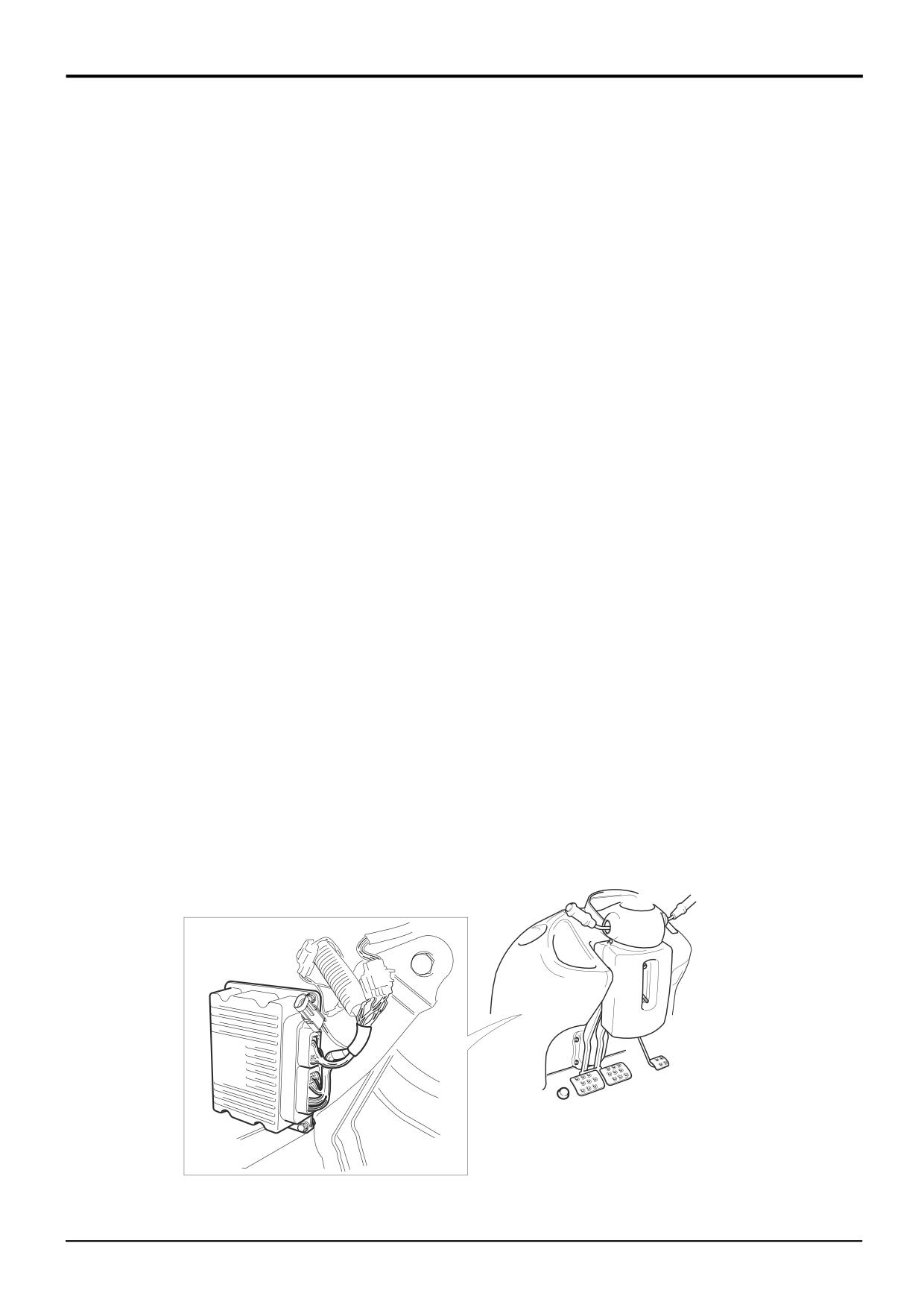
The PS766 6 speed gearbox is controlled by an Electronic
Software Upgrades
Control Unit (ShiftMaster ECU). The ECU is located behind
From time to time a ShiftMaster ECU ‘Application Software’
the front console as shown at A.
upgrades may be made available by JCB Service. If
necessary ‘Application Software’ can be loaded into the
The ECU is housed in a rugged case protected from ingress
ECU flash memory using a laptop PC and the ShiftMaster
of dirt and moisture. Gearbox faults are more likely to be
Flash Programmer application. This application is part of
caused by faulty or damaged wiring, electrical components
the JCB Service Master package found on the JCB Service
or hydraulic faults than by failure of the ShiftMaster ECU.
Technical Information CD’s. The Flash Programmer
application includes comprehensive help files.
Fault Finding
Note that the ECU contains 2 sets of software, ‘Application
When fault finding note the following:
Software’ and ‘Setup Data’. The ‘Setup Data’ is specific to a
machine variant and can not be changed or replaced.
Make sure you understand the normal operation
characteristics of the 6 speed gearbox. Some characteristics
Renewing The ECU
may be interpreted as faults by some operators. See Basic
Before renewing the ECU note the following:
Operation - ShiftMaster Operation Characteristics.
The ShiftMaster ECU is a non serviceable part. Any units
The ShiftMaster ECU incorporates ‘Limp Modes’. These
returned under warranty found to have been tampered with
modes can operate in response to other gearbox faults.
will invalidate any claim.
Make sure you understand the characteristics of the ‘Limp
Modes’, see Fault Finding - Powershift Gearbox.
ECU’s are configured at the factory for each machine variant
and are not interchangeable between machines. Although
The simplest and best way to fault find the 6 speed gearbox
the part numbers may be the same, the internal software
electrical system, (including the ECU) is by using ShiftMaster
may not be. DO NOT interchange ECU’s between
Diagnostics software and a laptop PC. See Diagnostics
machines.
User Guide. This diagnostics system enables the engineer
to quickly identify faults with specific electrical circuits or
Before renewing the ECU carry out all the relevant fault
devices. The devices electrical connections, locations and
finding and diagnostics to confirm ECU failure. Units
wire identifications are given in Electrical Connections -
returned under warranty found not to be faulty will invalidate
Powershift Gearbox - 6 Speed. See also Section C -
any claim.
Harness Data.
If the facilities to use the ShiftMaster Diagnostics software
system are not available, the gearbox and ECU can still be
checked using a conventional multimeter, see Electrical
Connections - Powershift Gearbox - 6 Speed. See also
Section C - Harness Data.
A
A405370
9803/3280
Issue 1
Section F
Transmission
Section F
69 - 1
Service Procedures
69 - 1
Powershift Gearbox - 6 speed
ShiftMaster Diagnostics - User Guide
1. Introduction
2. Care & Safety
ShiftMaster Diagnostics software is a PC based
Diagnostics Tool designed to be an easy to use fault finding
! WARNING
tool for the Service Engineer using a laptop PC. ShiftMaster
Be sure to read and follow any on-screen instructions
Diagnostics employs the graphical strengths of the
issued by ShiftMaster Diagnostics. Failure to follow
Microsoft Windows operating environment to simplify
correct procedure could result in death or injury.
electrical fault finding within the ShiftMaster ECU control
system used on Powershift PS766 6 speed gearboxes.
ShiftMaster Diagnostics is only intended for use with the
ShiftMaster ECU and does not support older versions of
Powershift Controllers used on the PS750 series gearboxes.
To utilise any supporting ShiftMaster Service Tools requires
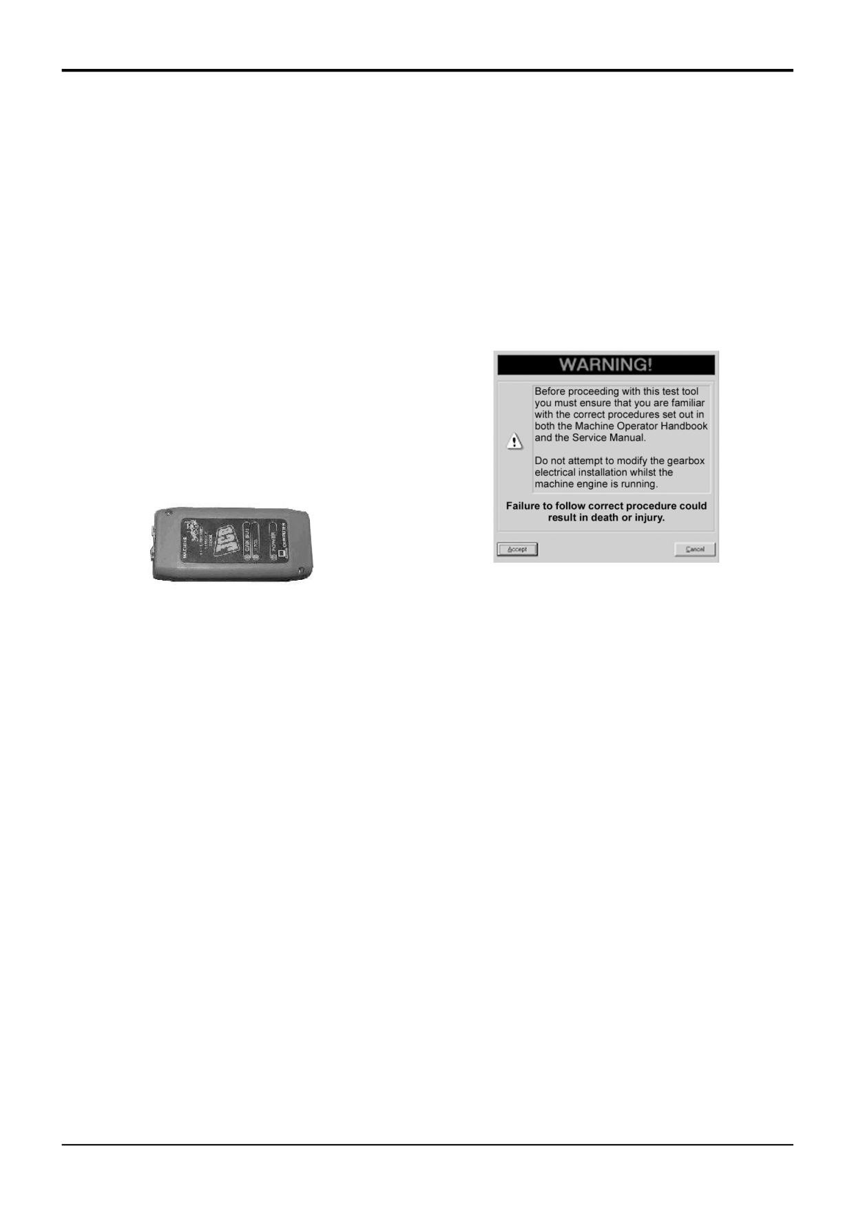
the use of the JCB Data Link Adaptor [or DLA] (717/ 20138)
which is part of the standard JCB Electronic Service Tool
Kit, part number 892/01033.
S404180
S404170
This software is intended for use on IBM Compatible
Personal Computers (PCs) running Windows 9x or
3. Installing ShiftMaster Diagnostics
Windows2000 operating systems but is not compatible with
The ShiftMaster Diagnostics tool is fully integrated within
either earlier versions of Windows 3.x.
JCB ServiceMaster.
All distributed software can be found on Disk 3 (CD3 -
For full instructions on how to install the ShiftMaster
Adobe) of the JCB Technical Information Parts and Service
Diagnostics software please refer to the documentation
CD-ROM set from Issue 19 onwards. This disk is also
which accompanies JCB Service Master.
supplied as part of the Electronic Service Tool Kit. Copies of
this CD-ROM can be purchased from JCB Service.
If you have successfully installed ShiftMaster Diagnostics
Alternatively, in due course software will become available
but are experiencing difficulties with getting your PC to
for download over the internet via JCBs' Techweb service.
communicate with an ECU then there is a Troubleshooting
Please refer to the available software for full installation
Guide built into the ShiftMaster Diagnostics Help menu.
instructions.
9803/3280
Issue 1
Section F
Transmission
Section F
69 - 2
Service Procedures
69 - 2
Powershift Gearbox - 6 speed
ShiftMaster Diagnostics - User Guide
4. Starting ShiftMaster Diagnostics
This document assumes that JCB Service Master has
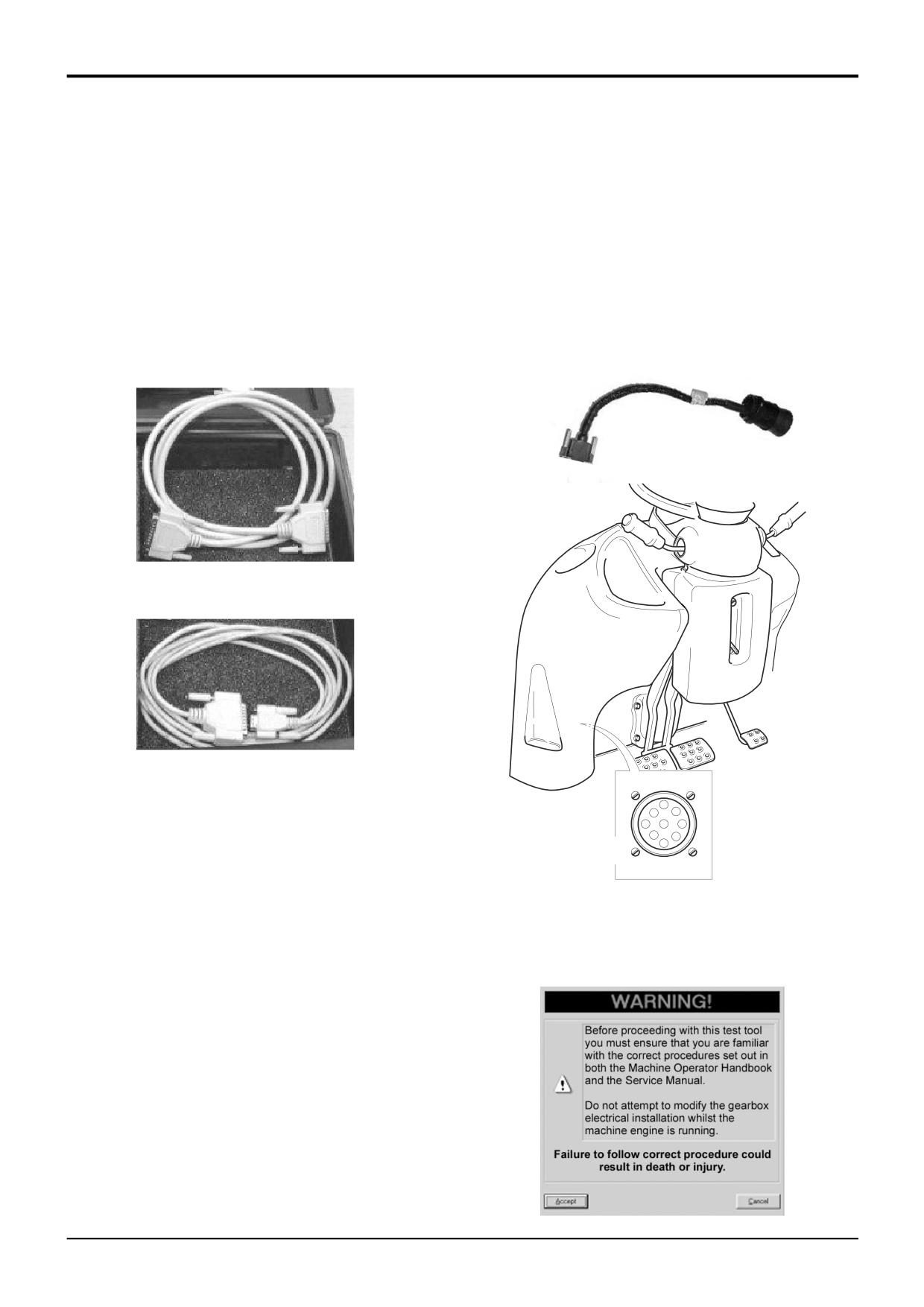
Step 2: Connect the 'Machine Cable' between the DLA and
already been installed.
the machines' Diagnostic Connector. The 'Machine Cable'
has a 15-way D-type connector on one end and a 9-way
Step 1: Connect either the 'Serial PC Cable' (717/20138) or
CAN connector on the other. Plug the 15-way connector into
the 'Parallel PC Cable' (721/11071) between the DLA and a
the DLA and tighten the thumb-screws, then connect the 9-
free port your laptop computer.
way CAN connector into the machines' Diagnostics
The 'Parallel PC Cable' has a 25-way D-type connector on
Connector A and twist the lock-ring to secure it.
both ends or the lead.
S404200
S404190
The 'Serial PC cable' has a 9-way D-type connector on one
end and a 25-Way D-type connector on the other.
S404190
Plug the 25-way male connector into the DLA and the other
connector into a free port on your laptop PC, remembering
to tighten any thumb-screws appropriately.
D
C
E
B
A
F
J
G
H
A
A405350
Step 3: Turn ON the machine ignition and additionally start
the engine if required (taking normal precautions).
Note: Be sure to follow all the cautionary notes given earlier
and those which accompany the software.
S404180
9803/3280
Issue 1
Section F
Transmission
Section F
69 - 3
Service Procedures
69 - 3
Powershift Gearbox - 6 speed
ShiftMaster Diagnostics - User Guide
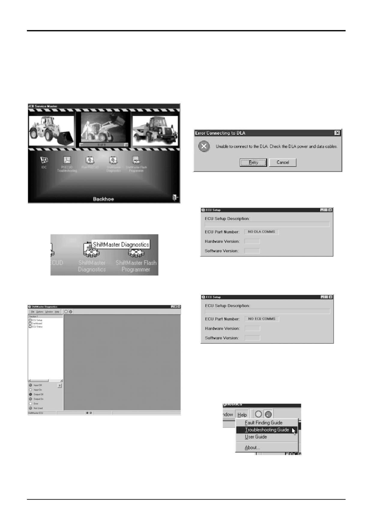
Step 4: Start JCB Service Master. And go to the BHL
Connection Problems:
section.
ShiftMaster Diagnostics will start and can be partly used
even if there are connection problems.
In general, whenever there are problems communicating
with the DLA there will be an error message displayed.
S404140
More specifically, if communications can not be established
with the DLA then the ECU Setup Page will display 'NO DLA
COMMS' where the ECU Part Number should be.
S404210
Step 5: Start the diagnostics tool running by clicking on the
ShiftMaster Diagnostics icon.
S404150
S404220
If communications can not be established with the ECU then
the ECU Setup Page will display 'NO ECU COMMS' where
Step 6: The ShiftMaster Diagnostics tool will then open up
the ECU Part Number should be.
displaying the main window as shown here.
S404160
Note: The ECU must be powered for communications to
work, i.e. the machine ignition must be ON (but the engine
need not be running).
For further details on possible communication problems
please consult the Troubleshooting Guide included in the
Help menu.
S404230
Step
7: To start the ShiftMaster Diagnostics tool
communicating with the ShiftMaster ECU either
click on the Start button or select Start Diagnostics from
the Options Menu. (See later sections for full details.)
S404240
9803/3280
Issue 1